


Languages
Pages
Legal


Clemson UniversityTigerPrints
All Dissertations Dissertations
12-2010
POLY (ACRYLONITRILE-CO-1-VINYLIMIDAZOLE): A NEW MELTPROCESSABLE CARBON FIBERPRECURSORWenjin DengClemson University, [email protected]
Follow this and additional works at: https://tigerprints.clemson.edu/all_dissertations
Part of the Chemistry Commons
This Dissertation is brought to you for free and open access by the Dissertations at TigerPrints. It has been accepted for inclusion in All Dissertations byan authorized administrator of TigerPrints. For more information, please contact [email protected].
Recommended CitationDeng, Wenjin, "POLY (ACRYLONITRILE-CO-1-VINYLIMIDAZOLE): A NEW MELT PROCESSABLE CARBON FIBERPRECURSOR" (2010). All Dissertations. 651.https://tigerprints.clemson.edu/all_dissertations/651

i
POLY (ACRYLONITRILE-CO-1-VINYLIMIDAZOLE): A NEW MELT
PROCESSABLE CARBON FIBER PRECURSOR
A Dissertation
Presented to
the Graduate School of
Clemson University
In Partial Fulfillment
of the Requirements for the Degree
Doctor of Philosophy
Chemistry
by
Wenjin Deng
December 2010
Accepted by:
Dr. Dennis W. Smith, Jr., Advisor
Dr. Rhett C. Smith
Dr. William T. Pennington
Dr. Stephen. E. Creager
Dr. Wesley P. Hoffman

ii
ABSTRACT
Carbon fiber polymer composites have attracted worldwide interest in sporting
goods and aerospace industries due to their excellent specific strength, stiffness and
lightweight. The replacement of solution-spinning process by melt-spinning process is
one of the major approaches to make cost effective carbon fiber. In recent years,
researchers have explored the possibilities to synthesize melt processable carbon fiber
precursors, but their thermal stabilization is still a challenge. The goal for this research
project is to prepare melt processable carbon fiber precursors which have the capability
of thermal stabilization. Acrylonitrile/1-vinylimidazole (AN/VIM) copolymers
containing various mol% of VIM were synthesized by free radical solution
polymerization. The copolymers were characterized by Attenuated Total Reflectance-
Fourier Transform Infrared (ATR-FTIR) spectroscopy, 1H-NMR spectroscopy, gel
permeation chromatography (GPC) and differential scanning calorimetry (DSC). 82/18
mol percent of AN/VIM copolymer based carbon fiber precursor was processed by melt
spinning at 192 °C and thermal stabilization of the melt-spun fiber was achieved by
heating in air at 250 °C for 5 hrs. The change of fiber structure during stabilization
process was confirmed with ATR-IR spectra. Tan Delta value of the stabilized fiber is
0.17, which is much lower than that of as-spun fiber, about 2.12. The oxidized fiber (250
°C / 5 h) did keep its shape after carbonization at 1000 °C for 2 h, which indicates that
poly (acrylonitrile-co-1-vinylimidazole) melt-spun fiber after thermal stabilization can be
carbonized. A novel dispersion polymerization of poly (acrylonitrile – co -1-

iii
vinylimidazole) by using small amount of protonated copolymer itself as a stabilizer was
also introduced in this study.
Poly (acrylonitrile – co -1-vinylimidazolium tetrafluoroborate) and poly
(acrylonitrile – co -1-vinylimidazolium hexafluorophosphate) were synthesized for gas
separation membranes. Terpolymers of methyl methacrylate, methyl acrylate and
furfuryl methacrylate (MMA/MA/FMA) were synthesized successfully by solution
polymerization and emulsion polymerization and were characterized by 1H NMR, ATR-
IR and DSC. The thermo-reversible property of MMA/MA/FMA and BMI cross-linked
polymer was confirmed by solubility test. The MMA/MA/FMA and BMI cross-linked
polymer emulsion can be applied for making thermally re-moldable carbon fiber
composite.

iv
DEDICATION
I dedicate this work to my parents. I am blessed for being their daughter.

v
ACKNOWLEDGMENTS
I want to deeply thank Prof. Dennis W. Smith, Jr. for his tremendous support
throughout my graduate study. I would like to express gratitude to Prof. Rhett C. Smith
for his guidance and help.
I would like to thank my committee members, Prof. Stephen. E. Creager, Prof.
William T. Pennington and Dr. Wesley P. Hoffman for their support.
I would like to thank all my group members. Their help is important for me to
complete PhD work at Clemson. I would also like to thank Dr. Alexander Lobovsky,
Jason Conrad and Erick Vasquez in Dr. Graham Harrison’s group, Tianyu Wu in Dr.
Timothy Long’s group, Dr. Jinyong “Jack” Jin, Adam T. Haldeman and Dr. Chris
Topping in Tetramer Technologies, L.L.C., Joel Barden in Dr. Philip J. Brown’s group
and Dr. Don VanDerveer for their help in my research.

vi
TABLE OF CONTENTS
Page
TITLE PAGE .................................................................................................................... i
ABSTRACT ..................................................................................................................... ii
DEDICATION ................................................................................................................ iv
ACKNOWLEDGMENTS ............................................................................................... v
LIST OF TABLES ........................................................................................................... x
LIST OF FIGURES ........................................................................................................ xi
LIST OF SCHEMES.................................................................................................... xvii
CHAPTER
I. SYNTHESIS AND CHARACTERIZATION OF POLY
(ACRYLONITRILE-CO-1-VINYLIMIDAZOLE)
CARBON FIBER PRECURSOR .......................................................... 1
Introduction .............................................................................................. 1
Synthesis and characterization of AN/VIM
copolymers ......................................................................................... 6
Char yield of precursor polymers .......................................................... 14
Gel fraction of AN/VIM copolymers .................................................... 15
Conclusions ............................................................................................ 17
Experimental .......................................................................................... 17
II. MELT PROCESSING OF POLY (ACRYLONITRILE
-CO-1- VINYLIMIDAZOLE) CARBON FIBER
PRECURSOR .................................................................................... 20
Introduction ............................................................................................ 20
Dynamic oscillatory shear properties of AN/VIM
copolymers ....................................................................................... 21
Dynamic oscillatory shear properties of terpolymers ........................... 30
Characterization of AN/VIM melt-spun fiber ....................................... 34
Conclusions ........................................................................................... 38

vii
Table of Contents (Continued)
Page
Experimental …………………………………………………………..39
III. THERMAL STABILIZATION OF POLY
(ACRYLONITRILE -CO-1- VINYLIMIDAZOLE)
MELT-SPUN FIBER ........................................................................... 42
Introduction ............................................................................................ 42
Effect of O2 on stabilization of AN/VIM melt-spun
fiber .................................................................................................. 46
Conditions of oxidative stabilization ..................................................... 47
ATR-IR spectra of oxidized melt-spun fiber ......................................... 48
Morphology of oxidized melt-spun fibers ............................................. 51
Thermal and dynamic mechanical analysis of 82/18
AN/VIM oxidized fiber.................................................................... 53
Preliminary carbonization experiments ................................................. 56
Conclusions ............................................................................................ 57
Experimental ......................................................................................... 58
IV. DISPERSION POLYMERIZATION OF POLY
(ACRYLONITRILE-CO-1-VINYLIMIDAZOLE) ............................ 61
Introduction ............................................................................................ 62
Effect of VIM content in stabilizer on properties of
the ultimate copolymer particle prepared by
dispersion polymerization ............................................................... 63
Effect of stabilizer concentration on properties of the
ultimate copolymer particle prepared by dispersion
polymerization ................................................................................. 67
Effect of monomer concentration on properties of the
ultimate copolymer particle prepared by
dispersion polymerization ................................................................ 69
Characterization of poly (acrylonitrile-co-1-
vinylimidazole)synthesized by dispersion
polymerization ................................................................................. 71
Conclusions ............................................................................................ 74
Experimental .......................................................................................... 75

viii
Table of Contents (Continued)
Page
V. POLY (ACRYLONITRILE-CO-1-
VINYLIMIDAZOLIUM TETRAFLUROBORATE)
AND POLY (ACRYLONITRILE-
-CO-1-VINYLIMIDAZOLIUM HEXAFLURO-
PHOSPHATE) FOR GAS SEPARATION
MEMBRANES .................................................................................... 78
Introduction ............................................................................................ 78
Synthesis and characterization ............................................................... 82
Gas separation performances of poly (acrylonitrile-
co-1-vinylimidazolium tetrafluroborate) and poly
(acrylonitrile -co-1- vinylimidazolium
hexaflurophosphate) membranes ..................................................... 87
Conclusions ............................................................................................ 89
Experimental ......................................................................................... 89
VI. UV-CURABLE OPTICAL FIBER COATINGS ......................................... 94
Introduction ............................................................................................ 94
Thermal stability .................................................................................... 96
Flexibility ............................................................................................. 100
Conclusions .......................................................................................... 100
Experimental ........................................................................................ 100
VII. THERMO-REVERSIBLE METHYL
METHACRYLATE- METHYL ACRYLATE-
FURFURYL METHACRYLATE
(MMA/MA/FMA) AND BISMALEIMIDE (BMI)
CROSS -LINKED POLYMER ........................................................... 102
Introduction .......................................................................................... 102
Characterization of MA/MMA/FMA terpolymer ................................ 104
Characterization of MA/MMA/FMA and BMI
cross-linked polymer ...................................................................... 110

ix
Table of Contents (Continued)
Page
Thermo-reversible property of MA/MMA/FMA
and BMI cross-linked polymer ................................................. ..112
Remolding experiments ....................................................................... 115
Conclusions .......................................................................................... 117
Experimental ........................................................................................ 117
REFERENCES ............................................................................................................ 121
APPENDICES ............................................................................................................. 133
A: Selected NMR Spectra ............................................................................... 134
B: Selected DLS Spectra ................................................................................ 136
C: Selected DSC Spectra ................................................................................ 146

x
LIST OF TABLES
Table Page
1.1 Tensile strength and density comparisons of
carbon fiber and steel …………………………………………………...2
1.2 Feed and copolymer compositions of AN/VIM
copolymers by starve-fed addition….………………………………….8
1.3 Char Yield of Various AN/VIM Copolymers ................................. ……….15
1.4 Char yield of terpolymers ............................................................................ 15
3.1 Conditions of oxidative stabilization ........................................................... 48
4.1 Effect of VIM content in stabilizer on the ultimate
particles prepared by dispersion polymerization .………..……….…...66
4.2 Effect of stabilizer concentration on the ultimate
particles prepared by dispersion polymerization …….………………..67
4.3 Effect of monomers concentration on the ultimate
particles prepared by dispersion polymerization ………………..…….70
5.1 Gas separation performances of Permeabilities of poly
(acrylonitrile – co -1-vinylimidazolium
tetrafluoroborate) and poly (acrylonitrile –
co -1-vinylimidazolium hexafluorophosphate)
membranes ……………………………………………………………..89
6.1 Flexibility of UV coatings of DeSolite #3471-3-14 with
different percentage of dipentaerythritol penta-/
hexa-acrylate ………………………………………………………..…100
7.1 Glass transiton temperature of MA/MMA/FMA
terpolymer ……………………………………………………………..109

xi
LIST OF FIGURES
Figure Page
1.1 Photograph of a carbon filament (6 μm diameter)
compared to a human hair……………………………………….……….1
1.2 Manufacture process from monomer to carbon fiber ……………………….3
1.2 Structure of photocrosslinkable terpolymer reported by
McGrath’s group …………………………………………………….......5
1.4 Photograph of 82/18 AN/VIM copolymer …………………………………..6
1.5 1H NMR of 82/18 AN/VIM copolymer ……………………………………..9
1.6 ATR-FTIR spectrum of 82/18 AN/VIM copolymer………………………..10
1.7 Gel permeation chromatogram of 82/18 AN/VIM
copolymer in DMF……………………………………………………..11
1.8 Particle size of 82/18 AN/VIM copolymer in DMF
solution by DLS………………………………………………………..12
1.9 DSC thermograms of (a) AN homopolymer; (b) 87/13
AN/VIM; (c) 84/16 AN/VIM; and (d) 81/19
AN/VIM copolymers …………………………………………………..13
1.10 TGA curve of 82/18 AN/VIM copolymer in N2……………………………14
1.11 Photographs of copolymers before and after oxidation
during gel fraction experiment (Oxidized copolymer
retained its shape in DMF even after 7 days) ….………….…………...17
2.1 Dynamic strain sweep of 82/18 AN/VIM copolymer
(200 °C, 10 rad/sec) ……………………………………………………22
2.2 Dynamic temperature sweep of 86/14 AN/VIM
copolymer (0.1 rad/s, 0.1% strain) ……………………………..………23
2.3 Dynamic temperature sweep of 74/26 AN/VIM
copolymer (0.1 rad/s,0.1% strain)………………………………………25

xii
List of Figures (Continued)
Figure Page
2.4 Dynamic temperature sweep of 63/37 AN/VIM
copolymer (0.1 rad/s, 0.1% strain)……………………………………26
2.5 Dynamic temperature sweep of 55/45 AN/VIM
copolymer (0.1 rad/s, 0.1% strain) ...…………………………...........27
2.6 Dynamic frequency sweep of 74/26 AN/VIM
copolymer (180 °C, 0.1% strain) ...………………….…….…………29
2.7 Dynamic time sweep viscosity of 82/18 AN/VIM
copolymer CF33 at 0.1% strain, 1 rad/s, at 205 °C
and 210 °C……………………………………………….………...…30
2.8 Dynamic temperature sweep of 82/12/6 AN/VIM/IP
terpolymer (0.1 rad/s, 0.1% strain) ……………………….………….31
2.9 Dynamic temperature sweep of 82/12/6 AN/VIM/St
terpolymer (0.1 rad/s, 0.1% strain)……………………………………32
2.10 Dynamic time sweep of 82/12/6 AN/VIM/St terpolymer
(210 °C, 1 rad/s, 0.1% strain)………………………………………...33
2.11 Photograph of melt spun fiber of 82/18 AN/VIM ………………………….35
2.12 X-ray diffraction spectrum of melt-spun fiber of 82/18
AN/VIM ……………………………………………………………..36
2.13 ATR-FTIR spectrum of (a) 82/18 AN/VIM copolymer
before melt processing, (b) melt spun fiber of
82/18 AN/VIM………………………………………………………..37
2.14 DSC thermograms of (a) 82/18 AN/VIM copolymer
before melt processing; (b) melt spun fiber of
82/18 AN/VIM………………………………………………………..38
3.1 Intra-molecular nitrile reaction with the formation of
C=N containing ladder structure ……….………………....…………43
3.2 The dehydrogenation eliminations during stabilization
process ……………………………………………………………….43

xiii
List of Figures (Continued)
Figure Page
3.3 Oxidation of ladder polymer a) Ladder polymer
b) Oxidation to hydro peroxide c) Keto-formation
by loss of water d) Tautomeric change to
hydroxy-pyridine sturcture e) Tautomeric change
to pyridone structure …………………………………………………44
3.4 Cross-linking of ladder polymer by loss of H2 …………………………………………....45
3.5 Cross-linking of layers by loss of N2 ………………………………………45
3.6 Photos of melt-spun fiber of 82/18 AN/VIM copolymer:
as-spun fiber color is yellow (left); oxidized fiber
color is black (right) ………….............................................................48
3.7 ATR-IR spectra of 82/18 AN/VIM fibers: (a) as spun
fiber; b) oxidized fiber (210 °C / 80 min); c)
oxidized fiber (220 °C / 2 h); d) oxidized
fiber (250 °C / 5h) ……………………………………………………50
3.8 SEM micrographs of oxidized AN/VIM melt-spun
fiber: a) as-spun fiber; b) oxidized fiber
(210 °C / 80 min); c) oxidized fiber (220 °C / 2 h);
d) oxidized fiber (250 °C / 5h) ………………………………………52
3.9 Thermograms of as-spun & oxidized fibers of 82/18
AN/VIM copolymer by TGA ……………………………………......53
3.10 Tensile storage moduli of as-spun & oxidized fibers of
82/18 AN/VIM copolymer by DMA ………………………………..54
3.11 Tensile loss moduli of as-spun & oxidized fibers of
82/18 AN/VIM copolymer by DMA………………………................55
3.12 Tan delta values of as-spun & oxidized fibers of
82/18 AN/VIM copolymer by DMA….………………..…………….56
3.13 Photograph (left) and SEM image (right) of carbonized
82/18 AN/VIM melt-spun fiber ………………………………...........57

xiv
List of Figures (Continued)
Figure Page
4.1 Mechanism of particle nucleation in the dispersion
polymerization ………………………………………………………..62
4.2 DLS curve of the ultimate AN/VIM copolymer
particles (P(AN-co-VIM) (74:26) as stabilizer,
6.8% stabilizer/monomer (w/w), 7%
monomer/water (w/w), 60 °C for 16h) …………………………….....69
4.3 1H NMR spectrum of AN/VIM copolymer synthesized
by dispersion polymerization …………………………………..……72
4.4 ATR-FTIR spectrum of AN/VIM copolymer synthesized
by dispersion polymerization ………………………..………………73
4.5 Gel permeation chromatogram of AN/VIM copolymer
synthesized by dispersion polymerization ….……………….……….74
5.1 The structure of a typical anisotropic gas separation
membrane …………………………………………………………….78
5.2 Robeson plot of Oxygen/nitrogen selectivity as a
function of oxygen permeability for polymer
membranes …………………………………………………………...80
5.3 Structure of cobalt carrier membrane polymer ………………………….…81
5.4 ATR-IR spectrum of poly (acrylonitrile – co -1-
vinylimidazolium tetrafluoroborate) ...…………………..……………84
5.5 ATR-IR spectrum of poly (acrylonitrile – co -1-
vinylimidazolium hexafluorophosphate) ..…………………….……..85
5.6 19
F NMR of poly (acrylonitrile – co -1-vinylimidazolium
tetrafluoroborate) …………………………………………………….86
5.7 19
F NMR of poly (acrylonitrile – co -1-vinylimidazolium
hexafluorophosphate) ………………………………………………...87

xv
List of Figures (Continued)
Figure Page
5.8 Poly (acrylonitrile – co -1-vinylimidazolium
tetrafluroborate) membrane used for gas
separation (left); poly (acrylonitrile – co -1-
vinylimidazolium hexafluorophosphate) membrane
used for gas separation (right) . Both were made
by Adam T. Haldeman in Tetramer Technologies,
L.L.C) ………………………………………………………………..88
5.9 A photo of the gas permeance testing panel showing the
test cell in the center of the panel and the bubble-
flow meter to the right of the pan ………………………………........92
6.1 The drawing, coating and UV curing processes of the
optical fiber……………………………………………………….…..95
6.2 Structure of dipentaerythritol penta-acrylate ……………………………....96
6.3 Thermogram of UV coatings of DeSolite #3471-3-14
with different percentage of dipentaerythritol
penta-/hexa-acrylate (10 °C/min, in N2) ......…………………………97
6.4 Thermogram of UV coatings of DeSolite #3471-3-14
with different percentage of dipentaerythritol
penta-/hexa-acrylate (10 °C/min, in air)……………………………...98
6.5 Dependence of degradation temperature of UV
coatings on weight percentage of
dipentaerythritol penta-/hexa-acrylate (10 °C/min) ………………… 99
7.1 General mechanism of emulsion polymerization ……….………………...103
7.2 1H NMR of MA/MMA/FMA terpolymer ……………...………………….106
7.3 Gel permeation chromatogram of MA/MMA/FMA
terpolymer …………………………………………………………..107
7.4 Gel permeation chromatogram of MA/MMA/FMA
terpolymer …………………………………………………………..108

xvi
List of Figures (Continued)
Figure Page
7.5 TGA thermograms of MA/MMA/FMA and BMI
cross-linked polymer and MA/MMA/FMA
terpolymer in N2 and air ……………………………………………..108
7.6 Particle size and distribution of MA/MMA/FMA and
BMI cross-linked polymer emulsion by DLS………………………..110
7.7 Particle size and distribution of MA/MMA/FMA
terpolymer emulsion by DLS ………………………….……………111
7.8 DSC thermogram of MA/MMA/FMA and BMI
cross-linked polymer Figure…………………………………...……..111
7.9 ATR-IR spectra of: a) MA/MMA/FMA terpolymer;
b) MA/MMA/FMA and BMI cross-linked polymer ……………….. 113
7.10 ATR-IR spectra of: a) uncross-linked MA/MMA/FMA
terpolymer with BMI; b) MA/MMA/FMA and
BMI recross-linked polymer …………………………………….….114
7.11 (a) Cross-linked polymer (left) and uncross-linked
polymer solution after being heated at 130 ºC
in DMF (right); (b) Insoluble cross-linked
gel after one month in DMF at room temperature …………………..115
7.12 Re-molding experiment of MA/MMA/FMA and BMI
cross-linked polymer ………………………………………………...116
7.13 Re-molding experiment of MA/MMA/FMA and BMI
carbon fiber composite ……………………………………………....117

xvii
LIST OF SCHEMES
Scheme Page
1.1 Free radical copolymerization of AN with VIM…………………………….6
4.1 Dispersion polymerization of AN/VIM copolymer ………………………..64
4.2 Protonation reaction of forming AN/VIM copolymer
stabilizer with amphiphilic nature ……………………………………...64
5.1 Synthesis of poly (acrylonitrile – co -1-vinylimidazolium
tetrafluoroborate) and poly (acrylonitrile – co -1-
vinylimidazolium hexafluorophosphate) ……………………………….83
7.1 Diels-Alder and retro Diels-Alder reactions of
MA/MMA/FMA terpolymer with BMI ……………………………….105

1
CHAPTER ONE
SYNTHESIS AND CHARACTERIZATION OF POLY (ACRYLONITRILE-CO-1-
VINYLIMIDAZOLE) CARBON FIBER PRECURSORS
Introduction
Carbon fiber polymer composites have attracted worldwide interest in sporting
goods and aerospace industries due to their excellent specific strength, stiffness and
lightweight [1-3]. A single carbon fiber filament is thin with a diameter of 5–8 µm and
consists almost exclusively of carbon. Figure 1.1 shows a carbon filament (6 μm
diameter) compared to a human hair [3, 4]. Carbon fiber has high strength and light
weight. Carbon fiber is about 4.5 times less dense than steel, but has a tensile strength
almost 3 times greater than that of steel ( Table 1.1) [5]. Thousands of these filaments
are placed together to form tow, which then can be used to form various composite
matrix materials for varied applications ranging from aerospace, automobile to sporting
goods [1].
Figure 1.1 Photograph of a carbon filament (6 μm diameter) compared to a human hair
(carbon filament runs from bottom left to right) (Reprinted with permission from W.J.
Cantwell, J. Morton, Composites 1991; 22(5): 347-362, Copyright © 1991, Elsevier
under the license number 2550921045990) [3]

2
Table 1.1 Tensile strength and density comparisons of
carbon fiber and steel [5]
Property Carbon fiber Steel
Tensile strength 3.50 GPa 1.30 GPa
Density 1.75 g/cm3 7.90 g/cm
3
Carbon fiber can be prepared from several precursors such as pitch, cellulose,
lignin and polyacrylonitrile (PAN) copolymers. The pitch-based precursors have several
advantages compared with PAN-based precursors: a 40 to 50% cheaper raw material, less
energy required to be converted to carbon fiber, and about 75% high carbon yield [74].
The pitch-based precursor is a good alternative to the PAN-based precursor. However,
currently 90% of all commercial carbon fibers are produced from PAN-based precursors,
which mostly because PAN-based precursors are more suitable to produce high modulus
and high tensile strength carbon fibers [25]. The synthesis [6-8], structural
characterization [9-21], and cyclization studies [21] of polyacrylonitrile based precursors
have been received a great deal of attention in recent years. PAN based carbon fibers are
usually produced by the following steps: 1) Spinning of precursors; 2) oxidative
stabilization and carbonization of fiber precursors. Solution spinning of the precursors is
carried out at different drawing rates while stabilization typically occurs around 200-300
°C in air, which leads to the formation of a ladder polymer necessary to obtain a high
quality carbon fiber. The step of forming ladder polymers is very important, as it

3
influences the physical properties and the microstructure of the resultant carbon fibers.
Subsequently, carbonization is carried out at temperature of 1000-1400 °C in an inert
atmosphere which removes nearly all of the non-carbon elements. Figure 1.2 shows the
manufacture process from monomer to carbon fiber [22]. When higher modulus of
carbon fiber is required, graphitization above 2000 °C would be carried out in an inert
atmosphere.
Figure 1.2 Manufacture process from monomer to carbon fiber (Toho Tenax: Japanese
company, the world’s leading C-fiber manufacturer) [22]

4
The resulting carbon fibers are used to produce the reinforced polymer composites
which are known to give high strength, high modulus, light weight and high heat
resistance [3]. Popular applications include the commercial aircrafts (up to 50% of the
structure uses carbon fiber), recreational units (golf and fishing pole), and industrial
materials. The growth rate for the last 23 years was about 12% per year. The marketing
research company, Lucintel is estimating that the carbon fiber market will reach $2.4
billion in 2014 [23]. The major carbon fiber manufacturers include Toray Industries, Inc,
Toho Tenax Co Ltd, SGL Carbon Group, Zoltek Companies Inc, Nippon Graphite Fiber
Corp and Cytec Industries Inc [24]. There is a business unit of Cytec Industries Inc in
Greenville, SC.
The traditional PAN precursors are the copolymers of acrylonitrile (AN) with
approximately 3-5 % other comonomers including methyl acrylate, vinyl acetate, acrylic
acid, etc [26]. In general, commercial PAN precursors degrade before they melt
therefore, the precursor fibers are commonly solution-spun (20–30 wt% solution) from
polar solvents [28]. However, the solution spinning process requires solvent recovery
and higher processing costs which restricts their applications. There is a need to prepare
cost effective carbon fibers to expand their applications including automotive industries.
The replacement of solution-spinning by a melt-spinning process is one of the
major approaches which can help in producing cost effective carbon fiber precursors. In
recent years, researchers have explored the possibilities to synthesize melt processable
carbon fiber precursors [28, 29]. Melt-processable PAN copolymers in combination with
other comonomers such as methyl acrylate [30], methacrylic acid [14], and itaconic acid

5
[31] are commercialized but their thermal stabilization is still a challenge. Recently
McGrath et al., has reported the melt-processable carbon fiber precursors based on
terpolymers of acrylonitrile, methyl acrylate and acryloyl benzophenone (ABP) (Figure
1.3) [30]. These precursors can be stabilized by UV light, which sometimes is not
sufficient enough for cross-linking (~ 65 % gel fraction) [30, 32] and again add cost
specialized technique. Insufficient cross-linking means the stabilized precursor did not
form good three dimensional networks, which would not enable it to withstand the high
temperature treatment (> 1000 °C) during carbonization process.
Figure 1.3 Structure of photocrosslinkable terpolymer reported by McGrath’s group [30]
The objective of our study is to synthesize melt processable carbon fiber
precursors which have the capability of thermal stabilization in air which would make
them cost–effective and widen their applications. AN/VIM copolymers [33, 34] have
been reported by several researchers, but to the best of our knowledge none of AN/VIM
copolymer compositions has been reported for carbon fiber applications. VIM
comonomer can disrupt PAN crystallinity to make it melt- processable, while the
unsaturated pendant imidazole groups enable the precursor to be thermally cross-linkable.

6
Also, VIM will help in balancing the atomic ratio of nitrogen to carbon (N/C) which is
related to microstructure of these precursors and further affects the structure and
mechanical properties of carbon fibers [35-37]. The nitrogen-rich carbon fiber precursors
can be carbonized at high temperature, which leads to the high modulus and high tensile
strength of final carbon fiber product. The gel fraction, char yield and rheological
properties of these copolymers were studied. Here, based on rheological studies and
optimum char yield, 82/18 AN/VIM composition was chosen for melt spinning and has
been discussed in detail. Thermal and structural characterization of successful melt spun
fiber was also studied.
Synthesis and characterization of AN/VIM copolymers
The solution polymerization of AN and VIM by varying feed molar ratio was
carried out at 70 °C. The schematic representation for the synthesis of AN with VIM is
shown in Scheme 1.1. The copolymer obtained was shown in Figure 1.4.
Scheme 1.1 Free radical copolymerization of AN with VIM

7
Figure 1.4 Photograph of 82/18 AN/VIM copolymer CF33
Addition of monomers was carried out by two different methods: “one pot”
method and “starve-fed addition” method to synthesize these copolymers. In “one pot”
method, VIM content of the copolymer measured by 1H NMR was almost twice the feed
molar ratio. The higher composition of VIM in “one pot” copolymers can be very well
understood based on the reactivity ratios of these two monomers as r1 AN= 0.24 and r2
VIM= 0.12 [33]. It was observed that this polar donor –acceptor (AN-VIM) pair intended
to form alternating copolymer [33, 39-40]. In order to better control the composition
drifts, we have used “starve-fed addition” method to synthesize AN/VIM copolymers.
The “starve-fed addition” is a monomer addition method where the monomers are added
gradually to the reaction vessel (drop by drop in lab) at a rate allows most monomers to
be consumed before more are added. This method generally used to control the
distribution of monomers with different reactivity ratios into the copolymers. The
copolymer composition determined by 1H NMR (Table 1.2), shows the feed molar ratio

8
of copolymer was reasonably represented in the copolymer structure prepared by “starve-
fed addition” method. In this study we have used feed molar ratio to describe the results
unless otherwise NMR measured composition ratio is stated.
Table 1.2 Feed and copolymer compositions of AN/VIM copolymers by starve-fed
addition*
Sample
In Feed
(mol%)
In Copolymer a
(mol%)
VIM AN VIM AN
CF16 0 100 0 100
CF28 10 90 14 86
CF26 12 88 16 84
CF33 18 82 22 78
CF39-3 21 79 27 73
CF35-2 25 75 37 63
a Determined by 1H NMR
* Solution polymerization of AN and VIM in DMF initiated by AIBN at 70 °C for 16 h
A typical 1H NMR spectrum of 82/18 AN/VIM copolymer is shown in Figure
1.5. 1H NMR signals at δ 2.0 represent the backbone CH2 from VIM and AN linkages.
Signals at δ 3.1 indicate backbone CH units from AN enchainment, while signals at δ 4.4
represent backbone CH of VIM and signals ranging δ 7.8- 6.8 describe the unsaturated
CH groups in VIM. Figure 1.6 depicts the ATR-FTIR spectrum of 82/18 AN/VIM
copolymer CF33. Backbone CH2 stretching for the AN unit occurs at 2922 cm-1
and CN
stretching signals are clearly visible at 2243 cm-1
. For the VIM unit, C-H ring stretching
was observed at 3117 cm-1
, backbone CH2 stretching at 2922 cm-1
, C-N ring stretching at
1229 cm-1
, C-H ring in-phase bending at 1082 cm-1
and C-N= ring stretching at 665 cm-1
.

9
Figure 1.5 1H NMR of 82/18 AN/VIM copolymer CF33 (in DMSO-d6)

10
Figure 1.6 ATR-FTIR spectrum of 82/18 AN/VIM copolymer CF33
Relative molecular weights of AN/VIM copolymers to polystyrene standards were
determined using size exclusion chromatography in DMF. A bimodal distribution in
GPC curve was observed for all copolymer compositions. The bimodal distribution
curve of 82/18 AN/VIM copolymer ( nM = 31,734 g/mol, wM = 82,508 g/mol, PDI =
2.6) is shown in Figure 1.7. For the current study, the molecular weight is reported for
the larger fraction, which corresponds to the bigger peak occurring around 18 min elution
time, since the smaller fraction (corresponding to the smaller peak occurring around 14
min elution time) exceeds the calibration range (maximum 3,390,000 g/mol). Particle
size and distribution curves (three repeated tests) of the copolymer solution were

11
observed in the DLS (Figure 1.8). This bimodal distribution in GPC could possibly be
due to chain transfer of copolymer [41] or due to attack on the other polymerization site
of pendant imidazole group [42] which may lead to branching.
Figure 1.7 Gel permeation chromatogram of 82/18 AN/VIM copolymer CF33 in DMF

12
Figure 1.8 Particle size of 82/18 AN/VIM copolymer CF33 in DMF solution by DLS
Figure 1.9 shows the DSC curves of polyacrylonitrile and AN/VIM copolymers
from 60 to 200 °C. No Tg signal was observed in the case of acrylonitrile homopolymer
[35] but copolymers exhibited Tg values i.e. Tg of 87/13 AN/VIM copolymer at 117 °C;
Tg of 84/16 AN/VIM copolymer at 106 °C. For 81/19 AN/VIM copolymer, two Tg were
exhibited, Tg1 at 93 °C and Tg2 at 160 °C. Other researchers have also observed these
two transitions and were attributed to the onset of backbone chain mobility and
intermolecular bonding associated with the nitrile groups [44-46]. The decrease in
transition temperatures Tg1 and Tg2 with the increase of VIM molar ratio can be attributed
to the disrupted long-range order of the acrylonitrile structure by the introduction of the
comonomer with bulky side substituent hence resulting in reduction in dipole-dipole

13
interactions. However, no clear melting peak was observed by DSC curve for the
copolymers, which is consistent with the other reports [47]. For the polymers with high
acrylonitrile content, a first-order phase transition is typically not observed due to
interchain interactions between polar nitrile substituents as reported by Hutchinson et al
[48].
Figure 1.9 DSC thermograms of (a) AN homopolymer; (b) 87/13AN/VIM; (c) 84/16
AN/VIM; and (d) 81/19 AN/VIM copolymers (10 °C/min, in N2)
TGA studies were performed to determine the initial decomposition temperature
and char yield of the copolymers. The initial decomposition temperature of the

14
copolymers was 300-310 °C. A representative TGA curve of 82/18 AN/VIM copolymer
CF33 is shown in Figure 1.10. All the copolymers showed rapid weight loss when the
temperature is higher than approximately 310 °C.
Figure 1.10 TGA curve of 82/18 AN/VIM copolymer CF33 (10 °C/min, in N2)
Carbon yield of precursor polymers
Char yields of various AN/VIM copolymers (Table 1.3) were obtained by TGA
under the similar conditions as was reported by McGrath et al. [28]. The average char
yields of AN/VIM copolymers were found to be in the range of 40-48% depending upon
the composition of copolymers. The copolymers with 10-18% VIM have the char yields
of 47-48%, which are comparable with that of commercial PAN fibers i.e. 50% [49].
This led us to conclude that VIM concentration 10- 18 mol% can be effectively used for
carbon fiber precursors. We also have examined several its terpolymers, AN/VIM/IP,

15
AN/VIM/St and AN/VIM/MA, which shows lower char yield, Table 1.4, and limit their
application as carbon fiber precursors.
Table 1.3 Char Yield of Various AN/VIM Copolymers
AN/VIM copolymer
(Feed mol%) Char yield
Wt (%)
90 / 10 47
88 / 12 48
82 / 18 47
79 / 21 40
75 / 25 40
Table 1.4 Char yield of terpolymers
Terpolymer (feed mol%) Char yield (%)
AN/VIM/IP (82/12/6) 40
AN/VIM/St (82/12/6) 38
AN/VIM/MA (79/18/3) 40
AN/VIM/MA (84/10/6) 38
Gel fraction of AN/VIM copolymer precursors
Cross-linking ability of AN/VIM copolymer precursors was determined by using
their gel fraction after heating at 210 °C/2 h or 250 °C/5 h in air. The color of copolymers

16
changed from white to brown and then black during stabilization as expected. The
stabilized black copolymers were insoluble in dimethylformamide (DMF), showing good
cross-linking ability (Figure 1.11). The average gel fraction of 88/12 AN/VIM
copolymer was about 99% while average gel fraction of 82/18 AN/VIM copolymers was
~ 90% at 210 °C/2h in the air. However, at higher temperature and longer time (250
°C/5h), the gel fraction of 82/18 AN/VIM copolymer increased to 99%. The requirement
of higher temperature with increasing VIM concentration to get high gel fraction may be
due to presence of comonomers with bulky side groups which introduces a slower step in
the stabilization [47]. Bulky imidazole group needs higher temperature and longer time
to undergo intra-molecular cyclization or inter-molecular cross-linking reaction than that
of nitrile group.
The gel fractions of these thermally stabilized copolymers are better than the gel
fraction (~ 65%) of melt-spun carbon fiber precursor which is stabilized by UV light
[50]. Both gel fraction and char yield results support that AN/VIM copolymers can be
thermally cross-linked in air, which makes it a promising carbon fiber precursor.

17
Figure 1.11 Photographs of copolymers before and after oxidation during gel fraction
experiment (Oxidized copolymer retained its shape in DMF even after 7 days.)
Conclusions
AN/VIM copolymers with various molar ratio of VIM were successfully prepared
and characterized. DSC results show that Tg decreases with the increasing VIM content,
which suggests the VIM helped to disrupt interchain interactions of AN unites. High gel
fraction and char yield of the copolymer shows its thermally cross-linking ability.
Experimental
Materials
2,2’-Azobis(2-methylpropionitrile) (AIBN), 1-vinylimidazole (VIM),
acrylonitrile(AN), isoprene(IP), styrene(St), N,N-dimethylformamide (DMF), dimethyl

18
sulfoxide (DMSO) and 1-Dodecanethiol were purchased from the Aldrich Chemical Co.
All reagents were used as received.
Synthesis of carbon fiber precursor copolymer CF4-42
The solution polymerization of AN and VIM by varying feed ratio was carried out
in a 250 mL flask fitted with a thermocouple probe, condenser, addition funnel and
nitrogen inlet. The flask was charged with 60 mL DMF and purged with nitrogen for 30
min. Then the monomers, AIBN and chain transfer agent, 1-dodecanethiol were added
drop wise into the flask over a period of 2-5 h. The polymerization reactions were
carried out at 70 °C with continuous stirring. The polymer was precipitated in excess de-
ionized water, filtered and washed with methanol and hexane to remove residual
monomers and then dried in vacuum oven for two days till constant weight was obtained.
Characterization of copolymer precursors
1H NMR spectrum was obtained with JEOL ECX-300 spectrometer using DMSO-
d6 as solvent. Size exclusion chromatography (SEC) was used to determine the
molecular weights of polymers in N,N-dimethyformamide (DMF) at 50 °C at 1 mL/min
flow rate on a Waters SEC instrument equipped with two Waters Styragel HR5E (DMF)
columns, a Waters 717 plus autosampler, a Waters 2414 differential refractive index
detector and a Wyatt Technologies miniDAWN multiangle laser light scattering
(MALLS) detecMalvern Zetasizer Nano was used for dynamic light scattering of
polymer solution (1mg/mL, 25 °C) and three test cycles were carried out.

19
Attenuated total reflectance Fourier transform infrared (ATRFTIR) analysis of
copolymers was performed on a Thermo-Nicolet Magna 550 FTIR spectrophotometer
with a high endurance diamond ATR attachment. The thermal stability and char yield of
all the copolymers were performed by using Mettler-Toledo 851 thermogravimetric
analyzer at controlled conditions of temperature and time conditions to simulate the
similar conditions as those used in conversion of precursors into carbon fibers [28].
Differential scanning calorimetry (DSC) was performed on a TA Q1000 instrument in
nitrogen at a heating rate of 10 °C min-1
. The glass transition temperature (Tg) was
obtained from a second heating cycle using TA Universal Analysis 2000 software suite.
Char yield and gel fraction testing
Char yields of the copolymers were obtained by heating at 10 °C/min from
ambient temperature to 220 °C in air followed by isothermal at 220 °C for 3 h with
increase in temperature from 220 to 550 °C in N2 and again isothermal at 550 °C for 3 h
in N2 [28]. In order to calculate the gel fraction, these copolymers were first stabilized by
heating at 210 °C for 2 h or 250 °C for 5 h respectively in an oven under air and then they
were immersed in DMF solvent for 3 days. The gels were dried in vacuum for 7 days till
constant weight.

20
CHAPTER TWO
MELT PROCESSING OF POLY (ACRYLONITRILE-CO-1-
VINYLIMIDAZOLE) CARBON FIBER PRECURSOR
Introduction
Polymers show a combination of elastic and viscous behavior known as
viscoelasticity [51-55]. Dynamic oscillatory shear study is a useful method to evaluate
viscoelastic property of the polymer [56-66], which provides important information for
processing the polymer. Dynamic oscillatory shear studies of 1-vinylimidazole and
acrylonitrile terpolymers with isoprene (IP) and styrene (St) respectively have not been
reported. In this research, 1-vinylimidazole (VIM) as a comonomer was introduced to
disrupt the PAN crystallinity in order to make it melt processable; and the double bonds
in the pendant 1-vinylimidazole ring capable of being activated by heat make it thermally
cross-linkable during stabilization process. Dynamic viscosity of 1-vinylimidazole and
acrylonitrile polymer with different composition was examined to determine the suitable
one chosen for melt-spinning. The dynamic temperature sweeps of polymers were
studied at 0.1 rad/s and 0.1% strain, which showed the amount of VIM in polymer clearly
affected its storage modulus (G’), loss modulus (G”) and complex viscosity (η*). One
critical temperature exists for all the polymers, above which, the η*, G’ and G” all
increased instead of continuing to decrease with temperature rise due to the reactions
between active pendant groups. Viscoelastic properties of 1-vinylimidazole and
acrylonitrile with isoprene and styrene respectively were also examined by dynamic
oscillatory shear experiments. Successful melt spinning of 82/18 AN/VIM copolymer

21
precursor was carried out at 192 °C and the resulting melt-spun fiber was characterized
by XRD, DSC and ATR-IR.
Dynamic oscillatory shear properties of acrylonitrile and 1-vinylimidazole
copolymers
Dynamic strain sweep of 82/18 AN/VIM copolymer CF33
Viscosity is an important parameter for polymer processing and low viscosity is
desirable for the melt-spinning process. To ensure that dynamic oscillatory
measurements were made in the linear viscoelastic region for 82/18 AN/VIM CF33 (feed
molar ratio) polymer in this study, strain sweeps were performed at 200 °C (Figure 2.1)
which is well below the cross-linking and degradation temperature of these copolymers.
The storage modulus (G’), loss modulus (G”) and complex viscosity (η*) was found to be
constant up to a strain of 10% for all the AN/VIM copolymer compositions. In this
research, viscosity of AN/VIM copolymer with varying VIM composition was measured
by dynamic temperature sweep at 0.1 rad/s and 0.1% strain.

22
Figure 2.1 Dynamic strain sweep of 82/18 AN/VIM copolymer CF33 (200 °C, 10
rad/sec)
Dynamic temperature sweep of various AN/VIM copolymers
A significant dependence of the dynamic melt viscosity on the copolymer
composition was observed. The dependence of G’, G” and η* of AN/VIM copolymer on
temperature was reported here. It was found that properties varied with change in
concentration of VIM while keeping all other components constant. The polymers used
in this research have a Mn around 30,000-40,000, which is required by its melt-spinning
process. The viscosity of polyacrylonitrile homopolymer was so high that the rheometer
was overloaded and there is no data that can be obtained. While AN/VIM copolymers
showed lower viscosities, the data obtained are shown in Figure 2.2-2.5.

23
Viscosities of AN/VIM copolymers with VIM amount in the range of 10-16% are
not low enough for melt-spinning. Dynamic temperature sweep of 86/14 AN/VIM
copolymer CF28 is shown in Figure 2.2. At 161°C, the copolymer had a high viscosity
value of 120,000 Pa-s, and G’ and G” were also high. With the temperature raise, η*, G’
and G” all decreased. At 188 °C, G’ and G” had their lowest values of 3201 and 2044
Pa, respectively. At 192 °C, its viscosity reached the lowest value around 55,060 Pa-s.
Above that, the η*, G’ and G” all started to increase with temperature, which showed
certain reactions took place around 192 °C. Tan delta is the ratio of loss modulus to
storage modulus. High tan delta value indicates the material has good flexibility; while
low tan delta means the material is stiff. Tan delta values less than 1 showed that 86/14
AN/VIM copolymer had more solid character during 160-230 °C, except for 192 °C. The
dynamic oscillatory shear property indicates crystallinity of 86/14 AN/VIM copolymer
has not been disrupted in long-range order.
Figure 2.2 Dynamic temperature sweep of 86/14 AN/VIM copolymer CF28 (0.1 rad/s,
0.1% strain)

24
Viscosities of AN/VIM copolymers with VIM amount in the range of 18-32%
shows much lower viscosity. VIM amount in this range effectively disrupted PAN
crystallinity. Dynamic temperature sweep of 74/26 AN/VIM copolymer CF27 is shown
in Figure 2.3. At 162°C, the copolymer had a high viscosity value of 41,700 Pa-s, also
G’ and G” were high. With the increase of the temperature, all of them decreased. At
200 °C, the η*, G’ and G” all reached their lowest values of 6650 Pa-s, 366 and 554 Pa,
respectively. These values are much lower than that of 86/14 AN/VIM copolymer. Tan
delta values higher than 1 showed that 74/26 AN/VIM copolymer had more liquid
character during 170-200 °C. Above 206 °C, the η*, G’ and G” of 74/26 AN/VIM
copolymer all increased with temperature and tan delta values changed to be less than 1,
which suggests certain reactions took place at higher temperature. This happened due to
the reactions between active pendant groups, which would be useful for stabilization
process of carbon fiber manufacture.

25
Figure 2.3 Dynamic temperature sweep of 74/26 AN/VIM copolymer CF27 (0.1 rad/s,
0.1% strain)
Higher viscosity was observed for the copolymer with VIM amount higher than
35%. Dynamic temperature sweep of 63/37 AN/VIM copolymer CF39 is shown in
Figure 2.4. At 166°C, the copolymer had a high viscosity value of 132,000 Pa-s, also G’
and G” were high. With temperature increase, η*, G’ and G” all decreased. At 203 °C,
G’ reached its lowest value, 1092 Pa. At 212 °C, the η* and G” researched their lowest
values of 32,038 Pa-s and 2960 Pa, respectively. Above that, the η*, G’ and G” all
started to increase with temperature, which showed certain reactions took place around
212 °C. Tan delta value of 3 showed it had clear liquid property at 203 °C. Above 219
°C, tan delta values less than 1 indicated it started to show more solid property. 63/37

26
AN/VIM copolymer showed higher viscosity than that of 74/26 AN/VIM copolymer,
which is possibly because of the large and bulky pendant group of VIM preventing the
polymer chains from sliding past each other easily.
Figure 2.4 Dynamic temperature sweep of 63/37 AN/VIM copolymer CF39 (0.1 rad/s,
0.1% strain)
Dynamic temperature sweep of 55/45 AN/VIM copolymer CF35 is shown in
Figure 2.5. At 165 °C, the copolymer had a very high viscosity value of 358,000 Pa-s,
also G’ and G” were very high. With temperature raise, all of them decreased. At 213
°C, the η*, G’ and G” all reached their lowest values of 55,453 Pa-s, 3644 and 4179 Pa,
respectively. Above that, they all increased with temperature, which showed the

27
reactions happened around 219 °C. Tan delta values higher than 1 showed it had more
liquid character at 184-225 °C. The reactions between active pendant groups took place
at higher temperature when VIM amount in AN/VIM copolymer increased. This
suggests VIM can introduce slower stabilization for carbon fiber manufacture.
Figure 2.5 Dynamic temperature sweep of 55/45 AN/VIM copolymer CF35 (0.1 rad/s,
0.1% strain)
AN/VIM copolymer with different composition showed different viscoelastic
property. But there is one thing in common for all the AN/VIM copolymers, which is, at
certain temperature, the η*, G’ and G” all increased instead of continuing decrease with
temperature raise. This is due to the reactions between active pendant groups of
AN/VIM copolymer, which is important for stabilization process of carbon fiber
manufacture and make it a promising carbon fiber precursor.

28
Dynamic frequency sweep of 74/26 AN/VIM copolymer
The lowest viscosity was observed in the range including 18-32% VIM, which
makes it the interesting candidate for melt-spinning, other experiments were designed to
better understand the rheological property of the copolymer with 18-32% VIM. 74/26
AN/VIM copolymer was chosen to investigate the dependence of viscoelastic property on
frequency. Dynamic frequency sweep ranging between 0.1-100 rad/s was performed at
0.1% strain and 180 °C (Figure 2.6). With the frequency increase, G’ and G” both
increased, while its viscosity decreased from 41,000 Pa-s at 0.05 rad/s to 895 Pa-s at 79
rad/s. At lower frequency (< 0.7 rad/s), 74/26 AN/VIM copolymer showed more liquid
property (tan delta >1). While at 0.79 rad/s, the G’ value (9600 Pa) started to be higher
than the G” value (8797 Pa). Tan delta values decreased with frequency increased. The
copolymer showed more solid character at higher frequency. The frequency-dependent
viscoelastic property of AN/VIM copolymer was observed. The copolymer viscosity
decreased sharply when the frequency increased.

29
Figure 2.6 Dynamic frequency sweep of 74/26 AN/VIM copolymer (180 °C, 0.1%
strain)
Dynamic time sweep of 82/18 AN/VIM copolymer CF33
The viscosity of copolymer precursor is required to be stable at the melt-spinning
temperature for a certain time for fiber drawing. Dynamic time sweep was used to
determine the viscosity stability of 82/18 AN/VIM copolymer CF33 precursor. At 205
°C, the viscosity of copolymer precursor was relatively steady for 25 min, while at 210
°C the viscosity increased sharply after 20 min (Figure 2.7). The high jump in viscosity
observed is likely due to the intermolecular cross-linking. In order to ensure a steady
copolymer viscosity for an easy processability in 25 min, the melt-spinning temperature
of 82/18 AN/VIM copolymer should be lower than 210 °C.

30
Figure 2.7 Dynamic time sweep viscosity of 82/18 AN/VIM copolymer CF33 at 0.1%
strain, 1 rad/s, at 205 °C and 210 °C.
Dynamic oscillatory shear properties of AN/VIM/St and AN/VIM/IP terpolymers
Dynamic temperature sweep of AN/VIM/St (CF42) and AN/VIM/IP (CF29)
terpolymers
For melt-spinning, low and stable viscosity of molten polymer at drawing
temperature is required. Therefore, a third monomer was introduced to synthesize with
acrylonitrile and 1-vinylimidazole to form the terpolymer for possible better property
suited for melt-spinning. Acrylonitrile, 1-vinylimidazole and isoprene terpolymer was
synthesized at feed molar ratio of 82/12/6 (AN/VIM/IP). Dynamic temperature sweep of
82/12/6 (AN/VIM/IP) CF29 terpolymer was examined and shown in Figure 2.8.
Acrylonitrile, 1-vinylimidazole and styrene terpolymer was also synthesized at feed

31
molar ratio of 82/12/6 (AN/VIM/St CF42). Dynamic temperature sweep of 82/12/6
AN/VIM/St terpolymer is shown in Figure 2.9.
At 160°C, 82/12/6 AN/VIM/IP terpolymer CF29 had a high viscosity value of
49,835 Pa-s, G’ and G” were also high. With the temperature increase, all of them
decreased. At 188 °C, G’ had its lowest values of 1513 Pa. At 194 °C, its η* and G”
reached the lowest values of 17,907 Pa-s and 569 Pa, respectively. Above that, the η*,
G’ and G” all started to increase with temperature, which showed the reactions took place
around 202 °C. Tan delta values less than 1 showed it had more solid character during
160-217 °C, only except for 188 °C. Dynamic temperature sweep of 82/12/6 AN/VIM/IP
terpolymer showed that isoprene added did not effectively lower the viscosity of the
polymer.
Figure 2.8 Dynamic temperature sweep of 82/12/6 AN/VIM/IP terpolymer CF29 (0.1
rad/s, 0.1% strain)

32
In Figure 2.9, 82/12/6 AN/VIM/St terpolymer CF42 had a high viscosity value of
59,404 Pa-s, also G’ and G” were high at 165 °C. With temperature increase, η*, G’ and
G” all decreased. At 202 °C, its η*, G’ and G” reached the lowest values of 7122 Pa-s,
638 and 316 Pa, respectively. Above 210 °C, the η*, G’ and G” increased with
temperature, where the reactions took place. 82/12/6 AN/VIM/St terpolymer showed low
viscosity similar as 74/26 AN/VIM copolymer, so we are interested to know if it is more
stable than AN/VIM copolymer at high drawing temperature.
Figure 2.9 Dynamic temperature sweep of 82/12/6 AN/VIM/St terpolymer CF42 (0.1
rad/s, 0.1% strain)

33
Dynamic time sweep of AN/VIM/St terpolymer CF42
We have discussed that 82/18 AN/VIM (feed molar ratio) copolymer can be stable
at 205 °C, but can not be stable at 210 °C for 25min. While 82/12/6 AN/VIM/St
terpolymer CF42 can be stable at 210 °C shown in Figure 2.10. The starting η*, G’ and
G” of 82/12/6 AN/VIM/St terpolymer are 8879 Pa-s, 4858 and 7433 Pa, respectively.
After 30 min, its η*, G’ and G” increased gradually to 10,374 Pa-s, 7224 and 7446 Pa,
respectively. Its G” almost did not change at all. On the contrary the G’ increased about
44% and the viscosity increased 16% after 30 min. Its tan delta values decreased from
1.5 at the beginning to 1.0 after 30 min. But higher than 1 indicates 82/12/6 AN/VIM/St
terpolymer shows more liquid character at 210 °C.
Figure 2.10 Dynamic time sweep of 82/12/6 AN/VIM/St terpolymer CF42 (210 °C, 1
rad/s, 0.1% strain)

34
It seemed styrene could help to stable the polymer at higher temperature. But
unfortunately, including Styrene damaged its carbon yield. The carbon yield of 82/12/6
AN/VIM/St terpolymer was only 38%, while the value of 82/18 AN/VIM copolymer was
47%. The low carbon yield of AN/VIM/St terpolymer limits its application as carbon
fiber precursor.
Characterization of the melt spun fiber
The materials used for melt-spinning should be able to withstand the high
stretching during drawing process under the high draw ratio, which requires certain
molecular weight and cohesive energy of the polymers. If the molecular weight of the
polymer is too low, or the polymer does not have high enough cohesive energy, the fiber
can not be drawn continuously. 82/18 AN/VIM copolymer CF27 has a low Mw of
23,000, which showed discontinuity in the melt-spinning process while 82/18 AN/VIM
copolymer CF33 has a high Mw of 32,000, which showed continuity. The AN/VIM
copolymer CF33 was used for melt-spinning. The copolymer CF33 with 82/18 AN/VIM
(feed molar ratio) composition, which has low viscosity and good char yield of 47%, was
selected for further studies.
Fiber spinning was performed by Dr. Alexander Lobovsky at Advanced Fiber
Engineering, LLC, West field, NJ. 82/18 AN/VIM copolymer precursor ([η] = 0.59
dL/g) was ground into coarse granules in a grinder and these copolymer granules were
vacuum dried at 65 °C for 3 hrs. In a typical trial, ~ 9 g of copolymer was loaded in

35
preheated rheometer at 180 °C under nitrogen atmosphere and left there to heat up for 10
min, after that drawing temperature was raised to 192 °C. Melt spun fiber was collected
by winding on 3 inches diameter bobbin rotating at 84 rpm. Successful melt-spun fiber
of 82/18 AN/VIM copolymer CF33 drawn at 192 °C is shown in Figure 2.11 and
characterized by ATR-IR, DSC and X-ray diffraction.
Figure 2.11 Photograph of melt spun fiber of 82/18 AN/VIM CF33 (by Dr. Alexander
Lobovsky at Advanced Fiber Engineering, LLC, Westfield, NJ)
The X-ray diffraction spectrum of melt spun fiber of 82/18 AN/VIM copolymer
CF33, Figure 2.12 was used to determine the preferred orientation of carbon layers and
degree of crystallinity. A sharp reflection peak at 5.8 Å was observed (Figure 2.12),
which is comparable to that reported by Bashir et al. [67]. The author has mentioned
that the PAN chains adopts a rod-like conformation and may undergo packing in lateral
domains which could lead to clusters of nitrile dipoles in interchains and lead to

36
conjugated -CN groups without a cyclic structure. The degree of crystallinity in melt
spun fiber was about 35%, which is the ratio of the sharp peak area to the total area.
Figure 2.12 X-ray diffraction spectrum of melt-spun fiber of 82/18 AN/VIM CF33 (Cnt
time: 1. 300 sec; Step scan rate: 0.02 deg/min; Range: 5.00 – 70.00 (Deg))
The ATR-IR spectrum is shown in Figure 2.13 where N-H stretching at 3373 cm-
1, C-H ring stretching at 3117 cm
-1, backbone C-H stretching at 2923 cm
-1, C≡N
stretching at 2242 cm-1
, C=C stretching at 1662 cm-1
, C=N ring stretch at 1496 cm-1
, and
imidazole ring vibrations at 1229, 1083, 664 cm-1
are observed in the copolymer as well
as its melt-spun fiber. This indicates that no significant cross-linking was observed even
after processing at 192 °C. The Tg of 82/18 AN/VIM copolymer as well as its melt-spun

37
fiber ((Figure 2.14) was around 108 °C, which is in good agreement with above
mentioned result.
Figure 2.13 ATR-FTIR spectrum of (a) 82/18 AN/VIM copolymer CF33 before melt
processing, (b) melt spun fiber of 82/18 AN/VIM CF33

38
Figure 2.14 DSC thermograms of (a) 82/18 AN/VIM copolymer CF33 before melt
processing; (b) melt spun fiber of 82/18 AN/VIM CF33 (10 °C/min, in N2)
Conclusions
Dynamic oscillatory shear experiments showed the amount of VIM in AN/VIM
copolymer clearly affected its G’, G” and η*. The lowest viscosity was observed in the
range including 18-26% VIM. There is one critical temperature existing for each 1-
vinylimidazole and acrylonitrile polymer, above which, the η*, G’ and G” all increased
instead of continuing decrease with temperature rise, which is due to the reactions
between active pendant groups. This property is useful for stabilization process of carbon
fiber manufactur. Successful melt spinning of the 82/18 AN/VIM (feed molar ratio)

39
copolymer precursor was carried out at 192 °C and the resulting melt-spun fiber was
characterized by XRD, DSC and ATR-IR.
Experimental
Materials
2,2’-Azobis(2-methylpropionitrile) (AIBN), 1-vinylimidazole (VIM), acrylonitrile
(AN), isoprene(IP), styrene(St), N,N-dimethylformamide (DMF), dimethyl sulfoxide
(DMSO) and 1-Dodecanethiol were purchased from the Aldrich Chemical Co. All
reagents were used as received.
Synthesis of the polymers CF27-42
The solution polymerization of the polymer by varying feed ratio was carried out
in a 250 mL flask fitted with a thermocouple probe, condenser, addition funnel and
nitrogen inlet. The flask was charged with DMF and purged with nitrogen. Then the
monomers, AIBN and chain transfer agent, 1-dodecanethiol were added drop wise into
the flask over a period of 2-5 h. The polymerization reaction was carried out at 70 °C
with continuous stirring. The polymer was precipitated in excess de-ionized water,
filtered and washed with methanol to remove residual monomers and then dried in
vacuum oven for two days till constant weight was obtained.
Melt-spinning of AN/VIM copolymer precursor CF33

40
Fiber spinning was performed at Advanced Fiber Engineering, LLC, West field,
NJ. 82/18 AN/VIM copolymer CF33 precursor ([η] = 0.59 dL/g) was ground into coarse
granules in a grinder and these copolymer granules were vacuum dried at 65 °C for 3 hrs.
An Instron 3211 capillary rheometer (capillary diameter, D = 0.030 inches) was used to
draw the fibers. In a typical trial, ~ 9 g of copolymer was loaded in preheated rheometer
at 180 °C under nitrogen atmosphere and left there to heat up for 10 min, after that
drawing temperature was raised to 192 °C. Melt spun fiber was collected by winding on
3 inches diameter bobbin rotating at 84 rpm.
Characterization of the polymer precursors and melt spun fiber
1H NMR spectrum was obtained with JEOL ECX-300 spectrometer using DMSO-
d6 as solvent. The VIM content of copolymer was measured by 1H NMR. In this study
we have used NMR measured composition ratios to describe the results unless otherwise
feed molar ratio is stated. Attenuated total reflectance Fourier transform infrared
(ATRFTIR) analysis of copolymers was performed on a Thermo-Nicolet Magna 550
FTIR spectrophotometer with a high endurance diamond ATR attachment. Differential
scanning calorimetry (DSC) was performed on a TA Q1000 instrument in nitrogen at a
heating rate of 10 °C min-1
to 200 °C. The glass transition temperature (Tg) was obtained
from a second heating cycle using TA Universal Analysis 2000 software suite. Size
exclusion chromatography (SEC) was used to determine the molecular weights of
polymers in N,N-dimethyformamide (DMF) at 50 °C at 1 mL/min flow rate on a Waters

41
SEC instrument equipped with two Waters Styragel HR5E (DMF) columns, a Waters 717
plus autosampler, a Waters 2414 differential refractive index detector and a Wyatt
Technologies miniDAWN multiangle laser light scattering (MALLS) detector.
Dynamic oscillatory shear properties of 1-vinylimidazole polymers were
determined by well calibrated TA instruments ARES LS/M LS001-270i (Rheometric
Scientific) in N2 atmosphere. Cone-and-plate, oscillatory shear mode and strain control
were applied. Strain sweep was conducted at 10 rad/s and 200 °C in order to determine
the linear viscoelastic region of these copolymers. The dynamic temperature sweep of
polymers was studied at 0.1 rad/s and 0.1% strain. Dynamic frequency sweep ranging
between 0.1-100 rad/s was performed at 0.1% strain and 180 °C. The dynamic time
sweep was carried out at 0.1% strain and angular frequency of 1 rad/s at 205 °C and 210
°C. Ostwald Viscometer was used to measure the intrinsic viscosity ([η]) of copolymer
in (0.01 g/mL polymer in DMSO at 25 °C) by using following equation [38]:
0.5
sp rel2 ln
c
Where [η] is intrinsic viscosity, c = concentration of polymer solution (g/dL); η sp=
specific viscosity; η rel = relative viscosity. The Scintag XDS 2000 x-ray diffractometer
was used for X-ray diffraction analysis of melt-spun fiber.

42
CHAPTER THREE
THERMAL STABILIZATION OF POLY (ACRYLONITRILE-CO-1-
VINYLIMIDAZOLE) MELT-SPUN FIBER
Introduction
Thermal treatment of commercial carbon fiber generally involves stabilization,
carbonization and graphitization processes [68-70]. The oxidative stabilization of the
fiber is to form ladder structure, which enables it withstand higher temperature. The
carbonization of the fiber is to remove all the non-carbon atoms. Then graphitization of
the fiber would improve its orientation and stiffness [71]. During the manufacture
process, obvious color change of the fiber can be observed. The white as-spun fiber
changes its color to yellow, brown, then dark brown, finally become black [71].
Commercial carbon fiber precursors are stabilized first at 200-300 °C in air [72,
73], which breaks many of the hydrogen bonds and oxidizes the precursors. There are
several dominant reactions during oxidative stabilization including the intra-molecular
nitrile reaction with the formation of cyclized C=N containing structures (the ladder
polymer) (Figure 3.1) [73], the hydrogen elimination leading to the formation of
conjugated C=C structures on the chain back-bone (Figure 3.2) [71], oxidation of the
ladder polymer (Figure 3.3) [74] and the inter-molecular nitrile reaction forming cross-
linking to prevent fiber fusion (Figure 3.4) [74]. HCN can be released by condensation
reactions between ladder structures [74].

43
Figure 3.1 Intra-molecular nitrile reaction with the formation of C=N containing ladder
Structure (Reprinted with permission from Bashir Z. Carbon 1991; 29(8): 1081-1090
Copyright © 1991, Elsevier under the license number 2551531154163) [73]
Figure 3.2 The dehydrogenation eliminations during stabilization process (Reprinted
with permission from Rahaman M S A, Ismail A F, Mustafa A. J Polym Degrad and Stab
2007; 92(8): 1421-1432 Copyright © 1991, Elsevier under the license number
2551540066692) [71]

44
Figure 3.3 Oxidation of ladder polymer a) Ladder polymer b) Oxidation to hydro
peroxide c) Keto-formation by loss of water d) Tautomeric change to hydroxy-pyridine
sturcture e) Tautomeric change to pyridone structure [74]

45
Figure 3.4 Cross-linking of ladder polymer by loss of H2 [74]
The oxidized PAN precursor is subjected to heat above 1000 ºC in inert
atmosphere, which induces the carbonization and graphitation of the precursor by
changing the molecular bond structure (Figure 3.5) [74]. When heated in the right
conditions, these chains bond side-to-side, forming graphene sheets. The resulting fibers
usually contain 93–95% carbon [68, 75-83].
Figure 3.5 Cross-linking of layers by loss of N2 [74]
Stabilization is an essential step to form cross-linking chains and prepare a
structure which can withstand high temperature [84-87]. Poor stabilization can cause

46
excessive weight-loss during carbonization and graphitization processes and lead to
carbon fiber product with poor properties [69]. Thermal stabilization of melt processable
carbon fiber precursor [88-91] is still a challenge. UV light is required to enhance
stabilization [92], which is an expensive affair and limits their applications. In this study,
thermal stabilization of poly (acrylonitrile-co-1-vinyliimidazole) melt-spun fiber was
discussed. This new carbon fiber precursor introduced the commercially available 1-
vinylimidazole (VIM) as a comonomer to make it melt processable by disrupting the
PAN crystallinity; while the double bonds in pendant 1-vinylimidazole ring capable of
being activated by heat make it thermally cross-linkable during stabilization process. In
the present paper, the thermal, mechanical and morphological characterization techniques
including TGA, DMA and SEM were employed for analyzing stabilized melt-spun fiber.
The change of fiber structure during stabilization process was confirmed by ATR-IR
spectra.
Effect of oxygen (O2) on stabilization of 82/18 AN/VIM CF33 melt-spun fiber
Stabilization of 82/18 AN/VIM CF33 melt-spun fiber was carried under air or N2
to examine the effect of oxygen (O2). Char yields were used to evaluate the effect of O2
on the stabilization. The procedure is described in section 2.5. The different stabilization
conditions led to different char yield results. The melt-spun fiber stabilized in O2 showed
high char yield of 46%; while those stabilized in N2 had a char yield value of 37%. The
decrease of char yield from 46% to 37% shows that O2 was involved in the stabilization
of AN/VIM melt-spun fiber and gave it important assistance. Stabilization without O2

47
resulted in poor stabilization, caused more weight-loss at 550 °C and led to lower char
yield. Based on better stabilization in O2, all the following stabilization experiments in
this study were performed in air.
Conditions of oxidative stabilization
Oxidative stabilization is an exothermic process therefore, temperature control is
very important. If the stabilization temperature is too high, fusion and chain scission,
even burning would happen; while if the temperature is too low, incomplete stabilization
and poor carbon yield might be caused. Oxidative stabilizations of 82/18 AN/VIM CF33
melt-spun fiber were carried under different temperatures ranging from 210-250 ºC by
varying the time from 80 to 300 minutes in air (Table 3. 1) to observe the structure
change during stabilization and determine the optimum condition. The stabilization
temperatures were chosen based on the rheological study of 82/18 AN/VIM precursor,
which showed the high jump in viscosity due to the intermolecular cross-linking occurred
above 210 °C. Figure 3.6 (left) shows the filaments of 82/18 AN/VIM as-spun fiber
were lined up at the fixed length and stabilized under the conditions shown in Table 3.1.
After the oxidative stabilization, the color of filaments changed from yellow to black
(Figure 3.6 right), which is believed to be due to the formation of a ladder ring structure
[93]. The change in structure during stabilization was also confirmed by using ATR-IR.

48
Table 3.1 Conditions of oxidative stabilization of 82/18
AN/VIM CF33 melt-spun fiber*
Reaction Temperature (°C) Oxidation time (min)
1 210 80
2 210 120
3 220 120
4 230 90
5 230 120
6 250 120
7 250 300
* in air
Figure 3.6 Photos of melt-spun fiber of 82/18 AN/VIM copolymer CF33: as-spun fiber
color is yellow (left); oxidized fiber color is black (right)
ATR-IR spectra of oxidized melt-spun fibers

49
ATR-IR spectra of oxidized melt-spun fibers were applied to examine the change
of fiber structure during the stabilization process. The ATR-IR of oxidized fiber
stabilized at different conditions is shown in Figure 3.7. The ATR-IR spectrum of
oxidized melt-spun fiber of 82/18 AN/VIM CF33 precursor (210 °C / 80 min) is shown
in Figure 3.7 (b), where O-H and N-H stretching at 3351 cm-1
, backbone C-H stretching
at 2926 cm-1
, C≡N stretching at 2241 cm-1
, and imidazole ring vibrations at 1229, 1083,
664 cm-1
are observed in this oxidized fiber as well as its as-spun fiber (Figure 3.7(a)).
A new peak 1618 cm-1
appeared, which may be attributed to the conjugated C=N-C=C
stretching.
ATR-IR spectrum of oxidized melt-spun fiber of 82/18 AN/VIM precursor (220
°C/ 2h) is shown in Figure 3.7 (c) where O-H, N-H stretching at 3352 cm-1
, C-H ring
stretching at 3118 cm-1
, backbone CH2 stretching at 2926 cm-1
, C≡N stretching at 2241
cm-1
, C-N ring stretching at 1229 cm-1
, C-H ring in-phase bending at 1083 cm-1
and C-N=
ring stretching at 664 cm-1
were observed, but not as sharp as that shown in Figure 3.7 (a
& b). The peaks are becoming much broader.
On further increase in temperature and time, ATR-IR spectrum of oxidized melt-
spun fiber of 82/18 AN/VIM precursor (250 °C / 5h) is shown in Figure 3.7 (d).
Absorptions of 2920 cm-1
(backbone C-H stretching) and 2242 cm-1
(C≡N stretching)
decreased a lot. Peaks belonging to imidazole ring are not shown. Two very broad peaks
are clearly shown. The one ranged from 2500 to 3600 cm-1
includes O-H, N-H stretching
at 3352 cm-1
, C-H ring stretching at 3197 cm-1
and backbone C-H stretching at 2920 cm-1
.
Another broad absorption ranged from 1000 to 1700 cm-1
includes nitrone absorption

50
around at 1600 and 1380 cm-1
and conjugated C=N-C=C stretching at 1618 and 1580 cm
-
1. These two broad peaks are similar to those of oxidized polyacrylonitrile (heated 7 hr at
220 °C in air) [94].
ATR-IR spectra of oxidized melt-spun fibers clearly show the obvious change of
the fiber structure during the stabilization process. The absorptions of C≡N group and
imidazole ring decreased with the increase of temperature and time of the oxidative
stabilization, which indicates both of the functional groups contributed to the
stabilization.
Figure 3.7 ATR-IR spectra of 82/18 AN/VIM CF33 fibers: (a) as spun fiber; b)
oxidized fiber (210 °C / 80 min); c) oxidized fiber (220 °C / 2 h); d) oxidized fiber (250
°C / 5h)

51
Morphology study of oxidized melt-spun fibers
SEM micrographs of Cross-sections of the melt-spun fibers of 82/18 AN/VIM
CF33 precursor are taken to observe the uniformity of core and shell areas of the fibers
during the stabilization processes. If the stabilization temperature is not high enough, or
stabilization time is not long enough, or the diffusion of O2 is not fast enough, the core
area of the fiber would not be stabilized properly, the difference of the core and shell
areas would be shown in SEM micrographs. SEM micrographs of the melt-spun fibers of
82/18 AN/VIM precursor are shown in Figure 3.8. SEM micrographs of cross-sections
of the melt-spun fibers stabilized at 210 °C / 80 min (Figure 3.8 b) and 220 °C / 2 h
(Figure 3.8 c) are not uniform, which indicates the two fibers stabilized under these
conditions would result in incomplete stabilization. Figure 3.8 (d) is a SEM micrograph
of the cross section of the melt-spun fiber stabilized at 250 °C for 5 h, which is uniform,
showing a better stabilization. But a few other fiber filaments still showed the difference
between core and shell areas even after being stabilized at 250 °C for 5 h, which suggest
high temperature and enough time are needed for full stabilization of the melt-spun fiber.
This observation shows the oxidative stabilization took place faster at the shell area of the
fiber than the core area, which might be affected by the diffusion rate of O2. Careful
control is needed to avoid incomplete stabilization or chain scission/burning of these
precursors.

52
Figure 3.8 SEM micrographs of oxidized 82/18 AN/VIM CF33 melt-spun fiber: a) as-
spun fiber; b) oxidized fiber (210 °C / 80 min); c) oxidized fiber (220 °C / 2 h); d)
oxidized fiber (250 °C / 5h)
The diameter of commercial carbon fiber filaments is about 5-8 µm. Due to the
fact that the diameter of the fibers is shrinking during the heat treatment process, the
diameter of as-spun fiber needs to be about 15-20 µm, while right now our melt-spun
fiber diameter is still big. To decrease the fiber diameter, lower viscosity of precursor
polymer is required for the melt-spinning process. Since a certain range of high Mw and

53
cohesive energy are also required for melt-spinning (as described in page 34), we are still
working on to decrease the fiber diameter.
Thermal and dynamic mechanical analysis of 82/18 AN/VIM CF33 oxidized fiber
82/18 AN/VIM CF33 melt-spun fiber oxidized at 250 °C for 5 h shows the best
stabilization, which was chosen for thermal and dynamic mechanical analysis by TGA
and DMA. The TGA thermogram of the fibers is shown in Figure 3.9. Decomposition
temperature of 82/18 AN/VIM oxidized fiber (250 °C/5h) examined by TGA is 352 °C
(onset point), which is much higher than that of 82/18 AN/VIM as-spun fiber, about 317
°C (onset point). This suggests the oxidized fiber (250 °C/5h) is changed to a more stable
structure. DSC data in Figure 3.12 also suggests the structure change.
Figure 3.9 Thermogram of as-spun & oxidized fibers of 82/18 AN/VIM copolymer
CF33 by TGA (10 °C/min, in N2)

54
Dynamic mechanic analysis (DMA) was used to examine the mechanical
properties of 82/18 AN/VIM oxidized fiber (Figure 3.10). Tensile storage moduli of as-
spun and the oxidized fibers at low temperature of 0-15 °C are about 30,000 and 40,000
MPa, respectively. Both of them decreased with temperature increase. As-spun fiber of
82/18 AN/VIM has a low Tg. When the temperature is above the Tg, the fiber became so
soft that it stretched very much and showed very high displacement in DMA. The
oxidized fiber, has a Tg around 166 °C, however, was more resistant to a higher
temperature.
Figure 3.10 Tensile storage moduli of as-spun & oxidized fibers of 82/18 AN/VIM CF33
copolymer by DMA (2 °C/min, in N2)

55
Tensile loss modulus of as-spun fiber 82/18 AN/VIM CF33 peaks at 2971 MPa at
101 °C; while the highest E’’ value of the oxidized fiber is 1860 MPa at 139 °C (Figure
3.11). Tan delta values of as-spun and oxidized fibers are 2.12 and 0.17, respectively
(Figure 3.12). High tan delta value of as-spun fiber showed its good flexibility. Much
lower tan delta value of the oxidized fiber shows it is changed to a much stiffer material
after thermal stabilization.
Figure 3.11 Tensile loss moduli of as-spun & oxidized fibers of 82/18 AN/VIM CF33
copolymer by DMA (2 °C/min, in N2)

56
No glass transition was observed up to 170 °C in DSC curve of 82/18 AN/VIM
CF33 oxidized fiber, which was probably because the signal was too weak. But it did
show a Tg around 166 °C by DMA (Figure 3.12). Compared with as-spun melt-spun
fiber with a glass transition at 127 °C in DMA, oxidized fiber is changed to a more rigid
structure.
Figure 3.12 Tan delta values of as-spun & oxidized fibers of 82/18 AN/VIM copolymer
CF33 by DMA (2 °C/min, in N2)
Preliminary carbonization study
After oxidative stabilization process, carbonization trial experiment was carried
out to study the property of the oxidized fiber. The carbonization procedure is described

57
in section 2.6. The oxidized fiber (250 °C / 5 h) did keep its shape after carbonization at
1000 °C for 2 h (Figure 3.13 ), which indicates that 82/18 AN/VIM CF33 melt-spun
fiber after thermal stabilization can be carbonized. The lateral surface of carbonized fiber
is smooth, but cross-section showed some defects. More research needs to be done to
confirm the carbonization property.
Figure 3.13 Photograph (left) and SEM image (right) of carbonized 82/18 AN/VIM
CF33 melt-spun fiber
Conclusion
Thermal stabilization of the melt-spun fiber of 82/18 AN/VIM copolymer CF33
was achieved in air at 250 °C for 5 hrs. Change in fiber color from yellow to brown and
finally black can suggest the formation of ladder ring structure. The change of fiber
structure during stabilization process was confirmed with ATR-IR spectra. Glass
transition temperature of the stabilized fiber was observed at 166 ºC by dynamic

58
mechanic analysis (DMA). Tan Delta value of the stabilized fiber is 0.17, which is much
lower than that of as-spun fiber, about 2.12. The oxidized fiber (250 °C / 5 h) did keep
its shape after carbonization at 1000 °C for 2 h, which indicates that poly (acrylonitrile-
co-1-vinylimidazole) melt-spun fiber after thermal stabilization can be carbonized.
Experimental
Materials
2,2’-Azobis(2-methylpropionitrile) (AIBN), 1-vinylimidazole (VIM),
acrylonitrile(AN), N,N-dimethylformamide (DMF), dimethyl sulfoxide (DMSO) and 1-
Dodecanethiol were purchased from the Aldrich Chemical Co. All reagents were used as
received.
Synthesis of 82/18 AN/VIM CF33 carbon fiber precursor
The solution polymerization of AN and VIM was carried out in a 250 mL flask
fitted with a thermocouple probe, condenser, addition funnel and nitrogen inlet. The
flask was charged with DMF and purged with nitrogen for 30 min. Then the monomers
(AN and VIM with molar ratio of 82 to 18), AIBN and 1-dodecanethiol were added drop
wise into the flask for 5 h. The polymerization was carried out at 70 °C with continuous
stirring. The copolymer CF33 was precipitated in de-ionized water, filtered and washed
with methanol and hexane and then dried in vacuum oven for two days till constant
weight was obtained.
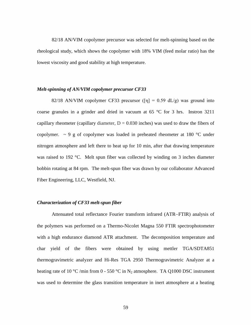
59
82/18 AN/VIM copolymer precursor was selected for melt-spinning based on the
rheological study, which shows the copolymer with 18% VIM (feed molar ratio) has the
lowest viscosity and good stability at high temperature.
Melt-spinning of AN/VIM copolymer precursor CF33
82/18 AN/VIM copolymer CF33 precursor ([η] = 0.59 dL/g) was ground into
coarse granules in a grinder and dried in vacuum at 65 °C for 3 hrs. Instron 3211
capillary rheometer (capillary diameter, D = 0.030 inches) was used to draw the fibers of
copolymer. ~ 9 g of copolymer was loaded in preheated rheometer at 180 °C under
nitrogen atmosphere and left there to heat up for 10 min, after that drawing temperature
was raised to 192 °C. Melt spun fiber was collected by winding on 3 inches diameter
bobbin rotating at 84 rpm. The melt-spun fiber was drawn by our collaborator Advanced
Fiber Engineering, LLC, Westfield, NJ.
Characterization of CF33 melt-spun fiber
Attenuated total reflectance Fourier transform infrared (ATRFTIR) analysis of
the polymers was performed on a Thermo-Nicolet Magna 550 FTIR spectrophotometer
with a high endurance diamond ATR attachment. The decomposition temperature and
char yield of the fibers were obtained by using mettler TGA/SDTA851
thermogravimetric analyzer and Hi-Res TGA 2950 Thermogravimetric Analyzer at a
heating rate of 10 °C /min from 0 - 550 °C in N2 atmosphere. TA Q1000 DSC instrument
was used to determine the glass transition temperature in inert atmosphere at a heating

60
rate of 10 °C/min. Hi-Res TGA 2950 Thermogravimetric Analyzer was used for
carbonization at 1000 °C. TA Instruments Q800 DMA was used for temperature sweep
tensile testing, which was under strain control (0.126% strain, 15 µm amplitude). The
DMA samples were heated at a rate of 2 °C/min and vibrated at a frequency of 1 Hz.
SEM 3400 S-3400N (electron beam energy 5.0 keV) and FESEM- Hitachi S4800
(electron beam energy 20.0 keV) were used to study morphology of melt-spun fibers.
Char yield testing
To study the effect of environment on stabilization, the char yields of the melt-
spun fibers were determined by TGA under two different conditions:
A. Stabilization of melt-spun fiber in air: (1) room temperature to 220 °C at10 °C
/min in air; (2) 220 °C for 3h in air; (3) 220 to 550 °C at 10 °C /min in nitrogen (N2); (4)
550 °C for 3h in N2.
B. Stabilization of melt-spun fiber in N2: (1) room temperature to 220 °C at 10
°C /min in N2; (2) 220 °C for 3h in N2; (3) 220 to 550 0C at 10 °C /min in N2; (4) 550 °C
for 3h in N2.
Preliminary carbonization study by TGA
Preliminary carbonization experiment was performed in Nitrogen (N2) under the
following carbonization procedure: (1) Ramp 10 °C /min to 700 °C; (2) Isothermal at 700
°C for 20 min; (3) Ramp 10 °C /min to 1000 °C ; (4) Isothermal at 1000 °C for 2 h.

61
CHAPTER FOUR
DISPERSION POLYMERIZATION OF POLY (ACRYLONITRILE-CO-1-
VINYLIMIDAZOLE)
Introduction
The copolymerization of acrylonitrile (AN) and 1-vinylimidazole (VIM) has been
reported by a few researchers. Poly (acrylonitrile – co -1-vinylimidazole) prepared by
60Co- γ – irradiation of AN/VIM monomer mixture was reported by Pekel at al [95].
Monomer reactivity ratios of the solution polymerization of acrylonitrile and 1-
vinylimidazole have been determined [96]. However, water-based dispersion
polymerization of acrylonitrile and 1-vinylimidazole has not been reported. Compared
with organic solvents, water has some attractive properties such as non-flammability,
non-toxicity and low cost. Water used as a medium is considered an environmentally
friendly polymerization process [97]. Unlike in emulsion polymerization, the
polymerization medium is not a solvent for the monomers; in dispersion polymerization,
the polymerization medium is a solvent for the monomers, but not a solvent for the
polymer [98].
Among those several heterogeneous polymerizations, dispersion polymerization is
a relatively new technology started in mid 1970’s [99]. Dispersion polymerization starts
as a homogeneous solution, and becomes heterogeneous during the polymerization
process, which is similar to precipitation polymerization except that the polymer product
is stabilized by the stabilizer to form controlled-size particles between 0.1-15 µm [100].

62
In general, monomers, stabilizer and initiator used in water-based dispersion
polymerization are water soluble. The location of dispersion polymerization is the water
medium, which is different from emulsion polymerization where micelle is the
polymerization location. Produced polymers nucleated together to form particle, which is
stabilized in water by stabilizer. The mechanism of particle nucleation in the dispersion
polymerization is shown in Figure 4.1 [101].
Figure 4.1 Mechanism of particle nucleation in the dispersion polymerization [101]
Stabilizers are very important to provide colloidal stablility in dispersion
polymerization. A number of block and graft copolymers were popularly used as
stablilizers [102-110]. But random copolymers become more attractive in industry
because they are synthesized more easily and affordably [111-114]. There are also

63
several homopolymers [115], such as poly (vinyl pyrrolidone) [116], hydroxyl propyl
cellulose and poly (acrylic acid) have been successfully applied as stabilizers in
dispersion polymerization [100, 117-118]. Random copolymers of acrylonitrile and 1-
vinylimidazole used as stabilizers in dispersion polymerization have not been reported.
In this study, water-based dispersion polymerization of acrylonitrile and 1-
vinylimidazole is discussed. Small amount of protonated random copolymer of
acrylonitrile and 1-vinylimidazole was used as stabilizer for synthesizing itself in
dispersion polymerization. For this application, the protonation of stabilizer copolymer
of acrylonitrile and 1-vinylimidazole is very crucial, which bring it amphiphilic nature
necessary to stabilize AN/VIM copolymer particles formed by dispersion polymerization
in water. It also overcome one drawback to remove the stabilizer incorporated in the
final product. Various copolymers with different 1-vinylimidazole content were studied
as stabilizer in acidic water of pH 1.5. The effects of stabilizer concentration and
monomer concentration on the properties of ultimate polymer particle dispersions also
have been discussed in this study.
Effect of VIM content in stabilizer on properties of the ultimate copolymer particle
prepared by dispersion polymerization
Acrylonitrile and 1-vinylimidazole were initiated by potassium persulfate
(K2S2O8). Water-based dispersion polymerization of acrylonitrile and 1-vinylimidazole is
shown in Scheme 4.1.

64
Scheme 4.1 Dispersion polymerization of AN/VIM copolymer
The statistic random copolymers of acrylonitrile and 1-vinylimidazole were
protonated in the acidic water to form stabilizers with amphiphilic nature (Scheme 4.2).
The protonation process is crucial to form valid stabilizers for the dispersion
polymerization. The protonated copolymer of acrylonitrile and 1-vinylimidazole has the
amphiphilic property, whose hydrophilic part would secure good salvation from water.
The copolymers with VIM content lower than 16% can not be dissolved well in acidic
water of pH 1.5, while the copolymers with VIM content higher than 22% can be
dissolved well. These phenomena suggest that vinylimidazole pendant group is the
location for protonation and certain amount of vinylimdazole group is necessary for
forming the valid stabilizer.
Scheme 4.2 Protonation reaction of forming AN/VIM copolymer stabilizer with
amphiphilic nature

65
Table 4.1 shows the effect of VIM content in stabilizer on the particle size and
polydispersity index of the ultimate particles by dispersion polymerization. The higher
the polydispersity index (P.I) value, the wider the particle size distribution. Since
stabilizer and monomer concentration are also the key factors for particle properties,
they were kept constant in all the dispersion polymerizations shown in table 4.1, where
the ratio of monomer to water (% w/w) is 15% and stabilizer to monomer (% w/w) is
6.8%. With the increase of the VIM content in stabilizer from 24% to 47%, the particle
size of the dispersion polymer particles decreased from 11.3 µm to 0.11 µm, and the
polydispersity index of the ultimate particles decreased from 1.44 to 1.21. The dramatic
decreasing of particle size shows protonated vinylimidazole pendant group is the key
factor for stabilizing the particles formed by dispersion polymerization in water.

66
Table 4.1 Effect of VIM content in stabilizer on the ultimate particles prepared by
dispersion polymerization
Reaction condition: 15% monomer/water (w/w), 6.8% stabilizer/monomer (w/w), 60 °C for 16h a Determined by
1H NMR
b Determined by Dynamic light scattering (DLS)
1-vinylimidazole homopolymer was also investigated in this study. In table 4.1,
very low polydispersity index 0.17 suggests almost monodispersed particles formed by
using poly (1-vinylimidazole) as a stabilizer in dispersion polymerization. The average
particle size of the ultimate particles is 0.26 µm by using poly (1-vinylimidazole) as a
stabilizer in dispersion polymerization, while the average particle size of the ultimate
particles is 0.11 µm by using P(AN-co-VIM)(53:47) as a stabilizer. Stable and fine
polymer particles were formed in both dispersions, which showed both random
copolymers of acrylonitrile and 1-vinylimidazole and 1-vinylimidazole homopolymer
can be stabilizers for dispersion polymerization in acidic water.
Sample Stabilizers* VIM content in
stabilizer (mol%)a
Particle size
Dn (µm)b
P.I.b
CF68 P(AN-co-
VIM)(76:24) 24 11.3 1.44
CF66 P(AN-co-
VIM)(69:31) 31 6.9 1.31
CF62 P(AN-co-
VIM)(53:47) 47 0.11 1.21
CF67 PVIM 100 0.26 0.17

67
Effect of stabilizer concentration on properties of the ultimate copolymer particle
prepared by dispersion polymerization
At the early stage of the dispersion polymerization of acrylonitrile and 1-
vinylimidazole, homogeneous nucleation took place in the acidic water. As the
propagation continued, the growing polymer chains exceeding a soluble critical chain
length started to form heterogeneous nucleation particles. At this stage, stabilizer
molecules were absorbed on the surface of growing copolymer particles because the
amphiphilic stabilizer tended to locate at the interface between hydrophobic polymer
surface and hydrophilic water medium. Without the amphiphilic stabilizer, the ultimate
polymer particles are not stable, having an average particle size about 29.1 µm shown in
table 4.2.
Table 4.2 Effect of stabilizer concentration on the ultimate particles
prepared by dispersion polymerization
Sample Stabilizer
concentration
(% w/w to
monomers)
Particle size
Dn (µm)a
P.I.a
CF53 0 29.1 1.46
CF55 6.8 2.6 1.74
CF61 10 0.082 0.67
CF56 13 0.063 0.47
Reaction condition: 7% monomer/water (w/w), P (AN-co-VIM) (74:26) as stabilizer
(26% VIM), 60 °C for 16h a
Determined by Dynamic light scattering (DLS)

68
The effect of stabilizer concentration on the particle size and polydispersity index
of the ultimate particles by dispersion polymerization is shown in table 4.2. With the
increase of the ratio of stabilizer to monomer from 6.8% to 13%, the particle size of the
dispersion polymer particles decreased from 2.6 µm to 0.063 µm, and the polydispersity
index of the ultimate particles decreased from 1.74 to 0.47. The sharp decreasing of
particle size and polydispersity index shows the concentration of stabilizer is very
important for forming stable polymer particles during dispersion polymerization. Small
size particles have higher surface area in total than that of bigger particles, which requires
higher amount of stabilizer molecules absorbed on their surfaces to be stabilized in water.
For the dispersion of higher ratio of stabilizer to monomer, the growing polymer particles
have enough stabilizer molecules on its surface to form fine small particles.
Since VIM content in stabilizer and monomer concentration are also the key
factors for particle properties, they were kept constant in all the dispersion
polymerizations shown in table 4.2, where the VIM content in stabilizer is 26% and the
ratio of monomer to water (% w/w) is 7%. The DLS curve of the ultimate AN/VIM
copolymer CF55 particles (P(AN-co-VIM) (74:26) as stabilizer, 6.8%
stabilizer/monomer (w/w), 7% monomer/water (w/w)) is shown in Figure 4.2.

69
Figure 4.2 DLS curve of the ultimate AN/VIM copolymer CF55 particles (P(AN-co-
VIM) (74:26) as stabilizer, 6.8% stabilizer/monomer (w/w), 7% monomer/water (w/w),
60 °C for 16h)
Effect of monomer concentration on properties of the ultimate copolymer particle
prepared by dispersion polymerization
Enough solvation from medium in dispersion polymerization is also crucial to
form stable fine polymer particles. In the dispersion with low ratio of monomer to water,
the formed polymer particles were surrounded with enough water molecules, which keep
them away from each other, so fine small particles could form. While in the dispersion
with high ratio of monomer to water, the particles did not have enough water molecules
to separate them, so the collision between polymer particles took place.
70
The effect of monomer concentration on the particle size and polydispersity index
of the ultimate particles by dispersion polymerization is shown in table 4.3. With the
increase of the ratio of monomer to water from 15% to 35%, the particle size of the
dispersion polymer particles increased from 0.11 µm to 16.3 µm. The dramatic change
of particle size shows the ratio of monomer to water is crucial to form stable polymer
particles during dispersion polymerization. Since VIM content in stabilizer and stabilizer
concentration are also the key factors for particle properties, they were kept constant in
all the dispersion polymerizations shown in table 4.3, where the VIM content in
stabilizer is 47% and the ratio of stabilizer to monomer (% w/w) is 6.8%.
Table 4.3 Effect of monomers concentration on the ultimate particles prepared by
dispersion polymerization
Sample Monomer concentration
(% w/w to water)
Particle size Dn
(µm)a
P.I.a
CF62 15 0.11 1.21
CF63 25 0.28 0.27
CF65 30 10.8 0.65
CF64 35 16.3 0.33
Reaction condition: 6.8% stabilizer/monomer (w/w), P (AN-co-VIM) (53:47) as stabilizer (47% VIM), 60
°C for 16h a Determined by Dynamic light scattering (DLS)

71
Characterization of poly (acrylonitrile – co -1-vinylimidazole) synthesized by
dispersion polymerization
Poly (acrylonitrile – co -1-vinylimidazole) synthesized by dispersion
polymerization was confirmed by 1H NMR and ATR-FTIR spectra. A typical
1H NMR
spectrum of AN/VIM copolymer CF53 is shown in Figure 4.3, Where signal δ 2.0
represents backbone CH2 from VIM and AN linkages, signal δ 3.1 represents backbone
CH from AN unit), signal δ 4.4 represents backbone CH from VIM unit and signals δ 6.9,
7.3 and 7.7 represent CH groups in imidazole ring. Figure 4.4 shows the ATR-FTIR
spectrum of AN/VIM copolymer CF53 synthesized by dispersion polymerization.
Backbone CH2 stretch at 2923 cm-1
and CN stretching at 2242 cm-1
are from AN unit.
Backbone CH2 stretching at 2923 cm-1
, C-N ring stretching at 1229 cm-1
, C-H ring in-
phase bending at 1082 cm-1
and C-N= ring stretching at 665 cm-1
are from VIM unit.

72
Figure 4.3 1H NMR spectrum of 82/18 AN/VIM copolymer CF53 (in DMSO-d6)
synthesized by dispersion polymerization

73
Figure 4.4 ATR-FTIR spectrum of AN/VIM copolymer CF53 synthesized by dispersion
polymerization
High molecular weight of poly (acrylonitrile – co -1-vinylimidazole) synthesized
by dispersion polymerization was obtained by using the recipe in experimental section
and P(AN-co-VIM) (74:26) as stabilizer, 6.8% stabilizer/monomer (w/w), 7%
monomer/water (w/w). Gel permeation chromatogram of AN/VIM copolymer CF53
(Figure 4. 5) shows the number average molecular weight (Mn) is 880,839 and
polydispersity index of molecular weight is 3.6. The AN/VIM copolymer synthesized by
dispersion polymerization has a discomposition temperature around 300 °C detected by
TGA.

74
Figure 4.5 Gel permeation chromatogram of AN/VIM copolymer CF53 synthesized by
dispersion polymerization (polystyrene standard, in DMF)
Conclusions
Poly (acrylonitrile – co -1-vinylimidazole) was successfully synthesized by
dispersion polymerization, which was confirmed by 1H NMR and ATR-FTIR spectra.
Controlled-size particles were obtained by using random copolymer of acrylonitrile and
1-vinylimidazole as a stabilizer in dispersion polymerization in acidic water of pH 1.5.
The vinylimidazole pendant group is the location for protonation and above 22% VIM in
copolymer is necessary for forming a valid stabilizer. The effects of stabilizer
concentration and monomer concentration on the particle size and polydispersity index of
the ultimate particles by dispersion polymerization have been studied. With the increase

75
of the ratio of stabilizer to monomer from 6.8% to 13%, the particle size of the dispersion
polymer particles decreased from 2.6 µm to 0.063 µm, and the polydispersity index of the
ultimate particles decreased from 1.74 to 0.47. With the increase of the ratio of monomer
to water from 15% to 35%, the particle size of the dispersion polymer particles increased
from 0.11 µm to 16.3 µm. The protonated poly (acrylonitrile – co -1-vinylimidazole) can
be a novel stabilizer for dispersion polymerization.
Experimental
Materials
Potassium persulfate, 1-vinylimidazole (VIM), acrylonitrile (AN), acetic acid,
2,2’-Azobis(2-methylpropionitrile) (AIBN), N,N-dimethylformamide (DMF) and 1-
Dodecanethiol were purchased from the Aldrich Chemical Co. All reagents were used as
received.
Synthesis of polymeric stabilizers
Random copolymers of acrylonitrile and 1-vinylimidazole were prepared as
stabilizers for dispersion polymerization. The solution polymerization of AN and VIM
by varying feed ratio was carried out in a reaction flask fitted with a thermocouple probe,
condenser, addition funnel and nitrogen inlet. The flask was charged with solvent DMF
and purged with nitrogen for 30 min. Then the monomers, AIBN and chain transfer
agent, 1-dodecanethiol were added drop wise into the flask over a period of 2-5 h. The
polymerization reactions were carried at 70 °C with continuous stirring. The copolymer

76
was precipitated in excess de-ionized water, filtered and washed with methanol and
hexane to remove residual monomers and then dried in vacuum oven for two days till
constant weight was obtained. 1H NMR spectrum (DMSO-d6) of AN/VIM copolymer
stabilizer: δ 2.0 (backbone CH2 from VIM and AN linkages), δ 3.1 (backbone CH from
AN unit), δ 4.4 (backbone CH from VIM unit) and δ 7.8- 6.8 (CH groups in imidazole
ring).
Dispersion polymerization of acrylonitrile and 1-vinylimidazole copolymers CF52-67
The pH of de-ionized water was adjusted to 1.5 by acetic acid. Stabilizers were
dissolved in the acidic water in the reaction flask fitted with a thermocouple probe,
condenser, addition funnel and nitrogen inlet at 60 °C. Potassium persulfate (0.014 g)
was added into the flask. Then acrylonitrile (2.2 g) and 1-vinylimidazole (0.85 g)
mixture was added drop wise into the flask within 1 h. The dispersion polymerization
was carried at 60 °C with continuous stirring for 16 h. The copolymer dispersion was
neutralized by potassium hydroxide. The precipitated copolymer was filtered and washed
with methanol and hexane to remove residual monomers and then dried in vacuum oven
for two days till constant weight was obtained.
Characterization of AN/VIM copolymers
1H NMR spectrum was obtained by JEOL ECX-300 spectrometer using DMSO-d6
as solvent. Size exclusion chromatography (SEC) was used to determine the molecular
weights of polymers in N,N-dimethyformamide (DMF) at 50 °C at 1 mL/min flow rate on

77
a Waters SEC instrument equipped with two Waters Styragel HR5E (DMF) columns, a
Waters 717 plus autosampler, a Waters 2414 differential refractive index detector and a
Wyatt Technologies miniDAWN multiangle laser light scattering (MALLS) detector.
Coulter N4MD Sub-Micron Particle Analyzer was used to determine particle size and
distribution of the copolymer dispersion and the data shown in the table is the average of
three repeated test values. Attenuated total reflectance Fourier transform infrared
(ATRFTIR) analysis of the copolymer was performed on a Thermo-Nicolet Magna 550
FTIR spectrophotometer with a high endurance diamond ATR attachment. The thermal
stability of the copolymer was performed by using Mettler-Toledo 851 thermogravimetric
analyzer.

78
CHAPTER FIVE
POLY (ACRYLONITRILE-CO-1-VINYLIMIDAZOLIUM TETRAFLUOROBORATE)
AND POLY (ACRYLONITRILE-CO-1-VINYLIMIDAZOLIUM
HEXAFLUOROPHOSPHATE) FOR GAS SEPARATION MEMBRANES
Introduction
The most commercially utilized membranes in separation industry are made of
polymers [119, 120]. The polymer has to be a suitable membrane former in terms of its
chain rigidity, chain interactions and polarity [121, 122]. The polymer also needs to be
able to form stable, thin and low-cost membrane. Polysulfone, polyimide, cellulose
acetate, polyphenylene oxide and silicone rubber are the principle commercially used
polymer membrane materials [123]. Figure 5.1 shows the structure of a typical
anisotropic gas separation membrane. The top selective layer is very thin (less than 5
µm) and has fine pores with the size in range of 100-200 Å [123].
Figure 5.1 The structure of a typical anisotropic gas separation membrane (Reprinted
with permission from Baker R W. Ind Eng Chem Res 2002; 41: 1393-1411, Copyright ©
2002 American Chemical Society under the license number 2550960473514) [123]

79
Closely packed polymer chains tend to give better selectivity, at the cost of
permeability (P). Robeson has illustrated the inverse selectivity/permeability relationship
of polymer membranes in 1991. The plot of oxygen/nitrogen selectivity as a function of
oxygen permeability for polymer membranes is shown in Figure 5.2 [123]. It depicts the
trade off between selectivity and permeability. There are also cobalt carrier facilitated
transport membranes in the plot showing one promising type of membranes. The
structure of cobalt carrier membrane polymer is shown in Figure 5.3 [123]. The cobalt
complex is chemically bond to the polymer backbone and functions as the oxygen carrier
to improve both permeability and selectivity of oxygen.
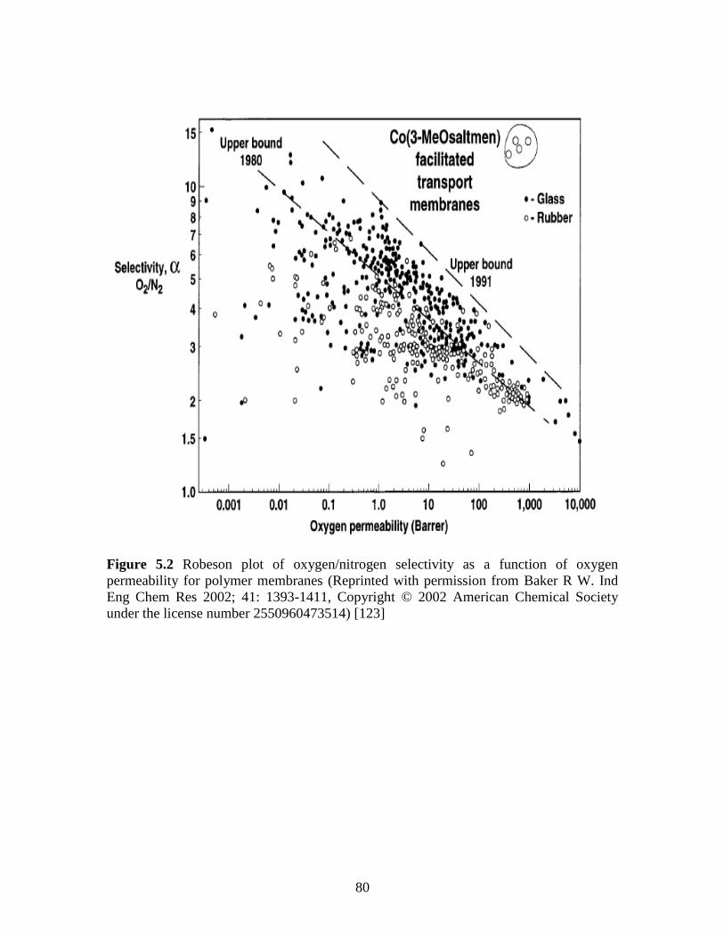
80
Figure 5.2 Robeson plot of oxygen/nitrogen selectivity as a function of oxygen
permeability for polymer membranes (Reprinted with permission from Baker R W. Ind
Eng Chem Res 2002; 41: 1393-1411, Copyright © 2002 American Chemical Society
under the license number 2550960473514) [123]

81
Figure 5.3 Structure of cobalt carrier membrane polymer (Reprinted with permission
from Baker R W. Ind Eng Chem Res 2002; 41: 1393-1411, Copyright © 2002 American
Chemical Society under the license number 2550960473514) [123]
Permeability and selectivity of polymeric membranes still low and need to be
improved. For example, polyimides are one type of widely used polymers for gas
separation membranes. Membranes made of polyimides with different structures show
different permeabilities and selectivities of gases. One research showed P(CO2) of the
polyimide membrane is 42.7 barrer and selectivity α(CO2/N2) is 16 [124]. Another
research showed P(CO2) of the polyimide membrane is 27 barrer and selectivity
α(CO2/N2) is 33 [125]. Whereas, certain imidazolium-based supported ionic liquid
membranes (SILMs) have shown CO2 permeabilities near 1000 barrers and selectivities
for CO2/ N2 greater than 50 [126].
SILMs are a class of supported liquid membranes composed of room-temperature
ionic liquids (RTILs) encapsulated within a polymeric support. SILMs show higher
permeabilities and selectivities than polymeric membranes. However, SILMs lack robust

82
stability and are subject to break under moderate pressures [126]. Polymerized room-
temperature ionic liquids (poly(RTILs)) are developed to overcome the limitations of
supported ionic liquid membranes (SILMs). Imidazolium cations are bound to the
polymer backbone while anions not covalently bound to the polymer. Poly(RTILs ) are
more stable and can be performed under higher pressures. In this study, poly
(acrylonitrile – co -1-vinylimidazolium tetrafluoroborate) and poly (acrylonitrile – co-1-
vinylimidazolium hexafluorophosphate) membranes were applied for gas separation,
which has not been reported.
Synthesis and characterization
The schematic representation for the synthesis of poly (acrylonitrile – co -1-
vinylimidazolium tetrafluoroborate) and poly (acrylonitrile – co -1-vinylimidazolium
hexafluorophosphate) is shown in Scheme 5.1.

83
Scheme 5.1 Synthesis of poly (acrylonitrile – co -1-vinylimidazolium tetrafluoroborate)
and poly (acrylonitrile – co -1-vinylimidazolium hexafluorophosphate)
Poly (acrylonitrile – co -1-vinylimidazolium tetrafluoroborate) and poly
(acrylonitrile – co -1-vinylimidazolium hexafluorophosphate) synthesized were
confirmed by ATR-FTIR and 19
F NMR spectra. Figure 5.4 shows the ATR-FTIR
spectrum of Poly (acrylonitrile – co -1-vinylimidazolium tetrafluoroborate) IL4.
Backbone CH2 stretch at 2929 cm-1
and CN stretching at 2240 cm-1
are from AN unit. C-
H ring stretching at 3109 cm-1
, backbone CH2 stretching at 2929 cm-1
, C-N ring stretching
at 1229 cm-1
, and C-N= ring stretching at 665 cm-1
are from VIM unit. The peak at 1057
cm-1
is corresponding to the v(BF4) vibration [127, 128].

84
Figure 5.4 ATR-IR spectrum of poly (acrylonitrile – co -1-vinylimidazolium
tetrafluoroborate) IL4

85
Figure 5.5 ATR-IR spectrum of poly (acrylonitrile – co -1-vinylimidazolium
hexafluorophosphate) IL6
Figure 5.5 shows the ATR-FTIR spectrum of Poly (acrylonitrile – co -1-
vinylimidazolium hexafluorophosphate) IL6. Backbone CH2 stretch at 2962 cm-1
and
CN stretching at 2242 cm-1
are from AN unit. C-H ring stretching at 3118 cm-1
,
backbone CH2 stretching at 2962 cm-1
, C-N ring stretching at 1229 cm-1
, and C-N= ring
stretching at 665 cm-1
are from VIM unit. The peak at 837 cm
-1 is corresponding to the
v(PF6) vibration [129].

86
Figure 5.6 19
F NMR of poly (acrylonitrile – co -1-vinylimidazolium tetrafluoroborate)
IL4 in DMSO-d6
A 19
F NMR spectrum of poly (acrylonitrile – co -1-vinylimidazolium
tetrafluoroborate) IL4 is shown in Figure 5.6. In 19
F NMR spectra (DMSO-d6), signal at
δ –148.0 ppm represents 4F from BF4 [130]. A 19
F NMR spectrum of poly (acrylonitrile
– co -1-vinylimidazolium hexafluorophosphate) IL6 is shown in Figure 5.7. In 19
F NMR
spectra (DMSO-d6), signals at δ-68.7 and -71.2 ppm represent 6F from PF6. The splitting
is due to the spin-spin coupling of 19
F and 31
P [131].

87
Figure 5.7 19
F NMR of poly (acrylonitrile – co -1-vinylimidazolium
hexafluorophosphate) IL6 in DMSO-d6
Gas separation performances of poly (acrylonitrile – co -1-vinylimidazolium
tetrafluoroborate) and poly (acrylonitrile – co -1-vinylimidazolium
hexafluorophosphate) membranes
Photos of poly (acrylonitrile – co -1-vinylimidazolium tetrafluoroborate) IL4 and
poly (acrylonitrile – co -1-vinylimidazolium hexafluorophosphate) IL6 membranes used
for gas separation are shown in Figure 5.8. They are transparent thin films.

88
Figure 5.8 Poly (acrylonitrile – co -1-vinylimidazolium tetrafluroborate) IL4 membrane
used for gas separation (left); poly (acrylonitrile – co -1-vinylimidazolium
hexafluorophosphate) IL6 membrane used for gas separation (right) . Both were made
by Adam T. Haldeman in Tetramer Technologies, L.L.C)
Permeabilities of poly (acrylonitrile – co -1-vinylimidazolium tetrafluoroborate)
IL4 and poly (acrylonitrile – co -1-vinylimidazolium hexafluorophosphate) IL6
membranes were tested by Adam T. Haldeman in Tetramer Technologies, L.L.C and
shown in table 5.1. The low selectivities indicate that the permeance measured primarily
through micro-voids rather than intermolecular free volume. And it also indicates the
intrinsic permeabilities of the polymers are low.

89
Table 5.1 Gas separation performances of permeabilities of poly (acrylonitrile – co -1-
vinylimidazolium tetrafluoroborate) IL4 and poly (acrylonitrile – co -1-vinylimidazolium
hexafluorophosphate) membranes IL6
Memb-
rane
Permeabilities (Barrer) Selectivities Thick-
ness
(cm) CF47
(refere
nce)
N2 O2 CH4 H2 CO2 O2/
N2
CO2/
CH4
H2/
CO2
21525 20694 27802 81208 17057 1.0 0.6 4.8 0.0045
178659 198510 282688 920922 N/A 1.1 0.6 5.2 0.0025
21375 20654 29776 97009 18806 1.0 0.6 5.2 0.0015
10136 11812 16571 47563 11079 1.2 0.7 4.3 0.004
CF47-
BF4
(IL4)
N/A N/A N/A N/A N/A 0.00535
9.7 10.8 15.6 31.8 16.3 1.1 1.0 2.0 0.0023
CF47-
PF6
(IL6)
N/A N/A N/A 2505 618 4.1 0.004
702 591 871 2246 400 0.8 0.5 5.6 0.004
469 155 392 468 89 0.3 0.2 5.2 0.0013
Conclusions
Poly (acrylonitrile – co -1-vinylimidazolium tetrafluoroborate) and poly
(acrylonitrile – co -1-vinylimidazolium hexafluorophosphate) were successfully
synthesized and confirmed by ATR-FTIR and 19
F NMR spectra. Membranes made of
them were applied for gas separation.
Experimental
Materials

90
1-Chlorobutane, Potassium tetrafluoroborate (KBF4), Potassium
hexafluorophosphate (KPF6), acetonitrile (MeCN), 2,2’-Azobis(2-methylpropionitrile)
(AIBN), 1-vinylimidazole (VIM), acrylonitrile(AN), N,N-dimethylformamide (DMF),
dimethyl sulfoxide (DMSO) and 1-Dodecanethiol were purchased from the Aldrich
Chemical Co. All reagents were used as received.
Synthesis of poly (acrylonitrile – co -1-vinylimidazolium tetrafluoroborate) IL4 and
poly (acrylonitrile – co -1-vinylimidazolium hexafluorophosphate) IL6
The solution polymerization of AN and VIM was carried out in a 250 mL flask
fitted with a thermocouple probe, condenser, addition funnel and nitrogen inlet. The
flask was charged with DMF and purged with nitrogen for 30 min. The monomers (AN
and VIM with molar ratio of 82 to 18), AIBN and 1-dodecanethiol were added drop wise
into the flask for 5 hrs. The polymerization was carried out at 70 °C with continuous
stirring for 16 h. Then 1-Chlorobutane and acetonitrile were added in the polymer
solution. The reaction was carried out at 75 °C for 48 hrs. Poly (acrylonitrile – co -1-
vinylimidazolium chloride) was precipitated in toluene, filtered and washed with
methanol and hexane and then dried in vacuum oven for two days till constant weight
was obtained.
Potassium tetrafluoroborate (KBF4) and poly (acrylonitrile – co -1-
vinylimidazolium chloride) were added in the flask charged with DMSO. The ion
exchange reaction was carried out at 60-65 °C for 8 hrs. Poly (acrylonitrile – co -1-
vinylimidazolium tetrafluoroborate) IL4 was precipitated in excess de-ionized water,

91
filtered and washed with methanol and hexane and then dried in vacuum oven for two
days till constant weight was obtained.
Potassium hexafluorophosphate (KPF6) and poly (acrylonitrile – co -1-
vinylimidazolium chloride) were added in the flask charged with DMSO. The ion
exchange reaction was carried out at 60-65 °C for 10 hrs. Poly (acrylonitrile – co -1-
vinylimidazolium hexafluorophosphate) IL6 was precipitated in excess de-ionized water,
filtered and washed with methanol and hexane and then dried in vacuum oven for two
days till constant weight was obtained.
Characterization
Thermo-Nicolet Magna 550 FTIR spectrophotometer was used for ATR-IR
analysis of polymers. 19
F NMR spectra were obtained with JEOL ECX-300
spectrometer using DMSO-d6 as solvent.
Procedure for making poly (acrylonitrile – co -1-vinylimidazolium tetrafluoroborate) and
poly (acrylonitrile – co -1-vinylimidazolium hexafluorophosphate) membranes (Adam T.
Haldeman, Scientist in Tetramer Technologies, L.L.C)
Poly (acrylonitrile – co -1-vinylimidazolium tetrafluoroborate) and poly
(acrylonitrile – co -1-vinylimidazolium hexafluorophosphate) membranes were made by
Adam T. Haldeman in Tetramer Technologies, L.L.C. ~10wt% polymer solution (DMF
as solvent) was used for casting membrane onto a silicon wafer. The wafer was then
covered with a lid with a small hole on the top to limit solvent evaporation rate. The

92
wafer was then heated to 80 °C for 4 hrs to slowly evaporate the solvent. Then the
membrane was washed by CHCl3 and put in an oven at 80 °C overnight in order to drive
off residual solvent.
Gas separation experiment
Figure 5.9 A photo of the gas permeance testing panel showing the test cell in the center
of the panel and the bubble-flow meter to the right of the panel (in Tetramer
Technologies, L.L.C)
Gas separation experiments were performed by Adam T. Haldeman in Tetramer
Technologies, L.L.C. A homemade measurement panel (Figure 5.9) was used to
characterize membranes in order to identify promising polymers for further investigation

93
and optimization. The system applied a gas at a given pressure to the feed side of the
membrane, and as gas passed through the membrane, it pushed a bubble through a flow
meter on the opposite side (permeate side) of the membrane. The testing temperature is
25 °C. Circular stamps with 1.5 inch diameters were first cut from each membrane for
testing in the gas permeance panel. Once a stamp was sealed in the instrument’s cell,
nitrogen at 100 psi was applied to the testing cell. The system was given 10 minutes to
equilibrate at that pressure before any measurements were taken in order to ensure
steady-state conditions. The selectivity of one gas over another was taken as the relative
ratio of their permeances.

94
CHAPTER SIX
UV-CURABLE OPTICAL FIBER COATINGS
Introduction
Silica-based optical fibers are widely used in telecommunication systems [132-
135]. A polymeric coating is applied to optical fibers to shield glass from scratches
which can result in fiber damage. The elastomeric coatings provide mechanical
protection to the pristine surface of the glass fiber. The acrylate coatings can be cured at
high speeds by ultraviolet (UV) light, which provides high production rates. Also the
coatings have properties ranging from soft and elastic to hard and tough [136, 137].
Acrylic coated fibers are durable, providing years of high performance service [138,
139]. Figure 6.1 shows the drawing, coating and UV curing processes of the optic fiber.

95
Figure 6.1 The drawing, coating and UV curing processes of the optical fiber
However, as fibers used in extreme environments, such as down-hole monitoring
of oil wells, the greater thermal stability of optical fiber is required. There is a growing
need for coatings that withstand higher temperature and does not change (much) their
existing process. In this study, the method of improving the thermal stability of optical
fiber is to add a multi-fuctional monomer (penta-acrylate in Figure 6.2) to increase the
cross-linking of the polymeric coating. I worked with Stephen Budy on this project.

96
Figure 6.2 Structure of dipentaerythritol penta-acrylate (purchased from Aldrich
Chemical Co.)
Thermal stability
Thermal stability of the polymeric coating was examined by TGA at a heating
rate of 10 °C /min in N2 and air. Degradation temperature increased as DeSolite coating
#3471-3-14 was added with dipentaerythritol penta-/hexa-acrylate. Figure 6.3 shows the
thermogram of blended UV coatings of DeSolite #3471-3-14 with different percentage of
dipentaerythritol penta-/hexa-acrylate in N2 [140]. DSM DeSolite #3471-3-14 coating
has an early degradation around 140 °C, and sharp degradation at 248 °C in N2. As
dipentaerythritol penta-/hexa-acrylate added in DSM DeSolite #3471-3-14, even 1%, the
early degradation disappeared. The sharp degradation of blended DeSolite #3471-3-14
and 1% dipentaerythritol penta-/hexa-acrylate started at 287 °C. With the increase of
weight percentage of dipentaerythritol penta-/hexa-acrylate in the blended coating, the
degradation temperature increased. The blended coatings with 40% and 60%
dipentaerythritol penta-/hexa-acrylate began to degrade at 305 °C and 312 °C,
respectively, and the degradations are much slower than that of DeSolite #3471-3-14. At

97
450 °C, the blended coating of DeSolite #3471-3-14 with 60% dipentaerythritol penta-
/hexa-acrylate had a weight loss around 20%.
Figure 6.3 Thermogram of UV coatings of DeSolite #3471-3-14 with different
percentage of dipentaerythritol penta-/hexa-acrylate (10 °C/min, in N2)
Figure 6.4 is the thermogram of UV coatings of DeSolite #3471-3-14 with
different percentage of dipentaerythritol penta-/hexa-acrylate in air. DSM DeSolite
#3471-3-14 coating has an early degradation around 137 °C, and sharp degradation at
231 °C in air. As dipentaerythritol penta-/hexa-acrylate added in DSM DeSolite #3471-
3-14, the early degradation also disappeared in air. The sharp degradation of blended
DeSolite #3471-3-14 and 1% dipentaerythritol penta-/hexa-acrylate started at 285 °C in
air. With the increase of weight percentage of dipentaerythritol penta-/hexa-acrylate in

98
the blended coating, the degradation temperature increased. The blended coatings with
40% and 60% dipentaerythritol penta-/hexa-acrylate began to degrade at 296 °C and 307
°C in air, respectively.
Figure 6.4 Thermogram of UV coatings of DeSolite #3471-3-14 with different
percentage of dipentaerythritol penta-/hexa-acrylate (10 °C/min, in air)
Figure 6.5 shows the dependence of degradation temperature of UV coatings on
weight percentage of dipentaerythritol penta-/hexa-acrylate in N2 and in air. The coatings
intended to decrease at lower temperature in air than in N2. Even with1%
dipentaerythritol penta-/hexa-acrylate added in DeSolite #3471-3-14, the degradation
temperature increased 39 °C in N2 and 54 °C in air. Dipentaerythritol penta-/hexa-

99
acrylate has high cross-linking functionality, which would increase the cross-linking
degree of the system, and result in better thermal stability of commercial DSM DeSolite
#3471-3-14.
Figure 6.5 Dependence of degradation temperature of UV coatings on weight percentage
of dipentaerythritol penta-/hexa-acrylate (10 °C/min)
Flexibility
Fiber coatings need to exhibit greater thermal stability without damaging other
properties. In some cases, high functional cross-linker would damage the flexibility
when increase cross-linking. In this study, spin coated films of DeSolite #3471-3-14 with
different percentage of dipentaerythritol penta-/hexa-acrylate on transparency were bent
180 degree. The films with 5-25% dipentaerythritol penta-/hexa-acrylate showed good

100
flexibility with no fracture (table 6.1). But the film with 40% dipentaerythritol penta-
/hexa-acrylate showed some fracture. So lower than 25% dipentaerythritol penta-/hexa-
acrylate can be added in DeSolite #3471-3-14 to form good flexible fiber coatings.
Table 6.1 Flexibility of UV coatings of DeSolite #3471-3-14 with different
percentage of dipentaerythritol penta-/hexa-acrylate
Weight percentage of the high functional
acrylate
Flexibility
5 Good
8 Good
10 Good
12 Good
15 Good
18 Good
20 Good
25 Good
40 Bad
Conclusion
UV-curable DeSolite #3471-3-14 with 1-25% dipentaerythritol penta-/hexa-
acrylate exhibits great thermal stability and good flexibility, which are very useful in the
extreme environments, where fiber coatings withstand high temperature is required.
Experimental
Materials

101
DeSolite coating #3471-3-14, a UV-curable acrylate resin, was purchased from
DSM DeSolite, Inc. Dipentaerythritol penta-/hexa-acrylate was purchased from Aldrich
Chemical Co. and used as received.
Experimental
DeSolite coating #3471-3-14 was blended with different weight percentage of
Dipentaerythritol penta-/hexa-functional acrylate to form uniform mixture. Spin coating
was used to make the film of the mixture. The film was cured under a UV lamp.
Thermal stability of the polymeric coating was examined by Hi-Res TGA 2950
Thermogravimetric Analyzer at a heating rate of 10 °C /min in N2 and air.

102
CHAPTER SEVEN
THERMO-REVERSIBLE METHYL METHACRYLATE-METHYL ACRYLATE-
FURFURYL METHACRYLATE (MMA/MA/FMA) AND BISMALEIMIDE (BMI)
CROSS-LINKED POLYMER
Introduction
Cross-linking brings good mechanical property, heat and chemical resistances to
polymers. However, one major drawback of cross-linked polymers is lack of re-
fabrication ability [141]. Polymers that can be reversibly cross-linked through covalent
bonds are of much current research interest from the standpoints of recycling,
processability, self-repairing and re-fabrication [142-144]. The Diels-Alder (DA)
reaction is one, which is known to generate thermo-reversible cross-linking. The
covalent bond (adduct) formed by DA reaction can be easily broken down to diene and
dienophile [145-148]. DA reaction in polymer cross-linking brings a new class of
thermally-reversible cross-linked polymers [149-158].
The DA reaction of maleimide and Furan-functionalized polymer bringing
thermo-reversible cross-linking ability to product has been discussed by some researchers
[159-161]. But to the best of our knowledge, emulsion polymerization of methyl
methacrylate - methyl acrylate - furfuryl methacrylate (MMA/MA/FMA) terpolymer has
not been reported so far. In this research, terpolymers of methyl methacrylate, meth
acrylate and furfuryl methacrylate were synthesized successfully by solution
polymerization and emulsion polymerization and were characterized by 1H NMR, ATR-

103
IR and DSC. Emulsion polymerization is a type of radical polymerization which is
widely used in industry, which generally starts with an emulsion incorporating water,
monomer, and surfactant [163]. Figure 7.1 shows the general mechanism of the
emulsion polymerization. There are several advantages of using it: low cost process,
nonflammable, and environmentally friendly water. Also, excessive exothermic effects
can be minimized by the dispersing medium [164]. This polymer emulsion used as resin
can low its cost and widen its application.
Figure 7.1 General mechanism of emulsion polymerization (Reprinted with permission
from its author Firesine for free license under the Creative Commons Attribution-
ShareAlike License) [163]
The MMA/MA/FMA terpolymer showed tunable Tg by adjusting feed molar ratio
of soft monomer MA and stiffer monomer MMA, which is useful for the prosthetic

104
application. The furfuryl methacrylate unit in MMA/MA/FMA terpolymer can be cross-
linked with bismaleimide (BMI) and generate the thermo-reversible cross-linked polymer
by DA chemistry. It can be applied for making thermally re-moldable carbon fiber
composite. In current prosthetic technology, when body heals and limb adding to the
discomfort to the patient, the carbon fiber composite must be replaced by new one, which
leads to high cost. The MMA/MA/FMA and BMI cross-linked polymer emulsion can be
used as resin to replace the current epoxy and amine system.
Characterization of MA/MMA/FMA terpolymer
In
this research,
terpolymers of methyl methacrylate, methyl acrylate and furfuryl
methacrylate (MMA/MA/FMA) were synthesized successfully by solution
polymerization and emulsion polymerization. The furan-functionalized terpolymer was
thermally cross-linked with bismaleimide (BMI) at low temperature 55 ºC; while
thermally reversible uncrosslinking was accomplished at 130 ºC (Scheme 7.1).

105
Scheme7.1 Diels-Alder and retro Diels-Alder reactions of MA/MMA/FMA terpolymer
with BMI
1H NMR (300MHz, DMSO-d6) of MA/MMA/FMA terpolymer TR1 is shown in
Figure 7.2 where signals at δ 6.4 and δ 7.2 represent furfuryl protons, signal at δ 3.5

106
represents -OCH3 protons in MMA and MA. Figure 7.3 shows the ATR-FTIR spectrum
of MA/MMA/FMA terpolymer TR1. C-C stretch (in-ring) at 1435 cm-1
and C-H out-of-
plane bend at 750 cm-1
from FMA unit were observed; C=O stretch at 1724 cm-1
, C-O
stretch at 1139 cm-1
, and C-H stretch at 2950-2990 cm
-1from MA, MMA and FMA were
clearly shown. The molecular weight of MA/MMA/FMA terpolymer TR1 determined
by GPC showed a broad distribution. A typical GPC curve of MA/MMA/FMA
terpolymer TR1 is shown in Figure 7.4, which has an average number molecular weight
of 27,022 and weight distribution index (PDI) of 4.1. Figure 7.5 shows the
decomposition temperature of MA/MMA/FMA terpolymer TR1 is around 337 ºC in N2;
while 310 ºC in air. It is one-step sharp decomposition, having a weight loss of 95% at
about 440 ºC in N2; while 90% at 445 ºC in air. Oxygen in air could accelerate the
decomposition of this MA/MMA/FMA terpolymer.
Figure 7.2 1H NMR of MA/MMA/FMA terpolymer TR1 (in DMSO-d6)

107
Figure 7.3 ATR-IR spectrum of MA/MMA/FMA terpolymer TR1

108
Figure 7.4 Gel permeation chromatogram of MA/MMA/FMA terpolymer TR1
(polystyrene standard, in THF)
Figure 7.5 TGA thermograms of MA/MMA/FMA and BMI cross-linked polymer CR1
and MA/MMA/FMA terpolymer TR1 (10 °C/min, in N2 and air)

109
Previous research indicated that high amount of FMA would lead to insoluble
polymer [148], and even 3-5% furfuryl functional group can bring effective cross-linking
property [149]. Based on these previous results, 15% molar ratio of FMA was chosen to
be fed in all the polymerizations of terpolymer in this research. Molar ratio of MMA and
MA was adjusted to tune the glass transition temperature (Tg) of MA/MMA/FMA
terpolymer. Table 7.1 shows three typical glass transition tempertures of the terpolymer
with three different feed molar ratios of MA and MMA. High amount of MA added
would decrease Tg of the terpolymer due to the soft nature of MA; while high amount of
MMA added would raise Tg of the terpolymer because MMA is a stiff monomer.
Tunable Tg of the terpolymer was obtained by adjusting the feed molar ratio of soft
monomer MA and stiffer monomer MMA, which is useful for the prosthetic application.
Table 7.1 Composition and glass transiton temperature of MA/MMA/FMA
terpolymer
MA
(Feed mol %)
MMA
(Feed mol %)
FMA
(Feed mol %)
Tg of
MA/MMA/FMA
terpolymer (ºC) *
55 30 15 57
45 40 15 82
30 55 15 103
*TA Q1000 DSC (10 °C/min, in N2)

110
Characterization of MA/MMA/FMA and BMI cross-linked polymer
MA/MMA/FMA and BMI cross-linked polymer emulsion CR4 has a particle size
around 5870 nm and polydispersity index (P.I.) about 1.06 (Figure 7.6); while
MA/MMA/FMA terpolymer emulsion TR4 has a particle size of 119 nm and P.I. about
0.051 (Figure 7.7). The sharp increase of particle size of the cross-linked polymer
emulsion is due to the DA reaction of FMA and BMI, which linked the terpolymer
particles together to form bigger cross-linked polymer particles. Thermal
characterization of MA/MMA/FMA and BMI cross-linked polymer showed different
properties from that of MA/MMA/FMA terpolymer. The cross-linked polymer CR1 has
an earlier decomposition started around 136 ºC in air & N2 in TGA thermogram (Figure
7.5), and a new transition at 139 ºC in DSC thermogram (Figure 7.8), which can be
uncross-linking of the polymer caused by retro-DA reaction.
Figure 7.6 Particle size and distribution of MA/MMA/FMA and BMI cross-linked
polymer emulsion CR4 by DLS

111
Figure 7.7 Particle size and distribution of MA/MMA/FMA terpolymer emulsion TR4
by DLS
Figure 7.8 DSC thermogram of MA/MMA/FMA and BMI cross-linked polymer CR1
(10 °C/min, in N2)

112
Thermo-reversible property of MA/MMA/FMA and BMI cross-linked polymer
Attenuated total reflectance Fourier transform infrared (ATRFTIR) was used to
observe the thermo-reversible property of MA/MMA/FMA and BMI cross-linked
polymer. ATR-IR spectrum of the cross-linked polymer CR1 (Figure 7.9 b) has a peak
at 1674 cm-1
, from C=C in adduct of cross-linked polymer, which indicates that (4+2)
cycloaddition took place between furfuryl group in MA/MMA/FMA terpolymer and
BMI. This peak disappeared after the cross-linked polymer being heated at high
temperature and quenched by liquid N2 to freeze its structure (Figure 7.10 a). The
disappearance of peak 1674 cm-1
is due to the uncross-linking by retro Diels-Alder (rDA)
reaction. Once the uncross-linked polymer was heated again and cooled slowly by air,
the peak 1677 cm-1
was shown again in
ATR-IR spectrum (Figure 7.10 b), which
indicates that (4+2) cycloaddition took place again by DA chemistry. Cross-linked
MA/MMA/FMA and BMI polymer can be easily uncross-linked and recross-linked by
DA and retro-DA reactions.

113
Figure 7.9 ATR-IR spectra of: a) MA/MMA/FMA terpolymer TR1; b) MA/MMA/FMA
and BMI cross-linked polymer CR1

114
Figure 7.10 ATR-IR spectra of: a) uncross-linked MA/MMA/FMA terpolymer with BMI;
b) MA/MMA/FMA and BMI recross-linked polymer
Thermo-reversible properties of MA/MMA/FMA and BMI cross-linked polymers
CR1 and CR4 were also confirmed by solubility test. MA/MMA/FMA and BMI cross-
linked polymer CR1 would be uncross-linked after being heated at 130-136 ºC in DMF
for 2 h and shown as a clear solution (Figure 7.11 a); While the cross-linked polymer gel
was insoluble in DMF at room temperature even after one month (Figure 7.11 b). This
experiment showed Diel-Alder (DA) and retro Diels-Alder (rDA) reactions did take place
between MA/MMA/FMA terpolymer and BMI.

115
Figure 7.11 (a) Cross-linked polymer CR1 (left) and uncross-linked polymer solution
after being heated at 130 ºC in DMF (right); (b) Insoluble cross-linked polymer gel after
one month in DMF at room temperature.
Remolding experiments
Cross-linked MA/MMA/FMA and BMI polymer CR1 would become very soft
after being heated about 2 min by heat gun. It could be easily molded to various shapes
when it was hot. When cooling down, the polymer became stiff, and maintained its shape
at room temperature. This heating and cooling process could be repeated 7 cycles
without damaging the polymer. But after 9 cycles, the polymer color became darker.
Figure 7.12 shows various shapes of cross-linked MA/MMA/FMA and BMI polymer
CR1 after being heated and remolded. The property is very useful for making thermo-
remoldabe carbon fiber composite.

116
Figure 7.12 Re-molding experiment of MA/MMA/FMA and BMI cross-linked polymer
CR1
MA/MMA/FMA and BMI cross-linked polymer emulsion CR4 was used as resin
to produce thermo-remoldable carbon fiber composite in this study. Carbon fiber cloth
was filled with MA/MMA/FMA and BMI cross-linked polymer emulsion CR4 and
heated at 70 ºC to form carbon fiber composite. The composite obtained could be
molded to various shapes when it was hot. After cooling down, the composite
maintained its shape at room temperature. Figure 7.13 shows various shapes of carbon
fiber composite after being heated and remolded. This MA/MMA/FMA and BMI cross-
linked polymer emulsion has the potential application as the resin to replace epoxy and
amine system for carbon fiber composite and lower the cost in prosthetic industry.

117
Figure 7.13 Re-molding experiment of MA/MMA/FMA and BMI resin CR4 carbon
fiber composite
Conclusions
A novel MA/MMA/FMA terpolymer was synthesized by solution polymerization
and emulsion polymerization. Thermo-reversible cross-linking via DA and retro-DA
reactions between the terpolymer and BMI was confirmed by ATR-IR and solubility
tests. The cross-linked polymer showed a quick remolding ability. MA/MMA/FMA and
BMI cross-linked polymer emulsion has the potential to replace epoxy and amine system
for carbon fiber composite and lower the cost in prosthetic industry.
Experimental
Materials
Methyl acrylate (MA), Methyl methacrylate (MMA), furfuryl methacrylate
(FMA), 2,2’-Azobis(2-methylpropionitrile) (AIBN), N,N'-1,3-phenylenedimaleimide

118
(BMI), Ammonium persulfate, Sodium dodecylbenzenesulfonate, Dihexyl sulfosuccinate
sodium salt solution were purchased from the Aldrich Chemical Co. All reagents were
used as received.
Synthesis of MA/MMA/FMA terpolymers
a) Solution polymerization of MA/MMA/FMA terpolymers TR1-3
MA/MMA/FMA terpolymers TR1-3 were prepared by free radical
polymerization. 250 ml three necks round bottom flask equipped with magnetic stir-bar
was charged with furfuryl acrylate, methylmethacrylate and methacrylate in different
molar ratio in toluene and isopropanol. The ratio of monomer/solvent was 1/4 (v/v).
The polymerization was initiated by azobisisobutyronitrile (AIBN) under nitrogen
atmosphere. The flask was purged with N2 gas, sealed with a rubber septum, and placed
in 70 °C temperature oil bath. The reaction was carried out for 16 h with continuous
stirring. The terpolymers were precipitated with excess de-ionized water, then washed
and dried in vacuum oven for two days till constant weight was obtained.
b) Emulsion polymerization of MA/MMA/FMA terpolymers TR4-8
The emulsion polymerization of MA/MMA/FMA terpolymer TR4-8 by varying
feed molar ratio was carried out in a 250 mL flask fitted with a thermocouple probe,
condenser, addition funnel and nitrogen inlet. The flask was charged with 2 g Sodium
dodecylbenzenesulfonate, 4.5 g Dihexyl sulfosuccinate sodium salt and ammonium
persulfate in 90 mL water and purged with nitrogen for 30 min. Then MA, MMA and

119
FMA mixture was added drop wise into the flask over a period of 1 h. The
polymerization reaction was carried at 70 °C with continuous stirring. The terpolymers
were precipitated in 1% MgSO4 solution, then washed and dried in vacuum oven for two
days till constant weight was obtained.
Characterization of MA/MMA/FMA terpolymers
1H NMR spectrum was obtained with JEOL ECX-300 spectrometer using DMSO-
d6 as solvent. Attenuated total reflectance Fourier transform infrared (ATRFTIR)
analysis of copolymers was performed on a Thermo-Nicolet Magna 550 FTIR
spectrophotometer with a high endurance diamond ATR attachment. The thermal
stability of the polymer was performed by using Mettler-Toledo 851 thermogravimetric
analyzer. Differential scanning calorimetry (DSC) was performed on a TA Q1000
instrument in nitrogen at a heating rate of 10 °C min-1
. The glass transition temperature
(Tg) was obtained from a second heating cycle using TA Universal Analysis 2000
software suite. Size exclusion chromatography (SEC) was used to determine the
molecular weights of polymers in chloroform at 35 °C at 1 mL/min flow rate on a Waters
SEC instrument equipped with a Waters 2695 separations module and a Waters 2410
refractive index detector. Coulter N4MD Sub-Micron Particle Analyzer was used for
Dynamic light scattering of polymer solution (25 °C).
Diel-Alder (DA) and retro Diels-Alder (rDA) reactions
a) Diel-Alder (DA) reactions

120
Cross-linker N, N’-1, 3- phenylenedimaleimide (BMI) in DMF solution was
prepared. Cross-linker solution was added drop wise into DMF solution of
MA/MMA/FMA terpolymer at 55 °C and stirred overnight in N2 atmosphere. The cross-
linked MA/MMA/FMA and BMI polymer was washed by methanol and dried in vacuum
oven for a few days till constant weight was obtained.
And also Cross-linker N, N’-1,3- phenylenedimaleimide (BMI) solution was
added drop wise into MA/MMA/FMA terpolymer emulsion at 55 °C and stirred
overnight in N2 atmosphere. The cross-linked MA/MMA/FMA and BMI polymer
precipitated from emulsion was washed by methanol and dried in vacuum oven for a few
days till constant weight was obtained.
b) retro Diels-Alder (rDA) reactions
A 250 mL reaction flask fitted with a thermocouple probe, condenser, addition
funnel and nitrogen inlet was charged with DMF. The cross-linked MA/MMA/FMA and
BMI polymer obtained from solution polymerization or emulsion polymerization was
added in the flask. The uncross-linking reaction was carried at 130-136 ºC with
continuous stirring.
Procedure of making carbon fiber composite
Carbon fiber cloth was filled with MA/MMA/FMA and BMI cross-linked
polymer emulsion and heated in oven at 70 ºC overnight.

121
REFERENCES
[1] Edie DD. Carbon 1998; 36: 345.
[2] Bahl OP, Donnet JB, Wang TK, Rebouillat S, Peng JCM., (eds). Marcel Dekker:
New York; Chap 1, In Carbon Fibers (3rd Edn) 1998: Chap-1: 1-84.
[3] Cantwell WJ, Morton J. Composites 1991; 22: 347.
[4] http://en.wikipedia.org/wiki/Carbon_fiber
[5] http://www.chm.bris.ac.uk/webprojects2002/mjames/chemistry.html
[6] Soulis S, Simitzis J. Polym. Int 2005; 54: 1474.
[7] Bashir Z. J Macromol Sci: Phys B 2001; 40: 41.
[8] Boguslavsky L, Baruch S, Margel S. J Colloid Interface Sci 2005; 71: 289.
[9] Godshall D, Rangarajan P, Baird DG, Wilkes GL, Bhanu VA, McGrath JE.
Polymer 2003; 44: 4221.
[10] Gupta AK, Paliwal DK, Bajaj P. J Appl Polym Sci 1996; 59: 1819.
[11] Bhanu VA, Rangarajan P, Wiles K, Bortner M, Sankarpandian M, Godshall D,
Glass TE, Banthia AK, Yang J, Wilkes G, Baird D, McGrath JE. Polymer 2002;
43: 4841.
[12] Gupta AK, Paliwal DK, Bajaj P. J Appl Polym Sci 1998; 70: 2703.
[13] Dalton S, Healton F, Budd PM. Polymer 1999; 40: 5531.
[14] Bajaj P, Sreekumar TV, Sen K. Polymer 2001; 42: 1707.
[15] Bashir Z, Rastogi S. J Macromol Sci: B, Phys 2005, 44: 55.
[16] Beltz LA, Gustatson RR Carbon 1996; 34: 561.

122
[17] Wangxi Z, Jie L, Gang W. Carbon 2003; 41: 2805.
[18] Devasia R, Nair CPR, Sivadasan P, Katherine BK, Ninan KN. J Appl Polym Sci
2003; 88: 915.
[19] Hu XP, Hsien YL. Polymer 1997; 38: 1491.
[20] Devasia R, Nair CPR, Sadhana R, Babu NS, Ninan KN. J Appl Polym Sci 2006;
100: 3055.
[21] Jiang H, Wu C, Zhang A, Yang P. Compos Sci Tech 1987; 29: 33.
[22] http://www.tohotenax.com/tenax/en/products/pro_carbon
[23] http://www.carbonfibergear.com/carbon-fiber-market-expected-ro-reach-24-
billion-in-2014/
[24] http://www.netcomposites.com/netcommerce_features
[25] Rahaman M S A, Ismail A F, Mustafa A. J polym Degrad and stab 2007;
92:1421.
[26] Mukundan T, Bhanu VA, Wiles K B, Johnson H, Bortner M, Baird D G,
Naskar A K Ogale A A, Edie DD, McGrath J E. Polymer 2006; 47: 4171.
[28] Rangarajan P, Yang J, Bhanu VA, Godshall D, McGrath J, Wilkes G, Baird D. J
Appl Polym Sci 2002; 85: 69-83.
[29] Rangarajan P, Bhanu VA, Godshall D, Wilkes GL, McGrath JE, Baird DG.
Polymer 2002; 43: 2699-2709.
[30] Naskar AK, Walker RA, Proulx S, Edie, DD, Ogale AA. Carbon 2005; 43:
1065-1072.

123
[31] Bajaj P, Roopanwal AK. J Macromol Sci Rev Macromol Chem Phys 1997;
C37: 97.
[32] Mukundan T, Bhanu VA, Wiles KB, Johnson H, Bortner M, Baird DG, Naskar
AK, Ogale AA, Edie DD, McGrath JE. Polymer 2006; 47: 4163-4171.
[33] Pekel N, Rzaev ZMO, Guven O. Macromol Chem Phys 2004; 205: 1088.
[34] Kalyanova NF, Barash AN, Zverev MP. J Fibre Chem 1997; 29.
[35] Ishida H, Frederick P. J Appl Polym Sci 1986; 32: 5021.
[36] Deng W, Lobovsky A, Iacono ST, Hoffman WP, Smith DW, Jr. Polym Prepr
(Am Chem Soc, Div Polym Chem) 2009; 50: 237.
[37] Gugion M, Oberlin A. Compos Sci and Techn 1986; 27: 1.
[38] Sperling LH. Introduction to Physical Polymer Science 4th ed, Wiley, John &
Sons 2005; 110.
[39] Brabdrup J, Immergut EH. Polymer Handbook 3rd
ed, Vol. II, Wiley, New York
1989; 271
[40] Brabdrup J, Immergut EH. Polymer Handbook 3rd
ed, Vol. II, Wiley, New York,
1989; 184.
[41] Garcia-Rubio LH, Hamielec AE. J Appl Polym Sci 1979; 23: 1397.
[42] Bamford CH, Schofield E. Polymer 1981; 22: 1227; Masaki M, Ozawa K,
Kokufutta E. Colloid Polym Sci 2009, 287, 1369.
[43] Hutchinson SR. Thermoplastic polyacrylonitrile 2005; 22: 1227.
[44] Bashir Z Indian J Fibre Textile Res 1999; 1: 24.
[45] Andrews RD, Kimmel RM. J Polym Sci 1965; B 13: 167

124
[46] Henrici-Olive G, Olive S. Adv Polym Sci 1979; 32: 123.
[47] Bajaj P, PadmanabanM. Eur Polym J 1984; 20: 513.
[48] Hutchinson SR., Thermoplastic polyacrylonitrile 2005; 22: 61.
[49] Gupta AK, Paliwal DK, Bajaj P. J Macromol Sci Rev Macromol Chem Phys
1991; C31: 1.
[50] Rangarajan PB, Godshall D, Wilkes GL, McGrath JE, Baird DG. Polymer 2002;
43: 2699.
[51] Shaw MT, MacKnight WJ. Introduction to Polymer Viscoelasticity (Third
Edition) John Wiley & Sons, 2005
[52] Winter HH, Mours M. Neutron Spin Echo Spectroscopy Viscoelasticity
Rheology Springer Berlin/Heidelberg 1997; 134: 165-234
[53] Carotenuto C, Grizzuti N. Rheol Acta 2006; 45(4): 468-473
[54] Tanov R, Tabiei A. J Appl Mech 2001; 68: 533-560
[55] Guenza MG. AIP Conf Proc 2010; 1255(1): 114-116
[56] Winter HH, Chambon F. J Rheol 1986; 30(2): 367-382
[57] Castro JM, Macosko CW, Jerry SJ. Polym Com 1984; 25: 82-89
[58] Tung CYM, Dynes PJ. J Appl Pol Sci 1982; 27: 569-678
[59] Malchev PG, Norder B, Picken SJ. J Rheol 2007; 51(2): 235-260

125
[60] Wang M, Hill RJ. Soft Matt 2009; 5: 3940-3953
[61] Cho KS. Macro Res 2010; 18(4): 363-371
[62] Carri GA, Winter HH. Rheol Acta 1997; 36(3): 330-344
[63] Brabec CJ, Rogl H, Schausberger A. Rheol Acta 1997; 36(6): 667-676
[64] Vega JF, Rastogi S, Peters GWM, Meijer HEH. J Rheol 2004; 48(3): 663-678.
[65] Eslami H, Grmela M. J Rheol 2010; 54(3): 539
[66] Sharma R, Cherayil BJ. Phys Rev E 2010; 81(2): 021804-021810
[67] Bashir Z. Carbon 1991; 29: 1081.
[68] Rahaman MSA, Ismail AF, Mustafa A. J Polym Degrad Stab 2007; 92: 1421-
1432
[69] Mittal J, Bahl OP, Mathur RB. Carbon 1997; 35(8): 1196-1197
[70] Mathur RB, Bahl OP, Mittal J. Compos Sci Techn 1994; 51(4): 223-230
[71] Rahaman M S A, Ismail A F, Mustafa A. J Polym Degrad and Stab 2007;
92(8): 1421-1432
[72] Harrison IR, Gupta A. Carbon 1997; 35(6): 808-818
[73] Bashir Z. Carbon 1991; 29(8): 1081-1090
[74] Salem D R. Structure formation in polymeric fibers, Carl Hanser Verlag,
Munich, 2001; pp329-354.

126
[75] Cantwell WJ, Morton J. Composites 1991; 22(5): 347
[76] Liu J, Wang PH, Li RY. J Appl Polym Sci 2003; 52(7): 945-950
[77] Lee JC, Lee BH, Kim BG, Park MJ, Lee DY, Kuk IH, Chung H, Kang HS, Lee
HS, Ahn DH. Carbon 1997; 35(10-11): 1479-1484
[78] Litvinov IA, Radimov NP, Luk”yanova L M, Bit-Gevorgizov Yu Yu,
Kasatochkin V I J Mecha Compos Mater 1971; 7(6): 1009-1012
[80] Donnet JB, Bahl OP, Bansal RC, Wang TK. Encyclopedia of Physical Science
and Technology 2004; 431-455
[81] Ko TH, Day TC, Perng JA, Lin MF. Carbon 1993; 31(5): 765-771
[82] Rennhofer H, Loidl D, Puchegger S, Peterlik H. Carbon 2010; 48(4): 964-971
[83] Xu A, Liu L, Huang Y, Sun Y, Wu X, Li J. Mater Lett 2009; 63(21): 1814-1816
[84] Harrison I R, Gupta A. Carbon 1996; 34(11): 1427-1445
[85] Fitzer E, Muller DJ. Carbon 1975; 13(1): 63-69
[86] Fitzer E, Frohs W, Heine M. Carbon 1986; 24(4): 387-395
[87] Raskovic V, Marinkovic S. Carbon 1975; 13(6): 535-538

127
[88] Bhanu VA, Rangarajan P, Wiles K, Bortner M, Sankarpandian M, Godshall D,
Glass TE, Banthia AK, Yang J, Wilkes G, Baird D, McGrath JE. Polymer 2002;
43: 4841.
[89] Rangarajan P, Yang J, Bhanu VA, Godshall D, McGrath J, Wilkes G, Baird D. J
Appl Polym Sci 2002; 85: 69-83
[90] Rangarajan P, Bhanu VA, Godshall D, Wilkes GL, McGrath JE, Baird DG.
Polymer 2002; 43: 2699-2709
[91] Mukundan T, Bhanu VA, Wiles KB, Johnson H, Bortner M, Baird DG, Naskar
AK, Ogale AA, Edie DD, McGrath JE. Polymer 2006; 47: 4163-4171
[92] Naskar AK, Walker RA, Proulx S, Edie, DD, Ogale AA. Carbon 2005; 43:
1065-1072
[93] Friedlander HN, Peebles LH, Brandrup J, Kirby JR. Macromolecules 1968;
1(1): 79-86
[94] Grassie N, McGuchan R. J Euro Polym 1971; 7: 1357-1365
[95] Pekel N, Sahiner N, Guven O. Radiat Phys Chem 2000, 59: 485
[96] Pekel N, Rzaev Z, Guven O. Macromol Chem Phys 2004, 205:1088-1095
[97] Bennett G D. J Chem Educ 2005, 82(9): 1380
[98] Winzor C L, Mrazek A, Winnik M A, Croucher M D, Riess G. Eur Polym J
1994, 30(1):121-128

128
[99] Stejskal J, Kratochvil P, Koubik P, Tuzar Z, Urban J, Helmstedt M, Jenkins A
D. Polymer 1990, 31:1816
[100] Jiang S, Sudol E D, Dimonie V L, El-Aasser M S. J Appl Polym Sci 2008, 107:
2453-2458
[101] Hattori M, Sudole D, EL-Aasser M S. J Appl Polym Sci 1993;
50: 2027
[102] Lepilleur C, Bechman E J. Macromolecules 1997, 30: 745-756.
[103] Galia A, Pierro P, Filardo G. J Supercrit Fluids 2004, 32: 255-263.
[104] Hwang H S, Lee W K, Hong S S, Jin S H, Lim K T. J Supercrit Fluids 2007,
39: 409-415
[105] Kargupta K, Rai P, Kumar A. J Appl Polym Sci 2003, 49(8): 1309-1329
[106] Shay J S, English R J, Spontak R J, Balik C M, Khan S A. Macromolecules
2000, 33(18): 6664-6671
[107] Baines F L, Dionisio S, Billingham N C, Armes S P. Macromolecules 1996,
29(9): 3096- 3102
[108] Paine A J. Macromolecules 1990, 23(12): 3109-3117
[109] Ramanathan L S, Baskaran D, Shukla P G, Sivaram S. Macromol Chem Phys
2002, 203(7): 998-1002
[110] Chen M, Serizawa T, Akashi M. Polymer Adv Tech 1999, 10(1): 120-126
[111] Muranaka M, Yoshizawa H, Ono T. Colloid Polym Sci 2009, 287(5): 1435-
1536

129
[112] Yuvaraj H, Hwang H S, Woo M H, Park E J, Ganapathy H S, Gal Y, Lim K T.
J Supercrit Fluids 2007, 42: 357-365
[113] Xu Y, Wang C, Xu J. J Appl Polym Sci 2009, 115(2): 1131-1137
[114] Muranaka M, Ono T. J Polym Sci Part A: Polym Chem 2009, 47(20): 5230-
5240
[115] Zhang F, Cao L, Yang W. Macromol Chem Phys 2010, 211(7): 744-751
[116] Huang J, Yuan X, Zhang H. Polym Int 2003, 52(5): 819-826
[117] Barrett K E J. Dispersion Polymerization in Organic Media Wiley: London
1975
[118] Paine A J, Luymes W, McNulty J. Macromolecules 1990, 23(12): 3104-3109
[119] Stern SA J Membr Sci 1994; 94: 1
[120] Xu ZK, Dannenberg C, Springer J, Banerjee S, Maier G J Membr Sci 2002;
205: 23
[121] Pixton MR, Paul DR. Macromolecules 1995; 28: 8277
[122] Pixton MR, Paul DR. J Polym Sci Part B: Polym Phys 1995; 33: 1135
[123] Baker R W. Ind Eng Chem Res 2002; 41: 1393-1411
[124] Tanaka K, Okano M, Toshino H, Kita H, Okamoto K. J Polym Sci Part B:
Polym Phys 1992; 30: 907
[125] Al-Masei M, Fritsch D, Kricheldorf HR. Macromolecules 2000; 33: 7127
[126] Bara JE, Noble RD, Gin DL Ind Eng Chem Res 2009; 48: 4607-4610
[127] Dupont J, Consorti CS, Suarez PAZ, de Souza RF. Org Synth 2004; 10: 184

130
[128] Dupont J, Consorti CS, Suarez PAZ, de Souza RF. Org Synth 2002; 79: 236
[129] Diaz VC, Leal C. Polyhedron 1995; 15(17): 2825-2829
[130] Zhang J, Jin G, Qiu T, Wang Y, Kuang H. J Chem Res 2010; 4: 194-195
[131] Liu CW, Chang HW, Fang CS, Sarkar B, Wang JC Chem Commun 2010;
46(25): 4571-4573
[132] Tsujikawa K, Tajima K, Ohashi M. J Ligh Tech 2000; 18(11): 1528-1532
[133] Kim D, Tomozawa M, Dubois S, Orcel R. J Ligh Tech 2001; 19(8): 1155
[134] Tsujikawa K, Tajima K, Zhou J. Optic Fibe Tech 2005; 11(4): 319-331
[135] Anderson DA, Johnson L, Bell FG Troubleshooting Optical Fiber Networks
(Second Edition) 2004: 13-58
[136] Pichavant L, Coqueret X. Prog Org Coat 2008; 63(1): 55-62
[137] Zhang T, Wu W, Wang X, Mu Y. Prog Org Coat 2010; 68(3): 201-207
[138] Polishuk P. Fiber Optics Weekly Update Information Gatekeepers Inc 1980: 3-6
[139] Decker C Surf Coat Inter 2008; 88(1): 9-17
[140] Budy S M, Hawkins T, Foy P, Matthewson M J, Smith Jr. D W, Ballato J. J
Ligh Tech. 2009; 27(24): 5626-5630

131
[141] Liu Y, Chen Y. Macromol Chem Phys 2007; 208: 224-232
[142] Sastri VR, Tesoro GC J App Polym Sci 1990; 39: 1439.
[143] Huang WN, Aklonosis JJ. J Macromol Sci Phy-B 1977; 13: 291.
[144] Chen X, Wudl F, Mal AK, Shen H, Nutt SR. Macromolecules 2003; 36: 1802-
1807.
[145] Fringuelli F, Taticchi A. Dienes in the Diels-Alder Reaction, John Wiley &
Sons: New York, 1990
[146] Rickborn B. Org React 1998; 52:1.
[147] Carruthers W. Cycloaddition Reaction in Organic Synthesis, Pergamon Press:
Oxford U.K. 1990
[148] Medarde M, Tome F. J Org Chem 2000; 65: 3387
[149] Laita H, Boufi S, Gandini A. Eur Polym J 1997; 33: 1203.
[150] Chen X, Wudl F, Mal AK, Shen H, et al. Science 2002; 295: 1698
[151] Goiti E, Huglin MB, Rego JM. Polymer 2001; 42: 10187-10193.
[152] Liu Y, Hsieh C, Chen Y. Polymer 2006; 2581-2586
[153] Goh SH, Lee SY, Tan CTY. Eur Polym J 1994; 30: 487
[154] Gandini A, Coelho D, Silvestre AJD. Eur Polym J 2008; 44: 4029-4036
[155] Gandini A, Belgacem MN. Prog Polym Sci 1997; 22:1203-379

132
[156] Engle LP, Wagener KB. J Macromol Sci Rev Macro-mol Chem Phys 1993; C33
(3): 239.
[157] McElhanon JR, Russick EM, Wheeler DR, et al. J Appl Polym Sci 2002; 85:
1496.
[158] Jones, JR, Liotta CL, Collard DM, Schiraldi DA. Macromolecules 1999; 32:
5786.
[159] Kavitha AA, Singha NK. Macromol Chem Phys 2007; 208: 2569-2577
[160] Goiti E, Heatley F, Huglin MB, Rego JM. Eur Polym J 2004; 40: 1451-1460.
[161] Kevitha AA, Choudhury A, Singha NK. Macromol Symp 2006; 240: 232-137
[162] Gheneim R, Perez-Berument C, Gandini A. Macromolecules 2002; 35: 7246-
7253
[163] http://en.www.wikipedia.org/wiki/Emulsion_polymerization
[164] van Herk A M. Chemistry and technology of emulsion polymerization,
Blackwell publishing, 2005; pp111

133
APPENDICES

134
Appendix A
Selected NMR Spectra
Figure A-1: 1H NMR of 82/12/6 AN/VIM/IP terpolymer CF29

135
Figure A-2: 1H NMR of 82/12/6 AN/VIM/St terpolymer CF42

136
Appendix B
Selected DLS Spectra
Figure B-1: DLS curve of AN/VIM copolymer CF55 prepared by dispersion
polymerization (7% w/w monomer to water, 26% VIM copolymer stabilizer, 6.8%
stabilizer concentration)

137
Figure B-2: DLS curve of AN/VIM copolymer CF54 prepared by dispersion
polymerization (7% w/w monomer to water, 26% VIM copolymer stabilizer, 10%
stabilizer concentration)

138
Figure B-3: DLS curve of AN/VIM copolymer CF66 prepared by dispersion
polymerization (15% w/w monomer to water, 31% VIM copolymer stabilizer, 6.8%
stabilizer concentration)

139
Figure B-4: DLS curve of AN/VIM copolymer CF53 prepared by dispersion
polymerization (7% w/w monomer to water, 26% VIM copolymer stabilizer, 0%
stabilizer concentration)

140
Figure B-5: DLS curve of AN/VIM copolymer CF62 prepared by dispersion
polymerization (15% w/w monomer to water, 47% VIM copolymer stabilizer, 6.8%
stabilizer concentration)

141
Figure B-6: DLS curve of AN/VIM copolymer CF67 prepared by dispersion
polymerization (15% w/w monomer to water, 100% VIM copolymer stabilizer, 6.8%
stabilizer concentration)

142
Figure B-7: DLS curve of AN/VIM copolymer CF62 prepared by dispersion
polymerization (15% w/w monomer to water, 47% VIM copolymer stabilizer, 6.8%
stabilizer concentration)

143
Figure B-8: DLS curve of AN/VIM copolymer CF63 prepared by dispersion
polymerization (25% w/w monomer to water, 47% VIM copolymer stabilizer, 6.8%
stabilizer concentration)

144
Figure B-9: DLS curve of AN/VIM copolymer CF66 prepared by dispersion
polymerization (30% w/w monomer to water, 47% VIM copolymer stabilizer, 6.8%
stabilizer concentration)

145
Figure B-10: DLS curve of AN/VIM copolymer CF64 prepared by dispersion
polymerization (35% w/w monomer to water, 47% VIM copolymer stabilizer, 6.8%
stabilizer concentration)

146
Appendix C
Selected DSC Spectra
Figure C-1: DSC curve of 85/15 AN/VIM copolymer CF4

147
Figure C-2: DSC curve of 85/15 AN/VIM copolymer CF7

148
Figure C-3: DSC curve of 85/15 AN/VIM copolymer CF8

149
Figure C-4: DSC curve of 85/15 AN/VIM copolymer CF9-2

150
Figure C-5: DSC curve of 85/15 AN/VIM copolymer CF9-3

151
Figure C-6: DSC curve of 95/5 AN/VIM copolymer CF17

152
Figure C-7: DSC curve of 90/10 AN/VIM copolymer CF18-3

153
Figure C-8: DSC curve of 90/10 AN/VIM copolymer CF18-2

154
Figure C-9: DSC curve of 75/25 AN/VIM copolymer CF12

155
Figure C-10: DSC curve of 85/14/1 AN/VIM/BA terpolymer CF14

156
Figure C-11: DSC curve of 85/12/3 AN/VIM/BA terpolymer CF13

157
Figure C-12: DSC curve of 85/9/6 AN/VIM/BA terpolymer CF15
Top Related