


Languages
Pages
Legal


Pedr
o Fi
lipe
Ribe
iro d
a Co
sta
Outubro de 2013UMin
ho |
201
3De
velo
pmen
t of m
echa
nica
l, el
ectr
ical
and
ele
ctro
mec
hani
cal p
rope
rtie
sof
cop
olym
er s
tyre
ne-b
utad
iene
-sty
rene
with
car
bon
nano
tube
s co
mpo
site
s
Universidade do MinhoEscola de Engenharia
Pedro Filipe Ribeiro da Costa
Development of mechanical, electrical andelectromechanical properties of copolymerstyrene-butadiene-styrene with carbonnanotubes composites


Outubro de 2013
Tese de DoutoramentoPrograma Doutoral em Engenharia de Materiais
Trabalho efectuado sob a orientação doProfessor Doutor Senentxu Lanceros-MendézProfessor Doutor Júlio César Machado Viana
Pedro Filipe Ribeiro da Costa
Development of mechanical, electrical andelectromechanical properties of copolymerstyrene-butadiene-styrene with carbonnanotubes composites
Universidade do MinhoEscola de Engenharia


iii
Acknowledgements
This PhD thesis could not be completed without the support of many people that
supported me during the thesis. My thanks to all persons that helped me in several tasks
during PhD thesis.
The good and motivating environment in Electroactive Smart Materials group turned
the daily work much easier. I really appreciate everyone’s help, either personally or
professionally, in my work. I wish to give my special thanks, for this work and my
scientific way, to Vítor and Carlos due to the help in the beginning of my work.
I want to thank my supervisor Senentxu Lanceros Mendez for giving me the
opportunity, advices and knowledge before and during PhD thesis. It is a great pleasure
to be your student.
Also, I’m grateful for the excellent welcome and help given by my co-supervisor Júlio
Viana and his group during the several tasks I realized in his laboratories.
Thanks to María Teresa Martínez, Alejandro Ansón, Jose Miguel González and the
remaining researchers of the Institute of Carbochemistry, CSIC (Zaragoza) for warm
welcome and help.
Thanks to María José Abad and the remaining researchers of Labplast of University of
Coruña for warm welcome and help.
Finally but most important, I want to thank my family for support and care. I owe you
what I am today.
A lovely thank for my girlfriend Marta for her support over the last years.
I appreciate the financial support by Fundação para a Ciência e Tecnologia, with PhD
grant.

iv

v
Abstract
Composites are an important class of materials as they allow to reinforce or to include
specific properties not typically found in nature. In this way, suitable electromechanical
materials allow the measurement of large deformations by electrical means can be
achieved by the development of composites. Research in electromechanical composites
has been based in several polymer matrices with carbon nanoallotropes to increase the
electrical conductivity of the composites. Successful development of electromechanical
transducer materials has been accomplished, but reliable solutions for the development
of large deformation sensors are still to be developed to meet the increasing industrial
needs.
This work is focused on the study of the electromechanical response of carbon
nanotubes/thermoplastic elastomers (CNT/TPE) composites with the main goal of
maximizing sensitivity and deformation (> 30%) in order to improve the application
range of the composites for sensor applications.
The composite materials used in these work are four different tri-block copolymers
styrene-butadiene-styrene (SBS) (with reference C401, C411, C500 and C540) where
the block copolymer structure is linear or radial and butadiene/styrene ratio ranged
between 80/20 to 60/40. The composites materials are prepared by three different
processing methods: solvent casting, extrusion and electrospinning. The amount of CNT
included in the composites prepared by the different processing methods are 0, 1, 2, 4
and 8 weight percentage (wt%) for solvent casting, 0, 2, 4, 6, 8 and 10 wt% for extruded
composites and 0, 0.05, 0.1 and 0.5 wt% for electrospun composites. It was important to
find the electrical percolation threshold to obtain suitable electromechanical responses
for sensors applications. Different types of CNT such as single walled CNT (SWCNT)
and multi walled CNT (MWCNT) were used to study electrical and electromechanical
properties of the composites. Chemical treatment of the CNT was also performed to
understand the effect of functionalization on CNT dispersion and in the
electromechanical response of the CNT/SBS composites. Covalent and non-covalent
functionalization on MWCNT has been used for filler concentrations up to 8 wt%.
SBS shows maximum strain larger than 1000% both for pure SBS and the both
composites prepared by solvent casting and extrusion. On the other hand, composites
prepared by electrospinning show a maximum strain of 350%. The ratio of
butadiene/styrene in the copolymer and the different copolymer architecture mainly

vi
influences the mechanical properties. Initial modulus is larger for matrices with higher
amounts of styrene and for CNT/SBS composites increases with increasing CNT
content, independently of the composite processing method.
Mechanical hysteresis of the composite increases with applied strain (from 5% to 20%)
and decreases with increasing the number of stress-strain cycles. Softer matrices (higher
amount of butadiene) have lower mechanical hysteresis than harder matrices (higher
amounts of styrene), demonstrating the influence of the butadiene/styrene ratio on the
mechanical properties of the composites.
Morphological evaluation of the composites shows well dispersed clusters of CNT
inside SBS matrices for pristine CNT and individual dispersion of functionalized CNT
within the SBS matrices. The percolation theory concludes that hopping between
nearest fillers is considered as the main mechanism for the composite electrical
conduction, the overall composite conductivity is explained by the existence of a weak
disorder regime.
The amount of pristine CNT inside the SBS matrix improves electrical properties of the
composites, the electrical percolation threshold being lower than 1 wt% CNT for
composites prepared by solvent casting and electrospinning processing methods,
increasing up to 4-5 wt% CNT content for extruded composites. Composites with
covalent and non-covalent functionalization, do not present electrical percolation
threshold for filler contents up to 8 wt% CNT, where conductivity remains similar to
pure SBS matrix.
The electromechanical properties of the composites depend on composite fillers content,
CNT functionalization state and processing methods. Uniaxial strain and 4-point-
bending measurements for solvent casting composites show larger electromechanical
response for all matrices with maximized sensibility after initial pre-stress. The Gauge
Factor (GF) for solvent casted composites with 4 wt% CNT filler content can reach
values of GF~120 for C540 samples under uniaxial strain and GF~100 for C401
samples under 4-point-bending mechanical solicitation. For extruded composites with 8
wt% CNT, they reach a value of ~30 for C401 SBS under uniaxial strain. The maximum
deformation with suitable electromechanical response can reach 50% of strain.
The proof of concept of the composites for sensor applications has been performed with
the development of a glove with finger movement monitoring.

vii
Estudo das propriedades mecânicas, eléctricas e electromecânicas de
compósitos copolímeros de estireno-butadieno-estireno com nanotubos
de carbono
Resumo
Compósitos são atualmente uma importante classe em materiais e possibilitam obter
propriedades únicas não presentes na natureza. Seguindo esta ideia, podem ser
desenvolvidos materiais com propriedades electromecânicas para medir grandes
deformações mecânicas através da resposta elétrica. A procura destes compósitos
eletromecânicos é baseada em diversas matrizes poliméricas com o reforço dos diversos
nanomateriais carbonáceos. O presente trabalho é focado no estudo da resposta
eletromecânica de compósitos nanotubos de carbono/termoplásticos elastómeros tendo
como objectivo principal maximizar a sensibilidade eletromecânica e a deformação (>
30%), alargando o leque de aplicações destes compósitos.
Os materiais utilizados neste trabalho são quatro diferentes copolímeros de estireno-
butadieno-estireno (com a referencia C401, C411, C500 e C540), utilizados como
matriz, tendo o copolímero estrutura linear ou radial e rácio butadieno/estireno varia
entre 60/40 e 80/20. Como material de reforço são usados três diferentes tipos de
nanotubos de carbono, de parede simples ou múltipla com a referência C150P, NC7000
e AP-SWNT.
Os compósitos foram preparados por três métodos: a partir da dissolução num solvente,
por electrospinning e extrusão. A quantidade, em massa, de nanotubos de carbono
presente nos compósitos foi de 0, 1, 2, 4 e 8% para o processamento a partir da solução,
de 0, 2, 4, 6, 8 e 10% para o processamento por extrusão, e de 0, 0.05, 0.1 e 0.5% para
os materiais processados por electrospinning. As várias concentrações foram utilizadas
de forma a determinar o limite de percolação elétrico dos compósitos, de forma a
otimizar a resposta eletromecânica destes. Os nanotubos de carbono também foram alvo
de funcionalização, covalente e não-covalente, com o intuito de entender a evolução das
propriedades dos compósitos com os diferentes nanotubos e funcionalizações destes.
Compósitos até 8% em massa de nanotubos foram processados a partir de um solvente
com nanotubos de carbono funcionalizados.
As matrizes poliméricas apresentam excelentes propriedades mecânicas com a
deformação máxima a variar entre 350% para os materiais processados por

viii
electrospinning e mais de 1000% para os compósitos preparados com os restantes tipos
de processamento. O rácio butadieno/estireno influencia essencialmente as propriedades
mecânicas e o módulo elástico aumenta com a quantidade de estireno e de nanotubos de
carbono na matriz, independentemente do processamento utilizado. A histerese
mecânica aumenta com a deformação e diminui com o número de ciclos tensão-
deformação aplicados no compósito, sendo maior para as matrizes com maior
quantidade de estireno no copolímero.
A morfologia dos compósitos é similar para os nanotubos de carbono sem tratamento,
apresentando uma boa dispersão de agregados de nanotubos de carbono. Os compósitos
com os nanotubos de carbono funcionalizados apresentam uma dispersão individual de
nanotubos de carbono em vez de uma dispersão de agregados. A teoria da percolação
mostra que o hopping entre os nanotubos vizinhos é considerado o principal mecanismo
de condução elétrica no compósito, e a condutividade total do compósito pode ser
explicada pela existência de um regime de fraca desordem.
O aumento de nanotubos de carbono não funcionalizados na matriz polimérica melhora
as propriedades elétricas do compósito sendo o limite de percolação elétrico menor que
1% em massa para os compósitos processados a partir do solvente e por electrospinning
e cerca de 4-5% para os compósitos processados por extrusão. Os compósitos usando
nanotubos de carbono funcionalizados não apresentam percolação elétrica.
As propriedades eletromecânicas do compósito dependem da quantidade de nanotubos
de carbono na matriz e do método de processamento. As medidas para a deformação
unidireccional e a flexão de 4 pontas para compósitos processados a partir de solução no
solvente apresentam uma boa resposta eletromecânica para as quatro matrizes
poliméricas, tendo a sua sensibilidade maximizada após pré-deformação. O Factor de
Gauge para os compósitos com 4%, em massa, de nanotubos de carbono é cerca de 120
e 100 para a matriz C540 medida pelo método de deformação unidireccional e de flexão
de 4 pontas, respectivamente. Para compósitos processados por extrusão, com 8% em
massa, o Factor de Gauge máximo é cerca de 30, para a matriz C401 medido na
deformação unidireccional. A deformação máxima com uma boa resposta
eletromecânica é de 50% nestes compósitos.
A prova de conceito da utilização destes compósitos para aplicações de sensores foi
realizada através do desenvolvimento de uma luva com a monitorização do movimento
dos dedos.

ix
TABLE OF CONTENTS
Chapter 1. Introduction _______________________________________________ 1
1.1 Introduction ____________________________________________________ 2
1.2 Objectives ______________________________________________________ 6
1.3 Structure of the thesis ____________________________________________ 7
References ___________________________________________________________ 8
Chapter 2. Materials and Experimental Procedure ________________________ 11
2.1 Materials ______________________________________________________ 12
2.2 Processing of composites _________________________________________ 18
2.2.1 Solvent Casting ________________________________________________________________ 18
2.2.2 Extrusion _____________________________________________________________________ 18
2.2.3 Electrospinning ________________________________________________________________ 19
2.2.4 CNT Functionalization __________________________________________________________ 19
2.3 Characterization techniques and conditions _________________________ 20
2.3.1 Composites morphology and CNT dispersion ________________________________________ 21
2.3.2 Thermal Analysis ______________________________________________________________ 21
2.3.3 Electrical conductivity measurements ______________________________________________ 21
2.3.4 Mechanical measurements _______________________________________________________ 22
2.3.5 Electromechanical measurements _________________________________________________ 22
References __________________________________________________________ 25
Chapter 3. Mechanical, Electrical and Electromechanical Properties of
Thermoplastic Elastomer Styrene-Butadiene-Styrene/Multiwall Carbon Nanotubes
Composites 27
Abstract ____________________________________________________________ 27
3.1 Introduction ___________________________________________________ 28
3.2 Results and Discussion __________________________________________ 30
3.2.1 MWCNT dispersion ____________________________________________________________ 30
3.2.2 Mechanical Properties __________________________________________________________ 31
3.2.3 Electrical Properties ____________________________________________________________ 34
3.2.4 Electromechanical Properties _____________________________________________________ 39
3.3 Conclusions ___________________________________________________ 40

x
References __________________________________________________________ 41
Chapter 4. Electromechanical properties of triblock copolymer styrene-butadiene-
styrene/carbon nanotube composites for large deformation sensor applications ___ 43
Abstract ____________________________________________________________ 43
4.1 Introduction ___________________________________________________ 44
4.2 Results and Discussion __________________________________________ 46
4.2.1 Morphological characterization ___________________________________________________ 46
4.2.2 Mechanical hysteresis___________________________________________________________ 48
4.3 Electrical and Electromechanical response __________________________ 50
4.3.1 Electromechanical response under uniaxial stress _____________________________________ 51
4.3.2 Electromechanical response under 4-point-bending ___________________________________ 56
4.4 Conclusions ___________________________________________________ 59
References __________________________________________________________ 61
Chapter 5. Effect of carbon nanotube type and functionalization on the electrical,
thermal, mechanical and electromechanical properties of carbon nanotube/styrene-
butadiene-styrene composites ___________________________________________ 65
Abstract ____________________________________________________________ 65
5.1 Introduction ___________________________________________________ 66
5.2 Results and Discussion __________________________________________ 68
5.2.1 Composites morphology and filler distribution _______________________________________ 68
5.2.2 Thermal Properties _____________________________________________________________ 70
5.2.2.1 Thermal degradation _________________________________________________________ 71
5.2.2.2 Transition temperature ________________________________________________________ 72
5.2.3 Mechanical Properties __________________________________________________________ 73
5.2.4 Electrical Properties ____________________________________________________________ 75
5.2.5 Electromechanical Properties _____________________________________________________ 77
5.3 Conclusions ___________________________________________________ 81
References __________________________________________________________ 82
Chapter 6. Upscale processing for thermoplastic elastomers styrene-butadiene-
styrene/carbon nanotubes composites for strain sensor applications ____________ 87
Abstract ____________________________________________________________ 87
6.1 Introduction ___________________________________________________ 88

xi
6.1 Results and Discussion __________________________________________ 90
6.1.1 Nanofiller distribution and sample morphology ______________________________________ 90
6.1.2 Molecular and thermal characterization_____________________________________________ 92
6.1.3 Mechanical Properties __________________________________________________________ 94
6.1.4 Electrical Properties ____________________________________________________________ 96
6.1.5 Electromechanical Properties _____________________________________________________ 97
6.2 Conclusions __________________________________________________ 102
References _________________________________________________________ 103
Chapter 7. Implementation of styrene-butadiene-styrene/carbon nanotube
composites as fingers movement sensor in a hand glove _____________________ 105
7.1 Hand glove application ____________________________________________ 106
Chapter 8. Conclusions and future work _______________________________ 111
8.1 Conclusions __________________________________________________ 112
8.2 Future work __________________________________________________ 114

xii

xiii
LIST OF FIGURES
Figure 2.1- Schematic of styrene-butadiene-styrene tri-block copolymer, with
polystyrene and polybutadiene blocks. ........................................................................... 13
Figure 2.2 – A) 3D scheme for butadiene monomer and B) polybutadiene polymeric
chain. .............................................................................................................................. 14
Figure 2.3 – A) 3D scheme for styrene monomer and B) polystyrene polymeric chain. 14
Figure 2.4 – Functionalization of CNTs with styrene by diazonium salt reaction ......... 20
Figure 2.5 – Schematic representation of the experimental configuration of the clamps
for the stress-strain experiments with simultaneous electrical measurements for
electromechanical response evaluation of the composites. ............................................ 23
Figure 2.6 – Representation of the 4-point-bending tests (method 2) apparatus where z
is the vertical displacement, d is the samples thickness (150–300 μm) and a is the
distance between the first and the second bending points (15 mm). The electrodes are in
the center of the samples. ............................................................................................... 23
Figure 3.1 – SEM images for CNT/SBS composites (C540 with 1 wt% -above, and 4
wt% -below) with two different magnification where is possible to observe both clusters
dispersed in the polymer matrix and individual CNT. The small CNT clusters are
observed for all composites, well distributed within the different polymer matrices. ... 30
Figure 3.2 – Stress-Strain curves for different pure SBS. .............................................. 31
Figure 3.3- A) Stress-strain curves of SBS C540 filled with different contents of CNT
and B) stress-strain curves for CNT/SBS composites with 1.95-3 to 3.68x10⁻²
volume
fraction of CNT. ............................................................................................................. 33
Figure 3.4- Initial modulus for the different matrix as a function of the CNT contents.
See also table 3.1 for the C540/CNT composites. .......................................................... 34
Figure 3.5- A) Log-Linear plot of the electrical conductivity versus volume fraction of
CNT for the SBS matrices and B) volume electrical conductivity of CNT/SBS
nanocomposites versus volume fraction. The linear relations indicate that the electrical
conductivity is due to hopping between the fillers. ........................................................ 35
Figure 3.6- A) Variation of the electrical resistance ( 0/ RR ) with strain ( 0/ LL ) for
the CNT/SBS composite (for 10 loading-unloading cycles. B) Gauge Factor as a
function of strain for the C540 matrix with 1.95x10⁻²
volume fraction CNT. ............... 39
Figure 4.1 – SEM images for CNT/SBS composites with different SBS matrix (C401,
C411, C500 and C540) filler loading of 4 wt% of pristine CNT. .................................. 47

xiv
Figure 4.2 – Example of hysteresis for experimental stress-strain curves for composites
SBS-C540 with 4 wt% CNT. A) with individual color for 10 curves for 5% of
deformation and B) 10 cycles for 5%, 10% and 20% of deformation............................ 49
Figure 4.3 – Hysteresis for the different SBS copolymers as a function of strain during
10 cycles for 4 different matrixes and 5%, 10% and 20% of deformation..................... 49
Figure 4.4 – Log of electrical conductivity as a function of CNT content for the four
different matrices, C401, C411, C500 and C540. .......................................................... 50
Figure 4.5 – A) Electromechanical measurements during uniaxial deformation (method
1) for the C411 elastomeric SBS matrix with 4 wt% CNT, obtained for a maximum
strain of 5% and nominal strain-rate of 1 mm/min. B) vs and
corresponding linear fit for the determination of Gauge Factor of composite samples
with 4 wt% CNT within a C401 SBS matrix for A- 5%, B- 10% and C- 20% of strain.52
Figure 4.6 – Values of GF of method 1 for different matrices of composites CNT/SBS
with 4 wt% CNT at v= 2 mm/min without pre-stress and b) values of the GF for C540
composite at deformation of ɛ= 20% and test velocity of v = 2 mm/min for different pre-
stresses strains. ............................................................................................................... 54
Figure 4.7 – GF values for C540 SBS with 4 wt% CNT at different strains (5%, 10%,
20% and 50%) for velocities of 5, 10, 20 and 50 mm/min. ............................................ 56
Figure 4.8 – Electromechanical measurements with 4-point-bending mechanical
solicitation (method 2) for the C411 elastomeric SBS matrix with 4 wt% CNT.
Maximum deformation: 1mm; deformation velocity: 0.1 mm/min. .............................. 57
Figure 4.9- A) GF for 4-point-bending as a function of strain up to 1 mm and B) GF as a
function of velocity up to 50 mm/min for C401, C411, C500 and C540 SBS matrix
composites with 4 wt% CNT. ......................................................................................... 58
Figure 5.1 – SEM images for different SBS matrices composites, (SBS C401 (A) and
C540 (B, C and D), CNT concentrations (1 and 4 wt%) with covalent or non-covalent
functionalization of CNT. ............................................................................................... 69
Figure 5.2 – FTIR spectra for pure SBS matrix and composites. A) Pure SBS matrixes
(C401, C411, C500 and C540). B) C540 CNT/SBS for different CNT (1 or 4 wt%) and
covalent or non-covalent CNT functionalization. .......................................................... 70
Figure 5.3 – Thermal degradation of CNT/SBS composites with multi-walled CNT
C150P from Baytubes. A) Pure SBS matrixes (C401, C411, C500 and C540). B)
Composite C 540 CNT/SBS for different CNT content. C) C540 CNT/SBS with 4% of

xv
CNT for several CNT types and functionalization. D) DTG for all composites as a
function of CNT content. ................................................................................................ 71
Figure 5.4 – DSC thermograms of the composites: A) Two different SBS matrixes
(C401 and C540) and respective composites with 4 wt% CNT. B) Composites with 4
wt% CNT for different CNT and functionalization........................................................ 73
Figure 5.5- Mechanical properties of SBS C540 composites for several CNT contents
and functionalizations. .................................................................................................... 74
Figure 5.6- Electrical properties of composites CNT/SBS. A) Current vs voltage (I-V)
measurements. B) Electrical conductivity of composites with C540 matrix and different
carbon nanotubes, C150P, NC700, AP-SWNT and C150P with covalent and non-
covalent functionalization............................................................................................... 76
Figure 5.7- Logarithmic plot of the conductivity (σ) as function of the volume fraction (
31
) for the different composites. Thick lines are linear fits to the presented data, with
a coefficient of correlation of R2 =0.99. ......................................................................... 77
Figure 5.8- A) Stress-Strain curves for 10 cycles for the C540 CNT/SBS with 1.5 wt%
CNT for 5% of strain and B) stress-strain curve for 5% of strain and relative electrical
resistance change. ........................................................................................................... 78
Figure 5.9 – A) Typically loading-unloading cycles for piezoresistivity tests. B) Gauge
factor for composites C540 CNT/SBS with 1 wt% filler content of different CNT
(C150P, NC7000 and AP-SWNT) as a function of strain up to 5% strain, for 1 mm/min
of deformation velocity. The lines are for guiding the eyes. .......................................... 78
Figure 5.10 – Gauge factor as a function of strain for composites C540 CNT/SBS for A)
4 wt% CNT until 5% of strain and B) comparison of CNT/SBS with 1, 1.5 and also 4
wt% CNT for same electromechanical tests. The lines are for guiding the eyes. .......... 79
Figure 5.11 – Electromechanical properties of C540 CNT/SBS with 1.5 wt% CNT. A)
For small strains (1% to 5%) at v = 0.1, 0.5 and 1mm/min and B) without and with 10%
of pre-stress for 1% of strain at several velocities (v = 0.1 to 1 mm/min). The lines are
for guiding the eyes. ....................................................................................................... 81
Figure 6.1- SEM images of composites with extruded SBS C401 and C540 matrices (A,
B, C and D) and electrospun C540 matrix (E and F), for different CNT loadings. A and
B- C401 CNT/SBS with 4 and 6 wt% CNT, respectively. C- C401 CNT/SBS with 8
wt% CNT; the inset corresponds to a cluster. D- C540 CNT/SBS with 8 wt% CNT. E-

xvi
Oriented fibers of C540 CNT/SBS with 0.1 wt% CNT. F- Randomly oriented fibers of
C540 CNT/SBS with 0.5 wt% CNT. .............................................................................. 91
Figure 6.2- FTIR (A), TGA (B) and DSC (C) results for extruded CNT/SBS composites
for C540 SBS matrix and composites with 4 and 8 wt% MWCNT. .............................. 92
Figure 6.3- Mechanical properties of SBS C401 (A) and C540 (B) for CNT loadings up
to 10 wt% for extruded samples, and C540 for CNT loadings up to 0.5 wt% for
electrospun samples (C).................................................................................................. 94
Figure 6.4 – Initial modulus for CNT/SBS composites as a function of filler content for
SBS C401 and C540. Calculation of the initial modulus is until 2% of strain. The lines
are for guiding the eyes. ................................................................................................. 95
Figure 6.5 – Electrical conductivity of composites CNT/SBS. Extruded composites (A)
for two SBS matrixes, C401 and C540, and electrospinning composites for C540 matrix
(B) as a function of CNT content up to 10 wt% and 0.5 wt% CNT, respectively. The
lines are for guiding the eyes. ......................................................................................... 97
Figure 6.6- Ten loading-unloading stress-strain cycles with the corresponding electrical
resistance variation used for the calculation of the GF. ................................................. 97
Figure 6.7- Electromechanical properties of composites for different SBS matrixes
(C401 and C540) with 8 and 10 wt% of CNT. Strain varies between 1 to 5% at a
velocity of 1 mm/min. .................................................................................................... 98
Figure 6.8- Stress-strain curves for CNT/SBS extruded composites with 8 wt% CNT for
C401 and C540 matrixes at 5% of maximum strain at a velocity of 1 mm/min. ........... 99
Figure 6.9- Electromechanical properties of several composites at 5, 10 and 20% of
strain and test velocities range from 1 to 50 mm/min. A- C401 CNT/SBS with 8 wt%
CNT. B- C401 CNT/SBS with 10 wt% CNT. C- C540 CNT/SBS with 8 wt% CNT. D-
C540 CNT/SBS with 10 wt% CNT. ............................................................................. 100
Figure 6.10- Electromechanical properties of C401 CNT/SBS with 10 wt% of CNT for
10% of strain at several velocities (1-20 mm/min) for pre-stress applied of 0, 10 and
20% of strain. ................................................................................................................ 101
Figure 7.1- Block diagram of the piezoresistive multi-sensor interface circuit. .......... 106
Figure 7.2- Monitoring platform for real time sensor data adquisition. ....................... 108
Figure 7.3- Images of the glove with the extruded composite C540 CNT/SBS with 8
wt% CNT filler content for measuring finger deformation via wireless data
transmission. ................................................................................................................. 108

xvii
Figure 7.4- Data points of 4 sensors (extruded composites C540 CNT/SBS with 8 wt%
CNT) stitched on the hand glove (figure 7.3). A) individual and all finger movement
and B) all fingers in movement at the same time. ........................................................ 109

xviii

xix
LIST OF TABLES
Table 2.1 – Properties of 1,3 butadiene and styrene. ...................................................... 15
Table 2.2 – Characteristics and denomination of the SBS used in this work. ................ 15
Table 2.3 – Properties of the carbon nanotubes used for the preparation of the
composites. ..................................................................................................................... 16
Table 2.4- Covalent and non-covalent Carbon nanotube functionalizations.................. 17
Table 2.5 – Temperature profile along the extruder. ...................................................... 19
Table 2.6 – Typical dimensions of the samples, obtained by the different processing
methods, for mechanical measurements. ........................................................................ 22
Table 2.7 – Experimental conditions for the electromechanical tests for the two
mechanical solicitations (methods). ............................................................................... 23
Table 3.1 – Mechanical properties of C540 CNT/SBS composites. .............................. 32
Table 3.2 – Percolation threshold and critical exponents calculated for the different SBS
nanocomposites (R2 is the coefficient of linear correlation). ......................................... 37
Table 5.1 – Mechanical properties of composites CNT/SBS for different nanotubes and
functionalization. ............................................................................................................ 75
Table 6.1- Initial degradation temperature (Tonset) and maximum degradation
temperature (Tmax), obtained from TGA experiments, and butadiene and styrene glass
transition temperatures, Tg1 and Tg2 respectively, obtained from DSC, for a C540 SBS
sample with butadiene/styrene ratio of 80/20 and the corresponding composites with 4
and 8 wt% filler content in extruded samples................................................................. 93

xx

xxi
List of Symblos and Abbreviatours
A
A
ATR
Area
Attenuated Total Reflectance
C
C
CB
CF
cm
CNF
CNT
D
Celsius Degrees
Carbon Black
Covalent Functionalization
Centimeter
Carbon Nanofibers
Carbon Nanotubes
d
D
DMF
DNA
DSC
DTG
Thickness
Diameter
N,N-dimethylformamide
Deoxyribonucleic Acid
Differential Scanning Calorimetric
Differential Thermal Gravimetric
E
E Initial modulus
F
FTIR Fourier Transformed Infrared Spectroscopy
G g
GPa
GF
H
Gram
Gigapascal
Gauge Factor
h
Hz
Hour
Hertz
I I
Electrical current
J J
K
Joule
K
Kg
Kelvin
Kilogram
kHz KiloHertz
L l
Length

xxii
M m
MC
MCU
min
ml
Meter
Microcontroller
Microcontroller Unit
Minute
Milliliter
mm
MWCNT
Millimeter
Multi Walled Carbon Nanotubes
N
N
NCF
Newton
Non-Covalent Functionalization
nm Nanometer
P
Pa
PANI
PB
PC
PDMS
PEBA
Pascal
Polyaniline
Polybutadiene
Polycarbonate
Polydimethylsiloxane
Polyether block amide
PEN Poly(ethylene 2,6-naphthalate)
PEO Polyethylene
PET Polyethylene terephthalate
PMMA Poly(methyl methacrylate)
PP
PS
PSF
Polypropylene
Polystyrene
Polysulfone
PU
R R
RF
Rpm
Polyurethane
Electrical Resistance
Radio Frequency
Rotation per minute
S
SB
SBS
SEBS
SEM
Styrene-butadiene
Styrene-butadiene-styrene
Styrene-ethylene/butadiene-styrene
Scanning electron microscopic
SPU
SWCNT
Synthesized polyurethane
Single-walled carbon nanotubes
T
t
TEM
TF
Universal critical exponent
Transmission electron microscopy
Tecoflex

xxiii
V
V
eV
W W
wt%
Greek
Volt
Excluded volume
Watt
Weight percentage
ɛ
μm
Mechanical strain
micrometer
ϕ Volume Fraction
ρ Electrical Resistivity
c
Poisson Coefficient
Critical Concentration
Mechanical Stress

xxiv

1
Chapter 1. Introduction
The introduction chapter has a summary state of art of composites with
electromechanical properties, using several matrices and reinforcement materials, and
then is presented the main objectives proposed for the work in this thesis.
Finally are presented the thesis structure for an overview of this work.

Introduction
2
1.1 Introduction
The research and development of new sensing composite materials and the
understanding of the electrical transport properties in conductor-insulator composites
are important to design innovative functional composite materials with unique
properties providing new application possibilities [1-3]. In recent years it has been make
remarkable advances in the design, synthesis and processing of polymer
nanocomposites with controllable structural, electrical and mechanical properties,
among others, to combine the advantageous properties of insulating polymer matrices
(flexibility, light weight, transparency, easy processing, etc.) with the excellent
mechanical and electrical properties of the reinforcement nanofillers [1, 3, 4].
Composites from carbon nanoallotrope fillers within a polymer matrix have been
gaining more interest, more specifically the polymer matrices ranging from
thermoplastic or thermosetting [3] to elastomers.
Within the fillers, most of the attention has been devoted to carbon nanotubes (CNTs) as
reinforcement material due their outstanding mechanical, electrical and thermal
properties [5]. CNTs have demonstrated to be the most effective nanofillers for the
production of electrically conductive polymer composites, when compared to metallic
or carbon black particles, attributed both to the CNTs high aspect ratio and intrinsic
conducting properties [3, 5]. The incorporating of CNTs into a polymer provides the
composite with outstanding electrochemical and electromechanical properties, allowing
the use of the composite as smart sensing material [6] in areas such as chemical,
mechanical stress or strain, pressure, temperature, gas, bio-molecular and flow sensors
[5].
A conductive CNT/polymer composite is typically formed when the concentration of
the CNTs reaches a critical value, which is known as the electrical percolation
threshold. At that concentration, there is an increase of the electrical conductivity in
several orders of magnitude, being the variations above and below this concentration
much lower [5, 7].
The percolation threshold strongly depends on the filler type, dispersion and/or
functionalization, which in turn also depend on the composite preparation method.
In this way, the concentration at which the percolation threshold occurs depends on the
carbon nanoallotrope, being 15-20 wt% for carbon black needs [8, 9], 4-6 wt% for

Chapter 1
3
carbon nanofibers [10] and less than 1 wt% going down to less than 0.1 wt% for carbon
nanotubes [3].
Other applications of CNT/polymer functional composites based on the unique
properties of CNT include heat resistance, chemical sensing, electrical and thermal
management, photoemission, electromagnetic absorption and energy storage [7]. To
maximize the advantages of CNTs as effective filler, the CNTs should not form large
aggregates and must be well dispersed to enhance the interfacial interaction with the
matrix [3]. Several processing methods available for fabricating CNT/polymer
composites applied in different matrices have been described [3], including solvent
casting, in situ polymerization, melt blending, electrospinning and chemical
modification processes [2, 3, 6].
Solvent casting is one of the most common processing methods for the preparation of
CNT/polymer composites. First, the CNT dispersion is achieved in a chemical solvent
of the polymer. Subsequently, the dispersed CNT are mixed with the polymer matrix
and the composite is finally obtained by precipitating or casting the mixture. Melt
blending is largely used too and has the major advantage of not making use of solvents,
using high temperature and high shear forces to disperse CNTs in the polymer matrix.
Equipment such as extruder and injection machines capable of operating at an elevated
temperature and generating high shear forces are employed to disperse CNTs within the
polymer melt [7]. When compared to solution mixing methods, this technique is
generally less effective in dispersing CNTs in polymers, and its application is limited to
low filler concentrations in thermoplastic matrices [7]. Electrospinning is also used to
produce composite fibers of micro and nanometric diameter [11] from different polymer
solutions [11]. Finally, to obtain CNT/polymer nanocomposites for specific
applications, other methods have been developed including densification, layer-by-layer
deposition and pulverization [7].
Incorporation of CNT into polymer matrices influences the mechanical, electrical and
electromechanical properties of the composites and this effect is more pronounced when
the polymer-nanotube interaction is stronger [12]. Several methods can be applied to
maximize the interaction between the matrix and the reinforcement material [12].
Both, single walled carbon nanotubes (SWCNT) and multi walled carbon nanotubes
(MWCNT) have been used as fillers for thermosetting polymers, such as epoxy,
polyurethane or phenol-formaldehyde resins and thermoplastic polymers, including
polyethylene, prolypropylene, polystyrene, nylon, etc [7].

Introduction
4
Mechanical properties are particularly dependent on the dispersion state and aspect ratio
of CNT, with large aspect ratio (ratio between length and diameter of nanotubes)
maximizing the load transfer between CNT and matrix [7]. Initial modulus and tensile
strength of the polymer can increase up to 35% and 25%, respectively, with 1 wt% of
CNT [7]. With respect to the electrical properties, the insulator polymer matrix is
transformed in a conducting composites for CNT contents often as low 0.5 wt% [7].
Most CNT/polymer composites show percolation thresholds below 5 wt% [7] and can
be as low as 0.002 wt% for CNT/polymer composites depending on CNT type,
functionalization, dispersion and process method [3, 7, 12, 13].
Composites containing dispersed conductive fillers in an insulator matrix have been
studied for force sensor applications [14, 15]. The applications of strain sensors are
mainly used in engineering fields for damage detection and characterization of
structures. Some limitations of traditional sensors with respect to large area and large
deformations applications as well as integrations problems can be overcome by the use
of polymer composites. The matrices used for these composites materials can be from
thermosets, thermoplastics as well thermoplastics elastomers or rubbers matrices.
Further interest in CNT/polymer composites comes from their piezoresistive
capability, which is strongly dependent on loading type (tension, compression),
loading history and on the matrix mechanical behavior. These properties are
being explored, for example, in reinforced polymer matrices or wearable
textiles [16, 17].
Elastomeric matrices composites exhibit multifunctionality [18] and are suitable for the
development of conductive polymer composites for flexible strain sensing applications
[15, 19]. The matrices mostly studied are synthetic and natural rubbers, thermoplastic
elastomers and silicone elastomers [20]. Thermoplastic elastomers are known for
combining their elastomeric mechanical behavior with the processability of
thermoplastics [21]. Recently, these composites materials have attracted large interest
[15, 22] with applications as tensile or pressure sensors [23, 24], gas sensors [23],
electronic skin [15] and capacitors [18], among others.
Linear electromechanical sensors have been developed and, when compared to
conventional sensors, show high sensitivity [22]. Investigations of these composites as
mechanical actuators, comparing their properties with natural muscles, started some
years ago [25] and is continuously increasing [26-28].

Chapter 1
5
Harder polymer matrices, such as thermosets and thermoplastics, have been more
investigated than elastomeric matrices for strain sensor applications. CNT/polymer
composites with strain sensing capabilities have been recently studied [21]. Traditional
strain gages show gauge factors (sensitivity) between 0.6-2.2 [4, 22]. Wichmann et al.
[29] found electromechanical properties in MWCNT/epoxy composites, where strain
sensitive capabilities are found with at least 0.1 wt% CNT and the average gauge factor
is between 3.4-4.3 for maximum strain of 6%. Measurements on unidirectional and
multidirectional carbon fiber epoxy laminates show gauge factors of 1.75 and 2.7 for
parallel and transverse current flow, respectively, for uniaxial strain measurements
between 0-0.3% of strain [30]. CNF/epoxy composites show gauge factors varying
between 1.5 to near 10 [31]. The dependence of piezoresistivity on CNT content in
composites was studied with CNT/polyvinylidene fluoride (PVDF) composites with a
maximum gauge factor of 6.2 measured close to the percolation threshold [31]. Results
for other composites point out in the same directions with gauge factors between 1 and
15 for CNT/poly(methyl methacrylate) (PMMA) composites [32, 33],
MWCNT/polycarbonate (PC) composites [34] and MWCNT/polysulfone (PSF) [24,
35], most of them for deformations up to 1%.
For larger strain or pressure sensor applications, mechanical properties of the matrix are
fundamental, being the most used materials like thermoplastic elastomers, natural
rubber and silicone matrices.
Silicone rubber with SWCNT composites can be highly stretchable until 200% and
retained their high conductivity (18 S.cm-1
) for 20 loading/unloading cycles [36].
Silicone elastomers with carbon black (9 wt%) composites also presents good linearity
between deformation and electrical resistance variation up to 50% deformation [20].
MWCNT/thermoplastic polyurethane (TPU) non-woven electrospinning composites
also show linear increasing gauge factors up to 70 with strains up to 400% [4]. It has
been also reported that MWCNT/TPU can sense strain deformations up to 80% with
0.35 wt% CNT and up to 10% strains for 2 wt% CNT content [37].
Composites of SWCNT with PDMS were studied for small (2%) and large (20-30%)
deformations and gauge factors around 5 were reported [38] with negligible dependence
on the film thickness for small strains but not for large strains [38].

Introduction
6
Different segments of elastomeric PU with CNT composites show electrical percolation
around 1 wt% and high electromechanical sensitivity, reaching values of 300
R
R for
25% strain [21]. The maximum measured strain was larger than 100% [21].
In this way, the large potential of CNT/elastomer composites has still to be explored to
determine the best materials for applications as well as their application range. Further,
thermoplastic elastomer styrene-butadiene-styrene with carbon nanotubes show
interesting physic-chemical properties and have not been yet explored for large area
sensor applications.
1.2 Objectives
Electromechanical polymer based on composite materials has attracted more attention
for strain sensing applications. The main goal of this work is the development of
electromechanical composites for large deformation sensor applications, using a TPE as
matrix and CNT as reinforcement material.
Linear relation between electrical resistance variations with strain in the composites at
suitable resistance values is essential for these applications. Mechanical properties of
matrices and electrical properties of fillers are important for tailoring the
electromechanical response of the composites.
The main objectives of the present work are thus:
to prepare polymer composites for large strain sensor applications, with optimized
electromechanical sensitivity in order to increase their application range. In this
way, elastomeric matrices will be selected with large deformation and mechanical
recovery to the initial state under stress-strain solicitation. Polymer matrices should
be submitted to repeat stress-strain cycles without losses of the mechanical
properties. CNT will be included in the polymer matrix to increase electrical
conductivity as well as its variability with strain. The electrical percolation threshold
and maximum conductivity are of critical importance for the electromechanical
properties of the composites. In this way, one of the main objective is to maximize
the electromechanical sensibility of the composites for increasing their application
range;

Chapter 1
7
to apply suitable theoretical models to understand the electrical behavior of the
composites;
to explore the preparation of the composites with different techniques ranging from
lab-scale processing to industrial up-scalable processes;
to develop a proof of concept of the suitability of the materials for applications.
1.3 Structure of the thesis
The results of the research were divided into different publishable works with focus on
different aspects on materials processing, the theoretical interpretation of the electrical
behavior and their applicability.
Previous to these works, chapter 1 provides a short introduction, as the state of the art is
written specifically in each chapter, the main objectives and the structure of the thesis.
Chapter 2 presents the materials and experimental methods.
In chapters 3 to 6 are presented the main properties of the composites, including
morphological, electrical, mechanical and electromechanical properties. In chapter 3 the
composites processed by solvent casting are studied and the main properties of
composites addressed. The electromechanical properties are evaluated thoroughly in
chapter 4 to discuss maximum deformation and sensitivity of the electromechanical
response. Chapter 5 shows the effect of the carbon nanotube characteristics on the
electromechanical response, including different carbon nanotubes and functionalization
procedure. In chapter 6 are reported different processing methods of the composites,
extrusion and electrospinning, and the main advantages and limitations of these
methods on the mechanical and electrical properties of the prepared composites.
In the following chapter, an application is reported in chapter 7, monitoring the
deformation of the fingers with the developed composites.
The final chapter is focused on the main conclusions of this work and the future
research needs and possible applications of these composites.

Introduction
8
References
[1] Nigro B, Grimaldi C, Miller M A, Ryser P and Schilling T 2012 Tunneling
conductivity in composites of attractive colloids J Chem Phys 136 164903
[2] Roy N, Sengupta R and Bhowmick A K 2012 Modifications of carbon for
polymer composites and nanocomposites Progress in Polymer Science 37 781-
819
[3] Spitalsky Z, Tasis D, Papagelis K and Galiotis C 2010 Carbon nanotube–
polymer composites: Chemistry, processing, mechanical and electrical
properties Progress in Polymer Science 35 357-401
[4] Slobodian P, Riha P and Saha P 2012 A highly-deformable composite composed
of an entangled network of electrically-conductive carbon-nanotubes embedded
in elastic polyurethane Carbon 50 3446-53
[5] Kaushik P, Mehdi M, Chaneel P and Simon S P 2013 Effect of CNT alignment
on the strain sensing capability of carbon nanotube composites Smart Materials
and Structures 22 075006
[6] Baughman R H, Zakhidov A A and de Heer W A 2002 Carbon nanotubes--the
route toward applications Science 297 787-92
[7] Ma P-C, Siddiqui N A, Marom G and Kim J-K 2010 Dispersion and
functionalization of carbon nanotubes for polymer-based nanocomposites: A
review Composites Part A: Applied Science and Manufacturing 41 1345-67
[8] Mao Z, Wu W, Xie C, Zhang D and Jiang X 2011 Lipophilic carbon nanotubes
and their phase-separation in SBS Polymer Testing 30 260-70
[9] Theodosiou T C and Saravanos D A 2010 Numerical investigation of
mechanisms affecting the piezoresistive properties of CNT-doped polymers
using multi-scale models Composites Science and Technology 70 1312-20
[10] Das A, Stöckelhuber K W, Jurk R, Saphiannikova M, Fritzsche J, Lorenz H,
Klüppel M and Heinrich G 2008 Modified and unmodified multiwalled carbon
nanotubes in high performance solution-styrene–butadiene and butadiene rubber
blends Polymer 49 5276-83
[11] Mazinani S, Ajji A and Dubois C 2009 Morphology, structure and properties of
conductive PS/CNT nanocomposite electrospun mat Polymer 50 3329-42
[12] Rahmat M and Hubert P 2011 Carbon nanotube–polymer interactions in
nanocomposites: A review Composites Science and Technology 72 72-84
[13] Li C, Thostenson E T and Chou T-W 2008 Sensors and actuators based on
carbon nanotubes and their composites: A review Composites Science and
Technology 68 1227-49
[14] Obitayo W and Liu T 2012 A Review: Carbon Nanotube-Based Piezoresistive
Strain Sensors Journal of Sensors 2012 1-15
[15] Wang L, Xu C and Li Y 2013 Piezoresistive response to changes in contributive
tunneling film network of carbon nanotube/silicone rubber composite under
multi-load/unload Sensors and Actuators A: Physical 189 45-54
[16] Loyola B, Saponara V and Loh K 2010 In situ strain monitoring of fiber-
reinforced polymers using embedded piezoresistive nanocomposites J Mater Sci
45 6786-98
[17] Huang C-T, Shen C-L, Tang C-F and Chang S-H 2008 A wearable yarn-based
piezo-resistive sensor Sensors and Actuators A: Physical 141 396-403
[18] Tsuchiya K, Sakai A, Nagaoka T, Uchida K, Furukawa T and Yajima H 2011
High electrical performance of carbon nanotubes/rubber composites with low

Chapter 1
9
percolation threshold prepared with a rotation–revolution mixing technique
Composites Science and Technology 71 1098-104
[19] De Falco A, Goyanes S, Rubiolo G H, Mondragon I and Marzocca A 2007
Carbon nanotubes as reinforcement of styrene–butadiene rubber Applied Surface
Science 254 262-5
[20] Yi W, Wang Y, Wang G and Tao X 2012 Investigation of carbon black/silicone
elastomer/dimethylsilicone oil composites for flexible strain sensors Polymer
Testing 31 677-84
[21] Bautista-Quijano J R, Avilés F and Cauich-Rodriguez J V 2013 Sensing of large
strain using multiwall carbon nanotube/segmented polyurethane composites
Journal of Applied Polymer Science 130 375-82
[22] Hu N, Karube Y, Yan C, Masuda Z and Fukunaga H 2008 Tunneling effect in a
polymer/carbon nanotube nanocomposite strain sensor Acta Materialia 56 2929-
36
[23] Rubinger C P L, Leyva M E, Soares B G, Ribeiro G M and Rubinger R M 2011
Hopping conduction on carbon black/styrene–butadiene–styrene composites J
Mater Sci 47 860-5
[24] Bautista-Quijano J R, Avilés F, Aguilar J O and Tapia A 2010 Strain sensing
capabilities of a piezoresistive MWCNT-polysulfone film Sensors and Actuators
A: Physical 159 135-40
[25] Baughman R H, Cui C, Zakhidov A A, Iqbal Z, Barisci J N, Spinks G M,
Wallace G G, Mazzoldi A, De Rossi D, Rinzler A G, Jaschinski O, Roth S and
Kertesz M 1999 Carbon nanotube actuators Science 284 1340-4
[26] Sun L, Huang W M, Ding Z, Zhao Y, Wang C C, Purnawali H and Tang C 2012
Stimulus-responsive shape memory materials: A review Materials & Design 33
577-640
[27] Mirfakhrai T, Madden J and Baughman R 2007 Polymer artificial muscles
Materials Today 10 30-8
[28] Hu J, Zhu Y, Huang H and Lu J 2012 Recent advances in shape–memory
polymers: Structure, mechanism, functionality, modeling and applications
Progress in Polymer Science 37 1720-63
[29] Wichmann M H G, Buschhorn S T, Gehrmann J and Schulte K 2009
Piezoresistive response of epoxy composites with carbon nanoparticles under
tensile load Physical Review B 80 245437
[30] Angelidis N, Wei C Y and Irving P E 2004 The electrical resistance response of
continuous carbon fibre composite laminates to mechanical strain Composites
Part A: Applied Science and Manufacturing 35 1135-47
[31] Ferrreira A, Rocha J G, Ansón-Casaos A, Martínez M T, Vaz F and Lanceros-
Mendez S 2012 Electromechanical performance of poly(vinylidene
fluoride)/carbon nanotube composites for strain sensor applications Sensors and
Actuators A: Physical 178 10-6
[32] Pham G T, Park Y-B, Liang Z, Zhang C and Wang B 2008 Processing and
modeling of conductive thermoplastic/carbon nanotube films for strain sensing
Composites Part B: Engineering 39 209-16
[33] Inpil K, Mark J S, Jay H K, Vesselin S and Donglu S 2006 A carbon nanotube
strain sensor for structural health monitoring Smart Materials and Structures 15
737
[34] W. Zhang, J. Suhr and N. Koratkar 2006 Multi-functional Polymer Nano-
Composite for Self Strain Sensing Journal of Nanoscience and Nanotechnology
6 4

Introduction
10
[35] Oliva-Avilés A I, Avilés F and Sosa V 2011 Electrical and piezoresistive
properties of multi-walled carbon nanotube/polymer composite films aligned by
an electric field Carbon 49 2989-97
[36] Kim T A, Kim H S, Lee S S and Park M 2012 Single-walled carbon
nanotube/silicone rubber composites for compliant electrodes Carbon 50 444-9
[37] Zhang R, Deng H, Valenca R, Jin J, Fu Q, Bilotti E and Peijs T 2013 Strain
sensing behaviour of elastomeric composite films containing carbon nanotubes
under cyclic loading Composites Science and Technology 74 1-5
[38] Luo S and Liu T 2013 Structure–property–processing relationships of single-
wall carbon nanotube thin film piezoresistive sensors Carbon 59 315-24

11
Chapter 2. Materials and Experimental Procedure
The polymer matrices and reinforcement fillers used for the preparation of the
composites are presented in this chapter. The main properties of these materials are
described and the main reasons for the selection of the materials indicated. After the
description of the processing methods and conditions for development of the
composites, the principal characterization techniques and experimental conditions are
presented.

Materials and Experimental Procedure
12
2.1 Materials
With the purpose of developing composites for large deformation sensors, elastomeric
matrices are the most suitable option due to their elastic properties. As the electrical
conductivity of the polymer matrix has to be increased, carbon nanoallotropes have
been selected as fillers.
Thermoplastic elastomers (TPEs) appeared in the 1960s as a family of materials with
characteristics between thermoplastics, characterized by easy processing but low
elasticity, and elastomers, with outstanding elastic properties but more complex
processing. TPEs are copolymers or compounds of thermoplastics and rubber [1]. Rigid
and flexible phases can be obtained by two main ways [1]:
Copolymerization of rigid and flexible sequences in the same molecule, for
example:
styrene-butadiene-styrene for SBS
polyester (or polyether) – isocyanate for TPU
polyether-amide for PEBA
Blending of a soft rubber, possibly partially vulcanized, dispersed in a rigid
thermoplastic matrix. This family can be divided into thermoplastic polyolefin blends
(TPOs) and dynamically vulcanized blends (TPVs) [2].
These two methods can be combined and some TPEs are alloys or blends of a
copolymer with soft and rigid sequences and a thermoplastics and cross-linked rubbers
[1].
One advantage SBS-based TPEs (figure 2.1) is that they can be processed by
conventional thermoplastic processing methods such as extrusion and injection molding
[3], with similar characteristics to conventional thermoplastic and the advantage of low-
temperature flexibility, damping properties chemical stability and electrical insulator
[3]. The properties of TPEs are similar to vulcanized rubber, e. g., softness, flexibility,
extensibility and resilience [3].
The consumption of TPEs is increasing with relatively high growth rates, though these
differ largely from one TPE family to another and from one country to another [1].
A variety of styrene-butadiene (SB) block copolymers constitute an important class of
TPE. Different molecular architectures and block lengths are manufactured
commercially in large volumes with a high degree of control over molecular
characteristics to produce block copolymers with particular domain microstructures

Chapter 2
13
suitable for specific applications [4]. These copolymers are synthesized through anionic
polymerization via either sequential or coupling methods [4]. To produce styrene-
butadiene-styrene tri-block copolymers, the synthesis comprises initiation of styrene
polymerization using mono-anionic organolithium compound to form living polystyryl
anion, followed by addition of butadiene monomer to form living SB di-block. In the
sequential method a second quantity of styrene is added to the living SB di-block in
order to complete the formation of SBS tri-block copolymer [4]. The efficiency of each
process depends on temperature, polarity of the solvent and presence of impurities
(water, alcohol, etc.) [4].
Figure 2.1- Schematic of styrene-butadiene-styrene tri-block copolymer, with polystyrene and
polybutadiene blocks.
Other important advantage of TPEs for many applications is their biocompatibility.
Styrene–ethylene/butylene–styrene (SEBS) polymers derive from SBS are obtained by
hydrogenation of SBS polymers; this process allows removing insaturations typical of
the butadiene components (carbon–carbon double bonds are saturated with hydrogen),
which has a positive effect on environmental, thermal and UV radiation resistance,
while maintaining the thermoplastic behavior. In this way, SEBS is useful in
applications in which the use of SBS is restricted due to its sensitivity to degradation
[5].
Butadiene, is usually 1,3-butadiene, with formula C4H6 (figure 2.2A). It is an important
industrial chemical used in the production of synthetic rubber and the softer compound
in SBS. The butadiene unit can have three different components, 1,2-, cis-1,4-, and
trans-1,4 units [6] and the thermoplastic can show various microstructures depending on
the ratios of the different units.

Materials and Experimental Procedure
14
The polymer formed just from the polymerization process of the monomer 1,3-
butadiene is the synthetic rubber, polybutadiene (PB), represented in figure 2.2B.
A
B
Figure 2.2 – A) 3D scheme for butadiene monomer and B) polybutadiene polymeric chain.
Styrene, also known as vinyl benzene and phenyl ethene, is an organic compound with
the chemical formula 562 HCCHCH [1], represented in figure 2.3A.
Polystyrene (PS) is a synthetic polymer (figure 2.3B) based on the monomer styrene
and can be rigid or foamed. It is usually transparent, hard and brittle. The chemical
formula is n
HCCH 562 [1].
A
B
Figure 2.3 – A) 3D scheme for styrene monomer and B) polystyrene polymeric chain.
Polystyrene is valued for its good properties as transparency, mechanical properties and
rigidity at room temperature, low price, easy processing and versatility of processing
methods, inertness to certain chemicals, weak absorption of water, good electrical
insulator even in wet environments, possibility of food contact for specific grades and
thermal insulation properties, particularly in the form of foams [1]. Polystyrene ability
for foaming has allowed the mass-production of foams for insulation and damping
applications [1].

Chapter 2
15
Some disadvantages of polystyrene are the sensitivity to heat, low temperature, UV,
light and weathering, weak impact resistance, poor scratch resistance, low flexibility,
creep when the temperatures rises, easy combustion with dripping and release of
abundant black fumes, electrostatic build-up and some machining difficulties [1].
High-impact grades have lower rigidity, weak chemical resistance and are more difficult
to join and weld. Blends made of polystyrene and polybutadiene are opaque [1].
Some relevant characteristics of 1,3 butadiene and styrene are summarized in table 2.1.
Table 2.1 – Properties of 1,3 butadiene and styrene.
Molecular
formula
Mass Molar
(g/mol)
Density
(g/cm3)
Melting Point
(ºC)
Boiling Point
(ºC)
1,3
Butadiene C4H6 54.09
0.61 at 25 ºC,
solid
0.64 at – 6 °C,
liquid
-108.9 -4.4
Styrene C8H8 104.15 0.91 at 20 °C -30.0 130.0
The composites prepared in this work used as matrix the thermoplastic elastomers tri-
block copolymer styrene-butadiene-styrene, supplied by Dynasol Elastomers (Madrid),
with different copolymer structures and ratios of butadiene/styrene. Table 2.2 shows the
main characteristics of the SBS matrix.
Table 2.2 – Characteristics and denomination of the SBS used in this work.
SBS reference C401 C411 C500 C540
Block copolymer structure radial radial linear linear
Styrene/Butadiene ratio 20/80 30/70 30/70 40/60
Thermoplastic elastomer is an insulator matrix and in order to tailor electrical
conductivity it is necessary to add conductive fillers during composite processing. This
electrical conductive behavior is based on the formation of percolation pathways of the
conductive nanofillers impregnated in the matrix, which leads to a sudden increase in
the conductivity at a certain critical filler concentration, commonly referred as the
percolation threshold [7].
CNT has been proved to be the filler providing larger electrical conductivity at lower
percolation thresholds [8].
The main properties of CNTs are high flexibility, low mass density, large aspect ratio
(typically > 1000), high tensile modulus and strengths. Electrical conductivity is higher

Materials and Experimental Procedure
16
than 104 S/cm, tensile strength near 10 GPa and initial modulus (E) larger than 1TPa.
The thermal conductivity can be near 2000 W/mK.
Individual single-walled carbon nanotubes can be metallic or semiconducting [9], being
the electrical conductivity in some cases larger than copper [10, 11]. It is this
combination of mechanical and electrical properties of individual nanotubes that makes
them the ideal reinforcing agents in a number of technological applications. The first
ever polymer nanocomposites using CNTs as fillers was reported in 1994 by Ajayan et
al. [12]. Since then, there have been many works dedicated to polymer nanocomposites
to improve mechanical and/or electrical properties of composites.
In this work three different types of CNT were used (table 2.3): MWCNT from
Baytubes with reference C150P; purity > 95%, outer mean diameter of 13–16 nm and
length of 1–10 μm) supplied from Bayer materials science; MWCNT from Nanocyl
with reference NC7000; purity 90%, outer mean diameter of 9.5 nm and length of 1.5
μm) and SWCNT with purity 60-70% and 30% of metal content, mean diameter of 1.4
nm from Carbon Solutions with reference AP-SWNT. Table 2.3 shows the main
properties of the used CNT.
Table 2.3 – Properties of the carbon nanotubes used for the preparation of the composites.
CNT Reference C150P (Baytubes) NC7000
(NanoCyl)
AP-SWNT
(Carbon
Solutions)
Carbon Purity (wt%) > 95 90 60-70
Number of Walls 3 - 15
Outer mean diameter (nm) 5 - 20 9.5 1.4
Inner mean diameter (nm) 2 - 6
Length ( m) 1 - >10 1.5
Density (kg/m3) 150 - 350
Metal content (wt%) 10 30
Pristine CNT typically mixture various chiralitys, aspect ratios, some impurities and
defects [9]. The effort is to establish the most suitable preparation method for the
transfer of mechanical reinforcement or electrical conductivity to a polymer composite.
Dispersion of CNT and chemical affinity (covalent or non-covalent) functionalization
with the surrounding polymer matrix is a key issue to improve the composite properties
[9].

Chapter 2
17
The surface modification of CNTs to improve composite preparation can be divided
into two categories, involving covalent or non-covalent bonding between CNT and
polymer [9]. Non-covalent modification concerns the physical adsorption and/or
wrapping of polymers to the surface of the CNTs [9] and the advantage is that this
functionalization does not destroy the conjugated system of the CNT sidewalls and
therefore it does not affect the final structural properties of the material [9].
Covalent modification is the chemical bonding (grafting) of polymer chains to CNTs,
where strong chemical bonds are established between the polymer and the CNTs [9].
There are two main methods for the grafting of CNTs depending on the building of
polymer chains. The “grafting to” approach involves the synthesis of a polymer with a
specific molecular weight terminated with reactive groups or radical precursor. In a
subsequent reaction, the polymer chain is attached to the surface of the carbon
nanotubes by addition reactions. A disadvantage of this method is that the grafted
polymer content is limited because of the relatively low reactivity and high steric
hindrance of the macromolecules. In comparison, the “grafting from” approach involves
growing polymers from CNT surfaces via in situ polymerization of monomers initiated
by chemical species immobilized on the CNT sidewalls and CNT edges [9].
In this work, covalent and non-covalent functionalization were performed by styrene
group, for covalent functionalization and styrene and butadiene for non-covalent
functionalization, to modify surface interaction between carbon nanotubes and the TPE
matrix and to explore the impact in the physical properties of the composites materials.
Both functionalization procedures, present in table 2.4, are detailed in section 2.2.4.
Table 2.4- Covalent and non-covalent Carbon nanotube functionalizations.
Functionalization Reaction
Covalent diazonium salt - styrene
Non-Covalent C6H5CH=CH2 – styrene
CH2=CHCH=CH2 - butadiene

Materials and Experimental Procedure
18
2.2 Processing of composites
Processing methods affect composite properties. Three methods were used for the
preparation of the composites: solvent casting, extrusion and electrospinning. Further,
CNT were functionalized by covalent and non-covalent functionalization.
2.2.1 Solvent Casting
For the preparation of the composites by solvent casting, the different CNT were placed
in an Erlenmeyer with toluene and kepted in an ultrasound bath (Bandelin, Model
Sonorex Super RK106) for 6 h or in and tip sonicated (Hielscher DRH-P400S; 400 W
maximum power; 24 kHz maximum frequency) for 30 min (60% amplitude and 0.5
cycle time) to promote CNTs dispersion. After this stage, respective weight percentage
of SBS was added to the solution and stirred at room temperature until complete
dissolution was achieved. The relation of SBS to toluene was 1 g for 5.5 ml. Thin and
highly flexible composites films were obtained by spreading the solution on a clean
glass substrate. The evaporation of toluene was performed at room temperature.
Thickness of the composites films varies between 150-300 μm. The CNT content in the
composites ranged from 0 wt% up to 8 wt%. Functionalized (covalent and non-
covalent) CNT/SBS composites have also been used following the same procedure.
2.2.2 Extrusion
The CNT/SBS composites were processed on a co-rotating Microlab Twinscrew
extruder from Rondol Technology Ltd, designed to process small amounts of material
while retaining the characteristics of larger equipment. The screw has a diameter of 10
mm and a length of 200 mm, and the die has a circular channel with a diameter of 2
mm. Prior to extrusion, the raw polymer was milled to reduce its original size until 1
mm in average in order to guarantee a continuous feeding of the twin-screw extruder.
Both polymer and nanoallotropes were previously dried in a dry air dehumidifier
according to the supplier instructions, pre-mixed in powder form and fed into the
extruder by gravimetric feeding. Along the barrel and at the die, the temperature profile
was set, after an optimization procedure for CNT/SBS composites, from 150 oC (at the
feed zone) to 190 oC (at the die) (table 2.5) and the rotational velocity was set at 35 rpm.

Chapter 2
19
Table 2.5 – Temperature profile along the extruder.
Die Zone 3 Zone 2 Zone 1 Feed
Zone
Temperature (ºC) 190 180 170 160 150
After extrusion, the obtained composite wire was cooled at room temperature.
Composites from SBS with 0, 4, 6, 8 and 10 wt% CNT (NC7000) were prepared for
both C401 and C540 SBS matrices.
2.2.3 Electrospinning
SBS was dissolved in a mixture by volume of 75% tetrahydrofuran (THF, Panreac) and
25% of dimethylformamide (DMF, Merck) to form a solution that contained 14% (w/v)
polymer. THF is a good solvent for the styrene and butadiene blocks, and the addition
of 25% DMF improved the electrospinning jet stability. Dissolution was performed with
the help of a magnetic stirrer (JPselecta) at room temperature.
Carbon nanotubes (NC7000) were dispersed by sonication (Bandelin, Model Sonorex
Super RK 106) during 6 hours in the solvent mixture and then the SBS polymer was
added to the solution, followed by magnetic stirring at room temperature until complete
dissolution.
The polymer solution was placed in a commercial plastic syringe (10 ml) fitted with a
steel needle with inner diameter of 0.5 mm. Electrospinning was conducted with an
applied electric field of 1 kV.cm-1
with a high voltage power supply from Glassman
(model PS/FC30P04). A syringe pump (from Syringepump) was used to feed the
polymer solutions into the needle tip at rate of 5 ml/h. The electrospun fibers were
collected in a grounded collecting plate (random fibers) or in a rotating drum at 1000
rpm (drum diameter of 8 cm, oriented fibers).
Composites from SBS with 0, 0.05, 0.1, 0.5 wt% CNT (NC7000) were prepared for
C540 SBS matrix.
2.2.4 CNT Functionalization
To modify surface interaction between carbon nanotubes and the TPE matrix and to
explore the impact in the physical properties of the composites, the nanotubes were
functionalized with covalent and non-covalent functionalization.

Materials and Experimental Procedure
20
Covalent functionalization (CF) with styrene groups was accomplished by reaction with
the corresponding in situ generated diazonium compound (figure 2.4).
Figure 2.4 – Functionalization of CNTs with styrene by diazonium salt reaction
CNT were placed in tip sonication during 30 min (60% amplitude and 0.5 cycle time)
with DMF in a ratio of 100 g of CNT to 50 ml of DMF. Then, 1.2 g of 4-vinylaniline
(97%) (Sigma Aldrich) with 50 ml of acetonitrile (Sigma Aldrich) were added to the
CNT/DMF solution at 60 ºC under constant magnetic stirring. The process was
completed by adding 1 ml of isoamyl nitrite and keeping the solution under magnetic
stirring for 8 h. After this process, the CNT were completely dried at 60 ºC during 6
hours. After obtaining covalent functionalized CNT, composites were prepared
following the same procedure explained before for the pristine CNT.
Non-covalent functionalization (NCF) was achieved with two different reagents, one for
styrene and one for butadiene, both from Sigma Aldrich. For styrene, C6H5CH=CH2
was used whereas butadiene functionalization was achieved with CH2=CHCH=CH2.
These reagents were added to the CNT and tip sonicated during 30 min 20 mg of CNT
were mixed with 6 ml of the respective reagent for styrene or butadiene. Then, non-
covalent functionalized CNT were added to the SBS matrix with toluene (2 g of SBS for
6 ml of toluene) and the solution was placed under magnetic stirring for 3 h until
complete dissolution of the composite. Thin (150-300 µm) and highly flexible
composite films were obtained by spreading the solution on a clean glass substrate and
evaporating the toluene at room temperature.
2.3 Characterization techniques and conditions
After sample preparation, the influence of polymer matrix type, CNT type,
concentration and functionalization, on the composite morphology, filler dispersion,
mechanical, electrical, thermal and electromechanical properties of the composites was
evaluated.

Chapter 2
21
2.3.1 Composites morphology and CNT dispersion
Scanning electron microscopy (SEM) experiment was performed in order to evaluate
the composites microstructure and the dispersion of the fillers within the polymer
matrix. Three different SEM equipments were used: a Hitachi S3400N set-up working
in the secondary electrons mode at a voltage of 15 kV and a distance of 5 mm, a Leica
Cambridge apparatus at room temperature and a SEM Phillips X230 FEG apparatus.
Cross section images were obtained after cutting the composites previously immersed in
liquid nitrogen and coating the surface gold using a sputter coating.
Interaction between CNT and polymer matrix was analyzed using Fourier Transformed
Infrared Spectroscopy (FTIR) performed at room temperature in a Perkin-Elmer
Spectrum 100 apparatus in ATR mode from 4000 to 650 cm-1
. FTIR spectra were
collected with 32 scans at a resolution of 4 cm-1
.
2.3.2 Thermal Analysis
Thermal behavior of the composites was analyzed to understand thermal stability and
glass transition variations using Thermogravimetric analyses (TGA) and Differential
scanning calorimetry (DSC), respectively. TGA analyses were carried out using a Pyris
1 TGA – Perkin-Elmer set-up under nitrogen atmosphere supplied at a constant 50 ml
min−1
flow rate. The composite holders were ceramic crucibles with a capacity of 60 μl.
The composites were subjected to different heating rates from 5 ± 0.1 up to 30 ± 0.4
ºC.min−1
in a temperature range between 30 and 900 ºC.
Differential scanning calorimetry was performed from -20 to 200 °C at a rate of 10 °C
min-1
using a DSC-2010 from TA instruments under dry nitrogen atmosphere.
2.3.3 Electrical conductivity measurements
Electrical resistance of the composites was calculated from the slope of I–V curves
measured with an automated Keithley 487 picoammeter/voltage source. I–V data points
were collected between gold contacts deposited on both sides of the composites with a
Polaron SC502 sputter coater. Volume resistivity was measured with circular contacts
of D = 5 mm diameter with an applied voltage ranging between ± 10 V and measuring
the current. The resistivity of the composites () was calculated by [13]:
(2.1)

Materials and Experimental Procedure
22
where R is the resistance of the composite, d its thickness of the sample and A the area
of the electrodes. Electrical conductivity ( ) is the inverse value of electrical resistivity.
2.3.4 Mechanical measurements
Mechanical measurements were performed using a universal testing machine Shimadzu
model AG-IS with a load cell of 1 kN for solvent casting and extruder samples, and
with load cell of 50 N for electrospinning samples. Measurements were performed in
tensile mode at room temperature in composites with dimensions presented in table 2.6
at a test velocity of 1-2 mm/min.
Table 2.6 – Typical dimensions of the samples, obtained by the different processing methods,
for mechanical measurements.
Solvent
Casting Electrospinning
Extruder
length (mm) /
width (mm) /
thickness ( m )
60 / 20 /
150-300 60 / 20 / 50
length (mm) /
diameter (mm) 60 / 1.5
2.3.5 Electromechanical measurements
Electromechanical tests were performed by measuring the electrical resistance of the
composites, through gold electrodes deposited by sputtering with a Polaron Coater
SC502, with an Agilent 34401 A multimeter during the mechanical deformation of the
composite, applied with an universal testing machine from Shimadzu (model AG-IS,
with a load cell of 1 kN) on samples with similar dimensions than the ones used for the
mechanical tests (table 2.6).
Uniaxial stretching mechanical solicitation was applied to the composites. The
mechanical experiments clamping apparatus is show in figure 2.5. Electrodes in the
composites are in contact with the clamps of the universal testing machine and do not
suffer any deformation during the stress-strain tests.

Chapter 2
23
Figure 2.5 – Schematic representation of the experimental configuration of the clamps for the
stress-strain experiments with simultaneous electrical measurements for electromechanical
response evaluation of the composites.
For the 4-point-bending measurements (figure 2.6), the sample was glued to the bottom
of a poly (propylene) board. Gold electrodes with an area of 6x1 mm were placed at the
bottom of the composite. For all experiments, 4 loading-unloading cycles were
performed and the average electromechanical response evaluated at room temperature.
Figure 2.6 – Representation of the 4-point-bending tests (method 2) apparatus where z is the
vertical displacement, d is the samples thickness (150–300 μm) and a is the distance between
the first and the second bending points (15 mm). The electrodes are in the center of the samples.
The experimental conditions for the electromechanical measurements are summarized
in the table 2.7.
Table 2.7 – Experimental conditions for the electromechanical tests for the two mechanical
solicitations (methods).
Description Stress-strain
cycles Strain
Velocity
(mm/min)
Method 1 Uniaxial stress 10 1% to 50% 1 to 50
Method 2 4-point bending 4 0.1 to 1 mm 1 to 50

Materials and Experimental Procedure
24
In uniaxial stretching mode experiments (method 1) equation 2.2 was used for the
calculation of the Gauge Factor (GF), using the evolution of the resistance during the
stress-strain measurements. In 4-point-bending mode experiments (method 2), the strain
was calculated from the theory of a pure bending of plate, valid between the inner
loading points, and given by [14]:
25
3
a
dz (2.2)
Here, d, z and a are represented in Figure 2.6. Experiments were performed in samples
of the different polymer matrices for CNT filler contents between 0 and 8 wt%. The GF
value was calculated for each cycle from the z-displacement and the electrical resistance
data by taking the fit curve by a linear regression. Finally, an average GF value was
calculated for each sample.
The electromechanical response sensitivity of the composite is quantified by the gauge
factor (equation 2.3), which is defined as the slope between relative change in electrical
resistance ⁄ with the applied relative mechanical deformation (
⁄ ) [14, 15].
0
0
ldl
RdRGF (2.3)
where is the steady-state electrical resistance of the material without deformation
and dR is the resistance variation caused by the deformation dl [14, 15].
The gauge factor can be also written as:
2100
0 ldl
d
ldl
RdRGF (2.4)
where is the Poisson ratio and ρ the electrical resistivity. Equation 2.4 shows the two
different contributions to the gauge factor: an intrinsic electromechanical term (first
term in equation) and a geometrical term 21 [14, 15]. For thermoplastic
elastomers, the Poisson ratio is around 0.5 [16], signifying that gauge factors smaller
than 2 can be attributed mainly to geometrical contributions, whereas intrinsic
electromechanical contributions will lead to gauge factors higher than 2.

Chapter 2
25
References
[1] Biron M 2007 Thermoplastics and Thermoplastic Composites, (Oxford:
Elsevier) pp 217-714
[2] Kong R S a I 2012 Thermoplastic Elastomers: In Tech)
[3] Wu J-H, Li C-H, Wu Y-T, Leu M-T and Tsai Y 2010 Thermal resistance and
dynamic damping properties of poly (styrene–butadiene–styrene)/thermoplastic
polyurethane composites elastomer material Composites Science and
Technology 70 1258-64
[4] Canto L B, Mantovani G L, deAzevedo E R, Bonagamba T J, Hage E and
Pessan L A 2006 Molecular Characterization of Styrene-Butadiene-Styrene
Block Copolymers (SBS) by GPC, NMR, and FTIR Polym. Bull. 57 513-24
[5] Juárez D, Ferrand S, Fenollar O, Fombuena V and Balart R 2011 Improvement
of thermal inertia of styrene–ethylene/butylene–styrene (SEBS) polymers by
addition of microencapsulated phase change materials (PCMs) European
Polymer Journal 47 153-61
[6] Choi S-S 2002 Characteristics of the pyrolysis patterns of styrene-butadiene
rubbers with differing microstructures Journal of Analytical and Applied
Pyrolysis 62 319-30
[7] Tsuchiya K, Sakai A, Nagaoka T, Uchida K, Furukawa T and Yajima H 2011
High electrical performance of carbon nanotubes/rubber composites with low
percolation threshold prepared with a rotation–revolution mixing technique
Composites Science and Technology 71 1098-104
[8] Wang L, Xu C and Li Y 2013 Piezoresistive response to changes in contributive
tunneling film network of carbon nanotube/silicone rubber composite under
multi-load/unload Sensors and Actuators A: Physical 189 45-54
[9] Spitalsky Z, Tasis D, Papagelis K and Galiotis C 2010 Carbon nanotube–
polymer composites: Chemistry, processing, mechanical and electrical
properties Progress in Polymer Science 35 357-401
[10] Dürkop T, Kim B M and Fuhrer M S 2004 Properties and applications of high-
mobility semiconducting nanotubes Journal of Physics: Condensed Matter 16
R553
[11] Wei B Q, Vajtai R and Ajayan P M 2001 Reliability and current carrying
capacity of carbon nanotubes Applied Physics Letters 79 1172-4
[12] Ajayan P M, Stephan O, Colliex C and Trauth D 1994 Aligned Carbon
Nanotube Arrays Formed by Cutting a Polymer Resin—Nanotube Composite
Science 265 1212-4
[13] Costa P, Silva J, Sencadas V, Simoes R, Viana J C and Lanceros-Méndez S
2013 Mechanical, electrical and electro-mechanical properties of thermoplastic
elastomer styrene-butadiene-styrene/multiwall carbon nanotubes composites
Journal of Materials Science 48 1172-9
[14] Cao C L, Hu C G, Xiong Y F, Han X Y, Xi Y and Miao J 2007 Temperature
dependent piezoresistive effect of multi-walled carbon nanotube films Diamond
and Related Materials 16 388-92
[15] Wichmann M H G, Buschhorn S T, Gehrmann J and Schulte K 2009
Piezoresistive response of epoxy composites with carbon nanoparticles under
tensile load Physical Review B 80 245437
[16] Golaz B, Tetouani S, Diomidis N, Michaud V and Mischler S 2012 Processing
and tribology of thermoplastic polyurethane particulate composite materials
Journal of Applied Polymer Science 125 3745-54

Materials and Experimental Procedure
26

27
Chapter 3. Mechanical, Electrical and Electromechanical Properties
of Thermoplastic Elastomer Styrene-Butadiene-Styrene/Multiwall
Carbon Nanotubes Composites
Abstract
Composites of styrene-butadiene-styrene (SBS) block copolymer with multiwall carbon
nanotubes (MWCNT) were processed by solution casting in order to investigate the
influence of filler content, the different ratio of styrene/butadiene in the copolymer and
the architecture of the SBS matrix on the electrical, mechanical and electromechanical
properties of the composites. It was found that filler content and elastomer matrix
architecture influence the percolation threshold and consequently the overall composite
electrical conductivity. The mechanical properties are mainly affected by the styrene
and filler content. Hopping between nearest fillers is proposed as the main mechanism
for the composite conduction. The variation of the electrical resistivity is linear with the
deformation. This fact, together with the gauge factor values in the range of 2 to 18,
results in appropriate composites to be used as (large) deformation sensors.
This chapter is based on a paper, with same title, published on Journal of Materials
Science in February, 2013, with DOI:10.1007/s10853-012-6855-7.

Mechanical, Electrical and Electromechanical Properties of Thermoplastic Elastomer Styrene-Butadiene-
Styrene/Multiwall Carbon Nanotubes Composites
28
3.1 Introduction
Elastomers and thermoplastics are known for their capability to exhibit high
deformation capability and high electrical and thermal resistances [1]. These properties
can be significantly modified by the addition of conductive fillers such as carbon
allotropes [1]. Within this family, carbon nanotubes (CNT) are known to produce
composites with superior electrical and mechanical properties compared with other
carbon allotropes such as carbon black (CB) or carbon nanofibers (CNF) [1]. The CNT
unique electrical and mechanical properties [2] allows that even at low concentrations
(less than 5 wt%) they can strongly affect the composites electrical and mechanical
properties [3-4].
Thermoplastic elastomer tri-block copolymer styrene-butadiene-styrene (SBS)
copolymers can be composed by different ratios of styrene and butadiene, influencing
strongly their macroscopic properties.
The application range of SBS, once suitably reinforced with CNT, can be extended to a
variety of products such as sensors and actuators [5], materials with electromagnetic
shielding properties [6], vapour and infrared sensors [7] and capacitors [8], among
others. Previous studies on SBS – carbon nanotube composites indicate that the final
properties of the composite can change for different ratios of styrene and butadiene [9].
Despite the intensive use of SBS in industry, the potential of CNT/SBS nanocomposites
for sensor applications has been scarcely explored and systematic studies on the
interrelationship of styrene/butadiene ratio and CNT loading on the electrical,
mechanical and electromechanical response, have yet to be done.
The composites using CNT show higher enhancement in the electrical properties that
can be interpreted within the framework of percolation theory [10, 11]. The percolation
theory predicts for fibres with a capped cylinder shape the following bounds for the
percolation threshold [10, 12]:
1e1.4V
Ve c 1 e2.8V
Ve (3.1)
Equation 3.1 links the average excluded volume
Ve ,i.e., the volume around an object
in which the centre of another similarly shaped object is not allowed to penetrate,
averaged over the orientation distribution, with the critical concentration (c). Here, 1.4
corresponds to the lower limit for infinitely thin cylinders and 2.8 correspond to spheres

Chapter 3
29
(V is the particle volume). For high aspect ratio fillers the percolate network can be
formed with lower concentrations producing a composite with higher electrical and
mechanical properties. The percolation threshold found for this type of nanocomposites
depends on the properties of the materials (matrix and nanoparticles) [13], nanofiller
dispersion agent and method [14] and can be reduced down to 0.1 % volume using CNT
[1]. The typical percolation threshold is between 10-25 % volume for CB [1] and 1-5 %
volume to CNF [1].
An important property of CNT/polymer composites that can be used for sensor
applications is the fact that by the application of uniaxial or hydrostatic stress, the
composite electrical resistivity changes, due to the so called piezoresistance
(electromechanical response) [15]. It is important to note that this change on the
composite electrical resistivity due to the applied stress is not solely related to changes
in the dimension of the solid or to the intrinsic electromechanical properties of the
components. These properties in CNT/polymer composites can be mainly attributed to
the variations of the conductive networks with strain, such as loss of contact between
the fillers, tunnelling or hopping effect in neighbouring fillers and conductivity change
due to the deformation of CNT [15]. It is also known that, even for the same kind of
carbon allotrope, the electromechanical effect is highly dependent on the physical and
chemical properties of the filler [16]. The electromechanical effect of CNT/polymer
composites makes them particularly interesting materials to be used as highly sensitivity
strain sensors for structural health monitoring [17], damage and fracture detection [18].
In particular, elastomeric based composites are exceptionally appropriate for high strain
and high compliant deformation sensors, due to the difficulties of other materials in
achieving high level reversible deformations.
The electromechanical effect results from the strain-induced variation of the electrical
resistance of the material. At low strains, in thermoplastic elastomer/CNT composites,
the resistance changes linearly with strain. This linearity is sometimes referred as Gauge
Factor [19].
In the present work, MWCNT/SBS composites were processed by solution casting for
different styrene/butadiene ratios and matrix architecture (radial and linear), as well for
different filler loadings. The influence of these parameters on the mechanical and
electrical response of the material was studied as well as their electromechanical
performance through the calculation of the Gauge Factor. In this way, the fundamental

Mechanical, Electrical and Electromechanical Properties of Thermoplastic Elastomer Styrene-Butadiene-
Styrene/Multiwall Carbon Nanotubes Composites
30
properties concerning the electrical and mechanical performance of the material were
discussed, as well as its potential for use in large strain sensor applications.
3.2 Results and Discussion
3.2.1 MWCNT dispersion
SEM images of CNT/SBS composites for the C540 matrix with 1 wt% and 4 wt% of
CNT are presented in figure 3.1 for two magnifications. Similar images are observed for
the different polymer matrices. The samples are characterized by small CNT clusters
well dispersed in the different SBS matrix. Therefore, composites with some degree of
agglomeration of the nanotubes are obtained, but with a relatively good cluster
distribution. This fact is independent of the polymer matrix.
Figure 3.1 – SEM images for CNT/SBS composites (C540 with 1 wt% -above, and 4 wt% -
below) with two different magnification where is possible to observe both clusters dispersed in
the polymer matrix and individual CNT. The small CNT clusters are observed for all
composites, well distributed within the different polymer matrices.

Chapter 3
31
3.2.2 Mechanical Properties
Representative quasi-static stress/strain curves for the different SBS matrices are
presented in figure 3.2. The materials undergo yielding and strain hardening as the
strain increases. A first maximum stress is observed for all samples followed by a post-
yielding plateau and a strain hardening stage before the rupture of the material. The
stress-strain curves of figure 3.2 reveal that the SBS with radial morphology has lower
tensile strength and presents a strain at rupture of approximately 1100%. On the other
hand, the SBS with linear morphology shows higher tensile strength. The highest strain
at rupture (~ 1400%) is found for the sample C540, which has a linear structure and the
higher amount of the styrene in its composition (40%). The linear morphology SBS
leads to higher strain-hardening modulus. It is also observed for both types of SBS
architectures that the maximum sustained stress level of the SBS increases with
increasing styrene content in the copolymer.
0 200 400 600 800 1000 1200 14000
5
10
15
20
Str
ess (
MP
a)
Strain (%)
C 401
C 411
C 500
C 540
Figure 3.2 – Stress-Strain curves for different pure SBS.
It has been reported that the deformation induced in the SBS block copolymer depends
strongly on the morphology and microdomain orientation [20]. In principle, the solution
cast films do not have any preferable molecular orientation. During stretching, the
orientation of the macromolecular chains and individual phases along the draw direction
plays an important role in the material deformation. A linear architecture of the block
copolymer allows also a higher material stretchability rather than a radial one. In figure
3.2, the initial moduli of the neat SBS matrices are substantially higher for linear

Mechanical, Electrical and Electromechanical Properties of Thermoplastic Elastomer Styrene-Butadiene-
Styrene/Multiwall Carbon Nanotubes Composites
32
architecture and for a high amount of styrene. The amount of styrene present in the
copolymer increases the sustained stress level of the material, especially for the matrices
with linear structure (C500 and C540). The measured stress at 300% of strain (300) and
at 900% of strain (900) reveal that 300 and 900 increases with the increasing amount of
PS present in the matrix and it is also higher for the material with linear morphology
(figure 3.2).
Figure 3.3a) shows the stress-strain curves for C540 CNT/SBS (the matrix showing the
highest initial modulus and deformation at break) composites with filler volume
fractions up to 3.83x10⁻²
. For low filler volume fractions (up to 9.87x10⁻³
) increasing
CNT content increases slightly the strain hardening response of the material without
compromising its deformation capabilities (figure 3.3a). However, for higher CNT
contents the strain hardening is substantially reduced, still without reducing the
maximum strain at break. Table 3.1 presents the main mechanical properties of the
C540 CNT/SBS composites. It is also observed that the initial modulus increases with
increasing CNT content, suggesting a good adhesion between the SBS and the CNT.
The 300 values are quite similar for all samples, suggesting that the CNTs are
homogeneous and uniformly dispersed into the polymer matrix. This is further
corroborated by the small variation of the strain at break with increasing CNT content.
Finally, the ultimate tensile strength increases for small amounts of nanofiller added to
the SBS until 1.95x10⁻²
volume fraction, decreasing slightly for higher filler
concentrations.
Table 3.1 – Mechanical properties of C540 CNT/SBS composites.
Composite E 300 900 break break
MPa MPa MPa MPa %
0 43.9 ± 2.21 3.47 ± 0.17 8.55 ± 0.35 22.1 ± 1.13 1350 ± 75
1.24x10⁻³
43.2 ± 2.20 3.31 ± 0.16 8.94 ± 0.39 23.6 ± 1.16 1344 ± 77
4.96x10⁻³
54.4 ± 2.51 1.90 ± 0.10 10.19 ± 0.52 11.8 ± 0.61 970 ± 48
9.87x10⁻³
50.2 ± 2.42 3.17 ± 0.16 10.39 ± 0.54 27.6 ± 1.36 1330 ± 75
1.95x10⁻²
60.4 ± 3.11 3.47 ± 0.17 10.9 ± 0.57 16.96 ± 0.75 1157 ± 71
3.83x10⁻²
114.0 ± 5.51 3.17 ± 0.16 6.63 ± 0.32 10.9 ± 0.53 1370 ± 76
The inclusion of CNT into the polymer matrix leads to an increase in the initial
modulus, which is a common behaviour of this kind of polymeric systems [16]. It

Chapter 3
33
should be noted that the strength is almost similar for all samples until ~700%, but for
the sample with 3.83x10⁻²
filler volume fraction, the tensile stress is smaller than the
ones found for the composite samples with lower filler contents. The formation of CNT
aggregates in the polymer composite [14] represent a common defect that for higher
strains explains the decrease of the tensile tress for the sample with highest filler
content. The retaining of the tensile strength observed in the samples suggests the
presence of just small extent of agglomerates (table 3.1).
0 200 400 600 800 1000 1200 1400
0
5
10
15
20
25
30
Str
ess (
MP
a)
Strain (%)
SBS (C540)
MWCNT
= 1.24x10⁻³
MWCNT
= 4.96x10⁻³
MWCNT
= 9.87x10⁻³
MWCNT
= 1.95x10⁻²
MWCNT
= 3.83x10⁻²
A
0 300 600 900 1200 1500
0
2
4
6
8
10
12
Strain (%)
Str
ess (
MP
a)
C 401, MWCNT
= 3.68x10⁻²
C 411, MWCNT
= 1.89x10⁻²
C 500, MWCNT
= 1.89x10⁻²
C 540, MWCNT
= 1.95x10⁻²
B
Figure 3.3- A) Stress-strain curves of SBS C540 filled with different contents of CNT and B)
stress-strain curves for CNT/SBS composites with 1.95-3 to 3.68x10⁻²
volume fraction of CNT.
In order to understand the effect of the CNTs into the different SBS morphologies,
several samples were processed with 1.95-3.68x10⁻²
filler volume fractions. Figure 3.3B
shows the stress-strain curves indicating that all SBS nanocomposites show the same
deformation trends. The C540 matrix (with linear SBS architecture and high styrene
content) filled with 1.95x10⁻²
volume fraction of CNT shows the best mechanical
performance, namely the highest sustained stresses. The C500 matrix (with linear SBS
architecture and low styrene content) presents the lowest stress levels. The C411 matrix
(with radial SBS architecture and high styrene content) shows the highest strain
hardening slope. The architecture type and the styrene content in the SBS matrix have
distinct effects on the mechanical response of the CNT/SBS composites.
Comparing with the neat SBS stress-strain curves (figure 3.3A) the incorporation of
CNT improves the mechanical response of the SBS matrices. In general, the initial
modulus increases significantly, showing linear SBS nanocomposites lower initial
modulus when compared to the radial ones. Increasing styrene content leads to higher
initial modulus of the nanocomposites. For the radial SBS morphologies, the ultimate

Mechanical, Electrical and Electromechanical Properties of Thermoplastic Elastomer Styrene-Butadiene-
Styrene/Multiwall Carbon Nanotubes Composites
34
stress increases significantly with the incorporation of the fillers, but for the linear SBS,
adding the nanofillers reduces the maximum stress level. As already mentioned, the
initial modulus of the SBS nanocomposites depend upon the copolymer morphology
(radial vs. linear) and the styrene content on the SBS.
Figure 3.4 shows the variation of the initial modulus of the SBS systems with the CNT
content. For a given SBS matrix, E increases with increasing filler content. The initial
modulus is higher for the C540 samples due to the larger styrene (40%) content, leading
to a stiffer material. Conversely the C401 sample shows the lowest E values. Finally,
comparing similar styrene/butadiene ratios, C411 and C500, the initial modulus is larger
for the SBS with a radial structure, C411, than that with a linear structure, C500, and
this behaviour is correlated to the distribution and uniformity of the styrene phase
among the copolymer.
0.00 1.50x10⁻²
3.00x10⁻²
4.50x10⁻²
6.00x10⁻²
0
20
40
60
80
100
120
CNT
(
MP
a)
C 401
C 411
C 500
C 540
Figure 3.4- Initial modulus for the different matrix as a function of the CNT contents. See also
table 3.1 for the C540/CNT composites.
3.2.3 Electrical Properties
The electrical response of the CNT/SBS composites was evaluated by measuring the
bulk electrical resistivity (figure 3.5A).

Chapter 3
35
0.0 2.0x10⁻²
4.0x10⁻²
6.0x10⁻²
8.0x10⁻²
10-14
10-12
10-10
10-8
10-6
10-4
10-2
DCS
/m)
CNT
C 401
C 411
C 500
C 540
Power law fit to C401
Power law fit to C500
Power law fit to C411
A
2 3 4 5 6 7 8 9 10-14
-12
-10
-8
-6
-4
-2
-1/3
CNT
C401
C411
C500
C540
Linear Fit of C401
Linear Fit of C411
Linear Fit of C500
log
()
B
Figure 3.5- A) Log-Linear plot of the electrical conductivity versus volume fraction of CNT for
the SBS matrices and B) volume electrical conductivity of CNT/SBS nanocomposites versus
volume fraction. The linear relations indicate that the electrical conductivity is due to hopping
between the fillers.
Figure 3.5A shows the electrical conductivity of the SBS nanocomposites as a function
of the volume fraction of CNT. For C401, C411 and C500 nanocomposites there is a
critical volume fraction were a change of several orders of magnitude in the electrical
conductivity is observed. For the C540, the position of the critical volume fraction is not
clear, but a sharp increase in the electrical conductivity is observed, leading to a quasi-
plateau for the highest volume fractions. The electrical conductivity seems to be also
dependent on the morphology and styrene content of the SBS block copolymers.
Interestingly, the variations of the electrical conductivity for the SBS nanocomposites
are similar to those of the initial modulus. The C540 shows the highest values of the
initial modulus and electrical conductivity, followed by C411, C500; the C401 showing
the lowest values. In this way, the electrical conductivity of the nanocomposites, such as
the modulus, is also dependent upon the copolymer morphology (radial vs. linear) and
the styrene content.
In fact, as the same type of CNT are used for all composites, the matrix characteristics
should also be used to explain the observed differences in the electrical behaviour.
Together with the fibre characteristics (e.g., size, aspect ratio), typically taken into
account by different theoretical models, the range of the matrix-mediated interactions
between the fillers has also to be considered [21]. The percolation threshold, c,
depends also upon the type of matrix [21]:
c D2
2Lmax
(3.2)

Mechanical, Electrical and Electromechanical Properties of Thermoplastic Elastomer Styrene-Butadiene-
Styrene/Multiwall Carbon Nanotubes Composites
36
where, D is the CNT outer diameter, L their length and max is related to the maximum
interaction range between two adjacent CNT (matrix dependent) [22]. Usually, the
length of the CNT is not uniform, exhibiting a length distribution. Assuming that this
distribution can be described by a Gaussian distribution with an average length Lav and
a variance 2, the effect of the CNT length distribution in the percolation threshold can
be studied by substituting the length by an weighted average length
Lw in Equation
(3.2) [22], leading to:
c D2
2 Lwmax
(3.3)
with
Lw Lav
2
Lav, where Lav is the average CNT length. Usually the electrical
conductivity of the composites is understood within the percolation theory, which
predicts a power law dependence for the electrical conductivity, , upon the volume
fraction of conductive particles, valid for
c, and expressed by:
c t
(3.4)
where, t is a universal critical exponent depending only on the system dimension, Φ is
the volume fraction and Φc is the critical concentration at which an infinite cluster
appears in the composite [21]. Using equation (3.4), the percolation threshold and the
critical exponent were calculated for all composites, with the exception of the C540,
were the fits were inconclusive. Further, the maximum interaction range (max) was
established using Equation 3.3 with the average values for the CNT diameter and length
presented in the experimental section and assuming that
Lav2 is equal for all
composites. It was also assumed that the value for the standard deviation is the same for
all composites due to the fact that all CNT came from the same batch and that the
processing conditions for the preparation of the nanocomposites were the same. It is
also important to note that CNT aggregate into clusters and, therefore, CNT clusters
must be considered as conductivity units, comprised of several individual CNT with a
given effective length. The latter reasoning leads to choose large values for the length
standard deviation (table 3.2).

Chapter 3
37
Table 3.2 – Percolation threshold and critical exponents calculated for the different SBS
nanocomposites (R2 is the coefficient of linear correlation).
C401 C411 C500
c t R2
max
(nm) c t R
2 max
(nm) c t R
2 max
(nm)
9.18E-3 3 0.999 1.67 2.22E
-3 1 0.843 6.89 1.47E-3 2 0.998 10.4
It can be concluded from table 3.2 that the percolation threshold, c, decreases with the
addition of styrene (C401 and C411). Furthermore, for composites with the same ratio
of styrene/butadiene (C411, C500) the percolation threshold is lower for SBS with a
linear structure (C500) as compared to those with a radial one (C411). It is also
observed that the lower percolation threshold implies that max is higher, this meaning a
higher interaction range between two CNT for a specific matrix. The high percolation
threshold observed for the radial SBS structure can be attributed to electrostatic
screening by the radial structures, lowering the maximum effective interaction distance
between two CNT and therefore increasing the percolation threshold.
In table 3.2, the critical exponents, t, for the power law described by equation 3.4 are
also shown. A wide range of values for the critical exponents were found: the C401
composites have a value typical of a Bethe lattice [21], the C411 has the electrical mean
field approximation value [11] and the critical exponent for the C500 has the typical
value of a 3D system [21].The fact that the expected power law value predicted by the
percolation theory was found within a wide range of values leads to consider that,
indeed, there exists a giant component that spans the system, but that the conduction
mechanism can be attributed to a matrix mediated hopping leading to a weak disorder
regime [19-20]. This weak disorder regime can be described by:
Geff Gcut explopt
Nmax 1/ 3
(3.5)
were, lopt is the length of the optimal path. When most of the links of the path contribute
to the sum, the system is said to be in the ”weak disorder” regime [23]. Conversely, the
case where a single link dominates the sum along the path is called the “strong disorder”
limit [23]. In equation 3.5, Nmax is the maximum number of fillers in the domain and
Gcut is the effective electrical conductance of the system before a bond with maximum

Mechanical, Electrical and Electromechanical Properties of Thermoplastic Elastomer Styrene-Butadiene-
Styrene/Multiwall Carbon Nanotubes Composites
38
conductance is added to (or removed from) the system [23]. The lopt parameter is related
to the disorder strength when the system is in the weak disorder regime. The disorder
strength is just the inverse of the scale over which the wave function decays in the
polymer (x0), as expressed by the hopping conductivity expression at room temperature
[24-25]:
ij 0 exp xij
x0 (3.6)
where 0 is the dimension coefficient and xij is the distance between two fillers. As
described in [26], applying equation 3.6 to the gap between the fillers (described as the
minimum distance between two rods) and thus defining the electrical conductivity by
hopping between adjacent fillers, leads to equation 3.6. This agrees well with recent
results [26], which demonstrate that hopping between adjacent fillers gives rise to the
expression , as given by equation 3.4, which corresponds to a weak
disorder regime. This relation is also found in fluctuation-induction tunnelling [27] for
the DC conductivity. In order to prove the latter assumptions, the 3/1log
dependence was tested for all composites (figure 3.5B).
Figure 3.5B shows that there is a linear relation between the logarithm of the electrical
conductivity and the volume fraction of CNT (with a R2 > 0.9). It is important to note
that for the SBS C401, C411 and C500 matrices there is a deviation from the linear
relation for the lower CNT volume fractions, indicating that the conductive network is
not yet formed, and implying that
Geff Gcut [26], i.e., the effective electrical
conductance is controlled by the matrix conductance. On the other hand, for the C540
nanocomposite there are also deviations from the linear relationship for the higher
volume fractions, which may be explained by the earlier formation of a spanning cluster
[21]. For the C540 composite the spanning cluster is established at lower filler volume
fractions (figure 3.5B), which implies that increasing CNT content does not further
contribute to the overall composite electrical conductivity. Hopping between nearest
fillers leads to the deviation from the percolation theory and the overall nanocomposite
electrical conductivity is explained by the existence of a weak disorder regime.
l og 1
3

Chapter 3
39
3.2.4 Electromechanical Properties
The electromechanical effect was assessed for the CNT/SBS nanocomposites in the
strain range between 5 to 20 % in order to test the suitability of these materials for strain
sensor applications. The measurements were performed in composites with volume
fractions just above the percolation threshold in order to maintain suitable resistance
values to be measured as large stretching is applied (i.e., at volume fractions of 1.95x10-
2). The obtained GF ranges from 2 to 18, the highest values being obtained for the
composite C540 at 20 % strain (figure 3.6B).
In figure 3.6A are presented the variations of the electrical resistance with a reversible
strain loading (loading and unloading cycles). The relationship is linear and the
electrical resistance increases with the deformation. This fact, together with the large
values obtained for the GF, indicates the suitability of these nanocomposites for high
strain deformation sensors.
0 50 100 150 200 250 300
0.00
0.01
0.02
0.03
0.04
0.05
Time (s)
AL
/L0
AL/Lo
0.05
0.10
0.15
0.20
0.25
AR
/R0
AR/Ro A
5 10 15 20
3
6
9
12
15
18
21
Gaug
e F
acto
r
C 540; MWCNT
= 1.95x10⁻²
Strain (%)
B
Figure 3.6- A) Variation of the electrical resistance ( 0/ RR ) with strain ( 0/ LL ) for the
CNT/SBS composite (for 10 loading-unloading cycles. B) Gauge Factor as a function of strain
for the C540 matrix with 1.95x10⁻²
volume fraction CNT.
Figure 3.6B shows the variation of GF with strain for the C540 matrix. GF increases
with increasing strain. There are still no consolidated theories explaining
electromechanical properties in conducting particle-reinforced insulating matrix
composites. Theories for the GF based on elastic heterogeneity, where the conducting
phase is stiffer than the insulating one, indicate that the local strains within the latter are
higher with respect to the averaged macroscopic strains, thus inducing higher GF values
[28]. In this case, the increase of the GF with increasing strain is ascribed to larger

Mechanical, Electrical and Electromechanical Properties of Thermoplastic Elastomer Styrene-Butadiene-
Styrene/Multiwall Carbon Nanotubes Composites
40
induced variations in the conductive network due to larger induced local strains on the
matrix.
3.3 Conclusions
CNT/SBS composites were processed by solution casting with different CNT contents.
It was found that both the architecture of the block copolymer elastomer (i.e., radial vs
linear) and the styrene/butadiene ratio influence the electrical conductivity of the
CNT/SBS composites. Conversely, regarding the mechanical properties, the influence
of the SBS architecture was not observed, with the mechanical response being
dominated by the styrene/butadiene ratio. Hopping between nearest fillers is the main
mechanism for the composite electrical conduction; the overall composite conductivity
is explained by the existence of a weak disorder regime. Finally, the obtained values for
the Gauge Factor reveal the potential of these materials for large strain sensor
applications.

Chapter 3
41
References
[1] Lorenz H, Fritzsche J, Das A, Stöckelhuber K W, Jurk R, Heinrich G and
Klüppel M 2009 Advanced elastomer nano-composites based on CNT-hybrid
filler systems Composites Science and Technology 69 2135-43
[2] J-H. Du, J. Bai and Cheng H-M 2007 The present status and key problems of
carbon nanotube based polymer composites Express Polymer Letters 1 253-73
[3] Ma P-C, Siddiqui N A, Marom G and Kim J-K 2010 Dispersion and
functionalization of carbon nanotubes for polymer-based nanocomposites: A
review Composites Part A: Applied Science and Manufacturing 41 1345-67
[4] Sahoo N G, Rana S, Cho J W, Li L and Chan S H 2010 Polymer
nanocomposites based on functionalized carbon nanotubes Progress in Polymer
Science 35 837-67
[5] De Falco A, Goyanes S, Rubiolo G H, Mondragon I and Marzocca A 2007
Carbon nanotubes as reinforcement of styrene-butadiene rubber Applied Surface
Science 254 262-5
[6] Koerner H, Liu W, Alexander M, Mirau P, Dowty H and Vaia R A 2005
Deformation-morphology correlations in electrically conductive carbon
nanotube--thermoplastic polyurethane nanocomposites Polymer 46 4405-20
[7] Li C, Thostenson E T and Chou T-W 2008 Sensors and actuators based on
carbon nanotubes and their composites: A review Composites Science and
Technology 68 1227-49
[8] Tsuchiya K, Sakai A, Nagaoka T, Uchida K, Furukawa T and Yajima H 2011
High electrical performance of carbon nanotubes/rubber composites with low
percolation threshold prepared with a rotation-revolution mixing technique
Composites Science and Technology 71 1098-104
[9] Pedroni L G, Soto-Oviedo M A, Rosolen J M, Felisberti M I and Nogueira A F
2009 Conductivity and mechanical properties of composites based on MWCNTs
and styrene-butadiene-styrene block™ copolymers Journal of Applied Polymer
Science 112 3241-8
[10] Celzard A, McRae E, Deleuze C, Dufort M, Furdin G and Marêché J F 1996
Critical concentration in percolating systems containing a high-aspect-ratio filler
Physical Review B 53 6209-14
[11] Kirkpatrick S 1973 Percolation and Conduction Reviews of Modern Physics 45
574-88
[12] Balberg I, Anderson C H, Alexander S and Wagner N 1984 Excluded volume
and its relation to the onset of percolation Physical Review B 30 3933-43
[13] Silva J, Ribeiro S, Lanceros-Mendez S and Simões R 2011 The influence of
matrix mediated hopping conductivity, filler concentration, aspect ratio and
orientation on the electrical response of carbon nanotube/polymer
nanocomposites Composites Science and Technology 71 643-6
[14] Wang P, Geng S and Ding T 2010 Effects of carboxyl radical on electrical
resistance of multi-walled carbon nanotube filled silicone rubber composite
under pressure Composites Science and Technology 70 1571-3
[15] Taya M, Kim W J and Ono K 1998 Piezoresistivity of a short fiber/elastomer
matrix composite Mechanics of Materials 28 53-9
[16] Paleo A J, Hattum F W J v, Pereira J, Rocha J G, Silva J, Sencadas V and
Lanceros-Méndez S 2010 The piezoresistive effect in polypropylene—carbon

Mechanical, Electrical and Electromechanical Properties of Thermoplastic Elastomer Styrene-Butadiene-
Styrene/Multiwall Carbon Nanotubes Composites
42
nanofibre composites obtained by shear extrusion Smart Materials and
Structures 19 065013
[17] Kang I, Heung Y Y, Kim J H, Lee J W, Gollapudi R, Subramaniam S,
Narasimhadevara S, Hurd D, Kirikera G R, Shanov V, Schulz M J, Shi D,
Boerio J, Mall S and Ruggles-Wren M 2006 Introduction to carbon nanotube
and nanofiber smart materials Composites Part B: Engineering 37 382-94
[18] Thostenson E T and Chou T W 2006 Carbon Nanotube Networks: Sensing of
Distributed Strain and Damage for Life Prediction and Self Healing Advanced
Materials 18 2837-41
[19] Oliva-Avilés A I, Avilés F and Sosa V 2011 Electrical and piezoresistive
properties of multi-walled carbon nanotube/polymer composite films aligned by
an electric field Carbon 49 2989-97
[20] Huy T A, Adhikari R and Michler G H 2003 Deformation behavior of styrene-
block-butadiene-block-styrene triblock copolymers having different
morphologies Polymer 44 1247-57
[21] Stauffer D and Aharony A 1992 Introduction to percolation theory (London
[22] Kyrylyuk A V and van der Schoot P 2008 Continuum percolation of carbon
nanotubes in polymeric and colloidal media Proceedings of the National
Academy of Sciences 105 8221-6
[23] Sreenivasan S, Kalisky T, Braunstein L A, Buldyrev S V, Havlin S and Stanley
H E 2004 Effect of disorder strength on optimal paths in complex networks
Physical Review E 70 046133
[24] Ambegaokar V, Halperin B I and Langer J S 1971 Hopping Conductivity in
Disordered Systems Physical Review B 4 2612-20
[25] Miller A and Abrahams E 1960 Impurity Conduction at Low Concentrations
Physical Review 120 745-55
[26] Silva J, Simoes R, Lanceros-Mendez S and Vaia R 2011 Applying complex
network theory to the understanding of high-aspect-ratio carbon-filled
composites EPL (Europhysics Letters) 93 37005
[27] Connor M T, Roy S, Ezquerra T A and Baltá Calleja F J 1998 Broadband ac
conductivity of conductor-polymer composites Physical Review B 57 2286-94
[28] Grimaldi C, Ryser P and Strassler S 2000 Gauge factor of thick-film resistors:
Outcomes of the variable-range-hopping model Journal of Applied Physics 88
4164-9

43
Chapter 4. Electromechanical properties of triblock copolymer
styrene-butadiene-styrene/carbon nanotube composites for large
deformation sensor applications
Abstract
Thermoplastic elastomer/carbon nanotube composites are studied for sensor
applications due to their excellent mechanical and electrical properties.
Electromechanical properties of tri-block copolymer styrene-butadiene-styrene
(SBS)/carbon nanotubes (CNT) prepared by solution casting have been investigated.
The initial modulus of the CNT/SBS composites increases with increasing the CNT
filler content present in the samples, without losing the high deformation capability of
the polymer matrix (~1500%). Furthermore, above the percolation threshold these
materials are unique for the development of large deformation sensors due to the strong
electromechanical response. Electromechanical properties evaluated by uniaxial
stretching in tensile mode and 4-point bending showed Gauge Factors up to 120. The
linearity obtained between strain and electrical resistance makes these composites
interesting for large strain electromechanical sensors applications.
This chapter is based on a paper, with same title, published on Sensors and Actuators A:
Physical in 2013, with DOI: http://dx.doi.org/10.1016/j.sna.2013.08.007.

Electromechanical properties of triblock copolymer styrene-butadiene-styrene/carbon nanotube
composites for large deformation sensor applications
44
4.1 Introduction
Elastomeric polymers are promising materials for the development of composite
samples for sensors and actuator applications, among other factors, due to their large
deformation, flexibility and impact resistance [1].
In order to expand their range of applicability, in particular to the sensor field, the
electrical properties of elastomers can be tailored through the incorporation of carbon
nanotubes (CNT). Applying this approach, composites using carbon allotropes and
thermoplastic elastomeric materials (TPE) have found applications in electrostatic
charge dissipation, electromagnetic interference shielding, field emission devices,
pressure or deformation sensors [2]. Due to the large strains and the high impact
resistance, such materials are also promising for the substitution of silicon based force
and deformation sensors, as well as strain gages [3]. Conductive TPE composites
exhibit excellent mechanical and electrical properties and can be used as artificial
muscles, electromechanical actuators, touch control, switches and shape-memory
polymers [2]. Small amounts of CNT incorporated in the TPE matrix can enhance the
mechanical properties, electrical and thermal conductivity. The filler can be randomly
distributed or oriented within the TPE matrix, by applying a magnetic or electric field,
in order to optimize the electromechanical properties in the desire direction [4].
The dispersion of CNT in a polymer matrix is one of the most studied issues in polymer
composites, and physical and chemical strategies for CNT cluster segregation are
commonly used. Several chemical agents are used for this purpose, including xylene
[2], dehydrated ethyl alcohol [5], toluene and ethanol [6], among others, in order to
achieve higher composite homogeneity [2, 7] and reduced the clusters size [2]. By
applying such dispersion agents, the aims are to obtain a better dispersion of the fillers
within the polymer matrix and, as a result, to decrease the percolation threshold and
enhance electrical properties while maintaining proper elastomeric behavior [5, 8].
Thermoplastic elastomers based on a tri-block copolymer styrene-butadiene-styrene
(SBS) have similar properties than rubber without the need of the vulcanization step.
They show good chemical stability, low temperature flexibility and damping properties
[9]. SBS is an interesting elastomer material for scientific and technological
applications due to its large elongation at break and durability and when obtained
without the vulcanization chemical treatment, no degradation of the mechanical and
electrical properties occurs [10]. The different butadiene/styrene ratio and architecture

Chapter 4
45
in the copolymer influences the material morphology, mechanical, electrical and
thermal properties. Usually, butadiene is the larger component and the quantity of
styrene can go up to 50%.
Studies on CNT/polymer composites can be found regarding the evaluation of
dispersion, mechanical, electrical and thermal properties, as well as the development of
applications [5, 8]. Within this field, thermoplastic elastomeric polymers with CNT are
gaining increasing attention [2, 5, 8, 11]. The electrical properties of these composites
are strongly dependent on CNT type and concentration present in the composite [2, 5, 8]
and on chemical modification of the surface of the CNTs [5, 8, 12].
SBS shows a good thermal stability with the glass transition at -80 ºC, due to the
butadiene phase, and at 100 ºC, assigned to the styrene compound present in the
copolymer [2], and the incorporation of the CNT filler does not change them
significantly [2] . Furthermore, the CNT/SBS composites have excellent mechanical
properties like strain higher than 1000 %, similar stress-strain curves with amount of
CNT and several ratios of styrene and butadiene in matrix of these composites. The
initial modulus increases with decreasing butadiene in SBS and electrical percolation
threshold is similar for the different SBS matrices [13].
One key issue of these composites for electromechanical sensor development is the
linearity between electrical resistivity and the strain. The GF can be tailored by
changing CNT concentration or pre-strain to the material, in order to obtain sensors
with tailored sensibility [13]. The gauge factor of polymer/CNT composites with
different CNT type and polymer matrix can lie within a quite wide range, 0.74-50 [14-
20]. The piezoresistivity depends on parameters related to CNT conductivity, surface
characteristics and dispersion and polymer matrix, the GF being typically larger for
filler concentrations in the composite around the percolation threshold [14, 20].
Piezoresistivity composites with thermoplastics or thermosetting polymer matrixes have
been most often studied than elastomeric composites [15]. Epoxy composites with
carbonaceous fillers show typically gauge factors between 3.4 to 4.3 [20]. Poly(methyl
methacrylate) and polycarbonate as matrix and CNT as fillers show higher gauge factors
for ~ 0.6% of strain which are 3.5 times more sensitive than metallic strain gages [15].
Elastomeric silicon composite have been studied for pressure sensors [16] and
electromechanical sensors based on polyurethane are being developed [15].
In the present work, CNT/SBS composites with different SBS morphologies, radial and
linear, and with different filler contents were prepared by solvent casting in order to

Electromechanical properties of triblock copolymer styrene-butadiene-styrene/carbon nanotube
composites for large deformation sensor applications
46
study the influence of the carbon nanotubes in the electromechanical properties of the
composite samples and to evaluate the performance of the composites for sensor
applications. Four-point bending and uniaxial tensile mechanical tests were performed,
while monitoring the variation of electrical resistance in composites samples.
4.2 Results and Discussion
Elastomeric materials are known for their outstanding deformation, that can reach
~1500 %, and it was observed that the incorporation of CNTs up to 8 wt% into the
polymer matrix does not influence the maximum strain. On the other hand it is observed
an increase of the initial modulus from ~1.5 MPa obtained for the SBS matrix up to 150
MPa for a CNT concentration of 8 wt% [13].
4.2.1 Morphological characterization
Dispersion and interaction between CNT and the SBS matrix are shown in the SEM
images of different SBS matrix (C401, C411, C500 and C540) with 4 wt% of CNT in
figure 4.1. Composite samples with higher loadings of CNT present similar dispersion
patterns for all the SBS matrix.

Chapter 4
47
C401 CNT/SBS with 4 wt% CNT
C411 CNT/SBS with 4 wt% CNT
C500 CNT/SBS with 4 wt% CNT
C540 CNT/SBS with 4 wt% CNT Figure 4.1 – SEM images for CNT/SBS composites with different SBS matrix (C401, C411,
C500 and C540) filler loading of 4 wt% of pristine CNT.
CNT/SBS composites processed by solvent casting present a good cluster distribution of
CNT for the different SBS matrix. CNT are agglomerated in clusters with ~1-2 µm in
size for all composites. As it will be shown later, the SBS matrix does not has an
important role in electrical conductivity network in composite samples, which
correlated to the similar filler dispersion, results in overall similar electrical
macroscopic response. It is also observed a good wetting between individual CNT and
the SBS matrix (inset in figure 4.1 for the C540 CNT/SBS composite).
Electrical conductivity of composites depends on CNT distribution within the polymer
matrix. It has been demonstrated that a distribution of well distributed small
agglomerates or clusters is more important for achieving higher electrical conductivity
[5, 17] than a good dispersion of individual fillers. The same is not the case for the
mechanical properties [17]. Different parameters such as dispersion method and
dispersion agent [18] and structural quality of carbon nanofillers [18] have influence in
electrical properties of polymer/carbon composites. In the present case, nevertheless, it

Electromechanical properties of triblock copolymer styrene-butadiene-styrene/carbon nanotube
composites for large deformation sensor applications
48
is observed that the used polymer matrix does not influence the overall dispersion of the
fillers.
Good wetting is observed SBS matrix and CNT in the composites as shown in figure
4.1, inset, and by the fact that during the electromechanical tests for large deformations
up to 20% no degradation of the electromechanical cycles is observed (figure 4.2),
indicating reversible electromechanical processes and therefore no detachment or
irreversible reconfigurations of the filler network [13].
4.2.2 Mechanical hysteresis
The mechanical properties of SBS polymers, like initial modulus, maximum strain or
hysteresis are key issues for their applications as electromechanical sensors, where
mechanical properties play an important role in sensor response and reliability. The
mechanical hysteresis is important to analyze reproducibility of stress-strain tests in
sensor applications. Good linearity of electrical resistance depends on the mechanical
properties of composites.
The mechanical hysteresis of these nanocomposites was characterized in stress-strain
tests for ten cycles for several deformations levels of 5%, 10% and 20% (figure 4.2). It
was observed that loading and unloading curves do not coincide during two successive
cycles, given evidence of a mechanical hysteresis in these composites. The mechanical
hysteresis decreases with increasing number of cycles in the composite, in particular for
the first few cycles (figure 4.2A), and increases for increasing strain (figure 4.2B). For
elastomeric matrices filled with carbon nanofillers, the mechanical hysteresis increases
with the increment of nanofiller content in the composite, both in uniaxial tension and
compression [19]. Initial stiffness (and initial modulus) and subsequent stretch-induced
stiffening at larges strains were both found to increase with increasing filler content [13,
19].

Chapter 4
49
0 1 2 3 4 5
-0.1
0.0
0.1
0.2
0.3
0.4
0.5 C 540 4 wt% CNT
Strain (%)
Str
ess (
MP
a)
Curve 1
Curve 2
Curve 3
Curve 4
Curve 5
Curve 6
Curve 7
Curve 8
Curve 9
Curve 10
A
0 5 10 15 20-1
0
1
2
3
4
Str
ess (
MP
a)
Strain (%)
C 540 4 wt% CNT 5% Strain
10% Strain
20% Strain
B
Figure 4.2 – Example of hysteresis for experimental stress-strain curves for composites SBS-
C540 with 4 wt% CNT. A) with individual color for 10 curves for 5% of deformation and B) 10
cycles for 5%, 10% and 20% of deformation.
The hysteresis energy loss values are calculated by the area under the cycles in J/m3
(figure 4.3) for the SBS copolymers. As mentioned, this value increases for increasing
strain and decrease with increasing number of cycles for each composite.
2 4 6 8 10
0
2
4
10
15
20
25
Hyste
resis
lo
ss (
MJ/m
3)
Curves
C401 5% Strain
C411 5% Strain
C500 5% Strain
C540 5% Strain
C401 10% Strain
C411 10% Strain
C500 10% Strain
C540 10% Strain
C401 20% Strain
C411 20% Strain
C500 20% Strain
C540 20% Strain
Figure 4.3 – Hysteresis for the different SBS copolymers as a function of strain during 10 cycles
for 4 different matrixes and 5%, 10% and 20% of deformation.
Comparing the different ratios of butadiene/styrene in the polymer matrices, the larger
hysteresis value is found for the harder copolymer (C540 with 40% of styrene),
followed by C411 matrix for 20% of strain, as presented in figure 4.3. The copolymer
with lower mechanical hysteresis is C401, the one with lower styrene content (20%).
For copolymers with same styrene content (C411 and C500, with 30% of styrene), the
larger hysteresis is for C411, as the radial structure shows slower recovery dynamics
than the linear one [13]. This behavior is related to the one observed for the initial

Electromechanical properties of triblock copolymer styrene-butadiene-styrene/carbon nanotube
composites for large deformation sensor applications
50
modulus, with higher values for matrices with more styrene, and for same values of
styrene, the radial structure showing superior Young modulus values [13].
4.3 Electrical and Electromechanical response
Electrical measurements on CNT/SBS composite samples prepared with different SBS
ratios and morphologies (table 2.2) and with several amounts of conductive filler show
that the composite electrical conductivity is not strongly dependent on the matrix
morphology or styrene/butadiene relative content (figure 4.4), the conductivity being
nevertheless higher for the sample with less butadiene present in the sample and with
linear morphology (C540). The percolation threshold is found to occur at around 1wt%
CNT concentration present in the material. The sample with less styrene and with radial
structure (C401) showed a smaller value of electrical conductivity until percolation
threshold, when compared to the other samples.
0 2 4 6 8
1E-11
1E-9
1E-7
1E-5
1E-3
Lo
g
DC (
S/m
)
C 401
C 411
C 500
C 540
MWCNT (wt%)
Figure 4.4 – Log of electrical conductivity as a function of CNT content for the four different
matrices, C401, C411, C500 and C540.
Composites near electrical percolation threshold generally show the largest variation of
the electrical resistance with the applied mechanical deformation [20, 21]. In the present
case of these elastomeric materials, the GF is also large around the percolation
threshold, but due to the small filler content at the threshold, just small deformations
(below 5%) can be applied before a strong decrease of the electrical conductivity

Chapter 4
51
occurred due to the strong decrease of the local concentration of the filler, which
destroys the conductive path between fillers [22, 23]. Therefore, for large deformation
sensors, composites with larger concentration of CNT, above the percolation threshold,
have to be considered in order to undergo strains up to ɛ~ 50% with linear variation of
the electrical resistance and with resistance values compatible with the development of
strain sensors [13]. Thus, we use in further electromechanical measurements,
composites samples with 4 wt% CNT to analyze GF for larges deformation.
4.3.1 Electromechanical response under uniaxial stress
Electromechanical response was measured under uniaxial stress and in 4-point-bending
tests. In uniaxial tensile tests, the mechanical measurements were performed with the
composite with filler content of 4 wt% CNT (figure 4.5A) and the GF was determined
by the variation of resistance during the loading and unloading cycles (figure 4.5A),
according to equations 2.3 and 2.4. In figure 4.5B are shown different data points to
demonstrate how the GF (relation between the variations of the electrical resistance with
the mechanical deformation) was obtained for the different composite samples through
the respective linear fits. The higher is the slope in linear fit, the larger is the GF value
for composites, i.e., increasing their sensibility.
It was observed that the electrical response of the CNT/SBS composites follows linearly
the mechanical deformation, both during the loading and the unloading cycles (figure
4.5A). Moreover, it is possible to observe that 0R
R has a linear trend and fits well
with 0L
L in the data points for all cycles (figure 4.5a). In figure 4.5B, there are shown
three different responses of the electrical resistance variation with mechanical strain of
the SBS filled with 4 wt% of CNT and respective linear fits for different GF values.
This demonstrates the different sensibility of the composites samples, related to the
different test velocity or pre-strain applied during the measurements, as it will be
discussed later. It is important to notice that the thermoplastic SBS elastomer
composites fully recover the original properties after loading-unloading cycles at
different pre-strains and experiments performed at different strain rates.

Electromechanical properties of triblock copolymer styrene-butadiene-styrene/carbon nanotube
composites for large deformation sensor applications
52
0 1 2 3 4 5
0.00
0.01
0.02
0.03
0.04
0.05
Time (min)
L
/L0
L/L0A
0.05
0.10
0.15
0.20
0.25
R
/R0
R/R0
0.00 0.02 0.04 0.06 0.08 0.10
0.0
0.2
0.4
0.6
0.8
R
/R0
AR/Ro
Linear Fit
L/L0
Low
to h
igh G
auge F
acto
r
A
B
CB
Figure 4.5 – A) Electromechanical measurements during uniaxial deformation (method 1) for
the C411 elastomeric SBS matrix with 4 wt% CNT, obtained for a maximum strain of 5% and
nominal strain-rate of 1 mm/min. B) vs and corresponding linear fit for the
determination of Gauge Factor of composite samples with 4 wt% CNT within a C401 SBS
matrix for A- 5%, B- 10% and C- 20% of strain.
The electromechanical response for uniaxial stress method was analyzed for C401,
C411, C500 and C540 SBS matrices with 4 wt% CNT as a function of the deformation,
between 5% to 20%. C540 SBS matrix was also pre-stressed (until 30%) and deformed
until a maximum deformation of 20%, and for several velocities at four different
deformations (5%, 10%, 20% and 50%). The GF was determined applying equation 2.3.
The four different elastomeric matrices have distinct behavior for GF at different
deformations (at a velocity of v =2 mm/min) as shown in figure 4.6A. SBS matrix with
a linear structure (C540) showed a higher GF than the SBS samples with a radial
morphology. This is influenced by the mechanical hysteresis, with radial structure
showing slower recovery dynamics than the linear ones [13]. For the same
butadiene/styrene ratios, the GF is higher for the SBS linear matrix structures, as
observed by comparison of the C500 and C411 composite samples. C500 CNT/SBS
composites with 4 wt% filler content show a GF≈ 9, whereas the GF for composites
with C411 SBS matrix have a GF less than GF< 4 for all strains (figure 4.6A).
Moreover, the amount of butadiene present in the composites influences the GF, which
is lower for the samples with more butadiene in their composition (table 2.2), for strains
up to 10% with C401 (low styrene content matrix) CNT/SBS shows a higher GF than
for the SBS samples with 30% of butadiene at 20% of strain. C401, C411 and C500
SBS matrix have a lower GF value (GF < 10) and distinct behavior with deformation.
Composite with higher amount of styrene with linear structure (C540 with 40% styrene)
has the highest value of GF and an increase of the GF was observed with increasing
deformation (up until a maximum of 20%). This GF behavior is related to the

Chapter 4
53
mechanical response of the these composites, as the initial modulus is around 5 times
higher for the C540 than for other elastomeric matrixes filled with 4 wt% CNT [13].
The results show that polymer morphology and styrene/butadiene ratio influence the
mechanical behavior of the matrix.
Due to the nanoscale dimensions of the carbon nanotubes, the interfacial regions that
surround the filler are also in nanometer dimensions and the applied load can be easily
transferred from the matrix to CNTs network. There are three synergizing aspects of
interactions in carbon nanotube based nanocomposites, i.e., polymer-nanotube
interaction, nanotube-nanotube and intra polymer interactions. Despite an increase
interest in carbon nanotube filled polymer composites, the mechanism and magnitude of
load transfer between the polymer matrices and the filler are still unclear [24]. In the
present work, it seems that the CNTs present in the SBS matrix with radial structure are
poorly wrapped by elastomeric amorphous chains, and when a mechanical load is
applied to such a nanocomposite, and due to the nature of such anisotropic structure,
polymer chains will not aligned easily in the direction of the mechanical loading and
consequently, the conductive filler will suffer minor spatial rearrangements due to the
poor wrapping between the filler and the matrix, and the change in the electrical
resistance will be smaller, giving origin to reduced GF values. On the other hand, it
seems that for the linear structure, the SBS amorphous chains wrapped with more
contact points the CNTs, and when the mechanical load was applied, the chains are
more easily aligned in the stretch direction, giving origin to a local decrease of the
concentration of CNT by increasing the distance between the each neighbor filler.
Consequently there is an increment on the electrical response of the material,
contributing for the highest GF values found in the samples with linear structure when
compared to the radial ones.
Small values of uniaxial stretching do not change the CNT and consequently, the effect
on the electrical response is not influenced in a strong manner by this type of loading
[23]. The average number of electrical paths seems similar for stretching until 3% [23]
and CNT displacements would not be sufficiently large to break the percolations
network [23]. On the other hand, larger strains induce reorientation of the filler in the
direction of the applied mechanical load, and therefore, stronger variations in the
electrical properties of the composites [25].

Electromechanical properties of triblock copolymer styrene-butadiene-styrene/carbon nanotube
composites for large deformation sensor applications
54
5 10 15 20
3
6
9
12
15
18
Strain (%)
Ga
ug
e F
acto
r
C401
C411
C500
C540
A
0 5 10 15 20 25 300
20
40
60
80
100
120
140
160
Gaug
e F
acto
r
Strain (%)
B
Figure 4.6 – Values of GF of method 1 for different matrices of composites CNT/SBS with 4
wt% CNT at v= 2 mm/min without pre-stress and b) values of the GF for C540 composite at
deformation of ɛ= 20% and test velocity of v = 2 mm/min for different pre-stresses strains.
In order to maximize the GF response of the elastomeric nanocomposites, a pre-stress
from until 30% of strain, was performed to the C540 matrix. In these measurements, the
composites were pre-stressed at 30% of initial distance between jaws and then the
electromechanical tests were performed at 20% of deformation at 2 mm/min. The
obtained results shows an increase of the GF value with a small increase of the pre-
stress of 5% of strain from GF of ~20 up to GF of ~100, and remaining almost constant
for higher pre-stress values (Figure 4.6B). Pre-stretching will cause both an increase of
the apparent initial modulus and a reorientation of the fillers to an unstable
configuration. In this situation, a further increase of the stretching will lead both to
larger internal stresses [26] and to larger variations on the CNT conductive network,
leading to larger values of the GF. Theoretical predictions showed that aligned CNT
make composites more sensitive (increase GF value) that non-aligned CNT [23] and
this can be important to increase GF for higher deformations, if the CNTs align with the
applied deformation during the electromechanical tests.
Proceeding on the searchof maximizing the electromechanical properties of SBS matrix
composites, an effort was devoted to the understanding of the influence of the test
velocity during mechanical solicitation on the GF values. This study was performed for
several deformations of 5%, 10%, 20% and 50% at different velocities of 1 to 50
mm/min for the C540 SBS matrix filled with 4 wt% of CNT. The results are presented
in figure 4.7. The gauge factor increase with velocity until 20 mm/min, decreasing for
higher velocities (50 mm/min) for low strains analyzed. For the minimum and
maximum velocities (5 and 50 mm/min) the behavior of GF is constant and the values
are similar, being around 15 to 30 as function of the strain until 50%. For intermediate

Chapter 4
55
velocities, GF shows higher values at low strains (up until 10%) decreasing thereafter
down to the values of others velocities. The obtained results suggest that an applied pre-
strain improves the electromechanical response of the nanocomposites. It seems that an
increase of the GF values occurs, but this increase is especially stronger for the smaller
pre-strain values and for intermediated deformation velocities. For smaller pre-stress,
the alignment of the CNTs will be poor and their orientation will be similar to the
obtained after processing and when a load is applied, especially at smaller velocities, the
mechanical load transferred from the polymer matrix to the filler is not enough to
promote alignment of the conductive filler in the loading direction due to the poor
wrapping of the polymer amorphous chains on the CNT. Consequently the electrical
response of the nanocomposites will be smaller. On the other hand, for higher
deformation rates, the mechanical load is too fast and, due to the week bonding between
the polymer chains and the conductive filler that only occurs at nanoscale points in the
CNT, such higher mechanical solicitation will quickly destroy the bonds between the
filler and the matrix. Consequently the polymer chains will align in the direction of the
applied stress, but the CNTs only not suffer the same mechanical load and the electrical
response will be smaller, being the effect similar to the one observed for the strain rate
of 5 mm/min (figure 4.7). Further, when the strain was applied at 10 and 20 mm/min,
the rate was not enough to destroy the bonds between the matrix and the conductive
filler. Consequently the CNTs can follow the direction of the mechanical solicitation,
contributing for higher alignment and local decrease of filler concentration, which
promotes an increase of the GF values obtained (figure 4.7). The results for this SBS
composite show that the variations on the electrical resistance follows the stress-strain
tests at a velocity of around 10mm/min, and denoting a major difficulty on this match
for higher velocities.

Electromechanical properties of triblock copolymer styrene-butadiene-styrene/carbon nanotube
composites for large deformation sensor applications
56
0 10 20 30 40 500
10
20
30
40
50
60
70
80
v = 5 mm/min
v =10 mm/min
v = 20 mm/min
v = 50 mm/min
Gauge F
acto
r
Strain (%)
Figure 4.7 – GF values for C540 SBS with 4 wt% CNT at different strains (5%, 10%, 20% and
50%) for velocities of 5, 10, 20 and 50 mm/min.
4.3.2 Electromechanical response under 4-point-bending
Typical results from the 4-point-bending experiments are show in figure 4.8, where four
loading-unloading cycles are shown for the C411 composite with 4 wt% of CNT
content. The variation of electrical resistance follows linearly the mechanical
deformation over time. The deformation in this method 2 is quite different from those
applied in method 1: the applied force is parallel to the cross-section of the composite
sample unlike the method 1 that is normal to the cross section. This implies a different
stress and strain distribution through the cross section of the loaded samples. In method
1, the stress is uniform through the cross section, whilst in method 2 there is a non-
uniform stress distribution along the cross section, which is maximum at the outer
surfaces of the specimen (being the surface where load is applied in a compressive state,
and in a tensile in the opposed surface).

Chapter 4
57
0 1000 2000 3000 4000 5000
0.0000
0.0001
0.0002
0.0003
0.0004
0.0005
0.0006
0.0007 L/L
0
L
/L0
Time (s)
0.00
0.02
0.04
0.06 R/R0
R
/R0
Figure 4.8 – Electromechanical measurements with 4-point-bending mechanical solicitation
(method 2) for the C411 elastomeric SBS matrix with 4 wt% CNT. Maximum deformation:
1mm; deformation velocity: 0.1 mm/min.
The GF obtained for the different SBS sample composites with 4 wt% CNT for
different maximum deformations and deformation velocities are shown in figures 4.9A
and 4.9B, respectively. It was observed that the composite samples with SBS radial
structure show higher GF values (C401 and C411), and the ones with large content of
butadiene (C401 with 80%) present the highest GF values (figure 4.9A). The GF for
SBS C540 varies between 40 and 100 for several strain levels. The remaining
composites have GF values lower than 30. In general, the samples with linear structure
(C500 and C540) present similar electromechanical response, and the composite
samples with large butadiene amount present in their composition have the highest GF
values. An increase of the deformation velocity reveals that the amount of butadiene
phase in the elastomeric composition is responsible for the highest GF values found
(figure 4.9B). The values of GF as function of velocity are practically constant up to
until 50 mm/min for the SBS matrices C411, C500 and C540 and are similar to the
values of the GF obtained for varying strains. For the C401 SBS matrix, the GF values
are around 100 and they increase for lower velocity up to a maximum value, similar to
the results obtained for method 1, and decrease thereafter with the increase of the
velocity until 50 mm/min. This electromechanical behavior is related to the viscoelastic
nature of the polymer matrix and therefore to the mechanical time response [20].
The two different electromechanical methods (tensile and bending) show how important
is the SBS matrix in the electromechanical of the nanocomposites. In uniaxial uniform
stress (tensile loading), the SBS matrix with the lowest butadiene content shows a

Electromechanical properties of triblock copolymer styrene-butadiene-styrene/carbon nanotube
composites for large deformation sensor applications
58
higher GF value, as well as the highest mechanical properties (namely, the initial
modulus) . In 4-point-bending the SBS matrix with higher GF values is that with the
largest butadiene content.
0.0 0.2 0.4 0.6 0.8 1.00
20
40
60
80
100
120
C 401
C 411
C 500
C 540
GF
(4-P
oin
t-bendin
g)
Strain (mm)
A
0 10 20 30 40 500
20
40
60
80
100
120
140
GF
(4-P
oin
t-bendin
g)
Velocity (mm/min)
C 401
C 411
C 500
C 540
B
Figure 4.9- A) GF for 4-point-bending as a function of strain up to 1 mm and B) GF as a
function of velocity up to 50 mm/min for C401, C411, C500 and C540 SBS matrix composites
with 4 wt% CNT.
There are two different effects contributing to the GF values: the intrinsic
electromechanical effect and the geometric variation effect (equation 2.4). For this type
of materials, the Poisson ratio goes from 0.35 to 0.5 [27-29], which means that the
geometric variation effect contribution to GF varies among 1.7 to 2. Metallic strain
gauges show similar GF of ~2 for strains smaller than 4%, which are ascribed to
geometrical variations [30, 31]. In elastomeric composites, the piezoresistivity values up
to ~2 are also mostly due to geometrical contributions, being the larger contributions to
the GF due to electrical resistance variation of network fillers in composites and
therefore to intrinsic contributions. Figure 4.9 shows that for concentrations of the 4
wt% CNT, the geometric variation factor can be dominant for small deformations and
C500 or C540 SBS matrix, but for larger deformations the intrinsic effect due to strain-
induced modification of the conductive network is dominant. For C401 CNT/SBS
composite samples, the intrinsic electromechanical effect is dominant for several
deformations and velocity stress-strain tests.

Chapter 4
59
4.4 Conclusions
The SBS tri-block copolymers have excellent properties for piezoresistivity sensors at
large deformations when mixed with carbon nanotubes at percolation threshold or
above, offering electrical properties to the isolator matrixes. The electrical percolation
threshold is less than 1wt% for all different matrices of SBS composites and it has a
similar behavior for electrical conductivity.
Electrical and mechanical properties generally depend on CNT distribution on the
polymer matrix. In the present case, SEM images show a similar small cluster
distribution of CNT in all SBS matrixes, which results in similar high electrical
conductivity for all studied polymer/carbon nanotubes matrixes.
The nanocomposites with 4 wt% CNT can be used as sensors for larges deformations,
up to 50% of deformation, with high GF values.
For uniaxial stress method, the SBS matrix that has the highest GF is C540 (linear
copolymer architecture and lowest content of butadiene), which increase with
deformation. For enhanced sensibility and GF values, to these composites is applied an
initial pre-strain until 30%. Applying a pre-strain of 5% or higher, the GF increase for
values around 100 for the C540 CNT/SBS composite with 4 wt% CNT. The gain in
sensibility of the composite is huge with the application of pre-stress and can be as high
as GF = 120. The GF as function of test velocity increases up to 10mm/min, and have a
distinct behavior for the superior velocities for the different matrices. Thus, the
maximum GF is obtained using a pre-strain (5% or 10%), velocity of around 10
mm/min. These CNT/SBS nanocomposites can be used in sensor for larger deformation,
up to 50% of strain, with a high GF.
For method 2 (bending) the behavior of the GF for several velocities and deformations
for all SBS matrices was measured. As function of deformation, the matrix that shows
the highest values of GF is C401 (copolymer with a radial architecture, and high content
of butadiene) and the values ranging between 40 < GF < 100. For the other matrices GF
values are lower than 30. As function of the test velocity, the behavior is similar to the
behavior of strain and it is varying from 80 < GF < 120 for C401 SBS, and for others
matrices the GF shows similar values as function of the applied strain.
These composites present also a mechanical hysteresis that increase with strain and its
higher for the initial loading cycles, decreasing in the course of the cyclic loading.
Mechanical hysteresis is higher for the matrices with high content of styrene.

Electromechanical properties of triblock copolymer styrene-butadiene-styrene/carbon nanotube
composites for large deformation sensor applications
60
Overall, this investigation demonstrates the suitability of these materials for the
development of large deformation electromechanical sensors.

Chapter 4
61
References
[1] Zhi Feng W, Pei W, Xiong Ying Y and Bo J 2009 Processing and modeling of
multi-walled carbon nanotube/styrene-butadiene-styrene (SBS) composites for force
sensing. In: Nanotechnology, 2009. IEEE-NANO 2009. 9th IEEE Conference on, pp
756-7
[2] Pedroni L G, Soto-Oviedo M A, Rosolen J M, Felisberti M I and Nogueira A F
2009 Conductivity and mechanical properties of composites based on MWCNTs and
styrene-butadiene-styrene block™ copolymers Journal of Applied Polymer Science 112
3241-8
[3] Wang P, Geng S and Ding T 2010 Effects of carboxyl radical on electrical
resistance of multi-walled carbon nanotube filled silicone rubber composite under
pressure Composites Science and Technology 70 1571-3
[4] Oliva-Avilés A I, Avilés F and Sosa V 2011 Electrical and piezoresistive
properties of multi-walled carbon nanotube/polymer composite films aligned by an
electric field Carbon 49 2989-97
[5] Lorenz H, Fritzsche J, Das A, Stöckelhuber K W, Jurk R, Heinrich G and
Klüppel M 2009 Advanced elastomer nano-composites based on CNT-hybrid filler
systems Composites Science and Technology 69 2135-43
[6] De Falco A, Goyanes S, Rubiolo G H, Mondragon I and Marzocca A 2007
Carbon nanotubes as reinforcement of styrene–butadiene rubber Applied Surface
Science 254 262-5
[7] Liu Y-T, Xie X-M and Ye X-Y 2011 High-concentration organic solutions of
poly(styrene-co-butadiene-co-styrene)-modified graphene sheets exfoliated from
graphite Carbon 49 3529-37
[8] Das A, Stöckelhuber K W, Jurk R, Saphiannikova M, Fritzsche J, Lorenz H,
Klüppel M and Heinrich G 2008 Modified and unmodified multiwalled carbon
nanotubes in high performance solution-styrene–butadiene and butadiene rubber blends
Polymer 49 5276-83
[9] Wu J-H, Li C-H, Wu Y-T, Leu M-T and Tsai Y 2010 Thermal resistance and
dynamic damping properties of poly (styrene–butadiene–styrene)/thermoplastic
polyurethane composites elastomer material Composites Science and Technology 70
1258-64
[10] Munteanu S B, Brebu M and Vasile C 2005 Thermal and thermo-oxidative
behaviour of butadiene–styrene copolymers with different architectures Polymer
Degradation and Stability 89 501-12
[11] Ocando C, Tercjak A and Mondragon I 2010 Nanostructured systems based on
SBS epoxidized triblock copolymers and well-dispersed alumina/epoxy matrix
composites Composites Science and Technology 70 1106-12
[12] Li C, Thostenson E T and Chou T-W 2008 Sensors and actuators based on
carbon nanotubes and their composites: A review Composites Science and Technology
68 1227-49

Electromechanical properties of triblock copolymer styrene-butadiene-styrene/carbon nanotube
composites for large deformation sensor applications
62
[13] Costa P, Silva J, Sencadas V, Simoes R, Viana J C and Lanceros-Méndez S
2012 Mechanical, electrical and electro-mechanical properties of thermoplastic
elastomer styrene-butadiene-styrene/multiwall carbon nanotubes composites Journal of
Materials Science 1172-9
[14] Wang Z and Ye X 2013 A numerical investigation on piezoresistive behaviour
of carbon nanotube/polymer composites: Mechanism and optimizing principle
Nanotechnology 24
[15] Bautista-Quijano J R, Avilés F and Cauich-Rodriguez J V 2013 Sensing of large
strain using multiwall carbon nanotube/segmented polyurethane composites Journal of
Applied Polymer Science 130 375–382
[16] Wang L, Wang X and Li Y 2012 Relation between repeated uniaxial
compressive pressure and electrical resistance of carbon nanotube filled silicone rubber
composite Composites Part A: Applied Science and Manufacturing 43 268-74
[17] Cardoso P, Silva J, Klosterman D, Covas J A, van Hattum F W J, Simoes R and
Lanceros-Mendez S 2012 The role of disorder on the AC and DC electrical conductivity
of vapour grown carbon nanofibre/epoxy composites Composites Science and
Technology 72 243-7
[18] Tsuchiya K, Sakai A, Nagaoka T, Uchida K, Furukawa T and Yajima H 2011
High electrical performance of carbon nanotubes/rubber composites with low
percolation threshold prepared with a rotation–revolution mixing technique Composites
Science and Technology 71 1098-104
[19] Cantournet S, Boyce M C and Tsou A H 2007 Micromechanics and
macromechanics of carbon nanotube-enhanced elastomers Journal of the Mechanics
and Physics of Solids 55 1321-39
[20] Ferreira A, Cardoso P, Klosterman D, Covas J A, van Hattum F W J, Vaz F and
Lanceros-Mendez S 2012 Effect of filler dispersion on the electromechanical response
of epoxy/vapor-grown carbon nanofiber composites Smart Materials and Structures 21
075008
[21] Dawson J C and Adkins C J 1996 Conduction mechanisms in carbon-loaded
composites Journal of Physics: Condensed Matter 8 8321
[22] Silva J, Ribeiro S, Lanceros-Mendez S and Simões R 2011 The influence of
matrix mediated hopping conductivity, filler concentration, aspect ratio and orientation
on the electrical response of carbon nanotube/polymer nanocomposites Composites
Science and Technology 71 643-6
[23] Theodosiou T C and Saravanos D A 2010 Numerical investigation of
mechanisms affecting the piezoresistive properties of CNT-doped polymers using multi-
scale models Composites Science and Technology 70 1312-20
[24] Bikiaris D 2010 Microstructure and Properties of Polypropylene/Carbon
Nanotube Nanocomposites Materials 3 2884-946
[25] Jiang Y and Fan H 2013 A micromechanics model for predicting the stress–
strain relations of filled elastomers Computational Materials Science 67 104-8
[26] Grimaldi C, Ryser P and Strassler S 2000 Gauge factor of thick-film resistors:
Outcomes of the variable-range-hopping model Journal of Applied Physics 88 4164-9

Chapter 4
63
[27] Buckley C P, Prisacariu C and Martin C 2010 Elasticity and inelasticity of
thermoplastic polyurethane elastomers: Sensitivity to chemical and physical structure
Polymer 51 3213-24
[28] Motamedi M, Eskandari M and Yeganeh M 2012 Effect of straight and wavy
carbon nanotube on the reinforcement modulus in nonlinear elastic matrix
nanocomposites Materials & Design 34 603-8
[29] Aoyama T, Carlos A J, Saito H, Inoue T and Niitsu Y 1999 Strain recovery
mechanism of PBT/rubber thermoplastic elastomer Polymer 40 3657-63
[30] Wichmann M H G, Buschhorn S T, Gehrmann J and Schulte K 2009
Piezoresistive response of epoxy composites with carbon nanoparticles under tensile
load Physical Review B 80 245437
[31] Cao C L, Hu C G, Xiong Y F, Han X Y, Xi Y and Miao J 2007 Temperature
dependent piezoresistive effect of multi-walled carbon nanotube films Diamond and
Related Materials 16 388-92

64

65
Chapter 5. Effect of carbon nanotube type and functionalization on
the electrical, thermal, mechanical and electromechanical properties of
carbon nanotube/styrene-butadiene-styrene composites
Abstract
Thermoplastic elastomer tri-block copolymer, namely styrene-butadiene-styrene (SBS)
composites filled with carbon nanotubes (CNT) are characterized with the main goal of
obtaining electromechanical composites suitable for large deformation sensor
applications. CNT/SBS composites with different filler contents and filler
functionalization are studied by morphological, thermal, mechanical and electrical
analyses. It is shown that the different dispersion levels of CNT in the SBS matrix are
achieved for pristine or functionalized CNT with strong influence in the electrical
properties of the composites. In particular covalently functionalized CNTs show
percolation thresholds higher than 8 wt% whereas pristine CNT show percolation
threshold smaller than 1 wt%. On the other hand, CNT functionalization does not alter
the conduction mechanism which is related to hopping between the CNT for
concentrations higher than the percolation threshold.
Pristine single and multiwall CNT within the SBS matrix allow the preparation of
composites with electromechanical properties appropriate for strain sensors for
deformations up to 5% of strain, the gauge factor varying between 2 and 8. Composites
close to the percolation threshold show larger values of the gauge factor.
This chapter is based on a paper, with same title, submitted to Carbon.

Effect of carbon nanotube type and functionalization on the electrical, thermal, mechanical and
electromechanical properties of carbon nanotube/styrene-butadiene-styrene composites
66
5.1 Introduction
Composite materials research in order to tailoring material properties for novel
applications has resulted in important advancements in materials science and
engineering. In particular, the use of carbon nanoallotropes as fillers in polymer
matrices resulted in applications in the areas of sensors, relying on the electrical
properties of the carbon nanoallotropes [1, 2], low weight aerospace structural materials
[1], optoelectronics [3], antistatic protection [4, 5], capacitors [4] and electromagnetic
interference shielding materials [4, 5], among others.
Thermoplastic elastomers (TPE) are an important class of polymers that combine the
mechanical properties of rubbers (e.g., high deformation materials) with the
processability and recyclability of thermoplastics [6]. Tri-block copolymer
poly(styrene-b-butadiene-b-styrene) (SBS) is a TPE known for its microphase
separation into soft and hard domains, including spherical, cylindrical, gyroid and
lamellar morphologies [7]. Tailoring the molecular architecture and the morphology of
SBS block copolymers offers the possibility to tune the mechanical properties of the
materials from thermoplastic elastomers to tough thermoplastics [7]. This requires a
detailed understanding of the interrelations between the molecular architecture, the
microphase separated morphology, the thermal and mechanical history and the resulting
mechanical behavior [7]. SBS was first industrialized as a thermoplastic elastomer of
styrene via anionic polymerization [7]. It did not find wide use in biomedical
applications due to the biostability problem of the double bonds in the elastomeric
block. However, after the entire saturation of the butadiene segments in SBS, the
obtained poly (styrene-b-(ethylene-co-butylene)-b-styrene) (SEBS) shows a better
oxidative stability [7], allowing biomedical applications such as medical gloves,
transfusion bags, catheters, ureteral stents, microfluidic devices and DNA chips [7].
SBS can be manufactured by solvent casting using solvents such as toluene [8], ethanol
and acetone [9], or by melt flow processes such as extrusion [10, 11]. It can be also used
without vulcanization [12] which is an advantage as there is no degradation of the
mechanical and electrical properties of the composites obtained from this copolymer
[12]. The excellent mechanical properties of SBS such as its high deformation (can be
larger than 1000% [8]) and the value of initial modulus depend on the styrene/butadiene
ratio and copolymer architecture. SBS has two glass transition temperatures (Tg) due to
the distinct Tg of poly-butadiene (PB), around -80ºC, and poly-styrene (PS), around

Chapter 5
67
+80 ºC [13-15]. This copolymer has a good thermal stability and its degradation
temperature is around 230 ºC for PB and 430 ºC for PS [16], the incorporation of carbon
nanoallotropes not inducing major variations on the thermal properties of the SBS
matrix [16].
SBS is an interesting material for the development of force sensors for robotic and
industrial automation [17] in order to replace silicones-based sensors that are not
capable of sustaining large deformations and sudden impacts [17]. For these and related
applications, the TPE insulator matrix needs conductive nanofillers for modifying its
electrical properties. Carbon nanoallotropes have been studied as suitable fillers for the
development of polymeric matrix composites. Carbon black, carbon nanofibers and
carbon nanotubes have been investigated for the development of composites with TPE
matrices in order to tune mechanical, electrical or thermal properties for specific
applications as antistatic devices [4, 18, 19], electrostatic discharge [14, 18, 20],
pressure [14, 18] or large deformation sensors [21-23] and also for better understanding
of the matrix/filler interactions in order to achieve tuned composite properties [9, 24,
25]. From the different carbon nanoallotropes, CNT allow the lowest electrical
percolation [22] thresholds in composites due to the high aspect ratio and lower defects
[4, 9, 26]. Differences in the CNT characteristics strongly affect the overall performance
of the composites [4] and, in particular, the functionalization of the CNT surface is
commonly used to tailor composite response and polymer/CNT compatibility and
dispersion [9, 25]. Chemical functionalization is based on the covalent linkage of
functional entities onto CNT surfaces [27]. It can be performed at the termini or the
sidewalls of CNT. Direct covalent sidewall functionalization is associated to a change
of hybridization from sp2 to sp
3 and simultaneous loss of the π-conjugation system on
the graphene layer [27]. Non-covalent functionalization is other method for tuning the
interfacial properties of CNT where a suspension of CNT in the presence of polymers
leads to the wrapping of the polymer around the CNT to form supermolecular
complexes of CNT [27]. The polymer wrapping process is achieved through van der
Waals interactions and π- π stacking between CNTs and polymer chains [27]. Together
with polymers, surfactants have also been employed to functionalize CNT [27].
The preparation method is also important to determine the properties of composites, in
particular due to its effect on filler dispersion and orientation (in the case of high aspect
ratio nanofillers) within the polymer matrix [9, 28]. Composite materials prepared by

Effect of carbon nanotube type and functionalization on the electrical, thermal, mechanical and
electromechanical properties of carbon nanotube/styrene-butadiene-styrene composites
68
solvent casting generally show lower electrical percolation thresholds and homogeneous
dispersion of CNT than extruded composites [14, 29].
All together it is recognized that the addition of CNT into an insulator matrix allows to
tune the electrical and mechanical properties of the composites to suit specific
applications as pressure or deformation sensors [30, 31]. Using a TPE matrices, this
sensors can be large deformation sensors, with deformations up to 20% [8]. This is an
important fact due to the large interest of those sensors and the few material possibilities
to develop them. The piezoresistivity, the variation of the electrical resistivity when a
deformation is applied to a material, can be taken as advantage for the development of
such sensors [30, 31] and, in the case of carbon nanofiller/polymer composites, this
effect is mainly attributed to variations of the conductive network with strain due to loss
of contact between the fillers, tunnelling or hopping effects in neighbouring fillers
and/or conductivity variations due to the deformation of CNT [32-34]. These
electromechanically active composites are characterized by a high electromechanical
sensitivity [32] and can be used in applications such as strain sensors for structural
health monitoring [24, 35], damage and fracture detection [36] and in biomechanical
applications [37].
The electromechanical properties are determined by the mechanical and, mainly, by the
electrical conductivity value and the electrical conductivity mechanism [30] within the
composite. Further, the addition of CNT to the SBS matrix can also influence the
overall conduction mechanism, i.e., with addtion of CNT to the composite the main
contribution to the conduction mechanism can be ascribed to hopping or tunneling
between CNT [34, 38].
This work aims at understanding how the different PB/PS ratio in the polymer matrix as
well as the CNT characteristics, single - and multi-walled and functionalized, influences
the mechanical, electrical and electromechanical properties of CNT/SBS composites.
5.2 Results and Discussion
5.2.1 Composites morphology and filler distribution
Characteristic SEM images for different SBS matrices, filler content and filler
functionalization are shown in figure 5.1. SBS C401 (figure 5.1A) and C540 (figure
5.1B) polymer matrices filled with pristine nanotubes show a similar level of dispersion

Chapter 5
69
with a well-defined cluster distribution with average cluster sizes of few micrometers in
composites with 4 wt% CNT. Figures 5.1C and 5.1D show a better dispersion of the
individual carbon nanotubes both for CF and NCF, respectively, for 1 wt% and 4 wt%
functionalized composites. The improved dispersion of the nanotubes in the SBS
matrix, is attributed to the stronger interactions between SBS and the carbon nanotubes
[39] and to the chemical affinity of the styrene functional groups of the CNTs and the
matrix.
A) C401 matrix with 4 wt% of CNT. B) C540 matrix with 4 wt% of CNT.
C) C540 matrix with 4 wt% CNT with
covalent functionalization.
D) C540 matrix with 1 wt% CNT with non-
covalent functionalization.
Figure 5.1 – SEM images for different SBS matrices composites, (SBS C401 (A) and C540 (B,
C and D), CNT concentrations (1 and 4 wt%) with covalent or non-covalent functionalization of
CNT.
It is concluded that the SBS matrix type is not relevant for the distribution of CNT
within the composite, the composites C401 (figure 5.1A) and C540 (figure 5.1B)
showing similar clusters size and distribution of CNT for a given CNT loading. Small
agglomerates with a few micrometers of diameter can be found in both matrices,
revealing that the ratio butadiene/styrene and the structure of the matrix does not have
significant role in CNT distribution.

Effect of carbon nanotube type and functionalization on the electrical, thermal, mechanical and
electromechanical properties of carbon nanotube/styrene-butadiene-styrene composites
70
Functionalized covalent and non-covalent CNT (figure 5.1C and 5.1D) show better
distribution for all studied concentrations, the distribution being similar for both
functionalization strategies. No large clusters are found in these cases, but homogeneous
distributions of the fillers all over the composites.
As it will be shown later, the different dispersion levels of the CNT within the SBS
matrix has strong influence in the electrical and electromechanical properties of the
composites.
The FTIR results are shown in figure 5.2. For the four different SBS matrices the
characteristic bands of styrene and butadiene are identified (figure 5.2A). The peaks at
the wave-number of 966 cm-1
, relative to the C-H oop bending of trans alkenes, and 699
cm-1
, relative to C-H oop bending in monoalkylated aromatics, were selected as the
most suitable ones for analysis of polybutadiene (PB) and polystyrene (PS), respectively
[40]. The styrene/butadiene ratio and structure (linear or radial) does not affect the
characteristic peaks in SBS composites. In the same way, the filler type and content did
not induce any change in the SBS matrix identifiable in the FTIR spectra (figure 4B)
due to the filler inclusion. No new bonds attributable to CNT-matrix interactions are
identified.
700 800 900 1000 1100
C 540
C 500
C 411
C 401
Tra
nsm
itance (
a. u.)
Wavenumber (cm-1)
Butadiene unitStyrene unitA
600 700 800 900 1000 1100
4 wt% CNT-NC7000
1 wt% CNT-C150P-NCF
4 wt% CNT-NC7000-CF
1 wt% CNT-C150P-CF
Butadiene Units
Wavenumber (cm-1)
Styrene Units
Tra
nsm
ita
nce
(u
. a
.)
B
Figure 5.2 – FTIR spectra for pure SBS matrix and composites. A) Pure SBS matrixes (C401,
C411, C500 and C540). B) C540 CNT/SBS for different CNT (1 or 4 wt%) and covalent or
non-covalent CNT functionalization.
5.2.2 Thermal Properties
The thermal properties of the composites are measured using TGA and DSC in order to
investigate variations of the thermal degradation and transition temperatures.

Chapter 5
71
5.2.2.1 Thermal degradation
The thermogravimetric (TG) curves of the composites for the four different matrices,
different CNT contents and functionalization is shown in Figure 5.3.
The thermal degradation behavior of the different matrices is similar (figure 5.3A). The
temperature of maximum rate in the differential thermal gravimetry (DTG) increases
with increasing nanotube content in the composites (figure 5.3B and 5.3D).
Functionalized CNT/SBS composites also present similar behavior than pure SBS
matrix and non-functionalized CNT composites.
A
0 100 200 300 400 500 600 700
0
20
40
60
80
100
400 500
0
20
40
60
80
100
350 400 450 500
0
50
100
Temperature (ºC)
Wei
ght (
%)
Temperature (ºC)
C 401
C 411
C 500
C 540
0% MWCNT
We
igh
t (%
)
Temperature (ºC)
C 401
C 411
C 500
C 540
Weig
ht (%
)
B
100 200 300 400 500 600 700
0
20
40
60
80
100
400 500
0
20
40
60
80
100
weig
ht (%
)
Temperature (ºC)
C 540
1 wt% MWCNT
4 wt% MWCNT
8 wt% MWCNT
weig
ht
(%)
Temperature (ºC)
C 540
1 wt% MWCNT
4 wt% MWCNT
8 wt% MWCNT
C
100 200 300 400 500 600 700
0
20
40
60
80
100
AC
Weig
ht (%
)
Temperature (ºC)
A- Pristine AP-SWNT
B- NC7000 - CF
C- C150P - CF
SBS C540 with 4 wt% CNT
B
D
0 2 4 6 8465
470
475
480
485
490
Ma
xim
um
de
gra
da
tio
n t
em
pe
ratu
re (
ºC)
CNT (wt%)
C401
C411
C500
C540
Figure 5.3 – Thermal degradation of CNT/SBS composites with multi-walled CNT C150P from
Baytubes. A) Pure SBS matrixes (C401, C411, C500 and C540). B) Composite C 540
CNT/SBS for different CNT content. C) C540 CNT/SBS with 4% of CNT for several CNT
types and functionalization. D) DTG for all composites as a function of CNT content.
CNT do not suffer degradation until 700 ºC, temperature at which the SBS matrix is
completely degraded [39, 41]. The DTG occurs between 465-490 ºC for the different
SBS matrices and multi-walled CNT C150P concentrations in the composites (figure
5.3A). The degradation temperature increases with increasing CNT content for all

Effect of carbon nanotube type and functionalization on the electrical, thermal, mechanical and
electromechanical properties of carbon nanotube/styrene-butadiene-styrene composites
72
polymer matrices (figure 5.3D), being the larger variation for the SBS C540 matrix with
a ΔT= 19 ºC with respect to the pure copolymer. The minimum variation of the
degradation temperature was for the C401 SBS matrix, with a ΔT= 11 ºC between the
non-loaded and the 8 wt% CNT loaded composite (figure 5.3D). This increase in
temperature is due to the interactions between CNT and SBS conferring larger thermal
stability [39].
Functionalized carbon nanotubes in the composite do not change the thermal
degradation behavior of the composites (figure 5.3C). The AP-SWNT pristine carbon
nanotubes composites have a DTG at 496 ºC. Functionalized CNT have a similar DTG,
around T = 488 ºC for both NC7000 and C150P nanotube type. For pristine C150P CNT
the DTG is 481 ºC. The higher degradation temperature for the AP-SWNT can be
ascribed to the presence of metal impurities( between 30-40%) or to their higher
graphitization due to they have been produced by arch-discharge; for covalent
functionalized CNT, the increase in degradation temperature can be attributed to the
individual CNT dispersion in the SBS matrix, instead of clusters dispersion in pristine
composites, and a higher interaction energy in the functionalization than in the pristine
CNT bonds [39].
5.2.2.2 Transition temperature
The glass transition temperature (Tg) of composites was measured by DSC for the
different SBS matrices and composites with 4 wt% CNT (C150P) (figure 5.4 A). SBS
shows two different Tg ascribed to polybutadiene and polystyrene domains [42]. The
glass transition of polybutadiene appears around 10 ºC for C540 SBS with 60%
butadiene and between 15 ºC and 17 ºC for C401 with 80% butadiene, although SBS
showing different structures. The polystyrene glass transition is less pronounced and
appears around 70 ºC for all composites. It shows a less pronounced feature at Tg due to
the lower styrene content in the SBS matrices.

Chapter 5
73
A
-20 0 20 40 60 80
Temperature (ºC)
C 540 SBS
C 540 SBS/CNT-4 wt%
C 401 SBS
C 401 SBS/CNT-4 wt%
B
-40 -20 0 20 40 60 80
Temperature (ºC)
Pristine C150P
C150P- CF
NC7000- CF
C540 CNT/SBS -4 wt%
Figure 5.4 – DSC thermograms of the composites: A) Two different SBS matrixes (C401 and
C540) and respective composites with 4 wt% CNT. B) Composites with 4 wt% CNT for
different CNT and functionalization.
The incorporation of CNT into the SBS matrices seems to alter the Tg of PB in different
ways. For SBS C401 with a radial structure, adding CNT leads to a slight increase of Tg
of the polybutadiene component and therefore a more restrained macromolecular
mobility of the soft segments. Conversely, adding CNT to SBS C540 with a linear
structure the Tg of the PB regions decrease thus evidencing a higher mobility of the soft
phase on the copolymer.
For the same SBS matrix (C540) and percentage of the loading of CNT (4 wt%), the
glass transition temperature shows a similar behavior for all composites (figure 5.4B)
independently of the nanotubes type and functionalization. Thus, the glass transition
temperature depends on the SBS matrices and by the CNT. Do not depend of CNT with
different properties, as single or multi-walled.
5.2.3 Mechanical Properties
The mechanical properties of the SBS composites are particularly interesting due the
large deformations in comparison to common thermoplastics and thermo sets and low
mechanical hysteresis [8].
Figure 5.5 shows the stress-strain curves with deformations up to 400% for composites
with different CNT both without and with chemical functionalization. In general, the
mechanical behavior is similar to that for the pure SBS matrix and it is similar for the
different matrices [8]. For both pure SBS and composites large deformations around

Effect of carbon nanotube type and functionalization on the electrical, thermal, mechanical and
electromechanical properties of carbon nanotube/styrene-butadiene-styrene composites
74
1500% [8] can be achieved with yielding at of strains around ~3% (here yielding is
refers to the point where there is a large increment of strain at almost constant load).
A- SBS C540
B- C150P- 1wt% CNT- CF
C- C150P- 1wt% CNT- NCF
D- C150P- 2wt% CNT- CF
E- C150P- 4wt% CNT- CF
F- AP_SWNT - 4wt% CNT- CF
G- NC7000- 8wt% CNT- CF
H- NC7000- 8wt% CNT- NCF
0 100 200 300 400
0
1
2
3
4
5
6
7
A
E
B
D
F
G
C
Str
ess (
MP
a)
Strain (%)
H
Figure 5.5- Mechanical properties of SBS C540 composites for several CNT contents and
functionalizations.
The composites with pristine carbon nanotubes (C150P) show an increase of the initial
modulus with increasing nanotube content in the composites (table 5.1). For neat SBS
the value of the initial modulus is around 43MPa and increases until 114 MPa for
composites with 8 wt% filler content [8].
Initial modulus of composites using chemical covalent functionalized CNT increase
almost double at low amount of CNT in the composites (1 to 4 wt%) for different
nanotubes, single or multi-walled CNT. With larger CNT content (8 wt%), composite
CNT/SBS with covalent functionalized NC7000 have similar initial modulus than
composite using pristine C150P CNT. Different dispersion, CNT or cluster dispersion,
influence therefore mechanical properties with low CNT content, but this effect
vanishes with increasing amount of CNT inside SBS matrix.
Non-covalent functionalization increase initial modulus in composites compared to
pristine or covalent functionalization with same amount and nanotubes, for C150P and
NC7000.

Chapter 5
75
Table 5.1 – Mechanical properties of composites CNT/SBS for different nanotubes and
functionalization.
no Functionalization
(C150P)
CF/NCF
C150P
CF
AP-SWNT
CF/NCF
NC7000
0 43.9 ± 2.2
0.25 43.2 ± 2.2
1 54.4 ± 2.5 118 6.2/123 6.6
2 50.2 ± 2.4 121 5.9
4 60.4 ± 3.1 120 5.8 99.9 4.9
8 114.0 ± 5.5 110 5.2/145 6.8
Covalent or non-covalent functionalization increase initial modulus in composites due
to the different dispersion of CNT within composites. CNT dispersion increase
therefore the initial modulus of the composites when compared to cluster dispersion due
to the surface area interaction between fillers and polymer matrix.
5.2.4 Electrical Properties
The electrical conductivity of the composites with different CNT and functionalizations
are shown in figure 5.6. Functionalized CNT are used in composites for improving
mechanical, electrical and electromechanical properties with eventual different
interactions between CNT and the polymer matrix. Covalent and non-covalent
functionalization are used to introducing functional groups in the fillers surface to guide
structural assembly and improve the interface adhesion of nanofillers and matrix [43].
These treatments of carbon nanofillers are mostly carried out in aqueous oxidations and
can reduce their length and remove amorphous carbon [43]. The agent of dispersion also
has an important role in the electrical properties of the composites [9, 25].
The linear relation between current and voltage (figure 5.6A) in pure polymers and
composites allows calculating the electrical conductivity of the materials (figure 5.6B).

Effect of carbon nanotube type and functionalization on the electrical, thermal, mechanical and
electromechanical properties of carbon nanotube/styrene-butadiene-styrene composites
76
-1.2 -0.9 -0.6 -0.3 0.0 0.3 0.6 0.9 1.2
-9.0x10⁻⁴
-6.0x10⁻⁴
-3.0x10⁻⁴
0.0
3.0x10⁻⁴
6.0x10⁻⁴
9.0x10⁻⁴
-10 -5 0 5 10-3.0x10
-5
-2.0x10⁻⁵
-1.0x10⁻⁵
0.0
1.0x10⁻⁵
2.0x10⁻⁵
3.0x10⁻⁵
0.5 wt% of MW CNT
1 wt% of MW CNT
Voltage (V)C
urr
en
t (A
)
2 wt% CNT
4 wt% CNT
8 wt% CNT
Voltage (V)
Cu
rre
nt (A
)
A
0 2 4 6 81E-13
1E-11
1E-9
1E-7
1E-5
1E-3
0.1
CNT (%)
MWCNT C150P
MWCNT C150P-FC
AP-SWNT
MWCNT NC7000
MWCNT C150P-FNC
Condutivity (
S/m
)
B
Figure 5.6- Electrical properties of composites CNT/SBS. A) Current vs voltage (I-V)
measurements. B) Electrical conductivity of composites with C540 matrix and different carbon
nanotubes, C150P, NC700, AP-SWNT and C150P with covalent and non-covalent
functionalization.
Using the C540 SBS matrix, with the largest quantity of styrene (larger initial modulus),
the electrical response strongly depends on the filler type and functionalization. The
electrical conductivity for composites with pristine CNT is similar for incorporation of
AP-SWNT and C150P CNT. They are CNT with distinct properties like single or multi-
walled, purity and diameter and present similar conductivity for SBS matrix until 2 wt%
of CNT, which is above the percolation threshold. The NC7000 shows higher electrical
conductivity values for low CNT concentrations and lower percolation threshold
(around 0.5 wt%). The percolation threshold is about half than the one obtained for the
composites with AP-SWNT and C150P and the maximum value of the conductivity is
one order of magnitude larger. For getting conductive in CNT/SBS composites, the
NC7000 are the most effective carbon nanotube filler. The high aspect ratio and larger
surface area by volume faction of these fillers is the main responsible for this
percolation threshold at low loading of CNT [25, 27].
Both covalently and non-colvalently functionalization CNT prevent the increase of the
electrical conductivity in CNT/SBS composites with CNT contents up to 8 wt%. This is
related to both the better dispersion of the CNT, as verified in the SEM images (figure
5.1) and the disturbance of the conductance of the CNT [44, 45].
In order to get some hints on the electric conduction mechanism, figure 5.7 shows the
linear relation between the logarithm of the conductivity and the filler content for the
larger volume fractions of pristine CNT.

Chapter 5
77
Figure 5.7- Logarithmic plot of the conductivity (σ) as function of the volume fraction (3
1 )
for the different composites. Thick lines are linear fits to the presented data, with a coefficient of
correlation of R2 =0.99.
The latter linear relationship can be explained by the network theory [46], by the
formation of a CNT network were the nodes of the network are the CNT and the edges
are formed by inter tube conductance. Specifically, the linear relation
log 1/ 3 is a
consequence of a hopping mechanism between nearest CNT neighbors [46]. One
important aspect in figure 5.7 is that when the network is not formed, the conductivity
deviates from the linear relation. This type of behavior was also observed for another
type of CNT composites [47, 48]. The latter leads to an effective conductivity that is
mediated by the matrix as described in [47].
5.2.5 Electromechanical Properties
The electromechanical response of the SBS composites with pristine CNT is dependent
on both mechanical and electrical properties. Stress-strain cycles are non-linear in the
elastic region up to 5% of strain (figure 5.8A) and show mechanical hysteresis [8]. On
the other hand the composites show a linear variation of electrical resistance for strains
up to 5% (figure 5.8B). It is worthy to notice that the literature mostly refers to
deviation from linearity of the electrical resistance variation with strain when
composites are in the plastic zone, and linear variations for deformations within the
elastic regime [49], as observed in the present case (although with a non-linear
character).

Effect of carbon nanotube type and functionalization on the electrical, thermal, mechanical and
electromechanical properties of carbon nanotube/styrene-butadiene-styrene composites
78
0 1 2 3 4 5
-1x10⁹
0
1x10⁹
2x10⁹
3x10⁹
4x10⁹
Strain (%)
Str
ess (
MP
a)
1
2
3
4
5
6
7
8
9
10
A
0 1 2 3 4 5
0.0
5.0x10⁵
1.0x10⁶
1.5x10⁶
Strain (%)
Str
ess (
MP
a)
-0.06
-0.04
-0.02
0.00
0.02
0.04
0.06
0.08
R
/R0
B
Figure 5.8- A) Stress-Strain curves for 10 cycles for the C540 CNT/SBS with 1.5 wt% CNT for
5% of strain and B) stress-strain curve for 5% of strain and relative electrical resistance change.
The linearity between electrical resistance variations with strain in the
electromechanical tests for the composites is shown in figure 5.9.
The SBS composites with pristine CNT within and above percolation threshold show
electromechanical properties that make then suitable for sensor applications [8]. Good
linearity between relative strain and electrical resistance change as function of time for
these composites is presented in figure 5.9A, with ten loading-unloading strain cycles.
Gauge factor for deformations up to 5% of strain for different pristine CNT in C540
SBS matrix are shown in figure 5.9B.
0 50 100 150 200
0.00
0.01
0.02
0.03
0.04
0.05
Gauge Factor
AL/L
0
Time (s)
AL/L0
Gauge Factor0.1
0.2
0.3
0.4
0.5
0.6
0.7
0.8 AR/R
0
AR
/R0
1 2 3 4 5
2
4
6
8
10
12
0 2 4 6 8 1 0 1 2 1 4 1 6 1 8 2 0
0
1
2
3
C 5 4 0 S B S /C N T - 1 w t%
Str
es
s (
MP
a)
S tra in (% )
Ga
ug
e F
acto
r
Strain (%)
AP-SWNT
NC7000
C150P
Figure 5.9 – A) Typically loading-unloading cycles for piezoresistivity tests. B) Gauge factor
for composites C540 CNT/SBS with 1 wt% filler content of different CNT (C150P, NC7000
and AP-SWNT) as a function of strain up to 5% strain, for 1 mm/min of deformation velocity.
The lines are for guiding the eyes.
Different CNT types show different behavior with NC7000 and AP-SWNT leading to
decreasing GF with increasing deformation, whereas it increases significantly for
C150P CNT.

Chapter 5
79
Figure 5.9B shows that the value of the GF, between 2 and 8 for C150P CNT, indicates
strong intrinsic contributions to the GF, due to variations of the CNT network on the
CNT/SBS composite.
The electromechanical properties of CNT/SBS composites are independent upon the
strain level in the stress-strain tests of composites. Yield strain of the composites is near
2-3%, and the electromechanical properties do not change significantly at this point due
to the hiper-elastic nature of TPE.
The Gauge Factor is larger for composites close to the percolation threshold (in this
work ~1% CNT) in agreement with the literature [49, 50]; for low CNT loadings,
tunneling or hopping effects play a dominant role in the conduction mechanism and
they increase exponentially with increasing CNT distance [50, 51]. In several CNT
filled composites, it can be observed for large strains a nonlinear behavior in the
electrical resistance change which means that the tunneling effect plays a dominant role,
in these cases [50]. Others works in the literature refer that main electrical conduction
mechanism in these related composites is hopping intra-tube or from one CNT to
another [52, 53]. For composites CNT/SBS with 1-1.5% CNT the nonlinear effect in
electrical resistance variation is noticed for strains up to around 10% (higher than the
yield strain of these composites, typically 3%). For composites with larger CNT content
the electrical resistance is linear with strain up to 50% of strain [54].
In order to assess the effect of CNT loading on the electromechanical response of
CNT/SBS composites, in figure 5.10A shows the gauge factor values until 5% of strain
for the composites with 4 wt% CNT and figure 5.10B compares composites with 3
different CNT loadings (1, 1.5 and 4wt% CNT).
1 2 3 4 5
1.2
1.4
1.6
1.8
Gauge F
acto
r
Strain (%)
A
1 2 3 4 51
2
3
4
5
6
7
8
9
10
Strain (%)
Gauge F
acto
r
SBS/CNT 1% CNT
SBS/CNT 1.5% CNT
SBS/CNT 4% CNT
B
Figure 5.10 – Gauge factor as a function of strain for composites C540 CNT/SBS for A) 4 wt%
CNT until 5% of strain and B) comparison of CNT/SBS with 1, 1.5 and also 4 wt% CNT for
same electromechanical tests. The lines are for guiding the eyes.

Effect of carbon nanotube type and functionalization on the electrical, thermal, mechanical and
electromechanical properties of carbon nanotube/styrene-butadiene-styrene composites
80
CNT/SBS composites well above the percolation threshold (Figure 5.10A for CNT/SBS
with 4 wt% CNT) show electromechanical properties with gauge factors lower than 2,
i.e. with higher geometrical electromechanical contribution, unlike composites near
percolation threshold, which show strong intrinsic electromechanical effect and GF
increasing up to 8 for increasing strain up to 5%.
Figure 5.10B compares the electromechanical response of the SBS composites for
different CNT loadings. The CNT/SBS composites near percolation threshold show
higher gauge factor values for strains up to 5%. These results are well above the ones
found in the literature in which CNT/polysulphone electromechanical properties up to
1% of strain showed higher gauge factor for composite with 0.5 wt% of CNT with GF =
0.74 ± 0.08 [55], i.e. due to the geometrical contribution.
Furthermore, traditional strain gauges show gauge factors around 2 [50], the present
CNT/SBS composites showing higher gauge factors for low CNT loadings and also
allowing larger maximum strains.
Finally, figure 5.11 shows the gauge factor variations for small strains at several tests
velocities (figure 5.11A) and with a pre-stress (figure 5.11B).
Gauge factor is larger than 2 (the geometric term for thermoplastic elastomers with
Poisson coefficient close to 0.5 [49]), and arises up to near 4 for 2% of strain. Gauge
factor is practically independent of the test velocity up to 1mm/min (figure 5.11A),
indicating the same time response of the CNT networks reorientation for the considered
deformations.
The sensibility of composites changes when a pre-stress is applied is presented in figure
5.11B. For 1% of strain, the SBS composite shows a higher value of GF with 10% of
pre-stress applied before electromechanical measurements. The pre-stress strongly
increases the sensitivity of the CNT network, again the deformation velocity having no
effect. Pre-stress in electromechanical tests increases the CNT distance and conductivity
mechanism [50, 52] causing higher variation in electrical resistance with increasing
deformation in the composites.

Chapter 5
81
1 2 3 4 5
1.5
2.0
2.5
3.0
3.5
4.0
4.5
5.0
5.5
Ga
ug
e F
acto
r
Strain (%)
0.1 mm/min
0.5 mm/min
1 mm/min
A
0.0 0.2 0.4 0.6 0.8 1.0
2.0
2.5
3.0
3.5
4.0
4.5
5.0
5.5
Velocity (mm/min)
Gauge F
acto
r
1% Strain
1% Strain- PS10%
B
Figure 5.11 – Electromechanical properties of C540 CNT/SBS with 1.5 wt% CNT. A) For small
strains (1% to 5%) at v = 0.1, 0.5 and 1mm/min and B) without and with 10% of pre-stress for
1% of strain at several velocities (v = 0.1 to 1 mm/min). The lines are for guiding the eyes.
5.3 Conclusions
Tri-block copolymer SBS can be proceeded by solvent casting with carbon nanotubes
with interesting electromechanical properties for sensor applications.
The electrical properties of these composites are similar for pristine CNT with
percolation threshold near 1 wt% for three different types of CNT, multi-walled (CNT
NC7000 and C150P) and single-walled CNT (AP-SWNT), where composites with
nanotubes NC7000 have the smallest percolation threshold. Near percolation threshold
it is observed higher electromechanical sensibility with gauge factors up to 8.
Covalent and non-covalent functionalization improve CNT dispersion but prevent
conductivity increase for increasing filler contents up to 8 wt% CNT, therefore
hindering the use of the materials for electromechanical sensors.
The mechanical properties show the typical stress-strain curves of thermoplastic
elastomers with maximum deformation of CNT/SBS composites larger than 400% and
yield strain around 3%. Electromechanical properties of CNT/SBS composites have
similar behavior before and after yielding.

Effect of carbon nanotube type and functionalization on the electrical, thermal, mechanical and
electromechanical properties of carbon nanotube/styrene-butadiene-styrene composites
82
References
[1] Logakis E, Pandis C, Peoglos , Pissis P, Stergiou C, Pionteck , P tschke P,
i u k and mastov 00 Structure-property relationships in polyamide
6/multi-walled carbon nanotubes nanocomposites Journal of Polymer Science
Part B: Polymer Physics 47 764-74
[2] Oliva-Avilés A I, Avilés F and Sosa V 2011 Electrical and piezoresistive
properties of multi-walled carbon nanotube/polymer composite films aligned by
an electric field Carbon 49 2989-97
[3] Pradhan B, Kohlmeyer R R, Setyowati K, Owen H A and Chen J 2009
Advanced carbon nanotube/polymer composite infrared sensors Carbon 47
1686-92
[4] Tsuchiya K, Sakai A, Nagaoka T, Uchida K, Furukawa T and Yajima H 2011
High electrical performance of carbon nanotubes/rubber composites with low
percolation threshold prepared with a rotation–revolution mixing technique
Composites Science and Technology 71 1098-104
[5] Dang Z-M, Shehzad K, Zha J-W, Mujahid A, Hussain T, Nie J and Shi C-Y
2011 Complementary percolation characteristics of carbon fillers based
electrically percolative thermoplastic elastomer composites Composites Science
and Technology 72 28-35
[6] Drozdov A D and Christiansen J 2009 Thermo-viscoplasticity of carbon black-
reinforced thermoplastic elastomers International Journal of Solids and
Structures 46 2298-308
[7] Hölzer S, Ganß M, Schneider K, Knoll K and Weidisch R 2013 Deformation
mechanisms in lamellar S–S/B–S triblock copolymers European Polymer
Journal 49 261-9
[8] Costa P, Silva J, Sencadas V, Simoes R, Viana J C and Lanceros-Méndez S
2013 Mechanical, electrical and electro-mechanical properties of thermoplastic
elastomer styrene–butadiene–styrene/multiwall carbon nanotubes composites
Journal of Materials Science 48 1172-9
[9] Lorenz H, Fritzsche J, Das A, Stöckelhuber K W, Jurk R, Heinrich G and
Klüppel M 2009 Advanced elastomer nano-composites based on CNT-hybrid
filler systems Composites Science and Technology 69 2135-43
[10] Siengchin S and Karger-Kocsis J 2013 Binary and ternary composites of
polystyrene, styrene–butadiene rubber and boehmite produced by water-
mediated melt compounding: Morphology and mechanical properties
Composites Part B: Engineering 45 1458-63
[11] Wu J-H, Li C-H, Wu Y-T, Leu M-T and Tsai Y 2010 Thermal resistance and
dynamic damping properties of poly (styrene–butadiene–styrene)/thermoplastic
polyurethane composites elastomer material Composites Science and
Technology 70 1258-64
[12] Munteanu S B, Brebu M and Vasile C 2005 Thermal and thermo-oxidative
behaviour of butadiene–styrene copolymers with different architectures Polymer
Degradation and Stability 89 501-12
[13] Shih R-S, Kuo S-W and Chang F-C 2011 Thermal and mechanical properties of
microcellular thermoplastic SBS/PS/SBR blend: effect of crosslinking Polymer
52 752-9
[14] Pedroni L G, Soto-Oviedo M A, Rosolen J M, Felisberti M I and Nogueira A F
2009 Conductivity and mechanical properties of composites based on MWCNTs

Chapter 5
83
and styrene-butadiene-styrene block™ copolymers Journal of Applied Polymer
Science 112 3241-8
[15] Ocando C, Tercjak A and Mondragon I 2010 Nanostructured systems based on
SBS epoxidized triblock copolymers and well-dispersed alumina/epoxy matrix
composites Composites Science and Technology 70 1106-12
[16] Liu Y-T, Xie X-M and Ye X-Y 2011 High-concentration organic solutions of
poly(styrene-co-butadiene-co-styrene)-modified graphene sheets exfoliated from
graphite Carbon 49 3529-37
[17] Zhi Feng W, Pei W, Xiong Ying Y and Bo J 2009 Processing and modeling of
multi-walled carbon nanotube/styrene-butadiene-styrene (SBS) composites for
force sensing. In: Nanotechnology, 2009. IEEE-NANO 2009. 9th IEEE
Conference on, pp 756-7
[18] Rubinger C P L, Leyva M E, Soares B G, Ribeiro G M and Rubinger R M 2011
Hopping conduction on carbon black/styrene–butadiene–styrene composites
Journal of Materials Science 47 860-5
[19] Tang W, Liu B, Liu Z, Tang J and Yuan H 2012 Processing-dependent high
impact polystyrene/styrene-butadiene-styrene tri-block copolymer/carbon black
antistatic composites Journal of Applied Polymer Science 123 1032-9
[20] Shehzad K, Dang Z-M, Ahmad M N, Sagar R U R, Butt S, Farooq M U and
Wang T-B 2013 Effects of carbon nanotubes aspect ratio on the qualitative and
quantitative aspects of frequency response of electrical conductivity and
dielectric permittivity in the carbon nanotube/polymer composites Carbon 54
105-12
[21] Tjahyono A P, Aw K C and Travas-Sejdic J 2012 A novel polypyrrole and
natural rubber based flexible large strain sensor Sensors and Actuators B:
Chemical 166-167 426-37
[22] Yi W, Wang Y, Wang G and Tao X 2012 Investigation of carbon black/silicone
elastomer/dimethylsilicone oil composites for flexible strain sensors Polymer
Testing 31 677-84
[23] Johnson O K, Kaschner G C, Mason T A, Fullwood D T and Hansen G 2011
Optimization of nickel nanocomposite for large strain sensing applications
Sensors and Actuators A: Physical 166 40-7
[24] Theodosiou T C and Saravanos D A 2010 Numerical investigation of
mechanisms affecting the piezoresistive properties of CNT-doped polymers
using multi-scale models Composites Science and Technology 70 1312-20
[25] Das A, Stöckelhuber K W, Jurk R, Saphiannikova M, Fritzsche J, Lorenz H,
Klüppel M and Heinrich G 2008 Modified and unmodified multiwalled carbon
nanotubes in high performance solution-styrene–butadiene and butadiene rubber
blends Polymer 49 5276-83
[26] PÖTSCHKE, P, HÄUSSLER, L, PEGEL, S, STEINBERGER, R, SCHOLZ and
G 2007 Thermoplastic polyurethane filled with carbon nanotubes for electrical
dissipative and conductive applications KGK. Kautschuk, Gummi, Kunststoffe 60
432-7
[27] Ma P-C, Siddiqui N A, Marom G and Kim J-K 2010 Dispersion and
functionalization of carbon nanotubes for polymer-based nanocomposites: A
review Composites Part A: Applied Science and Manufacturing 41 1345-67
[28] Cardoso P, Silva J, Klosterman D, Covas J A, van Hattum F W J, Simoes R and
Lanceros-Mendez S 2012 The role of disorder on the AC and DC electrical
conductivity of vapour grown carbon nanofibre/epoxy composites Composites
Science and Technology 72 243-7

Effect of carbon nanotube type and functionalization on the electrical, thermal, mechanical and
electromechanical properties of carbon nanotube/styrene-butadiene-styrene composites
84
[29] Pedroni L G, Araujo J R, Felisberti M I and Nogueira A F 2012 Nanocomposites
based on MWCNT and styrene–butadiene–styrene block copolymers: Effect of
the preparation method on dispersion and polymer–filler interactions
Composites Science and Technology 72 1487-92
[30] Xiao H, Li H and Ou J 2010 Modeling of piezoresistivity of carbon black filled
cement-based composites under multi-axial strain Sensors and Actuators A:
Physical 160 87-93
[31] Wang P, Geng S and Ding T 2010 Effects of carboxyl radical on electrical
resistance of multi-walled carbon nanotube filled silicone rubber composite
under pressure Composites Science and Technology 70 1571-3
[32] Hu N, Karube Y, Arai M, Watanabe T, Yan C, Li Y, Liu Y and Fukunaga H
2010 Investigation on sensitivity of a polymer/carbon nanotube composite strain
sensor Carbon 48 680-7
[33] Taya M, Kim W J and Ono K 1998 Piezoresistivity of a short fiber/elastomer
matrix composite Mechanics of Materials 28 53-9
[34] Nigro B, Grimaldi C, Miller M A, Ryser P and Schilling T 2012 Tunneling
conductivity in composites of attractive colloids The Journal of chemical
physics 136 164903
[35] Inpil K, Mark J S, Jay H K, Vesselin S and Donglu S 2006 A carbon nanotube
strain sensor for structural health monitoring Smart Materials and Structures 15
737
[36] Thostenson E T and Chou T W 2006 Carbon Nanotube Networks: Sensing of
Distributed Strain and Damage for Life Prediction and Self Healing Advanced
Materials 18 2837-41
[37] Li X, Luan S, Shi H, Yang H, Song L, Jin J, Yin J and Stagnaro P 2013
Improved biocompatibility of poly (styrene-b-(ethylene-co-butylene)-b-styrene)
elastomer by a surface graft polymerization of hyaluronic acid Colloids and
surfaces. B, Biointerfaces 102 210-7
[38] Gupta K, Chakraborty G, Jana P C and Meikap A K 2011 Temperature
dependent dc and ac electrical transport properties of the composite of a
polyaniline nanorod with copper chloride Solid State Communications 151 573-
8
[39] Wu G, Zhou L, Ou E, Xie Y, Xiong Y and Xu W 2010 Preparation and
properties of hydroxylated styrene–butadiene–styrene tri-block
copolymer/multi-walled carbon nanotubes nanocomposites via covalent bond
Materials Science and Engineering: A 527 5280-6
[40] Canto L B, Mantovani G L, deAzevedo E R, Bonagamba T J, Hage E and
Pessan L A 2006 Molecular Characterization of Styrene-Butadiene-Styrene
Block Copolymers (SBS) by GPC, NMR, and FTIR Polym. Bull. 57 513-24
[41] Lu L, Yu H, Wang S and Zhang Y 2009 Thermal degradation behavior of
styrene-butadiene-styrene tri-block copolymer/multiwalled carbon nanotubes
composites Journal of Applied Polymer Science 112 524-31
[42] Lu L, Zhou Z, Zhang Y, Wang S and Zhang Y 2007 Reinforcement of styrene–
butadiene–styrene tri-block copolymer by multi-walled carbon nanotubes via
melt mixing Carbon 45 2621-7
[43] Carmona F, Canet R and Delhaes P 1987 Piezoresistivity of heterogeneous
solids Journal of Applied Physics 61 2550
[44] Wladyka-Przybylak M, Wesolek D, Gieparda W, Boczkowska A and Ciecierska
E 2011 Functionalization effect on physico-mechanical properties of multi-

Chapter 5
85
walled carbon nanotubes/epoxy composites Polymers for Advanced
Technologies 22 48-59
[45] Yadav S K, Mahapatra S S and Cho J W 2013 Tailored dielectric and
mechanical properties of noncovalently functionalized carbon
nanotube/poly(styrene-b-(ethylene-co-butylene)-b-styrene) nanocomposites
Journal of Applied Polymer Science 129 2305-12
[46] Silva J, Simoes R, Lanceros-Mendez S and Vaia R 2011 Applying complex
network theory to the understanding of high-aspect-ratio carbon-filled
composites EPL (Europhysics Letters) 93 37005
[47] Carabineiro S A C, Pereira M F R, Nunes-Pereira J, Silva J, Caparros C,
Sencadas V and Lanceros-Méndez S 2012 The effect of nanotube surface
oxidation on the electrical properties of multiwall carbon
nanotube/poly(vinylidene fluoride) composites J Mater Sci 47 8103-11
[48] Silva J, Ribeiro S, Lanceros-Mendez S and Simões R 2011 The influence of
matrix mediated hopping conductivity, filler concentration, aspect ratio and
orientation on the electrical response of carbon nanotube/polymer
nanocomposites Composites Science and Technology 71 643-6
[49] Wichmann M H G, Buschhorn S T, Gehrmann J and Schulte K 2009
Piezoresistive response of epoxy composites with carbon nanoparticles under
tensile load Physical Review B 80 245437
[50] Hu N, Karube Y, Yan C, Masuda Z and Fukunaga H 2008 Tunneling effect in a
polymer/carbon nanotube nanocomposite strain sensor Acta Materialia 56 2929-
36
[51] Li C, Thostenson E T and Chou T-W 2008 Sensors and actuators based on
carbon nanotubes and their composites: A review Composites Science and
Technology 68 1227-49
[52] Feng C and Jiang L 2013 Micromechanics modeling of the electrical
conductivity of carbon nanotube (CNT)–polymer nanocomposites Composites
Part A: Applied Science and Manufacturing 47 143-9
[53] Psarras G C 2006 Hopping conductivity in polymer matrix–metal particles
composites Composites Part A: Applied Science and Manufacturing 37 1545-53
[54] Costa P F A, Sencadas V, Viana J C and Lanceros-Méndez S 2013 Electro-
mechanical properties of triblock copolymer styrene-butadiene-styrene / carbon
nanotube composites for large deformation sensor applications Sensors and
Actuators A: Physical Submitted
[55] Bautista-Quijano J R, Avilés F, Aguilar J O and Tapia A 2010 Strain sensing
capabilities of a piezoresistive MWCNT-polysulfone film Sensors and Actuators
A: Physical 159 135-40

Effect of carbon nanotube type and functionalization on the electrical, thermal, mechanical and
electromechanical properties of carbon nanotube/styrene-butadiene-styrene composites
86

87
Chapter 6. Upscale processing for thermoplastic elastomers styrene-
butadiene-styrene/carbon nanotubes composites for strain sensor
applications
Abstract
Tri-block copolymer styrene-butadiene-styrene (SBS) composites with different
butadiene/styrene ratios and multi-walled carbon nanotubes (MWCNT) can be used for
the development of electromechanical sensors for large strains applications. Extruded
CNT/SBS composites show percolation thresholds around 5 wt%, electromechanical
properties with high sensibility at larger strain and the gauge factor reach values up to
30 at strains of 20%. The butadiene/styrene ratio has influence in the mechanical and
electromechanical properties. In one hand, the increase of the styrene content in
copolymer increasing initial mechanical modulus, on the other hand, the increase of the
butadiene content leads to larger maximum deformations and higher electromechanical
sensibility for strains up to 20%. Further, applied initial pre-stress increases the
electromechanical sensibility of the composites.
This chapter is partially based on a paper, with title: Extruder for thermoplastic
elastomers styrene-butadiene-styrene/carbon nanotubes composites for strain sensor
applications, accepted to publish in Composites Part B: Engineering.

Upscale processing for thermoplastic elastomers styrene-butadiene-styrene/carbon nanotubes composites
for strain sensor applications
88
6.1 Introduction
Conducting polymer composites based on an insulator polymeric matrix with an
electrical conducting nanofiller dispersed within the matrix have been extensively
studied for their applications as antistatic materials, electromagnetic interference,
capacitors [1-4], temperature, pressure, gas and electromechanical sensors [1, 2].
Conductive electrospun composites can be used in the fabrication of tiny electronic
devices or machines such as scottky junctions, sensors and actuators [5]. Due to the
properties of electrospinning composites, conductive nanofibrous membranes are also
quite suitable for using as porous electrodes in the development of high performance
batteries [5, 6] and electrostatic dissipation, corrosion protection, electromagnetic
interference shielding, photovoltaic device, etc [5, 7].
The most widespread uses of industrial polymer composites with carbon nanoallotropes
are as packing and structural materials. The majority of polymers are thermally and
electrically insulators but for packing purposes it is required that polymers do not
accumulate static charge during manufacturing, assembling, storage and service [3]. The
amount of carbon nanoallotropes necessary for obtaining a given level of electrical
conductivity depends on the type of nanofiller. In the case of carbon black (CB), widely
used due to its low cost, a loading between 15-20 weight percentage (wt%) is necessary
for reaching the percolation threshold [3, 4]. These large filler contents, on the other
hand, brings negative effects on the processability of the composites and their
mechanical properties [3]. The use of carbon nanotubes (CNT) lead to composites with
superior electrical and mechanical properties when compared to other carbon allotropes
such as carbon black or vapor grown carbon nanofibers (CNF) and these properties are
achieved with lower nanoallotropes loadings [8, 9]. CNF have higher density and
diameter than CNT [10]. Electrical percolation threshold in composites with CNF as
filler materials is around 4-6 wt% [10]. The unique mechanical, electrical and thermal
properties of CNT have largely accelerated their applications in the development of
structural and electrical components [11]. CNT/polymer composite materials have
further enhanced multifunctionality in terms of stress and strain sensing capabilities,
even at the nanofiller-matrix interface level [12].
As polymer matrix, the thermoplastic elastomer tri-block copolymer styrene-butadiene-
styrene (SBS) is widely studied and used in industry due to its high elongation at break,
abrasion resistance and durability [13-16]. SBS can be used without vulcanization,

Chapter 6
89
which is an advantage as it does not degrade the mechanical and electrical properties
obtained in composites [8]. SBS copolymers can be composed by different ratios of
styrene and butadiene, which strongly influences its mechanical, electrical and thermal
properties. Usually, butadiene is the component in larger quantity with the styrene
content being up to 50%.
The SBS has high thermal stability with the butadiene glass transition (Tg) around
-80ºC [13] and the styrene around 100 ºC [13] . The incorporation of carbon nanotubes
within the copolymer matrix does not change them significantly, being observed just a
slight shift of the glass transitions to higher temperatures [17, 18]. The most outstanding
property of CNT/SBS composites is therefore their mechanical properties, showing
strains higher than 1000% for CNT contents up to 8 wt% independently of the
styrene/butadiene ratio within the SBS (20/80, 30/70 or 40/60) [2]. Further, the initial
modulus increases with decreasing butadiene (softer phase) in SBS and the electrical
percolation threshold is independent of the SBS matrix [2].
Properties of polymer composites strongly depend on the processing, characteristics and
functionalization of the nanoallotropes, as well as on the dispersion and distribution
level of the nanofillers in the polymer matrix [10, 19].
Processing methods typically used in this type of composites are solvent casting, in situ
polymerization, electrospun process, melt blending and chemical modifications [5, 19,
20]. The ability to disperse individual CNT homogeneously within matrix has a strong
influence in composite characteristics and therefore in their application potential [20].
Percolation threshold below 0.01 wt% [21] have been reported under specific
processing conditions such as solvent casting [22], but values around 1 to 3 wt% are
most typically found for composites based on thermoplastic polymers with CNT
processed with industrially-viable methods such as melt compounding and extrusion
[22]. Thus, up scaled industrial processes for composites preparation typically lead to an
increase of carbon nanofiller loading for achieving similar electrical properties when
compared with solvent casting methods processed in laboratory environment.
The percolation threshold can be further tailored in polymer extrusion by adding a
second filler working in synergy with the CNT [22], but this second filler can have both
positive implications such as decreasing the percolation threshold and adding novel
functionalities to the polymer matrix, but also negative, such as increasing fragility,
price and difficult recyclability of composites [22]. Nanoclays are of the best example
of second fillers added in polymer/carbon nanofiller composite [23, 24].

Upscale processing for thermoplastic elastomers styrene-butadiene-styrene/carbon nanotubes composites
for strain sensor applications
90
It has been shown that CNT/SBS composites prepared by solvent casting show
excellent electromechanical properties appropriate for the development of large
deformation sensors with good and linear sensibility [25], when compared to traditional
strain gages [26]. Composites with percolation thresholds near 0.5 wt% and good
electromechanical properties characterized by gauge factors (GF) up to 100 for 4 wt%
CNT of composites have been achieved [25].
This work investigates the electrical, mechanical and electromechanical performance of
CNT/SBS composites prepared by extrusion in the form of wire and electrospun fibers
(oriented and randomly oriented) in order to evaluate the possibly of up-scaled
production and performance of these materials for sensor and actuator applications. The
matrices studied are C401 and C540 for extruded composites and C540 for electrospun
materials. The CNT (NC7000) content is 0.05, 0.1 and 0.5 wt% for electrospun
composites, and 4, 6, 8 and 10 wt% for extruded composites.
6.1 Results and Discussion
6.1.1 Nanofiller distribution and sample morphology
SEM images (figure 6.1) show the CNT distribution in the SBS matrices. The
dispersion process energy was not capable of breaking all CNT clusters, but overall, the
SEM images reveal a homogeneous distribution of CNT clusters with diameters around
1 to 2 micrometers. Cluster size and homogeneous distribution is similar for both
composites with different ratio of butadiene/styrene matrices (80/20 for C401 and 60/40
for C540), being nevertheless an apparently better distribution of smaller clusters for the
C540 sample, that can be attributed to a better distribution of the fillers in the styrene
compound during the extrusion process. It has been proven CNT interact similarly with
the polybutadiene and the polystyrene phases and show similar distribution in both
phases when prepared from solution [2, 15]. Small distribution variations in each
polymer phase can be related to the preparation method and the different thermal
behavior of styrene and butadiene.

Chapter 6
91
Figure 6.1- SEM images of composites with extruded SBS C401 and C540 matrices (A, B, C
and D) and electrospun C540 matrix (E and F), for different CNT loadings. A and B- C401
CNT/SBS with 4 and 6 wt% CNT, respectively. C- C401 CNT/SBS with 8 wt% CNT; the inset
corresponds to a cluster. D- C540 CNT/SBS with 8 wt% CNT. E- Oriented fibers of C540
CNT/SBS with 0.1 wt% CNT. F- Randomly oriented fibers of C540 CNT/SBS with 0.5 wt%
CNT.
Together with a good distribution of clusters, figure 6.1C (inset) indicates that clusters
are wrapped by the SBS matrices. Closer examination of the CNT reveals a thicker
layer of SBS that seems to cover the CNT surface, which indicates some degree of
wetting and phase adhesion in all clusters. Figure 6.1 E and F shows electrospinning
composites with 0.1 and 0.5 wt% CNT, respectively, with fibers diameters around 10

Upscale processing for thermoplastic elastomers styrene-butadiene-styrene/carbon nanotubes composites
for strain sensor applications
92
µm. The fibers can be oriented in electrospinning process with differences on
mechanical properties.
6.1.2 Molecular and thermal characterization
FTIR measurements for pure SBS and for the composites (figure 6.2A) for extruder
method show the typical bands of the copolymer with no new bands or band energy
deviation in the composites, indicative of no chemical interaction between the fillers
and the polymer matrix. Butadiene is the softer matter in the copolymer and is
characterized by the FTIR band at 966 cm-1
whereas styrene is the harder matter and its
characteristic peak appear at 699 cm-1
[15], as represented in figure 6.2A. The results
are similar independently of the copolymer matrix, the difference being just the relative
intensity of the butadiene and styrene bands, depending on their relative content in the
sample.
400 500 600 700 800 900 1000 1100
C540 SBS/CNT-8 wt%
C540 SBS/CNT-4 wt%
Butadiene band
Tra
nsm
ita
nce
(u
. a
.)
Wavenumber (cm-1)
C540 SBS
Styrene bandA
100 200 300 400 500 600 700
0
20
40
60
80
100
C540 SBS/CNT- 4 wt%
C540 SBS/CNT- 8 wt%
SBS C540
Tonset
zone
Weig
ht
(%)
Temperature (ºC)
T maximum
zone
B
-25 0 25 50 75 100 125 150
0.04W/g
Exo
Endo
C540 SBS/CNT- 8 wt%
C540 SBS/CNT- 4 wt%
SBS C540
Tg2
Styrene
Heat
flow
(W
/g)
Temperature (ºC)
Tg1
Butadiene
C
Figure 6.2- FTIR (A), TGA (B) and DSC (C) results for extruded CNT/SBS composites for
C540 SBS matrix and composites with 4 and 8 wt% MWCNT.
The effect of CNT inclusions within the SBS matrix on the thermal properties of the
composites was analyzed by TGA and DSC. TGA analyses (figure 6.2B) show the mass
loss variation with increasing temperature. Pure SBS and the composites have similar
behaviors, with initial temperature degradation (Tonset) and maximum temperature

Chapter 6
93
degradation (Tmax), as obtained by the derivation of the TGA graphic, DTG, around
450ºC and 500 ºC, respectively (table 6.1). The thermal degradation mechanism of SBS
consists of two main processes, namely chain scission and crosslinking [27], the
mechanisms not being significantly affected by the present of the fillers as indicated by
the behaviors observed in Figure 6.2B. Degradation temperature of butadiene occurs at
lower temperatures than styrene [28] and copolymers with larger content of styrene
show larger thermal stability. Tonset and Tmax (figure 6.2C) increase with increasing CNT
content in the composites, with a slight variation for the initial degradation temperature
and a larger variation in the maximum degradation temperature of ~ 20 ºC for the 8 wt%
CNT filled composite sample. CNT in SBS matrix provide thermal stability, resulting
from the good wetting of the carbon nanoallotropes by the polymer matrix.
Table 6.1- Initial degradation temperature (Tonset) and maximum degradation temperature (Tmax),
obtained from TGA experiments, and butadiene and styrene glass transition temperatures, Tg1
and Tg2 respectively, obtained from DSC, for a C540 SBS sample with butadiene/styrene ratio
of 80/20 and the corresponding composites with 4 and 8 wt% filler content in extruded samples.
SBS C540
CNT (wt%) 0 4 8 0 4 8
Tonset (ºC) 452 454 455 Tg1 (ºC) 15.7 16.3 17.4
Tmax (ºC) 489 514 518 Tg2 (ºC) 74.3 77.7 74.4
Residual weight percentage at temperature higher than 600 ºC corresponds to the CNT
content of the composites.
SBS shows two different glass transition temperatures (figure 6.2C), one for butadiene
(Tg1) appearing around 15 ºC and one for styrene (Tg2) which appears at ~ 74 ºC.
Glass transition temperature of the composites show a slight shift to higher
temperatures with increasing CNT content within the SBS matrix (table 6.1) as
previously reported in literature [16]. This small shift is associated to dynamic
molecular restrictions due to the interactions between the carbon nanotubes and
elastomers macromolecular chains [16]. The aforementioned results are similar
independently of the copolymer SBS matrix.

Upscale processing for thermoplastic elastomers styrene-butadiene-styrene/carbon nanotubes composites
for strain sensor applications
94
6.1.3 Mechanical Properties
The stress-strain curves of SBS C401 (figure 6.3A) and C540 (figure 6.3B) composites
show that SBS C540, with larger styrene content, show a larger stress value than the
samples with C401 at a given strain and CNT loading.
0 200 400 600 800 1000 1200 1400 1600
0
2
4
6
8
A
D
E
B
Str
ess (
MP
a)
Strain (%)
A- 0% CNT
B- 4% CNT
C- 6% CNT
D- 8% CNT
E- 10% CNT
C401
AC
0 700 1400 2100 2800 3500
0
5
10
15
20
E
CD
B
Strain (%)
Str
ess (
MP
a)
C540 A- 0% CNT
B- 4% CNT
C- 6% CNT
D- 8% CNT
E- 10% CNT
B
A
0 100 200 300 400 500 600
0.0
0.5
1.0
1.5
2.0
2.5
SBS-random fibers
SBS-aligned fibers
SBS-aligned-perpendicular
CNT/SBS 0.05 wt%-random
CNT/SBS 0.1 wt%-aligned
CNT/SBS 0.5 wt%-random
Str
ess (
MP
a)
Strain (%)
C
Figure 6.3- Mechanical properties of SBS C401 (A) and C540 (B) for CNT loadings up to 10
wt% for extruded samples, and C540 for CNT loadings up to 0.5 wt% for electrospun samples
(C).
The maximum deformation, for extruded samples, is larger than 1000% for all
composites independently of the polymer matrix and can reach 4000% for pure SBS
C540. The incorporation of CNT has also a distinct effect on the deformation
capabilities of both SBS matrices. For SBS C401 (higher butadiene content and radial
structure), adding CNT results on larger deformations than the pure elastomer, and
conversely for the SBS C540 (low % of butadiene and linear structure) where the
incorporation of CNT reduces the maximum deformation reached.
Electrospun samples show mechanical properties characterized by maximum
deformations between 250% and 600%, which is lower than extruded samples.
Mechanical deformation on oriented fibers along the perpendicular direction shows
weak properties, revealing that actually electrospun fibers are mostly aligned. The

Chapter 6
95
composites show larger stress values for a given deformation with increasing CNT
content in the C540 matrix.
The initial modulus of the extruded samples has distinct behavior depending on the
butadiene/styrene ratio within the matrix, having SBS C401 lower initial modulus due
to the higher butadiene content. Figure 6.4 shows that these values are 10 times smaller
for the C401 matrix. For the C540 matrix, the initial modulus increases with increasing
CNT content up to 1.5 MPa for the samples with 10 wt% loading.
0 2 4 6 8 100.0
0.2
0.4
0.6
0.8
1.0
1.2
1.4
1.6
Initia
l M
odulu
s (
MP
a)
MWCNT (wt%)
SBS C401
SBS C540
Figure 6.4 – Initial modulus for CNT/SBS composites as a function of filler content for SBS
C401 and C540. Calculation of the initial modulus is until 2% of strain. The lines are for
guiding the eyes.
The initial modulus for extruded samples are different for both composites (figure 6.4)
being larger for the matrix with larger butadiene content (80%). The C401 matrix has
the yielding strain between ~ 20% and ~ 50% for composites with CNT up to 10 wt%
CNT. For the C540 matrix, with 60% of styrene, the yielding strain is lower, being
between 10% and 20% for pure SBS matrix and the CNT composites. This different
value is due to the relative butadiene content in SBS. For both SBS, the incorporation of
CNT does not affect the yield strain values indicating that the deformation of the
butadiene phase is not restricted by the presence of CNT. Extruded composites have
larger yield strain than the same matrix and CNT content prepared by solvent casting or
electrospinning, with yield strains around 2 to 3% [2] and 4 to 8%, respectively. The
yield stress of the composites is also enhanced by adding CNT to both SBS matrices.
Processing method affects the mechanical properties of SBS and their composites, with
chemical dissolution decreasing yielding stress of the elastomeric materials [2]. This

Upscale processing for thermoplastic elastomers styrene-butadiene-styrene/carbon nanotubes composites
for strain sensor applications
96
fact is very relevant for the electromechanical properties and sensors applications due to
the associated mechanical hysteresis.
6.1.4 Electrical Properties
Electrical conductivity for both SBS composites increases with increasing CNT content,
with the percolation threshold being lower than 6 wt% for both matrices, C401 and
C540 (figure 6.5). The inclusion of CNT leads to a strong increase of the electrical
conductivity, between 7 and 9 orders of magnitude when compared to pure SBS
matrices, around the percolation threshold zone, C540 matrix with 60% of butadiene
shows higher values of conductivity and literature reports that MWCNT/SBS
composites prepared by a casting solution technique show slightly lower electrical
percolation threshold in SBS with lower butadiene contents [15], which is similar to the
obtained results. Butadiene/styrene ratios have thus some influence in the electrical
properties of the composites, which can be only attributed to small variations in the
dispersion ability of the fillers in the softer and harder parts of the polymer matrix
during the extrusion process due to the different thermo-mechanical properties of the
harder and softer parts of the polymer, and therefore to variation in the CNT network
topology. The variations are nevertheless small, being the electrical conductivity
behavior of both matrices with increasing filler content similar and mainly dependent on
the CNT content [22].
The harder copolymer matrix (C540 SBS) reinforced with CNT presents higher
electrical conductivity than C401 SBS and the percolation threshold is also lower. This
fact indicates, as previously referred, the importance of the polymer matrix in the
electrical properties of the composite, together with the CNT type and properties [4].

Chapter 6
97
0 2 4 6 8 101E-14
1E-12
1E-10
1E-8
1E-6
1E-4
Conductivity (
S/m
)
CNT (wt%)
SBS C401
SBS C540
A
0.0 0.1 0.2 0.3 0.4 0.5
1E-10
1E-9
1E-8
1E-7
1E-6
Conductivity (
S/m
)
CNT (wt%)
SBS C540
B
Figure 6.5 – Electrical conductivity of composites CNT/SBS. Extruded composites (A) for two
SBS matrixes, C401 and C540, and electrospinning composites for C540 matrix (B) as a
function of CNT content up to 10 wt% and 0.5 wt% CNT, respectively. The lines are for
guiding the eyes.
Electrospinning composites show similar electrical properties that solvent casted
composites, with 0.5 wt% CNT content the electrical conductivity increasing to ~1x10⁻⁶
(S/m). For extruded composites it is necessary to reach ~6 wt% CNT in order to obtain
this increase. For electrospun composites it is nevertheless necessary to reach larger
CNT contents in order to reach lower electrical resistance allowing electromechanical
sensor applications.
6.1.5 Electromechanical Properties
The electromechanical properties of extruded composites were quantified through the
determination of the GF (figure 6.6). Each data point of the GF presented in the
following figures represents the average of 10 loading-unloading cycles (figure 6.6). All
loading-unloading mechanical and corresponding electrical cycles shows good linearity.
0 20 40 60 80 100
0.00
0.05
0.10
0.15
0.20
R
/R0
L/L
0
Time (s)
L/L0
0.00
0.05
0.10
0.15
0.20
0.25
Gauge Factor
R/R0
Gauge Factor
Figure 6.6- Ten loading-unloading stress-strain cycles with the corresponding electrical
resistance variation used for the calculation of the GF.

Upscale processing for thermoplastic elastomers styrene-butadiene-styrene/carbon nanotubes composites
for strain sensor applications
98
Thermoplastic elastomers can support millions of cycles until failure [29] and are ideal
for large deformation sensor. CNT/SBS composites from both matrixes with 8 and 10
wt% are measured for maximum strains from 1 to 5% at deformation velocities of
1mm/min (figure 6.7) and for maximum strains of 5, 10 and 20% at several deformation
velocities from 1 to 50 mm/min (figure 6.9).
Near to the electrical percolation threshold the electromechanical properties are larger
than in composites above the percolation threshold [30] due to the larger variation of the
CNT network with strain and therefore of the changes on the electrical resistance [1, 30,
31]. The main conduction mechanism dominating the electrical response has been
ascribed both to tunneling or hopping between adjacent CNT [1, 30, 31]. However, the
CNT/SBS composites close to the percolation threshold cannot be appropriate for large
strain sensor applications due to the large increase of their electrical resistance with
applied strain to values not compatible with suitable electronic interfaces. Further, it has
been shown that CNT/SBS composites prepared by solvent casting show higher GF
(uniaxial measure method) for C540 SBS for deformation until 5%. In 4-point-bending
experiments, GF is higher for C401 SBS [22]. It is important to prove, as it is perform
in this work, the viability of producing these composites with proper characteristics for
large deformation sensor applications, by solvent free and industrially scalable
techniques, as well as in wire geometry.
The behavior of the gauge factor for both matrixes with 8 and 10 wt% CNT for low
strains up to 5% and velocity (1mm/min) are shown in figure 6.7.
1 2 3 4 5
4
6
8
10
12
14
16
18 C401 SBS/CNT 8 wt% CNT
C401 SBS/CNT 10 wt% CNT
C540 SBS/CNT 8 wt% CNT
C540 SBS/CNT 10 wt% CNT
Gauge F
acto
r
Strain (%) Figure 6.7- Electromechanical properties of composites for different SBS matrixes (C401 and
C540) with 8 and 10 wt% of CNT. Strain varies between 1 to 5% at a velocity of 1 mm/min.

Chapter 6
99
In agreement with the literature, the SBS composites near the percolation threshold (8
wt% CNT in figure 6.7) show for both matrices, larger gauge factor as function of
strain. In fact, the electric sensibility of composites is larger near percolation threshold
[30].
For soft composites (C401) the gauge factor slightly increases with strain unlike harder
composites (C540). C401 SBS has a lower initial modulus and larger yielding strain
than C540 SBS and therefore lower mechanical hysteresis, as illustrated in figure 6.8.
Extruded composites show larger yield point than solvent casting composites [22].
These features allow that percolation networks of CNT present larger mobility inside
the C401 matrix than in the C540 during the loading-unloading mechanical cycles.
C401 SBS composites recover more efficiently during the unloading mechanical cycle
and the percolation network recovers close to the near initial state whereas for the C540
the mechanical hysteresis is larger [25].
0 1 2 3 4 5-3
-2
-1
0
1
2
Str
ess (
MP
a)
Strain (%)
C401 SBS/CNT 8 wt% CNT
C540 SBS/CNT 8 wt% CNT
Figure 6.8- Stress-strain curves for CNT/SBS extruded composites with 8 wt% CNT for C401
and C540 matrixes at 5% of maximum strain at a velocity of 1 mm/min.
One of the goals of this work is to evaluate the electromechanical properties for larger
strains in order to study the applicability of the materials for large strains applications.
Figure 6.9 shows the electromechanical properties for the SBS composites at larger
strains up to 20% of strain at several deformation velocities from 1 to 50 mm/min.

Upscale processing for thermoplastic elastomers styrene-butadiene-styrene/carbon nanotubes composites
for strain sensor applications
100
0 5 10 15 20 505
10
15
20
25
30
3520% Strain
10% Strain
5% Strain
Velocity (mm/min)
Ga
ug
e F
acto
r
A
0 5 10 15 20 50
6
7
8
9
Velocity (mm/min)
Ga
ug
e F
acto
r
B
5% Strain
10% Strain
20% Strain
0 5 10 15 20 50 551
2
3
4
5
6
7
8
9
10
20% Strain
10% Strain
Gauge F
acto
r
Velocity (mm/min)
C
5% Strain
0 5 10 15 20 50
1.5
2.0
2.5
3.0
3.5
4.0
Gauge F
acto
r
Velocity (mm/min)
D
5% Strain
10% Strain
20% Strain
Figure 6.9- Electromechanical properties of several composites at 5, 10 and 20% of strain and
test velocities range from 1 to 50 mm/min. A- C401 CNT/SBS with 8 wt% CNT. B- C401
CNT/SBS with 10 wt% CNT. C- C540 CNT/SBS with 8 wt% CNT. D- C540 CNT/SBS with 10
wt% CNT.
Composite C401 CNT/SBS with 8 wt% CNT shows higher sensibility with gauge
factors from 10 to 30, close to the electromechanical properties of the composites for
strains up to 5% at lower deformation velocities. Furthermore, figure 6.9 shows that the
composites closer to the percolation threshold show larger gauge factors, as predicted
by the percolation theory [30].
Comparing both composite matrices, the softer matrix has higher GF than the harder
matrix for a given deformation. As stated previously, this behavior mainly depends on
the mechanical properties of the matrix and the mobility of the CNT network within the
matrix during deformation.
The composite sensibility as a function of deformation velocity for strains of 5, 10 and
20% remains practically constant from 2 to 50 mm/min. For the slower deformation of
1mm/min, the GF is generally larger due to a larger rearrangement of the CNT network
along the strain direction.
An applied pre-stress in the composites can further improve the electromechanical
properties. Figure 6.10 shows for the C401 CNT/SBS with 10 wt% CNT without and
with 10 and 20% of pre-stress that the GF increases with increasing pre-stress.
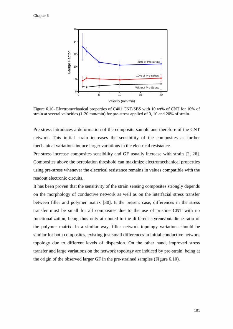
Chapter 6
101
0 5 10 15 206
8
10
12
14
16
20% of Pre-stress
10% of Pre-stress
Velocity (mm/min)
Gauge F
acto
r
Without Pre-Stress
Figure 6.10- Electromechanical properties of C401 CNT/SBS with 10 wt% of CNT for 10% of
strain at several velocities (1-20 mm/min) for pre-stress applied of 0, 10 and 20% of strain.
Pre-stress introduces a deformation of the composite sample and therefore of the CNT
network. This initial strain increases the sensibility of the composites as further
mechanical variations induce larger variations in the electrical resistance.
Pre-stress increase composites sensibility and GF usually increase with strain [2, 26].
Composites above the percolation threshold can maximize electromechanical properties
using pre-stress whenever the electrical resistance remains in values compatible with the
readout electronic circuits.
It has been proven that the sensitivity of the strain sensing composites strongly depends
on the morphology of conductive network as well as on the interfacial stress transfer
between filler and polymer matrix [30]. It the present case, differences in the stress
transfer must be small for all composites due to the use of pristine CNT with no
functionalization, being thus only attributed to the different styrene/butadiene ratio of
the polymer matrix. In a similar way, filler network topology variations should be
similar for both composites, existing just small differences in initial conductive network
topology due to different levels of dispersion. On the other hand, improved stress
transfer and large variations on the network topology are induced by pre-strain, being at
the origin of the observed larger GF in the pre-strained samples (Figure 6.10).

Upscale processing for thermoplastic elastomers styrene-butadiene-styrene/carbon nanotubes composites
for strain sensor applications
102
6.2 Conclusions
Composites of SBS with CNT fillers are prepared using up-scalable, extrusion and
electrospinning methods. SBS matrices with different butadiene/styrene ratios and
amounts of CNT are mixed and extruded having electromechanical properties that can
be used as sensor for larger strains, with a high gauge factor. Intrinsic mechanical
properties of SBS almost remain unaltered by adding CNT. Large styrene contents
increase the initial modulus for SBS matrix and it increases further with increasing CNT
content. Electrical conductivity also increases with CNT content in the composites.
Extruded composites with C540 matrix show lower electrical percolation thresholds
(less than 6 wt% CNT) and larger maximum electrical conductivity when compared to
the softer matrix. Percolation threshold of electrospun composites is lower than for
extruded composites, but larger electrical conductivities have to be reached before the
membranes can be used for electromechanical sensor applications. Composites with
SBS soft matrix show larger sensibility with maximum GF ~30 for C401 CNT/SBS
with 8 wt% CNT. Increasing the amount of CNT in the composites decreases the GF for
both matrices. CNT/SBS prepared after conventional extrusion methods can therefore
be used as sensor for larger strains up to 20% of deformation. Using pre-stress further
improves the sensitivity of the composites.

Chapter 6
103
References
[1] Rubinger C P L, Leyva M E, Soares B G, Ribeiro G M and Rubinger R M 2012
Hopping conduction on carbon black/styrene–butadiene–styrene composites J
Mater Sci 47 860-5
[2] Costa P, Silva J, Sencadas V, Simoes R, Viana J C and Lanceros-Méndez S
2013 Mechanical, electrical and electro-mechanical properties of thermoplastic
elastomer styrene-butadiene-styrene/multiwall carbon nanotubes composites J
Mater Sci 48 1172-9
[3] Tang W, Liu B, Liu Z, Tang J and Yuan H 2012 Processing-dependent high
impact polystyrene/styrene-butadiene-styrene tri-block copolymer/carbon black
antistatic composites Journal of Applied Polymer Science 123 1032-9
[4] Tsuchiya K, Sakai A, Nagaoka T, Uchida K, Furukawa T and Yajima H 2011
High electrical performance of carbon nanotubes/rubber composites with low
percolation threshold prepared with a rotation–revolution mixing technique
Composites Science and Technology 71 1098-104
[5] Huang Z-M, Zhang Y Z, Kotaki M and Ramakrishna S 2003 A review on
polymer nanofibers by electrospinning and their applications in nanocomposites
Composites Science and Technology 63 2223-53
[6] Norris I D, Shaker M M, Ko F K and MacDiarmid A G 2000 Electrostatic
fabrication of ultrafine conducting fibers: polyaniline/polyethylene oxide blends
Synthetic Metals 114 109-14
[7] Senecal K J, Ziegler D P, He J, Mosurkal R, Schreuder-Gibson H and
Samuelson L A 2001 Photoelectric Response from Nanofibous Membranes MRS
Online Proceedings Library 708 null-null
[8] Lorenz H, Fritzsche J, Das A, Stöckelhuber K W, Jurk R, Heinrich G and
Klüppel M 2009 Advanced elastomer nano-composites based on CNT-hybrid
filler systems Composites Science and Technology 69 2135-43
[9] Breuer O and Sundararaj U 2004 Big returns from small fibers: A review of
polymer/carbon nanotube composites Polymer Composites 25 630-45
[10] Al-Saleh M H and Sundararaj U 2009 A review of vapor grown carbon
nanofiber/polymer conductive composites Carbon 47 2-22
[11] Mao Z, Wu W, Xie C, Zhang D and Jiang X 2011 Lipophilic carbon nanotubes
and their phase-separation in SBS Polymer Testing 30 260-70
[12] Theodosiou T C and Saravanos D A 2010 Numerical investigation of
mechanisms affecting the piezoresistive properties of CNT-doped polymers
using multi-scale models Composites Science and Technology 70 1312-20
[13] Shih R-S, Kuo S-W and Chang F-C 2011 Thermal and mechanical properties of
microcellular thermoplastic SBS/PS/SBR blend: effect of crosslinking Polymer
52 752-9
[14] Munteanu S B, Brebu M and Vasile C 2005 Thermal and thermo-oxidative
behaviour of butadiene-styrene copolymers with different architectures Polymer
Degradation and Stability 89 501-12
[15] Canto L B, Mantovani G L, deAzevedo E R, Bonagamba T J, Hage E and
Pessan L A 2006 Molecular Characterization of Styrene-Butadiene-Styrene
Block Copolymers (SBS) by GPC, NMR, and FTIR Polym. Bull. 57 513-24
[16] De Falco A, Goyanes S, Rubiolo G H, Mondragon I and Marzocca A 2007
Carbon nanotubes as reinforcement of styrene–butadiene rubber Applied Surface
Science 254 262-5
[17] Das A, Stöckelhuber K W, Jurk R, Saphiannikova M, Fritzsche J, Lorenz H,
Klüppel M and Heinrich G 2008 Modified and unmodified multiwalled carbon

Upscale processing for thermoplastic elastomers styrene-butadiene-styrene/carbon nanotubes composites
for strain sensor applications
104
nanotubes in high performance solution-styrene–butadiene and butadiene rubber
blends Polymer 49 5276-83
[18] Pedroni L G, Soto-Oviedo M A, Rosolen J M, Felisberti M I and Nogueira A F
2009 Conductivity and mechanical properties of composites based on MWCNTs
and styrene-butadiene-styrene block™ copolymers Journal of Applied Polymer
Science 112 3241-8
[19] Villmow T, Kretzschmar B and Pötschke P 2010 Influence of screw
configuration, residence time, and specific mechanical energy in twin-screw
extrusion of polycaprolactone/multi-walled carbon nanotube composites
Composites Science and Technology 70 2045-55
[20] Spitalsky Z, Tasis D, Papagelis K and Galiotis C 2010 Carbon nanotube–
polymer composites: Chemistry, processing, mechanical and electrical
properties Progress in Polymer Science 35 357-401
[21] Sandler J K W, Kirk J E, Kinloch I A, Shaffer M S P and Windle A H 2003
Ultra-low electrical percolation threshold in carbon-nanotube-epoxy composites
Polymer 44 5893-9
[22] Bilotti E, Zhang H, Deng H, Zhang R, Fu Q and Peijs T 2013 Controlling the
dynamic percolation of carbon nanotube based conductive polymer composites
by addition of secondary nanofillers: The effect on electrical conductivity and
tuneable sensing behaviour Composites Science and Technology 74 85-90
[23] Hapuarachchi T D, Bilotti E, Reynolds C T and Peijs T 2011 The synergistic
performance of multiwalled carbon nanotubes and sepiolite nanoclays as flame
retardants for unsaturated polyester Fire and Materials 35 157-69
[24] Peeterbroeck S, Alexandre M, Nagy J B, Pirlot C, Fonseca A, Moreau N,
Philippin G, Delhalle J, Mekhalif Z, Sporken R, Beyer G and Dubois P 2004
Polymer-layered silicate–carbon nanotube nanocomposites: unique nanofiller
synergistic effect Composites Science and Technology 64 2317-23
[25] Costa P, Ferreira A, Sencadas V, Viana J C and Lanceros-Méndez S 2013
Electro-mechanical properties of triblock copolymer styrene-butadiene-styrene /
carbon nanotube composites for large deformation sensor applications
Conposites B: Engeineering, submitted
[26] Slobodian P, Riha P and Saha P 2012 A highly-deformable composite composed
of an entangled network of electrically-conductive carbon-nanotubes embedded
in elastic polyurethane Carbon 50 3446-53
[27] Shanks R A and Spoljaric S 2012 Novel elastomer dye-functionalised POSS
nanocomposites: Enhanced colourimetric, thermomechanical and thermal
properties eXPRESS Polymer Letters 6 354-72
[28] Wu J-H, Li C-H, Wu Y-T, Leu M-T and Tsai Y 2010 Thermal resistance and
dynamic damping properties of poly (styrene–butadiene–styrene)/thermoplastic
polyurethane composites elastomer material Composites Science and
Technology 70 1258-64
[29] Chen Q, Liang S and Thouas G A 2013 Elastomeric biomaterials for tissue
engineering Progress in Polymer Science 38 584-671
[30] Hu N, Karube Y, Yan C, Masuda Z and Fukunaga H 2008 Tunneling effect in a
polymer/carbon nanotube nanocomposite strain sensor Acta Materialia 56 2929-
36
[31] Wichmann M H G, Buschhorn S T, Gehrmann J and Schulte K 2009
Piezoresistive response of epoxy composites with carbon nanoparticles under
tensile load Physical Review B 80 245437

Chapter 7
105
Chapter 7. Implementation of styrene-butadiene-styrene/carbon
nanotube composites as fingers movement sensor in a hand glove
Styrene-butadiene-styrene/carbon nanotube composites can be processed by different
methods and can be used as deformation sensors. They can be incorporated into
sportswear or equipment to measure, for example, movements of knees, elbows and
fingers as well as deformations or impacts in sports equipment.
Electronic readout electronics and wireless communication have been implemented.

Implementation of styrene-butadiene-styrene/carbon nanotube composites as fingers movement sensor in
a hand glove
106
7.1 Hand glove application
The extruded wire composites are ideal materials to measure large deformations.
Extruded composites can measure electromechanical properties until 30% of
deformation, or more (chapter 6), when CNT content is above of percolation threshold.
Four wires of C540 CNT/SBS with 8 wt% CNT filler content were placed on a hand
glove in order to measure finger deflection.
For integration as a part of the electromechanical sensor system for a smart glove, in
order to allow measurement of the deformation and the movement of the different
fingers, it is necessary to develop a readout system appropriate for this specific
application.
The sensor interface should be highly configurable to allow the control system to adjust
the condition circuit to the sensor to read. This is important as, although all
electromechanical sensors show variation of their resistance when subjected to a
deformation, the initial resistance of the various sensors is not the same and therefore
the resistance variation is not identical either.
To meet these requirements the circuit structure shown in figure 7.1 was developed.
This microsystem uses a total open architecture being a key feature of this circuit the
use of a single readout circuit for all sensors, which enables a substantial reduction in
implementation area.
Figure 7.1- Block diagram of the piezoresistive multi-sensor interface circuit.

Chapter 7
107
The various sensors are connected to a multiplexer circuit that allows addressing each
sensor independently, thus ensuring that the rest are in open circuit and ensuring that
they do not affect a given measurement and that there is unnecessary power
consumption.
A multiplexing circuit for just eight channels has been developed, but is easily
converted to a large number of channels as the readout circuit is completely independent
of the number of input channels.
So one end of the sensor is connected to a controlled current source, and the other end
connected to programmable gain application circuit. In this way, the source injects a
constant current through the sensor, which by varying the sensor resistance causes a
voltage change at the entrance of the amplifier. After signal amplification, this is
measured thought an analogic digital converter incorporated internally in the
microcontroller (MC).
This microcontroller is also responsible for making the activation of the measuring
sensors as well as for the control of current and amplification gain for each channel. The
microcontroller unit (MCU) communication with the various blocks of the readout
circuit is performed using a serial peripheral interface bus which allows to control all
circuit devices quickly and with a minimum of connections.
The measured data are sent via radio frequency (RF) to a remote platform responsible
for data recording, allowing deformation measuring of the various sensors in real time
and without requiring a physical connection.
In this way, the monitoring platform shown in figure 7.2 was implemented on a
computer, which is connected to the RF receiver module with a universal serial bus
connection.

Implementation of styrene-butadiene-styrene/carbon nanotube composites as fingers movement sensor in
a hand glove
108
Figure 7.2- Monitoring platform for real time sensor data adquisition.
The development platform allows visualizing the response of the various sensors in real
time and performs the recording of the entire measurement period to a file for a later
detailed analysis.
It is important to note that the developed architecture was implemented using
commercial electronic components which enable a quick transition from the architecture
to the functional prototype and thus able to evaluate how the developed system meets
the requirements.
The experimental procedure started by stitching the wires in the hand glove as sown in
figure 7.3.
Figure 7.3- Images of the glove with the extruded composite C540 CNT/SBS with 8 wt% CNT
filler content for measuring finger deformation via wireless data transmission.
After connection of the wires to the electronic platform, figure movement were
monitored both by single and simultaneous finger movement experiments.

Chapter 7
109
As electromechanical tests in chapter 6 suggest, the electrical resistance increase when
the CNT/SBS composites wirer are stretched. Figure 7.4 shows that the voltage
variation of the composites (at constant current) increases linearly (and therefore the
resistance) when the wire is stretched.
0 20 40 60 80 100
2.6
2.8
3.0
3.2
3.4
3.6
3.8
4.0
4.2
All fingers flection
Vo
lta
ge
(V
)
Time (s)
Sensor 1
Sensor 2
Sensor 3
Sensor 4
Individual finger flectionA
0 10 20 30 40 502.8
3.0
3.2
3.4
3.6
3.8
4.0
4.2
Sensor 1
Sensor 2
Sensor 3
Sensor 4
Voltage (
V)
Time (s)
All fingers in movement at same time
B
Figure 7.4- Data points of 4 sensors (extruded composites C540 CNT/SBS with 8 wt% CNT)
stitched on the hand glove (figure 7.3). A) individual and all finger movement and B) all fingers
in movement at the same time.
Figure 7.4 (A and B) shows that the voltage variation during the deflection of the
fingers, either individual finger movements or simultaneous movements can be properly
recorded.
This proof of concept shows that composite materials can be used as large deformation
sensors in sportswear or equipments. With the developed electronic data acquisition is it
possible to visualize in real time and to analyze the sensor measurements.

110

Chapter 8
111
Chapter 8. Conclusions and future work

Conclusions and future work
112
8.1 Conclusions
The main objective of this investigation was to prepare elastomeric composites suitable
for the development of large strain deformation sensors. Further, it was intended to
understand the main parameters affecting composite performance and characteristic,
such as dispersion, mechanical, electrical, thermal and electromechanical properties.
In this way, elastomeric composites have been successfully prepared and understood
with suitable and tailored properties for applications as strain sensors.
Different styrene-butadiene-styrene matrices, C401, C411, C500 and C540 with ratio
butadiene/styrene of 80/20 to 60/40 and linear or radial structure show interesting
electromechanical properties for specific CNT contents, depending on the processing
method.
A proof of concept of the suitability of the prepared materials for applications has been
achieved by using extruded composites for the development of a hand glove with the
ability to measure fingers movements.
With respect to the main characteristics and specific conclusion of the developed
composites:
Thermal properties of SBS show two different Tg ascribed to polybutadiene and
polystyrene domains. The polybutadiene glass transition increases with increasing
butadiene in SBS matrix, from 10 to 17 ºC, with the polystyrene glass transition
around 70-75 ºC. Thermal degradation of composites shows Tonset around 450-455
ºC and Tmax between 490 and 520 ºC, increasing with amount of CNT in SBS
matrices. All others thermal properties of composites CNT/SBS remain similar to
SBS matrix.
The peaks at the wave-number of 966 cm-1
and 699 cm-1
were selected as the most
suitable ones for analysis of polybutadiene (PB) and polystyrene (PS), respectively.
The butadiene/styrene ratio and structure (linear or radial) does not affect the
characteristic peaks in SBS composites as well as the filler type and content did not
induce any change in the SBS matrices. No new bonds attributable to CNT-matrix
interactions are identified.
Different processing methods exhibit some advantages and limitations. Mechanical
properties of composites, in general, increase with increasing CNT content in the
SBS matrix for all methods. Maximum deformation is larger for extruded
composites (between 800 to 3500%) and electrospun composites present the

Chapter 8
113
smallest maximum deformations (less than 600%). Initial modulus increases with
increasing CNT and styrene content in SBS matrices, for the different processing
methods. The Yield stress decreases with increasing styrene content in the SBS
matrix and is the largest in extruded composites, being for the softer matrix (C401)
between 20% and 50%. These values are around 10 times higher than for other
processed composites, solvent casted and electrospun. Mechanical hysteresis is an
important issue for large deformation electromechanical sensors. CNT/SBS
composites properly recovery from large deformations and mechanical hysteresis
increases with deformation and decreases with the number of stress-strain cycles.
Butadiene/styrene ratio influences the mechanical behavior and softer matrices
(C401) show lower hysteresis than harder matrices (C540).
Electrical properties of CNT/SBS depend on the processing method: whereas the
electrical percolation threshold is less than 1 wt% for solvent casting and
electrospinning methods, increases for 4-5 wt% in extruded composites.
Functionalized CNT does not show a strong increase of the electrical conductivity
of the matrix until 8 wt% CNT loading. These can be explained with CNT
dispersion inside SBS matrix, as functionalized CNTs show CNT dispersion and
pristine CNTs show clusters of CNT dispersion. Individual CNT dispersion does not
favor electrical conductivity in carbon nanoallotropes/polymer composites. Different
CNT present similar electrical properties in composites, but NC7000 CNTs shows
lower percolation thresholds and higher conductivity.
Percolation theory predicts that hopping between nearest fillers is the main
mechanism for the composite electrical conduction; the overall composite
conductivity is explained by the existence of a weak disorder regime.
The CNT/SBS composites show electromechanical properties in the four different
matrices with appropriate CNT contents, which must be larger than the percolation
threshold for the different composites and for large deformation applications. For
solvent casting method the C540 SBS present higher GF up to 20% of deformation.
This composite can reach a GF~120 using pre-stress in uniaxial stress-strain
measurements. For uniaxial electromechanical measurements the speed of the
mechanical stimulus influences the GF and is larger for deformations speeds
between 10-20 mm/min, decreasing for larger speeds. The good linearity between
mechanical and electrical resistance variation is also observed in 4-point-bending
measurements with GF~100 for C401 CNT/SBS composites at 5 mm/min and 1 mm

Conclusions and future work
114
of deformation. Others matrices, C411, C500 and C540, show GF<30. For uniaxial
stress-strain solicitations, C150P CNT show higher GF for larger deformations, but
multi walled CNT NC7000 and single walled CNT AP-SWNT shows GF between 3
and 5, which are also suitable for applications.
Composites near the percolation threshold show higher GF than composites above
the percolation threshold, but the maximum deformation is smaller for these
composites, increasing with increasing filler content in the composites.
Extruded composites under uniaxial stress-strain measurements show maximum GF
for the softer matrix with 8 wt% CNT, reaching a GF~30 for 20% deformation.
Electrospun samples results in composites with similar electrical properties as
solvent casted samples and maximum deformations larger than 250%.
The applicability of the materials has been shown by the development of an
instrumented glove for measuring finger deformations.
8.2 Future work
The CNT/SBS composites can be used as electromechanical sensors. Several
parameters can be optimized for preparing the materials for specific applications,
including CNT content, initial pre-stress, butadiene/styrene ratio, among others.
The variability of processing methods also allows a large application range and
industrial fabrication.
In this way, the main challenge for the future is to optimize materials already for
specific applications, introducing the materials into specific devices and optimizing the
upscaled production.
In this way, electrospun and extruded composites can be incorporated at different scales
and, for example, cloths can be produced with these sensors already incorporated with
the objectives of monitoring movement. Intelligent hand gloves are another example of
the use of these electromechanical composites. Apart from the clothes, these composites
can be incorporated into sport equipments.
The SBS matrices can be studied as pressure sensors. Silicone or natural rubbers are
softer than SBS but present lower recovery to initial state after the applied pressure is
released.

Chapter 8
115
The exceptional mechanical properties of SBS make these thermoplastic elastomer
excellent matrices to renewable energy sources and their properties should be explored
in this field. Dielectric elastomer generators (DEG) are being developed based on the
change of the capacitance of a deformable dielectric and energy is harvested through a
cycle. Energy of conversion is higher for larger strains.
Top Related