


Languages
Pages
Legal


DEFCON 18
Electronic WeaponsPresented by: mage2

Warning
Mucking about with the things I am about to talk to you about can and will
kill you and all puppies, kittens and laptops around you. So be forewarned. Also transmitting on frequencies you are not licensed for can really piss off the FCC and DHS, depending on what
trouble you cause.

Warning Part 2
This is a warning to all of those in the room right now. I am a horrid public speaker, I
tend to talk fast and can easily get off topic.
Now you are thinking why is he up there talking...Well I wanted to bring something to DEFCON, this is my 10th year attending. Things like this is something I am interested in and I want to bring my interests
to others. I want to make you ask questions. If you have a question I hope to have a good
amount of time after the slides for Q/A, I will also be around after the talk.

What we will cover
EMPEFI/RFILasers
Others, etc

Electronic Basic Concepts
* All conductive material can act as an antenna.* Most electronics are sensitive to voltage spikes.* Most communication based electronics run on relatively low power signals. < 1W* Atomic and Nuclear weapons are not the only sources of EMP.* Voltage is based on the potential difference between the source and the ground.* Ohms law , learn it love it. V over IR squared. * We all know computers and all digital electronics run on binary signals.* This is represented as a square wave between 0v/GND and either 3.3v or 5v* There is a threshold of what the hardware expects to see as a high or a low.* When using transformers , you will trade current for voltage.* RF power diminishes over distance, closer = better.

What are we working with

RFI/EMI
Using RFI/EMI as an attack is usually a DOS type of an attack. You will be creating a signal that is stronger than your target's signal. Your
signal can be anything or just noise. These can be one of the easiest tools to aquire/build.

RFI/EMI cont.
Here are a few of the devices that can be used for this type of attack.●Spark Gap transmitter. ●Other “off the shelf” transmitters.●Homebrew transmitters.

Spark Gap Transmitter
●The spark gap transmitter was the first device used to transmit data over the air.●It is a wide band transmitter.●Simple to build. With components easily sourced.●Easily designed to output high powers.●Dangerous at any power level.●Electrical arc's produce UV light, exposure can cause “sunburn” and damage your eyes.

Spark Gap Transmitter
This is a simple spark gap transmitter design.
It uses few parts, the components will need to be rated for the voltage levels.

Off the shelf transmitters
I thought about listing sources of transmitters sold off the shelf that could be used as “jammers” but decided not to out anyone.
Any HAM radio can be used,There are plenty of places on the net where you can purchase “jammers”.
All of this violates FCC regulations and can cause you legal problems.
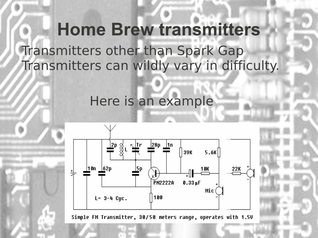
Home Brew transmitters
Here is an example
Transmitters other than Spark Gap Transmitters can wildly vary in difficulty.

EMP
An EMP is a electromagnetic wave with enough power that it can create over-voltage situations in wires and traces on circuit boards. This is because the
magnetic field from the EMP induces a voltage on the wires/traces this can be
100s or even thousands of volts.

What can make a EMP?Creating Long range EMP is a difficult task. All require either the power grid of a small city or involve explosives.
Any atomic or nuclear weapon will create an EMP.
EMP was first predicted by a guy named Enrico Fermi during the first nuclear test in 1945.
There are reports of a non-nuclear EMP weapon in testing/use by the US military during the Iraq wars.
One type of non-nuclear EMP weapons is called “explosively pumped flux compression generator”.
Another option is to use a large low-inductance capacitor bank discharged into a single loop antenna.

Why do we care?
RFI/EMI could be utilized to disable anything from GPS to radio
communications. Even low power EMP could disable a city block to a city and could damage the infrastructure we all
depend on.
How would you feel without your latest and greatest smartphone or
other tech you rely on?

Protection from RFI
There are a few ways to protect yourself/your signal from RFI.
●Using spread spectrum/frequency hopping would make “jamming” your signal much harder.
●For data the better your error correction the better your chances of pulling your signal out of the noise.
●Good shielding of the RF components in the transmitter would also help.

Protection from EMP
Shielding in the form of Faraday cages, and using well shielded and grounded
chassis.Distance from whatever is creating the
EMP is your safest bet.

Projectile Based
There are a few devices of electronic origin that fire projectiles as a firearm
does.
These are: Coil/Gauss gun
Rail gun

Coil/Gauss and Rail guns
The coil/gauss gun fire using a energized wire coil as a electromagnet to pull the projectile down the barrel. The projectile must be ferrous (magnetic). The more advanced gauss guns use many stages of coils fired in sequence to accelerate the projectile.
Rail guns use magnetic fields to push a projectile down the rails. They are very power hungry.
All of these devices are power hungry. They require specialized design and components

LasersWeaponized lasers are coming of age. There are more
military platforms using lasers for defense than an other non traditional weapons.
I think everyone here knows how lasers work, so this is just to point out what we have made public.
The most powerful military laser that has been made public is the MIRACL laser that is currently based out of White Sands missile range in New Mexico. (anyone up for a road trip?)
Just looking around I found about a dozen different projects using “directed energy” weapons for both
offensive and defensive roles.

For you that have survived thus far.
Now as you have all noticed, electronic weapons are all power hungry
bastards. How does one feed them?

The parts that make them
Here are the parts that you will want to understand. And this will help
clarify the schematics you will see next

Resistors
Resistors resist the flow of energy and convert the waste energy into heat. They are used to limit the current or voltage in a circuit. The are rated in
Ohms or Ω.Here is the electronic symbol

Coils
Coils are are also called inductors, they work by storing energy in the
form of a magnetic field.They are rated in henries. Usually mH.These are pretty easy to make for the
home experimenter Here is the electronic symbol

Capacitors
Capacitors store energy between two conductive plates separated by a
dielectric material. They are measured in Farads, and come in a few flavors.
These are also somewhat easy to make at home even for high voltages.
Here is the electronic symbol

Diode
Diodes allow current to flow in only one direction. They also come in many flavors. They are used most often to
rectify an A/C voltage and create a DC voltage.
Here is one of the the electronic symbols

Transistors
Transistors are at the most basic electronic switches. They are used in
amplifiers of all kinds.Here is one of the the electronic
symbols
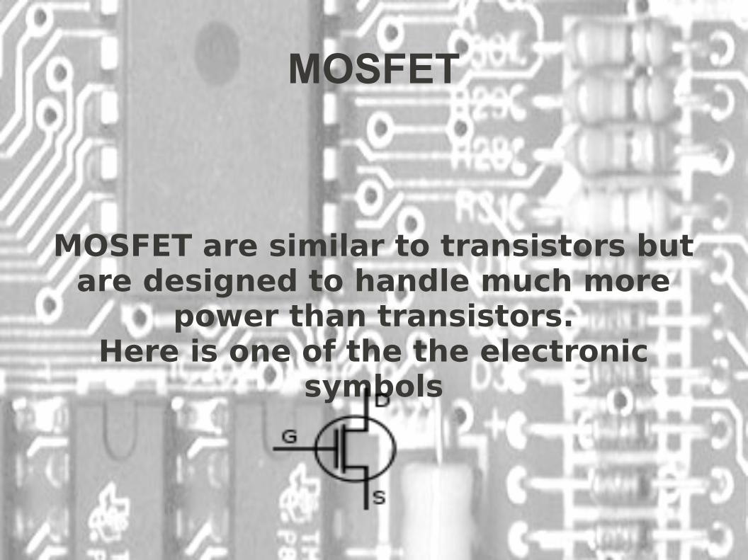
MOSFET
MOSFET are similar to transistors but are designed to handle much more
power than transistors.Here is one of the the electronic
symbols

HV TransformersAll transformers are based on the same
principle. You feed one side of a pair of coils a A/C voltage, it creates a alternating
magnetic field thus inducing a voltage in its partner coil. The increase in voltage is based
on the number of turns in the coil. For instance a 1:1000 would increase 10V A/C to
10000V A/C
The most common transformers we are interested in are neon sign transformers, fly
back transformers, ignition coils, and microwave oven transformers. They each
have a ratio of at least 1:200.

There are many more parts
There is no way I could cover all the possible components .

Power Supplies
The next part we are going to cover some of the common power supplies
used with these devices.

Marx GeneratorA Marx Generator is use to change a low voltage source to a high voltage pulse. The construction is
caps that are charged in parallel to a given
voltage. Once charged the caps are
discharged in series multiplying the V * N the number of caps.example: 10 caps @ 120 v would be 1200
V output.

Voltage MultipliersThis power supply is similar to a Marx
GeneratorThis converts a lower AC voltage to a
high DC voltage.

Humans as Targets
The last part of this talk is about the new wave of using our tech on us. These are some of the newer “less than lethal” weapons that are just starting to be used on the public.

Less than lethal?
The term “non lethal” was initially used on things like stun
guns,beanbag,tear gas, and CS based weapons. That is until they started
having fatalities.

“Heat Rays”These use high frequency microwaves to
produce a heat/burning sensation on exposed skin. It is deemed safe because the waves do not penetrate far into the skin. It
is currently truck mounted but there is work on a more mobile option. This is named the
ADC (Active Denial System)

Sea Sickness Flashlight AKA Dazzler
This uses a extremely bright light with a random flashing pattern. It was
created to cause nausea and disorientation or temp blindness. I think it could also possibly cause
seizure in those that are predisposed to that.
It was created by a DOD contractor and was recreated by Lady Ada.

Sonic Cannon(LRAD)These devices are designed for crowd control,
they utilize sound at high db levels (160db), they seem to mostly use either very high or very low frequencies. Low frequencies at high levels are
known to cause nausea and vision problems. High frequency will cause headaches and loss of focus.
Not to mention your ear drums.150db is the point where most people feel pain.
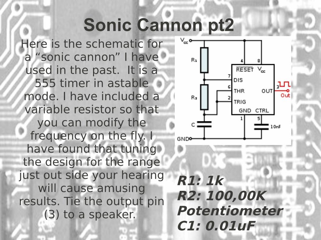
Sonic Cannon pt2Here is the schematic for a “sonic cannon” I have used in the past. It is a
555 timer in astable mode. I have included a variable resistor so that
you can modify the frequency on the fly. I
have found that tuning the design for the range
just out side your hearing will cause amusing
results. Tie the output pin (3) to a speaker.
R1: 1kR2: 100,00K Potentiometer C1: 0.01uF

Sound Cannon BuildI have made a home brew version of the sound
cannon.List of parts:
IC1: 555 timerR1: 100k variable resistor
R2: 470 ohm resistorC1: 0.01 uF cap
C2: 1000 uF capC3: 0.001 uF cap
SpeakersBreadboardMisc wire.
Power

Sound Cannon build PT 2 Tips
I would suggest first prototyping the circuit on a solderless breadboard to get it working as you
want. When working on the final build make sure to use a IC socket.

Sound Cannon Build
Build the circuit as shown in schematic. C2 is a DC filtering cap that should be put between the output wire and ground. . The resistor values I used should give you a good range of output
frequencies in the mostly audible range.

Sonic Cannon Done
Now you have one hell of a noise maker.

Thanks
My thanks go to those that helped with this.
WikipediaRandall with XKCD
Lady Adafruit

Questions and Answers
Here is where you ask me questions and I make up some answers.
Top Related