


Languages
Pages
Legal

https://edocs.imo.org/Final Documents/English/MEPC.1-CIRC.855-REV.1 (E).doc
E
4 ALBERT EMBANKMENT
LONDON SE1 7SR Telephone: +44 (0)20 7735 7611 Fax: +44 (0)20 7587 3210
MEPC.1/Circ.855/Rev.1
8 October 2015
2014 GUIDELINES ON SURVEY AND CERTIFICATION OF
THE ENERGY EFFICIENCY DESIGN INDEX (EEDI), AS AMENDED (RESOLUTION MEPC.254(67), AS AMENDED BY RESOLUTION MEPC.261(68))
1 The Marine Environment Protection Committee, at its sixty-eighth session (11 to 15 May 2015), adopted, by resolution MEPC.261(68), amendments to the 2014 Guidelines on survey and certification of the Energy Efficiency Design Index (EEDI) (resolution MEPC.254(67)). A consolidated text of the guidelines, as requested by the Committee (MEPC 68/21, paragraph 3.99), is set out in the annex. 2 The Committee also endorsed the use of ISO standard 15016:2015 for ships for which the sea trial is conducted on or after 1 September 2015 and encouraged the application of the standard prior to that date (MEPC 68/21, paragraph 3.100). 3 Member Governments are invited to bring the annexed 2014 Guidelines on survey and certification of the Energy Efficiency Design Index (EEDI), as amended, to the attention of Administrations, industry, relevant shipping organizations, shipping companies and other stakeholders concerned. 4 The 2014 Guidelines revoke the 2012 Guidelines on survey and certification of the Energy Efficiency Design Index (EEDI) (resolution MEPC.214(63), as amended by resolution MEPC.234(65)). Consequently, this circular revokes MEPC.1/Circ.816.
***

MEPC.1/Circ.855/Rev.1 Annex, page 1
https://edocs.imo.org/Final Documents/English/MEPC.1-CIRC.855-REV.1 (E).doc
ANNEX
2014 GUIDELINES ON SURVEY AND CERTIFICATION OF THE ENERGY EFFICIENCY DESIGN INDEX (EEDI), AS AMENDED
(RESOLUTION MEPC.254 (67), AS AMENDED BY RESOLUTION MEPC.261 (68))
Table of contents 1 GENERAL 2 DEFINITIONS 3 APPLICATION 4 PROCEDURES FOR SURVEY AND CERTIFICATION
4.1 General
4.2 Preliminary verification of the attained EEDI at the design stage
4.3 Final verification of the attained EEDI at sea trial
4.4 Verification of the attained EEDI in case of major conversion Appendix 1 Sample of EEDI Technical File Appendix 2 Guidelines for validation of electric power tables for EEDI (EPT-EEDI) Appendix 3 Electric power table form for EEDI (EPT-EEDI Form) and statement
of validation
MEPC.1/Circ.855/Rev.1 Annex, page 2
https://edocs.imo.org/Final Documents/English/MEPC.1-CIRC.855-REV.1 (E).doc
1 GENERAL The purpose of these guidelines is to assist verifiers of the Energy Efficiency Design Index (EEDI) of ships in conducting the survey and certification of the EEDI, in accordance with regulations 5, 6, 7, 8 and 9 of MARPOL Annex VI, and assist shipowners, shipbuilders, manufacturers and other interested parties in understanding the procedures for the survey and certification of the EEDI. 2 DEFINITIONS1 2.1 Verifier means an Administration, or organization duly authorized by it, which conducts the survey and certification of the EEDI in accordance with regulations 5, 6, 7, 8 and 9 of MARPOL Annex VI and these guidelines. 2.2 Ship of the same type means a ship the hull form (expressed in the lines such as sheer plan and body plan), excluding additional hull features such as fins, and principal particulars of which are identical to that of the base ship. 2.3 Tank test means model towing tests, model self-propulsion tests and model propeller open water tests. Numerical calculations may be accepted as equivalent to model propeller open water tests or used to complement the tank tests conducted (e.g. to evaluate the effect of additional hull features such as fins, etc. on ships' performance) with the approval of the verifier. 3 APPLICATION These guidelines should be applied to new ships for which an application for an initial survey or an additional survey specified in regulation 5 of MARPOL Annex VI has been submitted to a verifier. 4 PROCEDURES FOR SURVEY AND CERTIFICATION 4.1 General 4.1.1 The attained EEDI should be calculated in accordance with regulation 20 of MARPOL Annex VI and the 2014 Guidelines on the method of calculation of the attained Energy Efficiency Design Index (EEDI) for new ships, as amended (resolution MEPC.245(66), as amended by resolution MEPC.263(68)) (EEDI Calculation Guidelines). Survey and certification of the EEDI should be conducted in two stages: preliminary verification at the design stage and final verification at the sea trial. The basic flow of the survey and certification process is presented in figure 1. 4.1.2 The information used in the verification process may contain confidential information of submitters which requires Intellectual Property Rights (IPR) protection. In the case where the submitter wants a non-disclosure agreement with the verifier, the additional information should be provided to the verifier upon mutually agreed terms and conditions.
1 Other terms used in these guidelines have the same meaning as those defined in the 2014 Guidelines on
the method of calculation of the attained EEDI for new ships, as amended (resolution MEPC.245(66), as amended by resolution MEPC.263(68)).

MEPC.1/Circ.855/Rev.1 Annex, page 3
https://edocs.imo.org/Final Documents/English/MEPC.1-CIRC.855-REV.1 (E).doc
* To be conducted by a test organization or a submitter.
Figure 1: Basic flow of survey and certification process
4.2 Preliminary verification of the attained EEDI at the design stage 4.2.1 For the preliminary verification at the design stage, an application for an initial survey and an EEDI Technical File containing the necessary information for the verification and other relevant background documents should be submitted to a verifier. 4.2.2 The EEDI Technical File should be written at least in English. The EEDI Technical File should include as a minimum, but not limited to:
.1 deadweight (DWT) or gross tonnage (GT) for passenger and ro-ro passenger ships, the maximum continuous rating (MCR) of the main and auxiliary engines, the ship speed (Vref), as specified in paragraph 2.2 of the EEDI Calculation Guidelines, type of fuel, the specific fuel consumption (SFC) of the main engine at 75% of MCR power, the SFC of the auxiliary engines at 50% MCR power, and the electric power table2 for certain ship types, as necessary, as defined in the EEDI Calculation Guidelines;
2 Electric power tables should be validated separately, taking into account the guidelines set out in
appendix 2.
Submitter Verifier
Basic design, Tank test*,
EEDI calculation
Development of EEDI Technical File
Verification:
- EEDI Technical File
- Additional information Submission of additional
information Issuance of
report of pre-verification
Verification:
- Sea trial condition
- Ship speed
- Revised EEDI Technical File
Sea trial
Modification and resubmission of EEDI Technical File
Issuance of certificate
Start of ship construction
Delivery of ship
Witness model Tank test
MEPC.1/Circ.855/Rev.1 Annex, page 4
https://edocs.imo.org/Final Documents/English/MEPC.1-CIRC.855-REV.1 (E).doc
.2 power curve(s) (kW – knot) estimated at design stage under the condition as specified in paragraph 2.2 of the EEDI Calculation Guidelines, and, in the event that the sea trial is carried out in a condition other than the above condition, also a power curve estimated under the sea trial condition;
.3 principal particulars, ship type and the relevant information to classify the
ship as such a ship type, classification notations and an overview of the propulsion system and electricity supply system on board;
.4 estimation process and methodology of the power curves at design stage;
.5 description of energy saving equipment;
.6 calculated value of the attained EEDI, including the calculation summary, which should contain, at a minimum, each value of the calculation parameters and the calculation process used to determine the attained EEDI;
.7 calculated values of the attained EEDIweather and fw value (not equal to 1.0), if those values are calculated, based on the EEDI Calculation Guidelines; and
.8 for LNG carriers:
.1 type and outline of propulsion systems (such as direct drive diesel, diesel electric, steam turbine);
.2 LNG cargo tank capacity in m3 and BOR as defined in
paragraph 2.5.6.3 of the EEDI Calculation Guidelines; .3 shaft power of the propeller shaft after transmission gear at 100%
of the rated output of motor (MPPMotor) and (i) for diesel electric;
.4 maximum continuous rated power (MCRSteamTurbine) for steam turbine; and
.5 SFCSteamTurbine for steam turbine, as specified in paragraph 2.5.7 of
the EEDI Calculation Guidelines.
A sample of an EEDI Technical File is provided in appendix 1.
4.2.3 For ships equipped with dual-fuel engine(s) using LNG and fuel oil, the CF-factor for gas (LNG) and the specific fuel consumption (SFC) of gas fuel should be used by applying the following criteria as a basis for the guidance of the Administration:
.1 final decision on the primary fuel rests with the Administration; .2 the ratio of calorific value of gas fuel (LNG) to total marine fuels
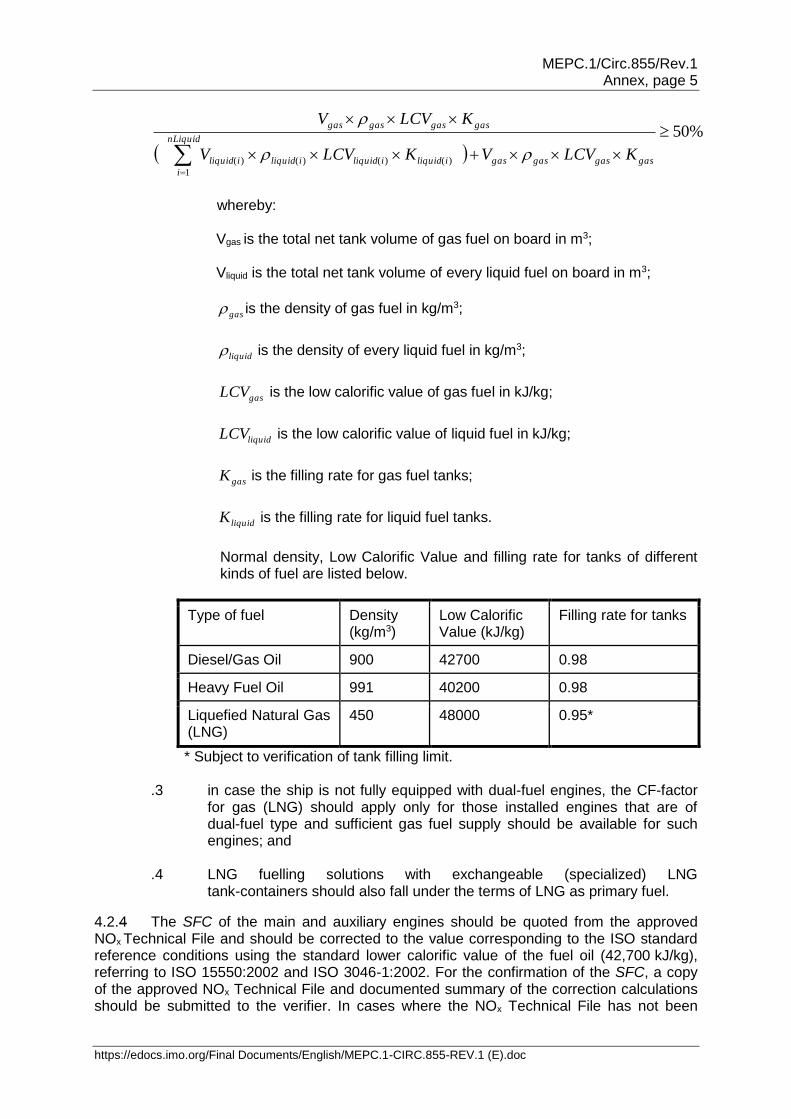
(HFO/MGO), including gas fuel (LNG) at design conditions should be equal to or larger than 50% in accordance with the formula below. However, the Administration can accept a lower value of the percentage taking into account the intended voyages:
MEPC.1/Circ.855/Rev.1 Annex, page 5
https://edocs.imo.org/Final Documents/English/MEPC.1-CIRC.855-REV.1 (E).doc
%50
)()()()(
1
gasgasgasgasiliquidiliquidiliquidiliquid
nLiquid
i
gasgasgasgas
KLCVVKLCVV
KLCVV
whereby:
Vgas is the total net tank volume of gas fuel on board in m3; Vliquid is the total net tank volume of every liquid fuel on board in m3;
gas is the density of gas fuel in kg/m3;
liquid is the density of every liquid fuel in kg/m3;
gasLCV is the low calorific value of gas fuel in kJ/kg;
liquidLCV is the low calorific value of liquid fuel in kJ/kg;
gasK is the filling rate for gas fuel tanks;
liquidK is the filling rate for liquid fuel tanks.
Normal density, Low Calorific Value and filling rate for tanks of different kinds of fuel are listed below.
Type of fuel Density (kg/m3)
Low Calorific Value (kJ/kg)
Filling rate for tanks
Diesel/Gas Oil 900 42700 0.98
Heavy Fuel Oil 991 40200 0.98
Liquefied Natural Gas (LNG)
450 48000 0.95*
* Subject to verification of tank filling limit.
.3 in case the ship is not fully equipped with dual-fuel engines, the CF-factor for gas (LNG) should apply only for those installed engines that are of dual-fuel type and sufficient gas fuel supply should be available for such engines; and
.4 LNG fuelling solutions with exchangeable (specialized) LNG
tank-containers should also fall under the terms of LNG as primary fuel.
4.2.4 The SFC of the main and auxiliary engines should be quoted from the approved NOx Technical File and should be corrected to the value corresponding to the ISO standard reference conditions using the standard lower calorific value of the fuel oil (42,700 kJ/kg), referring to ISO 15550:2002 and ISO 3046-1:2002. For the confirmation of the SFC, a copy of the approved NOx Technical File and documented summary of the correction calculations should be submitted to the verifier. In cases where the NOx Technical File has not been
MEPC.1/Circ.855/Rev.1 Annex, page 6
https://edocs.imo.org/Final Documents/English/MEPC.1-CIRC.855-REV.1 (E).doc
approved at the time of the application for initial survey, the test reports provided by manufacturers should be used. In this case, at the time of the sea trial verification, a copy of the approved NOx Technical File and documented summary of the correction calculations should be submitted to the verifier. In the case that gas fuel is determined as primary fuel in accordance with paragraph 4.2.3 and that installed engine(s) have no approved NOx Technical File tested in gas mode, the SFC of gas mode should be submitted by the manufacturer and confirmed by the verifier.
Note: SFC in the NOx Technical File are the values of a parent engine, and the use of such value of SFC for the EEDI calculation for member engines may have the following technical issues for further consideration:
.1 the definition of "member engines" given in the NOx Technical File is broad and specification of engines belonging to the same group/family may vary; and
.2 the rate of NOx emission of the parent engine is the highest in the group/family –
i.e. CO2 emission, which is in the trade-off relationship with NOx emission, can be lower than the other engines in the group/family.
4.2.5 For ships to which regulation 21 of MARPOL Annex VI applies, the power curves used for the preliminary verification at the design stage should be based on reliable results of tank tests. A tank test for an individual ship may be omitted based on technical justifications such as availability of the results of tank tests for ships of the same type. In addition, the omission of tank tests is acceptable for a ship for which sea trials will be carried out under the condition as specified in paragraph 2.2 of the EEDI Calculation Guidelines, upon agreement of the shipowner and shipbuilder and with the approval of the verifier. To ensure the quality of tank tests, the ITTC quality system should be taken into account. Model tank tests should be witnessed by the verifier.
Note: It would be desirable in the future that an organization conducting a tank test be authorized.
4.2.6 The verifier may request further information from the submitter, in addition to that contained in the EEDI Technical File, as necessary, to examine the calculation process of the attained EEDI. For the estimation of the ship speed at the design stage much depends on each shipbuilder's experience, and it may not be practicable for any person/organization other than the shipbuilder to fully examine the technical aspects of experience-based parameters, such as the roughness coefficient and wake scaling coefficient. Therefore, the preliminary verification should focus on the calculation process of the attained EEDI to ensure that it is technically sound and reasonable and follows regulation 20 of MARPOL Annex VI and the EEDI Calculation Guidelines.
Note 1: A possible way forward for more robust verification is to establish a standard methodology of deriving the ship speed from the outcome of tank tests, by setting standard values for experience-based correction factors such as roughness coefficient and wake scaling coefficient. In this way, ship-by-ship performance comparisons could be made more objectively by excluding the possibility of arbitrary setting of experience-based parameters. If such standardization is sought, this would have an implication on how the ship speed adjustment based on sea trial results should be conducted, in accordance with paragraph 4.3.8 of these guidelines.
Note 2: A joint industry standard to support the method and role of the verifier is expected to be developed.

MEPC.1/Circ.855/Rev.1 Annex, page 7
https://edocs.imo.org/Final Documents/English/MEPC.1-CIRC.855-REV.1 (E).doc
4.2.7 Additional information that the verifier may request the submitter to provide includes, but is not limited to:
.1 descriptions of a tank test facility; this should include the name of the facility, the particulars of tanks and towing equipment, and the records of calibration of each monitoring equipment;
.2 lines of a model ship and an actual ship for the verification of the appropriateness of the tank test; the lines (sheer plan, body plan and half-breadth plan) should be detailed enough to demonstrate the similarity between the model ship and the actual ship;
.3 lightweight of the ship and displacement table for the verification of the deadweight;
.4 detailed report on the method and results of the tank test; this should include at least the tank test results at sea trial condition and under the condition as specified in paragraph 2.2 of the EEDI Calculation Guidelines;
.5 detailed calculation process of the ship speed, which should include the basis for the estimation of experience-based parameters such as roughness coefficient and wake scaling coefficient;
.6 reasons for exempting a tank test, if applicable; this should include lines and tank test results of ships of the same type, and the comparison of the principal particulars of such ships and the ship in question. Appropriate technical justification should be provided, explaining why the tank test is unnecessary; and
.7 for LNG carriers, detailed calculation process of PAE and SFCSteamTurbine.
4.2.8 The verifier should issue the report on the Preliminary Verification of the EEDI after it has verified the attained EEDI at the design stage, in accordance with paragraphs 4.1 and 4.2 of these guidelines. 4.3 Final verification of the attained EEDI at sea trial 4.3.1 Sea trial conditions should be set as the conditions specified in paragraph 2.2 of the EEDI Calculation Guidelines, if possible. 4.3.2 Prior to the sea trial, the following documents should be submitted to the verifier: a description of the test procedure to be used for the speed trial, the final displacement table and the measured lightweight, or a copy of the survey report of deadweight, as well as a copy of the NOx Technical File, as necessary. The test procedure should include, as a minimum, descriptions of all necessary items to be measured and corresponding measurement methods to be used for developing power curves under the sea trial condition. 4.3.3 The verifier should attend the sea trial and confirm:
.1 propulsion and power supply system, particulars of the engines or steam turbines, and other relevant items described in the EEDI Technical File;
.2 draught and trim; .3 sea conditions;
MEPC.1/Circ.855/Rev.1 Annex, page 8
https://edocs.imo.org/Final Documents/English/MEPC.1-CIRC.855-REV.1 (E).doc
.4 ship speed; and .5 shaft power and RPM.
4.3.4 Draught and trim should be confirmed by the draught measurements taken prior to the sea trial. The draught and trim should be as close as practical to those at the assumed conditions used for estimating the power curves. 4.3.5 Sea conditions should be measured in accordance with ITTC Recommended Procedure 7.5-04-01-01.1 Speed and Power Trials Part 1; 2014 or ISO 15016:2015. 4.3.6 Ship speed should be measured in accordance with ITTC Recommended Procedure 7.5-04-01-01.1 Speed and Power Trials Part 1; 2014 or ISO 15016:2015, and at more than two points of which range includes the power of the main engine as specified in paragraph 2.5 of the EEDI Calculation Guidelines. 4.3.7 The main engine output, shaft power of propeller shaft (for LNG carriers having diesel electric propulsion system) or steam turbine output (for LNG carrier having steam turbine propulsion system) should be measured by shaft power meter or a method which the engine manufacturer recommends and the verifier approves. Other methods may be acceptable upon agreement of the shipowner and shipbuilder and with the approval of the verifier. 4.3.8 The submitter should develop power curves based on the measured ship speed and the measured output of the main engine at sea trial. For the development of the power curves, the submitter should calibrate the measured ship speed, if necessary, by taking into account the effects of wind, current, waves, shallow water, displacement, water temperature and water density in accordance with ITTC Recommended Procedure 7.5-04-01-01.2 Speed and Power Trials Part 2; 2014 or ISO 15016:2015. Upon agreement with the shipowner, the submitter should submit a report on the speed trials including details of the power curve development to the verifier for verification. 4.3.9 The submitter should compare the power curves obtained as a result of the sea trial and the estimated power curves at the design stage. In case differences are observed, the attained EEDI should be recalculated, as necessary, in accordance with the following:
.1 for ships for which sea trial is conducted under the condition as specified in paragraph 2.2 of the EEDI Calculation Guidelines: the attained EEDI should be recalculated using the measured ship speed at sea trial at the power of the main engine as specified in paragraph 2.5 of the EEDI Calculation Guidelines; and
.2 for ships for which sea trial cannot be conducted under the condition as
specified in paragraph 2.2 of the EEDI Calculation Guidelines: if the measured ship speed at the power of the main engine as specified in paragraph 2.5 of the EEDI Calculation Guidelines at the sea trial conditions is different from the expected ship speed on the power curve at the corresponding condition, the shipbuilder should recalculate the attained EEDI by adjusting ship speed under the condition as specified in paragraph 2.2 of the EEDI Calculation Guidelines by an appropriate correction method that is agreed by the verifier.

MEPC.1/Circ.855/Rev.1 Annex, page 9
https://edocs.imo.org/Final Documents/English/MEPC.1-CIRC.855-REV.1 (E).doc
.3 An example of the scheme of conversion from trial condition to EEDI condition at EEDI power is given as follows:
Vref is obtained from the results of the sea trials at trial condition using the speed-power curves predicted by the tank tests. The tank tests shall be carried out at both draughts: trial condition corresponding to that of the S/P
trials and EEDI condition. For trial conditions the power ratio P between model test prediction and sea trial result is calculated for constant ship speed. Ship speed from model test prediction for EEDI condition at EEDI
power multiplied with P is Vref.
STrial
PTrial
PP
P
,
,
where:
PTrialP , : power at trial condition predicted by the tank tests
STrialP , : power at trial condition obtained by the S/P trials
P : power ratio
.4 Figure 2 shows an example of the scheme of conversion to derive the
resulting ship speed at EEDI condition ( refV ) at EEDI power.
Figure 2: An example of scheme of conversion from trial condition to EEDI
condition at EEDI power
Note: Further consideration would be necessary for speed adjustment methodology in paragraphs 4.3.9.2 to 4.3.9.4 of these guidelines. One of the concerns relates to a possible situation where the power curve for sea trial condition is estimated in an excessively conservative manner (i.e. power curve is shifted in a leftward direction) with the intention to get an upward adjustment of the ship speed by making the measured ship speed at sea trial easily exceed the lower-estimated speed for sea trial condition at design stage.
MCR
NCR
EEDI power
Power
EEDI condition Trial condition
Tank test Results
Sea Trial Results
Adjusted speed by the Results of Sea trial
refV Ship Speed
P * EEDI power
MEPC.1/Circ.855/Rev.1 Annex, page 10
https://edocs.imo.org/Final Documents/English/MEPC.1-CIRC.855-REV.1 (E).doc
4.3.10 In cases where the finally determined deadweight/gross tonnage differs from the designed deadweight/gross tonnage used in the EEDI calculation during the preliminary verification, the submitter should recalculate the attained EEDI using the finally determined deadweight/gross tonnage. The finally determined gross tonnage should be confirmed in the Tonnage Certificate of the ship.
4.3.11 The electrical efficiency (i) should be taken as 91.3% for the purpose of calculating
the attained EEDI. Alternatively, if a value of more than 91.3% is to be applied, (i) should be obtained by measurement and verified by a method approved by the verifier.
4.3.12 In case where the attained EEDI is calculated at the preliminary verification by using SFC based on the manufacturer's test report, due to the non-availability at that time of the approved NOx Technical File, the EEDI should be recalculated by using SFC in the approved NOx Technical File. Also, for steam turbines, the EEDI should be recalculated by using SFC confirmed by the Administration, or an organization recognized by the Administration, at the sea trial.
4.3.13 The EEDI Technical File should be revised, as necessary, by taking into account the results of sea trials. Such revision should include, as applicable, the adjusted power curve based on the results of sea trials (namely, modified ship speed under the condition as specified in paragraph 2.2 of the EEDI Calculation Guidelines), the finally determined
deadweight/gross tonnage, for LNG carriers having diesel electric propulsion system and SFC described in the approved NOx Technical File, and the recalculated attained EEDI based on these modifications.
4.3.14 The EEDI Technical File, if revised, should be submitted to the verifier for confirmation that the (revised) attained EEDI is calculated in accordance with regulation 20 of MARPOL Annex VI and the EEDI Calculation Guidelines.
4.4 Verification of the attained EEDI in case of major conversion
4.4.1 In cases of a major conversion of a ship, the shipowner should submit to a verifier an application for an additional survey with the EEDI Technical File duly revised, based on the conversion made and other relevant background documents.
4.4.2 The background documents should include as a minimum, but are not limited to:
.1 details of the conversion;
.2 EEDI parameters changed after the conversion and the technical justifications for each respective parameter;
.3 reasons for other changes made in the EEDI Technical File, if any; and
.4 calculated value of the attained EEDI with the calculation summary, which should contain, as a minimum, each value of the calculation parameters and the calculation process used to determine the attained EEDI after the conversion.
4.4.3 The verifier should review the revised EEDI Technical File and other documents submitted and verify the calculation process of the attained EEDI to ensure that it is technically sound and reasonable and follows regulation 20 of MARPOL Annex VI and the EEDI Calculation Guidelines.
4.4.4 For verification of the attained EEDI after a conversion, speed trials of the ship are required, as necessary.
MEPC.1/Circ.855/Rev.1 Annex, page 11
https://edocs.imo.org/Final Documents/English/MEPC.1-CIRC.855-REV.1 (E).doc
APPENDIX 1
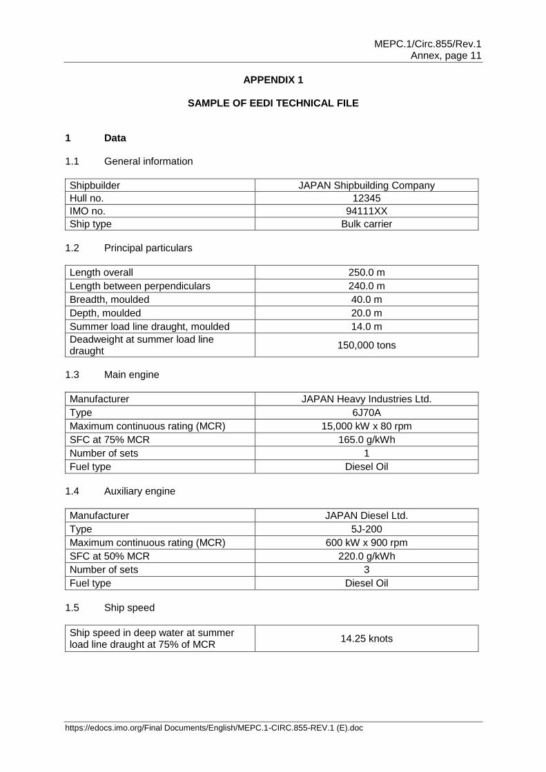
SAMPLE OF EEDI TECHNICAL FILE 1 Data 1.1 General information
Shipbuilder JAPAN Shipbuilding Company
Hull no. 12345
IMO no. 94111XX
Ship type Bulk carrier
1.2 Principal particulars
Length overall 250.0 m
Length between perpendiculars 240.0 m
Breadth, moulded 40.0 m
Depth, moulded 20.0 m
Summer load line draught, moulded 14.0 m
Deadweight at summer load line draught
150,000 tons
1.3 Main engine
Manufacturer JAPAN Heavy Industries Ltd.
Type 6J70A
Maximum continuous rating (MCR) 15,000 kW x 80 rpm
SFC at 75% MCR 165.0 g/kWh
Number of sets 1
Fuel type Diesel Oil
1.4 Auxiliary engine
Manufacturer JAPAN Diesel Ltd.
Type 5J-200
Maximum continuous rating (MCR) 600 kW x 900 rpm
SFC at 50% MCR 220.0 g/kWh
Number of sets 3
Fuel type Diesel Oil
1.5 Ship speed
Ship speed in deep water at summer load line draught at 75% of MCR
14.25 knots

MEPC.1/Circ.855/Rev.1 Annex, page 12
https://edocs.imo.org/Final Documents/English/MEPC.1-CIRC.855-REV.1 (E).doc
2 Power curves The power curves estimated at the design stage and modified after the speed trials are shown in figure 2.1.
Figure 2.1: Power curves
Figure 2.1: Power curves
5,000
7,000
9,000
11,000
13,000
15,000
17,000
12 13 14 15 16 17
Speed / knots
BH
P / k
W
Trial Condition
[Summer load draught]
75% of MCR
14.25 knot
Summer load draught
MEPC.1/Circ.855/Rev.1 Annex, page 13
https://edocs.imo.org/Final Documents/English/MEPC.1-CIRC.855-REV.1 (E).doc
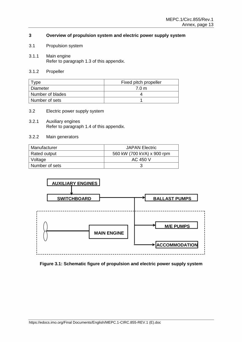
3 Overview of propulsion system and electric power supply system 3.1 Propulsion system 3.1.1 Main engine
Refer to paragraph 1.3 of this appendix. 3.1.2 Propeller
Type Fixed pitch propeller
Diameter 7.0 m
Number of blades 4
Number of sets 1
3.2 Electric power supply system 3.2.1 Auxiliary engines
Refer to paragraph 1.4 of this appendix. 3.2.2 Main generators
Manufacturer JAPAN Electric
Rated output 560 kW (700 kVA) x 900 rpm
Voltage AC 450 V
Number of sets 3
Figure 3.1: Schematic figure of propulsion and electric power supply system
AUXILIARY ENGINES
SWITCHBOARD BALLAST PUMPS
M/E PUMPS
ACCOMMODATION
MAIN ENGINE
MEPC.1/Circ.855/Rev.1 Annex, page 14
https://edocs.imo.org/Final Documents/English/MEPC.1-CIRC.855-REV.1 (E).doc
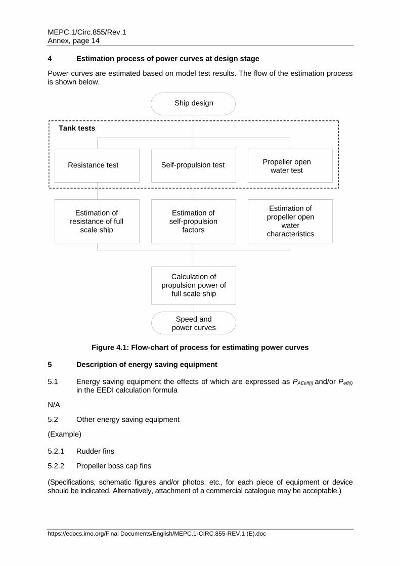
4 Estimation process of power curves at design stage
Power curves are estimated based on model test results. The flow of the estimation process is shown below.
Figure 4.1: Flow-chart of process for estimating power curves 5 Description of energy saving equipment 5.1 Energy saving equipment the effects of which are expressed as PAEeff(i) and/or Peff(i)
in the EEDI calculation formula
N/A
5.2 Other energy saving equipment
(Example) 5.2.1 Rudder fins
5.2.2 Propeller boss cap fins
(Specifications, schematic figures and/or photos, etc., for each piece of equipment or device should be indicated. Alternatively, attachment of a commercial catalogue may be acceptable.)
Tank tests
Estimation of propeller open
water characteristics
Estimation of self-propulsion
factors
Estimation of resistance of full
scale ship
Calculation of propulsion power of
full scale ship
Speed and power curves
Resistance test Propeller open water test
Self-propulsion test
Ship design
MEPC.1/Circ.855/Rev.1 Annex, page 15
https://edocs.imo.org/Final Documents/English/MEPC.1-CIRC.855-REV.1 (E).doc
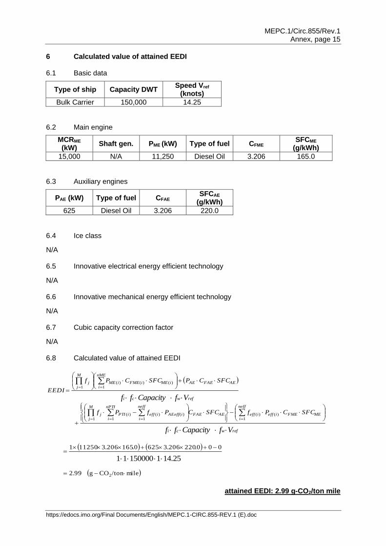
6 Calculated value of attained EEDI 6.1 Basic data
Type of ship Capacity DWT Speed Vref
(knots)
Bulk Carrier 150,000 14.25
6.2 Main engine
MCRME (kW)
Shaft gen. PME (kW) Type of fuel CFME SFCME
(g/kWh)
15,000 N/A 11,250 Diesel Oil 3.206 165.0
6.3 Auxiliary engines
PAE (kW) Type of fuel CFAE SFCAE
(g/kWh)
625 Diesel Oil 3.206 220.0
6.4 Ice class
N/A 6.5 Innovative electrical energy efficient technology
N/A 6.6 Innovative mechanical energy efficient technology
N/A 6.7 Cubic capacity correction factor
N/A 6.8 Calculated value of attained EEDI
mile/tonCOg99.2
125.141500001
000.220206.36250.165206.3112501
2
1)()(
1)()(
1)(
1
1)()()(
1
wrefi
neff
iMEFMEieffieffAEFAE
neff
iiAEeffieff
nPTI
iiPTI
M
jj
wrefi
AEFAEAE
nME
iiMEiFMEiME
M
jj
fVCapacityf
SFCCPfSFCCPfPf
fVCapacityf
SFCCPSFCCPf
EEDI
attained EEDI: 2.99 g-CO2/ton mile
refwci VfCapacityff
refwci VfCapacityff
25.14115000011
MEPC.1/Circ.855/Rev.1 Annex, page 16
https://edocs.imo.org/Final Documents/English/MEPC.1-CIRC.855-REV.1 (E).doc
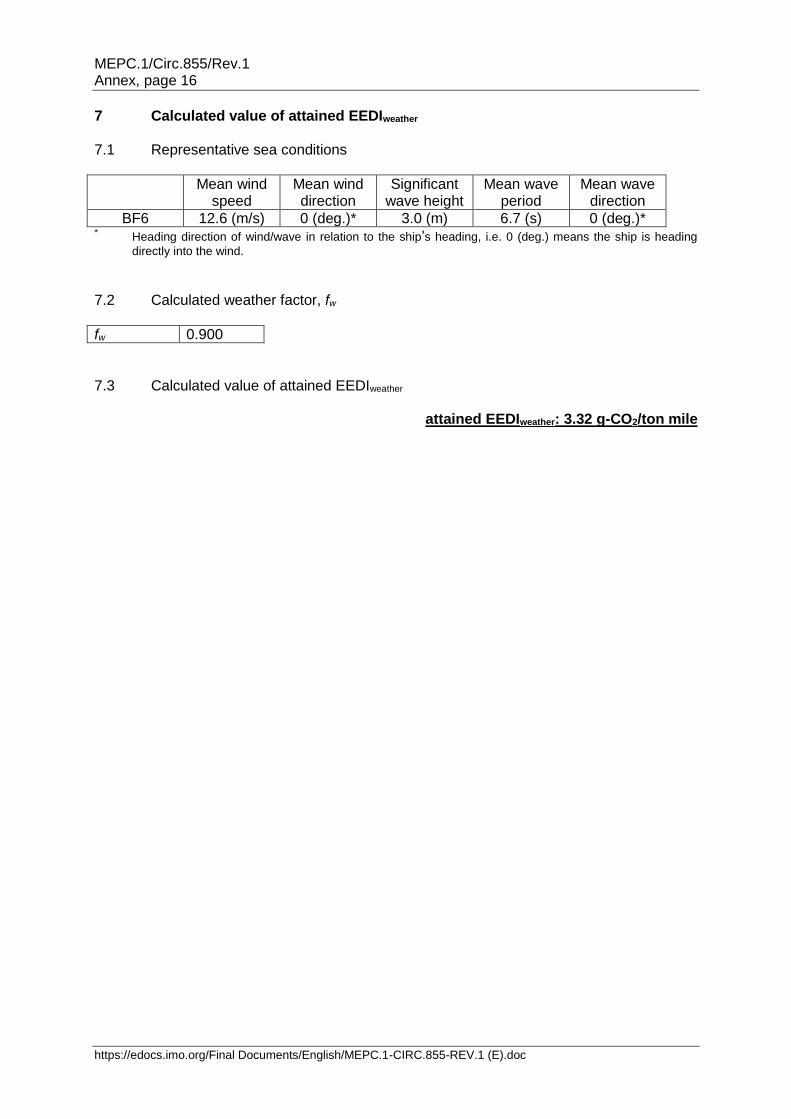
7 Calculated value of attained EEDIweather
7.1 Representative sea conditions
Mean wind speed
Mean wind direction
Significant wave height
Mean wave period
Mean wave direction
BF6 12.6 (m/s) 0 (deg.)* 3.0 (m) 6.7 (s) 0 (deg.)* * Heading direction of wind/wave in relation to the ship's heading, i.e. 0 (deg.) means the ship is heading
directly into the wind.
7.2 Calculated weather factor, fw
fw 0.900
7.3 Calculated value of attained EEDIweather
attained EEDIweather: 3.32 g-CO2/ton mile
MEPC.1/Circ.855/Rev.1 Annex, page 17
https://edocs.imo.org/Final Documents/English/MEPC.1-CIRC.855-REV.1 (E).doc
APPENDIX 2
GUIDELINES FOR VALIDATION OF ELECTRIC POWER TABLES FOR EEDI (EPT-EEDI) 1 INTRODUCTION The purpose of these guidelines is to assist recognized organizations in the validation of Electric Power Tables (EPT) for the calculation of the Energy Efficiency Design Index (EEDI) for ships. As such, these guidelines support the implementation of the EEDI Calculation Guidelines and the Guidelines on survey and certification of the Energy Efficiency Design Index (EEDI). These guidelines will also assist shipowners, shipbuilders, ship designers and manufacturers in relation to aspects of the development of more energy efficient ships and also in understanding the procedures for the EPT-EEDI validation. 2 OBJECTIVES These guidelines provide a framework for the uniform application of the EPT-EEDI validation process for ships for which required auxiliary engine power is calculated under paragraph 2.5.6.4 of the EEDI Calculation Guidelines. 3 DEFINITIONS 3.1 Applicant means an organization, primarily a shipbuilder or a ship designer, which requests the EPT-EEDI validation in accordance with these guidelines. 3.2 Validator means a recognized organization which conducts the EPT-EEDI validation in accordance with these guidelines. 3.3 Validation for the purpose of these guidelines means review of submitted documents and survey during construction and sea trials. 3.4 Standard EPT-EEDI-Form refers to the layout given in appendix 3, containing the EPT-EEDI results that will be the subject of validation. Other supporting documents submitted for this purpose will be used as reference only and will not be subject to validation. 3.5 PAE herein is defined as per the definition in paragraph 2.5.6 of the EEDI Calculation Guidelines. 3.6 Ship service and engine-room loads refer to all the load groups which are needed for the hull, deck, navigation and safety services, propulsion and auxiliary engine services, engine-room ventilation and auxiliaries and ship's general services. 3.7 Diversity factor is the ratio of the "total installed load power" and the "actual load power" for continuous loads and intermittent loads. This factor is equivalent to the product of service factors for load, duty and time. 4 APPLICATION 4.1 These guidelines are applicable to ships as stipulated in paragraph 2.5.6.4 of the EEDI Calculation Guidelines. 4.2 These guidelines should be applied to new ships for which an application for an EPT-EEDI validation has been submitted to a validator.
MEPC.1/Circ.855/Rev.1 Annex, page 18
https://edocs.imo.org/Final Documents/English/MEPC.1-CIRC.855-REV.1 (E).doc
4.3 The steps of the validation process include:
.1 review of documents during the design stage:
.1 check if all relevant loads are listed in the EPT; .2 check if reasonable service factors are used; and .3 check the correctness of the PAE calculation based on the data
given in the EPT;
.2 survey of installed systems and components during construction stage:
.1 check if a randomly selected set of installed systems and components are correctly listed with their characteristics in the EPT;
.3 survey of sea trials:
.1 check if selected units/loads specified in EPT are observed.
5 SUPPORTING DOCUMENTS 5.1 The applicant should provide as a minimum the ship electric balance load analysis. 5.2 Such information may contain shipbuilders' confidential information. Therefore, after the validation, the validator should return all or part of such information to the applicant at the applicant's request. 5.3 A special EEDI condition during sea trials may be needed and defined for each ship and included in the sea trial schedule. For this condition, a special column should be inserted into the EPT. 6 PROCEDURES FOR VALIDATION 6.1 General PAE should be calculated in accordance with the EPT-EEDI Calculation Guidelines. EPT-EEDI validation should be conducted in two stages: preliminary validation at the design stage and final validation during sea trials. The validation process is presented in figure 6.1.

MEPC.1/Circ.855/Rev.1 Annex, page 19
https://edocs.imo.org/Final Documents/English/MEPC.1-CIRC.855-REV.1 (E).doc
Figure 6.1: Basic flow of EPT-EEDI validation process 6.2 Preliminary validation at the design stage 6.2.1 For the preliminary validation at the design stage, the applicant should submit to a validator an application for the validation of EPT-EEDI, inclusive of the EPT-EEDI Form, and all the relevant and necessary information for the validation as supporting documents. 6.2.2 The applicant should supply as a minimum the supporting data and information, as specified in appendix A (to be developed). 6.2.3 The validator may request from the applicant additional information to that contained in these guidelines, as necessary, to enable the validator to examine the calculation process of the EPT-EEDI. The estimation of the ship EPT-EEDI at the design stage depends on each applicant's experience, and it may not be practicable to fully examine the technical aspects and details of each machinery component. Therefore, the preliminary validation should focus on the calculation process of the EPT-EEDI that should follow best marine practices.
Note: A possible way forward for more robust validation is to establish a standard methodology of deriving the ship EPT by setting standard formats as agreed and used by industry.
Applicant
(Primarily shipbuilder or ship designer)
Validator (Recognized organization such as
class society)
Development of electric load analysis
Preliminary validation (Preliminary ship electric load analysis and
supporting documents)
Application for EPT-EEDI preliminary validation
Issuance of preliminary validation certificate
Preparation and submission of final EPT-EEDI
Check of consistency of preliminary and final EPT
Preparation of data for final validation
at sea trials
Modification of EPT-EEDI
Final validation at sea trials by check of predicted power requirements
Issuance of final validation certificate
Submission of EPT-EEDI certificate for EEDI verification
MEPC.1/Circ.855/Rev.1 Annex, page 20
https://edocs.imo.org/Final Documents/English/MEPC.1-CIRC.855-REV.1 (E).doc
6.3 Final validation 6.3.1 The final validation process should as a minimum include a check of the ship electric load analysis to ensure that all electric consumers are listed. Their specific data and the calculations in the power table itself are correct and are supported by sea trial results. If necessary, additional information has to be requested. 6.3.2 For the final validation, the applicant should revise the EPT-EEDI Form and supporting documents as necessary, by taking into account the characteristics of the machinery and other electrical loads actually installed on board the ship. The EEDI condition at sea trials should be defined and the expected power requirements in these conditions documented in the EPT. Any changes within the EPT from design stage to construction stage should be highlighted by the shipyard. 6.3.3 The preparation for the final validation includes a desk top check comprising:
.1 consistency of preliminary and final EPT; .2 changes of service factors (compared to the preliminary validation); .3 all electric consumers are listed; .4 their specific data and the calculations in the power table itself are correct; and .5 in case of doubt, component specification data is checked in addition.
6.3.4 A survey prior to sea trials is performed to ensure that machinery characteristics and data as well as other electric loads comply with those recorded in the supporting documents. This survey does not cover the complete installation but selects randomly a number of samples. 6.3.5 For the purpose of sea trial validation, the surveyor will check the data of selected systems and/or components given in the special column added to the EPT for this purpose or the predicted overall value of electric load by means of practicable measurements with the installed measurement devices. 7 ISSUANCE OF THE EPT-EEDI STATEMENT OF VALIDATION 7.1 The validator should stamp the EPT-EEDI Form as "Noted" having validated the EPT-EEDI in the preliminary validation stage, in accordance with these guidelines. 7.2 The validator should stamp the EPT-EEDI Form as "Endorsed" having validated the final EPT-EEDI in the final validation stage in accordance with these guidelines.

MEPC.1/Circ.855/Rev.1 Annex, page 21
https://edocs.imo.org/Final Documents/English/MEPC.1-CIRC.855-REV.1 (E).doc
APPENDIX 3
ELECTRIC POWER TABLE FORM FOR ENERGY EFFICIENCY DESIGN INDEX (EPT-EEDI FORM) AND STATEMENT OF VALIDATION
Ship ID: IMO no.: Ship's name: Shipyard: Hull no.:
Applicant: Validation stage:
Name: Preliminary validation Address: Final validation
Summary results of EPT-EEDI
Load group
Seagoing condition EEDI Calculation guidelines
Remarks Continuous load (kW)
Intermittent load (kW)
Ship service and engine-room loads
Accommodation and cargo loads
Total installed load
Diversity factor
Normal seagoing load
Weighted average efficiency of generators
PAE
Supporting documents
Title ID or remarks
Validator details: Organization: Address:
This is to certify that the above-mentioned electrical loads and supporting documents have been reviewed in accordance with EPT-EEDI Validation Guidelines and the review shows a reasonable confidence for use of the above PAE in EEDI calculations.
Date of review: Statement of validation no.
This statement is valid on condition that the electric power characteristics of the ship do not change. Signature of Validator
Printed name:
___________
Top Related