


Languages
Pages
Legal


1
PASSIVE REPEATERS FOR INDOOR SIGNAL RECOVERING
Hristo D. Hristov, Rodolfo Feick, Danilo Torres and Walter Grote
Index terms: wireless communications, mobile communications, propagation
Abstract
The radio signal coverage of indoor areas poses a particularly complex problem in buildings with
heavily reinforced concrete or metallic walls, which introduce great attenuation. In these
particular conditions, active or passive repeater systems can be implemented for recovering the
indoor signal to the level of normal reception. In this paper, we have shown theoretically and
demonstrated experimentally the potential for an important improvement of indoor signal
coverage by use of a low-cost on-wall passive repeater for the 900-MHz cellular band. It
consisted of outside and inside 8-dBi-gain antennas, mounted on a very lossy exterior building
wall, and connected through a hole by a piece of coaxial cable and a variable phase shifter in
series. We evaluated the effect of the phase shifter on the indoor signal distribution both
theoretically and empirically. The average signal recovering efficiency in a room of size 2.6m x
4.6m ranges from 15-17dB near the repeater to about 3 dB at a distance 4 m from the repeater.
1. INTRODUCTION
Assuring adequate signal coverage of indoor areas is an important problem for cellular systems in
regions where buildings have high attenuation walls. Active repeaters are often used to solve the
problem [1], but in addition to their added cost they need a power supply and maintenance. Also,
the amplified signal has the potential of creating significant interference in those areas that are
already well covered by a direct signal of the same frequency channel.

2
In this work we have explored the potential for field coverage improvement by means of two-
antenna passive repeaters, similar to those employed in the microwave radio relay links years ago
for redirection of wave propagation over hilly terrain [2]. The building passive repeater is a
device, which basically consists of two antennas, connected by a cable. In addition, we
introduced a novel element to the passive repeater scheme, a phase shifter, aimed at optimizing
indoor signal distribution.
Our recent simplified theoretical study [3], has shown that for wall attenuation of less than 10-12
dB (infinite in extent brick walls, single mesh reinforced concrete walls, wooden walls, etc.), the
signal enhancement due to the passive repeater with medium gain antennas is moderate.
Significant benefits can only be expected at limited ranges or by using high gain antennas at the
expense of angular coverage. For the case of a high loss wall however, with attenuation bigger
than 20-25 dB, a considerable improvement in indoor signal coverage can be easily achieved.
We propose here three different schemes of building through-wall passive repeaters, but only one
of them is analyzed theoretically and studied experimentally: the on-wall mounted passive
repeater. It comprises two equal planar antennas, inside and outside, connected through a hole by
a piece of cable and a variable phase shifter in series. The average recovering efficiency obtained
experimentally in a multipath environment (a small furnished room of size 2.6m x 4.6m ranges),
ranges from 15-17 dB near the repeater to about 3dB at a distance 4m from it.
Passive repeaters can of course not be expected to substitute in all cases the need for active radio
devices that cover larger areas and that will radiate through windows and other low loss sections
of the same construction but as will be seen, under certain conditions they provide significant
signal improvement, particularly when limited areas (“hot spots”) must be covered.
3
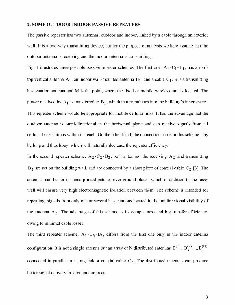
2. SOME OUTDOOR-INDOOR PASSIVE REPEATERS
The passive repeater has two antennas, outdoor and indoor, linked by a cable through an exterior
wall. It is a two-way transmitting device, but for the purpose of analysis we here assume that the
outdoor antenna is receiving and the indoor antenna is transmitting.
Fig. 1 illustrates three possible passive repeater schemes. The first one, 1A - 1C - 1B , has a roof-
top vertical antenna 1A , an indoor wall-mounted antenna 1B , and a cable 1C . S is a transmitting
base-station antenna and M is the point, where the fixed or mobile wireless unit is located. The
power received by 1A is transferred to 1B , which in turn radiates into the building’s inner space.
This repeater scheme would be appropriate for mobile cellular links. It has the advantage that the
outdoor antenna is omni-directional in the horizontal plane and can receive signals from all
cellular base stations within its reach. On the other hand, the connection cable in this scheme may
be long and thus lossy, which will naturally decrease the repeater efficiency.
In the second repeater scheme, 2A - 2C - 2B , both antennas, the receiving 2A and transmitting
2B are set on the building wall, and are connected by a short piece of coaxial cable 2C [3]. The
antennas can be for instance printed patches over ground plates, which in addition to the lossy
wall will ensure very high electromagnetic isolation between them. The scheme is intended for
repeating signals from only one or several base stations located in the unidirectional visibility of
the antenna 2A . The advantage of this scheme is its compactness and big transfer efficiency,
owing to minimal cable losses.
The third repeater scheme, 3A - 3C - 3B , differs from the first one only in the indoor antenna
configuration. It is not a single antenna but an array of N distributed antennas (1)3B , (2)
3B ,..., (N)3B
connected in parallel to a long indoor coaxial cable 3C . The distributed antennas can produce
better signal delivery in large indoor areas.
4
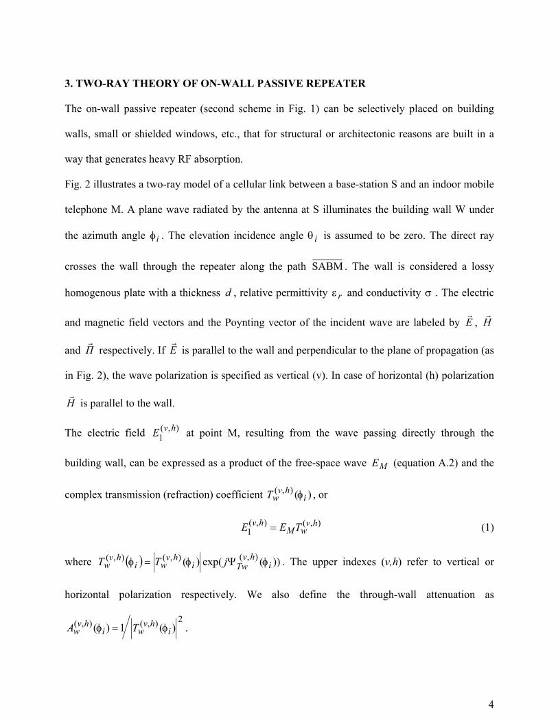
3. TWO-RAY THEORY OF ON-WALL PASSIVE REPEATER
The on-wall passive repeater (second scheme in Fig. 1) can be selectively placed on building
walls, small or shielded windows, etc., that for structural or architectonic reasons are built in a
way that generates heavy RF absorption.
Fig. 2 illustrates a two-ray model of a cellular link between a base-station S and an indoor mobile
telephone M. A plane wave radiated by the antenna at S illuminates the building wall W under
the azimuth angle iφ . The elevation incidence angle iθ is assumed to be zero. The direct ray
crosses the wall through the repeater along the path SABM . The wall is considered a lossy
homogenous plate with a thickness d , relative permittivity rε and conductivity σ . The electric
and magnetic field vectors and the Poynting vector of the incident wave are labeled by Er
, Hr
and Πr
respectively. If Er
is parallel to the wall and perpendicular to the plane of propagation (as
in Fig. 2), the wave polarization is specified as vertical (v). In case of horizontal (h) polarization
Hr
is parallel to the wall.
The electric field ),(1
hvE at point M, resulting from the wave passing directly through the
building wall, can be expressed as a product of the free-space wave ME (equation A.2) and the
complex transmission (refraction) coefficient )(),(i
hvwT φ , or
),(),(1
hvwM
hv TEE = (1)
where ( ) ))(exp()( ),(),(),(i
hvTwi
hvwi
hvw jTT φΨφφ = . The upper indexes (v,h) refer to vertical or
horizontal polarization respectively. We also define the through-wall attenuation as
2),(),( )(1)( ihv
wihv
w TA φφ = .
5
For given d , rε and σ , ( )ihv
wT φ),( and )(),(i
hvwA φ are easily calculated [4].
The field at each indoor point M is found as a vector sum of the field ),(1
hvE and the field 2E
radiated by antenna B, i.e. in this simplified analysis it is assumed that the secondary waves
reflected and transmitted by the other building walls and indoor objects are negligible. Depending
on the wave polarization the total field is written as )(2
)(1
)( vvv EEE += , for vertical polarization,
and as φφ coscos )(2
)(1
)( hi
hh EEE += , for horizontal polarization.
The analysis that follows is for vertical polarization only, the case of horizontal polarization can
be treated in a similar manner. By use of equation (A.8) the field 2E produced by the on-wall
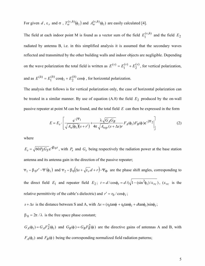
passive repeater at point M can be found, and the total field E can then be expressed in the form
( )( )
+
+
′+⋅= 2
1 j-j-
)e()()(4
e ΨΨ
φφ∆π
λφ BiA
rep
BA
iws FF
rssAGG
rsAEE (2)
where
sSSs GPE 0-je60 β= , with sP and sG being respectively the radiation power at the base station
antenna and its antenna gain in the direction of the passive repeater;
( )ir φΨβΨ −′= 01 and ( ) ΦΨ Ψε∆β −++= rds r02 are the phase shift angles, corresponding to
the direct field 1E and repeater field 2E ; )/)sin(1/(cos/ 2rcit ddt εφφ −== , ( rcε is the
relative permittivity of the cable’s dielectric) and irr φcos/0=′ ;
ss ∆+ is the distance between S and A, with iti drs φφφφ∆ sin)tantanrtan( 00 ++= ;
λπβ /20 = is the free space phase constant;
)()( 2iAAiA FGG φφ = and )()( 2 φφ BBB FGG = are the directive gains of antennas A and B, with
)( iAF φ and )(φBF being the corresponding normalized field radiation patterns;

6
repA is the total attenuation factor, which takes into account the antenna, cable and mismatch
loss.
We next define the signal recovering efficiency (or gain) as a power ratio g at the receiver point
M, which gives the local increase (‘amplification’) or decrease (‘attenuation’) of the power
density at the receiver point M due to the passive repeater
2
1EEg = (3)
If the transmitter and receiver points S and M are at positions normal to the repeater, i.e. if
0== φφi , then bearing in mind that 0rs >> and 0rr = , the power ratio expression can be
simplified to
( ) 20
20 cos21 rQrQg ++= Ψ (4)
where
ΦΨΨΨΨ +−−= wrep (5)
and
BArep
w GGAAQ
πλ
4= (6)
For the case of real antenna impedances and low mismatch, the phase-delay angle is equal to
drccrep εβΨΨ 0== . As Q is always a positive quantity, it is evident from (4) that the
maximum value of the recovering efficiency g is obtained for 0=Ø , or for
repw ΨΨΨΦ += (7)
and is given by the following simple expression
2
0max 1
+=
rQg (8)

7
For a specific wall, the passive repeater can be tuned for maximum power at the mobile receiver.
The repeater delay angle repΨ is easily calculated. For a known wall structure and electric
parameters the transmission phase angle wΨ is also computable. Thus, according to equation (7)
the phase-shifter angle can be set to the optimum value of ΦΨ . If however, the wall is not
specified, the optimum value of ΦΨ can be found only by indoor field trials. Also in typical
practical cases, multipath propagation will result in a much more complex interference
environment making optimum angle prediction very difficult as will be illustrated by our
empirical study.
4. NUMERICAL ANALYSIS OF ON-WALL PASSIVE REPEATER
To provide numerical examples for the improvement in signal coverage that can be expected in
real situations, we have calculated and contrasted the recovering efficiency for three specific
walls of thickness 28.0=d m and infinite extent. It was assumed that these walls can be modeled
with acceptable accuracy as homogeneous structures [3]. The incident wave is assumed to be
vertically polarized. The walls are described as follows.
(a) brick wall with electric parameters 5.4=rε and 02.0=σ S/m;
(b) double steel-mesh reinforced concrete wall with 7=rε and 1.0=σ S/m
(c) extremely lossy (shielded) wall with 7=rε 3.0=σ S/m.
Reasonable practical values are chosen for the following repeater parameters: 20=AG dB,
10=BG dB and 3.1=repA dB.
Table 1 lists the computed values of )(vwA and v
wΨ (normal wave incidence) of the above walls
for two cellular frequencies: 0.9GHz and 1.8GHz.. The electric parameters rε and σ are
assumed to be the same for both frequencies.
8
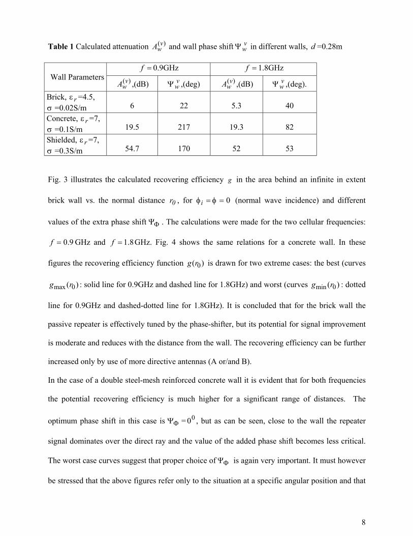
Table 1 Calculated attenuation )(vwA and wall phase shift v
wΨ in different walls, d =0.28m
=f 0.9GHz =f 1.8GHzWall Parameters )(v
wA ,(dB) vwΨ ,(deg) )(v
wA ,(dB) vwΨ ,(deg).
Brick, rε =4.5,σ =0.02S/m 6 22 5.3 40Concrete, rε =7,σ =0.1S/m 19.5 217 19.3 82Shielded, rε =7,σ =0.3S/m 54.7 170 52 53
Fig. 3 illustrates the calculated recovering efficiency g in the area behind an infinite in extent
brick wall vs. the normal distance 0r , for 0== φφi (normal wave incidence) and different
values of the extra phase shift ΦΨ . The calculations were made for the two cellular frequencies:
9.0=f GHz and 8.1=f GHz. Fig. 4 shows the same relations for a concrete wall. In these
figures the recovering efficiency function )( 0rg is drawn for two extreme cases: the best (curves
)( 0max rg : solid line for 0.9GHz and dashed line for 1.8GHz) and worst (curves )( 0min rg : dotted
line for 0.9GHz and dashed-dotted line for 1.8GHz). It is concluded that for the brick wall the
passive repeater is effectively tuned by the phase-shifter, but its potential for signal improvement
is moderate and reduces with the distance from the wall. The recovering efficiency can be further
increased only by use of more directive antennas (A or/and B).
In the case of a double steel-mesh reinforced concrete wall it is evident that for both frequencies
the potential recovering efficiency is much higher for a significant range of distances. The
optimum phase shift in this case is ΦΨ = 00 , but as can be seen, close to the wall the repeater
signal dominates over the direct ray and the value of the added phase shift becomes less critical.
The worst case curves suggest that proper choice of ΦΨ is again very important. It must however
be stressed that the above figures refer only to the situation at a specific angular position and that

9
usually the goal is improvement of area coverage. As will be discussed later, our empirical results
show that in a practical case, with significant multipath propagation, the average improvement
over an area is little affected by the choice of phase shift. This is due to the fact that the phase
shift basically changes the position of the regions of constructive and destructive interference, not
their size.
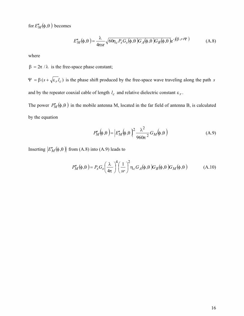
The recovering efficiency as a function of the offset distance y (see Fig .2) is illustrated in Fig.
5, for the double steel-mesh reinforced concrete wall (solid line), and for the shielded wall
(dashed line). Here the distance 0r from the receiver point M to the passive repeater is kept
constant ( 20 =r m) and 00=ΦΨ . The frequency is assumed to be 9.0 GHz. For the case of a
reinforced concrete wall the recovering efficiency is about 10dB in the offset distance range
6.0±=y m, while for the shielded wall it has much higher values: 40dB for 0=y m and bigger
than 25 dB for in the range 10±=y m. For the latter case the direct signal is practically zero, and
naturally the phase shifter becomes superfluous.
.
5. EXPERIMENTAL STUDY OF TWIN-ANTENNA PASSIVE REPEATER
Complex conditions, such as the effect of multiple arriving wavefronts and reflecting objects,
which are difficult to analyze theoretically and which will vary with position inside a room are
best treated through an empirical study to collect statistically relevant data. Our procedures
described below concentrated on this aspect, providing the results of a real implementation and
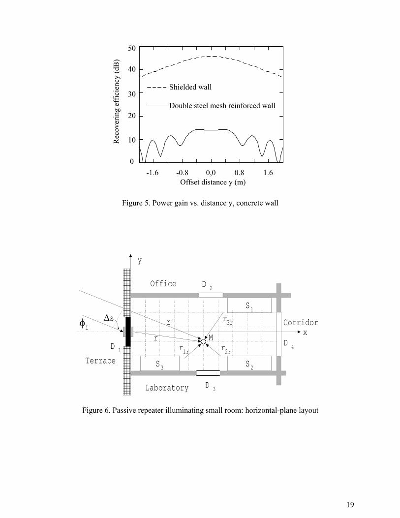
its comparison with the simplified theoretical model. A passive repeater illuminating a small
room is sketched in Fig. 6. Shown are the horizontal room layout and the repeater ray-
interference scheme at the receiver point M (direct or transmission ray r′ , repeater ray r and
three reflected rays rrr rrr 321 and , ). The room has a width of 2.6m and a length of 4.6m and
comprises an exterior brick and mortar wall with a metal door D1 and partition walls with doors

10
D2, D3 and D4. The ceiling and the floor are made of reinforced concrete. S1, S2 and S3 are metal
stands of size 1.8m (height) x 1.20m x 0.50 m each. The passive repeater device under
examination consisted of two equal plane-reflector antennas A and B with vertical polarization,
each of size 21cm x 21cm x 5cm, a nominal gain of 8 dB at 900 MHz, VSWR=1.5 and a
horizontal-plane beamwidth of 80 degrees. The repeater antennas were mounted on the metal
door, at a height of 1.6 m above the floor. In order to increase the through wall attenuation,
simulating a high loss wall, the outer side of the wall was loosely covered (shielded) by an anti-
mosquito type metal mesh.
The power gain associated with the use of the passive repeater was determined for the case of a
continuous wave signal. The procedure involved first measuring the received power in the chosen
indoor area, under normal conditions, i.e. when the passive repeater was switched-off. This was
done over a wide range of positions in the room according to a square measurement grid of a size
equal to one wavelength, or 33.3cm. Both, the transmitter antenna and receiver antenna were held
at the repeater’s height. The transmitter antenna was placed outdoors at a distance of 7.5m from
the shielded wall.
An element of uncertainty in any real situation is the angle of arrival of the outside signal with
respect to the boresight of the receiving antenna. Any practical repeater for cellular telephony
would be expected to cover a wide azimuth range as the base station position serving a call is not
usually known. That is why, the measurements included positioning the transmitter antenna to
“see” the passive repeater from several different angles iφ ranging between 0º and 60º, with an
increment of 10º. Because the antennas have relatively low directivity, there exists a potential for
significant multipath signal propagation, a condition representative of an urban environment. The
measured values without the repeater were contrasted with the theoretical free space received
power. This provides information on the combined effect of the wall obstructing the direct path,
and the multipath interference due to the surrounding building elements and furniture. For each
11
position inside the room, the corresponding value of received power with the repeater switched-
on was subsequently measured. An extra phase-shift, φΨ =0º, 90º, 180º or 270º, was introduced
by means of the phase-shifter in order to test the influence of this parameter. For a plane wave
incident on an infinite wall, in an environment devoid of multipath effects the optimum phase
shift can be evaluated. However, in the case of a restricted exterior wall in a realistic building
room, the presence of multipath propagation implies that the prediction of the influence of the
extra phase shift will be virtually impossible and can only be evaluated empirically.
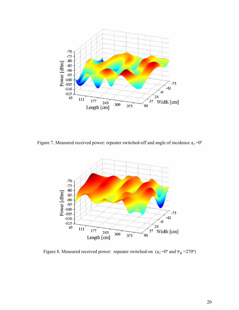
Fig. 7 illustrates the distribution of the power received from the outdoor test transmitter as
measured inside the room, when the passive repeater is switched-off. The transmitter antenna is
positioned at =iφ 0º. The high loss wall with the metal door and repeater is parallel to the yz
plane, x=0 (Fig. 6) and the position of the repeater corresponds to the coordinate y=0. Multipath
interference is quite pronounced and the power actually increases as one moves away from the
wall, indicating that the signal is also entering through the neighboring rooms, with lower loss
outside walls. On the average, the measured power level values near the exterior are 26-28 dB
lower than predicted by the free space condition.
Fig. 8 presents the power measurements in the same room, if the passive repeater is switched-on
and for a normal incidence of the outside wave. Significantly higher power levels are observed
with multipath fluctuations that are similar to those when the repeater is switched-off.
Figure 9 shows the theoretical levels calculated by use of the simple model discussed before,
considering an infinite wall, with an attenuation of 28dB. The calculations were done for a
normal wave incidence. Obviously, the multi-ray fluctuations are not present here, but it is
interesting to observe that the mean power levels do not differ very much from those in Fig. 8,
especially up to distances of 2-3 m. At very short range where the repeater power is dominant
both graphs are quite similar.
12
For Fig. 8 and Fig. 9 the extra phase shift between repeater antennas was chosen to be 270º, a
value that results in good gain and smooth coverage. Measurements performed for other values of
the phase shift show similar results. As expected, it was observed that in the region where the
repeater power dominates, the phase shift is of little consequence. In contrast, in the region where
the repeater output is comparable to the signals entering through the walls, the diagram changes
significantly. Interestingly though, it was found that on the average, the total area with relevant
signal gain tends to remain unchanged and thus the search for an “optimal phase shift” will be
limited to cases where only specific points in a room need signal improvement and where
multipath propagation plays no significant role.
The large amount of collected data, and the variations that are to be expected for these type of
measurements, requires the use of statistical processing of data in order to be able to draw general
conclusions. From the measured power data we calculated the average recovering efficiency at a
given distance from the repeater wall: gav (dB)=P(dBm)–P1 (dBm). Here P and P1 are,
respectively, the average (in dBm) power levels that correspond to the switched-on and switched-
off conditions of the passive repeater. The averaging was done over all angles of incidence and
for all measurement points in each mesh line parallel to the y-axis (Fig. 6). The average
recovering efficiency curves as function of distance from the repeater to the door D4 are drawn in
Fig. 10, for two values of the phase shift ΦΨ : 90º–dashed line (best case) and 180º– dashed
dotted line (worst case). The continuous line in the same figure illustrates as a reference, the
theoretical function )( 0rg , for the ideal case of a transmitter and receiver located on the axis of
the repeater antenna beams. It was calculated by use of equation (3), for wA =28dB,
3.1=repA dB, o90=ΦΨ and BA GG = =8 dB. As can be seen, on average, the difference
between best and worst case is not big, far less than the extreme conditions depicted in figures 3
and 4. It is evident that the signal average signal recovering efficiency oscillates and decreases
13
quickly with the distance, ranging from about 15 dB near the repeater, to about 3 dB at the far
end of the room.
CONCLUSIONS
We have shown theoretically and demonstrated experimentally the potential for a significant
improvement of indoor signal coverage by use of an on-wall-wall passive repeater for the 900-
MHz cellular band. To the classical repeating scheme a new element was introduced – a tuning
phase shifter – and its influence evaluated. For the idealized case of an infinite homogeneous the
two-ray interference scheme predicts that the phase shifter role depends much on the wall
character: it can be an important element for low and medium loss walls (brick, single mesh
reinforced concrete, wood, etc); for very high loss concrete or metallic walls its role is of little
significance. Our empirical work confirmed that for the specific case of a small building room
with a high loss exterior wall and a realistic indoor environment, significant signal recovering is
achieved, ranging from 15-17 to about 3 dB depending on the position in the room. The effect of
the extra phase shift is important when certain specific zones in the room need signal
improvement. Multipath propagation tends in practice to make the choice uncritical when larger
areas need to be covered, as improvements in a certain region due to the choice of the proper
phase shift are offset by deterioration in other areas. The feasibility of predicting optimum values
for the phase shift is restricted to cases where a simple propagation environment makes a
theoretical analysis practical.
While our analysis stressed the improvement in signal coverage over a complete area (mobile
situation), for the case of fixed-terminal communication systems the signal level can be further
increased using more directive repeater antennas or antenna arrays that cover only certain angular
positions.
14
ACKNOWLEDGEMENT
The authors acknowledge the support received by the Chilean National Science Agency
CONICYT through the Fondecyt project # 1010129/2001.
REFERENCES
1. Repeater Technologies, http://www.repeaters.com
2. G. Z Aizenberg and B. G. Yampolskii, “Passive repeaters for radio relay
links”, Svyaz Publ., 1973 (in Russian).
3. H. D. Hristov, R. Feick, and W. Grote, “Improving indoor signal coverage
by use of through wall passive repeaters”, IEEE Antennas Propag. Soc. Int. AP-
S Symp. Digest, Boston, vol. 2, 2001, pp. 158-161.
4. W. D. Burnside and K. W. Burgener “High frequency scattering by a thin
lossless dielectric slab”, IEEE Trans. A P-S, vol 31, Nº 1, 1983, pp. 104-110.
Appendix
Basic Equations for Passive Signal Repeating
The power MP′ received by the receiver antenna M in the case of direct free space propagation
along a path rs + is found by the Friis wireless link equation, or
( ) ( ) ( )θφθφπλ
θφ ,,)(4
,2
MSSM GGPrs
P
+
=′ (A.1)
where the SP is the power radiated by the base-station antenna S; ( ) ( )θφθφ ,, 2SSS FGG = and
( ) ( )θφθφ ,, 2MMM FGG = are gain functions expressed by their maximum values SG and MG ,
and normalized field radiation patterns ( )θφ ,AF and ( )θφ ,BF , respectively.

15
The corresponding electric field ME ′ at the point M is given by
( ) ( ) ).(,60, rsjSS
M ers
GPE +−
+=′ βθφ
θφ (A.2)
If the signal is not propagating directly from point S to point M, but through a passive two-
antenna repeater (Fig. 2 ), the power at the mobile antenna output can be found as follows.
The power AP in the receiving repeater antenna A can be also found by use of the Friis equation,
applied to the path s only, or
( ) ( ) ( )θφθφπλ
θφ ,,4
,2
AssA GGs
PP
= (A.3)
with ( ) ( )θφθφ ,, 2AAA FGG = being the gain pattern of antenna A.
The power at the input of transmitting repeater antenna B is proportional to the power AP , or
( ) ( )θφηθφ ,, AcB PP = (A.4)
where the total cable efficiency cη , calculated by the equation
( )( )22-2 11e c BAl
c c ρρη α −−= (A.5)
cη is a product between the cable loss efficiency cll c-2e αη = and the match efficiencies 21 Aρ−
and 21 Bρ− . Here Aρ and Bρ are the reflection coefficients at the ports of repeater antennas.
After inserting AP from (A.3) into (A.4) we find
( ) =θφ ,BP ( ) ( ) ( )θφθφθφηπλ ,,,
4
2
BAsSc GGGPs
(A.6)
The electric field ( )θφ ,ME ′′ at the receive point M can expressed in the form
( ) ( ) rjBBM e
rGP
E .,60, βθφθφ −=′′ (A.7)
and after replacing ( )θφ ,BP by its expression from (A.6) the equation
16
for ( )θφ ,ME ′′ becomes
( ) ( ) ( ) ( ) ( )Ψβθφθφθφηπλ
θφ +=′′ rBAsscM GGGPE .j-e,,,60
sr4, (A.8)
where
λπβ /2= is the free-space phase constant;
)( cr ls εβΨ += is the phase shift produced by the free-space wave traveling along the path s
and by the repeater coaxial cable of length cl and relative dielectric constant rε .
The power ( )θφ ,MP ′′ in the mobile antenna M, located in the far field of antenna B, is calculated
by the equation
( ) ( ) ( )θφπ
λθφθφ ,
960,, 2
22MMM GEP ′′=′′ (A.9)
Inserting ( )θφ ,ME ′′ from (A.8) into (A.9) leads to
( ) ( ) ( ) ( )θφθφθφηπλ
θφ ,,,14
,24
MBAcssM GGGsr
GPP
=′′ (A.10)

17
M
A1
B1
C1
A2 B2C2
A3
s3
s1
s
C3
B3(1) B3
(n)B3(2)
s2
S
Figure 1. Passive repeater schemes
����������������������������������������������������������������������������������������������������������������������������������������������������������������������������������������������������������������������������������������������������������������������������������������������������������������������������������������������������������������������������������������������������������������������������������������������������������������������������������������������������
���
S
M
φi
φi
φi
φ
r'
r
d
FΑ(φi )
FB(φ )
ΨΦ
BA
∆s
s
s
y
xr0
φt
Π
HE
Figure 2. On-wall passive repeater geometry: two-ray scheme

18
gmin
gmax
Rec
over
ing
effic
ienc
y (d
B)
-8
-6-4-2
0
8
642
0.5 1.0 2.0 3.0 4.0 5.0Normal distance (m)
ψΦ=160º
ψΦ=0º
ψΦ=310º
ψΦ=90º
Figure 3. Recovering efficiency vs. distance r0 for brick wall (f=0.9GHz solid and dotted,
f=1.8GHz dashed and dash-dotted)
gmax
Rec
over
ing
effic
ienc
y (d
B)
-12-8-4
0
16
1284
-16-20
20
0.5 1.0 2.0 3.0 4.0 5.0Normal distance (m)
ψΦ= 0º
ψΦ= 180ºψΦ=180º
ψΦ= 0º
gmin
Figure 4. Recovering efficiency vs. distance r0 for concrete wall (f=0.9GHz solid and dotted,
f=1.8GHz dashed and dash-dotted)
19
0
30
10
20
40
50
Rec
over
ing
effic
ienc
y (d
B)
-1.6 -0.8 0,0 0.8 1.6Offset distance y (m)
Shielded wall
Double steel mesh reinforced wall
Figure 5. Power gain vs. distance y, concrete wall
S3 S2
S1
D 2
D 3
Corridor
D 4
Laboratory
Office
xMr
r'
r1r r2r
r3r����������
����������D 1
Terrace
y
φi∆s
Figure 6. Passive repeater illuminating small room: horizontal-plane layout
20
Figure 7. Measured received power: repeater switched-off and angle of incidence iφ =0º
Figure 8. Measured received power: repeater switched-on ( iφ =0º and φΨ =270º)

21
Figure 9. Theoretical received power with passive repeater switched-on ( iφ =0º and φΨ =270º)
0
3
6
9
12
15
18
Distance (cm)
Ave
rage
reco
verin
g ef
ficie
ncy
(dB
)
100 200 300 400
Figure 10. Average recovering efficiency g vs. normal distance 0r of on-wall passive repeater:
experimental curves, for two phase shift values: ΦΨ =90º (dashed line) and ΦΨ =180º (dash-
dotted line), and theoretical curve (solid line) for ΦΨ =90º, receiver and transmitter on axis of
antenna lobes.
Top Related