


Languages
Pages
Legal


Oxygen Analyser
Model 1632
August 2007

August 2007
2 1632 Oxygen Transmitter

August 2007
1632 Oxygen Transmitter 3
CONTENTS
1. SPECIFICATIONS
2. DESCRIPTION
3. INSTALLATION & COMMISSIONING
4. OPERATORS FUNCTIONS - ALARMS
5. SETTING UP THE TRANSMITTER
6. MAINTENANCE
APPENDICES
1. CONSTITUENT VALUES FOR VARIOUS FUELS
2. PROBE OR SENSOR EMF TABLES
3. LOG OXYGEN SCALE
4. SAMPLE LOG PRINT OUT
5. CIRCUIT SCHEMATIC
6. MODBUS™ REGISTER MAP
DECLARATION OF CONFORMITY (LAST PAGE)
Note: This manual includes software modifications up to Version 2.31, 14
th August 2007
© Copyright NOVATECH CONTROLS PTY. LTD. - 1996 - 2006
This manual is part of the product sold by Novatech Controls Pty. Ltd. ("Novatech Controls") and is provided to the
customer subject to Novatech Controls' conditions of sale, a copy of which is set out herein. Novatech Controls' liability
for the product including the contents of this manual is as set out in the conditions of sale.
All maintenance and service of the product should be carried out by Novatech Controls' authorised dealers.
This manual is intended only to assist the reader in the use of the products. This manual is provided in good faith but
Novatech Controls does not warrant or represent that the contents of this manual are correct or accurate. It is the
responsibility of the owner of the product to ensure users take care in familiarising themselves in the use, operation and
performance of the product.
The product, including this manual and products for use with it, are subject to continuous developments and
improvement by Novatech Controls. All information of a technical nature and particulars of the product and its use
(including the information in this manual) may be changed by Novatech Controls at any time without notice and without
incurring any obligation. A list of details of any amendments or revisions to this manual can be obtained upon request
from Novatech Controls. Novatech Controls welcome comments and suggestions relating to the product including this
manual.
Neither the whole nor any part of the information contained in, or the product described in, this manual may be adapted
or reproduced in any material form except with the prior written approval of Novatech Controls Pty. Ltd.
All correspondence should be addressed to:
Technical Enquires
Novatech Controls (Aust.) Pty Ltd
309 Reserve Road
Cheltenham Victoria 3192 Phone: Melbourne +61 3 9585 2833
Australia Fax: Melbourne +61 3 9585 2844
Website: www.novatech.com.au

August 2007
4 1632 Oxygen Transmitter
USING THIS MANUAL
The Novatech 1632 Oxygen Transmitter has a variety of user-selectable functions.
They are simple to use because each selection is menu driven. For options you are not sure about; read the manual on
that particular item.
Please read the safety information below and the ‘Installation’ section before connecting power to the transmitter.
CAUTION 1 The probe or sensor heater is supplied with mains voltage. This supply has electrical shock danger to maintenance
personnel. Always isolate the transmitter before working with the probe or sensor, gas solenoids, or the transmitter.
The EARTH wire (green) from a heated probe or sensor must ALWAYS be connected to earth.
CAUTION 2 Combustion or atmosphere control systems can be dangerous. Burners must be mechanically set up so that in the worst
case of equipment failure, the system cannot generate explosive atmospheres. This danger is normally avoided with flue
gas trim systems by adjustment so that in the case of failure the appliance will not generate CO in excess of 400 ppm in
the flue. The CO level in the flue should be measured with a separate CO instrument, normally an infrared or cell type.
CAUTION 3
The oxygen sensor which is heated to over 700°C (1300°F) and is a source of ignition. Since raw fuel leaks can occur
during burner shutdown, the transmitter has an interlocking relay that removes power from the probe or sensor heater
when the main fuel shut-off valve power is off. If this configuration does not suit or if it is possible for raw fuel to come
into contact with a hot oxygen probe or sensor then the Model 1632 transmitter with a heated probe or sensor will not be
safe in your application.
An unheated probe can be utilised in such applications, however the oxygen readings are valid only above 650°C
(1200°F).
CAUTION 4 The reducing oxygen signal from the transmitter and the associated alarm relay can be used as an explosive warning or
trip. This measurement assumes complete combustion. If incomplete combustion is possible then this signal will read
less reducing and should not be used as an alarm or trip. A true excess combustibles transmitter, normally incorporating
a catalyst or thermal conductivity bridge, would be more appropriate where incomplete combustion is possible.
Also read the probe or sensor electrical shock caution in Section 2.5 and the probe or sensor heater interlock caution in
Section 3.6.
CAUTION 5 If an external pressure transducer is used to feed the process pressure to the transmitter for pressure compensation, it is
essential that the pressure transducer is accurate and reliable. An incorrect reading of pressure will result in an incorrect
reading of oxygen. It is therefore possible that an explosive level of fuel could be calculated in the transmitter as a safe
mixture.
CAUTION 6 FIL-3 filter. If the optional FIL-3 has been fitted to the 1231 probe in this installation, please read the Important Notice
in section 1.2.

August 2007
1632 Oxygen Transmitter 5
SPECIFICATIONS
1
1.1 MODEL 1632 OXYGEN TRANSMITTER FOR TWO OXYGEN PROBES
1.2 SERIES 1230 OXYGEN PROBES AND SENSORS
1.3 PURGE & CALIBRATION CHECK ACCESSORIES
1.4 FILTER PURGE SWITCH
August 2007
6 1632 Oxygen Transmitter
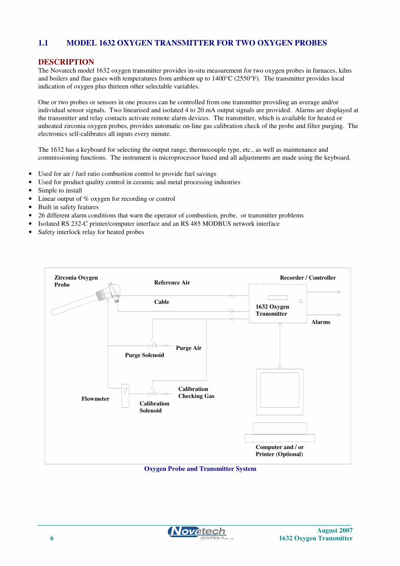
1.1 MODEL 1632 OXYGEN TRANSMITTER FOR TWO OXYGEN PROBES
DESCRIPTION The Novatech model 1632 oxygen transmitter provides in-situ measurement for two oxygen probes in furnaces, kilns
and boilers and flue gases with temperatures from ambient up to 1400°C (2550°F). The transmitter provides local
indication of oxygen plus thirteen other selectable variables.
One or two probes or sensors in one process can be controlled from one transmitter providing an average and/or
individual sensor signals. Two linearised and isolated 4 to 20 mA output signals are provided. Alarms are displayed at
the transmitter and relay contacts activate remote alarm devices. The transmitter, which is available for heated or
unheated zirconia oxygen probes, provides automatic on-line gas calibration check of the probe and filter purging. The
electronics self-calibrates all inputs every minute.
The 1632 has a keyboard for selecting the output range, thermocouple type, etc., as well as maintenance and
commissioning functions. The instrument is microprocessor based and all adjustments are made using the keyboard.
• Used for air / fuel ratio combustion control to provide fuel savings
• Used for product quality control in ceramic and metal processing industries
• Simple to install
• Linear output of % oxygen for recording or control
• Built in safety features
• 26 different alarm conditions that warn the operator of combustion, probe, or transmitter problems
• Isolated RS 232-C printer/computer interface and an RS 485 MODBUS network interface
• Safety interlock relay for heated probes
Oxygen Probe and Transmitter System
REF
1632 Oxygen
Transmitter
Computer and / or
Printer (Optional)
Reference Air
Purge Air
Flowmeter
Calibration
Checking Gas Calibration
Solenoid
Purge Solenoid
Zirconia Oxygen
Probe
Recorder / Controller
Alarms
Cable

August 2007
1632 Oxygen Transmitter 7
SPECIFICATIONS
Inputs
• Zirconia oxygen probe, heated or unheated
• Furnace, kiln or flue thermocouple, field selectable as type K or R.
• Main flame established safety interlock (for heated probes only)
• Purge pressure switch
• Dual Fuel selector
• Remote alarm accept
Outputs
• Two linearised 4 to 20 mA DC outputs, max. load 1000Ω
• Common alarm relay
• Three other alarm relays with selectable functions
Computer
• RS 232-C or RS 485 for connection of a computer terminal or printer for diagnostics of the transmitter, probe, sensor
or combustion process. This connection is suitable for network connection to computers, DCSs or PLCs using
MODBUS protocol.
Range of Output 1
Field selectable from the following:
Output Selection Range
Linear, Probe 1 0 to 1% oxygen to 0 to 100 % oxygen
Linear, Probe 1 and 2 averaged 0 to 1% oxygen to 0 to 100 % oxygen
(If 2 probes are used)
Log 0.1 to 20 % oxygen, fixed
Reducing 100 % to 10-4 oxygen, fixed
Reducing 10-1 to 10-25 % oxygen, fixed
Linear, probe 1, very low range 0 to 0.001% to 0 to 2.0 % oxygen (10ppm to 20,000ppm)
Range of Output 2
Field selectable from the following:
Output Zero Range Span Range
Sensor EMF 0 to 1100 mV in 100 mV steps 1000 to 1300 mV in 100
mV steps
Carbon Dioxide 0 to 10 % 2 to 20 %
Oxygen Deficiency 0 to 20% O2 deficiency 0 to 100% O2 excess
Aux Temperature 0 to 100°C (32 to 210°F) in 1 degree steps 100 to 1400°C (210 to
2550°F) in 100 degree
steps
Log Oxygen 0.1% O2 Fixed 20% O2 Fixed
Reducing Oxygen 10+2 (100%) to 10-10 % oxygen in one 10-3 to 10-30 % oxygen in
decade steps, non-overlapping one decade steps. Min
span two decades.
Linear Oxygen, probe 2 0% oxygen, fixed 1 to 100%
Combustibles %, Probe 1 0% combustibles fixed 0.5 to 2.0 %
Linear, Probe 1 and 2 averaged 0% oxygen, fixed 1 to 100%
(If 2 probes are used)
Range of Indication, Upper Line
• Auto ranging from 10-30 to 100% 02
Indication Choice, Lower Line
Any or all of the following can be selected for lower line display:
• Date - time
• Run Hours since last service
• Date of last service
• Probe 1 oxygen

August 2007
8 1632 Oxygen Transmitter
• Probe 2 oxygen
• Probe 1 EMF
• Probe 2 EMF
• Probe 1 Temperature
• Auxiliary Temperature
• Probe 2 Temperature
• Probe 1 Impedance
• Probe 2 Impedance
• Ambient Temperature
• Ambient Relative Humidity
• Carbon Dioxide
• Combustibles
• Oxygen Deficiency
The oxygen deficiency output can be used in the same way as a combustibles transmitter to signal the extent of reducing
conditions of combustion processes.
Accuracy
• ±1% of actual measured oxygen value with a repeatability of ±0.5% of measured value.
Relay Contacts
• 0.5A 24 VAC, 1A 36 VDC
Environmental Rating
• Operating Temperature: -25 to 55°C (-15 to 130°F)
• Relative Humidity: 5 to 95% (non-condensing)
• Vibration: 10 to 150Hz (2g peak)
Power Requirements
• 240 or 110V, 50/60 Hz, 105 VA (heated probe)
• 240 or 110V, 50/60 Hz, 5 VA (unheated probe)
Weight
• Transmitter, 3.75 kg (10 lbs.)
Dimensions
• 280mm (11”) W x 180mm (7”) H x 95mm (3.75”) D
Degree of Protection
• IP65 without reference air pump
• IP54 with reference air pump
Mounting
• Suitable for wall or surface mounting.
August 2007
1632 Oxygen Transmitter 9
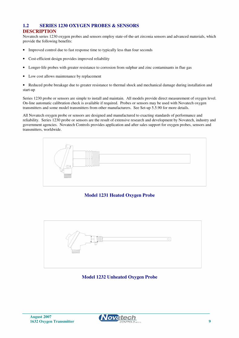
1.2 SERIES 1230 OXYGEN PROBES & SENSORS
DESCRIPTION Novatech series 1230 oxygen probes and sensors employ state-of-the-art zirconia sensors and advanced materials, which
provide the following benefits:
• Improved control due to fast response time to typically less than four seconds
• Cost-efficient design provides improved reliability
• Longer-life probes with greater resistance to corrosion from sulphur and zinc contaminants in flue gas
• Low cost allows maintenance by replacement
• Reduced probe breakage due to greater resistance to thermal shock and mechanical damage during installation and
start-up
Series 1230 probe or sensors are simple to install and maintain. All models provide direct measurement of oxygen level.
On-line automatic calibration check is available if required. Probes or sensors may be used with Novatech oxygen
transmitters and some model transmitters from other manufacturers. See Set-up 5.5.90 for more details.
All Novatech oxygen probe or sensors are designed and manufactured to exacting standards of performance and
reliability. Series 1230 probe or sensors are the result of extensive research and development by Novatech, industry and
government agencies. Novatech Controls provides application and after sales support for oxygen probes, sensors and
transmitters, worldwide.
Model 1231 Heated Oxygen Probe
Model 1232 Unheated Oxygen Probe
REF
August 2007
10 1632 Oxygen Transmitter
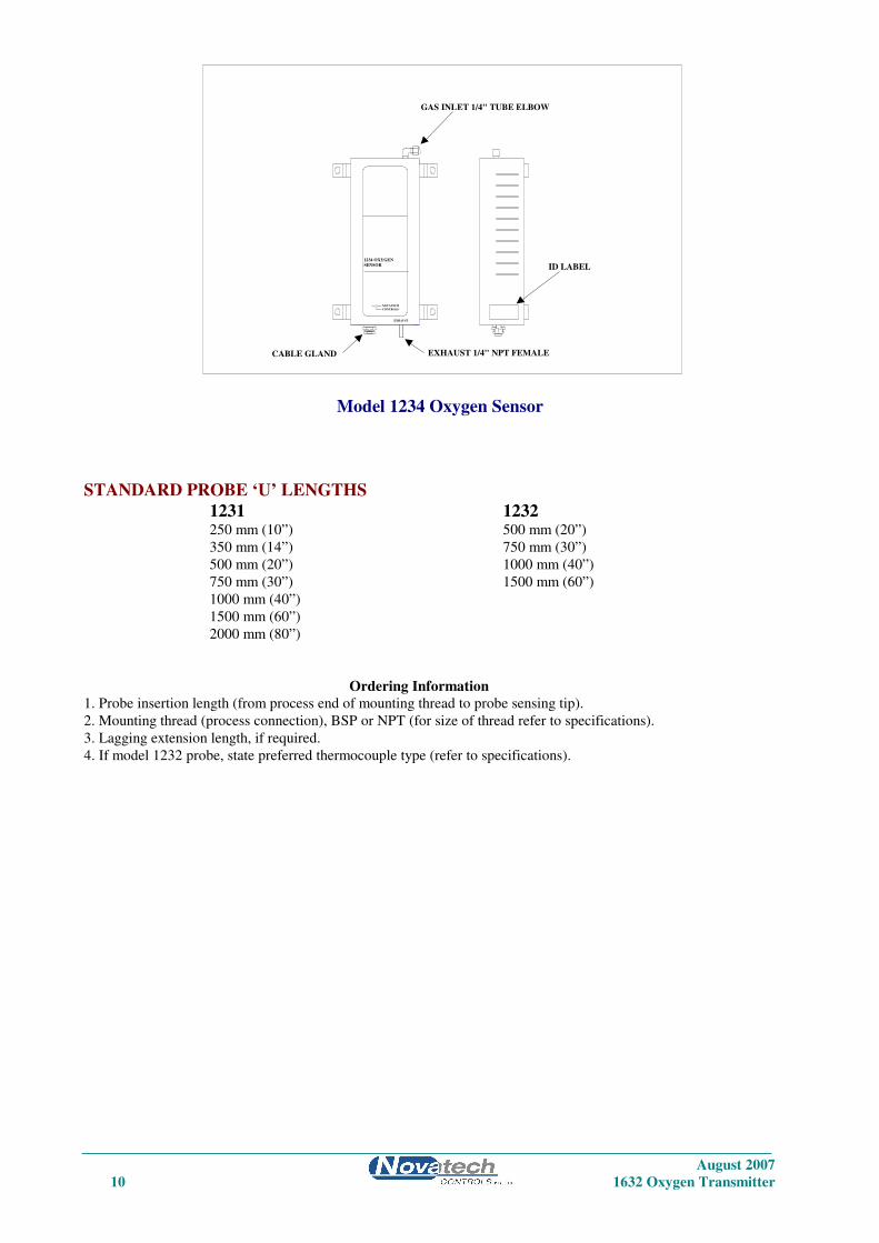
Model 1234 Oxygen Sensor
STANDARD PROBE ‘U’ LENGTHS
1231 1232 250 mm (10”) 500 mm (20”)
350 mm (14”) 750 mm (30”)
500 mm (20”) 1000 mm (40”)
750 mm (30”) 1500 mm (60”)
1000 mm (40”)
1500 mm (60”)
2000 mm (80”)
Ordering Information
1. Probe insertion length (from process end of mounting thread to probe sensing tip).
2. Mounting thread (process connection), BSP or NPT (for size of thread refer to specifications).
3. Lagging extension length, if required.
4. If model 1232 probe, state preferred thermocouple type (refer to specifications).
EXHAUST
1234 OXYGEN
SENSOR
NOVATECH
CONTROLS
CABLE GLAND
ID LABEL
EXHAUST 1/4" NPT FEMALE
GAS INLET 1/4" TUBE ELBOW

August 2007
1632 Oxygen Transmitter 11
Important Notice Regarding
1231 Probe Option - FIL-3
WARNING: The only identifiable standard for flame arresters for general use is British Standard BS EN 12874:2001.
British Standard BS EN 12874:2001 refers to an operating environment up to 150 Degrees Centigrade.
The FIL-3 device optionally fitted to 1231 Heated Zirconia Probes (the “Probes" or "Probe") operate in an environment
considerably greater than 150 Degrees Centigrade.
Therefore, we know of no Australian, British, European or USA standard applicable to flame arresters or their testing
above 150 degrees Centigrade. Consequently, the FIL-3 device cannot be certified as a safety device.
The probe is only one of several potential sources of ignition. Extreme care is required when using the probes during
the start up processes of a combustion appliance.
The Novatech Burner Interlock Relay facility, which is a standard part of the Novatech transmitter, is designed to be
wired to the main safety shut-off fuel valves in a way that can shutdown the probe heater when the fuel valves are
closed.
The risk of ignition of flammable gas mixture at the hot end of the Probe can only be minimised by correct use,
maintenance and operation of the FIL-3 device. The user of the FIL-3 device is responsible for verification and
maintenance and correct use and operation of the FIL-3 device.
THE USER AGREES THAT IT USES THE PROBE AND THE FIL-3 DEVICE AT ITS SOLE RISK. NOVATECH
CONTROLS PTY LTD, TO THE FULL EXTENT PERMITTED BY LAW, GIVES NO WARRANTIES OR
ASSURANCES AND EXCLUDES ALL LIABILITY (INCLUDING LIABILITY FOR NEGLIGENCE) IN
RELATION TO THE PROBE AND THE FIL-3 DEVICE.
The user must ensure that it correctly follows all instructions in relation to the Probe and FIL-3 device, correctly
understands the specifications of the Probe and FIL-3 device and ensures that the Probe and FIL-3 device are regularly
inspected and maintained.
FIL-3 equipped Probes should be inspected at least once a year for corrosion and more frequently if there is any reason
to suspect that corrosion may have occurred.
August 2007
12 1632 Oxygen Transmitter
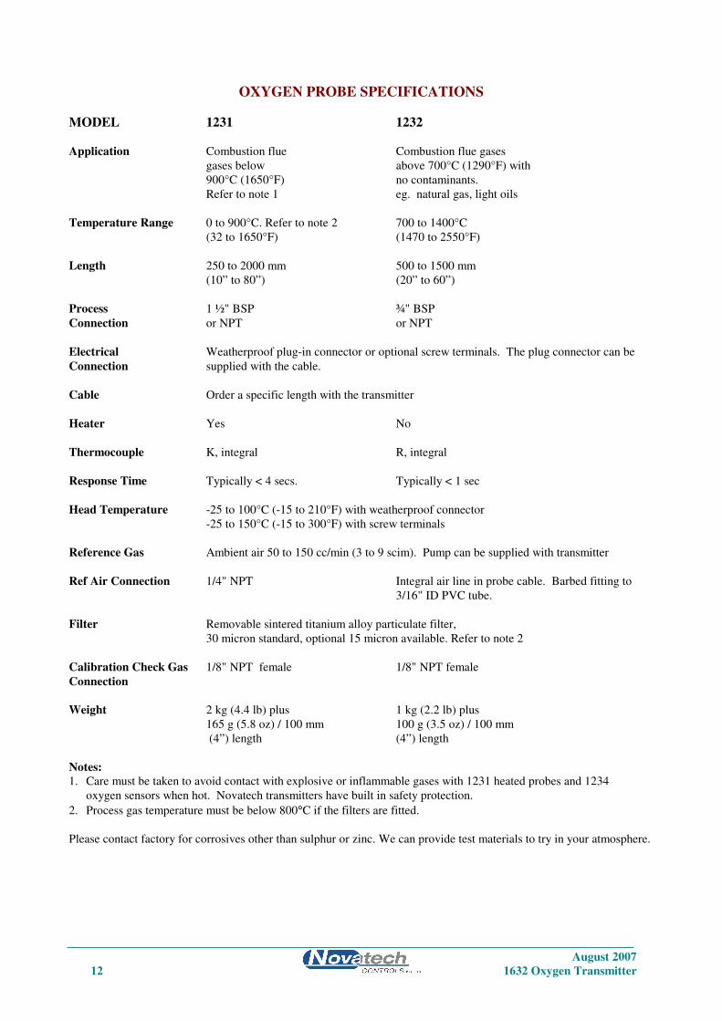
OXYGEN PROBE SPECIFICATIONS
MODEL 1231 1232
Application Combustion flue Combustion flue gases
gases below above 700°C (1290°F) with
900°C (1650°F) no contaminants.
Refer to note 1 eg. natural gas, light oils
Temperature Range 0 to 900°C. Refer to note 2 700 to 1400°C
(32 to 1650°F) (1470 to 2550°F)
Length 250 to 2000 mm 500 to 1500 mm
(10” to 80”) (20” to 60”)
Process 1 ½" BSP ¾" BSP
Connection or NPT or NPT
Electrical Weatherproof plug-in connector or optional screw terminals. The plug connector can be
Connection supplied with the cable.
Cable Order a specific length with the transmitter
Heater Yes No
Thermocouple K, integral R, integral
Response Time Typically < 4 secs. Typically < 1 sec
Head Temperature -25 to 100°C (-15 to 210°F) with weatherproof connector
-25 to 150°C (-15 to 300°F) with screw terminals
Reference Gas Ambient air 50 to 150 cc/min (3 to 9 scim). Pump can be supplied with transmitter
Ref Air Connection 1/4" NPT Integral air line in probe cable. Barbed fitting to
3/16" ID PVC tube.
Filter Removable sintered titanium alloy particulate filter,
30 micron standard, optional 15 micron available. Refer to note 2
Calibration Check Gas 1/8" NPT female 1/8" NPT female
Connection
Weight 2 kg (4.4 lb) plus 1 kg (2.2 lb) plus
165 g (5.8 oz) / 100 mm 100 g (3.5 oz) / 100 mm
(4”) length (4”) length
Notes:
1. Care must be taken to avoid contact with explosive or inflammable gases with 1231 heated probes and 1234
oxygen sensors when hot. Novatech transmitters have built in safety protection.
2. Process gas temperature must be below 800°C if the filters are fitted.
Please contact factory for corrosives other than sulphur or zinc. We can provide test materials to try in your atmosphere.

August 2007
1632 Oxygen Transmitter 13
OXYGEN PROBE MODEL SELECTION GUIDE
Heated probes-temperature range 0-900°C (1650°F).
1231 - U Length - Outer - Internal - Mounting
Sheath Thermocouple Thread
Basic model 2. 250mm (10”) 1. 316 SS max 850°C 1. Type K max 900°C 1. 1 ½ BSP
3. 500mm (20”) (1560°F) (1650°F) 2. 1 ½ NPT
4. 750mm (30”) 2. Inconel *(1)
5. 1000mm (40”)
6. 1500mm (60”)
7. 2000mm (80”)
*Note: (1) The Inconel option has all inconel wetted parts except for the ceramic sensor and viton ‘o’ rings.
Unheated probes for clean gases-temperature range 700-1400°C (1290-2550°F).
1232 - U Length - Outer Sheath - Internal Thermocouple - Mounting Thread
Basic model 3. 500mm (20”) 1. 253 MA-max 1000°C 1. Nil *(2) 1. 3/4” BSP fixed
4. 750mm (30”) (1830°F) 4. Type R max 1400°C 2. 3/4” NPT fixed
5. 1000mm (40”) (2550°F)
6. 1500mm (60”) 3. High Purity Alumina
max 1300°C (2370°F) Horizontal
max 1400°C (2550°F) Vertical
4. 446 SS max 1000°C (1830°F)
*Note: (2) A standard oxygen probe for carburising furnaces, has a 253 MA sheath.
1234 SENSOR SPECIFICATIONS
Range of measurement: 1 ppm to 100% oxygen
Output: EMF = 2.154.10-2
.T.loge (0.209/oxygen level of the sample)
Accuracy: ± 1%
Thermocouple: Type K
Heater: 110 VAC 50 / 60Hz, 100 watts
Heater proportional band: 80°C (175°F)
Speed of Response: Less than 100 milliseconds
Sample flow rate: 1 to 5 litres / minute (120 to 600 scfm)
Differential Pressure: 80 to 800 mm (3 to 30”) WG gives a flow of 1 to 5 litres / min (120 to 600 scfm)
Process Connections: 1/4” NPT female, inlet and outlet
Dimensions: 300 mm (11.81”) high by 125 mm (4.92”) wide by 88 mm (3.46”) deep
Weight: 2.1 kg (4.6 lb)

August 2007
14 1632 Oxygen Transmitter
1.3 PURGE & CALIBRATION CHECK ACCESSORIES Due to the absolute measurement characteristics of zirconia sensors and the self-calibration features of Novatech
transmitters, probe calibration checks with calibrated gas are not normally required. In some installations however,
automatic gas calibration checks are required by Environmental Protection Authorities and by engineering management
in Power Stations, Oil Refineries and similar large end users.
Novatech probes and transmitters provide a ready method of connecting on-line calibration check gases. They provide
on-line automatic checking of probe and transmitter calibration, as well as a probe purge facility.
The absolute characteristics of zirconia sensors require only one calibration check gas to properly check the probe’s
performance. Where required however, the dual gas calibration check facility can be utilised.
Dirty flue gas applications often require the back purge facility to keep a probe filter free from blockage. (In these
applications, it is more reliable to install probes pointing vertically downwards with no filter). Purge and calibration
check solenoid valves can be operated manually or automatically from a 1632 transmitter.
The external components required for automatic / manual gas calibration checking are:
• A calibration check gas flow meter/regulator
• A mains voltage (240 or 110 VAC) solenoid valve for each calibration check gas
The external components required for automatic / manual purging are:
• A mains voltage (240 or 110 VAC) purge solenoid valve
• A purge pressure switch, 0 to 35 kPa (0 to 5 psi), to test for filter blockage.
The user should supply:
• Span gas cylinder(s), typically 2 % oxygen in nitrogen or a similar percentage of 02 close to the normal level in the
gas stream being measured, to ensure fast recovery.
• A 100 kPa (15 psi) clean and dry instrument air supply when filter purging is required.
1.4 FILTER PURGE PRESSURE SWITCH To automatically sense a blocked probe filter, a pressure sensor should be connected to the ‘purge’ line to the probe
‘cal’ port. It should be adjusted so that it energises just above the purge pressure with a new or clean filter installed.
The switch contacts should be connected to terminals 12 & 13 (PURGE FL SWITCH).
If the filter is still blocked or partly blocked after an auto purge cycle, the pressure switch will energise and cause a
‘Probe Filter Blocked’ alarm. The contacts must be normally closed.
The pressure switch should have an adjustable range of 0 to 100 kPa (0 to 15 psi).

August 2007
1632 Oxygen Transmitter 15
DESCRIPTION
2
SECTION
NUMBER
2.1 THE ZIRCONIA SENSOR
2.2 THE OXYGEN PROBE OR SENSOR
2.3 THE TRANSMITTER
2.4 ALARMS
2.5 HEATER
2.6 APPLICATIONS WHERE SENSING POINT
IS NOT AT ATMOSPHERIC PRESSURE
2.7 SENSOR IMPEDANCE
2.8 AUTO CALIBRATION—ELECTRONICS
2.9 MANUAL CALIBRATION—PROBES
2.10 AUTO CALIBRATION CHECKING—PROBES
2.11 AUTO PURGE
2.12 RS 485 NETWORK (MODBUS™) AND 232-C PORT
2.13 AUXILIARY TEMPERATURE THERMOCOUPLE
2.14 WATCHDOG TIMER
2.15 BACK UP BATTERY
August 2007
16 1632 Oxygen Transmitter
DESCRIPTION
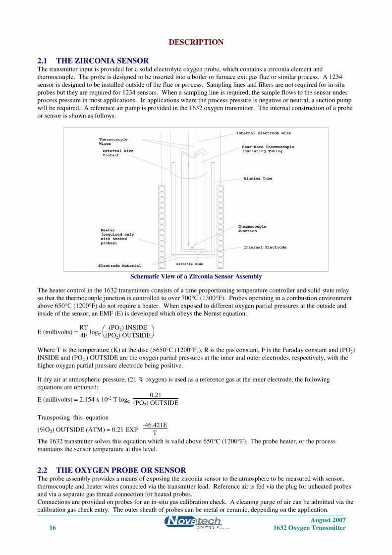
2.1 THE ZIRCONIA SENSOR The transmitter input is provided for a solid electrolyte oxygen probe, which contains a zirconia element and
thermocouple. The probe is designed to be inserted into a boiler or furnace exit gas flue or similar process. A 1234
sensor is designed to be installed outside of the flue or process. Sampling lines and filters are not required for in-situ
probes but they are required for 1234 sensors. When a sampling line is required, the sample flows to the sensor under
process pressure in most applications. In applications where the process pressure is negative or neutral, a suction pump
will be required. A reference air pump is provided in the 1632 oxygen transmitter. The internal construction of a probe
or sensor is shown as follows.
Internal electrode wire
Zirconia Disc
Thermocouple
Wires
Electrode Material
(required only
Heater
with heated
probes)
External Wire
Contact
Thermocouple
Junction
Internal Electrode
Four-Bore Thermocouple
Insulating Tubing
Alumina Tube
Schematic View of a Zirconia Sensor Assembly
The heater control in the 1632 transmitters consists of a time proportioning temperature controller and solid state relay
so that the thermocouple junction is controlled to over 700°C (1300°F). Probes operating in a combustion environment
above 650°C (1200°F) do not require a heater. When exposed to different oxygen partial pressures at the outside and
inside of the sensor, an EMF (E) is developed which obeys the Nernst equation:
E (millivolts) = RT
4F loge
(PO2) INSIDE
(PO2) OUTSIDE
Where T is the temperature (K) at the disc (>650°C (1200°F)), R is the gas constant, F is the Faraday constant and (PO2)
INSIDE and (PO2 ) OUTSIDE are the oxygen partial pressures at the inner and outer electrodes, respectively, with the
higher oxygen partial pressure electrode being positive.
If dry air at atmospheric pressure, (21 % oxygen) is used as a reference gas at the inner electrode, the following
equations are obtained:
E (millivolts) = 2.154 x 10⁻² T loge 0.21
(PO2) OUTSIDE
Transposing this equation
(%O2) OUTSIDE (ATM) = 0.21 EXP -46.421E
T
The 1632 transmitter solves this equation which is valid above 650°C (1200°F). The probe heater, or the process
maintains the sensor temperature at this level.
2.2 THE OXYGEN PROBE OR SENSOR The probe assembly provides a means of exposing the zirconia sensor to the atmosphere to be measured with sensor,
thermocouple and heater wires connected via the transmitter lead. Reference air is fed via the plug for unheated probes
and via a separate gas thread connection for heated probes.
Connections are provided on probes for an in-situ gas calibration check. A cleaning purge of air can be admitted via the
calibration gas check entry. The outer sheath of probes can be metal or ceramic, depending on the application.

August 2007
1632 Oxygen Transmitter 17
Calibration check can be achieved on 1234 sensors using a three way solenoid which blocks the sample and at the same
time admits a calibration check gas to the sensor. Purging a probe for any dust build up can be achieved in the same
way.
In-situ zirconia oxygen probes will give a lower oxygen reading than a sampled gas measurement on a chromatograph or
paramagnetic transmitter because the flue gas contains a significant level of water vapour and a sampling system
removes the water vapour through condensation. The oxygen content then appears as a higher percentage of the
remaining gas. For example: If the gas contained five parts oxygen and fifteen parts moisture, removing the moisture
would leave the oxygen at 5.88%. This phenomena will depend on the fuel and the completeness of combustion. They
are common to all in-situ oxygen sensors.
2.3 THE TRANSMITTER The top line of the transmitter display will read oxygen in either % or ppm.
The 1632 transmitter is a transmitter with two 4 to 20 mA outputs. One output is linear oxygen with selectable span.
The second output can be selected as oxygen deficiency, combustibles, auxiliary temperature, reducing oxygen, percent
carbon dioxide, sensor EMF or a logarithmic oxygen range. Four alarm relays are provided. Refer to the sections 4.2
and 4.3 for more details.
The 1632 transmitter is designed to operate with either one or two heated or unheated, zirconia probes or sensors in one
process. If two sensors are being used, the transmitter can average the two oxygen signals, alarm when there is a high
difference, transmit and display the average and/or individual oxygen signals.
If heated probes are being used, the transmitter will maintain the temperature of the sensor(s) to over 700°C (1300°F).
If the flue gas temperature is above 850°C (1560°F), the probe heater will cut out completely and the process will
provide probe heating. The transmitter solves the Nernst equation and will provide accurate oxygen measurements up to
1500°C (2730°F), although most probes are suitable only to 1400°C (2250°F). 1231 heated probes are limited to 900°C
(1650°F).
2.4 ALARMS Refer to OPERATOR FUNCTIONS Section 4 for details on alarm functions.
2.5 HEATER
CAUTION The probe or sensor heater is supplied with mains voltage. This supply has electrical shock danger to maintenance
personnel. Always isolate the transmitter before working with the probe or sensor.
The EARTH wire (green) from the probe/sensor must always be connected to earth.
The heater is supplied from the mains power directly, and the temperature is controlled initially at over 700°C (1300°F)
after turn on.
2.6 APPLICATIONS WHERE SENSING POINT IS NOT AT ATMOSPHERIC
PRESSURE To apply the 1632 transmitter to processes that have pressure at the point of measurement significantly above or below
atmospheric pressure, then compensation must be applied. (Refer to Set-up Steps 37 and 38 in Section 5.5). If two
probes are being used, they must be close to the same pressure.
If the process pressure is not constant, it can be measured by a pressure transducer and fed into the oxygen transmitter as
a 4-20mA signal. The pressure compensation will then change the oxygen reading according to the current process
pressure.
2.7 SENSOR IMPEDANCE The zirconia sensor impedance is a basic measurement of the reliability of the oxygen reading. A probe or sensor with a
high impedance reading will eventually produce erroneous signals. The transmitter checks the zirconia sensor
impedance every 24 hours and if the impedance is above the maximum level for a specific temperature then the
impedance alarm (Sensor Fail) will be activated. Typical sensor impedance is 1 KΩ to 8 KΩ at 720°C (1320°F).
The impedance measurement can be updated manually whenever the sensor is over 700°C (1290°F) by pressing the
“AUTOCAL” button while in “RUN” mode. The “Z” will appear in the top RH corner of the display for 3 seconds to
confirm the measurement.

August 2007
18 1632 Oxygen Transmitter
2.8 AUTO CALIBRATION - ELECTRONICS The transmitter input section is self-calibrating. There are no adjustments. The analog to digital converter input stages
are checked against a precision reference source and calibrated once every three seconds. Should the input electronics
drift slightly then the drift will be automatically compensated for within the microprocessor. If the calibration factors
are found to be have been changed more than expected, an ‘ADC Warning’ alarm is generated. If a large error occurs
due to an electronic fault then an ‘ADC CAL FAIL’ alarm will occur.
A one-off calibration procedure of the precision reference sources should never need to be repeated for the instrument
life unless the instrument has been repaired. For a description of the calibration procedure, refer to ‘Setting Up The
transmitter’ Section 5.5, items 7, 8 9 and 10.
The digital to analog converters or output section of the transmitter are tested for accuracy when the ‘AUTOCAL’
button is pressed, and when the transmitter goes through the start up procedure. If the output calibration factors are
found to have changed more than expected, the ‘DAC Warning’ alarm will occur. If either output has a fault, the ‘DAC
CAL FAIL’ alarm will occur. The D/A sections are re-calibrated by pressing the ‘AUTO CAL’ button on the keyboard
while in 'SET-UP' mode. Each of the output channels have three menu items which provide manual calibration (set-up
13 to 18). If manual is selected in set-up 13 or 16, the ‘AUTO CAL’ will be skipped and the manual calibration factors
will be retained. See section 5.5 set-up 13, and section 6.3 for more details.
All output signals will drop to 0 mA for one-second period. It is suggested that a D/A re-calibration be performed after
the instrument has stabilised, approximately 30 minutes after first switching on and after Setting Up The transmitter
Section 5.5, items 6, 7, 8 and 9 have been completed, and then annually.
2.9 MANUAL CALIBRATION - PROBES Calibration of the probe generally only requires the Sensor Offset to be set. See Section 5.5.11 for more details.
If the offset for a sensor is not set the error will generally be less than 5% of the actual oxygen reading. By setting the
offset the error will be less than 1% of the oxygen actual reading.
If a probe made by a manufacturer other than Novatech Controls is used on the Novatech transmitter, and/or improved
accuracy is required at process levels of oxygen (well away from 20.9%) the “Low Oxygen Calibration” trim factors can
be entered. (See also Section 5.5.90)
To manually set the “Low Oxygen Calibration” first set the Sensor Offset, then the “Low Oxygen Calibration”.
1. To check a probe offset on site, the probe must be sensing air, with reference air, and allowed to settle at the probe
operating temperature for 30 minutes. Read the offset in ‘RUN’ mode in millivolts on the lower line. Offset errors can
occur if the sensor does not have some air passing over it. A gentle flow (<0.5 l/min) of air in the calibration check port
can be provided by a reference air pump or similar.
The best results will be obtained if the probe is removed from the process.
For heated probes, if the combustion appliance is not operational and the probe heater is interlocked with the ‘BURNER
ON’ signal, the ‘BURNER BYPASS’ switch should be set to ‘ON to power the probe heater after removing the probe
from the flue.
CAUTION DANGER
Return the ‘BURNER BYPASS’ switch to normal (off) before installing the probe in the flue.
For unheated probes, the probe sensing tip must be raised to at least 650°C (1200°F) with a portable furnace.
Determine the probe offset in ‘RUN’ mode. Select ‘Sensor EMF’ on the lower line. With probe in air, stabilised at
temperature for 30 minutes, read the ‘Sensor EMF’. Switch back to ‘set-up’ mode and enter ‘Sensor Offset’ of equal
value and the same polarity.
eg. If the measured ’SENSOR OFFSET’ was -1.2 mV, enter -1.2 mV.
When reading the EMF offset, the flue pressure compensation must be set. If the probe has been removed from the flue,
set the flue pressure compensation set up to “Fixed” in set-up 34, and the value to 0 in set-up step 38.
2. To set the probe “Low Oxygen Calibration”, replace the air purge in the calibration check port with a flow of gas
from a certified gas bottle. A flow of <1 l/min should be used. After purging for 1 minute compare the oxygen reading
to the oxygen concentration on the bottle certificate. If the transmitter is reading lower than the certified level, switch to
August 2007
1632 Oxygen Transmitter 19
the ‘set-up’ mode and raise the figure set-up 90 (for sensor 1). An increase of 1% in the set-up entry will increase the
oxygen reading by about 3% of the actual oxygen reading.
NOTE: If the set-up items 90 and 91 are not available, see section 5.1.
It is very unusual to need to change the settings by more than 1%. If a setting of more than 1% seems
necessary, check for gas leaks, reference air flow or excess calibration gas flow.
2.10 AUTO CALIBRATION CHECKING - PROBES On-line automatic gas calibration check is not normally required. Where it is required however, the probe can be
checked for accuracy in-situ and on-line. Solenoid valves can admit up to two calibrated gas mixtures into the probe via
solenoid valves under microprocessor control on a timed basis. For details on installation refer Section 3.11. For details
on setting up this facility refer to Set-up steps 57 to 69 in Section 5.5.
During probe auto calibration checking, the transmitter output will freeze and remain frozen for a further adjustable
period, allowing the probe time to recover and continue reading the flue gas oxygen level.
Calibration check gases may be manually admitted by pressing the ‘CAL’ buttons on the keyboard while in ‘RUN’
mode. The transmitter output is frozen during the pressing of these buttons and immediately becomes active when the
button is released. If calibration gas checking is enabled in the Set-up menu for either gas, an automatic gas cycle can
be started by pressing the ‘CAL’ buttons in RUN mode. Pressing any other button can terminate the cycle.
2.11 AUTO PURGE In oil and coal fired plants, it is possible for the probe sensing filter to become blocked. An automatic purge cycle can
be set up so that a blast of air, maximum 100 kPa (14.5 psi), will automatically back-flush the probe filter on a timed
basis. Refer to Set-up steps 52 to 56 in Section 5.5. A purge pressure switch will sense if there is insufficient flow to
clear the filter during the purge cycle. In this case a ‘PROBE FILTER’ alarm will occur. The probe can be manually
purged from the keyboard while in ‘RUN’ mode. The transmitter output is not frozen during or after the pressing of this
button.
If two probes are being used, the two probes could be driven by a common solenoid but separate pressure regulators and
pressure switches (See section 3.11)
2.12 RS 485 NETWORK (MODBUS) AND RS 232C PORT The serial port has two functions. -
It can be configured to connect up to 31 transmitters together on a MODBUS™ RS485 network.
Each individual transmitter can be interrogated by a computer or PLC. The values of oxygen, sensor EMF, sensor
temperature, sensor impedance for both oxygen sensors (if two sensors are being used on one transmitter) can be read
over the network. The alarms status can also be checked over the network.
For the connection details, see Section 3.15 and Appendix 6.
It can be used to log the transmitter readings by connecting the transmitter to a printer, a data logger, or any
computer using an RS232-C com port.
When it is to be used to log the transmitter readings, use set-up step 82 to selected the items to be sent to the data logger.
The log period may be selected in set-up step 83, and the baud rate may be set in set-up step 84. Alarms, including the
time they occurred, will be transmitted to the printer and computer whenever they are first initiated, accepted and
cleared. The protocol for the serial port is eight data bits, one stop bit, no parity.
2.13 AUXILIARY TEMPERATURE THERMOCOUPLE A flue thermocouple must be connected to the AUX thermocouple input when combustibles display is required.
The AUX thermocouple may also be used to monitor and display any process temperature.

August 2007
20 1632 Oxygen Transmitter
2.14 WATCHDOG TIMER The watchdog timer is started if the microprocessor fails to pulse it within any one-second period, (ie. fails to run its
normal program). The microprocessor will then be reset up to three times until normal operation is resumed. Reset
cycles are displayed by the POWER light on the keyboard. A steady ‘ON’ light indicates normal operation. If the
program has not resumed normal operation after three attempts to reset, the common alarm relay will be activated. The
reset function will continue repeatedly after the alarm. If a successful reset is achieved, the alarm will be cancelled and
the transmitter will continue to run normally.
2.15 BACK-UP BATTERY The transmitter’s RAM and real-time clock are backed up by a lithium battery in the event of power failure. All set-up
variables are saved and the clock is kept running for approximately ten years with the power off. The battery module
should be replaced every 8 years. (It is the battery shaped device clipped in a socket labelled M1.)

August 2007
1632 Oxygen Transmitter 21
INSTALLING &
COMMISSIONING
3
SECTION
NUMBER INSTALLATION
3.1 MOUNTING THE TRANSMITTER
3.2a INSTALLING AN OXYGEN PROBE
3.2b INSTALLING A 1234 OXYGEN SENSOR
3.3 INSTALLING THE AUXILIARY THERMOCOUPLE
3.4 SHIELD CONNECTIONS
3.5 ELECTRICAL CONNECTIONS
3.6 HEATER INTERLOCK RELAYS
3.7a CONNECTING AN OXYGEN PROBE CABLE
3.7b CONNECTING A 1234 SENSOR CABLE
3.8 CONNECTING THE AUXILIARY THERMOCOUPLE (OPTIONAL)
3.9 CONNECTING THE OUTPUT CHANNELS
3.10 CONNECTING THE ALARMS
3.11 CONNECTING THE AUTOMATIC PURGE & CALIBRATION CHECK SYSTEM
3.12 CONNECTING REFERENCE AIR
3.13 CONNECTING THE DUAL FUEL INPUT
3.14 CONNECTING THE PRINTER
3.15 CONNECTING THE TRANSMITTER TO A MODBUS™ NETWORK
COMMISSIONING
3.16 CONNECTING POWER
3.17 COMMISSIONING - SET-UP MODE
3.18 COMMISSIONING - RUN MODE
3.19 BURNER BY-PASS SWITCH
3.20 CHECKING ALARMS
3.21 PROBE CALIBRATION CHECK
3.22 FILTER PURGE SET-UP PROCEDURE
3.23 CALIBRATION CHECK GAS SET-UP PROCEDURE
3.24 DUST IN THE FLUE GAS
3.25 STRATIFICATION
3.26 CONNECTING A PRESSURE TRANSDUCER
August 2007
22 1632 Oxygen Transmitter
INSTALLATION
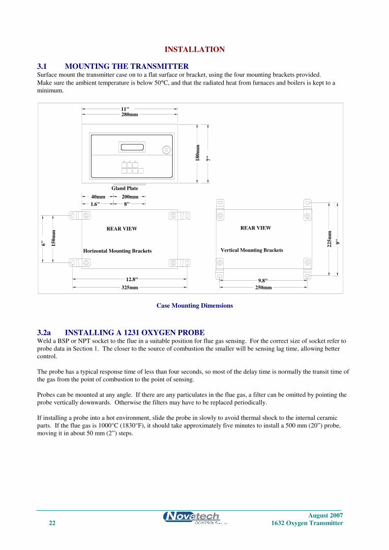
3.1 MOUNTING THE TRANSMITTER Surface mount the transmitter case on to a flat surface or bracket, using the four mounting brackets provided.
Make sure the ambient temperature is below 50°C, and that the radiated heat from furnaces and boilers is kept to a
minimum.
Case Mounting Dimensions
3.2a INSTALLING A 1231 OXYGEN PROBE Weld a BSP or NPT socket to the flue in a suitable position for flue gas sensing. For the correct size of socket refer to
probe data in Section 1. The closer to the source of combustion the smaller will be sensing lag time, allowing better
control.
The probe has a typical response time of less than four seconds, so most of the delay time is normally the transit time of
the gas from the point of combustion to the point of sensing.
Probes can be mounted at any angle. If there are any particulates in the flue gas, a filter can be omitted by pointing the
probe vertically downwards. Otherwise the filters may have to be replaced periodically.
If installing a probe into a hot environment, slide the probe in slowly to avoid thermal shock to the internal ceramic
parts. If the flue gas is 1000°C (1830°F), it should take approximately five minutes to install a 500 mm (20”) probe,
moving it in about 50 mm (2”) steps.
Gland Plate
Vertical Mounting Brackets Horizontal Mounting Brackets
15
0m
m
280mm
180
mm
22
5m
m
250mm 325mm
11"
7"
6"
12.8" 9.8"
9"
REAR VIEW
200mm 8"
40mm 1.6"
REAR VIEW

August 2007
1632 Oxygen Transmitter 23
Oxygen Probe Mounting
CAUTION
It is important that there is no air in leakage upstream of the oxygen sensing point, otherwise there will be a high oxygen
reading.
If the probe is to be installed on a bend in the flue, it is best located on the outer circumference of the bend to avoid dead
pockets of flue gas flow. While the standard 1231 probe with a ‘U’ length of 250 mm (10”) will suit most low
temperature flue applications, it is occasionally necessary to have a longer probe with the sensing tip in the center of the
flue gas stream.
Although it is rare, occasionally a probe may sense oxygen vastly differently from the average reading in the flue gas. If
it occurs, then the probe should be moved, or a longer probe installed. This phenomena is normally caused by
stratification of the flue gas.
REF
Preferred mounting angle if
there are particulates in the
flue gas and no filter is used.
RE
F
Furnace, flue
Probe may be mounted
horizontal

August 2007
24 1632 Oxygen Transmitter
3.2b INSTALLING A 1234 OXYGEN SENSOR Mounting - Screw the 1234 sensor to a wall or similar surface with the piping connections at the bottom.
1234 Sensor Mounting Dimensions
Sample Piping - Connect the gas sample piping to the “sample in” port. If the process, boiler, kiln or furnace has a
positive pressure, no suction will be required. If the sample is under a negative pressure, connect a pump to the “inlet”
port as shown below. The flow rate should be within the range of 1 to 5 litres/minute (120 to 600 scfm).
3.3 INSTALLING THE AUXILIARY THERMOCOUPLE Weld a 1/2 inch BSP mounting socket to the flue within about 300 mm (12”), and upstream of the oxygen probe. The
thermocouple should be of similar length to the oxygen probe to prevent flue temperature distribution errors.
3.4 SHIELD CONNECTIONS All external wiring to the 1632 transmitter should be shielded. Do not connect shields at the field end. Simply clip off
and insulate. An extra terminal strip may be required to connect all shields together. This should be supplied by the
installer.
Optional vent to
atmospherre
Optional return
to flue
Upward sloping
sample line 3/8”
stainless steelFlue
Gas
Flowmeter
Sampling
Probe
1234
Sensor
Vent or return
to process
Dry
Process
Gas
1/4" Stainless Steel Tube
1234
Sensor
SAMPLE IN
EXHAUST
1234 OXYGEN SENSOR
NOVATECHCONTROLS
CABLE
LABEL
EXHAUST 1/4" NPT
FEMALE
INLET 1/4" TUBE
10
"
2.7"
25
0.0
02
5.0
01"
1.2"30
.00
56.00
0.8"
20.00
173.00
6.8"

August 2007
1632 Oxygen Transmitter 25
3.5 ELECTRICAL CONNECTIONS All wiring should comply with local electrical codes. The printed circuit boards are fully floating above earth. All earth
and shield connections should be connected to the earth stud on the LHS inside the case. Before connection of mains
power check that the 115 / 230 volt power selector switch is set to the correct voltage.
Connection Diagram for 1632 Transmitter and one or two 1231 / 1234 Heated Sensors
21 RS-232 Tx
22 Network -
23
24
25
26 Output 1-
27 Output 2+
28 Output 2-
29 Common Alarm
30 Common Alarm
31 Alarm 2
32 Alarm 2
33 Alarm 3
34 Alarm 3
35 Alarm 4
36 Alarm 4
SENSOR #1
SENSOR #2
4-20mA OutputsSelectableranges
Optional AlarmRelay ContactsNormally Closed
Mains Power
Supply240/115VAC
41
42
43 Cal 1 Sol
44 Cal 1 Sol
45 Cal 2 Sol
46 Cal 2 Sol
47 Mains E
48
49 Mains N
50 Mains A
Purge Sol
Purge Sol
51 Heater #1
52 Heater #1
White
White
White
White
53 Heater #2
54 Heater #2
Network +
Serial Common
Output 1+
Burner safety lock,or if safety interlocknot required, linkterminals 18 & 19
Orange
Brown
Black
Blue
Black
Blue
Orange
Brown
Purge Flow
SwitchPurge Flow
Remote Alarm
ResetRemote Alarm
Burner On Input
Burner On Input
RS-232 Rx
Fuel 1/2
18
19
20
15
16
17
Probe #2+
Probe #2-
Fuel 1/2
RGC I/P-
12
13
14
9
10
11
Probe TC+
Probe TC-
Probe TC2/Aux+
Probe TC2/Aux-
+12V
RGC I/P+
6
7
8
3
4
5
Probe +
Probe -
1
2
August 2007
26 1632 Oxygen Transmitter
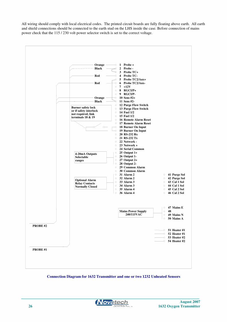
All wiring should comply with local electrical codes. The printed circuit boards are fully floating above earth. All earth
and shield connections should be connected to the earth stud on the LHS inside the case. Before connection of mains
power check that the 115 / 230 volt power selector switch is set to the correct voltage.
Connection Diagram for 1632 Transmitter and one or two 1232 Unheated Sensors
21 RS-232 Tx
22 Network -
23
24
25
26 Output 1-
27 Output 2+
28 Output 2-
29 Common Alarm
30 Common Alarm
31 Alarm 2
32 Alarm 2
33 Alarm 3
34 Alarm 3
35 Alarm 4
36 Alarm 4
PROBE #1
PROBE #2
4-20mA OutputsSelectableranges
Optional AlarmRelay ContactsNormally Closed
Mains Power Supply240/115VAC
41
42
43 Cal 1 Sol
44 Cal 1 Sol
45 Cal 2 Sol
46 Cal 2 Sol
47 Mains E
48
49 Mains N
50 Mains A
Purge Sol
Purge Sol
51 Heater #1
52 Heater #1
53 Heater #2
54 Heater #2
Network +
Serial Common
Output 1+
Burner safety lockor if safety interlocknot required, linkterminals 18 & 19
Orange
Black
Red
Red
Orange
Black
Purge Flow Switch
Purge Flow Switch
Remote Alarm Reset
Remote Alarm Reset
Burner On Input
Burner On Input
RS-232 Rx
Fuel 1/2
18
19
20
15
16
17
Sens #2+
Sens #2-
Fuel 1/2
RGCI/P-
12
13
14
9
10
11
Probe TC+
Probe TC-
Probe TC2/Aux+
Probe TC2/Aux-
+12V
RGCI/P+
6
7
8
3
4
5
Probe +
Probe -
1
2

August 2007
1632 Oxygen Transmitter 27
3.6 HEATER INTERLOCK RELAYS
CAUTION
Explosion protection for heated probes is achieved by switching the power to the probe heater off whenever the main
fuel valve is closed.
The principle of safety is that if the main fuel valve is open then main flame has been established. With this primary
source of ignition on, the probe heater can be safely switched on. The most dangerous situation is if fuel leaks into the
combustion appliance when the fuel valve is closed. When power is removed from the main fuel valve the heater should
also be switched off.
To achieve this protection, connect a main fuel valve voltage free contact to the ‘BURNER ON SWITCH’ terminals 18
& 19. When the main fuel valve is open, the voltage free contact should be closed. For installations where there is no
risk of explosion, connect a link between terminals number 18 & 19.
Heater Supply Interlock Connection for Heated Probes
If a safety interlock is not required, a wire must be connected between terminals 18 &19 to enable –
• The heaters on heated probes
• Process alarms
• Auto-purge and auto-cal checking.
3.7a CONNECTING AN OXYGEN PROBE CABLE Connect the probe lead as shown in the following drawings. Unheated probe leads have integral reference air tube. An
adaptor has been supplied to connect this tube to quarter inch flexible PVC tubing, from the air pump or reference air
supply.
Burner on Switch
For Safety Interlock
Contact must be closed when
main fuel valve is open
18
19

August 2007
28 1632 Oxygen Transmitter
B
Orange
Black1 Probe +
2 Probe -
3 Probe TC +
4 Probe TC -
ShieldCommonTerminal
OtherShields
Green &Yellow(Shield)
SensorZirconia
Red
A
ProbeThermocouple
E
C
MainsEarth
Probe HeadConnector
Note 1: Jumper terminals 3 & 4to terminals 5 & 6 if
temperature display isrequired.Use copper wire.
efficiency or flue
*Note 1
Ref Air
Reducing Fitting
1/4" PVC tube toreference air supply.
A
B
CD
E
F
G
Plug mountedon head viewedfrom outside ofhead.
(Optional)
Earth Stud
(By Installer)
Connection of Probe Cable for Unheated Probes Models 1232.
Connection of Probe Cable for Heated Probes Model 1231.
C
B
A
F
D
E
G
Orange
Black
Brown
Blue
White
White
Mains
Earth
1 Probe
2 Probe -
3 Probe TC
4 Probe TC -
Shield
Common
Terminal
(By installer)
Green
Probe
Thermocouple
Probe
Heater
Probe
Earth
Other
Shields
Probe
Head
Green &
Yellow
(Shield)
Zirconia
Sensor
Earth
Stud
51
52

August 2007
1632 Oxygen Transmitter 29
3.7b CONNECTING A 1234 SENSOR CABLE Remove the two screws from the cable gland end of the 1234 sensor. Connect the wiring as shown below. Be sure to
connect an earth to the earth stud. Replace the end plate. Tighten the cable gland onto the cable.
Connecting a 1234 Sensor Cable
3.8 CONNECTING THE AUXILIARY THERMOCOUPLE (OPTIONAL) For 1231 heated probes, the auxiliary thermocouple must be a separate TC with the junction isolated from earth,
mounted near to and upstream of the oxygen probe. It can be either a K or R type thermocouple. It is optional. If the
auxiliary temperature is not to be displayed or transmitted, then an auxiliary TC is not necessary.
3.9 CONNECTING THE OUTPUT CHANNELS The two 4 to 20 mA DC output channels are capable of driving into a 1000Ω load.
3.10 CONNECTING THE ALARMS A common alarm, which should be connected for all installations initiates on alarms functions described below. Three
additional alarm relays are available for selectable functions as listed in Section 4.2 and 4.3. Each relay has normally
closed contacts. The contacts will open in alarm condition except for the optional horn function that operates with
normally open contacts. Relays are connected as follows:
Relay Terminal Numbers
Common Alarm 29 & 30
Alarm 2 31 & 32
Alarm 3 33 & 34
Alarm 4 35 & 36
Common Alarms All of the following conditions will cause a common alarm -
ADC Calibration Fail
DAC Calibration Fail
Sensor 1 Fail
Sensor 2 Fail*
Heater 1 Fail
Heater 2 Fail*
Sensor 1 TC Open
Sensor 2 TC Open*
Aux. TC Open
Reference Air Pump Fail
Reference Air Fail **
Mains Frequency Check fail
Probe Filter Blocked
Gas 1 Calibration Check Error
Gas 2 Calibration Check Error
Burner bypass Switch on
Oxygen Deviation High*
BB RAM Fail
Watchdog Timer
* These alarms are only available if two sensors are selected
** This alarm is only available if a flow sensor is installed in CN8 on the 1630-2 PCB
The watchdog timer is a special alarm. It will force the common alarm to activate in the event of a microprocessor
failure. There will not be an alarm message displayed, but the transmitter will reset.
OXYGEN
TYPE K THERMOCOUPLE
HEATER 110VAC 100 WATTS
+
-
+
+
-
-
F BLUE
D WHITE
E WHITE
C ORANGE
B BROWN
A BLACK
August 2007
30 1632 Oxygen Transmitter
Mains Voltage 110/240 VAC
From terminals 43 & 44
Calibration Check Gas Flowmeter/Regulator
5 litres/min (10 scfh)
To Oxygen Probe
‘CAL’ port
Clean & Dry Purge
Air Supply
140 kPa max (20psi)
CAL Check Gas #1
140 kPa max (20psi)
Mains Voltage 110/240 VAC
From terminals 45 & 46
Mains Voltage 110/240 VAC
From terminals 41 & 42
CAL Check Gas #2
140 kPa max (20psi)
Mains Voltage 110/240
AC Solenoids
Cal 2 Sol 46
Purge Sol
Purge Sol
Cal 1 Sol
Cal 1 Sol
Cal 2 Sol 45
43
44
41
42
Alarms can be accepted by either pressing the alarm button (viewing the alarm messages), or by temporarily closing a
switch connected to terminals 16 & 17, REM ALARM RESET.
Alarm relay 2 to 4 Select any one or all of the following for each relay. Refer 5 to Section 5.5, steps 70 to 81
High oxygen
Low oxygen
Very low oxygen
Probe or sensor under temperature
Calibration check in progress
Probe purge in progress
Alarm horn function (Relay 4 only)
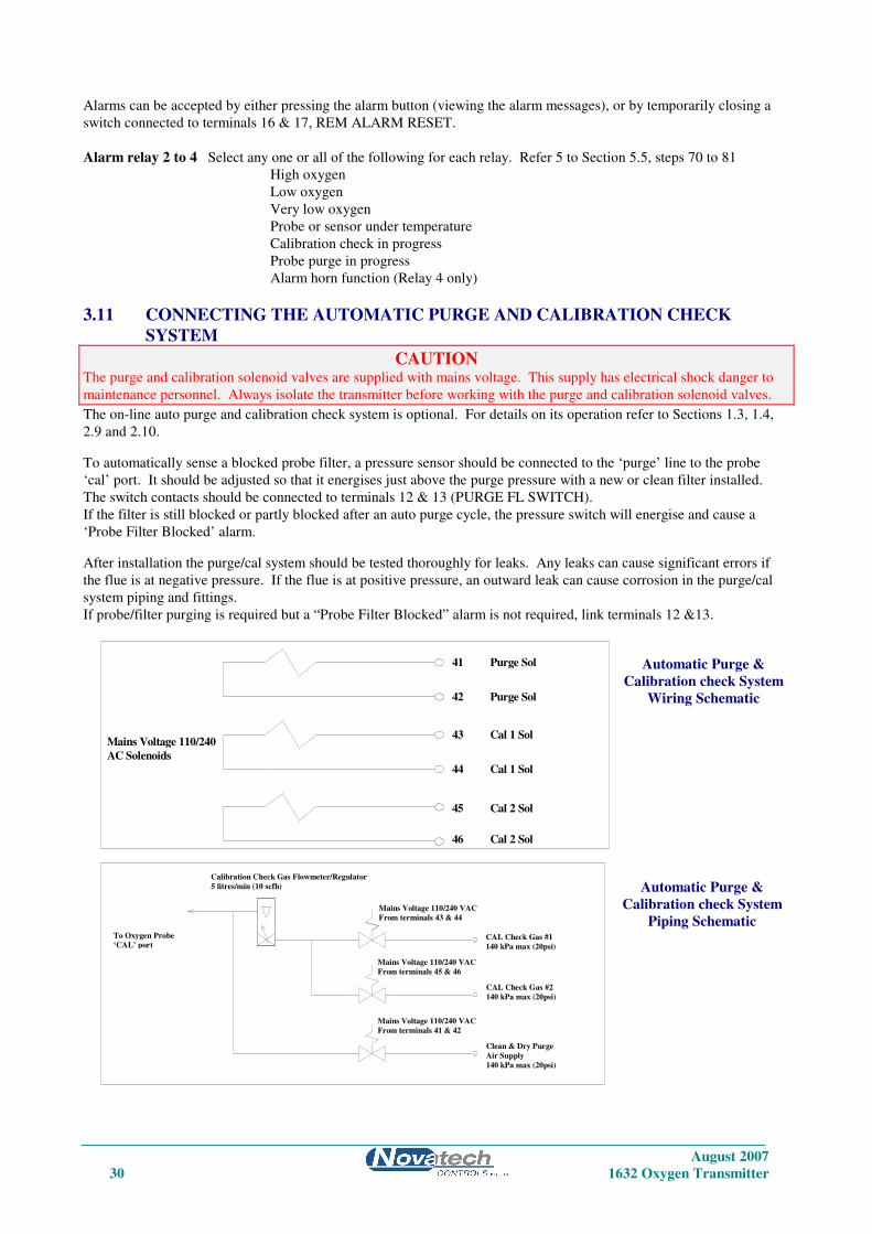
3.11 CONNECTING THE AUTOMATIC PURGE AND CALIBRATION CHECK
SYSTEM
CAUTION The purge and calibration solenoid valves are supplied with mains voltage. This supply has electrical shock danger to
maintenance personnel. Always isolate the transmitter before working with the purge and calibration solenoid valves.
The on-line auto purge and calibration check system is optional. For details on its operation refer to Sections 1.3, 1.4,
2.9 and 2.10.
To automatically sense a blocked probe filter, a pressure sensor should be connected to the ‘purge’ line to the probe
‘cal’ port. It should be adjusted so that it energises just above the purge pressure with a new or clean filter installed.
The switch contacts should be connected to terminals 12 & 13 (PURGE FL SWITCH).
If the filter is still blocked or partly blocked after an auto purge cycle, the pressure switch will energise and cause a
‘Probe Filter Blocked’ alarm.
After installation the purge/cal system should be tested thoroughly for leaks. Any leaks can cause significant errors if
the flue is at negative pressure. If the flue is at positive pressure, an outward leak can cause corrosion in the purge/cal
system piping and fittings.
If probe/filter purging is required but a “Probe Filter Blocked” alarm is not required, link terminals 12 &13.
Automatic Purge &
Calibration check System
Wiring Schematic
Automatic Purge &
Calibration check System
Piping Schematic
August 2007
1632 Oxygen Transmitter 31
3.12 CONNECTING REFERENCE AIR For 1234 sensors, no reference air connection is required. For oxygen probes, a 1/4” tube connector on the transmitter
should be connected via a nylon, copper or stainless steel tube the to ‘REF’ connector on the probe.
If two probes are being used, a “T” union must be supplied to provide reference air supply to both probes.
If ‘Internal’ is selected in set-up 85, and a reference airflow sensor is connected to CN8 on the 1630-2 (terminal) PCB,
the reference air pump is cycled on and off each minute.
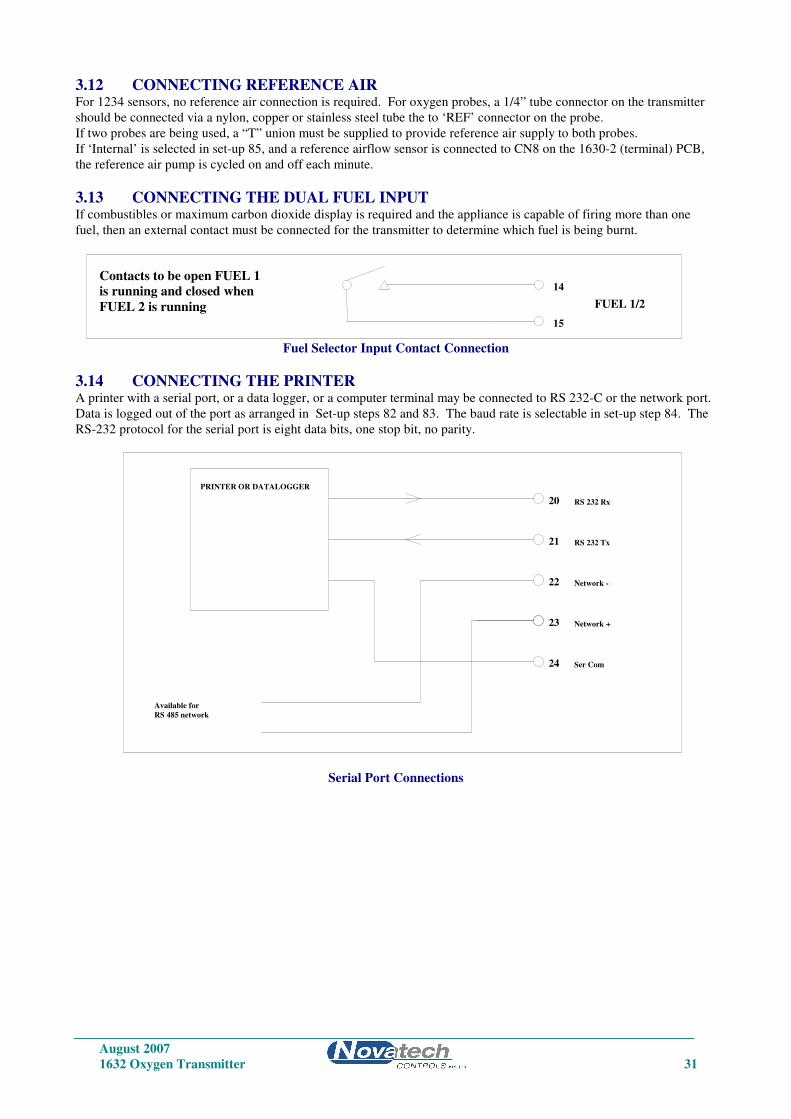
3.13 CONNECTING THE DUAL FUEL INPUT If combustibles or maximum carbon dioxide display is required and the appliance is capable of firing more than one
fuel, then an external contact must be connected for the transmitter to determine which fuel is being burnt.
Fuel Selector Input Contact Connection
3.14 CONNECTING THE PRINTER A printer with a serial port, or a data logger, or a computer terminal may be connected to RS 232-C or the network port.
Data is logged out of the port as arranged in Set-up steps 82 and 83. The baud rate is selectable in set-up step 84. The
RS-232 protocol for the serial port is eight data bits, one stop bit, no parity.
Serial Port Connections
Contacts to be open FUEL 1
is running and closed when
FUEL 2 is running
14
15
FUEL 1/2
Available for
RS 485 network
PRINTER OR DATALOGGER
Ser Com24
Network -
Network +23
22
RS 232 Rx
RS 232 Tx
20
21
August 2007
32 1632 Oxygen Transmitter
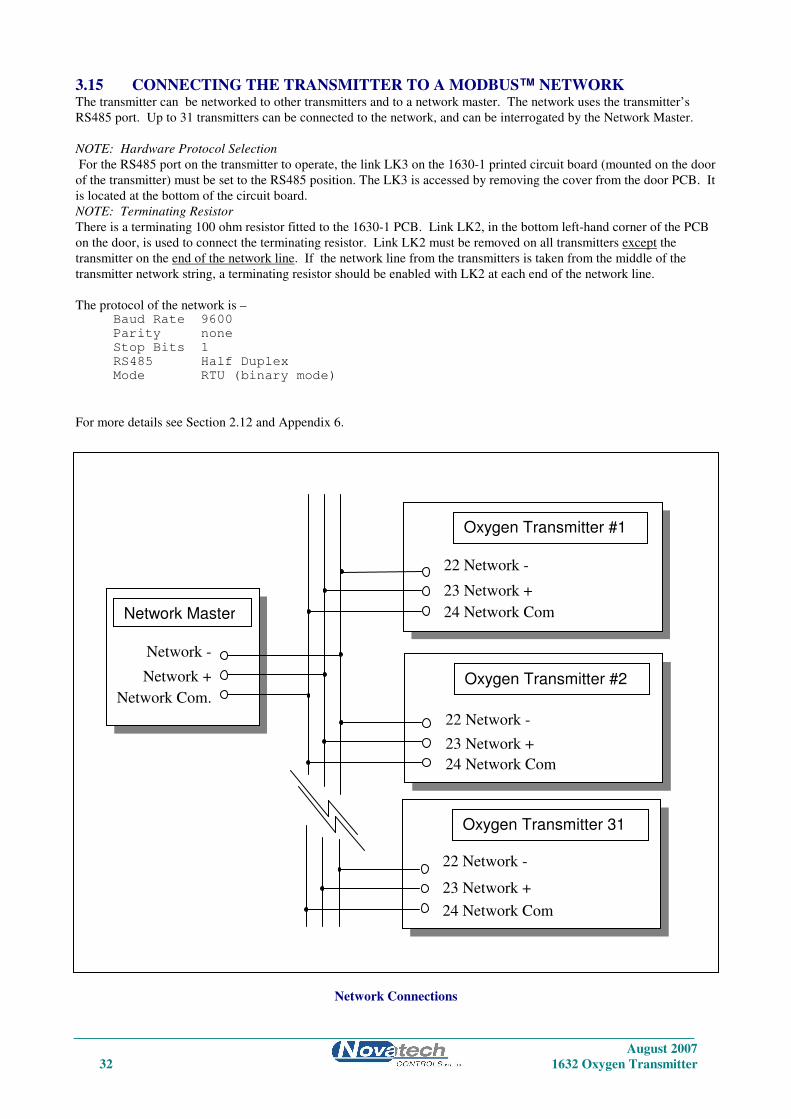
3.15 CONNECTING THE TRANSMITTER TO A MODBUS™ NETWORK The transmitter can be networked to other transmitters and to a network master. The network uses the transmitter’s
RS485 port. Up to 31 transmitters can be connected to the network, and can be interrogated by the Network Master.
NOTE: Hardware Protocol Selection
For the RS485 port on the transmitter to operate, the link LK3 on the 1630-1 printed circuit board (mounted on the door
of the transmitter) must be set to the RS485 position. The LK3 is accessed by removing the cover from the door PCB. It
is located at the bottom of the circuit board.
NOTE: Terminating Resistor
There is a terminating 100 ohm resistor fitted to the 1630-1 PCB. Link LK2, in the bottom left-hand corner of the PCB
on the door, is used to connect the terminating resistor. Link LK2 must be removed on all transmitters except the
transmitter on the end of the network line. If the network line from the transmitters is taken from the middle of the
transmitter network string, a terminating resistor should be enabled with LK2 at each end of the network line.
The protocol of the network is – Baud Rate 9600
Parity none
Stop Bits 1
RS485 Half Duplex
Mode RTU (binary mode)
For more details see Section 2.12 and Appendix 6.
Network Connections
Network -
Network +
Network Com.
22 Network -
23 Network +
24 Network Com
Oxygen Transmitter #1
22 Network -
23 Network +
24 Network Com
Oxygen Transmitter #2
22 Network -
23 Network +
24 Network Com
Oxygen Transmitter 31
Network Master

August 2007
1632 Oxygen Transmitter 33
COMMISSIONING
3.16 CONNECTING POWER Before commissioning the probe, sensor or transmitter, read the CAUTION paragraphs at the front of this manual.
Check that the mains supply voltage switch is set for the correct supply voltage, and that the green/yellow EARTH wire
MUST be connected to earth.
3.17 COMMISSIONING - SET-UP MODE Press the SET-UP button to select the ‘SET-UP’ mode. Most of the default settings of the functions will be correct, or
will have been pre-set at the factory. Refer to Section 5.5 for more details.
Check the following set-up functions -
2 to 6 Date /time
7 to 10 Reference voltages
11 & 12 Probe offset
22 & 23 Sensor type
26 & 27 Output channel #1
28 to 30 Output channel #2
53 Auto purge
67 Auto gas calibration checking
70 to 78 Alarm set-up
3.18 COMMISSIONING - RUN MODE When the transmitter is turned on it will go to RUN mode. The SET-UP/RUN button will toggle between the two
modes. The upper line of the display will now read ‘% OXYGEN’. If the probe or sensor temperature is not above
650°C (1200°F), a “Probe Low Temperature” message is flashed on the lower line. The probe or sensor temperature
can be checked on the lower line of the display.
3.19 BURNER BY-PASS SWITCH Heated probes and sensors should have their heater supply interlocked. If the combustion appliance is not running, then
power will not be supplied to the heater. To commission an oxygen probe when the main burner is turned off, switch
power off the transmitter, remove the probe from the flue or the flue connection from the 1234 sensor.
Re-apply power to the transmitter, press the BURNER BY-PASS switch into the ‘DOWN’ or ‘ON’ position. This will
apply power to the probe or sensor heater even when the plant is not running. The offset can now be set and calibration
checked with appropriate calibration check gases (typically 2% oxygen in nitrogen).
Ensure that the burner by-pass switch and the power are turned off before the probe or sensor is re-installed. An alarm
will occur if the BURNER BY-PASS switch is turned on (down) during normal operation.
3.20 CHECKING THE ALARMS If any alarms are present the alarm LED will be lit, either flashing or steady. To interpret the alarms, press the alarm
button until all alarm functions have been displayed. Rectify the cause of each alarm until no further alarms appear on
the display. For details on the operation of the alarm button and the alarm functions refer to Section 4.
3.21 PROBE OR SENSOR CALIBRATION The zirconia sensor provides an absolute measurement of oxygen partial pressure. There are no calibration adjustments,
apart from ‘SENSOR OFFSET’, for the probe or sensor. The zirconia sensor EMF is either correct or replacement is
required. To check that the probe or sensor is functioning correctly, firstly check that the high impedance alarm,
‘SENSOR FAIL’, is not active. The actual impedance can be displayed on the lower line. It should be less than 9 KΩ at
720°C (1320°F).
Once it has been established that the impedance is normal, the offset may be set using the millivolt level marked on the
oxygen probe or sensor. Refer to Section 5.5.11. The probe offset can be tested on site. A small flow of air must be
admitted to both the ‘REF’ and ‘CAL’ ports when testing the probe offset. If the probe is in the process, the air must
fully purge the probe sensor without interference from the process gas sample. Novatech probes can easily achieve this
August 2007
34 1632 Oxygen Transmitter
with or without a probe filter and a gas flow of only 1 to 5 litres/minute (120 to 600 scfm) for a 1231 probe and up to 20
litres/minute (2400scfm) for an unheated probe.
3.22 FILTER PURGING Purging probe filters is controlled from the ‘PURGE’ button on the transmitter when in ‘RUN’ mode. If ‘AUTO
PURGE’ has been enabled in set-up 53, pressing the PURGE button will start the automatic cycle. Pressing any other
button will cancel the auto purge cycle. If AUTO PURGE was not enabled, the purge solenoid will only stay open for
as long as the button is pressed. Gradually adjust the purge air supply regulator, increasing the pressure until sufficient
flow is obtained to clear the filter. This is best checked with a dirty filter after a period of operation, by withdrawing the
probe from service and watching any build up on the filter being blown off at the set pressure. Normally 30 kPa (5 psi)
is adequate but the air pressure may be set as high as 100 kPa (15 psi).
3.23 CALIBRATION GAS CHECK If the installation has a filter purge facility, set this up first. Refer to the previous paragraph. Press the ‘CAL 1 or ‘CAL
2’ button while in ‘SET UP’ mode to obtain a reasonable flow through the calibration check gas flow meter. If air is
being used as a calibration check gas, use the air from the regulator for filter purge. Then, when setting up a gas for
calibration checking, set the pressure from the calibration gas cylinder so that it is the same as the pressure set on the air
regulator. Then the setting on the rotameter / flow regulator will be the same as that for the airflow. The flow required
is 1 to 5 litres/minute (120 to 600 scfm) ) for a 1231 probe and up to 20 litres/minute (2400scfm) for an unheated probe.
Air is not the best gas for calibration checking on a zirconia sensor. The output of a zirconia sensor with air on both
sides of the sensor is zero millivolts. It is better to choose a gas value which provides a reasonable output from the
sensor and which is near to the process oxygen level. A cylinder with 2% oxygen in nitrogen is a commonly used
calibration gas. The maximum pressure on the calibration check gas cylinder regulators is 100 kPa (15 psi).
Note: If two probes was selected in set-up 1, ‘Cal Gas 2’ must be connected to probe 2.
3.24 DUST IN THE FLUE GAS For unheated probes with no filter, entrained solids or dust in the flue gas does not present a problem unless the dust,
when settled, is not porous. Allow the dust in the process to build up on the probe. It will form a porous layer slowing
the response time. To avoid mechanical abrasion of the electrode material in installations with unheated oxygen probes,
pack ‘SAFFIL’ or equivalent alumina based ceramic fibre in the sensing holes to protect the electrode. Do not use silica
based ceramic fibres such as ‘KAOWOOL’, which can attack the electrode at high temperatures. Once the dust has built
up the response time of the probe will be slower.
For heated probes the preferred method of mounting for dust-laden applications is facing vertically downwards with the
filter removed. Probes can also be mounted horizontally with no filter with some dusts. An occasional automatic back
purge is helpful in this case.
Normally heated probes are supplied with filters for applications with particulates in the flue gas. The probe response
time should be tested when the probe is first installed, and then regularly until it remains constant for a significant
period. Filter purging should be set up on the time periods determined by these tests. To test the probe response time,
use a stopwatch to obtain the time for a probe to achieve a 63 % change from one reading to another. If a probe filter
blocks completely in a short period of time, then there is no option but to use the probe without the filter. A trial probe
with filter can be installed to test whether a filter blockage is likely to occur.
3.25 STRATIFICATION If the transmitter and probe have been fully tested and the oxygen readings in the flue gas are incorrect, gas stratification
may be occurring. The phenomena cannot be anticipated for any particular installation. Generally, large flues have
oxygen differences of approximately one percent across the flue. Occasionally an oxygen error of several percent may
occur in a flue of any size. Moving the probe to a new location normally solves this problem.
The effects of stratification can be reduced by using two probes and averaging the two oxygen readings. This can be
achieved within a Novatech 1632 transmitter controlling two probes.
August 2007
1632 Oxygen Transmitter 35
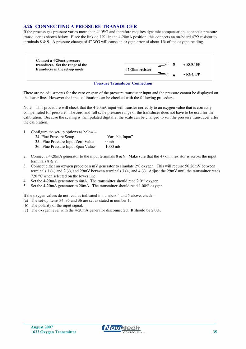
3.26 CONNECTING A PRESSURE TRANSDUCER If the process gas pressure varies more than 4” WG and therefore requires dynamic compensation, connect a pressure
transducer as shown below. Place the link on LK1 in the 4-20mA position, this connects an on-board 47Ω resistor to
terminals 8 & 9. A pressure change of 4” WG will cause an oxygen error of about 1% of the oxygen reading.
Pressure Transducer Connection
There are no adjustments for the zero or span of the pressure transducer input and the pressure cannot be displayed on
the lower line. However the input calibration can be checked with the following procedure.
Note: This procedure will check that the 4-20mA input will transfer correctly to an oxygen value that is correctly
compensated for pressure. The zero and full scale pressure range of the transducer does not have to be used for the
calibration. Because the scaling is manipulated digitally, the scale can be changed to suit the pressure transducer after
the calibration.
1. Configure the set-up options as below –
34. Flue Pressure Setup- “Variable Input”
35. Flue Pressure Input Zero Value- 0 mb
36. Flue Pressure Input Span Value- 1000 mb
2. Connect a 4-20mA generator to the input terminals 8 & 9. Make sure that the 47 ohm resistor is across the input
terminals 8 & 9.
3. Connect either an oxygen probe or a mV generator to simulate 2% oxygen. This will require 50.26mV between
terminals 1 (+) and 2 (-), and 29mV between terminals 3 (+) and 4 (-). Adjust the 29mV until the transmitter reads
720 °C when selected on the lower line.
4. Set the 4-20mA generator to 4mA. The transmitter should read 2.0% oxygen.
5. Set the 4-20mA generator to 20mA. The transmitter should read 1.00% oxygen.
If the oxygen values do not read as indicated in numbers 4 and 5 above, check –
(a) The set-up items 34, 35 and 36 are set as stated in number 1.
(b) The polarity of the input signal.
(c) The oxygen level with the 4-20mA generator disconnected. It should be 2.0%.
Connect a 4-20mA pressure
transducer. Set the range of the
transducer in the set-up mode.
8
9 - RGC I/P
+ RGC I/P
47 Ohm resistor

August 2007
36 1632 Oxygen Transmitter

August 2007
1632 Oxygen Transmitter 37
OPERATOR FUNCTIONS
4
SECTION
NUMBER
4.1 DISPLAY BUTTON
4.2 ALARM BUTTON
4.3 ALARM SCHEDULE
4.4 POWER LAMP
4.5 BURNER BYPASS SWITCH
4.6 DISPLAY BACKLIGHT
August 2007
38 1632 Oxygen Transmitter
OPERATOR FUNCTIONS (RUN MODE)
4.1 DISPLAY BUTTON The upper line on the display will always read % oxygen (or ppm, selectable in step 31 in the set-up menu Section 5.5)
for sensor 1. The following are available for display on the lower line.
1. AVERAGE OF PROBE 1 & PROBE 2 OXYGEN,
2. PROBE 2 OXYGEN,
3. PROBE 1 EMF (millivolts)
4. PROBE 2 EMF (millivolts)
5. PROBE 1 TEMPERATURE
6. PROBE 2 TEMPERATURE
7. PROBE 1 IMPEDANCE,
8. PROBE 2 IMPEDANCE, A measure of integrity of the sensor's electrode, the part of the probe that normally wears
out first.
9. AUXILIARY TEMPERATURE
10. AMBIENT TEMPERATURE
11. OXYGEN DEFICIENCY %
12. COMBUSTIBLES %
13. % CARBON DIOXIDE, dry. Calculated from the oxygen reading. Assumes complete combustion.
14. RUN HOURS SINCE LAST SERVICE
15. DATE OF LAST SERVICE
Any number of these variables can be displayed sequentially by pressing the ‘DISPLAY’ button. Items can be selected
for display or deleted in step 33, in the set-up menu Section 5.5, on the keyboard. In addition to the above lower line
displays, the transmitter will automatically display:
“Sensor 1 Temp Low”, when sensor one is below 650°C (1200°F)
“Sensor 2 Temp Low”, when sensor two is below 650°C (1200°F)
“Gas 1 ON”, “Gas 2 ON” for Calibration check Gas 1 or 2
“Purging Probe”
“Sensor 1 Thermocouple Wrong Polarity”
“Sensor 2 Thermocouple Wrong Polarity”
“Aux Thermocouple Wrong Polarity”
NOTE: 1. The run time will be the period of time the BURNER ON SWITCH (terminals 18 & 19) contact is closed (ie. main
fuel valve open). If no explosion protection is required, a permanent bridge between the BURNER ON SWITCH
terminals will register run time whenever the transmitter is powered.
2. This timer can be used as a probe replacement and/or boiler service schedule aid. Changing the ‘SERVICE DAY’ in
set-up mode on the keyboard resets the start time.
3. If you hold the display button down as you switch on the power, the maximum ambient temperature which the
instrument has been subjected to, will be displayed. This temperature should be less than 50°C (130°F).
August 2007
1632 Oxygen Transmitter 39
4.2 ALARM BUTTON Repeatedly pressing the ‘ALARM’ button will produce alarm displays in sequence on the lower line of the LCD display.
If an alarm has cleared prior to pressing the ‘ALARM’ button, it will not re-appear on a second run through the alarms.
Active alarms which have been previously displayed will have ‘acc’ (accepted in lower case), displayed alongside. New
alarms will not have ‘ACC’ (in upper case) displayed until a second press of the ‘ALARM’ button. After the last active
alarm is indicated, the lower line of the display will return to the last displayed lower line variable. Alarms may also be
accepted remotely by a temporary closure of a switch connected to terminal 16 & 17, ‘REMOTE ALARM RESET’.
The alarm ‘LED’ will flash when there is an un-accepted alarm. Pressing the ‘ALARM’ button will cause the LED to go
steady if any alarms are still active, or extinguish if there are no active alarms. The horn relay will operate when an
alarm occurs. Pressing ‘ALARM’ will mute a horn relay (if one of the user configurable relays have been selected as a
‘Horn’ relay) which will re-initiate on any new alarms.
4.3 ALARM SCHEDULE
4.3.1 SUMMARY OF ALARMS - COMMON ALARM
1. ‘Sensor 1 Fail’
2. ‘Sensor 2 Fail’
Oxygen sensor or electrode failure (high impedance); (inhibited under 650°C (1200°F)).
3. ‘Heater 1 Fail’
4. ‘Heater 2 Fail’
In the first 20 minutes of power being applied to the heater after being switched on, this alarm will not occur, but a
‘Sensor 1(2) Lo Temp’ display will occur and common alarm relay will be activated. Refer to Section 6.11. If an ADC
alarms occurs, the heaters will automatically be turned off.
5. ‘Sensor 1 TC Open’
6. ‘Sensor 2 TC Open’
Probe thermocouple is open circuit. The heater in heated probes will switch off.
7. ‘Aux TC Open’
Stack thermocouple is open circuit. If the thermocouple is not needed, select “NO T/C” for “Aux TC Type” or place a
short circuit between terminals 5 & 6.
8. ‘Ref Pump Fail’
The reference air pump in the transmitter has failed.
9. ‘Ref Air Fail’
The reference gas supply from the air pump in the transmitter to the probe is blocked, or there is not sufficient airflow.
10. ‘ADC Cal Fail’
The analog to digital converter has been found to fall outside the normal calibration specifications. In this case the
sensor heater will automatically be turned off.
11. ‘Mains Freq’
The sample of the mains frequency has failed.
12. ‘DAC Cal Fail’
The digital to analog and voltage isolator circuit has been found to fall outside the normal calibration specifications.
This check is only performed when the ‘AUTO CAL’ button is pressed. Refer to Section 6.3.
13. ‘Probe Filter
Blocked probe filter. This test is only performed when automatic purging of the probe is selected. Refer to step 53 in
the set-up menu Section 5.5. This alarm will not reset until the next purge cycle that can be initiated manually or
automatically.
14. ‘Gas 1 Cal Err’
Probe does not correctly calibrate to calibration check gas 1.
August 2007
40 1632 Oxygen Transmitter
15. ‘Gas 2 Cal Err’
Probe does not correctly calibrate to calibration check gas 2.
16. ‘Burner bypass’
The safety interlock relay has been bypassed by turning on the ‘BURNER BYPASS’ switch on the terminal printed
circuit board. Refer to Section 3.19
17. ‘Oxygen Deviation High’
The oxygen as read by sensor 1 differs from the oxygen read by sensor 2 by an amount greater than the level set in step
75 in the set-up menu Section 5.5, for a period longer than that set in step 76. This alarm is only available if ‘Two
Sensors’ is selected in set-up 1.
18. ‘Watchdog Timer’
Microprocessor error. This alarm will not appear on the display. The common alarm relay will be forced open circuit.
If the watchdog timer senses a malfunction in the microprocessor, it will attempt to reset the transmitter every 2 seconds.
After two resets the alarm relay contacts will go open circuit.
19. ‘BBRAM Fail”
The battery backed memory module has failed in service. The device normally lasts 10 years. It is the plug-in battery
like module on the 1630 -1 board, labelled M1.
20. ‘Htr SSR Fail”
One of the two solid state relays that drive the heaters in the oxygen sensors has failed. The electro-mechanical relay
RL7 will cut off the heater to prevent further damage.
4.3.2 SUMMARY OF ALARMS - SELECTABLE ALARMS
There are three user configurable alarm relays. Any or all of the following functions can be selected for each relay.
NOTE: The process alarms will only be activated if enabled in set-up 70.
21. ‘O2% Low’
The measured oxygen level is below the level set in set-up 73, and the alarm delay set in set-up 74 has expired. See step
64 in the set-up menu Section 5.5 for more details.
22. ‘O2% Very Low’
The measured oxygen level is below the level set in set-up 77, and the alarm delay set in set-up 78 has expired. See step
66 in the set-up menu Section 5.5 for more details.
23. ‘O2% High’
The measured oxygen level is above the level set in set-up 71, and the alarm delay set in set-up 72 has expired. See step
62 in the set-up menu Section 5.5 for more details.
24. ‘Probe Temperature’
The probe temperature is under 650°C (1200°F). The oxygen reading is therefore invalid. If the probe heater has been
on for more than 20 minutes and the temperature is less than 650°C (1200°F) a ‘heater fail’ alarm will occur.
NOTE:
The ‘Probe Temp’ relay function is used with unheated probes to indicate oxygen reading is invalid (the probe is below
650°C (1200°F) ), in case the process temperature falls below this level. With heated probes this relay will be de-
energised while the probe is heating up from ambient, making the contacts open circuit.
25. ‘Cal in Progress’
A calibration check is occurring, either manual ( in RUN mode) or automatic
Probe Purge
A probe purge is occurring, either manual ( in RUN mode) or automatic
26. Alarm Horn
This is not an alarm condition. If one of the three user configurable alarm relays have ‘Alarm Horn’ enabled; the relay
will have closed contacts only when there is an unaccepted alarm on the transmitter. Press the alarm button twice to
accept any new alarm and to cancel the horn relay. This is only available on relay 4.
August 2007
1632 Oxygen Transmitter 41
4.3.3 ALARM RELAYS
The alarm relays are fail safe. That is, the contacts will be closed during normal operation, and will be open circuit if
there is an alarm or if the power is removed from the transmitter.
4.4 POWER LAMP Illuminates when power is connected to the transmitter. If the lamp is flashing, the watchdog timer is attempting to reset
the microprocessor. Replace the 1630-1 microprocessor PCB.
4.5 BURNER BYPASS SWITCH This switch is mounted on the terminal PCB near the POWER switch.
Before the heater in a heated probe, or the alarms will be enabled, the probe must be enabled. There are two ways of
doing this.
Use the safety interlock on terminals 18 & 19 (BURNER ON switch), or press the BURNER BYPASS switch to the ON
position. While the BURNER BYPASS switch is on there will be an alarm, “Burner Bypass”.
If it is not needed to have the transmitter interlocked with the combustion appliance terminals 18 & 19 can be connected
together.
4.6 DISPLAY BACKLIGHT If the ambient temperature measured inside the transmitter cabinet exceeds 35°C, the backlight will be turned off one
minute after the keypad is used. This is aimed at reducing one of the major sources of heat within the cabinet when the
ambient temperature is high. The backlight will come on again as soon as a button is pressed.
The internal reference air pump (if fitted) will start cycling on and off every minute, above 35°C.

August 2007
42 1632 Oxygen Transmitter

August 2007
1632 Oxygen Transmitter 43
SETTING UP THE
TRANSMITTER
5
SECTION
NUMBER
5.1 SET-UP MODE SUMMARY
5.2 SET-UP & RUN MODES
5.3 FUNCTION SELECT
5.4 ENTER OPTION OR VALUE
5.5 SET-UP FUNCTION DETAILS

August 2007
44 1632 Oxygen Transmitter
SET-UP MODE SUMMARY
5.1 SET-UP MODE FUNCTIONS
1 Number of Sensors
2 Calendar Year
3 Calendar Month
4 Calendar Day
5 Real time clock Hour
6 Real time clock Minutes
7 Reference voltage #1
8 Reference voltage #2
9 Reference voltage #3
10 Reference voltage #4
11 Sensor 1 offset
12 Sensor 2 offset
13 Output channel number 1 calibration
14 Output channel number 1 calibration, 4mA trim
15 Output channel number 1 calibration, 20mA trim
16 Output channel number 2 calibration
17 Output channel number 2 calibration, 4mA trim
18 Output channel number 2 calibration, 20mA trim
19 Service record year
20 Service record month
21 Service record day
22 Sensor 1 Type
23 Sensor 2 Type
24 Sensor 1 Thermocouple Type
25 Sensor 2, Auxiliary Thermocouple Type
26 Transmitter Output Channel 1 scale
27 Transmitter Span Channel 1
28 Transmitter Output Channel 2 scale
29 Transmitter Zero Channel 2
30 Transmitter Span Channel 2
31 Top Line Display Units, % or ppm
32 Centigrade/Fahrenheit Selection
33 Lower Line Display Functions
34 Flue Pressure, Fixed/Variable
35 Flue Pressure Input Zero Level
36 Flue Pressure Input Span Level
37 Flue Pressure mm/inches/kilopascals
38 Flue Pressure Value
Set-up steps 39 to 51 will be skipped automatically if combustibles, maximum CO2 or oxygen deficiency are not
selected in steps 28, 33 or 82.
39 Single or Dual Fuel
40 Fuel #1 ‘A’ Value
41 Fuel #1 ‘H’ Value
42 Fuel #1 ‘O’ Value
43 Fuel #1 ‘N’ Value
44 Fuel #1 ‘S’ Value
45 Fuel #1 ‘M’ Value
Set-up steps 46 to 51 will be skipped automatically if ‘Single Fuel’ is selected in set-up step 39.
46 Fuel #2 ‘A’ Value
47 Fuel #2 ‘H’ Value
48 Fuel #2 ‘O’ Value
49 Fuel #2 ‘N’ Value
50 Fuel #2 ‘S’ Value
51 Fuel #2 ‘M’ Value
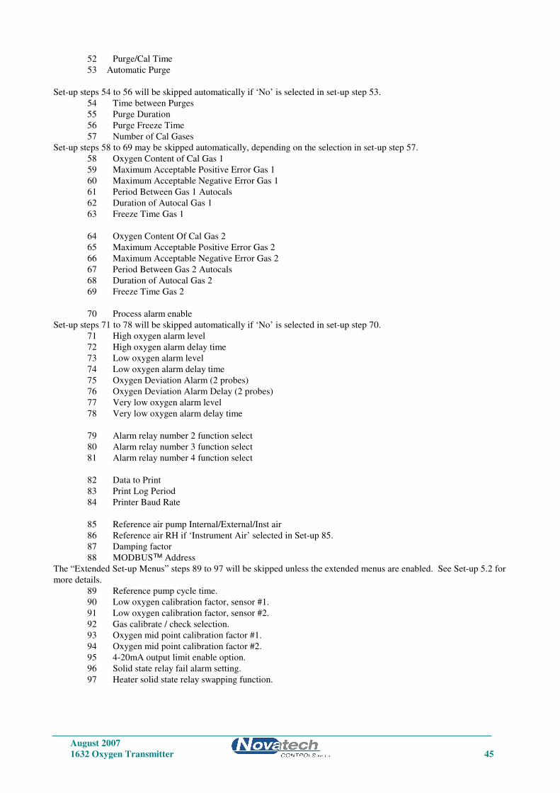
August 2007
1632 Oxygen Transmitter 45
52 Purge/Cal Time
53 Automatic Purge
Set-up steps 54 to 56 will be skipped automatically if ‘No’ is selected in set-up step 53.
54 Time between Purges
55 Purge Duration
56 Purge Freeze Time
57 Number of Cal Gases
Set-up steps 58 to 69 may be skipped automatically, depending on the selection in set-up step 57.
58 Oxygen Content of Cal Gas 1
59 Maximum Acceptable Positive Error Gas 1
60 Maximum Acceptable Negative Error Gas 1
61 Period Between Gas 1 Autocals
62 Duration of Autocal Gas 1
63 Freeze Time Gas 1
64 Oxygen Content Of Cal Gas 2
65 Maximum Acceptable Positive Error Gas 2
66 Maximum Acceptable Negative Error Gas 2
67 Period Between Gas 2 Autocals
68 Duration of Autocal Gas 2
69 Freeze Time Gas 2
70 Process alarm enable
Set-up steps 71 to 78 will be skipped automatically if ‘No’ is selected in set-up step 70.
71 High oxygen alarm level
72 High oxygen alarm delay time
73 Low oxygen alarm level
74 Low oxygen alarm delay time
75 Oxygen Deviation Alarm (2 probes)
76 Oxygen Deviation Alarm Delay (2 probes)
77 Very low oxygen alarm level
78 Very low oxygen alarm delay time
79 Alarm relay number 2 function select
80 Alarm relay number 3 function select
81 Alarm relay number 4 function select
82 Data to Print
83 Print Log Period
84 Printer Baud Rate
85 Reference air pump Internal/External/Inst air
86 Reference air RH if ‘Instrument Air’ selected in Set-up 85.
87 Damping factor
88 MODBUS™ Address
The “Extended Set-up Menus” steps 89 to 97 will be skipped unless the extended menus are enabled. See Set-up 5.2 for
more details.
89 Reference pump cycle time.
90 Low oxygen calibration factor, sensor #1.
91 Low oxygen calibration factor, sensor #2.
92 Gas calibrate / check selection.
93 Oxygen mid point calibration factor #1.
94 Oxygen mid point calibration factor #2.
95 4-20mA output limit enable option.
96 Solid state relay fail alarm setting.
97 Heater solid state relay swapping function.
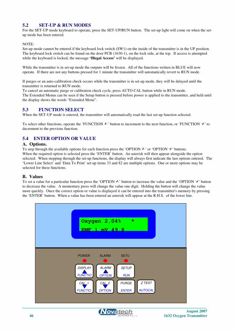
August 2007
46 1632 Oxygen Transmitter
5.2 SET-UP & RUN MODES For the SET-UP mode keyboard to operate, press the SET-UP/RUN button. The set-up light will come on when the set-
up mode has been entered.
NOTE:
Set-up mode cannot be entered if the keyboard lock switch (SW1) on the inside of the transmitter is in the UP position.
The keyboard lock switch can be found on the door PCB (1630-1), on the lock side, at the top. If access is attempted
while the keyboard is locked, the message ‘Illegal Access’ will be displayed.
While the transmitter is in set-up mode the outputs will be frozen. All of the functions written in BLUE will now
operate. If there are not any buttons pressed for 1 minute the transmitter will automatically revert to RUN mode.
If purges or an auto-calibration check occurs while the transmitter is in set-up mode, they will be delayed until the
transmitter is returned to RUN mode.
To cancel an automatic purge or calibration check cycle, press AUTO CAL button while in RUN mode.
The Extended Menus can be seen if the Setup button is pressed before power is applied to the transmitter, and held until
the display shows the words “Extended Menu”.
5.3 FUNCTION SELECT When the SET-UP mode is entered, the transmitter will automatically read the last set-up function selected.
To select other functions, operate the ‘FUNCTION ’ button to increment to the next function, or ‘FUNCTION ’ to
decrement to the previous function.
5.4 ENTER OPTION OR VALUE
A. Options. To step through the available options for each function press the ‘OPTION ’ or ‘OPTION ’ buttons.
When the required option is selected press the ‘ENTER’ button. An asterisk will then appear alongside the option
selected. When stepping through the set-up functions, the display will always first indicate the last options entered. The
‘Lower Line Select’ and ‘Data To Print’ set-up items 33 and 82 are multiple options. One or more options may be
selected for these functions.
B. Values To set a value for a particular function press the ‘OPTION ’ button to increase the value and the ‘OPTION ’ button
to decrease the value. A momentary press will change the value one digit. Holding the button will change the value
more quickly. Once the correct option or value is displayed it can be entered into the transmitter's memory by pressing
the ‘ENTER’ button. When a value has been entered an asterisk will appear at the R.H.S. of the lower line.
1632 Oxygen TRANSMITTER Keyboard
Oxygen 2.04% *
EMF 1 mV 49.8
CAL 1
FUNCTIO
N
CAL 2
OPTION
PURGE
ENTER
Z TEST AUTOCAL
SETUP
RUN
ALARM
OPTION
DISPLAY
FUNCTIO
POWER ALARM SETU
August 2007
1632 Oxygen Transmitter 47
5.5 SET-UP FUNCTION DETAILS
Note: The * indicates the default setting after a COLD-START. See Section 6.1
1. Number of sensors Options
Select the number of oxygen probes or sensors being used.
1 Sensor *
2 Sensors
2. Calendar year Options
Select the current year for the real time clock / calendar.
The cold start default sets the date and time to the software version date.
3. Calendar month Options
Select the current month for the real time clock / calendar.
4. Calendar day Options
Select the current day for the real time clock / calendar.
5. Real time12:20:53 PM clock hour Options Select the current hour for the real time clock. (24 hour format)
6. Real time clock minutes Options
Select the current minutes for the real time clock.
7. Reference voltage # 1 (about 27.5 mV) Options
Set the value of the reference voltage as read on a 3 1/2 digit multimeter (See Section 6.2 for further details).
27.55 mV *
8. Reference voltage # 2 (about 194 mV) Options
Set the value of the reference voltage as read on a 3 1/2 digit multimeter (See Section 6.2 for further details).
193.60 mV *
9. Reference voltage # 3 (about 1200 mV) Options
Set the value of the reference voltage as read on a 3 1/2 digit multimeter (See Section 6.2 for further details).
1202.00 mV *
10. Reference voltage # 4 (about 2500 mV) Options
Set the value of the reference voltage as read on a 3 1/2 digit multimeter (See Section 6.2 for further details).
2479.00 mV *
Set-up items 7 to 10 are used to calibrate the A/D of the instrument. This should be done 30 minutes or more after the
instrument has been on, approximately once every year. The calibration constants are retained in battery backed
memory unless a ‘COLD START’ is performed. Connect a 3 1/2 digit multimeter negative lead to the test point marked
‘C’ to the right of the PCB on the inside of the door (labelled ‘REF VOLTS’). Measure the four voltages on the test
point marked 1 to 4 with the positive lead. Refer to Figure 6.2 in the 1632 manual. Enter the measured values in set-up
items 7 to 10. Whenever new values are entered the D/A Section should be re-calibrated, Refer to Section 6.3.
August 2007
48 1632 Oxygen Transmitter
11. Set Probe or Sensor 1 Offset See function 12
12. Set Probe or Sensor 2 Offset (When 2 sensors are selected in set-up 1)
A new EMF offset must be entered whenever a new oxygen probe or sensor is installed to calibrate for any offset an
individual probe or sensor may have. Each probe or sensor will have an offset value noted on a removable tag. Enter
the ‘SENSOR OFFSET’ value with the same polarity,
eg. if offset value is -1.2 mV. enter -1.2 mV. The typical maximum is +/- 2mV.
To check a probe offset on site, the probe must be sensing air, with reference air, and allowed to settle at the probe
operating temperature for 30 minutes. Read the offset in ‘RUN’ mode in millivolts on the lower line. Offset errors can
occur if the sensor does not have some air passing over it. A gentle flow of air in the calibration check port can be
provided by a reference air pump or similar.
For heated probes, if the combustion appliance is not operational and the probe heater is interlocked with the ‘BURNER
ON’ signal, the ‘BURNER BYPASS’ switch should be set to ‘ON to power the probe heater after removing the probe
from the flue.
CAUTION DANGER
Return the ‘BURNER BYPASS’ switch to normal (off) before installing the probe in the flue.
For unheated probes, the probe sensing tip must be raised to at least 650°C (1200°F) with a portable furnace.
Determine the probe offset in ‘RUN’ mode. Select ‘Sensor EMF’ on the lower line. With probe in air, stabilised at
temperature for 30 minutes, read the ‘Sensor EMF’. Switch back to ‘set-up’ mode and enter ‘Sensor Offset’ of equal
value and the same polarity.
eg. If the measured ’SENSOR OFFSET’ was -1.2 mV, enter -1.2 mV.
When reading the EMF offset, the flue pressure compensation must be set. If the probe has been removed from the flue,
set the flue pressure compensation set up to “Fixed” in set-up 34, and the value to 0 in set-up step 38.
13. 4 to 20 mA Calibration Options, Channel #1 Select the calibration method for the 4-20mA output channel #1.
The output channels can be either calibrated by simply pressing the ‘AUTO CAL’ button, or can be trimmed at both the
4mA and 20mA ends of the scale using an external multimeter.
Options:
1. Auto Calibration *
2. Manual Calibration
3. Set 4mA Trim
4. Set 20mA Trim
If ‘AUTO CAL’ is selected, the output channel is calibrated when ‘Auto Cal’ is initiated from the keyboard (See Section
6.3).
If ‘MAN CAL’ is selected, it is necessary to trim both ends of the 4-20mA output range using the 4mA and 20mA
options in this menu item. Selecting ‘MAN CAL’ inhibits the ‘Auto Cal’ process of this channel.
Always do the 4mA trim first, and then the 20mA trim. After trimming both ends of the scale, return the
‘CALIBRATION OPTIONS’ menu option back to ‘MAN CAL’ (not ‘AUTO CAL’), or the calibration factors will be
over written by the next ‘AUTO CAL’.
For more details on calibrating the output channels, see Section 6.3.
NOTE: The transmitter will only stay in either ‘4mA TRIM’ or ‘20mA TRIM’ modes for 30 minutes before it
automatically returns to ‘MAN CAL’.
14. Calibrate 4mA, Channel #1 This menu item only appears if ‘Set 4mA Trim’ is selected in Set-up 13.
Range: 0 to 25mA, Default is 4.00mA
For full details on the calibration of the 4-20mA output channels, see Section 6.3.

August 2007
1632 Oxygen Transmitter 49
15. Calibrate 20mA, Channel #1 This menu item only appears if ‘Set 20mA Trim’ is selected in Set-up 13.
Range: 0 to 25mA, Default is 20.00mA
16. 4 to 20 mA Calibration Options, Channel #2 Select the calibration method for the 4-20mA output channel #1.
For more details, see Set-up 13 and Section 6.3.
Options:
1. Auto Calibration *
2. Manual Calibration
3. Set 4mA Trim
11. Set 20mA Trim
17. Calibrate 4mA, Channel #2 This menu item only appears if ‘Set 4mA Trim’ is selected in Set-up 16.
Range: 0 to 25mA, Default is 4.00mA
For full details on the calibration of the 4-20mA output channels, see Section 6.3.
18. Calibrate 20mA, Channel #2 This menu item only appears if ‘Set 20mA Trim’ is selected in Set-up 16.
Range: 0 to 25mA, Default is 20.00mA
19. Enter Service Year For a new ‘DATE OF LAST SERVICE’, enter the service ‘YEAR’. This can represent the last time the probe or sensor
was serviced or the last time the boiler was serviced. It is recommended that probes and sensors be refurbished every
two years
20. Enter Service Month Enter the current ‘MONTH’.
21. Enter Service Day Enter the current ‘DAY’ of the month. Altering these values will reset the ‘RUN TIME’.
22. Sensor 1 Type
23. Sensor 2 Type Options:
Model No. Enter the probe or sensor model number in use
1. 1231/1234 Heated * Heated Probe or sensor
2. 1232 Unheated Unheated Probe
24. Probe or Sensor 1 Thermocouple Type See function 25
August 2007
50 1632 Oxygen Transmitter
25. Probe or Sensor 2 Thermocouple Type (When 2 sensors are selected in set-up 1)
Auxiliary Thermocouple Type (When 1 sensor is selected in set-up 1) The probe can have either a type K, or R thermocouple as a sensor temperature detector. A 1231 probe or a 1234 sensor
will always have a K thermocouple, and a 1232 will usually have an R thermocouple.
Options:
1. K * Check in the manual Section 1
2. R for the probe model number.
3. NO T/C If no TC type is to be used for an Auxiliary use.
NOTE
For heated probes the flue (auxiliary) thermocouple is a separate sensor from the oxygen probe and should be mounted
near to and upstream from the probe. It is optional. If no thermocouple is required, select option ‘NO T/C’. In this case
auxiliary temperature read outs will not be operable.
26. Transmitter Output Channel 1 Select the type of output required from Channel 1. Linear is the most common output required. The logarithmic output
is often used when connected to an analog indicator that will then give an exploded view of the oxygen range near the
normal operating level. You can draw your own scale using data in Appendix 3.
Options:
1. Linear Oxygen Average (Sensor 1 & 2) (When 2 sensors are selected in set-up 1)
2. Linear oxygen Sensor 1 * (When 1 sensor is selected in set-up 1)
3. Logarithmic oxygen, sensor 1
4. Reducing oxygen, sensor 1, Range fixed at 10-1 to 10-30 % oxygen
5. Reducing oxygen, sensor 1, Range fixed at 10+2 to 10-4 % oxygen (100% to 1ppm)
6. Very low linear oxygen sensor 1, 0 to 0.001 to 2.0% (10 to 20,000ppm)
7. Oxygen deficiency, sensor 1. Range fixed at –5 to +20%.
The reducing output is for special applications requiring extreme reducing conditions eg. ceramic surface treatment.
Linear output spans are adjustable in Set-up step 27. The logarithmic output is fixed at 0.1 to 20 % oxygen and the
reducing output is fixed at either 10-1 to 10-30 % oxygen or 10+2 to 10-4 % oxygen. If either of the latter three are
selected, then set-up 27 will be skipped.
NOTE: If output channel is selected for oxygen, and the temperature of sensor 1 or sensor 2 is below 650°C (the
display will be flashing “NOT READY”) the 4-20mA output for the associated channel will be set to zero mA.
See set-up 91 for further details.
27. Transmitter Span Channel 1 Applicable only to linear outputs. Select transmitter span for output Channel 1. For combustion applications, typical
linear spans are 0 to 10 % or 0 to 15 % oxygen. Very low oxygen range is adjustable from 0 to 0.001, to 2.000%.
Default setting is 10.0%.
28. Transmitter Output Channel 2 Select transmitter output for output Channel 2.
Options:
Sensor EMF 1 *
1. Logarithmic oxygen, 0.1 to 20 %
2. Oxygen deficiency, sensor 1 (or Sensor 2 if 2 sensors are selected in set-up 1)
3. % carbon dioxide dry
4. Auxiliary (Flue) temperature
5. Linear oxygen % sensor 1 ( or Sensor 2 if 2 sensors are selected in set-up 1)
6. 1 x 10 +2 to 10-30 % oxygen sensor 1 (or Sensor 2 if 2 sensors are selected in set-up 1), for reducing conditions.
7. Combustibles %
8. Linear Oxygen Average (Sensor 1 & 2) (When 2 sensors are selected in set-up 1)
29. Transmitter Zero Channel 2 The output zero and span of Channel 2 is set in set-up steps 29 and 30. Range limits are shown below.
August 2007
1632 Oxygen Transmitter 51
30. Transmitter Span Channel 2
Output Zero Range Span Range Default Setting
SENSOR EMF 0 to 1100 mV in 100 to 1300 mV 0 to 100 mV
100 mV steps in 100 mV steps
CARBON DIOXIDE 0 to 10 % 5 to 100 % 0 to 100 %
OXYGEN DEFICIENCY +10 to -20 % oxygen 0 to 20% oxygen -5 to +10 % oxygen
(see Note 3) deficiency excess
AUX TEMPERATURE 0 to 1300 °C 100 to 1400 °C 0 to 1300 °C
(32 to 2370°F) (210 to 2550°F) (32 to 2370°F)
in 100° steps in 100° steps
LINEAR OXYGEN 0 to 99.9% 0.1 to100.0% oxygen 0 to 10.0% oxygen
LOG OXYGEN 0.1 % oxygen 20 % oxygen fixed
(see Note 1) fixed
REDUCING OXYGEN 100% to 10 -10 % 10 -3 to 10 -30 % 100% to 10 -30 %
(see Note 2) oxygen in one oxygen in one
decade steps, decade steps. Min
non span five decades
overlapping
COMBUSTIBLES % 0 fixed 0.01 to 2.0 % 0 to 2.0 %
NOTE
1: For log oxygen scale details, Refer to Appendix 3.
2: Note that the reducing oxygen span is shown on the display as the exponent only. -1 represents 10 -1 %
oxygen.
3: The oxygen deficiency output can be used in the same way as a combustibles analyser to signal the extent of
reducing conditions. As an example, if the oxygen deficiency is 3 %, then the burner would need 3 % oxygen
to bring it back to stoichiometry.
4. Always check that the “*” is on the RH end of the lower line to lock in the selection before leaving the function.
5. If output channel is selected for oxygen, and the temperature of sensor 1 or sensor 2 is below 650°C (the display
will be flashing “NOT READY”) the 4-20mA output for the associated channel will be set to zero mA.
See set-up 91 for further details.
31. Top Line Units The oxygen displayed on the top line can be displayed as percent only or auto-ranging to PPM.
If PPM is selected, the display will still read in percent until the oxygen falls below 0.1% when the display will change
to a PPM value, down to 0.1PPM.
Options:
Percent *
PPM
32. Centigrade / Fahrenheit Selection Select whether displays and outputs are to be in ° Celsius or Fahrenheit
Options:
1. Celsius (Centigrade) *
3. Fahrenheit

August 2007
52 1632 Oxygen Transmitter
33. Lower Line Display Functions In the run mode the upper line on the LCD display will always read % oxygen. The lower line can be set to read one or
more of the following. Select as many as are required to be displayed by pressing the ‘ENTER’ button. Those selected
will have an asterisk displayed alongside.
Options:
1. Average of sensor 1 & sensor 2 oxygen, see Note 3
2. Sensor 2 oxygen , see Note 3
3. Sensor 1 EMF
4. Sensor 2 EMF, see Note 3
5. Sensor 1 temperature
6. Sensor 2 temperature, or Auxiliary temperature if 1 sensor is selected in set-up 1
7. Sensor 1 impedance
8. Sensor 2 impedance, see Note 3
9. Ambient temperature
10. Oxygen deficiency 1, see Note 2
11. Combustibles %, or oxygen deficiency 2 if 2 sensors are selected in set-up 1.
12. CO2 theoretical maximum
13. Run hours since last service
14. Date of last service
If no lower line options are required then do not enter any. If options already selected are required to be deleted, select
the required option and press the ‘ENTER’ button. The asterisk will be removed.
NOTE
1. A flue thermocouple must be connected to Terminals 5 and 6 to obtain a proper reading for option 9 (Refer Section
3.5).
2. The oxygen deficiency display will read ‘EXCESS’ when the combustion contains excess air.
3. These options will not appear unless two sensors are selected in set up 1.
34. Flue Pressure Setup If the flue or process gas pressure at the position of the oxygen probe is significantly different from atmospheric
pressure, the pressure value should be entered into the transmitter (1 kPa will give an error of about 1% of the oxygen
reading).
If the flue pressure is constant, select “Fixed” in this function and select the pressure units and pressure value in set-up
37 and 38.
If the pressure varies, select “Variable Input”, and connect a pressure transducer to screw terminals 8 & 9 (see Section
3.26). Set the range of the transducer using a zero and span value set in set-up items 35 and 36.
Options:
Fixed *
Variable Input
35. Flue Pressure Zero Input Value Only available if “Variable Input” is selected in set-up 34.
Set the 4mA level if the pressure transducer measuring the flue or process pressure. The default setting is –1000mb.
Limits :
-1000 to +2900mb. The minimum range is 100mb.
36. Flue Pressure Span Input Value Only available if “Variable Input” is selected in set-up 34.
Set the 20mA level if the pressure transducer measuring the flue or process pressure. The default setting is 0mb.
Limits :
-900 to +3000mb. The minimum range is 100mb.
August 2007
1632 Oxygen Transmitter 53
37. Flue Pressure Enter flue pressure, eg. 3 mm (0.12”) W.G. Only available if “Fixed” is selected in set-up 34.
Options:
mm W.G. *
Kilopascals
Inches W.G.
38. Flue Pressure Value Enter flue pressure e.g. 3 mm (0.12”) WG. The default setting is 0. Only available if “Fixed” is selected in set-up 34.
Limits :
-3000 to +3000 mm
-3000 to +3000 inches W.G.
-3000 to +3000 kPa
39. Single Or Dual Fuel Enter single or dual fuel. This step and set-up steps 39 to 51 will be skipped if oxygen deficiency, combustibles or
maximum carbon dioxide is not selected in set-up steps 28, 33 or 82 for display or output on the 4-20mA channels or the
printer port.
A set of default values for the fuel constants are loaded into memory. The fuel constants from Appendix can be entered
into the following menu items, or the constants can be tailored to suite any particular fuel.
Options:
1. Single *
2. Dual
40. Fuel Number 1 ‘A’ Value ‘A’ is the heat of combustion of the fuel per gram atom of contained carbon.
Enter the correct value of ‘A’ (Refer notes in Appendix 1).
41. Fuel Number 1 ‘H’ Value ‘H’ is the hydrogen/carbon atom ratio in the fuel.
Enter the correct value of ‘H’ (Refer notes in Appendix 1).
42. Fuel Number 1 ‘O’ Value ‘O’ is the oxygen/carbon atom ratio in the fuel.
Enter the correct value of ‘O’ (Refer notes in Appendix 1).
43. Fuel Number 1 ‘N’ Value ‘N’ is the nitrogen/carbon atom ratio in the fuel.
Enter the correct value of ‘N’ (Refer notes in Appendix 1).
44. Fuel Number 1 ‘S’ Value ‘S’ is the sulphur/carbon atom ratio in the fuel.
Enter the correct value of ‘S’ (Refer notes in Appendix 1).
45. Fuel Number 1 ‘M’ Value ‘M’ is the ratio of water molecules to carbon atoms in the fuel. Enter the correct value of ‘M’ (Refer notes in Appendix
1). For single fuel applications the next set-up step will be 52, for dual fuel the next step is 46.
46. Fuel Number 2 ‘A’ Value ‘A’ is the heat of combustion of the fuel per gram atom of contained carbon.
Enter the correct value of ‘A’ (Refer notes in Appendix 1).
August 2007
54 1632 Oxygen Transmitter
47. Fuel Number 2 ‘H’ Value ‘H’ is the hydrogen/carbon atom ratio in the fuel.
Enter the correct value of ‘H’ (Refer notes in Appendix 1).
48. Fuel Number 2 ‘O’ Value ‘O’ is the oxygen/carbon atom ratio in the fuel.
Enter the correct value of ‘O’ (Refer notes in Appendix 1).
49. Fuel Number 2 ‘N’ Value ‘N’ is the nitrogen/carbon atom ratio in the fuel.
Enter the correct value of ‘N’ (Refer notes in Appendix 1).
50. Fuel Number 2 ‘S’ Value ‘S’ is the sulphur/carbon atom ratio in the fuel.
Enter the correct value of ‘S’ (Refer notes in Appendix 1).
51. Fuel Number 2 ‘M’ Value ‘M’ is the ratio of water molecules to carbon atoms in the fuel.
Enter the correct value of ‘M’ (Refer notes in Appendix 1).
52. Purge / Cal Time Set the first purge to occur at the correct time-of-day. If purging is not required but on-line auto gas calibration check is
required, enter a time-of-day value suitable for the auto calibration checks. Cal Gas 1 will be tested ten minutes after the
purge/cal time and Cal Gas 2, 20 minutes after. If neither purge nor auto calibration check is required, ignore this time
setting.
Range: 0 to 23 hours in one hour steps. The default time is 12 noon.
53. Automatic Purge For some oil and coal fired plant, probe filters are necessary and should be back-purged with sufficient frequency to
avoid blocked filters. The outputs will be frozen during purging. If no purge is required, set-up steps 54, 55 and 56 will
be skipped.
Options:
None *
Purge
Auto Offset ++
Key Auto Offset ++
++ Note: If ‘Calibrate’ is selected in set-up step 92 these two additional options will be available.
If Auto Offset is selected, set-up steps 54 to 56 will be available. By using these steps the transmitter can be configured
to make small corrections to the probe offset automatically. The offset correction is limited to +/- 3mV.
If Auto Offset is selected set-up 54 and 55 allow the automatic time periods to be set.
If Key Auto Offset is selected the offset correction can be started from the keypad (PURGE).
54. Time Between Purges Set the time between purges eg. a two hourly purge or a 100 hourly purge.
Range:
1 to 199 hours. Default setting is 24 hours.
August 2007
1632 Oxygen Transmitter 55
55. Purge Duration Set up purge duration to a number between three and ten seconds. The filter is actually purged in less than one second,
but three seconds are required for the purge flow switch to check that the filter is not blocked.
Range:
0 to 10 seconds. Default setting is 10 seconds.
56. Purge Freeze Time After the purge period the transmitter output will remain fixed (frozen) for an adjustable period to allow the probe
reading to return to the correct process level and avoid output ‘bumps’. The freeze period time required will depend on
the probe response time and thus its design, and whether it has a filter or not.
To determine the required freeze time, manually perform a purge while the plant is in operation and note the time
required for the reading to return to the correct process level within approximately 0.5 % oxygen.
Range:
10 to 1000 seconds in ten second steps. Default setting is 60 seconds.
57. Number Of Cal Gases Select the number of calibration or checking gases to 0, 1 or 2. For example, one gas could be air (20.9 % oxygen) and
the other 2 % oxygen
Options:
No Gas Check *
Single Gas Check
Two Gas Check
Auto Gas Calibrate ++
Key Gas Calibrate ++
During the timed calibration check periods the transmitter outputs will be frozen and the transmitter will alarm if
readings are not within the accuracy limits sets in set-up steps 59and 60. If auto gas checking is not required enter ‘No
Gas Check’ and the transmitter will step to set-up 70.
++ Note: If ‘Calibrate’ is selected in set-up step 92 these two additional options will be available.
If Auto Gas Calibrate is selected, set-up steps 58 to 63 (and 64 to 69 for 2 probes) will be available. By using these
steps the transmitter can be configured to make small corrections to the calibration automatically. Select the oxygen
content in set-up 58 (64) and the time periods in set-up steps 61 to 63 (67 to 69).
If Key Gas Calibrate is selected the automatic correction can me instigated from the keypad (CAL1 and CAL2).
58. Oxygen Content Of Cal Gas 1 Enter value of Cal Gas 1 (to one decimal point).
Range:
0.1 to 20.9 % oxygen. Default setting is 8.0 % oxygen.
59. Maximum Acceptable Positive Error Gas 1 Set the maximum positive error above which the ‘Gas 1 Cal Error’ alarm will be initiated after the timed period set in
set-up step 55.
Range:
0.1 to 3.0 % oxygen. The default setting is 0.5 % oxygen.
60. Maximum Acceptable Negative Error Gas 1 Set the maximum negative error below which the ‘Gas 1 Cal Error’ alarm will be initiated after the timed period set in
set-up step 55.
Range:
0.1 to 3.0 % oxygen. The default setting is 0.2 % oxygen.

August 2007
56 1632 Oxygen Transmitter
61. Period Between Gas 1 Autocals Set the number of hours between autocal Gas 1. A typical time would be 24 or 168 hours. (Daily of weekly).
Range: 1 to 1999 hours. The default setting is 1 hour.
62. Duration Of Autocal Gas 1 Set the number of seconds that the autocal gas solenoid will be open. At the end of this period, if the oxygen level
measured is not within the limits set for Cal Gas 2, an ‘Gas 2 Cal Error’ will initiate. To determine the minimum time
required for a particular length or design of probe to settle, manually admit cal gas while observing the oxygen reading
in ‘RUN’ mode. Typical minimum times vary from 15 seconds to 90 seconds, depending on the probe length and gas
plumbing arrangement. If there is a filter fitted to the oxygen probe, the calibration check reading will be much closer
to the actual gas value.
Range:
0 to 90 seconds. The default setting is 10 seconds.
63. Freeze Time Gas 1 After the Cal Gas 1 period, the transmitter output will remain fixed (frozen) for an adjustable period to allow the probe
reading to return to the correct process level and avoid output ‘bumps’. The freeze period time required will depend on
the probe response time, and whether or not it has a filter fitted.
Range:
0 to 100 seconds in one second steps. The default setting is 30 seconds. To determine the required freeze time,
manually perform a calibration check with Gas 1 while the plant is in operation and note the time required for the
reading to return to the correct process level within approximately 0.5 % oxygen.
If the freeze time is set to zero the 4-20mA outputs will be updated during the purge time AND the freeze time. (ie. the
outputs will NOT be frozen) This mode will satisfy Environmental Protection Authorities if required.
64 to 69. Cal Gas 2 Parameters Enter the same requirements for Cal Gas 2 as per set-up steps 58 to 63 for Cal Gas 1. Cal Gas 2 could typically be 2 %
oxygen in nitrogen.
70. Process Alarm Enable If process alarms are not required, ‘NO’ can be selected. There will not be any process related alarms generated, and all
process alarms will be cancelled, if ‘NO’ is selected.
The process alarms are High oxygen, Low oxygen, Oxygen deviation, and Very low oxygen.
Options:
Yes
No *
71. High Oxygen Alarm Set the operating point for the high oxygen alarm relay.
Range:
0.1 –30.0% oxygen. The default setting is 10.0 % oxygen.
72. High Oxygen Delay Typically set at 30 seconds. This delay is to avoid nuisance alarms when the burner is undergoing transitions in firing
rate that can cause it to deviate from the oxygen set point, but recover quickly.
Range:
0–200 seconds. The default setting is 60 seconds.
73. Low Oxygen Alarm Set the operating point for the low oxygen alarm relay. Typically set at 2.0% oxygen, depending on the burner, it can be
used as a safety warning.
August 2007
1632 Oxygen Transmitter 57
Range:
0.1 –21% oxygen. The default setting is 2.5 % oxygen.
74. Low Oxygen Delay Typically set at 30 seconds. This delay is to avoid nuisance alarms when the burner is undergoing transitions in firing
rate that can cause it to deviate from the oxygen set point, but recover quickly.
Range:
0–200 seconds. The default setting is 10 seconds.
75. Oxygen Deviation Alarm (Only available if ‘2 sensors’ is selected in set-up 1)
If the difference between 2 sensors running on a transmitter is greater than the limit set here, the alarm will be triggered.
This alarm could be used to give an on-line warning of a problem in one of the sensors.
Range:
0.1 –21% oxygen. The default setting is 2.0 % oxygen.
76. Oxygen Deviation Alarm Delay (Only available if ‘2 sensors’ is selected in set-up 1) A 30 second delay in the activation of this alarm will usually be ample to cover any deviation due to short-term
stratification differences between the two sensors.
Range:
0–200 seconds. The default setting is 30 seconds.
77. Very Low Oxygen Alarm Set the operating point for the very low oxygen alarm relay, typically 0.5% oxygen. This limit can be used as a shut
down on a boiler as the normal operating level should never be this low.
Range:
0.001 –2.000% oxygen. The default setting is 0.500 % oxygen.
78. Very Low Oxygen Delay Set the very low oxygen alarm delay to the smallest possible period to avoid nuisance alarms/shut-downs, but still
maintain the fastest response to a fuel rich atmosphere
Range:
0–200 seconds. The default setting is 2 seconds.
79. Alarm Relay #2 Any or all of the following alarm functions may be used to activate the alarm relay. They may be selected or de-selected
using the ‘ENTER’ buttons as in set-up step 33.
Options :
1. Low oxygen
2. High oxygen
3. Very low oxygen
4. Oxygen deviation between sensor 1 and sensor 2, (if sensor 2 is selected)
5. Gas 1 Check Error
6. Gas 2 Check Error
7. No Gas calibration (calibration not successful)
8. Probe or sensor under temperature
9. Calibration check in progress
10. Probe purge in progress
80. Alarm Relay #3 Alarm relay #3 has the same functions available as alarm relay #2. See SET-UP 79.
August 2007
58 1632 Oxygen Transmitter
81. Alarm Relay #4 Alarm relay #4 has the same functions available as alarm relay #2. See SET-UP 79.
In addition an alarm horn function is also available.
If ‘Horn’ is selected it will override any other selections. A relay selected as a ‘Horn’ driver will have the relay contacts
open circuit if there is an unaccepted alarm, and closed when a new alarm occurs.
82. Data To Print Any or all of the following values may be printed on a printer or computer connected to port 2. They may be selected or
de-selected using the ‘ENTER’ buttons as in set-up step 33. The log period follows in set-up step 83.
A sample of a printout is contained in Appendix 4.
NOTE: If a MODBUS™ address other than zero is selected in Set up 88, the data log function will be disabled.
For further details, see Set up 88.
RS232C protocol is :
Data word length Eight bits
Stop bits One
Parity None
Oxygen is always printed (average if 2 sensors are selected), plus any of the following
Options :
1. Sensor 1 oxygen
2. Sensor 2 oxygen
3. Sensor 1 EMF
4. Sensor 2 EMF
5. Sensor 1 temperature
6. Sensor 2 temperature, or Auxiliary temperature if 1 sensor is selected in Set up 1
7. Sensor 1 impedance
8. Sensor 2 impedance
9. Ambient temperature
10. Oxygen deficiency 1
11. Combustibles %, or oxygen deficiency 2 if 2 sensors are selected in set up 1.
12. CO2 theoretical maximum
13. Run hours since last service
14. Date of last service
83. Print Log Period Select the time interval between data print outs on the printer.
When the print period is selected below “1 minute”, the selection will automatically switch to “seconds”. The time can
then be selected up to 120 seconds. Above 120 seconds the time will switch automatically back to minutes.
NOTE: The print log could be up 2 seconds after the expected time.
Range:
5 to 120 seconds, 1 to 2000 minutes
84. Printer Baud Rate Select the correct BAUD rate for data to be transmitted out of the port to the printer.
Options:
300
1200
2400
4800
9600 *

August 2007
1632 Oxygen Transmitter 59
85. Reference Air Selection The reference air supply for the oxygen sensor is normally supplied from the transmitter. If the internal pump is not
being used, ‘External’ must be selected to stop the ‘Ref Pump Fail’ alarm. If an external air supply that has a known
relative humidity, select ‘Instrument Air’. This will allow the relative humidity level to be entered in set-up 86.
Less than half a litre per minute provides sufficient reference air for any sensor.
Note: The reference pump will only be turned on if either probe is over 550°C and the burner is enabled.
Options:
Int CM-15 *
Int MP-24 1.5v
Int MP-24 2.0v
Int MP-24 3.0v
External
Instrument air
86. Reference Air Relative Humidity This selection will only appear if ‘Instrument Air’ is selected in set-up 85.
If the reference air is being supplied from an instrument air supply, the relative humidity will be different from the
ambient air being measured within the transmitter. In this case set the set the RH to the RH of the air supply. As a
guide, the RH of a compressor driven air supply is about 10%.
Range:
1-100%
87. Damping Factor Each time a new reading is read from the oxygen probe or sensor, the new reading is averaged with the last readings
taken, before the new average is either displayed on the LCD, or sent to the 4 to 20 mA output. The number of readings
that are averaged together is adjustable with this function. A value of five for example, means that the new reading from
the probe or sensor and the previous four readings are averaged together before being displayed. A value of one entered
here will mean that every new reading from the probe or sensor will be sent to the display unaltered.
The smoothing of the oxygen signal is an exponential function. If a factor of 5 is used, a step change of input signal will
take about 5 seconds to reach 63% of the change on the output/display.
Range
1 to 20. Default setting is 5.
88. MODBUS™ Address This function is used when networking of one or more transmitters back to a master computer or data acquisition system
is required. For more details on the functions of the MODBUS™ see Section 2.12, and Appendix 6.
The valid range of MODBUS™ addresses is from 1 to 31. Any transmitter with zero selected as the MODBUS™
address will have the MODBUS™ disabled, and the data log function enabled.
For the connection details, see Section 3.15.
NOTE: If the MODBUS™ address is changed, the transmitter must be turned off and back on for the address change to
take effect.
Range:
0-31 Default setting is 0.
Extended Menus
89. Reference Air Pump Cycle The reference air pump will normally run all the time. However, if the inside case temperature is greater than 35°C the
pump will turn off for 30 seconds every minute to reduce the case temperature and extend the life of the pump.
Where the ambient temperature is always greater than 35°C, the life of the pump can be further extended by reducing the
pump on time. This function allows the user to set the on time of the pump over a 10 minute cycle.
Range:
1-10 Default setting is 10 (Always on)
Temperature >35°C Burst (Always on unless case >35°C) *

August 2007
60 1632 Oxygen Transmitter
90. Low Oxygen Calibration Factor, Sensor #1 The Novatech Controls zirconia oxygen sensors only require the sensor offset to be set. This corrects the oxygen
reading for any sensor offset at the 20.9% level (See Set-up 11 &12 for details). After setting the offset oxygen
readings other than 20.9% will also be within the rated specification for nearly all applications.
To allow zirconia probes made by other manufacturers to also be used on the Novatech Controls transmitter, a
correction factor can be entered to allow for oxygen reading much smaller and much larger than 20.9% to be fine tuned.
For complete details of how to set the “Low Oxygen Calibration” see Section 2.9.
Range
90 to 110. Default setting is 100.
91. Low Oxygen Calibration Factor, Sensor #2 Follow the same procedure outlined in set-up 90 for calibration of sensor #2.
92. Gas Calibration / Checking The Novatech oxygen sensor is an extremely stable sensor. However if it is required to make a fine adjustment to the
sensor offset voltage or the scaling at a specific oxygen concentration, this can be done using this function.
If Check is selected, the set-up steps 53 to 69 operate as described on the previous pages.
During the automatic gas calibration a mid gas calibration factor is saved in the next function, set-up 93 (and 94).
If Calibrate is selected, there will be addition options in set-up #53 and 57.
Options:
Calibrate
Check *
93. Oxygen Mid Point Calibration factor 1 During the automatic gas calibration described in set-up 92, a mid gas calibration factor is calculated and saved in this
function for probe #1. This factor is limited to less that 0.5% oxygen if the calibration gas (set in set-up 58 and 64) is
above 2.0% or 0.2% if the calibration gas is below 2.0% oxygen.
Range
-0.5 to +0.5% oxygen. Default setting is 0.0%.
94. Oxygen Mid Point Calibration factor 2 This factor is used in the same way Mid Point Calibration Factor #1 but is used for probe #2 if it is fitted.
95. Enable 4-20 Limit The zirconia oxygen sensor will not give a valid reading when it is below 650°C. So that an invalid sensor signal is not
used when the sensor is below 650°C the output 4-20mA channels are taken to 0mA.
If the output channels are required to reflect the oxygen reading even if the sensor is below 650°C, this option should be
set to NO.
Options:
Yes *
No
96. SSR Fail Alarm loops The 1632 transmitter monitors the solid state relays that are used to control the heater in the probe. If the SSR fails the
probe temperature will loops between 680°C and 800°C. When these variations are detected, the transmitter raise a
“SSR Fail” alarm and turn of the heaters when the number of loops exceeds the number set in this function.
A faulty SSR may be bypassed by using the SSR for the second probe or the gas solenoids if these is not being used.
See set-up 99 for more information.
Range
0 (Disabled) to 9. Default setting is 3.

August 2007
1632 Oxygen Transmitter 61
97. Heater SSRs swapping If a faulty SSR is detected with the “SSR Fail” alarm this function can be used to swap the SSR’s to get the transmitter
working.
“Swap SSR 1<–>2” will swap the two heater SSR’s. Use this option if the SSR on heater #1 fails and there is no probe
connected to heater #2. The heater for probe #1 will have to be plugged into the Heater #2 socket after this is changed.
“Swap Cal SSRs” will swap the two heater SSR’s for the two cal gas solenoid SSR’s. Use this option if the transmitter
is being used to control two probes but the calibration gas solenoids are not being used.
Options:
Normal *
Swap SSR 1<–>2
Swap Cal SSRs

August 2007
62 1632 Oxygen Transmitter

August 2007
1632 Oxygen Transmitter 63
MAINTENANCE
6
SECTION
NUMBER
TRANSMITTER MAINTENANCE
6.1 COLD START
6.2 A/D CALIBRATION
6.3 D/A CALIBRATION
6.4 PUMP REPLACEMENT
6.5 BACK-UP BATTERY REPLACEMENT
6.6 ELECTRONIC REPAIRS
PROBE MAINTENANCE
6.7 INSTALLING A NEW PROBE OR SENSOR
6.9 TEST EQUIPMENT REQUIRED
6.10 TESTING A PROBE OR SENSOR
6.11 PROBE OR SENSOR THERMOCOUPLE
6.12 HEATER FAILURE
6.13 FILTER BLOCKAGE
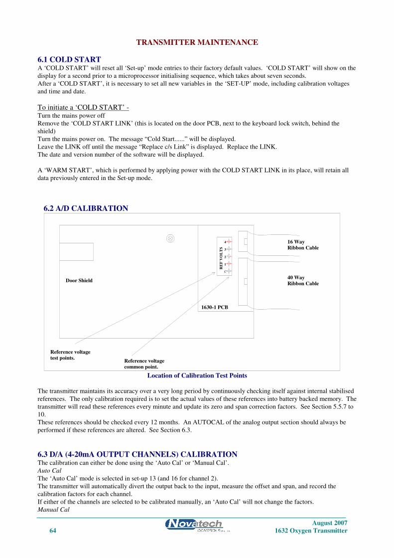
August 2007
64 1632 Oxygen Transmitter
TRANSMITTER MAINTENANCE
6.1 COLD START A ‘COLD START’ will reset all ‘Set-up’ mode entries to their factory default values. ‘COLD START’ will show on the
display for a second prior to a microprocessor initialising sequence, which takes about seven seconds.
After a ‘COLD START’, it is necessary to set all new variables in the ‘SET-UP’ mode, including calibration voltages
and time and date.
To initiate a ‘COLD START’ - Turn the mains power off
Remove the ‘COLD START LINK’ (this is located on the door PCB, next to the keyboard lock switch, behind the
shield)
Turn the mains power on. The message “Cold Start......” will be displayed.
Leave the LINK off until the message “Replace c/s Link” is displayed. Replace the LINK.
The date and version number of the software will be displayed.
A ‘WARM START’, which is performed by applying power with the COLD START LINK in its place, will retain all
data previously entered in the Set-up mode.
Location of Calibration Test Points
The transmitter maintains its accuracy over a very long period by continuously checking itself against internal stabilised
references. The only calibration required is to set the actual values of these references into battery backed memory. The
transmitter will read these references every minute and update its zero and span correction factors. See Section 5.5.7 to
10.
These references should be checked every 12 months. An AUTOCAL of the analog output section should always be
performed if these references are altered. See Section 6.3.
6.3 D/A (4-20mA OUTPUT CHANNELS) CALIBRATION The calibration can either be done using the ‘Auto Cal’ or ‘Manual Cal’.
Auto Cal
The ‘Auto Cal’ mode is selected in set-up 13 (and 16 for channel 2).
The transmitter will automatically divert the output back to the input, measure the offset and span, and record the
calibration factors for each channel.
If either of the channels are selected to be calibrated manually, an ‘Auto Cal’ will not change the factors.
Manual Cal
6.2 A/D CALIBRATION
Ribbon Cable
Ribbon Cable
Reference voltage
Reference voltagetest points.
common point.
Door Shield
RE
F V
OL
TS
1630-1 PCB
1
C
4
3
2
40 Way
16 Way

August 2007
1632 Oxygen Transmitter 65
The ‘Manual Cal’ mode is selected in set-up 13 (and 16).
Set the 4mA calibration first and then the 20mA calibration.
1. Select ‘Set 4mA Trim’ in set-up 13 (or 16).
2. Return to RUN mode.
3. Measure the output on the channel to be calibrated with a digital multimeter. If the current is not exactly 4.00mA,
return to set-up mode and change the 4mA calibration factor in set-up 14 (or 17).
4. Re-measure the current while back in RUN mode until the current is within 3.9 to 4.1mA.
5. Return to set-up mode and select ‘Manual Cal’ in set-up 13 (or 16).
Set the 20mA calibration factor.
6. Select ‘Set 20mA Trim’ in set-up 13 (or 16).
7. Return to RUN mode.
8. Measure the output on the channel to be calibrated with a digital multimeter. If the current is not exactly 20.00mA,
return to set-up mode and change the 20mA calibration factor in set-up 15 (or 18).
9. Re-measure the current while back in RUN mode until the current is within 19.9 to 20.1mA.
10. Return to set-up mode and select ‘Manual Cal’ in set-up 13 (or 16).
This calibration is now saved in battery backed memory until
The factors are changed in the manual calibration
The transmitter is forced into a COLD-START (see section 6.1)
The calibration mode in set-up 13 (or 16) is changed to Auto Cal and an Auto Cal is initiated.
NOTE: The 4mA or the 20mA trim mode will only be held on the output channels for 30 minutes before automatically
returning to ‘Manual Cal’ mode in set-up 13 (or 16).
6.4 PUMP REPLACEMENT The reference air pump is mounted on the 1630-2 PCB in the base of the transmitter. The operation of the pump is
monitored by the transmitter and alarms will be shown if a fault occurs. (“Pump Fail” alarm)
To replace the pump, unplug all the field wiring terminals. ie. Probe connectors, power connector etc.
The nuts for the pump screws are captive into the PCB, enabling the pump to be removed WITHOUT removing the
PCB. The pump wires can be unplugged.
6.5 BACK-UP BATTERY REPLACEMENT The back-up battery is contained within the battery-like real time clock/memory module, plugged into socket M2. It is
rated for an average service life of greater than ten years. The module is not re-chargeable and should be replaced every
three years in a stored transmitter with power off or every eight years with transmitters that have had the power on. The
memory module must be purchased from Novatech Controls or an agent of Novatech Controls.
After replacing the battery, re-enter all set-up mode functions.
6.6 ELECTRONIC REPAIRS Electronic schematics are included in Appendix 5. A competent electronic technician could perform troubleshooting
with these schematics, aided by the transmitter self-diagnostic alarms. It is recommended that service be performed on a
changeover circuit board basis. A fast turn-around or replacement service is available from Novatech or accredited
service agents. Other service aids, including a test EPROM firmware package and probe input simulator are also
available.
There are 3 fuses on the 1630-2 (terminal) PCB. FS1 and FS2 are M205 3Amp (or 3.15Amp) fast blow and are in the
input power active and neutral lines. FS3 is a PCB mounted 375mA fuse and is in series with the power transformer
primary winding.
If any of these fuses are blown the transmitter display will be blank.
6.7 INSTALLING A NEW PROBE OR SENSOR Whenever a new oxygen probe or sensor is installed, the millivolt offset value should be entered. To achieve this refer
to set-up 11 (and 12 for the second sensor).

August 2007
66 1632 Oxygen Transmitter
The probe or sensor offset is noted on a tag or label attached to probe or sensor. To check an offset on site, the probe or
sensor must be sensing air with reference air connected and allowed to settle at the operating temperature for 30
minutes. Read the offset in ‘RUN’ mode in millivolts on the lower line. Offset errors can occur if the sensor does not
have some air passing over it. A gentle flow of air in the calibration check port can be provided by a reference air pump
or similar. If a probe is in a process with the process running, the air purge on the sensing side of the oxygen sensor will
only be successful if the probe has a filter or small sensing hole. Probes with open sensing ends or with large sensing
holes allow the process gas to mix with the calibration gas, giving a false reading.
For heated probes or sensors, if the combustion appliance is not operational and the probe or sensor heater is interlocked
with the ‘FUEL ON’ signal, the ‘BURNER BYPASS’ switch should be set to ‘BYPASS’ to power the probe or sensor
heater after removing the probe or sensor from the flue. For unheated probes, the sensing tip must be raised to at least
650°C (1200°F) with a portable furnace.
CAUTION DANGER
Return the ‘BURNER BYPASS’ switch to normal (off) before installing the probe or sensor in the
flue.
6.8 TEST EQUIPMENT REQUIRED All measurements are simplified if a transmitter is connected to the probe or sensor. Readings can then be easily taken
of probe or sensor impedance, EMF, temperature and percent oxygen. The transmitter also provides proper heater
control for heated probes or sensors.
The following tests are described using readily available workshop equipment where a transmitter is not available. If a
transmitter is available the same test procedures will apply. First check all alarms on the transmitter, allowing time for
the probe or sensor to heat up after switch on.
An instrument to measure probe or sensor EMF and temperature is required. A 3 1/2 or 4 1/2 digit multimeter will
perform both measurements.
A separate temperature indicator to suit the probe or sensor thermocouple type is also useful, although not necessary.
A reference air pump is required and a cylinder of calibration check gas e.g. 2 % oxygen in nitrogen. The cylinder
should have a pressure and flow regulator. Both of these are inexpensive devices available from gas supply companies.
The calibration check gas should be chromatograph tested to an accuracy of 0.1 % oxygen.
TEST EQUIPMENT FOR UNHEATED PROBES
A small test furnace capable of raising the probe tip temperature to over 700°C (1300°F) is required. The furnace
should have a uniform temperature for about 50 mm (2”) either side of the sensor tip.
TEST EQUIPMENT FOR HEATED PROBES OR SENSORS
If a 1632 transmitter is available at the test location then no other equipment will be required. If not, then a controllable
power source for the heater is required. A Variac (variable transformer), set to approximately 80 volts will regulate the
probe or sensor temperature to over 700°C (1300°F).
6.9 TESTING A PROBE OR SENSOR With the probe or sensor heated to over 700°C (1300°F), either from a small test furnace or its own internal heater,
connect a digital multimeter to the probe or sensor electrode conductors. Connect the multimeter positive to the internal
electrode conductor. Connect reference air to and apply a gentle purge of air to the probe calibration check port.
Reference airflow should be 50 to 500 cc/minute (6 to 60 scfm). The multimeter should read zero millivolts + two
millivolts. If not, then there is a problem with the probe electrodes and the sensor needs refurbishing. Normally a faulty
probe electrode is indicated with a high source impedance. 1234 sensors do not require reference air but a gentle flow
of air should be admitted into the sample connection.

August 2007
1632 Oxygen Transmitter 67
To test the source impedance, set the multimeter to read ohms and take a measurement, within a couple of seconds, of
the probe or sensor impendence. Reverse the multimeter and repeat the reading. Take the average of the two readings
for an approximate measurement of impedance. If the impedance is above 10kΩ, then the probe or sensor needs to be
replaced. The probe or sensor must be over 700°C (1300°F) or above for this measurement. The reason that impedance
measurements need to be performed quickly, is that the zirconia sensor polarises with the DC voltage from the
multimeter across it.
If the probe or sensor tests reveal less than 2 mV offset and a good impedance reading, the next step is to apply a
calibration check gas. The calibration check gas should be inserted in the calibration check port. With the calibration
check gas flowing, the probe or sensor should develop an EMF according to the tables in Appendix 2. If the EMF
reading is low then there may be insufficient calibration check gas flow. Increase the calibration check gas until the
reading is correct. An excessive calibration check gas flow will cause cooling on one surface of the sensor, giving
temperature differential errors on the sensor.
As an alternative, using the reference air port, the calibration check gas can be inserted into the inside of a probe sensor.
This requires a lower flow rate, and thus lower usage of calibration check gas. The flow rate should be similar to that of
the reference air, which should be removed for internal calibration check. The probe or sensor EMF reading will be
identical but negative in polarity. A small flow of air should be flowing over the outside of the sensor, when testing in
this way.
Occasionally, a sensor can develop offset with a polluted electrode caused by contaminants in the flue gas stream. In
this case the impedance may be OK but the output incorrect. This phenomenon is rare.
6.10 PROBE OR SENSOR THERMOCOUPLE Although some unheated probes are specified without a thermocouple, most probes, both heated and unheated, have an
integral thermocouple which is fitted in to the four bore insulator. The transmitter has an alarm function that will advise
the operator of an open circuit thermocouple, however bench testing can be performed by simply measuring the
thermocouple continuity.
6.11 HEATER FAILURE For heated probe or sensors, a heater failure will cause a ‘SENSOR UNDER TEMP’ or ‘HEATER FAIL’ alarm.
Heaters can be tested with a continuity test. The heater impedance should be approximately 100Ω. Should the heater be
open or short-circuited, replace the probe or sensor.
6.12 FILTER BLOCKAGE For oxygen probes with filters in installations with entrained solids in the flue gas, it is sometimes necessary to replace
the filter. Filters are normally cleared with back purging. However fine fly ash or other particles can ultimately
completely block a filter necessitating filter replacement. A new probe filter can be fitted

August 2007
68 1632 Oxygen Transmitter

August 2007
1632 Oxygen Transmitter 69
APPENDICES
1. CONSTITUENT VALUES FOR VARIOUS FUELS
2. PROBE OR SENSOR EMF TABLES
3. % OXYGEN SCALE TO LOGARITHMIC
4. SAMPLE LOG PRINT OUT
5. CIRCUIT SCHEMATICS
6. MODBUS™ REGISTER MAP & APPLICATION NOTES

August 2007
70 1632 Oxygen Transmitter

August 2007
1632 Oxygen Transmitter 71
APPENDIX 1
CONSTITUENT VALUES FOR FUELS
If the transmitter is set up to have readout or output of combustibles or maximum carbon dioxide, then the fuel
constituents must be entered. Any or all of the variables can be modified and entered in set-up steps 39 to 45 and 46 to
51. (Refer to Section 5.5). Your fuel supplier or chemist should be able to give you all these values.
A is the heat of combustion of the fuel per gram atom of contained carbon.
H is the H/C atom ratio in the fuel.
O is the O/C atom ratio in the fuel.
N is the N/C atom ratio in the fuel.
S is the S/C atom ratio in the fuel.
M is the ratio of H2O molecules to C atoms in the fuel

August 2007
72 1632 Oxygen Transmitter
FUEL A H O N S M
_____________________________________________________________________________
Blast furnace gas 50.55 0.08 1.30 3.08 b a
Coke oven gas 256.88 5.60 0.25 0.23 b a
Producer gas 101.98 1.18 1.02 2.90 b a
Natural gas 209.90 3.86 0 0.10 0 0
Propane, natural 176.40 2.69 0 0 0 0
Butane, refinery 166.10 2.34 0 0 0 0
Methanol 172.59 3.97 1.00 — — —
Gasoline, motor 157.58 2.01 0 0 0 0
No 1 Distillate oil 149.65 1.83 0 — 0 —
No 2 Distillate oil 145.18 1.71 — — 0 —
No 4 Fuel oil 145.54 1.60 — — 0.01 0
No 5 Residual oil 142.25 1.44 — 0 0 0
No 6 Residual oil 136.52 1.25 0.01 0 0 0
Wood, non-resinous 110.91 2.26 1.07 0 0 c
Coal, bituminous 116.88 0.74 0.05 0 0 0.03
Coal, anthracite 104.98 0.35 0.05 0 0.01 0.04
Coke 99.63 0.11 0.01 0.01 0 0.01
a. The moisture level varies depending on the process details.
The calculated values assume M = O.
b. The sulphur level varies depending on the process details.
The calculated values assume S = O.
c. Variable.
Values calculated from the North American Combustion Handbook, Tables 2.1a and 2.1b.

August 2007
1632 Oxygen Transmitter 73
APPENDIX 2
PROBE OR SENSOR EMF TABLES
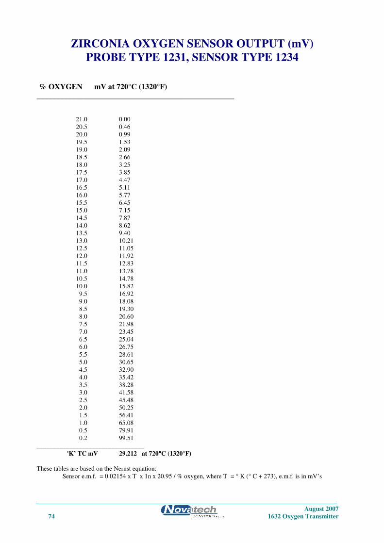
August 2007
74 1632 Oxygen Transmitter
ZIRCONIA OXYGEN SENSOR OUTPUT (mV)
PROBE TYPE 1231, SENSOR TYPE 1234
% OXYGEN mV at 720°C (1320°F)
___________________________________________________
21.0 0.00
20.5 0.46
20.0 0.99
19.5 1.53
19.0 2.09
18.5 2.66
18.0 3.25
17.5 3.85
17.0 4.47
16.5 5.11
16.0 5.77
15.5 6.45
15.0 7.15
14.5 7.87
14.0 8.62
13.5 9.40
13.0 10.21
12.5 11.05
12.0 11.92
11.5 12.83
11.0 13.78
10.5 14.78
10.0 15.82
9.5 16.92
9.0 18.08
8.5 19.30
8.0 20.60
7.5 21.98
7.0 23.45
6.5 25.04
6.0 26.75
5.5 28.61
5.0 30.65
4.5 32.90
4.0 35.42
3.5 38.28
3.0 41.58
2.5 45.48
2.0 50.25
1.5 56.41
1.0 65.08
0.5 79.91
0.2 99.51
_________________________________
'K’ TC mV 29.212 at 720°°°°C (1320°F)
These tables are based on the Nernst equation:
Sensor e.m.f. = 0.02154 x T x 1n x 20.95 / % oxygen, where T = ° K (° C + 273), e.m.f. is in mV’s
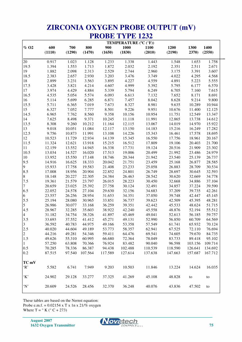
August 2007
1632 Oxygen Transmitter 75
ZIRCONIA OXYGEN PROBE OUTPUT (mV)
PROBE TYPE 1232 TEMPERATURE (ºC (°F))
% O2 600 700 800 900 1000 1100 1200 1300 1400
(1110) (1290) (1470) (1650) (1830) (2010) (2190) 2370) (2550)
_________________________________________________________________ _
20 0.917 1.023 1.128 1.233 1.338 1.443 1.548 1.653 1.758
19.5 1.394 1.553 1.713 1.872 2.032 2.192 2.351 2.511 2.671
19 1.882 2.098 2.313 2.529 2.744 2.960 3.175 3.391 3.607
18.5 2.383 2.657 2.930 3.203 3.476 3.749 4.022 4.295 4.568
18 2.899 3.231 3.563 3.895 4.227 4.559 4.891 5.223 5.555
17.5 3.428 3.821 4.214 4.607 4.999 5.392 5.795 6.177 6.570
17 3.974 4.429 4.884 5.339 5.794 6.249 6.705 7.160 7.615
16.5 4.535 5.054 5.574 6.093 6.613 7.132 7.652 8.171 8.691
16 5.114 5.699 6.285 6.871 7.457 8.042 8.628 9.214 9.800
15.5 5.711 6.365 7.019 7.673 8.327 8.981 9.635 10.289 10.944
15 6.327 7.052 7.777 8.501 9.226 9.951 10.676 11.400 12.125
14.5 6.965 7.762 8.560 9.358 10.156 10.954 11.751 12.549 13.347
14 7.625 8.498 9.371 10.245 11.118 11.991 12.865 13.738 14.612
13.5 8.308 9.260 10.212 11.164 12.115 13.067 14.019 14.970 15.922
13 9.018 10.051 11.084 12.117 13.150 14.183 15.216 16.249 17.282
12.5 9.756 10.873 11.991 13.108 14.226 15.343 16.461 17.578 18.695
12 10.523 11.729 12.934 14.139 15.345 16.550 17.756 18.961 20.167
11.5 11.324 12.621 13.918 15.215 16.512 17.809 19.106 20.403 21.700
11 12.159 13.552 14.945 16.338 17.731 19.124 20.516 21.909 23.302
10.5 13.034 14.527 16.020 17.513 19.006 20.499 21.992 23.486 24.979
10 13.952 15.550 17.148 18.746 20.344 21.942 23.540 25.139 26.737
9.5 14.916 16.625 18.333 20.042 21.751 23.459 25.168 26.877 28.585
9 15.933 17.758 19.583 21.408 23.233 25.058 26.883 28.709 30.534
8.5 17.008 18.956 20.904 22.852 24.801 26.749 28.697 30.645 32.593
8 18.148 20.227 22.305 24.384 26.463 28.542 30.620 32.669 34.778
7.5 19.361 21.579 23.797 26.015 28.223 30.450 32.668 34.886 37.104
7 20.659 23.025 25.392 27.758 30.124 32.491 34.857 37.224 39.590
6.5 22.052 24.578 27.104 29.630 32.156 34.683 37.209 39.735 42.261
6 23.557 26.256 28.954 31.653 34.351 37.050 39.748 42.447 45.145
5.5 25.194 28.080 30.965 33.851 36.737 39.623 42.509 45.395 48.281
5 26.986 30.077 33.168 36.259 39.351 42.442 45.533 48.624 51.715
4.5 28.967 32.285 35.603 38.922 42.240 45.558 48.876 52.194 55.512
4 31.182 34.754 38.326 41.897 45.469 49.041 52.613 56.185 59.757
3.5 33.693 37.552 41.412 45.271 49.131 52.990 56.850 60.709 64.569
3 36.592 40.783 44.975 49.166 53.358 57.549 61.741 65.932 70.124
2.5 40.020 44.604 49.189 53.773 58.357 62.941 67.525 72.110 76.694
2 44.216 49.281 54.346 59.411 64.476 69.541 74.605 79.670 84.735
1.5 49.626 55.310 60.995 66.680 72.364 78.049 83.733 89.418 95.102
1 57.250 63.808 70.366 76.924 83.482 90.040 96.598 103.156 109.714
0.5 70.285 78.336 86.387 94.438 102.488 110.539 118.590 126.641 134.692
0.2 87.515 97.540 107.564 117.589 127.614 137.638 147.663 157.687 167.712
TC mV
‘R’ 5.582 6.741 7.949 9.203 10.503 11.846 13.224 14.624 16.035
‘K’ 24.902 29.128 33.277 37.325 41.269 45.108 48.828 to to
‘N’ 20.609 24.526 28.456 32.370 36.248 40.076 43.836 47.502 to
These tables are based on the Nernst equation:
Probe e.m.f. = 0.02154 x T x 1n x 21/% oxygen
Where T = ° K (° C + 273)

August 2007
76 1632 Oxygen Transmitter
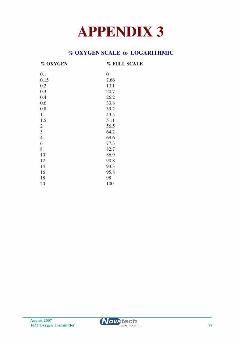
August 2007
1632 Oxygen Transmitter 77
APPENDIX 3
% OXYGEN SCALE to LOGARITHMIC
% OXYGEN % FULL SCALE
0.1 0
0.15 7.66
0.2 13.1
0.3 20.7
0.4 26.2
0.6 33.8
0.8 39.2
1 43.5
1.5 51.1
2 56.5
3 64.2
4 69.6
6 77.3
8 82.7
10 86.9
12 90.8
14 93.3
16 95.8
18 98
20 100

August 2007
78 1632 Oxygen Transmitter

August 2007
1632 Oxygen Transmitter 79
APPENDIX 4
SAMPLE LOG PRINT OUT
Novatech Controls 14-07-2005 06:14:00
Oxygen % 1.86
EMF 1 mV 38.0
Probe Temp 458C (856F)
Ambient T 21.9C (71.42F)
Servc'd 13/07/05
Humidity 43%
Sensor 1 Imp 5.7K
Next Purge at 06:00:00 17-07-2005
Next Print at 06:34:00 14-07-2005
06:00:11 14-07-2005 Heater 1 Fail Is Active
06:00:13 14-07-2005 O2% Low Is Active
02:33:17 14-07-2005 RefPump Fail Accepted

August 2007
80 1632 Oxygen Transmitter

August 2007
1632 Oxygen Transmitter 81
APPENDIX 5
CIRCUIT SCHEMATICS

August 2007
82 1632 Oxygen Transmitter

1
1
2
2
3
3
4
4
5
5
6
6
7
7
8
8
D D
C C
B B
A A
Title
Number RevisionSize
A3
Date: 31/08/2007 Sheet ofFile: \\..\163x-1.prj Drawn By:
Block Diagram1 4
FHC
P5-[0..7]
L4-[3..6]
DAC-PS-[0..5]
P6-[0..7]
P4-[0..7]
D-A2
P3-2
/P6-1
Ser-[1..5]
SVcc
P3-0
VccGnd
Error
SVee
ADCADC.SCH
DAC-PS-[0..5]
P6-[0..7]
P3-[0..7]
/P6-1
Ser-[1..5]
SVcc
SVee
Vcc
Gnd
DACSDACS.SCH
L4-[3..6]
D-A2
P3-[0..7]
P4-[0..7]
P6-[0..7]
P5-[0..7]
P3-2
P3-0
VccGnd
Error
MICROMICRO.SCH
L4-[3..6]
P4-[0..7]
P5-[0..7]
P6-[0..7]
DAC-PS-[0..5] P3-[0..7]
Ser-[1
..5]
SV
cc
Vcc
P3-0
D-A2
P3-2
/P6-1
Gnd
Error
Svee
Novatech Controls
1630-1 1.6 B
Master diagram
SC1 SC2 SC3 SC4 SC5
Mounting holes

August 2007
84 1632 Oxygen Transmitter
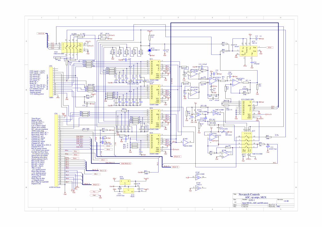
1
1
2
2
3
3
4
4
5
5
6
6
7
7
8
8
D D
C C
B B
A A
Title
Number RevisionSize
A3
Date: 31/08/2007 Sheet ofFile: \\..\Adc.sch Drawn By:
R5410k
R5310k
R52
10k
R56 10k
R511k
R701k8
R68 12K
R6382K5 1%
R69
270k
R71 1k
R671k5
AVcc
Gnd
C18 0.01uF
C190.01uF
AVee
Gnd
C15 0.01uF
X013
X114
X215
X312
X41
X55
X62
X74
INH6
A11
B10
C9
VEE7
X3
VCC16
GND8
IC32 CD4051 SMD
X013
X114
X215
X312
X41
X55
X62
X74
INH6
A11
B10
C9
VEE7
X3
VCC16
GND8
IC30
CD4051 SMD
Gnd
Gnd
Gnd
X013
X114
X215
X312
X41
X55
X62
X74
INH6
A11
B10
C9
VEE7
X3
VCC16
GND8
IC28
CD4051 SMD
X013
X114
X215
X312
X41
X55
X62
X74
INH6
A11
B10
C9
VEE7
X3
VCC16
GND8
IC31
CD4051 SMD
X013
X114
X215
X312
X41
X55
X62
X74
INH6
A11
B10
C9
VEE7
X3
VCC16
GND8
IC29
CD4051 SMD
AVee(5)
AVee(5)
AVee(5)
AVee(5)
AVcc(5)
AVcc(5)
AVcc(5)
AVcc(5)
89
IC18D
74HC04 SMD
P5-[0..7]
014
15
26
12 3
11 1
13
4 10
2
Vcc16
Gnd8
315
Vee90 1 2 3
/En7
IC2274HC4316 SMD
R104 100k
R103 100k
R102 1k
R101 1k
R100 1k
R99 1kR97 100k
R98 100kR96 1k
R95 1kR93 1kR91 1kR89 1k
C331.0/16VTant
C32
0.1
C31
0.1
C30 1.0/16V Tant
C29
0.1
C28
0.1
C27
0.1
C26
0.1
R94 1kR92 1kR90 1k
Gnd
R113
250R
1%
R111
1k5 1
%
R110
9k1 1
%
R108
4k7 1
%
R106
6k
8 1
%
R1052k2
Gnd
AVcc(5)
R606k8 R57
1k
R611kR5810k
AVcc(5)
AVee(5)
Gnd
L4-[3..6]
Gnd
GndAVcc
R88 1k
R86 1kR85 1kR84 1k
R83 1kR82
1kR801k
R78 1k
R871k
R77 1kR79 1kR81
1k
C25
0.1
C22
0.1
C21
0.1
C20
0.1
Gnd
Gnd
C24
0.1
Pro
be
anal
og
in
pu
ts
R45 100k R42
10kGnd
C10
10/16V TantGnd
Gnd
Gnd
Gnd
AVcc(5)
AVee(5)
Gnd
Gnd
AVee(5)
R591k
R66
12k
R65
47k
C16270p npo
Gnd
AVcc
AVee
Gnd
3
21
411
IC26AOPA4234UA
5
67
IC26BOPA4234UA
10
98
IC26C
OPA4234UA
12
1314
IC26DOPA4234UA
O2 sensor #1+
Probe TC +
Aux TC / Sen TC #2 -
CO2 i/p(1637) -
Rear head / RGC TC -
Burner f/b potTrim f/b pot
Heater interlock
+12v analog power
P5-4P5-3P5-2
P5-5
P5-4P5-3P5-2
P5-4P5-3P5-2
P5-4P5-3P5-2
DC volts pre-regulator50/60 mains freq
Heater drive enable
/P6(1) Clock
+5 Digital power
Rear head / RGC TC +
Analog ground
CJ Ambient sensor
R76
100k
AVee(5)
Cal 4-20mA signal
Channel #1 +p/sChannel #1 signalChannel #1 comChannel #2 signalChannel #2 +p/s
Channel #2 com
-12v Analog power
Ref air pump drive (DA-1)
+12v Analog power
Ref air pump current
P4-7
P4-1
R12
250RGnd
P4-3
1 2
714 IC34A
74HC14 SMD 3 4
IC34B
74HC14 SMD
014
15
26
12
3
11
1
13
4
10
2
Vcc
16
Gnd
8
315
Vee
90
12
3
/En
7
IC27
74HC4316 SMD
R75 10k
R74 2k2
R73 220k
R5510k
R62
10k
R50
10k
C23
0.1
C111uF non polar
C1210/16V Tant
R41RH sensor3
21
84
IC24A
OPA2132
5
67
IC24BOPA2132
Vcc
AVee(5)
Gnd
Gnd
GndAVee(5) Vcc
Gnd
Gnd
P5-0P5-1
L4-3
L4-4L4-5L4-6
P4-2DAC-PS-[0..5]
P6(4) Dig o/p data
P6(5) Dig o/p latchAnalog ComP6(6) Dig i/p data
P6(7) Dig i/p load/shiftDigital Com
/P6-1
P6-4
P6-5
P6-6
P6-7
P4-0
GndGnd
VccAVcc
AVee
Input MUX's, ADC and RH sensor2 4
FHC
L4-[3
..6]
P6-[0..7]
P4-[0..7]
D-A2
/P6-1
P6-[0..7]
DAC-PS-[0..5]
DAC-PS-0DAC-PS-1DAC-PS-2DAC-PS-3DAC-PS-4
DAC-PS-5
P3-2
P4-[0..7]
P5-[0
..7]
R1071k
Gnd
C3410/16V Tant
12345678910111213141516171819202122232425262728293031323334353637383940
CN4
40 PIN box header
RS-485 + (Ser4)RS-485 - (Ser3)
RS-232 Tx (Ser2)RS-232 Rx (Ser1)Serial common (Ser5)Watchdog relay drive
CO2 i/p (1637) +
Ser-[1..5]
Ser-1Ser-2Ser-4Ser-3
Ser-5
P4-6
Error
Ext Ref Air Flow Sens
Ser-[1..5]
1213
IC34F74HC14 SMD
Vcc
R64
100k
2.5v
SVcc
SVee
SVcc
SVee
I
C
O
IC3678L05
I
C
O
IC3579L05
C380.1
C370.1
C391.0/16V Tant
Gnd
R7212K
Gnd
+ i/p14
Vo
13
Com
p i
/p10
Vcc
12
- i/p1
Fout7
Com11
Cap
5
Vee
4
IC23VFC-32
Gnd
C14.001uF
+12v Serial coms power
-12v Serial coms power
O2 sensor #1-
Probe TC -Aux TC / Sen TC #2 +
C13 0.1
Gnd
C35 0.1
Gnd
P3-0
Avcc(5)
Avee(5)
AVcc
AVee
Gnd
Vcc
Gnd
Vcc5 6
IC34C74HC14
Gnd
12345678910111213141516
CN5
16PIN
O2 sensor #2+O2 sensor #2-
CO2 signal + (1637)CO2 signal - (1637)
Serial latch o/p enable
C40
0.1
Error
C41
0.1
C42
0.1
C43
0.1
C44
0.1
C45
0.1
C46
0.1
C47
0.1
C48
0.1
Gnd
Gnd
GndC490.1
R115 1k
R116 1k
C50
0.1
C51
0.1
Gnd
Gnd
C520.1
C530.1
Gnd
Gnd
C540.1
Gnd
C55
0.1
Gnd
C56
0.1
C57
0.1Gnd
C58
0.1Gnd
C600.01uF
Gnd
C59
0.1
Gnd
Vcc
R1171k2
R1184k7
Gnd
48
IC33LM336M-2.5
D-A2
VccGnd
Novatech Controls
1630-1 1.6 B
ADC, op amps, MUX

August 2007
86 1632 Oxygen Transmitter

1
1
2
2
3
3
4
4
5
5
6
6
7
7
8
8
D D
C C
B B
A A
Title
Number RevisionSize
A3
Date: 31/08/2007 Sheet ofFile: \\..\Dacs.sch Drawn By:
REFin6
Agn
d5
Vout7
Vdd
8
Din1
CLK2
/CS3
Dout4
IC1MAX538
R24K7
48
IC2LM336M-2.5
R111K
R101K
R91K
R29
220R
R24
22
0R
R23
220R
Vcc
DAC data
DAC cs
48
IC7LM336M-2.5
R510K
R46k8
R301K
R3
10K
C310/16V Tant
Gnd
PWM output
LED1
R1410k
R221K
R81k
R27
47k
R32
470R
R21
1k
R1310k
R19100k
R25
10k
R7
100R
5
67
IC8BLM1458
3
21
84
IC8ALM1458
SVcc(5)
SGnd
SGnd
SGnd
SVee
SVee
SVcc
SGnd
R28
2k2
RX
Tx
I
C
O
IC3LM340L-05
C20.1
C410/25V Tant
R36
470R
R351K
Vcc
Gnd
Gnd
SGnd
SGndSGnd
LED2
123
LK3
RS-485 RS-232
SVcc(5)
R2647k
SVcc(5)
Vcc
SGnd
RS-232 Rx
RS-232 Com
RS-232 TxNet +
Net -
SVcc(5)+12 Isolated
12345678910
CN1
CON-10
RS-232 RxRS-232 TxNetwork -Network +Serial port common
RS-485 Dir
DAC-PS-[0..5]
ClockP6-1
P3-3
P6-2
P6-3
/P6-1
P3-5
P3-7
P3-4
P6-[0..7]
R18
1kSVcc(5)
R11k
Novatech Controls
1630-1 1.6 B
3 4FHC
D-A converters, Serial port
P3-[0..7]
/P6-1
P3-[
0..
7]
P6-[
0..
7]
DAC-PS-0
DAC-PS-1
DAC-PS-2
DAC-PS-3
DAC-PS-4
DAC-PS-5
Ser-1Ser-2
Ser-3Ser-4
Ser-5
Ser-[1..5]Ser-[1..5]
Tx4
TXen3
/RXen2
Rx1
NET-7
NET+6
Vcc
8G
nd
5
IC5SP485CS
TR1BC817
Vcc
R20
27kSVcc
12
LK2
LINK-2
I
C
O
IC4LM340L-05
SGnd
C610/16V Tant
C510/25V TantC1
0.1
SGndSGnd
SVccSVcc(5)
REF6
Gnd
5Vout
7
Vcc
8
Din2
CLK1
/LOAD3
Dout4
IC37LTC1257
DA
C-P
S-[0
..5]
SVcc
SVeeSVee
SVcc
SVee
SGnd
1 2
714
IC6A74HC14
3 4
IC6B74HC14
5 6
IC6C74HC14 89
IC6D
74HC14
1011IC6E
74HC14
1213
IC6F
74HC14
1 2
IC10A74HC04
3 4
IC10B
74HC04
56
IC10C
74HC04
89
IC10D
74HC04
1011
IC10E74HC04
1213
IC10F74HC04
D1BAV99
1
3
4
5
6
OP4PC-400
1
3
4
5
6
OP7PC-400
1
3
4
5
6
OP6PC-400
1
3
4
56
OP5PC-400
SVcc(5)
SVcc(5)
Vcc
1
3
4
5
6
OP3PC-400
1
3
4
5
6
OP2PC-400
1
3
4
5
6
OP1PC-400
R119
470
Gnd
Vcc
Gnd
Vcc

August 2007
88 1632 Oxygen Transmitter

1
1
2
2
3
3
4
4
5
5
6
6
7
7
8
8
D D
C C
B B
A A
Title
Number RevisionSize
A3
Date: 31/08/2007 Sheet ofFile: \\..\Micro.sch Drawn By:
1234
56
1112
8IC16
74HC30 SMD
5 6
IC18C
74HC04 SMD
1213
IC18F74HC04
12
IC18A
74HC04 SMD
8
910
IC15C
74HC02 SMD
12
3IC15A
74HC02 SMD
D03
Q02
D14
Q15
D27
Q26
D38
Q39
D413
Q412
D514
Q515
D617
Q616
D718
Q719
OE1
CLK11
IC20
74HC374 SMD
D03
Q02
D14
Q15
D27
Q26
D38
Q39
D413
Q412
D514
Q515
D617
Q616
D718
Q719
OE1
CLK11
IC14
74HC374 SMD
D03
Q02
D14
Q15
D27
Q26
D38
Q39
D413
Q412
D514
Q515
D617
Q616
D718
Q719
OE1
LE11
IC25
74HC373 SMD
LGnd1
Vcc2
V13
RSel4
R/W5
E6
LD07
LD18
LD29
LD310
LD411
LD512
LD613
LD714
LE
D+
16
LE
D-
15
Gnd30
Gnd31
Gnd32
Gnd33
LCD1LCD-LM16A21
A010
A19
A28
A37
A46
A55
A64
A73
A825
A924
A1021
A1123
A122
A1326
A1427
A151
/CS20
OE/VPP22
DO11
D112
D213
D315
D416
D517
D618
D719
IC12
27C512
A010
A19
A28
A37
A46
A55
A64
A73
A825
A924
A1021
A1123
A122
A1326
A141
/CS20
/OE22
DO11
DI12
D213
D315
D416
D517
D618
D719
R/W27
IC13
HM62256 WIDE SMD
D0D1D2D3D4D5D6D7
A14
B13
E15
Y012
Y111
Y210
Y39
IC17B
74HC139 SMD
A2
B3
E1
Y04
Y15
Y26
Y37
IC17A
74HC139 SMD
A2
B3
E1
Y04
Y15
Y26
Y37
IC19A 74HC139 SMD
A14
B13
E15
Y012
Y111
Y210
Y39
IC19B 74HC139 SMD
R44 47K
Gnd
Gnd
VccGnd
SIP410K 9 PIN
Vcc
TR2BC817
R311K
D0D1D2D3D4D5D6D7
A14
A15
A14
A13
A12
A11A10A9A8
A7
A B
A6A5
A3A4
Gnd 45
6 IC15B
74HC02 SMD
2
Vcc
8 3
Vss
4
Clk7
Sw-in1
o/p6
IC21TC1232COA
R4910k
Vcc
Gnd
Rese
t
LCD-R/W
Gnd
Vcc
Latch 4
Latch 1
A0LCD-R/W
D0D1
D2
D3
D4
D5
D6
D7
D0D1
D2
D3
D4
D5
D6
D7
D0D1
D2
D3
D4
D5
D6
D7
D0D1D2D3D4D5D6D7
A0A1A2A3A4A5A6A7A8A9A10A11A12A13A14A15
R/WPH
Vcc
Vcc
Gnd
135791113151719
2468
101214161820
CN2
20 PIN (pin header)
D1D2D3D4D5D6D7A4A5
A2A3A1A0/PHR/WD0
Vcc
Gnd
SIP
147k
Vcc
PH
/PH
A0A1A2A3A4A5
A7A8A9A10A11A12A13A14A15
A6
A0A1A2A3A4A5
A7A8A9A10A11A12A13A14
A6
R/W
P3-0P3-1P3-2P3-3P3-4P3-5P3-6P3-7
P4-1
P4-3P4-4P4-5
P4-7
P5-0P5-1P5-2P5-3P5-4P5-5P5-6P5-7
P6-0P6-1P6-2P6-3P6-4P6-5P6-6P6-7
4 8
IC9LM336M-2.5
R162K2
Gnd
Vcc
R40
1M
XL1 10.0Mhz low profile
C96p8
C76p8
Gnd1 2 3
LK4
12
LK5
Cold start Link
1FF0
1FC0
1F
80-1
FF
F
TR4BC817
TR3BC817
R384k7
R374k7
Gnd
P5-6
L4-[3..6]
L4-3
L4-4
L4-5
L4-6P4-0
P4-2
P4-4
P3-1
P3-2
P3-6
Gnd
Vcc
+
M1DS1994Gnd
Microprocessor, display and keyboard4 4
FHC
/WR20
SYNC23
RESETout24
D-A167
D-A266
P3(0) EV13
P3(1) EV22
P3(2) EV379
P3(3) PWMout78
P3(4) RxD77
P3(5) TxD76
P3(6) Sclk75
P3(7) Srdy74
P4(0) AN065
P4(1) AN164
P4(2) AN263
P4(3) AN362
P4(4) AN461
P4(5) AN560
P4(6) AN659
P4(7) AN758
DA-Vref68
P5(0)11
P5(1)10
P5(2)9
P5(3)8
P5(4)7
P5(5)6
P5(6)5
P5(7)4
AD-Vref69
Xin28
Xout29
/RD21
/RESET26
P6(7)12
P6(6)13
P6(5)14
P6(4)15
P6(3)16
INT3 P6(2)17
D733
D634
D535
D436
D337
D238
D139
D040
PH31
R/W22
A1542
A1443
A1344
A1245
A1146
A1047
A948
A849
A750
A651
A552
A453
Vcc
72
CN
25
A-V
cc71
AV
ss70
Vss
32
Vss
73
INT2 P6(1)18
INT0 P6(0)19
A354
A255
A156
A057
IC11M37451S4FP SMD
L4-[
3..
6]
D-A2
P3-[0..7]
P4-[0..7]
P5-[0..7]
P6-[0..7]
P3-[0..7]
P4-[0..7]
P5-[0..7]
P6-[0..7]
SIP21k
12
LK12x1 pin link P
3-0
P6-0
P5-[0..7]P5-[0..7]
P3-2
R/W
PH
8 9
IC34D
74HC04
10 11
IC34E
74HC04
R1122M2
R114100K
C361.0/16V Tant
Gnd
Error
Power/reset LED
11
1213
IC15D
74HC02 SMD
123
LK6
3x1 pin link
A0
W/dog
A0
R109
1k
SW7SW9
SW3
SW8SW6
SW4SW2
Gnd
R391k
R43
1k
R46
1k
LED7
LED6
LED5
Gnd
LED8
Vcc
A[0..15]
LED4 LED3
R341k
R331k
Vcc
R48
1M
R471M
Gnd
Gnd
C8
10/16V Tant
Gnd
AlarmAutocal
Display
Purge
Setup mode
Cal check #2
Neutral
Cal check #1
R6
10kVcc
SIP
347K
Vcc D0D1D2D3
D4D5D6D7
A6
C17100p
Gnd
R174k7
Vcc
1011
IC18E
74HC04 SMD
34
IC18B
74HC04 SMD
SW5
P3-0
INC DEC
P4-5
SW1Gnd
Keyboard Lock
R15
10k
Vcc
Vcc
Vcc
1 2 3 4 5 6 7 8
CN3CON-PH3.8-8
Gnd Vcc
External Keypad/LED's
Alarm
Setup
Neutral
P4-6
Gnd
Gnd
Gnd
Error
Vcc
Gnd
D3BAV99
D2BAV99
Gnd
P5-7
Gnd
Vcc
C61
0.1
Gnd
C62
0.1Vcc
1 2
LK7
2x1 pin link
Gnd
D-A2
Novatech Controls
1630-1 1.6 B
Microprocessor

August 2007
90 1632 Oxygen Transmitter
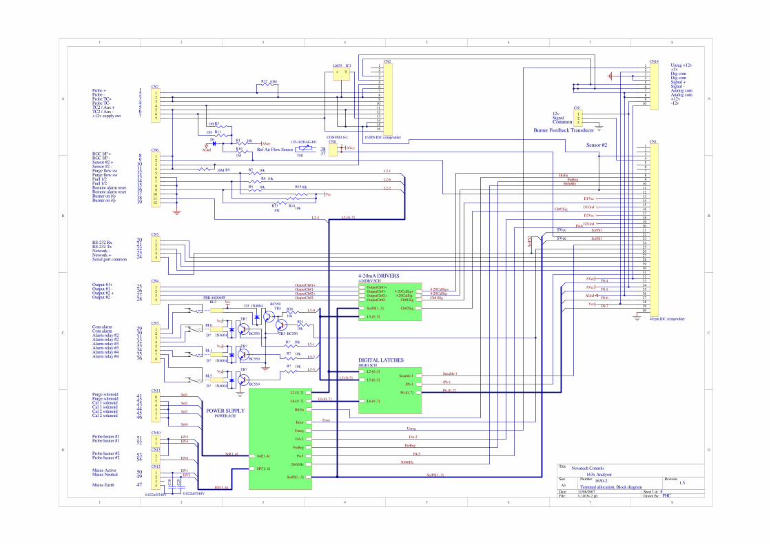
1
1
2
2
3
3
4
4
5
5
6
6
7
7
8
8
D D
C C
B B
A A
Title
Number RevisionSize
A3
Date: 31/08/2007 Sheet ofFile: \\..\163x-2.prj Drawn By:
Novatech Controls
1630-2
Terminal allocation, Block diagram1.5
1 4FHC
163x Analyser
Probe +Probe -Probe TC+Probe TC-TC2 / Aux +TC2 / Aux -
Output #1+
Output #2 +Output #2 -
Output #1 -
Purge flow swPurge flow swFuel 1/2
Com alarmCom alarm
Alarm relay #2Alarm relay #2
Purge solenoidPurge solenoidCal 1 solenoid
Cal 2 solenoid
Probe heater #1Probe heater #1
Mains ActiveMains Neutral
Mains Earth
Fuel 1/2
Cal 1 solenoidCal 2 solenoid
Burner on i/pBurner on i/p
+12v supply out
RGC I/P +RGC I/P -Sensor #2 +Sensor #2 -
Remote alarm resetRemote alarm reset
RS-232 RxRS-232 TxNetwork -Network +Serial port common
Alarm relay #3Alarm relay #3Alarm relay #4Alarm relay #4
T+
-
IC1LM35
TR4BC550
TR3 BC550
D3 1N4004Vcc
123456789
10111213141516171819202122232425262728293031323334353637383940
CN1
40 pin IDC crimp/solderR31
10k
R38
10k
R1510k
R7 10k
R5 10k
R6 10k
R1410k
R13
10k
Vcc
L5-[0..5]
L6-[0..7]
L2-[0..3]
P6-[0..7]
/P6-1
Senable-1
DIGITAL LATCHESDIGIO.SCH
OutputCh#1+OutputCh#1-OutputCh#2+OutputCh#2-
4-20CalSig+
Ch#1Sig
Ch#2Sig
L5-[0..5]
SerPS[1..3]
4-20CalSig-
4-20mA DRIVERS4-20DRV.SCH
4-20CalSig+
PreReg
50/60Hz
P6-7
P6-6
P6-4
/P6-1
P6-5
P4-6
Vcc
AGnd
AVcc
AVee
D1Vcc
D1Gnd
D2Vcc
D2Gnd
50/60HzHV[1..6]
Sol[1..4]
L2-[0..7]
HtrEn
L6-[0..7]
DA-2
P4-5
PreReg
SerPS[1..3]
Unreg
Error
POWER SUPPLYPOWER.SCH
L2-1
L2-6
L2-2
L2-[0..7]
L5-[0..5]
Sol1
Sol2
Sol3
HV4HV5
HV1HV2
Ref Air Flow Sensor
L2-4
P6-[0..7]
L6-[0..7]
Sol[1..4]
HV[1..6]
1234567
CN7
123456789
101112
CN6
12345
CN5
1234
CN4
12345678
CN3
123456
CN11
12
CN10
1234
CN12
TH1
135-102DAG-J01
RL2FBR-46D005P
RL6
RL1
RL5
OutputCh#1+OutputCh#1-OutputCh#2+OutputCh#2-
L5-0
L5-1
L5-2
L5-3
HtrEn
DA-2
PreReg
P4-5
50/60Hz
Ch#1Sig
Ch#2Sig
R31M
R10
1M
R111M
12
CN8CON-PH3.8-2
3738 AVcc
Sensor #2AVee
1234567
89
10111213141516171819
2021222324
25262728
2930313233343536
414243444546
5049
47
5152
Sol4
SerPS[1..3]
SerPS1
Ser
PS
2
SerPS3SVcc
SVee
D1 R1 10k
AGnd
R12 10M
4-20CalSig-
R910M
123456789
10111213141516
CN2
16 PIN IDC crimp/solder
123456789
10
CN14Unreg +12v+5vDig comDig comSignal +Signal -Analog comAnalog com+12v-12v
Unreg
Senable-1
Probe heater #2Probe heater #2
12
CN15
5354 HV6
C29
0.022uF/240V
C30
0.022uF/240V
Error
TR?
BC550
TR?
BC550
TR?
BC550
D? 1N4004
D? 1N4004
D? 1N4004
R? 10k
R? 10k
R? 10k
Vcc
Vcc
Vcc
123
CN?
12vSignalCommon
Burner Feedback Transducer

August 2007
92 1632 Oxygen Transmitter

1
1
2
2
3
3
4
4
5
5
6
6
7
7
8
8
D D
C C
B B
A A
Title
Number RevisionSize
A3
Date: 31/08/2007 Sheet ofFile: \\..\4-20drv.sch Drawn By:
Novatech Controls
1630-2
4-20mA Output Drivers1.5
3 4FHC
163x Analyser
R19
100R
5
67
IC6B
LM358
R23220K
R20220K R26
220K
R39220K
LED23mm LED
R17
100R
5
67
IC5BLM358
R22 220K
R18 220K R25 220K
R32
1M
LED1
3mm LED
3
21
84
IC6A
LM358
3
21
84
IC5A
LM358
Ch#1 +12
Ch#1 -12
Ch#1 sig
Ch#1 com
D1Vcc
D1Gnd
D1Vee
Ch#2 +12Ch#2 Com
Ch#2 -12
Ch#2 sig
D2Vee
D2Vcc
D2Gnd
OutputCh#1+OutputCh#1-
OutputCh#2+OutputCh#2-
4-20CalSig+
Ch#1SigCh#2Sig
L5-4
L5-5
L5-[0..7]
RL4
FBR-46D005P
RL3
FBR-46D005P
TR2BD139
TR1BD139
L5-[0..7]
4-20CalSig+
OutputCh#1+OutputCh#1-OutputCh#2+
OutputCh#2-
Ch#2SigCh#1Sig R34
1M
R33 220K
D1Gnd
D2Gnd
R4
47R
C7
0.1uF
C60.1uF
4-20CalSig-4-20CalSig-

August 2007
94 1632 Oxygen Transmitter

1
1
2
2
3
3
4
4
5
5
6
6
7
7
8
8
D D
C C
B B
A A
Title
Number RevisionSize
A3
Date: 31/08/2007 Sheet ofFile: \\..\Digio.sch Drawn By:
SE
R14
SR
CL
K11
SR
CL
R10
RC
LK
12
E13
O0
15
O1
1
O2
2
O3
3
O4
4
O5
5
O6
6
O7
7
Q7
9
IC2
74
HC
595
SE
R14
SR
CL
K11
SR
CL
R10
RC
LK
12
E13
O0
15
O1
1
O2
2
O3
3
O4
4
O5
5
O6
6
O7
7
Q7
9
IC7
74H
C595
Vcc
Vcc
SER10
P011
P112
P213
P314
P43
P54
P65
P76
CLK12
CLK215
PL1
Q79
Q77
IC374HC165
Digital output data
Clock
Digital output latch
Digital input data
Digital input load/shift
L5-0
L5-1
L5-2
L5-3
L5-4
L5-5
L6-0
L6-1
L5-[0..5]L6-[0..7]
L2-0L2-1
L2-3L2-4L2-5L2-6L2-7
L2-[0..7]
Remote furnace stop
Purge Flow Switch/ Rem burn out
Fuel 1 or 2 input
Burner Bypass SwitchBurner on Relay
Terminal PCB select
Remote Alarm Reset
Mains vlotage selector switch
P6-4
P6-5
P6-6
P6-[0..7]
SIP110k
Vcc
Notatech Controls
1630-2
Digital input/output1.5
2 4FHC
163x Analyser
P6-7
L6-2
L6-3
L2-2
/P6-1
L5-[0..5]L6-[0..7]
L2-[0..7]
P6-[
0..
7]
Latch #2
12LK2
LINK2X1
/P6-1
Ala
rm r
ela
y #
1A
larm
rela
y #
2A
larm
rela
y #
3A
larm
rela
y #
44-2
0 C
al
rela
y #
14-2
0 C
al
rela
y #
2In
c t
rim
rela
yD
ec t
rim
rela
y
Heate
r #1
Purg
e s
ole
noid
Gas
cal
sole
noid
#1
Gas
cal
sole
noid
#2
SIP
210K
Vcc C5
0.1uF
C20.1uF
C40.01uF
Latc
h #
5
Latc
h #
6
Senable-1
Heate
r #2
L6-4
R4510k
Vcc
Senable-1
L6-5

August 2007
96 1632 Oxygen Transmitter

1
1
2
2
3
3
4
4
5
5
6
6
7
7
8
8
D D
C C
B B
A A
Title
Number RevisionSize
A3
Date: 31/08/2007 Sheet ofFile: \\..\Power.sch Drawn By:
Novatech Controls
1630-2
Power Supply, Reference air pump1.6
4 4FHC
BR3
W04 1A bridge rect
C14
2200uF
/25v R
B,
0.3
"
C13
470uF/16v
/En
5
Gnd
3
Vout2
Vin1
F/B4
IC12LM2575T-5.0, small heatsink
D4
SR104 Schotky diode
L1
PE 92114 330uH
C20
220uF/35vC9
1.0uF Tant
12v
+5v 330mA
-12v
C21
220uF/35vC110.1uF
BR2
W04 1A bridge rect
C26
220uF/35vC10
1.0uF Tant
C27
220uF/35v
C120.1uF
BR4
W04 1A bridge rect
C19
220uF/35vC15
1.0uF Tant
C25
220uF/35v
C170.1uF
BR1
W04 1A bridge rect
1
2
11
3
8
7
12
10
16
18
13
15
14
17
TF1
SD-926c
TR6
BC550R43
10k
R42 1k
50/60Hz
Out
Out3
In1
In2
FL1
PLAM 2321 R9FS1
FS2
Vcc
HV[1..6]
Sol[1..4]
Sol1
Sol2
Sol3
L2-[0..7]
L2-3
L2-4
HtrEn
L6-[0..7]
L6-1
L6-2
L6-3
+in1
-in2
-out3
com-out4
+out5
PS1
HPR-104 (5 to +/-12v)
TR5BD140
R27
1ohm
R24 12kR16 10k
3
21
84
IC4A
LM358
5
67
IC4BLM358 R29
150
DA-2
40 Ref air pump -39 Ref air pump +
R21
5k6
R281k
P4-6
163x Analyser
Mains E
L2-0
HV1
HV2
HV3
HV4
HV5
Heater com
Heater 1
Mains N
Mains A
Vcc
AVee
AGnd
AVcc
D1Vcc
D1Vee
D1Gnd
D2Vee
D2VccD2Gnd
-12v
+12vDAC 2 Com
PreReg
12v/300
15v/30
15v/30
15v/30
15
v/3
0
15v/50
15v/50
240v
110v
C8
10/35v Elect
R30 680
C310uF/16v RB
L6-0
C1
0.1uF
12
CN9
AA
KK
22
11
SSR4
S202-S02
AA
KK
22
11
SSR3
S202-S02
AA
KK
22
11
SSR2
S202-S02
AA
KK
22
11
SSR1
S202-S02
I
C
O
IC878L12
I
C
O
IC1079L12
I
C
O
IC978L12
I
C
O
IC1179L12
I
C
O
IC1378L12
I
C
O
IC1479L12
SW3
V202-12-MS-02-Q
RL7
SW1
R401k
LED3Burner on LED
Burner Bypass switch
SW2
POWER ON
LED4Heater #1 On
C22 0.022uF
C18 0.022uF
C16 0.022uF
HV
[1..
6]
Sol[
1..
4]
L6-[0
..7]
L2-[0
..7]
50/60Hz
PreReg
P4-6
DA-2
HtrEn
R37220R
R36
220R
R35
220R
R41220R
LED7
LED6
LED5
C280.022uF
Sol4
D5
1N4004
SerPS1
SerPS2
SerPS3
Ser
PS
[1..
3]
SerPS[1..3]
C24
0.022uF
C230.022uF
12345
CN13
AA
KK
22
11
SSR5
S202-S02
HV6
Heater 2
R44220R
L6-4
LED8Heater #2 On
0-2.5v
0-5v
Unreg
FS3
250mA axial lead fuse
Unreg
TR11BC560
R48
10k
R5010k
TR
10
BC
560
R4910k
R5110k
R47 10k
TR12BC550
Error
L6-5
Error
Vcc
R56 10k
C331.0uF

August 2007
98 1632 Oxygen Transmitter

August 2007
1632 Oxygen Transmitter 99
APPENDIX 6
MODBUS™ Register Map and Application Notes
MODBUS™ Functions Supported are:-
ReadHolding Register Function 3
WriteHolding Register Function 6 ( for allowable addresses only )
Introduction.
The 1632 transmitter implements the MODBUS™ slave protocol, it is intended to work in conjunction with a
MODBUS™ master.
This is accomplished by setting the MODBUS™ address to some non-zero value in the range 1-31, setting the jumper
positions to select the RS485 half duplex configuration, and re-starting the transmitter.
The master must be configured as follows.
Baud Rate 9600
Parity none
Stop Bits 1
RS485 Half Duplex
Mode RTU ( binary mode)
A typical transaction would be to read the current value of a variable from the transmitter.
The master send a ReadHoldingRegister packet, with the appropriate address and the transmitter responds with data at
that address.
The Register Addresses are as follows, to convert to Schneider addresses for earlier model PLC's address space, add
40001 to each address.
or for later model PLC's with linear address space the address co-responds directly to %MW XXXX address.
For Example, to read probe temperature set-point -
Read %MW1436 which is equivalent to holding register 41437 = 40001 + 1436
Some data is 32 bit data (double) which requires some care to ensure that the word order is correctly interpreted.
For Example, OXYGEN32, (dual probe) which is at address 2052 is interpreted as follows.
2052 contains the high 16 bits for probe 1 oxygen
2053 contains the low 16 bits for probe 1 oxygen
2054 contains the high 16 bits for probe 2 oxygen
2055 contains the low 16 bits for probe 2 oxygen

August 2007
100 1632 Oxygen Transmitter
Configuration and Setup Addresses
Holding
Reg. Function Description
716 Probe #1 offset 10 = 1.0mV
717 Probe #2 offset 10 = 1.0mV
Purge control related variables
754 Purge enable 0= off, 1= on
Calibration checking gas related variables
759 Gas calibration check 0= off, 1= 1 gas, 2= 2 gasses
2048 Probe #1 EMF 100,000 = 100.000 mV
2050 Probe #2 EMF 100,000 = 100.000 mV
2052 Probe #1 OXYGEN 100,000,000 = 100.0%
2054 Probe #2 OXYGEN 100,000,000 = 100.0%
2056 Probe #1, Impedance 1,000 = 1 k Ω
2058 Probe #2, Impedance 1,000 = 1 k Ω
2060 Probe #1 TC mV 100,000 = 100.000 mV
2062 Probe #2 TC mV 100,000 = 100.000 mV
2064 Probe #1 temperature 700 = 700 degC
2066 Probe #2 temperature 700 = 700 degC
2068 ALRM-ARRAY Array of current alarm status. See below
2084 ALRM-TIMES Array of timestamp of alarms
Alarm array order -
1. Heater 1 fail 2. Sensor1 fail (Impedance too high) 3. Probe 1 filter blocked 4. Probe 1 thermocouple open circuit 5. Reference air Pump fail 6. Battery backed RAM fail 7. Mains frequency measurement fail 8. ADC warning (outside normal specifications, but still accurate) 9. DAC warning (outside normal specifications, but still accurate) 10.Oxygen % low
11.Oxygen % high
12.Oxygen % very Low
13.Oxygen % deviation too high between oxygen probes
14.Oxygen % Deficient (oxygen % low on oxygen deficient range)
15.ADC Calibration fail
16.Gas 1 calibration error
17.Gas 2 calibration error
18.Burner bypass switch on
19.Aux thermocouple open circuit
20.Reference air pump fail
21.DAC Calibration fail
22.Probe Calibration
23.Heater 2 Fail
24.Sensor 2 Fail (Impedance too high)
25.Prbe2 thermocouple open circuit
26.Probe temperature below 650 °C
27.Gas calibration check in Progress
28.Probe Purging
29.Alarm horn
30.Probe Temperature high

August 2007
1632 Oxygen Transmitter 101
INDEX 1230 Oxygen probes 9
1231 Heated oxygen probe 9
1234 Oxygen sensor installing 24
4-20 mA calibration 48
Alarms
High oxygen 56
Low oxygen 56
Very low oxygen 57
Alarm button 39
Alarm relays 41
Alarm schedule 39
Alarms 29, 33
Common alarm 39
Selectable alarms 40
Summary 39
Analyser mounting 22
Analyser 17
Analyser description 6
Analyser system 6
Auxiliary temperature 19
backlight 41
Back-up battery 20
Battery 20
Battery replacement 65
Baud rate 58
Burner by-pass switch 41
Burner by-pass switch 33
Calender 47
Calibration
A/D 64
Checking of probes 19
Electronics 18
Probes 18
Sensor 33
Test points 64
Calibration
D/A 64
Calibration check connecting calibration solenoid 30
Calibration checking 90
Calibration gas check 34
Calibration gases 55
Centigrade 51
Cold start 64
Commissioning 33
Common Alarms 29
Damping Factor 59, 60
Damping factor 60, 61
Display button 38
Dual fuel 53
Dual fuel input connecting 31, 35
Dust in the flue gas 34
Fahrenheit 51
Filter Blockage 67
Filter purge pressure switch 14
Filter purging 34
Function select 46
Heater failure 67
Heater interlock relays 27
Impedance 17
Interlock 27
Lower Line 7
Lower line display functions 52
Model 1232 unheated oxygen probe 9
Model 1234 oxygen sensor 10
Number of sensors 47
Option or value 46
Outputs 7
Oxygen deviation oxygen deviation 57
Oxygen probe installing 22
Oxygen probe 12
Power 33
Power lamp 41
Pressure 17, 52, 53
Print log data 58
Printer connecting 31, 32
Probe testing 66
Probe cable 28
Pump replacement 65
Purge 19
Automatic 54
Connecting purge solenoid 30
Freeze time 55
Purge / Cal time 54
Range of Indication 7
Range of output 1 7
Range of output 2 7
Reference air connecting 31
Reference air selection 59
Reference voltage 47
Relative humidity 59
Repairs 65
RH 59
RS 232 19
RS 485 19
Run mode 33
Sensor type 49
Serial port 31, 32
Service date 49
Set-up & run modes 46
Set-up function details 47
Set-up mode 33
Set-Up Mode Functions 44
software 3
Specifications 5, 12
Stratification 34
Technical Enquires 3
Testing A Probe 66
Thermocouple type probe 49
Thermocouple type auxiluary 50
Time 47
Top line units 51
Transmitter 4-20 mA 50

August 2007
102 1632 Oxygen Transmitter
Version, software 3
Watchdog timer 20
Zirconia sensor 16
Zirconia sensor output 74
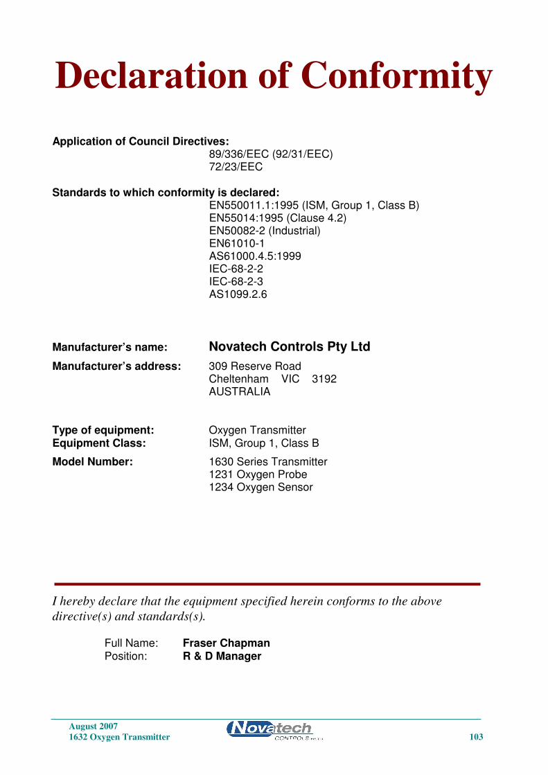
August 2007
1632 Oxygen Transmitter 103
Declaration of Conformity Application of Council Directives: 89/336/EEC (92/31/EEC) 72/23/EEC Standards to which conformity is declared: EN550011.1:1995 (ISM, Group 1, Class B) EN55014:1995 (Clause 4.2) EN50082-2 (Industrial) EN61010-1 AS61000.4.5:1999 IEC-68-2-2 IEC-68-2-3 AS1099.2.6
Manufacturer’s name: Novatech Controls Pty Ltd
Manufacturer’s address: 309 Reserve Road Cheltenham VIC 3192 AUSTRALIA Type of equipment: Oxygen Transmitter Equipment Class: ISM, Group 1, Class B
Model Number: 1630 Series Transmitter 1231 Oxygen Probe 1234 Oxygen Sensor
I hereby declare that the equipment specified herein conforms to the above
directive(s) and standards(s). Full Name: Fraser Chapman Position: R & D Manager

August 2007
104 1632 Oxygen Transmitter
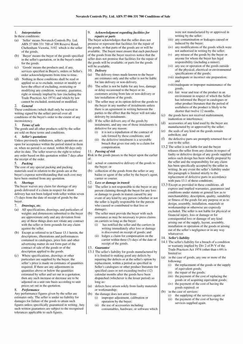
Novatech Controls Pty. Ltd. ABN 57 006 331 700 Conditions of Sale
1. Interpretation In these conditions:
(a) `Seller' means Novatech Controls Pty. Ltd.
ABN 57 006 331 700 of 309 Reserve Road,
Cheltenham Victoria, 3192 which is the seller
of the goods.
(b) `Buyer' means the buyer of the goods specified
in the seller's quotation, or in the buyer's order
for the goods.
(c) `Goods' means the products and, if any,
services specified in Buyer's, orders or Seller's
order acknowledgments from time to time.
(d) Nothing in these conditions shall be read or
applied so as to exclude, restrict or modify or
have the effect of excluding, restricting or
modifying any condition, warranty, guarantee,
right or remedy implied by law (including the
Trade Practices Act 1974) and which by law
cannot be excluded, restricted or modified.
2. General These conditions (which shall only be waived in
writing signed by the seller) prevail over all
conditions of the buyer's order to the extent of any
inconsistency.
3. Terms of sale The goods and all other products sold by the seller
are sold on these terms and conditions.
4. Seller's quotations Unless previously withdrawn, seller's quotations are
open for acceptance within the period stated in them
or, when no period is so stated, within 60 days only
after its date. The seller reserves the right to refuse
any order based on this quotation within 7 days after
the receipt of the order.
5. Packing The cost of any special packing and packing
materials used in relation to the goods are at the
buyer's expense notwithstanding that such cost may
have been omitted from any quotation.
6. Shortage The buyer waives any claim for shortage of any
goods delivered if a claim in respect for short
delivery has not been lodged with seller within seven
(7) days from the date of receipt of goods by the
buyer.
7. Drawings, etc.
(a) All specifications, drawings, and particulars of
weights and dimensions submitted to the buyer
are approximate only and any deviation from
any of these things does not vitiate any contract
with the seller or form grounds for any claim
against the seller.
(b) Except as referred to in Clause 13.1 herein, the
descriptions, illustrations and performances
contained in catalogues, price lists and other
advertising matter do not form part of the
contract of sale of the goods or of the
description applied to the goods.
(c) Where specifications, drawings or other
particulars are supplied by the buyer, the
seller’s price is made on estimates of quantities
required. If there are any adjustments in
quantities above or below the quantities
estimated by seller and set out in a quotation,
then any such increase or decrease are to be
adjusted on a unit rate basis according to unit
prices set out in the quotation.
8. Performance Any performance figures given by the seller are
estimates only. The seller is under no liability for
damages for failure of the goods to attain such
figures unless specifically guaranteed in writing. Any
such written guarantees are subject to the recognised
tolerances applicable to such figures.
9. Acknowledgment regarding facilities for
repairs or parts The buyer acknowledges that the seller does not
promise or represent that facilities for the repair of
the goods, or that parts of the goods are or will be
available. The buyer must ensure that each purchaser
of the goods from the buyer receives notice that the
seller does not promise that facilities for the repair of
the goods will be available; or parts for the goods
will be available.
10. Delivery
(a) The delivery times made known to the buyer
are estimates only and the seller is not be liable
for late delivery or non-delivery.
(b) The seller is not be liable for any loss, damage
or delay occasioned to the buyer or its
customers arising from late or non-delivery or
late installation of the goods.
(c) The seller may at its option deliver the goods to
the buyer in any number of instalments unless
there is an agreement in writing between the
parties to the effect that the buyer will not take
delivery by instalments.
(d) If the seller delivers any of the goods by
instalments, and any one of those instalments is
defective for any reason:
(i) it is not a repudiation of the contract of
sale formed by these conditions; and
(ii) the defective instalment is a severable
breach that gives rise only to a claim for
compensation.
11. Passing of risk Risk in the goods passes to the buyer upon the earlier
of:
(a) actual or constructive delivery of the goods to
the buyer; or
(b) collection of the goods from the seller or any
bailee or agent of the seller by the buyer's agent,
carrier or courier.
12. Loss or damage in transit
(a) The seller is not responsible to the buyer or any
person claiming through the buyer for any loss
or damage to goods in transit caused by any
event of any kind by any person (whether or not
the seller is legally responsible for the person
who caused or contributed to that loss or
damage).
(b) The seller must provide the buyer with such
assistance as may be necessary to press claims
on carriers so long as the buyer:
(i) has notified the seller and the carriers in
writing immediately after loss or damage
is discovered on receipt of goods; and
(ii) lodges a claim for compensation on the
carrier within three (3) days of the date of
receipt of the goods.
13. Guarantee
13.1 The seller's liability for goods manufactured by
it is limited to making good any defects by
repairing the defects or at the seller's option by
replacement, within a period as specified in
Seller's catalogues or other product literature for
specified cases or not exceeding twelve (12)
calendar months after the goods have been
dispatched (whichever is the lesser period) so
long as:
(a) defects have arisen solely from faulty materials
or workmanship;
(b) the damage does not arise from:
(i) improper adjustment, calibration or
operation by the buyer;
(ii) the use of accessories including
consumables, hardware, or software which
were not manufactured by or approved in
writing by the seller;
(iii) any contamination or leakages caused or
induced by the buyer;
(iv) any modifications of the goods which were
not authorised in writing by the seller;
(v) any misuse of the goods by the buyer or
anyone for whom the buyer has legal
responsibility (including a minor);
(vi) any use or operation of the goods outside
of the physical, electrical or environmental
specifications of the goods;
(vii) inadequate or incorrect site preparation;
and
(viii) inadequate or improper maintenance of the
goods.
(ix) fair wear and tear of the product in an
environment in respect of which the Seller
has informed the Buyer in catalogues or
other product literature that the period of
usefulness of the product is likely to be
shorter that twelve 12 months.
(c) the goods have not received maltreatment,
inattention or interference;
(d) accessories of any kind used by the buyer are
manufactured by or approved by the seller;
(e) the seals of any kind on the goods remain
unbroken; and
(f) the defective parts are promptly returned free of
cost to the seller.
13.2 The seller is not liable for and the buyer
releases the seller from any claims in respect of
faulty or defective design of any goods supplied
unless such design has been wholly prepared by
the seller and the responsibility for any claim
has been specifically accepted by the seller in
writing. In any event the seller’s liability under
this paragraph is limited strictly to the
replacement of defective parts in accordance
with para 13.1 of these conditions.
13.3 Except as provided in these conditions, all
express and implied warranties, guarantees and
conditions under statute or general law as to
merchantability, description, quality, suitability
or fitness of the goods for any purpose or as to
design, assembly, installation, materials or
workmanship or otherwise are expressly
excluded. The seller is not liable for physical or
financial injury, loss or damage or for
consequential loss or damage of any kind
arising out of the supply, layout, assembly,
installation or operation of the goods or arising
out of the seller’s negligence or in any way
whatsoever.
14. Seller's liability
14.1 The seller's liability for a breach of a condition
or warranty implied by Div 2 of Pt V of the
Trade Practices Act 1974 (other than s 69) is
limited to:
(a) in the case of goods, any one or more of the
following:
(i) the replacement of the goods or the supply
of equivalent goods;
(ii) the repair of the goods;
(iii) the payment of the cost of replacing the
goods or of acquiring equivalent goods;
(iv) the payment of the cost of having the
goods repaired; or
(b) in the case of services:
(i) the supplying of the services again; or
(ii) the payment of the cost of having the
services supplied again.
Novatech Controls Pty. Ltd. ABN 57 006 331 700 Conditions of Sale
14.2 The seller's liability under s 74H of the Trade
Practices Act 1975 is expressly limited to a
liability to pay to the purchaser an amount equal
to:
(a) the cost of replacing the goods;
(b) the cost of obtaining equivalent goods; or
(c) the cost of having the goods repaired,
whichever is the lowest amount.
15. Prices
(a) Unless otherwise stated all prices quoted by
vendor are net, exclusive of Goods and Services
Tax (GST) and the buyer agrees to pay to the
seller any GST in addition to the price.
(b) Prices quoted are those ruling at the date of
issue of quotation and are based on rates of
freight, insurance, customs duties, exchange,
shipping expenses, sorting and stacking charges,
cartage, the quotation, cost of materials, wages
and other charges affecting the cost of
production ruling on the date is made.
(c) If the seller makes any alterations to the price of
the goods or to any of their inputs either before
acceptance of or during the currency of the
contract, these alterations are for the buyer’s
account.
16. Payment The purchase price in relation to goods is payable net
and payment of the price of the goods must be made
on or before the thirtieth day from the date of invoice
unless other terms of payment are expressly stated in
these conditions in writing.
17. Rights in relation to goods (Romalpa clause) The seller reserves the following rights in relation to
the goods until all accounts owed by the buyer to the
seller are fully paid:
(a) ownership of the goods;
(b) to enter the buyer's premises (or the premises of
any associated company or agent where the
goods are located) without liability for trespass
or any resulting damage and retake possession
of the goods; and
(c) to keep or resell the goods including any goods
repossessed pursuant to 17(b) above;
If the goods are resold, or goods manufactured using
the goods are sold, by the buyer, the buyer shall hold
such part of the proceeds of any such sale as
represents the invoice price of the goods sold or used
in the manufacture of the goods sold in a separate
identifiable account as the beneficial property of the
seller and shall pay such amount to the seller upon
request. Notwithstanding the provisions above the
seller shall be entitled to maintain an action against
the buyer for the purchase price and the risk of the
goods shall pass to the buyer upon delivery.
18. Buyer's property Any property of the buyer under the seller’s
possession, custody or control is completely at the
buyer’s risk as regards loss or damage caused to the
property or by it.
19. Storage The seller reserves the right to make a reasonable
charge for storage if delivery instructions are not
provided by the buyer within fourteen days of a
request by the seller for such instructions. The parties
agree that the seller may charge for storage from the
first day after the seller requests the buyer to provide
delivery instructions.
20. Returned goods
(a) The seller will not be under any duty to accept
goods returned by the buyer and will do so only
on terms to be agreed in writing in each
individual case.
(b) If the seller agrees to accept returned goods
from the buyer under para (a) of this clause, the
buyer must return the goods to the seller at the
seller’s place of business referred to at the head
of these conditions.
21. Goods sold All goods to be supplied by the seller to the buyer are
as described on the purchase order agreed by the
seller and the buyer and the description on such
purchase order modified as so agreed prevails over
all other descriptions including any specification or
enquiry of the buyer.
22. Cancellation No order may be cancelled except with consent in
writing and on terms which will indemnify the seller
against all losses.
23. Indemnity The buyer indemnifies on a continuing basis on a
fully indemnity basis the seller from and against any
liability, loss, expense or demand for or arising from
any false, misleading, deceptive or misdescriptive
representation or statement made by the buyer in
respect of the goods to any person. This indemnity
survives termination of this agreement by either part
for any reason.
24. Exclusion of representations and
arrangements Except as referred to in Clause 13.1herein, these
terms and conditions supersede and exclude all prior
and other discussions, representations (contractual or
otherwise) and arrangements relating to the supply of
the goods or any part of the goods including, but
without limiting the generality of the foregoing, those
relating to the performance of the goods or any part
of the goods or the results that ought to be expected
from using the goods.
25. No waiver The failure of any part to enforce the provisions of
this agreement or to exercise any rights expressed in
this agreement is not to be a waiver of such
provisions or rights an does not affect the
enforcement of this agreement.
26. Force Majeure If by reason of any fact, circumstance, matter or thing
beyond the reasonable control of the seller, the seller
is unable to perform in whole or in part any
obligation under this agreement the seller is relieved
of that obligation under this agreement to the extent
and for the period that it is so unable to perform and
is not liable to the buyer in respect of such inability.
27. Buyer Acknowledgement The Buyer acknowledges that the above provisions of
these Conditions of Sale are reasonable and reflected
in the price and the Buyer accepts the risks of the
Buyer associated with these Conditions of sale and/or
shall issue accordingly.
28. Place of contract
(a) The contract for sale of the goods is made in the
state of Victoria Australia.
(b) The parties submit all disputes arising between
them to the courts of such state and any court
competent to hear appeals from those courts of
first instance.
Top Related