


Languages
Pages
Legal


O W N E R ’ S M A N U A L
B T P A I N T B A L L . C O M

B T P A I N T B A L L . C O M
CONTENTS1. Rules for Safe Marker Handling 1
2. Introduction and Specifications 1
3. Battery Replacement and Life Indicator 2
4. Compressed Air/Nitrogen Supply 2
5. Basic Operation 3
6. Firing the TM-7 4
7. Break-Beam Eyes Operation 4
8. Unloading the TM-7 5
9. Regulator and Velocity Adjustments 5
10. Programming 6
11. Setting Functions 7
12. Trigger Adjustments 9
13. General Maintenance 10
14. Assembly/Disassembly Instructions 10
15. Storage and Transportation 13
16. Troubleshooting Guide 14
17. Diagram and Parts List 17
18. Warranty Information 20©2008 BT Paintball Designs, Inc. The BT Shield,“Battle Tested” and “TM-7” are trademarks ofBT Paintball Designs, Inc. All rights reserved.
B T P A I N T B A L L . C O M2
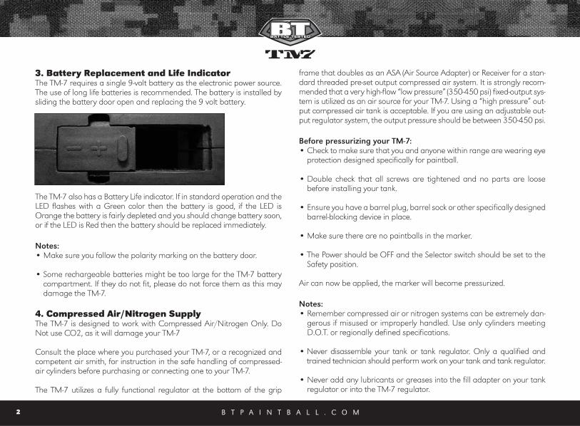
3. Battery Replacement and Life IndicatorThe TM-7 requires a single 9-volt battery as the electronic power source.The use of long life batteries is recommended. The battery is installed bysliding the battery door open and replacing the 9 volt battery.
The TM-7 also has a Battery Life indicator. If in standard operation and theLED flashes with a Green color then the battery is good, if the LED isOrange the battery is fairly depleted and you should change battery soon,or if the LED is Red then the battery should be replaced immediately.
Notes: • Make sure you follow the polarity marking on the battery door.
• Some rechargeable batteries might be too large for the TM-7 batterycompartment. If they do not fit, please do not force them as this maydamage the TM-7.
4. Compressed Air/Nitrogen Supply The TM-7 is designed to work with Compressed Air/Nitrogen Only. DoNot use CO2, as it will damage your TM-7
Consult the place where you purchased your TM-7, or a recognized andcompetent air smith, for instruction in the safe handling of compressed-air cylinders before purchasing or connecting one to your TM-7.
The TM-7 utilizes a fully functional regulator at the bottom of the grip
frame that doubles as an ASA (Air Source Adapter) or Receiver for a stan-dard threaded pre-set output compressed air system. It is strongly recom-mended that a very high-flow “low pressure” (350-450 psi) fixed-output sys-tem is utilized as an air source for your TM-7. Using a “high pressure” out-put compressed air tank is acceptable. If you are using an adjustable out-put regulator system, the output pressure should be between 350-450 psi.
Before pressurizing your TM-7:• Check to make sure that you and anyone within range are wearing eye
protection designed specifically for paintball.
• Double check that all screws are tightened and no parts are loosebefore installing your tank.
• Ensure you have a barrel plug, barrel sock or other specifically designedbarrel-blocking device in place.
• Make sure there are no paintballs in the marker.
• The Power should be OFF and the Selector switch should be set to theSafety position.
Air can now be applied, the marker will become pressurized.
Notes: • Remember compressed air or nitrogen systems can be extremely dan-
gerous if misused or improperly handled. Use only cylinders meetingD.O.T. or regionally defined specifications.
• Never disassemble your tank or tank regulator. Only a qualified andtrained technician should perform work on your tank and tank regulator.
• Never add any lubricants or greases into the fill adapter on your tankregulator or into the TM-7 regulator.
B T P A I N T B A L L . C O M 3
5. Basic Operation Safety and safe marker handling are the most important aspects of paint-ball sports. Please practice each of the following steps with an unloadedmarker before attempting to charge your marker with compressed airand paintballs.
• Do not install compressed air or load paintballs into your TM-7 until youfeel completely confident with your ability to handle your TM-7 safely.
• Keep your finger out of the trigger guard and away from the trigger;point the muzzle of the marker in a safe direction at all times. Keep themarker turned OFF until ready to operate. The TM-7 uses an ON/OFFswitch and a selector switch for its safety devices.
• Always keep your TM-7 pointed in a safe direction. Always use a barrelplug or barrel blocking device. Always use ASTM approved paintballspecific eye protection in any areas where paintball markers may be dis-charged. Remember that the ultimate safety device is you, the operator.
Barrel InstallationMake sure marker is degassed, hopper removed, no paintballs in the feedelbow or breech and the TM-7 is turned off.
• While pointing marker in a safe direction, place the threaded end of thebarrel into the front opening of the marker body.
• Turn the barrel clockwise until it stops (do not over tighten).
• Install a barrel blocking device. This can be a barrel plug or other suchdevice that prevents the accidental discharge of a paintball.
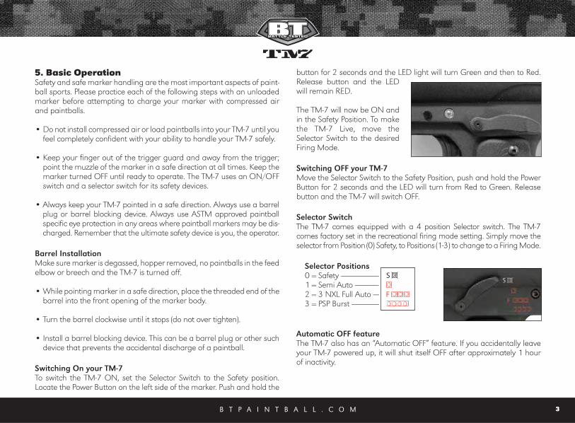
Switching On your TM-7To switch the TM-7 ON, set the Selector Switch to the Safety position.Locate the Power Button on the left side of the marker. Push and hold the
button for 2 seconds and the LED light will turn Green and then to Red.Release button and the LEDwill remain RED.
The TM-7 will now be ON andin the Safety Position. To makethe TM-7 Live, move theSelector Switch to the desiredFiring Mode.
Switching OFF your TM-7Move the Selector Switch to the Safety Position, push and hold the PowerButton for 2 seconds and the LED will turn from Red to Green. Releasebutton and the TM-7 will switch OFF.
Selector SwitchThe TM-7 comes equipped with a 4 position Selector switch. The TM-7comes factory set in the recreational firing mode setting. Simply move theselector from Position (0) Safety, to Positions (1-3) to change to a Firing Mode.
Selector Positions0 = Safety ------------------------1 = Semi Auto ---------------2 = 3 NXL Full Auto -----3 = PSP Burst ------------------
Automatic OFF featureThe TM-7 also has an “Automatic OFF” feature. If you accidentally leaveyour TM-7 powered up, it will shut itself OFF after approximately 1 hourof inactivity.
B T P A I N T B A L L . C O M4
Eye Function The TM-7 board is pre-programmed to activate the eye system each timethe marker is powered up. See Section 7 (Break beam Eyes Operation) formore details.
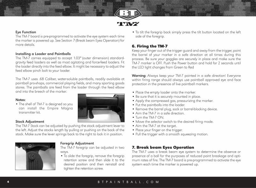
Installing a Loader and PaintballsThe TM-7 comes equipped to accept 1.03" (outer dimension) standard-gravity feed loaders as well as most agitating and force-feed loaders. Fitthe loader directly into the feed elbow. It might be necessary to adjust thefeed elbow pinch bolt to your loader.
The TM-7 uses .68 Caliber, water-soluble paintballs, readily available atpaintball pro-shops, commercial playing fields, and many sporting goodsstores. The paintballs are feed from the loader through the feed elbowand into the breech of the marker.
Notes: • The shell of TM-7 is designed so you
can install the Empire Magna transmitter kit.
Stock AdjustmentThe TM-7 Stock can be adjusted by pushing the stock adjustment lever tothe left. Adjust the stocks length by pulling or pushing on the back of thestock. Make sure the lever springs back to the right to lock it in position.
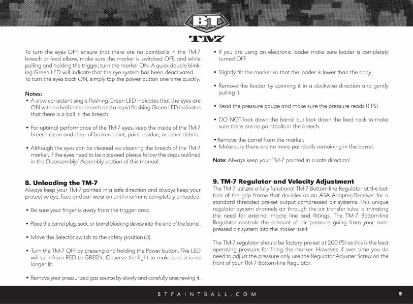
Foregrip AdjustmentThe TM-7 foregrip can be adjusted in twoways. • To slide the foregrip, remove the foregrip
retention screw and then slide it to thedesired position and then reinstall andtighten the retention screw.
• To tilt the foregrip back simply press the tilt button located on the leftside of the foregrip.
6. Firing the TM-7Keep your finger out of the trigger guard and away from the trigger, pointthe barrel of your marker in a safe direction at all times during thisprocess. Be sure your goggles are securely in place and make sure theTM-7 marker is OFF. Push the Power button and hold for 2 seconds untilthe LED light changes from Green to Red
Warning: Always keep your TM-7 pointed in a safe direction! Everyonewithin firing range should always use paintball approved eye and faceprotection in the presence of live paintball markers.
• Place the empty loader onto the marker. • Be sure that it is securely mounted in place. • Apply the compressed gas, pressurizing the marker. • Put the paintballs into the loader. • Remove the barrel plug, sock or barrel-blocking device. • Aim the TM-7 in a safe direction. • Turn the TM-7 ON.• Move the selector switch to the desired firing mode. • Aim the TM-7 at the target. • Place your finger on the trigger. • Pull the trigger with a smooth squeezing motion.
7. Break beam Eyes OperationThe TM-7 uses a break beam eye system to determine the absence orpresence of a ball for the purposes of reduced paint breakage and opti-mum rates of fire. The TM-7 board is pre-programmed to activate the eyesystem each time the marker is powered up.
B T P A I N T B A L L . C O M 5
To turn the eyes OFF, ensure that there are no paintballs in the TM-7breech or feed elbow, make sure the marker is switched OFF, and whilepulling and holding the trigger, turn the marker ON. A quick double blink-ing Green LED will indicate that the eye system has been deactivated. To turn the eyes back ON, simply tap the power button one time quickly.
Notes:• A slow consistent single flashing Green LED indicates that the eyes are
ON with no ball in the breech and a rapid flashing Green LED indicatesthat there is a ball in the breech.
• For optimal performance of the TM-7 eyes, keep the inside of the TM-7breech clean and clear of broken paint, paint residue, or other debris.
• Although the eyes can be cleaned via cleaning the breech of the TM-7marker, if the eyes need to be accessed please follow the steps outlinedin the Disassembly/ Assembly section of this manual.
8. Unloading the TM-7Always keep your TM-7 pointed in a safe direction and always keep yourprotective eye, face and ear wear on until marker is completely unloaded.
• Be sure your finger is away from the trigger area.
• Place the barrel plug, sock, or barrel blocking device into the end of the barrel.
• Move the Selector switch to the safety position (0).
• Turn the TM-7 OFF by pressing and holding the Power button. The LEDwill turn from RED to GREEN. Observe the light to make sure it is nolonger lit.
• Remove your pressurized gas source by slowly and carefully unscrewing it.
• If you are using an electronic loader make sure loader is completelyturned OFF.
• Slightly tilt the marker so that the loader is lower than the body.
• Remove the loader by spinning it in a clockwise direction and gentlypulling it.
• Read the pressure gauge and make sure the pressure reads 0 PSI.
• DO NOT look down the barrel but look down the feed neck to makesure there are no paintballs in the breech.
•Remove the barrel from the marker.• Make sure there are no more paintballs remaining in the barrel.
Note: Always keep your TM-7 pointed in a safe direction!
9. TM-7 Regulator and Velocity AdjustmentThe TM-7 utilizes a fully functional TM-7 Bottom-line Regulator at the bot-tom of the grip frame that doubles as an ASA Adapter/Receiver for astandard threaded pre-set output compressed air systems. This uniqueregulator system channels air through the air transfer tube, eliminatingthe need for external macro line and fittings. The TM-7 Bottom-lineRegulator controls the amount of air pressure going from your com-pressed air system into the maker itself.
The TM-7 regulator should be factory pre-set at 200 PSI as this is the bestoperating pressure for firing the marker. However, if over time you doneed to adjust the pressure only use the Regulator Adjuster Screw on thefront of your TM-7 Bottom-line Regulator.
B T P A I N T B A L L . C O M6
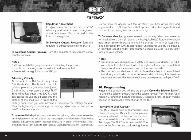
Regulator AdjustmentIf adjustments are needed use a 3/16"Allen key and insert it into the regulatoradjustment screw. This is located in thefront of the regulator.
To Increase Output Pressure- Turn the regulator’s adjustment screw clockwise.
To Decrease Output Pressure- Turn the regulator’s adjustment screwcounter-clockwise.
Notes: • Always watch the gauge as you are adjusting the pressure. • The Bottom-line regulator should not be disassembled.• Never set the regulator above 200 psi.
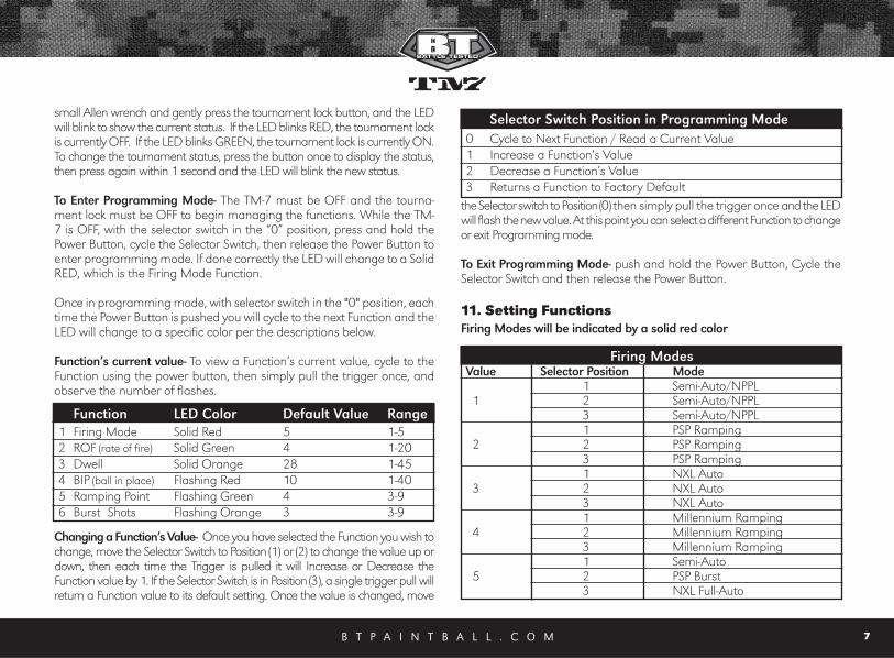
Adjusting VelocityAt the back of the TM-7 main body is theBolt Guide Cap. The holes in the boltguide cap serve as your velocity adjuster.Confirm that the pressure on your TM-7Bottom-line Regulator is at 200 PSI. Youcan access the velocity adjuster thru thebottom of the shell, just in front of thebattery door .Then you can increase or decrease the velocity on your TM-7 by tightening or loosening the velocity adjustment screw, with a7/64" inch Allen wrench.
To Increase Velocity- Unscrew or loosen the velocity adjustment screw byturning it toward the left side of the marker (counter clockwise). Rotate thevelocity adjustment screw counter-clockwise in small increments, stop-ping between slight turns to test velocity, until desired velocity is achieved.
Do not back the adjuster out too far. Stop if you hear an air leak, andadjust back in a 1/4 turn. A paintball specific radar chronograph shouldbe used to accurately measure your velocity.
To Decrease Velocity- tighten or screw-in the velocity adjustment screw byturning it toward the right side of the body (clockwise). Rotate the velocityadjustment screw clockwise in small increments (1/4 turn or less), stop-ping between slight turns to test velocity, until desired velocity is achieved.A paintball specific radar chronograph should be used to accuratelymeasure your velocity.
Notes:• This marker was designed with safety and safety standards in mind. If
you attempt to shoot paintballs at a higher velocity than establishedsafety standards, the marker may not function properly.
• This marker is not designed to shoot above the safety limits establishedby industry standards but under certain conditions it may. It is thereforeimportant to check the velocity each time before playing with your TM-7.
10. Programming Note: In this section, you will see the phrase "Cycle the Selector Switch".To Cycle the Selector Switch, move the Selector Switch from Position (0) toPosition (3) and then back to Position (0), stopping briefly at each middleposition to observe the color change of the LED.
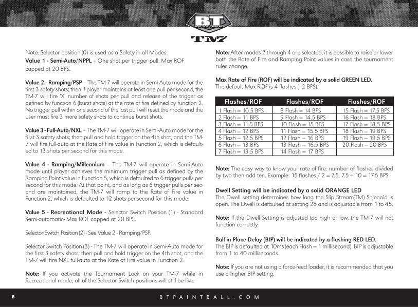
Tournament Lock On/OFFThe TM-7 comes with a Tournament Lockwhich will lock your TM-7 into the firing modecurrently selected. The Tournament lock but-ton is accessed thru a small hole at the top ofthe trigger. The TM-7 must be turned OFF tochange the Tournament Lock setting. Use a
small Allen wrench and gently press the tournament lock button, and the LEDwill blink to show the current status. If the LED blinks RED, the tournament lockis currently OFF. If the LED blinks GREEN, the tournament lock is currently ON.To change the tournament status, press the button once to display the status,then press again within 1 second and the LED will blink the new status.
To Enter Programming Mode- The TM-7 must be OFF and the tourna-ment lock must be OFF to begin managing the functions. While the TM-7 is OFF, with the selector switch in the “0” position, press and hold thePower Button, cycle the Selector Switch, then release the Power Button toenter programming mode. If done correctly the LED will change to a SolidRED, which is the Firing Mode Function.
Once in programming mode, with selector switch in the "0" position, eachtime the Power Button is pushed you will cycle to the next Function and theLED will change to a specific color per the descriptions below.
Function’s current value- To view a Function’s current value, cycle to theFunction using the power button, then simply pull the trigger once, andobserve the number of flashes.
Changing a Function’s Value- Once you have selected the Function you wish tochange, move the Selector Switch to Position (1) or (2) to change the value up ordown, then each time the Trigger is pulled it will Increase or Decrease theFunction value by 1. If the Selector Switch is in Position (3), a single trigger pull willreturn a Function value to its default setting. Once the value is changed, move
the Selector switch to Position (0) then simply pull the trigger once and the LEDwill flash the new value. At this point you can select a different Function to changeor exit Programming mode.
To Exit Programming Mode- push and hold the Power Button, Cycle theSelector Switch and then release the Power Button.
11. Setting FunctionsFiring Modes will be indicated by a solid red color
B T P A I N T B A L L . C O M 7
Function LED Color Default Value Range1 Firing Mode Solid Red 5 1-52 ROF (rate of fire) Solid Green 4 1-203 Dwell Solid Orange 28 1-454 BIP (ball in place) Flashing Red 10 1-405 Ramping Point Flashing Green 4 3-96 Burst Shots Flashing Orange 3 3-9
Selector Switch Position in Programming Mode 0 Cycle to Next Function / Read a Current Value1 Increase a Function’s Value2 Decrease a Function’s Value3 Returns a Function to Factory Default
Firing ModesValue Selector Position Mode
1 Semi-Auto/NPPL1 2 Semi-Auto/NPPL
3 Semi-Auto/NPPL1 PSP Ramping
2 2 PSP Ramping3 PSP Ramping1 NXL Auto
3 2 NXL Auto3 NXL Auto1 Millennium Ramping
4 2 Millennium Ramping3 Millennium Ramping1 Semi-Auto
5 2 PSP Burst3 NXL Full-Auto
B T P A I N T B A L L . C O M8
Note: Selector position (0) is used as a Safety in all Modes.Value 1 - Semi-Auto/NPPL – One shot per trigger pull. Max ROFcapped at 20 BPS.
Value 2 - Ramping/PSP – The TM-7 will operate in Semi-Auto mode for thefirst 3 safety shots; then if player maintains at least one pull per second, theTM-7 will fire ‘X’ number of shots per pull and release of the trigger asdefined by function 6 (burst shots) at the rate of fire defined by function 2.No trigger pull within one second of the last pull will reset the mode and theuser must fire 3 more safety shots to continue burst shots.
Value 3 - Full-Auto/NXL – The TM-7 will operate in Semi-Auto mode for thefirst 3 safety shots; then pull and hold trigger on the 4th shot, and the TM-7 will fire full-auto at the Rate of Fire value in Function 2, which is default-ed to 13 shots per second for this mode.
Value 4 - Ramping/Millennium – The TM-7 will operate in Semi-Automode until player achieves the minimum trigger pull as defined by theRamping Point value in Function 5, which is defaulted to 6 trigger pulls persecond for this mode. At that point, and as long as 6 trigger pulls per sec-ond are maintained, the TM-7 will ramp to the Rate of Fire value inFunction 2, which is defaulted to 12 shots-per-second for this mode.
Value 5 - Recreational Mode - Selector Switch Position (1) - StandardSemi-automatic- Max ROF capped at 20 BPS.
Selector Switch Position (2) - See Value 2 - Ramping/PSP.
Selector Switch Position (3) - The TM-7 will operate in Semi-Auto mode forthe first 3 safety shots; then pull and hold trigger on the 4th shot, and theTM-7 will fire NXL full-auto at the Rate of Fire value in Function 2.
Note: If you activate the Tournament Lock on your TM-7 while inRecreational mode, all of the Selector Switch positions will still be live.
Note: After modes 2 through 4 are selected, it is possible to raise or lowerboth the Rate of Fire and Ramping Point values in case the tournamentrules change.
Max Rate of Fire (ROF) will be indicated by a solid GREEN LED.The default Max ROF is 4 flashes (12 BPS).
Note: The easy way to know your rate of fire: number of flashes dividedby two then add ten. Example: 15 flashes / 2 = 7.5, 7.5 + 10 = 17.5 BPS
Dwell Setting will be indicated by a solid ORANGE LEDThe Dwell setting determines how long the Slip Stream(TM) Solenoid isopen. The Dwell is defaulted at setting 28 and is adjustable from 1 to 45.
Note: If the Dwell Setting is adjusted too high or low, the TM-7 will notfunction correctly.
Ball in Place Delay (BIP) will be indicated by a flashing RED LED.The BIP is defaulted at 10ms (each Flash = 1 millisecond). BIP is adjustablefrom 1 to 40 milliseconds.
Note: If you are not using a force-feed loader, it is recommended that youuse a higher BIP setting.
Flashes/ROF Flashes/ROF Flashes/ROF1 Flash = 10.5 BPS 2 Flash = 11 BPS3 Flash = 11.5 BPS4 Flash = 12 BPS5 Flash = 12.5 BPS6 Flash = 13 BPS7 Flash = 13.5 BPS
8 Flash = 14 BPS9 Flash = 14.5 BPS10 Flash = 15 BPS11 Flash = 15.5 BPS12 Flash = 16 BPS13 Flash = 16.5 BPS14 Flash = 17 BPS
15 Flash = 17.5 BPS16 Flash = 18 BPS17 Flash = 18.5 BPS18 Flash = 19 BPS19 Flash = 19.5 BPS20 Flash = 20 BPS
B T P A I N T B A L L . C O M 9
Ramping Point will be indicated by a flashing GREEN LED.
The default ramping point is 4 (4.5 BPS). Ramping Point is adjustable from(4 to 9.5 BPS). Please see chart for corresponding flashes and BPS settings. Burst Shots will be indicated by a flashing ORANGE LED.
The Burst shot value is defaulted to 3 and is adjustable from (3-9).
Programming Example: If you are in the Default Recreational Firing modeand want to go to Semi-Auto/NPPL. Push and hold the Power Button, cyclethe Selector Switch, then release the Power Button and the LED will be RED.Move the Selector Switch to position (2) and pull the trigger 4 times and thenmove the Selector switch back to position (0) and pull the trigger once. TheLED will now flash 1 time, to show that the Firing mode has been changedto Semi-Auto/NPPL.
Factory Board ResetTo reset all the Functions to the defaults, turn OFF your TM-7, then pressand hold the Tournament Lock button in for 5 seconds. The LED will blinkAMBER to confirm the reset.
12. Trigger AdjustmentsThe TM-7 features a Hall Effect Sensor Trigger. There is no trigger switch
to worry about, clog with paint, or break. The TM-7 trigger can be adjust-ed by the four set screws in the trigger.
When a trigger pull is recognized, the LED will quickly flash a dim Red foreach trigger pull. If no trigger pull is recognized, the LED flashes normal-ly based on the status of the eyes and battery power level.
Before making any trigger adjustments, De-Gas the TM-7, make sure thegauge reads 0 psi, then switch On the TM-7 with eyes turned OFF to easilymonitor the current activation point.
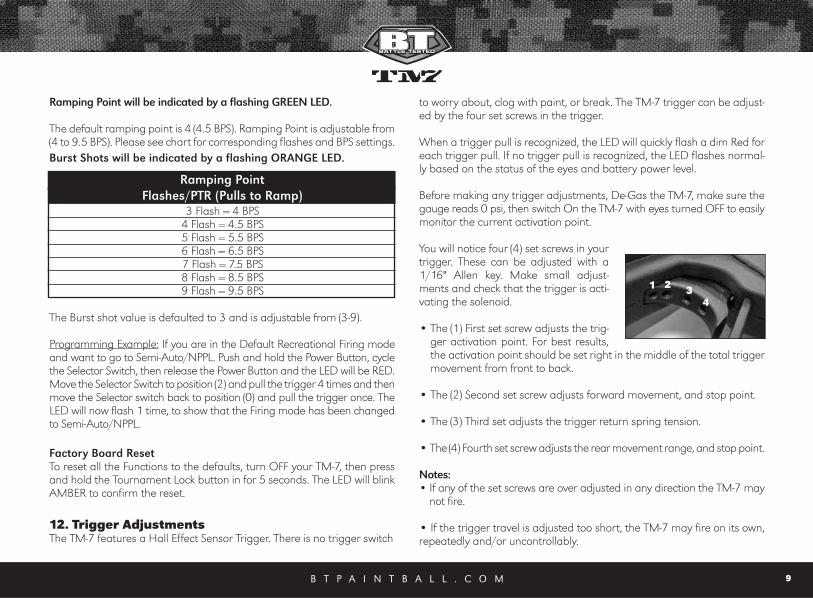
You will notice four (4) set screws in yourtrigger. These can be adjusted with a1/16" Allen key. Make small adjust-ments and check that the trigger is acti-vating the solenoid.
• The (1) First set screw adjusts the trig-ger activation point. For best results,the activation point should be set right in the middle of the total triggermovement from front to back.
• The (2) Second set screw adjusts forward movement, and stop point.
• The (3) Third set adjusts the trigger return spring tension.
• The (4) Fourth set screw adjusts the rear movement range, and stop point.
Notes:• If any of the set screws are over adjusted in any direction the TM-7 may
not fire.
• If the trigger travel is adjusted too short, the TM-7 may fire on its own,repeatedly and/or uncontrollably.
3 Flash = 4 BPS4 Flash = 4.5 BPS5 Flash = 5.5 BPS6 Flash = 6.5 BPS7 Flash = 7.5 BPS8 Flash = 8.5 BPS9 Flash = 9.5 BPS
Ramping PointFlashes/PTR (Pulls to Ramp)
1 2 34
B T P A I N T B A L L . C O M10
13. General MaintenanceCAUTION: Before attempting to perform any maintenance operations,make sure that all paintballs and propellant sources have been removedfrom the marker and that the regulator gauge reads 0 psi. Install a bar-rel blocking device, move the Selector switch to the OFF position and pushPower button and hold for over 2 seconds until the LED light changesfrom Red to Green, and keep the TM-7 power OFF.
Keep your TM-7 clean and lubricated to eliminate the friction that wouldprevent reliable operation. Clean and lube the marker before each use,and do not put it away dirty. Do not use oils made for paintball markers,real firearms or pneumatic tools, do not use oils at all. Do Not use petro-leum-based lubricants in the lubrication of this marker. Teflon or silicon(NON-spray only) lubricants designed for use on o-rings may be used forlubrication for the bolt, bolt guide and poppet area only. Only use greasesupplied with your TM-7.
The outer plastic shell can be rinsed with warm water once all the internalshave been removed. Make sure it is fully dry before reassembling the TM-7.
Notes: • Do not rinse the Tm-7 Shell under water without fully disassembling the
marker, as you will damage the electronics.
• Do Not work on your TM-7 until the Air source is removed and it is verifiedthat the regulator gauge reads 0 psi and no air is trapped in the TM-7.
14. TM-7 Assembly/DisassemblyCAUTION: Before attempting to perform any marker disassembly, makesure that all paintballs and propellant sources have been removed fromthe marker and that the regulator gauge reads 0 psi. Install a barrelblocking device, move the Selector switch to the Safety position and pushPower button and hold for 2 seconds until the LED light changes from Redto Green, and keep the TM-7 power OFF.
Disassembly Tips• Make sure you have a clean area to work on your marker.
• Do not remove the Air Transfer tube from the body and regulator; theseparts are assembled tightly at the factory to prevent leaks.
• When separating the Shell for the first time, locate the Selector shaftand Trigger, notice their position for easy reassembly.
• Make sure the Main spring is installed correctly on the Bolt, as it needsto be installed in the right direction.
• Install the Stock lock and Stock at the same time. Install the Stock lockinto the Stock arms and place them in the shell at the same time.
• After reassembling the TM-7 recheck your trigger activation settings.
Visit PaintballSolutions.com for additional information.
Barrel It is recommended that the barrel be removed before and other mainte-nance or disassembly is performed. Simply turn the barrel counter-clockwise to remove. Use warm water and a barrel cleaning device to keep theBarrel in top condition.
Rear Sight The rear sight rail can be removed by loosening the screw with a 1/8”Allen wrench and then lift the rear sight off.
Feed Elbow To remove the feed elbow, push the release button on the left side of thefeed elbow and slide it forward about 1 inch and lift it off. The Feed elbowdoes not slide off the front of the rail.
B T P A I N T B A L L . C O M 11
Note: Make sure when the feed elbow is reinstalled, it lines up with thehole on the right side of the shell.
Foregrip Using a 7/64" Allen wrench, remove the socket head screw and slide theforegrip forward and off of the body.
Selector ArmIt is not necessary to remove the selector arm when dissembling the TM-7. Using a 1/16" Allen wrench, remove the flat head screw which holdsthe selector arm to the selector shaft.
Note: The Selector Arm is keyed into the selector shaft. Make sure theyare aligned before reinstalling the selector arm screw.
GripsUsing a 5/64" Allen wrench, remove the four 6-32 button head screws holdingthe grips in place. Notice that the lower screws are longer than the top grip screws.
Separating ShellOnce the parts above have been removed the shell can now be separat-ed. The shell is separated by loosening the shell screws.
• Using a 7/64" Allen key loosen the 7 socket head screws, located onthe left side shell.
• Also remove the 2 flat head screws, located above the regulator with a5/64" Allen wrench.
• The left side shell can now be separated from the right, by lifting it off.
Notes: • It is not necessary to remove the picatinny side rails to separate the shells.
• Once the left shell has been removed, there are several componentswhich will be loose. These include the battery door, trigger, trigger guard, trig-ger spring, and stock assembly. Make sure you do not lose any of these parts.
Trigger The trigger can be removed by simply lifting it out of the right side shell.When reinstalling it, make sure the trigger spring is seated correctly. Seethe picture below for correct installation.
Trigger spring The trigger spring serves as a dual purpose spring. It holds the selectorswitch in position and gives the trigger a spring return. See the picturebelow for correct installation.
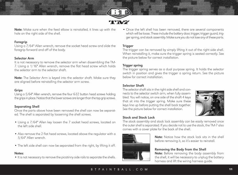
Selector Shaft The selector shaft sits in the right side shell and con-nects to the selector switch arm, when fully assem-bled. You will notice, on one side of the shaft 4 keysthat sit into the trigger spring. Make sure thesekeys line up before putting the shell back together.See the picture below for correct installation.
Stock and Stock Lock The stock assembly and stock lock assembly can be easily removed oncethe outer shell is separated. If you decide not to use the stock, the TM-7 alsocomes with a cover plate for the back of the shell.
Note: Notice how the stock lock sits in the shellbefore removing it, so it’s easier to reinstall.
Removing the Body from the ShellNote: Before removing the body assembly fromthe shell, it will be necessary to unplug the batteryharness and lift the wiring harness guide.
B T P A I N T B A L L . C O M12
• Separate the shells as described, remove the stock lock and stockassemblies.
• Disconnect the the battery harness and lift the wiring harness guide.
• Lift the body assembly from the right side shell
Removal, Installation and Cleaning of Ball Detents• Using a 5/64" Allen key, insert Allen key into detent cover and turn
counter-clockwise.
• Clean the detents with a damp cloth and apply a small amount of sup-plied grease to the outer sides of the detents if sticking is an issue.
• Installation is the reverse of the removal. Do not over tighten the BallDetent covers!
Note: Be careful not to lose any of the detent parts as they are small.
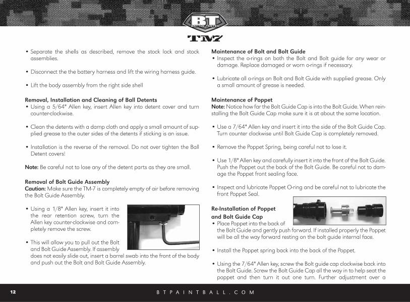
Removal of Bolt Guide Assembly Caution: Make sure the TM-7 is completely empty of air before removingthe Bolt Guide Assembly.
• Using a 1/8" Allen key, insert it intothe rear retention screw, turn theAllen key counter-clockwise and com-pletely remove the screw.
• This will allow you to pull out the Boltand Bolt Guide Assembly. If assemblydoes not easily slide out, insert a barrel swab into the front of the bodyand push out the Bolt and Bolt Guide Assembly.
Maintenance of Bolt and Bolt Guide• Inspect the o-rings on both the Bolt and Bolt guide for any wear or
damage. Replace damaged or worn o-rings if necessary.
• Lubricate all o-rings on Bolt and Bolt Guide with supplied grease. Onlya small amount of grease is needed.
Maintenance of PoppetNote: Notice how far the Bolt Guide Cap is into the Bolt Guide. When rein-stalling the Bolt Guide Cap make sure it is at about the same location.
• Use a 7/64" Allen key and insert it into the side of the Bolt Guide Cap.Turn counter clockwise until Bolt Guide Cap is completely removed.
• Remove the Poppet Spring, being careful not to lose it.
• Use 1/8" Allen key and carefully insert it into the front of the Bolt Guide.Push the Poppet out the back of the Bolt Guide. Be careful not to dam-age the Poppet front sealing face.
• Inspect and lubricate Poppet O-ring and be careful not to lubricate thefront Poppet Seal.
Re-Installation of Poppetand Bolt Guide Cap• Place Poppet into the back of
the Bolt Guide and gently push forward. If installed properly the Poppetwill be all the way forward resting on the bolt guide internal face.
• Install the Poppet spring back into the back of the Poppet.
• Using the 7/64" Allen key, screw the Bolt guide cap clockwise back intothe Bolt Guide. Screw the Bolt Guide Cap all the way in to help seat thepoppet and then turn it out one turn. Further adjustment over a

B T P A I N T B A L L . C O M 13
chronograph will be needed to achieve desired velocity.
Re-Installation of Main Spring, Bolt and Bolt Guide Assembly• Slide the Main Spring onto Bolt, and then the Bolt onto Bolt Guide, so it
is one assembly. You will notice, one end of the spring is smaller and willlock onto the bolt.
• Insert Bolt Assemblyback into the body.
• Line up the alignmenthole on the guide with the alignment pin on the body and slide the boltassembly fully forward to the body.
• Holding the bolt assembly tight into the back of the body with one hand,reinstall the Bolt Guide retention screw and tighten using the 1/8" Allen key.
Circuit Board Removal The Circuit Board should only need to be removed to clean the break beam eyes.
• Remove the Body Assembly from the shell.
• Using a 5/64" Allen key, remove the two Circuit Board screws and gently remove the Circuit Board.
Wiring Harness RemovalNote: The wiring harness should only need tobe removed if you are washing the right shellof the TM-7. • Carefully pull the 2 battery spring tabs out of
the right side shell, using needle nose pliers.Be careful not to break the wires from the bat-tery tabs.
• Then lift the wiring harness guide OFF,and remove harness.
Re-Installation of Wiring HarnessMake sure the wire harness is routedthrough the circuit board and along thebody above the circuit board as shownand not through the trigger area. Failureto route the wires properly will result indestruction of the wires during re-installation of the shell, and can resultin an electrical fire when the battery is installed. Destruction of the wireharness is not covered under warranty.
Regulator Hex AdjustmentThe Regulator has 2 Hex spacers which hold the shell together and the gripson. If they need adjusting, simply insert an Allen key and push it thru theshell and hex. This will align the hex spacers and the screw will go in easily.
15. Storage and TransportationIMPORTANT: Never carry your TM-7 uncased when not on a playing field.The non-playing public and law enforcement personnel may not be ableto distinguish between a paintball marker and firearm. For your own safety and to protect the image of the sport, always carry your TM-7 in asuitable marker case or in the box in which it was shipped.
• Your TM-7 must be clear of all paint and propellant when not being used.
• Make sure the TM-7 marker is OFF. Push the Power button and hold for2 seconds until the LED light changes from Red to Green.
• Put the barrel blocking device in its place. Make sure the marker is clean.
• Store your TM-7 in a clean, cool, dry place.
B T P A I N T B A L L . C O M14
• Keep your TM-7 away from unauthorized and unsafe users.
• It may be a good idea to remove the battery when storing your TM-7to prevent unauthorized use.This is not a toy. Misuse may cause seri-ous injury or death. Eye Protection designed specifically for paintballmust be worn by the user and persons within range. Recommend 18years of age or older to purchase. Persons under 18 years of age musthave adult supervision.
Your TM-7 must be clear of all paint and any source of propellant duringtransportation to and from the playing field. Keep your barrel blockingdevice in place. Keep the TM-7 Marker switched OFF. Protect your TM-7from excessive heat during transportation. Observe and obey all local, state and federal laws concerning the trans-portation of paintball markers. For information concerning any of thelaws in your area, contact your nearby law enforcement agency.
If you must ship your TM-7 for any reason, the box in which you purchasedthe marker should be used to protect your marker against rough handlingduring transport.
Never ship charged CO2 or pressurized gas cylinders!
16. Trouble Shooting Guide Note: If you are experiencing any problems and you are using anyaftermarket parts, it is necessary to re-install the factory parts andre-test before attempting any troubleshooting, as non-factory after-market parts are not designed by BT Paintball to work in the TM-7,and they may be the cause of the problems. Do not contact BTPaintball until you have returned the TM-7 to factory stock conditionand tested.
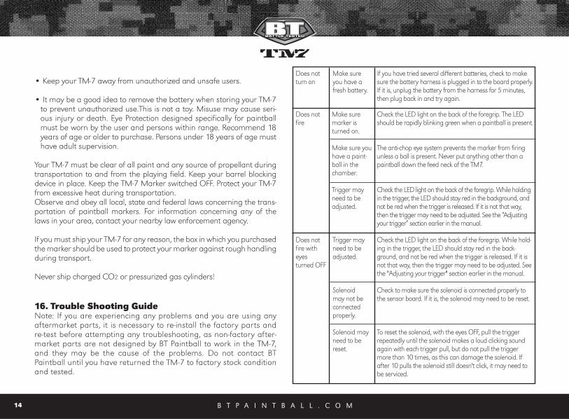
Does notturn on
Make sureyou have afresh battery.
If you have tried several different batteries, check to makesure the battery harness is plugged in to the board properly.If it is, unplug the battery from the harness for 5 minutes,then plug back in and try again.
Does notfire
Make suremarker isturned on.
Make sure youhave a paint-ball in thechamber.
Trigger mayneed to beadjusted.
Check the LED light on the back of the foregrip. The LEDshould be rapidly blinking green when a paintball is present.
The anti-chop eye system prevents the marker from firingunless a ball is present. Never put anything other than apaintball down the feed neck of the TM7.
Check the LED light on the back of the foregrip. While holdingin the trigger, the LED should stay red in the background, andnot be red when the trigger is released. If it is not that way,then the trigger may need to be adjusted. See the “Adjustingyour trigger” section earlier in the manual.
Does notfire witheyesturned OFF
Trigger mayneed to beadjusted.
Solenoid may not be connectedproperly.
Solenoid mayneed to bereset.
Check the LED light on the back of the foregrip. While hold-ing in the trigger, the LED should stay red in the back-ground, and not be red when the trigger is released. If it isnot that way, then the trigger may need to be adjusted. Seethe "Adjusting your trigger" section earlier in the manual.
Check to make sure the solenoid is connected properly tothe sensor board. If it is, the solenoid may need to be reset.
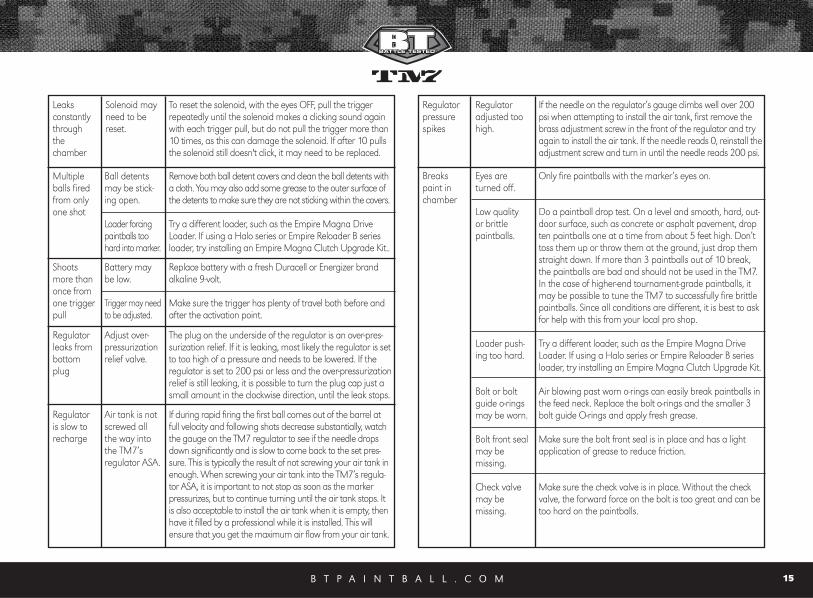
To reset the solenoid, with the eyes OFF, pull the triggerrepeatedly until the solenoid makes a loud clicking soundagain with each trigger pull, but do not pull the triggermore than 10 times, as this can damage the solenoid. Ifafter 10 pulls the solenoid still doesn't click, it may need tobe serviced.
B T P A I N T B A L L . C O M 15
Leaks constantlythroughthe chamber
Solenoid mayneed to bereset.
To reset the solenoid, with the eyes OFF, pull the triggerrepeatedly until the solenoid makes a clicking sound againwith each trigger pull, but do not pull the trigger more than10 times, as this can damage the solenoid. If after 10 pullsthe solenoid still doesn't click, it may need to be replaced.
Multipleballs firedfrom onlyone shot
Shootsmore thanonce fromone triggerpull
Regulatorleaks frombottomplug
Ball detentsmay be stick-ing open.
Loader forcingpaintballs toohard into marker.
Battery maybe low.
Trigger may needto be adjusted.
Adjust over-pressurizationrelief valve.
Remove both ball detent covers and clean the ball detents witha cloth. You may also add some grease to the outer surface ofthe detents to make sure they are not sticking within the covers.
Try a different loader, such as the Empire Magna DriveLoader. If using a Halo series or Empire Reloader B seriesloader, try installing an Empire Magna Clutch Upgrade Kit..
Replace battery with a fresh Duracell or Energizer brandalkaline 9-volt.
Make sure the trigger has plenty of travel both before andafter the activation point.
The plug on the underside of the regulator is an over-pres-surization relief. If it is leaking, most likely the regulator is setto too high of a pressure and needs to be lowered. If theregulator is set to 200 psi or less and the over-pressurizationrelief is still leaking, it is possible to turn the plug cap just asmall amount in the clockwise direction, until the leak stops.
Regulatoris slow torecharge
Air tank is notscrewed allthe way intothe TM7’s regulator ASA.
If during rapid firing the first ball comes out of the barrel atfull velocity and following shots decrease substantially, watchthe gauge on the TM7 regulator to see if the needle dropsdown significantly and is slow to come back to the set pres-sure. This is typically the result of not screwing your air tank inenough. When screwing your air tank into the TM7’s regula-tor ASA, it is important to not stop as soon as the markerpressurizes, but to continue turning until the air tank stops. Itis also acceptable to install the air tank when it is empty, thenhave it filled by a professional while it is installed. This willensure that you get the maximum air flow from your air tank.
Regulatorpressurespikes
Regulatoradjusted toohigh.
If the needle on the regulator’s gauge climbs well over 200psi when attempting to install the air tank, first remove thebrass adjustment screw in the front of the regulator and tryagain to install the air tank. If the needle reads 0, reinstall theadjustment screw and turn in until the needle reads 200 psi.
Breakspaint inchamber
Eyes areturned off.
Low qualityor brittlepaintballs.
Loader push-ing too hard.
Bolt or boltguide o-ringsmay be worn.
Bolt front sealmay be missing.
Check valvemay be missing.
Only fire paintballs with the marker’s eyes on.
Do a paintball drop test. On a level and smooth, hard, out-door surface, such as concrete or asphalt pavement, dropten paintballs one at a time from about 5 feet high. Don’ttoss them up or throw them at the ground, just drop themstraight down. If more than 3 paintballs out of 10 break,the paintballs are bad and should not be used in the TM7.In the case of higher-end tournament-grade paintballs, itmay be possible to tune the TM7 to successfully fire brittlepaintballs. Since all conditions are different, it is best to askfor help with this from your local pro shop.
Try a different loader, such as the Empire Magna DriveLoader. If using a Halo series or Empire Reloader B seriesloader, try installing an Empire Magna Clutch Upgrade Kit.
Air blowing past worn o-rings can easily break paintballs inthe feed neck. Replace the bolt o-rings and the smaller 3bolt guide O-rings and apply fresh grease.
Make sure the bolt front seal is in place and has a lightapplication of grease to reduce friction.
Make sure the check valve is in place. Without the checkvalve, the forward force on the bolt is too great and can betoo hard on the paintballs.
B T P A I N T B A L L . C O M16
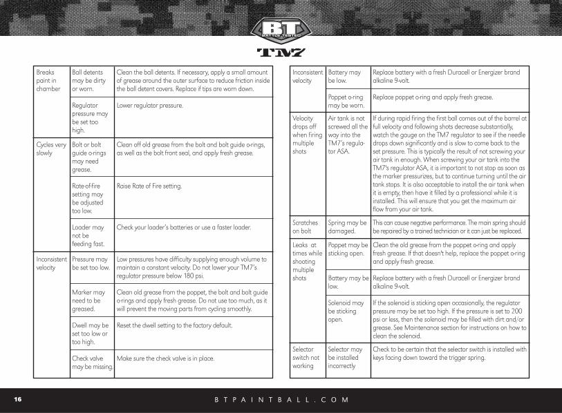
Breakspaint inchamber
Ball detentsmay be dirtyor worn.
Regulatorpressure maybe set toohigh.
Clean the ball detents. If necessary, apply a small amountof grease around the outer surface to reduce friction insidethe ball detent covers. Replace if tips are worn down.
Lower regulator pressure.
Cycles veryslowly
Bolt or boltguide o-ringsmay needgrease.
Rate-of-firesetting maybe adjustedtoo low.
Loader maynot be feeding fast.
Clean off old grease from the bolt and bolt guide o-rings,as well as the bolt front seal, and apply fresh grease.
Raise Rate of Fire setting.
Check your loader’s batteries or use a faster loader.
Inconsistentvelocity
Pressure maybe set too low.
Marker mayneed to begreased.
Dwell may beset too low ortoo high.
Check valvemay be missing.
Low pressures have difficulty supplying enough volume tomaintain a constant velocity. Do not lower your TM7’s regulator pressure below 180 psi.
Clean old grease from the poppet, the bolt and bolt guideo-rings and apply fresh grease. Do not use too much, as itwill prevent the moving parts from cycling smoothly.
Reset the dwell setting to the factory default.
Make sure the check valve is in place.
Inconsistentvelocity
Battery maybe low.
Poppet o-ringmay be worn.
Replace battery with a fresh Duracell or Energizer brandalkaline 9-volt.
Replace poppet o-ring and apply fresh grease.
Velocitydrops offwhen firingmultipleshots
Air tank is notscrewed all theway into theTM7’s regula-tor ASA.
If during rapid firing the first ball comes out of the barrel atfull velocity and following shots decrease substantially,watch the gauge on the TM7 regulator to see if the needledrops down significantly and is slow to come back to theset pressure. This is typically the result of not screwing yourair tank in enough. When screwing your air tank into theTM7's regulator ASA, it is important to not stop as soon asthe marker pressurizes, but to continue turning until the airtank stops. It is also acceptable to install the air tank whenit is empty, then have it filled by a professional while it isinstalled. This will ensure that you get the maximum airflow from your air tank.
Scratcheson bolt
Spring may bedamaged.
This can cause negative performance. The main spring shouldbe repaired by a trained technician or it can just be replaced.
Selectorswitch notworking
Selector maybe installedincorrectly
Check to be certain that the selector switch is installed withkeys facing down toward the trigger spring.
Leaks attimes whileshootingmultipleshots
Poppet may besticking open.
Battery may below.
Solenoid maybe stickingopen.
Clean the old grease from the poppet o-ring and applyfresh grease. If that doesn't help, replace the poppet o-ringand apply fresh grease.
Replace battery with a fresh Duracell or Energizer brandalkaline 9-volt.
If the solenoid is sticking open occasionally, the regulatorpressure may be set too high. If the pressure is set to 200psi or less, then the solenoid may be filled with dirt and/orgrease. See Maintenance section for instructions on how toclean the solenoid.
B T P A I N T B A L L . C O M 17
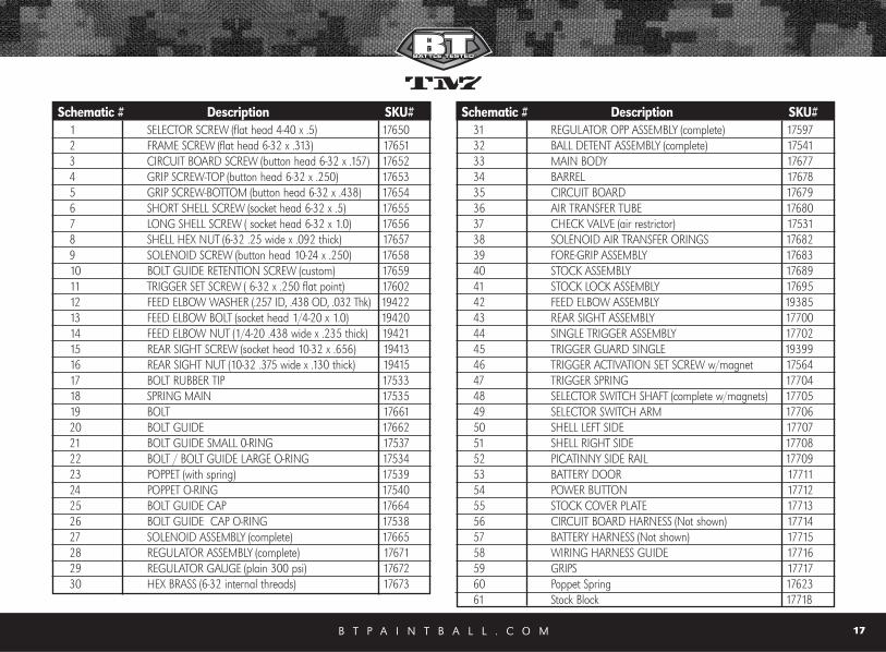
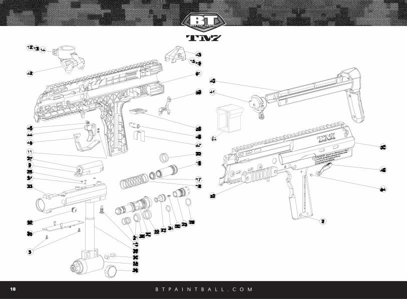
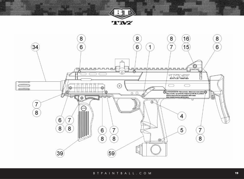
Schematic # Description SKU#1 SELECTOR SCREW (flat head 4-40 x .5) 176502 FRAME SCREW (flat head 6-32 x .313) 176513 CIRCUIT BOARD SCREW (button head 6-32 x .157) 176524 GRIP SCREW-TOP (button head 6-32 x .250) 176535 GRIP SCREW-BOTTOM (button head 6-32 x .438) 176546 SHORT SHELL SCREW (socket head 6-32 x .5) 176557 LONG SHELL SCREW ( socket head 6-32 x 1.0) 176568 SHELL HEX NUT (6-32 .25 wide x .092 thick) 176579 SOLENOID SCREW (button head 10-24 x .250) 1765810 BOLT GUIDE RETENTION SCREW (custom) 1765911 TRIGGER SET SCREW ( 6-32 x .250 flat point) 1760212 FEED ELBOW WASHER (.257 ID, .438 OD, .032 Thk) 1942213 FEED ELBOW BOLT (socket head 1/4-20 x 1.0) 1942014 FEED ELBOW NUT (1/4-20 .438 wide x .235 thick) 1942115 REAR SIGHT SCREW (socket head 10-32 x .656) 1941316 REAR SIGHT NUT (10-32 .375 wide x .130 thick) 1941517 BOLT RUBBER TIP 1753318 SPRING MAIN 1753519 BOLT 1766120 BOLT GUIDE 1766221 BOLT GUIDE SMALL 0-RING 1753722 BOLT / BOLT GUIDE LARGE O-RING 1753423 POPPET (with spring) 1753924 POPPET O-RING 1754025 BOLT GUIDE CAP 1766426 BOLT GUIDE CAP O-RING 1753827 SOLENOID ASSEMBLY (complete) 1766528 REGULATOR ASSEMBLY (complete) 1767129 REGULATOR GAUGE (plain 300 psi) 1767230 HEX BRASS (6-32 internal threads) 17673
Schematic # Description SKU#31 REGULATOR OPP ASSEMBLY (complete) 1759732 BALL DETENT ASSEMBLY (complete) 1754133 MAIN BODY 1767734 BARREL 1767835 CIRCUIT BOARD 1767936 AIR TRANSFER TUBE 1768037 CHECK VALVE (air restrictor) 1753138 SOLENOID AIR TRANSFER ORINGS 1768239 FORE-GRIP ASSEMBLY 1768340 STOCK ASSEMBLY 1768941 STOCK LOCK ASSEMBLY 1769542 FEED ELBOW ASSEMBLY 1938543 REAR SIGHT ASSEMBLY 1770044 SINGLE TRIGGER ASSEMBLY 1770245 TRIGGER GUARD SINGLE 1939946 TRIGGER ACTIVATION SET SCREW w/magnet 1756447 TRIGGER SPRING 1770448 SELECTOR SWITCH SHAFT (complete w/magnets) 1770549 SELECTOR SWITCH ARM 1770650 SHELL LEFT SIDE 1770751 SHELL RIGHT SIDE 1770852 PICATINNY SIDE RAIL 1770953 BATTERY DOOR 1771154 POWER BUTTON 1771255 STOCK COVER PLATE 1771356 CIRCUIT BOARD HARNESS (Not shown) 1771457 BATTERY HARNESS (Not shown) 1771558 WIRING HARNESS GUIDE 1771659 GRIPS 1771760 Poppet Spring 1762361 Stock Block 17718
B T P A I N T B A L L . C O M18
B T P A I N T B A L L . C O M 19
B T P A I N T B A L L . C O M20
18. Warranty Information
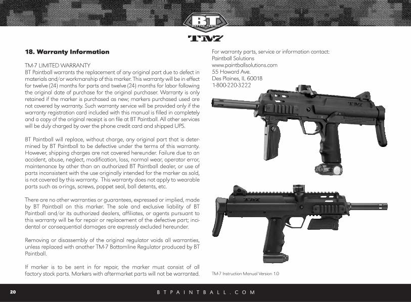
TM-7 LIMITED WARRANTY BT Paintball warrants the replacement of any original part due to defect inmaterials and/or workmanship of this marker. This warranty will be in effectfor twelve (24) months for parts and twelve (24) months for labor followingthe original date of purchase for the original purchaser. Warranty is onlyretained if the marker is purchased as new; markers purchased used arenot covered by warranty. Such warranty service will be provided only if thewarranty registration card included with this manual is filled in completelyand a copy of the original receipt is on file at BT Paintball. All other serviceswill be duly charged by over the phone credit card and shipped UPS.
BT Paintball will replace, without charge, any original part that is deter-mined by BT Paintball to be defective under the terms of this warranty.However, shipping charges are not covered hereunder. Failure due to anaccident, abuse, neglect, modification, loss, normal wear, operator error,maintenance by other than an authorized BT Paintball dealer, or use ofparts inconsistent with the use originally intended for the marker as sold,is not covered by this warranty. This warranty does not apply to wearableparts such as o-rings, screws, poppet seal, ball detents, etc.
There are no other warranties or guarantees, expressed or implied, madeby BT Paintball on this marker. The sole and exclusive liability of BTPaintball and/or its authorized dealers, affiliates, or agents pursuant tothis warranty will be for repair or replacement of the defective part; inci-dental or consequential damages are expressly excluded hereunder.
Removing or disassembly of the original regulator voids all warranties,unless replaced with another TM-7 Bottomline Regulator produced by BTPaintball.
If marker is to be sent in for repair, the marker must consist of all factory stock parts. Markers with aftermarket parts will not be warranted.
For warranty parts, service or information contact: Paintball Solutions www.paintballsolutions.com55 Howard Ave.Des Plaines, IL 60018 1-800-220-3222
TM-7 Instruction Manual Version 1.0
B T P A I N T B A L L . C O M 1
1. Rules for Safe Marker Handling IMPORTANT: Never carry your TM-7 uncased when not on a playing field.The non-playing public and law enforcement personnel may not be ableto distinguish between a paintball marker and firearm. For your own safe-ty and to protect the image of the sport, always carry your TM-7 in a suit-able marker case or in the box in which it was shipped.
• Treat every marker as if it were loaded.• Never look down the barrel of a paintball marker. • Keep your finger OFF the trigger until ready to shoot.• Never point the marker at anything you don’t wish to shoot.• Keep the marker on “safe” until ready to shoot.• Keep the barrel blocking device in/ on the marker’s barrel when not
shooting. • Always remove paintballs and propellant source before disassembly. • After removing air source, point marker in safe direction and discharge
until Marker is degassed.• Store the marker unloaded and degassed in a secure place.• Follow warnings listed on the air source for handling and storage. • Do not shoot at fragile objects such as windows. • Every person within range must wear eye, face and ear protection designed
specifically to stop paintballs and meeting ASTM standard F1776. • Always measure your marker’s velocity before playing paintball and
never shoot at velocities in excess of 91.44 meters (300 feet-per-second).
READ OWNERS MANUAL BEFORE USING.
2. Introduction and SpecificationsCongratulations on your selection of the TM-7 paintball marker. The TM-7is made to provide you with many years of reliable performance. We arehonored that you have chosen the TM-7 as your marker of choice andhope you enjoy using this high quality product.
The patented Valve design, Slip Stream™ Solenoid, Hall Effect Sensor
Trigger, Four Position Selector Switch, set new standards for marker technol-ogy. The TM-7 is precision engineered from Aircraft grade Aluminum andComposite, to meet the demands of the most competitive players, teams,and climates. The ultimate intent of the TM-7 is to exceed your expectations.
We expect you to play hard and play frequently and thus the TM-7 wasbuilt with this in mind. All internal parts, wear, and contact surfaces havebeen heat treated or hard anodized. The toughest and most resilient mate-rials and components have been used in the construction of this marker.
The TM-7 operates on Low-Pressure. The main operating pressure is 180-200 PSI.The pressure can be nominally adjusted and monitored visually via the gauge onthe bottom-line regulator. There is no secondary regulator to worry about.
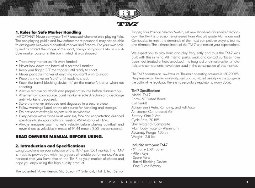
TTMM--77 SSppeecciiffiiccaattiioonnss Model- TM-7Barrel- 9“ Ported BarrelCaliber-68Action- Semi Auto, Ramping, and Full AutoAir source- Compressed Air Battery- One 9 Volt Cycle Rate- 20 BPSShell Material- CompositeMain Body material- AluminumAccuracy Range- 150ft +Weight– 2.5 lbs
IInncclluuddeedd wwiitthh yyoouurr TTMM--77- 9” Barrel (.691 bore)- Allen Keys- Spare Parts - Barrel Blocking Device- One 9 Volt Battery

B T P A I N T B A L L . C O M
Top Related