


Languages
Pages
Legal


Owner’s manual

California Proposition 65 WARNING:Operating, servicing and maintaining a passenger vehicle or off-road vehicle can expose you to chemicals including such as, engine exhaust, carbon monoxide, phthalates and lead, that which are know to the State of California to cause cancer and birth defects or other reproductive harm. To minimize exposure, avoid breathing exhaust, do not idle the engine except as necessary, service your vehicle in a well-ventilated area and wear gloves or wash your hands frequently when servicing your vehicle. For more information go to: www.P65Warnings.ca.gov/passenger-vehicle

Ghibli
Owner's Manual
Dear Customer,
Thank you for choosing a Maserati.
This vehicle represents the result of Maserati's great experience in the design and production of sports, touring andracing vehicles.
With this manual you will acquaint yourself with the equipment and options of your Maserati in order to take advantageof its full potential.
Before driving your vehicle for the first time, we suggest reading the printed Quick Guide carefully in order to quicklyacquaint with commands and functions of your vehicle. You can consult this Owner's Manual and the Maserati TouchControl Plus guide directly from the dashboard touchscreen display of your vehicle.
The updated version of the onboard documentation can be consulted by accessing the section “SERVICES” on the websitewww.maserati.com or by using the specific apps developed for the more common Tablet and Smartphone.
In a dedicated section of this manual you will also find instructions for basic maintenance procedures, in order to ensuresteady levels of performance, quality and safe driving.
Keep in mind that proper maintenance is an essential factor to help preserve the value of the vehicle over time andprotect the environment.
For “Scheduled Maintenance” or any other operation, contact your Authorized Maserati Dealer: you can trust ourtrained technical staff, who is constantly updated and provided with the required equipment in order to ensure that allservice operations are performed properly and reliably.
The Quick guide and other documents contained in onboard documentation kit are integral part of the vehicle andshould always be kept on board.
You can purchase a printed copy of the documents visible on dashboard touchscreen display at your dealer of yourAuthorized Maserati Dealer.
2
WARNING!CALIFORNIA proposition 65.Operating, servicing and maintaining a passenger vehicle or off-road vehicle can expose you to chemicals including suchas, engine exhaust, carbon monoxide, phthalates and lead, that which are know to the State of California to causecancer and birth defects or other reproductive harm. To minimize exposure, avoid breathing exhaust, do not idle theengine except as necessary, service your vehicle in a well-ventilated area and wear gloves or wash your handsfrequently when servicing your vehicle. For more information go to: www.P65Warnings.ca.gov/passenger-vehicle
3

4
Introduction
Before Starting
Understanding the Vehicle
Dashboard Instruments and Controls
Driving
In an Emergency
Maintenance and Care
Features and Specifications
Index
1
2
3
4
5
6
7
8
9
5

6
1 – Introduction
Consulting the Manual . . . . . . . . . . . . . . . . . . . . . . . . . . . . . . . . . . . . 8Abbreviations . . . . . . . . . . . . . . . . . . . . . . . . . . . . . . . . . . . . . . . . . . . 8Updating . . . . . . . . . . . . . . . . . . . . . . . . . . . . . . . . . . . . . . . . . . . . . . . 9Service and Warranty . . . . . . . . . . . . . . . . . . . . . . . . . . . . . . . . . . . . . 10Suggestions for Obtaining Service for Your Vehicle . . . . . . . . . . . . . . 10If You Need Assistance . . . . . . . . . . . . . . . . . . . . . . . . . . . . . . . . . . . . 11Warranty Information . . . . . . . . . . . . . . . . . . . . . . . . . . . . . . . . . . . . 12Reporting Safety Defects . . . . . . . . . . . . . . . . . . . . . . . . . . . . . . . . . . 12Parts Service . . . . . . . . . . . . . . . . . . . . . . . . . . . . . . . . . . . . . . . . . . . 13Aftermarket Parts & Accessories Statement . . . . . . . . . . . . . . . . . . . . 13Symbols . . . . . . . . . . . . . . . . . . . . . . . . . . . . . . . . . . . . . . . . . . . . . . . 14Warnings when Driving . . . . . . . . . . . . . . . . . . . . . . . . . . . . . . . . . . . 15Maserati Roadside Assistance Program(available for USA and Canada only) . . . . . . . . . . . . . . . . . . . . . . . . 16
Vehicle Identification Data . . . . . . . . . . . . . . . . . . . . . . . . . . . . . . . . . 18
7
Consulting the ManualFor an easy identification of the topics,this Manual is divided into sectionsand chapters: each chapter can havemore paragraphs.Within the text, important warningsand notes are also easily identifiablethrough icons.
WARNING!California Proposition 65Operating, servicing and maintaininga passenger vehicle or off-road vehiclecan expose you to chemicals includingsuch as, engine exhaust, carbonmonoxide, phthalates and lead, thatwhich are know to the State ofCalifornia to cause cancer and birthdefects or other reproductive harm. Tominimize exposure, avoid breathingexhaust, do not idle the engine exceptas necessary, service your vehicle in awell-ventilated area and wear glovesor wash your hands frequently whenservicing your vehicle. For moreinformation go to:www.P65Warnings.ca.gov/passenger-vehicle
WARNING!Failure to comply with the instructionscould cause HAZARDOUS SITUATIONSinvolving personal and vehicle safety.
ENVIRONMENTAL!This note indicates the correctbehavior when using the vehicle toprotect the environment.
CAUTION!Aimed at preventing any damage tothe vehicle and thus hazards involvingthe safety of persons.
NOTE:
Additional information regarding thesubject and/or the operationdescribed.
• “Left” and “right” in this manual,always refer to the driving direction.
• All indications and images in thisManual refer to a vehicle withleft-hand drive. On right-hand drivevehicles, some controls are ordereddifferently than shown in theillustrations.
AbbreviationsSome descriptions and terms withparticular meanings are found in thismanual in abbreviated form.
A/C Air-Conditioning system.
ABA Advanced Brake Assist.
ABS Anti-Lock Braking System.
ABSA Active Blind Spot Assist.
ACC Adaptive Cruise Control.
ADAS Advanced Driver AssistanceSystems.
ALR Automatic Locking Retractor.
AQS Air Quality Sensor.
ATC Automatic TemperatureControl.
AWD All-Wheel Drive.
BAS Brake Assist System.
BSA Blind Spot Assist.
BTO Brake Throttle Override.
CAN Controller Area Network.
CC Cruise Control.
CRS Child Restraint System.
DRL Daytime Running Lights.
EBD Electronic Brake-forceDistribution.
ECU Electronic Control Unit.
Introduction
1
8
EDR Event Data Recorder.
EPB Electric Parking Brake.
ESC Electronic Stability Control.
ETC Electronic Throttle Control.
FCW Forward Collision Warning.
HAS Highway Assist.
HSA Hill Start Assist.
HBA Hydraulic Brake Assistance.
I.C.E. Increased Control andEfficiency.
LATCH Lower Anchors and Tetherfor Children.
LDW Lane Departure Warning(LaneSense).
LKA Lane Keeping Assist.
MIL Malfunction Indicator Light.
MTC+ Maserati Touch Control Plus.
OBD On Board Diagnostics.
ORC Occupant RestraintController.
PDC Park Distance Control.
RAB Ready Alert Braking.
RCP Rear Cross Path.
RKE Remote Keyless Entry.
SAB Side Air Bag.
SABIC Supplemental Side Air BagInflatable Curtains.
SBR Seat Belt Reminder.
SRS Supplemental RestraintSystem.
TCS Traction Control System.
TFT Thin Film Transistor.
TPMS Tire Pressure MonitoringSystem.
TSA Traffic Sign Assist.
VIN Vehicle IdentificationNumber.
UpdatingConstant improvements are beingperformed to maintain this vehicle'shigh level of quality. Therefore, theremay be differences between thismanual and your vehicle.Maserati reserves the right to carryout design and functional changesand to provide updates orimprovements.This Owner's Manual illustrates anddescribes all versions of the currentvehicle model. Therefore, some of theequipment and accessories in thispublication may not appear on yourvehicle; please only consider theinformation related to your vehicle.All specifications and illustrationscontained in this manual are as of theManual publishing date.
NOTE:
The updated version of the on-boarddocumentation can be consulted byaccessing the section “SERVICES” onthe website www.maserati.com or byusing the specific apps developed forthe more common Tablet andSmartphone.
Introduction
1
9
Service and WarrantyThe information provided in thismanual is limited to instructions andindications that are strictly requiredfor vehicle use and propermaintenance.By following these instructionscarefully, the vehicle will meet theowner's satisfaction and best results.We advise to have all service andinspections completed only by anAuthorized Maserati Dealer, whereyou will find a specially trained staffand the proper equipment to repairyour vehicle.Please visit the www.maserati.com tofind the nearest Authorized MaseratiDealer.All features and accessories installedon the vehicle have been designed byMaserati engineers and havesuccessfully passed rigorous tests,submitted in all conditions of use.Installing aftermarket components oraccessories not approved by Maseratimay interfere with the vehicleelectronics and compromise drivingsafety and possibly voiding thewarranty coverage.Nor do the warranties cover the costsof repairing damage or conditionscaused by any changes to your vehicle
that do not comply with Maserati’sspecifications.An Authorized Maserati Dealer is atyour complete disposal for anyinformation and questions you mayhave.
Suggestions for ObtainingService for Your Vehicle
Prepare for the AppointmentIf warranty work is required, be sure tohave the right papers with you andtake your warranty folder. Not all workbeing performed may be covered bythe warranty: therefore discussadditional charges with the servicemanager. It is advisable to keep amaintenance log of your vehicle’sservice history, as this can oftenprovide a clue to the current problem.
Prepare a ListMake a written list of your vehicle’sproblems or the specific work you wishto be performed. If the vehicle has hadan accident or work done that is notindicated on the maintenance log,please communicate this to the serviceadvisor.
Optimize the RequestsIf there are a number of items needingattention, it is advisable to discuss thiswith your service advisor to agree onthe order of priorities.At many Authorized Dealers/ServiceCenters, it is possible to obtain aloaner vehicle or a rental vehicle at a
Introduction
1
10
minimal daily charge. If you need arental vehicle, it is advisable to makethese arrangements prior to the visit,for example when you call to set theappointment.
If You Need AssistanceThe manufacturer/Maserati and itsAuthorized Dealers/Service Networkset highest priority to the client’ssatisfaction with the products andservices.Warranty service must be performedby an Authorized MaseratiDealer/Service Center.Should there be any issues, pleasekeep in mind that most matters can beresolved with the following process.
• If for some reason you are still notsatisfied, please contact the generalmanager or owner of the ServiceCenter, it is their responsibility toassist you.
• If a Service Center is unable toresolve the issue, you may contactMaserati Customer Center.
Any communication to theMaseratiConsumer Affairs should include thefollowing information:
• Owner’s name and address.• Owner’s telephone number (homeand office).
• Maserati Service Center name.• Vehicle Identification Number (VIN).• Vehicle delivery date and mileage.
Contact:MASERATI North America, Inc.250 Sylvan AvenueEnglewood CliffsNJ 07632Phone:Maserati Customer Care1-877-MY-MASERATI (877-696-2737) or1-201-510-2369
Introduction
1
11
Warranty InformationPlease refer to the Warranty booklet,included in the Owner’sdocumentation kit, for the terms andprovisions of Maserati warrantiesapplicable to this vehicle and market.
Reporting Safety Defects
NHTSA’s Toll-free Auto SafetyHotlineIf you believe that your vehicle has adefect which could cause a crash,injury or death, immediately informthe National Highway Traffic SafetyAdministration (NHTSA) in addition tonotifying Maserati North America, Inc.If NHTSA receives similar complaints, itmay open an investigation, and if itfinds that a safety defect exists in agroup of vehicles, it may order a recalland remedy campaign. However,NHTSA cannot become involved inindividual problems between you, yourdealer, or Maserati North America, Inc.To contact NHTSA, you may call theVehicle Safety Hotline toll-free at1-888-327-4236 (TTY: 1-800-424-9153),go to http://www.safercar.gov; or writeto: Administrator, NHTSA, Washington,D.C. 20590. You can also obtain otherinformation about motor vehiclesafety from http://www.safercar.gov.
Reporting safety defects in CanadaIf you believe your vehicle has a defectthat could cause a crash or could causeinjury or death, you shouldimmediately inform Transport Canada
in addition to notifying Maserati NorthAmerica, Inc.
Transport Canada can be contacted at:1-800-333-0510Teletypewriter (TTY): 613 990-4500Fax: 1-819-994-3372Mailing Address: Transport Canada -Road Safety, 80 rue Noël, Gatineau,(Quebec) J8Z 0A1.
In CanadaIf you believe that your vehicle has asafety defect, contact the CustomerService Department immediately.Canadian customers who wish toreport a safety defect to the Canadiangovernment should contact TransportCanada, Motor Vehicle DefectInvestigations and Recalls at1-800-333-0510 or go tohttp://www.tc.gc.ca/roadsafety/
Introduction
1
12
Parts ServiceGenuine parts keep the reliability,comfort and performance of your newcar unchanged throughout its life.For service and scheduledmaintenance Maserati suggests you toask for genuine parts since they arethe result of constant research anddevelopment, reliability test and newtechnologies, as well as they arespecifically designed for this vehicle.
Aftermarket Parts &Accessories StatementModification of the vehicle orinstallation of any accessory orcomponents attached to the vehiclewhich alters the original engineeringand/or vehicle operatingspecifications, or which result indamage to the other originalcomponents, electrical interference,electrical short(s), radio static, waterleaks and wind noise may result indamage to genuine components,compromise the safety of the vehicleand affect the validity of the new carwarranty on the vehicle.
Non-genuine Maserati PartsNon-genuine Maserati Parts (whileyou may elect to use non-genuineMaserati parts for maintenance orrepair services), Maserati NorthAmerica, Inc. is not obligated to payfor repairs that include non-genuineMaserati parts or for any damageresulting from the use of non-genuineparts.Maserati will not accept any liabilityfor any parts and accessories notapproved by Maserati, includingDealer-installed accessories not
distributed by Maserati NorthAmerica, Inc.
Introduction
1
13
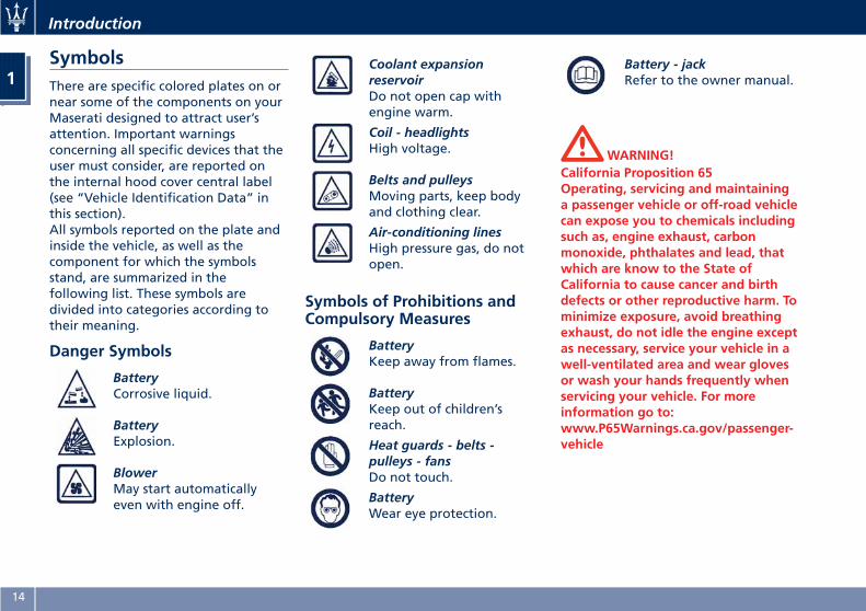
SymbolsThere are specific colored plates on ornear some of the components on yourMaserati designed to attract user’sattention. Important warningsconcerning all specific devices that theuser must consider, are reported onthe internal hood cover central label(see “Vehicle Identification Data” inthis section).All symbols reported on the plate andinside the vehicle, as well as thecomponent for which the symbolsstand, are summarized in thefollowing list. These symbols aredivided into categories according totheir meaning.
Danger Symbols
BatteryCorrosive liquid.
BatteryExplosion.
BlowerMay start automaticallyeven with engine off.
Coolant expansionreservoirDo not open cap withengine warm.
Coil - headlightsHigh voltage.
Belts and pulleysMoving parts, keep bodyand clothing clear.
Air-conditioning linesHigh pressure gas, do notopen.
Symbols of Prohibitions andCompulsory Measures
BatteryKeep away from flames.
BatteryKeep out of children’sreach.
Heat guards - belts -pulleys - fansDo not touch.
BatteryWear eye protection.
Battery - jackRefer to the owner manual.
WARNING!California Proposition 65Operating, servicing and maintaininga passenger vehicle or off-road vehiclecan expose you to chemicals includingsuch as, engine exhaust, carbonmonoxide, phthalates and lead, thatwhich are know to the State ofCalifornia to cause cancer and birthdefects or other reproductive harm. Tominimize exposure, avoid breathingexhaust, do not idle the engine exceptas necessary, service your vehicle in awell-ventilated area and wear glovesor wash your hands frequently whenservicing your vehicle. For moreinformation go to:www.P65Warnings.ca.gov/passenger-vehicle
Introduction
1
14
Warning Symbols
Engine - Engine Oil FillerCapEngine oil. We recommendusing an oil with thecharacteristics indicated inchapter “Refillings” insection “Features andSpecifications”.
Brake fluid reservoirBrake fluid type DOT 4. Donot exceed max. level. Werecommend using a fluidwith the characteristicsindicated in chapter“Refillings” in section“Features andSpecifications”.
Radiator coolant expansionreservoirUse antifreeze liquid forradiators. We recommendusing a liquid with thecharacteristics indicated inchapter “Refillings” insection “Features andSpecifications”.
Windshield washer fluidreservoirWindshield washer. Werecommend using a liquidwith the characteristicsindicated in chapter“Refillings” in section“Features andSpecifications”.
WARNING!California Proposition 65Operating, servicing and maintaininga passenger vehicle or off-road vehiclecan expose you to chemicals includingsuch as, engine exhaust, carbonmonoxide, phthalates and lead, thatwhich are know to the State ofCalifornia to cause cancer and birthdefects or other reproductive harm. Tominimize exposure, avoid breathingexhaust, do not idle the engine exceptas necessary, service your vehicle in awell-ventilated area and wear glovesor wash your hands frequently whenservicing your vehicle. For moreinformation go to:www.P65Warnings.ca.gov/passenger-vehicle
Warnings when DrivingAlways comply with local trafficregulations wherever you drive.Failure to operate this vehicle correctlymay result in loss of control or acollision.Operating this vehicle at excessivespeed or in an altered state or whileintoxicated may result in loss ofcontrol, going off the road, oroverturning. In all these situations acollision with other vehicles or objectsis more likely to happen with the riskto cause an accident that may lead toserious injury.In case of an accident, failure to useseat belts causes the driver andpassengers a greater risk of injury ordeath. Use your seat belt at all times.This Owner's Manual containswarnings against operatingprocedures that could result in acollision or injury or damage to theenvironment. It also contains cautionsagainst procedures that could damagethe vehicle.If you do not read this manual in itsentirety, you may miss importantinformation. Consider carefully allwarnings and cautions.
Introduction
1
15
WARNING!• It is the driver’s responsibility tooperate the vehicle in a safe way: ifyou are distracted while driving youcan lose control and cause seriousaccidents.
•Maserati strongly recommends youuse particular care when operatingthe features and tools that maydistract you.
•Mobile phones, PC, portable audiodevice or other features operatedwhile the vehicle is moving can bevery dangerous and can causeserious accidents, and in some statesis against the law.
• It is very dangerous to send textmessages while driving; do so onlywhen the vehicle is not moving.
• In some Countries/States the use ofmobile phones when driving isforbidden: it is the driver’s soleresponsibility to respect localregulations.
CAUTION!If battery charge is too low, properfunction of some electric/electroniccomponents may not be guaranteed. It
is necessary to recharge the battery inorder to allow all vehicle’s componentsand systems to function correctly.
Maserati RoadsideAssistance Program(available for USA andCanada only)Welcome to Maserati and the benefitsand security of the Maserati RoadsideAssistance Program. Please take amoment to review the benefits listedbelow and available to you throughthe Maserati Roadside AssistanceProgram.
Emergency Roadside ServicesIn the event you require RoadsideAssistance, please call 1-888-371-1802,24 hours a day, 365 days a year. Youwill be connected with a RoadsideAssistance representative who willdispatch a local towing vendor.
Information needed for whenyou callWhen you call, please be prepared toprovide the following information:
• Your Name.• Vehicle Identification Number (VIN).• Location of your vehicle.• Nature of your call (for example; yourequire a tow, vehicle will not start,out of gas, tire service, etc.).
Introduction
1
16
Summary of Program Benefitsand Services• Towing of a disabled registeredMaserati vehicle. In the event aregistered vehicle becomes disabledin connection to a warranty relatedconcern it will be transported to thenearest Authorized MaseratiDealership. You may request thatthe vehicle be taken to a differentAuthorized Maserati Dealer, as longas it is no more than 50 miles furtheraway from the nearest authorizeddealer (one tow per disablement).
• Battery jump start.• Flat tire change providing thevehicle is equipped with a spare tire.
• Fuel delivery (up to 2 gallons).• Lockout Services.• Service Loaner Vehicle: For warrantyrepairs, your dealer may provide youwith a Maserati Service LoanerVehicle (if available) or provide youwith Rental Car allowance: in theevent your vehicle is disabled due toa warranty related concern, we willreimburse you up to $50 per day. Afive (5) day or $250 maximumapplies. In order to receivereimbursement, you must supply thefollowing information within 20
days of the rental car transaction tothe address listed below; the originalpre-printed rental car receipt, whichmust include your name, address,telephone number, VIN, rental datesand the corresponding warrantyrepair order.
Maserati Roadside Assistance ATTN:Maserati Rental Car Claims Dept.P.O. Box 8140 Ft.Washington, PA 19034
NOTE:
An authorized licensed driver must bedriving at the time of the disablement.
Items excluded from coverage:
• Parts, labor, tire repair, rental oftowing equipment, storage fees, orany labor performed at the servicefacility.
• Any form of impound towing, ortowing by someone other than alicensed service station or garage.
• Assistance from a private citizen.
NOTE:
Membership is intended to coveremergencies and is not intended to bea substitute for proper vehiclemaintenance or repair. Repeated callswhich are considered by MaseratiNorth America, Inc. Signature MotorClub, Inc. or Signature Motor Club ofCalifornia, Inc. to be excessive may, atour discretion, result in cancellation ofthe membership.
Emergency road service providers areindependent contractors and are notemployees, agents or representativesof Maserati North America, Inc.Signature Motor Club, Inc. orSignature Motor Club of California,Inc.
Under this Agreement
• You will not be required to pay anysum for services up to the mileagelimit on towing.
• Your registered Maserati vehicle isthe vehicle covered. The VehicleIdentification Number (VIN) thatappears on the vehicle representsyour identification number withSignature Motor Club, Inc. orSignature Motor Club of California,Inc.
Introduction
1
17
• NEW VEHICLES: Your membershipbegins on the date the RegisteredVehicle was originally sold (in servicedate) and continues until theexpiration date of the New CarLimited Warranty or unlessterminated by Maserati NorthAmerica, Inc. for cause.
• PRE OWNED VEHICLES: Yourmembership begins on the date theregistered vehicle was sold (in servicedate) and continues until theexpiration date of the MaseratiCertified Pre-Owned LimitedWarranty or unless terminated byMaserati North America, Inc forcause.
Address Inquiries to
General Inquiries:Maserati Roadside AssistanceP.O. Box 968008Schaumburg, IL 60173
Rental Car Reimbursements:Within 20 days of your rental cartransaction, the original pre-printedrental car receipt, which must includeyour name, address, telephonenumber, VIN, rental dates and thecorresponding warranty repair ordershould be submitted to:
Maserati Roadside Assistance ATTN:
Maserati Rental Car Claims Dept.P.O. Box 8140Ft. Washington, PA 19034
Vehicle Identification Data
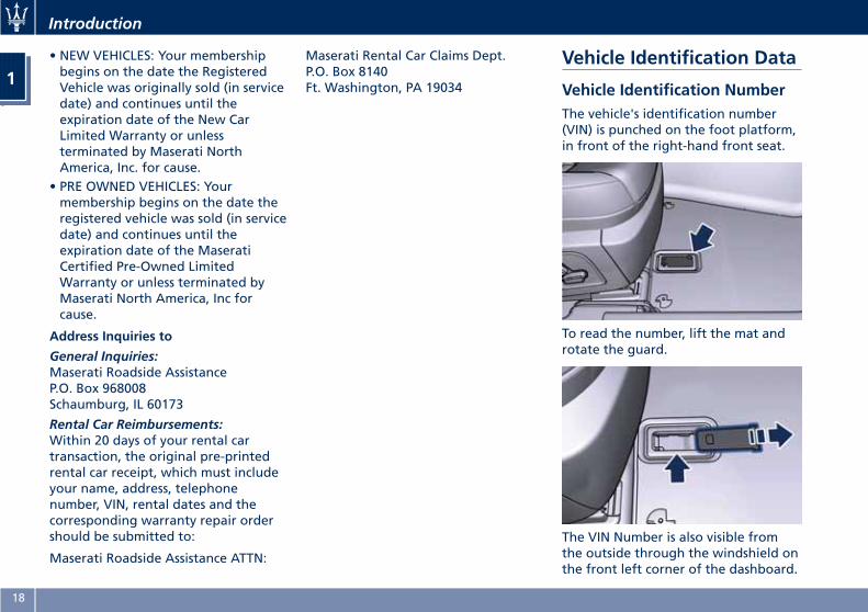
Vehicle Identification NumberThe vehicle's identification number(VIN) is punched on the foot platform,in front of the right-hand front seat.
To read the number, lift the mat androtate the guard.
The VIN Number is also visible fromthe outside through the windshield onthe front left corner of the dashboard.
Introduction
1
18
NOTE:
When ordering spare parts or makinginquiries, always quote the vehicleidentification number.
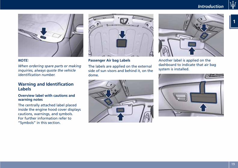
Warning and IdentificationLabelsOverview label with cautions andwarning notes
The centrally attached label placedinside the engine hood cover displayscautions, warnings, and symbols.For further information refer to“Symbols” in this section.
Passenger Air bag Labels
The labels are applied on the externalside of sun visors and behind it, on thedome.
Another label is applied on thedashboard to indicate that air bagsystem is installed.
Introduction
1
19

Danger Restart Engine with HoodOpen Label
The label is applied on the lower rightside of the hood.
Loading Information Label
This label applied on the driver's siderear door pillar attests the compliancewith safety standards.
Tire Information Label
This paper label is applied on thedriver's side rear door pillar.
NOTE:
For further informations see “TireSafety Information” in section"Driving".
Paint Identification Label
The label is applied on the lower leftside of the hood.
Fuel Warning Label
The label is applied inside the fuelfiller door.
NOTE:
To ensure optimum performance andfuel economy, please ensure to refillyour vehicle using Premium UnleadedFuel ONLY, with a minimum of 91 AKI.
Introduction
1
20
2 – Before Starting
Keys . . . . . . . . . . . . . . . . . . . . . . . . . . . . . . . . . . . . . . . . . . . . . . . . . . 22Sentry Key Immobilizer System . . . . . . . . . . . . . . . . . . . . . . . . . . . . . 24Vehicle Security Alarm . . . . . . . . . . . . . . . . . . . . . . . . . . . . . . . . . . . . 26Illuminated Entry/Exit . . . . . . . . . . . . . . . . . . . . . . . . . . . . . . . . . . . . 28Unlock the Vehicle with Key fob . . . . . . . . . . . . . . . . . . . . . . . . . . . . 31Requiring and Setting Additional Key fobs . . . . . . . . . . . . . . . . . . . . 33Remote Start System . . . . . . . . . . . . . . . . . . . . . . . . . . . . . . . . . . . . . 35Doors Locking . . . . . . . . . . . . . . . . . . . . . . . . . . . . . . . . . . . . . . . . . . 38Passive Entry System . . . . . . . . . . . . . . . . . . . . . . . . . . . . . . . . . . . . . 40Power Windows . . . . . . . . . . . . . . . . . . . . . . . . . . . . . . . . . . . . . . . . . 45Rear Window . . . . . . . . . . . . . . . . . . . . . . . . . . . . . . . . . . . . . . . . . . . 47Trunk Lid Operation . . . . . . . . . . . . . . . . . . . . . . . . . . . . . . . . . . . . . 48Trunk Safety . . . . . . . . . . . . . . . . . . . . . . . . . . . . . . . . . . . . . . . . . . . 53Hood Operation . . . . . . . . . . . . . . . . . . . . . . . . . . . . . . . . . . . . . . . . 54Occupants Restraint Systems . . . . . . . . . . . . . . . . . . . . . . . . . . . . . . . 55Supplemental Restraint System (SRS) — Air Bags . . . . . . . . . . . . . . . . 63Child Restraint Systems . . . . . . . . . . . . . . . . . . . . . . . . . . . . . . . . . . . 71Transporting Pets . . . . . . . . . . . . . . . . . . . . . . . . . . . . . . . . . . . . . . . . 76Rear Parking Camera . . . . . . . . . . . . . . . . . . . . . . . . . . . . . . . . . . . . . 76Surround View Camera System (optional) . . . . . . . . . . . . . . . . . . . . . 78Safety Tips . . . . . . . . . . . . . . . . . . . . . . . . . . . . . . . . . . . . . . . . . . . . . 81Park Assist (if equipped) . . . . . . . . . . . . . . . . . . . . . . . . . . . . . . . . . . 84
21
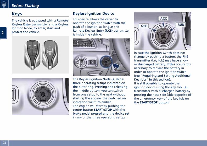
KeysThe vehicle is equipped with a RemoteKeyless Entry transmitter and a KeylessIgnition Node, to enter, start andprotect the vehicle.
Keyless Ignition DeviceThis device allows the driver tooperate the ignition switch with thepush of a button, as long as theRemote Keyless Entry (RKE) transmitteris inside the vehicle.
The Keyless Ignition Node (KIN) hasthree operating setups indicated onthe outer ring. Pressing and releasingthe middle button, you can switchfrom one setup to the next withoutstarting the engine, the switched onindication will turn amber.The engine will start by pushing thecenter button START/STOP with thebrake pedal pressed and the device setin any of the three operating setups.
In case the ignition switch does notchange by pushing a button, the RKEtransmitter (key fob) may have a lowor discharged battery. If this occurs it isnecessary to replace the battery inorder to operate the ignition switch(see “Requiring and Setting AdditionalKey fobs” in this section).It is still possible to operate theignition device using the key fob RKEtransmitter with discharged battery bypressing the nose side (side opposite ofthe emergency key) of the key fob onthe START/STOP button.
Before Starting
2
22
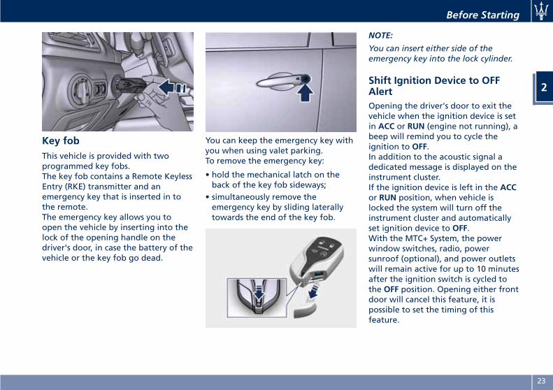
Key fobThis vehicle is provided with twoprogrammed key fobs.The key fob contains a Remote KeylessEntry (RKE) transmitter and anemergency key that is inserted in tothe remote.The emergency key allows you toopen the vehicle by inserting into thelock of the opening handle on thedriver's door, in case the battery of thevehicle or the key fob go dead.
You can keep the emergency key withyou when using valet parking.To remove the emergency key:
• hold the mechanical latch on theback of the key fob sideways;
• simultaneously remove theemergency key by sliding laterallytowards the end of the key fob.
NOTE:
You can insert either side of theemergency key into the lock cylinder.
Shift Ignition Device to OFFAlertOpening the driver's door to exit thevehicle when the ignition device is setin ACC or RUN (engine not running), abeep will remind you to cycle theignition to OFF.In addition to the acoustic signal adedicated message is displayed on theinstrument cluster.If the ignition device is left in the ACCor RUN position, when vehicle islocked the system will turn off theinstrument cluster and automaticallyset ignition device to OFF.With the MTC+ System, the powerwindow switches, radio, powersunroof (optional), and power outletswill remain active for up to 10 minutesafter the ignition switch is cycled tothe OFF position. Opening either frontdoor will cancel this feature, it ispossible to set the timing of thisfeature.
Before Starting
2
23
NOTE:
Refer to “MTC+ Settings” in Section“Dashboard Instruments and Controls”for further information.
WARNING!•When leaving the vehicle, alwaysremove the key fob and lock yourvehicle.
• Do not allow children to be in avehicle unattended or with access toan unlocked vehicle. A child orothers could be seriously or fatallyinjured. Children should be warnednot to touch the parking braketrigger, brake pedal or the shiftlever.
• Do not leave the key fob in or nearthe vehicle, and do not leave theignition switch in the ACC or RUNmode. A child could operate powerwindows, other controls, or movethe vehicle.
• Do not leave children or animalsinside parked vehicles in hotweather. Interior heat build-up maycause serious injury or death.
• An unlocked car is an invitation tothieves. Always remove the key fobfrom vehicle, cycle the ignition
switch to OFF and lock all doorswhen leaving the vehicleunattended.
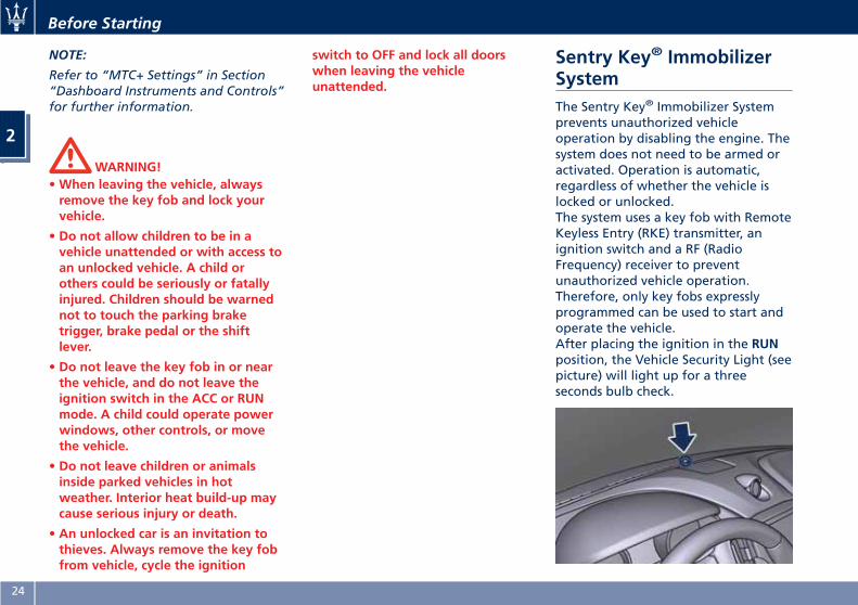
Sentry Key® ImmobilizerSystemThe Sentry Key® Immobilizer Systemprevents unauthorized vehicleoperation by disabling the engine. Thesystem does not need to be armed oractivated. Operation is automatic,regardless of whether the vehicle islocked or unlocked.The system uses a key fob with RemoteKeyless Entry (RKE) transmitter, anignition switch and a RF (RadioFrequency) receiver to preventunauthorized vehicle operation.Therefore, only key fobs expresslyprogrammed can be used to start andoperate the vehicle.After placing the ignition in the RUNposition, the Vehicle Security Light (seepicture) will light up for a threeseconds bulb check.
Before Starting
2
24
If the light remains on after the bulbcheck, it indicates that there is aproblem with the electronics: thiscondition will result in the enginebeing shut off after two seconds.If the Vehicle Security Light turns onduring normal vehicle operation(engine running for longer than 10seconds), an electronic fault isdetected. Should this occur, contactthe Authorized Maserati Dealer assoon as possible for assistance.
CAUTION!The Sentry Key® Immobilizer system isnot compatible with some remotestarting systems that can be installedin after-market.
Use of these systems may result invehicle starting problems and loss ofsecurity protection.
All key fobs provided with the newvehicle have been updated with thevehicle electronics and are thereforeable to guarantee correct functioningand protection.
General InformationThis device complies with Part 15 ofthe FCC rules and RSS 210 of IndustryCanada.
Operation is subject to the followingconditions:
• This device may not cause harmfulinterference.
• This device must accept anyinterference that may be received,including interference that maycause undesired operation.
Replacement Key fobs
NOTE:
Only key fobs that are updated withthe vehicle electronics can be used tostart and operate the vehicle.
WARNING!• Always remove the key fobs fromthe vehicle and lock all doors whenleaving the vehicle unattended.
• Always remember to cycle theignition switch to OFF.
Duplication of key fobs may beperformed by an Authorized MaseratiDealer only.This procedure consists ofprogramming a key fob that has neverbeen programmed to the vehicle’selectronics.
NOTE:
•When having the Sentry Key®
Immobilizer System serviced, bringall key fobs provided with thevehicle with you to the AuthorizedMaserati Dealer.
•When selling the vehicle, it isnecessary to provide the new ownerwith all key fobs.
Before Starting
2
25
Vehicle Security AlarmThe vehicle security alarm monitors thevehicle doors and trunk forunauthorized entry and theSTART/STOP button for unauthorizedoperations.The system includes a dual functionanti-intrusion sensor and vehicleanti-lift sensor. The anti-intrusionsensor monitors the vehicle interior formotion.The vehicle anti-lift sensor monitorsthe vehicle for any lifting or tiltingactions (tow away, tire removal, ferrytransport, etc). A siren with batterybackup which senses interruptions ofpower and communications is alsoincluded.While the vehicle security alarm isenabled, interior door locks switches,trunk lid and fuel filler door releaseare disabled. If something triggers thealarm, the vehicle security alarm willprovide the following audible andvisible signals: intermittent buzzer,position lights and/or turn signals andthe vehicle security light on thedashboard will flash.This light will fast flash forapproximately 15 seconds, when thevehicle security alarm is being armed,
and will then flash slowly until thevehicle is disarmed.
Rearming the SystemIf something triggers the securityalarm, and no quick action is taken todisarm it, the vehicle security alarmwill turn off the beeper after 29seconds, and turn off all of the visualsignals after 31 more seconds; thevehicle security alarm will then rearmitself.
Arming the SystemFollow these steps to arm the vehiclesecurity alarm.
• Make sure the vehicle ignition switchis OFF.
• Perform one of the followingmethods to lock the vehicle:
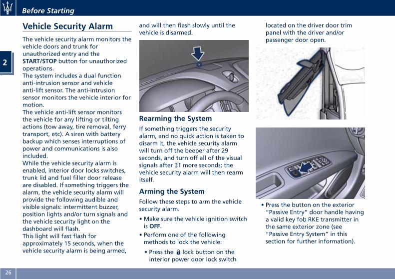
• Press the lock button on theinterior power door lock switch
located on the driver door trimpanel with the driver and/orpassenger door open.
• Press the button on the exterior“Passive Entry” door handle havinga valid key fob RKE transmitter inthe same exterior zone (see“Passive Entry System” in thissection for further information).
Before Starting
2
26
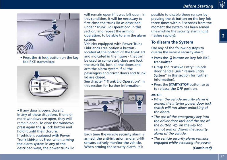
• Press the lock button on the keyfob RKE transmitter.
• If any door is open, close it.In any of these situations, if one ormore windows are open, they willremain open. To close the windowspress again the lock button andhold it until their closure.If vehicle is equipped with PowerTrunk Lid/Hands Free, when armingthe alarm system in any of thedescribed ways, the power trunk lid
will remain open if it was left open. Inthis condition, it will be necessary tofirst close the trunk lid as describedunder "Trunk Lid Operation" in thissection, and repeat the armingoperation, to be able to arm the alarmsystem.Vehicles equipped with Power TrunkLid/Hands Free option a button -located at the bottom of the trunk lidand indicated in the figure - that canbe used to completely close and lockthe trunk lid, lock all the doors andarm the alarm system if all thepassengers and driver doors and trunklid are closed.See chapter “ Trunk Lid Operation” inthis section for further information.
Each time the vehicle security alarm isarmed, the anti-intrusion and anti-liftsensors actively monitor the vehicle.When arming the security alarm, it is
possible to disable these sensors bypressing the button on the key fobthree times within 5 seconds from themoment the system has been armed(meanwhile the security alarm lightflashes rapidly).
To disarm the SystemUse any of the following steps todisarm the vehicle security alarm.
• Press the button on key fob RKEtransmitter.
• Grasp the “Passive Entry” unlockdoor handle (see “Passive EntrySystem” in this section for furtherinformation).
• Press the START/STOP button so asto release the OFF position.
NOTE:•When the vehicle security alarm isarmed, the interior power door lockswitch will not allow unlocking ofthe doors.
• The use of the emergency key intothe driver door lock and the use ofthe button on the key fobcannot arm or disarm the securityalarm of the vehicle.
• The vehicle security alarm remainsengaged while accessing the power
(Continued)
Before Starting
2
27
(Continued)trunk lid. Pressing the buttonbetween the license plate lights willnot disarm the vehicle security alarm.If anyone enters the vehicle throughthe trunk lid and opens a door, thealarm will trigger.
The vehicle security alarm is designedto protect your vehicle; however, youcan create conditions where thesystem will give you a false alarm. Ifone of the previously described armingsequences has occurred, the vehiclesecurity alarm will arm regardless ofwhether you are in the vehicle or not.If you remain in the vehicle and open adoor, the alarm will activate. If thisoccurs, disarm the vehicle securityalarm.If the vehicle security alarm is armedand the battery becomes disconnected,the vehicle security alarm will remainarmed when the battery isreconnected; the exterior lights willflash, the buzzer will activate. If thisoccurs, disarm the vehicle securityalarm.
Tamper AlertIf something has triggered the vehiclesecurity alarm in your absence, thehorn will sound three times when you
disarm the vehicle security alarm.Check the vehicle for tampering.
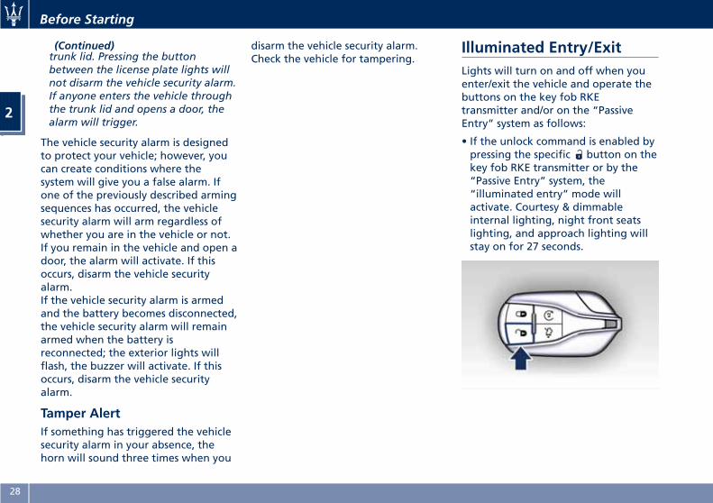
Illuminated Entry/ExitLights will turn on and off when youenter/exit the vehicle and operate thebuttons on the key fob RKEtransmitter and/or on the “PassiveEntry” system as follows:
• If the unlock command is enabled bypressing the specific button on thekey fob RKE transmitter or by the“Passive Entry” system, the“illuminated entry” mode willactivate. Courtesy & dimmableinternal lighting, night front seatslighting, and approach lighting willstay on for 27 seconds.
Before Starting
2
28
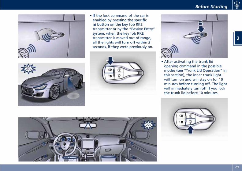
• If the lock command of the car isenabled by pressing the specific
button on the key fob RKEtransmitter or by the “Passive Entry”system, when the key fob RKEtransmitter is moved out of range,all the lights will turn off within 3seconds, if they were previously on.
• After activating the trunk lidopening command in the possiblemodes (see “Trunk Lid Operation” inthis section), the inner trunk lightwill turn on and will stay on for 10minutes before turning off. The lightwill immediately turn off if you lockthe trunk lid before 10 minutes.
Before Starting
2
29
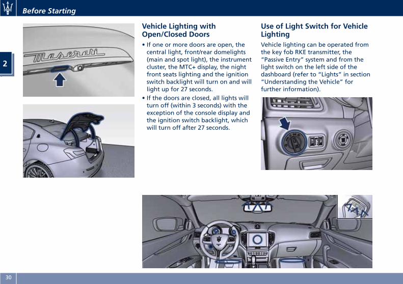
Vehicle Lighting withOpen/Closed Doors• If one or more doors are open, thecentral light, front/rear domelights(main and spot light), the instrumentcluster, the MTC+ display, the nightfront seats lighting and the ignitionswitch backlight will turn on and willlight up for 27 seconds.
• If the doors are closed, all lights willturn off (within 3 seconds) with theexception of the console display andthe ignition switch backlight, whichwill turn off after 27 seconds.
Use of Light Switch for VehicleLightingVehicle lighting can be operated fromthe key fob RKE transmitter, the“Passive Entry” system and from thelight switch on the left side of thedashboard (refer to “Lights” in section“Understanding the Vehicle” forfurther information).
Before Starting
2
30
• If the light switch is in the “0” (OFF)mode all switch backlights and thefront seats lighting will turn off.
• If the light switch is in theposition and the ignition switch
is in OFF position, the front lowintensity LEDs of the external lightand rear position light guide LEDwill turn on and will turn offautomatically after 8 minutes topreserve the battery charge.
• If the light switch is in positionand the ignition switch is in RUNposition, no lighting feature will beavailable.
• If the light switch is in position(Low beam mode) the frontdomelight LED (if enabled), theswitches backlighting, theinstrument cluster’s display, the nightfront seats lighting will turn on. Thefront domelight LED and the nightlighting of the front seats will lightup with the intensity set by theright-hand regulator. If the regulatoris in "0" (OFF) position, the nightlighting will turn off.
• If the light switch is turned in“AUTO” position (on/off AUTOmode) and the ignition is switched inRUN position, as in “low beammode” all lights turn on either in
“DAY” or “NIGHT” mode accordingto the twilight sensor. In “DAY”mode the switches backlighting willbe at 100% intensity, in “NIGHT”mode they will be as set by the leftdimmer control switch.
NOTE:
In “DAY” mode, the switches are notbacklit, except the windows andsteering switches.
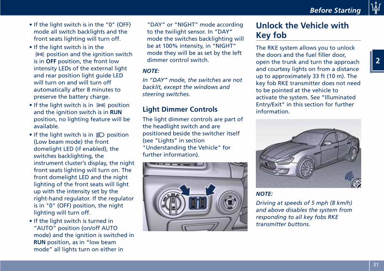
Light Dimmer ControlsThe light dimmer controls are part ofthe headlight switch and arepositioned beside the switcher itself(see “Lights” in section"Understanding the Vehicle" forfurther information).
Unlock the Vehicle withKey fobThe RKE system allows you to unlockthe doors and the fuel filler door,open the trunk and turn the approachand courtesy lights on from a distanceup to approximately 33 ft (10 m). Thekey fob RKE transmitter does not needto be pointed at the vehicle toactivate the system. See “IlluminatedEntry/Exit” in this section for furtherinformation.
NOTE:
Driving at speeds of 5 mph (8 km/h)and above disables the system fromresponding to all key fobs RKEtransmitter buttons.
Before Starting
2
31
Unlock the Doors, Fuel FillerDoor and TrunkPress and release the unlock button
on the key fob RKE transmitter onceto unlock the driver's door or twicewithin five seconds to unlock all doors,the fuel filler door and the trunk lid.The turn signal lights will flash for theunlock signal recognition. Theilluminated entry/exit system will alsoturn on. See “Passive Entry System” inthis section for further information.
Unlock Driver Door/All Doors withRemote Key 1st Press
This feature allows you to program thesystem to unlock either the driver'sdoor or all doors, the fuel filler doorand the trunk lid, by the first press ofthe unlock button on the key fobRKE transmitter. To change the currentsetting, see “MTC+ Settings” in section“Dashboard Instruments andControls”.
Lock/Unlock Doors Flash Lights
This feature will cause the flash of theturn signal lights when the doors arelocked or unlocked with the key fobRKE transmitter. This feature can beturned on or turned off. To change thecurrent setting, see “MTC+ Settings” in
section “Dashboard Instruments andControls”.
Turn Headlights On with Remote key
This feature activates the headlightsfor up to 90 seconds when the doorsare unlocked with the key fob RKEtransmitter. The duration can be set asdesired. To change the current setting,see “MTC+ Settings” in section“Dashboard Instruments andControls”.
Locking Doors Sound AlarmThis feature will cause the alarm toactivate when the doors are lockedwith the key fob RKE transmitter. Thisfeature can be enabled or disabled. Tochange the current setting, see “MTC+Settings” in section “DashboardInstruments and Controls”.
Unlatch the Trunk LidPress the button on the key fobRKE transmitter two times within fiveseconds to unlatch the manual trunklid.If the vehicle is equipped with PowerTrunk Lid/Hands Free, besidesunlocking the trunk lid, the controlwill fully open it.
See chapters “Passive Entry System”and “Trunk Lid Operation” in thissection for further information.
Before Starting
2
32
Requiring and SettingAdditional Key fobsProvide your Authorized MaseratiDealer the following when orderingadditional key fob RKE transmitters:
• all key fobs RKE transmitters in yourpossession;
• a personal ID;• the identification and registrationdocuments proving ownership of thevehicle.
Setting new key fobs or re-setting theoriginal ones can only be performedat an Authorized Maserati Dealer.
NOTE:
Codes of any key fob RKE transmittersthat are not present when the newsetting procedure is done will bedeleted from the memory to preventlost or stolen key fobs transmittersbeing used to disarm the electronicalarm system.
Key fob Battery Replacement
NOTE:
A low charge level of the key fobbattery will be indicated on theinstrument cluster display.
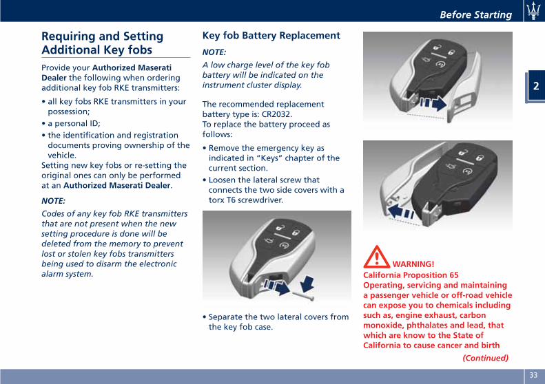
The recommended replacementbattery type is: CR2032.To replace the battery proceed asfollows:
• Remove the emergency key asindicated in “Keys” chapter of thecurrent section.
• Loosen the lateral screw thatconnects the two side covers with atorx T6 screwdriver.
• Separate the two lateral covers fromthe key fob case.
WARNING!California Proposition 65Operating, servicing and maintaininga passenger vehicle or off-road vehiclecan expose you to chemicals includingsuch as, engine exhaust, carbonmonoxide, phthalates and lead, thatwhich are know to the State ofCalifornia to cause cancer and birth
(Continued)
Before Starting
2
33
(Continued)defects or other reproductive harm. Tominimize exposure, avoid breathingexhaust, do not idle the engine exceptas necessary, service your vehicle in awell-ventilated area and wear glovesor wash your hands frequently whenservicing your vehicle. For moreinformation go to:www.P65Warnings.ca.gov/passenger-vehicle
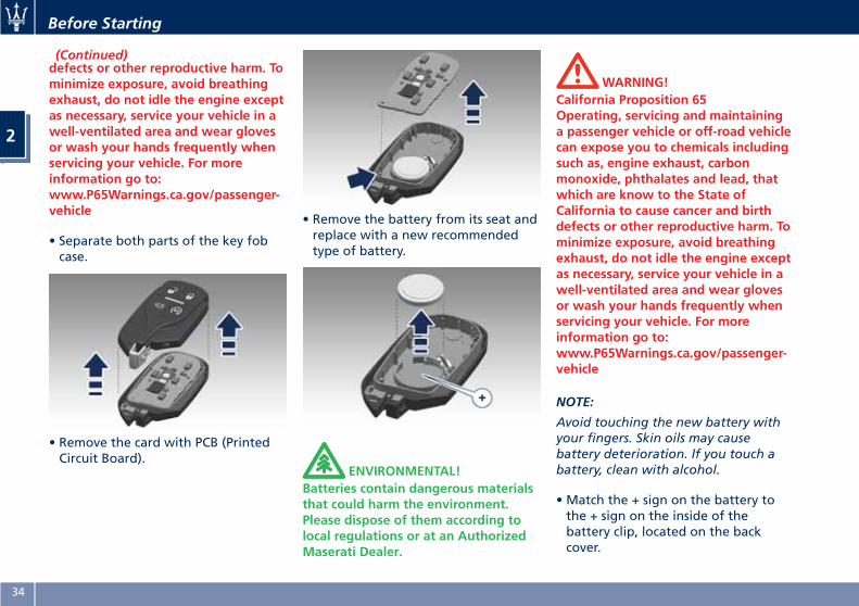
• Separate both parts of the key fobcase.
• Remove the card with PCB (PrintedCircuit Board).
• Remove the battery from its seat andreplace with a new recommendedtype of battery.
ENVIRONMENTAL!Batteries contain dangerous materialsthat could harm the environment.Please dispose of them according tolocal regulations or at an AuthorizedMaserati Dealer.
WARNING!California Proposition 65Operating, servicing and maintaininga passenger vehicle or off-road vehiclecan expose you to chemicals includingsuch as, engine exhaust, carbonmonoxide, phthalates and lead, thatwhich are know to the State ofCalifornia to cause cancer and birthdefects or other reproductive harm. Tominimize exposure, avoid breathingexhaust, do not idle the engine exceptas necessary, service your vehicle in awell-ventilated area and wear glovesor wash your hands frequently whenservicing your vehicle. For moreinformation go to:www.P65Warnings.ca.gov/passenger-vehicle
NOTE:
Avoid touching the new battery withyour fingers. Skin oils may causebattery deterioration. If you touch abattery, clean with alcohol.
• Match the + sign on the battery tothe + sign on the inside of thebattery clip, located on the backcover.
Before Starting
2
34
• Replace the printed circuit board byusing the indicated pin for thesealing of the two covers.
• Assemble the key fob case andreassemble the two lateral covers: aclick will indicate successful sealing.
• Combine the disassembled partswith clamping screw and reassemblethe emergency key.
Radio Frequency RKETransmitter - GeneralInformationThis device complies with Part 15 ofthe FCC rules and RSS 210 of IndustryCanada.The current device feature is subject tofollowing conditions:
• This device may not cause harmfulinterference.
• This device must accept anyinterference received, includinginterference that may causeundesired operation.
If your key fob RKE transmitter fails tooperate from a normal distance, checkfor these two conditions:
• A weak battery in the key fob RKEtransmitter. The expected life of thebattery in normal use is a minimumof three years.
• Closeness to a radio transmitter suchas a radio station tower, airporttransmitter, and some mobile or CBradios.
Remote Start SystemThis system enables the key fob RKEtransmitter to start the engineconveniently from outside the vehiclewhile still maintaining security. Thesystem has a range of approximately300 ft (91 m). Obstructions betweenthe vehicle and the key fob mayreduce this range.
General InformationThis device complies with Part 15 ofthe FCC rules and RSS 210 of IndustryCanada. Operation is subject to thefollowing conditions:
• This device may not cause harmfulinterference.
• This device must accept anyinterference received, includinginterference that may causeundesired operation.
NOTE:
Changes or modifications notexpressly approved by the partyresponsible for compliance could voidthe user's authority to operate theequipment.
If your RKE transmitter fails to operatefrom a normal distance, check forthese conditions:
Before Starting
2
35
• A weak battery in the RKEtransmitter. The expected life of thebattery is a minimum of three years.
• Closeness to a radio transmitter suchas a radio station tower, airporttransmitter, and some mobile or CBradio.
• Obstructions between the vehicleand the Key Fob.
How to use Remote StartAll of the following conditions must bemet before the engine will remotestart:
• System not disabled from previousremote start event.
• Vehicle theft alarm not active.• Doors closed.• Hood closed.• Power trunk lid closed.• Hazard lights switched off.• Brake pedal not pressed by anypassenger remained in the vehicle.
• Battery at an acceptable charge level.• The shift lever is in P (Park) position.• The vehicle transmission is inautomatic mode.
• The remote start has not beenactivated yet two consecutive times.
WARNING!• Do not start or run an engine in aclosed garage or confined area.Exhaust gas contains CarbonMonoxide (CO) which is odourlessand colourless
• Keep key fobs RKE transmitter awayfrom children. Operation of theRemote Start System, windows, doorlocks or other controls could causeserious injury or death.
Engine Remote Start AbortMessage on Instrument ClusterThe following messages will display onthe instrument cluster if the vehiclefails to remote start or exits remotestart prematurely:
• “Remote Start Canceled Door Open”.• “Remote Start Canceled TrunkOpen”.
• “Remote Start Canceled Fuel Low”.• “Remote Start Canceled TimeExpired”.
• “Remote Start Disabled Start Vehicleto Reset”.
The message on the instrument clusterstays active as long as the ignitionswitch is in RUN position.
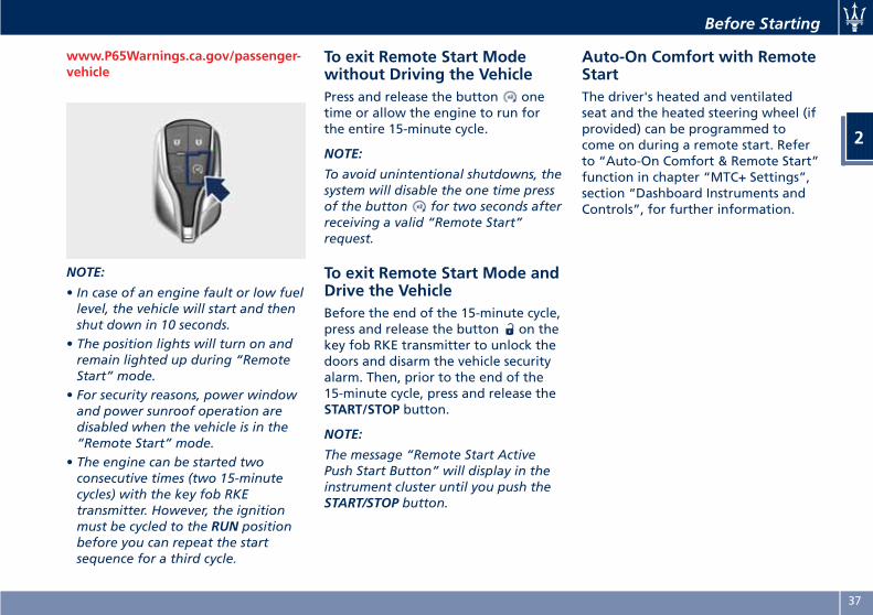
To enter Remote Start ModePress and release the button on thekey fob RKE transmitter twice withinfive seconds. The vehicle doors willlock, position lights will flash and thehorn will ring twice (if this function isset using the MTC+ System, refer to“MTC+ Settings” in section“Dashboard Instruments andControls”). Then, the engine will startand the vehicle will remain in the“Remote Start” mode for a 15-minutecycle.
WARNING!California Proposition 65Operating, servicing and maintaininga passenger vehicle or off-road vehiclecan expose you to chemicals includingsuch as, engine exhaust, carbonmonoxide, phthalates and lead, thatwhich are know to the State ofCalifornia to cause cancer and birthdefects or other reproductive harm. Tominimize exposure, avoid breathingexhaust, do not idle the engine exceptas necessary, service your vehicle in awell-ventilated area and wear glovesor wash your hands frequently whenservicing your vehicle. For moreinformation go to:
Before Starting
2
36
www.P65Warnings.ca.gov/passenger-vehicle
NOTE:
• In case of an engine fault or low fuellevel, the vehicle will start and thenshut down in 10 seconds.
• The position lights will turn on andremain lighted up during “RemoteStart” mode.
• For security reasons, power windowand power sunroof operation aredisabled when the vehicle is in the“Remote Start” mode.
• The engine can be started twoconsecutive times (two 15-minutecycles) with the key fob RKEtransmitter. However, the ignitionmust be cycled to the RUN positionbefore you can repeat the startsequence for a third cycle.
To exit Remote Start Modewithout Driving the VehiclePress and release the button onetime or allow the engine to run forthe entire 15-minute cycle.
NOTE:
To avoid unintentional shutdowns, thesystem will disable the one time pressof the button for two seconds afterreceiving a valid “Remote Start”request.
To exit Remote Start Mode andDrive the VehicleBefore the end of the 15-minute cycle,press and release the button on thekey fob RKE transmitter to unlock thedoors and disarm the vehicle securityalarm. Then, prior to the end of the15-minute cycle, press and release theSTART/STOP button.
NOTE:
The message “Remote Start ActivePush Start Button” will display in theinstrument cluster until you push theSTART/STOP button.
Auto-On Comfort with RemoteStartThe driver's heated and ventilatedseat and the heated steering wheel (ifprovided) can be programmed tocome on during a remote start. Referto “Auto-On Comfort & Remote Start”function in chapter “MTC+ Settings”,section “Dashboard Instruments andControls”, for further information.
Before Starting
2
37
Doors Locking
WARNING!• For personal security and safety inthe event of an accident or robbery,lock the vehicle doors before youdrive as well as when parking andleaving the vehicle unattended.
•When leaving the vehicle, alwaysremove the key fob RKE transmitterand lock your vehicle.
• Never leave children alone in avehicle, or with access to anunlocked vehicle.
• Do not allow children to be in avehicle unattended. A child or otherscould be seriously or fatally injured.Children must not touch the parkingbrake trigger, brake pedal or theshift lever.
• Do not leave the key fob in or nearthe vehicle, and do not leaveignition switch in the ACC or RUNmode. A child could operate powerwindows, other controls, or start theengine and the vehicle.
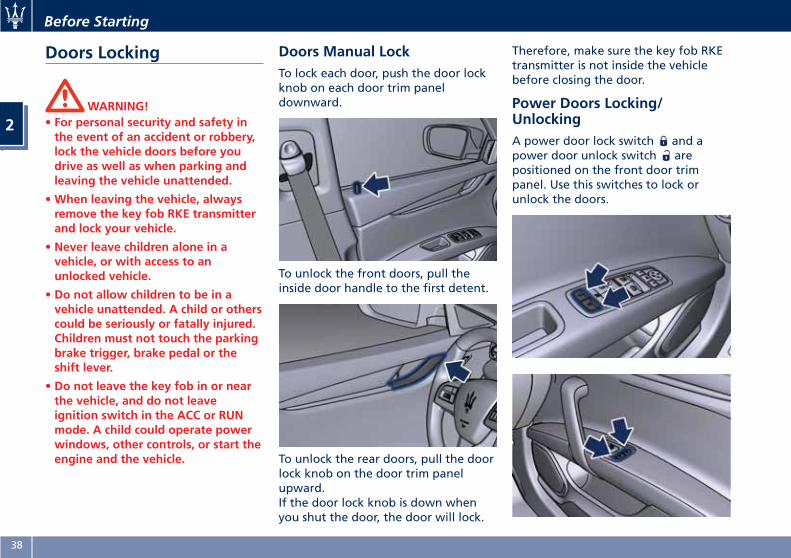
Doors Manual LockTo lock each door, push the door lockknob on each door trim paneldownward.
To unlock the front doors, pull theinside door handle to the first detent.
To unlock the rear doors, pull the doorlock knob on the door trim panelupward.If the door lock knob is down whenyou shut the door, the door will lock.
Therefore, make sure the key fob RKEtransmitter is not inside the vehiclebefore closing the door.
Power Doors Locking/UnlockingA power door lock switch and apower door unlock switch arepositioned on the front door trimpanel. Use this switches to lock orunlock the doors.
Before Starting
2
38
If the vehicle has been locked frominside with the above-figuredswitches, the fuel filler flap remainsunlocked.If Power Trunk Lid/ Hands Free (ifequipped) has been left open, it willstay open when you press lock button
, and the locking feature will onlyoccur after the closing of the powertrunk lid.The doors can also be locked andunlocked with the “Passive Entry”system. For further information, see“Passive Entry System” in this section.If you press the power door lockswitch while the ignition switch is inthe ACC or RUN position, and anyfront door is open, the power lockswill not operate. This prevents youfrom accidentally locking the key fobRKE transmitter in the vehicle.Cycling the ignition to the OFFposition or closing the door will allowthe locks of the doors and fuel fillerdoor to operate. If a door is open withthe key fob RKE transmitter inside thecabin and the ignition is in the ACC orRUN position, a beep will draw thedriver’s attention.
Automatic Locking Doors
The auto door lock feature defaultcondition is disabled. When enabled,
the door locks will lock automaticallywhen the vehicle's speed exceeds15 mph (24 km/h). The auto door lockfeature can be enabled or disabled byan Authorized Maserati Dealer onlywhich can also service the vehicle.
Automatic Door Unlock on Exit
The doors will unlock automatically onvehicles with power door locks if:
• The automatic unlock doors on exitfeature is enabled.
• The transmission is in gear and thevehicle speed is 0 (mph - km/h).
• The transmission is in N (Neutral) orP (Park).
• The driver door is open.• The doors were not previouslyunlocked.
• The vehicle speed is 0 (mph - km/h).
Set Automatic Door Unlock on Exit
To change the current setting, see“MTC+ Settings” in section“Dashboard Instruments andControls”.
NOTE:
Use the automatic door unlock on exitfeature in accordance with localregulations.
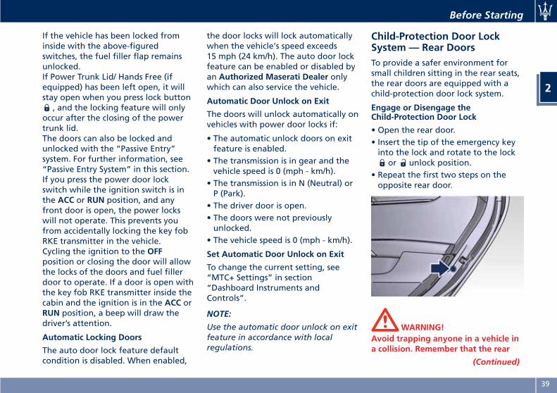
Child-Protection Door LockSystem — Rear DoorsTo provide a safer environment forsmall children sitting in the rear seats,the rear doors are equipped with achild-protection door lock system.
Engage or Disengage theChild-Protection Door Lock
• Open the rear door.• Insert the tip of the emergency keyinto the lock and rotate to the lock
or unlock position.• Repeat the first two steps on theopposite rear door.
WARNING!Avoid trapping anyone in a vehicle ina collision. Remember that the rear
(Continued)
Before Starting
2
39
(Continued)doors can only be opened from theoutside when the child-protectionlocks are engaged (locked).
NOTE:
For emergency exit from the rear seatswhen the child-protection door locksystem is engaged, manually raise thedoor lock knob to the unlockedposition, roll down the window, andopen the door using the outside doorhandle.
Soft Door Close System(optional)This system makes doors easier to shutwithout having to slam if you do notget it closed the first time. It increasesthe vehicle's safety and comfort, inparticular for children in the back seat,it is not necessary to slam the door andit also prevents the risk of travelingwith the door ajar.The system uses a sensor to detect thedoor ajar and an electric actuator toclose it. The sensor detects yourattempt to close the door and oncethe latch catches the handle theelectric actuator pulls the door firmlybringing the door back in the fullyclosed position.
During the soft closing phase operatedby the system, it is possible tointervene manually by opening orclosing the door.If you are pushing the door hardenough to close just like a regular one,the system still works, but only tocheck whether the door is properlyclosed.
WARNING!The system works properly if the ajardoor has a gap , between exteriordoor panel surface and exteriorbodyshell surface in the latch area , ofmax 0.23 in (6 mm). In the presence ofhigher gap, the system is not able toclose the door with the risk oftravelling with the door notcompletely closed or even open.
Passive Entry SystemThe “Passive Entry” system is anenhancement to the vehicle’s RemoteKeyless Entry (RKE) system. Thisfeature allows you to lock and unlockthe vehicle’s door(s) without having topress the key fob RKE transmitter lockor unlock buttons.
NOTE:
• “Passive Entry” may be programmedto on/off; see “MTC+ Settings” insection “Dashboard Instruments andControls” for further information.
• If wearing gloves, or if it has beenraining on the “Passive Entry” doorhandle, the unlock sensitivity can beaffected, resulting in a slowerresponse time.
• Access to the vehicle using “PassiveEntry” system may not work properlyin case of interference caused byexternal sources such as metalobjects, mobile phones, overheadpower lines, antennas, etc. In thesecases, use the buttons of the key fobRKE transmitter to open and closethe vehicle or the emergency key,inserting it into the driver side doorlock.
Before Starting
2
40
• The “Passive Entry” system does notlock and unlock the doors directlyand immediately but with a slightdelay (about 2 seconds).
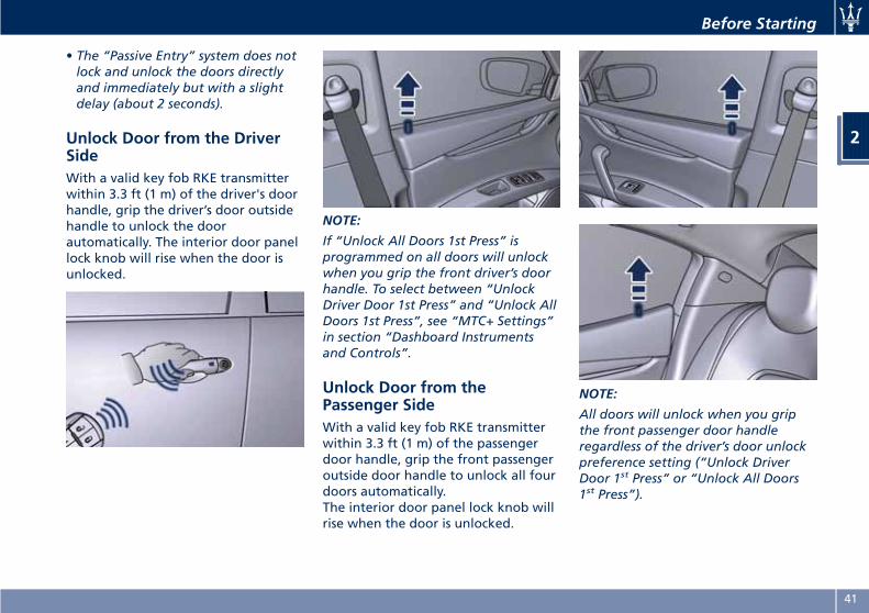
Unlock Door from the DriverSideWith a valid key fob RKE transmitterwithin 3.3 ft (1 m) of the driver's doorhandle, grip the driver’s door outsidehandle to unlock the doorautomatically. The interior door panellock knob will rise when the door isunlocked.
NOTE:
If “Unlock All Doors 1st Press” isprogrammed on all doors will unlockwhen you grip the front driver’s doorhandle. To select between “UnlockDriver Door 1st Press” and “Unlock AllDoors 1st Press”, see “MTC+ Settings”in section “Dashboard Instrumentsand Controls”.
Unlock Door from thePassenger SideWith a valid key fob RKE transmitterwithin 3.3 ft (1 m) of the passengerdoor handle, grip the front passengeroutside door handle to unlock all fourdoors automatically.The interior door panel lock knob willrise when the door is unlocked.
NOTE:
All doors will unlock when you gripthe front passenger door handleregardless of the driver’s door unlockpreference setting (“Unlock DriverDoor 1st Press” or “Unlock All Doors1st Press”).
Before Starting
2
41
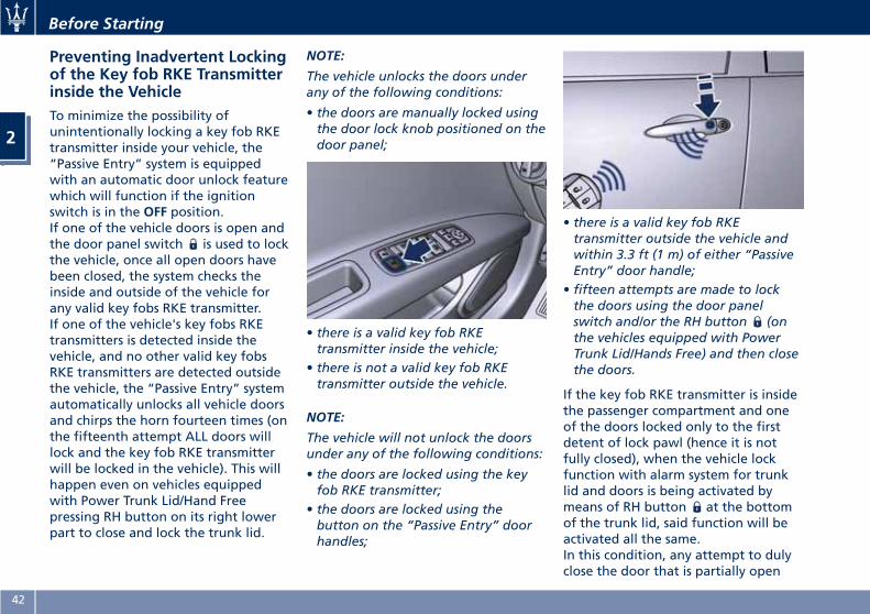
Preventing Inadvertent Lockingof the Key fob RKE Transmitterinside the VehicleTo minimize the possibility ofunintentionally locking a key fob RKEtransmitter inside your vehicle, the“Passive Entry” system is equippedwith an automatic door unlock featurewhich will function if the ignitionswitch is in the OFF position.If one of the vehicle doors is open andthe door panel switch is used to lockthe vehicle, once all open doors havebeen closed, the system checks theinside and outside of the vehicle forany valid key fobs RKE transmitter.If one of the vehicle's key fobs RKEtransmitters is detected inside thevehicle, and no other valid key fobsRKE transmitters are detected outsidethe vehicle, the “Passive Entry” systemautomatically unlocks all vehicle doorsand chirps the horn fourteen times (onthe fifteenth attempt ALL doors willlock and the key fob RKE transmitterwill be locked in the vehicle). This willhappen even on vehicles equippedwith Power Trunk Lid/Hand Freepressing RH button on its right lowerpart to close and lock the trunk lid.
NOTE:
The vehicle unlocks the doors underany of the following conditions:
• the doors are manually locked usingthe door lock knob positioned on thedoor panel;
• there is a valid key fob RKEtransmitter inside the vehicle;
• there is not a valid key fob RKEtransmitter outside the vehicle.
NOTE:
The vehicle will not unlock the doorsunder any of the following conditions:
• the doors are locked using the keyfob RKE transmitter;
• the doors are locked using thebutton on the “Passive Entry” doorhandles;
• there is a valid key fob RKEtransmitter outside the vehicle andwithin 3.3 ft (1 m) of either “PassiveEntry” door handle;
• fifteen attempts are made to lockthe doors using the door panelswitch and/or the RH button (onthe vehicles equipped with PowerTrunk Lid/Hands Free) and then closethe doors.
If the key fob RKE transmitter is insidethe passenger compartment and oneof the doors locked only to the firstdetent of lock pawl (hence it is notfully closed), when the vehicle lockfunction with alarm system for trunklid and doors is being activated bymeans of RH button at the bottomof the trunk lid, said function will beactivated all the same.In this condition, any attempt to dulyclose the door that is partially open
Before Starting
2
42
will cancel vehicle lock and alarmsystem arming thus leaving vehicleunlocked.Since when the doors are locked, the"Passive Entry" system waits for about16 seconds before verifying if a keyfob RKE transmitter is present insidethe vehicle.
Release the Lid and Enter theTrunkFor vehicles equipped with manualtrunk lid, with the key fob within 3.3ft (1 m) of the lid, press the buttonlocated between the licence platelights and lift it manually.For vehicles equipped with PowerTrunk Lid/Hands Free, with the key fobwithin 3.3 ft (1 m) of the lid, press thebutton located between the licenseplate lights, the power trunk lid willautomatically open until it hasreached its maximum height; if thesame button is not pressed again tostop it (for more information, seechapter “Trunk Lid Operation” in thissection).If the vehicle had already beenunlocked through key fob or “PassiveEntry”, the presence of the key fob isnot required; simply use the buttonlocated between the license plate
lights to open the trunk lid manuallyor automatically.
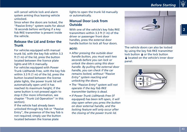
Manual Door Lock fromOutsideWith one of the vehicle’s key fobs RKEtransmitters within 3.3 ft (1 m) of thedriver or passenger front doorhandles, press the external doorhandle button to lock all four doors.
NOTE:
• After pressing the outside doorhandle button, you must wait twoseconds before you can lock orunlock the doors using this doorhandle. By pulling the external doorhandle, you can check if the carremains locked, without “PassiveEntry” system reacting andunlocking the doors.
• The “Passive Entry” system will notoperate if the key fob RKEtransmitter battery is dead.
• If Power Trunk Lid/Hands Free (ifequipped) has been left open, it willstay open when you press the buttonon door external handle, and thelocking feature will only occur afterthe closing of the power trunk lid.
The vehicle doors can also be lockedby using the key fob RKE transmitterlock button or the lock button
located on the vehicle’s inner doorpanel.
Before Starting
2
43
General InformationKey Fob (Keyless Enter-N-Go)
This device complies with Part 15 ofthe FCC Rules.Operation is subject to the followingtwo conditions:
• This device may not cause harmfulinterference.
• This device must accept anyinterference received, includinginterference that may causeundesired operation.
The device is covered by:Continental FCC ID: M3N-7393490.
Ignition device (Keyless Enter-N-Go)
This device complies with Part 15 ofthe FCC Rules.Operation is subject to the followingtwo conditions:
• This device may not cause harmfulinterference.
• This device must accept anyinterference received, includinginterference that may causeundesired operation.
The device is covered by:Continental FCC ID: OHT-40821803.
Control Unit (Keyless Enter-N-Go)
This device complies with Part 15 ofthe FCC Rules.Operation is subject to the followingtwo conditions:
• This device may not cause harmfulinterference.
• This device must accept anyinterference received, includinginterference that may causeundesired operation.
The device is covered by:Continental FCC ID: M3N-40821703.
Before Starting
2
44
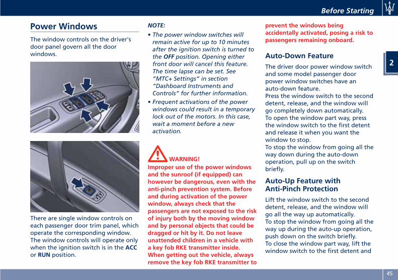
Power WindowsThe window controls on the driver'sdoor panel govern all the doorwindows.
There are single window controls oneach passenger door trim panel, whichoperate the corresponding window.The window controls will operate onlywhen the ignition switch is in the ACCor RUN position.
NOTE:
• The power window switches willremain active for up to 10 minutesafter the ignition switch is turned tothe OFF position. Opening eitherfront door will cancel this feature.The time lapse can be set. See“MTC+ Settings” in section“Dashboard Instruments andControls” for further information.
• Frequent activations of the powerwindows could result in a temporarylock out of the motors. In this case,wait a moment before a newactivation.
WARNING!Improper use of the power windowsand the sunroof (if equipped) canhowever be dangerous, even with theanti-pinch prevention system. Beforeand during activation of the powerwindow, always check that thepassengers are not exposed to the riskof injury both by the moving windowand by personal objects that could bedragged or hit by it. Do not leaveunattended children in a vehicle witha key fob RKE transmitter inside.When getting out the vehicle, alwaysremove the key fob RKE transmitter to
prevent the windows beingaccidentally activated, posing a risk topassengers remaining onboard.
Auto-Down FeatureThe driver door power window switchand some model passenger doorpower window switches have anauto-down feature.Press the window switch to the seconddetent, release, and the window willgo completely down automatically.To open the window part way, pressthe window switch to the first detentand release it when you want thewindow to stop.To stop the window from going all theway down during the auto-downoperation, pull up on the switchbriefly.
Auto-Up Feature withAnti-Pinch ProtectionLift the window switch to the seconddetent, release, and the window willgo all the way up automatically.To stop the window from going all theway up during the auto-up operation,push down on the switch briefly.To close the window part way, lift thewindow switch to the first detent and
Before Starting
2
45
release it when you want the windowto stop.
NOTE:
• If the window runs into any obstacleduring auto-closure, it will reversedirection and then go back down.Remove the obstacle and use thewindow switch again to close thewindow.
• Any impact due to rough roadconditions may trigger the autoreverse function unexpectedly duringauto-closure. If this happens, pull theswitch lightly to the first detent andhold to close the window manually.
• Frequent activations of theanti-pinch function could disable theauto-down and auto-up function ofthe windows. In order to re-activatethis function proceed with a resetcycle as described in the nextparagraph.
WARNING!There is no anti-pinch protection whenthe window is almost closed. Be sureto clear all objects from the areabefore closing the window.
Reset Auto-Up/DownShould the auto-up/down feature stopworking, the window probably needsto be reset.To reset auto-up/down, pull thewindow switch up to close the windowcompletely and push the windowswitch down to open the windowcompletely.
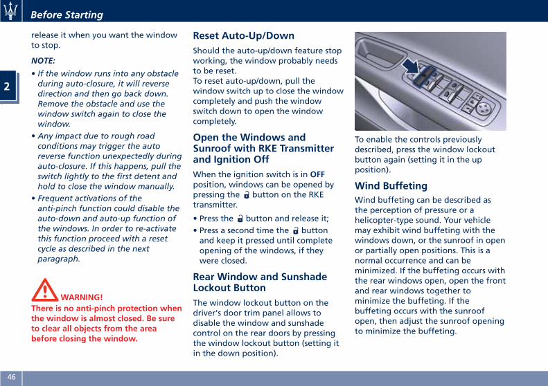
Open the Windows andSunroof with RKE Transmitterand Ignition OffWhen the ignition switch is in OFFposition, windows can be opened bypressing the button on the RKEtransmitter.
• Press the button and release it;• Press a second time the buttonand keep it pressed until completeopening of the windows, if theywere closed.
Rear Window and SunshadeLockout ButtonThe window lockout button on thedriver's door trim panel allows todisable the window and sunshadecontrol on the rear doors by pressingthe window lockout button (setting itin the down position).
To enable the controls previouslydescribed, press the window lockoutbutton again (setting it in the upposition).
Wind BuffetingWind buffeting can be described asthe perception of pressure or ahelicopter-type sound. Your vehiclemay exhibit wind buffeting with thewindows down, or the sunroof in openor partially open positions. This is anormal occurrence and can beminimized. If the buffeting occurs withthe rear windows open, open the frontand rear windows together tominimize the buffeting. If thebuffeting occurs with the sunroofopen, then adjust the sunroof openingto minimize the buffeting.
Before Starting
2
46
Rear Window
Rear Window DefrosterThe rear window defroster button islocated on the climate control panel.See “Air Conditioning Controls” insection “Dashboard Instruments andControls”.
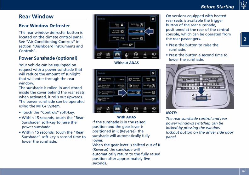
Power Sunshade (optional)Your vehicle can be equipped onrequest with a power sunshade thatwill reduce the amount of sunlightthat will enter through the rearwindow.The sunshade is rolled in and storedinside the cover behind the rear seats;when activated, it rolls out upwards.The power sunshade can be operatedusing the MTC+ System.
• Touch the “Controls” soft-key.• Within 15 seconds, touch the “RearSunshade” soft-key to raise thepower sunshade.
• Within 15 seconds, touch the “RearSunshade” soft-key a second time tolower the sunshade.
If the sunshade is in the raisedposition and the gear lever ispositioned in R (Reverse), thesunshade will automatically fullylower.When the gear lever is shifted out of R(Reverse) the sunshade willautomatically return to the fully raisedposition after approximately fiveseconds.
On versions equipped with heatedrear seats is available the triggerbutton of the rear sunshade,positioned at the rear of the centralconsole, which can be operated fromthe rear passengers.
• Press the button to raise thesunshade.
• Press the button a second time tolower the sunshade.
NOTE:
The rear sunshade control and rearpower windows switches, can belocked by pressing the windowlockout button on the driver side doorpanel.
Without ADAS
With ADAS
Before Starting
2
47
.
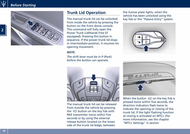
Trunk Lid OperationThe manual trunk lid can be unlockedfrom inside the vehicle by pressing thebutton on the front dome console.This command will fully open thePower Trunk Lid/Hands Free (ifequipped). Pressing this button insequence, if the power trunk lid stopsin intermediate position, it resumes hisopening movement.
NOTE:
The shift lever must be in P (Park)before the button can operate.
The manual trunk lid can be releasedfrom outside the vehicle by pressingthe button on the key fob withRKE transmitter twice within fiveseconds or by using the externalrelease button located on the lowerside of the trunk lid ledge, between
the license plate lights, when thevehicle has been unlocked using thekey fob or the “Passive Entry” system.
When the button on the key fob ispressed twice within five seconds, thedirection indicators flash twice toindicate the opening or closing of thetrunk lid, if the light flashing functionat closing is activated on MTC+ (formore information, see the chapter"MTC+ Settings" in section
Before Starting
2
48
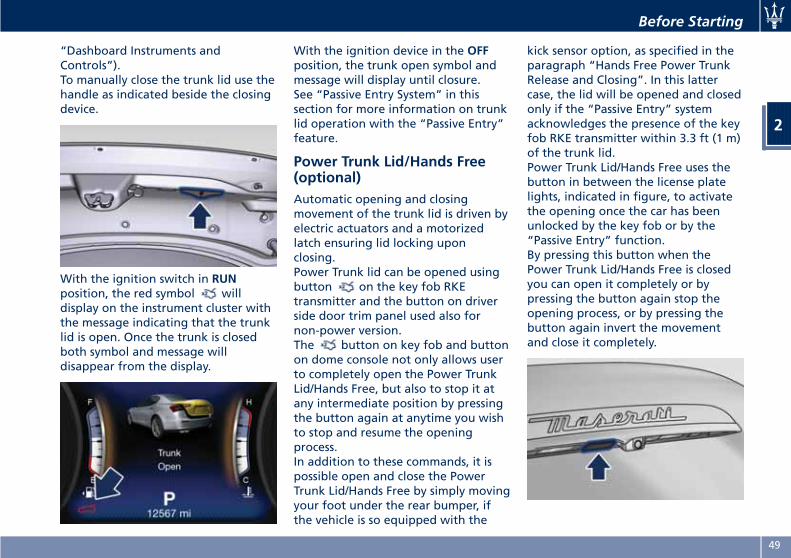
“Dashboard Instruments andControls”).To manually close the trunk lid use thehandle as indicated beside the closingdevice.
With the ignition switch in RUNposition, the red symbol willdisplay on the instrument cluster withthe message indicating that the trunklid is open. Once the trunk is closedboth symbol and message willdisappear from the display.
With the ignition device in the OFFposition, the trunk open symbol andmessage will display until closure.See “Passive Entry System” in thissection for more information on trunklid operation with the “Passive Entry”feature.
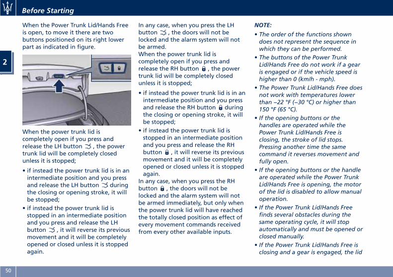
Power Trunk Lid/Hands Free(optional)Automatic opening and closingmovement of the trunk lid is driven byelectric actuators and a motorizedlatch ensuring lid locking uponclosing.Power Trunk lid can be opened usingbutton on the key fob RKEtransmitter and the button on driverside door trim panel used also fornon-power version.The button on key fob and buttonon dome console not only allows userto completely open the Power TrunkLid/Hands Free, but also to stop it atany intermediate position by pressingthe button again at anytime you wishto stop and resume the openingprocess.In addition to these commands, it ispossible open and close the PowerTrunk Lid/Hands Free by simply movingyour foot under the rear bumper, ifthe vehicle is so equipped with the
kick sensor option, as specified in theparagraph “Hands Free Power TrunkRelease and Closing”. In this lattercase, the lid will be opened and closedonly if the “Passive Entry” systemacknowledges the presence of the keyfob RKE transmitter within 3.3 ft (1 m)of the trunk lid.Power Trunk Lid/Hands Free uses thebutton in between the license platelights, indicated in figure, to activatethe opening once the car has beenunlocked by the key fob or by the“Passive Entry” function.By pressing this button when thePower Trunk Lid/Hands Free is closedyou can open it completely or bypressing the button again stop theopening process, or by pressing thebutton again invert the movementand close it completely.
Before Starting
2
49
When the Power Trunk Lid/Hands Freeis open, to move it there are twobuttons positioned on its right lowerpart as indicated in figure.
When the power trunk lid iscompletely open if you press andrelease the LH button , the powertrunk lid will be completely closedunless it is stopped;
• if instead the power trunk lid is in anintermediate position and you pressand release the LH button duringthe closing or opening stroke, it willbe stopped;
• if instead the power trunk lid isstopped in an intermediate positionand you press and release the LHbutton , it will reverse its previousmovement and it will be completelyopened or closed unless it is stoppedagain.
In any case, when you press the LHbutton , the doors will not belocked and the alarm system will notbe armed.When the power trunk lid iscompletely open if you press andrelease the RH button , the powertrunk lid will be completely closedunless it is stopped;
• if instead the power trunk lid is in anintermediate position and you pressand release the RH button duringthe closing or opening stroke, it willbe stopped;
• if instead the power trunk lid isstopped in an intermediate positionand you press and release the RHbutton , it will reverse its previousmovement and it will be completelyopened or closed unless it is stoppedagain.
In any case, when you press the RHbutton , the doors will not belocked and the alarm system will notbe armed immediately, but only whenthe power trunk lid will have reachedthe totally closed position as effect ofevery movement commands receivedfrom every other available inputs.
NOTE:
• The order of the functions showndoes not represent the sequence inwhich they can be performed.
• The buttons of the Power TrunkLid/Hands Free do not work if a gearis engaged or if the vehicle speed ishigher than 0 (km/h - mph).
• The Power Trunk Lid/Hands Free doesnot work with temperatures lowerthan −22 °F (−30 °C) or higher than150 °F (65 °C).
• If the opening buttons or thehandles are operated while thePower Trunk Lid/Hands Free isclosing, the stroke of lid stops.Pressing another time the samecommand it reverses movement andfully open.
• If the opening buttons or the handleare operated while the Power TrunkLid/Hands Free is opening, the motorof the lid is disabled to allow manualoperation.
• If the Power Trunk Lid/Hands Freefinds several obstacles during thesame operating cycle, it will stopautomatically and must be opened orclosed manually.
• If the Power Trunk Lid/Hands Free isclosing and a gear is engaged, the lid
Before Starting
2
50
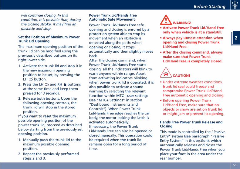
will continue closing. In thiscondition, it is possible that, duringthe closing stroke, it may find anobstacle and stop.
Set the Position of Maximum PowerTrunk Lid Opening
The maximum opening position of thetrunk lid can be modified using thepreviously described buttons on itsright lower side.
1. Activate the trunk lid and stop it inthe new maximum openingposition to be set, by pressing theLH button.
2. Press the LH and RH buttonsat the same time and keep thempressed for 3 seconds.
3. Release both buttons. Upon thefollowing opening controls, thetrunk lid will stop in the storedposition.
If you want to reset the maximumpossible opening position of thepower trunk lid, proceed as describedbelow starting from the previously setopening position.
1. Manually push the trunk lid to themaximum possible openingposition.
2. Repeat the previously performedsteps 2 and 3.
Power Trunk Lid/Hands FreeAutomatic Safe Movement
Power Trunk Lid/Hands Free safeopening and closing is ensured by aprotection system able to stop itsmovement when an obstacle isdetected along the path: whenopening or closing, it stopsautomatically and then slightly movesback.After the closing command, whenPower Trunk Lid/Hands Free startsclosing, all the indicators will blink towarn anyone within range. Apartfrom activating indicators blinkingwhen power trunk lid is operated, it isalso possible to activate a soundwarning by selecting the relevantfunction within MTC+ user settings(see “MTC+ Settings” in section“Dashboard Instruments andControls”). When Power TrunkLid/Hands Free edge reaches the carbody, the motor locking the latch isactivated automatically.If necessary, the Power TrunkLid/Hands Free can also be opened orclosed manually. This operation couldbe required when the trunk lidremains open for a long period oftime.
WARNING!• Activate Power Trunk Lid/Hand Freeonly when vehicle is at a standstill.
• Always pay utmost attention whenopening and closing Power TrunkLid/Hand Free.
• After the closing command, alwaysmake sure that Power TrunkLid/Hand Free is completely closed.
CAUTION!
• Under extreme weather conditions,trunk lid seal could freeze andcompromise Power Trunk Lid/HandFree automatic opening and closing.
• Before opening Power TrunkLid/Hand Free, make sure that noobjects or snow are set on trunk lidor might jam or prevent its opening.
Hands Free Power Trunk Release andClosing
This mode is controlled by the “PassiveEntry” system (see paragraph “PassiveEntry System” in this section), whichautomatically releases and closes thePower Trunk Lid/Hands Free when youplace your foot in the area under therear bumper.
Before Starting
2
51
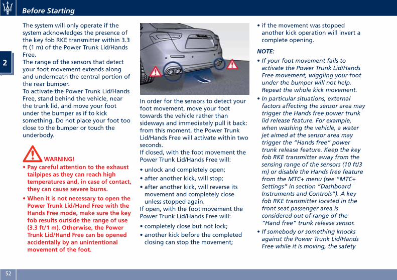
The system will only operate if thesystem acknowledges the presence ofthe key fob RKE transmitter within 3.3ft (1 m) of the Power Trunk Lid/HandsFree.The range of the sensors that detectyour foot movement extends alongand underneath the central portion ofthe rear bumper.To activate the Power Trunk Lid/HandsFree, stand behind the vehicle, nearthe trunk lid, and move your footunder the bumper as if to kicksomething. Do not place your foot tooclose to the bumper or touch theunderbody.
WARNING!• Pay careful attention to the exhausttailpipes as they can reach hightemperatures and, in case of contact,they can cause severe burns.
•When it is not necessary to open thePower Trunk Lid/Hand Free with theHands Free mode, make sure the keyfob results outside the range of use(3.3 ft/1 m). Otherwise, the PowerTrunk Lid/Hand Free can be openedaccidentally by an unintentionalmovement of the foot.
In order for the sensors to detect yourfoot movement, move your foottowards the vehicle rather thansideways and immediately pull it back:from this moment, the Power TrunkLid/Hands Free will activate within twoseconds.If closed, with the foot movement thePower Trunk Lid/Hands Free will:
• unlock and completely open;• after another kick, will stop;• after another kick, will reverse itsmovement and completely closeunless stopped again.
If open, with the foot movement thePower Trunk Lid/Hands Free will:
• completely close but not lock;• another kick before the completedclosing can stop the movement;
• if the movement was stoppedanother kick operation will invert acomplete opening.
NOTE:
• If your foot movement fails toactivate the Power Trunk Lid/HandsFree movement, wiggling your footunder the bumper will not help.Repeat the whole kick movement.
• In particular situations, externalfactors affecting the sensor area maytrigger the Hands free power trunklid release feature. For example,when washing the vehicle, a waterjet aimed at the sensor area maytrigger the “Hands free” powertrunk release feature. Keep the keyfob RKE transmitter away from thesensing range of the sensors (10 ft/3m) or disable the Hands free featurefrom the MTC+ menu (see “MTC+Settings” in section “DashboardInstruments and Controls”). A keyfob RKE transmitter located in thefront seat passenger area isconsidered out of range of the“Hand free” trunk release sensor.
• If somebody or something knocksagainst the Power Trunk Lid/HandsFree while it is moving, the safety
Before Starting
2
52
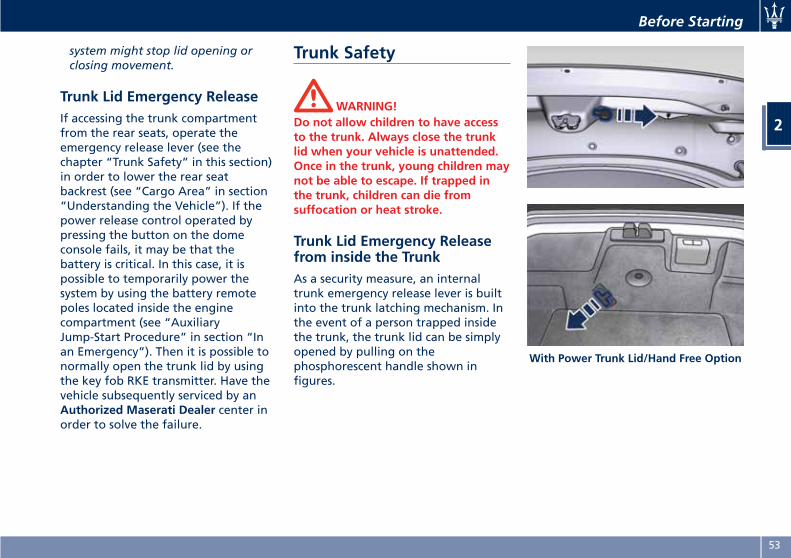
system might stop lid opening orclosing movement.
Trunk Lid Emergency ReleaseIf accessing the trunk compartmentfrom the rear seats, operate theemergency release lever (see thechapter “Trunk Safety” in this section)in order to lower the rear seatbackrest (see “Cargo Area” in section“Understanding the Vehicle”). If thepower release control operated bypressing the button on the domeconsole fails, it may be that thebattery is critical. In this case, it ispossible to temporarily power thesystem by using the battery remotepoles located inside the enginecompartment (see “AuxiliaryJump-Start Procedure” in section “Inan Emergency”). Then it is possible tonormally open the trunk lid by usingthe key fob RKE transmitter. Have thevehicle subsequently serviced by anAuthorized Maserati Dealer center inorder to solve the failure.
Trunk Safety
WARNING!Do not allow children to have accessto the trunk. Always close the trunklid when your vehicle is unattended.Once in the trunk, young children maynot be able to escape. If trapped inthe trunk, children can die fromsuffocation or heat stroke.
Trunk Lid Emergency Releasefrom inside the TrunkAs a security measure, an internaltrunk emergency release lever is builtinto the trunk latching mechanism. Inthe event of a person trapped insidethe trunk, the trunk lid can be simplyopened by pulling on thephosphorescent handle shown infigures.
With Power Trunk Lid/Hand Free Option
Before Starting
2
53
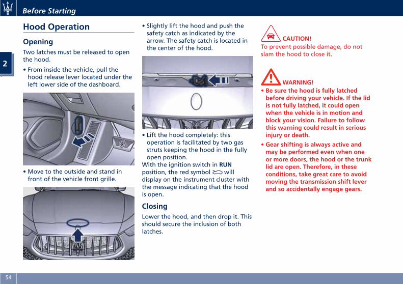
Hood Operation
OpeningTwo latches must be released to openthe hood.
• From inside the vehicle, pull thehood release lever located under theleft lower side of the dashboard.
• Move to the outside and stand infront of the vehicle front grille.
• Slightly lift the hood and push thesafety catch as indicated by thearrow. The safety catch is located inthe center of the hood.
• Lift the hood completely: thisoperation is facilitated by two gasstruts keeping the hood in the fullyopen position.
With the ignition switch in RUNposition, the red symbol willdisplay on the instrument cluster withthe message indicating that the hoodis open.
ClosingLower the hood, and then drop it. Thisshould secure the inclusion of bothlatches.
CAUTION!To prevent possible damage, do notslam the hood to close it.
WARNING!• Be sure the hood is fully latchedbefore driving your vehicle. If the lidis not fully latched, it could openwhen the vehicle is in motion andblock your vision. Failure to followthis warning could result in seriousinjury or death.
• Gear shifting is always active andmay be performed even when oneor more doors, the hood or the trunklid are open. Therefore, in theseconditions, take great care to avoidmoving the transmission shift leverand so accidentally engage gears.
Before Starting
2
54
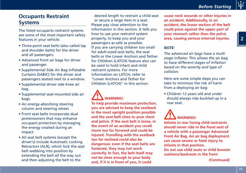
Occupants RestraintSystemsThe listed occupants restraint systemsare some of the most important safetyfeatures in your vehicle:
• Three-point seat belts (also called lapand shoulder belts) for the driverand all passengers.
• Advanced front air bags for driverand passenger.
• Supplemental Side Air Bag InflatableCurtains (SABIC) for the driver andpassengers seated next to a window.
• Supplemental driver side knee airbag.
• Supplemental seat-mounted side airbags.
• An energy-absorbing steeringcolumn and steering wheel.
• Front seat belts incorporate dualpretensioners that may enhanceoccupant protection by managingthe energy created during animpact.
• All seat belt systems (except thedriver’s) include Automatic LockingRetractors (ALR), which lock the seatbelt webbing into position byextending the belt all the way outand then adjusting the belt to the
desired length to restrain a child seator secure a large item in a seat.
Please pay close attention to theinformation in this section. It tells youhow to use your restraint systemproperly, to keep you and yourpassengers as safe as possible.If you are carrying children too smallfor adult-sized seat belts, the seatbelts or the Lower Anchors and Tetherfor CHildren (LATCH) feature also canbe used to hold infant and childrestraint systems. For moreinformation on LATCH, refer to“Lower Anchors and Tether forCHildren (LATCH)” in this section.
WARNING!To help provide maximum protection,you are advised to keep the seatbackin the most upright position possibleand the seat belt close to your chestand pelvis. If the seat belt is loose, inthe event of an accident you couldmove too far forward and could beinjured. Travelling with the seatbacktoo far reclined could also bedangerous: even if the seat belts arefastened, they may not workcorrectly. In fact, the belt itself maynot be close enough to your bodyand, if it is in front of you, it could
cause neck wounds or other injuries inan accident. Additionally, in anaccident, the lower section of the beltcould press against the upper part ofyour stomach rather than the pelvicarea, causing serious internal injuries.
NOTE:
The advanced air bags have a multistage inflator. This allows the air bagto have different stages of inflationbased on the severity and type ofcollision.
Here are some simple steps you cantake to minimize the risk of harmfrom a deploying air bag:
• Children 12 years old and undershould always ride buckled up in arear seat.
WARNING!Infants in rear facing child restraintsshould never ride in the front seat ofa vehicle with a passenger AdvancedFront Air Bag. An air bag deploymentcan cause severe or fatal injury toinfants in that position.Do not use child seats or child boostercushions/backrests in the front
(Continued)
Before Starting
2
55
(Continued)passenger seat. Occupants in the frontpassenger seat must never sit on theedge of the seat, leaning toward thedashboard or otherwise sit out ofposition. The occupants’ back must beas upright as comfort allows, andmust rest against the seatback withthe seat belt properly fastened. Feetmust be on the floor (i.e. not on thedashboard, seat or out of thewindow).
Children that are not big enough towear the vehicle seat belt properly (see“Child Restraints System” in thissection) should be secured in the rearseat in child restraints seats orbelt-positioning booster seats. Olderchildren who do not use childrestraints seats or belt-positioningbooster seats should ride properlybuckled up in the rear seat. Neverallow children to slide the shoulderbelt behind them or under their arm.The safest place for a child that hasoutgrown the child safety seat is in therear seat using the standard seat beltin combination with a suitable boosterseat if needed so the seat belt isproperly located on the child.You should read the instructionsprovided with your child restraint
system to make sure that you are usingit properly.
• All occupants should always weartheir lap and shoulder belts properly.
• The driver and front passenger seatsshould be moved back as far aspossible to allow the AdvancedFront Air Bags room to inflate.
• Do not lean against the door orwindow. Your vehicle hasSupplemental Side Air Bag InflatableCurtains (SABIC) and SupplementalSeat-Mounted Side Air Bags (SAB),and if deployment occurs, the SABICand SAB air bags will inflateforcefully into the space betweenyou and the door.
• If the air bag system in this vehicleneeds to be modified toaccommodate a disabled person,contact an Authorized MaseratiDealer.
WARNING!In an accident, all occupants can suffermuch greater injuries if not properlybuckled up. You can strike the interiorof your vehicle or other occupants oryou can be thrown out of the vehicle.Always be sure you and others in yourvehicle are buckled up properly.
Buckle up even though you are anexcellent driver, even on short trips.Someone on the road may be a poordriver and cause an accident thatincludes you. This can happen faraway from home or on your ownstreet.
Statistics report that seat belts savelives and help reduce the seriousnessof injuries in an accident. Some of theworst injuries happen when people arethrown from the vehicle. Seat beltsreduce the possibility of ejection andthe risk of injury caused by striking theinside of the vehicle.Everyone in a motor vehicle should bebelted at all times.
Three-Point Seat BeltsAll seating positions in your vehicle areequipped with combination lap andshoulder belts.The belt retractor is designed to lockduring very sudden stops or impacts.This feature allows the shoulder partof the belt to move freely with youunder normal conditions, conformingto the body of the occupants.However, in an accident, the belt willlock and reduce your risk of strikingthe inside of the vehicle or beingthrown out.
Before Starting
2
56
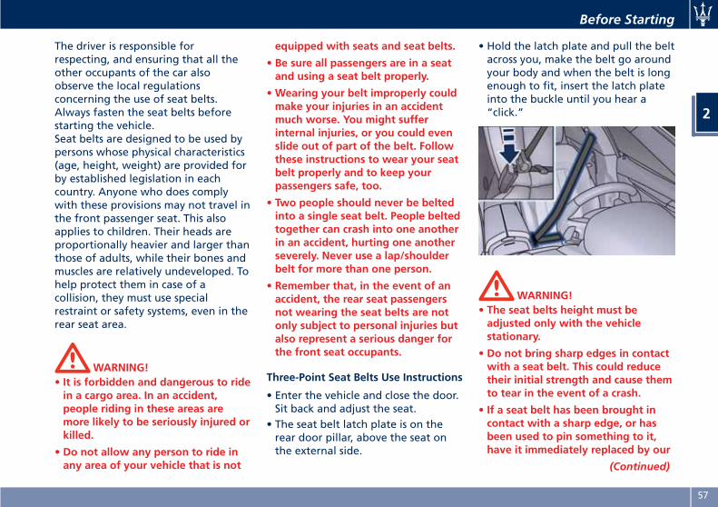
The driver is responsible forrespecting, and ensuring that all theother occupants of the car alsoobserve the local regulationsconcerning the use of seat belts.Always fasten the seat belts beforestarting the vehicle.Seat belts are designed to be used bypersons whose physical characteristics(age, height, weight) are provided forby established legislation in eachcountry. Anyone who does complywith these provisions may not travel inthe front passenger seat. This alsoapplies to children. Their heads areproportionally heavier and larger thanthose of adults, while their bones andmuscles are relatively undeveloped. Tohelp protect them in case of acollision, they must use specialrestraint or safety systems, even in therear seat area.
WARNING!• It is forbidden and dangerous to ridein a cargo area. In an accident,people riding in these areas aremore likely to be seriously injured orkilled.
• Do not allow any person to ride inany area of your vehicle that is not
equipped with seats and seat belts.
• Be sure all passengers are in a seatand using a seat belt properly.
•Wearing your belt improperly couldmake your injuries in an accidentmuch worse. You might sufferinternal injuries, or you could evenslide out of part of the belt. Followthese instructions to wear your seatbelt properly and to keep yourpassengers safe, too.
• Two people should never be beltedinto a single seat belt. People beltedtogether can crash into one anotherin an accident, hurting one anotherseverely. Never use a lap/shoulderbelt for more than one person.
• Remember that, in the event of anaccident, the rear seat passengersnot wearing the seat belts are notonly subject to personal injuries butalso represent a serious danger forthe front seat occupants.
Three-Point Seat Belts Use Instructions
• Enter the vehicle and close the door.Sit back and adjust the seat.
• The seat belt latch plate is on therear door pillar, above the seat onthe external side.
• Hold the latch plate and pull the beltacross you, make the belt go aroundyour body and when the belt is longenough to fit, insert the latch plateinto the buckle until you hear a“click.”
WARNING!• The seat belts height must beadjusted only with the vehiclestationary.
• Do not bring sharp edges in contactwith a seat belt. This could reducetheir initial strength and cause themto tear in the event of a crash.
• If a seat belt has been brought incontact with a sharp edge, or hasbeen used to pin something to it,have it immediately replaced by our
(Continued)
Before Starting
2
57
(Continued)Authorized Maserati Dealer.
• A belt that is latched into the wrongbuckle will not protect you properly.The lap portion of the belt could ridetoo high on your body, possiblycausing internal injuries. Alwayslatch your belt into thecorresponding buckle.
• A belt that is too loose will notprotect you properly. In a suddenstop, you could move too farforward, increasing the possibility ofinjury. Wear your seat beltcomfortably.
• A belt that is worn under your arm isdangerous. Your body could strikethe inside surfaces of the vehicle inan accident, increasing head andneck injury. A belt worn under thearm can also cause internal injuries.
• The lower part must adhere to thepelvis rather than the abdomen ofthe occupant. To fasten the lap beltpull slightly up the diagonal portionof the shoulder belt. To loosen thelap belt if too tight, tilt the latchplate and pull on the lap belt. A snugbelt reduces the risk of sliding underthe belt in an accident.
WARNING!• A lap belt worn too high canincrease the risk of internal injury inan accident. The belt forces won'timpact on the strong hip and pelvicbones, but across your abdomen.Always wear the lap belt as low aspossible and keep it comfortable.
• A twisted belt will not protect youproperly. In a collision, it could evencut into you. Be sure the belt isstraight. If you can't straighten abelt in your vehicle, take it to aService Center immediately.
• Do not use devices (clips, fasteningsetc.) that prevent the seat belts fromlaying close to the occupants bodies.
• Never carry children on a passenger’slap.
• Position the shoulder belt on yourchest so that it is comfortable andnot resting on your neck. Theretractor will withdraw any slack inthe belt.
• To release the belt, push the redbutton on the buckle. The belt willautomatically retract to its stowedposition. If necessary, guide the seatbelt with your hand while it is
rewinding, to prevent it fromtwisting.
WARNING!A frayed or torn belt could break in anaccident and leave you with noprotection. Inspect the belt systemperiodically, checking for cuts, frays, orloose parts. Damaged parts must bereplaced immediately.Do not disassemble or modify thesystem. Seat belt/retractor assembliesmust be replaced by an AuthorizedMaserati Dealer after an accident ifthey have been damaged (bentretractor, torn belt, etc.).
Three-Point Seat Belt HeightAdjustment
WARNING!The seat belts height must only beadjusted when the vehicle isstationary.
The vehicle has a shoulder belt heightadjuster for the driver and frontpassenger seating positions.Adjust the guide so that the shoulderportion of the belt is on the shoulder
Before Starting
2
58
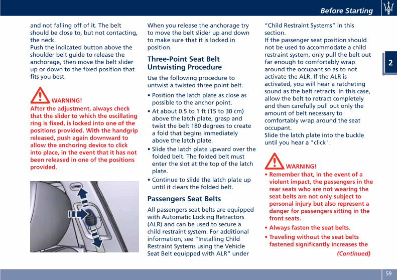
and not falling off of it. The beltshould be close to, but not contacting,the neck.Push the indicated button above theshoulder belt guide to release theanchorage, then move the belt sliderup or down to the fixed position thatfits you best.
WARNING!After the adjustment, always checkthat the slider to which the oscillatingring is fixed, is locked into one of thepositions provided. With the handgripreleased, push again downward toallow the anchoring device to clickinto place, in the event that it has notbeen released in one of the positionsprovided.
When you release the anchorage tryto move the belt slider up and downto make sure that it is locked inposition.
Three-Point Seat BeltUntwisting ProcedureUse the following procedure tountwist a twisted three point belt.
• Position the latch plate as close aspossible to the anchor point.
• At about 0.5 to 1 ft (15 to 30 cm)above the latch plate, grasp andtwist the belt 180 degrees to createa fold that begins immediatelyabove the latch plate.
• Slide the latch plate upward over thefolded belt. The folded belt mustenter the slot at the top of the latchplate.
• Continue to slide the latch plate upuntil it clears the folded belt.
Passengers Seat BeltsAll passengers seat belts are equippedwith Automatic Locking Retractors(ALR) and can be used to secure achild restraint system. For additionalinformation, see “Installing ChildRestraint Systems using the VehicleSeat Belt equipped with ALR” under
“Child Restraint Systems” in thissection.If the passenger seat position shouldnot be used to accommodate a childrestraint system, only pull the belt outfar enough to comfortably wraparound the occupant so as to notactivate the ALR. If the ALR isactivated, you will hear a ratchetingsound as the belt retracts. In this case,allow the belt to retract completelyand then carefully pull out only theamount of belt necessary tocomfortably wrap around the seatoccupant.Slide the latch plate into the buckleuntil you hear a "click".
WARNING!• Remember that, in the event of aviolent impact, the passengers in therear seats who are not wearing theseat belts are not only subject topersonal injury but also represent adanger for passengers sitting in thefront seats.
• Always fasten the seat belts.
• Traveling without the seat beltsfastened significantly increases the
(Continued)
Before Starting
2
59
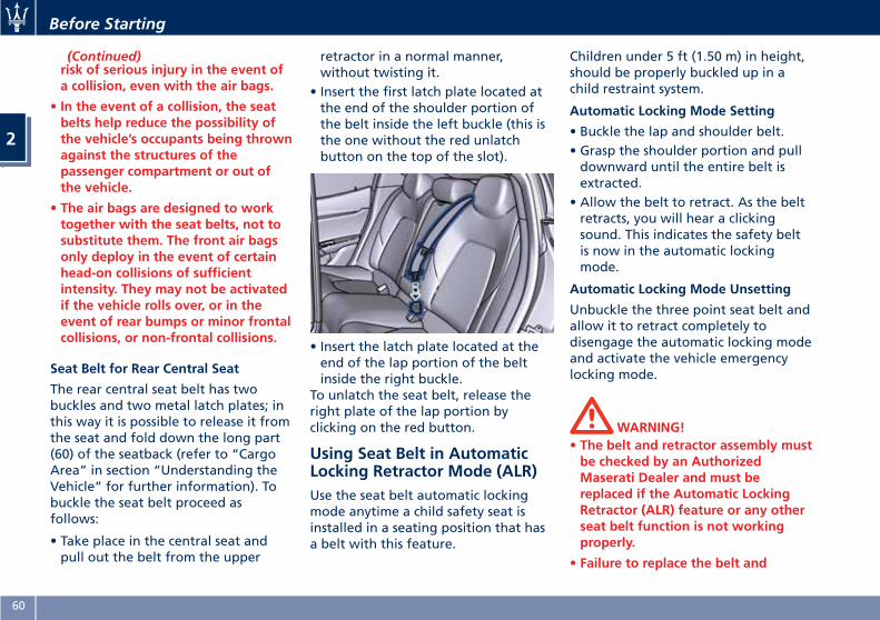
(Continued)risk of serious injury in the event ofa collision, even with the air bags.
• In the event of a collision, the seatbelts help reduce the possibility ofthe vehicle’s occupants being thrownagainst the structures of thepassenger compartment or out ofthe vehicle.
• The air bags are designed to worktogether with the seat belts, not tosubstitute them. The front air bagsonly deploy in the event of certainhead-on collisions of sufficientintensity. They may not be activatedif the vehicle rolls over, or in theevent of rear bumps or minor frontalcollisions, or non-frontal collisions.
Seat Belt for Rear Central Seat
The rear central seat belt has twobuckles and two metal latch plates; inthis way it is possible to release it fromthe seat and fold down the long part(60) of the seatback (refer to “CargoArea” in section “Understanding theVehicle” for further information). Tobuckle the seat belt proceed asfollows:
• Take place in the central seat andpull out the belt from the upper
retractor in a normal manner,without twisting it.
• Insert the first latch plate located atthe end of the shoulder portion ofthe belt inside the left buckle (this isthe one without the red unlatchbutton on the top of the slot).
• Insert the latch plate located at theend of the lap portion of the beltinside the right buckle.
To unlatch the seat belt, release theright plate of the lap portion byclicking on the red button.
Using Seat Belt in AutomaticLocking Retractor Mode (ALR)Use the seat belt automatic lockingmode anytime a child safety seat isinstalled in a seating position that hasa belt with this feature.
Children under 5 ft (1.50 m) in height,should be properly buckled up in achild restraint system.
Automatic Locking Mode Setting
• Buckle the lap and shoulder belt.• Grasp the shoulder portion and pulldownward until the entire belt isextracted.
• Allow the belt to retract. As the beltretracts, you will hear a clickingsound. This indicates the safety beltis now in the automatic lockingmode.
Automatic Locking Mode Unsetting
Unbuckle the three point seat belt andallow it to retract completely todisengage the automatic locking modeand activate the vehicle emergencylocking mode.
WARNING!• The belt and retractor assembly mustbe checked by an AuthorizedMaserati Dealer and must bereplaced if the Automatic LockingRetractor (ALR) feature or any otherseat belt function is not workingproperly.
• Failure to replace the belt and
Before Starting
2
60
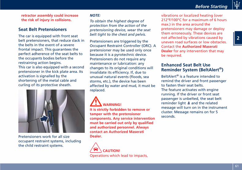
retractor assembly could increasethe risk of injury in collisions.
Seat Belt PretensionersThe car is equipped with front seatbelt pretensioners, that reduce slack inthe belts in the event of a severefrontal impact. This guarantees theperfect adherence of the seat belts tothe occupants bodies before therestraining action begins.This car is also equipped with a secondpretensioner in the kick plate area. Itsactivation is signalled by theshortening of the metal cable andcurling of its protective sheath.
Pretensioners work for all sizeoccupant restraint systems, includingthe child restraint systems.
NOTE:
To obtain the highest degree ofprotection from the action of thepretensioning device, wear the seatbelt tight to the chest and pelvis.
Pretensioners are triggered by theOccupant Restraint Controller (ORC). Apretensioner may be used only oncebecause it is a pyrotechnic device.Pretensioners do not require anymaintenance or lubrication: anychanges to its original conditions willinvalidate its efficiency. If, due tounusual natural events (floods, seastorms, etc.), the device has beenaffected by water and mud, it must bereplaced.
WARNING!It is strictly forbidden to remove ortamper with the pretensionercomponents. Any service interventionmust be carried out only by qualifiedand authorized personnel. Alwayscontact an Authorized MaseratiDealer.
CAUTION!Operations which lead to impacts,
vibrations or localized heating (over212°F/100°C for a maximum of 6 hoursmax.) in the area around thepretensioners may damage or deploythem erroneously. These devices arenot affected by vibrations caused byuneven road surfaces or low obstacles.Contact the Authorized MaseratiDealer for any intervention that maybe required.
Enhanced Seat Belt UseReminder System (BeltAlert®)BeltAlert® is a feature intended toremind the driver and front passengerto fasten their seat belts.The feature activates with enginerunning. If the driver or front seatpassenger is unbelted, the seat beltreminder light and the relatedmessage will turn on in the instrumentcluster. Message remains on for 5seconds.
Before Starting
2
61
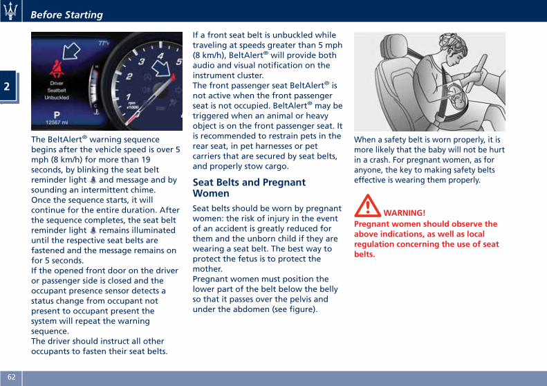
The BeltAlert® warning sequencebegins after the vehicle speed is over 5mph (8 km/h) for more than 19seconds, by blinking the seat beltreminder light and message and bysounding an intermittent chime.Once the sequence starts, it willcontinue for the entire duration. Afterthe sequence completes, the seat beltreminder light remains illuminateduntil the respective seat belts arefastened and the message remains onfor 5 seconds.If the opened front door on the driveror passenger side is closed and theoccupant presence sensor detects astatus change from occupant notpresent to occupant present thesystem will repeat the warningsequence.The driver should instruct all otheroccupants to fasten their seat belts.
If a front seat belt is unbuckled whiletraveling at speeds greater than 5 mph(8 km/h), BeltAlert® will provide bothaudio and visual notification on theinstrument cluster.The front passenger seat BeltAlert® isnot active when the front passengerseat is not occupied. BeltAlert® may betriggered when an animal or heavyobject is on the front passenger seat. Itis recommended to restrain pets in therear seat, in pet harnesses or petcarriers that are secured by seat belts,and properly stow cargo.
Seat Belts and PregnantWomenSeat belts should be worn by pregnantwomen: the risk of injury in the eventof an accident is greatly reduced forthem and the unborn child if they arewearing a seat belt. The best way toprotect the fetus is to protect themother.Pregnant women must position thelower part of the belt below the bellyso that it passes over the pelvis andunder the abdomen (see figure).
When a safety belt is worn properly, it ismore likely that the baby will not be hurtin a crash. For pregnant women, as foranyone, the key to making safety beltseffective is wearing them properly.
WARNING!Pregnant women should observe theabove indications, as well as localregulation concerning the use of seatbelts.
Before Starting
2
62
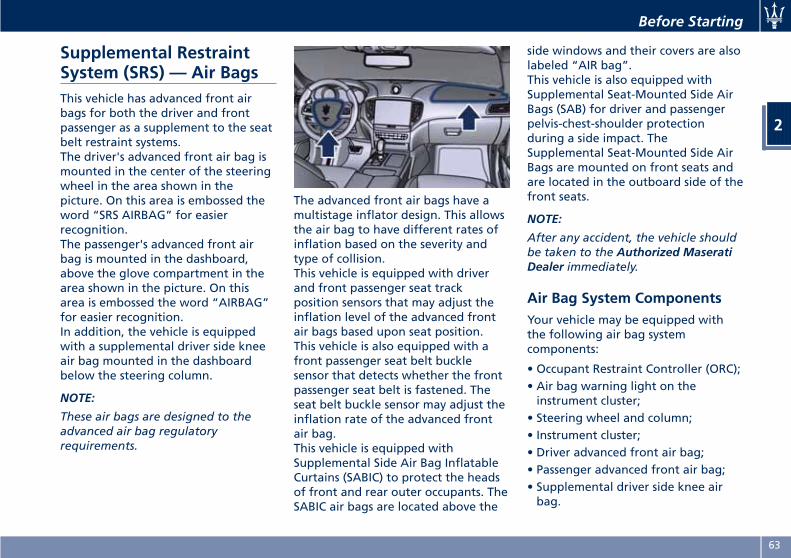
Supplemental RestraintSystem (SRS) — Air BagsThis vehicle has advanced front airbags for both the driver and frontpassenger as a supplement to the seatbelt restraint systems.The driver's advanced front air bag ismounted in the center of the steeringwheel in the area shown in thepicture. On this area is embossed theword “SRS AIRBAG” for easierrecognition.The passenger's advanced front airbag is mounted in the dashboard,above the glove compartment in thearea shown in the picture. On thisarea is embossed the word “AIRBAG”for easier recognition.In addition, the vehicle is equippedwith a supplemental driver side kneeair bag mounted in the dashboardbelow the steering column.
NOTE:
These air bags are designed to theadvanced air bag regulatoryrequirements.
The advanced front air bags have amultistage inflator design. This allowsthe air bag to have different rates ofinflation based on the severity andtype of collision.This vehicle is equipped with driverand front passenger seat trackposition sensors that may adjust theinflation level of the advanced frontair bags based upon seat position.This vehicle is also equipped with afront passenger seat belt bucklesensor that detects whether the frontpassenger seat belt is fastened. Theseat belt buckle sensor may adjust theinflation rate of the advanced frontair bag.This vehicle is equipped withSupplemental Side Air Bag InflatableCurtains (SABIC) to protect the headsof front and rear outer occupants. TheSABIC air bags are located above the
side windows and their covers are alsolabeled “AIR bag”.This vehicle is also equipped withSupplemental Seat-Mounted Side AirBags (SAB) for driver and passengerpelvis-chest-shoulder protectionduring a side impact. TheSupplemental Seat-Mounted Side AirBags are mounted on front seats andare located in the outboard side of thefront seats.
NOTE:
After any accident, the vehicle shouldbe taken to the Authorized MaseratiDealer immediately.
Air Bag System ComponentsYour vehicle may be equipped withthe following air bag systemcomponents:
• Occupant Restraint Controller (ORC);• Air bag warning light on theinstrument cluster;
• Steering wheel and column;• Instrument cluster;• Driver advanced front air bag;• Passenger advanced front air bag;• Supplemental driver side knee airbag.
Before Starting
2
63
• Supplemental Seat-Mounted Side AirBags (SAB);
• Supplemental Side Air Bag InflatableCurtains (SABIC);
• Front and side impact sensors;• Front seat belt pretensioners;• Seat belt buckle switch and seat trackposition sensors;
• Pyrotechnical charge to cut powerfrom the battery; it is located on thepositive battery terminal.
WARNING!The air bag is not a substitute for theseat belts. Correct use of the seatbelts, in combination with the air bag,will offer protection for the driver andpassenger in the front seat in theevent of a head-on collision.
Advanced Front Air BagsPropertiesThe advanced front air bag system hasmultistage driver and front passengerair bags. This system provides air baginflation rates which are appropriateto the severity and type of collision asdetermined by the Occupant RestraintController (ORC), which may receive
information from the front impactsensors.The first stage inflator is triggeredimmediately during an impact thatrequires air bag deployment. Thisinflation rate is used in less severecollisions. A higher energy output,inflation rate, is used for more severecollisions.
CAUTION!
• The electronic control unit providesfor the activation of thepretensioners, front air bags or sideair bags (front and rear) based ondifferent criteria, according to thetype of impact. Failure of one ormore systems to activate is notindicative of a system malfunction.
• The front and/or lateral air bags mayinflate if the vehicle suffers a violentimpact involving the underbodyarea, for example in case of violentimpacts against steps, sidewalks,speed bumps, or when the vehiclefalls into potholes, or similar.
WARNING!• Never place objects (e.g. mobilephones, toys, folders, tablets, ecc..)
on the passenger side of thedashboard since they could interferewith correct inflation of thepassenger air bag and also causeserious injury to the occupants.
• Do not place anything on or aroundthe air bag covers or attempt toopen them manually. You maydamage the air bags and you couldbe injured because the air bags mayno longer be functional. Theprotective covers for the air bag aredesigned to open only when the airbags are inflating.
• Always drive with your hands on thesteering wheel rim, so that the airbag can inflate freely if required.During the drive your back must beas upright as comfort allows and beagainst the seat back with the seatbelt properly fastened.
• Do not apply stickers or otherobjects on the steering wheel, onthe dashboard in the passenger’sside air bag area, on roof side trimsor on the seats.
• Do not travel with objects in your lap,in front of your chest or especially witha pipe, pencil or other objects in yourmouth. In the event of a collision, theintervention of the air bag could resultin serious injury.
Before Starting
2
64
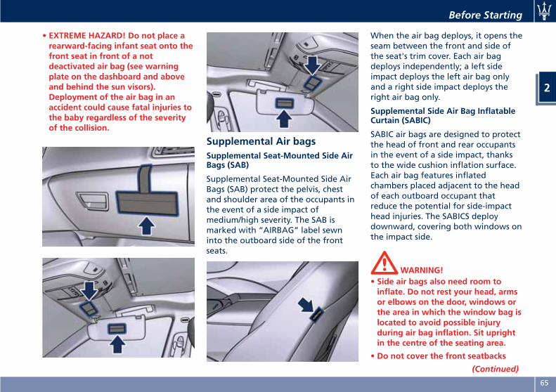
• EXTREME HAZARD! Do not place arearward-facing infant seat onto thefront seat in front of a notdeactivated air bag (see warningplate on the dashboard and aboveand behind the sun visors).Deployment of the air bag in anaccident could cause fatal injuries tothe baby regardless of the severityof the collision.
Supplemental Air bagsSupplemental Seat-Mounted Side AirBags (SAB)
Supplemental Seat-Mounted Side AirBags (SAB) protect the pelvis, chestand shoulder area of the occupants inthe event of a side impact ofmedium/high severity. The SAB ismarked with “AIRBAG” label sewninto the outboard side of the frontseats.
When the air bag deploys, it opens theseam between the front and side ofthe seat's trim cover. Each air bagdeploys independently; a left sideimpact deploys the left air bag onlyand a right side impact deploys theright air bag only.
Supplemental Side Air Bag InflatableCurtain (SABIC)
SABIC air bags are designed to protectthe head of front and rear occupantsin the event of a side impact, thanksto the wide cushion inflation surface.Each air bag features inflatedchambers placed adjacent to the headof each outboard occupant thatreduce the potential for side-impacthead injuries. The SABICS deploydownward, covering both windows onthe impact side.
WARNING!• Side air bags also need room toinflate. Do not rest your head, armsor elbows on the door, windows orthe area in which the window bag islocated to avoid possible injuryduring air bag inflation. Sit uprightin the centre of the seating area.
• Do not cover the front seatbacks
(Continued)
Before Starting
2
65
(Continued)with clothes or covers. Do not useaccessory seat covers or placeobjects between you and the side airbags; the performance could beadversely affected and/or objectscould cause serious injury.
• Do not add roof racks that requirepermanent attachments (bolts orscrews) for installation on thevehicle roof. Do not drill into theroof of the vehicle for any reason.
Supplemental Driver Side Knee Airbag
The supplemental driver side knee airbag provides enhanced protection andworks together with the driveradvanced front air bag during afrontal impact.
Air Bag Deployment Sensorsand ControlsOccupant Restraint Controller (ORC)
The Occupant Restraint Controller(ORC) determines if deployment of thefront air bags and/or side air bags in afrontal or side collision or rolloverevent is required. Based on the impactsensor's signals, a central electronicORC deploys the advanced front airbags, SABIC and SAB air bags, and
front seat belt pretensioners, asrequired, depending on the severityand type of impact.On top of what previously described,the characteristics of the collisionregistered by the sensors and sent tothe control unit of the ORC can alsocause a sudden cut of the power fromthe battery, “blowing” thepyrotechnical charge located on thepositive battery terminal.
CAUTION!After a collision that has caused theignition of the pyrotechnical charge,this must be replaced at an AuthorizedMaserati Dealer.
Advanced front air bags are designedto provide additional protection bysupplementing the seat belts in certainfrontal collisions depending on theseverity and type of collision.Advanced front air bags are notexpected to reduce the risk of injury inrear, side, or rollover collisions.The advanced front air bags will notdeploy in all frontal collisions,including those that may producesubstantial vehicle damage, forexample, some pole collisions, truckunder rides, and corner impacts. Onthe other hand, depending on the
type and location of impact, advancedfront air bags may deploy in crasheswith little vehicle front-end damagebut that produce a severe initialdeceleration.The side air bags will not deploy in allside collisions. Side air bag deploymentwill depend on the severity and typeof collision. Because air bag sensorsmeasure vehicle deceleration overtime, vehicle speed and damagemerely are not good indicators ofwhether or not an air bag should havedeployed.Seat belts are necessary for yourprotection in all accidents, and also areneeded to help keep you in position,away from an inflating air bag. TheORC monitors the readiness of theelectronic parts of the air bag systemwhenever the ignition switch is in theRUN position. If the ignition switch isin the OFF position, in the ACCposition, or not active, the air bagsystem is not activated and the airbags will not inflate.The ORC contains a backup powersupply system that may deploy the airbags even if the battery has low poweror it becomes disconnected prior todeployment. When starting thevehicle, ORC turns on the air bagwarning light on the instrument
Before Starting
2
66
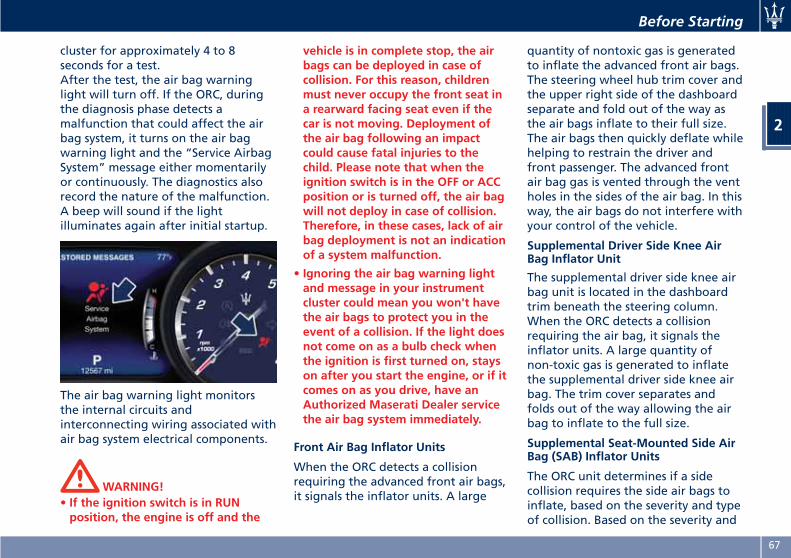
cluster for approximately 4 to 8seconds for a test.After the test, the air bag warninglight will turn off. If the ORC, duringthe diagnosis phase detects amalfunction that could affect the airbag system, it turns on the air bagwarning light and the “Service AirbagSystem” message either momentarilyor continuously. The diagnostics alsorecord the nature of the malfunction.A beep will sound if the lightilluminates again after initial startup.
The air bag warning light monitorsthe internal circuits andinterconnecting wiring associated withair bag system electrical components.
WARNING!• If the ignition switch is in RUNposition, the engine is off and the
vehicle is in complete stop, the airbags can be deployed in case ofcollision. For this reason, childrenmust never occupy the front seat ina rearward facing seat even if thecar is not moving. Deployment ofthe air bag following an impactcould cause fatal injuries to thechild. Please note that when theignition switch is in the OFF or ACCposition or is turned off, the air bagwill not deploy in case of collision.Therefore, in these cases, lack of airbag deployment is not an indicationof a system malfunction.
• Ignoring the air bag warning lightand message in your instrumentcluster could mean you won't havethe air bags to protect you in theevent of a collision. If the light doesnot come on as a bulb check whenthe ignition is first turned on, stayson after you start the engine, or if itcomes on as you drive, have anAuthorized Maserati Dealer servicethe air bag system immediately.
Front Air Bag Inflator Units
When the ORC detects a collisionrequiring the advanced front air bags,it signals the inflator units. A large
quantity of nontoxic gas is generatedto inflate the advanced front air bags.The steering wheel hub trim cover andthe upper right side of the dashboardseparate and fold out of the way asthe air bags inflate to their full size.The air bags then quickly deflate whilehelping to restrain the driver andfront passenger. The advanced frontair bag gas is vented through the ventholes in the sides of the air bag. In thisway, the air bags do not interfere withyour control of the vehicle.
Supplemental Driver Side Knee AirBag Inflator Unit
The supplemental driver side knee airbag unit is located in the dashboardtrim beneath the steering column.When the ORC detects a collisionrequiring the air bag, it signals theinflator units. A large quantity ofnon-toxic gas is generated to inflatethe supplemental driver side knee airbag. The trim cover separates andfolds out of the way allowing the airbag to inflate to the full size.
Supplemental Seat-Mounted Side AirBag (SAB) Inflator Units
The ORC unit determines if a sidecollision requires the side air bags toinflate, based on the severity and typeof collision. Based on the severity and
Before Starting
2
67
type of collision, the side air baginflator on the crash side of the vehiclemay be triggered, releasing a quantityof nontoxic gas.The inflating SAB exits through theseat seam into the space between theoccupant and the door. The side airbag moves at a very high speed andwith such a high force that it couldinjure you if you are not seatedproperly, or if items are positioned inthe area where the side air baginflates. This especially applies tochildren.
Supplemental Side Air Bag InflatableCurtain (SABIC) Inflator Units
During collisions where the impact isconfined to a particular area of theside of the vehicle, the ORC maydeploy the SABIC air bags, dependingon the severity and type of collision. Inthese events, the ORC will deploy theSABIC only on the impact side of thevehicle. A quantity of non-toxic gas isgenerated to inflate the side curtainair bag.The inflating side curtain air bagpushes the head/s of the occupant/sseating in the outside seats from theedge of the headliner out of the wayand covers the window. The air baginflates with enough force to possibly
injure you if you are not belted andseated properly, or if items arepositioned in the area where the sidecurtain air bag inflates. This especiallyapplies to children.The SABICs may also help reduce therisk of partial or complete ejection ofvehicle occupants through sidewindows in certain rollover events(because equipped with rolloversensing).
Front and Side Impact Sensors
In front and side impacts, impactsensors can aid the ORC in determiningappropriate response to impact events.
Enhanced Accident Response System
In the event of an impact causing airbag deployment, if the communicationnetwork and the power remains intact,depending on the nature of theaccident, the ORC will determinewhether the enhanced accidentresponse system will have to performthe following functions:
• cut off fuel to the engine;• turn hazard lights and interior lightson as long as the battery has poweror until the ignition switch is turnedoff;
• unlock the doors automatically;
• disconnect the battery with apyrotechnic charge.
Air Bag Deployment Result
The advanced front air bags aredesigned to deflate immediately afterdeployment.If you do have a collision whichdeploys the air bags, any or all of thefollowing may occur:
• The nylon air bag material maysometimes cause abrasions and/orskin reddening to the driver andfront passenger as the air bagsdeploy and unfold.
• As the air bags deflate, you may seesome smoke-like particles. Theparticles are a normal by-product ofthe process that generates thenon-toxic gas used for air baginflation. These airborne particlesmay irritate the skin, eyes, nose, orthroat. If these particles settle onyour clothing, follow the garmentmanufacturer's instructions forcleaning. Do not drive your vehicleafter the air bags have deployed. Ifyou are involved in another collision,the air bags will not be in place toprotect you.
Before Starting
2
68
ENVIRONMENTAL!Air bag inflation releases a smallamount of powder. This powder is notharmful to the environment.
WARNING!California Proposition 65Operating, servicing and maintaininga passenger vehicle or off-road vehiclecan expose you to chemicals includingsuch as, engine exhaust, carbonmonoxide, phthalates and lead, thatwhich are know to the State ofCalifornia to cause cancer and birthdefects or other reproductive harm. Tominimize exposure, avoid breathingexhaust, do not idle the engine exceptas necessary, service your vehicle in awell-ventilated area and wear glovesor wash your hands frequently whenservicing your vehicle. For moreinformation go to:www.P65Warnings.ca.gov/passenger-vehicle
WARNING!• Deployed air bags and seat belt
pretensioners cannot protect you inanother collision. Have the air bags,seat belt pretensioners, and thefront seat belt retractor assembliesreplaced by a Maserati ServiceCenter. Also, have the OccupantRestraint Controller (ORC) systemserviced as well.
• Have the air bag checked, servicedand replaced only by an AuthorizedMaserati Dealer.
Air Bag System Maintenance
WARNING!•Modifications to any part of the airbag system could cause it to fail;thus you could be injured if the airbag system is not there to protectyou. Do not modify the componentsor wiring. Do not modify the frontbumper, vehicle body structure, oradd aftermarket side steps orrunning boards.
• It is dangerous to try to repair anypart of the air bag system withoutthe necessary know-how.
• Do not attempt to modify any partof your air bag system. The air bagmay inflate accidentally or may notfunction properly if modifications
are made. Take your vehicle to anAuthorized Maserati Dealer for anyair bag system service. If your seatincluding your trim cover andcushion needs to be serviced in anyway (including removal orloosening/tightening of seatattachment bolts), take the vehicleto an Authorized Maserati Dealer.
• Only Maserati manufacturerapproved seat accessories may beused. If it is necessary to modify theair bag system for persons withdisabilities, contact an AuthorizedMaserati Dealer.
• If the speedometer, Rev Counter, orany engine related gauges are notworking, the Occupant RestraintController (ORC) may also bedisabled. The air bags may not beready to inflate for your protection.Promptly check the fuse block forblown fuses. To identify the air bagfuse see “Fuse Replacement” insection "Maintenance and Care". Seean Authorized Maserati Dealer if thefuse is efficient.
Before Starting
2
69
Transport of persons withdisabilityIf it is necessary to modify theadvanced air bag system of yourvehicle to accommodate a person withdisabilities, contact an AuthorizedMaserati Dealer.
WARNING!• The advanced air bag system of yourvehicle is not designed to protectadults with disabilities that requiredeactivation of the passenger ordriver air bag.
• If you or another occupant is anadult with a medical condition thatrequires air bag deactivation, pleasecontact an Authorized MaseratiDealer. For further information ondisabled driver or passengers seehttp://www.safercar.gov.
• As long as the air bag is activated,persons with disabilities are advisednot to travel in the front seat inorder to avoid the risk of seriousinjuries or death, even in minorcrashes.
Event Data Recorder (EDR)This vehicle is equipped with an eventdata recorder (EDR). The main purposeof an EDR is to record, in certain crashor near crash-like situations, such as anair bag deployment or hitting a roadobstacle, data that will assist inunderstanding how a vehicle’s systemshave performed.The EDR is designed to record datarelated to vehicle dynamics and safetysystems for a short period of time,typically 30 seconds or less.The EDR in this vehicle is designed torecord such data as:
• how various systems in your vehiclewere operating;
• whether or not the driver andpassenger safety belts werebuckled/fastened;
• how far (if at all) the driver wasdepressing the accelerator and/orbrake pedal; and
• how fast the vehicle was traveling.These data can help provide a betterunderstanding of the circumstances inwhich crashes and injuries occur.
NOTE:
EDR data are recorded by your vehicleonly if a non-trivial crash situationoccurs; no data are recorded by theEDR under normal driving conditionsand no personal data (e.g., name,gender, age, and crash location) arerecorded. However, other parties, suchas law enforcement, could combinethe EDR data with the type ofpersonally identifying data routinelyacquired during a crash investigation.
To read data recorded by an EDR,special equipment is required, andaccess to the vehicle or the EDR isneeded.In addition to the vehiclemanufacturer, other parties, such aslaw enforcement, that have the specialequipment, can read the informationif they have access to vehicle or theEDR.
Before Starting
2
70
Child Restraint Systems
NOTE:
A child restraint system can helpprotect a child in a vehicle so ensurethat the child restraint selected has acertification label applicable to FMVSS213 in the U.S., or CMVSS 213 inCanada.
Everyone in your vehicle must bebuckled up all the time, includingbabies and children. Every state in theUnited States and all Canadianprovinces require that small childrenride in proper restraint systems. Pleasebe reminded that you can beprosecuted for ignoring this law.Children 12 years or younger shouldride properly buckled up in a rear seat,if available. According to crashstatistics, children are safer whenproperly restrained in the rear seatsrather than in the front.
WARNING!In a collision, an unrestrained child,even a baby, can become a projectileinside the vehicle. The force requiredto hold even an infant on your lapcould become so great that you could
not hold the child, no matter howstrong you are. The child and otherscould be badly injured. Any childriding in your vehicle should alwaysbe in a proper restraint systemsuitable for the child’s size.
There are different sizes and types ofrestraint systems for children fromnewborn size to the child almost largeenough for an adult safety belt.Always refer to the manual providedwith child seat to ensure it is theproper type according the travellingchild. Use the restraint system that iscorrect for your child.
Infants and Child RestraintsSafety experts recommend thatchildren ride rearwardfacing in thevehicle until they are two years old oruntil they reach either the height orweight limit of their rear facing childseat.Two types of child restraint systemscan be used rearward-facing: infantcarriers and convertible child seats.The infant carrier is only usedrearward-facing in the vehicle. It isrecommended for children from birthuntil they reach the weight or heightlimit of the infant carrier.
Convertible child seats can be usedeither rearward-facing orforward-facing in the vehicle.Convertible child seats often have ahigher weight limit in therearward-facing direction than infantcarriers do, so they can be usedrearward-facing by children who haveoutgrown their infant carrier but arestill younger than at least two yearsold.Children should remain rearward-facing until they reach the highestweight or height allowed by theirchild seat. Both types of child restraintsystems are fixed to the car by thelap/shoulder belt or the LATCH childrestraint anchor system. Refer to“Lower Anchors and Tether forCHildren (LATCH)” in this section.
WARNING!• Never place a rear facing infant seatin front of an air bag. A deployingPassenger Advanced Front Air Bagcan cause death or serious injury toa child 12 years or younger,including a child in a rearwardfacing infant seat.
(Continued)
Before Starting
2
71
(Continued)• Only use a rearward-facing childrestraint in a vehicle with a rear seat.
Older Children and ChildRestraintsChildren who are two years old or whohave outgrown their rear-facing childseat can ride forward-facing in thevehicle. Forward-facing child seats andconvertible child seats used in theforward-facing direction are forchildren who are over two years old orwho have outgrown the rear-facingweight or height limit of theirrear-facing child seat.Children should remain in aforward-facing child seat with aharness for as long as possible, up tothe highest weight or height allowedby the child seat. These child seats arealso fixed to the car by thelap/shoulder belt or the LATCH childrestraint anchorage system. Refer to“Lower Anchors and Tether forCHildren (LATCH)” in this section.All children whose weight or height isabove the forward-facing limit for thechild seat should use a belt-positioningbooster seat until the vehicle’s seatbelts fit properly. If the child cannot sitwith knees bent over the vehicle’s seat
cushion while the back is against theseatback, they should use abelt-positioning booster seat.The child and belt-positioning boosterseat are fixed to the car by thelap/shoulder belt.
Children Too Large for BoosterSeatsChildren who are large enough towear the shoulder belt comfortablyand whose legs are long enough tobend over the front of the seat whentheir back is against the seatbackshould use the lap/shoulder belt in arear seat.
• Make sure that the child is upright inthe seat.
• The lap portion should be low on thehips and as snug as possible.
• Check belt fit periodically. A child’ssquirming or slouching can move thebelt out of position.
• If the shoulder belt contacts the faceor neck, move the child closer to thecenter of the vehicle. Never allow achild to put the shoulder belt underan arm or behind their back.
NOTE:
For additional information, refer towww.seatcheck.org or call1–866–SEATCHECK. Canadian residentsshould refer to Transport Canada’swebsite for additional information:http://www.tc.gc.ca/roadsafety/safedrivers/childsafety/index.htm
WARNING!• Improper installation can lead tofailure of an infant or child restraint.It could come loose in a collision. Thechild could be badly injured or killed.Follow the restraint manufacturer’sdirections exactly when installing aninfant or child restraint.
• A rearward-facing child restraintshould only be used in a rear seat. Arearward-facing child restraint in thefront seat may be struck by adeploying passenger air bag, whichmay cause severe or fatal injury tothe infant.
Here are some tips on gettingthe most out of your childrestraint• Before buying any restraint system,make sure that it has a label
Before Starting
2
72
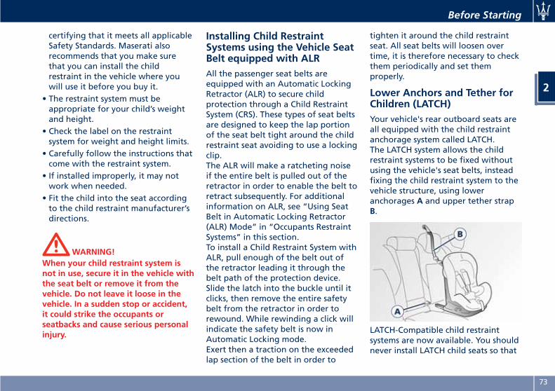
certifying that it meets all applicableSafety Standards. Maserati alsorecommends that you make surethat you can install the childrestraint in the vehicle where youwill use it before you buy it.
• The restraint system must beappropriate for your child’s weightand height.
• Check the label on the restraintsystem for weight and height limits.
• Carefully follow the instructions thatcome with the restraint system.
• If installed improperly, it may notwork when needed.
• Fit the child into the seat accordingto the child restraint manufacturer’sdirections.
WARNING!When your child restraint system isnot in use, secure it in the vehicle withthe seat belt or remove it from thevehicle. Do not leave it loose in thevehicle. In a sudden stop or accident,it could strike the occupants orseatbacks and cause serious personalinjury.
Installing Child RestraintSystems using the Vehicle SeatBelt equipped with ALRAll the passenger seat belts areequipped with an Automatic LockingRetractor (ALR) to secure childprotection through a Child RestraintSystem (CRS). These types of seat beltsare designed to keep the lap portionof the seat belt tight around the childrestraint seat avoiding to use a lockingclip.The ALR will make a ratcheting noiseif the entire belt is pulled out of theretractor in order to enable the belt toretract subsequently. For additionalinformation on ALR, see “Using SeatBelt in Automatic Locking Retractor(ALR) Mode” in “Occupants RestraintSystems” in this section.To install a Child Restraint System withALR, pull enough of the belt out ofthe retractor leading it through thebelt path of the protection device.Slide the latch into the buckle until itclicks, then remove the entire safetybelt from the retractor in order torewound. While rewinding a click willindicate the safety belt is now inAutomatic Locking mode.Exert then a traction on the exceededlap section of the belt in order to
tighten it around the child restraintseat. All seat belts will loosen overtime, it is therefore necessary to checkthem periodically and set themproperly.
Lower Anchors and Tether forChildren (LATCH)Your vehicle's rear outboard seats areall equipped with the child restraintanchorage system called LATCH.The LATCH system allows the childrestraint systems to be fixed withoutusing the vehicle's seat belts, insteadfixing the child restraint system to thevehicle structure, using loweranchorages A and upper tether strapB.
LATCH-Compatible child restraintsystems are now available. You shouldnever install LATCH child seats so that
Before Starting
2
73

two seats share a common loweranchorage.If your child restraints are notLATCH-Compatible, install therestraints using the vehicle's seat belts.
Installing a LATCH- Compatible ChildRestraint System
The lower LATCH anchorages are“U-shaped” metal rings located on therear seat where the cushion meets theseatback just below the symbol shownin the picture, but are not visible. Youwill find them if you run your fingeralong the intersection of the seatbackand seat cushion surfaces.
In addition, there are tether strapanchorages behind each rear seat.
NOTE:
The top tether strap anchorage behindthe central rear seat should be used tosecure a child restraint system with thevehicle's seat belts.
To install a LATCH-Compatible childrestraint seat proceed as follows.
• Secure the child seat to the“U-shaped” lower metal ringspositioned on the rear seat.
• Fix the top tether strap (providedwith the child seat), to the anchorlocated in the panel between therear seat back and the rear window.
• Lift the plastic cover located behindthe seat where you want to installthe child restraint system.
• Route the top tether strap to providethe most direct path between theanchorage and the child restraintsystem passing it over the headrest.
• Attach the hook of the top tetherstrap (provided with the childrestraint system) to the anchor.
• Tighten the upper strap until youreach the tension levelrecommended by the restraintsystem manufacturer.
Before Starting
2
74
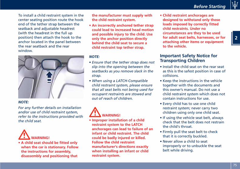
To install a child restraint system in thecenter seating position route the hookend of the tether strap between theseatback and adjustable headrest(with the headrest in the full upposition) then attach the hook to theanchor located in the panel betweenthe rear seatback and the rearwindow.
NOTE:
For any further details on installationand/or use of child restraint system,refer to the instructions provided withthe child seat.
WARNING!• A child seat should be fitted onlywhen the car is stationary. Followthe instructions for assembly,disassembly and positioning that
the manufacturer must supply withthe child restraint system.
• An incorrectly anchored tether strapcould lead to increased head motionand possible injury to the child. Useonly the anchor position directlybehind the child seat to secure achild restraint top tether strap.
NOTE:
• Ensure that the tether strap does notslip into the opening between theseatbacks as you remove slack in thestrap.
•When using a LATCH-Compatiblechild restraint system, please ensurethat all seat belts not being used foroccupant restraints are stowed andout of reach of children.
WARNING!• Improper installation of a childrestraint system to the LATCHanchorages can lead to failure of aninfant or child restraint. The childcould be badly injured or killed.Follow the child restraintmanufacturer's directions exactlywhen installing an infant or childrestraint system.
• Child restraint anchorages aredesigned to withstand only thoseloads imposed by correctly fittedchild restraints. Under nocircumstances are they to be usedfor adult seat belts, harnesses, or forattaching other items or equipmentto the vehicle.
Important Safety Notice forTransporting Children• Install the child seat on the rear seatas this is the safest position in case ofcollisions.
• Keep the instructions in the vehicletogether with the documents andthis owner’s manual. Do not use achild restraint system which does notcontain instructions for use.
• Every child has to use one childrestraint system; never carry twochildren using only one child seat.
• If using the vehicle seat belt, alwayscheck that the belt does not restrainthe child's throat.
• Firmly pull the seat belt to checkthat it is correctly buckled.
• Never allow a child to seatimproperly or to unbuckle the seatbelt while driving.
Before Starting
2
75
• Never allow a child to wear theshoulder portion of the belt underthe arms or behind the back.
• Never carry children on your lap, noteven newborns. No one can restraina child in the event of an accident.
• In case of accident, replace the childseat with a new one.
Transporting PetsAir bags deploying in the front seatcould harm your pet. An unrestrainedpet will be thrown about and possiblyinjured, or injure a passenger duringpanic braking or in an accident.Pets should be restrained in the rearseat in pet harnesses or pet carriersthat are secured by vehicle seat belts.
Rear Parking CameraYour vehicle is equipped with a rearparking camera that allows you to seean image on the MTC+ screen of therear surroundings of your vehiclewhenever the shift lever is put into R(Reverse).When “Parkview Backup CameraDelay” mode is enabled, the rear viewimage shall be displayed for up to 10seconds after shifting out of R(Reverse).When “Rearwiew Camera Delay”mode is enabled, the rear view imageshall be displayed for up to 10 secondsafter shifting out of R (Reverse).To assist the driver during maneuverson dead-ends/roads and onintersections, the vehicle may beequipped with an optional surroundview camera system. For more detailson this option, see chapter "SurroundView Camera System (optional)" in thissection.The image will be displayed along witha caution note to “Check EntireSurroundings” across the top of thescreen. After five seconds this note willdisappear.The rear parking camera is located onthe rear of the vehicle above the rearlicense plate.
Before Starting
2
76
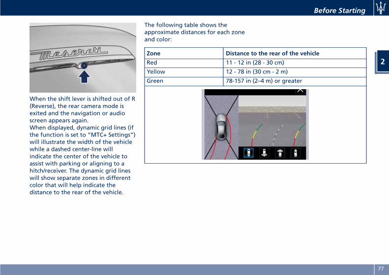
When the shift lever is shifted out of R(Reverse), the rear camera mode isexited and the navigation or audioscreen appears again.When displayed, dynamic grid lines (ifthe function is set to “MTC+ Settings”)will illustrate the width of the vehiclewhile a dashed center-line willindicate the center of the vehicle toassist with parking or aligning to ahitch/receiver. The dynamic grid lineswill show separate zones in differentcolor that will help indicate thedistance to the rear of the vehicle.
The following table shows theapproximate distances for each zoneand color:
Zone Distance to the rear of the vehicle
Red 11 - 12 in (28 - 30 cm)
Yellow 12 - 78 in (30 cm - 2 m)
Green 78-157 in (2–4 m) or greater
Before Starting
2
77
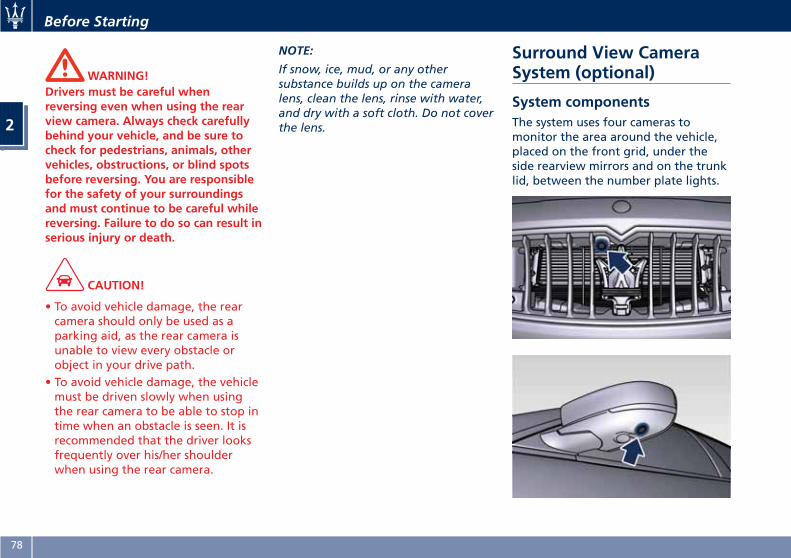
WARNING!Drivers must be careful whenreversing even when using the rearview camera. Always check carefullybehind your vehicle, and be sure tocheck for pedestrians, animals, othervehicles, obstructions, or blind spotsbefore reversing. You are responsiblefor the safety of your surroundingsand must continue to be careful whilereversing. Failure to do so can result inserious injury or death.
CAUTION!
• To avoid vehicle damage, the rearcamera should only be used as aparking aid, as the rear camera isunable to view every obstacle orobject in your drive path.
• To avoid vehicle damage, the vehiclemust be driven slowly when usingthe rear camera to be able to stop intime when an obstacle is seen. It isrecommended that the driver looksfrequently over his/her shoulderwhen using the rear camera.
NOTE:
If snow, ice, mud, or any othersubstance builds up on the cameralens, clean the lens, rinse with water,and dry with a soft cloth. Do not coverthe lens.
Surround View CameraSystem (optional)
System componentsThe system uses four cameras tomonitor the area around the vehicle,placed on the front grid, under theside rearview mirrors and on the trunklid, between the number plate lights.
Before Starting
2
78
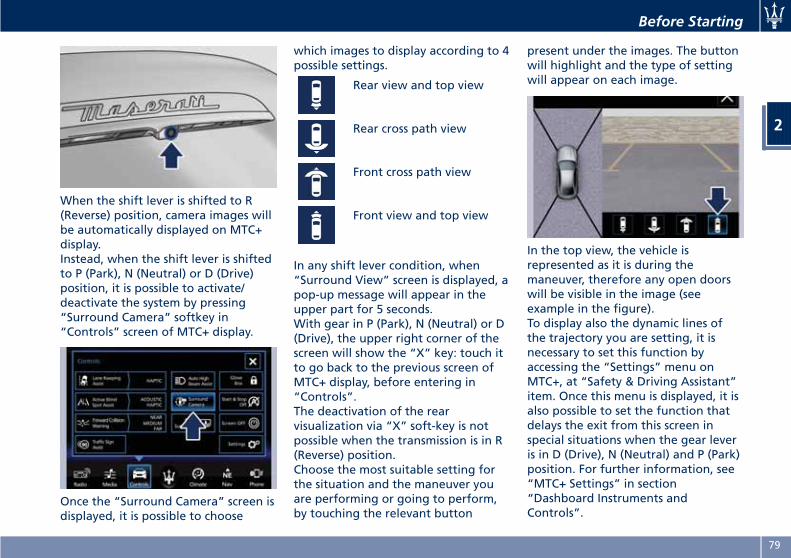
When the shift lever is shifted to R(Reverse) position, camera images willbe automatically displayed on MTC+display.Instead, when the shift lever is shiftedto P (Park), N (Neutral) or D (Drive)position, it is possible to activate/deactivate the system by pressing“Surround Camera” softkey in“Controls” screen of MTC+ display.
Once the “Surround Camera” screen isdisplayed, it is possible to choose
which images to display according to 4possible settings.
Rear view and top view
Rear cross path view
Front cross path view
Front view and top view
In any shift lever condition, when“Surround View” screen is displayed, apop-up message will appear in theupper part for 5 seconds.With gear in P (Park), N (Neutral) or D(Drive), the upper right corner of thescreen will show the “X” key: touch itto go back to the previous screen ofMTC+ display, before entering in“Controls”.The deactivation of the rearvisualization via “X” soft-key is notpossible when the transmission is in R(Reverse) position.Choose the most suitable setting forthe situation and the maneuver youare performing or going to perform,by touching the relevant button
present under the images. The buttonwill highlight and the type of settingwill appear on each image.
In the top view, the vehicle isrepresented as it is during themaneuver, therefore any open doorswill be visible in the image (seeexample in the figure).To display also the dynamic lines ofthe trajectory you are setting, it isnecessary to set this function byaccessing the “Settings” menu onMTC+, at “Safety & Driving Assistant”item. Once this menu is displayed, it isalso possible to set the function thatdelays the exit from this screen inspecial situations when the gear leveris in D (Drive), N (Neutral) and P (Park)position. For further information, see“MTC+ Settings” in section“Dashboard Instruments andControls”.
Before Starting
2
79
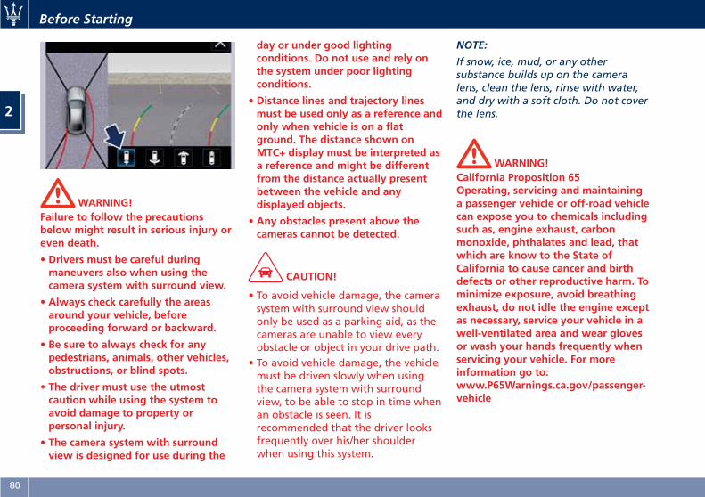
WARNING!Failure to follow the precautionsbelow might result in serious injury oreven death.
• Drivers must be careful duringmaneuvers also when using thecamera system with surround view.
• Always check carefully the areasaround your vehicle, beforeproceeding forward or backward.
• Be sure to always check for anypedestrians, animals, other vehicles,obstructions, or blind spots.
• The driver must use the utmostcaution while using the system toavoid damage to property orpersonal injury.
• The camera system with surroundview is designed for use during the
day or under good lightingconditions. Do not use and rely onthe system under poor lightingconditions.
• Distance lines and trajectory linesmust be used only as a reference andonly when vehicle is on a flatground. The distance shown onMTC+ display must be interpreted asa reference and might be differentfrom the distance actually presentbetween the vehicle and anydisplayed objects.
• Any obstacles present above thecameras cannot be detected.
CAUTION!
• To avoid vehicle damage, the camerasystem with surround view shouldonly be used as a parking aid, as thecameras are unable to view everyobstacle or object in your drive path.
• To avoid vehicle damage, the vehiclemust be driven slowly when usingthe camera system with surroundview, to be able to stop in time whenan obstacle is seen. It isrecommended that the driver looksfrequently over his/her shoulderwhen using this system.
NOTE:
If snow, ice, mud, or any othersubstance builds up on the cameralens, clean the lens, rinse with water,and dry with a soft cloth. Do not coverthe lens.
WARNING!California Proposition 65Operating, servicing and maintaininga passenger vehicle or off-road vehiclecan expose you to chemicals includingsuch as, engine exhaust, carbonmonoxide, phthalates and lead, thatwhich are know to the State ofCalifornia to cause cancer and birthdefects or other reproductive harm. Tominimize exposure, avoid breathingexhaust, do not idle the engine exceptas necessary, service your vehicle in awell-ventilated area and wear glovesor wash your hands frequently whenservicing your vehicle. For moreinformation go to:www.P65Warnings.ca.gov/passenger-vehicle
Before Starting
2
80
Safety Tips
Transporting Passengers
WARNING!• Do not leave children or animalsinside parked vehicles in hotweather. Interior heat build-up maycause serious injury.
• Never ride in a cargo area, inside ofa vehicle.
• Do not allow people to ride in anyarea of your vehicle that is notequipped with seats and seat belts.
• Be sure everyone in your vehicle isin a seat and using a seat beltproperly.
Exhaust Gas
WARNING!Exhaust gases can injure. They containcarbon monoxide (CO), which iscolorless and odorless. Breathing itcan make you unconscious and caneventually poison you. To avoidbreathing (CO), follow these safetytips:
• Do not run the engine in a closedgarage or in confined areas anylonger than needed to move yourvehicle in or out of the area.
• If it is necessary to sit in a parkedvehicle with the engine running,adjust your heating or coolingcontrols to force outside air into thevehicle. Set the blower at highspeed.
• If you are required to drive with thetrunk open, make sure that allwindows are closed and the climatecontrol blowers switch is set at highspeed. DO NOT use the recirculationmode.
The best protection against carbonmonoxide entry into the passengercompartment is a properly maintainedengine exhaust system.Whenever detecting a change in thesound of the exhaust system oreventual exhaust fumes inside thevehicle have the Authorized MaseratiDealer inspect the complete exhaustsystem and adjacent body areas forbroken, damaged, deteriorated, ormispositioned parts.Open seams or loose connectionscould permit exhaust fumes to seepinto the passenger compartment.
WARNING!California Proposition 65Operating, servicing and maintaininga passenger vehicle or off-road vehiclecan expose you to chemicals includingsuch as, engine exhaust, carbonmonoxide, phthalates and lead, thatwhich are know to the State ofCalifornia to cause cancer and birthdefects or other reproductive harm. Tominimize exposure, avoid breathingexhaust, do not idle the engine exceptas necessary, service your vehicle in awell-ventilated area and wear glovesor wash your hands frequently whenservicing your vehicle. For moreinformation go to:www.P65Warnings.ca.gov/passenger-vehicle
Vehicle Safety ChecksSeat Belts
• Inspect the belt system periodically,checking for cuts, frays, and looseparts. Damaged parts must bereplaced immediately.
• Do not disassemble or modify thesystem.
• If the belt has been sharply pulled,for example as the result of an
Before Starting
2
81
accident, the safety belt, togetherwith the anchoring devices, theanchoring device mounting screwsand the pretensioner must becompletely replaced. Even if the beltdoes not present any exterior signsof wear or damage, it may have lostits restraining properties.
Air Bag Warning Light
The light should illuminate andremain lit for a few seconds bulbchecking when the ignition switch ispushed in RUN position (see“Supplemental Restraint System (SRS)— Air Bags” chapter in this section).
• If the light does not illuminatewhile starting, contact theAuthorized Maserati Dealer.
• If the light stays on, flickers, or comeson while driving, have the systemchecked by the Authorized MaseratiDealer.
WARNING!Certain components of this vehiclesuch as air bag modules, seat beltpretensioners, adaptive steeringcolumns, and button cell batteries maycontain Perchlorate material. Specialhandling may apply for service or
vehicle end of life disposal. Seewww.dtsc.ca.gov/hazardouswaste/perchlorate.
Defroster
Check operation by selecting thedefrost mode and place the fan systemon high speed (see “Air ConditioningControls” chapter in section“Dashboard Instruments andControls”).You should be able to feel the airdirected against the windshield andfront side windows. ContactAuthorized Maserati Dealer for serviceif your defroster is inoperable.
Floor Mat
Always use floor mats designed to fitthe footwell of your vehicle. Use onlyfloor mats that leave the pedal areaunobstructed and that are firmlysecured so that they cannot slip out ofposition and interfere with the pedalsor impair safe operation of yourvehicle.
NOTE:
The Authorized Maserati Dealer canprovide you with any informationabout the available Maserati floormats included in the “GenuineAccessories” range.
WARNING!Pedals that cannot move freely cancause loss of vehicle control andincrease the risk of serious personalinjury.
• Always make sure that floor matsare properly attached to the properfasteners.
• Never place or install floor mats orother floor coverings in the vehiclethat cannot be properly secured toprevent them from moving andinterfering with the pedals.
• Never put floor mats or other floorcoverings on top of already installedfloor mats. Additional floor mats andother coverings will reduce the sizeof the pedal area and interfere withthe pedals.
• Check mounting of mats on a regularbasis. Always properly reinstall andsecure floor mats that have been
Before Starting
2
82
removed for cleaning.
• Always make sure that objectscannot fall into the driver footwellwhile the vehicle is moving. Objectscan become trapped under thebrake pedal and accelerator pedalcausing a loss of vehicle control.
•Mounting posts must be properlyinstalled, if not equipped from thefactory. Failure to properly followfloor mat installation or mountingcan cause interference with thebrake pedal and accelerator pedaloperation causing loss of control ofthe vehicle.
Tires
• Examine tires for excessive treadwear and uneven wear patterns.
• Check for stones, nails, glass, orother objects lodged in the tread orsidewall.
• Inspect the tread for cuts and cracks.• Inspect sidewalls for cuts, cracks andbulges.
• Check the wheel nuts for tightness.• Check the tires (see “Tire InflationPressure” chapter in section“Features and Specifications”) forproper cold inflation pressure.
Lights and Indicator Lights
• Have someone observe theoperation of exterior lights whileyou operate the controls (see“Lights” chapter in section“Understanding the Vehicle”).
• Check turn signal and high beamindicator lights on the instrumentcluster (see “Instrument Cluster”chapter in section “DashboardInstruments and Controls”).
Door Latches
• Check for positive closing, latching,and locking of doors and trunk lid(see “Unlock the Vehicle with Keyfob” chapter in this section).
Fluid Leaks
• Check area under vehicle afterovernight parking for recent fluidleaks (oil, fuel, etc.).
• If gasoline fumes are detected orfluid leaks are suspected, contact theAuthorized Maserati Dealer.
WARNING!California Proposition 65Operating, servicing and maintaininga passenger vehicle or off-road vehiclecan expose you to chemicals includingsuch as, engine exhaust, carbon
monoxide, phthalates and lead, thatwhich are know to the State ofCalifornia to cause cancer and birthdefects or other reproductive harm. Tominimize exposure, avoid breathingexhaust, do not idle the engine exceptas necessary, service your vehicle in awell-ventilated area and wear glovesor wash your hands frequently whenservicing your vehicle. For moreinformation go to:www.P65Warnings.ca.gov/passenger-vehicle
Before Starting
2
83
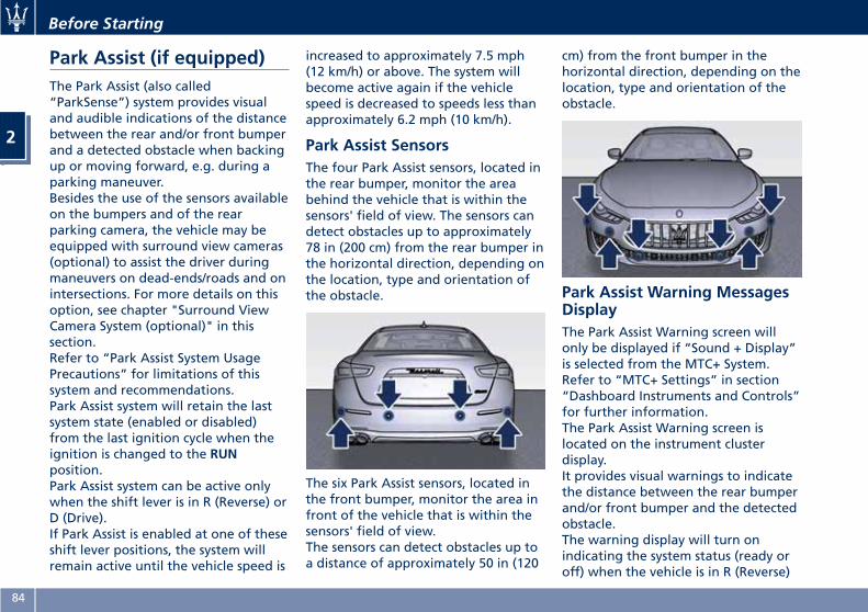
Park Assist (if equipped)The Park Assist (also called“ParkSense”) system provides visualand audible indications of the distancebetween the rear and/or front bumperand a detected obstacle when backingup or moving forward, e.g. during aparking maneuver.Besides the use of the sensors availableon the bumpers and of the rearparking camera, the vehicle may beequipped with surround view cameras(optional) to assist the driver duringmaneuvers on dead-ends/roads and onintersections. For more details on thisoption, see chapter "Surround ViewCamera System (optional)" in thissection.Refer to “Park Assist System UsagePrecautions” for limitations of thissystem and recommendations.Park Assist system will retain the lastsystem state (enabled or disabled)from the last ignition cycle when theignition is changed to the RUNposition.Park Assist system can be active onlywhen the shift lever is in R (Reverse) orD (Drive).If Park Assist is enabled at one of theseshift lever positions, the system willremain active until the vehicle speed is
increased to approximately 7.5 mph(12 km/h) or above. The system willbecome active again if the vehiclespeed is decreased to speeds less thanapproximately 6.2 mph (10 km/h).
Park Assist SensorsThe four Park Assist sensors, located inthe rear bumper, monitor the areabehind the vehicle that is within thesensors' field of view. The sensors candetect obstacles up to approximately78 in (200 cm) from the rear bumper inthe horizontal direction, depending onthe location, type and orientation ofthe obstacle.
The six Park Assist sensors, located inthe front bumper, monitor the area infront of the vehicle that is within thesensors' field of view.The sensors can detect obstacles up toa distance of approximately 50 in (120
cm) from the front bumper in thehorizontal direction, depending on thelocation, type and orientation of theobstacle.
Park Assist Warning MessagesDisplayThe Park Assist Warning screen willonly be displayed if “Sound + Display”is selected from the MTC+ System.Refer to “MTC+ Settings” in section“Dashboard Instruments and Controls”for further information.The Park Assist Warning screen islocated on the instrument clusterdisplay.It provides visual warnings to indicatethe distance between the rear bumperand/or front bumper and the detectedobstacle.The warning display will turn onindicating the system status (ready oroff) when the vehicle is in R (Reverse)
Before Starting
2
84
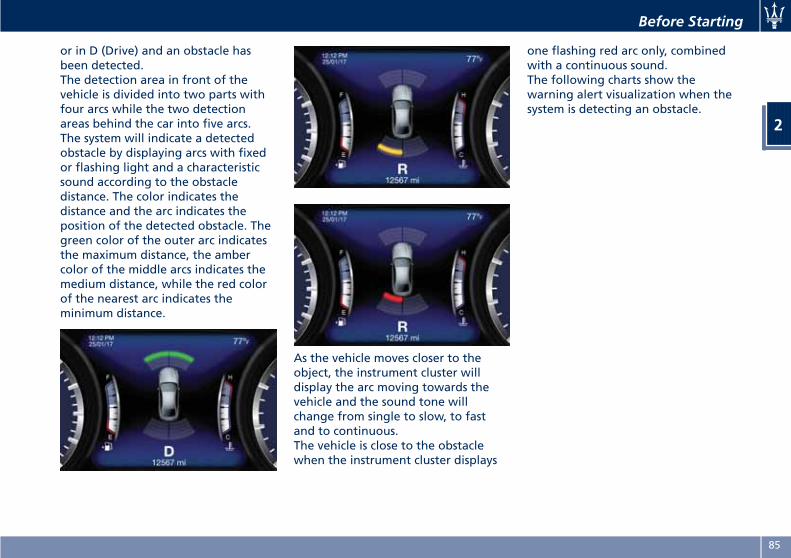
or in D (Drive) and an obstacle hasbeen detected.The detection area in front of thevehicle is divided into two parts withfour arcs while the two detectionareas behind the car into five arcs.The system will indicate a detectedobstacle by displaying arcs with fixedor flashing light and a characteristicsound according to the obstacledistance. The color indicates thedistance and the arc indicates theposition of the detected obstacle. Thegreen color of the outer arc indicatesthe maximum distance, the ambercolor of the middle arcs indicates themedium distance, while the red colorof the nearest arc indicates theminimum distance.
As the vehicle moves closer to theobject, the instrument cluster willdisplay the arc moving towards thevehicle and the sound tone willchange from single to slow, to fastand to continuous.The vehicle is close to the obstaclewhen the instrument cluster displays
one flashing red arc only, combinedwith a continuous sound.The following charts show thewarning alert visualization when thesystem is detecting an obstacle.
Before Starting
2
85
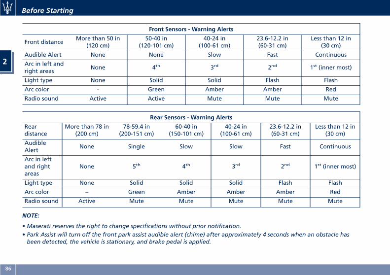
Front Sensors - Warning Alerts
Front distanceMore than 50 in
(120 cm)50-40 in
(120-101 cm)40-24 in
(100-61 cm)23.6-12.2 in(60-31 cm)
Less than 12 in(30 cm)
Audible Alert None None Slow Fast Continuous
Arc in left andright areas
None 4th 3rd 2nd 1st (inner most)
Light type None Solid Solid Flash Flash
Arc color - Green Amber Amber Red
Radio sound Active Active Mute Mute Mute
Rear Sensors - Warning Alerts
Reardistance
More than 78 in(200 cm)
78-59.4 in(200-151 cm)
60-40 in(150-101 cm)
40-24 in(100-61 cm)
23.6-12.2 in(60-31 cm)
Less than 12 in(30 cm)
AudibleAlert
None Single Slow Slow Fast Continuous
Arc in leftand rightareas
None 5th 4th 3rd 2nd 1st (inner most)
Light type None Solid Solid Solid Flash Flash
Arc color – Green Amber Amber Amber Red
Radio sound Active Mute Mute Mute Mute Mute
NOTE:
•Maserati reserves the right to change specifications without prior notification.• Park Assist will turn off the front park assist audible alert (chime) after approximately 4 seconds when an obstacle hasbeen detected, the vehicle is stationary, and brake pedal is applied.
Before Starting
2
86
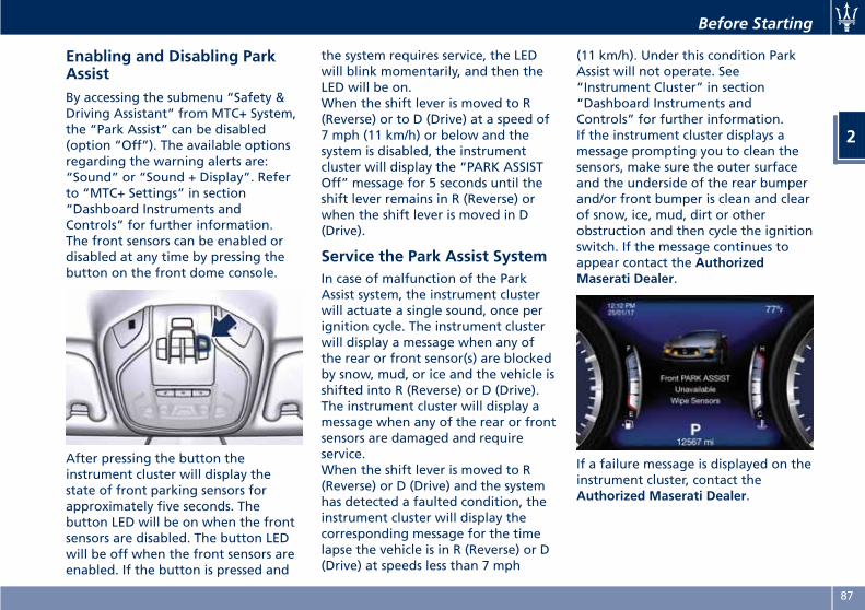
Enabling and Disabling ParkAssistBy accessing the submenu “Safety &Driving Assistant” from MTC+ System,the “Park Assist” can be disabled(option “Off”). The available optionsregarding the warning alerts are:“Sound” or “Sound + Display”. Referto “MTC+ Settings” in section“Dashboard Instruments andControls” for further information.The front sensors can be enabled ordisabled at any time by pressing thebutton on the front dome console.
After pressing the button theinstrument cluster will display thestate of front parking sensors forapproximately five seconds. Thebutton LED will be on when the frontsensors are disabled. The button LEDwill be off when the front sensors areenabled. If the button is pressed and
the system requires service, the LEDwill blink momentarily, and then theLED will be on.When the shift lever is moved to R(Reverse) or to D (Drive) at a speed of7 mph (11 km/h) or below and thesystem is disabled, the instrumentcluster will display the “PARK ASSISTOff” message for 5 seconds until theshift lever remains in R (Reverse) orwhen the shift lever is moved in D(Drive).
Service the Park Assist SystemIn case of malfunction of the ParkAssist system, the instrument clusterwill actuate a single sound, once perignition cycle. The instrument clusterwill display a message when any ofthe rear or front sensor(s) are blockedby snow, mud, or ice and the vehicle isshifted into R (Reverse) or D (Drive).The instrument cluster will display amessage when any of the rear or frontsensors are damaged and requireservice.When the shift lever is moved to R(Reverse) or D (Drive) and the systemhas detected a faulted condition, theinstrument cluster will display thecorresponding message for the timelapse the vehicle is in R (Reverse) or D(Drive) at speeds less than 7 mph
(11 km/h). Under this condition ParkAssist will not operate. See“Instrument Cluster” in section“Dashboard Instruments andControls” for further information.If the instrument cluster displays amessage prompting you to clean thesensors, make sure the outer surfaceand the underside of the rear bumperand/or front bumper is clean and clearof snow, ice, mud, dirt or otherobstruction and then cycle the ignitionswitch. If the message continues toappear contact the AuthorizedMaserati Dealer.
If a failure message is displayed on theinstrument cluster, contact theAuthorized Maserati Dealer.
Before Starting
2
87
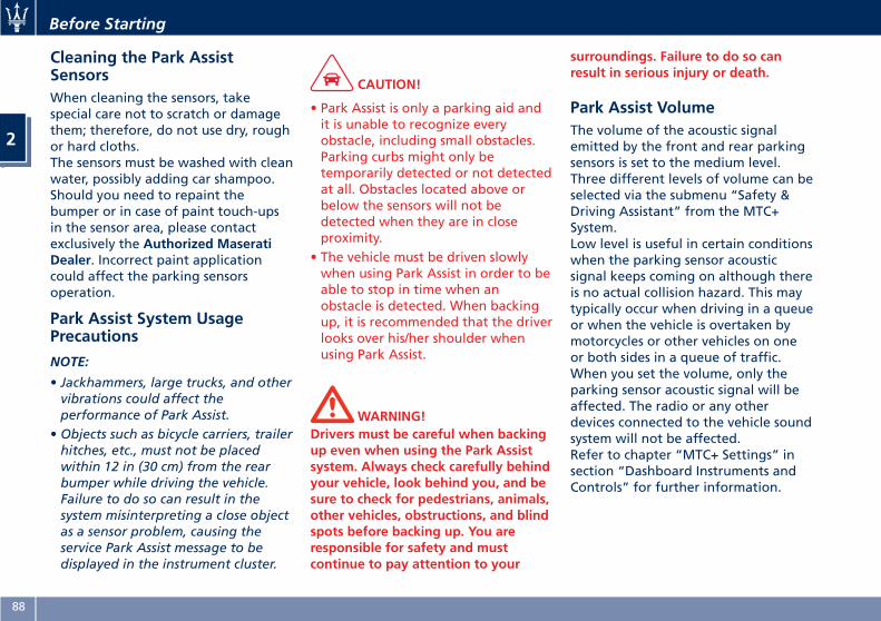
Cleaning the Park AssistSensorsWhen cleaning the sensors, takespecial care not to scratch or damagethem; therefore, do not use dry, roughor hard cloths.The sensors must be washed with cleanwater, possibly adding car shampoo.Should you need to repaint thebumper or in case of paint touch-upsin the sensor area, please contactexclusively the Authorized MaseratiDealer. Incorrect paint applicationcould affect the parking sensorsoperation.
Park Assist System UsagePrecautions
NOTE:
• Jackhammers, large trucks, and othervibrations could affect theperformance of Park Assist.
• Objects such as bicycle carriers, trailerhitches, etc., must not be placedwithin 12 in (30 cm) from the rearbumper while driving the vehicle.Failure to do so can result in thesystem misinterpreting a close objectas a sensor problem, causing theservice Park Assist message to bedisplayed in the instrument cluster.
CAUTION!
• Park Assist is only a parking aid andit is unable to recognize everyobstacle, including small obstacles.Parking curbs might only betemporarily detected or not detectedat all. Obstacles located above orbelow the sensors will not bedetected when they are in closeproximity.
• The vehicle must be driven slowlywhen using Park Assist in order to beable to stop in time when anobstacle is detected. When backingup, it is recommended that the driverlooks over his/her shoulder whenusing Park Assist.
WARNING!Drivers must be careful when backingup even when using the Park Assistsystem. Always check carefully behindyour vehicle, look behind you, and besure to check for pedestrians, animals,other vehicles, obstructions, and blindspots before backing up. You areresponsible for safety and mustcontinue to pay attention to your
surroundings. Failure to do so canresult in serious injury or death.
Park Assist VolumeThe volume of the acoustic signalemitted by the front and rear parkingsensors is set to the medium level.Three different levels of volume can beselected via the submenu “Safety &Driving Assistant” from the MTC+System.Low level is useful in certain conditionswhen the parking sensor acousticsignal keeps coming on although thereis no actual collision hazard. This maytypically occur when driving in a queueor when the vehicle is overtaken bymotorcycles or other vehicles on oneor both sides in a queue of traffic.When you set the volume, only theparking sensor acoustic signal will beaffected. The radio or any otherdevices connected to the vehicle soundsystem will not be affected.Refer to chapter “MTC+ Settings” insection “Dashboard Instruments andControls” for further information.
Before Starting
2
88
3 – Understanding the Vehicle
Interior Components . . . . . . . . . . . . . . . . . . . . . . . . . . . . . . . . . . . . . 90Front Power Seats . . . . . . . . . . . . . . . . . . . . . . . . . . . . . . . . . . . . . . . 93Driver Memory Seat . . . . . . . . . . . . . . . . . . . . . . . . . . . . . . . . . . . . . . 97Rear Seats . . . . . . . . . . . . . . . . . . . . . . . . . . . . . . . . . . . . . . . . . . . . . 99Power Steering Wheel Adjustment . . . . . . . . . . . . . . . . . . . . . . . . . . 101Adjustable Pedals (if equipped) . . . . . . . . . . . . . . . . . . . . . . . . . . . . 103Rearview Mirrors . . . . . . . . . . . . . . . . . . . . . . . . . . . . . . . . . . . . . . . 103Lights . . . . . . . . . . . . . . . . . . . . . . . . . . . . . . . . . . . . . . . . . . . . . . . . 106Windshield Wipers and Washers . . . . . . . . . . . . . . . . . . . . . . . . . . . 118Interior Features . . . . . . . . . . . . . . . . . . . . . . . . . . . . . . . . . . . . . . . 121Cargo Area . . . . . . . . . . . . . . . . . . . . . . . . . . . . . . . . . . . . . . . . . . . 129Power Sunroof with Sunshade . . . . . . . . . . . . . . . . . . . . . . . . . . . . . 132HomeLink (optional) . . . . . . . . . . . . . . . . . . . . . . . . . . . . . . . . . . . . 134Air Conditioning Distribution . . . . . . . . . . . . . . . . . . . . . . . . . . . . . 138
89
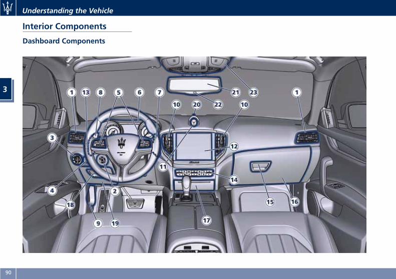
Interior Components
Dashboard Components
Understanding the Vehicle
3
90
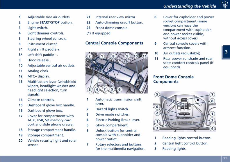
1 Adjustable side air outlets.
2 Engine START/STOP button.
3 Light switch.
4 Light dimmer controls.
5 Steering wheel controls.
6 Instrument cluster.
7* Right shift paddle +.
8* Left shift paddle –.
9 Hood release.
10 Adjustable central air outlets.
11 Analog clock.
12 MTC+ display.
13 Multifuction lever (windshieldwipers, headlight washer andheadlight selection, turnsignals).
14 Climate controls.
15 Dashboard glove box handle.
16 Dashboard glove box.
17 Cover for compartment withAUX, USB, SD memory cardport and slide phone drawer.
18 Storage compartment handle.
19 Storage compartment.
20 Vehicle security light and solarsensor.
21 Internal rear view mirror.
22 Auto-dimming on/off button.
23 Front dome console.
(*) If equipped
Central Console Components
1 Automatic transmission shiftlever.
2 Hazard lights switch.
3 Drive mode switches.
4 Electric Parking Brake lever.
5 Glove compartment.
6 Unlock button for centralconsole with cupholder andpower outlet.
7 Rotary selectors and buttonsfor the multimedia navigation.
8 Cover for cupholder and powersocket compartment (someversions can have thecompartment with cupholderand power socket visible,without access cover).
9 Central console covers witharmrest function.
10 Air outlets (adjustable).
11 Rear power sunshade and rearseats comfort controls panel (ifequipped).
Front Dome ConsoleComponents
1 Reading lights control button.
2 Central light control button.
3 Reading lights.
Understanding the Vehicle
3
91
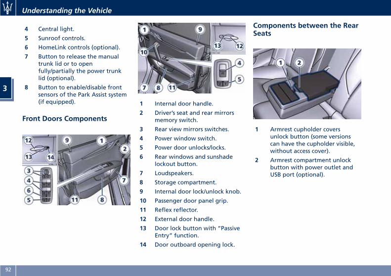
4 Central light.
5 Sunroof controls.
6 HomeLink controls (optional).
7 Button to release the manualtrunk lid or to openfully/partially the power trunklid (optional).
8 Button to enable/disable frontsensors of the Park Assist system(if equipped).
Front Doors Components
1 Internal door handle.
2 Driver’s seat and rear mirrorsmemory switch.
3 Rear view mirrors switches.
4 Power window switch.
5 Power door unlocks/locks.
6 Rear windows and sunshadelockout button.
7 Loudspeakers.
8 Storage compartment.
9 Internal door lock/unlock knob.
10 Passenger door panel grip.
11 Reflex reflector.
12 External door handle.
13 Door lock button with “PassiveEntry” function.
14 Door outboard opening lock.
Components between the RearSeats
1 Armrest cupholder coversunlock button (some versionscan have the cupholder visible,without access cover).
2 Armrest compartment unlockbutton with power outlet andUSB port (optional).
Understanding the Vehicle
3
92
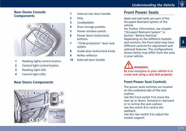
Rear Dome ConsoleComponents
1 Reading lights control button.
2 Central light control button.
3 Reading light LED.
4 Central light LEDs.
Rear Doors Components
1 Internal rear door handle.
2 Grip.
3 Loudspeaker.
4 Door storage pockets.
5 Power window switch.
6 Power doors lock/unlockbuttons.
7 “Child protection” door locksystem.
8 Inside door lock/unlock knob.
9 Reflex reflector.
10 External door handle.
Front Power SeatsSeats and seat belts are part of theOccupant Restraint System of thevehicle.For further information, see chapter“Occupant Restraint System” inSection “Before Starting”.Depending on the different marketsand versions, the front seats may havedifferent controls for adjustment andoptional features. The configurationsshown below may differ from the onesin your vehicle.
WARNING!Be sure everyone in your vehicle is ina seat and using a seat belt properly.
Front Power Seat ControlsThe power seats switches are locatedon the outboard side of the seatcushion.Use the front switch 1 to move theseat up or down, forward or rearwardor to recline the seat cushion.Use the switch 2 to recline theseatback.Use the rear switch 3 to adjust thelumbar support.
Understanding the Vehicle
3
93
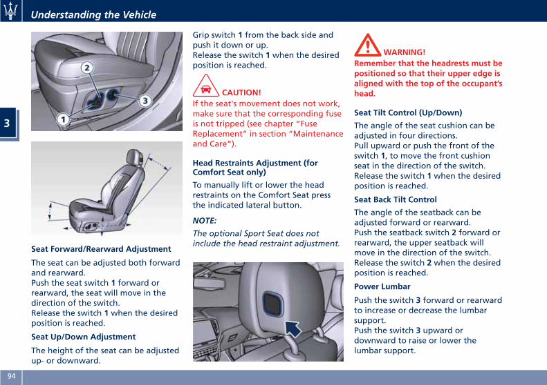
Seat Forward/Rearward Adjustment
The seat can be adjusted both forwardand rearward.Push the seat switch 1 forward orrearward, the seat will move in thedirection of the switch.Release the switch 1 when the desiredposition is reached.
Seat Up/Down Adjustment
The height of the seat can be adjustedup- or downward.
Grip switch 1 from the back side andpush it down or up.Release the switch 1 when the desiredposition is reached.
CAUTION!If the seat's movement does not work,make sure that the corresponding fuseis not tripped (see chapter “FuseReplacement” in section “Maintenanceand Care”).
Head Restraints Adjustment (forComfort Seat only)
To manually lift or lower the headrestraints on the Comfort Seat pressthe indicated lateral button.
NOTE:
The optional Sport Seat does notinclude the head restraint adjustment.
WARNING!Remember that the headrests must bepositioned so that their upper edge isaligned with the top of the occupant’shead.
Seat Tilt Control (Up/Down)
The angle of the seat cushion can beadjusted in four directions.Pull upward or push the front of theswitch 1, to move the front cushionseat in the direction of the switch.Release the switch 1 when the desiredposition is reached.
Seat Back Tilt Control
The angle of the seatback can beadjusted forward or rearward.Push the seatback switch 2 forward orrearward, the upper seatback willmove in the direction of the switch.Release the switch 2 when the desiredposition is reached.
Power Lumbar
Push the switch 3 forward or rearwardto increase or decrease the lumbarsupport.Push the switch 3 upward ordownward to raise or lower thelumbar support.
Understanding the Vehicle
3
94
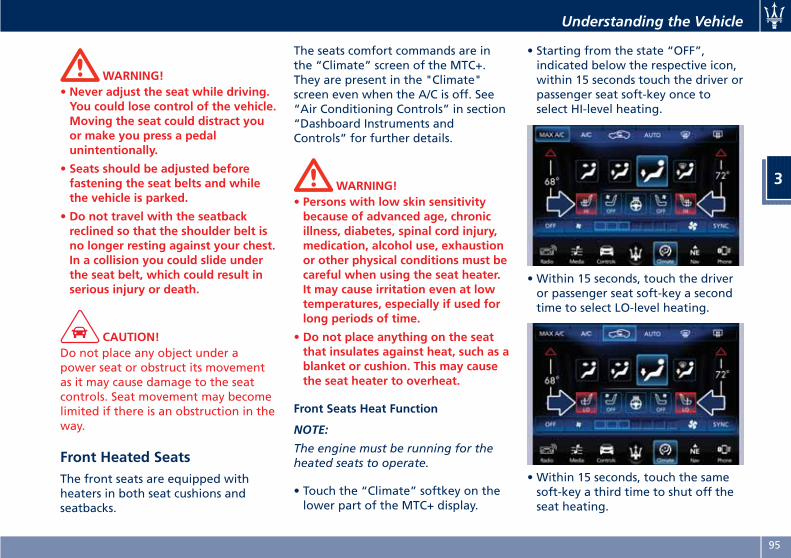
WARNING!• Never adjust the seat while driving.You could lose control of the vehicle.Moving the seat could distract youor make you press a pedalunintentionally.
• Seats should be adjusted beforefastening the seat belts and whilethe vehicle is parked.
• Do not travel with the seatbackreclined so that the shoulder belt isno longer resting against your chest.In a collision you could slide underthe seat belt, which could result inserious injury or death.
CAUTION!Do not place any object under apower seat or obstruct its movementas it may cause damage to the seatcontrols. Seat movement may becomelimited if there is an obstruction in theway.
Front Heated SeatsThe front seats are equipped withheaters in both seat cushions andseatbacks.
The seats comfort commands are inthe “Climate” screen of the MTC+.They are present in the "Climate"screen even when the A/C is off. See“Air Conditioning Controls” in section“Dashboard Instruments andControls” for further details.
WARNING!• Persons with low skin sensitivitybecause of advanced age, chronicillness, diabetes, spinal cord injury,medication, alcohol use, exhaustionor other physical conditions must becareful when using the seat heater.It may cause irritation even at lowtemperatures, especially if used forlong periods of time.
• Do not place anything on the seatthat insulates against heat, such as ablanket or cushion. This may causethe seat heater to overheat.
Front Seats Heat Function
NOTE:
The engine must be running for theheated seats to operate.
• Touch the “Climate” softkey on thelower part of the MTC+ display.
• Starting from the state “OFF”,indicated below the respective icon,within 15 seconds touch the driver orpassenger seat soft-key once toselect HI-level heating.
• Within 15 seconds, touch the driveror passenger seat soft-key a secondtime to select LO-level heating.
• Within 15 seconds, touch the samesoft-key a third time to shut off theseat heating.
Understanding the Vehicle
3
95
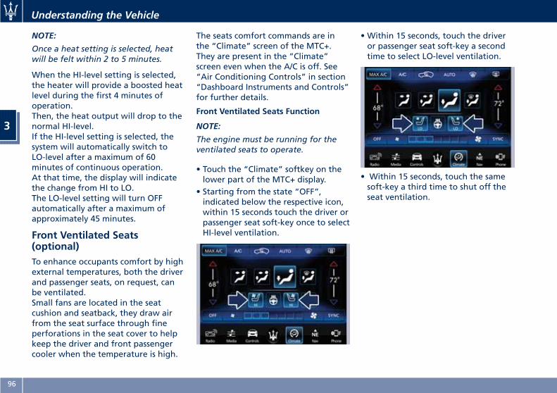
NOTE:
Once a heat setting is selected, heatwill be felt within 2 to 5 minutes.
When the HI-level setting is selected,the heater will provide a boosted heatlevel during the first 4 minutes ofoperation.Then, the heat output will drop to thenormal HI-level.If the HI-level setting is selected, thesystem will automatically switch toLO-level after a maximum of 60minutes of continuous operation.At that time, the display will indicatethe change from HI to LO.The LO-level setting will turn OFFautomatically after a maximum ofapproximately 45 minutes.
Front Ventilated Seats(optional)To enhance occupants comfort by highexternal temperatures, both the driverand passenger seats, on request, canbe ventilated.Small fans are located in the seatcushion and seatback, they draw airfrom the seat surface through fineperforations in the seat cover to helpkeep the driver and front passengercooler when the temperature is high.
The seats comfort commands are inthe “Climate” screen of the MTC+.They are present in the “Climate”screen even when the A/C is off. See“Air Conditioning Controls” in section“Dashboard Instruments and Controls”for further details.
Front Ventilated Seats Function
NOTE:
The engine must be running for theventilated seats to operate.
• Touch the “Climate” softkey on thelower part of the MTC+ display.
• Starting from the state “OFF”,indicated below the respective icon,within 15 seconds touch the driver orpassenger seat soft-key once to selectHI-level ventilation.
• Within 15 seconds, touch the driveror passenger seat soft-key a secondtime to select LO-level ventilation.
• Within 15 seconds, touch the samesoft-key a third time to shut off theseat ventilation.
Understanding the Vehicle
3
96
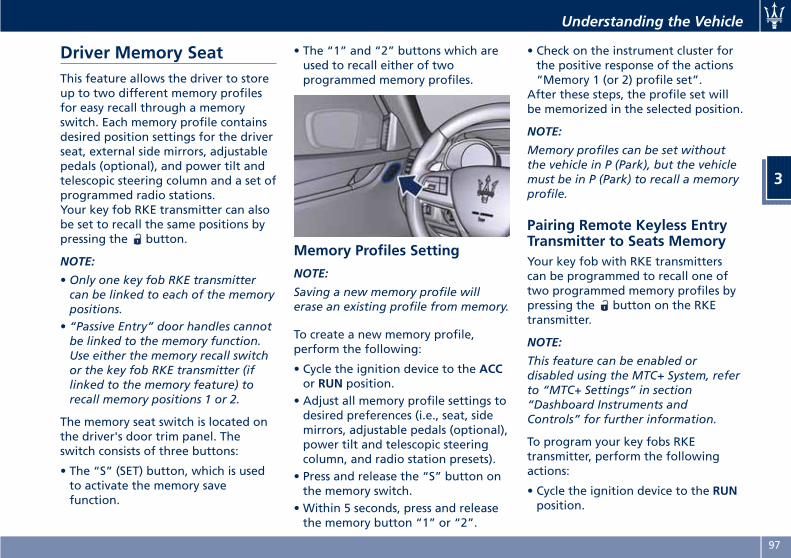
Driver Memory SeatThis feature allows the driver to storeup to two different memory profilesfor easy recall through a memoryswitch. Each memory profile containsdesired position settings for the driverseat, external side mirrors, adjustablepedals (optional), and power tilt andtelescopic steering column and a set ofprogrammed radio stations.Your key fob RKE transmitter can alsobe set to recall the same positions bypressing the button.
NOTE:
• Only one key fob RKE transmittercan be linked to each of the memorypositions.
• “Passive Entry” door handles cannotbe linked to the memory function.Use either the memory recall switchor the key fob RKE transmitter (iflinked to the memory feature) torecall memory positions 1 or 2.
The memory seat switch is located onthe driver's door trim panel. Theswitch consists of three buttons:
• The “S” (SET) button, which is usedto activate the memory savefunction.
• The “1” and “2” buttons which areused to recall either of twoprogrammed memory profiles.
Memory Profiles Setting
NOTE:
Saving a new memory profile willerase an existing profile from memory.
To create a new memory profile,perform the following:
• Cycle the ignition device to the ACCor RUN position.
• Adjust all memory profile settings todesired preferences (i.e., seat, sidemirrors, adjustable pedals (optional),power tilt and telescopic steeringcolumn, and radio station presets).
• Press and release the “S” button onthe memory switch.
• Within 5 seconds, press and releasethe memory button “1” or “2”.
• Check on the instrument cluster forthe positive response of the actions“Memory 1 (or 2) profile set”.
After these steps, the profile set willbe memorized in the selected position.
NOTE:
Memory profiles can be set withoutthe vehicle in P (Park), but the vehiclemust be in P (Park) to recall a memoryprofile.
Pairing Remote Keyless EntryTransmitter to Seats MemoryYour key fob with RKE transmitterscan be programmed to recall one oftwo programmed memory profiles bypressing the button on the RKEtransmitter.
NOTE:
This feature can be enabled ordisabled using the MTC+ System, referto “MTC+ Settings” in section“Dashboard Instruments andControls” for further information.
To program your key fobs RKEtransmitter, perform the followingactions:
• Cycle the ignition device to the RUNposition.
Understanding the Vehicle
3
97
• Move the seat and/or the otheradjustable devices in the positionthat you wish to memorize, or recalla previously memorized profile,pressing the corresponding memorybutton “1” or “2”.
• Cycle the ignition device to the OFFposition.
• Press and release the “S” button.• Within 5 seconds, press and releasethe memory button “1” or “2”.
• Press and release the button onkey fob RKE transmitter.
• Within 3 seconds, press and releasethe button on the key fob RKEtransmitter.
To check if the system has memorizedthe correct profile, you can move theseat and press the button: the seatwill move to the memorized position.
NOTE:
Your key fobs RKE transmitter can beunlinked to your memory settings bypressing the “S” button followed bythe button on the key fob RKEtransmitter.
Memory Position Recall
NOTE:
The vehicle must be in P (Park) to recallmemory positions. If a recall isattempted when the vehicle is not in P(Park), a message will display in theinstrument cluster.
To recall the memory settings fordriver, press memory button number“1” or “2” on the driver's door trimpanel or the button on the RKEtransmitter linked to memory position“1” or “2” with ignition device in theRUN position.A recall can be canceled by pressingany of the buttons (“S”, “1”, or “2”)during a recall. When a recall iscanceled, the driver seat, external sidemirrors, adjustable pedals (optional),and power tilt and telescopic steeringcolumn stop moving.A delay of at least one second willoccur before selecting a new recall.
Easy Entry/Exit Driver SeatThis feature provides automatic driverseat positioning to enhance drivermobility when entering and exitingthe vehicle.The distance the driver seat movesdepends on where you have the driverseat positioned when you place theignition device to the OFF position.
• When you cycle the ignition deviceto the OFF position the driver seat:
• will move about 2.36 in (60 mm)rearward if the driver seat positionis greater than or equal to ca. 5.51in (140 mm) forward of the rearstop;
• will move to a position of ca. 3.15in (80 mm) rearward of the rearstop if the driver seat position isbetween 5.51 in (140 mm) and 3.15in (80 mm) forward of the rearstop.
• The seat will return to its previouslyset position when you place theignition device into the ACC or RUNposition.
• The Easy Entry/Exit feature isdisabled when the driver seatposition is less than 3.15 in (80 mm)forward of the rear stop. In thisposition, there would be no benefit
Understanding the Vehicle
3
98
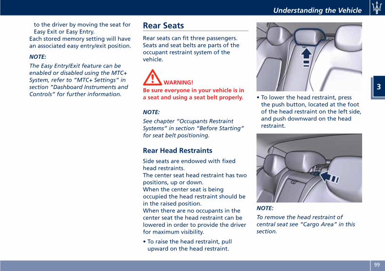
to the driver by moving the seat forEasy Exit or Easy Entry.
Each stored memory setting will havean associated easy entry/exit position.
NOTE:
The Easy Entry/Exit feature can beenabled or disabled using the MTC+System, refer to “MTC+ Settings” insection “Dashboard Instruments andControls” for further information.
Rear SeatsRear seats can fit three passengers.Seats and seat belts are parts of theoccupant restraint system of thevehicle.
WARNING!Be sure everyone in your vehicle is ina seat and using a seat belt properly.
NOTE:
See chapter “Occupants RestraintSystems” in section “Before Starting”for seat belt positioning.
Rear Head RestraintsSide seats are endowed with fixedhead restraints.The center seat head restraint has twopositions, up or down.When the center seat is beingoccupied the head restraint should bein the raised position.When there are no occupants in thecenter seat the head restraint can belowered in order to provide the driverfor maximum visibility.
• To raise the head restraint, pullupward on the head restraint.
• To lower the head restraint, pressthe push button, located at the footof the head restraint on the left side,and push downward on the headrestraint.
NOTE:
To remove the head restraint ofcentral seat see “Cargo Area” in thissection.
Understanding the Vehicle
3
99
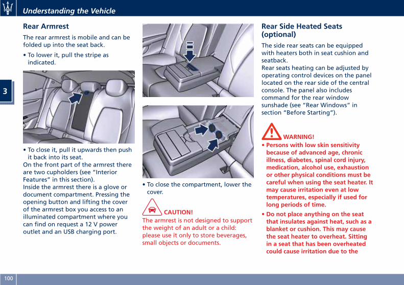
Rear ArmrestThe rear armrest is mobile and can befolded up into the seat back.
• To lower it, pull the stripe asindicated.
• To close it, pull it upwards then pushit back into its seat.
On the front part of the armrest thereare two cupholders (see “InteriorFeatures” in this section).Inside the armrest there is a glove ordocument compartment. Pressing theopening button and lifting the coverof the armrest box you access to anilluminated compartment where youcan find on request a 12 V poweroutlet and an USB charging port.
• To close the compartment, lower thecover.
CAUTION!The armrest is not designed to supportthe weight of an adult or a child:please use it only to store beverages,small objects or documents.
Rear Side Heated Seats(optional)The side rear seats can be equippedwith heaters both in seat cushion andseatback.Rear seats heating can be adjusted byoperating control devices on the panellocated on the rear side of the centralconsole. The panel also includescommand for the rear windowsunshade (see “Rear Windows” insection “Before Starting”).
WARNING!• Persons with low skin sensitivitybecause of advanced age, chronicillness, diabetes, spinal cord injury,medication, alcohol use, exhaustionor other physical conditions must becareful when using the seat heater. Itmay cause irritation even at lowtemperatures, especially if used forlong periods of time.
• Do not place anything on the seatthat insulates against heat, such as ablanket or cushion. This may causethe seat heater to overheat. Sittingin a seat that has been overheatedcould cause irritation due to the
Understanding the Vehicle
3
100
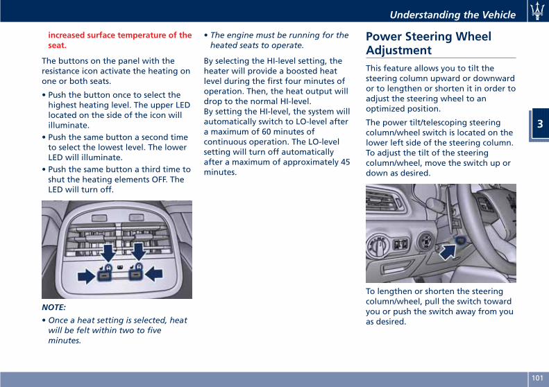
increased surface temperature of theseat.
The buttons on the panel with theresistance icon activate the heating onone or both seats.
• Push the button once to select thehighest heating level. The upper LEDlocated on the side of the icon willilluminate.
• Push the same button a second timeto select the lowest level. The lowerLED will illuminate.
• Push the same button a third time toshut the heating elements OFF. TheLED will turn off.
NOTE:
• Once a heat setting is selected, heatwill be felt within two to fiveminutes.
• The engine must be running for theheated seats to operate.
By selecting the HI-level setting, theheater will provide a boosted heatlevel during the first four minutes ofoperation. Then, the heat output willdrop to the normal HI-level.By setting the HI-level, the system willautomatically switch to LO-level aftera maximum of 60 minutes ofcontinuous operation. The LO-levelsetting will turn off automaticallyafter a maximum of approximately 45minutes.
Power Steering WheelAdjustmentThis feature allows you to tilt thesteering column upward or downwardor to lengthen or shorten it in order toadjust the steering wheel to anoptimized position.
The power tilt/telescoping steeringcolumn/wheel switch is located on thelower left side of the steering column.To adjust the tilt of the steeringcolumn/wheel, move the switch up ordown as desired.
To lengthen or shorten the steeringcolumn/wheel, pull the switch towardyou or push the switch away from youas desired.
Understanding the Vehicle
3
101
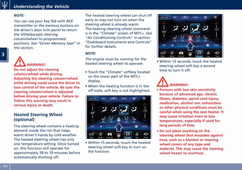
NOTE:
You can use your key fob with RKEtransmitter or the memory buttons onthe driver's door trim panel to returnthe tilt/telescopic steeringcolumn/wheel to programmedpositions. See “Driver Memory Seat” inthis section.
WARNING!Do not adjust the steeringcolumn/wheel while driving.Adjusting the steering column/wheelwhile driving could cause the driver tolose control of the vehicle. Be sure thesteering column/wheel is adjustedbefore driving your vehicle. Failure tofollow this warning may result inserious injury or death.
Heated Steering Wheel(optional)The steering wheel contains a heatingelement inside the rim that helpswarm driver’s hands by cold weather.The heated steering wheel has onlyone temperature setting. Once turnedon, this function will operate forapproximately 58 to 70 minutes beforeautomatically shutting off.
The heated steering wheel can shut offearly or may not turn on when thesteering wheel is already warm.The heating steering wheel commandis in the “Climate” screen of MTC+. See“Air Conditioning Controls” in section“Dashboard Instruments and Controls”for further details.
NOTE:
The engine must be running for theheated steering wheel to operate.
• Touch the “Climate” softkey locatedon the lower part of the MTC+display.
• When the heating function is in theoff state, soft-key is not highlighted.
• Within 15 seconds, touch the heatedsteering wheel soft-key to turn onthe function.
• Within 15 seconds, touch the heatedsteering wheel soft-key a secondtime to turn it off.
WARNING!• Persons with low skin sensitivitybecause of advanced age, chronicillness, diabetes, spinal cord injury,medication, alcohol use, exhaustionor other physical conditions must becareful when using the seat heater. Itmay cause irritation even at lowtemperatures, especially if used forlong periods of time.
• Do not place anything on thesteering wheel that insulates againstheat, such as a blanket or steeringwheel covers of any type andmaterial. This may cause the steeringwheel heater to overheat.
Understanding the Vehicle
3
102
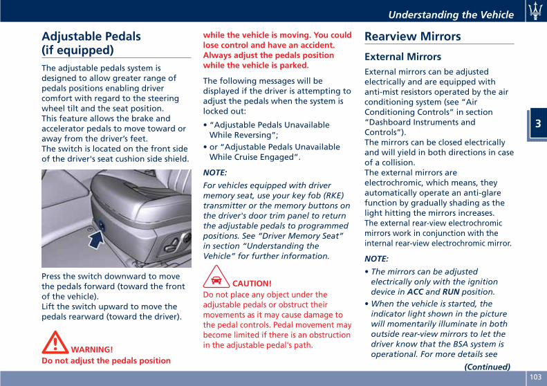
Adjustable Pedals(if equipped)The adjustable pedals system isdesigned to allow greater range ofpedals positions enabling drivercomfort with regard to the steeringwheel tilt and the seat position.This feature allows the brake andaccelerator pedals to move toward oraway from the driver’s feet.The switch is located on the front sideof the driver's seat cushion side shield.
Press the switch downward to movethe pedals forward (toward the frontof the vehicle).Lift the switch upward to move thepedals rearward (toward the driver).
WARNING!Do not adjust the pedals position
while the vehicle is moving. You couldlose control and have an accident.Always adjust the pedals positionwhile the vehicle is parked.
The following messages will bedisplayed if the driver is attempting toadjust the pedals when the system islocked out:
• “Adjustable Pedals UnavailableWhile Reversing”;
• or “Adjustable Pedals UnavailableWhile Cruise Engaged”.
NOTE:
For vehicles equipped with drivermemory seat, use your key fob (RKE)transmitter or the memory buttons onthe driver's door trim panel to returnthe adjustable pedals to programmedpositions. See “Driver Memory Seat”in section “Understanding theVehicle” for further information.
CAUTION!Do not place any object under theadjustable pedals or obstruct theirmovements as it may cause damage tothe pedal controls. Pedal movement maybecome limited if there is an obstructionin the adjustable pedal's path.
Rearview Mirrors
External MirrorsExternal mirrors can be adjustedelectrically and are equipped withanti-mist resistors operated by the airconditioning system (see “AirConditioning Controls” in section“Dashboard Instruments andControls”).The mirrors can be closed electricallyand will yield in both directions in caseof a collision.The external mirrors areelectrochromic, which means, theyautomatically operate an anti-glarefunction by gradually shading as thelight hitting the mirrors increases.The external rear-view electrochromicmirrors work in conjunction with theinternal rear-view electrochromic mirror.
NOTE:
• The mirrors can be adjustedelectrically only with the ignitiondevice in ACC and RUN position.
•When the vehicle is started, theindicator light shown in the picturewill momentarily illuminate in bothoutside rear-view mirrors to let thedriver know that the BSA system isoperational. For more details see
(Continued)
Understanding the Vehicle
3
103
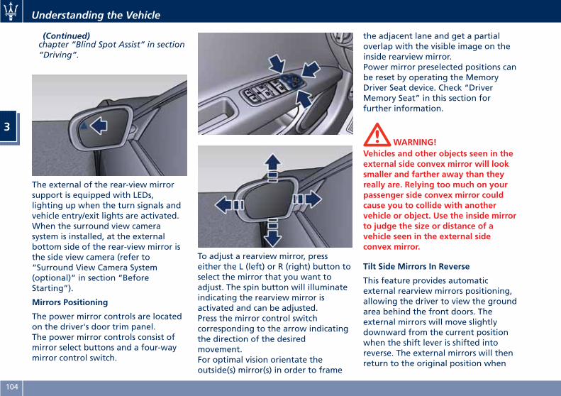
(Continued)chapter “Blind Spot Assist” in section“Driving”.
The external of the rear-view mirrorsupport is equipped with LEDs,lighting up when the turn signals andvehicle entry/exit lights are activated.When the surround view camerasystem is installed, at the externalbottom side of the rear-view mirror isthe side view camera (refer to“Surround View Camera System(optional)” in section “BeforeStarting”).
Mirrors Positioning
The power mirror controls are locatedon the driver's door trim panel.The power mirror controls consist ofmirror select buttons and a four-waymirror control switch.
To adjust a rearview mirror, presseither the L (left) or R (right) button toselect the mirror that you want toadjust. The spin button will illuminateindicating the rearview mirror isactivated and can be adjusted.Press the mirror control switchcorresponding to the arrow indicatingthe direction of the desiredmovement.For optimal vision orientate theoutside(s) mirror(s) in order to frame
the adjacent lane and get a partialoverlap with the visible image on theinside rearview mirror.Power mirror preselected positions canbe reset by operating the MemoryDriver Seat device. Check “DriverMemory Seat” in this section forfurther information.
WARNING!Vehicles and other objects seen in theexternal side convex mirror will looksmaller and farther away than theyreally are. Relying too much on yourpassenger side convex mirror couldcause you to collide with anothervehicle or object. Use the inside mirrorto judge the size or distance of avehicle seen in the external sideconvex mirror.
Tilt Side Mirrors In Reverse
This feature provides automaticexternal rearview mirrors positioning,allowing the driver to view the groundarea behind the front doors. Theexternal mirrors will move slightlydownward from the current positionwhen the shift lever is shifted intoreverse. The external mirrors will thenreturn to the original position when
Understanding the Vehicle
3
104
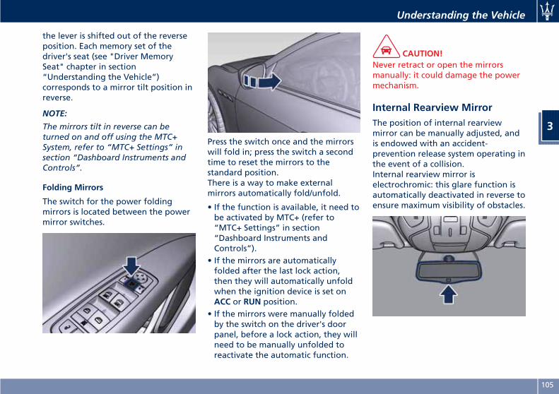
the lever is shifted out of the reverseposition. Each memory set of thedriver's seat (see "Driver MemorySeat" chapter in section“Understanding the Vehicle”)corresponds to a mirror tilt position inreverse.
NOTE:
The mirrors tilt in reverse can beturned on and off using the MTC+System, refer to “MTC+ Settings” insection “Dashboard Instruments andControls”.
Folding Mirrors
The switch for the power foldingmirrors is located between the powermirror switches.
Press the switch once and the mirrorswill fold in; press the switch a secondtime to reset the mirrors to thestandard position.There is a way to make externalmirrors automatically fold/unfold.
• If the function is available, it need tobe activated by MTC+ (refer to“MTC+ Settings” in section“Dashboard Instruments andControls”).
• If the mirrors are automaticallyfolded after the last lock action,then they will automatically unfoldwhen the ignition device is set onACC or RUN position.
• If the mirrors were manually foldedby the switch on the driver's doorpanel, before a lock action, they willneed to be manually unfolded toreactivate the automatic function.
CAUTION!Never retract or open the mirrorsmanually: it could damage the powermechanism.
Internal Rearview MirrorThe position of internal rearviewmirror can be manually adjusted, andis endowed with an accident-prevention release system operating inthe event of a collision.Internal rearview mirror iselectrochromic: this glare function isautomatically deactivated in reverse toensure maximum visibility of obstacles.
Understanding the Vehicle
3
105
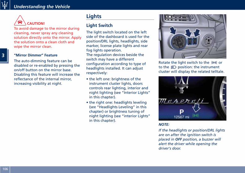
CAUTION!To avoid damage to the mirror duringcleaning, never spray any cleaningsolution directly onto the mirror. Applythe solution onto a clean cloth andwipe the mirror clean.
“Mirror Dimmer” Feature
The auto-dimming feature can bedisabled or re-enabled by pressing theon/off button on the mirror base.Disabling this feature will increase thereflectance of the internal mirror,increasing visibility at night.
Lights
Light SwitchThe light switch located on the leftside of the dashboard is used for theposition/DRL lights, headlights, sidemarker, license plate lights and rearfog lights operation.The regulation devices beside theswitch may have a differentconfiguration according to type ofheadlights installed. It can adjustrespectively:
• the left one: brightness of theinstrument cluster lights, doorscontrols rear lighting, interior andnight lighting (see “Interior Lights”in this chapter).
• the right one: headlights leveling(see “Headlights Leveling” in thischapter) or brightness tuning ofnight lighting (see “interior Lights”in this chapter).
Rotate the light switch to the orto the position: the instrumentcluster will display the related telltale.
NOTE:
If the headlights or position/DRL lightsare on after the ignition switch isplaced in OFF position, a buzzer willalert the driver while opening thedriver's door.
Understanding the Vehicle
3
106
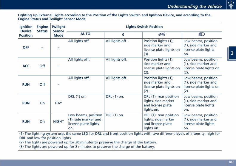
Lighting Up External Lights according to the Position of the Lights Switch and Ignition Device, and according to theEngine Status and Twilight Sensor Mode
IgnitionDevicePosition
EngineStatus
TwilightSensorMode
Lights Switch Position
AUTO 0
OFF – –
All lights off. All lights off. Position lights (1),side marker andlicense plate lights on(3).
Low beams, position(1), side marker andlicense plate lightson.
ACC Off –
All lights off. All lights off. Position lights (1),side marker andlicense plate lights on(2).
Low beams, position(1), side marker andlicense plate lights on(2).
RUN Off –
All lights off. All lights off. Position lights (1),side marker andlicense plate lights on(2).
Low beams, position(1), side marker andlicense plate lights on(2).
RUN On DAY
DRL (1) on. DRL (1) on. DRL (1), rear positionlights, side markerand license platelights on.
Low beams, position(1), side marker andlicense plate lightson.
RUN On NIGHT
Low beams, position(1), side marker andlicense plate lightson.
DRL (1) on. DRL (1), rear positionlights, side markerand license platelights on.
Low beams, position(1), side marker andlicense plate lightson.
(1) The lighting system uses the same LED for DRL and front position lights with two different levels of intensity: high forDRL and low for position lights.(2) The lights are powered up for 30 minutes to preserve the charge of the battery.(3) The lights are powered up for 8 minutes to preserve the charge of the battery.
Understanding the Vehicle
3
107
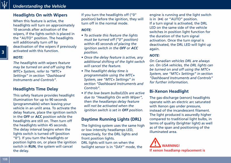
Headlights On with WipersWhen this feature is active, theheadlights will turn on approximately10 seconds after activation of thewipers, if the lights switch is placed inthe “AUTO” position. The headlightswill additionally turn off bydeactivation of the wipers if previouslyactivated with this function.
NOTE:
The headlights with wipers featuremay be turned on and off using theMTC+ System, refer to “MTC+Settings” in section “DashboardInstruments and Controls”.
Headlights Time DelayThis safety feature provides headlightillumination for up to 90 seconds(programmable) when leaving yourvehicle in an unlit area. To activate thedelay feature, place the ignition switchin the OFF or ACC position while theheadlights are still on. Then turn offthe headlights within 45 seconds.The delay interval begins when thelights switch is turned off (position“0”). If you turn the headlights orposition lights on, or place the ignitionswitch in RUN, the system will cancelthe delay.
If you turn the headlights off (“0”position) before the ignition, they willturn off in the normal mode.
NOTE:
• To activate this feature the lightsmust be turned off (“0” position)within 45 seconds of placing theignition switch in the OFF or ACCposition.
• Once the delay feature is active, anyadditional shifting of the light switchwill cancel the feature.
• The headlight delay time isprogrammable using the MTC+System, see “MTC+ Settings” insection “Dashboard Instruments andControls”.
• If the low beam bulbs/LEDs are activedue to “Headlights On with Wiper”,then the headlamps delay featurewill not be activated when theignition switch is set in OFF position.
Daytime Running Lights (DRL)The lighting system uses the same highor low intensity headlamps LED,respectively, for the DRL lights andfront position lights.DRL lights will turn on when thetwilight sensor is in “DAY” mode, the
engine is running and the light switchis in or “AUTO” position.If a turn signal is activated, the DRLLED on the same side of the vehicleswitches in position light function forthe duration of the turn signalactivation. Once the turn signal isdeactivated, the DRL LED will light upagain.
NOTE:
On Canadian vehicles DRL are alwayson. On USA vehicles, the DRL lights canbe turned on and off using the MTC+System, see “MTC+ Settings” in section“Dashboard Instruments and Controls”for further information.
Bi-Xenon HeadlightThe gas-discharge (xenon) headlightsoperate with an electric arc saturatedwith Xenon gas under pressure,instead of the incandescent filament.The light produced is assuredly highercompared to traditional light bulbs, interms of quality (brighter light) as wellas of the span and positioning of theilluminated area.
WARNING!If xenon headlamp replacement is
Understanding the Vehicle
3
108
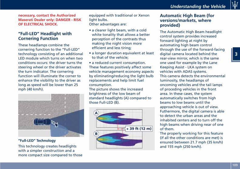
necessary, contact the AuthorizedMaserati Dealer only: DANGER - RISKOF ELECTRICAL SHOCK.
“Full-LED” Headlight withCornering FunctionThese headlamps combine thecornering function to the “Full-LED”technology consisting of an additionalLED module which turns on when twoconditions occurs: the driver turns thesteering wheel or the driver activatesthe turn indicator. The corneringfunction will illuminate the corner toenhance the visibility to the driver aslong as speed will be lower than 25mph (40 km/h).
“Full-LED” Technology
This technology creates headlightswith a simpler construction and amore compact size compared to those
equipped with traditional or Xenonlight bulbs.Other advantages are:
• a clearer light beam, with a coldwhite tonality that allows a betterperception of the contrasts thusmaking the night vision moreefficient and less tiring;
• a longer duration equivalent at leastto that of the vehicle;
• a reduced current consumption.These features positively affect somevehicle management economy aspectsby eliminating/reducing the light bulbreplacements and help limit fuelconsumption.The picture shows the increasedbrightness of the low beam ofstandard headlights (A) compared tothose Full-LED (B).
Automatic High Beam (forversions/markets, whereprovided)The Automatic High Beam headlightcontrol system provides increasedforward lighting at night byautomating high beam controlthrough the use of the forward-facingdigital camera located behind therear-view mirror, which is the sameone used for example by the LaneKeeping Assist - LKA system onvehicles with ADAS systems.This camera detects the environmentalluminosity, the headlamps ofoncoming vehicles and the tail lampsof proceding vehicles in the frontarea. In these cases, the systemautomatically switches from highbeams to low beams until theapproaching vehicle is out of view.Futhermore, the digital camera is ableto detect the urban areas and theinhabited centers and to turn off thehigh beams when driving near of oneof them.The properly working for this feature(if all the other conditions are met) isensured between 21.7 mph (35 km/h)and 155 mph (250 km/h).
Understanding the Vehicle
3
109
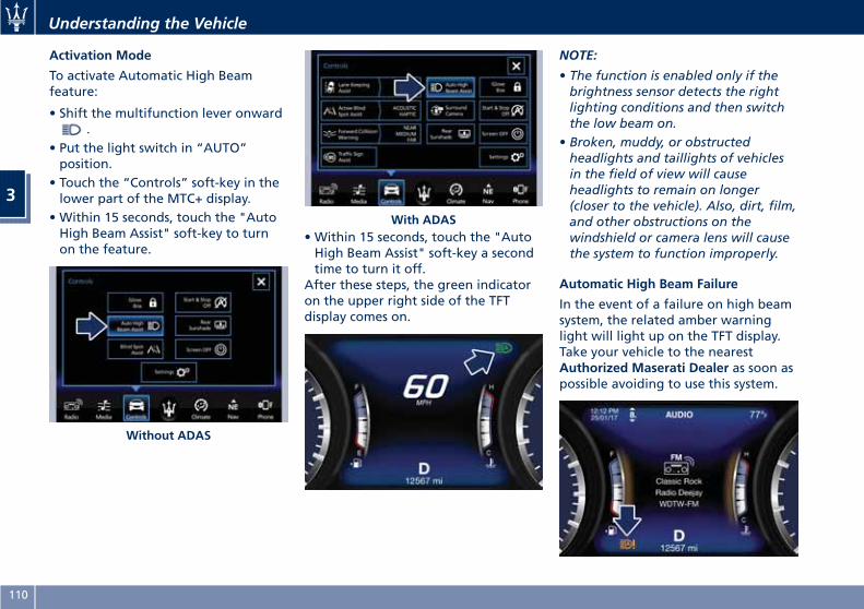
Activation Mode
To activate Automatic High Beamfeature:
• Shift the multifunction lever onward.
• Put the light switch in “AUTO”position.
• Touch the “Controls” soft-key in thelower part of the MTC+ display.
• Within 15 seconds, touch the "AutoHigh Beam Assist" soft-key to turnon the feature.
• Within 15 seconds, touch the "AutoHigh Beam Assist" soft-key a secondtime to turn it off.
After these steps, the green indicatoron the upper right side of the TFTdisplay comes on.
NOTE:
• The function is enabled only if thebrightness sensor detects the rightlighting conditions and then switchthe low beam on.
• Broken, muddy, or obstructedheadlights and taillights of vehiclesin the field of view will causeheadlights to remain on longer(closer to the vehicle). Also, dirt, film,and other obstructions on thewindshield or camera lens will causethe system to function improperly.
Automatic High Beam Failure
In the event of a failure on high beamsystem, the related amber warninglight will light up on the TFT display.Take your vehicle to the nearestAuthorized Maserati Dealer as soon aspossible avoiding to use this system.
Without ADAS
With ADAS
Understanding the Vehicle
3
110
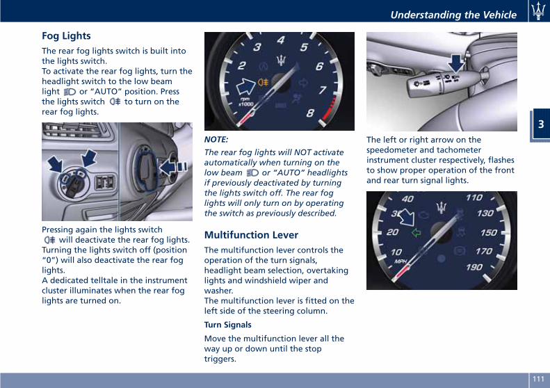
Fog LightsThe rear fog lights switch is built intothe lights switch.To activate the rear fog lights, turn theheadlight switch to the low beamlight or “AUTO” position. Pressthe lights switch to turn on therear fog lights.
Pressing again the lights switchwill deactivate the rear fog lights.
Turning the lights switch off (position“0”) will also deactivate the rear foglights.A dedicated telltale in the instrumentcluster illuminates when the rear foglights are turned on.
NOTE:
The rear fog lights will NOT activateautomatically when turning on thelow beam or “AUTO” headlightsif previously deactivated by turningthe lights switch off. The rear foglights will only turn on by operatingthe switch as previously described.
Multifunction LeverThe multifunction lever controls theoperation of the turn signals,headlight beam selection, overtakinglights and windshield wiper andwasher.The multifunction lever is fitted on theleft side of the steering column.
Turn Signals
Move the multifunction lever all theway up or down until the stoptriggers.
The left or right arrow on thespeedometer and tachometerinstrument cluster respectively, flashesto show proper operation of the frontand rear turn signal lights.
Understanding the Vehicle
3
111
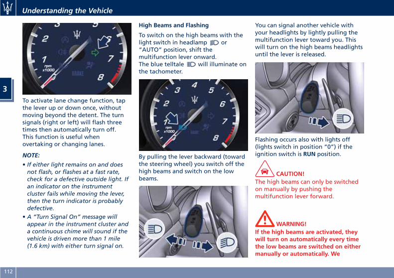
To activate lane change function, tapthe lever up or down once, withoutmoving beyond the detent. The turnsignals (right or left) will flash threetimes then automatically turn off.This function is useful whenovertaking or changing lanes.
NOTE:
• If either light remains on and doesnot flash, or flashes at a fast rate,check for a defective outside light. Ifan indicator on the instrumentcluster fails while moving the lever,then the turn indicator is probablydefective.
• A “Turn Signal On” message willappear in the instrument cluster anda continuous chime will sound if thevehicle is driven more than 1 mile(1.6 km) with either turn signal on.
High Beams and Flashing
To switch on the high beams with thelight switch in headlamp or“AUTO” position, shift themultifunction lever onward.The blue telltale will illuminate onthe tachometer.
By pulling the lever backward (towardthe steering wheel) you switch off thehigh beams and switch on the lowbeams.
You can signal another vehicle withyour headlights by lightly pulling themultifunction lever toward you. Thiswill turn on the high beams headlightsuntil the lever is released.
Flashing occurs also with lights off(lights switch in position “0”) if theignition switch is RUN position.
CAUTION!The high beams can only be switchedon manually by pushing themultifunction lever forward.
WARNING!If the high beams are activated, theywill turn on automatically every timethe low beams are switched on eithermanually or automatically. We
Understanding the Vehicle
3
112
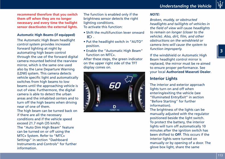
recommend therefore that you switchthem off when they are no longernecessary and every time the twilightsensor deactivates the external lights.
Automatic High Beams (if equipped)
The Automatic High Beam headlightcontrol system provides increasedforward lighting at night byautomating high beam controlthrough the use of the forward digitalcamera mounted behind the rearviewmirror, which is the same one usedalso by the Lane Departure Warning(LDW) system. This camera detectsvehicle specific light and automaticallyswitches from high beams to lowbeams until the approaching vehicle isout of view. Furthermore, the digitalcamera is able to detect the urbanareas and the inhabited centers and toturn off the high beams when drivingnear of one of them.The high beam can be turned back onif there are all the necessaryconditions and if the vehicle speedexceed 21.7 mph (35 km/h).The “Auto Dim High Beam” featurecan be turned on or off using theMTC+ System. Refer to “MTC+Settings” in section "DashboardInstruments and Controls" for furtherinformation.
The function is enabled only if thebrightness sensor detects the rightlighting conditions.To activate this function:
• Shift the multifunction lever onward.
• Put the headlight switch in “AUTO”position.
• Enable the “Automatic High Beam”function on MTC+.
After these steps, the green indicatoron the upper right side of the TFTdisplay comes on.
NOTE:
Broken, muddy, or obstructedheadlights and taillights of vehicles inthe field of view will cause headlightsto remain on longer (closer to thevehicle). Also, dirt, film, and otherobstructions on the windshield orcamera lens will cause the system tofunction improperly.
If the windshield or Automatic HighBeam headlight control mirror isreplaced, the mirror must be re-aimedto ensure proper performance. Seeyour local Authorized Maserati Dealer.
Interior LightsThe interior and exterior approachlights turn on and off whenentering/exiting the vehicle (see“Illuminated Entry/Exit” in section"Before Starting" for furtherinformation).The brightness of the lights can bemanually adjusted with the regulatorpositioned beside the light switch.To protect the battery, the interiorlights will turn off automatically 10minutes after the ignition switch hasbeen shifted to OFF. This occurs if theinterior lights were turned onmanually or by opening of a door. Theglove box light, share the same
Understanding the Vehicle
3
113
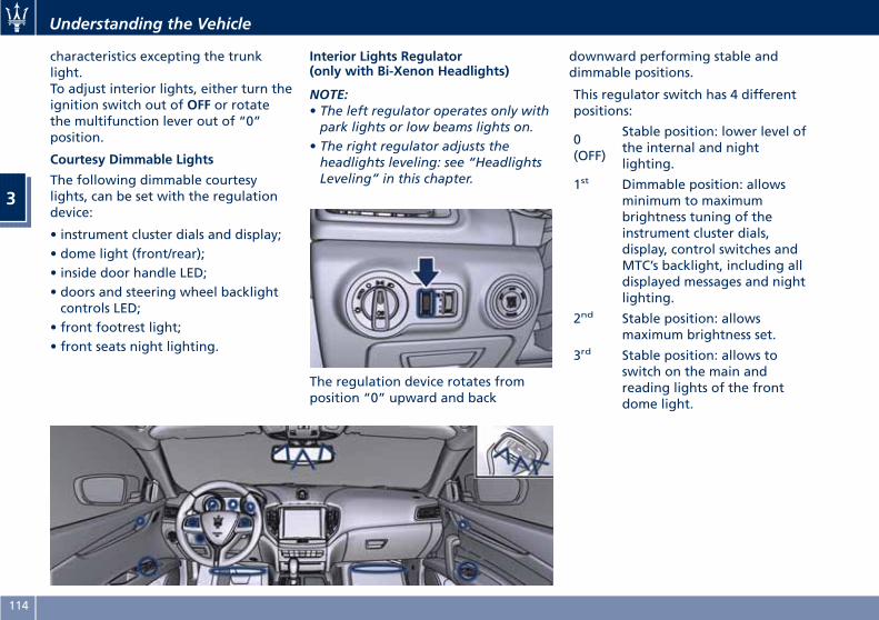
characteristics excepting the trunklight.To adjust interior lights, either turn theignition switch out of OFF or rotatethe multifunction lever out of “0”position.
Courtesy Dimmable Lights
The following dimmable courtesylights, can be set with the regulationdevice:
• instrument cluster dials and display;• dome light (front/rear);• inside door handle LED;• doors and steering wheel backlightcontrols LED;
• front footrest light;• front seats night lighting.
Interior Lights Regulator(only with Bi-Xenon Headlights)
NOTE:• The left regulator operates only withpark lights or low beams lights on.
• The right regulator adjusts theheadlights leveling: see “HeadlightsLeveling” in this chapter.
The regulation device rotates fromposition “0” upward and back
downward performing stable anddimmable positions.
This regulator switch has 4 differentpositions:
0(OFF)
Stable position: lower level ofthe internal and nightlighting.
1st Dimmable position: allowsminimum to maximumbrightness tuning of theinstrument cluster dials,display, control switches andMTC’s backlight, including alldisplayed messages and nightlighting.
2nd Stable position: allowsmaximum brightness set.
3rd Stable position: allows toswitch on the main andreading lights of the frontdome light.
Understanding the Vehicle
3
114
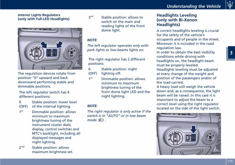
Interior Lights Regulators(only with Full-LED Headlights)
The regulation devices rotate fromposition “0” upward and backdownward performing stable anddimmable positions.
The left regulator switch has 4different positions:
0(OFF)
Stable position: lower levelof the internal lighting.
1st Dimmable position: allowsminimum to maximumbrightness tuning of theinstrument cluster dials,display, control switches andMTC’s backlight, including alldisplayed messages andnight lighting.
2nd Stable position: allowsmaximum brightness set.
3rd Stable position: allows toswitch on the main andreading lights of the frontdome light.
NOTE:
The left regulator operates only withpark lights or low beams lights on.
The right regulator has 2 differentpositions:
0(OFF)
Stable position: nightlighting off.
1st Dimmable position: allowsminimum to maximumbrightness tuning of thefront dome light LED and thenight lighting.
NOTE:
The right regulator is only active if theswitch is in “AUTO” or in low beammode .
Headlights Leveling(only with Bi-XenonHeadlights)A correct headlights leveling is crucialfor the safety of the vehicle’soccupants and of people in the street.Moreover it is included in the roadregulation law.In order to obtain the best visibilityconditions while driving withheadlights on, the headlight beammust be properly leveled.Headlights leveling must be adjustedat every change of the weight andposition of the passengers and/or ofthe load carried.A heavy load will weigh the vehicledown and, as a consequence, the lightbeam will be raised. In this case it isimportant to adjust the beam to acorrect level using the right regulatorlocated on the side of the light switch.
Understanding the Vehicle
3
115
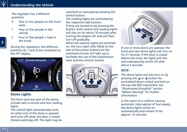
The regulator has 3 differentpositions:
0 One or two people on the frontseats.
1 Four or five people in thevehicle.
2 Four or five people + load inthe trunk.
During the regulation, the differentpositions (0, 1 and 2) are visualized onthe TFT display.
Dome LightsThe front and rear part of the dome,include each a central and two readinglights.The central light automatically turnson when one of the doors is openedand turns off when the door is closed(timed switching off). The light may be
switched on manually by pressing thecentral button.The reading lights are controlled bythe respective side buttons.If they are turned on by pressing thebutton, both central and reading lightswill stay on for about 10 minutes afterturning the engine off, and will thenturn off gradually.When the exterior lights are switchedon, the two night LEDs fitted on theside of the power buttons on theoverhead console will light up tofacilitate the use of the transmissionlever and the central console.
If one or more doors are opened, thefront and rear dome lights will turn onfor 27 seconds. If the door is closedbefore this time, the lights will dimand subsequently switch off afterabout 3 seconds.
NOTE:
The dome lights will also turn on bypressing the or button forcentralized doors unlock and lock onthe key fob RKE transmitter. See“Illuminated Entry/Exit” section“Before Starting” for furtherinformation.
In the event of a collision causingautomatic interruption of fuel supply,the dome lights switch onautomatically and remain lit forapprox. 15 minutes.
Understanding the Vehicle
3
116
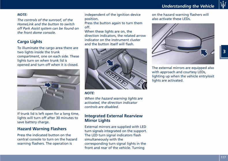
NOTE:
The controls of the sunroof, of theHomeLink and the button to switchoff Park Assist system can be found onthe front dome console.
Cargo LightsTo illuminate the cargo area there aretwo lights inside the trunkcompartment, one on each side. Theselights turn on when trunk lid isopened and turn off when it is closed.
If trunk lid is left open for a long time,lights will turn off after 30 minutes tosave battery charge.
Hazard Warning FlashersPress the indicated button on thecentral console to turn on the hazardwarning flashers. The operation is
independent of the ignition deviceposition.Press the button again to turn themoff.When these lights are on, thedirection indicators, the related arrowindicator on the instrument clusterand the button itself will flash.
NOTE:
When the hazard warning lights areactivated, the direction indicatorcontrols are disabled.
Integrated External RearviewMirror LightsExternal mirrors are supplied with LEDturn signals integrated on the support.The LED turn signal indicators flashsimultaneously with thecorresponding turn signal lights in thefront and rear of the vehicle. Turning
on the hazard warning flashers willalso activate these LEDs.
The external mirrors are equipped alsowith approach and courtesy LEDs,lighting up when the vehicle entry/exitlights are activated.
Understanding the Vehicle
3
117
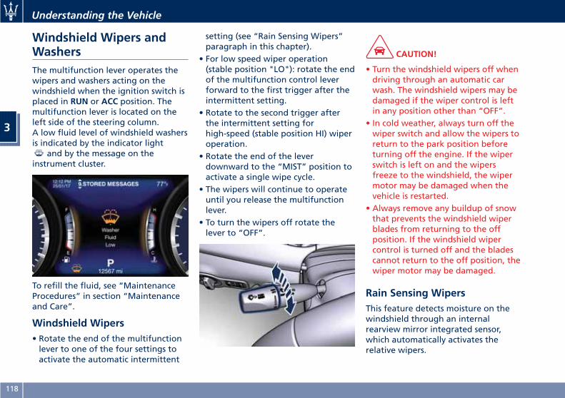
Windshield Wipers andWashersThe multifunction lever operates thewipers and washers acting on thewindshield when the ignition switch isplaced in RUN or ACC position. Themultifunction lever is located on theleft side of the steering column.A low fluid level of windshield washersis indicated by the indicator light
and by the message on theinstrument cluster.
To refill the fluid, see “MaintenanceProcedures” in section “Maintenanceand Care”.
Windshield Wipers• Rotate the end of the multifunctionlever to one of the four settings toactivate the automatic intermittent
setting (see “Rain Sensing Wipers”paragraph in this chapter).
• For low speed wiper operation(stable position "LO"): rotate the endof the multifunction control leverforward to the first trigger after theintermittent setting.
• Rotate to the second trigger afterthe intermittent setting forhigh-speed (stable position HI) wiperoperation.
• Rotate the end of the leverdownward to the “MIST” position toactivate a single wipe cycle.
• The wipers will continue to operateuntil you release the multifunctionlever.
• To turn the wipers off rotate thelever to “OFF”.
CAUTION!
• Turn the windshield wipers off whendriving through an automatic carwash. The windshield wipers may bedamaged if the wiper control is leftin any position other than “OFF”.
• In cold weather, always turn off thewiper switch and allow the wipers toreturn to the park position beforeturning off the engine. If the wiperswitch is left on and the wipersfreeze to the windshield, the wipermotor may be damaged when thevehicle is restarted.
• Always remove any buildup of snowthat prevents the windshield wiperblades from returning to the offposition. If the windshield wipercontrol is turned off and the bladescannot return to the off position, thewiper motor may be damaged.
Rain Sensing WipersThis feature detects moisture on thewindshield through an internalrearview mirror integrated sensor,which automatically activates therelative wipers.
Understanding the Vehicle
3
118
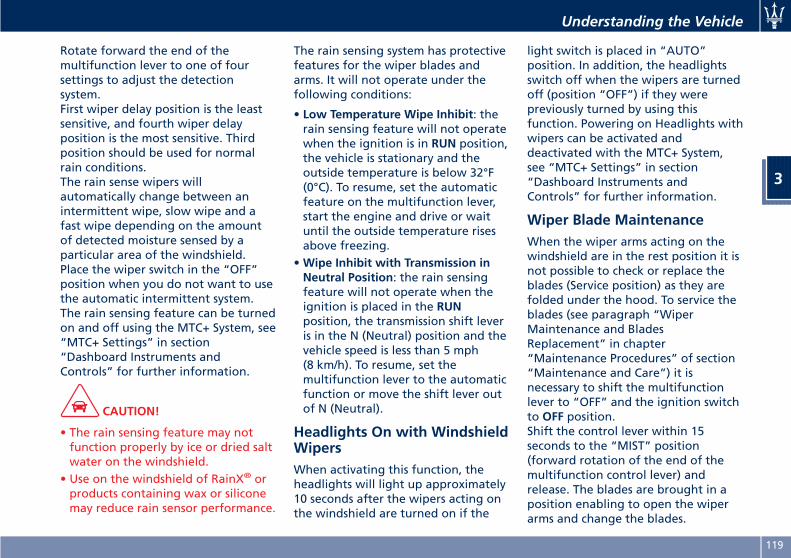
Rotate forward the end of themultifunction lever to one of foursettings to adjust the detectionsystem.First wiper delay position is the leastsensitive, and fourth wiper delayposition is the most sensitive. Thirdposition should be used for normalrain conditions.The rain sense wipers willautomatically change between anintermittent wipe, slow wipe and afast wipe depending on the amountof detected moisture sensed by aparticular area of the windshield.Place the wiper switch in the “OFF”position when you do not want to usethe automatic intermittent system.The rain sensing feature can be turnedon and off using the MTC+ System, see“MTC+ Settings” in section“Dashboard Instruments andControls” for further information.
CAUTION!
• The rain sensing feature may notfunction properly by ice or dried saltwater on the windshield.
• Use on the windshield of RainX® orproducts containing wax or siliconemay reduce rain sensor performance.
The rain sensing system has protectivefeatures for the wiper blades andarms. It will not operate under thefollowing conditions:
• Low Temperature Wipe Inhibit: therain sensing feature will not operatewhen the ignition is in RUN position,the vehicle is stationary and theoutside temperature is below 32°F(0°C). To resume, set the automaticfeature on the multifunction lever,start the engine and drive or waituntil the outside temperature risesabove freezing.
•Wipe Inhibit with Transmission inNeutral Position: the rain sensingfeature will not operate when theignition is placed in the RUNposition, the transmission shift leveris in the N (Neutral) position and thevehicle speed is less than 5 mph(8 km/h). To resume, set themultifunction lever to the automaticfunction or move the shift lever outof N (Neutral).
Headlights On with WindshieldWipersWhen activating this function, theheadlights will light up approximately10 seconds after the wipers acting onthe windshield are turned on if the
light switch is placed in “AUTO”position. In addition, the headlightsswitch off when the wipers are turnedoff (position “OFF”) if they werepreviously turned by using thisfunction. Powering on Headlights withwipers can be activated anddeactivated with the MTC+ System,see “MTC+ Settings” in section“Dashboard Instruments andControls” for further information.
Wiper Blade MaintenanceWhen the wiper arms acting on thewindshield are in the rest position it isnot possible to check or replace theblades (Service position) as they arefolded under the hood. To service theblades (see paragraph “WiperMaintenance and BladesReplacement” in chapter“Maintenance Procedures” of section“Maintenance and Care”) it isnecessary to shift the multifunctionlever to “OFF” and the ignition switchto OFF position.Shift the control lever within 15seconds to the “MIST” position(forward rotation of the end of themultifunction control lever) andrelease. The blades are brought in aposition enabling to open the wiperarms and change the blades.
Understanding the Vehicle
3
119
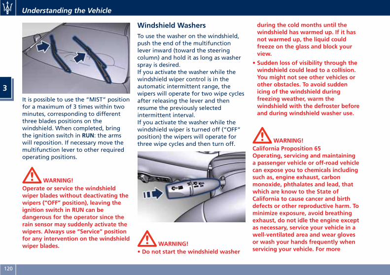
It is possible to use the “MIST” positionfor a maximum of 3 times within twominutes, corresponding to differentthree blades positions on thewindshield. When completed, bringthe ignition switch in RUN: the armswill reposition. If necessary move themultifunction lever to other requiredoperating positions.
WARNING!Operate or service the windshieldwiper blades without deactivating thewipers (“OFF” position), leaving theignition switch in RUN can bedangerous for the operator since therain sensor may suddenly activate thewipers. Always use “Service” positionfor any intervention on the windshieldwiper blades.
Windshield WashersTo use the washer on the windshield,push the end of the multifunctionlever inward (toward the steeringcolumn) and hold it as long as washerspray is desired.If you activate the washer while thewindshield wiper control is in theautomatic intermittent range, thewipers will operate for two wipe cyclesafter releasing the lever and thenresume the previously selectedintermittent interval.If you activate the washer while thewindshield wiper is turned off (“OFF”position) the wipers will operate forthree wipe cycles and then turn off.
WARNING!• Do not start the windshield washer
during the cold months until thewindshield has warmed up. If it hasnot warmed up, the liquid couldfreeze on the glass and block yourview.
• Sudden loss of visibility through thewindshield could lead to a collision.You might not see other vehicles orother obstacles. To avoid suddenicing of the windshield duringfreezing weather, warm thewindshield with the defroster beforeand during windshield washer use.
WARNING!California Proposition 65Operating, servicing and maintaininga passenger vehicle or off-road vehiclecan expose you to chemicals includingsuch as, engine exhaust, carbonmonoxide, phthalates and lead, thatwhich are know to the State ofCalifornia to cause cancer and birthdefects or other reproductive harm. Tominimize exposure, avoid breathingexhaust, do not idle the engine exceptas necessary, service your vehicle in awell-ventilated area and wear glovesor wash your hands frequently whenservicing your vehicle. For more
Understanding the Vehicle
3
120
information go to:www.P65Warnings.ca.gov/passenger-vehicle
Heated Windshield Washer Nozzles(for version/markets, where provided)
To avoid fluid freezing inside at lowexternal temperatures, the fluidsupply nozzles can be heated byinternal resistors.
Interior Features
Electric Power OutletsThe vehicle is equipped with four 12Volt (13 Amp) electric power outlets,two available for the front seatpassengers, one for rear seatpassengers and one fitted in the trunkcompartment.In vehicles equipped with “SmokingKit” the electric power outlet insidethe cupholder is replaced with acigarette lighter.All power outlets are supplied onlywhen the engine is started or theignition device set to ACC or RUN.Power outlets are protected by a fuse.Insert a cigar lighter or accessory pluginto the power outlets to ensureproper operation. Otherwise, checkthe matching fuse integrity, see “FuseReplacement” in section“Maintenance and Care” for furtherinformation.
CAUTION!
• Do not plug in accessories thatexceed the maximum power of 160Watts (13 Amps) at 12 Volts.
• Power outlets are designed foraccessory plugs only. Do not insert
any other object in the poweroutlets as this will damage the outletand blow the fuse. Damages causedby improper use of the power outletare not covered by the New VehicleLimited Warranty.
WARNING!To avoid serious injury or death:
• Only devices designed for use in thistype of outlet should be insertedinto any 12 Volt outlet.
• Replacing the fuses that protectpower outlets with others of higheramperage, there is the risk of fire.
• Do not touch with wet hands.
• Close the lids when the plug is notused and while driving the vehicle.
• If this outlet is mishandled, it maycause an electric shock and failure.
Power Outlet inside the Cupholder
To access the power outlet is inside thecupholder beside the transmissionlever, press the cover as indicated toopen it completely. This operation isnot necessary on versions withoutaccess cover. Remove the cigarette
Understanding the Vehicle
3
121
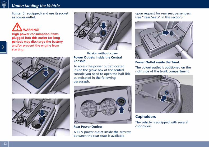
lighter (if equipped) and use its socketas power outlet.
WARNING!High power consumption itemsplugged into this outlet for longperiods may discharge the batteryand/or prevent the engine fromstarting.
Power Outlets inside the CentralConsole
To access the power outlet locatedinside the glove box of the centralconsole you need to open the half-lidsas indicated in the followingparagraph.
Rear Power Outlets
A 12 V power outlet inside the armrestbetween the rear seats is available
upon request for rear seat passengers(see “Rear Seats” in this section).
Power Outlet inside the Trunk
The power outlet is positioned on theright side of the trunk compartment.
CupholdersThe vehicle is equipped with severalcupholders.
Version without cover
Understanding the Vehicle
3
122
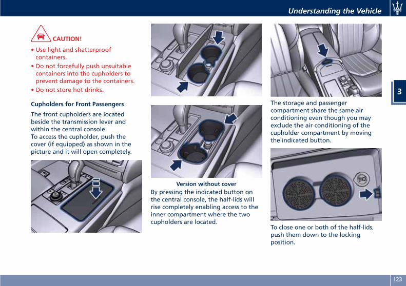
CAUTION!
• Use light and shatterproofcontainers.
• Do not forcefully push unsuitablecontainers into the cupholders toprevent damage to the containers.
• Do not store hot drinks.
Cupholders for Front Passengers
The front cupholders are locatedbeside the transmission lever andwithin the central console.To access the cupholder, push thecover (if equipped) as shown in thepicture and it will open completely.
By pressing the indicated button onthe central console, the half-lids willrise completely enabling access to theinner compartment where the twocupholders are located.
The storage and passengercompartment share the same airconditioning even though you mayexclude the air conditioning of thecupholder compartment by movingthe indicated button.
To close one or both of the half-lids,push them down to the lockingposition.
Version without cover
Understanding the Vehicle
3
123
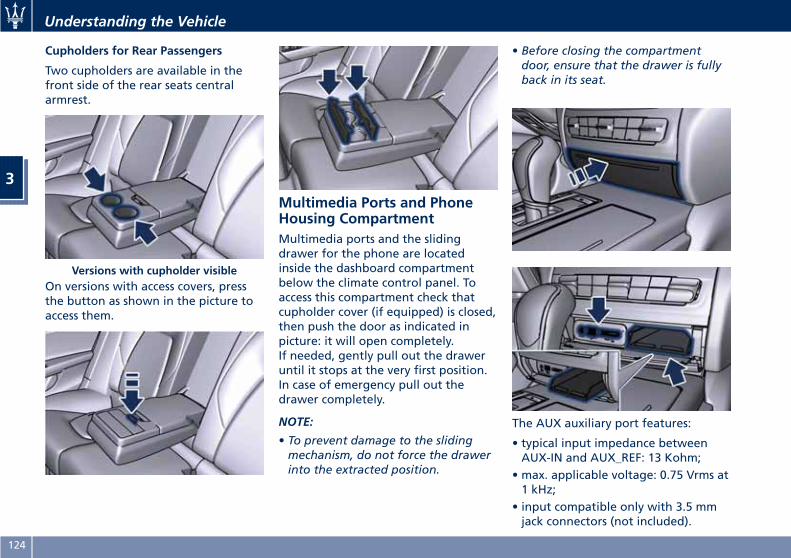
Cupholders for Rear Passengers
Two cupholders are available in thefront side of the rear seats centralarmrest.
On versions with access covers, pressthe button as shown in the picture toaccess them.
Multimedia Ports and PhoneHousing CompartmentMultimedia ports and the slidingdrawer for the phone are locatedinside the dashboard compartmentbelow the climate control panel. Toaccess this compartment check thatcupholder cover (if equipped) is closed,then push the door as indicated inpicture: it will open completely.If needed, gently pull out the draweruntil it stops at the very first position.In case of emergency pull out thedrawer completely.
NOTE:
• To prevent damage to the slidingmechanism, do not force the drawerinto the extracted position.
• Before closing the compartmentdoor, ensure that the drawer is fullyback in its seat.
The AUX auxiliary port features:
• typical input impedance betweenAUX-IN and AUX_REF: 13 Kohm;
• max. applicable voltage: 0.75 Vrms at1 kHz;
• input compatible only with 3.5 mmjack connectors (not included).
Versions with cupholder visible
Understanding the Vehicle
3
124
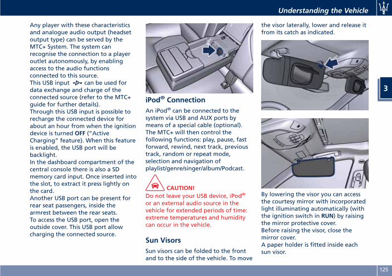
Any player with these characteristicsand analogue audio output (headsetoutput type) can be served by theMTC+ System. The system canrecognise the connection to a playeroutlet autonomously, by enablingaccess to the audio functionsconnected to this source.This USB input can be used fordata exchange and charge of theconnected source (refer to the MTC+guide for further details).Through this USB input is possible torecharge the connected device forabout an hour from when the ignitiondevice is turned OFF (“ActiveCharging” feature). When this featureis enabled, the USB port will bebacklight.In the dashboard compartment of thecentral console there is also a SDmemory card input. Once inserted intothe slot, to extract it press lightly onthe card.Another USB port can be present forrear seat passengers, inside thearmrest between the rear seats.To access the USB port, open theoutside cover. This USB port allowcharging the connected source.
iPod® ConnectionAn iPod® can be connected to thesystem via USB and AUX ports bymeans of a special cable (optional).The MTC+ will then control thefollowing functions: play, pause, fastforward, rewind, next track, previoustrack, random or repeat mode,selection and navigation ofplaylist/genre/singer/album/Podcast.
CAUTION!Do not leave your USB device, iPod®
or an external audio source in thevehicle for extended periods of time:extreme temperatures and humiditycan occur in the vehicle.
Sun VisorsSun visors can be folded to the frontand to the side of the vehicle. To move
the visor laterally, lower and release itfrom its catch as indicated.
By lowering the visor you can accessthe courtesy mirror with incorporatedlight illuminating automatically (withthe ignition switch in RUN) by raisingthe mirror protective cover.Before raising the visor, close themirror cover.A paper holder is fitted inside eachsun visor.
Understanding the Vehicle
3
125
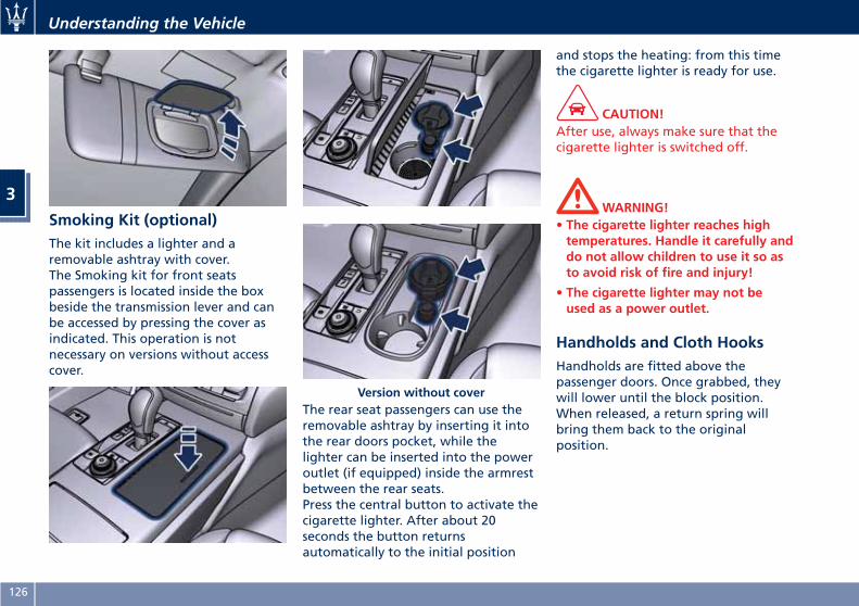
Smoking Kit (optional)The kit includes a lighter and aremovable ashtray with cover.The Smoking kit for front seatspassengers is located inside the boxbeside the transmission lever and canbe accessed by pressing the cover asindicated. This operation is notnecessary on versions without accesscover.
The rear seat passengers can use theremovable ashtray by inserting it intothe rear doors pocket, while thelighter can be inserted into the poweroutlet (if equipped) inside the armrestbetween the rear seats.Press the central button to activate thecigarette lighter. After about 20seconds the button returnsautomatically to the initial position
and stops the heating: from this timethe cigarette lighter is ready for use.
CAUTION!After use, always make sure that thecigarette lighter is switched off.
WARNING!• The cigarette lighter reaches hightemperatures. Handle it carefully anddo not allow children to use it so asto avoid risk of fire and injury!
• The cigarette lighter may not beused as a power outlet.
Handholds and Cloth HooksHandholds are fitted above thepassenger doors. Once grabbed, theywill lower until the block position.When released, a return spring willbring them back to the originalposition.
Version without cover
Understanding the Vehicle
3
126
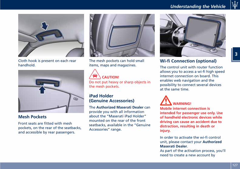
Cloth hook is present on each rearhandhold.
Mesh PocketsFront seats are fitted with meshpockets, on the rear of the seatbacks,and accessible by rear passengers.
The mesh pockets can hold smallitems, maps and magazines.
CAUTION!Do not put heavy or sharp objects inthe mesh pockets.
iPad Holder(Genuine Accessories)The Authorized Maserati Dealer canprovide you with all informationabout the “Maserati iPad Holder”mounted on the rear of the frontseatbacks, available in the “GenuineAccessories” range.
Wi-fi Connection (optional)The control unit with router functionallows you to access a wi-fi high speedinternet connection on board. Thisenables web navigation and thepossibility to connect several devicesat the same time.
WARNING!Mobile internet connection isintended for passenger use only. Useof handheld electronic devices whiledriving can cause an accident due todistraction, resulting in death orinjury.
In order to activate the wi-fi controlunit, please contact your AuthorizedMaserati Dealer.As part of the activation process, you’llneed to create a new account by
Understanding the Vehicle
3
127
accessing the following website of themanufacturer of the system thatMaserati has chosen for its models:https://signup.autonetmobile.com/.
CAUTION!Refer to an Authorized MaseratiDealer to activate the wi-fi controlunit.
Wi-fi connectivity range isapproximately 100 ft (30 m). In orderto avoid intrusions, the router issupplied with WEP or WPA2cryptography.During activation, to be performed byyour dealer, it is recommended toenable the security options availableby selecting the cryptographic version(WPA2 is recommended) and insertingthe password. In order to connect tothe wi-fi control unit, it will benecessary to insert this password oneach device you intend to use.After that, complete theauthentication process and enableWireless Security to avoid thatunauthorized users access the wi-fi. Tonavigate the internet it is nownecessary to pair the device you intendto use in the vehicle to the active wi-ficonnection; you can do that by
searching the available wirelessNetworks from the “Setting” menu.Select the wireless Network linked toyour vehicle and select “Connect” tostart the connection.If the auto-search is active for wirelessNetworks, every time the device willbe used inside the vehicle or close to it,it will connect to the set connection.
NOTE:• For futher information about thepairing procedure, refer to theinstructions given with your mobiledevice.
• For further information about wi-ficonnectivity and the control unit,please contact Client Service at1-800-977.2107 or write to:[email protected].
CAUTION!When selling the vehicle, you shouldcontact the above mentioned ClientService to have your device removedfrom the list of activated devicesregistered in your name. Do not simplygive your control unit password to anew owner. To avoid improperinternet access in your name and allownew owner registration you mustde-register with the service provider. A
new owner will not be able to registerthe device if it still appears registeredin the prior owner's name. If you are asubsequent owner, the unit could beimproperly monitored (usage andlocation), if it is still registered to aprior owner.
Understanding the Vehicle
3
128
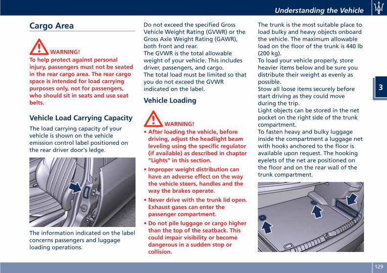
Cargo Area
WARNING!To help protect against personalinjury, passengers must not be seatedin the rear cargo area. The rear cargospace is intended for load carryingpurposes only, not for passengers,who should sit in seats and use seatbelts.
Vehicle Load Carrying CapacityThe load carrying capacity of yourvehicle is shown on the vehicleemission control label positioned onthe rear driver door's ledge.
The information indicated on the labelconcerns passengers and luggageloading operations.
Do not exceed the specified GrossVehicle Weight Rating (GVWR) or theGross Axle Weight Rating (GAWR),both front and rear.The GVWR is the total allowableweight of your vehicle. This includesdriver, passengers, and cargo.The total load must be limited so thatyou do not exceed the GVWRindicated on the label.
Vehicle Loading
WARNING!• After loading the vehicle, beforedriving, adjust the headlight beamleveling using the specific regulator(if available) as described in chapter“Lights” in this section.
• Improper weight distribution canhave an adverse effect on the waythe vehicle steers, handles and theway the brakes operate.
• Never drive with the trunk lid open.Exhaust gases can enter thepassenger compartment.
• Do not pile luggage or cargo higherthan the top of the seatback. Thiscould impair visibility or becomedangerous in a sudden stop orcollision.
The trunk is the most suitable place toload bulky and heavy objects onboardthe vehicle. The maximum allowableload on the floor of the trunk is 440 lb(200 kg).To load your vehicle properly, storeheavier items below and be sure youdistribute their weight as evenly aspossible.Stow all loose items securely beforestart driving as they could moveduring the trip.Light objects can be stored in the netpocket on the right side of the trunkcompartment.To fasten heavy and bulky luggageinside the compartment a luggage netwith hooks anchored to the floor isavailable upon request. The hookingeyelets of the net are positioned onthe floor and on the rear wall of thetrunk compartment.
Understanding the Vehicle
3
129
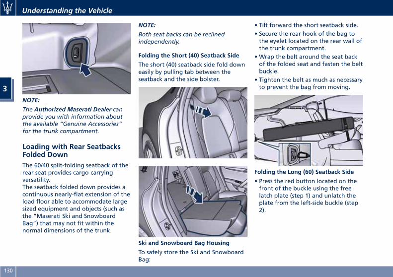
NOTE:
The Authorized Maserati Dealer canprovide you with information aboutthe available “Genuine Accessories”for the trunk compartment.
Loading with Rear SeatbacksFolded DownThe 60/40 split-folding seatback of therear seat provides cargo-carryingversatility.The seatback folded down provides acontinuous nearly-flat extension of theload floor able to accommodate largesized equipment and objects (such asthe “Maserati Ski and SnowboardBag”) that may not fit within thenormal dimensions of the trunk.
NOTE:
Both seat backs can be reclinedindependently.
Folding the Short (40) Seatback Side
The short (40) seatback side fold downeasily by pulling tab between theseatback and the side bolster.
Ski and Snowboard Bag Housing
To safely store the Ski and SnowboardBag:
• Tilt forward the short seatback side.• Secure the rear hook of the bag tothe eyelet located on the rear wall ofthe trunk compartment.
• Wrap the belt around the seat backof the folded seat and fasten the beltbuckle.
• Tighten the belt as much as necessaryto prevent the bag from moving.
Folding the Long (60) Seatback Side
• Press the red button located on thefront of the buckle using the freelatch plate (step 1) and unlatch theplate from the left-side buckle (step2).
Understanding the Vehicle
3
130
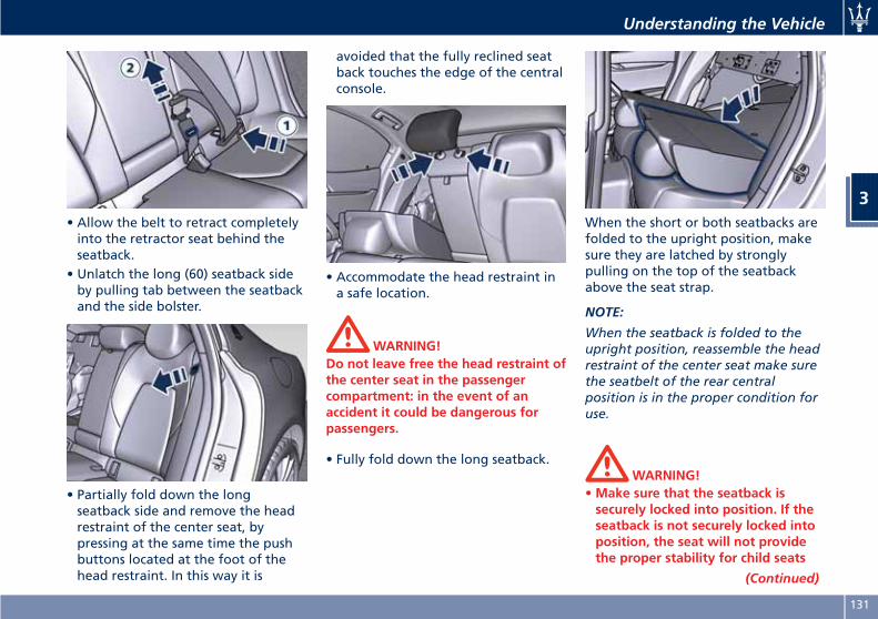
• Allow the belt to retract completelyinto the retractor seat behind theseatback.
• Unlatch the long (60) seatback sideby pulling tab between the seatbackand the side bolster.
• Partially fold down the longseatback side and remove the headrestraint of the center seat, bypressing at the same time the pushbuttons located at the foot of thehead restraint. In this way it is
avoided that the fully reclined seatback touches the edge of the centralconsole.
• Accommodate the head restraint ina safe location.
WARNING!Do not leave free the head restraint ofthe center seat in the passengercompartment: in the event of anaccident it could be dangerous forpassengers.
• Fully fold down the long seatback.
When the short or both seatbacks arefolded to the upright position, makesure they are latched by stronglypulling on the top of the seatbackabove the seat strap.
NOTE:
When the seatback is folded to theupright position, reassemble the headrestraint of the center seat make surethe seatbelt of the rear centralposition is in the proper condition foruse.
WARNING!•Make sure that the seatback issecurely locked into position. If theseatback is not securely locked intoposition, the seat will not providethe proper stability for child seats
(Continued)
Understanding the Vehicle
3
131
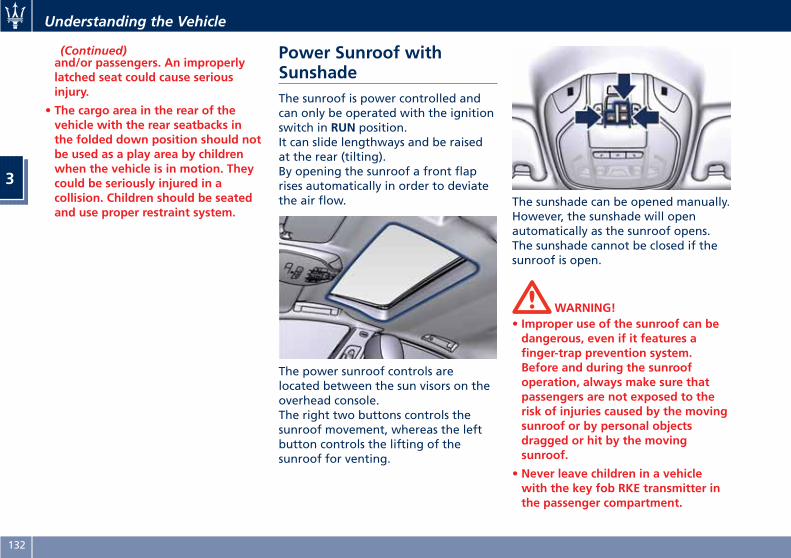
(Continued)and/or passengers. An improperlylatched seat could cause seriousinjury.
• The cargo area in the rear of thevehicle with the rear seatbacks inthe folded down position should notbe used as a play area by childrenwhen the vehicle is in motion. Theycould be seriously injured in acollision. Children should be seatedand use proper restraint system.
Power Sunroof withSunshadeThe sunroof is power controlled andcan only be operated with the ignitionswitch in RUN position.It can slide lengthways and be raisedat the rear (tilting).By opening the sunroof a front flaprises automatically in order to deviatethe air flow.
The power sunroof controls arelocated between the sun visors on theoverhead console.The right two buttons controls thesunroof movement, whereas the leftbutton controls the lifting of thesunroof for venting.
The sunshade can be opened manually.However, the sunshade will openautomatically as the sunroof opens.The sunshade cannot be closed if thesunroof is open.
WARNING!• Improper use of the sunroof can bedangerous, even if it features afinger-trap prevention system.Before and during the sunroofoperation, always make sure thatpassengers are not exposed to therisk of injuries caused by the movingsunroof or by personal objectsdragged or hit by the movingsunroof.
• Never leave children in a vehiclewith the key fob RKE transmitter inthe passenger compartment.
Understanding the Vehicle
3
132
• In a collision, there is a greater riskof being thrown from the vehicle ifthe sunroof is open. Always fastenyour seat belt properly and makesure all passengers are properlysecured too.
• Do not allow small children tooperate the sunroof. Never insertfingers, other body parts, or anyobject through the roof opening.
CAUTION!
• In the event of rain, always close thesunroof to prevent waterinfiltrations from staining thefabric/leather upholstery.
• Do not open the sunroof if there isice on it: risk of damage.
Slide Opening Sunroof• Full automatic express openingPress the right rear button for morethan half second and the sunroofwill open automatically regardlessof any previous position. Thesunroof will open fully and stopautomatically. During thisoperation, if any sunroof button ispressed, the sunroof will stop.
• Full or partial manual openingTo open the sunroof manually pressthe right rear button for less thanhalf second to move step by stepthe sunroof panel.
Venting SunroofPress and release the left button, andthe sunroof will open to the ventposition. This is called “Express Vent”,and will occur regardless of sunroofposition. During this openingoperation, any movement of thebutton will stop the sunroof.
Pinch Protect FeatureThis feature will detect an obstructionin the opening of the sunroof duringexpress close operation. If anobstruction is detected, the sunroofwill automatically retract. If thisoccurs, remove the obstruction thenpress the right front button andrelease to express close.
NOTE:
If three consecutive attempts to closein express mode the sunroof result inpinch protect reversals, the fourthattempt will be manual, with pinchprotect feature disabled.
Pinch Protect Override
If any obstruction (ice, debris, etc.)prevents closing the sunroof, press theright front button and hold for twoseconds after the reversal occurs. Thisallows the sunroof to move towardthe closed position.
NOTE:
Pinch protection is disabled whilepressing the right front button.
Wind BuffetingWind buffeting can be described asthe perception of pressure or ahelicopter-type sound. Your vehiclemay exhibit wind buffeting with thewindows down, or the sunroof incertain open or partially openpositions. This is a normal occurrenceand can be minimised. If the buffetingoccurs with the rear windows open,then open the front and rear windowstogether to minimise the buffeting. Ifthe buffeting occurs with the sunroofopen, then adjust the sunroof openingto minimise the buffeting.
Ignition Off OperationThe power sunroof controls willremain active for up to approximatelyten minutes after the ignition switch is
Understanding the Vehicle
3
133
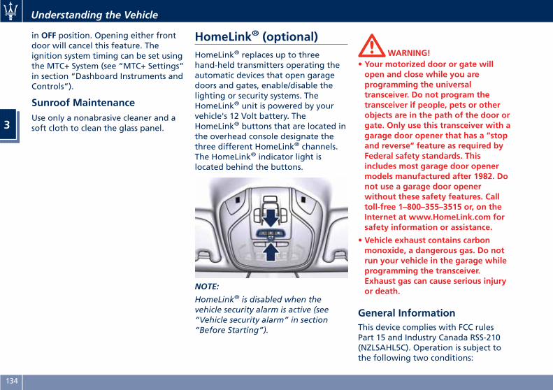
in OFF position. Opening either frontdoor will cancel this feature. Theignition system timing can be set usingthe MTC+ System (see “MTC+ Settings”in section “Dashboard Instruments andControls”).
Sunroof MaintenanceUse only a nonabrasive cleaner and asoft cloth to clean the glass panel.
HomeLink® (optional)HomeLink® replaces up to threehand-held transmitters operating theautomatic devices that open garagedoors and gates, enable/disable thelighting or security systems. TheHomeLink® unit is powered by yourvehicle's 12 Volt battery. TheHomeLink® buttons that are located inthe overhead console designate thethree different HomeLink® channels.The HomeLink® indicator light islocated behind the buttons.
NOTE:
HomeLink® is disabled when thevehicle security alarm is active (see“Vehicle security alarm” in section“Before Starting”).
WARNING!• Your motorized door or gate willopen and close while you areprogramming the universaltransceiver. Do not program thetransceiver if people, pets or otherobjects are in the path of the door orgate. Only use this transceiver with agarage door opener that has a “stopand reverse” feature as required byFederal safety standards. Thisincludes most garage door openermodels manufactured after 1982. Donot use a garage door openerwithout these safety features. Calltoll-free 1–800–355–3515 or, on theInternet at www.HomeLink.com forsafety information or assistance.
• Vehicle exhaust contains carbonmonoxide, a dangerous gas. Do notrun your vehicle in the garage whileprogramming the transceiver.Exhaust gas can cause serious injuryor death.
General InformationThis device complies with FCC rulesPart 15 and Industry Canada RSS-210(NZLSAHL5C). Operation is subject tothe following two conditions:
Understanding the Vehicle
3
134
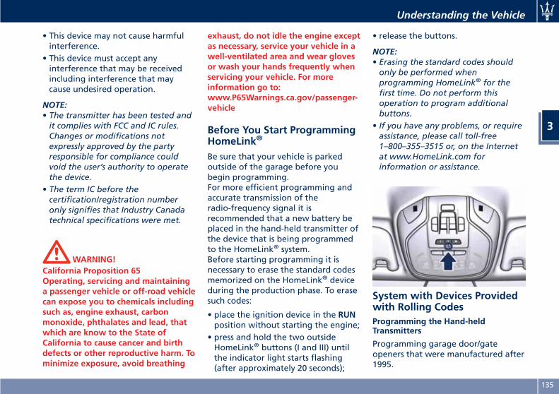
• This device may not cause harmfulinterference.
• This device must accept anyinterference that may be receivedincluding interference that maycause undesired operation.
NOTE:• The transmitter has been tested andit complies with FCC and IC rules.Changes or modifications notexpressly approved by the partyresponsible for compliance couldvoid the user’s authority to operatethe device.
• The term IC before thecertification/registration numberonly signifies that Industry Canadatechnical specifications were met.
WARNING!California Proposition 65Operating, servicing and maintaininga passenger vehicle or off-road vehiclecan expose you to chemicals includingsuch as, engine exhaust, carbonmonoxide, phthalates and lead, thatwhich are know to the State ofCalifornia to cause cancer and birthdefects or other reproductive harm. Tominimize exposure, avoid breathing
exhaust, do not idle the engine exceptas necessary, service your vehicle in awell-ventilated area and wear glovesor wash your hands frequently whenservicing your vehicle. For moreinformation go to:www.P65Warnings.ca.gov/passenger-vehicle
Before You Start ProgrammingHomeLink®
Be sure that your vehicle is parkedoutside of the garage before youbegin programming.For more efficient programming andaccurate transmission of theradio-frequency signal it isrecommended that a new battery beplaced in the hand-held transmitter ofthe device that is being programmedto the HomeLink® system.Before starting programming it isnecessary to erase the standard codesmemorized on the HomeLink® deviceduring the production phase. To erasesuch codes:
• place the ignition device in the RUNposition without starting the engine;
• press and hold the two outsideHomeLink® buttons (I and III) untilthe indicator light starts flashing(after approximately 20 seconds);
• release the buttons.
NOTE:• Erasing the standard codes shouldonly be performed whenprogramming HomeLink® for thefirst time. Do not perform thisoperation to program additionalbuttons.
• If you have any problems, or requireassistance, please call toll-free1–800–355–3515 or, on the Internetat www.HomeLink.com forinformation or assistance.
System with Devices Providedwith Rolling CodesProgramming the Hand-heldTransmitters
Programming garage door/gateopeners that were manufactured after1995.
Understanding the Vehicle
3
135
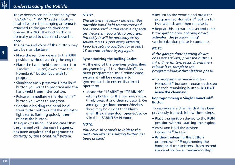
These devices can be identified by the“LEARN” or “TRAIN” setting buttonlocated where the hanging antenna isattached to the garage door/gateopener. It is NOT the button that isnormally used to open and close thedoor.The name and color of the button mayvary by manufacturer.
• Place the ignition device to the RUNposition without starting the engine.
• Place the hand-held transmitter 1 to3 inches (5 - 30 cm) away from theHomeLink® button you wish toprogram.
• Simultaneously press the Homelink®
button you want to program and thehand-held transmitter button.
• Release immediately the Homelink®
button you want to program.• Continue holding the hand-heldtransmitter button until the indicatorlight starts flashing quickly; thenrelease the button.
The quick flashing light indicates thatthe channel with the new frequencyhas been acquired and programmedcorrectly by the HomeLink® system.
NOTE:
The distance necessary between theportable hand-held transmitter andthe HomeLink® in the vehicle dependson the system you wish to program.Probably it will be necessary to tryseveral times. Upon every attempt,keep the setting position for at least15 seconds before trying again.
Synchronizing the Rolling Codes
At the end of the previously-describedprogramming, if the HomeLink® hasbeen programmed for a rolling codesystem, it will be necessary tosynchronize it to ensure its correctoperation.
• Locate the “LEARN” or “TRAINING”setting button of the opening motor.Firmly press it and then release it. Onsome garage door openers/devicesthere may be a light that blinkswhen the garage door opener/deviceis in the LEARN/TRAIN mode.
NOTE:
You have 30 seconds to initiate thenext step after the setting button hasbeen pressed.
• Return to the vehicle and press theprogrammed HomeLink® button fortwo seconds and then release it.
• Repeat this operation a second time.If the garage door opening deviceactivates, the programming/synchronization phase is complete.
NOTE:
If the garage door opening devicedoes not activate, press the button athird time for two seconds and thenrelease it to complete theprogramming/synchronization phase.
• To program the remaining twoHomeLink® buttons, repeat each stepfor each remaining button. DO NOTerase the channels.
Reprogramming a Single HomeLink®
Button
To reprogram a channel that has beenpreviously trained, follow these steps:
• Place the ignition device to the RUNposition without starting the engine.
• Press and hold the desiredHomeLink® button.
•Without releasing the buttonproceed with “Programming thehand-held transmitters” from secondstep and follow all remaining steps.
Understanding the Vehicle
3
136
System with Devices WithoutRolling CodeProgramming the Hand-heldTransmitters
Programming garage door openersmanufactured before 1995.
• Turn the ignition device to the RUNposition without starting the engine.
• Place the hand-held transmitter 1 to3 inches (5 to 30 cm) away from theHomeLink® button you wish toprogram.
• Simultaneously press and hold bothbuttons until the indicator lightstarts flashing quickly; then releaseboth buttons.
The quick flashing light indicates thatthe channel with the new frequencyhas been acquired and programmedcorrectly by the HomeLink® system.
NOTE:
The distance necessary between theportable hand-held transmitter andthe HomeLink® in the vehicle dependson the system you wish to program.Probably it will be necessary to tryseveral times. Upon every attempt,keep the setting position for at least15 seconds before trying again.
• Press and hold the programmedHomeLink® button.
If the garage door opener/deviceactivates, programming is complete.To program the remaining twoHomeLink® buttons, repeat each stepfor each remaining button. Do noterase the channels.
Reprogramming a Single HomeLink®
Button
To reprogram a channel that has beenpreviously trained, follow these steps:
• Place the ignition device to the RUNposition without starting the engine.
• Press and hold the desiredHomeLink® button.
•Without releasing the buttonproceed with “Programming thehand-held transmitters” from secondstep and follow all remaining steps.
Using HomeLink®
To operate, press and release theprogrammed HomeLink® button.Activation will now occur for theprogrammed device (i.e., garage dooropener, gate operator, security system,entry door lock, home/office lighting,etc.). The hand-held transmitter of thedevice may also be used at any time.
SecurityIt is advisable to erase all channelsbefore you sell or turn in your vehicle.To erase the channels press and holdthe two outside HomeLink® buttons (Iand III) until the indicator light startsflashing (after approximately 20seconds).The HomeLink® Universal Transceiveris disabled when the vehicle securityalarm is active (see “Vehicle securityalarm” in section “Before Starting”).
Troubleshooting TipsIf you are having trouble whileprogramming HomeLink®, here aresome of the most common solutions:
• Replace the battery in the originalhand-held transmitter.
• Press the LEARN button on thegarage door opener to complete thetraining for a rolling code.
• Did you unplug the device forprogramming and forgot to plug itback in?
If you have any problems, or requireassistance, please call toll-free1–800–355–3515 or, on the Internet atwww.HomeLink.com for informationor assistance.
Understanding the Vehicle
3
137
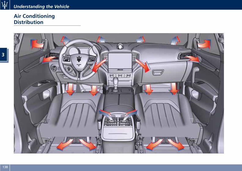
Air ConditioningDistribution
Understanding the Vehicle
3
138
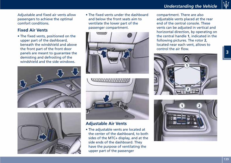
Adjustable and fixed air vents allowpassengers to achieve the optimalcomfort conditions.
Fixed Air Vents• The fixed vents, positioned on theupper part of the dashboard,beneath the windshield and abovethe front part of the front doorpanels are meant to guarantee thedemisting and defrosting of thewindshield and the side windows.
• The fixed vents under the dashboardand below the front seats aim toventilate the lower part of thepassenger compartment.
Adjustable Air Vents• The adjustable vents are located atthe center of the dashboard, to bothsides of the MTC+ display, and at theside ends of the dashboard. Theyhave the purpose of ventilating theupper part of the passenger
compartment. There are alsoadjustable vents placed at the rearend of the central console. Thesevents can be adjusted in vertical andhorizontal direction, by operating onthe central handle 1, indicated in thefollowing pictures. The rotor 2,located near each vent, allows tocontrol the air flow.
Understanding the Vehicle
3
139
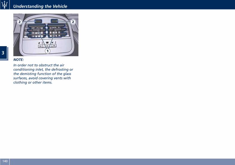
NOTE:
In order not to obstruct the airconditioning inlet, the defrosting orthe demisting function of the glasssurfaces, avoid covering vents withclothing or other items.
Understanding the Vehicle
3
140
4 – Dashboard Instruments and Controls
Instrument Cluster . . . . . . . . . . . . . . . . . . . . . . . . . . . . . . . . . . . . . . 142Infotainment System . . . . . . . . . . . . . . . . . . . . . . . . . . . . . . . . . . . . 165Audio Controls . . . . . . . . . . . . . . . . . . . . . . . . . . . . . . . . . . . . . . . . . 172Audio System . . . . . . . . . . . . . . . . . . . . . . . . . . . . . . . . . . . . . . . . . . 173MTC+ “Controls” Screen . . . . . . . . . . . . . . . . . . . . . . . . . . . . . . . . . 174MTC+ Settings . . . . . . . . . . . . . . . . . . . . . . . . . . . . . . . . . . . . . . . . . 178Dashboard Compartment . . . . . . . . . . . . . . . . . . . . . . . . . . . . . . . . 189Analog Clock . . . . . . . . . . . . . . . . . . . . . . . . . . . . . . . . . . . . . . . . . . 192Air Conditioning Controls . . . . . . . . . . . . . . . . . . . . . . . . . . . . . . . . 193Phone and Voice Controls on Steering Wheel . . . . . . . . . . . . . . . . . 199
141
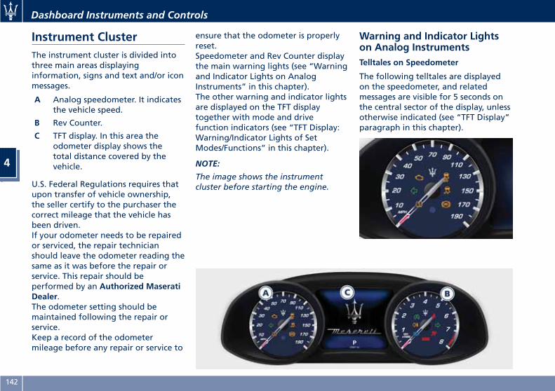
Instrument ClusterThe instrument cluster is divided intothree main areas displayinginformation, signs and text and/or iconmessages.
A Analog speedometer. It indicatesthe vehicle speed.
B Rev Counter.
C TFT display. In this area theodometer display shows thetotal distance covered by thevehicle.
U.S. Federal Regulations requires thatupon transfer of vehicle ownership,the seller certify to the purchaser thecorrect mileage that the vehicle hasbeen driven.If your odometer needs to be repairedor serviced, the repair technicianshould leave the odometer reading thesame as it was before the repair orservice. This repair should beperformed by an Authorized MaseratiDealer.The odometer setting should bemaintained following the repair orservice.Keep a record of the odometermileage before any repair or service to
ensure that the odometer is properlyreset.Speedometer and Rev Counter displaythe main warning lights (see “Warningand Indicator Lights on AnalogInstruments” in this chapter).The other warning and indicator lightsare displayed on the TFT displaytogether with mode and drivefunction indicators (see “TFT Display:Warning/Indicator Lights of SetModes/Functions” in this chapter).
NOTE:
The image shows the instrumentcluster before starting the engine.
Warning and Indicator Lightson Analog InstrumentsTelltales on Speedometer
The following telltales are displayedon the speedometer, and relatedmessages are visible for 5 seconds onthe central sector of the display, unlessotherwise indicated (see “TFT Display”paragraph in this chapter).
Dashboard Instruments and Controls
4
142
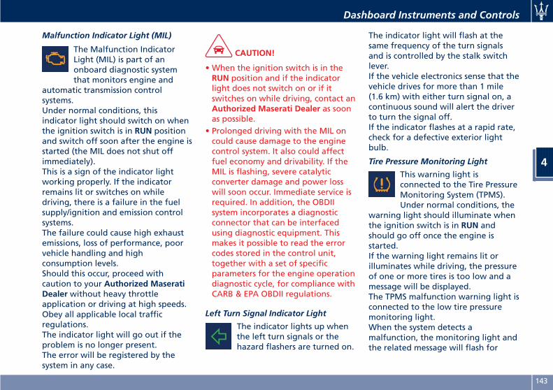
Malfunction Indicator Light (MIL)
The Malfunction IndicatorLight (MIL) is part of anonboard diagnostic systemthat monitors engine and
automatic transmission controlsystems.Under normal conditions, thisindicator light should switch on whenthe ignition switch is in RUN positionand switch off soon after the engine isstarted (the MIL does not shut offimmediately).This is a sign of the indicator lightworking properly. If the indicatorremains lit or switches on whiledriving, there is a failure in the fuelsupply/ignition and emission controlsystems.The failure could cause high exhaustemissions, loss of performance, poorvehicle handling and highconsumption levels.Should this occur, proceed withcaution to your Authorized MaseratiDealer without heavy throttleapplication or driving at high speeds.Obey all applicable local trafficregulations.The indicator light will go out if theproblem is no longer present.The error will be registered by thesystem in any case.
CAUTION!
• When the ignition switch is in theRUN position and if the indicatorlight does not switch on or if itswitches on while driving, contact anAuthorized Maserati Dealer as soonas possible.
• Prolonged driving with the MIL oncould cause damage to the enginecontrol system. It also could affectfuel economy and drivability. If theMIL is flashing, severe catalyticconverter damage and power losswill soon occur. Immediate service isrequired. In addition, the OBDIIsystem incorporates a diagnosticconnector that can be interfacedusing diagnostic equipment. Thismakes it possible to read the errorcodes stored in the control unit,together with a set of specificparameters for the engine operationdiagnostic cycle, for compliance withCARB & EPA OBDII regulations.
Left Turn Signal Indicator Light
The indicator lights up whenthe left turn signals or thehazard flashers are turned on.
The indicator light will flash at thesame frequency of the turn signalsand is controlled by the stalk switchlever.If the vehicle electronics sense that thevehicle drives for more than 1 mile(1.6 km) with either turn signal on, acontinuous sound will alert the driverto turn the signal off.If the indicator flashes at a rapid rate,check for a defective exterior lightbulb.
Tire Pressure Monitoring Light
This warning light isconnected to the Tire PressureMonitoring System (TPMS).Under normal conditions, the
warning light should illuminate whenthe ignition switch is in RUN andshould go off once the engine isstarted.If the warning light remains lit orilluminates while driving, the pressureof one or more tires is too low and amessage will be displayed.The TPMS malfunction warning light isconnected to the low tire pressuremonitoring light.When the system detects amalfunction, the monitoring light andthe related message will flash for
Dashboard Instruments and Controls
4
143
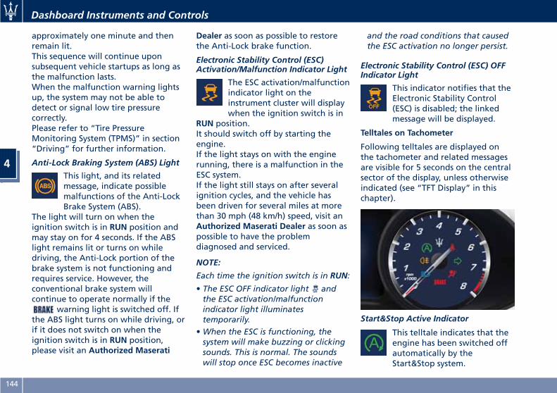
approximately one minute and thenremain lit.This sequence will continue uponsubsequent vehicle startups as long asthe malfunction lasts.When the malfunction warning lightsup, the system may not be able todetect or signal low tire pressurecorrectly.Please refer to “Tire PressureMonitoring System (TPMS)” in section“Driving” for further information.
Anti-Lock Braking System (ABS) Light
This light, and its relatedmessage, indicate possiblemalfunctions of the Anti-LockBrake System (ABS).
The light will turn on when theignition switch is in RUN position andmay stay on for 4 seconds. If the ABSlight remains lit or turns on whiledriving, the Anti-Lock portion of thebrake system is not functioning andrequires service. However, theconventional brake system willcontinue to operate normally if the
warning light is switched off. Ifthe ABS light turns on while driving, orif it does not switch on when theignition switch is in RUN position,please visit an Authorized Maserati
Dealer as soon as possible to restorethe Anti-Lock brake function.
Electronic Stability Control (ESC)Activation/Malfunction Indicator Light
The ESC activation/malfunctionindicator light on theinstrument cluster will displaywhen the ignition switch is in
RUN position.It should switch off by starting theengine.If the light stays on with the enginerunning, there is a malfunction in theESC system.If the light still stays on after severalignition cycles, and the vehicle hasbeen driven for several miles at morethan 30 mph (48 km/h) speed, visit anAuthorized Maserati Dealer as soon aspossible to have the problemdiagnosed and serviced.
NOTE:
Each time the ignition switch is in RUN:
• The ESC OFF indicator light andthe ESC activation/malfunctionindicator light illuminatestemporarily.
•When the ESC is functioning, thesystem will make buzzing or clickingsounds. This is normal. The soundswill stop once ESC becomes inactive
and the road conditions that causedthe ESC activation no longer persist.
Electronic Stability Control (ESC) OFFIndicator Light
This indicator notifies that theElectronic Stability Control(ESC) is disabled; the linkedmessage will be displayed.
Telltales on Tachometer
Following telltales are displayed onthe tachometer and related messagesare visible for 5 seconds on the centralsector of the display, unless otherwiseindicated (see “TFT Display” in thischapter).
Start&Stop Active Indicator
This telltale indicates that theengine has been switched offautomatically by theStart&Stop system.
Dashboard Instruments and Controls
4
144
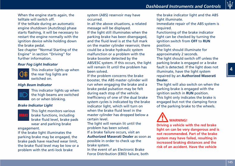
When the engine starts again, thetelltale will switch off.If the telltale during an automaticengine shutdown (AutoStop) phasestarts flashing, it will be necessary torestart the engine normally with theignition device while holding downthe brake pedal.See chapter “Normal Starting of theEngine” in section “Driving” forfurther information.
Rear Fog Light Indicator
This indicator lights up whenthe rear fog lights areswitched on.
High Beam Indicator
This indicator lights up whenthe high beams are switchedon or when blinking.
Brake Indicator Light
This light monitors variousbrake functions, includingbrake fluid level, brake padswear and parking brake
engagement.If the brake light illuminates theparking brake may be engaged, thebrake pads have reached wear limit,the brake fluid level may be low or aproblem with the anti-lock brake
system (ABS) reservoir may haveoccurred.In all the above situations, a relatedmessage will be displayed.If the light still illuminates when theparking brake has been disengaged,and the fluid level is at the full markon the master cylinder reservoir, therecould be a brake hydraulic systemmalfunction or a problem with thebrake booster detected by theABS/ESC system. If this occurs, the lightwill remain lit until the problem hasbeen solved.If the problem concerns the brakebooster, the ABS master cylinder willrun when engaging the brake and abrake pedal pulsation may be feltduring each stop of the vehicle.Inefficiency of one of the dual brakesystem cycles is indicated by the brakeindicator light, which will turn onwhen the brake fluid level in themaster cylinder has dropped below acertain level.The light will remain lit until theproblem has been solved.If a brake failure occurs, visit anAuthorized Maserati Dealer as soon aspossible in order to check up thebrake system.In the event of an Electronic BrakeForce Distribution (EBD) failure, both
the brake indicator light and the ABSlight illuminate.Immediate repair of the ABS system isrequired.Functioning of the brake indicatorlight can be checked by turning theignition switch from OFF to RUNposition.The light should illuminate forapproximately 2 seconds.The light should switch off unless theparking brake is engaged or a brakefault is detected. If the light does notilluminate, have the light systemrepaired by an Authorized MaseratiDealer.The light will also switch on when theparking brake is engaged with theignition switch in RUN position.This light only indicates the brake isengaged but not the clamping forceof the parking brake to the wheels.
WARNING!Driving a vehicle with the red brakelight on can be very dangerous and isnot recommended. Part of the brakesystem may have failed, resulting inincreased braking distances and therisk of an accident. Have the vehicle
Dashboard Instruments and Controls
4
145
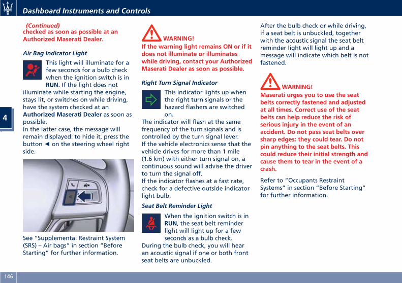
(Continued)checked as soon as possible at anAuthorized Maserati Dealer.
Air Bag Indicator Light
This light will illuminate for afew seconds for a bulb checkwhen the ignition switch is inRUN. If the light does not
illuminate while starting the engine,stays lit, or switches on while driving,have the system checked at anAuthorized Maserati Dealer as soon aspossible.In the latter case, the message willremain displayed: to hide it, press thebutton◄ on the steering wheel rightside.
See “Supplemental Restraint System(SRS) – Air bags” in section “BeforeStarting” for further information.
WARNING!If the warning light remains ON or if itdoes not illuminate or illuminateswhile driving, contact your AuthorizedMaserati Dealer as soon as possible.
Right Turn Signal Indicator
This indicator lights up whenthe right turn signals or thehazard flashers are switchedon.
The indicator will flash at the samefrequency of the turn signals and iscontrolled by the turn signal lever.If the vehicle electronics sense that thevehicle drives for more than 1 mile(1.6 km) with either turn signal on, acontinuous sound will advise the driverto turn the signal off.If the indicator flashes at a fast rate,check for a defective outside indicatorlight bulb.
Seat Belt Reminder Light
When the ignition switch is inRUN, the seat belt reminderlight will light up for a fewseconds as a bulb check.
During the bulb check, you will hearan acoustic signal if one or both frontseat belts are unbuckled.
After the bulb check or while driving,if a seat belt is unbuckled, togetherwith the acoustic signal the seat beltreminder light will light up and amessage will indicate which belt is notfastened.
WARNING!Maserati urges you to use the seatbelts correctly fastened and adjustedat all times. Correct use of the seatbelts can help reduce the risk ofserious injury in the event of anaccident. Do not pass seat belts oversharp edges: they could tear. Do notpin anything to the seat belts. Thiscould reduce their initial strength andcause them to tear in the event of acrash.
Refer to “Occupants RestraintSystems” in section “Before Starting”for further information.
Dashboard Instruments and Controls
4
146
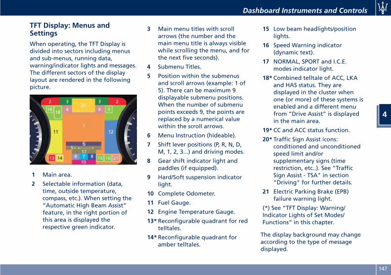
TFT Display: Menus andSettingsWhen operating, the TFT Display isdivided into sectors including menusand sub-menus, running data,warning/indicator lights and messages.The different sectors of the displaylayout are rendered in the followingpicture.
1 Main area.
2 Selectable information (data,time, outside temperature,compass, etc.). When setting the“Automatic High Beam Assist”feature, in the right portion ofthis area is displayed therespective green indicator.
3 Main menu titles with scrollarrows (the number and themain menu title is always visiblewhile scrolling the menu, and forthe next five seconds).
4 Submenu Titles.
5 Position within the submenusand scroll arrows (example: 1 of5). There can be maximum 9displayable submenu positions.When the number of submenupoints exceeds 9, the points arereplaced by a numerical valuewithin the scroll arrows.
6 Menu Instruction (hideable).
7 Shift lever positions (P, R, N, D,M, 1, 2, 3...) and driving modes.
8 Gear shift indicator light andpaddles (if equipped).
9 Hard/Soft suspension indicatorlight.
10 Complete Odometer.
11 Fuel Gauge.
12 Engine Temperature Gauge.
13*Reconfigurable quadrant for redtelltales.
14*Reconfigurable quadrant foramber telltales.
15 Low beam headlights/positionlights.
16 Speed Warning indicator(dynamic text).
17 NORMAL, SPORT and I.C.E.modes indicator light.
18*Combined telltale of ACC, LKAand HAS status. They aredisplayed in the cluster whenone (or more) of these systems isenabled and a different menufrom “Drive Assist” is displayedin the main area.
19*CC and ACC status function.
20* Traffic Sign Assist icons:conditioned and unconditionedspeed limit and/orsupplementary signs (timerestriction, etc..). See "TrafficSign Assist - TSA" in section"Driving" for further details.
21 Electric Parking Brake (EPB)failure warning light.
(*) See “TFT Display: Warning/Indicator Lights of Set Modes/Functions” in this chapter.
The display background may changeaccording to the type of messagedisplayed.
Dashboard Instruments and Controls
4
147
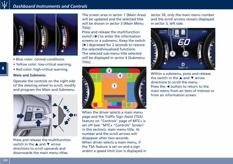
• Blue color: normal conditions.• Yellow color: low-critical warning.• Red color: high-critical warning.
Main and Submenu
Operate the controls on the right sideof the steering wheel to scroll, modifyand program the Main and Submenu.
Press and release the multifunctionswitch in the ▲ and▼ arrowdirections to scroll upwards anddownwards the main menu titles.
The screen area in sector 1 (Main Area)will be updated and the selected titlewill be shown in sector 3 (Main MenuTitle).Press and release the multifunctionswitch (►) to enter the informationscreens or a submenu. Keep the switch(►) depressed for 2 seconds to restorethe selected/visualized functions.The selected sub-menu title selectedwill be displayed in sector 4 (SubmenuTitle).
When the driver selects a main menupage and the Traffic Sign Assist (TSA)feature on "Controls" page of MTC+ isset off (see "MTC+ "Controls" Screen"in this section), main menu title, itsnumber and the scroll arrows willdisappear after two seconds.When driver selects a main menu, ifthe TSA feature is set on and a signand/or a speed limit icon is displayed in
sector 20, only the main menu numberand the scroll arrows remain displayedin sector 3, left side.
Within a submenu, press and releasethe switch in the ▲ and▼ arrowdirections to scroll the menu.Press the◄ button to return to themain menu from an item of interest orfrom an information screen.
Dashboard Instruments and Controls
4
148
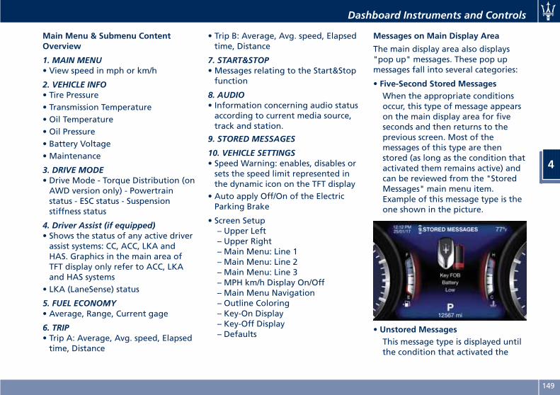
Main Menu & Submenu ContentOverview
1. MAIN MENU• View speed in mph or km/h
2. VEHICLE INFO• Tire Pressure• Transmission Temperature• Oil Temperature• Oil Pressure• Battery Voltage• Maintenance
3. DRIVE MODE• Drive Mode - Torque Distribution (onAWD version only) - Powertrainstatus - ESC status - Suspensionstiffness status
4. Driver Assist (if equipped)• Shows the status of any active driverassist systems: CC, ACC, LKA andHAS. Graphics in the main area ofTFT display only refer to ACC, LKAand HAS systems
• LKA (LaneSense) status
5. FUEL ECONOMY• Average, Range, Current gage
6. TRIP• Trip A: Average, Avg. speed, Elapsedtime, Distance
• Trip B: Average, Avg. speed, Elapsedtime, Distance
7. START&STOP• Messages relating to the Start&Stopfunction
8. AUDIO• Information concerning audio statusaccording to current media source,track and station.
9. STORED MESSAGES
10. VEHICLE SETTINGS• Speed Warning: enables, disables orsets the speed limit represented inthe dynamic icon on the TFT display
• Auto apply Off/On of the ElectricParking Brake
• Screen Setup– Upper Left– Upper Right– Main Menu: Line 1– Main Menu: Line 2– Main Menu: Line 3– MPH km/h Display On/Off– Main Menu Navigation– Outline Coloring– Key-On Display– Key-Off Display– Defaults
Messages on Main Display Area
The main display area also displays"pop up" messages. These pop upmessages fall into several categories:
• Five-Second Stored MessagesWhen the appropriate conditionsoccur, this type of message appearson the main display area for fiveseconds and then returns to theprevious screen. Most of themessages of this type are thenstored (as long as the condition thatactivated them remains active) andcan be reviewed from the "StoredMessages" main menu item.Example of this message type is theone shown in the picture.
• Unstored MessagesThis message type is displayed untilthe condition that activated the
Dashboard Instruments and Controls
4
149
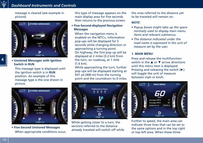
message is cleared (see example inpicture).
• Unstored Messages with IgnitionSwitch in RUNThis message type is displayed untilthe ignition switch is in RUNposition. An example of thismessage type is the one shown inpicture.
• Five-Second Unstored MessagesWhen appropriate conditions occur,
this type of message appears on themain display area for five secondsthen returns to the previous screen.
• Five-Second-displayed NavigationMessagesWhen the navigation menu isenabled on the MTC+, informationpop-ups will be displayed for 5seconds while changing direction orapproaching a turning point.On highway, the first pop up will bedisplayed at 2 miles (3.2 km) fromthe turn, on roadway, at 1 mile(1.6 km).While approaching the turn, furtherpop ups will be displayed starting at437 yd (400 m) from the turningpoint and the countdown to 0 miles.
While getting closer to a turn, thesections referred to the distancealready traveled will switch off while
the ones referred to the distance yetto be traveled will remain on.
NOTE:
• Popup boxes might take up the spacenormally used to display main menuitems and relevant submenus.
• The distance indicated under theroad name is expressed in the unit ofmeasure set by the user.
1. MAIN MENU
Press and release the multifunctionswitch in the ▲ or▼ arrow directionsuntil this menu item is displayed.Pressing and releasing the switch (►)will toggle the unit of measurebetween mph or km/h.
Further to speed, the main area canindicate three lines that can be set tothe same options and in the top rightor top left area. When these three
Dashboard Instruments and Controls
4
150
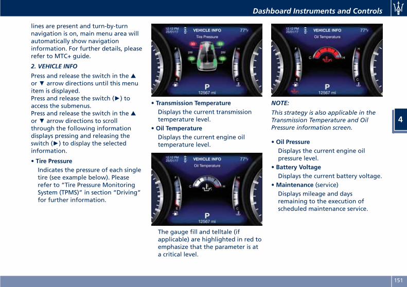
lines are present and turn-by-turnnavigation is on, main menu area willautomatically show navigationinformation. For further details, pleaserefer to MTC+ guide.
2. VEHICLE INFO
Press and release the switch in the ▲or▼ arrow directions until this menuitem is displayed.Press and release the switch (►) toaccess the submenus.Press and release the switch in the ▲or▼ arrow directions to scrollthrough the following informationdisplays pressing and releasing theswitch (►) to display the selectedinformation.
• Tire PressureIndicates the pressure of each singletire (see example below). Pleaserefer to “Tire Pressure MonitoringSystem (TPMS)” in section “Driving”for further information.
• Transmission TemperatureDisplays the current transmissiontemperature level.
• Oil TemperatureDisplays the current engine oiltemperature level.
The gauge fill and telltale (ifapplicable) are highlighted in red toemphasize that the parameter is ata critical level.
NOTE:
This strategy is also applicable in theTransmission Temperature and OilPressure information screen.
• Oil PressureDisplays the current engine oilpressure level.
• Battery VoltageDisplays the current battery voltage.
•Maintenance (service)Displays mileage and daysremaining to the execution ofscheduled maintenance service.
Dashboard Instruments and Controls
4
151
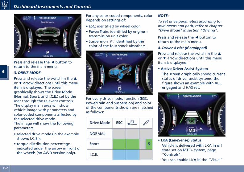
Press and release the◄ button toreturn to the main menu.
3. DRIVE MODE
Press and release the switch in the ▲or▼ arrow directions until this menuitem is displayed. The screengraphically shows the Drive Mode(Normal, Sport, and I.C.E.) set by theuser through the relevant controls.The display main area will showvehicle image with parameters andcolor-coded components affected bythe selected drive mode.The image will show the followingparameters:
• selected drive mode (in the exampleshown: I.C.E.);
• torque distribution percentageindicated under the arrow in front ofthe wheels (on AWD version only).
For any color-coded components, colordepends on settings of:
• ESC: identified by wheel color.• PowerTrain: identified by engine +transmission unit color.
• Suspension : identified by thecolor of the four shock absorbers.
For every drive mode, function (ESC,PowerTrain and Suspension) and colorof the components shown are matchedas follows:
NOTE:
To set drive parameters according toown needs and path, refer to chapter“Drive Mode” in section “Driving”.
Press and release the◄ button toreturn to the main menu.
4. Driver Assist (if equipped)
Press and release the switch in the ▲or▼ arrow directions until this menuitem is displayed.
• Active Driver Assist SystemThe screen graphically shows currentstatus of driver assist systems: thefigure shows an example with ACCengaged and HAS set.
• LKA (LaneSense) StatusVehicle is delivered with LKA in offstate set on MTC+ system, page"Controls".You can enable LKA in the ”Visual”
Dashboard Instruments and Controls
4
152
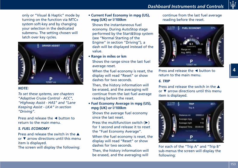
only or “Visual & Haptic” mode byturning on the function via MTC+system soft-key and by changingyour selection in the dedicatedsubmenu. The setting chosen willlatch over key cycles.
NOTE:
To set these systems, see chapters“Adaptive Cruise Control - ACC”,"Highway Assist - HAS" and “LaneKeeping Assist - LKA” in section“Driving”.
Press and release the◄ button toreturn to the main menu.
5. FUEL ECONOMY
Press and release the switch in the ▲or▼ arrow directions until this menuitem is displayed.The screen will display the following:
• Current Fuel Economy in mpg (US),mpg (UK) or l/100kmShows the instantaneous fueleconomy. During AutoStop stageperformed by the Start&Stop system(see “Normal Starting of theEngine” in section “Driving”), adash will be displayed instead of thevalue.
• Range in miles or kmShows the range since the last fuelaverage reset.When the fuel economy is reset, thedisplay will read “Reset” or showdashes for two seconds.Then, the history information willbe erased, and the averaging willcontinue from the last fuel averagereading before the reset.
• Fuel Economy Average in mpg (US),mpg (UK) or l/100kmShows the average fuel economysince the last reset.Press the multifunction switch (►)for 1 second and release it to resetthe “Fuel Economy Average”.When the fuel economy is reset, thedisplay will read “Reset” or showdashes for two seconds.Then, the history information willbe erased, and the averaging will
continue from the last fuel averagereading before the reset.
Press and release the◄ button toreturn to the main menu.
6. TRIP
Press and release the switch in the ▲or▼ arrow directions until this menuitem is displayed.
For each of the “Trip A” and “Trip B”sub-menus the screen will display thefollowing:
Dashboard Instruments and Controls
4
153
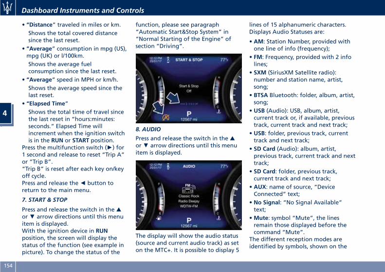
• “Distance” traveled in miles or km.Shows the total covered distancesince the last reset.
• “Average” consumption in mpg (US),mpg (UK) or l/100km.Shows the average fuelconsumption since the last reset.
• “Average” speed in MPH or km/h.Shows the average speed since thelast reset.
• “Elapsed Time”Shows the total time of travel sincethe last reset in “hours:minutes:seconds.” Elapsed Time willincrement when the ignition switchis in the RUN or START position.
Press the multifunction switch (►) for1 second and release to reset “Trip A”or “Trip B”.“Trip B” is reset after each key on/keyoff cycle.Press and release the◄ button toreturn to the main menu.
7. START & STOP
Press and release the switch in the ▲or▼ arrow directions until this menuitem is displayed.With the ignition device in RUNposition, the screen will display thestatus of the function (see example inpicture). To change the status of the
function, please see paragraph“Automatic Start&Stop System” in“Normal Starting of the Engine” ofsection “Driving”.
8. AUDIO
Press and release the switch in the ▲or▼ arrow directions until this menuitem is displayed.
The display will show the audio status(source and current audio track) as seton the MTC+. It is possible to display 5
lines of 15 alphanumeric characters.Displays Audio Statuses are:
• AM: Station Number, provided withone line of info (frequency);
• FM: Frequency, provided with 2 infolines;
• SXM (SiriusXM Satellite radio):number and station name, artist,song;
• BTSA Bluetooth: folder, album, artist,song;
• USB (Audio): USB, album, artist,current track or, if available, previoustrack, current track and next track;
• USB: folder, previous track, currenttrack and next track;
• SD Card (Audio): album, artist,previous track, current track and nexttrack;
• SD Card: folder, previous track,current track and next track;
• AUX: name of source, “DeviceConnected” text;
• No Signal: “No Signal Available”text;
•Mute: symbol “Mute”, the linesremain those displayed before thecommand “Mute”.
The different reception modes areidentified by symbols, shown on the
Dashboard Instruments and Controls
4
154

display above the info lines. The chartindicates their meaning.
AM
FM
AUX
SD
SXM Satellite Radio
USB
• Many signals• Signal not available
BTSA
App
Audio mute
Press and release the◄ button toreturn to the main menu.
9. STORED MESSAGES
Press and release the central switch inthe ▲ or▼ arrow directions until thismenu item is displayed.The system will either display thenumber of the stored messages (if anyavailable) or “No Stored Messages” asshown in picture.
Press and release the switch in the ▲or▼ arrow directions to scroll thestored messages.When the number of messagesexceeds 9, the submenu points will bereplaced by a numerical valueindicating the message number. Pressand release the switch (►) to view theselected message (see example in thepicture).
Press and release the◄ button toreturn to the main menu.
Dashboard Instruments and Controls
4
155
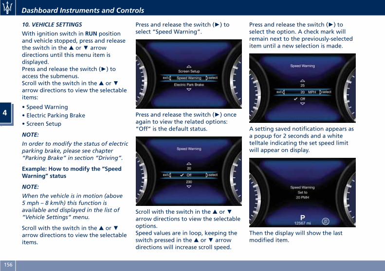
10. VEHICLE SETTINGS
With ignition switch in RUN positionand vehicle stopped, press and releasethe switch in the ▲ or▼ arrowdirections until this menu item isdisplayed.Press and release the switch (►) toaccess the submenus.Scroll with the switch in the ▲ or▼arrow directions to view the selectableitems:
• Speed Warning• Electric Parking Brake• Screen Setup
NOTE:
In order to modify the status of electricparking brake, please see chapter“Parking Brake” in section “Driving”.
Example: How to modify the “SpeedWarning” status
NOTE:
When the vehicle is in motion (above5 mph – 8 km/h) this function isavailable and displayed in the list of“Vehicle Settings” menu.
Scroll with the switch in the ▲ or▼arrow directions to view the selectableitems.
Press and release the switch (►) toselect “Speed Warning”.
Press and release the switch (►) onceagain to view the related options:“Off” is the default status.
Scroll with the switch in the ▲ or▼arrow directions to view the selectableoptions.Speed values are in loop, keeping theswitch pressed in the ▲ or▼ arrowdirections will increase scroll speed.
Press and release the switch (►) toselect the option. A check mark willremain next to the previously-selecteditem until a new selection is made.
A setting saved notification appears asa popup for 2 seconds and a whitetelltale indicating the set speed limitwill appear on display.
Then the display will show the lastmodified item.
Dashboard Instruments and Controls
4
156
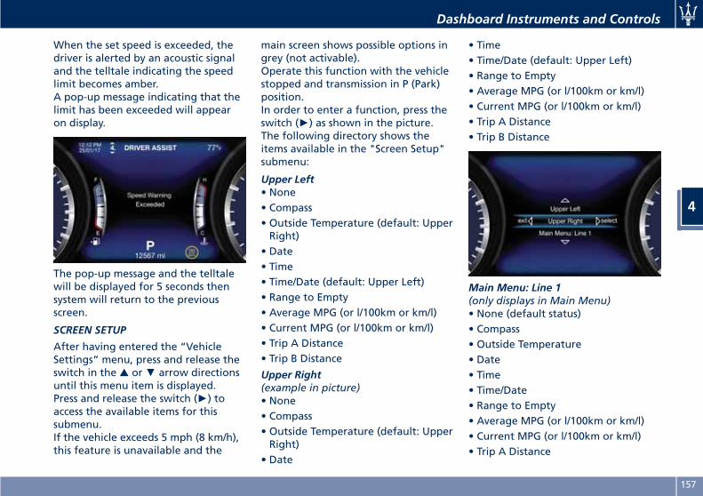
When the set speed is exceeded, thedriver is alerted by an acoustic signaland the telltale indicating the speedlimit becomes amber.A pop-up message indicating that thelimit has been exceeded will appearon display.
The pop-up message and the telltalewill be displayed for 5 seconds thensystem will return to the previousscreen.
SCREEN SETUP
After having entered the “VehicleSettings” menu, press and release theswitch in the ▲ or▼ arrow directionsuntil this menu item is displayed.Press and release the switch (►) toaccess the available items for thissubmenu.If the vehicle exceeds 5 mph (8 km/h),this feature is unavailable and the
main screen shows possible options ingrey (not activable).Operate this function with the vehiclestopped and transmission in P (Park)position.In order to enter a function, press theswitch (►) as shown in the picture.The following directory shows theitems available in the "Screen Setup"submenu:
Upper Left• None• Compass• Outside Temperature (default: UpperRight)
• Date• Time• Time/Date (default: Upper Left)• Range to Empty• Average MPG (or l/100km or km/l)• Current MPG (or l/100km or km/l)• Trip A Distance• Trip B Distance
Upper Right(example in picture)• None• Compass• Outside Temperature (default: UpperRight)
• Date
• Time• Time/Date (default: Upper Left)• Range to Empty• Average MPG (or l/100km or km/l)• Current MPG (or l/100km or km/l)• Trip A Distance• Trip B Distance
Main Menu: Line 1(only displays in Main Menu)• None (default status)• Compass• Outside Temperature• Date• Time• Time/Date• Range to Empty• Average MPG (or l/100km or km/l)• Current MPG (or l/100km or km/l)• Trip A Distance
Dashboard Instruments and Controls
4
157
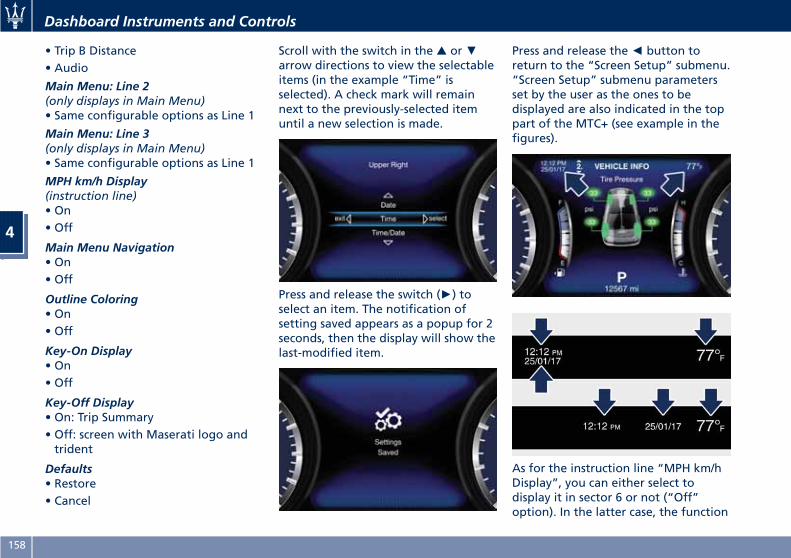
• Trip B Distance• Audio
Main Menu: Line 2(only displays in Main Menu)• Same configurable options as Line 1
Main Menu: Line 3(only displays in Main Menu)• Same configurable options as Line 1
MPH km/h Display(instruction line)• On• Off
Main Menu Navigation• On• Off
Outline Coloring• On• Off
Key-On Display• On• Off
Key-Off Display• On: Trip Summary• Off: screen with Maserati logo andtrident
Defaults• Restore• Cancel
Scroll with the switch in the ▲ or▼arrow directions to view the selectableitems (in the example “Time” isselected). A check mark will remainnext to the previously-selected itemuntil a new selection is made.
Press and release the switch (►) toselect an item. The notification ofsetting saved appears as a popup for 2seconds, then the display will show thelast-modified item.
Press and release the◄ button toreturn to the “Screen Setup” submenu.“Screen Setup” submenu parametersset by the user as the ones to bedisplayed are also indicated in the toppart of the MTC+ (see example in thefigures).
As for the instruction line “MPH km/hDisplay”, you can either select todisplay it in sector 6 or not (“Off”option). In the latter case, the function
Dashboard Instruments and Controls
4
158
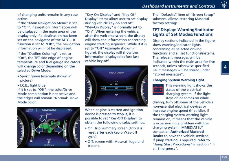
of changing units remains in any caseactive.If the “Main Navigation Menu” is setto “On”, navigation information willbe displayed in the main area of thedisplay only if a destination has beenset on the navigator of the MTC+. Iffunction is set to "Off", the navigationinformation will not be displayed.
If the “Outline Coloring” is set to“On”, the TFT side edge of enginetemperature and fuel gauge indicatorswill change color depending on theselected Drive Mode:
• Sport: green (example shown inpicture);
• I.C.E.: light blue.If it is set to "Off", the color/DriveMode combination is not active andthe edges will remain "Normal" DriveMode color.
“Key-On Display” and “Key-OffDisplay” items allow user to set displayduring vehicle key-on and off.“Key-On Display” is normally set to“On”. When entering the vehicle,after the welcome screen, the displaywill show the information concerningengine starting sequence. While if it isset to “Off” (example shown infigure), the display will show theinformation displayed before lastvehicle key-off.
When engine is started and ignitiondevice is pressed to stop it, it ispossible to set “Key-Off Display” toobtain the following display settings:
• On: Trip Summary screen (Trip B isreset after each key-on/key-offcycle);
• Off: screen with Maserati logo andtrident.
The “Defaults” item of “Screen Setup”submenu allows restoring Maseratifactory settings.
TFT Display: Warning/IndicatorLights of Set Modes/FunctionsDisplay sections indicated in the figureshow warning/indicator lightsconcerning all selected drivingfunctions and all set functions/systems.The relevant messages will beindicated within the main area for fiveseconds, unless otherwise specified.Fault messages will be stored under“Stored messages”.
Charging System Warning Light
This warning light shows thestatus of the electricalcharging system. If the lightstays on or comes on while
driving, turn off some of the vehicle'snon-essential electrical devices orincrease engine speed (if at idle). Ifthe charging system warning lightremains on, it means that the vehicleis experiencing a problem with thecharging system. IMMEDIATELYcontact an Authorized MaseratiDealer to have the vehicle serviced.If jump starting is required, refer to“Jump Start Procedures” in section “Inan Emergency”.
Dashboard Instruments and Controls
4
159
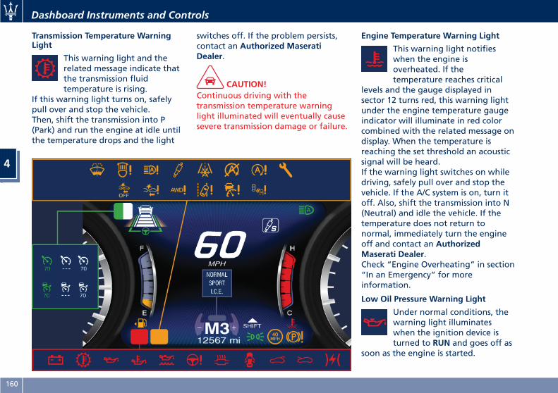
Transmission Temperature WarningLight
This warning light and therelated message indicate thatthe transmission fluidtemperature is rising.
If this warning light turns on, safelypull over and stop the vehicle.Then, shift the transmission into P(Park) and run the engine at idle untilthe temperature drops and the light
switches off. If the problem persists,contact an Authorized MaseratiDealer.
CAUTION!Continuous driving with thetransmission temperature warninglight illuminated will eventually causesevere transmission damage or failure.
Engine Temperature Warning Light
This warning light notifieswhen the engine isoverheated. If thetemperature reaches critical
levels and the gauge displayed insector 12 turns red, this warning lightunder the engine temperature gaugeindicator will illuminate in red colorcombined with the related message ondisplay. When the temperature isreaching the set threshold an acousticsignal will be heard.If the warning light switches on whiledriving, safely pull over and stop thevehicle. If the A/C system is on, turn itoff. Also, shift the transmission into N(Neutral) and idle the vehicle. If thetemperature does not return tonormal, immediately turn the engineoff and contact an AuthorizedMaserati Dealer.Check “Engine Overheating” in section“In an Emergency” for moreinformation.
Low Oil Pressure Warning Light
Under normal conditions, thewarning light illuminateswhen the ignition device isturned to RUN and goes off as
soon as the engine is started.
Dashboard Instruments and Controls
4
160
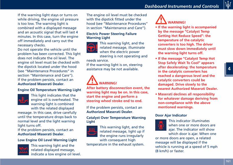
If the warning light stays or turns onwhile driving, the engine oil pressureis too low. The warning light iscombined with a displayed messageand an acoustic signal that will last 4minutes. In this case, turn the engineoff immediately and carry out thenecessary checks.Do not operate the vehicle until theproblem has been corrected. This lightdoes not indicate the oil level. Theengine oil level must be checked withthe dipstick located under the hood(see “Maintenance Procedures” insection “Maintenance and Care”).If the problem persists, contact anAuthorized Maserati Dealer.
Engine Oil Temperature Warning Light
This light indicates that theengine oil is overheated. Thewarning light is combinedwith the related displayed
message. In this case, drive carefullyuntil the temperature drops back tonormal level and the light warninglight turns off.If the problem persists, contact anAuthorized Maserati Dealer.
Low Engine Oil Level Warning Light
This warning light and therelated displayed message,indicate a low engine oil level.
The engine oil level must be checkedwith the dipstick fitted under thehood (see “Maintenance Procedures”in section “Maintenance and Care”).
Electric Power Steering FailureWarning Light
This warning light, and therelated message, illuminatewhen the electric powersteering is not operating and
needs service.If the warning light is on, steeringassistance may be not available.
WARNING!After battery disconnection event, thewarning light may be on. In this case,start the engine and perform asteering wheel stroke end to end.
If the problem persists, contact anAuthorized Maserati Dealer.
Catalyst Over Temperature WarningLight
This warning light, and therelated message, light up ifthe engine runs irregularlywith consequent high
temperature in the exhaust system.
WARNING!• If the warning light is accompaniedby the message “Catalyst TempGetting Hot Reduce Speed”: thetemperature of the catalyticconverters is too high. The drivermust slow down immediately untilthe warning light turns off.
• If the message “Catalyst Temp HotStop Safely Wait To Cool” appearsafter decelerating: the temperaturein the catalytic converters hasreached a dangerous level and thecatalytic converters could bedamaged. Drive slowly to thenearest Authorized Maserati Dealer.
•Maserati declines all responsibilityfor whatever damage deriving fromnon-compliance with the abovementioned warnings.
Door Ajar Indicator
This indicator illuminateswhen one or more doors areajar. The indicator will showwhich door is ajar. When one
or more doors are open, a relatedmessage will be displayed if thevehicle is running at a speed of 5 mph(8 km/h) or faster.
Dashboard Instruments and Controls
4
161
Trunk Lid and Hood Ajar Indicators
These light indicators willilluminate to indicate that thetrunk lid and/or the hood areajar.When the trunk lid or thehood is open, a relatedmessage will be displayed
besides the light if the vehicle isrunning at a speed of 5 mph (8 km/h)or faster.
Electronic Throttle Control (ETC)Indicator
This indicator light indicates afailure of the ElectronicThrottle Control (ETC) system.If the indicator turns on while
driving (a torque decrease is possible),have the system checked by anAuthorized Maserati Dealer.When detecting a failure, the lightindicator will illuminate while theengine is running.If the indicator remains lit with theengine running, you can still drive yourvehicle. However, contact anAuthorized Maserati Dealer as soon aspossible.If the indicator is flashing while theengine is running, immediate service isrequired. You may experience reducedperformance, an elevated/rough idle
or engine stall and your vehicle mayrequire towing.
Low Fuel Indicator
When the fuel level reachesapproximately 4.2 Gallons (16litres) this light under the fuelgauge indicator will turn on,
and remain on until fuel is addedtogether with the related message. Inthis condition the color indicating thequantity of fuel in the tank, inside theindicator on display, will go fromwhite to amber.Refer to “Refueling” in section“Driving” for fuel filling.
Windshield Washer Low FluidIndicator
This indicator will illuminatefor 5 seconds to indicate a lowlevel of the windshield washerfluid. A related message will
be displayed.See “Maintenance Procedures” insection “Maintenance and Care” forfluid filling.
Headlight Aiming System FailureWarning Light
This warning light and therelated message indicate afailure of the automaticheadlight aiming system.
Please contact an Authorized MaseratiDealer to check the system.
Automatic High Beam Failure WarningLight
This warning light and therelated message illuminate toreport a failure of theautomatic high beam
headlights.Contact an Authorized MaseratiDealer as soon as possible.
Suspensions Failure Warning Light
This warning light and therelated message turn on whiledriving if there is a failure ofthe suspension system (only
with optional Skyhook activesuspension).Please contact an Authorized MaseratiDealer to check the system.
Ice Hazard Indicator
When the externaltemperature falls below 38°F(3°C), the temperature valueblinks for a few seconds, the
indicator light turns on, a message isdisplayed and an acoustic signal istriggered to warn the driver of the riskof icy roadbed.Under such conditions, we recommendusing the I.C.E. drive mode (see
Dashboard Instruments and Controls
4
162
“Automatic Transmission” in section“Driving”) drive carefully and slowdown as the grip of the tires may besignificantly reduced.The indicator light flashes for 5seconds and switches off when thetemperature reaches 43°F (6°C) orhigher.
Electric Parking Brake Failure WarningLight
This warning light and relatedmessage illuminate whenthere is an EPB system failure.The failure could also
completely or partially block thevehicle because the parking brakecould remain on even after it has beenautomatically or manually disengagedthough its controls.If it is still possible to use the vehicle(parking brake not engaged) drive tothe nearest Authorized MaseratiDealer and remember to performingeach operation/command that theelectric parking brake is notfunctioning.
Start&Stop Disable Indicator
This indicator illuminateswhen Start&Stop is turned offthrough the controls locatedon the right side of the
steering wheel. See paragraph
“Automatic Start&Stop System” inchapter “Normal Starting of theEngine” of section “Driving” forfurther information.
Start&Stop Failure Warning Light
This warning light illuminateswhen there is a failure in theStart&Stop system. Switch theengine on or off using the
normal procedure with the ignitiondevice START/STOP and have thevehicle checked at an AuthorizedMaserati Dealer.
Scheduled Maintenance (Service)Indicator
This indicator illuminates anda message flashes on thedisplay for approximately 5seconds after an acoustic
signal to indicate that the nextscheduled maintenance is due or isalready overdue.Unless reset, the message willcontinue to display each time youcycle the ignition to the RUN position.To turn off the message temporarily,press and release the◄ button on thesteering wheel. To reset the serviceindicator system, please visit anAuthorized Maserati Dealer.
ADAS Status Indicators (if equipped)
When you are not viewing the“Drive Assist” page, theindicators at the top left-handside of the display indicate
status of individual ADAS system orthe combination of them (see
examples).For further details, refer to“Adaptive Cruise Control -ACC”, “Lane Keeping Assist -
LKA” and “Highway Assist - HAS” insection “Driving”.
Forward Collision Warning (FCW) Off(If equipped)
This warning light informs thedriver that Forward CollisionWarning (FCW) is disabled. Ifthis light occurs together with
other specific messages, take yourvehicle to an Authorized MaseratiDealer for service. This warning lightwill light even when the activation ofanother driver assistance feature ordrive mode (such as “ -ESC OFF”)disables the FCW.
Forward Collision Warning (FCW)Fault (If equipped)
This warning light informsthat FCW is in fault state. Ifthis occurred together withother specific messages, could
Dashboard Instruments and Controls
4
163
mean that a system fault requiringservicing at an Authorized MaseratiDealer. It is nevertheless possible todrive the vehicle without using thisfunction (for further details, refer to“Forward Collision Warning - FCW” insection “Driving”).
AWD Failure Warning Light (on AWDversion only)
This warning light turns on toindicate a fault of the AWDsystem. Contact an AuthorizedMaserati Dealer as soon as
possible, and avoid using the vehicle inheavy duty conditions.
Set Passive Speed Limit
This indicator light indicatesthe passive speed limit set viathe controls on the RH side ofthe steering wheel (for further
details, refer to “TFT Display: Menusand Settings” in this chapter).
Passive Speed Limit Exceeded
This indicator light informs thedriver that the speed limit thatwas set has been exceeded.
Stiff Suspension Setting Indicator
This indicator light indicatesthat the stiff suspensionsprogram (S) is on. For further
details, refer to “Drive Mode” insection “Driving”.
Set Drive Mode Indicator
Drive mode set by the driverthrough the controls oncentral console is displayedabove the transmission leverindicator.For further details, refer to“Drive Mode” in section“Driving”.
Cruise Control (CC) Ready or Canceled
This white light indicator willilluminate when the CC isready to be set (with 3 dashesbelow) and, once it sets, when
it is temporarily canceled (set speed inwhite below).For further information, check“Electronic Cruise Control” in section“Driving”.
Cruise Control (CC) Set
This green light indicator willilluminate with the set speedwhen the CC is set and indriver override. For further
information, check “Electronic CruiseControl” in section “Driving”.
Lane Keeping Assist (LKA) Fault
This warning light on indicatesthat the LKA system is in fault.If the warning light and therelevant message do not go
off after a few manoeuvres andeventually a key cycle, contact anAuthorized Maserati Dealer.
Adaptive Cruise Control (ACC) Readyor Canceled
This white warning lightindicates that the ACC is readyto be set (with 3 dashes below)and, once it sets, when it is
temporarily canceled (set speed inwhite below). For further details, referto “Adaptive Cruise Control - ACC” insection “Driving”.
Adaptive Cruise Control (ACC) Set
This green warning light withbelow the set speed turns onwhen the ACC is set (forfurther details, refer to
“Adaptive Cruise Control - ACC” insection “Driving”) and vehicle willkeep set speed.
Adaptive Cruise Control (ACC) Fault (ifequipped)
This warning light turns onwhen ACC is not operating orneeds servicing, For further
Dashboard Instruments and Controls
4
164
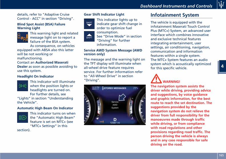
details, refer to “Adaptive CruiseControl - ACC” in section “Driving”.
Blind Spot Assist (BSA) FailureWarning Light
This warning light and relatedmessage light on to report afailure of the BSA system.As consequence, on vehicles
equipped with ABSA also this latterwill be not working ormalfunctioning.Contact an Authorized MaseratiDealer as soon as possible avoiding touse this system.
Headlight On Indicator
This indicator will illuminatewhen the position lights orheadlights are turned on.For further details, see
“Lights” in section “Understandingthe Vehicle”.
Automatic High Beam On Indicator
This indicator turns on whenthe “Automatic High Beam”feature is set on MTC+ (see“MTC+ Settings” in this
section).
Gear Shift Indicator Light
This indicator lights up toindicate gear shift change inorder to optimize fuelconsumption.See “Drive Mode” in section“Driving” for furtherinformation.
Service AWD System Message (AWDversion only)
The message and the warning light onthe TFT display will illuminate whenall-wheel drive feature requiresservice. For further information referto “All-Wheel Drive” in section“Driving”.
Infotainment SystemThe vehicle is equipped with theinfotainment Maserati Touch ControlPlus (MTC+) System, an advanced userinterface which combines innovativeand exclusive technical featuresintegrating entertainment, usersettings, air conditioning, navigation,communication and informationfeatures within a single system.The MTC+ System features an audiosystem which is acoustically optimizedfor this specific vehicle.
WARNING!The navigation system assists thedriver while driving, providing adviceand suggestions, by voice guidanceand graphic information, for the bestroute to reach the set destination. Thesuggestions provided by thenavigation system do not relieve thedriver from full responsibility for themanoeuvres made through trafficwhile driving, or from compliancewith road regulations and otherprovisions regarding road traffic. Theperson driving the vehicle is alwaysand in any case responsible for safedriving on the road.
Dashboard Instruments and Controls
4
165
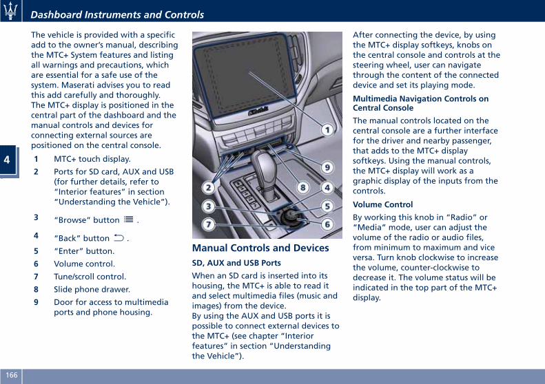
The vehicle is provided with a specificadd to the owner’s manual, describingthe MTC+ System features and listingall warnings and precautions, whichare essential for a safe use of thesystem. Maserati advises you to readthis add carefully and thoroughly.The MTC+ display is positioned in thecentral part of the dashboard and themanual controls and devices forconnecting external sources arepositioned on the central console.
1 MTC+ touch display.
2 Ports for SD card, AUX and USB(for further details, refer to“Interior features” in section“Understanding the Vehicle”).
3 “Browse” button .
4 “Back” button .
5 “Enter” button.
6 Volume control.
7 Tune/scroll control.
8 Slide phone drawer.
9 Door for access to multimediaports and phone housing.
Manual Controls and DevicesSD, AUX and USB Ports
When an SD card is inserted into itshousing, the MTC+ is able to read itand select multimedia files (music andimages) from the device.By using the AUX and USB ports it ispossible to connect external devices tothe MTC+ (see chapter “Interiorfeatures” in section “Understandingthe Vehicle”).
After connecting the device, by usingthe MTC+ display softkeys, knobs onthe central console and controls at thesteering wheel, user can navigatethrough the content of the connecteddevice and set its playing mode.
Multimedia Navigation Controls onCentral Console
The manual controls located on thecentral console are a further interfacefor the driver and nearby passenger,that adds to the MTC+ displaysoftkeys. Using the manual controls,the MTC+ display will work as agraphic display of the inputs from thecontrols.
Volume Control
By working this knob in “Radio” or“Media” mode, user can adjust thevolume of the radio or audio files,from minimum to maximum and viceversa. Turn knob clockwise to increasethe volume, counter-clockwise todecrease it. The volume status will beindicated in the top part of the MTC+display.
Dashboard Instruments and Controls
4
166
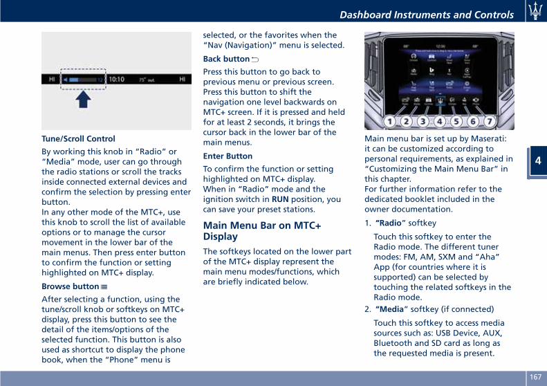
Tune/Scroll Control
By working this knob in “Radio” or“Media” mode, user can go throughthe radio stations or scroll the tracksinside connected external devices andconfirm the selection by pressing enterbutton.In any other mode of the MTC+, usethis knob to scroll the list of availableoptions or to manage the cursormovement in the lower bar of themain menus. Then press enter buttonto confirm the function or settinghighlighted on MTC+ display.
Browse button
After selecting a function, using thetune/scroll knob or softkeys on MTC+display, press this button to see thedetail of the items/options of theselected function. This button is alsoused as shortcut to display the phonebook, when the “Phone” menu is
selected, or the favorites when the“Nav (Navigation)” menu is selected.
Back button
Press this button to go back toprevious menu or previous screen.Press this button to shift thenavigation one level backwards onMTC+ screen. If it is pressed and heldfor at least 2 seconds, it brings thecursor back in the lower bar of themain menus.
Enter Button
To confirm the function or settinghighlighted on MTC+ display.When in “Radio” mode and theignition switch in RUN position, youcan save your preset stations.
Main Menu Bar on MTC+DisplayThe softkeys located on the lower partof the MTC+ display represent themain menu modes/functions, whichare briefly indicated below.
Main menu bar is set up by Maserati:it can be customized according topersonal requirements, as explained in“Customizing the Main Menu Bar” inthis chapter.For further information refer to thededicated booklet included in theowner documentation.
1. “Radio” softkey
Touch this softkey to enter theRadio mode. The different tunermodes: FM, AM, SXM and “Aha”App (for countries where it issupported) can be selected bytouching the related softkeys in theRadio mode.
2. “Media” softkey (if connected)
Touch this softkey to access mediasources such as: USB Device, AUX,Bluetooth and SD card as long asthe requested media is present.
Dashboard Instruments and Controls
4
167
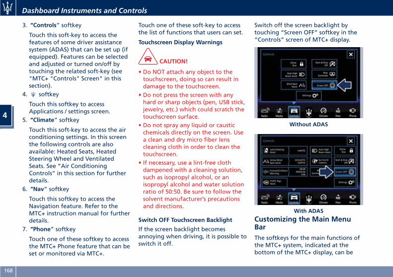
3. “Controls” softkey
Touch this soft-key to access thefeatures of some driver assistancesystem (ADAS) that can be set up (ifequipped). Features can be selectedand adjusted or turned on/off bytouching the related soft-key (see"MTC+ "Controls" Screen" in thissection).
4. softkey
Touch this softkey to accessApplications / settings screen.
5. “Climate” softkey
Touch this soft-key to access the airconditioning settings. In this screenthe following controls are alsoavailable: Heated Seats, HeatedSteering Wheel and VentilatedSeats. See “Air ConditioningControls” in this section for furtherdetails.
6. “Nav” softkey
Touch this softkey to access theNavigation feature. Refer to theMTC+ instruction manual for furtherdetails.
7. “Phone” softkey
Touch one of these softkey to accessthe MTC+ Phone feature that can beset or monitored via MTC+.
Touch one of these soft-key to accessthe list of functions that users can set.
Touchscreen Display Warnings
CAUTION!
• Do NOT attach any object to thetouchscreen, doing so can result indamage to the touchscreen.
• Do not press the screen with anyhard or sharp objects (pen, USB stick,jewelry, etc.) which could scratch thetouchscreen surface.
• Do not spray any liquid or causticchemicals directly on the screen. Usea clean and dry micro fiber lenscleaning cloth in order to clean thetouchscreen.
• If necessary, use a lint-free clothdampened with a cleaning solution,such as isopropyl alcohol, or anisopropyl alcohol and water solutionratio of 50:50. Be sure to follow thesolvent manufacturer’s precautionsand directions.
Switch OFF Touchscreen Backlight
If the screen backlight becomesannoying when driving, it is possible toswitch it off.
Switch off the screen backlight bytouching “Screen OFF” softkey in the“Controls” screen of MTC+ display.
Customizing the Main MenuBarThe softkeys for the main functions ofthe MTC+ system, indicated at thebottom of the MTC+ display, can be
Without ADAS
With ADAS
Dashboard Instruments and Controls
4
168
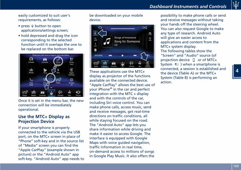
easily customized to suit user'srequirements, as follows:
• press button to openapplications/settings screen;
• hold depressed and drag the iconcorresponding to the selectedfunction until it overlaps the one tobe replaced on the bottom bar.
Once it is set in the menu bar, the newconnection will be immediatelyoperational.
Use the MTC+ Display asProjection DeviceIf your smartphone is properlyconnected to the vehicle via the USBport, on the MTC+ screen in place of“Phone” soft-key and in the source listof “Media” screen you can find the“Apple CarPlay” (example shown inpicture) or the “Android Auto” appsoft-key. “Android Auto” app needs to
be downloaded on your mobiledevice.
These applications use the MTC+display as projector of the functionsavailable on the connected device.“Apple CarPlay” allows the best use ofyour iPhone® in the car and perfectintegration with the MTC + displayand with the controls of the car,including Siri voice control. You canmake phone calls, access music, sendand receive messages, get real-timedirections on traffic conditions, allwhile staying focused on the road.The “Android Auto” app lets youshare information while driving andmake it easier to access Google. Theinterface is equipped with GoogleMaps with voice guided navigation,traffic information in real time,on-demand access to millions of songsin Google Play Music. It also offers the
possibility to make phone calls or sendand receive messages without takingyour hands off the steering wheel.You can also request Google to makeany type of research. Android Autowill give an easier access toapplications and content from theMTC+ system display.The following tables show the“Screen” and “Audio” source (ofprojection device or of MTC+System MTC+ ) when a smartphone isconnected, a session is established andthe device (Table A) or the MTC+System (Table B) is performing anaction.
Dashboard Instruments and Controls
4
169
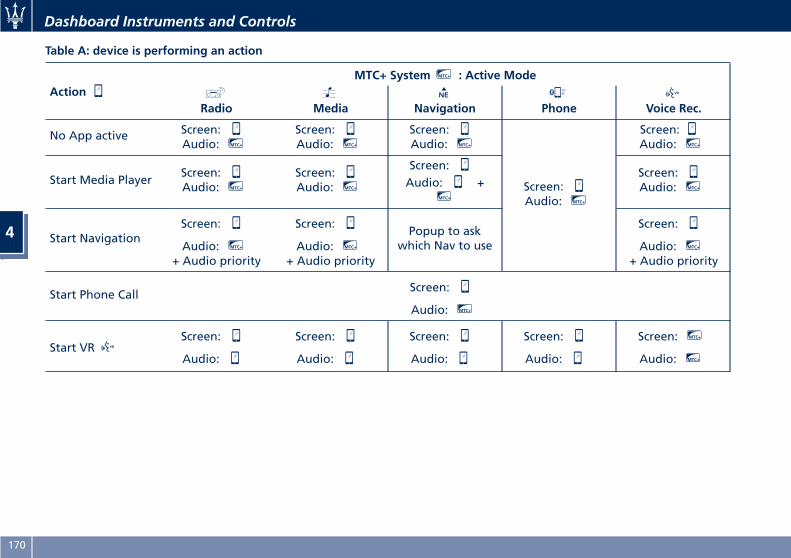
Table A: device is performing an action
ActionMTC+ System MTC+ : Active Mode
Radio Media Navigation Phone Voice Rec.
No App active Screen:Audio: MTC+
Screen:Audio: MTC+
Screen:Audio: MTC+
Screen:Audio: MTC+
Screen:Audio: MTC+
Start Media PlayerScreen:Audio: MTC+
Screen:Audio: MTC+
Screen:Audio: +
MTC+
Screen:Audio: MTC+
Start NavigationScreen:
Audio: MTC+
+ Audio priority
Screen:
Audio: MTC+
+ Audio priority
Popup to askwhich Nav to use
Screen:
Audio: MTC+
+ Audio priority
Start Phone CallScreen:
Audio: MTC+
Start VRScreen:
Audio:
Screen:
Audio:
Screen:
Audio:
Screen:
Audio:
Screen: MTC+
Audio: MTC+
Dashboard Instruments and Controls
4
170
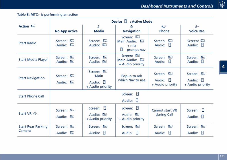
Table B: MTC+ is performing an action
Action MTC+
Device : Active Mode
No App active Media Navigation Phone Voice Rec.
Start RadioScreen: MTC+
Audio: MTC+
Screen: MTC+
Audio: MTC+
Screen: MTC+
Main Audio: MTC+
+ mixprompt nav
Screen: MTC+
Audio:Screen: MTC+
Audio:
Start Media PlayerScreen: MTC+
Audio: MTC+
Screen: MTC+
Audio: MTC+
Screen: MTC+
Main Audio: MTC+
+ Audio priority
Screen: MTC+
Audio:Screen: MTC+
Audio:
Start NavigationScreen: MTC+
Audio: MTC+
Screen: MTC+
Main
Audio:+ Audio priority
Popup to askwhich Nav to use
Screen: MTC+
Audio:+ Audio priority
Screen: MTC+
Audio:+ Audio priority
Start Phone CallScreen:
Audio:
Start VRScreen: MTC+
Audio: MTC+
Screen:
Audio: MTC+
+ Audio priority
Screen:
Audio: MTC+
+ Audio priority
Cannot start VRduring Call
Screen:
Audio:
Start Rear ParkingCamera
Screen: MTC+
Audio: MTC+
Screen: MTC+
Audio:
Screen: MTC+
Audio:
Screen: MTC+
Audio:
Screen: MTC+
Audio:
Dashboard Instruments and Controls
4
171
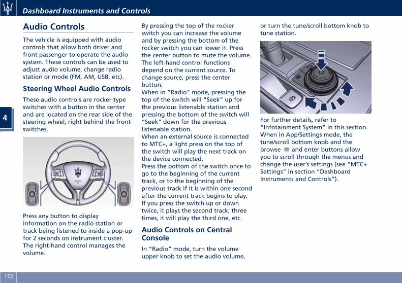
Audio ControlsThe vehicle is equipped with audiocontrols that allow both driver andfront passenger to operate the audiosystem. These controls can be used toadjust audio volume, change radiostation or mode (FM, AM, USB, etc).
Steering Wheel Audio ControlsThese audio controls are rocker-typeswitches with a button in the centerand are located on the rear side of thesteering wheel, right behind the frontswitches.
Press any button to displayinformation on the radio station ortrack being listened to inside a pop-upfor 2 seconds on instrument cluster.The right-hand control manages thevolume.
By pressing the top of the rockerswitch you can increase the volumeand by pressing the bottom of therocker switch you can lower it. Pressthe center button to mute the volume.The left-hand control functionsdepend on the current source. Tochange source, press the centerbutton.When in “Radio” mode, pressing thetop of the switch will “Seek” up forthe previous listenable station andpressing the bottom of the switch will“Seek” down for the previouslistenable station.When an external source is connectedto MTC+, a light press on the top ofthe switch will play the next track onthe device connected.Press the bottom of the switch once togo to the beginning of the currenttrack, or to the beginning of theprevious track if it is within one secondafter the current track begins to play.If you press the switch up or downtwice, it plays the second track; threetimes, it will play the third one, etc.
Audio Controls on CentralConsoleIn “Radio” mode, turn the volumeupper knob to set the audio volume,
or turn the tune/scroll bottom knob totune station.
For further details, refer to“Infotainment System” in this section.When in App/Settings mode, thetune/scroll bottom knob and thebrowse and enter buttons allowyou to scroll through the menus andchange the user’s settings (see “MTC+Settings” in section “DashboardInstruments and Controls”).
Dashboard Instruments and Controls
4
172
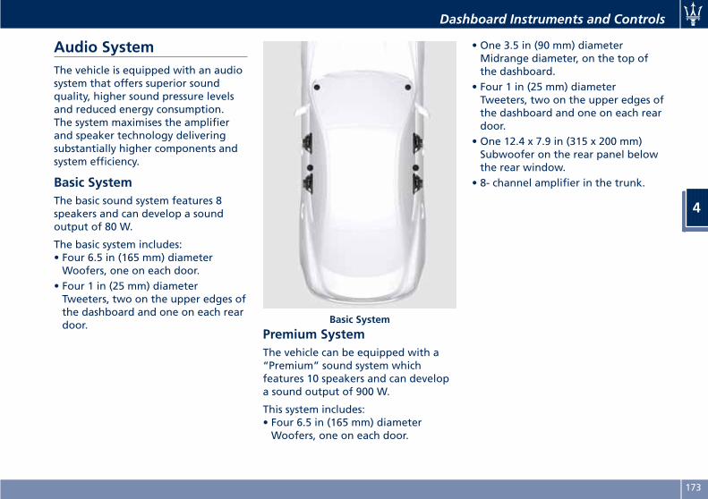
Audio SystemThe vehicle is equipped with an audiosystem that offers superior soundquality, higher sound pressure levelsand reduced energy consumption.The system maximises the amplifierand speaker technology deliveringsubstantially higher components andsystem efficiency.
Basic SystemThe basic sound system features 8speakers and can develop a soundoutput of 80 W.
The basic system includes:• Four 6.5 in (165 mm) diameterWoofers, one on each door.
• Four 1 in (25 mm) diameterTweeters, two on the upper edges ofthe dashboard and one on each reardoor.
Premium SystemThe vehicle can be equipped with a“Premium” sound system whichfeatures 10 speakers and can developa sound output of 900 W.
This system includes:• Four 6.5 in (165 mm) diameterWoofers, one on each door.
• One 3.5 in (90 mm) diameterMidrange diameter, on the top ofthe dashboard.
• Four 1 in (25 mm) diameterTweeters, two on the upper edges ofthe dashboard and one on each reardoor.
• One 12.4 x 7.9 in (315 x 200 mm)Subwoofer on the rear panel belowthe rear window.
• 8- channel amplifier in the trunk.
Basic System
Dashboard Instruments and Controls
4
173
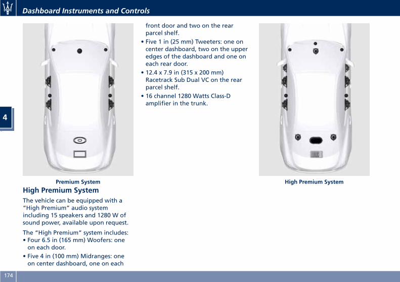
High Premium SystemThe vehicle can be equipped with a“High Premium” audio systemincluding 15 speakers and 1280 W ofsound power, available upon request.
The “High Premium” system includes:• Four 6.5 in (165 mm) Woofers: oneon each door.
• Five 4 in (100 mm) Midranges: oneon center dashboard, one on each
front door and two on the rearparcel shelf.
• Five 1 in (25 mm) Tweeters: one oncenter dashboard, two on the upperedges of the dashboard and one oneach rear door.
• 12.4 x 7.9 in (315 x 200 mm)Racetrack Sub Dual VC on the rearparcel shelf.
• 16 channel 1280 Watts Class-Damplifier in the trunk.
.Premium System High Premium System
Dashboard Instruments and Controls
4
174
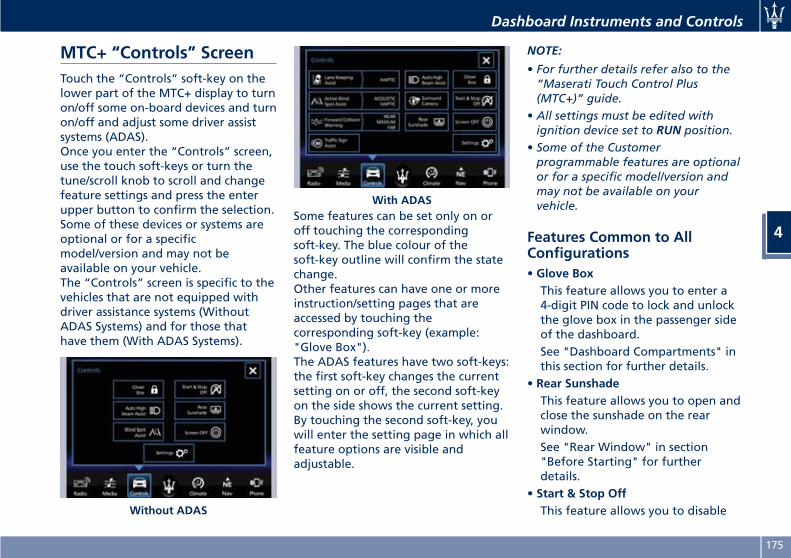
MTC+ “Controls” ScreenTouch the “Controls” soft-key on thelower part of the MTC+ display to turnon/off some on-board devices and turnon/off and adjust some driver assistsystems (ADAS).Once you enter the “Controls” screen,use the touch soft-keys or turn thetune/scroll knob to scroll and changefeature settings and press the enterupper button to confirm the selection.Some of these devices or systems areoptional or for a specificmodel/version and may not beavailable on your vehicle.The “Controls” screen is specific to thevehicles that are not equipped withdriver assistance systems (WithoutADAS Systems) and for those thathave them (With ADAS Systems).
Some features can be set only on oroff touching the correspondingsoft-key. The blue colour of thesoft-key outline will confirm the statechange.Other features can have one or moreinstruction/setting pages that areaccessed by touching thecorresponding soft-key (example:"Glove Box").The ADAS features have two soft-keys:the first soft-key changes the currentsetting on or off, the second soft-keyon the side shows the current setting.By touching the second soft-key, youwill enter the setting page in which allfeature options are visible andadjustable.
NOTE:
• For further details refer also to the“Maserati Touch Control Plus(MTC+)” guide.
• All settings must be edited withignition device set to RUN position.
• Some of the Customerprogrammable features are optionalor for a specific model/version andmay not be available on yourvehicle.
Features Common to AllConfigurations• Glove BoxThis feature allows you to enter a4-digit PIN code to lock and unlockthe glove box in the passenger sideof the dashboard.See "Dashboard Compartments" inthis section for further details.
• Rear SunshadeThis feature allows you to open andclose the sunshade on the rearwindow.See "Rear Window" in section"Before Starting" for furtherdetails.
• Start & Stop OffThis feature allows you to disableWithout ADAS
With ADAS
Dashboard Instruments and Controls
4
175
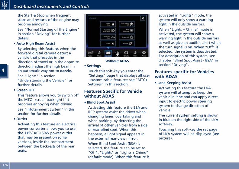
the Start & Stop when frequentstops and restarts of the engine maybecome annoying.See "Normal Starting of the Engine"in section "Driving" for furtherdetails.
• Auto High Beam AssistBy selecting this feature, when theforward digital camera detect avehicle that precedes in thedirection of travel or in the oppositedirection, adjust the high beam inan automatic way not to dazzle.See "Lights" in section"Understanding the Vehicle" forfurther details.
• Screen OFFThis feature allows you to switch offthe MTC+ screen backlight if itbecomes annoying when driving.See "Infotainment System" in thissection for further details.
• OutletActivating this feature an electricalpower converter allows you to usethe 115V AC-150W power outletthat may be present on someversions, inside the compartmentbetween the backrests of the rearseats.
• SettingsTouch this soft-key you enter the“Settings” page that displays all user- customizable features: see “MTC+Settings” in this section.
Features Specific for Vehiclewithout ADAS• Blind Spot AssistActivating this feature the BSA andRCP systems assist the driver whenchanging lanes, overtaking andwhen parking, by detecting thearrival of other vehicles from a sideor rear blind spot. When thishappens, a light signal appears inthe external rear-view mirror.When Blind Spot Assist (BSA) isselected, the feature can be set to“Off”, “Lights” or “Lights + Chime”(default mode). When this feature is
activated in “Lights” mode, thesystem will only show a warninglight in the outside mirrors.When “Lights + Chime” mode isactivated, the system will show awarning light in the outside mirrorsas well as give an audible alert whenthe turn signal is on. When “Off” isselected, the system is deactivated.For description of this system, seechapter “Blind Spot Assist - BSA” insection “Driving”.
Features specific for Vehicleswith ADAS• Lane Keeping AssistActivating this feature the LKAsystem will attempt to keep thevehicle in lane and can apply directinput to electric power steeringsystem to change direction ofvehicle.The current system setting is shownin blue on the right side of the LKAsoft-key.Touching this soft-key the set pageof LKA system will be displayed (seepicture).
Without ADAS
Dashboard Instruments and Controls
4
176
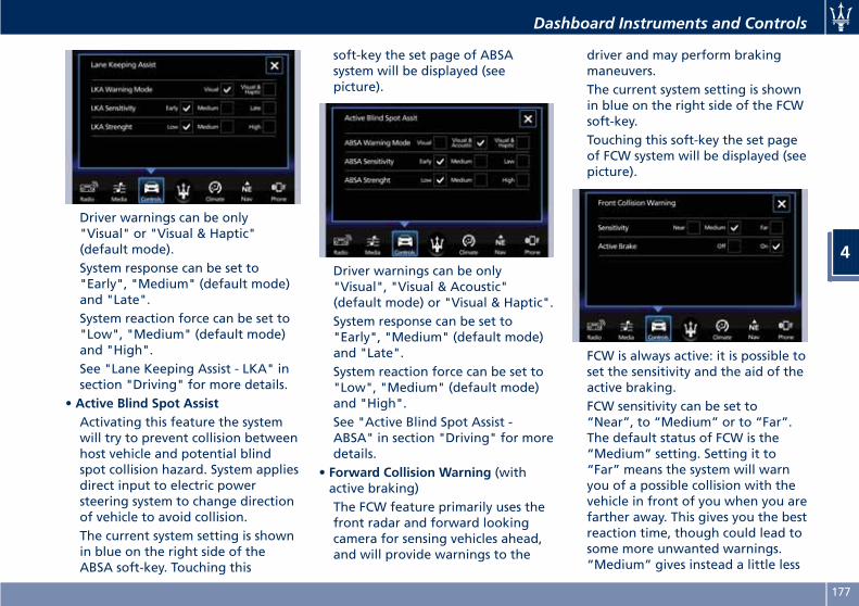
Driver warnings can be only"Visual" or "Visual & Haptic"(default mode).System response can be set to"Early", "Medium" (default mode)and "Late".System reaction force can be set to"Low", "Medium" (default mode)and "High".See "Lane Keeping Assist - LKA" insection "Driving" for more details.
• Active Blind Spot AssistActivating this feature the systemwill try to prevent collision betweenhost vehicle and potential blindspot collision hazard. System appliesdirect input to electric powersteering system to change directionof vehicle to avoid collision.The current system setting is shownin blue on the right side of theABSA soft-key. Touching this
soft-key the set page of ABSAsystem will be displayed (seepicture).
Driver warnings can be only"Visual", "Visual & Acoustic"(default mode) or "Visual & Haptic".System response can be set to"Early", "Medium" (default mode)and "Late".System reaction force can be set to"Low", "Medium" (default mode)and "High".See "Active Blind Spot Assist -ABSA" in section "Driving" for moredetails.
• Forward Collision Warning (withactive braking)The FCW feature primarily uses thefront radar and forward lookingcamera for sensing vehicles ahead,and will provide warnings to the
driver and may perform brakingmaneuvers.The current system setting is shownin blue on the right side of the FCWsoft-key.Touching this soft-key the set pageof FCW system will be displayed (seepicture).
FCW is always active: it is possible toset the sensitivity and the aid of theactive braking.FCW sensitivity can be set to“Near”, to “Medium” or to “Far”.The default status of FCW is the“Medium” setting. Setting it to“Far” means the system will warnyou of a possible collision with thevehicle in front of you when you arefarther away. This gives you the bestreaction time, though could lead tosome more unwanted warnings.“Medium” gives instead a little less
Dashboard Instruments and Controls
4
177
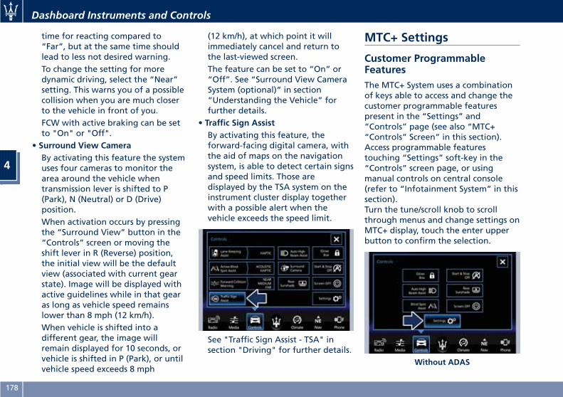
time for reacting compared to“Far”, but at the same time shouldlead to less not desired warning.To change the setting for moredynamic driving, select the “Near”setting. This warns you of a possiblecollision when you are much closerto the vehicle in front of you.FCW with active braking can be setto "On" or "Off".
• Surround View CameraBy activating this feature the systemuses four cameras to monitor thearea around the vehicle whentransmission lever is shifted to P(Park), N (Neutral) or D (Drive)position.When activation occurs by pressingthe “Surround View” button in the“Controls” screen or moving theshift lever in R (Reverse) position,the initial view will be the defaultview (associated with current gearstate). Image will be displayed withactive guidelines while in that gearas long as vehicle speed remainslower than 8 mph (12 km/h).When vehicle is shifted into adifferent gear, the image willremain displayed for 10 seconds, orvehicle is shifted in P (Park), or untilvehicle speed exceeds 8 mph
(12 km/h), at which point it willimmediately cancel and return tothe last-viewed screen.The feature can be set to “On” or“Off”. See “Surround View CameraSystem (optional)” in section“Understanding the Vehicle” forfurther details.
• Traffic Sign AssistBy activating this feature, theforward-facing digital camera, withthe aid of maps on the navigationsystem, is able to detect certain signsand speed limits. Those aredisplayed by the TSA system on theinstrument cluster display togetherwith a possible alert when thevehicle exceeds the speed limit.
See "Traffic Sign Assist - TSA" insection "Driving" for further details.
MTC+ Settings
Customer ProgrammableFeaturesThe MTC+ System uses a combinationof keys able to access and change thecustomer programmable featurespresent in the “Settings” and“Controls” page (see also “MTC+“Controls” Screen” in this section).Access programmable featurestouching “Settings” soft-key in the“Controls” screen page, or usingmanual controls on central console(refer to “Infotainment System” in thissection).Turn the tune/scroll knob to scrollthrough menus and change settings onMTC+ display, touch the enter upperbutton to confirm the selection.
Without ADAS
Dashboard Instruments and Controls
4
178
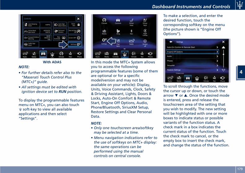
NOTE:
• For further details refer also to the“Maserati Touch Control Plus(MTC+)” guide.
• All settings must be edited withignition device set to RUN position.
To display the programmable featuresmenu on MTC+, you can also touch
soft-key to view all availableapplications and then select“Settings”.
In this mode the MTC+ System allowsyou to access the followingprogrammable features (some of themare optional or for a specificmodel/version and may not beavailable on your vehicle): Display,Units, Voice Commands, Clock, Safety& Driving Assistant, Lights, Doors &Locks, Auto-On Comfort & RemoteStart, Engine Off Options, Audio,Phone/Bluetooth, SiriusXM Setup,Restore Settings and Clear PersonalData.
NOTE:• Only one touchscreen area/softkeymay be selected at a time.
•Menu navigation indications refer tothe use of softkeys on MTC+ display:the same operations can beperformed using the manualcontrols on central console.
To make a selection, and enter thedesired function, touch thecorresponding softkey on the menu(the picture shown is “Engine OffOptions”).
To scroll through the functions, movethe cursor up or down, or touch thearrow▼ or ▲. Once the desired modeis entered, press and release thetouchscreen area of the setting thatyou wish to modify. The new settingwill be highlighted with one or moreboxes to indicate status or possiblevariants of the function status. Acheck mark in a box indicates thecurrent status of the function. Touchthe check mark to cancel, or theempty box to insert the check mark,and change the status of the function.
With ADAS
Dashboard Instruments and Controls
4
179
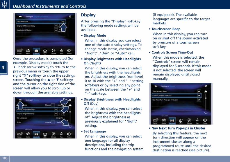
Once the procedure is completed (forexample, Display mode) touch the
back arrow softkey to return to theprevious menu or touch the upperright “X” softkey, to close the settingsscreen. Touching the ▲ or▼ softkeysand the cursor on the right side of thescreen will allow you to scroll up ordown through the available settings.
DisplayAfter pressing the “Display” soft-keythe following mode settings will beavailable.
• Display ModeWhen in this display you can selectone of the auto display settings. Tochange mode status, checkmarked"Night", “Day” or “Auto” cell.
• Display Brightness with HeadlightsOn (Night)When in this display, you can selectthe brightness with the headlightson. Adjust the brightness from level0 to 10 with the “+” and “–” settingsoft-keys or by selecting any pointon the scale between the “+” and“–” soft-keys.
• Display Brightness with HeadlightsOff (Day)When in this display, you can selectthe brightness with the headlightsoff. Adjust the brightness aspreviously explained for "Night"setting.
• Set LanguageWhen in this display, you can selectone language for all displaydescriptions, including the tripfunctions and the navigation system
(if equipped). The availablelanguages are specific to the targetmarkets.
• Touchscreen BeepWhen in this display, you can turnon or shut off the sound activatedby pressure of a touchscreensoft-key.
• Controls Screen Time-OutWhen this mode is selected, the“Controls” screen will remaindisplayed for 5 seconds. If this modeis not selected, the screen willremain displayed until closedmanually.
• Nav Next Turn Pop-ups in ClusterBy selecting this feature, the nextturn direction will appear on theinstrument cluster along aprogrammed route until the desireddestination is reached (see picture).
Dashboard Instruments and Controls
4
180
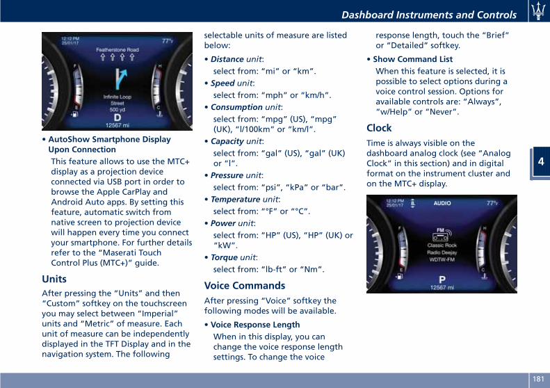
• AutoShow Smartphone DisplayUpon ConnectionThis feature allows to use the MTC+display as a projection deviceconnected via USB port in order tobrowse the Apple CarPlay andAndroid Auto apps. By setting thisfeature, automatic switch fromnative screen to projection devicewill happen every time you connectyour smartphone. For further detailsrefer to the “Maserati TouchControl Plus (MTC+)” guide.
UnitsAfter pressing the “Units” and then“Custom” softkey on the touchscreenyou may select between “Imperial”units and “Metric” of measure. Eachunit of measure can be independentlydisplayed in the TFT Display and in thenavigation system. The following
selectable units of measure are listedbelow:
• Distance unit:select from: “mi” or “km”.
• Speed unit:select from: “mph” or “km/h”.
• Consumption unit:select from: “mpg” (US), “mpg”(UK), “l/100km” or “km/l”.
• Capacity unit:select from: “gal” (US), “gal” (UK)or “l”.
• Pressure unit:select from: “psi”, “kPa” or “bar”.
• Temperature unit:select from: “°F” or “°C”.
• Power unit:select from: “HP” (US), “HP” (UK) or“kW”.
• Torque unit:select from: “lb-ft” or “Nm”.
Voice CommandsAfter pressing “Voice” softkey thefollowing modes will be available.
• Voice Response LengthWhen in this display, you canchange the voice response lengthsettings. To change the voice
response length, touch the “Brief”or “Detailed” softkey.
• Show Command ListWhen this feature is selected, it ispossible to select options during avoice control session. Options foravailable controls are: “Always”,“w/Help” or “Never”.
ClockTime is always visible on thedashboard analog clock (see “AnalogClock” in this section) and in digitalformat on the instrument cluster andon the MTC+ display.
Dashboard Instruments and Controls
4
181
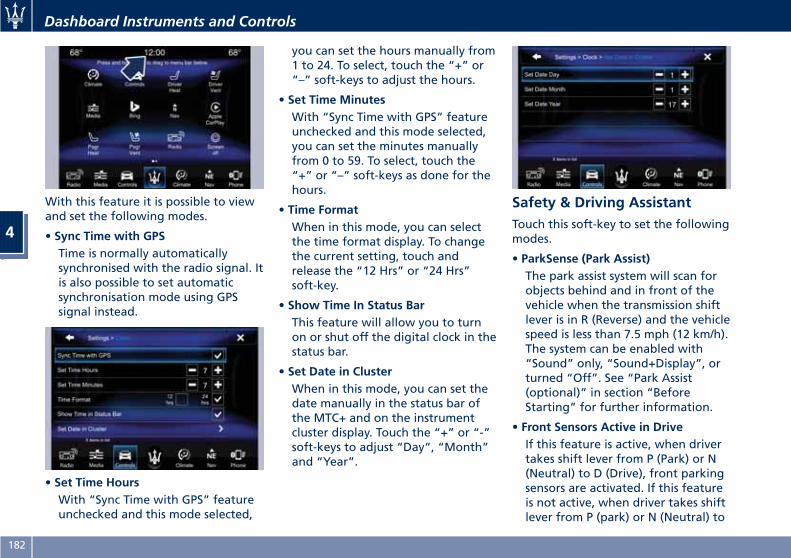
With this feature it is possible to viewand set the following modes.
• Sync Time with GPSTime is normally automaticallysynchronised with the radio signal. Itis also possible to set automaticsynchronisation mode using GPSsignal instead.
• Set Time HoursWith “Sync Time with GPS” featureunchecked and this mode selected,
you can set the hours manually from1 to 24. To select, touch the “+” or“–” soft-keys to adjust the hours.
• Set Time MinutesWith “Sync Time with GPS” featureunchecked and this mode selected,you can set the minutes manuallyfrom 0 to 59. To select, touch the“+” or “–” soft-keys as done for thehours.
• Time FormatWhen in this mode, you can selectthe time format display. To changethe current setting, touch andrelease the “12 Hrs” or “24 Hrs”soft-key.
• Show Time In Status BarThis feature will allow you to turnon or shut off the digital clock in thestatus bar.
• Set Date in ClusterWhen in this mode, you can set thedate manually in the status bar ofthe MTC+ and on the instrumentcluster display. Touch the “+” or “-”soft-keys to adjust “Day”, “Month”and “Year”.
Safety & Driving AssistantTouch this soft-key to set the followingmodes.
• ParkSense (Park Assist)The park assist system will scan forobjects behind and in front of thevehicle when the transmission shiftlever is in R (Reverse) and the vehiclespeed is less than 7.5 mph (12 km/h).The system can be enabled with“Sound” only, “Sound+Display”, orturned “Off”. See “Park Assist(optional)” in section “BeforeStarting” for further information.
• Front Sensors Active in DriveIf this feature is active, when drivertakes shift lever from P (Park) or N(Neutral) to D (Drive), front parkingsensors are activated. If this featureis not active, when driver takes shiftlever from P (park) or N (Neutral) to
Dashboard Instruments and Controls
4
182
D (Driver), front parking sensors areNOT activated.
• Front ParkSense VolumeWhen this feature is selected, thechime volume of front park assistsensors can be set to “Low”,“Medium” or “High” level.“Medium” is the default setting.The system will retain its last knownconfiguration state through ignitioncycles.
• Rear ParkSense VolumeWhen this feature is selected, thechime volume of rear park assistsensors can be set to “Low”,“Medium” or “High” level.“Medium” is the default setting.The system will retain its last knownconfiguration state through ignitioncycles.
• Tilt Side Mirrors In ReverseBy selecting this feature the outsideside-view mirrors will tilt downwardwhen the ignition is in RUN positionand the transmission shift lever is inR (Reverse) position. The mirrors willmove back to their previousposition when the transmission isshifted out of R (Reverse). Thefeature can be set to “On” or “Off”.
• Auto Folding Side MirrorsBy selecting this feature the powerexternal mirrors will automaticallyfold alfter a lock door request,performed by key fob RKEtransmitter or by the “PassiveEntry” system.Power external mirrors willautomatically unfold once theignition device is in ACC or RUNposition, only if the last foldmovement has been automatic.If the mirrors were manually foldedby the switch on the driver's doorpanel, before a lock action, they willneed to be manually unfold toreactivate the automatic behave.
• ParkView Backup Camera DelayBy selecting this feature, when theshift lever is moved out of R(Reverse), the rear view image withdynamic grid lines will be displayedfor up to 10 seconds after shiftingunless the forward vehicle speedexceeds 8 mph (12 km/h), or thetransmission is shifted into P (Park)or the ignition device is switched tothe OFF position. The feature can beset to “On” or “Off”.
• Rain Sensing Auto WipersBy selecting this feature, the system
will automatically activate thewindshield wipers if it sensesmoisture on the windshield. Thefeature can be set to “On” or “Off”.
• Hill Start AssistThis feature allows you to disablethe HSA system. The feature can beset to “On” or “Off”. See “Brakeand Stability Control System” insection “Driving” for further details.
LightsPress the “Lights” soft-key to set thefollowing modes.
• Headlight Off DelayBy selecting this feature, the drivercan choose to have the headlightoff or lit for 30, 60, or 90 secondswhen the engine is shut off. Tochange the current headlight offdelay status, touch and release the“0”, “30”, “60” or “90” soft-key toselect the desired time range.
Dashboard Instruments and Controls
4
183
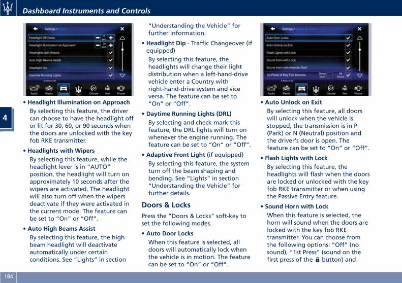
• Headlight Illumination on ApproachBy selecting this feature, the drivercan choose to have the headlight offor lit for 30, 60, or 90 seconds whenthe doors are unlocked with the keyfob RKE transmitter.
• Headlights with WipersBy selecting this feature, while theheadlight lever is in “AUTO”position, the headlight will turn onapproximately 10 seconds after thewipers are activated. The headlightwill also turn off when the wipersdeactivate if they were activated inthe current mode. The feature canbe set to “On” or “Off”.
• Auto High Beams AssistBy selecting this feature, the highbeam headlight will deactivateautomatically under certainconditions. See “Lights” in section
“Understanding the Vehicle” forfurther information.
• Headlight Dip - Traffic Changeover (ifequipped)By selecting this feature, theheadlights will change their lightdistribution when a left-hand-drivevehicle enter a Country withright-hand-drive system and viceversa. The feature can be set to“On” or “Off”.
• Daytime Running Lights (DRL)By selecting and check-mark thisfeature, the DRL lights will turn onwhenever the engine running. Thefeature can be set to “On” or “Off”.
• Adaptive Front Light (if equipped)By selecting this feature, the systemturn off the beam shaping andbending. See “Lights” in section“Understanding the Vehicle” forfurther details.
Doors & LocksPress the “Doors & Locks” soft-key toset the following modes.
• Auto Door LocksWhen this feature is selected, alldoors will automatically lock whenthe vehicle is in motion. The featurecan be set to “On” or “Off”.
• Auto Unlock on ExitBy selecting this feature, all doorswill unlock when the vehicle isstopped, the transmission is in P(Park) or N (Neutral) position andthe driver's door is open. Thefeature can be set to “On” or “Off”.
• Flash Lights with LockBy selecting this feature, theheadlights will flash when the doorsare locked or unlocked with the keyfob RKE transmitter or when usingthe Passive Entry feature.
• Sound Horn with LockWhen this feature is selected, thehorn will sound when the doors arelocked with the key fob RKEtransmitter. You can choose fromthe following options: “Off” (nosound), “1st Press” (sound on thefirst press of the button) and
Dashboard Instruments and Controls
4
184
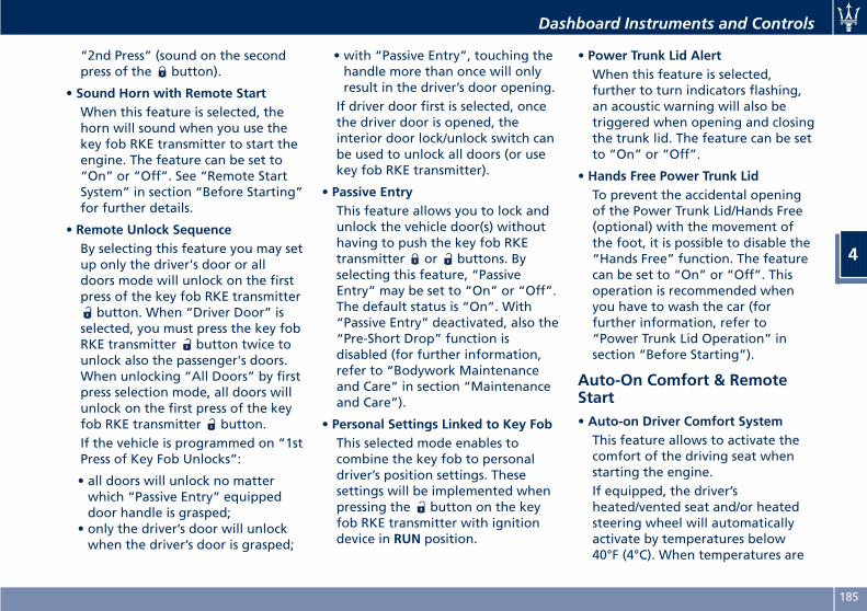
“2nd Press” (sound on the secondpress of the button).
• Sound Horn with Remote StartWhen this feature is selected, thehorn will sound when you use thekey fob RKE transmitter to start theengine. The feature can be set to“On” or “Off”. See “Remote StartSystem” in section “Before Starting”for further details.
• Remote Unlock SequenceBy selecting this feature you may setup only the driver's door or alldoors mode will unlock on the firstpress of the key fob RKE transmitter
button. When “Driver Door” isselected, you must press the key fobRKE transmitter button twice tounlock also the passenger's doors.When unlocking “All Doors” by firstpress selection mode, all doors willunlock on the first press of the keyfob RKE transmitter button.If the vehicle is programmed on “1stPress of Key Fob Unlocks”:
• all doors will unlock no matterwhich “Passive Entry” equippeddoor handle is grasped;
• only the driver’s door will unlockwhen the driver’s door is grasped;
• with “Passive Entry”, touching thehandle more than once will onlyresult in the driver’s door opening.If driver door first is selected, oncethe driver door is opened, theinterior door lock/unlock switch canbe used to unlock all doors (or usekey fob RKE transmitter).
• Passive EntryThis feature allows you to lock andunlock the vehicle door(s) withouthaving to push the key fob RKEtransmitter or buttons. Byselecting this feature, “PassiveEntry” may be set to “On” or “Off”.The default status is “On”. With“Passive Entry” deactivated, also the“Pre-Short Drop” function isdisabled (for further information,refer to “Bodywork Maintenanceand Care” in section “Maintenanceand Care”).
• Personal Settings Linked to Key FobThis selected mode enables tocombine the key fob to personaldriver’s position settings. Thesesettings will be implemented whenpressing the button on the keyfob RKE transmitter with ignitiondevice in RUN position.
• Power Trunk Lid AlertWhen this feature is selected,further to turn indicators flashing,an acoustic warning will also betriggered when opening and closingthe trunk lid. The feature can be setto “On” or “Off”.
• Hands Free Power Trunk LidTo prevent the accidental openingof the Power Trunk Lid/Hands Free(optional) with the movement ofthe foot, it is possible to disable the“Hands Free” function. The featurecan be set to “On” or “Off”. Thisoperation is recommended whenyou have to wash the car (forfurther information, refer to“Power Trunk Lid Operation” insection “Before Starting”).
Auto-On Comfort & RemoteStart• Auto-on Driver Comfort SystemThis feature allows to activate thecomfort of the driving seat whenstarting the engine.If equipped, the driver’sheated/vented seat and/or heatedsteering wheel will automaticallyactivate by temperatures below40°F (4°C). When temperatures are
Dashboard Instruments and Controls
4
185
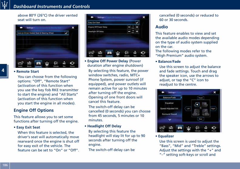
above 80°F (26°C) the driver ventedseat will turn on.
• Remote StartYou can choose from the followingoptions: “Off”, “Remote Start”(activation of this function whenyou use the key fob RKE transmitterto start the engine) and “All Starts”(activation of this function whenyou start the engine in all modes).
Engine Off OptionsThis feature allows you to set somefunctions after turning off the engine.
• Easy Exit SeatWhen this feature is selected, thedriver's seat will automatically moverearward once the engine is shut offfor easy exit of the vehicle. Thefeature can be set to “On” or “Off”.
• Engine Off Power Delay (Powerduration after engine shutdown)By selecting this feature, the powerwindow switches, radio, MTC+Phone System, power sunroof (ifequipped), and power outlets willremain active for up to 10 minutesafter turning off the engine.Opening of one front doors willcancel this feature.The switch-off delay can becancelled (0 seconds) you can choosefrom 45 seconds, 5 minutes or 10minutes.
• Headlight Off DelayBy selecting this feature theheadlight will stay lit for up to 90seconds after turning off theengine.The switch-off delay can be
cancelled (0 seconds) or reduced to60 or 30 seconds.
AudioThis feature enables to view and setthe available audio modes dependingon the type of audio system suppliedon the car.The following modes refer to the“High Premium” audio system.
• Balance/FadeUse this screen to adjust the balanceand fade settings. Touch and dragthe speaker icon, use the arrows toadjust, or tap the “C” icon toreadjust to the centre.
• EqualizerUse this screen is used to adjust the“Bass”, “Mid” and “Treble” settings.Adjust the settings with the “+” and“–” setting soft-keys or scroll and
Dashboard Instruments and Controls
4
186
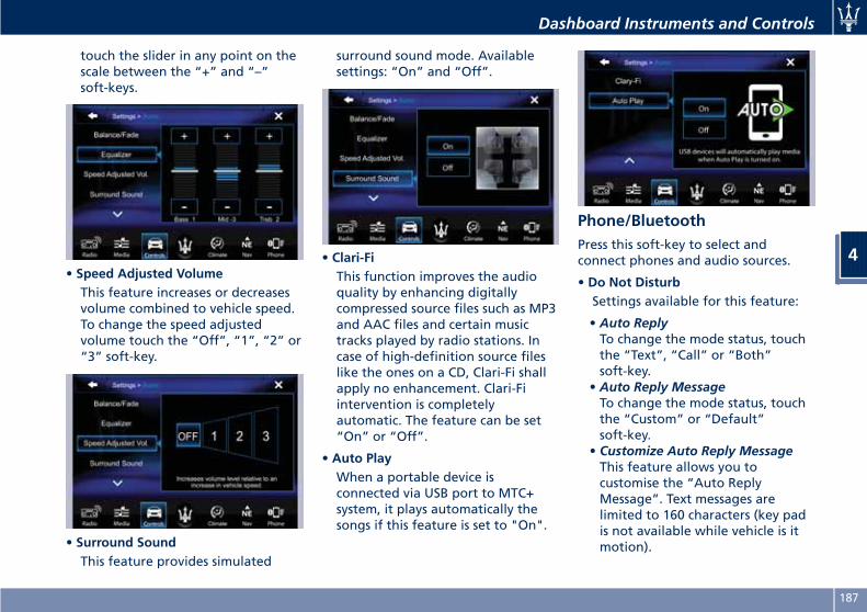
touch the slider in any point on thescale between the “+” and “–”soft-keys.
• Speed Adjusted VolumeThis feature increases or decreasesvolume combined to vehicle speed.To change the speed adjustedvolume touch the “Off”, “1”, “2” or“3” soft-key.
• Surround SoundThis feature provides simulated
surround sound mode. Availablesettings: “On” and “Off”.
• Clari-FiThis function improves the audioquality by enhancing digitallycompressed source files such as MP3and AAC files and certain musictracks played by radio stations. Incase of high-definition source fileslike the ones on a CD, Clari-Fi shallapply no enhancement. Clari-Fiintervention is completelyautomatic. The feature can be set“On” or “Off”.
• Auto PlayWhen a portable device isconnected via USB port to MTC+system, it plays automatically thesongs if this feature is set to "On".
Phone/BluetoothPress this soft-key to select andconnect phones and audio sources.
• Do Not DisturbSettings available for this feature:
• Auto ReplyTo change the mode status, touchthe “Text”, “Call” or “Both”soft-key.
• Auto Reply MessageTo change the mode status, touchthe “Custom” or “Default”soft-key.
• Customize Auto Reply MessageThis feature allows you tocustomise the “Auto ReplyMessage”. Text messages arelimited to 160 characters (key padis not available while vehicle is itmotion).
Dashboard Instruments and Controls
4
187
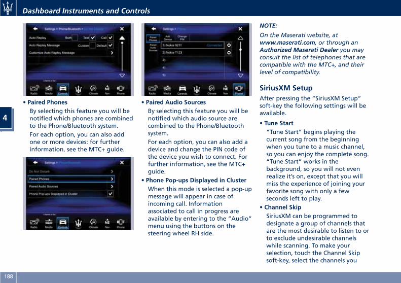
• Paired PhonesBy selecting this feature you will benotified which phones are combinedto the Phone/Bluetooth system.For each option, you can also addone or more devices: for furtherinformation, see the MTC+ guide.
• Paired Audio SourcesBy selecting this feature you will benotified which audio source arecombined to the Phone/Bluetoothsystem.For each option, you can also add adevice and change the PIN code ofthe device you wish to connect. Forfurther information, see the MTC+guide.
• Phone Pop-ups Displayed in ClusterWhen this mode is selected a pop-upmessage will appear in case ofincoming call. Informationassociated to call in progress areavailable by entering to the “Audio”menu using the buttons on thesteering wheel RH side.
NOTE:
On the Maserati website, atwww.maserati.com, or through anAuthorized Maserati Dealer you mayconsult the list of telephones that arecompatible with the MTC+, and theirlevel of compatibility.
SiriusXM SetupAfter pressing the “SiriusXM Setup”soft-key the following settings will beavailable.
• Tune Start“Tune Start” begins playing thecurrent song from the beginningwhen you tune to a music channel,so you can enjoy the complete song.“Tune Start” works in thebackground, so you will not evenrealize it’s on, except that you willmiss the experience of joining yourfavorite song with only a fewseconds left to play.
• Channel SkipSiriusXM can be programmed todesignate a group of channels thatare the most desirable to listen to orto exclude undesirable channelswhile scanning. To make yourselection, touch the Channel Skipsoft-key, select the channels you
Dashboard Instruments and Controls
4
188
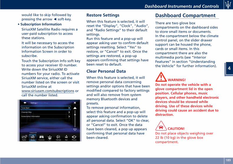
would like to skip followed bypressing the arrow◄ soft-key.
• Subscription InformationSiriusXM Satellite Radio requires auser-paid subscription to accessthese stations.It will be necessary to access theinformation on the SubscriptionInformation Screen in order tosubscribe.Touch the Subscription Info soft keyto access your receiver ID number.Write down the SiriusXM IDnumbers for your radio. To activateSiriusXM service, either call thenumber listed on the screen or visitSiriusXM online atwww.siriusxm.com/subscriptions orcall the number listed.
Restore SettingsWhen this feature is selected, it willreset the “Display”, “Clock”, “Audio”,and “Radio Settings” to their defaultsettings.Run this feature and a pop-up willappear asking user to confirm defaultsettings resetting. Select “Yes” torestore, or “Cancel” to exit. Once thesettings are restored, a pop-upappears confirming that settings havebeen reset to default.
Clear Personal DataWhen this feature is selected, it willremove personal data concerningsettings and/or options that have beenmodified compared to factory settingsand will also remove from systemmemory Bluetooth devices andpresets.To remove personal information,select this feature and a pop-up willappear asking confirmation to deleteall personal data. Select “OK” to clear,or “Cancel” to exit. Once the datahave been cleared, a pop up appearsconfirming that personal data havebeen cleared.
Dashboard CompartmentThere are two glove boxcompartments on the dashboard sidesto store small items or documents.In the compartment below the climatecontrol panel, on the slider drawersupport can be housed the phone,cards or small items. In thiscompartment there are also themultimedia ports (see “InteriorFeatures” in section “Understandingthe Vehicle” for further information).
WARNING!Do not operate the vehicle with aglove compartment lid in the openposition. Cellular phones, musicplayers, and other handheld electronicdevices should be stowed whiledriving. Use of these devices whiledriving could cause an accident due todistraction.
CAUTION!Do not place objects weighing over22 lb (10 kg) in the glove boxcompartment.
Dashboard Instruments and Controls
4
189
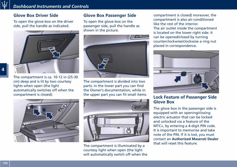
Glove Box Driver SideTo open the glove box on the driverside, pull the handle as indicated.
The compartment is ca. 10-12 in (25-30cm) deep and is lit by two courtesylights when open (the lightautomatically switches off when thecompartment is closed).
Glove Box Passenger SideTo open the glove box on thepassenger side, pull the handle asshown in the picture.
The compartment is divided into twoparts: in the lower part you can findthe Owner’s documentation, while inthe upper part you can fit small items.
The compartment is illuminated by acourtesy light when open (the lightwill automatically switch off when the
compartment is closed) moreover, thecompartment is also air-conditionedlike the rest of the interior.The air outlet inside the compartmentis located on the lower right side: itcan be opened/closed by turningcounterclockwise/clockwise a ring nutplaced in correspondence.
Lock Feature of Passenger SideGlove BoxThe glove box in the passenger side isequipped with an opening/closingelectric actuator that can be lockedand unlocked via a feature of theMTC+, by entering a 4-digit PIN code.It is important to memorize and takenote of the PIN. If it is lost, you mustcontact an Authorized Maserati Dealerthat will reset this feature.
Dashboard Instruments and Controls
4
190
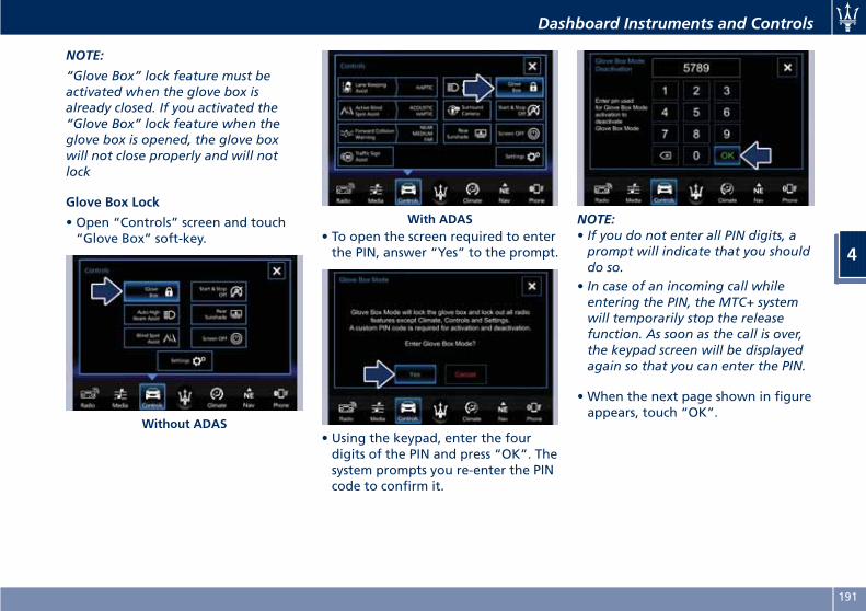
NOTE:
“Glove Box” lock feature must beactivated when the glove box isalready closed. If you activated the“Glove Box” lock feature when theglove box is opened, the glove boxwill not close properly and will notlock
Glove Box Lock
• Open “Controls” screen and touch“Glove Box” soft-key. • To open the screen required to enter
the PIN, answer “Yes” to the prompt.
• Using the keypad, enter the fourdigits of the PIN and press “OK”. Thesystem prompts you re-enter the PINcode to confirm it.
NOTE:• If you do not enter all PIN digits, aprompt will indicate that you shoulddo so.
• In case of an incoming call whileentering the PIN, the MTC+ systemwill temporarily stop the releasefunction. As soon as the call is over,the keypad screen will be displayedagain so that you can enter the PIN.
• When the next page shown in figureappears, touch “OK”.
Without ADAS
With ADAS
Dashboard Instruments and Controls
4
191
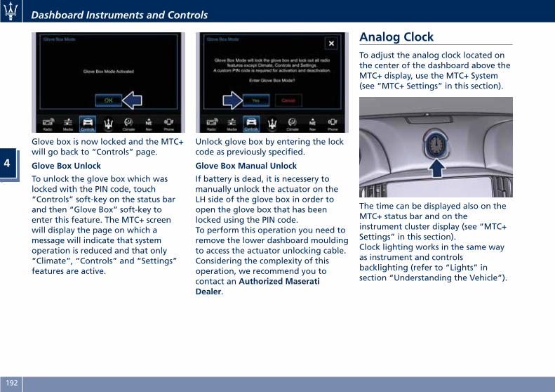
Glove box is now locked and the MTC+will go back to “Controls” page.
Glove Box Unlock
To unlock the glove box which waslocked with the PIN code, touch“Controls” soft-key on the status barand then “Glove Box” soft-key toenter this feature. The MTC+ screenwill display the page on which amessage will indicate that systemoperation is reduced and that only“Climate”, “Controls” and “Settings”features are active.
Unlock glove box by entering the lockcode as previously specified.
Glove Box Manual Unlock
If battery is dead, it is necessery tomanually unlock the actuator on theLH side of the glove box in order toopen the glove box that has beenlocked using the PIN code.To perform this operation you need toremove the lower dashboard mouldingto access the actuator unlocking cable.Considering the complexity of thisoperation, we recommend you tocontact an Authorized MaseratiDealer.
Analog ClockTo adjust the analog clock located onthe center of the dashboard above theMTC+ display, use the MTC+ System(see “MTC+ Settings” in this section).
The time can be displayed also on theMTC+ status bar and on theinstrument cluster display (see “MTC+Settings” in this section).Clock lighting works in the same wayas instrument and controlsbacklighting (refer to “Lights” insection “Understanding the Vehicle”).
Dashboard Instruments and Controls
4
192
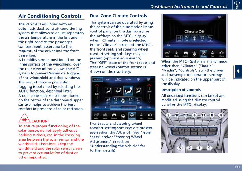
Air Conditioning ControlsThe vehicle is equipped with anautomatic dual-zone air conditioningsystem that allows to adjust separatelythe air temperature in the left and inthe right zone of the passengercompartment, according to therequests of the driver and the frontpassenger.A humidity sensor, positioned on theinner surface of the windshield, overthe rear view mirror, allows the A/Csystem to prevent/eliminate foggingof the windshield and side windows.The best efficacy in preventingfogging is obtained by selecting theAUTO function, described later.A dual zone solar sensor, positionedon the center of the dashboard uppersurface, helps to achieve the bestcomfort in presence of solar radiation.
CAUTION!To ensure proper functioning of thesolar sensor, do not apply adhesiveparking stickers, etc. in the checkingarea between the solar sensor and thewindshield. Therefore, keep thewindshield and the solar sensor cleanto prevent accumulation of dust orother impurities.
Dual Zone Climate ControlsThis system can be operated by usingthe controls of the automatic climatecontrol panel on the dashboard, orthe softkeys on the MTC+ displaywhen “Climate” mode is selected.In the "Climate" screen of the MTC+,the front seats and steering wheelcomfort setting soft-keys may bepresent (optional equipments).The “OFF” state of the front seats andsteering wheel comfort setting isshown on their soft-key.
Front seats and steering wheelcomfort setting soft-keys are presenteven when the A/C is off (see "FrontSeats" and/or "Steering WheelAdjustment" in section"Understanding the Vehicle" forfurther details).
When the MTC+ System is in any modeother than “Climate” (“Radio”,“Media”, “Controls”, etc.) the driverand passenger temperature settingswill be indicated on the upper part ofthe display.
Description of Controls
All described functions can be set andmodified using the climate controlpanel or the MTC+ display.
Dashboard Instruments and Controls
4
193
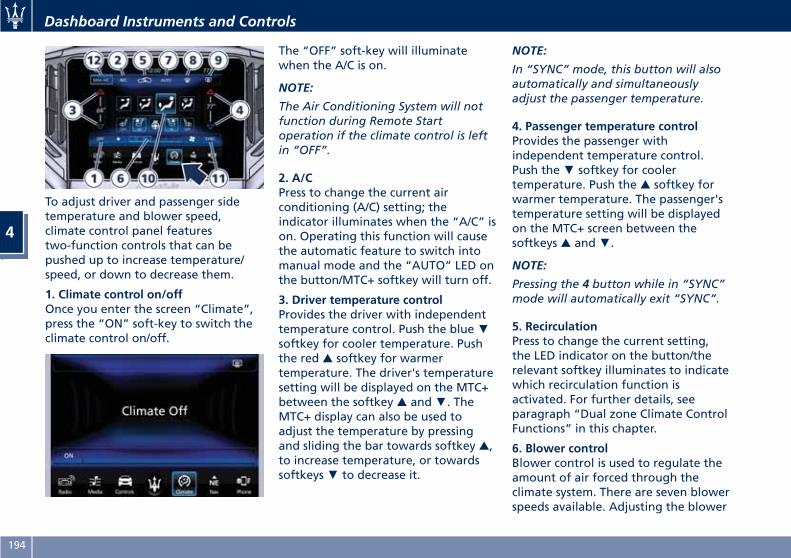
To adjust driver and passenger sidetemperature and blower speed,climate control panel featurestwo-function controls that can bepushed up to increase temperature/speed, or down to decrease them.
1. Climate control on/offOnce you enter the screen “Climate”,press the “ON” soft-key to switch theclimate control on/off.
The “OFF” soft-key will illuminatewhen the A/C is on.
NOTE:
The Air Conditioning System will notfunction during Remote Startoperation if the climate control is leftin “OFF”.
2. A/CPress to change the current airconditioning (A/C) setting; theindicator illuminates when the “A/C” ison. Operating this function will causethe automatic feature to switch intomanual mode and the “AUTO” LED onthe button/MTC+ softkey will turn off.
3. Driver temperature controlProvides the driver with independenttemperature control. Push the blue▼softkey for cooler temperature. Pushthe red ▲ softkey for warmertemperature. The driver's temperaturesetting will be displayed on the MTC+between the softkey ▲ and▼. TheMTC+ display can also be used toadjust the temperature by pressingand sliding the bar towards softkey ▲,to increase temperature, or towardssoftkeys▼ to decrease it.
NOTE:
In “SYNC” mode, this button will alsoautomatically and simultaneouslyadjust the passenger temperature.
4. Passenger temperature controlProvides the passenger withindependent temperature control.Push the▼ softkey for coolertemperature. Push the ▲ softkey forwarmer temperature. The passenger'stemperature setting will be displayedon the MTC+ screen between thesoftkeys ▲ and▼.
NOTE:
Pressing the 4 button while in “SYNC”mode will automatically exit “SYNC”.
5. RecirculationPress to change the current setting,the LED indicator on the button/therelevant softkey illuminates to indicatewhich recirculation function isactivated. For further details, seeparagraph “Dual zone Climate ControlFunctions” in this chapter.
6. Blower controlBlower control is used to regulate theamount of air forced through theclimate system. There are seven blowerspeeds available. Adjusting the blower
Dashboard Instruments and Controls
4
194
will cause automatic mode to switchto manual.On the climate control panel, push therocker switch up to increase blowerspeed. Push the rocker switch down todecrease blower speed. Pushing downthe rocker switch when set blower isat the first speed, causes the A/Csystem shutdown (OFF condition).On the MTC+ display, touch the smallicon of the blower to decrease thespeed, or the big icon to increase it.Between the two icons, bars willappear to show the number of thecorresponding selected speed.The blower can also be activated/regulated by touching the barsbetween the two blower icons.
7. AUTOThis function automatically controlsthe interior temperature by adjustingthe air flow rate and the airdistribution. Press “AUTO” to switchthe ATC between manual andautomatic mode. The LED on thebutton/the “AUTO” softkeyilluminates when the “AUTO”function is activated. See “AutomaticTemperature Control (ATC)” in thischapter for more information.
8. FAST defrosting/defoggingPress the button/MTC+ softkey toswitch the airflow setting to thewindshield and the front sidewindows to get a quick defrosting/defogging. The LED on thebutton/MTC+ softkey illuminateswhen this feature is activated.Operating this function will cause theATC to switch into manual mode: sothe “AUTO” LED/MTC+ softkey willturn off; the fifth blower speed will beautomatically selected, unless theblower is already set to a higherspeed. If this function is turned off theclimate system will return to theprevious setting.
9. REAR defrosting/defoggingPress the button/MTC+ softkey toturn on the rear window defrosterand the heated outside mirrors. A LEDindicator/MTC+ softkey will illuminatewhen the rear window defroster andthe heated outside mirrors are on.The rear window defroster and theheated outside mirrors automaticallyturn off after 10 minutes.
CAUTION!Failure to observe the followingcautions may cause damage to the
rear windows defroster:
• Use care when washing the inside ofthe rear window. Do not useabrasive window cleaners on theinterior surface of the window. Use asoft cloth and a mild washingsolution, wiping parallel to theheating elements. Labels can bepeeled off after soaking with warmwater.
• Do not use scrapers, sharpinstruments, or abrasive windowcleaners on the interior surface ofthe window.
• Keep all objects inside the vehicle ata safe distance from the window.
10. Air flow distribution modesThe airflow distribution mode can beadjusted so air comes from thedashboard vents, floor vents,defog/defrost vents.The display contains the relevantsoftkeys used to set these modes. Theclimate control panel features abutton : press it several times toselect and set the required airflowdistribution mode.
Available settings are as follows:• “Dashboard” modeAir flows in from the fouradjustable vents of the dashboard
Dashboard Instruments and Controls
4
195
and the two positioned at the rearof the central console. Each of thesevents can be singly adjusted. The airgrids or vanes of the vents can bemoved to adjust air flow direction. Asetting wheel, placed near eachvent, allows to regulate or close theair flow.
• “Bi-Level” modeAir comes from the dashboard vents,the central console adjustable ventsand the fixed floor vents. A smallportion of the airflow is directedthrough the defrost/defog vents.
NOTE:
Bi-Level mode is designed to havemore fresh air out of the dashboardvents and rear part of the centralconsole vents and warmer air from thefloor vents.
• “Floor” modeAir comes from the floor vents. Asmall portion of the airflow isdirected through the defrost/defogvents.
• “Mix” modeAir comes from the defrost/defogvents and from the floor vents. Thismode is recommended for cold
climates, to improve comfort andprevent fogging.
11. “SYNC” modePress the “SYNC” softkey on the MTC+to switch the Sync feature on/off. The“SYNC” indicator illuminates when thisfeature is selected. This function isused to synchronize the passengertemperature setting with the drivertemperature setting.Changing the passenger temperaturesetting while in “SYNC” willautomatically exit this feature.
12. MAX A/CBy pressing the “MAX A/C”button/MTC+ softkey, the systemautomatically switches to get themaximum cold air flow.
Dual Zone Climate ControlFunctionsAir Conditioning (A/C)The “A/C” button allows to manuallyactivate or deactivate the airconditioning system. When the airconditioning system is turned on, cooldehumidified air will flow through thevents into the cabin. For improved fueleconomy, press the “A/C” button toturn off the air conditioning andmanually adjust the blower andairflow mode settings.
When the “A/C” and “AUTO” areswitched off it is not possible to haveair at a lower temperature than theoutside.
Recirculation and Air QualitySensor (AQS)When outside air contains smoke,odours, or high humidity, or if rapidcooling is desired, you may wish torecirculate interior air by pressing therecirculation control button to activatethe two different functionalities.The recirculation function, that allowsto open/close the A/C air inlet byoperating the relevant button on theclimate control panel/MTC+ softkey, isintegrated with the Air Quality Sensor.This sensor, positioned upstream of theA/C filter, in front of the air intake ofthe A/C system, detects the presence ofpolluting substances and submits anelectric signal to the A/C control unit,that closes the intake of the externalair by activating the air recirculation.The recirculation button/MTC+ softkeycan therefore enable three operatingmodes, switchable in sequence.Starting from the outside aircondition, in which the external air isaspirated by the A/C system andtreated to be introduced into thepassenger compartment, subsequent
Dashboard Instruments and Controls
4
196
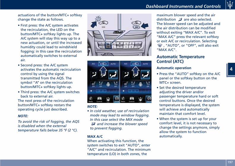
actuations of the button/MTC+ softkeychange the state as follows.
• First press: the A/C system activatesthe recirculation, the LED on thebutton/MTC+ softkey lights up. TheA/C system will stay this way up to anew actuation, or until the increasedhumidity could lead to windshieldfogging: in this case the recirculationautomatically switches to externalair.
• Second press: the A/C systemactivates the automatic recirculationcontrol by using the signaltransmitted from the AQS. Thesymbol ‘’A’’ on the recirculationbutton/MTC+ softkey lights up.
• Third press: the A/C system switchesback to external air.
The next press of the recirculationbutton/MTC+ softkey restars theoperating cycle just described.
NOTE:
To avoid the risk of fogging, the AQSis disabled when the externaltemperature falls below 35 °F (2 °C).
NOTE:• In cold weather, use of recirculationmode may lead to window fogging.In this case select the MIX mode
and increase the blower speedto prevent fogging.
MAX A/CWhen activating this function, thesystem switches to exit “AUTO”, enter“A/C” and recirculation. The minimumtemperature (LO) in both zones, the
maximum blower speed and the airdistribution are also selected.The blower speed can be adjusted andthe air distribution can be modifiedwithout exiting “MAX A/C”. To exit“MAX A/C” press the relevant softkeyor exit A/C or recirculation. Selecting
, “AUTO”, or “OFF”, will also exit“MAX A/C”.
Automatic TemperatureControl (ATC)Automatic operation
• Press the “AUTO” softkey on the A/Cpanel or the softkey button on theMTC+ screen.
• Set the desired temperatureadjusting the driver and/orpassenger temperature hard or softcontrol buttons. Once the desiredtemperature is displayed, the systemwill achieve and automaticallymaintain that comfort level.
• When the system is set up for yourcomfort level, it is not necessary tochange the settings anymore, simplyallow the system to functionautomatically.
Dashboard Instruments and Controls
4
197
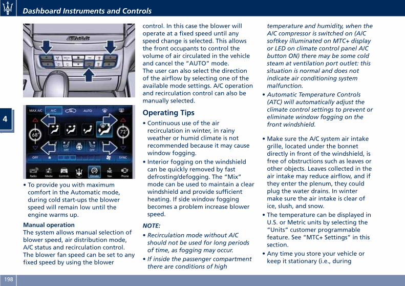
• To provide you with maximumcomfort in the Automatic mode,during cold start-ups the blowerspeed will remain low until theengine warms up.
Manual operationThe system allows manual selection ofblower speed, air distribution mode,A/C status and recirculation control.The blower fan speed can be set to anyfixed speed by using the blower
control. In this case the blower willoperate at a fixed speed until anyspeed change is selected. This allowsthe front occupants to control thevolume of air circulated in the vehicleand cancel the “AUTO” mode.The user can also select the directionof the airflow by selecting one of theavailable mode settings. A/C operationand recirculation control can also bemanually selected.
Operating Tips• Continuous use of the airrecirculation in winter, in rainyweather or humid climate is notrecommended because it may causewindow fogging.
• Interior fogging on the windshieldcan be quickly removed by fastdefrosting/defogging. The “Mix”mode can be used to maintain a clearwindshield and provide sufficientheating. If side window foggingbecomes a problem increase blowerspeed.
NOTE:
• Recirculation mode without A/Cshould not be used for long periodsof time, as fogging may occur.
• If inside the passenger compartmentthere are conditions of high
temperature and humidity, when theA/C compressor is switched on (A/Csoftkey illuminated on MTC+ displayor LED on climate control panel A/Cbutton ON) there may be some coldsteam at ventilation port outlet: thissituation is normal and does notindicate air conditioning systemmalfunction.
• Automatic Temperature Controls(ATC) will automatically adjust theclimate control settings to prevent oreliminate window fogging on thefront windshield.
• Make sure the A/C system air intakegrille, located under the bonnetdirectly in front of the windshield, isfree of obstructions such as leaves orother objects. Leaves collected in theair intake may reduce airflow, and ifthey enter the plenum, they couldplug the water drains. In wintermake sure the air intake is clear ofice, slush, and snow.
• The temperature can be displayed inU.S. or Metric units by selecting the“Units” customer programmablefeature. See “MTC+ Settings” in thissection.
• Any time you store your vehicle orkeep it stationary (i.e., during
Dashboard Instruments and Controls
4
198
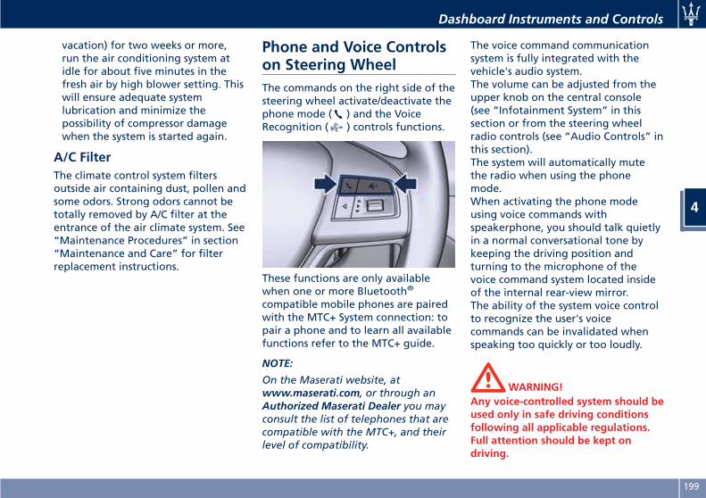
vacation) for two weeks or more,run the air conditioning system atidle for about five minutes in thefresh air by high blower setting. Thiswill ensure adequate systemlubrication and minimize thepossibility of compressor damagewhen the system is started again.
A/C FilterThe climate control system filtersoutside air containing dust, pollen andsome odors. Strong odors cannot betotally removed by A/C filter at theentrance of the air climate system. See“Maintenance Procedures” in section“Maintenance and Care” for filterreplacement instructions.
Phone and Voice Controlson Steering WheelThe commands on the right side of thesteering wheel activate/deactivate thephone mode ( ) and the VoiceRecognition ( ) controls functions.
These functions are only availablewhen one or more Bluetooth®
compatible mobile phones are pairedwith the MTC+ System connection: topair a phone and to learn all availablefunctions refer to the MTC+ guide.
NOTE:
On the Maserati website, atwww.maserati.com, or through anAuthorized Maserati Dealer you mayconsult the list of telephones that arecompatible with the MTC+, and theirlevel of compatibility.
The voice command communicationsystem is fully integrated with thevehicle's audio system.The volume can be adjusted from theupper knob on the central console(see “Infotainment System” in thissection or from the steering wheelradio controls (see “Audio Controls” inthis section).The system will automatically mutethe radio when using the phonemode.When activating the phone modeusing voice commands withspeakerphone, you should talk quietlyin a normal conversational tone bykeeping the driving position andturning to the microphone of thevoice command system located insideof the internal rear-view mirror.The ability of the system voice controlto recognize the user's voicecommands can be invalidated whenspeaking too quickly or too loudly.
WARNING!Any voice-controlled system should beused only in safe driving conditionsfollowing all applicable regulations.Full attention should be kept ondriving.
Dashboard Instruments and Controls
4
199
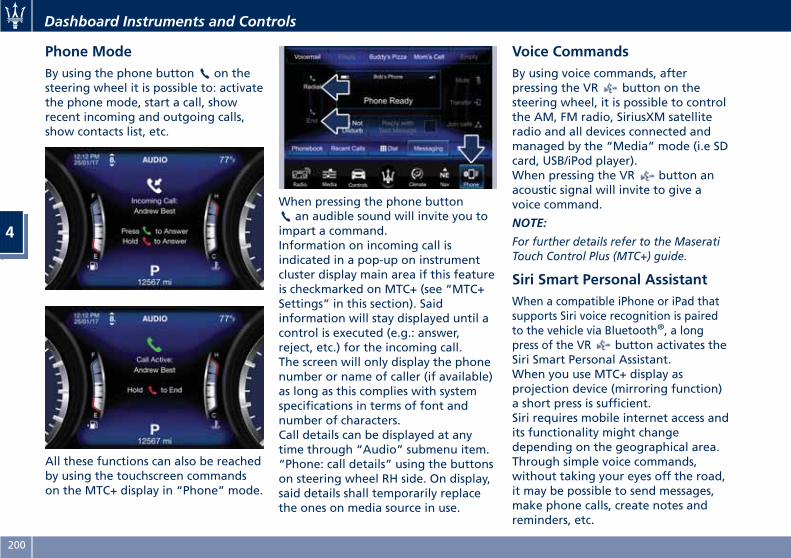
Phone ModeBy using the phone button on thesteering wheel it is possible to: activatethe phone mode, start a call, showrecent incoming and outgoing calls,show contacts list, etc.
All these functions can also be reachedby using the touchscreen commandson the MTC+ display in “Phone” mode.
When pressing the phone buttonan audible sound will invite you to
impart a command.Information on incoming call isindicated in a pop-up on instrumentcluster display main area if this featureis checkmarked on MTC+ (see “MTC+Settings” in this section). Saidinformation will stay displayed until acontrol is executed (e.g.: answer,reject, etc.) for the incoming call.The screen will only display the phonenumber or name of caller (if available)as long as this complies with systemspecifications in terms of font andnumber of characters.Call details can be displayed at anytime through “Audio” submenu item.“Phone: call details” using the buttonson steering wheel RH side. On display,said details shall temporarily replacethe ones on media source in use.
Voice CommandsBy using voice commands, afterpressing the VR button on thesteering wheel, it is possible to controlthe AM, FM radio, SiriusXM satelliteradio and all devices connected andmanaged by the “Media” mode (i.e SDcard, USB/iPod player).When pressing the VR button anacoustic signal will invite to give avoice command.
NOTE:
For further details refer to the MaseratiTouch Control Plus (MTC+) guide.
Siri Smart Personal AssistantWhen a compatible iPhone or iPad thatsupports Siri voice recognition is pairedto the vehicle via Bluetooth®, a longpress of the VR button activates theSiri Smart Personal Assistant.When you use MTC+ display asprojection device (mirroring function)a short press is sufficient.Siri requires mobile internet access andits functionality might changedepending on the geographical area.Through simple voice commands,without taking your eyes off the road,it may be possible to send messages,make phone calls, create notes andreminders, etc.
Dashboard Instruments and Controls
4
200
5 – Driving
Normal Starting of the Engine . . . . . . . . . . . . . . . . . . . . . . . . . . . . . 202Automatic Transmission . . . . . . . . . . . . . . . . . . . . . . . . . . . . . . . . . . 207All-Wheel Drive (AWD version only) . . . . . . . . . . . . . . . . . . . . . . . . . 213Drive Mode . . . . . . . . . . . . . . . . . . . . . . . . . . . . . . . . . . . . . . . . . . . 213Parking Brake . . . . . . . . . . . . . . . . . . . . . . . . . . . . . . . . . . . . . . . . . 224Parking . . . . . . . . . . . . . . . . . . . . . . . . . . . . . . . . . . . . . . . . . . . . . . 227Brake and Stability Control System . . . . . . . . . . . . . . . . . . . . . . . . . 229Using the Brakes . . . . . . . . . . . . . . . . . . . . . . . . . . . . . . . . . . . . . . . 232Use of the Engine . . . . . . . . . . . . . . . . . . . . . . . . . . . . . . . . . . . . . . 233Electronic Cruise Control . . . . . . . . . . . . . . . . . . . . . . . . . . . . . . . . . 235Adaptive Cruise Control – ACC (optional) . . . . . . . . . . . . . . . . . . . . . 239Forward Collision Warning – FCW (optional, with ACC only) . . . . . . 249Lane Keeping Assist - LKA (optional, with ACC only) . . . . . . . . . . . . 253Blind Spot Assist (without ACC) . . . . . . . . . . . . . . . . . . . . . . . . . . . . 257Active Blind Spot Assist - ABSA (optional, with ACC only) . . . . . . . . 262Highway Assist – HAS (optional, with ACC only) . . . . . . . . . . . . . . . . 266Traffic Sign Assist – TSA (optional) . . . . . . . . . . . . . . . . . . . . . . . . . . 272Tires - General Information . . . . . . . . . . . . . . . . . . . . . . . . . . . . . . . 274Tire Pressure Monitoring System (TPMS) . . . . . . . . . . . . . . . . . . . . . 280Fuel Requirements . . . . . . . . . . . . . . . . . . . . . . . . . . . . . . . . . . . . . . 285Refueling . . . . . . . . . . . . . . . . . . . . . . . . . . . . . . . . . . . . . . . . . . . . . 287Driving Conditions . . . . . . . . . . . . . . . . . . . . . . . . . . . . . . . . . . . . . . 289
201
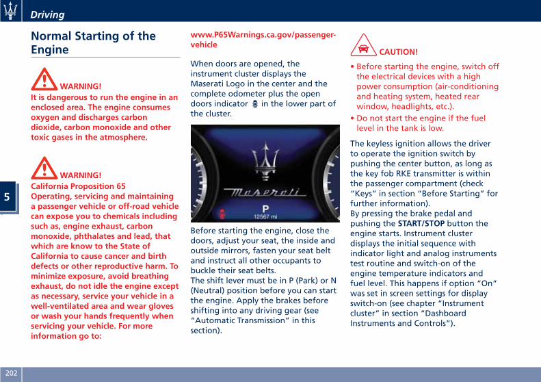
Normal Starting of theEngine
WARNING!It is dangerous to run the engine in anenclosed area. The engine consumesoxygen and discharges carbondioxide, carbon monoxide and othertoxic gases in the atmosphere.
WARNING!California Proposition 65Operating, servicing and maintaininga passenger vehicle or off-road vehiclecan expose you to chemicals includingsuch as, engine exhaust, carbonmonoxide, phthalates and lead, thatwhich are know to the State ofCalifornia to cause cancer and birthdefects or other reproductive harm. Tominimize exposure, avoid breathingexhaust, do not idle the engine exceptas necessary, service your vehicle in awell-ventilated area and wear glovesor wash your hands frequently whenservicing your vehicle. For moreinformation go to:
www.P65Warnings.ca.gov/passenger-vehicle
When doors are opened, theinstrument cluster displays theMaserati Logo in the center and thecomplete odometer plus the opendoors indicator in the lower part ofthe cluster.
Before starting the engine, close thedoors, adjust your seat, the inside andoutside mirrors, fasten your seat beltand instruct all other occupants tobuckle their seat belts.The shift lever must be in P (Park) or N(Neutral) position before you can startthe engine. Apply the brakes beforeshifting into any driving gear (see“Automatic Transmission” in thissection).
CAUTION!
• Before starting the engine, switch offthe electrical devices with a highpower consumption (air-conditioningand heating system, heated rearwindow, headlights, etc.).
• Do not start the engine if the fuellevel in the tank is low.
The keyless ignition allows the driverto operate the ignition switch bypushing the center button, as long asthe key fob RKE transmitter is withinthe passenger compartment (check“Keys” in section “Before Starting” forfurther information).By pressing the brake pedal andpushing the START/STOP button theengine starts. Instrument clusterdisplays the initial sequence withindicator light and analog instrumentstest routine and switch-on of theengine temperature indicators andfuel level. This happens if option “On”was set in screen settings for displayswitch-on (see chapter “Instrumentcluster” in section “DashboardInstruments and Controls”).
Driving
5
202
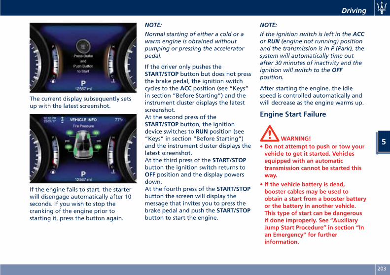
The current display subsequently setsup with the latest screenshot.
If the engine fails to start, the starterwill disengage automatically after 10seconds. If you wish to stop thecranking of the engine prior tostarting it, press the button again.
NOTE:
Normal starting of either a cold or awarm engine is obtained withoutpumping or pressing the acceleratorpedal.
If the driver only pushes theSTART/STOP button but does not pressthe brake pedal, the ignition switchcycles to the ACC position (see “Keys”in section “Before Starting”) and theinstrument cluster displays the latestscreenshot.At the second press of theSTART/STOP button, the ignitiondevice switches to RUN position (see“Keys” in section “Before Starting”)and the instrument cluster displays thelatest screenshot.At the third press of the START/STOPbutton the ignition switch returns toOFF position and the display powersdown.At the fourth press of the START/STOPbutton the screen will display themessage that invites you to press thebrake pedal and push the START/STOPbutton to start the engine.
NOTE:
If the ignition switch is left in the ACCor RUN (engine not running) positionand the transmission is in P (Park), thesystem will automatically time outafter 30 minutes of inactivity and theignition will switch to the OFFposition.
After starting the engine, the idlespeed is controlled automatically andwill decrease as the engine warms up.
Engine Start Failure
WARNING!• Do not attempt to push or tow yourvehicle to get it started. Vehiclesequipped with an automatictransmission cannot be started thisway.
• If the vehicle battery is dead,booster cables may be used toobtain a start from a booster batteryor the battery in another vehicle.This type of start can be dangerousif done improperly. See “AuxiliaryJump Start Procedure” in section “Inan Emergency” for furtherinformation.
Driving
5
203
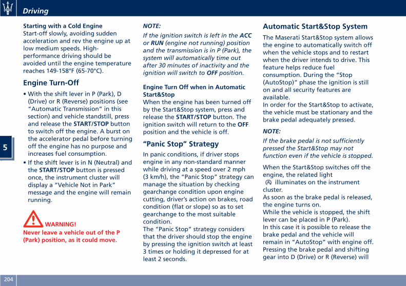
Starting with a Cold EngineStart-off slowly, avoiding suddenacceleration and rev the engine up atlow medium speeds. High-performance driving should beavoided until the engine temperaturereaches 149-158°F (65-70°C).
Engine Turn-Off• With the shift lever in P (Park), D(Drive) or R (Reverse) positions (see“Automatic Transmission” in thissection) and vehicle standstill, pressand release the START/STOP buttonto switch off the engine. A burst onthe accelerator pedal before turningoff the engine has no purpose andincreases fuel consumption.
• If the shift lever is in N (Neutral) andthe START/STOP button is pressedonce, the instrument cluster willdisplay a “Vehicle Not in Park”message and the engine will remainrunning.
WARNING!Never leave a vehicle out of the P(Park) position, as it could move.
NOTE:
If the ignition switch is left in the ACCor RUN (engine not running) positionand the transmission is in P (Park), thesystem will automatically time outafter 30 minutes of inactivity and theignition will switch to OFF position.
Engine Turn Off when in AutomaticStart&StopWhen the engine has been turned offby the Start&Stop system, press andrelease the START/STOP button. Theignition switch will return to the OFFposition and the vehicle is off.
“Panic Stop” StrategyIn panic conditions, if driver stopsengine in any non-standard mannerwhile driving at a speed over 2 mph(3 km/h), the “Panic Stop” strategy canmanage the situation by checkinggearchange condition upon enginecutting, driver’s action on brakes, roadcondition (flat or slope) so as to setgearchange to the most suitablecondition.The “Panic Stop” strategy considersthat the driver should stop the engineby pressing the ignition switch at least3 times or holding it depressed for atleast 2 seconds.
Automatic Start&Stop SystemThe Maserati Start&Stop system allowsthe engine to automatically switch offwhen the vehicle stops and to restartwhen the driver intends to drive. Thisfeature helps reduce fuelconsumption. During the “Stop(AutoStop)” phase the ignition is stillon and all security features areavailable.In order for the Start&Stop to activate,the vehicle must be stationary and thebrake pedal adequately pressed.
NOTE:
If the brake pedal is not sufficientlypressed the Start&Stop may notfunction even if the vehicle is stopped.
When the Start&Stop switches off theengine, the related light
illuminates on the instrumentcluster.As soon as the brake pedal is released,the engine turns on.While the vehicle is stopped, the shiftlever can be placed in P (Park).In this case it is possible to release thebrake pedal and the vehicle willremain in “AutoStop” with engine off.Pressing the brake pedal and shiftinggear into D (Drive) or R (Reverse) will
Driving
5
204
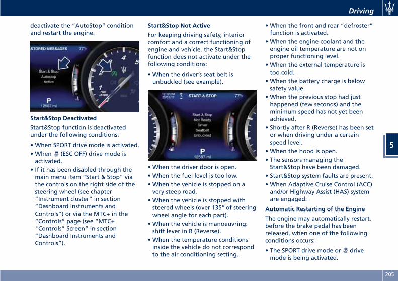
deactivate the “AutoStop” conditionand restart the engine.
Start&Stop Deactivated
Start&Stop function is deactivatedunder the following conditions:
• When SPORT drive mode is activated.• When (ESC OFF) drive mode isactivated.
• If it has been disabled through themain menu item “Start & Stop” viathe controls on the right side of thesteering wheel (see chapter“Instrument cluster” in section“Dashboard Instruments andControls”) or via the MTC+ in the“Controls” page (see “MTC+"Controls" Screen” in section“Dashboard Instruments andControls”).
Start&Stop Not Active
For keeping driving safety, interiorcomfort and a correct functioning ofengine and vehicle, the Start&Stopfunction does not activate under thefollowing conditions:
• When the driver’s seat belt isunbuckled (see example).
• When the driver door is open.• When the fuel level is too low.• When the vehicle is stopped on avery steep road.
• When the vehicle is stopped withsteered wheels (over 135° of steeringwheel angle for each part).
• When the vehicle is manoeuvring:shift lever in R (Reverse).
• When the temperature conditionsinside the vehicle do not correspondto the air conditioning setting.
• When the front and rear “defroster”function is activated.
• When the engine coolant and theengine oil temperature are not onproper functioning level.
• When the external temperature istoo cold.
• When the battery charge is belowsafety value.
• When the previous stop had justhappened (few seconds) and theminimum speed has not yet beenachieved.
• Shortly after R (Reverse) has been setor when driving under a certainspeed level.
• When the hood is open.• The sensors managing theStart&Stop have been damaged.
• Start&Stop system faults are present.• When Adaptive Cruise Control (ACC)and/or Highway Assist (HAS) systemare engaged.
Automatic Restarting of the Engine
The engine may automatically restart,before the brake pedal has beenreleased, when one of the followingconditions occurs:
• The SPORT drive mode or drivemode is being activated.
Driving
5
205
• If the Start&Stop function has beendisabled through the main menuvoice “Vehicle Settings” (see chapter“Instrument cluster” in section“Dashboard Instruments andControls”).
• If shift lever is moved to R (Reverse).• If the steering wheel is moved tosteer the wheels.
• When the temperature conditionsinside the vehicle do not correspondto the air conditioning setting.
• When changing the temperaturesetting on the air conditioning.
• When the defroster function is beingactivated.
• When the battery charge is belowsafety value.
• When the accelerator pedal is beingpressed (together with the brakepedal).
• If a long time has passed since thelast automatic stop of the engine.
Occupants Safety Function
To enhance occupants safety, theStart&Stop system monitors if thedriver is present and does not allowautomatic restarting of the engine ifone of the following maneuvers isbeing performed while in “AutoStop”condition:
• The driver unbuckles his/her seat beltand releases the brake pedal.
• The driver opens the door andreleases the brake pedal.
• The driver unbuckles the seat beltand opens the door.
• The driver opens the hood.All the above-mentioned conditionsdeactivate the Start&Stop function(the “AutoStart” is deactivated andthe engine remains off) and the shiftlever moves automatically in P (Park).The telltale will flash to indicatethe Start&Stop function disabling. Torestart the engine it is necessary topress the brake pedal and push theSTART/STOP button.Move the shift lever to D (Drive) todrive away.
WARNING!• Even when the vehicle is stopped inthe “Stop (AutoStop)” phase, thedriver is responsible for the vehicleand the occupants and shall takecare of what happens inside andoutside the vehicle.
• Even when the vehicle is stoppedwithin the “Stop (AutoStop)” phase,the vehicle driver is responsible forthe vehicle, the vehicle’s occupants
and the vehicle’s surrounding area.Never leave the vehicle unattendedwith the engine running; doing soposes a risk of danger. It is a goodpractice to always ensure to set theparking brake and place thetransmission gear selector lever intothe P (Park) position, therebyensuring the vehicle will not move,when performing any vehicle checks,maintenance and/or serviceprocedures on the vehicle.
Start&Stop Function Disabling
Under certain driving conditions, whenfrequent stops and restarts of theengine may become annoying, it ispossible to disable the Start & Stopfunction.Use the controls located on the rightside of the steering wheel (seeinstructions in chapter “InstrumentCluster” in section “DashboardInstruments and Controls”) and select“Start & Stop” main menu item whichdisplays the status of the function:Start & Stop enabled is the defaultstatus.Hold the switch (►) to change thestatus of the function.When the Start&Stop function isdisabled, in addition to the relatedmessage the amber indicator
Driving
5
206
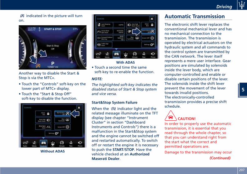
indicated in the picture will turnon.
Another way to disable the Start &Stop is via the MTC+.
• Touch the “Controls” soft-key on thelower part of MTC+ display.
• Touch the “Start & Stop Off”soft-key to disable the function.
• Touch a second time the samesoft-key to re-enable the function.
NOTE:
The highlighted soft-key indicates thedisabled status of Start & Stop systemand vice versa.
Start&Stop System Failure
When the indicator light and therelated message illuminate on the TFTdisplay (see chapter “InstrumentCluster” in section “DashboardInstruments and Controls”) there is amalfunction in the Start&Stop systemand the engine cannot be switched offand restarted automatically. To switchoff or restart the engine it is necessaryto push the START/STOP. Have thevehicle checked at an AuthorizedMaserati Dealer.
Automatic TransmissionThe electronic shift lever replaces theconventional mechanical lever and hasno mechanical connection to thetransmission. The transmission isoperated by electrical actuators on thehydraulic system and all commands tothe control system are transmitted bythe CAN network. The lever itselfrepresents a mere user interface. Gearpositions are simulated by solenoidsinside the lever body, which arecomputer-controlled and enable ordisable certain positions of the lever.The solenoids inside the shift leverprevent the movement of the levertowards invalid positions.The electronically-controlledtransmission provides a precise shiftschedule.
CAUTION!In order to properly use the automatictransmission, it is essential that youread through the whole chapter, sothat you can understand right fromthe start what the correct andpermitted operations are.
Damage to the transmission may occur
(Continued)
Without ADAS
With ADAS
Driving
5
207
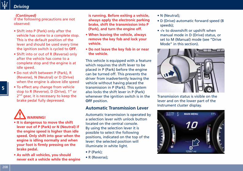
(Continued)if the following precautions are notobserved:
• Shift into P (Park) only after thevehicle has come to a complete stop.This is the default position of thelever and should be used every timethe ignition switch is cycled to OFF.
• Shift into or out of R (Reverse) onlyafter the vehicle has come to acomplete stop and the engine is atidle speed.
• Do not shift between P (Park), R(Reverse), N (Neutral) or D (Drive)when the engine is above idle speed
• To effect any change from vehiclestop to R (Reverse), D (Drive), 1st or2nd gear, it is necessary to keep thebrake pedal fully depressed.
WARNING!• It is dangerous to move the shiftlever out of P (Park) or N (Neutral) ifthe engine speed is higher than idlespeed. Only shift into gear when theengine is idling normally and whenyour foot is firmly pressing on thebrake pedal.
• As with all vehicles, you shouldnever exit a vehicle while the engine
is running. Before exiting a vehicle,always apply the electronic parkingbrake, shift the transmission into P(Park), and turn the engine off.
•When leaving the vehicle, alwaysremove the key fob and lock yourvehicle.
• Do not leave the key fob in or nearthe vehicle.
This vehicle is equipped with a featurewhich requires the shift lever to beplaced in P (Park) before the enginecan be turned off. This prevents thedriver from inadvertently leaving thevehicle without having placed thetransmission in P (Park). This systemalso locks the shift lever in P (Park)whenever the ignition switch is in theOFF position.
Automatic Transmission LeverAutomatic transmission is operated bya selection lever with unlock buttonlocated on the central console.By using the selection lever it ispossible to select the followingpositions, indicated on the top of thelever: the selected position willilluminate in white light.
• P (Park);• R (Reverse);
• N (Neutral);• D (Drive) automatic forward speed (8speeds);
• -/+ to downshift or upshift whenmanual mode in D (Drive) status, orset to M (Manual) mode (see “DriveMode” in this section).
Transmission status is visible on thelever and on the lower part of theInstrument cluster display.
Driving
5
208
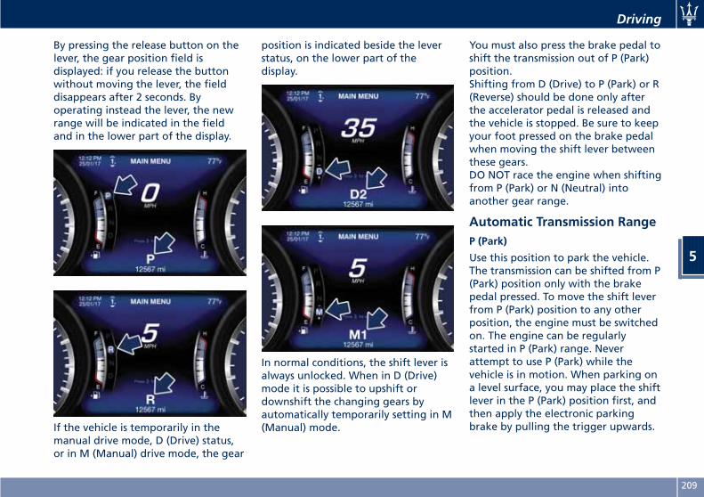
By pressing the release button on thelever, the gear position field isdisplayed: if you release the buttonwithout moving the lever, the fielddisappears after 2 seconds. Byoperating instead the lever, the newrange will be indicated in the fieldand in the lower part of the display.
If the vehicle is temporarily in themanual drive mode, D (Drive) status,or in M (Manual) drive mode, the gear
position is indicated beside the leverstatus, on the lower part of thedisplay.
In normal conditions, the shift lever isalways unlocked. When in D (Drive)mode it is possible to upshift ordownshift the changing gears byautomatically temporarily setting in M(Manual) mode.
You must also press the brake pedal toshift the transmission out of P (Park)position.Shifting from D (Drive) to P (Park) or R(Reverse) should be done only afterthe accelerator pedal is released andthe vehicle is stopped. Be sure to keepyour foot pressed on the brake pedalwhen moving the shift lever betweenthese gears.DO NOT race the engine when shiftingfrom P (Park) or N (Neutral) intoanother gear range.
Automatic Transmission RangeP (Park)
Use this position to park the vehicle.The transmission can be shifted from P(Park) position only with the brakepedal pressed. To move the shift leverfrom P (Park) position to any otherposition, the engine must be switchedon. The engine can be regularlystarted in P (Park) range. Neverattempt to use P (Park) while thevehicle is in motion. When parking ona level surface, you may place the shiftlever in the P (Park) position first, andthen apply the electronic parkingbrake by pulling the trigger upwards.
Driving
5
209

The Instrument cluster will display therelated indicator light and themessage for 5 seconds.
When parking on a hill, apply theparking brake before placing the shiftlever in P (Park).For enhanced security, turn the frontwheels toward the kerb on a downhilland away from the kerb on an uphillgrade.
WARNING!• Never use the P (Park) position as asubstitute for the electronic parkingbrake. Always apply the parkingbrake fully when parked to preventvehicle movement and possibleinjury or damage.
•Make sure the transmission is in P(Park) before leaving the vehicle.
CAUTION!• DO NOT race the engine whenshifting from P (Park) or N (Neutral)into another gear range, as this candamage the drivetrain.
• The following indicators should beused to ensure that you haveengaged the shift lever into the P(Park) position:
– when shifting into P (Park), pressthe unlock button on the shiftlever and push the lever all theway forward until it stops.
– with the brake pedal released,verify that P (Park) position isilluminated on the shift lever.
R (Reverse)
This range is used to move the vehiclebackward.We recommend to shift into R(Reverse) only after the vehicle hascome to a complete stop.
• Vehicle halted: switching between P(Park), R (Reverse) and D (Drive)requires pressing the unlock buttonon the lever and brake pedal: N(Neutral) is reached only by pressingthe unlock button on the lever.
• Vehicle moving: the driver can switchfrom R (Reverse) to N (Neutral), orvice versa, by pressing the unlockbutton on the shift lever.
N (Neutral)
• Vehicle halted and engine started:switching from N (Neutral) to R(Reverse), P (Park) and/or D (Drive)requires brake pedal and unlockbutton pressed.
• Vehicle moving: switching from N(Neutral) to R (Reverse) and/or D(Drive) requires pressing the unlockbutton. Switching to R (Reverse)starting from N (Neutral) is onlypossible if the vehicle is movingbackwards, while switching to D(Drive) starting from N (Neutral) is
Driving
5
210
only possible if the vehicle is movingforwards.
Set the parking brake and shift thetransmission into P (Park) if you mustleave the vehicle.
WARNING!Do not switch to N (Neutral) and/ornever turn off the ignition to coastdownhill. These are unsafe practicesthat limit driver’s response tochanging traffic or road conditions.
CAUTION!Towing the vehicle, coasting, ordriving for any other reason with thetransmission in N (Neutral) can resultin transmission damage. Refer to“Towing a Disabled Vehicle” in section6 for further information.
D (Drive)
This range should be used for mostcity and highway driving. It providesthe smoothest upshifts and downshiftsand the best fuel economy. Thetransmission automatically shifts upand down through all gears. The D(Drive) position provides optimum
driving characteristics under all normaloperating conditions of the vehicle.
• Vehicle stationary: switching from D(Drive) to R (Reverse) and/or to P(Park) requires brake pedal andunlock button pressed: reaching N(Neutral) starting from D (Drive) isallowed by only pressing the unlockbutton on the shift lever.
• To enable special operations whilethe car is moving at a low speed,such as getting out of marsh orsnow, it is possible to run quicklyfrom D (Drive) to R (Reverse), andvice versa, by pressing the resetbutton on the gear shift lever.
• Vehicle moving: switching to N(Neutral) from D (Drive) requires theunlock button on the shift leverpressed.
• From D (Drive) selected mode it isalways possible to switch to M(Manual), by pressing the M(Manual) button: the Led indicatorbeside the button will light up; toreturn to D (Drive) position, thesame action should be performed asthe LED will turn off.
• When in D (Drive) mode, moving theshift lever forward or backwards tothe next step without pressing theunlock button on the lever will cause
the system to enter a temporaryfunction and enable the manualshift mode. This range is indicatedwith the symbols “-/+” on the leftand right sides of the “D” letter onthe gear range field of the display.The system will then switch back toautomatic mode according to timeelapsed in “temporary” mode anddriving conditions.
At extremely cold temperatures(-23°F/-30°C or below), transmissionmay be affected by the lowtemperature of the engine andtransmission. Normal operation willresume once the transmissiontemperature has risen to a normallevel.
Transmission Malfunction andOverheating ConditionsTransmission Emergency ControlTransmission function is electronicallymonitored to detect abnormalconditions. If a condition that couldresult in transmission damage isdetected, Transmission Limp HomeMode will be activated. In thissituation, the transmission mayoperate only in certain gears, or maynot shift at all. In some situations, thetransmission system may not
Driving
5
211
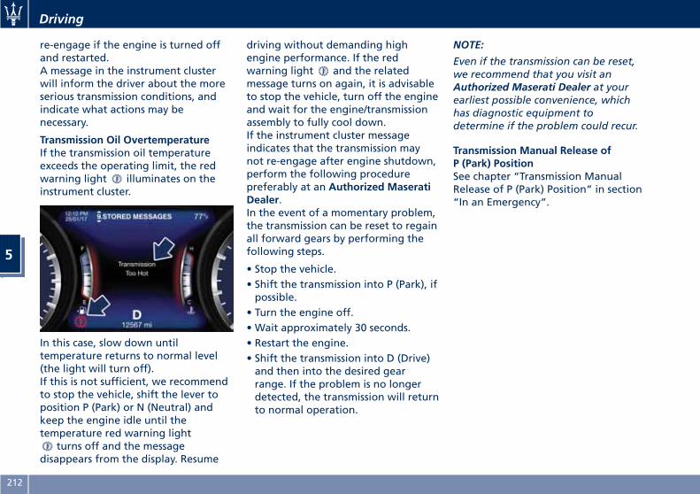
re-engage if the engine is turned offand restarted.A message in the instrument clusterwill inform the driver about the moreserious transmission conditions, andindicate what actions may benecessary.
Transmission Oil OvertemperatureIf the transmission oil temperatureexceeds the operating limit, the redwarning light illuminates on theinstrument cluster.
In this case, slow down untiltemperature returns to normal level(the light will turn off).If this is not sufficient, we recommendto stop the vehicle, shift the lever toposition P (Park) or N (Neutral) andkeep the engine idle until thetemperature red warning light
turns off and the messagedisappears from the display. Resume
driving without demanding highengine performance. If the redwarning light and the relatedmessage turns on again, it is advisableto stop the vehicle, turn off the engineand wait for the engine/transmissionassembly to fully cool down.If the instrument cluster messageindicates that the transmission maynot re-engage after engine shutdown,perform the following procedurepreferably at an Authorized MaseratiDealer.In the event of a momentary problem,the transmission can be reset to regainall forward gears by performing thefollowing steps.
• Stop the vehicle.• Shift the transmission into P (Park), ifpossible.
• Turn the engine off.• Wait approximately 30 seconds.• Restart the engine.• Shift the transmission into D (Drive)and then into the desired gearrange. If the problem is no longerdetected, the transmission will returnto normal operation.
NOTE:
Even if the transmission can be reset,we recommend that you visit anAuthorized Maserati Dealer at yourearliest possible convenience, whichhas diagnostic equipment todetermine if the problem could recur.
Transmission Manual Release ofP (Park) PositionSee chapter “Transmission ManualRelease of P (Park) Position” in section“In an Emergency”.
Driving
5
212
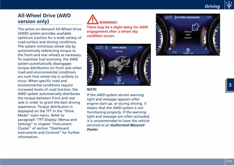
All-Wheel Drive (AWDversion only)The active on-demand All-Wheel Drive(AWD) system provides availableoptimum traction for a wide variety ofroad surface and driving conditions.The system minimizes wheel slip byautomatically redirecting torque tothe front and rear wheels as necessary.To maximise fuel economy, the AWDsystem automatically disangagestorque distribution on front axle whenroad and environmental conditionsare such that wheel slip is unlikely tooccur. When specific road andenvironmental conditions requireincreased levels of road traction, theAWD system automatically distributesthe torque between front and rearaxle in order to grant the best drivingexperience. Torque distribution isdisplayed on the TFT in the “DriveMode” main menu. Refer toparagraph “TFT Display: Menus andSettings” in chapter “InstrumentCluster” of section “DashboardInstruments and Controls” for furtherinformation.
WARNING!There may be a slight delay for AWDengagement after a wheel slipcondition occurs.
NOTE:
If the AWD system service warninglight and message appears afterengine start up, or during driving, itmeans that the AWD system is notfunctioning properly. If the warninglight and message are often activated,it is recommended to have the vehicleserviced at an Authorized MaseratiDealer.
.
Driving
5
213
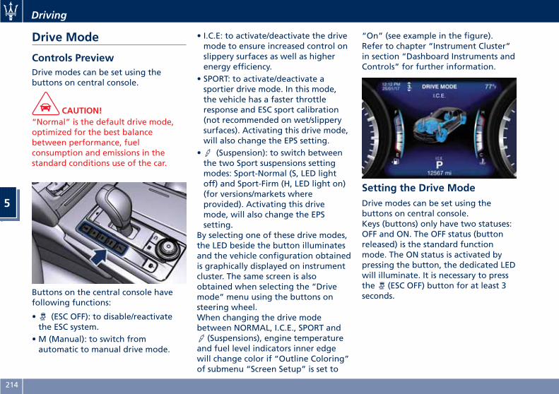
Drive Mode
Controls PreviewDrive modes can be set using thebuttons on central console.
CAUTION!“Normal” is the default drive mode,optimized for the best balancebetween performance, fuelconsumption and emissions in thestandard conditions use of the car.
Buttons on the central console havefollowing functions:
• (ESC OFF): to disable/reactivatethe ESC system.
• M (Manual): to switch fromautomatic to manual drive mode.
• I.C.E: to activate/deactivate the drivemode to ensure increased control onslippery surfaces as well as higherenergy efficiency.
• SPORT: to activate/deactivate asportier drive mode. In this mode,the vehicle has a faster throttleresponse and ESC sport calibration(not recommended on wet/slipperysurfaces). Activating this drive mode,will also change the EPS setting.
• (Suspension): to switch betweenthe two Sport suspensions settingmodes: Sport-Normal (S, LED lightoff) and Sport-Firm (H, LED light on)(for versions/markets whereprovided). Activating this drivemode, will also change the EPSsetting.
By selecting one of these drive modes,the LED beside the button illuminatesand the vehicle configuration obtainedis graphically displayed on instrumentcluster. The same screen is alsoobtained when selecting the “Drivemode” menu using the buttons onsteering wheel.When changing the drive modebetween NORMAL, I.C.E., SPORT and
(Suspensions), engine temperatureand fuel level indicators inner edgewill change color if “Outline Coloring”of submenu “Screen Setup” is set to
“On” (see example in the figure).Refer to chapter “Instrument Cluster”in section “Dashboard Instruments andControls” for further information.
Setting the Drive ModeDrive modes can be set using thebuttons on central console.Keys (buttons) only have two statuses:OFF and ON. The OFF status (buttonreleased) is the standard functionmode. The ON status is activated bypressing the button, the dedicated LEDwill illuminate. It is necessary to pressthe (ESC OFF) button for at least 3seconds.
Driving
5
214
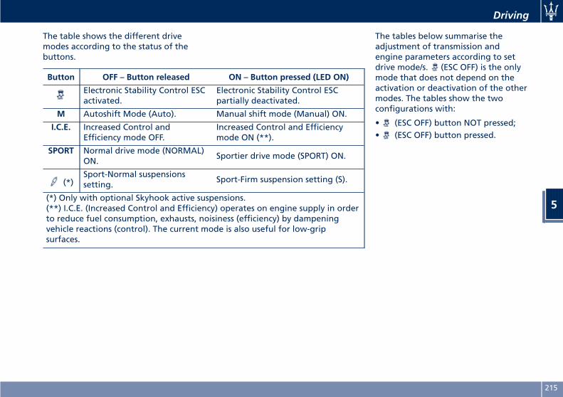
The table shows the different drivemodes according to the status of thebuttons.
The tables below summarise theadjustment of transmission andengine parameters according to setdrive mode/s. (ESC OFF) is the onlymode that does not depend on theactivation or deactivation of the othermodes. The tables show the twoconfigurations with:
• (ESC OFF) button NOT pressed;• (ESC OFF) button pressed.
Button OFF – Button released ON – Button pressed (LED ON)
Electronic Stability Control ESCactivated.
Electronic Stability Control ESCpartially deactivated.
M Autoshift Mode (Auto). Manual shift mode (Manual) ON.
I.C.E. Increased Control andEfficiency mode OFF.
Increased Control and Efficiencymode ON (**).
SPORT Normal drive mode (NORMAL)ON.
Sportier drive mode (SPORT) ON.
(*)Sport-Normal suspensionssetting.
Sport-Firm suspension setting (S).
(*) Only with optional Skyhook active suspensions.(**) I.C.E. (Increased Control and Efficiency) operates on engine supply in orderto reduce fuel consumption, exhausts, noisiness (efficiency) by dampeningvehicle reactions (control). The current mode is also useful for low-gripsurfaces.
Driving
5
215
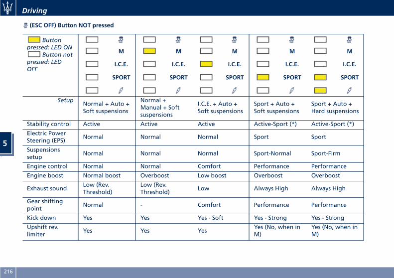
(ESC OFF) Button NOT pressed
Buttonpressed: LED ON
Button notpressed: LEDOFF
M M M M M
I.C.E. I.C.E. I.C.E. I.C.E. I.C.E.
SPORT SPORT SPORT SPORT SPORT
SetupNormal + Auto +Soft suspensions
Normal +Manual + Softsuspensions
I.C.E. + Auto +Soft suspensions
Sport + Auto +Soft suspensions
Sport + Auto +Hard suspensions
Stability control Active Active Active Active-Sport (*) Active-Sport (*)
Electric PowerSteering (EPS)
Normal Normal Normal Sport Sport
Suspensionssetup
Normal Normal Normal Sport-Normal Sport-Firm
Engine control Normal Normal Comfort Performance Performance
Engine boost Normal boost Overboost Low boost Overboost Overboost
Exhaust soundLow (Rev.Threshold)
Low (Rev.Threshold)
Low Always High Always High
Gear shiftingpoint
Normal - Comfort Performance Performance
Kick down Yes Yes Yes - Soft Yes - Strong Yes - Strong
Upshift rev.limiter
Yes Yes YesYes (No, when inM)
Yes (No, when inM)
Driving
5
216
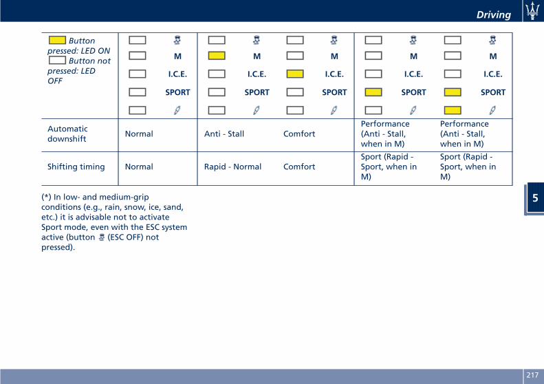
Buttonpressed: LED ON
Button notpressed: LEDOFF
M M M M M
I.C.E. I.C.E. I.C.E. I.C.E. I.C.E.
SPORT SPORT SPORT SPORT SPORT
Automaticdownshift
Normal Anti - Stall ComfortPerformance(Anti - Stall,when in M)
Performance(Anti - Stall,when in M)
Shifting timing Normal Rapid - Normal ComfortSport (Rapid -Sport, when inM)
Sport (Rapid -Sport, when inM)
(*) In low- and medium-gripconditions (e.g., rain, snow, ice, sand,etc.) it is advisable not to activateSport mode, even with the ESC systemactive (button (ESC OFF) notpressed).
Driving
5
217
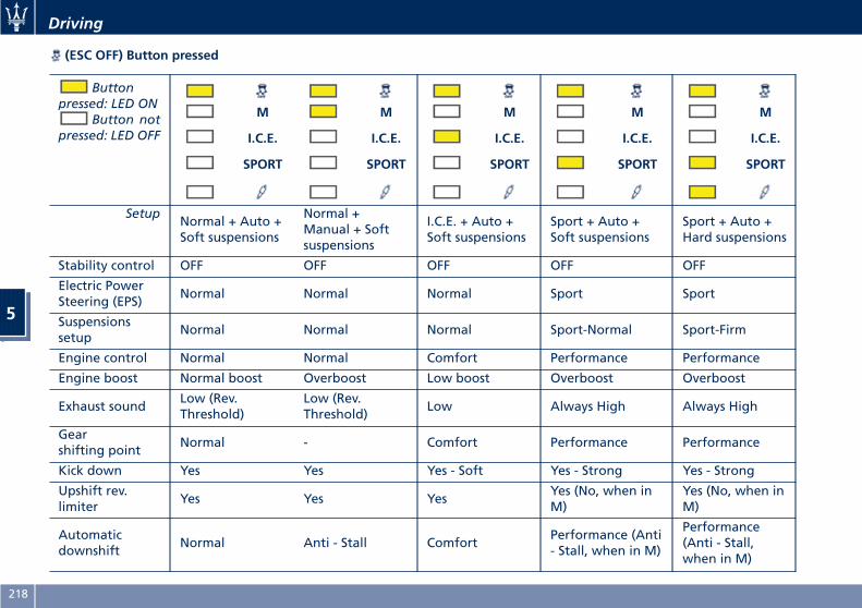
(ESC OFF) Button pressed
Buttonpressed: LED ON
Button notpressed: LED OFF
M M M M M
I.C.E. I.C.E. I.C.E. I.C.E. I.C.E.
SPORT SPORT SPORT SPORT SPORT
SetupNormal + Auto +Soft suspensions
Normal +Manual + Softsuspensions
I.C.E. + Auto +Soft suspensions
Sport + Auto +Soft suspensions
Sport + Auto +Hard suspensions
Stability control OFF OFF OFF OFF OFF
Electric PowerSteering (EPS)
Normal Normal Normal Sport Sport
Suspensionssetup
Normal Normal Normal Sport-Normal Sport-Firm
Engine control Normal Normal Comfort Performance Performance
Engine boost Normal boost Overboost Low boost Overboost Overboost
Exhaust soundLow (Rev.Threshold)
Low (Rev.Threshold)
Low Always High Always High
Gearshifting point
Normal - Comfort Performance Performance
Kick down Yes Yes Yes - Soft Yes - Strong Yes - Strong
Upshift rev.limiter
Yes Yes YesYes (No, when inM)
Yes (No, when inM)
Automaticdownshift
Normal Anti - Stall ComfortPerformance (Anti- Stall, when in M)
Performance(Anti - Stall,when in M)
Driving
5
218
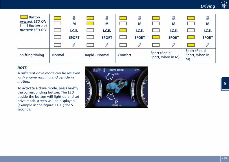
Buttonpressed: LED ON
Button notpressed: LED OFF
M M M M M
I.C.E. I.C.E. I.C.E. I.C.E. I.C.E.
SPORT SPORT SPORT SPORT SPORT
Shifting timing Normal Rapid - Normal ComfortSport (Rapid -Sport, when in M)
Sport (Rapid -Sport, when inM)
NOTE:
A different drive mode can be set evenwith engine running and vehicle inmotion.
To activate a drive mode, press brieflythe corresponding button. The LEDbeside the button will light up and setdrive mode screen will be displayed(example in the figure: I.C.E.) for 5seconds.
Driving
5
219
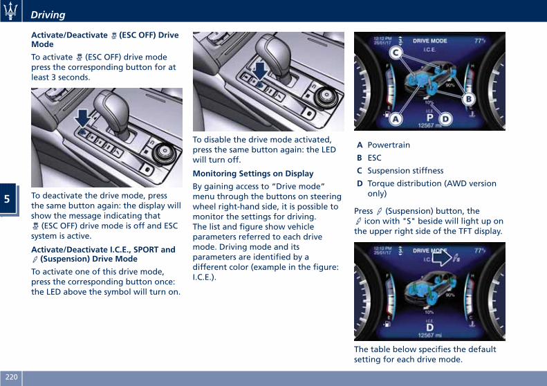
Activate/Deactivate (ESC OFF) DriveMode
To activate (ESC OFF) drive modepress the corresponding button for atleast 3 seconds.
To deactivate the drive mode, pressthe same button again: the display willshow the message indicating that
(ESC OFF) drive mode is off and ESCsystem is active.
Activate/Deactivate I.C.E., SPORT and(Suspension) Drive Mode
To activate one of this drive mode,press the corresponding button once:the LED above the symbol will turn on.
To disable the drive mode activated,press the same button again: the LEDwill turn off.
Monitoring Settings on Display
By gaining access to “Drive mode”menu through the buttons on steeringwheel right-hand side, it is possible tomonitor the settings for driving.The list and figure show vehicleparameters referred to each drivemode. Driving mode and itsparameters are identified by adifferent color (example in the figure:I.C.E.).
A Powertrain
B ESC
C Suspension stiffness
D Torque distribution (AWD versiononly)
Press (Suspension) button, theicon with "S" beside will light up on
the upper right side of the TFT display.
The table below specifies the defaultsetting for each drive mode.
Driving
5
220
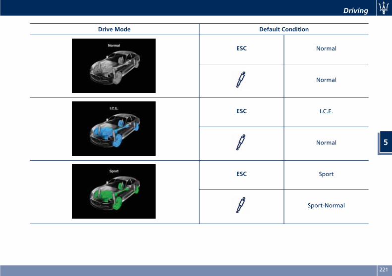
Drive Mode Default Condition
ESC Normal
Normal
ESC I.C.E.
Normal
ESC Sport
Sport-Normal
Driving
5
221
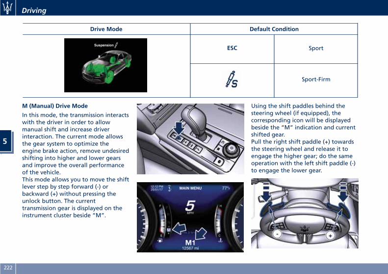
Drive Mode Default Condition
ESC Sport
Sport-Firm
M (Manual) Drive Mode
In this mode, the transmission interactswith the driver in order to allowmanual shift and increase driverinteraction. The current mode allowsthe gear system to optimize theengine brake action, remove undesiredshifting into higher and lower gearsand improve the overall performanceof the vehicle.This mode allows you to move the shiftlever step by step forward (-) orbackward (+) without pressing theunlock button. The currenttransmission gear is displayed on theinstrument cluster beside “M”.
Using the shift paddles behind thesteering wheel (if equipped), thecorresponding icon will be displayedbeside the “M” indication and currentshifted gear.Pull the right shift paddle (+) towardsthe steering wheel and release it toengage the higher gear; do the sameoperation with the left shift paddle (-)to engage the lower gear.
Driving
5
222
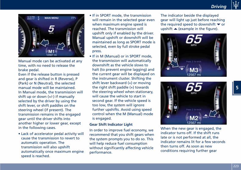
Manual mode can be activated at anytime, with no need to release thebrake pedal.Even if the release button is pressedand gear is shifted in R (Reverse), P(Park) or N (Neutral), the selectedmanual mode will be maintained.In Manual mode, the transmission willshift up or down (+/-) if manuallyselected by the driver by using theshift lever, or shift paddles on thesteering wheel (if present). Thetransmission remains in the engagedgear until the driver shifts intoanother higher or lower gear, exceptin the following cases.
• Lack of accelerator pedal activity willcause the transmission to revert toautomatic operation. Thetransmission will also upshiftautomatically once maximum enginespeed is reached.
• If in SPORT mode, the transmissionwill remain in the selected gear evenwhen maximum engine speed isreached. The transmission willupshift only if enabled by the driver.Manual upshift or downshift will bemaintained as long as SPORT mode isselected, even by full stroke pedalpress.
• If in M (Manual) or in SPORT mode,the transmission will automaticallydownshift as the vehicle slows tohalt (to prevent engine lagging) andthe current gear will be displayed onthe instrument cluster. Shifting theshift lever backward (+) or movingthe right shift paddle (+) towardsthe steering wheel when stationary,will cause the vehicle to start insecond gear. If the vehicle speed istoo low, the system will ignorefurther upshifts. Avoid using speedcontrol when the M (Manual) modeis engaged.
Gear Shift Indicator Light
In order to improve fuel economy, werecommend that you shift gears whenthe system prompts you to do so. Thiswill help reduce fuel consumptionwithout significantly affecting vehicleperformance.
The indicator beside the displayedgear will light up just before reachingthe required speed to downshift orupshift (example in the figure).
When the new gear is engaged, theindicator turns off. If the shift runslate or is not performed at all, theindicator remains lit for a few secondsthen turns off. As soon as newconditions requiring further gear
Driving
5
223
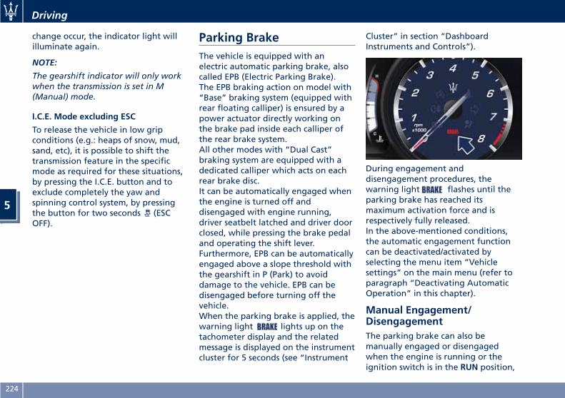
change occur, the indicator light willilluminate again.
NOTE:
The gearshift indicator will only workwhen the transmission is set in M(Manual) mode.
I.C.E. Mode excluding ESC
To release the vehicle in low gripconditions (e.g.: heaps of snow, mud,sand, etc), it is possible to shift thetransmission feature in the specificmode as required for these situations,by pressing the I.C.E. button and toexclude completely the yaw andspinning control system, by pressingthe button for two seconds (ESCOFF).
Parking BrakeThe vehicle is equipped with anelectric automatic parking brake, alsocalled EPB (Electric Parking Brake).The EPB braking action on model with“Base” braking system (equipped withrear floating calliper) is ensured by apower actuator directly working onthe brake pad inside each calliper ofthe rear brake system.All other modes with “Dual Cast”braking system are equipped with adedicated calliper which acts on eachrear brake disc.It can be automatically engaged whenthe engine is turned off anddisengaged with engine running,driver seatbelt latched and driver doorclosed, while pressing the brake pedaland operating the shift lever.Furthermore, EPB can be automaticallyengaged above a slope threshold withthe gearshift in P (Park) to avoiddamage to the vehicle. EPB can bedisengaged before turning off thevehicle.When the parking brake is applied, thewarning light lights up on thetachometer display and the relatedmessage is displayed on the instrumentcluster for 5 seconds (see “Instrument
Cluster” in section “DashboardInstruments and Controls”).
During engagement anddisengagement procedures, thewarning light flashes until theparking brake has reached itsmaximum activation force and isrespectively fully released.In the above-mentioned conditions,the automatic engagement functioncan be deactivated/activated byselecting the menu item “Vehiclesettings” on the main menu (refer toparagraph “Deactivating AutomaticOperation” in this chapter).
Manual Engagement/DisengagementThe parking brake can also bemanually engaged or disengagedwhen the engine is running or theignition switch is in the RUN position,
Driving
5
224
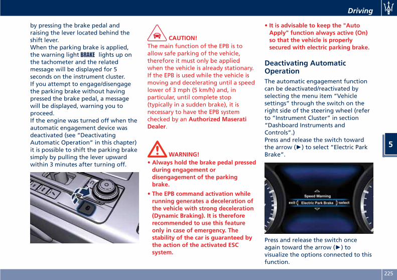
by pressing the brake pedal andraising the lever located behind theshift lever.When the parking brake is applied,the warning light lights up onthe tachometer and the relatedmessage will be displayed for 5seconds on the instrument cluster.If you attempt to engage/disengagethe parking brake without havingpressed the brake pedal, a messagewill be displayed, warning you toproceed.If the engine was turned off when theautomatic engagement device wasdeactivated (see “DeactivatingAutomatic Operation” in this chapter)it is possible to shift the parking brakesimply by pulling the lever upwardwithin 3 minutes after turning off.
CAUTION!The main function of the EPB is toallow safe parking of the vehicle,therefore it must only be appliedwhen the vehicle is already stationary.If the EPB is used while the vehicle ismoving and decelerating until a speedlower of 3 mph (5 km/h) and, inparticular, until complete stop(typically in a sudden brake), it isnecessary to have the EPB systemchecked by an Authorized MaseratiDealer.
WARNING!• Always hold the brake pedal pressedduring engagement ordisengagement of the parkingbrake.
• The EPB command activation whilerunning generates a deceleration ofthe vehicle with strong deceleration(Dynamic Braking). It is thereforerecommended to use this featureonly in case of emergency. Thestability of the car is guaranteed bythe action of the activated ESCsystem.
• It is advisable to keep the "AutoApply" function always active (On)so that the vehicle is properlysecured with electric parking brake.
Deactivating AutomaticOperationThe automatic engagement functioncan be deactivated/reactivated byselecting the menu item “Vehiclesettings” through the switch on theright side of the steering wheel (referto “Instrument Cluster” in section“Dashboard Instruments andControls”.)Press and release the switch towardthe arrow (►) to select “Electric ParkBrake”.
Press and release the switch onceagain toward the arrow (►) tovisualize the options connected to thisfunction.
Driving
5
225
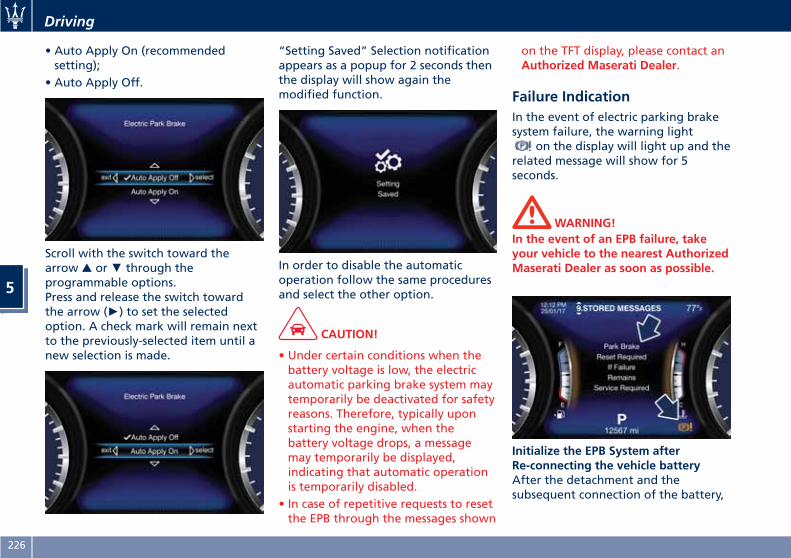
• Auto Apply On (recommendedsetting);
• Auto Apply Off.
Scroll with the switch toward thearrow ▲ or▼ through theprogrammable options.Press and release the switch towardthe arrow (►) to set the selectedoption. A check mark will remain nextto the previously-selected item until anew selection is made.
“Setting Saved” Selection notificationappears as a popup for 2 seconds thenthe display will show again themodified function.
In order to disable the automaticoperation follow the same proceduresand select the other option.
CAUTION!
• Under certain conditions when thebattery voltage is low, the electricautomatic parking brake system maytemporarily be deactivated for safetyreasons. Therefore, typically uponstarting the engine, when thebattery voltage drops, a messagemay temporarily be displayed,indicating that automatic operationis temporarily disabled.
• In case of repetitive requests to resetthe EPB through the messages shown
on the TFT display, please contact anAuthorized Maserati Dealer.
Failure IndicationIn the event of electric parking brakesystem failure, the warning light
on the display will light up and therelated message will show for 5seconds.
WARNING!In the event of an EPB failure, takeyour vehicle to the nearest AuthorizedMaserati Dealer as soon as possible.
Initialize the EPB System afterRe-connecting the vehicle batteryAfter the detachment and thesubsequent connection of the battery,
Driving
5
226
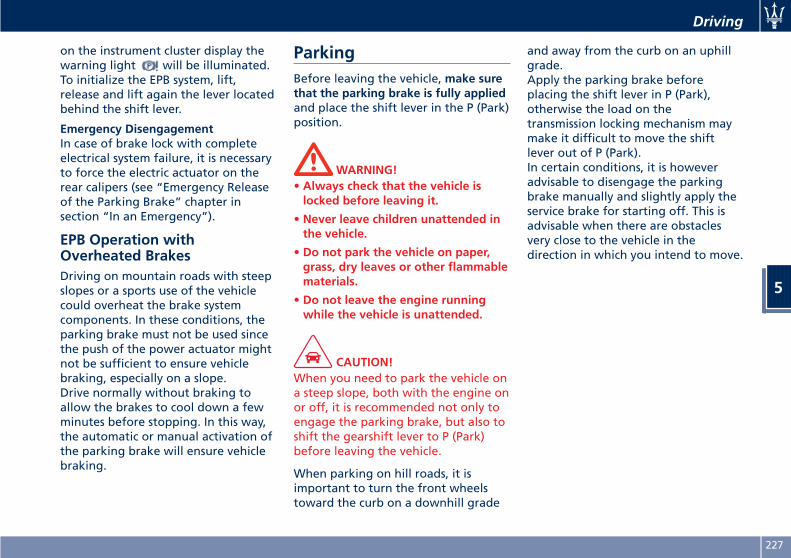
on the instrument cluster display thewarning light will be illuminated.To initialize the EPB system, lift,release and lift again the lever locatedbehind the shift lever.
Emergency DisengagementIn case of brake lock with completeelectrical system failure, it is necessaryto force the electric actuator on therear calipers (see “Emergency Releaseof the Parking Brake” chapter insection “In an Emergency”).
EPB Operation withOverheated BrakesDriving on mountain roads with steepslopes or a sports use of the vehiclecould overheat the brake systemcomponents. In these conditions, theparking brake must not be used sincethe push of the power actuator mightnot be sufficient to ensure vehiclebraking, especially on a slope.Drive normally without braking toallow the brakes to cool down a fewminutes before stopping. In this way,the automatic or manual activation ofthe parking brake will ensure vehiclebraking.
ParkingBefore leaving the vehicle, make surethat the parking brake is fully appliedand place the shift lever in the P (Park)position.
WARNING!• Always check that the vehicle islocked before leaving it.
• Never leave children unattended inthe vehicle.
• Do not park the vehicle on paper,grass, dry leaves or other flammablematerials.
• Do not leave the engine runningwhile the vehicle is unattended.
CAUTION!When you need to park the vehicle ona steep slope, both with the engine onor off, it is recommended not only toengage the parking brake, but also toshift the gearshift lever to P (Park)before leaving the vehicle.
When parking on hill roads, it isimportant to turn the front wheelstoward the curb on a downhill grade
and away from the curb on an uphillgrade.Apply the parking brake beforeplacing the shift lever in P (Park),otherwise the load on thetransmission locking mechanism maymake it difficult to move the shiftlever out of P (Park).In certain conditions, it is howeveradvisable to disengage the parkingbrake manually and slightly apply theservice brake for starting off. This isadvisable when there are obstaclesvery close to the vehicle in thedirection in which you intend to move.
Driving
5
227
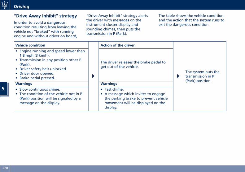
“Drive Away Inhibit” strategyIn order to avoid a dangerouscondition resulting from leaving thevehicle not “braked” with runningengine and without driver on board,
“Drive Away Inhibit” strategy alertsthe driver with messages on theinstrument cluster display andsounding chimes, then puts thetransmission in P (Park).
The table shows the vehicle conditionand the action that the system runs toexit the dangerous condition.
Vehicle condition Action of the driver
The system puts thetransmission in P(Park) position.
• Engine running and speed lower than1.8 mph (3 km/h).
• Transmission in any position other P(Park).
• Driver safety belt unlocked.• Driver door opened.• Brake pedal pressed.
The driver releases the brake pedal toget out of the vehicle.
Warnings Warnings
• Slow continuous chime.• The condition of the vehicle not in P(Park) position will be signaled by amessage on the display.
• Fast chime.• A message which invites to engagethe parking brake to prevent vehiclemovement will be displayed on thedisplay.
Driving
5
228
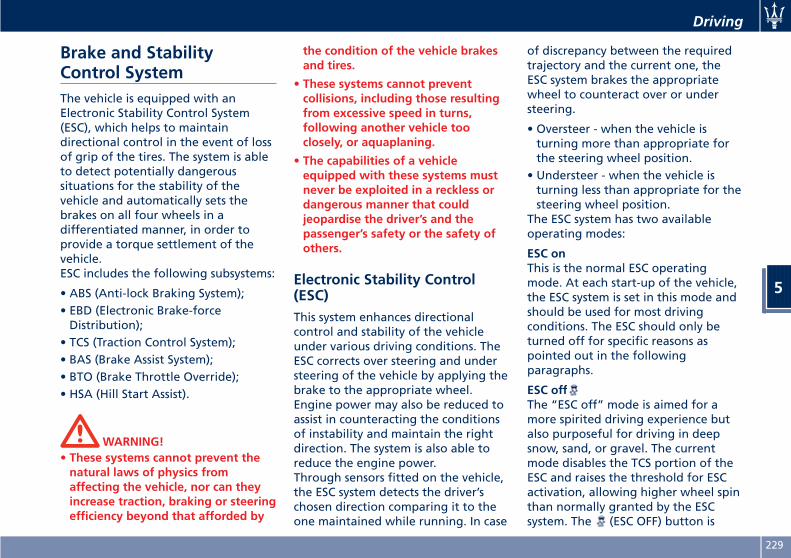
Brake and StabilityControl SystemThe vehicle is equipped with anElectronic Stability Control System(ESC), which helps to maintaindirectional control in the event of lossof grip of the tires. The system is ableto detect potentially dangeroussituations for the stability of thevehicle and automatically sets thebrakes on all four wheels in adifferentiated manner, in order toprovide a torque settlement of thevehicle.ESC includes the following subsystems:
• ABS (Anti-lock Braking System);• EBD (Electronic Brake-forceDistribution);
• TCS (Traction Control System);• BAS (Brake Assist System);• BTO (Brake Throttle Override);• HSA (Hill Start Assist).
WARNING!• These systems cannot prevent thenatural laws of physics fromaffecting the vehicle, nor can theyincrease traction, braking or steeringefficiency beyond that afforded by
the condition of the vehicle brakesand tires.
• These systems cannot preventcollisions, including those resultingfrom excessive speed in turns,following another vehicle tooclosely, or aquaplaning.
• The capabilities of a vehicleequipped with these systems mustnever be exploited in a reckless ordangerous manner that couldjeopardise the driver’s and thepassenger’s safety or the safety ofothers.
Electronic Stability Control(ESC)This system enhances directionalcontrol and stability of the vehicleunder various driving conditions. TheESC corrects over steering and understeering of the vehicle by applying thebrake to the appropriate wheel.Engine power may also be reduced toassist in counteracting the conditionsof instability and maintain the rightdirection. The system is also able toreduce the engine power.Through sensors fitted on the vehicle,the ESC system detects the driver’schosen direction comparing it to theone maintained while running. In case
of discrepancy between the requiredtrajectory and the current one, theESC system brakes the appropriatewheel to counteract over or understeering.
• Oversteer - when the vehicle isturning more than appropriate forthe steering wheel position.
• Understeer - when the vehicle isturning less than appropriate for thesteering wheel position.
The ESC system has two availableoperating modes:
ESC onThis is the normal ESC operatingmode. At each start-up of the vehicle,the ESC system is set in this mode andshould be used for most drivingconditions. The ESC should only beturned off for specific reasons aspointed out in the followingparagraphs.
ESC offThe “ESC off” mode is aimed for amore spirited driving experience butalso purposeful for driving in deepsnow, sand, or gravel. The currentmode disables the TCS portion of theESC and raises the threshold for ESCactivation, allowing higher wheel spinthan normally granted by the ESCsystem. The (ESC OFF) button is
Driving
5
229
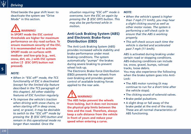
fitted beside the gear shift lever: todeactivate the system see “DriveMode” in this section.
WARNING!In SPORT mode the ESC controlthresholds are higher for maximumperformance on dry road surface. Toensure maximum security of the ESC,it is recommended not to activateSPORT mode on surfaces withmedium- and low-grip (e.g., wet,snow, dirt, etc..) with ESC systemactive ( (ESC OFF) button notpressed).
NOTE:
•When in “ESC off” mode, the TCSfunctionality of ESC is deactivated(except for the limited slip featuredescribed in the TCS paragraph ofthis chapter). All other stabilityfeatures of ESC function regularly.
• To improve the vehicle's tractionwhen driving with snow chains, orwhen starting off in deep snow,sand, or gravel, it may be desirableto switch to the “ESC off” mode bypressing the (ESC OFF) button andremain in this operational mode nolonger than needed. Once the
situation requiring “ESC off” mode isovercome, turn the ESC on again bypressing the (ESC OFF) button. Thismay also be performed while inmotion.
Anti-Lock Braking System (ABS)and Electronic Brake-forceDistribution (EBD)The Anti-Lock Braking System (ABS)provides increased vehicle stability andbrake performance under mostbraking conditions. The systemautomatically “pumps” the brakesduring severe braking to preventwheel lock-up.The Electronic Brake-force Distribution(EBD) prevents the rear wheels fromover-braking and provides greatercontrol of available braking forcesapplied to the rear axle.
WARNING!The ABS helps prevent the wheelsfrom locking, but it does not increasethe physical grip limits between thetires and the road. Therefore, alwayskeep a safe distance from the vehiclein front of yours and reduce yourspeed when entering a curve.
NOTE:
•When the vehicle's speed is higherthan 7 mph (11 km/h), you may heara slight clicking sound as well asother motor noises. The system isperforming a self-check cycle toensure that the ABS is workingproperly.
• This self-check occurs each time thevehicle is started and acceleratedpast 7 mph (11 km/h).
ABS is activated during braking undercertain road or stopping conditions.ABS-inducing conditions can includeice, snow, gravel, bumps, railroadtracks, loose debris.You may also experience the followingwhen the brake system goes into Anti-Lock:
• The ABS motor running (it maycontinue to run for a short time afterthe vehicle stops).
• The clicking sound of solenoid valves.• Brake pedal pulsations.• A slight drop or fall away of thebrake pedal at the end of the stop.These are all normal characteristics ofABS functioning.
Driving
5
230
WARNING!• The ABS contains sophisticatedelectronic equipment that may besusceptible to interference causedby improperly installed or highoutput radio transmittingequipment. This interference cancause possible loss of anti-lockbraking capability. Installation ofsuch equipment should beperformed by qualified Maseratipersonnel.
• Pumping the Anti-Lock Brakes willdiminish their effectiveness.Pumping brakes makes the stoppingdistance longer. Just press firmly onyour brake pedal when you need toslow down or stop. Do not pumpbrakes.
Traction Control System (TCS)The current device is an integral partof the ESC system. It operatesautomatically by reducing the powertransmitted by the engine in case ofslipping, loss of grip on wet floor(aquaplaning), acceleration onslippery snow-covered or frozensurfaces, etc.
Activating under slip conditionsdifferent control systems:
• if slippage affects both drive wheels,it reduces the power transmitted bythe engine;
• if slippage only affects one drivewheel, it brakes the slipping wheelautomatically.
Brake Assist System (BAS)This system completes the ABS systemby optimizing the vehicle brakingcapacity during emergency brakemaneuvers. The system detects anemergency braking situation bysensing the rate and amount of brakeapplication and then applies optimumpressure to the brakes in order to helpreduce braking distances.The quick brake coupling is optimalfor BAS performances. In order to fullyexploit the system, apply continuousbrake pedal pressure during the entirevehicle stop sequence. Do not reducebrake pedal pressure earlier thanrequired. Once the brake pedal isreleased, the BAS is deactivated.
Brake Throttle Override (BTO)To complete the range of systems thatassist braking, the vehicle is equippedwith BTO, which is designed to stop
the vehicle even when it is beingaccelerated. If the brake pedal isdepressed together with theaccelerator, the system does notconsider as “conflict” the sequence“brake-first-then-accelerator” of pedalapplication and it will not engage theBTO. When the system recognizes thesequence “accelerator-first-then-brake-pressed” as “conflict” theengine power should be automaticallyreduced and, if the driver continues todepress the accelerator, the system canmake the vehicle to come to acomplete stop.Additionally, if the brake pedal isreleased when the accelerator is stilldepressed, the corresponding enginetorque increase gradually to a safevalue.During this event, the ETC lightindicator will illuminate. The systemexits from this strategy when theaccelerator pedal is completelyunstuck.
Hill Start Assist (HSA)The HSA system is designed to assistthe driver when starting a vehicleuphill. HSA will maintain the level ofbrake pressure applied for a shortperiod of time also after releasing thebrake pedal.
Driving
5
231
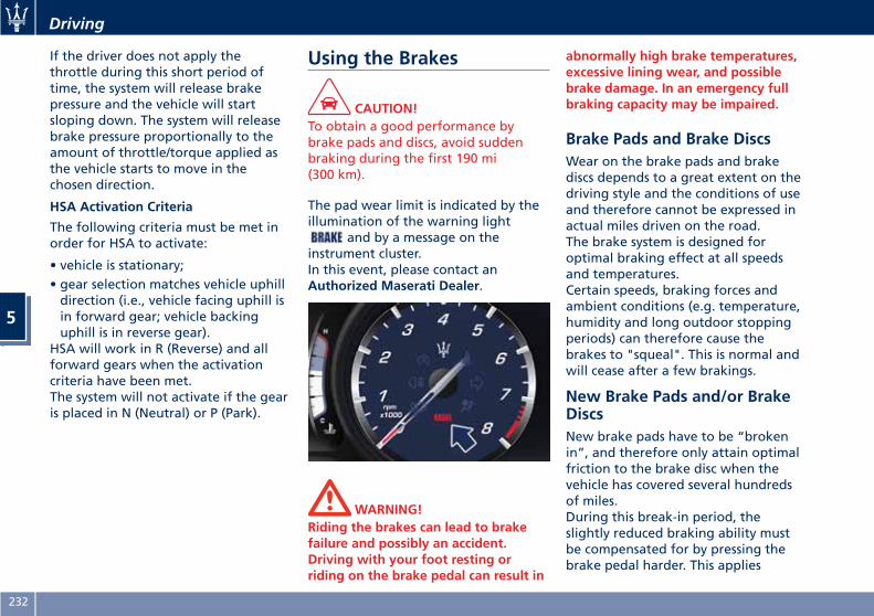
If the driver does not apply thethrottle during this short period oftime, the system will release brakepressure and the vehicle will startsloping down. The system will releasebrake pressure proportionally to theamount of throttle/torque applied asthe vehicle starts to move in thechosen direction.
HSA Activation Criteria
The following criteria must be met inorder for HSA to activate:
• vehicle is stationary;• gear selection matches vehicle uphilldirection (i.e., vehicle facing uphill isin forward gear; vehicle backinguphill is in reverse gear).
HSA will work in R (Reverse) and allforward gears when the activationcriteria have been met.The system will not activate if the gearis placed in N (Neutral) or P (Park).
Using the Brakes
CAUTION!To obtain a good performance bybrake pads and discs, avoid suddenbraking during the first 190 mi(300 km).
The pad wear limit is indicated by theillumination of the warning light
and by a message on theinstrument cluster.In this event, please contact anAuthorized Maserati Dealer.
WARNING!Riding the brakes can lead to brakefailure and possibly an accident.Driving with your foot resting orriding on the brake pedal can result in
abnormally high brake temperatures,excessive lining wear, and possiblebrake damage. In an emergency fullbraking capacity may be impaired.
Brake Pads and Brake DiscsWear on the brake pads and brakediscs depends to a great extent on thedriving style and the conditions of useand therefore cannot be expressed inactual miles driven on the road.The brake system is designed foroptimal braking effect at all speedsand temperatures.Certain speeds, braking forces andambient conditions (e.g. temperature,humidity and long outdoor stoppingperiods) can therefore cause thebrakes to "squeal". This is normal andwill cease after a few brakings.
New Brake Pads and/or BrakeDiscsNew brake pads have to be “brokenin”, and therefore only attain optimalfriction to the brake disc when thevehicle has covered several hundredsof miles.During this break-in period, theslightly reduced braking ability mustbe compensated for by pressing thebrake pedal harder. This applies
Driving
5
232
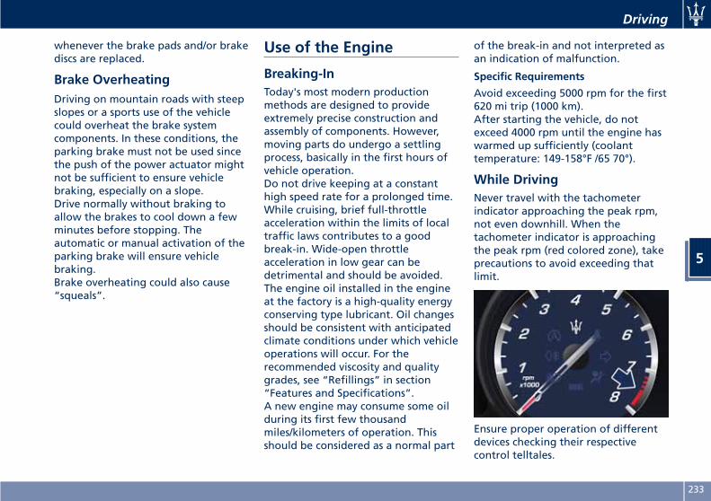
whenever the brake pads and/or brakediscs are replaced.
Brake OverheatingDriving on mountain roads with steepslopes or a sports use of the vehiclecould overheat the brake systemcomponents. In these conditions, theparking brake must not be used sincethe push of the power actuator mightnot be sufficient to ensure vehiclebraking, especially on a slope.Drive normally without braking toallow the brakes to cool down a fewminutes before stopping. Theautomatic or manual activation of theparking brake will ensure vehiclebraking.Brake overheating could also cause“squeals”.
Use of the Engine
Breaking-InToday's most modern productionmethods are designed to provideextremely precise construction andassembly of components. However,moving parts do undergo a settlingprocess, basically in the first hours ofvehicle operation.Do not drive keeping at a constanthigh speed rate for a prolonged time.While cruising, brief full-throttleacceleration within the limits of localtraffic laws contributes to a goodbreak-in. Wide-open throttleacceleration in low gear can bedetrimental and should be avoided.The engine oil installed in the engineat the factory is a high-quality energyconserving type lubricant. Oil changesshould be consistent with anticipatedclimate conditions under which vehicleoperations will occur. For therecommended viscosity and qualitygrades, see “Refillings” in section“Features and Specifications”.A new engine may consume some oilduring its first few thousandmiles/kilometers of operation. Thisshould be considered as a normal part
of the break-in and not interpreted asan indication of malfunction.
Specific Requirements
Avoid exceeding 5000 rpm for the first620 mi trip (1000 km).After starting the vehicle, do notexceed 4000 rpm until the engine haswarmed up sufficiently (coolanttemperature: 149-158°F /65 70°).
While DrivingNever travel with the tachometerindicator approaching the peak rpm,not even downhill. When thetachometer indicator is approachingthe peak rpm (red colored zone), takeprecautions to avoid exceeding thatlimit.
Ensure proper operation of differentdevices checking their respectivecontrol telltales.
Driving
5
233
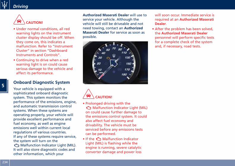
CAUTION!
• Under normal conditions, all redwarning lights on the instrumentcluster display should be off. Whenthey come on, this indicates amalfunction. Refer to “InstrumentCluster” in section “DashboardInstruments and Controls”.
• Continuing to drive when a redwarning light is on could causeserious damage to the vehicle andaffect its performance.
Onboard Diagnostic SystemYour vehicle is equipped with asophisticated onboard diagnosticsystem. This system monitors theperformance of the emissions, engine,and automatic transmission controlsystems. When these systems areoperating properly, your vehicle willprovide excellent performance andfuel economy, as well as engineemissions well within current localregulations of various countries.If any of these systems require service,the system will turn on the
Malfunction Indicator Light (MIL).It will also store diagnostic codes andother information, which your
Authorized Maserati Dealer will use toservice your vehicle. Although thevehicle will still be driveable and notneed towing, contact an AuthorizedMaserati Dealer for service as soon aspossible.
CAUTION!
• Prolonged driving with theMalfunction Indicator Light (MIL)
on could cause further damage tothe emissions control system. It couldalso affect fuel economy anddrivability. The vehicle must beserviced before any emissions testscan be performed.
• If the Malfunction IndicatorLight (MIL) is flashing while theengine is running, severe catalyticconverter damage and power loss
will soon occur. Immediate service isrequired at an Authorized MaseratiDealer.
• After the problem has been solved,the Authorized Maserati Dealerpersonnel will perform specific testsfor a complete check of the systemand, if necessary, road tests.
Driving
5
234
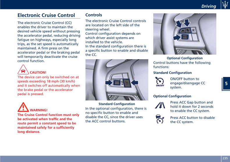
Electronic Cruise ControlThe electronic Cruise Control (CC)enables the driver to maintain thedesired vehicle speed without pressingthe accelerator pedal, reducing drivingfatigue on highways, especially longtrips, as the set speed is automaticallymaintained. A firm press on theaccelerator pedal or the braking pedalwill temporarily deactivate the cruisecontrol function.
CAUTION!The device can only be switched on atspeeds exceeding 18 mph (30 km/h)and it switches off automatically whenthe brake pedal or the acceleratorpedal is pressed.
WARNING!The Cruise Control function must onlybe activated when traffic and theroute permit a constant speed to bemaintained safely for a sufficientlylong distance.
ControlsThe electronic Cruise Control controlsare located on the left side of thesteering wheel.Control configuration depends onwhich driver assist systems areinstalled to the vehicle.In the standard configuration there isa specific button to enable and disablethe CC.
In the optional configuration, there isno specific button to enable anddisable the CC, since the driver usesthe ACC control buttons.
Control buttons have the followingfunctions:
Standard Configuration
ON/OFF button toengage/disengage CCsystem.
Optional Configuration
Press ACC Gap button andhold it down for 2 secondsto enable the CC system.
Press ACC button to disablethe CC system.
Standard Configuration
Optional Configuration
Driving
5
235
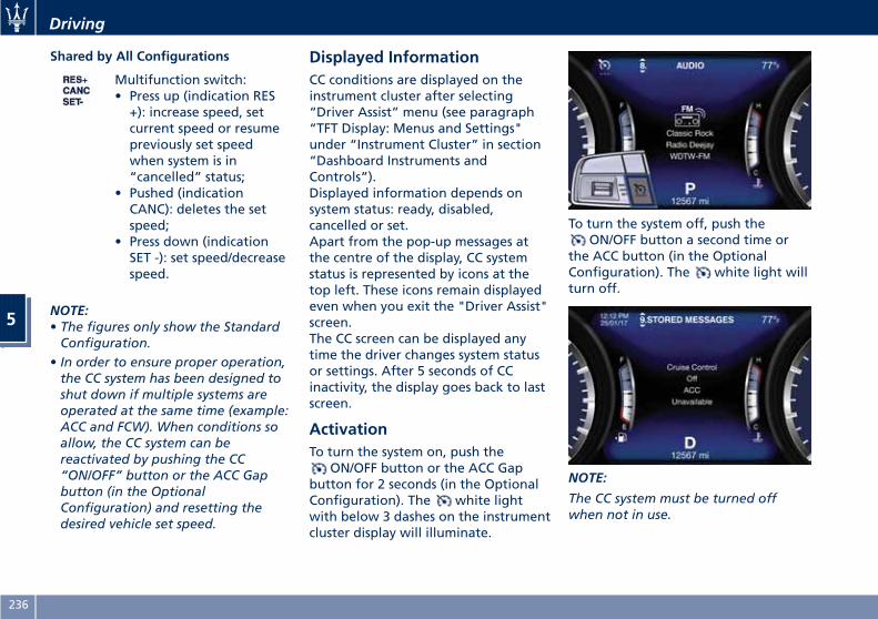
Shared by All Configurations
Multifunction switch:• Press up (indication RES+): increase speed, setcurrent speed or resumepreviously set speedwhen system is in“cancelled” status;
• Pushed (indicationCANC): deletes the setspeed;
• Press down (indicationSET -): set speed/decreasespeed.
NOTE:• The figures only show the StandardConfiguration.
• In order to ensure proper operation,the CC system has been designed toshut down if multiple systems areoperated at the same time (example:ACC and FCW). When conditions soallow, the CC system can bereactivated by pushing the CC“ON/OFF” button or the ACC Gapbutton (in the OptionalConfiguration) and resetting thedesired vehicle set speed.
Displayed InformationCC conditions are displayed on theinstrument cluster after selecting“Driver Assist” menu (see paragraph“TFT Display: Menus and Settings"under “Instrument Cluster” in section“Dashboard Instruments andControls”).Displayed information depends onsystem status: ready, disabled,cancelled or set.Apart from the pop-up messages atthe centre of the display, CC systemstatus is represented by icons at thetop left. These icons remain displayedeven when you exit the "Driver Assist"screen.The CC screen can be displayed anytime the driver changes system statusor settings. After 5 seconds of CCinactivity, the display goes back to lastscreen.
ActivationTo turn the system on, push the
ON/OFF button or the ACC Gapbutton for 2 seconds (in the OptionalConfiguration). The white lightwith below 3 dashes on the instrumentcluster display will illuminate.
To turn the system off, push theON/OFF button a second time or
the ACC button (in the OptionalConfiguration). The white light willturn off.
NOTE:
The CC system must be turned offwhen not in use.
Driving
5
236
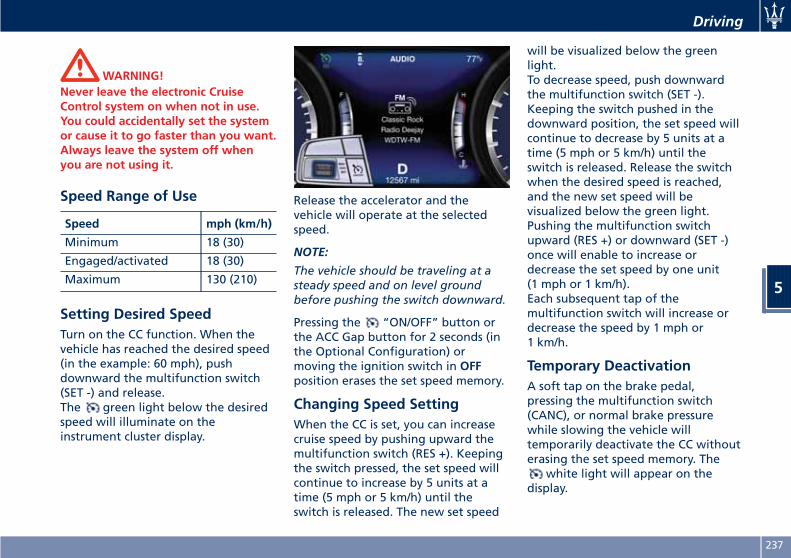
WARNING!Never leave the electronic CruiseControl system on when not in use.You could accidentally set the systemor cause it to go faster than you want.Always leave the system off whenyou are not using it.
Speed Range of Use
Speed mph (km/h)
Minimum 18 (30)
Engaged/activated 18 (30)
Maximum 130 (210)
Setting Desired SpeedTurn on the CC function. When thevehicle has reached the desired speed(in the example: 60 mph), pushdownward the multifunction switch(SET -) and release.The green light below the desiredspeed will illuminate on theinstrument cluster display.
Release the accelerator and thevehicle will operate at the selectedspeed.
NOTE:
The vehicle should be traveling at asteady speed and on level groundbefore pushing the switch downward.
Pressing the “ON/OFF” button orthe ACC Gap button for 2 seconds (inthe Optional Configuration) ormoving the ignition switch in OFFposition erases the set speed memory.
Changing Speed SettingWhen the CC is set, you can increasecruise speed by pushing upward themultifunction switch (RES +). Keepingthe switch pressed, the set speed willcontinue to increase by 5 units at atime (5 mph or 5 km/h) until theswitch is released. The new set speed
will be visualized below the greenlight.To decrease speed, push downwardthe multifunction switch (SET -).Keeping the switch pushed in thedownward position, the set speed willcontinue to decrease by 5 units at atime (5 mph or 5 km/h) until theswitch is released. Release the switchwhen the desired speed is reached,and the new set speed will bevisualized below the green light.Pushing the multifunction switchupward (RES +) or downward (SET -)once will enable to increase ordecrease the set speed by one unit(1 mph or 1 km/h).Each subsequent tap of themultifunction switch will increase ordecrease the speed by 1 mph or1 km/h.
Temporary DeactivationA soft tap on the brake pedal,pressing the multifunction switch(CANC), or normal brake pressurewhile slowing the vehicle willtemporarily deactivate the CC withouterasing the set speed memory. The
white light will appear on thedisplay.
Driving
5
237
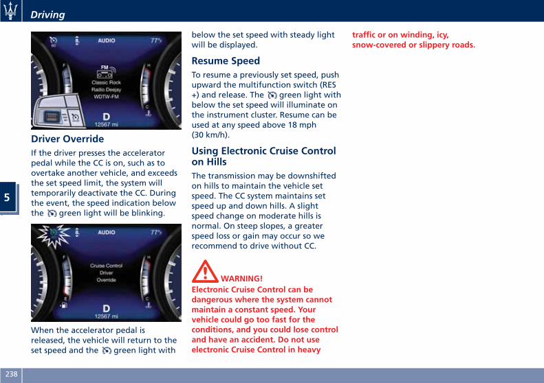
Driver OverrideIf the driver presses the acceleratorpedal while the CC is on, such as toovertake another vehicle, and exceedsthe set speed limit, the system willtemporarily deactivate the CC. Duringthe event, the speed indication belowthe green light will be blinking.
When the accelerator pedal isreleased, the vehicle will return to theset speed and the green light with
below the set speed with steady lightwill be displayed.
Resume SpeedTo resume a previously set speed, pushupward the multifunction switch (RES+) and release. The green light withbelow the set speed will illuminate onthe instrument cluster. Resume can beused at any speed above 18 mph(30 km/h).
Using Electronic Cruise Controlon HillsThe transmission may be downshiftedon hills to maintain the vehicle setspeed. The CC system maintains setspeed up and down hills. A slightspeed change on moderate hills isnormal. On steep slopes, a greaterspeed loss or gain may occur so werecommend to drive without CC.
WARNING!Electronic Cruise Control can bedangerous where the system cannotmaintain a constant speed. Yourvehicle could go too fast for theconditions, and you could lose controland have an accident. Do not useelectronic Cruise Control in heavy
traffic or on winding, icy,snow-covered or slippery roads.
Driving
5
238
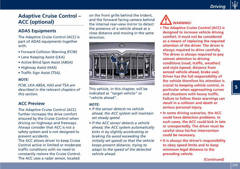
Adaptive Cruise Control –ACC (optional)
ADAS EquipmentsThe Adaptive Cruise Control (ACC) ispart of ADAS equipments togetherwith:
• Forward Collision Warning (FCW)• Lane Keeping Assist (LKA)• Active Blind Spot Assist (ABSA)• Highway Assist (HAS)• Traffic Sign Assist (TSA).
NOTE:
FCW, LKA ABSA, HAS and TSA aredescribed in the relevant chapters ofthis section.
ACC PreviewThe Adaptive Cruise Control (ACC)further increases the drive comfortensured by the Cruise Control whendriving on highways and freeways.Always consider that ACC is not asafety system and is not designed toprevent accidents.The ACC allows driver to keep CruiseControl active in limited or moderatetraffic conditions with no need toconstantly restore the Cruise Control.The ACC uses a radar sensor, located
on the front grille behind the trident,and the forward-facing camera behindthe internal rear-view mirror to detectthe presence of a vehicle ahead at aclose distance and moving in the samedirection.
This vehicle, in this chapter, will beindicated as "target vehicle" or"vehicle ahead".
NOTE:• If the sensor detects no vehicleahead, the ACC system will maintainset steady speed.
• If the ACC sensor detects a vehicleahead, the ACC system automaticallykicks in by slightly accelerating orbraking (to avoid exceeding theinitially set speed) so that the vehiclekeeps present distance, trying toadapt to the speed of the detectedvehicle ahead.
WARNING!• The Adaptive Cruise Control (ACC) isdesigned to increase vehicle drivingcomfort. It must not be consideredas a means of replacing the requiredattention of the driver. The driver isalways required to drive carefully.The driver is always required to payutmost attention to drivingconditions (road, traffic, weather)and style (speed, distance fromsensed vehicle ahead, brake use).Driver has the full responsibility ofthe vehicle therefore his attention iscrucial to keeping vehicle control, inparticular when approaching curvesand situations with heavy traffic.Failure to follow these warnings canresult in a collision and death orserious personal injury.
• In some driving scenarios, the ACCcould have detection problems. Insuch cases, the ACC could kick in lateor unexpectedly. The driver must becareful since his/her interventioncould be necessary.
• It is always the driver’s responsibilityto obey speed limits and to keepminimum legal distance to thepreceding vehicle.
(Continued)
Driving
5
239
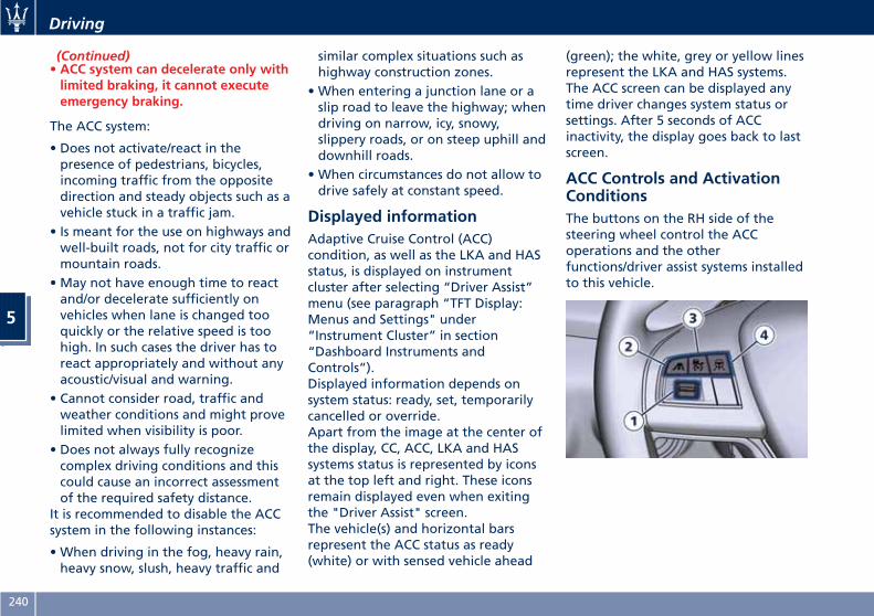
(Continued)• ACC system can decelerate only withlimited braking, it cannot executeemergency braking.
The ACC system:
• Does not activate/react in thepresence of pedestrians, bicycles,incoming traffic from the oppositedirection and steady objects such as avehicle stuck in a traffic jam.
• Is meant for the use on highways andwell-built roads, not for city traffic ormountain roads.
• May not have enough time to reactand/or decelerate sufficiently onvehicles when lane is changed tooquickly or the relative speed is toohigh. In such cases the driver has toreact appropriately and without anyacoustic/visual and warning.
• Cannot consider road, traffic andweather conditions and might provelimited when visibility is poor.
• Does not always fully recognizecomplex driving conditions and thiscould cause an incorrect assessmentof the required safety distance.
It is recommended to disable the ACCsystem in the following instances:
• When driving in the fog, heavy rain,heavy snow, slush, heavy traffic and
similar complex situations such ashighway construction zones.
• When entering a junction lane or aslip road to leave the highway; whendriving on narrow, icy, snowy,slippery roads, or on steep uphill anddownhill roads.
• When circumstances do not allow todrive safely at constant speed.
Displayed informationAdaptive Cruise Control (ACC)condition, as well as the LKA and HASstatus, is displayed on instrumentcluster after selecting “Driver Assist”menu (see paragraph “TFT Display:Menus and Settings" under“Instrument Cluster” in section“Dashboard Instruments andControls”).Displayed information depends onsystem status: ready, set, temporarilycancelled or override.Apart from the image at the center ofthe display, CC, ACC, LKA and HASsystems status is represented by iconsat the top left and right. These iconsremain displayed even when exitingthe "Driver Assist" screen.The vehicle(s) and horizontal barsrepresent the ACC status as ready(white) or with sensed vehicle ahead
(green); the white, grey or yellow linesrepresent the LKA and HAS systems.The ACC screen can be displayed anytime driver changes system status orsettings. After 5 seconds of ACCinactivity, the display goes back to lastscreen.
ACC Controls and ActivationConditionsThe buttons on the RH side of thesteering wheel control the ACCoperations and the otherfunctions/driver assist systems installedto this vehicle.
Driving
5
240
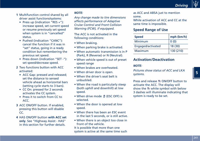
1 Multifunction control shared by alldriver assist functions/systems:• Press up (indication “RES +”):increase speed, set current speedor resume previously set speedwhen system is in “cancelled”status.
• Pushed (indication “CANC”):cancel the function if it was in“set” status, going in a readycondition but remembering theprevious set speed.
• Press down (indication “SET -”):set speed/decrease speed.
2 Two functions button with ACCactivated:• ACC Gap: pressed and released;set the distance to sensedvehicle ahead as horizontal bars(setting cycle starts to 3 bars).
• CC On: pressed for 2 secondsactivates the CC system.
• Press it to switch from CC toACC.
3 ACC ON/OFF button. If enabled,pressing this button will disableCC.
4 HAS ON/OFF button with ACC setonly. See "Highway Assist - HAS"in this section for further details.
NOTE:
Any change made to tire dimensionsaffects performance of AdaptiveCruise Control and Front CollisionWarning (FCW), if equipped.
The ACC is not activated in thefollowing conditions:
• When braking.• When parking brake is activated.• When automatic transmission is in P(Park), R (Reverse) or N (Neutral).
• When vehicle speed is out of presetspeed range
• When brakes are overheated.• When driver door is open.• When the driver’s seat belt isunbuckled.
• When the road is particularly steep(both uphill and downhill) at lowspeed.
• When drive mode (ESC OFF) isselected.
• When the door is opened at lowspeed.
• When there has been an ESC eventin the last 5 seconds, or is still active.
• When there is an object too close infront of the vehicle.
It is possible that more than onesystem is active at the same time such
as ACC and ABSA just to mentionsome.While activation of ACC and CC at thesame time is impossible.
Speed Range of Use
Speed mph (km/h)
Minimum 0 (0)
Engaged/activated 18 (30)
Maximum 130 (210)
Activation/Deactivation
NOTE:
Pictures show status of ACC and LKAsystems.
Press and release ON/OFF button toactivate the ACC. The display willshow the white symbol with below3 dashes will illuminate indicating thatsystem is ready to be set.
Driving
5
241
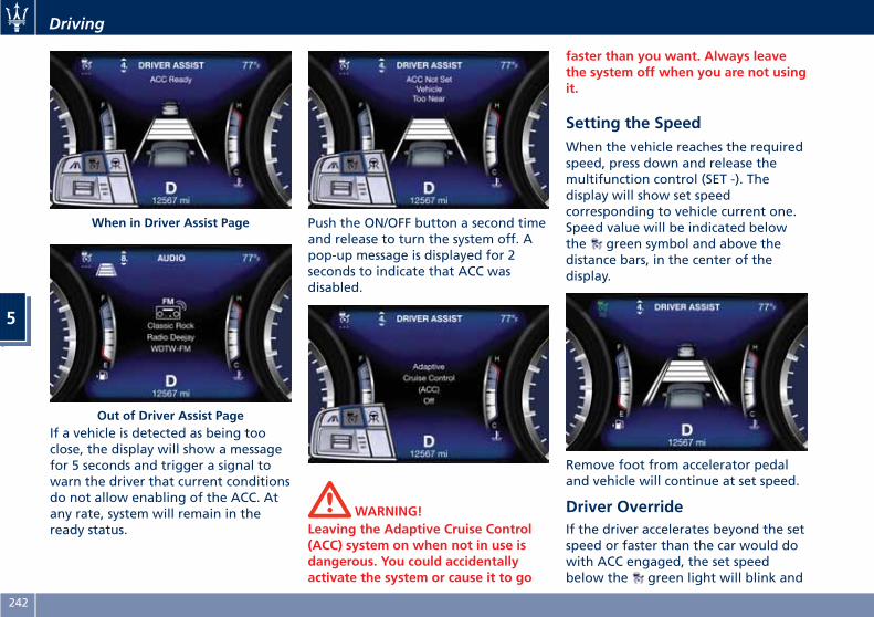
If a vehicle is detected as being tooclose, the display will show a messagefor 5 seconds and trigger a signal towarn the driver that current conditionsdo not allow enabling of the ACC. Atany rate, system will remain in theready status.
Push the ON/OFF button a second timeand release to turn the system off. Apop-up message is displayed for 2seconds to indicate that ACC wasdisabled.
WARNING!Leaving the Adaptive Cruise Control(ACC) system on when not in use isdangerous. You could accidentallyactivate the system or cause it to go
faster than you want. Always leavethe system off when you are not usingit.
Setting the SpeedWhen the vehicle reaches the requiredspeed, press down and release themultifunction control (SET -). Thedisplay will show set speedcorresponding to vehicle current one.Speed value will be indicated belowthe green symbol and above thedistance bars, in the center of thedisplay.
Remove foot from accelerator pedaland vehicle will continue at set speed.
Driver OverrideIf the driver accelerates beyond the setspeed or faster than the car would dowith ACC engaged, the set speedbelow the green light will blink and
When in Driver Assist Page
Out of Driver Assist Page
Driving
5
242
the time gap bars will vanish toindicate that in this condition thesystem cannot control the distancebetween vehicle and sensed vehicleahead. Vehicle speed will bedetermined only by the acceleratorpedal position.
Changing Speed SettingOnce speed is set, driver can increaseor decrease it by respectively pressingmultifunction control up (RES +) ordown (SET -). Speed can be increasedor decreased in two ways:
• Pressing control once, set speed willincrease or decrease by one unitcorresponding to 1 mph (1 km/h).
• Hold the control to increase ordecrease set speed by 5 mph(10 km/h) at a time.
NOTE:•When pressing the multifunctioncontrol up (RES +) or down (SET -),the new set speed will be the currentspeed of the vehicle.
•When using (SET -) control todecelerate, if the engine brakingpower does not slow down thevehicle sufficiently to reach the setspeed, the brake system willautomatically slow down the vehicle.
• The ACC system applies the brakedown to a full stop when followinga target vehicle. If an ACC hostvehicle follows a target vehicle to astandstill, after a two or threesecond delay, the system will not beable to resume driving the carautonomously. At this point it isnecessary for the driver to manuallyreengage the system by either usingthe multifunction control (press SET-or RES+) or by pressing theaccelerator pedal (see “ACCOperation Before and During Stop”in this chapter).
• The ACC system maintains set speedwhen driving up hill and down hill.However, a slight speed change onmoderate hills is normal. In addition,downshifting may occur whileclimbing uphill or descendingdownhill. This is normal operationand necessary to maintain set speed.When driving uphill and downhill,the ACC system will cancel if thebraking temperature exceeds normalrange.
Temporary DeactivationA soft tap on the brake pedal, pushingthe multifunction control (CANC), ornormal brake pressure while slowing
the vehicle will temporarily deactivatethe ACC without erasing the set speedmemory. The white light will appearon the display with below the setspeed.
Conditions for Disabling andDeactivationBesides the cases specified in theprevious paragraph, the followingconditions will disable the system:
• Anti-Lock Brake (ABS) kicks in.• Transmission lever is not in D (Drive).• The Electronic Stability Control andthe Traction Control System(ESC/TCS) activate.
• Vehicle parking brake is operated.• The driver safety belt is unbuckled atlow speed.
• The driver door is ajar at low speed.• The driver disabled the ESC using the
(ESC OFF) button on centralconsole.
• The road is too steep both uphill anddownhill at low speed.
The system is deactivated and setspeed is deleted from system memory,if the ACC ON/OFF button is pressed orif ignition device is turned to OFF.
Driving
5
243
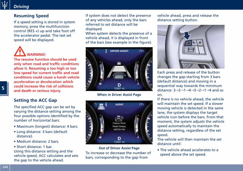
Resuming SpeedIf a speed setting is stored in systemmemory, press the multifunctioncontrol (RES +) up and take foot offthe accelerator pedal. The last setspeed will be displayed.
WARNING!The resume function should be usedonly when road and traffic conditionsallow it. Resuming a too high or toolow speed for current traffic and roadconditions could cause a harsh vehicleacceleration or deceleration whichcould increase the risk of collisionsand death or serious injury.
Setting the ACC GapThe specified ACC gap can be set byvarying the distance setting among thefour possible options identified by thenumber of horizontal bars:
• Maximum (longest) distance: 4 bars.• Long distance: 3 bars (defaultdistance).
• Medium distance: 2 bars.• Short distance: 1 bar.Using this distance setting and thevehicle speed, ACC calculates and setsthe gap to the vehicle ahead.
If system does not detect the presenceof any vehicles ahead, only the barsreferred to set distance will bedisplayed.When system detects the presence of avehicle ahead, it is displayed in frontof the bars (see example in the figure).
To increase or decrease the number ofbars, corresponding to the gap from
vehicle ahead, press and release thedistance setting button.
Each press and release of the buttonchanges the gap starting from 3 bars(default distance) and moving in asequential way towards the minimumdistance: 3→2→1→4→3→2→1→4 and soon.If there is no vehicle ahead, the vehiclewill maintain the set speed. If a slowermoving vehicle is detected in the samelane, the system displays the targetvehicle icon before the bars. From thatmoment, the system adjusts the vehiclespeed automatically to maintain thedistance setting, regardless of the setspeed.The vehicle will then maintain the setdistance until:
• The vehicle ahead accelerates to aspeed above the set speed.
When in Driver Assist Page
Out of Driver Assist Page
Driving
5
244
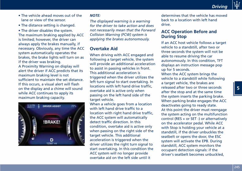
• The vehicle ahead moves out of thelane or view of the sensor.
• The distance setting is changed.• The driver disables the system.The maximum braking applied by ACCis limited; however, the driver canalways apply the brakes manually, ifnecessary. Obviously, any time the ACCsystem automatically operates thebrakes, the brake lights will turn on asif the driver was braking.A Proximity Warning on display willalert the driver if ACC predicts that itsmaximum braking level is notsufficient to maintain the set distance.If this occurs, a visual alert will flashon the display and a chime will soundwhile ACC continues to apply itsmaximum braking capacity.
NOTE:
The displayed warning is a warningfor the driver to take action and doesnot necessarily mean that the ForwardCollision Warning (FCW) system isapplying the brakes autonomously.
Overtake AidWhen driving with ACC engaged andfollowing a target vehicle, the systemwill provide an additional accelerationto assist in passing vehicles in front.This additional acceleration istriggered when the driver utilizes theleft turn signal to start overtaking. Inlocations with left hand drive traffic,overtake aid is active only whenpassing on the left hand side of thetarget vehicle.When a vehicle goes from a locationwith left hand drive traffic to alocation with right hand drive traffic,the ACC system will automaticallydetect traffic direction. In thiscondition, overtake aid is active onlywhen passing on the right side of thetarget vehicle. This additionalacceleration is triggered when thedriver utilizes the right turn signal tostart overtaking. In this condition theACC system will no longer provideovertake aid on the left side until it
determines that the vehicle has movedback to a location with left handdrive.
ACC Operation Before andDuring StopIf an ACC host vehicle follows a targetvehicle to a standstill, after two orthree seconds the system will not beable to resume driving the carautonomously. In this condition, TFTdisplays an instruction message popup for 5 seconds.When the ACC system brings thevehicle to a standstill while followinga target vehicle, the brakes arereleased after two or three secondsafter the stop and at the same timethe system inserts the parking brake.When parking brake engages the ACCdeactivates going to ready state.At this point the driver must reengagethe system acting on the multifunctioncontrol (RES + or SET -) or alternativelyon the accelerator pedal. While ACCwith Stop is holding your vehicle at astandstill, if the driver unbuckles theseatbelt or opens the door, the ESCsystem will activate the EPB. Duringstandstill, ACC system monitors theoccupant detection signals: if thedriver's seatbelt becomes unbuckled,
Driving
5
245
the ACC system shall be cancelledwhen the EPB is applied.
WARNING!When the ACC system is resumed, thedriver must ensure that there are nopedestrians, vehicles or objects in thepath of the vehicle. Failure to followthese warnings can result in a collisionand death or serious personal injury.
Display Warnings andMaintenance of ACC and FCWSystemsWipe Front Radar Sensor WarningThis warning will display and a signalwill indicate when conditionstemporarily limit system performancedue to sensor poor or failed signalreception. This most often occurs attimes of poor visibility, such as in snowor heavy rain. The ACC and FCWsystems may also become temporarilyblinded due to obstructions, such asmud, dirt or ice on the radar sensor. Inthese cases, the system will bedisabled.This message can sometimes bedisplayed while driving in highlyreflective areas (i.e. tunnels withreflective tiles, or ice and snow). The
ACC and FCW systems will recoveroperation after the vehicle has leftthese areas. Under rare conditions,when the radar is not tracking anyvehicles or objects in its path thiswarning may temporarily occur.If weather conditions are not a factor,the driver should examine the sensor.It may require cleaning or removal ofan obstruction. The sensor is located inthe center of the front grille, behindthe Maserati trident.To keep the ACC System operatingproperly, it is important to note thefollowing maintenance items:
• Always keep the sensor clean.Carefully wipe the sensor lens with asoft cloth. Be cautious not to damageit.
• Do not remove any screws from thesensor. Doing so could cause an ACCsystem malfunction or failure andrequire a sensor realignment.
• If the sensor or front end of thevehicle is damaged due to a collision,see your authorized dealer forservice.
• Do not attach or install anyaccessories near the sensor, includingtransparent material or aftermarketgrilles. Doing so could cause an ACCsystem failure or malfunction. When
the condition that deactivated thesystem is no longer present, thesystem will return to the “AdaptiveCruise Control Off” state and willresume function by simplyreactivating it.
NOTE:
If the radar sensor wipe warningmessage occurs frequently (e.g. morethan once on every trip) without anysnow, rain, mud, or other obstruction,have the radar sensor realigned at anAuthorized Maserati Dealer.
Clean Front Windshield WarningThis warning will display and a signalwill indicate when conditionstemporarily limit system performancedue to failed signal reception. Thismost often occurs at times of poorvisibility, such as in snow or heavy rainand fog. The ACC and FCW systemsmay also become temporarily blindeddue to obstructions, such as mud, dirt,or ice on the windshield and fog onthe inside of glass or when driving inbad weather. In these cases, the systemwill have degraded performance.The ACC and FCW systems will recoveroperation after the vehicle has leftthese areas. Under rare conditions,when the camera is not tracking any
Driving
5
246

vehicles or objects in its path thiswarning may temporarily occur.If weather conditions are not a factor,the driver should examine thewindshield and the camera. They mayrequire cleaning or removal of anobstruction.When the condition that createdlimited functionality is no longerpresent, the ACC and FCW systems willreturn to full functionality.
NOTE:
If the windshield wiper warningmessage occurs frequently (e.g. morethan once on every trip) without anysnow, rain, mud, or other obstruction,have the windshield andforward-facing camera inspected at anAuthorized Maserati Dealer.
Service ACC/FCW WarningIf the ACC and FCW systems turn off,and the system displays a servicewarning, there may be an internalsystem fault or a temporarymalfunction that limits functionality.Although the vehicle is still driveableunder normal conditions, ACC andFCW will be temporarily unavailable. Ifthis occurs, try activating ACC andFCW again later, following a key cycle.
If the problem persists, contact anAuthorized Maserati Dealer.
Precautions while Driving withACCOffset DrivingACC may not detect a vehicle in thesame lane that is offset from yourdirect line of travel, or a vehiclemerging in from a side lane. Theremay not be sufficient distance to thevehicle ahead. The offset vehicle maymove in and out of the line of travel,which can cause your vehicle to brakeor accelerate unexpectedly.
Turns and BendsWhen driving on a curve with ACCengaged, the system may decrease thevehicle speed and acceleration forstability reasons, with no targetvehicle detected. Once the vehicle isout of the curve the system willresume your original Set Speed. This isa part of normal ACC systemfunctionality. Moreover, the radarsensor might detect a vehicle on anearby lane or no longer detect thetarget vehicle.
Driving
5
247
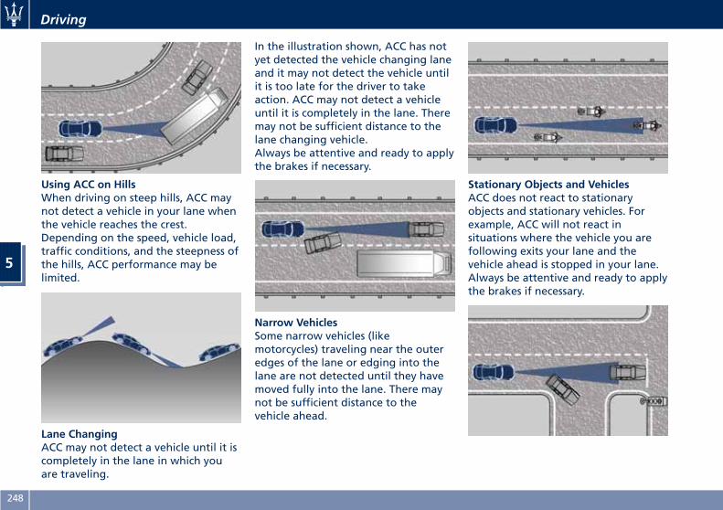
Using ACC on HillsWhen driving on steep hills, ACC maynot detect a vehicle in your lane whenthe vehicle reaches the crest.Depending on the speed, vehicle load,traffic conditions, and the steepness ofthe hills, ACC performance may belimited.
Lane ChangingACC may not detect a vehicle until it iscompletely in the lane in which youare traveling.
In the illustration shown, ACC has notyet detected the vehicle changing laneand it may not detect the vehicle untilit is too late for the driver to takeaction. ACC may not detect a vehicleuntil it is completely in the lane. Theremay not be sufficient distance to thelane changing vehicle.Always be attentive and ready to applythe brakes if necessary.
Narrow VehiclesSome narrow vehicles (likemotorcycles) traveling near the outeredges of the lane or edging into thelane are not detected until they havemoved fully into the lane. There maynot be sufficient distance to thevehicle ahead.
Stationary Objects and VehiclesACC does not react to stationaryobjects and stationary vehicles. Forexample, ACC will not react insituations where the vehicle you arefollowing exits your lane and thevehicle ahead is stopped in your lane.Always be attentive and ready to applythe brakes if necessary.
Driving
5
248
Radar Device - ComplianceStatementThis device complies with Part 15 ofthe FCC Rules (NF3-LRR4).Operation is subject to the followingtwo conditions:
• this device may not cause harmfulinterference, and
• this device must accept anyinterference received, includinginterference that may causeundesired operation.
Any unauthorized modifications orchanges to these devices could voidthe authority of the user to operatethis equipment.This equipment has been tested andfound to comply with the limits for aClass A digital device, pursuant to Part15 of the FCC Rules. These limits aredesigned to provide reasonableprotection against harmfulinterference when the equipment isoperated in a commercialenvironment. This equipmentgenerates, uses, and can radiate radiofrequency energy and, if not installedand used in accordance with theinstruction manual, may cause harmfulinterference to radio communications.Operation of this equipment in aresidential area is likely to cause
harmful interference in which case theuser will be required to correct theinterference at his own expense.
Radiofrequency Radiation ExposureInformationThis equipment complies with FCCradiation exposure limits set forth foran uncontrolled environment. Thisequipment should be installed andoperated with minimum distance of7.8 in (20 cm) between the radiatorand your body.This transmitter must not beco-located or operating in conjunctionwith any other antenna or transmitter.
Forward Collision Warning– FCW (optional, with ACConly)
OperationThe Forward Collision Warning (FCW)system with braking action interactswith the Adaptive Cruise Control(ACC), uses the same parts for sensingvehicle ahead (hereinafter “targetvehicle”) as well as part of thewarnings/messages on systemcondition and activation status. Forfurther details, refer to “AdaptiveCruise Control - ACC” in this section.Full performance can be reached onlywhen both the sensing parts havedetected the object, the differencebetween full and reducedperformance is not visible for thedriver.The FCW provides audible and visualwarnings when a potential collision isdetected. Brake actuation and limitedbraking may also be applieddepending on the specific scenario.
NOTE:
FCW system is not intended fortowing: this could lead the system tomalfunctions and/or to late reaction.
Driving
5
249
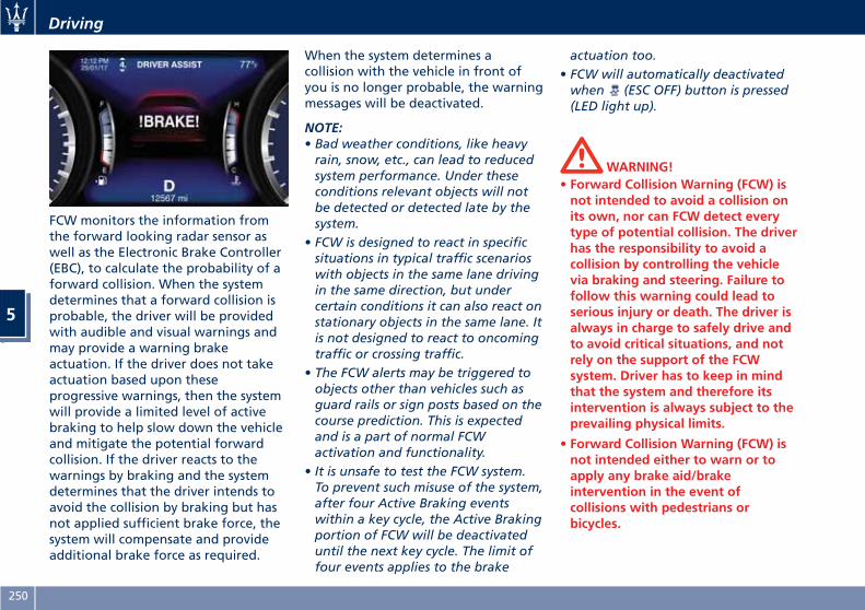
FCW monitors the information fromthe forward looking radar sensor aswell as the Electronic Brake Controller(EBC), to calculate the probability of aforward collision. When the systemdetermines that a forward collision isprobable, the driver will be providedwith audible and visual warnings andmay provide a warning brakeactuation. If the driver does not takeactuation based upon theseprogressive warnings, then the systemwill provide a limited level of activebraking to help slow down the vehicleand mitigate the potential forwardcollision. If the driver reacts to thewarnings by braking and the systemdetermines that the driver intends toavoid the collision by braking but hasnot applied sufficient brake force, thesystem will compensate and provideadditional brake force as required.
When the system determines acollision with the vehicle in front ofyou is no longer probable, the warningmessages will be deactivated.
NOTE:• Bad weather conditions, like heavyrain, snow, etc., can lead to reducedsystem performance. Under theseconditions relevant objects will notbe detected or detected late by thesystem.
• FCW is designed to react in specificsituations in typical traffic scenarioswith objects in the same lane drivingin the same direction, but undercertain conditions it can also react onstationary objects in the same lane. Itis not designed to react to oncomingtraffic or crossing traffic.
• The FCW alerts may be triggered toobjects other than vehicles such asguard rails or sign posts based on thecourse prediction. This is expectedand is a part of normal FCWactivation and functionality.
• It is unsafe to test the FCW system.To prevent such misuse of the system,after four Active Braking eventswithin a key cycle, the Active Brakingportion of FCW will be deactivateduntil the next key cycle. The limit offour events applies to the brake
actuation too.• FCW will automatically deactivatedwhen (ESC OFF) button is pressed(LED light up).
WARNING!• Forward Collision Warning (FCW) isnot intended to avoid a collision onits own, nor can FCW detect everytype of potential collision. The driverhas the responsibility to avoid acollision by controlling the vehiclevia braking and steering. Failure tofollow this warning could lead toserious injury or death. The driver isalways in charge to safely drive andto avoid critical situations, and notrely on the support of the FCWsystem. Driver has to keep in mindthat the system and therefore itsintervention is always subject to theprevailing physical limits.
• Forward Collision Warning (FCW) isnot intended either to warn or toapply any brake aid/brakeintervention in the event ofcollisions with pedestrians orbicycles.
Driving
5
250
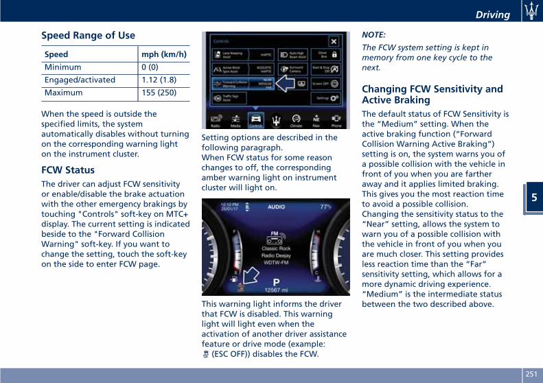
Speed Range of Use
Speed mph (km/h)
Minimum 0 (0)
Engaged/activated 1.12 (1.8)
Maximum 155 (250)
When the speed is outside thespecified limits, the systemautomatically disables without turningon the corresponding warning lighton the instrument cluster.
FCW StatusThe driver can adjust FCW sensitivityor enable/disable the brake actuationwith the other emergency brakings bytouching "Controls" soft-key on MTC+display. The current setting is indicatedbeside to the "Forward CollisionWarning" soft-key. If you want tochange the setting, touch the soft-keyon the side to enter FCW page.
Setting options are described in thefollowing paragraph.When FCW status for some reasonchanges to off, the correspondingamber warning light on instrumentcluster will light on.
This warning light informs the driverthat FCW is disabled. This warninglight will light even when theactivation of another driver assistancefeature or drive mode (example:
(ESC OFF)) disables the FCW.
NOTE:
The FCW system setting is kept inmemory from one key cycle to thenext.
Changing FCW Sensitivity andActive BrakingThe default status of FCW Sensitivity isthe “Medium” setting. When theactive braking function (“ForwardCollision Warning Active Braking”)setting is on, the system warns you ofa possible collision with the vehicle infront of you when you are fartheraway and it applies limited braking.This gives you the most reaction timeto avoid a possible collision.Changing the sensitivity status to the“Near” setting, allows the system towarn you of a possible collision withthe vehicle in front of you when youare much closer. This setting providesless reaction time than the “Far”sensitivity setting, which allows for amore dynamic driving experience.“Medium” is the intermediate statusbetween the two described above.
Driving
5
251
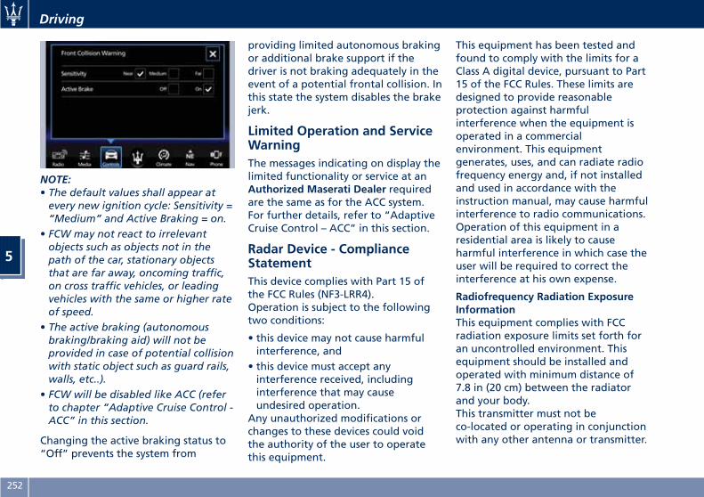
NOTE:• The default values shall appear atevery new ignition cycle: Sensitivity =“Medium” and Active Braking = on.
• FCW may not react to irrelevantobjects such as objects not in thepath of the car, stationary objectsthat are far away, oncoming traffic,on cross traffic vehicles, or leadingvehicles with the same or higher rateof speed.
• The active braking (autonomousbraking/braking aid) will not beprovided in case of potential collisionwith static object such as guard rails,walls, etc..).
• FCW will be disabled like ACC (referto chapter “Adaptive Cruise Control -ACC” in this section.
Changing the active braking status to“Off” prevents the system from
providing limited autonomous brakingor additional brake support if thedriver is not braking adequately in theevent of a potential frontal collision. Inthis state the system disables the brakejerk.
Limited Operation and ServiceWarningThe messages indicating on display thelimited functionality or service at anAuthorized Maserati Dealer requiredare the same as for the ACC system.For further details, refer to “AdaptiveCruise Control – ACC” in this section.
Radar Device - ComplianceStatementThis device complies with Part 15 ofthe FCC Rules (NF3-LRR4).Operation is subject to the followingtwo conditions:
• this device may not cause harmfulinterference, and
• this device must accept anyinterference received, includinginterference that may causeundesired operation.
Any unauthorized modifications orchanges to these devices could voidthe authority of the user to operatethis equipment.
This equipment has been tested andfound to comply with the limits for aClass A digital device, pursuant to Part15 of the FCC Rules. These limits aredesigned to provide reasonableprotection against harmfulinterference when the equipment isoperated in a commercialenvironment. This equipmentgenerates, uses, and can radiate radiofrequency energy and, if not installedand used in accordance with theinstruction manual, may cause harmfulinterference to radio communications.Operation of this equipment in aresidential area is likely to causeharmful interference in which case theuser will be required to correct theinterference at his own expense.
Radiofrequency Radiation ExposureInformationThis equipment complies with FCCradiation exposure limits set forth foran uncontrolled environment. Thisequipment should be installed andoperated with minimum distance of7.8 in (20 cm) between the radiatorand your body.This transmitter must not beco-located or operating in conjunctionwith any other antenna or transmitter.
Driving
5
252
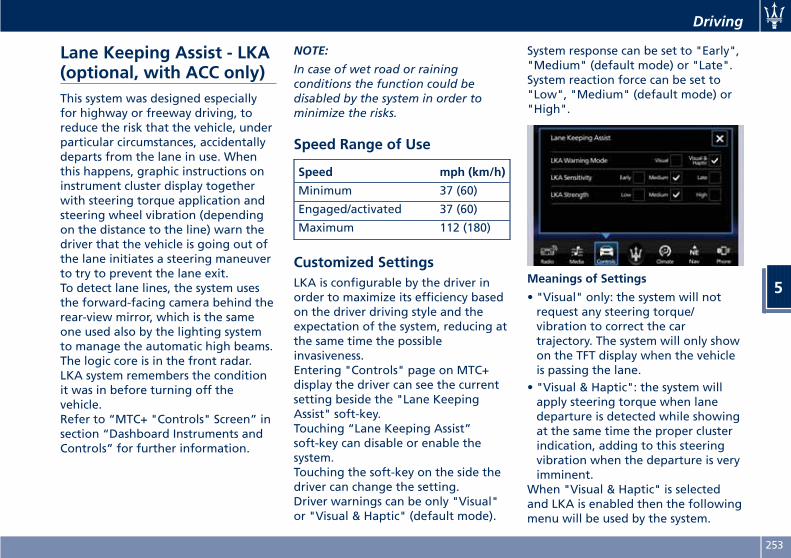
Lane Keeping Assist - LKA(optional, with ACC only)This system was designed especiallyfor highway or freeway driving, toreduce the risk that the vehicle, underparticular circumstances, accidentallydeparts from the lane in use. Whenthis happens, graphic instructions oninstrument cluster display togetherwith steering torque application andsteering wheel vibration (dependingon the distance to the line) warn thedriver that the vehicle is going out ofthe lane initiates a steering maneuverto try to prevent the lane exit.To detect lane lines, the system usesthe forward-facing camera behind therear-view mirror, which is the sameone used also by the lighting systemto manage the automatic high beams.The logic core is in the front radar.LKA system remembers the conditionit was in before turning off thevehicle.Refer to “MTC+ "Controls" Screen” insection “Dashboard Instruments andControls” for further information.
NOTE:
In case of wet road or rainingconditions the function could bedisabled by the system in order tominimize the risks.
Speed Range of Use
Speed mph (km/h)
Minimum 37 (60)
Engaged/activated 37 (60)
Maximum 112 (180)
Customized SettingsLKA is configurable by the driver inorder to maximize its efficiency basedon the driver driving style and theexpectation of the system, reducing atthe same time the possibleinvasiveness.Entering "Controls" page on MTC+display the driver can see the currentsetting beside the "Lane KeepingAssist" soft-key.Touching “Lane Keeping Assist”soft-key can disable or enable thesystem.Touching the soft-key on the side thedriver can change the setting.Driver warnings can be only "Visual"or "Visual & Haptic" (default mode).
System response can be set to "Early","Medium" (default mode) or "Late".System reaction force can be set to"Low", "Medium" (default mode) or"High".
Meanings of Settings
• "Visual" only: the system will notrequest any steering torque/vibration to correct the cartrajectory. The system will only showon the TFT display when the vehicleis passing the lane.
• "Visual & Haptic": the system willapply steering torque when lanedeparture is detected while showingat the same time the proper clusterindication, adding to this steeringvibration when the departure is veryimminent.
When "Visual & Haptic" is selectedand LKA is enabled then the followingmenu will be used by the system.
Driving
5
253
• "LKA Sensitivity": it tunes thedistance to the lane boundary wherethe system will start to apply steeringtorque.
• "LKA Strength": it tunes the steeringtorque value to have a stronger orweaker trajectory correction/deviation.
WARNING!In rare cases, Lane Keeping Assist(LKA) may make an inappropriatesteering torque application. LKA maybe interrupted at any time countersteering. Lack of attention may lead toserious injury or death.
System AvailabilityThe ADAS systems (LKA, CC, ACC, FCWand HAS) help the driver while driving.These systems can be set andmonitored simultaneously on thedisplay, after opening “Driver Assist”menu (see paragraph “TFT Display:Menus and Settings” under“Instrument Cluster” in section“Dashboard Instruments andControls”).LKA is designed for an attentive driver;therefore the system is available onlywhen his/her hands are on the steering
wheel or with hands off for only alimited amount of time. When thesystem is enabled it will trigger clusterwarning in case at least one hand isnot detected on the steering wheel.The torque application as well as thevibration are suppressed/inhibited incase of: high driver torque in thesteering wheel, high lateralacceleration, hands not on the steeringwheel detected for more than acertain time.High dynamic driving behaviors,driving on the lane boundary, ordriving off course will prevent thefunction from working. FCW brakingand stability system interventions (ESC,ABS) will also prevent the system fromoperating. Changing lanes results insystem inhibition for a certain time. Inaddition, the driver must respect someroad characteristics such asminimum-maximum width, lanesclearly defined by two lane boundariesand, only in limited cases and for alimited time, at least one laneboundary.
NOTE:
• In case of wet road or rainingconditions the function could bedisabled by the system in order tominimize the risks.
•With lane boundaries it is mainlyreferred to painted lines,nevertheless the system in goodconditions might properly recognizeas valid lane boundaries also othertypes (for example road edges, curbs,etc..).
Being this function used to preventunintentional lane change/lane drift, itwill be temporary suppressed/inhibitedby a turn indicator activation,therefore, graphic warning, steeringtorque application and vibration willbe terminated. In this condition in caseof a vehicle detected by the Blind SpotAssist (BSA) system in the covered areaon the proper side, there can be thetransition from LKA to Active BlindSpot Assist (ABSA) (if this latter is onand properly configured).
Function Description andOperating ModeThe intent of the function is to preventthe lane departure by warning thedriver through indication on thecluster and, if set, applying steeringtorque and vibration. Whenever thesystem is enabled there will be graphicon the dedicated screen in the driverassist page and for the others it will beavailable in the left top corner of the
Driving
5
254
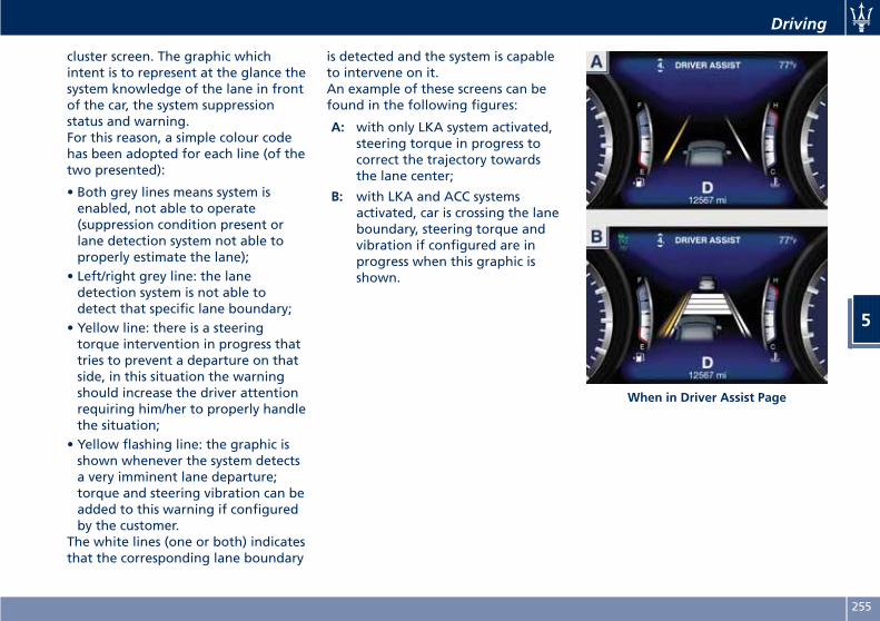
cluster screen. The graphic whichintent is to represent at the glance thesystem knowledge of the lane in frontof the car, the system suppressionstatus and warning.For this reason, a simple colour codehas been adopted for each line (of thetwo presented):
• Both grey lines means system isenabled, not able to operate(suppression condition present orlane detection system not able toproperly estimate the lane);
• Left/right grey line: the lanedetection system is not able todetect that specific lane boundary;
• Yellow line: there is a steeringtorque intervention in progress thattries to prevent a departure on thatside, in this situation the warningshould increase the driver attentionrequiring him/her to properly handlethe situation;
• Yellow flashing line: the graphic isshown whenever the system detectsa very imminent lane departure;torque and steering vibration can beadded to this warning if configuredby the customer.
The white lines (one or both) indicatesthat the corresponding lane boundary
is detected and the system is capableto intervene on it.An example of these screens can befound in the following figures:
A: with only LKA system activated,steering torque in progress tocorrect the trajectory towardsthe lane center;
B: with LKA and ACC systemsactivated, car is crossing the laneboundary, steering torque andvibration if configured are inprogress when this graphic isshown.
When in Driver Assist Page
Driving
5
255
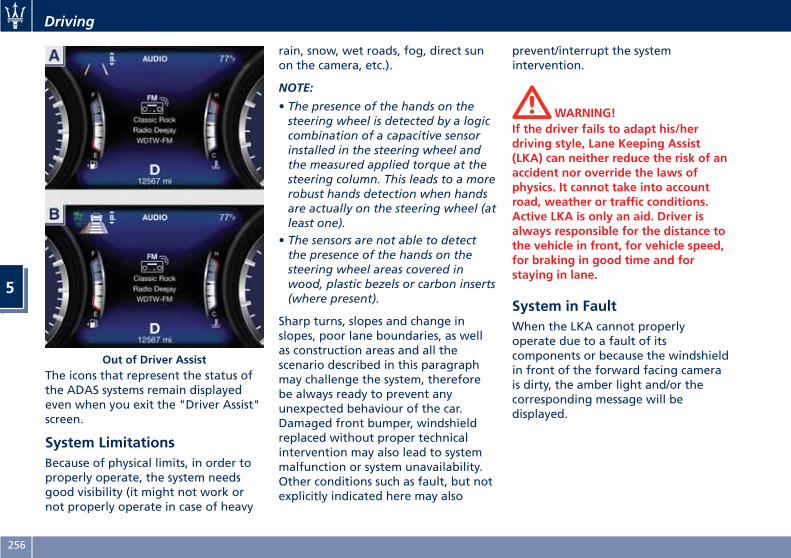
The icons that represent the status ofthe ADAS systems remain displayedeven when you exit the "Driver Assist"screen.
System LimitationsBecause of physical limits, in order toproperly operate, the system needsgood visibility (it might not work ornot properly operate in case of heavy
rain, snow, wet roads, fog, direct sunon the camera, etc.).
NOTE:
• The presence of the hands on thesteering wheel is detected by a logiccombination of a capacitive sensorinstalled in the steering wheel andthe measured applied torque at thesteering column. This leads to a morerobust hands detection when handsare actually on the steering wheel (atleast one).
• The sensors are not able to detectthe presence of the hands on thesteering wheel areas covered inwood, plastic bezels or carbon inserts(where present).
Sharp turns, slopes and change inslopes, poor lane boundaries, as wellas construction areas and all thescenario described in this paragraphmay challenge the system, thereforebe always ready to prevent anyunexpected behaviour of the car.Damaged front bumper, windshieldreplaced without proper technicalintervention may also lead to systemmalfunction or system unavailability.Other conditions such as fault, but notexplicitly indicated here may also
prevent/interrupt the systemintervention.
WARNING!If the driver fails to adapt his/herdriving style, Lane Keeping Assist(LKA) can neither reduce the risk of anaccident nor override the laws ofphysics. It cannot take into accountroad, weather or traffic conditions.Active LKA is only an aid. Driver isalways responsible for the distance tothe vehicle in front, for vehicle speed,for braking in good time and forstaying in lane.
System in FaultWhen the LKA cannot properlyoperate due to a fault of itscomponents or because the windshieldin front of the forward facing camerais dirty, the amber light and/or thecorresponding message will bedisplayed.
Out of Driver Assist
Driving
5
256
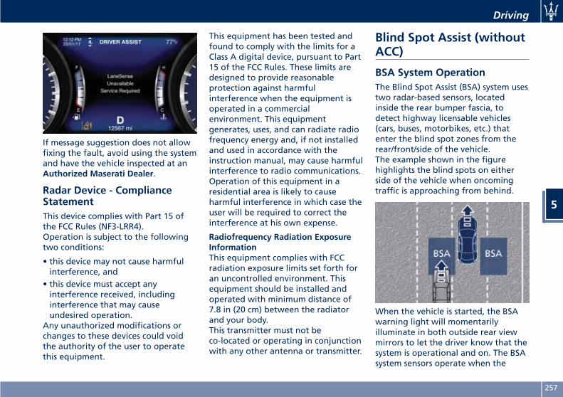
If message suggestion does not allowfixing the fault, avoid using the systemand have the vehicle inspected at anAuthorized Maserati Dealer.
Radar Device - ComplianceStatementThis device complies with Part 15 ofthe FCC Rules (NF3-LRR4).Operation is subject to the followingtwo conditions:
• this device may not cause harmfulinterference, and
• this device must accept anyinterference received, includinginterference that may causeundesired operation.
Any unauthorized modifications orchanges to these devices could voidthe authority of the user to operatethis equipment.
This equipment has been tested andfound to comply with the limits for aClass A digital device, pursuant to Part15 of the FCC Rules. These limits aredesigned to provide reasonableprotection against harmfulinterference when the equipment isoperated in a commercialenvironment. This equipmentgenerates, uses, and can radiate radiofrequency energy and, if not installedand used in accordance with theinstruction manual, may cause harmfulinterference to radio communications.Operation of this equipment in aresidential area is likely to causeharmful interference in which case theuser will be required to correct theinterference at his own expense.
Radiofrequency Radiation ExposureInformationThis equipment complies with FCCradiation exposure limits set forth foran uncontrolled environment. Thisequipment should be installed andoperated with minimum distance of7.8 in (20 cm) between the radiatorand your body.This transmitter must not beco-located or operating in conjunctionwith any other antenna or transmitter.
Blind Spot Assist (withoutACC)
BSA System OperationThe Blind Spot Assist (BSA) system usestwo radar-based sensors, locatedinside the rear bumper fascia, todetect highway licensable vehicles(cars, buses, motorbikes, etc.) thatenter the blind spot zones from therear/front/side of the vehicle.The example shown in the figurehighlights the blind spots on eitherside of the vehicle when oncomingtraffic is approaching from behind.
When the vehicle is started, the BSAwarning light will momentarilyilluminate in both outside rear viewmirrors to let the driver know that thesystem is operational and on. The BSAsystem sensors operate when the
Driving
5
257
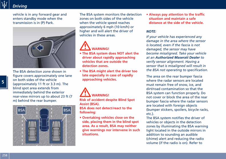
vehicle is in any forward gear andenters standby mode when thetransmission is in (P) Park.
The BSA detection zone shown infigure covers approximately one laneon both sides of the vehicle(approximately 11 ft or 3.3 m). Theblind spot area extends fromimmediately behind the exteriorrear-view mirrors up to about 23 ft (7m) behind the rear bumper.
The BSA system monitors the detectionzones on both sides of the vehiclewhen the vehicle speed reachesapproximately 6 mph (10 km/h) orhigher and will alert the driver ofvehicles in these areas.
WARNING!• The BSA system does NOT alert thedriver about rapidly approachingvehicles that are outside thedetection zones.
• The BSA might alert the driver toolate especially in case of rapidlyapproaching vehicles.
WARNING!Risk of accident despite Blind SpotAssist (BSA).BSA does not detect/react to thefollowing:
• Overtaking vehicles close on theside, placing them in the blind spotarea. As a result, BSA may neithergive warnings nor intervene in suchsituations.
• Always pay attention to the trafficsituation and maintain a safedistance at the side of the vehicle.
NOTE:
If your vehicle has experienced anydamage in the area where the sensoris located, even if the fascia is notdamaged, the sensor may havebecome misaligned. Take your vehicleat an Authorized Maserati Dealer toverify sensor alignment. Having asensor that is misaligned will result inthe BSA not operating to specification.
The area on the rear bumper fasciawhere the radar sensors are locatedmust remain free of snow, ice, anddirt/road contamination so that theBSA system can function properly. Donot cover or block the area of the rearbumper fascia where the radar sensorsare located with foreign objects(bumper stickers, spoilers, bicycle racks,etc.).The BSA system notifies the driver ofvehicles or objects in the detectionzones by illuminating the BSA warninglight located in the outside mirrors inaddition to sounding an audible(chime) alert and reducing the radiovolume (if the radio is on). Refer to
Driving
5
258
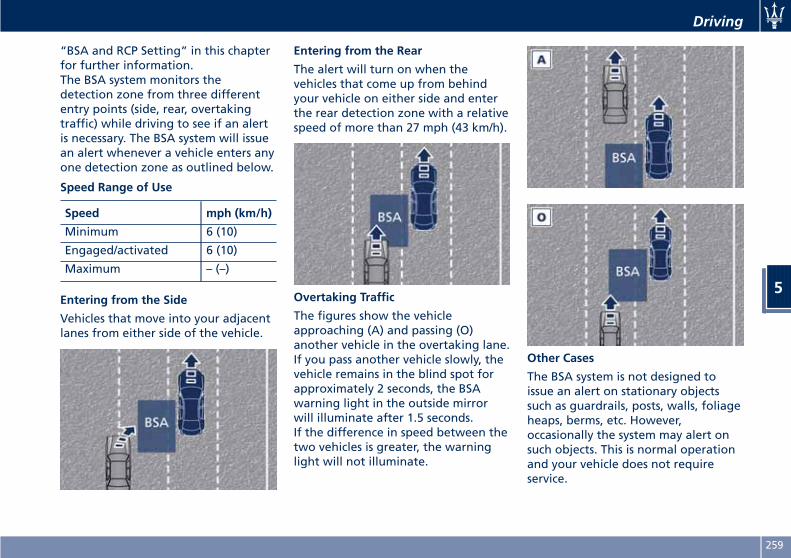
“BSA and RCP Setting” in this chapterfor further information.The BSA system monitors thedetection zone from three differententry points (side, rear, overtakingtraffic) while driving to see if an alertis necessary. The BSA system will issuean alert whenever a vehicle enters anyone detection zone as outlined below.
Speed Range of Use
Speed mph (km/h)
Minimum 6 (10)
Engaged/activated 6 (10)
Maximum – (–)
Entering from the Side
Vehicles that move into your adjacentlanes from either side of the vehicle.
Entering from the Rear
The alert will turn on when thevehicles that come up from behindyour vehicle on either side and enterthe rear detection zone with a relativespeed of more than 27 mph (43 km/h).
Overtaking Traffic
The figures show the vehicleapproaching (A) and passing (O)another vehicle in the overtaking lane.If you pass another vehicle slowly, thevehicle remains in the blind spot forapproximately 2 seconds, the BSAwarning light in the outside mirrorwill illuminate after 1.5 seconds.If the difference in speed between thetwo vehicles is greater, the warninglight will not illuminate.
Other Cases
The BSA system is not designed toissue an alert on stationary objectssuch as guardrails, posts, walls, foliageheaps, berms, etc. However,occasionally the system may alert onsuch objects. This is normal operationand your vehicle does not requireservice.
Driving
5
259
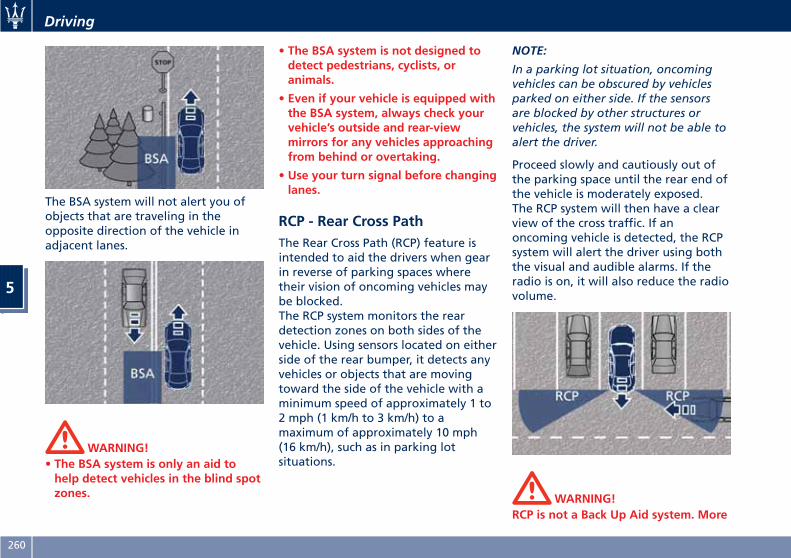
The BSA system will not alert you ofobjects that are traveling in theopposite direction of the vehicle inadjacent lanes.
WARNING!• The BSA system is only an aid tohelp detect vehicles in the blind spotzones.
• The BSA system is not designed todetect pedestrians, cyclists, oranimals.
• Even if your vehicle is equipped withthe BSA system, always check yourvehicle’s outside and rear-viewmirrors for any vehicles approachingfrom behind or overtaking.
• Use your turn signal before changinglanes.
RCP - Rear Cross PathThe Rear Cross Path (RCP) feature isintended to aid the drivers when gearin reverse of parking spaces wheretheir vision of oncoming vehicles maybe blocked.The RCP system monitors the reardetection zones on both sides of thevehicle. Using sensors located on eitherside of the rear bumper, it detects anyvehicles or objects that are movingtoward the side of the vehicle with aminimum speed of approximately 1 to2 mph (1 km/h to 3 km/h) to amaximum of approximately 10 mph(16 km/h), such as in parking lotsituations.
NOTE:
In a parking lot situation, oncomingvehicles can be obscured by vehiclesparked on either side. If the sensorsare blocked by other structures orvehicles, the system will not be able toalert the driver.
Proceed slowly and cautiously out ofthe parking space until the rear end ofthe vehicle is moderately exposed.The RCP system will then have a clearview of the cross traffic. If anoncoming vehicle is detected, the RCPsystem will alert the driver using boththe visual and audible alarms. If theradio is on, it will also reduce the radiovolume.
WARNING!RCP is not a Back Up Aid system. More
Driving
5
260
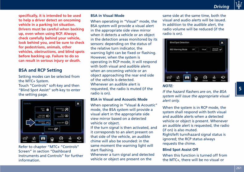
specifically, it is intended to be usedto help a driver detect an oncomingvehicle in a parking lot situation.Drivers must be careful when backingup, even when using RCP. Alwayscheck carefully behind your vehicle,look behind you, and be sure to checkfor pedestrians, animals, othervehicles, obstructions, and blind spotsbefore backing up. Failure to do socan result in serious injury or death.
BSA and RCP SettingSetting modes can be selected fromthe MTC+ System.Touch “Controls” soft-key and then“Blind Spot Assist” soft-key to enterthe setting page.
Refer to chapter “MTC+ “Controls”Screen” in section “DashboardInstruments and Controls” for furtherinformation.
BSA in Visual Mode
When operating in “Visual” mode, theBSA system will provide a visual alertin the appropriate side view mirrorwhen it detects a vehicle or an objectin the detection areas monitored by itssensors: depending on the status ofthe relative turn indicator, thewarning light can be fixed or flashing.However, when the system isoperating in RCP mode, it will respondwith both visual and audible alertswhen an oncoming vehicle or anobject approaching the rear end sideof the vehicle is detected.Whenever an audible alert isrequested, the radio is muted (if theradio is on).
BSA in Visual and Acoustic Mode
When operating in “Visual & Acoustic”mode, the BSA system will provide avisual alert in the appropriate sideview mirror based on a detectedvehicle or object.If the turn signal is then activated, andit corresponds to an alert present onthat side of the vehicle, an audiblechime will also be sounded: in thesame moment the warning light willstart flashing.Whenever a turn signal and detectedvehicle or object are present on the
same side at the same time, both thevisual and audio alerts will be issued.In addition to the audible alert, theradio volume will be reduced (if theradio is on).
NOTE:
If the hazard flashers are on, the BSAsystem will issue the appropriate visualalert only.
When the system is in RCP mode, thesystem shall respond with both visualand audible alerts when a detectedvehicle or object is present. Wheneveran audible alert is requested, the radio(if on) is also muted.Right/left turn/hazard signal status isignored; the RCP status alwaysrequests the chime.
Blind Spot Assist Off
When this function is turned off fromthe MTC+, there will be no visual or
Driving
5
261
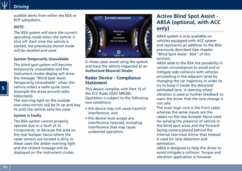
audible alerts from either the BSA orRCP subsystems.
NOTE:
The BSA system will store the currentoperating mode when the vehicle isshut off. Each time the vehicle isstarted, the previously-stored modewill be recalled and used.
System Temporarily Unavailable
The blind spot system will becometemporarily unavailable and theinstrument cluster display will showthe message “Blind Spot AssistTemporarily Unavailable” when thevehicle enters a radio quite zone(example the areas around radiotelescopes).The warning light on the outsiderear-view mirrors will be lit up and staylit until the vehicle exits the zone.
System is Faulty
The BSA system cannot properlyoperate due to a fault of itscomponents, or because the area onthe rear bumper fascia where theradar sensors are located is dirty. Inthese cases the amber warning lightand the related message will bedisplayed on the instrument cluster.
In these cases avoid using the systemand have the vehicle inspected at anAuthorized Maserati Dealer.
Radar Device - ComplianceStatementThis device complies with Part 15 ofthe FCC Rules (OAY-SRR3B).Operation is subject to the followingtwo conditions:
• this device may not cause harmfulinterference, and
• this device must accept anyinterference received, includinginterference that may causeundesired operation.
Active Blind Spot Assist -ABSA (optional, with ACConly)ABSA system is only available onvehicles equipped with ACC systemand represents an addition to the BSApreviously described (see chapter"Blind Spot Assist - BSA" of thissection).ABSA adds to the BSA the possibility incertain circumstances to avoid and ormitigate side collisions with vehiclesproceeding in the adjacent lanes bychanging the car trajectory in order totry to keep it inside the detected/estimated lane. A steering wheelvibration is used as further feedback towarn the driver that the lane change isnot safe.The main logic core is the front radar,whereas the sense inputs are theradars on the rear bumper fascia usedfor sensing the presence of vehicle inthe blind spot areas and the forwardfacing camera placed behind theinternal rear-view mirror that insteadis used for lane detection andestimation.ABSA is designed to help the driver toavoid mitigate a collision. Torque andvibration application is however
Driving
5
262
available in the 37 - 112 mph (60 -180 km/h) speed interval. All the speedthresholds related to the BSA remainstill valid, since ABSA as mentioned isBSA extension.ABSA is intended as a “hands-on”function meaning that the driver isrequired to stay engaged in thedriving all the time with his/her handson the steering wheel, in case handsare not on the steering wheel for acertain time there cannot be anysteering torque application vibrationincluded.
System AvailabilityABSA is designed for an attentivedriver therefore the system is availableonly when his/her hands are on thesteering wheel or with hands off for avery limited amount of time. Whenthe system is enabled, it will triggercluster warning in case at least onehand is not detected on the steeringwheel.The torque application as well as thevibration are suppressed/inhibited incase of: high driver torque in thesteering wheel, high lateralacceleration, hands not on thesteering wheel detected for more thana certain time.
Highly dynamic behaviours, driving onthe lane boundary, off course willprevent the function from working.FCW braking and stability systeminterventions (ESC, ABS) will alsoprevent the system from operating.Changing lane results in systeminhibition for a certain time.In addition the road must respectsome characteristics such as minimum-maximum width, lane clearly definedby two lane boundaries and only inlimited case for a limited time at leastone.
NOTE:
• In case of wet road or rainingconditions the function could bedisabled by the system in order tominimize the risks.
•With lane boundaries it is mainlyreferred to painted lines,nevertheless the system in goodconditions might properly recogniseas valid lane boundaries also othertypes (for example road edges,curbs, etc..).
Speed Range of Use
Speed mph (km/h)
Minimum 37 (60)
Engaged/activated 37 (60)
Maximum 112 (180)
System LimitationBecause of physical limits the systemto properly operate needs goodvisibility (it might not work or notproperly operate in case of heavy rain,snow, wet roads, fog, direct sun onthe camera, dirty windshield, lowillumination etc.)Sharp turns, slopes and change inslopes, poor lane boundaries, as wellas construction areas and all thescenarios described in this paragraphmay challenge the system, thereforebe always ready to prevent anyunexpected behaviour of the car.Damaged front bumper, windshieldreplaced without proper technicalintervention may also lead to systemmalfunction or system unavailability.Other conditions such as faults, butnot explicitly indicated here may alsoprevent/interrupt the systemintervention.
Driving
5
263
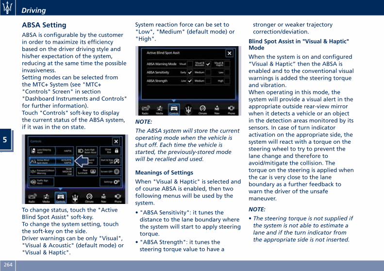
ABSA SettingABSA is configurable by the customerin order to maximize its efficiencybased on the driver driving style andhis/her expectation of the system,reducing at the same time the possibleinvasiveness.Setting modes can be selected fromthe MTC+ System (see "MTC+"Controls" Screen" in section"Dashboard Instruments and Controls"for further information).Touch "Controls" soft-key to displaythe current status of the ABSA system,if it was in the on state.
To change status, touch the "ActiveBlind Spot Assist" soft-key.To change the system setting, touchthe soft-key on the side.Driver warnings can be only "Visual","Visual & Acoustic" (default mode) or"Visual & Haptic".
System reaction force can be set to"Low", "Medium" (default mode) or"High".
NOTE:
The ABSA system will store the currentoperating mode when the vehicle isshut off. Each time the vehicle isstarted, the previously-stored modewill be recalled and used.
Meanings of Settings
When "Visual & Haptic" is selected andof course ABSA is enabled, then twofollowing menus will be used by thesystem.
• "ABSA Sensitivity": it tunes thedistance to the lane boundary wherethe system will start to apply steeringtorque.
• "ABSA Strength": it tunes thesteering torque value to have a
stronger or weaker trajectorycorrection/deviation.
Blind Spot Assist in "Visual & Haptic"Mode
When the system is on and configured“Visual & Haptic” then the ABSA isenabled and to the conventional visualwarnings is added the steering torqueand vibration.When operating in this mode, thesystem will provide a visual alert in theappropriate outside rear-view mirrorwhen it detects a vehicle or an objectin the detection areas monitored by itssensors. In case of turn indicatoractivation on the appropriate side, thesystem will react with a torque on thesteering wheel to try to prevent thelane change and therefore toavoid/mitigate the collision. Thetorque on the steering is applied whenthe car is very close to the laneboundary as a further feedback towarn the driver of the unsafemaneuver.
NOTE:
• The steering torque is not supplied ifthe system is not able to estimate alane and if the turn indicator fromthe appropriate side is not inserted.
Driving
5
264
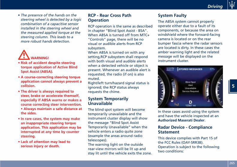
• The presence of the hands on thesteering wheel is detected by a logiccombination of a capacitive sensorinstalled in the steering wheel andthe measured applied torque at thesteering column. This leads to amore robust hands detection.
WARNING!• Risk of accident despite steeringtorque application of Active BlindSpot Assist (ABSA).
• A course-correcting steering torqueapplication cannot always prevent acollision.
• The driver is always required tosteer, brake or accelerate themself,especially if ABSA warns or makes acourse correcting steer intervention.• Always maintain a safe distance atthe sides.
• In rare cases, the system may makean inappropriate steering torqueapplication. This application may beinterrupted at any time by countersteering.
• Lack of attention may lead toserious injury or death.
RCP - Rear Cross PathOperationRCP operation is the same as describedin chapter "Blind Spot Assist - BSA".When ABSA is turned off from MTC+"Controls" page, there will be novisual or audible alerts from RCPsubsystem.When ABSA is turned on with anysetting,RCP subsystem shall respondwith both visual and audible alertswhen a detected vehicle or object ispresent. Whenever an audible alert isrequested, the radio (if on) is alsomuted.Right/left turn/hazard signal status isignored; the RCP status alwaysrequests the chime.
System TemporarilyUnavailableThe blind spot system will becometemporarily unavailable and theinstrument cluster display will showthe message “Blind Spot AssistTemporarily Unavailable” when thevehicle enters a radio quite zone(example the areas around radiotelescopes).The warning light on the outsiderear-view mirrors will be lit up andstay lit until the vehicle exits the zone.
System FaultyThe ABSA system cannot properlyoperate either due to a fault of itscomponents, or because the area onwindshield where the forward-facingcamera is located or on the rearbumper fascia where the radar sensorsare located is dirty. In these cases theamber warning light and the relatedmessage will be displayed on theinstrument cluster.
In these cases avoid using the systemand have the vehicle inspected at anAuthorized Maserati Dealer.
Radar Device - ComplianceStatementThis device complies with Part 15 ofthe FCC Rules (OAY-SRR3B).Operation is subject to the followingtwo conditions:
Driving
5
265
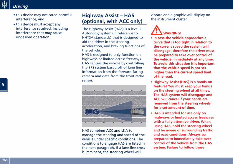
• this device may not cause harmfulinterference, and
• this device must accept anyinterference received, includinginterference that may causeundesired operation.
Highway Assist – HAS(optional, with ACC only)The Highway Assist (HAS) is a level 2Autonomy system (in reference toNHTSA standards) that is designed toaid the driver in the steering,acceleration, and braking functions ofthe vehicle.HAS is designed to only function onhighways or limited access freeways.HAS centers the vehicle by controllingthe EPS system based off of lane lineinformation from the forward-facingcamera and data from the front radarsensor.
HAS combines ACC and LKA tomanage the steering and speed of thevehicle under specific conditions. Theconditions to engage HAS are listed inthe next paragraph. If a lane line crossis imminent, the steering wheel will
vibrate and a graphic will display onthe instrument cluster.
WARNING!• In case the vehicle approaches acurve that is too tight in relation tothe current speed the system willdisengage, therefore the driver mustbe prepared to take over control ofthe vehicle immediately at any time.To avoid this situation it is importantthat the vehicle speed is not sethigher than the current speed limitof the road.
• Highway Assist (HAS) is a hands-onfeature! You must keep your handson the steering wheel at all times.The HAS system will disengage andACC will cancel if your hands areremoved from the steering wheelsfor a set amount of time.
• HAS is intended for use only onhighways or limited access freewayswith a fully attentive driver. Whenusing HAS, hold the steering wheeland be aware of surrounding trafficand road conditions. Always beprepared to immediately take overcontrol of the vehicle from the HASsystem. Failure to follow these
Driving
5
266
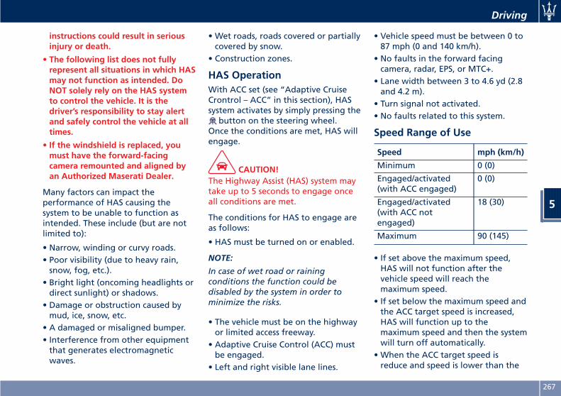
instructions could result in seriousinjury or death.
• The following list does not fullyrepresent all situations in which HASmay not function as intended. DoNOT solely rely on the HAS systemto control the vehicle. It is thedriver’s responsibility to stay alertand safely control the vehicle at alltimes.
• If the windshield is replaced, youmust have the forward-facingcamera remounted and aligned byan Authorized Maserati Dealer.
Many factors can impact theperformance of HAS causing thesystem to be unable to function asintended. These include (but are notlimited to):
• Narrow, winding or curvy roads.• Poor visibility (due to heavy rain,snow, fog, etc.).
• Bright light (oncoming headlights ordirect sunlight) or shadows.
• Damage or obstruction caused bymud, ice, snow, etc.
• A damaged or misaligned bumper.• Interference from other equipmentthat generates electromagneticwaves.
• Wet roads, roads covered or partiallycovered by snow.
• Construction zones.
HAS OperationWith ACC set (see “Adaptive CruiseCrontrol – ACC” in this section), HASsystem activates by simply pressing the
button on the steering wheel.Once the conditions are met, HAS willengage.
CAUTION!The Highway Assist (HAS) system maytake up to 5 seconds to engage onceall conditions are met.
The conditions for HAS to engage areas follows:
• HAS must be turned on or enabled.
NOTE:
In case of wet road or rainingconditions the function could bedisabled by the system in order tominimize the risks.
• The vehicle must be on the highwayor limited access freeway.
• Adaptive Cruise Control (ACC) mustbe engaged.
• Left and right visible lane lines.
• Vehicle speed must be between 0 to87 mph (0 and 140 km/h).
• No faults in the forward facingcamera, radar, EPS, or MTC+.
• Lane width between 3 to 4.6 yd (2.8and 4.2 m).
• Turn signal not activated.• No faults related to this system.
Speed Range of Use
Speed mph (km/h)
Minimum 0 (0)
Engaged/activated(with ACC engaged)
0 (0)
Engaged/activated(with ACC notengaged)
18 (30)
Maximum 90 (145)
• If set above the maximum speed,HAS will not function after thevehicle speed will reach themaximum speed.
• If set below the maximum speed andthe ACC target speed is increased,HAS will function up to themaximum speed and then the systemwill turn off automatically.
• When the ACC target speed isreduce and speed is lower than the
Driving
5
267
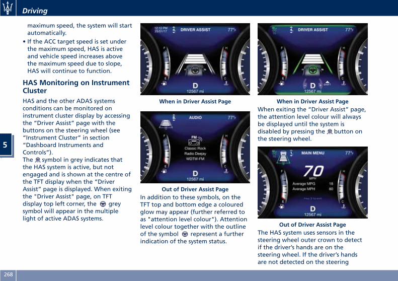
maximum speed, the system will startautomatically.
• If the ACC target speed is set underthe maximum speed, HAS is activeand vehicle speed increases abovethe maximum speed due to slope,HAS will continue to function.
HAS Monitoring on InstrumentClusterHAS and the other ADAS systemsconditions can be monitored oninstrument cluster display by accessingthe “Driver Assist” page with thebuttons on the steering wheel (see“Instrument Cluster” in section“Dashboard Instruments andControls”).The symbol in grey indicates thatthe HAS system is active, but notengaged and is shown at the centre ofthe TFT display when the “DriverAssist” page is displayed. When exitingthe "Driver Assist" page, on TFTdisplay top left corner, the greysymbol will appear in the multiplelight of active ADAS systems.
In addition to these symbols, on theTFT top and bottom edge a colouredglow may appear (further referred toas "attention level colour"). Attentionlevel colour together with the outlineof the symbol represent a furtherindication of the system status.
When exiting the “Driver Assist” page,the attention level colour will alwaysbe displayed until the system isdisabled by pressing the button onthe steering wheel.
The HAS system uses sensors in thesteering wheel outer crown to detectif the driver’s hands are on thesteering wheel. If the driver’s handsare not detected on the steering
When in Driver Assist Page
Out of Driver Assist Page
When in Driver Assist Page
Out of Driver Assist Page
Driving
5
268
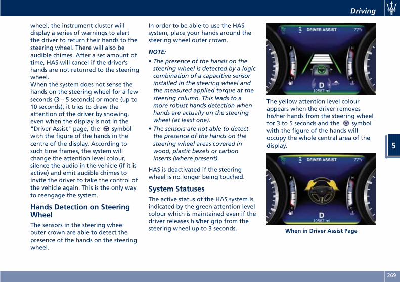
wheel, the instrument cluster willdisplay a series of warnings to alertthe driver to return their hands to thesteering wheel. There will also beaudible chimes. After a set amount oftime, HAS will cancel if the driver’shands are not returned to the steeringwheel.When the system does not sense thehands on the steering wheel for a fewseconds (3 – 5 seconds) or more (up to10 seconds), it tries to draw theattention of the driver by showing,even when the display is not in the"Driver Assist" page, the symbolwith the figure of the hands in thecentre of the display. According tosuch time frames, the system willchange the attention level colour,silence the audio in the vehicle (if it isactive) and emit audible chimes toinvite the driver to take the control ofthe vehicle again. This is the only wayto reengage the system.
Hands Detection on SteeringWheelThe sensors in the steering wheelouter crown are able to detect thepresence of the hands on the steeringwheel.
In order to be able to use the HASsystem, place your hands around thesteering wheel outer crown.
NOTE:
• The presence of the hands on thesteering wheel is detected by a logiccombination of a capacitive sensorinstalled in the steering wheel andthe measured applied torque at thesteering column. This leads to amore robust hands detection whenhands are actually on the steeringwheel (at least one).
• The sensors are not able to detectthe presence of the hands on thesteering wheel areas covered inwood, plastic bezels or carboninserts (where present).
HAS is deactivated if the steeringwheel is no longer being touched.
System StatusesThe active status of the HAS system isindicated by the green attention levelcolour which is maintained even if thedriver releases his/her grip from thesteering wheel up to 3 seconds.
The yellow attention level colourappears when the driver removeshis/her hands from the steering wheelfor 3 to 5 seconds and the symbolwith the figure of the hands willoccupy the whole central area of thedisplay.
When in Driver Assist Page
Driving
5
269
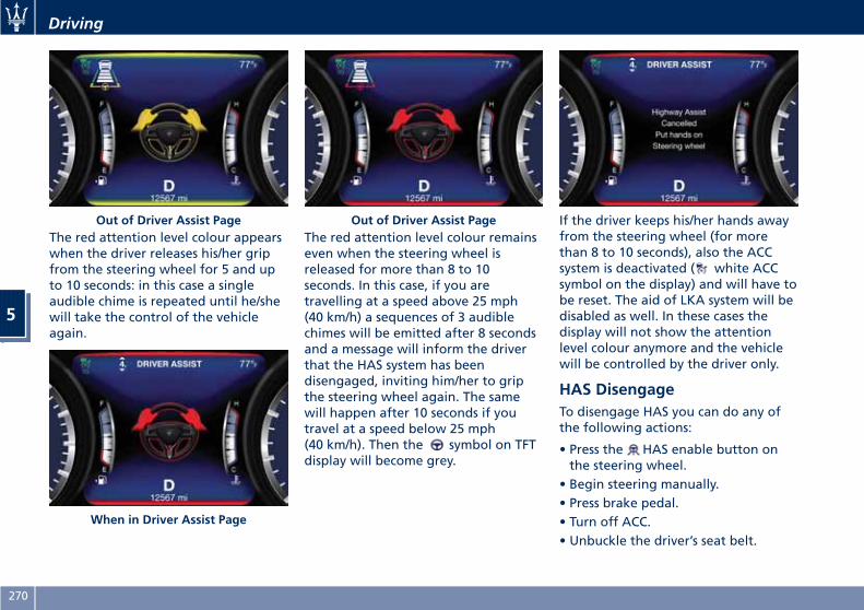
The red attention level colour appearswhen the driver releases his/her gripfrom the steering wheel for 5 and upto 10 seconds: in this case a singleaudible chime is repeated until he/shewill take the control of the vehicleagain.
The red attention level colour remainseven when the steering wheel isreleased for more than 8 to 10seconds. In this case, if you aretravelling at a speed above 25 mph(40 km/h) a sequences of 3 audiblechimes will be emitted after 8 secondsand a message will inform the driverthat the HAS system has beendisengaged, inviting him/her to gripthe steering wheel again. The samewill happen after 10 seconds if youtravel at a speed below 25 mph(40 km/h). Then the symbol on TFTdisplay will become grey.
If the driver keeps his/her hands awayfrom the steering wheel (for morethan 8 to 10 seconds), also the ACCsystem is deactivated ( white ACCsymbol on the display) and will have tobe reset. The aid of LKA system will bedisabled as well. In these cases thedisplay will not show the attentionlevel colour anymore and the vehiclewill be controlled by the driver only.
HAS DisengageTo disengage HAS you can do any ofthe following actions:
• Press the HAS enable button onthe steering wheel.
• Begin steering manually.• Press brake pedal.• Turn off ACC.• Unbuckle the driver’s seat belt.
Out of Driver Assist Page
When in Driver Assist Page
Out of Driver Assist Page
Driving
5
270
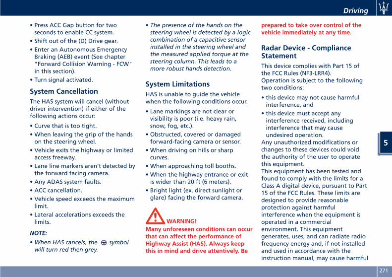
• Press ACC Gap button for twoseconds to enable CC system.
• Shift out of the (D) Drive gear.• Enter an Autonomous EmergencyBraking (AEB) event (See chapter"Forward Collision Warning - FCW"in this section).
• Turn signal activated.
System CancellationThe HAS system will cancel (withoutdriver intervention) if either of thefollowing actions occur:
• Curve that is too tight.• When leaving the grip of the handson the steering wheel.
• Vehicle exits the highway or limitedaccess freeway.
• Lane line markers aren’t detected bythe forward facing camera.
• Any ADAS system faults.• ACC cancellation.• Vehicle speed exceeds the maximumlimit.
• Lateral accelerations exceeds thelimits.
NOTE:
•When HAS cancels, the symbolwill turn red then grey.
• The presence of the hands on thesteering wheel is detected by a logiccombination of a capacitive sensorinstalled in the steering wheel andthe measured applied torque at thesteering column. This leads to amore robust hands detection.
System LimitationsHAS is unable to guide the vehiclewhen the following conditions occur.
• Lane markings are not clear orvisibility is poor (i.e. heavy rain,snow, fog, etc.).
• Obstructed, covered or damagedforward-facing camera or sensor.
• When driving on hills or sharpcurves.
• When approaching toll booths.• When the highway entrance or exitis wider than 20 ft (6 meters).
• Bright light (ex. direct sunlight orglare) facing the forward camera.
WARNING!Many unforeseen conditions can occurthat can affect the performance ofHighway Assist (HAS). Always keepthis in mind and drive attentively. Be
prepared to take over control of thevehicle immediately at any time.
Radar Device - ComplianceStatementThis device complies with Part 15 ofthe FCC Rules (NF3-LRR4).Operation is subject to the followingtwo conditions:
• this device may not cause harmfulinterference, and
• this device must accept anyinterference received, includinginterference that may causeundesired operation.
Any unauthorized modifications orchanges to these devices could voidthe authority of the user to operatethis equipment.This equipment has been tested andfound to comply with the limits for aClass A digital device, pursuant to Part15 of the FCC Rules. These limits aredesigned to provide reasonableprotection against harmfulinterference when the equipment isoperated in a commercialenvironment. This equipmentgenerates, uses, and can radiate radiofrequency energy and, if not installedand used in accordance with theinstruction manual, may cause harmful
Driving
5
271
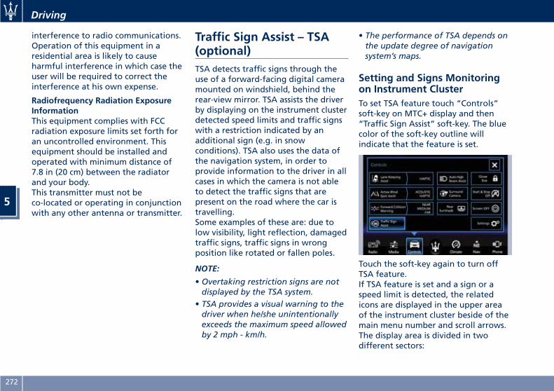
interference to radio communications.Operation of this equipment in aresidential area is likely to causeharmful interference in which case theuser will be required to correct theinterference at his own expense.
Radiofrequency Radiation ExposureInformationThis equipment complies with FCCradiation exposure limits set forth foran uncontrolled environment. Thisequipment should be installed andoperated with minimum distance of7.8 in (20 cm) between the radiatorand your body.This transmitter must not beco-located or operating in conjunctionwith any other antenna or transmitter.
Traffic Sign Assist – TSA(optional)TSA detects traffic signs through theuse of a forward-facing digital cameramounted on windshield, behind therear-view mirror. TSA assists the driverby displaying on the instrument clusterdetected speed limits and traffic signswith a restriction indicated by anadditional sign (e.g. in snowconditions). TSA also uses the data ofthe navigation system, in order toprovide information to the driver in allcases in which the camera is not ableto detect the traffic signs that arepresent on the road where the car istravelling.Some examples of these are: due tolow visibility, light reflection, damagedtraffic signs, traffic signs in wrongposition like rotated or fallen poles.
NOTE:
• Overtaking restriction signs are notdisplayed by the TSA system.
• TSA provides a visual warning to thedriver when he/she unintentionallyexceeds the maximum speed allowedby 2 mph - km/h.
• The performance of TSA depends onthe update degree of navigationsystem’s maps.
Setting and Signs Monitoringon Instrument ClusterTo set TSA feature touch “Controls”soft-key on MTC+ display and then“Traffic Sign Assist” soft-key. The bluecolor of the soft-key outline willindicate that the feature is set.
Touch the soft-key again to turn offTSA feature.If TSA feature is set and a sign or aspeed limit is detected, the relatedicons are displayed in the upper areaof the instrument cluster beside of themain menu number and scroll arrows.The display area is divided in twodifferent sectors:
Driving
5
272
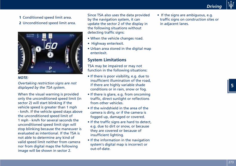
1 Conditioned speed limit area.
2 Unconditioned speed limit area.
NOTE:
Overtaking restriction signs are notdisplayed by the TSA system.
When the visual warning is providedonly the unconditioned speed limit (insector 2) will start blinking if thevehicle speed is greater than 1 mph- km/h. If the vehicle speed stays abovethe unconditioned speed limit of1 mph - km/h for several seconds theunconditioned speed limit sign willstop blinking because the maneuver isevaluated as intentional. If the TSA isnot able to determine any kind ofvalid speed limit neither from cameranor from digital maps the followingimage will be shown in sector 2.
Since TSA also uses the data providedby the navigation system, it canupdate the sector 2 of the display inthe following situations withoutdetecting traffic signs:
• When the vehicle changes road.• Highway enter/exit.• Urban area stored in the digital mapenter/exit.
System LimitationsTSA may be impaired or may notfunction in the following situations:
• If there is poor visibility, e.g. due toinsufficient illumination of the road,if there are highly variable shadeconditions or in rain, snow or fog.
• If there is glare, e.g. from oncomingtraffic, direct sunlight or reflectionsfrom other vehicles.
• If the windshield in the area of thecamera is dirty, or if the camera isfogged up, damaged or covered.
• If the traffic signs are hard to detect,e.g. due to dirt or snow, or becausethey are covered or because ofinsufficient lighting.
• If the information in the navigationsystem's digital map is incorrect orout-of-date.
• If the signs are ambiguous, e.g.traffic signs on construction sites orin adjacent lanes.
Driving
5
273
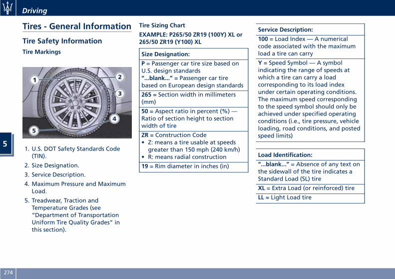
Tires - General Information
Tire Safety InformationTire Markings
1. U.S. DOT Safety Standards Code(TIN).
2. Size Designation.
3. Service Description.
4. Maximum Pressure and MaximumLoad.
5. Treadwear, Traction andTemperature Grades (see“Department of TransportationUniform Tire Quality Grades” inthis section).
Tire Sizing Chart
EXAMPLE: P265/50 ZR19 (100Y) XL or265/50 ZR19 (Y100) XL
Size Designation:
P = Passenger car tire size based onU.S. design standards“...blank...” = Passenger car tirebased on European design standards
265 = Section width in millimeters(mm)
50 = Aspect ratio in percent (%) —Ratio of section height to sectionwidth of tire
ZR = Construction Code• Z: means a tire usable at speedsgreater than 150 mph (240 km/h)
• R: means radial construction
19 = Rim diameter in inches (in)
Service Description:
100 = Load Index — A numericalcode associated with the maximumload a tire can carry
Y = Speed Symbol — A symbolindicating the range of speeds atwhich a tire can carry a loadcorresponding to its load indexunder certain operating conditions.The maximum speed correspondingto the speed symbol should only beachieved under specified operatingconditions (i.e., tire pressure, vehicleloading, road conditions, and postedspeed limits)
Load Identification:
“...blank...” = Absence of any text onthe sidewall of the tire indicates aStandard Load (SL) tire
XL = Extra Load (or reinforced) tire
LL = Light Load tire
Driving
5
274
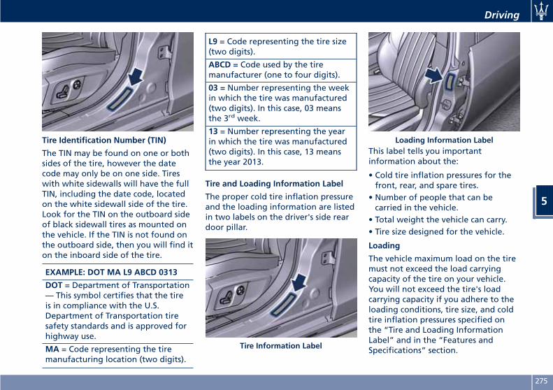
Tire Identification Number (TIN)
The TIN may be found on one or bothsides of the tire, however the datecode may only be on one side. Tireswith white sidewalls will have the fullTIN, including the date code, locatedon the white sidewall side of the tire.Look for the TIN on the outboard sideof black sidewall tires as mounted onthe vehicle. If the TIN is not found onthe outboard side, then you will find iton the inboard side of the tire.
EXAMPLE: DOT MA L9 ABCD 0313
DOT = Department of Transportation— This symbol certifies that the tireis in compliance with the U.S.Department of Transportation tiresafety standards and is approved forhighway use.
MA = Code representing the tiremanufacturing location (two digits).
L9 = Code representing the tire size(two digits).
ABCD = Code used by the tiremanufacturer (one to four digits).
03 = Number representing the weekin which the tire was manufactured(two digits). In this case, 03 meansthe 3rd week.
13 = Number representing the yearin which the tire was manufactured(two digits). In this case, 13 meansthe year 2013.
Tire and Loading Information Label
The proper cold tire inflation pressureand the loading information are listedin two labels on the driver's side reardoor pillar.
This label tells you importantinformation about the:
• Cold tire inflation pressures for thefront, rear, and spare tires.
• Number of people that can becarried in the vehicle.
• Total weight the vehicle can carry.• Tire size designed for the vehicle.
Loading
The vehicle maximum load on the tiremust not exceed the load carryingcapacity of the tire on your vehicle.You will not exceed the tire's loadcarrying capacity if you adhere to theloading conditions, tire size, and coldtire inflation pressures specified onthe “Tire and Loading InformationLabel” and in the “Features andSpecifications” section.Tire Information Label
Loading Information Label
Driving
5
275
NOTE:
Under a maximum loaded vehiclecondition, gross axle weight ratings(GAWRs) for the front and rear axlesmust not be exceeded.
TiresDriving over rough or damaged roadsurfaces, as well as debris, curbs andother obstacles can cause seriousdamage to wheels, tires, andsuspension parts.This is more likely to occur withlow-profile tires, which provide lesscushioning between the wheel and theroad.Be careful to avoid road hazards andreduce your speed, especially if yourvehicle is equipped with low profiletires.
WARNING!Overloading of your tires isdangerous. Overloading can cause tirefailure, affect vehicle handling, andincrease the stopping distance. Usetires of the recommended loadcapacity for your vehicle. Neveroverload them.
Department of TransportationUniform Tire Quality GradesThe following tire grading categorieswere established by the NationalHighway Traffic Safety Administration.The specific grade rating assigned bythe tire's manufacturer in eachcategory is shown on the sidewall ofthe tires on your vehicle.All passenger car tires must conform toFederal safety requirements inaddition to these grades.
Treadwear
The Treadwear grade is a comparativerating, based on the wear rate of thetire when tested under controlledconditions on a specified governmenttest course. For example, a tire graded150 would wear one and one-halftimes as well on the governmentcourse as a tire graded 100. Therelative performance of tires dependsupon the actual conditions of theiruse, however, and may departsignificantly from the norm due tovariations in driving habits, servicepractices, and differences in roadcharacteristics and climate.
Traction Grades
The Traction grades, from highest tolowest, are AAA, A, B, and C. These
grades represent the tire's ability tostop on wet pavement, as measuredunder controlled conditions onspecified government test surfaces ofasphalt and concrete. A tire marked Cmay have poor traction performance.
WARNING!The traction grade assigned to this tireis based on straight-ahead brakingtraction tests, and does not includeacceleration, cornering, hydroplaning,or peak traction characteristics.
Temperature Grades
The temperature grades are A (thehighest), B, and C, representing thetire's resistance to the generation ofheat and its ability to dissipate heat,when tested under controlledconditions on a specified indoorlaboratory test wheel. Sustained hightemperature can cause the material ofthe tire to degenerate and reduce tirelife, and excessive temperature canlead to sudden tire failure. The gradeC corresponds to a level ofperformance, which all passenger cartires must meet under the FederalMotor Vehicle Safety Standard No.109. Grades B and A represent higher
Driving
5
276
levels of performance on thelaboratory test wheel, than theminimum required by law.
WARNING!The temperature grade for this tire isestablished for a tire that is properlyinflated and not overloaded.Excessive speed, under-inflation, orexcessive loading, either separately orin combination, can cause heatbuildup and possible tire failure.
Tire PressureProper tire inflation pressure isessential for safety and bestperformance of your vehicle. The tirepressure monitoring system “TPMS”setup on the vehicle (see “TirePressure Monitoring System” in thissection) may alert the driver aboutinsufficient tire pressure even thoughthe driver is responsible for regularlychecking the tire pressure.Radial tires fitted on the vehicle maylook properly inflated even when theyactually are under inflated. Do notmake a visual judgment whendetermining proper inflation.Three primary driving aspects areaffected by improper tire pressure:
Safety
WARNING!• Improperly inflated tires can bedangerous.
• Under-inflation increases tire flexingand can result in tire overheating.
• Over-inflation reduces a tire's abilityto cushion shock. Objects on theroad and potholes can causedamage that results in tire failure.
• Over-inflated or under-inflated tirescan affect vehicle handling and canfail suddenly, resulting in loss ofvehicle control.
• Unequal tire pressures can causesteering problems.
• Unequal tire pressures from one sideof the vehicle to the other can causethe vehicle to drift to the right orleft.
• Always drive with each tire inflatedto the recommended cold tireinflation pressure.
EconomyImproper inflation pressures maycause uneven wear patterns todevelop across the tire tread. Theseabnormal wear patterns will reduce
tread life resulting in a need forearlier tire replacement. Under-inflation also increases tire rollingresistance resulting in higher fuelconsumption.
Ride comfort and vehicle stabilityProper tire inflation contributes to acomfortable ride. Over-inflationproduces a jarring and uncomfortableride.
Tire Pressure CheckupThe proper cold tire inflation pressureis indicated on the driver's side reardoor pillar and on the table “TireInflation Pressure” in section“Features and Specifications”.Inflation pressure specified on thetable always refers to “cold tireinflation pressure”. Cold tire inflationpressure is defined as the tire pressureafter the vehicle has not been drivenfor at least three hours, or driven lessthan 1 mi (1.6 km) after a three hourperiod.Check tire pressures more often incase of significant outsidetemperature changes, as tire pressurevaries according to temperaturechanges.The pressure should be checked and ifnecessary adjusted; tire wear and
Driving
5
277
overall conditions should also bechecked monthly. Tire pressureschange by approximately 1 PSI (0.07bar) per 12°F (7°C) of air temperaturechange. Keep this in mind whenchecking tire pressure inside a garage,especially in winter.Example: If garage temperature = 68°F(20°C) and the outside temperature =32°F (0°C) then the cold tire inflationpressure should be increased by 3 PSI(0.21 bar) for every 12°F (7°C) for thisoutside temperature condition.Tire pressure may increase from 2 to 6PSI (0.13 to 0.4 bar) during operation.DO NOT reduce this normal pressurebuild-up or your tire pressure will betoo low. After inspecting or adjustingthe tire pressure, always reinstall thevalve stem cap. This will preventmoisture and dirt from entering thevalve stem, which could damage thevalve stem and the TPMS sensorconnected to it.
Tread Wear IndicatorsTread wear indicators are in theoriginal equipment tires to help youdetermine when your tires should bereplaced.These indicators are molded into thebottom of the tread grooves.
When the tread is worn to one of thetread wear indicators, the tire shouldbe replaced.
WARNING!The wet performance (aquaplaningresistance) will decreaseproportionally to the thickness of thetread.
Tires DurabilityThe service life of a tire depends onvarious factors including, but notlimited to:
• driving style;• tire pressure;• distance driven.
WARNING!Tires and the spare tire (if equipped)should be replaced after six years,regardless of the remaining tread.Failure to follow this warning couldresult in tire failure.
Replacement Tires
NOTE:
In order to maintain high performanceand safety level under all drivingconditions, Maserati stronglyrecommends to use tires equivalent tothe originals in size, quality andperformance when replacement isneeded.
For the size designation of your tiresee the label on the driver's side reardoor pillar or see table “Wheels” insection “Features and Specifications”.The “Load Index” and “Speed Symbol”for your tire will be found on theoriginal equipment tire sidewall.
NOTE:
Maserati recommends Maserati GenuineTires marked with “MGT” logospecifically designed for its models.
It is recommended to replace the twofront tires or two rear tires as a pair.Replacing just one tire can seriouslyaffect your vehicle’s handling.If you ever replace a wheel assembly,make sure that the wheel’sspecifications (valve, TPMS sensor andtire) match those of the originalwheels. Failure to use equivalentreplacement tires may adversely affect
Driving
5
278
the safety, handling, and ride of yourvehicle.Your Authorized Maserati Dealer isavailable to provide suggestions as tothe types of tires most suited to theuse foreseen by the Customer.
WARNING!• Do not use a tire, wheel size orrating other than that specified foryour vehicle. Some combinations ofunapproved tires and wheels maychange suspension dimensions andperformance characteristics,resulting in altered steering,handling, and braking operations ofthe vehicle. This can causeunpredictable handling and stress tosteering and suspensioncomponents. Use only the tire andwheel sizes with load ratingsappointed for your vehicle.
• Never use a tire with a smaller loadindex or capacity, other than whatwas originally equipped on yourvehicle. Using a tire with a smallerload index could result in tireoverloading and failure.
• Always check the maximum speedrating on the tire sidewall on anytire on the vehicle.
• Never exceed the maximum speedrating of the tires. Risk of accidentand serious personal injury due toexcessive speed.
• Failure to equip your vehicle withtires having adequate speedcapability can result in tire failure.
CAUTION!Replacing original tires with tires of adifferent size may result in falsespeedometer and odometer readings.
Winter TiresThese tires are specially designed fordriving on snow and ice and are fittedto replace the ones supplied with thevehicle. Winter or all-season tires canbe identified by the M+S (Mud &Snow) or 3PMSF (3 Peaks MountainSnow Flake) designation on the tiresidewall.Before mounting winter tires, contactan Authorized Maserati Dealer toreceive the technical informationnecessary to advise you on wheel andtire compatibility.As to the type of tires to use, inflationpressures and winter tiresspecifications, carefully follow theindications as reported in the
“Technical Data” and “Tire InflationPressure” chapters in section “Featuresand Specifications”.
WARNING!The standard tires profile and rubbermixture are optimized for wet and drydriving conditions. Standard tires maynot prove favorable for snowconditions.
NOTE:
Snow tires should have the same loadcapacity as original equipment tiresand should be mounted on all fourwheels.
Snow ChainsMaserati approved traction devices (orsnow chains) may be used to improvetraction on compacted snow in heavysnow conditions.The use of snow chains is specified bylocal regulations of each country.Use snow chains of reduceddimensions, with a maximumprojection of 0.23 in (6 mm) beyondthe tire tread.The chains may be fitted only on 18”and 19” rear wheel tires.
Driving
5
279
Please contact an Authorized MaseratiDealer for further information.Check the snow chain tension afterdriving for a distance of about 55 yd(50 m) with the chains fitted.With the snow chains fitted, it isadvisable to deactivate the ESC system(see chapter “Drive Mode” in thissection).
CAUTION!
• The use of non-recommended snowchains may damage the vehicle.
• Broken snow chains can cause seriousdamage. Stop the vehicleimmediately if noise occurs thatcould indicate snow chain breakage.Remove the damaged parts of thesnow chain before further use.
• Do not exceed 30 mph (50 km/h).• Drive cautiously and avoid severeturns and large bumps, especiallywith a loaded vehicle.
• Avoid holes in the road, do not driveover steps or sidewalks and do notdrive on long stretches withoutsnow. This will prevent damage tothe vehicle and the roadbed.
NOTE:
The Authorized Maserati Dealer canprovide you with all information aboutthe Maserati Snow Chains, available inthe "Genuine Accessories" range.
Compact Spare TireThe limited-use spare tire, or compactspare tire, is for temporary emergencyuse only.This tire is identified by a label indicatingthe driving speed limitations to complywith when using the spare tire.Inflate the spare tire to the coldinflation pressure listed on the table“Tire Inflation Pressure” in section“Features and Specifications”.Mounting the spare tire affects vehiclehandling. Replace (or repair) as soon aspossible the original equipment tireand reinstall it on the vehicle. Do notinstall more than one compact sparetire and wheel on the vehicle at atime.
WARNING!With these compact spare tires, do notdrive more than 50 mph (80 km/h).Temporary use spares have limitedtread life.
Tire Pressure MonitoringSystem (TPMS)The Tire Pressure Monitoring System(TPMS) will warn the driver of a lowtire pressure according to the vehiclerecommended cold pressure indicatedon the table “Tire Inflation Pressure”in section “Features andSpecifications” and on the labelapplied on the driver's side rear doorpillar.Tire pressure should always be setbased on cold inflation tire pressure.The cold tire inflation pressure mustnot exceed the maximum inflationpressure molded into the tire sidewall.Check “Tires – General Information” insection “Driving” for information onhow to properly inflate the tires.The tire pressure will also increase asthe vehicle is driven - this is normaland there is no adjustment requiredwhen this occurs.The TPMS will warn the driver of a lowtire pressure if the tire pressure fallsbelow the low-pressure warning limitfor any reason, including lowtemperature effects and naturalpressure loss of the tire.The TPMS will continue to warn thedriver of low tire pressure as long asthe condition persists and will not turn
Driving
5
280
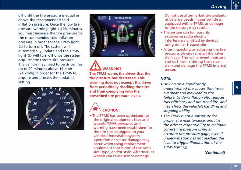
off until the tire pressure is equal orabove the recommended coldinflation pressure. Once the low tirepressure warning light illuminates,you must increase the tire pressure tothe recommended cold inflationpressure in order for the TPMS light
to turn off. The system willautomatically update and the TPMSlight will turn off once the systemacquires the correct tire pressure.The vehicle may need to be driven forup to 20 minutes above 15 mph(24 km/h) in order for the TPMS toacquire and process the updatedsetting.
WARNING!The TPMS warns the driver that thetire pressure has decreased. Thiswarning does not exempt the driverfrom periodically checking the tiresand from complying with theprescribed tire pressure levels.
CAUTION!• The TPMS has been optimized forthe original equipment tires andwheels. TPMS pressures andwarning have been established forthe tire size equipped on yourvehicle. Undesirable systemoperation or sensor damage mayoccur when using replacementequipment that is not of the samesize, type, and/or style. Aftermarketwheels can cause sensor damage.
Do not use aftermarket tire sealantsor balance beads if your vehicle isequipped with a TPMS, as damageto the sensors may result.
• The system can temporarilyexperience radio-electricinterference emitted by devicesusing similar frequencies.
• After inspecting or adjusting the tirepressure, always reinstall the valvestem cap. This will prevent moistureand dirt from entering the valvestem and damage the TPMS internalsensor.
NOTE:
• Driving on a significantlyunderinflated tire causes the tire tooverheat and may lead to tirefailure. Under-inflation also reducesfuel efficiency and tire tread life, andmay affect the vehicle’s handling andstopping ability.
• The TPMS is not a substitute forproper tire maintenance, and it isthe driver’s responsibility to maintaincorrect tire pressure using anaccurate tire pressure gage, even ifunder-inflation has not reached thelevel to trigger illumination of theTPMS light .
(Continued)
Driving
5
281
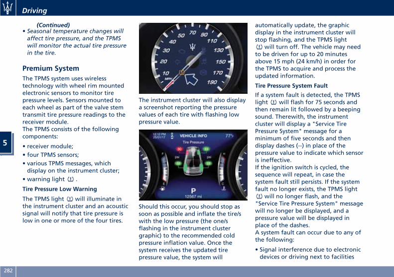
(Continued)• Seasonal temperature changes willaffect tire pressure, and the TPMSwill monitor the actual tire pressurein the tire.
Premium SystemThe TPMS system uses wirelesstechnology with wheel rim mountedelectronic sensors to monitor tirepressure levels. Sensors mounted toeach wheel as part of the valve stemtransmit tire pressure readings to thereceiver module.The TPMS consists of the followingcomponents:
• receiver module;• four TPMS sensors;• various TPMS messages, whichdisplay on the instrument cluster;
• warning light .
Tire Pressure Low Warning
The TPMS light will illuminate inthe instrument cluster and an acousticsignal will notify that tire pressure islow in one or more of the four tires.
The instrument cluster will also displaya screenshot reporting the pressurevalues of each tire with flashing lowpressure value.
Should this occur, you should stop assoon as possible and inflate the tire/swith the low pressure (the one/sflashing in the instrument clustergraphic) to the recommended coldpressure inflation value. Once thesystem receives the updated tirepressure value, the system will
automatically update, the graphicdisplay in the instrument cluster willstop flashing, and the TPMS light
will turn off. The vehicle may needto be driven for up to 20 minutesabove 15 mph (24 km/h) in order forthe TPMS to acquire and process theupdated information.
Tire Pressure System Fault
If a system fault is detected, the TPMSlight will flash for 75 seconds andthen remain lit followed by a beepingsound. Therewith, the instrumentcluster will display a "Service TirePressure System" message for aminimum of five seconds and thendisplay dashes (--) in place of thepressure value to indicate which sensoris ineffective.If the ignition switch is cycled, thesequence will repeat, in case thesystem fault still persists. If the systemfault no longer exists, the TPMS light
will no longer flash, and the"Service Tire Pressure System" messagewill no longer be displayed, and apressure value will be displayed inplace of the dashes.A system fault can occur due to any ofthe following:
• Signal interference due to electronicdevices or driving next to facilities
Driving
5
282
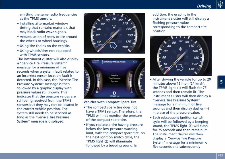
emitting the same radio frequenciesas the TPMS sensors.
• Installing aftermarket windowtinting that contains materials thatmay block radio wave signals.
• Accumulation of snow or ice aroundthe wheels or wheel housings.
• Using tire chains on the vehicle.• Using wheels/tires not equippedwith TPMS sensors.
The instrument cluster will also displaya "Service Tire Pressure System"message for a minimum of fiveseconds when a system fault related toan incorrect sensor location fault isdetected. In this case, the "Service TirePressure System" message is thenfollowed by a graphic display withpressure values still shown. Thisindicates that the pressure values arestill being received from the TPMSsensors but they may not be located inthe correct vehicle position. Thesystem still needs to be serviced aslong as the "Service Tire PressureSystem" message is displayed.
Vehicles with Compact Spare Tire
• The compact spare tire does nothave a TPMS sensor. Therefore, theTPMS will not monitor the pressureof the compact spare tire.
• If you replace a tire having pressurebelow the low-pressure warninglimit, with the compact spare tire, onthe next ignition switch cycle, theTPMS light will illuminatefollowed by a beeping sound. In
addition, the graphic in theinstrument cluster will still display aflashing pressure valuecorresponding to the compact tireposition.
• After driving the vehicle for up to 20minutes above 15 mph (24 km/h),the TPMS light will flash for 75seconds and then remain lit. Theinstrument cluster will then display a"Service Tire Pressure System"message for a minimum of fiveseconds and then display dashes (--)in place of the pressure value.
• Each subsequent ignition switchcycle will be followed by a beepingsound, the TPMS light will flashfor 75 seconds and then remain lit.The instrument cluster will thendisplay a "Service Tire PressureSystem" message for a minimum offive seconds and subsequently
Driving
5
283
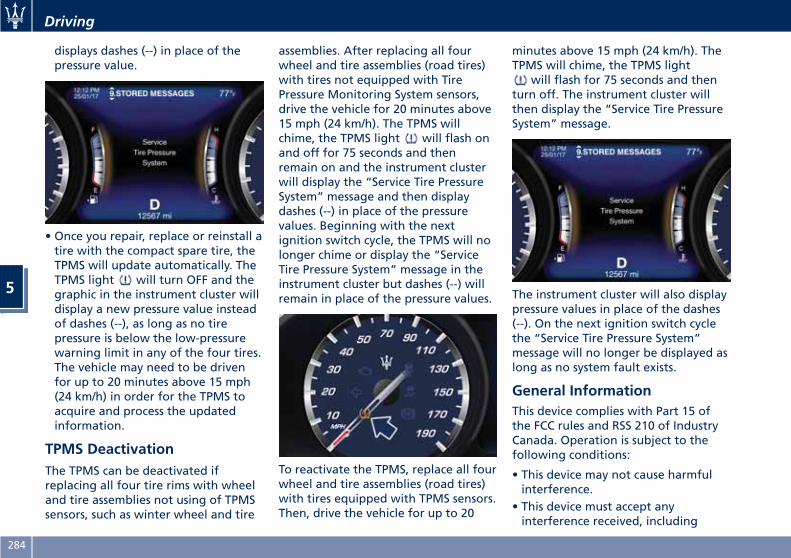
displays dashes (--) in place of thepressure value.
• Once you repair, replace or reinstall atire with the compact spare tire, theTPMS will update automatically. TheTPMS light will turn OFF and thegraphic in the instrument cluster willdisplay a new pressure value insteadof dashes (--), as long as no tirepressure is below the low-pressurewarning limit in any of the four tires.The vehicle may need to be drivenfor up to 20 minutes above 15 mph(24 km/h) in order for the TPMS toacquire and process the updatedinformation.
TPMS DeactivationThe TPMS can be deactivated ifreplacing all four tire rims with wheeland tire assemblies not using of TPMSsensors, such as winter wheel and tire
assemblies. After replacing all fourwheel and tire assemblies (road tires)with tires not equipped with TirePressure Monitoring System sensors,drive the vehicle for 20 minutes above15 mph (24 km/h). The TPMS willchime, the TPMS light will flash onand off for 75 seconds and thenremain on and the instrument clusterwill display the “Service Tire PressureSystem” message and then displaydashes (--) in place of the pressurevalues. Beginning with the nextignition switch cycle, the TPMS will nolonger chime or display the “ServiceTire Pressure System” message in theinstrument cluster but dashes (--) willremain in place of the pressure values.
To reactivate the TPMS, replace all fourwheel and tire assemblies (road tires)with tires equipped with TPMS sensors.Then, drive the vehicle for up to 20
minutes above 15 mph (24 km/h). TheTPMS will chime, the TPMS light
will flash for 75 seconds and thenturn off. The instrument cluster willthen display the “Service Tire PressureSystem” message.
The instrument cluster will also displaypressure values in place of the dashes(--). On the next ignition switch cyclethe “Service Tire Pressure System”message will no longer be displayed aslong as no system fault exists.
General InformationThis device complies with Part 15 ofthe FCC rules and RSS 210 of IndustryCanada. Operation is subject to thefollowing conditions:
• This device may not cause harmfulinterference.
• This device must accept anyinterference received, including
Driving
5
284
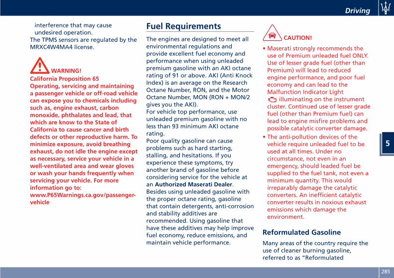
interference that may causeundesired operation.
The TPMS sensors are regulated by theMRXC4W4MA4 license.
WARNING!California Proposition 65Operating, servicing and maintaininga passenger vehicle or off-road vehiclecan expose you to chemicals includingsuch as, engine exhaust, carbonmonoxide, phthalates and lead, thatwhich are know to the State ofCalifornia to cause cancer and birthdefects or other reproductive harm. Tominimize exposure, avoid breathingexhaust, do not idle the engine exceptas necessary, service your vehicle in awell-ventilated area and wear glovesor wash your hands frequently whenservicing your vehicle. For moreinformation go to:www.P65Warnings.ca.gov/passenger-vehicle
Fuel RequirementsThe engines are designed to meet allenvironmental regulations andprovide excellent fuel economy andperformance when using unleadedpremium gasoline with an AKI octanerating of 91 or above. AKI (Anti KnockIndex) is an average on the ResearchOctane Number, RON, and the MotorOctane Number, MON (RON + MON/2gives you the AKI).For vehicle top performance, useunleaded premium gasoline with noless than 93 minimum AKI octanerating.Poor quality gasoline can causeproblems such as hard starting,stalling, and hesitations. If youexperience these symptoms, tryanother brand of gasoline beforeconsidering service for the vehicle atan Authorized Maserati Dealer.Besides using unleaded gasoline withthe proper octane rating, gasolinethat contain detergents, anti-corrosionand stability additives arerecommended. Using gasoline thathave these additives may help improvefuel economy, reduce emissions, andmaintain vehicle performance.
CAUTION!
• Maserati strongly recommends theuse of Premium unleaded fuel ONLY.Use of lesser grade fuel (other thanPremium) will lead to reducedengine performance, and poor fueleconomy and can lead to theMalfunction Indicator Light
illuminating on the instrumentcluster. Continued use of lesser gradefuel (other than Premium fuel) canlead to engine misfire problems andpossible catalytic converter damage.
• The anti-pollution devices of thevehicle require unleaded fuel to beused at all times. Under nocircumstance, not even in anemergency, should leaded fuel besupplied to the fuel tank, not even aminimum quantity. This wouldirreparably damage the catalyticconverters. An inefficient catalyticconverter results in noxious exhaustemissions which damage theenvironment.
Reformulated GasolineMany areas of the country require theuse of cleaner burning gasoline,referred to as “Reformulated
Driving
5
285
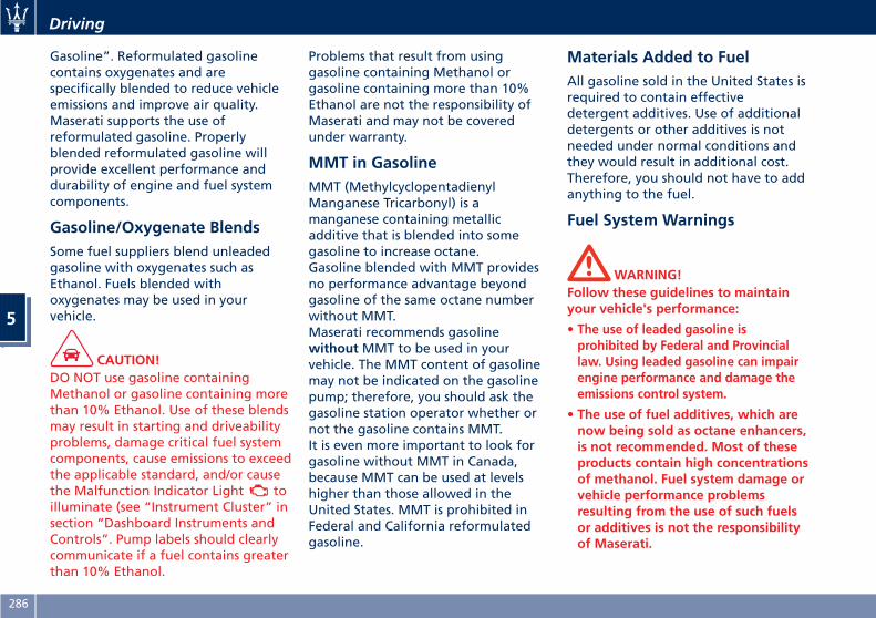
Gasoline”. Reformulated gasolinecontains oxygenates and arespecifically blended to reduce vehicleemissions and improve air quality.Maserati supports the use ofreformulated gasoline. Properlyblended reformulated gasoline willprovide excellent performance anddurability of engine and fuel systemcomponents.
Gasoline/Oxygenate BlendsSome fuel suppliers blend unleadedgasoline with oxygenates such asEthanol. Fuels blended withoxygenates may be used in yourvehicle.
CAUTION!DO NOT use gasoline containingMethanol or gasoline containing morethan 10% Ethanol. Use of these blendsmay result in starting and driveabilityproblems, damage critical fuel systemcomponents, cause emissions to exceedthe applicable standard, and/or causethe Malfunction Indicator Light toilluminate (see “Instrument Cluster” insection “Dashboard Instruments andControls”. Pump labels should clearlycommunicate if a fuel contains greaterthan 10% Ethanol.
Problems that result from usinggasoline containing Methanol orgasoline containing more than 10%Ethanol are not the responsibility ofMaserati and may not be coveredunder warranty.
MMT in GasolineMMT (MethylcyclopentadienylManganese Tricarbonyl) is amanganese containing metallicadditive that is blended into somegasoline to increase octane.Gasoline blended with MMT providesno performance advantage beyondgasoline of the same octane numberwithout MMT.Maserati recommends gasolinewithoutMMT to be used in yourvehicle. The MMT content of gasolinemay not be indicated on the gasolinepump; therefore, you should ask thegasoline station operator whether ornot the gasoline contains MMT.It is even more important to look forgasoline without MMT in Canada,because MMT can be used at levelshigher than those allowed in theUnited States. MMT is prohibited inFederal and California reformulatedgasoline.
Materials Added to FuelAll gasoline sold in the United States isrequired to contain effectivedetergent additives. Use of additionaldetergents or other additives is notneeded under normal conditions andthey would result in additional cost.Therefore, you should not have to addanything to the fuel.
Fuel System Warnings
WARNING!Follow these guidelines to maintainyour vehicle's performance:
• The use of leaded gasoline isprohibited by Federal and Provinciallaw. Using leaded gasoline can impairengine performance and damage theemissions control system.
• The use of fuel additives, which arenow being sold as octane enhancers,is not recommended. Most of theseproducts contain high concentrationsof methanol. Fuel system damage orvehicle performance problemsresulting from the use of such fuelsor additives is not the responsibilityof Maserati.
Driving
5
286
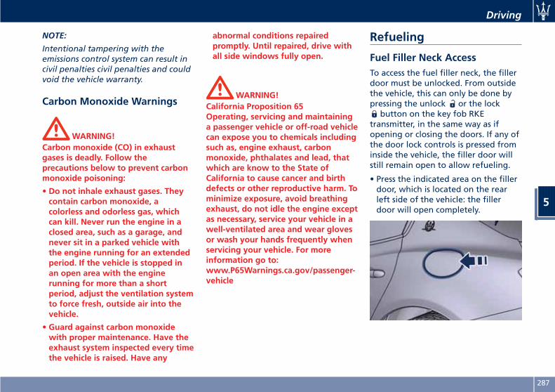
NOTE:
Intentional tampering with theemissions control system can result incivil penalties civil penalties and couldvoid the vehicle warranty.
Carbon Monoxide Warnings
WARNING!Carbon monoxide (CO) in exhaustgases is deadly. Follow theprecautions below to prevent carbonmonoxide poisoning:
• Do not inhale exhaust gases. Theycontain carbon monoxide, acolorless and odorless gas, whichcan kill. Never run the engine in aclosed area, such as a garage, andnever sit in a parked vehicle withthe engine running for an extendedperiod. If the vehicle is stopped inan open area with the enginerunning for more than a shortperiod, adjust the ventilation systemto force fresh, outside air into thevehicle.
• Guard against carbon monoxidewith proper maintenance. Have theexhaust system inspected every timethe vehicle is raised. Have any
abnormal conditions repairedpromptly. Until repaired, drive withall side windows fully open.
WARNING!California Proposition 65Operating, servicing and maintaininga passenger vehicle or off-road vehiclecan expose you to chemicals includingsuch as, engine exhaust, carbonmonoxide, phthalates and lead, thatwhich are know to the State ofCalifornia to cause cancer and birthdefects or other reproductive harm. Tominimize exposure, avoid breathingexhaust, do not idle the engine exceptas necessary, service your vehicle in awell-ventilated area and wear glovesor wash your hands frequently whenservicing your vehicle. For moreinformation go to:www.P65Warnings.ca.gov/passenger-vehicle
Refueling
Fuel Filler Neck AccessTo access the fuel filler neck, the fillerdoor must be unlocked. From outsidethe vehicle, this can only be done bypressing the unlock or the lock
button on the key fob RKEtransmitter, in the same way as ifopening or closing the doors. If any ofthe door lock controls is pressed frominside the vehicle, the filler door willstill remain open to allow refueling.
• Press the indicated area on the fillerdoor, which is located on the rearleft side of the vehicle: the fillerdoor will open completely.
Driving
5
287
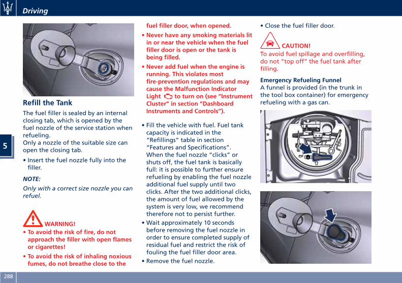
Refill the TankThe fuel filler is sealed by an internalclosing tab, which is opened by thefuel nozzle of the service station whenrefueling.Only a nozzle of the suitable size canopen the closing tab.
• Insert the fuel nozzle fully into thefiller.
NOTE:
Only with a correct size nozzle you canrefuel.
WARNING!• To avoid the risk of fire, do notapproach the filler with open flamesor cigarettes!
• To avoid the risk of inhaling noxiousfumes, do not breathe close to the
fuel filler door, when opened.
• Never have any smoking materials litin or near the vehicle when the fuelfiller door is open or the tank isbeing filled.
• Never add fuel when the engine isrunning. This violates mostfire-prevention regulations and maycause the Malfunction IndicatorLight to turn on (see “InstrumentCluster” in section “DashboardInstruments and Controls”).
• Fill the vehicle with fuel. Fuel tankcapacity is indicated in the“Refillings” table in section“Features and Specifications”.When the fuel nozzle “clicks” orshuts off, the fuel tank is basicallyfull: it is possible to further ensurerefueling by enabling the fuel nozzleadditional fuel supply until twoclicks. After the two additional clicks,the amount of fuel allowed by thesystem is very low, we recommendtherefore not to persist further.
• Wait approximately 10 secondsbefore removing the fuel nozzle inorder to ensure completed supply ofresidual fuel and restrict the risk offouling the fuel filler door area.
• Remove the fuel nozzle.
• Close the fuel filler door.
CAUTION!To avoid fuel spillage and overfilling,do not “top off” the fuel tank afterfilling.
Emergency Refueling FunnelA funnel is provided (in the trunk inthe tool box container) for emergencyrefueling with a gas can.
Driving
5
288
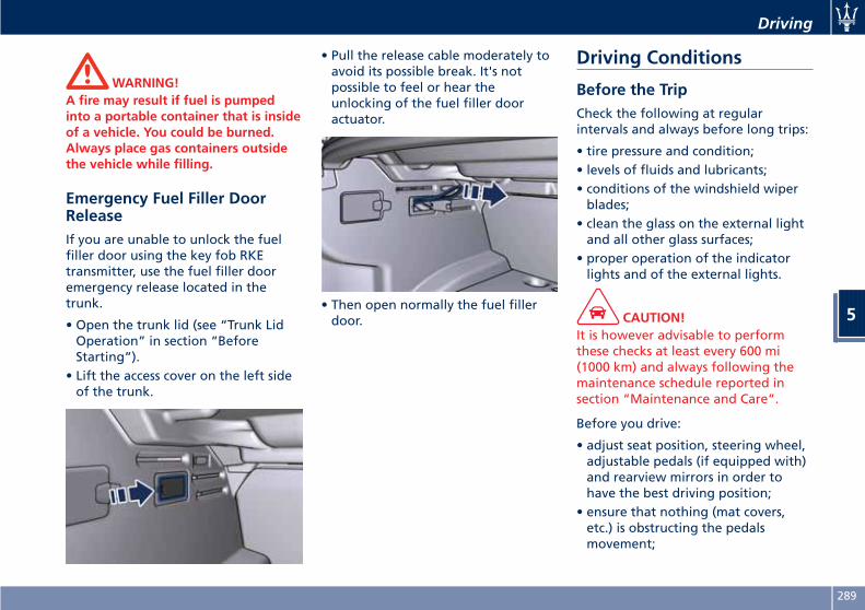
WARNING!A fire may result if fuel is pumpedinto a portable container that is insideof a vehicle. You could be burned.Always place gas containers outsidethe vehicle while filling.
Emergency Fuel Filler DoorReleaseIf you are unable to unlock the fuelfiller door using the key fob RKEtransmitter, use the fuel filler dooremergency release located in thetrunk.
• Open the trunk lid (see “Trunk LidOperation” in section “BeforeStarting”).
• Lift the access cover on the left sideof the trunk.
• Pull the release cable moderately toavoid its possible break. It's notpossible to feel or hear theunlocking of the fuel filler dooractuator.
• Then open normally the fuel fillerdoor.
Driving Conditions
Before the TripCheck the following at regularintervals and always before long trips:
• tire pressure and condition;• levels of fluids and lubricants;• conditions of the windshield wiperblades;
• clean the glass on the external lightand all other glass surfaces;
• proper operation of the indicatorlights and of the external lights.
CAUTION!It is however advisable to performthese checks at least every 600 mi(1000 km) and always following themaintenance schedule reported insection “Maintenance and Care”.
Before you drive:
• adjust seat position, steering wheel,adjustable pedals (if equipped with)and rearview mirrors in order tohave the best driving position;
• ensure that nothing (mat covers,etc.) is obstructing the pedalsmovement;
Driving
5
289
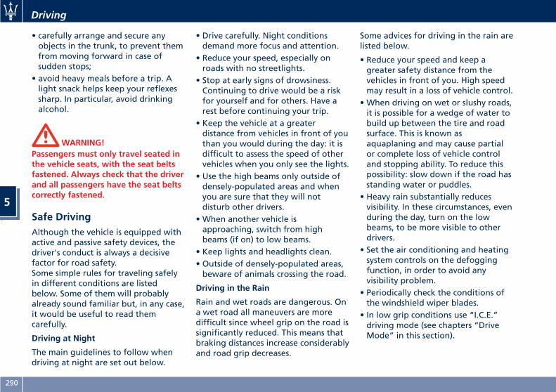
• carefully arrange and secure anyobjects in the trunk, to prevent themfrom moving forward in case ofsudden stops;
• avoid heavy meals before a trip. Alight snack helps keep your reflexessharp. In particular, avoid drinkingalcohol.
WARNING!Passengers must only travel seated inthe vehicle seats, with the seat beltsfastened. Always check that the driverand all passengers have the seat beltscorrectly fastened.
Safe DrivingAlthough the vehicle is equipped withactive and passive safety devices, thedriver's conduct is always a decisivefactor for road safety.Some simple rules for traveling safelyin different conditions are listedbelow. Some of them will probablyalready sound familiar but, in any case,it would be useful to read themcarefully.
Driving at Night
The main guidelines to follow whendriving at night are set out below.
• Drive carefully. Night conditionsdemand more focus and attention.
• Reduce your speed, especially onroads with no streetlights.
• Stop at early signs of drowsiness.Continuing to drive would be a riskfor yourself and for others. Have arest before continuing your trip.
• Keep the vehicle at a greaterdistance from vehicles in front of youthan you would during the day: it isdifficult to assess the speed of othervehicles when you only see the lights.
• Use the high beams only outside ofdensely-populated areas and whenyou are sure that they will notdisturb other drivers.
• When another vehicle isapproaching, switch from highbeams (if on) to low beams.
• Keep lights and headlights clean.• Outside of densely-populated areas,beware of animals crossing the road.
Driving in the Rain
Rain and wet roads are dangerous. Ona wet road all maneuvers are moredifficult since wheel grip on the road issignificantly reduced. This means thatbraking distances increase considerablyand road grip decreases.
Some advices for driving in the rain arelisted below.
• Reduce your speed and keep agreater safety distance from thevehicles in front of you. High speedmay result in a loss of vehicle control.
• When driving on wet or slushy roads,it is possible for a wedge of water tobuild up between the tire and roadsurface. This is known asaquaplaning and may cause partialor complete loss of vehicle controland stopping ability. To reduce thispossibility: slow down if the road hasstanding water or puddles.
• Heavy rain substantially reducesvisibility. In these circumstances, evenduring the day, turn on the lowbeams, to be more visible to otherdrivers.
• Set the air conditioning and heatingsystem controls on the defoggingfunction, in order to avoid anyvisibility problem.
• Periodically check the conditions ofthe windshield wiper blades.
• In low grip conditions use “I.C.E.”driving mode (see chapters “DriveMode” in this section).
Driving
5
290
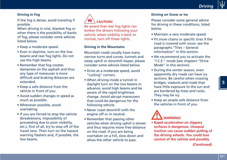
Driving in Fog
If the fog is dense, avoid traveling ifpossible.When driving in mist, blanket fog orwhen there is the possibility of banksof fog, please consider some adviceslisted below.
• Keep a moderate speed.• Even in daytime, turn on the lowbeams and rear fog lights. Do notuse the high beams.
• Remember that fog createsdampness on the asphalt and thusany type of maneuver is moredifficult and braking distances areextended.
• Keep a safe distance from thevehicle in front of you.
• Avoid sudden changes in speed asmuch as possible.
• Whenever possible, avoidovertaking.
• If you are forced to stop the vehicle(breakdowns, impossibility ofproceeding due to poor visibility,etc.), first of all, try to stop off of thetravel lane. Then turn on the hazardwarning flashers and, if possible, thelow beams.
CAUTION!Be aware that rear fog lights canbother the drivers following yourvehicle: when visibility is back tonormal, turn off these lights.
Driving in the Mountains
Mountain roads usually have manynarrow turns and curves, tunnels andsteep uphill or downhill slopes: pleaseconsider some advices listed below.
• Drive at a moderate speed, avoid“cutting” corners.
• When driving inside a tunnel indaylight turn on the low beams inadvance; avoid high beams and beaware of the rapid brightnesschange. Avoid abrupt maneuversthat could be dangerous for thefollowing vehicle.
• Never coast downhill with theengine off or in neutral.
• Remember that passing othervehicles when driving uphill is slowerand thus requires more free distanceon the road. If you are beingovertaken on a hill, slow down andallow the other vehicle to pass.
Driving on Snow or Ice
Please consider some general advicefor driving in these conditions, listedbelow.
• Maintain a very moderate speed.• Fit snow chains or specific tires if theroad is covered with snow: see theparagraphs “Tires – GeneralInformation” in this section.
• We recommend you to activate the“I.C.E.” mode (see chapters “DriveMode” in this section).
• During the winter season, evenapparently dry roads can have icysections. Be careful when crossingbridges, viaducts and roads thathave little exposure to the sun andare bordered by trees and rocks.They may be icy.
• Keep an ample safe distance fromthe vehicles in front of you.
WARNING!• Rapid acceleration on slipperysurfaces is dangerous. Unequaltraction can cause sudden pulling ofthe driving wheels. You could losecontrol of the vehicle and possibly
(Continued)
Driving
5
291
(Continued)have a collision. Accelerate slowlyand carefully whenever there islikely to be poor traction (ice, snow,wet mud, loose sand, etc.).
• Do not drive on or across a road orpath where water is flowing and/orrising (as in storm run-off). Flowingwater can wear away the road orpath surface and cause your vehicleto sink into deeper water.Furthermore, flowing and/or risingwater can carry your vehicle awayswiftly. Failure to follow thiswarning may result in injuries thatare serious or fatal to you, yourpassengers, and others around you.
Although your vehicle is capable ofdriving through shallow standingwater, consider the following Cautionsand Warnings before doing so.
CAUTION!
• Always check the depth of thestanding water before drivingthrough it. Never drive throughstanding water that is deeper than47 in (150 mm).
• Determine the condition of the roador the path that is under water and ifthere are any obstacles in the way
before driving through the standingwater.
• Do not exceed 5 mph (8 km/h) whendriving through standing water. Thiswill minimize wave effects.
• Driving through standing water maycause damage to your vehicledrivetrain components. After drivingthrough standing water, do not drive ifyou are not sure about drivetraincondition. Such damage is not coveredby the New Vehicle Warranty.
• Getting water inside your vehicleengine can cause it to lock up andstall out, and cause serious internaldamage to the engine. Such damageis not covered by the New VehicleWarranty.
• After driving through standing wateralways have the fluids (engine oil,transmission oil, etc) checked forcontamination at an AuthorizedMaserati Dealer.
WARNING!• Driving through standing waterlimits your vehicle tractioncapabilities. Do not exceed 5 mph(8 km/h) when driving throughstanding water.
• Driving through standing waterlimits your vehicle brakingcapabilities, which increasesstopping distances. Therefore, afterdriving through standing water,drive slowly and lightly press on thebrake pedal several times toprogressively dry the brakes discsand pads.
• Getting water inside your vehicleengine can cause it to lock up andstall out.
• Failure to follow these warningsmay result in injuries that are seriousor fatal to you, your passengers, andothers around you.
Driving
5
292
6 – In an Emergency
Tool Kit . . . . . . . . . . . . . . . . . . . . . . . . . . . . . . . . . . . . . . . . . . . . . . 294Hazard Warning Flashers . . . . . . . . . . . . . . . . . . . . . . . . . . . . . . . . . 295In the Event of an Accident . . . . . . . . . . . . . . . . . . . . . . . . . . . . . . . 295In case of a Punctured Tire . . . . . . . . . . . . . . . . . . . . . . . . . . . . . . . . 296Emergency Release of the Parking Brake . . . . . . . . . . . . . . . . . . . . . 301Transmission Manual Release of P (Park) Position . . . . . . . . . . . . . . . 301Auxiliary Jump-Start Procedure . . . . . . . . . . . . . . . . . . . . . . . . . . . . 302Towing a Disabled Vehicle . . . . . . . . . . . . . . . . . . . . . . . . . . . . . . . . 304
293
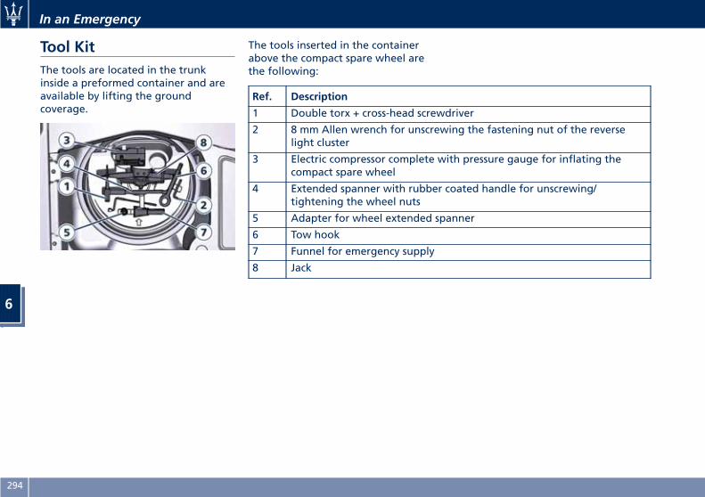
Tool KitThe tools are located in the trunkinside a preformed container and areavailable by lifting the groundcoverage.
The tools inserted in the containerabove the compact spare wheel arethe following:
Ref. Description
1 Double torx + cross-head screwdriver
2 8 mm Allen wrench for unscrewing the fastening nut of the reverselight cluster
3 Electric compressor complete with pressure gauge for inflating thecompact spare wheel
4 Extended spanner with rubber coated handle for unscrewing/tightening the wheel nuts
5 Adapter for wheel extended spanner
6 Tow hook
7 Funnel for emergency supply
8 Jack
In an Emergency
6
294
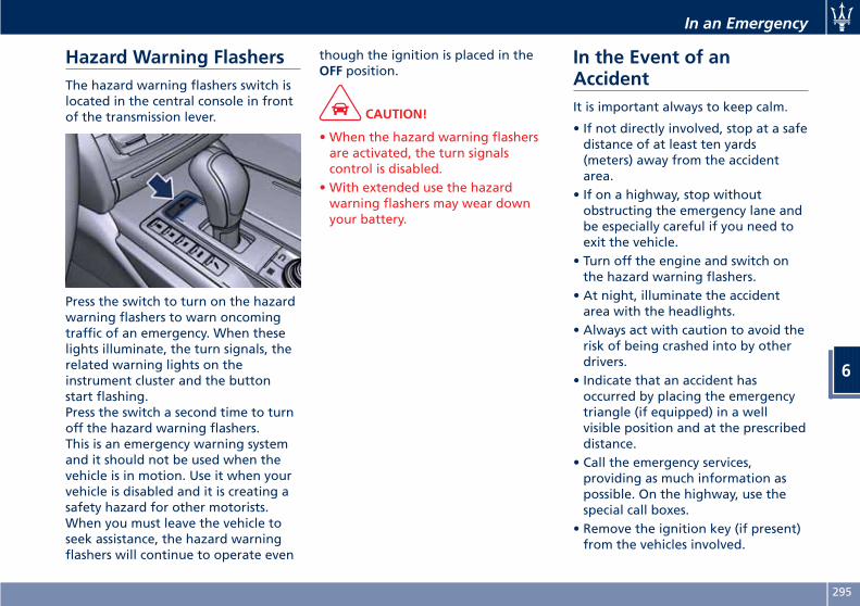
Hazard Warning FlashersThe hazard warning flashers switch islocated in the central console in frontof the transmission lever.
Press the switch to turn on the hazardwarning flashers to warn oncomingtraffic of an emergency. When theselights illuminate, the turn signals, therelated warning lights on theinstrument cluster and the buttonstart flashing.Press the switch a second time to turnoff the hazard warning flashers.This is an emergency warning systemand it should not be used when thevehicle is in motion. Use it when yourvehicle is disabled and it is creating asafety hazard for other motorists.When you must leave the vehicle toseek assistance, the hazard warningflashers will continue to operate even
though the ignition is placed in theOFF position.
CAUTION!
• When the hazard warning flashersare activated, the turn signalscontrol is disabled.
• With extended use the hazardwarning flashers may wear downyour battery.
In the Event of anAccidentIt is important always to keep calm.
• If not directly involved, stop at a safedistance of at least ten yards(meters) away from the accidentarea.
• If on a highway, stop withoutobstructing the emergency lane andbe especially careful if you need toexit the vehicle.
• Turn off the engine and switch onthe hazard warning flashers.
• At night, illuminate the accidentarea with the headlights.
• Always act with caution to avoid therisk of being crashed into by otherdrivers.
• Indicate that an accident hasoccurred by placing the emergencytriangle (if equipped) in a wellvisible position and at the prescribeddistance.
• Call the emergency services,providing as much information aspossible. On the highway, use thespecial call boxes.
• Remove the ignition key (if present)from the vehicles involved.
In an Emergency
6
295

• If fuel or other chemical products canbe smelled, do not smoke and askpeople around you to put theircigarettes out.
• To extinguish fires, even small ones,use a fire extinguisher, blankets, sandor earth. Never use water.
• In multiple accidents occurred onhighways, particularly where visibilityis poor, there is a high risk of beinginvolved in other collisions. Leave thevehicle immediately and move awayfrom the area.
In case of Injured Persons• Never leave the injured person alone.Persons not directly involved in theaccident are also required to giveassistance.
• Do not crowd around injuredpersons.
• Reassure the injured person that helpis on the way.
WARNING!California Proposition 65Operating, servicing and maintaininga passenger vehicle or off-road vehiclecan expose you to chemicals includingsuch as, engine exhaust, carbonmonoxide, phthalates and lead, that
which are know to the State ofCalifornia to cause cancer and birthdefects or other reproductive harm. Tominimize exposure, avoid breathingexhaust, do not idle the engine exceptas necessary, service your vehicle in awell-ventilated area and wear glovesor wash your hands frequently whenservicing your vehicle. For moreinformation go to:www.P65Warnings.ca.gov/passenger-vehicle
In case of a Punctured TireIf the vehicle is equipped with acompact spare wheel.
Using the Compact SpareWheel
NOTE:
The compact spare wheel is supplied inaluminium or steel: the pictures showthe one in aluminium.
The compact spare wheel is stored inthe trunk and is supplied deflated inorder to limit the amount of spaceoccupied. An electric compressor is alsoprovided for inflating. In the event ofa tire puncture, proceed as follows.
• Stop the vehicle in a place that doesnot constitute a danger to traffic andwhere the wheel can be changedsafely. The vehicle must be level andon firm ground.
• Select the P (Park) mode and thenengage manually the electric parkingbrake and move the ignition switchto OFF position.
• If necessary, turn the hazard warningflashers on and place the warningtriangle (if equipped) at the requireddistance.
In an Emergency
6
296
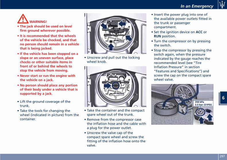
WARNING!• The jack should be used on levelfirm ground wherever possible.
• It is recommended that the wheelsof the vehicle be chocked, and thatno person should remain in a vehiclethat is being jacked.
• If the vehicle has been stopped on aslope or an uneven surface, placechocks or other suitable items infront of or behind the wheels tostop the vehicle from moving.
• Never start or run the engine withthe vehicle on a jack.
• No person should place any portionof their body under a vehicle that issupported by a jack.
• Lift the ground coverage of thetrunk.
• Take the tools for changing thewheel (indicated in picture) from thecontainer.
• Unscrew and pull out the lockingwheel knob.
• Take the container and the compactspare wheel out of the trunk.
• Remove from the compressor casethe inflation hose and the cable witha plug for the power outlet.
• Unscrew the valve cap of thecompact spare wheel and screw thefitting of the inflation hose onto thevalve.
• Insert the power plug into one ofthe available power outlets fitted inthe trunk or passengercompartment.
• Set the ignition device on ACC orRUN position.
• Turn the compressor on by pressingthe switch.
• Stop the compressor by pressing theswitch again, when the pressureindicated by the gauge reaches therecommended level (see “TireInflation Pressure” in section“Features and Specifications”) andscrew the cap on the compact sparewheel valve.
In an Emergency
6
297
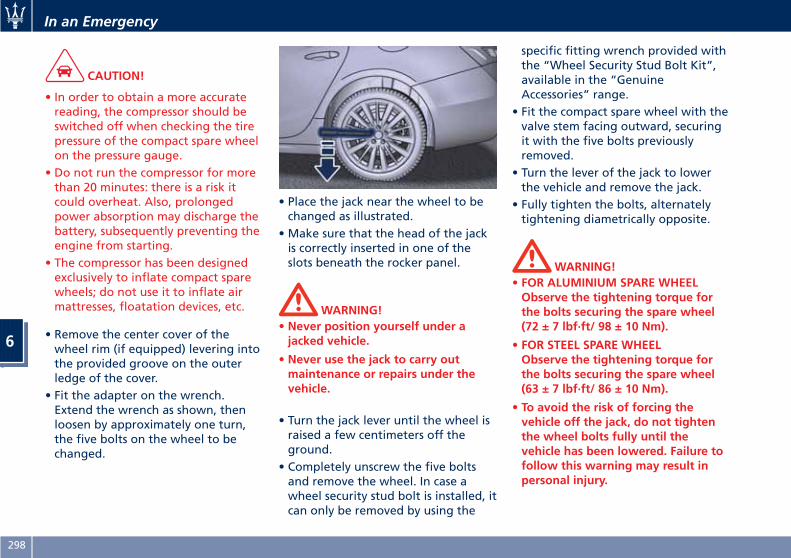
CAUTION!
• In order to obtain a more accuratereading, the compressor should beswitched off when checking the tirepressure of the compact spare wheelon the pressure gauge.
• Do not run the compressor for morethan 20 minutes: there is a risk itcould overheat. Also, prolongedpower absorption may discharge thebattery, subsequently preventing theengine from starting.
• The compressor has been designedexclusively to inflate compact sparewheels; do not use it to inflate airmattresses, floatation devices, etc.
• Remove the center cover of thewheel rim (if equipped) levering intothe provided groove on the outerledge of the cover.
• Fit the adapter on the wrench.Extend the wrench as shown, thenloosen by approximately one turn,the five bolts on the wheel to bechanged.
• Place the jack near the wheel to bechanged as illustrated.
• Make sure that the head of the jackis correctly inserted in one of theslots beneath the rocker panel.
WARNING!• Never position yourself under ajacked vehicle.
• Never use the jack to carry outmaintenance or repairs under thevehicle.
• Turn the jack lever until the wheel israised a few centimeters off theground.
• Completely unscrew the five boltsand remove the wheel. In case awheel security stud bolt is installed, itcan only be removed by using the
specific fitting wrench provided withthe “Wheel Security Stud Bolt Kit”,available in the “GenuineAccessories” range.
• Fit the compact spare wheel with thevalve stem facing outward, securingit with the five bolts previouslyremoved.
• Turn the lever of the jack to lowerthe vehicle and remove the jack.
• Fully tighten the bolts, alternatelytightening diametrically opposite.
WARNING!• FOR ALUMINIUM SPARE WHEELObserve the tightening torque forthe bolts securing the spare wheel(72 ± 7 lbf·ft/ 98 ± 10 Nm).
• FOR STEEL SPARE WHEELObserve the tightening torque forthe bolts securing the spare wheel(63 ± 7 lbf·ft/ 86 ± 10 Nm).
• To avoid the risk of forcing thevehicle off the jack, do not tightenthe wheel bolts fully until thevehicle has been lowered. Failure tofollow this warning may result inpersonal injury.
In an Emergency
6
298
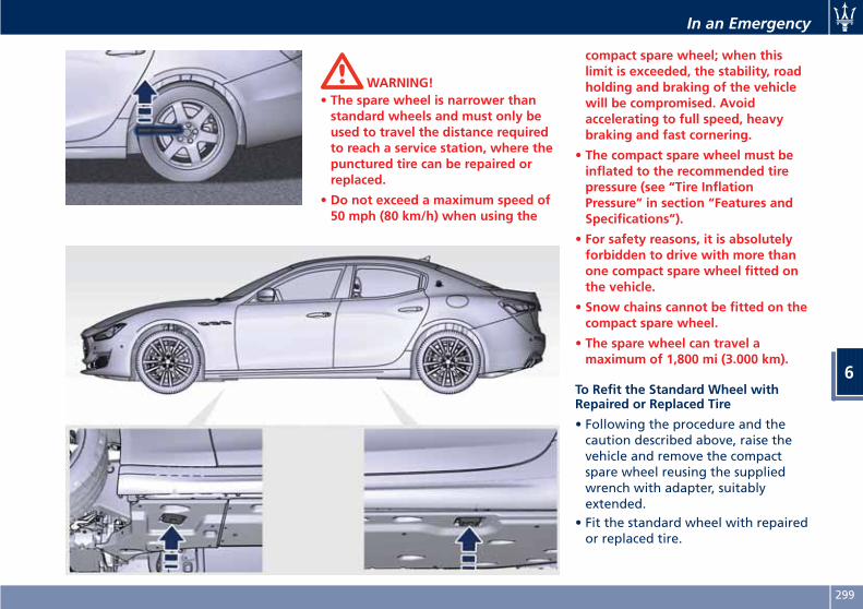
WARNING!• The spare wheel is narrower thanstandard wheels and must only beused to travel the distance requiredto reach a service station, where thepunctured tire can be repaired orreplaced.
• Do not exceed a maximum speed of50 mph (80 km/h) when using the
compact spare wheel; when thislimit is exceeded, the stability, roadholding and braking of the vehiclewill be compromised. Avoidaccelerating to full speed, heavybraking and fast cornering.
• The compact spare wheel must beinflated to the recommended tirepressure (see “Tire InflationPressure” in section “Features andSpecifications”).
• For safety reasons, it is absolutelyforbidden to drive with more thanone compact spare wheel fitted onthe vehicle.
• Snow chains cannot be fitted on thecompact spare wheel.
• The spare wheel can travel amaximum of 1,800 mi (3.000 km).
To Refit the Standard Wheel withRepaired or Replaced Tire
• Following the procedure and thecaution described above, raise thevehicle and remove the compactspare wheel reusing the suppliedwrench with adapter, suitablyextended.
• Fit the standard wheel with repairedor replaced tire.
In an Emergency
6
299
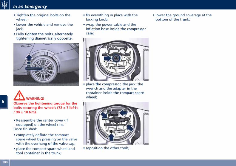
• Tighten the original bolts on thewheel.
• Lower the vehicle and remove thejack.
• Fully tighten the bolts, alternatelytightening diametrically opposite.
WARNING!Observe the tightening torque for thebolts securing the wheels (72 ± 7 lbf·ft/ 98 ± 10 Nm).
• Reassemble the center cover (ifequipped) on the wheel rim.
Once finished:
• completely deflate the compactspare wheel by pressing on the valvewith the overhang of the valve cap;
• place the compact spare wheel andtool container in the trunk;
• fix everything in place with thelocking knob;
• wrap the power cable and theinflation hose inside the compressorcase;
• place the compressor, the jack, thewrench and the adapter in thecontainer inside the compact sparewheel;
• reposition the other tools;
• lower the ground coverage at thebottom of the trunk.
In an Emergency
6
300
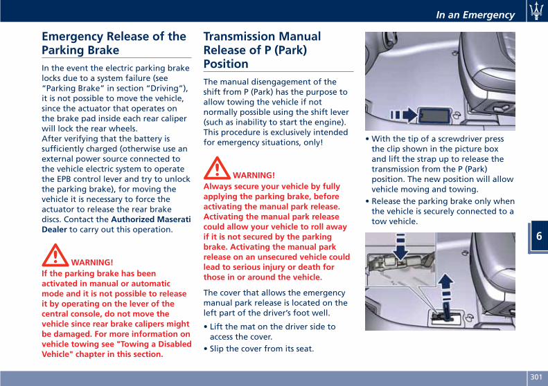
Emergency Release of theParking BrakeIn the event the electric parking brakelocks due to a system failure (see“Parking Brake” in section “Driving”),it is not possible to move the vehicle,since the actuator that operates onthe brake pad inside each rear caliperwill lock the rear wheels.After verifying that the battery issufficiently charged (otherwise use anexternal power source connected tothe vehicle electric system to operatethe EPB control lever and try to unlockthe parking brake), for moving thevehicle it is necessary to force theactuator to release the rear brakediscs. Contact the Authorized MaseratiDealer to carry out this operation.
WARNING!If the parking brake has beenactivated in manual or automaticmode and it is not possible to releaseit by operating on the lever of thecentral console, do not move thevehicle since rear brake calipers mightbe damaged. For more information onvehicle towing see "Towing a DisabledVehicle" chapter in this section.
Transmission ManualRelease of P (Park)PositionThe manual disengagement of theshift from P (Park) has the purpose toallow towing the vehicle if notnormally possible using the shift lever(such as inability to start the engine).This procedure is exclusively intendedfor emergency situations, only!
WARNING!Always secure your vehicle by fullyapplying the parking brake, beforeactivating the manual park release.Activating the manual park releasecould allow your vehicle to roll awayif it is not secured by the parkingbrake. Activating the manual parkrelease on an unsecured vehicle couldlead to serious injury or death forthose in or around the vehicle.
The cover that allows the emergencymanual park release is located on theleft part of the driver’s foot well.
• Lift the mat on the driver side toaccess the cover.
• Slip the cover from its seat.
• With the tip of a screwdriver pressthe clip shown in the picture boxand lift the strap up to release thetransmission from the P (Park)position. The new position will allowvehicle moving and towing.
• Release the parking brake only whenthe vehicle is securely connected to atow vehicle.
In an Emergency
6
301
Auxiliary Jump-StartProcedureIf your vehicle has a discharged batteryit can be jump-started using a set ofjumper cables and a battery of anothervehicle or by using a portable batterybooster. It is necessary to have properjumper cables in order to connect thebooster battery to the remote posts ofthe discharged battery. Booster cableshave positive and negative terminalclamps and are identified by thesheath color (red = positive, black =negative).
NOTE:
An Authorized Maserati Dealer canprovide you with information aboutthe “Maserati Jumper Cables Kit”,available in the “Genuine Accessories”range.
Jump-starting can be dangerous ifdone improperly so please follow theprocedures in this section carefully.
NOTE:
When using a portable battery boosterpack, follow the batterymanufacturer’s operating instructionsand precautions.
CAUTION!
• To jump start a vehicle do not use aportable battery, a booster pack orany other booster source with asystem voltage greater than 14 Voltsor damage to the battery, startermotor, alternator or electrical systemof the vehicle with the dischargedbattery may occur.
• Do not use a battery charger foremergency starting under anycircumstances. You could damage theelectronic systems, particularly thecontrol units managing the ignitionand fuel supply functions.
• If the battery is completelydischarged when the windows arefully raised, open the door with theutmost care; do not close the dooragain until it is possible to lower thewindow.
WARNING!Always secure your vehicle by fullyapplying the parking brake, beforeactivating the manual park release.Activating the manual park releasecould allow your vehicle to roll away
if it is not secured by the parkingbrake. Activating the manual parkrelease on an unsecured vehicle couldlead to serious injury or death forthose in or around the vehicle.
NOTE:
If you need to disconnect the batteryfrom the vehicle electrical system, see“Maintenance — Free Battery” insection “Maintenance and Care”).
WARNING!California Proposition 65Operating, servicing and maintaininga passenger vehicle or off-road vehiclecan expose you to chemicals includingsuch as, engine exhaust, carbonmonoxide, phthalates and lead, thatwhich are know to the State ofCalifornia to cause cancer and birthdefects or other reproductive harm. Tominimize exposure, avoid breathingexhaust, do not idle the engine exceptas necessary, service your vehicle in awell-ventilated area and wear glovesor wash your hands frequently whenservicing your vehicle. For moreinformation go to:
In an Emergency
6
302
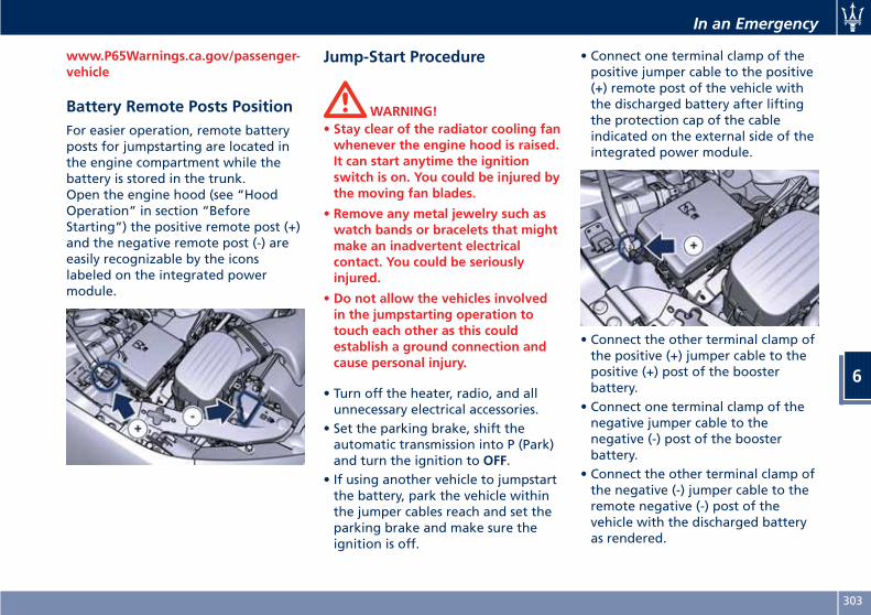
www.P65Warnings.ca.gov/passenger-vehicle
Battery Remote Posts PositionFor easier operation, remote batteryposts for jumpstarting are located inthe engine compartment while thebattery is stored in the trunk.Open the engine hood (see “HoodOperation” in section “BeforeStarting”) the positive remote post (+)and the negative remote post (-) areeasily recognizable by the iconslabeled on the integrated powermodule.
Jump-Start Procedure
WARNING!• Stay clear of the radiator cooling fanwhenever the engine hood is raised.It can start anytime the ignitionswitch is on. You could be injured bythe moving fan blades.
• Remove any metal jewelry such aswatch bands or bracelets that mightmake an inadvertent electricalcontact. You could be seriouslyinjured.
• Do not allow the vehicles involvedin the jumpstarting operation totouch each other as this couldestablish a ground connection andcause personal injury.
• Turn off the heater, radio, and allunnecessary electrical accessories.
• Set the parking brake, shift theautomatic transmission into P (Park)and turn the ignition to OFF.
• If using another vehicle to jumpstartthe battery, park the vehicle withinthe jumper cables reach and set theparking brake and make sure theignition is off.
• Connect one terminal clamp of thepositive jumper cable to the positive(+) remote post of the vehicle withthe discharged battery after liftingthe protection cap of the cableindicated on the external side of theintegrated power module.
• Connect the other terminal clamp ofthe positive (+) jumper cable to thepositive (+) post of the boosterbattery.
• Connect one terminal clamp of thenegative jumper cable to thenegative (-) post of the boosterbattery.
• Connect the other terminal clamp ofthe negative (-) jumper cable to theremote negative (-) post of thevehicle with the discharged batteryas rendered.
In an Emergency
6
303
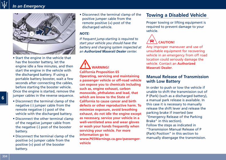
• Start the engine in the vehicle thathas the booster battery, let theengine idle a few minutes, and thenstart the engine in the vehicle withthe discharged battery. If using aportable battery booster, wait a fewseconds after connecting the cables,before starting the booster vehicle.
Once the engine is started, remove thejumper cables in the reverse sequence.
• Disconnect the terminal clamp of thenegative (-) jumper cable from theremote negative (-) post of thevehicle with the discharged battery.
• Disconnect the other terminal clampof the negative jumper cable fromthe negative (-) post of the boosterbattery.
• Disconnect the terminal clamp of thepositive (+) jumper cable from thepositive (+) post of the boosterbattery.
• Disconnect the terminal clamp of thepositive jumper cable from theremote positive (+) post of thedischarged vehicle.
NOTE:
If frequent jump-starting is required tostart your vehicle you should have thebattery and charging system inspected atan Authorized Maserati Dealer center.
WARNING!California Proposition 65Operating, servicing and maintaininga passenger vehicle or off-road vehiclecan expose you to chemicals includingsuch as, engine exhaust, carbonmonoxide, phthalates and lead, thatwhich are know to the State ofCalifornia to cause cancer and birthdefects or other reproductive harm. Tominimize exposure, avoid breathingexhaust, do not idle the engine exceptas necessary, service your vehicle in awell-ventilated area and wear glovesor wash your hands frequently whenservicing your vehicle. For moreinformation go to:www.P65Warnings.ca.gov/passenger-vehicle
Towing a Disabled VehicleProper towing or lifting equipment isrequired to prevent damage to yourvehicle.
CAUTION!Any improper maneuver and use ofunsuitable equipment for recoveringvehicle in an emergency from off roadlocation could seriously damage thevehicle. Contact an AuthorizedMaserati Dealer.
Manual Release of Transmissionwith Low BatteryIn order to push or tow the vehicle ifunable to shift the transmission out ofP (Park) (such as a discharged battery),a manual park release is available. Inthis case it is necessary to manuallyrelease the shift lever and release theparking brake if inserted (see“Emergency Release of the ParkingBrake” in this section).Follow the steps as indicated in“Transmission Manual Release of P(Park) Position” in this section tomanually disengage the transmission.
In an Emergency
6
304
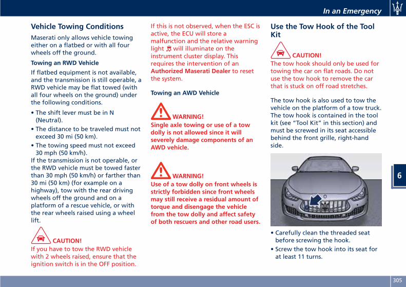
Vehicle Towing ConditionsMaserati only allows vehicle towingeither on a flatbed or with all fourwheels off the ground.
Towing an RWD Vehicle
If flatbed equipment is not available,and the transmission is still operable, aRWD vehicle may be flat towed (withall four wheels on the ground) underthe following conditions.
• The shift lever must be in N(Neutral).
• The distance to be traveled must notexceed 30 mi (50 km).
• The towing speed must not exceed30 mph (50 km/h).
If the transmission is not operable, orthe RWD vehicle must be towed fasterthan 30 mph (50 km/h) or farther than30 mi (50 km) (for example on ahighway), tow with the rear drivingwheels off the ground and on aplatform of a rescue vehicle, or withthe rear wheels raised using a wheellift.
CAUTION!If you have to tow the RWD vehiclewith 2 wheels raised, ensure that theignition switch is in the OFF position.
If this is not observed, when the ESC isactive, the ECU will store amalfunction and the relative warninglight will illuminate on theinstrument cluster display. Thisrequires the intervention of anAuthorized Maserati Dealer to resetthe system.
Towing an AWD Vehicle
WARNING!Single axle towing or use of a towdolly is not allowed since it willseverely damage components of anAWD vehicle.
WARNING!Use of a tow dolly on front wheels isstrictly forbidden since front wheelsmay still receive a residual amount oftorque and disengage the vehiclefrom the tow dolly and affect safetyof both rescuers and other road users.
Use the Tow Hook of the ToolKit
CAUTION!The tow hook should only be used fortowing the car on flat roads. Do notuse the tow hook to remove the carthat is stuck on off road stretches.
The tow hook is also used to tow thevehicle on the platform of a tow truck.The tow hook is contained in the toolkit (see “Tool Kit” in this section) andmust be screwed in its seat accessiblebehind the front grille, right-handside.
• Carefully clean the threaded seatbefore screwing the hook.
• Screw the tow hook into its seat forat least 11 turns.
In an Emergency
6
305
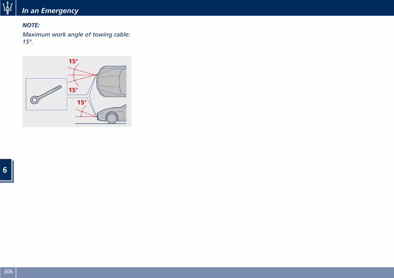
NOTE:
Maximum work angle of towing cable:15°.
In an Emergency
6
306
7 – Maintenance and Care
Scheduled Maintenance Service . . . . . . . . . . . . . . . . . . . . . . . . . . . . 308Scheduled Service Plan . . . . . . . . . . . . . . . . . . . . . . . . . . . . . . . . . . . 309Maintenance Procedures . . . . . . . . . . . . . . . . . . . . . . . . . . . . . . . . . 314Maintenance-Free Battery . . . . . . . . . . . . . . . . . . . . . . . . . . . . . . . . 322Fuse Replacement . . . . . . . . . . . . . . . . . . . . . . . . . . . . . . . . . . . . . . 327Bulb Replacement . . . . . . . . . . . . . . . . . . . . . . . . . . . . . . . . . . . . . . 334A/C System Maintenance . . . . . . . . . . . . . . . . . . . . . . . . . . . . . . . . . 338Wheels Maintenance . . . . . . . . . . . . . . . . . . . . . . . . . . . . . . . . . . . . 339Bodywork Maintenance and Care . . . . . . . . . . . . . . . . . . . . . . . . . . 341Interior Maintenance and Care . . . . . . . . . . . . . . . . . . . . . . . . . . . . 344Vehicle Stored for Long Periods . . . . . . . . . . . . . . . . . . . . . . . . . . . . 345Restarting the Vehicle . . . . . . . . . . . . . . . . . . . . . . . . . . . . . . . . . . . 345Battery Statement . . . . . . . . . . . . . . . . . . . . . . . . . . . . . . . . . . . . . . 346
307
Scheduled MaintenanceServiceCorrect maintenance is clearly the bestway to guarantee vehicle performanceand safety features, ensure respect forthe environment and low operatingcosts.
NOTE:
Also remember that the observance ofthe maintenance procedures isessential for keeping your vehicleoperating properly. Not adhering tothe “Scheduled Service Plan” canimpact your vehicle’s warranty.
Interval Running CouponsMaserati has therefore provided for aseries of checks and maintenanceoperations involving the 1st servicewhen the vehicle mileage reaches12,500 mi (20,000 km) or after 1 yearof the vehicle's life, and subsequentlyevery 12,500 mi (20,000 km) or everyyear.After the 6th service, maintenancemust be restarted with the operationsscheduled for the 1st, 2nd and 3rd
service.
CAUTION!The Scheduled Maintenance servicesare prescribed by the Manufacturer.Failure to have the services carried outcan affect your warranty.
The Scheduled Maintenance service isprovided by an Authorized MaseratiDealer. In the event that, when aservice is performed, furtherreplacements or repairs are found tobe necessary in addition to thescheduled operations, these can becarried out only with the specificconsent of the Customer.
CAUTION!You are advised to notify theAuthorized Maserati Dealer of anyminor operating problem, withoutwaiting for the next scheduled service.
NOTE:• Change your vehicle's oil if it hasbeen 1 year since your last oilchange.
• Change your engine oil more often ifyou drive your vehicle off-road for anextended period of time or shorttrips without reaching operatingtemperature.
• Under no circumstances should oilchange intervals exceed 12,500 mi(20,000 km) or at least after 1 year.
CAUTION!Failure to perform the requiredmaintenance items may result indamage to the vehicle.
Scheduled Maintenance(Service) IndicatorThe service indicator system willremind you the deadline for themaintenance program.The indicator light on theinstrument cluster flashes for approx. 5seconds displaying the message backedby a beeping sound, indicating thatthe next scheduled maintenance is dueor has already overdue (see paragraph”TFT Display: Warning/Indicator Lightsof the Set Modes/ Functions” inchapter “Instrument Cluster” ofsection “Dashboard Instruments andControls” for more details).
Maintenance and Care
7
308
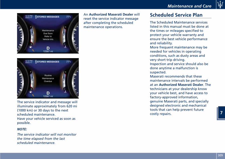
The service indicator and message willilluminate approximately from 620 mi(1000 km) or 30 days to the nextscheduled maintenance.Have your vehicle serviced as soon aspossible.
NOTE:
The service indicator will not monitorthe time elapsed from the lastscheduled maintenance.
An Authorized Maserati Dealer willreset the service indicator messageafter completing the scheduledmaintenance operations.
Scheduled Service PlanThe Scheduled Maintenance serviceslisted in this manual must be done atthe times or mileages specified toprotect your vehicle warranty andensure the best vehicle performanceand reliability.More frequent maintenance may beneeded for vehicles in operatingconditions, such as dusty areas andvery short trip driving.Inspection and service should also bedone anytime a malfunction issuspected.Maserati recommends that thesemaintenance intervals be performedat an Authorized Maserati Dealer. Thetechnicians at your dealership knowyour vehicle best, and have access tofactory-approved information,genuine Maserati parts, and speciallydesigned electronic and mechanicaltools that can help prevent futurecostly repairs.
Maintenance and Care
7
309
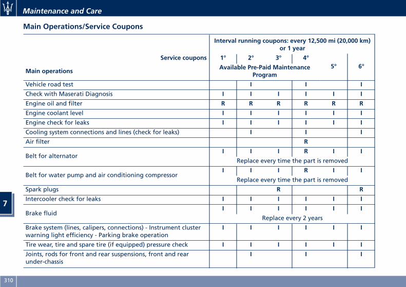
Main Operations/Service Coupons
Interval running coupons: every 12,500 mi (20,000 km)or 1 year
Service coupons 1° 2° 3° 4°5° 6°
Main operationsAvailable Pre-Paid Maintenance
Program
Vehicle road test I I I
Check with Maserati Diagnosis I I I I I I
Engine oil and filter R R R R R R
Engine coolant level I I I I I I
Engine check for leaks I I I I I I
Cooling system connections and lines (check for leaks) I I I
Air filter R
Belt for alternatorI I I R I I
Replace every time the part is removed
Belt for water pump and air conditioning compressorI I I R I I
Replace every time the part is removed
Spark plugs R R
Intercooler check for leaks I I I I I I
Brake fluidI I I I I I
Replace every 2 years
Brake system (lines, calipers, connections) - Instrument clusterwarning light efficiency - Parking brake operation
I I I I I I
Tire wear, tire and spare tire (if equipped) pressure check I I I I I I
Joints, rods for front and rear suspensions, front and rearunder-chassis
I I I
Maintenance and Care
7
310
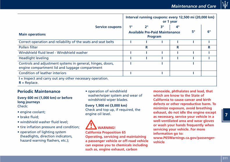
Interval running coupons: every 12,500 mi (20,000 km)or 1 year
Service coupons 1° 2° 3° 4°5° 6°
Main operationsAvailable Pre-Paid Maintenance
Program
Correct operation and reliability of the seats and seat belts I I I I I I
Pollen filter R R R
Windshield fluid level - Windshield washer I I I I I I
Headlight leveling I I I I I I
Controls and adjustment systems in general, hinges, doors,engine compartment lid and luggage compartment
I I I
Condition of leather interiors I I I
I = Inspect and carry out any other necessary operation.R = Replace.
Periodic MaintenanceEvery 600 mi (1,000 km) or beforelong journeysCheck:
• engine coolant;• brake fluid;• windshield washer fluid level;• tire inflation pressure and condition;• operation of lighting system(headlights, direction indicators,hazard warning flashers, etc.);
• operation of windshieldwasher/wiper system and wear ofwindshield wiper blades.
Every 1,900 mi (3,000 km)Check and top up, if required, theengine oil level.
WARNING!California Proposition 65Operating, servicing and maintaininga passenger vehicle or off-road vehiclecan expose you to chemicals includingsuch as, engine exhaust, carbon
monoxide, phthalates and lead, thatwhich are know to the State ofCalifornia to cause cancer and birthdefects or other reproductive harm. Tominimize exposure, avoid breathingexhaust, do not idle the engine exceptas necessary, service your vehicle in awell-ventilated area and wear glovesor wash your hands frequently whenservicing your vehicle. For moreinformation go to:www.P65Warnings.ca.gov/passenger-vehicle
Maintenance and Care
7
311
Heavy-Duty Vehicle UseIf the car is mainly used under one ofthe following conditions:
• off-road;• short, repeated journeys (less than4-5 mi/7-8 km) at sub-zero outsidetemperatures;
• engine often idling or driving longdistances at low speeds or longperiods of idleness;
you should perform the followinginspections more frequently thanrecommended on the “ScheduledService Plan”:
• check front disc brake pad conditionsand wear;
• check cleanliness of hood and trunklocks, cleanliness and lubrication oflinkage;
• visually inspect conditions of: engine,transmission, pipes and hoses(exhaust - fuel system - brakes) andrubber elements (boots - sleeves -bushes - etc.);
• check battery charge;• visually inspect condition of theaccessory drive belts;
• check and, if necessary, changeengine oil and replace oil filter;
• check and, if necessary, replacepollen filter of the A/C system;
• check and, if necessary, replace aircleaner filter.
CAUTION!All maintenance operations for thevehicle must be carried out by anAuthorized Maserati Dealer. Forroutine and minor maintenanceoperations which you can carry outyourself, make sure that you have thenecessary experience and always usesuitable equipment, originalMaseratispare parts and the prescribed fluids.Shall this not be the case, do not carryany operation on your own andcontact an Authorized MaseratiDealer.
On Board Diagnostic SystemYour vehicle is equipped with asophisticated on board diagnosticsystem called OBD II. This systemmonitors the performance of theemissions, engine, and automatictransmission control systems. Whenthese systems are operating properly,your vehicle will provide excellentperformance and fuel economy, aswell as engine emissions suited tocurrent government regulations.If any of these systems require service,the OBD II system will turn on theMalfunction Indicator Light on theinstrument cluster display (refer to“Instrument Cluster” in section“Dashboard Instruments andControls”). The system stores as welldiagnostic codes and otherinformation to assist your servicetechnician by performing repairs.Although the vehicle will be driveableand will not need towing, contact anAuthorized Maserati Dealer for serviceas soon as possible.
CAUTION!
• Prolonged driving with the MILon could cause further damage tothe emissions control system. It could
Maintenance and Care
7
312
also affect fuel economy anddriveability. The vehicle must beserviced before any emissions testscan be performed.
• If the MIL is flashing while theengine is running, severe catalyticconverter damage and power losswill soon occur. Immediate service atan Authorized Maserati Dealer isrequired.
Emissions Inspection andMaintenance ProgramsIn some localities, it may be a legalrequirement to pass an inspection ofyour vehicle's emissions controlsystem. Failure to pass could preventvehicle registration. For states thatrequire an Inspection andMaintenance (I/M), this check verifiesthe “Malfunction Indicator Light ”is functioning and is not on when theengine is running, and that the OBD IIsystem is ready for testing.Normally, the OBD II system will beready. The OBD II system may not beready if your vehicle was recentlyserviced, recently had a dead batteryor a battery replacement. If the OBD IIsystem should be determined notready for the I/M test, your vehiclemay fail the test.
To check if your vehicle's OBD II systemis ready, you must do the following:
1. Press the ignition device to theRUN position, but do not crank orstart the engine.
2. As soon as you press the ignitiondevice to turn the engine On, youwill see the MIL remainilluminated for 15 seconds, this is anormal bulb check.
3. Approximately 15 seconds later,one of two things will happen:•The MIL will remainilluminated and a message errorwill appear on your instrumentcluster. This means that yourvehicle's OBD II system is notready and you should notproceed to the I/M station.
•The MIL will turn Off. Thismeans that your vehicle's OBD IIsystem is ready and you canproceed to the I/M station.
If your OBD II system is not ready, youshould see an Authorized MaseratiDealer or repair facility. If your vehiclewas recently serviced or had a batteryfailure or replacement, you may needto do nothing more than drive yourvehicle as you normally would in order
for your OBD II system to update. Arecheck with the above test routinemay then indicate that the system isnow ready.Regardless of whether your vehicle'sOBD II system is ready or not, if theMIL is illuminated during normalvehicle operation you should haveyour vehicle serviced before going tothe I/M station. The I/M station can failyour vehicle because the MIL is onwith the engine running.
Spare PartsUse of genuine Maserati parts fornormal or scheduled maintenance andrepairs is highly recommended toensure excellent performance.Damage or failures caused bynon-genuine spare parts used formaintenance and repairs will not becovered by the manufacturer's warranty.
Dealer ServiceAn Authorized Maserati Dealer hasthe qualified service personnel, specialtools, and equipment to perform allservice operations in an expertmanner. Service Manuals are availablewhich include detailed serviceinformation for your vehicle. Refer tothese Service Manuals beforeattempting any procedure yourself.
Maintenance and Care
7
313
Intentional tampering with emissionscontrol systems may void yourwarranty and could result in civilpenalties.
WARNING!You can be badly injured working onor around a motor vehicle. Take yourvehicle to an Authorized MaseratiDealer.
WARNING!California Proposition 65Operating, servicing and maintaininga passenger vehicle or off-road vehiclecan expose you to chemicals includingsuch as, engine exhaust, carbonmonoxide, phthalates and lead, thatwhich are know to the State ofCalifornia to cause cancer and birthdefects or other reproductive harm. Tominimize exposure, avoid breathingexhaust, do not idle the engine exceptas necessary, service your vehicle in awell-ventilated area and wear glovesor wash your hands frequently whenservicing your vehicle. For moreinformation go to:www.P65Warnings.ca.gov/passenger-vehicle
Maintenance ProceduresThe following pages contain the“required” maintenance standardsdetermined by Maserati engineers.Besides those maintenance itemsspecified in the “Scheduled ServicePlan”, there are other componentswhich may require service orreplacement in the future.To perform most of the services, it isnecessary to open the hood (see“Hood Operation” in section “BeforeStarting”).The following images show theposition of the components involved inthe maintenance service.
CAUTION!
• Failure to properly maintain yourvehicle or perform repairs and servicewhen necessary could result in morecostly repairs, damage to othercomponents or negatively impactvehicle performance. Immediatelyhave potential malfunctionsexamined by an Authorized MaseratiDealer or a qualified repair center.
• Your vehicle has been equipped withimproved fluids that protect theperformance and durability of your
vehicle and also allow extendedmaintenance intervals. Do not usechemical flushes for washing as thechemicals can damage your engine,transmission, power steering or airconditioning. Such damages are notcovered by the New Vehicle LimitedWarranty. If a flush is neededbecause of component malfunction,use only the specified fluid for theflushing procedure.
Maintenance ServiceComponents
1 Engine oil dipstick.
2 Engine oil filler neck.
3 Air cleaner filters.
4 Engine coolant expansionreservoir cap.
5 Coolant reservoir cap fortransmission cooling system.
6 Washer fluid reservoir cap.
7 Brake fluid reservoir accesscover.
8 A/C pollen filter access cover.
9 Integrated power module(fuses).
Maintenance and Care
7
314
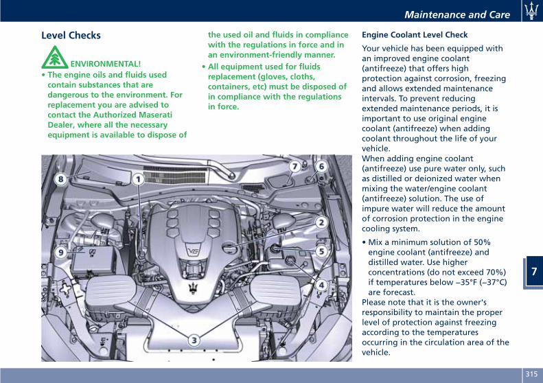
Level Checks
ENVIRONMENTAL!• The engine oils and fluids usedcontain substances that aredangerous to the environment. Forreplacement you are advised tocontact the Authorized MaseratiDealer, where all the necessaryequipment is available to dispose of
the used oil and fluids in compliancewith the regulations in force and inan environment-friendly manner.
• All equipment used for fluidsreplacement (gloves, cloths,containers, etc) must be disposed ofin compliance with the regulationsin force.
Engine Coolant Level Check
Your vehicle has been equipped withan improved engine coolant(antifreeze) that offers highprotection against corrosion, freezingand allows extended maintenanceintervals. To prevent reducingextended maintenance periods, it isimportant to use original enginecoolant (antifreeze) when addingcoolant throughout the life of yourvehicle.When adding engine coolant(antifreeze) use pure water only, suchas distilled or deionized water whenmixing the water/engine coolant(antifreeze) solution. The use ofimpure water will reduce the amountof corrosion protection in the enginecooling system.
• Mix a minimum solution of 50%engine coolant (antifreeze) anddistilled water. Use higherconcentrations (do not exceed 70%)if temperatures below −35°F (−37°C)are forecast.
Please note that it is the owner'sresponsibility to maintain the properlevel of protection against freezingaccording to the temperaturesoccurring in the circulation area of thevehicle.
Maintenance and Care
7
315
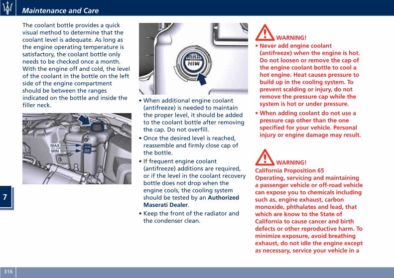
The coolant bottle provides a quickvisual method to determine that thecoolant level is adequate. As long asthe engine operating temperature issatisfactory, the coolant bottle onlyneeds to be checked once a month.With the engine off and cold, the levelof the coolant in the bottle on the leftside of the engine compartmentshould be between the rangesindicated on the bottle and inside thefiller neck.
• When additional engine coolant(antifreeze) is needed to maintainthe proper level, it should be addedto the coolant bottle after removingthe cap. Do not overfill.
• Once the desired level is reached,reassemble and firmly close cap ofthe bottle.
• If frequent engine coolant(antifreeze) additions are required,or if the level in the coolant recoverybottle does not drop when theengine cools, the cooling systemshould be tested by an AuthorizedMaserati Dealer.
• Keep the front of the radiator andthe condenser clean.
WARNING!• Never add engine coolant(antifreeze) when the engine is hot.Do not loosen or remove the cap ofthe engine coolant bottle to cool ahot engine. Heat causes pressure tobuild up in the cooling system. Toprevent scalding or injury, do notremove the pressure cap while thesystem is hot or under pressure.
•When adding coolant do not use apressure cap other than the onespecified for your vehicle. Personalinjury or engine damage may result.
WARNING!California Proposition 65Operating, servicing and maintaininga passenger vehicle or off-road vehiclecan expose you to chemicals includingsuch as, engine exhaust, carbonmonoxide, phthalates and lead, thatwhich are know to the State ofCalifornia to cause cancer and birthdefects or other reproductive harm. Tominimize exposure, avoid breathingexhaust, do not idle the engine exceptas necessary, service your vehicle in a
Maintenance and Care
7
316
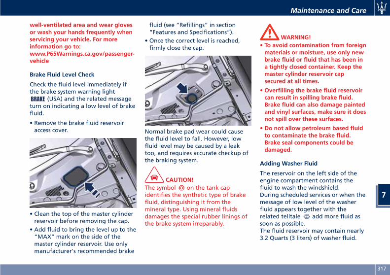
well-ventilated area and wear glovesor wash your hands frequently whenservicing your vehicle. For moreinformation go to:www.P65Warnings.ca.gov/passenger-vehicle
Brake Fluid Level Check
Check the fluid level immediately ifthe brake system warning light
(USA) and the related messageturn on indicating a low level of brakefluid.
• Remove the brake fluid reservoiraccess cover.
• Clean the top of the master cylinderreservoir before removing the cap.
• Add fluid to bring the level up to the“MAX” mark on the side of themaster cylinder reservoir. Use onlymanufacturer's recommended brake
fluid (see “Refillings” in section“Features and Specifications”).
• Once the correct level is reached,firmly close the cap.
Normal brake pad wear could causethe fluid level to fall. However, lowfluid level may be caused by a leaktoo, and requires accurate checkup ofthe braking system.
CAUTION!The symbol on the tank capidentifies the synthetic type of brakefluid, distinguishing it from themineral type. Using mineral fluidsdamages the special rubber linings ofthe brake system irreparably.
WARNING!• To avoid contamination from foreignmaterials or moisture, use only newbrake fluid or fluid that has been ina tightly closed container. Keep themaster cylinder reservoir capsecured at all times.
• Overfilling the brake fluid reservoircan result in spilling brake fluid.Brake fluid can also damage paintedand vinyl surfaces, make sure it doesnot spill over these surfaces.
• Do not allow petroleum based fluidto contaminate the brake fluid.Brake seal components could bedamaged.
Adding Washer Fluid
The reservoir on the left side of theengine compartment contains thefluid to wash the windshield.During scheduled services or when themessage of low level of the washerfluid appears together with therelated telltale add more fluid assoon as possible.The fluid reservoir may contain nearly3.2 Quarts (3 liters) of washer fluid.
Maintenance and Care
7
317
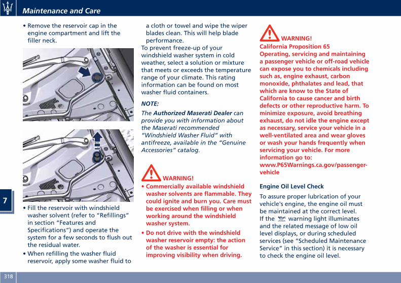
• Remove the reservoir cap in theengine compartment and lift thefiller neck.
• Fill the reservoir with windshieldwasher solvent (refer to “Refillings”in section “Features andSpecifications”) and operate thesystem for a few seconds to flush outthe residual water.
• When refilling the washer fluidreservoir, apply some washer fluid to
a cloth or towel and wipe the wiperblades clean. This will help bladeperformance.
To prevent freeze-up of yourwindshield washer system in coldweather, select a solution or mixturethat meets or exceeds the temperaturerange of your climate. This ratinginformation can be found on mostwasher fluid containers.
NOTE:
The Authorized Maserati Dealer canprovide you with information aboutthe Maserati recommended“Windshield Washer Fluid” withantifreeze, available in the “GenuineAccessories” catalog.
WARNING!• Commercially available windshieldwasher solvents are flammable. Theycould ignite and burn you. Care mustbe exercised when filling or whenworking around the windshieldwasher system.
• Do not drive with the windshieldwasher reservoir empty: the actionof the washer is essential forimproving visibility when driving.
WARNING!California Proposition 65Operating, servicing and maintaininga passenger vehicle or off-road vehiclecan expose you to chemicals includingsuch as, engine exhaust, carbonmonoxide, phthalates and lead, thatwhich are know to the State ofCalifornia to cause cancer and birthdefects or other reproductive harm. Tominimize exposure, avoid breathingexhaust, do not idle the engine exceptas necessary, service your vehicle in awell-ventilated area and wear glovesor wash your hands frequently whenservicing your vehicle. For moreinformation go to:www.P65Warnings.ca.gov/passenger-vehicle
Engine Oil Level Check
To assure proper lubrication of yourvehicle's engine, the engine oil mustbe maintained at the correct level.If the warning light illuminatesand the related message of low oillevel displays, or during scheduledservices (see “Scheduled MaintenanceService” in this section) it is necessaryto check the engine oil level.
Maintenance and Care
7
318
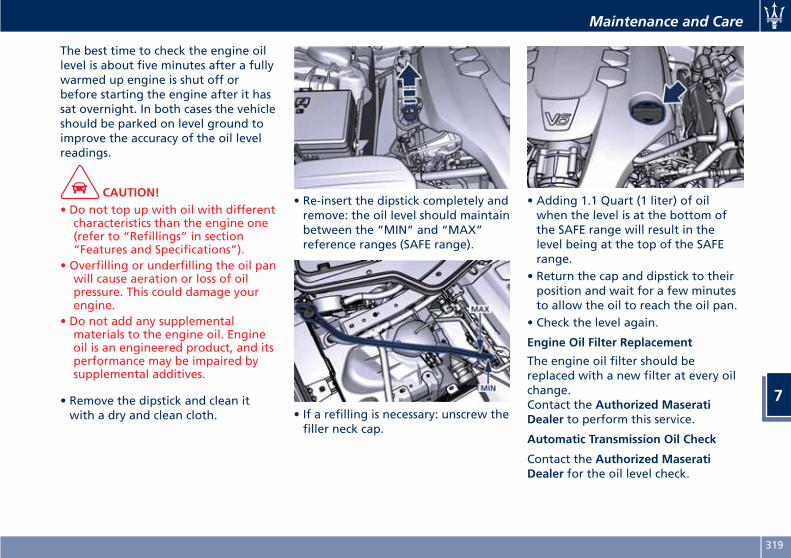
The best time to check the engine oillevel is about five minutes after a fullywarmed up engine is shut off orbefore starting the engine after it hassat overnight. In both cases the vehicleshould be parked on level ground toimprove the accuracy of the oil levelreadings.
CAUTION!• Do not top up with oil with differentcharacteristics than the engine one(refer to “Refillings” in section“Features and Specifications”).
• Overfilling or underfilling the oil panwill cause aeration or loss of oilpressure. This could damage yourengine.
• Do not add any supplementalmaterials to the engine oil. Engineoil is an engineered product, and itsperformance may be impaired bysupplemental additives.
• Remove the dipstick and clean itwith a dry and clean cloth.
• Re-insert the dipstick completely andremove: the oil level should maintainbetween the “MIN” and “MAX”reference ranges (SAFE range).
• If a refilling is necessary: unscrew thefiller neck cap.
• Adding 1.1 Quart (1 liter) of oilwhen the level is at the bottom ofthe SAFE range will result in thelevel being at the top of the SAFErange.
• Return the cap and dipstick to theirposition and wait for a few minutesto allow the oil to reach the oil pan.
• Check the level again.
Engine Oil Filter Replacement
The engine oil filter should bereplaced with a new filter at every oilchange.Contact the Authorized MaseratiDealer to perform this service.
Automatic Transmission Oil Check
Contact the Authorized MaseratiDealer for the oil level check.
Maintenance and Care
7
319
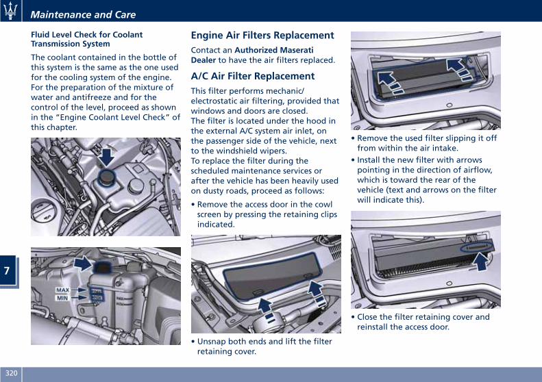
Fluid Level Check for CoolantTransmission System
The coolant contained in the bottle ofthis system is the same as the one usedfor the cooling system of the engine.For the preparation of the mixture ofwater and antifreeze and for thecontrol of the level, proceed as shownin the “Engine Coolant Level Check” ofthis chapter.
Engine Air Filters ReplacementContact an Authorized MaseratiDealer to have the air filters replaced.
A/C Air Filter ReplacementThis filter performs mechanic/electrostatic air filtering, provided thatwindows and doors are closed.The filter is located under the hood inthe external A/C system air inlet, onthe passenger side of the vehicle, nextto the windshield wipers.To replace the filter during thescheduled maintenance services orafter the vehicle has been heavily usedon dusty roads, proceed as follows:
• Remove the access door in the cowlscreen by pressing the retaining clipsindicated.
• Unsnap both ends and lift the filterretaining cover.
• Remove the used filter slipping it offfrom within the air intake.
• Install the new filter with arrowspointing in the direction of airflow,which is toward the rear of thevehicle (text and arrows on the filterwill indicate this).
• Close the filter retaining cover andreinstall the access door.
Maintenance and Care
7
320
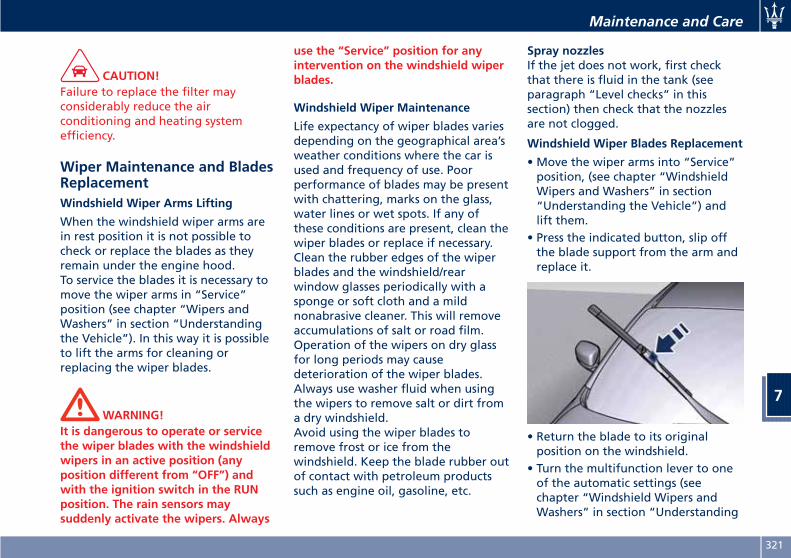
CAUTION!Failure to replace the filter mayconsiderably reduce the airconditioning and heating systemefficiency.
Wiper Maintenance and BladesReplacementWindshield Wiper Arms Lifting
When the windshield wiper arms arein rest position it is not possible tocheck or replace the blades as theyremain under the engine hood.To service the blades it is necessary tomove the wiper arms in “Service”position (see chapter “Wipers andWashers” in section “Understandingthe Vehicle”). In this way it is possibleto lift the arms for cleaning orreplacing the wiper blades.
WARNING!It is dangerous to operate or servicethe wiper blades with the windshieldwipers in an active position (anyposition different from “OFF”) andwith the ignition switch in the RUNposition. The rain sensors maysuddenly activate the wipers. Always
use the “Service” position for anyintervention on the windshield wiperblades.
Windshield Wiper Maintenance
Life expectancy of wiper blades variesdepending on the geographical area’sweather conditions where the car isused and frequency of use. Poorperformance of blades may be presentwith chattering, marks on the glass,water lines or wet spots. If any ofthese conditions are present, clean thewiper blades or replace if necessary.Clean the rubber edges of the wiperblades and the windshield/rearwindow glasses periodically with asponge or soft cloth and a mildnonabrasive cleaner. This will removeaccumulations of salt or road film.Operation of the wipers on dry glassfor long periods may causedeterioration of the wiper blades.Always use washer fluid when usingthe wipers to remove salt or dirt froma dry windshield.Avoid using the wiper blades toremove frost or ice from thewindshield. Keep the blade rubber outof contact with petroleum productssuch as engine oil, gasoline, etc.
Spray nozzlesIf the jet does not work, first checkthat there is fluid in the tank (seeparagraph “Level checks” in thissection) then check that the nozzlesare not clogged.
Windshield Wiper Blades Replacement
• Move the wiper arms into “Service”position, (see chapter “WindshieldWipers and Washers” in section“Understanding the Vehicle”) andlift them.
• Press the indicated button, slip offthe blade support from the arm andreplace it.
• Return the blade to its originalposition on the windshield.
• Turn the multifunction lever to oneof the automatic settings (seechapter “Windshield Wipers andWashers” in section “Understanding
Maintenance and Care
7
321
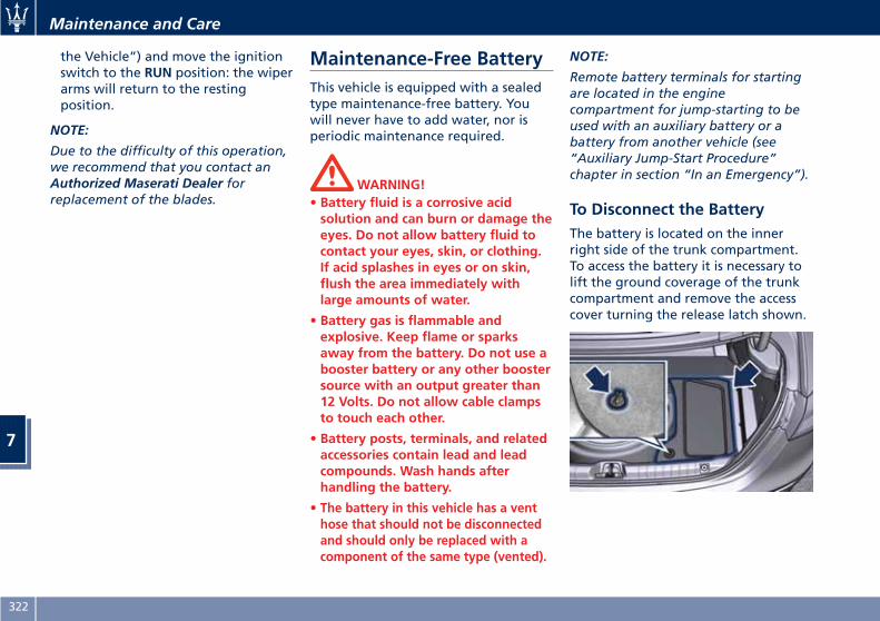
the Vehicle”) and move the ignitionswitch to the RUN position: the wiperarms will return to the restingposition.
NOTE:
Due to the difficulty of this operation,we recommend that you contact anAuthorized Maserati Dealer forreplacement of the blades.
Maintenance-Free BatteryThis vehicle is equipped with a sealedtype maintenance-free battery. Youwill never have to add water, nor isperiodic maintenance required.
WARNING!• Battery fluid is a corrosive acidsolution and can burn or damage theeyes. Do not allow battery fluid tocontact your eyes, skin, or clothing.If acid splashes in eyes or on skin,flush the area immediately withlarge amounts of water.
• Battery gas is flammable andexplosive. Keep flame or sparksaway from the battery. Do not use abooster battery or any other boostersource with an output greater than12 Volts. Do not allow cable clampsto touch each other.
• Battery posts, terminals, and relatedaccessories contain lead and leadcompounds. Wash hands afterhandling the battery.
• The battery in this vehicle has a venthose that should not be disconnectedand should only be replaced with acomponent of the same type (vented).
NOTE:
Remote battery terminals for startingare located in the enginecompartment for jump-starting to beused with an auxiliary battery or abattery from another vehicle (see“Auxiliary Jump-Start Procedure”chapter in section “In an Emergency”).
To Disconnect the BatteryThe battery is located on the innerright side of the trunk compartment.To access the battery it is necessary tolift the ground coverage of the trunkcompartment and remove the accesscover turning the release latch shown.
Maintenance and Care
7
322
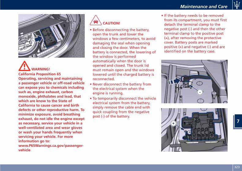
WARNING!California Proposition 65Operating, servicing and maintaininga passenger vehicle or off-road vehiclecan expose you to chemicals includingsuch as, engine exhaust, carbonmonoxide, phthalates and lead, thatwhich are know to the State ofCalifornia to cause cancer and birthdefects or other reproductive harm. Tominimize exposure, avoid breathingexhaust, do not idle the engine exceptas necessary, service your vehicle in awell-ventilated area and wear glovesor wash your hands frequently whenservicing your vehicle. For moreinformation go to:www.P65Warnings.ca.gov/passenger-vehicle
CAUTION!
• Before disconnecting the battery,open the trunk and lower thewindows a few centimeters, to avoiddamaging the seal when openingand closing the door. When thebattery is connected, the lowering ofthe window is performedautomatically when the door isopened and closed. The trunk lidmust remain open and the windowslowered until the charged battery isreconnected.
• Never disconnect the battery fromthe electrical system when theengine is running.
• To temporarily disconnect the vehicleelectrical system from the battery,simply remove the cable end withquick coupling from the negativepost (-) of the battery.
• If the battery needs to be removedfrom its compartment, you must firstdetach the terminal clamp to thenegative post (-) and then the otherterminal clamp to the positive post(+), after removing the protectivecover. Battery posts are markedpositive (+) and negative (-) and areidentified on the battery case.
Maintenance and Care
7
323
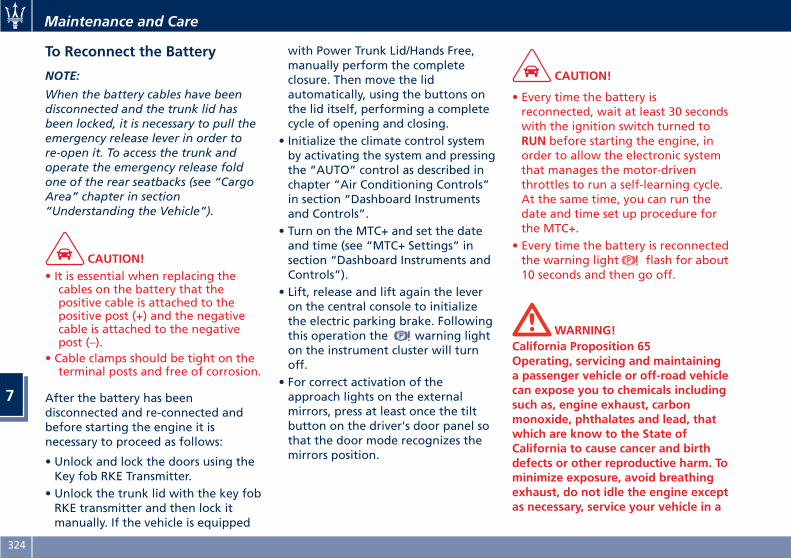
To Reconnect the Battery
NOTE:
When the battery cables have beendisconnected and the trunk lid hasbeen locked, it is necessary to pull theemergency release lever in order tore-open it. To access the trunk andoperate the emergency release foldone of the rear seatbacks (see “CargoArea” chapter in section“Understanding the Vehicle”).
CAUTION!• It is essential when replacing thecables on the battery that thepositive cable is attached to thepositive post (+) and the negativecable is attached to the negativepost (–).
• Cable clamps should be tight on theterminal posts and free of corrosion.
After the battery has beendisconnected and re-connected andbefore starting the engine it isnecessary to proceed as follows:
• Unlock and lock the doors using theKey fob RKE Transmitter.
• Unlock the trunk lid with the key fobRKE transmitter and then lock itmanually. If the vehicle is equipped
with Power Trunk Lid/Hands Free,manually perform the completeclosure. Then move the lidautomatically, using the buttons onthe lid itself, performing a completecycle of opening and closing.
• Initialize the climate control systemby activating the system and pressingthe “AUTO” control as described inchapter “Air Conditioning Controls”in section “Dashboard Instrumentsand Controls”.
• Turn on the MTC+ and set the dateand time (see “MTC+ Settings” insection “Dashboard Instruments andControls”).
• Lift, release and lift again the leveron the central console to initializethe electric parking brake. Followingthis operation the warning lighton the instrument cluster will turnoff.
• For correct activation of theapproach lights on the externalmirrors, press at least once the tiltbutton on the driver's door panel sothat the door mode recognizes themirrors position.
CAUTION!
• Every time the battery isreconnected, wait at least 30 secondswith the ignition switch turned toRUN before starting the engine, inorder to allow the electronic systemthat manages the motor-driventhrottles to run a self-learning cycle.At the same time, you can run thedate and time set up procedure forthe MTC+.
• Every time the battery is reconnectedthe warning light flash for about10 seconds and then go off.
WARNING!California Proposition 65Operating, servicing and maintaininga passenger vehicle or off-road vehiclecan expose you to chemicals includingsuch as, engine exhaust, carbonmonoxide, phthalates and lead, thatwhich are know to the State ofCalifornia to cause cancer and birthdefects or other reproductive harm. Tominimize exposure, avoid breathingexhaust, do not idle the engine exceptas necessary, service your vehicle in a
Maintenance and Care
7
324
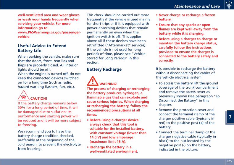
well-ventilated area and wear glovesor wash your hands frequently whenservicing your vehicle. For moreinformation go to:www.P65Warnings.ca.gov/passenger-vehicle
Useful Advice to ExtendBattery LifeWhen parking the vehicle, make surethat the doors, front, rear lids andflaps are properly closed. All interiorlights should be off.When the engine is turned off, do notkeep the connected devices switchedon for a long time (such as radio,hazard warning flashers, fan, etc.).
CAUTION!If the battery charge remains below50% for a long period of time, it willbe damaged due to sulfation; itsperformance and starting power willbe reduced and it will be more subjectto freezing.
We recommend you to have thebattery charge condition checked,preferably at the beginning of thecold season, to prevent the electrolytefrom freezing.
This check should be carried out morefrequently if the vehicle is used mainlyfor short trips or if it is equipped withpower-absorbing devices that remainpermanently on even when theignition switch is off. This appliesabove all if these devices have beenretrofitted ("Aftermarket" services).If the vehicle is not used for longperiods of time, please see “VehicleStored for Long Periods” in thissection.
Battery Recharge
WARNING!The process of charging or rechargingthe battery produces hydrogen, aflammable gas that can explode andcause serious injuries. When chargingor recharging the battery, follow therecommended precautions at alltimes.
• Before using a charger devicealways check that this tool issuitable for the installed battery,with constant voltage (lower than14.0 V) and low amperage(maximum limit 15 A).
• Recharge the battery in awell-ventilated environment.
• Never charge or recharge a frozenbattery.
• Ensure that any sparks or openflames are kept well away from thebattery while it is charging.
• Before using a charger to charge ormaintain the battery charge status,carefully follow the instructionsprovided to ensure the charger isconnected to the battery safely andcorrectly.
It is possible to recharge the batterywithout disconnecting the cables ofthe vehicle electrical system.
• To access the battery lift the groundcoverage of the trunk compartmentand remove the access cover aspreviously shown (see paragraph “ToDisconnect the Battery" in thischapter.
• Remove the protection cover andconnect the terminal clamp of thecharger positive cable (typically inred) to the positive post (+) of thebattery.
• Connect the terminal clamp of thecharger negative cable (typically inblack) to the nut located by thenegative post (-) on the battery,indicated in the picture.
Maintenance and Care
7
325
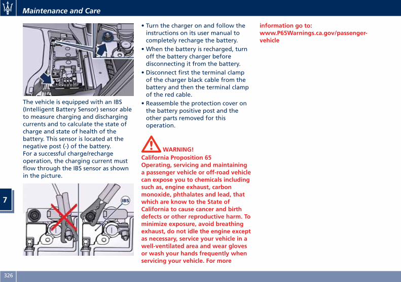
The vehicle is equipped with an IBS(Intelligent Battery Sensor) sensor ableto measure charging and dischargingcurrents and to calculate the state ofcharge and state of health of thebattery. This sensor is located at thenegative post (-) of the battery.For a successful charge/rechargeoperation, the charging current mustflow through the IBS sensor as shownin the picture.
• Turn the charger on and follow theinstructions on its user manual tocompletely recharge the battery.
• When the battery is recharged, turnoff the battery charger beforedisconnecting it from the battery.
• Disconnect first the terminal clampof the charger black cable from thebattery and then the terminal clampof the red cable.
• Reassemble the protection cover onthe battery positive post and theother parts removed for thisoperation.
WARNING!California Proposition 65Operating, servicing and maintaininga passenger vehicle or off-road vehiclecan expose you to chemicals includingsuch as, engine exhaust, carbonmonoxide, phthalates and lead, thatwhich are know to the State ofCalifornia to cause cancer and birthdefects or other reproductive harm. Tominimize exposure, avoid breathingexhaust, do not idle the engine exceptas necessary, service your vehicle in awell-ventilated area and wear glovesor wash your hands frequently whenservicing your vehicle. For more
information go to:www.P65Warnings.ca.gov/passenger-vehicle
Maintenance and Care
7
326
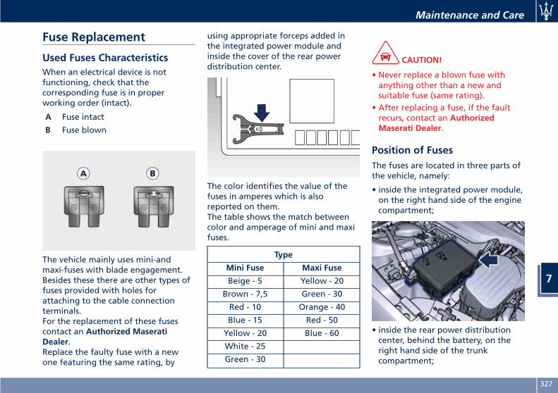
Fuse Replacement
Used Fuses CharacteristicsWhen an electrical device is notfunctioning, check that thecorresponding fuse is in properworking order (intact).
A Fuse intact
B Fuse blown
The vehicle mainly uses mini-andmaxi-fuses with blade engagement.Besides these there are other types offuses provided with holes forattaching to the cable connectionterminals.For the replacement of these fusescontact an Authorized MaseratiDealer.Replace the faulty fuse with a newone featuring the same rating, by
using appropriate forceps added inthe integrated power module andinside the cover of the rear powerdistribution center.
The color identifies the value of thefuses in amperes which is alsoreported on them.The table shows the match betweencolor and amperage of mini and maxifuses.
Type
Mini Fuse Maxi Fuse
Beige - 5 Yellow - 20
Brown - 7,5 Green - 30
Red - 10 Orange - 40
Blue - 15 Red - 50
Yellow - 20 Blue - 60
White - 25
Green - 30
CAUTION!
• Never replace a blown fuse withanything other than a new andsuitable fuse (same rating).
• After replacing a fuse, if the faultrecurs, contact an AuthorizedMaserati Dealer.
Position of FusesThe fuses are located in three parts ofthe vehicle, namely:
• inside the integrated power module,on the right hand side of the enginecompartment;
• inside the rear power distributioncenter, behind the battery, on theright hand side of the trunkcompartment;
Maintenance and Care
7
327
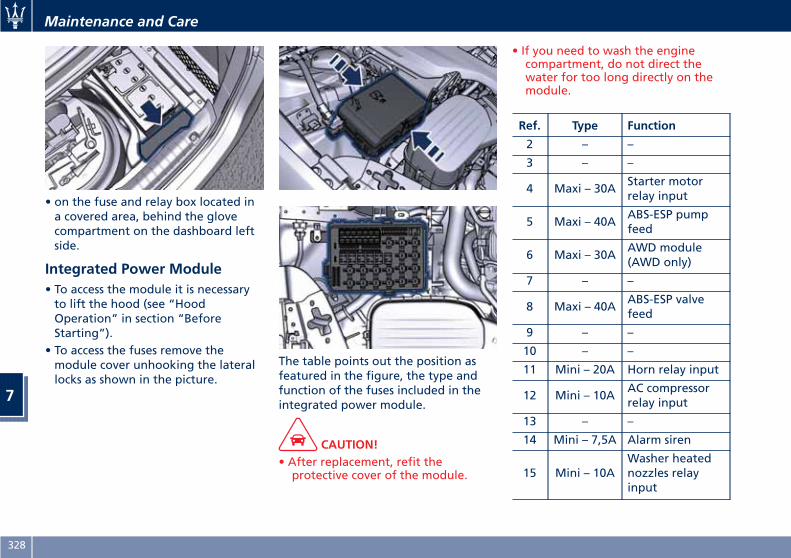
• on the fuse and relay box located ina covered area, behind the glovecompartment on the dashboard leftside.
Integrated Power Module• To access the module it is necessaryto lift the hood (see “HoodOperation” in section “BeforeStarting”).
• To access the fuses remove themodule cover unhooking the laterallocks as shown in the picture.
The table points out the position asfeatured in the figure, the type andfunction of the fuses included in theintegrated power module.
CAUTION!• After replacement, refit theprotective cover of the module.
• If you need to wash the enginecompartment, do not direct thewater for too long directly on themodule.
Ref. Type Function
2 – –
3 – –
4 Maxi – 30AStarter motorrelay input
5 Maxi – 40AABS-ESP pumpfeed
6 Maxi – 30AAWD module(AWD only)
7 – –
8 Maxi – 40AABS-ESP valvefeed
9 – –
10 – –
11 Mini – 20A Horn relay input
12 Mini – 10AAC compressorrelay input
13 – –
14 Mini – 7,5A Alarm siren
15 Mini – 10AWasher heatednozzles relayinput
Maintenance and Care
7
328
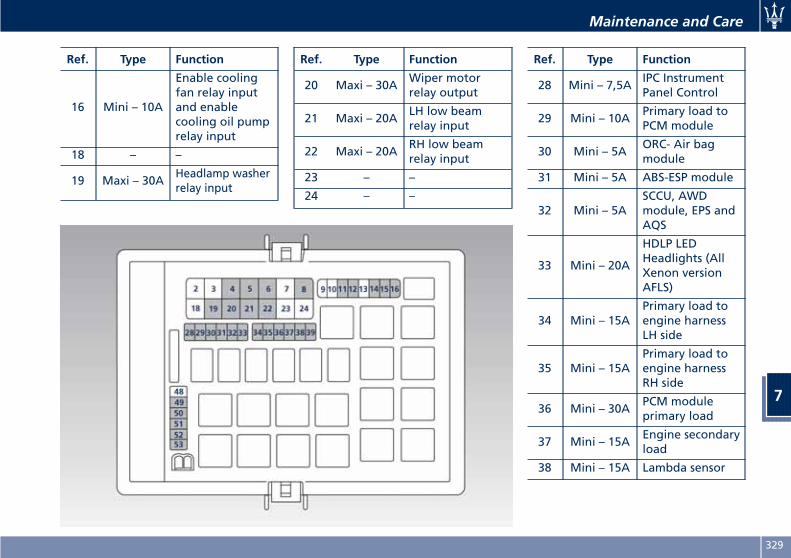
Ref. Type Function
16 Mini – 10A
Enable coolingfan relay inputand enablecooling oil pumprelay input
18 – –
19 Maxi – 30AHeadlamp washerrelay input
Ref. Type Function
20 Maxi – 30AWiper motorrelay output
21 Maxi – 20ALH low beamrelay input
22 Maxi – 20ARH low beamrelay input
23 – –
24 – –
Ref. Type Function
28 Mini – 7,5AIPC InstrumentPanel Control
29 Mini – 10APrimary load toPCM module
30 Mini – 5AORC- Air bagmodule
31 Mini – 5A ABS-ESP module
32 Mini – 5ASCCU, AWDmodule, EPS andAQS
33 Mini – 20A
HDLP LEDHeadlights (AllXenon versionAFLS)
34 Mini – 15APrimary load toengine harnessLH side
35 Mini – 15APrimary load toengine harnessRH side
36 Mini – 30APCM moduleprimary load
37 Mini – 15AEngine secondaryload
38 Mini – 15A Lambda sensor
Maintenance and Care
7
329
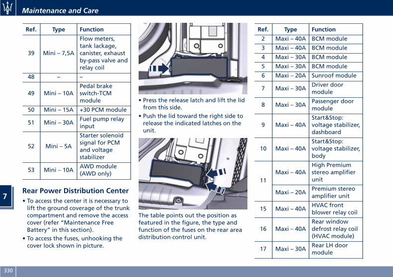
Ref. Type Function
39 Mini – 7,5A
Flow meters,tank lackage,canister, exhaustby-pass valve andrelay coil
48 – –
49 Mini – 10APedal brakeswitch-TCMmodule
50 Mini – 15A +30 PCM module
51 Mini – 30AFuel pump relayinput
52 Mini – 5A
Starter solenoidsignal for PCMand voltagestabilizer
53 Mini – 10AAWD module(AWD only)
Rear Power Distribution Center• To access the center it is necessary tolift the ground coverage of the trunkcompartment and remove the accesscover (refer “Maintenance FreeBattery” in this section).
• To access the fuses, unhooking thecover lock shown in picture.
• Press the release latch and lift the lidfrom this side.
• Push the lid toward the right side torelease the indicated latches on theunit.
The table points out the position asfeatured in the figure, the type andfunction of the fuses on the rear areadistribution control unit.
Ref. Type Function
2 Maxi – 40A BCM module
3 Maxi – 40A BCM module
4 Maxi – 30A BCM module
5 Maxi – 30A BCM module
6 Maxi – 20A Sunroof module
7 Maxi – 30ADriver doormodule
8 Maxi – 30APassenger doormodule
9 Maxi – 40AStart&Stop:voltage stabilizer,dashboard
10 Maxi – 40AStart&Stop:voltage stabilizer,body
11Maxi – 40A
High Premiumstereo amplifierunit
Maxi – 20APremium stereoamplifier unit
15 Maxi – 40AHVAC frontblower relay coil
16 Maxi – 40ARear windowdefrost relay coil(HVAC module)
17 Maxi – 30ARear LH doormodule
Maintenance and Care
7
330
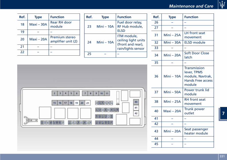
Ref. Type Function
18 Maxi – 30ARear RH doormodule
19 – –
20 Maxi – 20APremium stereoamplifier unit (2)
21 – –
22 – –
Ref. Type Function
23 Mini – 10AFuel door relay,RF Hub module,ELSD
24 Mini – 10A
ITM module,ceiling light units(front and rear),rain/lights sensor
25 – –
Ref. Type Function
26 – –
27 – –
31 Mini – 25ALH front seatmovement
32 Mini – 30A ELSD module
33 – –
34 Mini – 20ASoft Door Closelatch
35 – –
36 Mini – 10A
Transmissionlever, TPMSmodule, Navtrak,Hands Free accessmodule
37 Mini – 50APower trunk lidmodule
38 Mini – 25ARH front seatmovement
40 Maxi – 20ATrunk poweroutlet
41 – –
42 – –
43 Mini – 20ASeat passengerheater module
44 – –
45 – –
Maintenance and Care
7
331
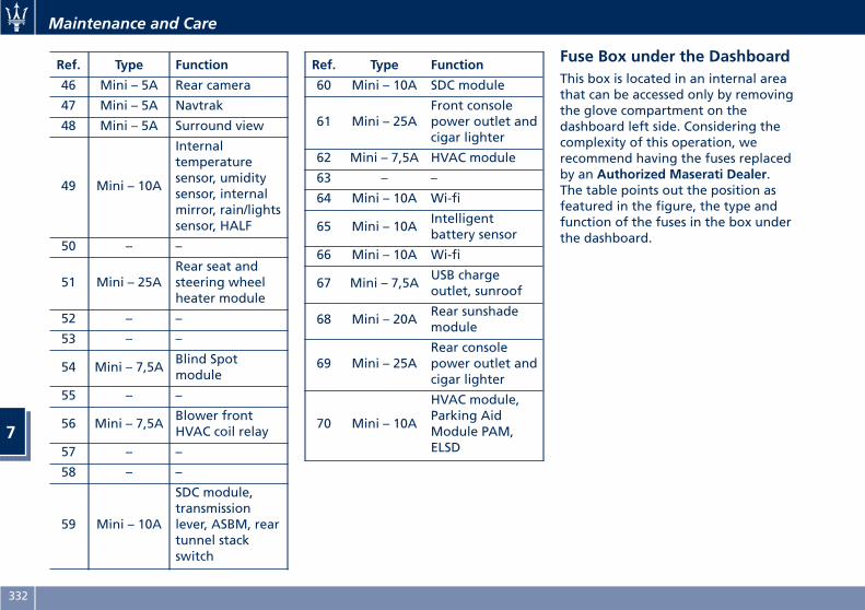
Ref. Type Function
46 Mini – 5A Rear camera
47 Mini – 5A Navtrak
48 Mini – 5A Surround view
49 Mini – 10A
Internaltemperaturesensor, umiditysensor, internalmirror, rain/lightssensor, HALF
50 – –
51 Mini – 25ARear seat andsteering wheelheater module
52 – –
53 – –
54 Mini – 7,5ABlind Spotmodule
55 – –
56 Mini – 7,5ABlower frontHVAC coil relay
57 – –
58 – –
59 Mini – 10A
SDC module,transmissionlever, ASBM, reartunnel stackswitch
Ref. Type Function
60 Mini – 10A SDC module
61 Mini – 25AFront consolepower outlet andcigar lighter
62 Mini – 7,5A HVAC module
63 – –
64 Mini – 10A Wi-fi
65 Mini – 10AIntelligentbattery sensor
66 Mini – 10A Wi-fi
67 Mini – 7,5AUSB chargeoutlet, sunroof
68 Mini – 20ARear sunshademodule
69 Mini – 25ARear consolepower outlet andcigar lighter
70 Mini – 10A
HVAC module,Parking AidModule PAM,ELSD
Fuse Box under the DashboardThis box is located in an internal areathat can be accessed only by removingthe glove compartment on thedashboard left side. Considering thecomplexity of this operation, werecommend having the fuses replacedby an Authorized Maserati Dealer.The table points out the position asfeatured in the figure, the type andfunction of the fuses in the box underthe dashboard.
Maintenance and Care
7
332
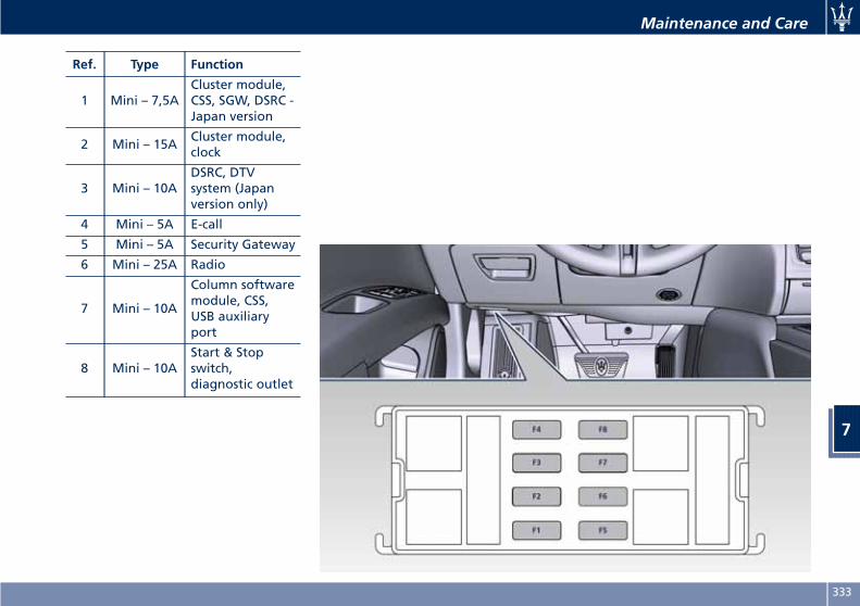
Ref. Type Function
1 Mini – 7,5ACluster module,CSS, SGW, DSRC -Japan version
2 Mini – 15ACluster module,clock
3 Mini – 10ADSRC, DTVsystem (Japanversion only)
4 Mini – 5A E-call
5 Mini – 5A Security Gateway
6 Mini – 25A Radio
7 Mini – 10A
Column softwaremodule, CSS,USB auxiliaryport
8 Mini – 10AStart & Stopswitch,diagnostic outlet
Maintenance and Care
7
333
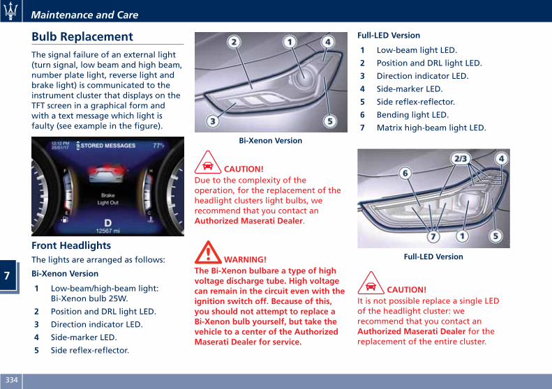
Bulb ReplacementThe signal failure of an external light(turn signal, low beam and high beam,number plate light, reverse light andbrake light) is communicated to theinstrument cluster that displays on theTFT screen in a graphical form andwith a text message which light isfaulty (see example in the figure).
Front HeadlightsThe lights are arranged as follows:
Bi-Xenon Version
1 Low-beam/high-beam light:Bi-Xenon bulb 25W.
2 Position and DRL light LED.
3 Direction indicator LED.
4 Side-marker LED.
5 Side reflex-reflector.
CAUTION!Due to the complexity of theoperation, for the replacement of theheadlight clusters light bulbs, werecommend that you contact anAuthorized Maserati Dealer.
WARNING!The Bi-Xenon bulbare a type of highvoltage discharge tube. High voltagecan remain in the circuit even with theignition switch off. Because of this,you should not attempt to replace aBi-Xenon bulb yourself, but take thevehicle to a center of the AuthorizedMaserati Dealer for service.
Full-LED Version
1 Low-beam light LED.
2 Position and DRL light LED.
3 Direction indicator LED.
4 Side-marker LED.
5 Side reflex-reflector.
6 Bending light LED.
7 Matrix high-beam light LED.
CAUTION!It is not possible replace a single LEDof the headlight cluster: werecommend that you contact anAuthorized Maserati Dealer for thereplacement of the entire cluster.
Bi-Xenon Version
Full-LED Version
Maintenance and Care
7
334
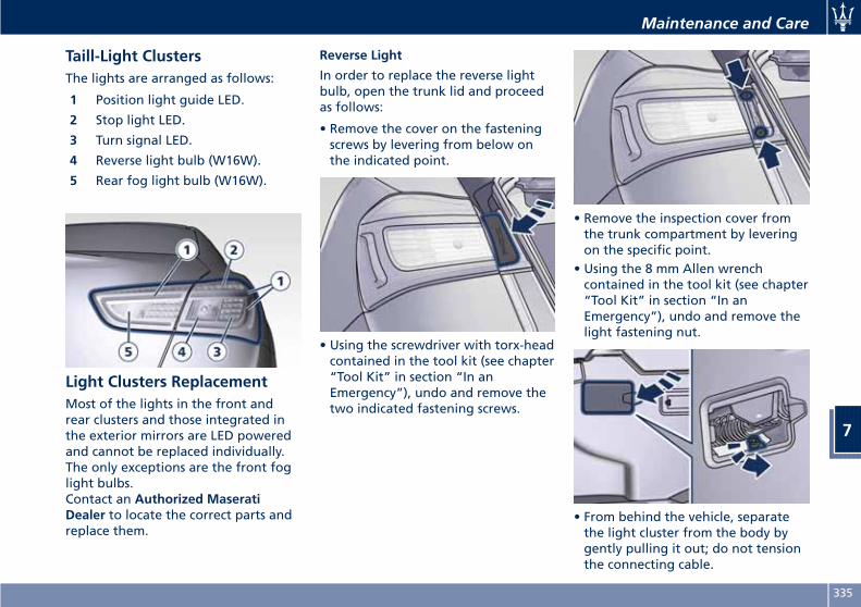
Taill-Light ClustersThe lights are arranged as follows:
1 Position light guide LED.
2 Stop light LED.
3 Turn signal LED.
4 Reverse light bulb (W16W).
5 Rear fog light bulb (W16W).
Light Clusters ReplacementMost of the lights in the front andrear clusters and those integrated inthe exterior mirrors are LED poweredand cannot be replaced individually.The only exceptions are the front foglight bulbs.Contact an Authorized MaseratiDealer to locate the correct parts andreplace them.
Reverse Light
In order to replace the reverse lightbulb, open the trunk lid and proceedas follows:
• Remove the cover on the fasteningscrews by levering from below onthe indicated point.
• Using the screwdriver with torx-headcontained in the tool kit (see chapter“Tool Kit” in section “In anEmergency”), undo and remove thetwo indicated fastening screws.
• Remove the inspection cover fromthe trunk compartment by leveringon the specific point.
• Using the 8 mm Allen wrenchcontained in the tool kit (see chapter“Tool Kit” in section “In anEmergency”), undo and remove thelight fastening nut.
• From behind the vehicle, separatethe light cluster from the body bygently pulling it out; do not tensionthe connecting cable.
Maintenance and Care
7
335
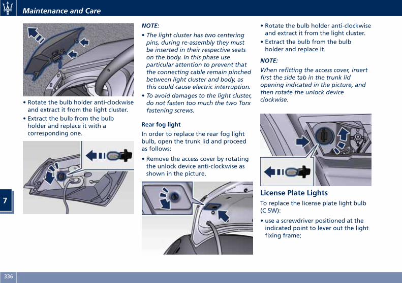
• Rotate the bulb holder anti-clockwiseand extract it from the light cluster.
• Extract the bulb from the bulbholder and replace it with acorresponding one.
NOTE:
• The light cluster has two centeringpins, during re-assembly they mustbe inserted in their respective seatson the body. In this phase useparticular attention to prevent thatthe connecting cable remain pinchedbetween light cluster and body, asthis could cause electric interruption.
• To avoid damages to the light cluster,do not fasten too much the two Torxfastening screws.
Rear fog light
In order to replace the rear fog lightbulb, open the trunk lid and proceedas follows:
• Remove the access cover by rotatingthe unlock device anti-clockwise asshown in the picture.
• Rotate the bulb holder anti-clockwiseand extract it from the light cluster.
• Extract the bulb from the bulbholder and replace it.
NOTE:
When refitting the access cover, insertfirst the side tab in the trunk lidopening indicated in the picture, andthen rotate the unlock deviceclockwise.
License Plate LightsTo replace the license plate light bulb(C 5W):
• use a screwdriver positioned at theindicated point to lever out the lightfixing frame;
Maintenance and Care
7
336
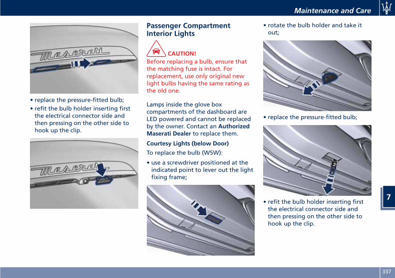
• replace the pressure-fitted bulb;• refit the bulb holder inserting firstthe electrical connector side andthen pressing on the other side tohook up the clip.
Passenger CompartmentInterior Lights
CAUTION!Before replacing a bulb, ensure thatthe matching fuse is intact. Forreplacement, use only original newlight bulbs having the same rating asthe old one.
Lamps inside the glove boxcompartments of the dashboard areLED powered and cannot be replacedby the owner. Contact an AuthorizedMaserati Dealer to replace them.
Courtesy Lights (below Door)
To replace the bulb (W5W):
• use a screwdriver positioned at theindicated point to lever out the lightfixing frame;
• rotate the bulb holder and take itout;
• replace the pressure-fitted bulb;
• refit the bulb holder inserting firstthe electrical connector side andthen pressing on the other side tohook up the clip.
Maintenance and Care
7
337
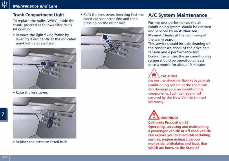
Trunk Compartment LightTo replace the bulbs (W5W) inside thetrunk, proceed as follows after trunklid opening.
• Remove the light fixing frame bylevering it out gently at the indicatedpoint with a screwdriver.
• Raise the lens cover.
• Replace the pressure-fitted bulb.
• Refit the lens cover, inserting first theelectrical connector side and thenpressing on the other side.
A/C System MaintenanceFor the best performance, the airconditioning system should be checkedand serviced by an AuthorizedMaserati Dealer at the beginning ofthe warm season.This service should include cleaning ofthe condenser, check of the drive belttension and a performance test.During the winter, the air conditioningsystem should be operated at leastonce a month for about 10 minutes.
CAUTION!Do not use chemical flushes in your airconditioning system as the chemicalscan damage your air conditioningcomponents. Such damage is notcovered by the New Vehicle LimitedWarranty.
WARNING!California Proposition 65Operating, servicing and maintaininga passenger vehicle or off-road vehiclecan expose you to chemicals includingsuch as, engine exhaust, carbonmonoxide, phthalates and lead, thatwhich are know to the State of
Maintenance and Care
7
338
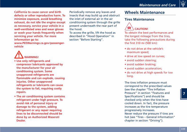
California to cause cancer and birthdefects or other reproductive harm. Tominimize exposure, avoid breathingexhaust, do not idle the engine exceptas necessary, service your vehicle in awell-ventilated area and wear glovesor wash your hands frequently whenservicing your vehicle. For moreinformation go to:www.P65Warnings.ca.gov/passenger-vehicle
WARNING!• Use only refrigerants andcompressor lubricants approved bythe manufacturer for your airconditioning system. Someunapproved refrigerants areflammable and can explode, causinginjuries. Other unapprovedrefrigerants or lubricants can causethe system to fail, requiring costlyrepairs.
• The air conditioning system containsrefrigerant under high pressure. Toavoid risk of personal injury ordamage to the system, addingrefrigerant or any repair requiringlines to be disconnected should bedone by an Authorized MaseratiDealer.
Periodically remove any leaves andinsects that may build up and obstructthe inlet of external air in the airconditioning system through the grillepresent underneath the rear part ofthe hood.To access the grille, lift the hood asdescribed in “Hood Operation” insection “Before Starting”.
Wheels Maintenance
Tires Maintenance
CAUTION!To obtain the best performances andthe longest mileage from the tires,take the following precautions duringthe first 310 mi (500 km):
• do not drive at the vehicle’smaximum speed;
• drive at low speed on curves;• avoid sudden steering;• avoid sudden braking;• avoid sudden acceleration;• do not drive at high speeds for toolong.
The tires inflation pressure mustcorrespond to the prescribed values(see the chapter “Tire InflationPressure” in section “Features andSpecifications”) and should bechecked only when the tires havecooled down. In fact, the pressureincreases as the tire temperatureprogressively increases.Never reduce the pressure if tires arehot (see “Tires – General Information”chapter in section “Driving”).
Maintenance and Care
7
339
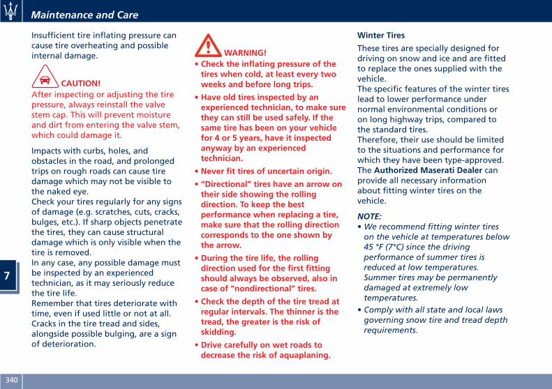
Insufficient tire inflating pressure cancause tire overheating and possibleinternal damage.
CAUTION!After inspecting or adjusting the tirepressure, always reinstall the valvestem cap. This will prevent moistureand dirt from entering the valve stem,which could damage it.
Impacts with curbs, holes, andobstacles in the road, and prolongedtrips on rough roads can cause tiredamage which may not be visible tothe naked eye.Check your tires regularly for any signsof damage (e.g. scratches, cuts, cracks,bulges, etc.). If sharp objects penetratethe tires, they can cause structuraldamage which is only visible when thetire is removed.In any case, any possible damage mustbe inspected by an experiencedtechnician, as it may seriously reducethe tire life.Remember that tires deteriorate withtime, even if used little or not at all.Cracks in the tire tread and sides,alongside possible bulging, are a signof deterioration.
WARNING!• Check the inflating pressure of thetires when cold, at least every twoweeks and before long trips.
• Have old tires inspected by anexperienced technician, to make surethey can still be used safely. If thesame tire has been on your vehiclefor 4 or 5 years, have it inspectedanyway by an experiencedtechnician.
• Never fit tires of uncertain origin.
• “Directional” tires have an arrow ontheir side showing the rollingdirection. To keep the bestperformance when replacing a tire,make sure that the rolling directioncorresponds to the one shown bythe arrow.
• During the tire life, the rollingdirection used for the first fittingshould always be observed, also incase of “nondirectional” tires.
• Check the depth of the tire tread atregular intervals. The thinner is thetread, the greater is the risk ofskidding.
• Drive carefully on wet roads todecrease the risk of aquaplaning.
Winter Tires
These tires are specially designed fordriving on snow and ice and are fittedto replace the ones supplied with thevehicle.The specific features of the winter tireslead to lower performance undernormal environmental conditions oron long highway trips, compared tothe standard tires.Therefore, their use should be limitedto the situations and performance forwhich they have been type-approved.The Authorized Maserati Dealer canprovide all necessary informationabout fitting winter tires on thevehicle.
NOTE:•We recommend fitting winter tireson the vehicle at temperatures below45 °F (7°C) since the drivingperformance of summer tires isreduced at low temperatures.Summer tires may be permanentlydamaged at extremely lowtemperatures.
• Comply with all state and local lawsgoverning snow tire and tread depthrequirements.
Maintenance and Care
7
340
Wheel Rims MaintenanceAll wheel trims should be cleanedregularly with a mild soap and water.To remove heavy soil and/or excessivebrake dust, use a nonabrasive,non-acidic cleaner.Do not use scouring pads, steel wool,a bristle brush, or metal polishes.Do not use oven cleaner that mayaffect and damage the brake calipers.Avoid automatic car washes that useacidic solutions or harsh brushes thatmay damage the wheel rim protectivefinish.
Bodywork Maintenanceand Care
Protection from AtmosphericAgentsThe main causes of corrosion are:
• atmospheric pollution;• salinity and humidity in theatmosphere (marine areas or a dampclimate);
• seasonal environmental conditions;• salt scattered on the roadbed tomelt ice and snow.
The abrasive action of wind-carriedatmospheric dust and sand, mud andstones should not be underestimated.On this vehicle, Maserati has adoptedthe best technological solutions toprotect the bodywork from corrosion.The main measures are:
• paint products and systems that givethe vehicle particular resistance tocorrosion and abrasion;
• use of galvanized (or pre-treated)metal sheets which are highlyresistant to corrosion in the mostexposed parts;
• spraying of the underbody, enginecompartment, insides of wheelhousings, and other structures with
wax products having high protectivepower;
• spraying of plastic materials, with aprotective function, in the mostexposed points: underneath thedoors, inside part of the mud guards,edges, etc.;
• use of ventilated box sections,coated with protective wax products,to avoid condensation and trappedwater which could encourage theformation of internal rust.
Useful Advice to Keep theBodywork in Good ConditionPaint
The paintwork does not only have anaesthetic function but also protectsthe underlying metal sheets. In theevent of abrasions or deep scratches,we recommend to have the necessarytouch-ups made immediately, to avoidany rust formation. Touch-ups do notfeature particular difficulties, even onmetallic finishes.For all paint touch-ups, use onlyoriginal products indicated on theplate applied on the lower left side ofthe hood.
Maintenance and Care
7
341
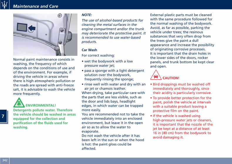
Normal paint maintenance consists inwashing, the frequency of whichdepends on the conditions of use andof the environment. For example, ifdriving the vehicle in areas wherethere is high atmospheric pollution orthe roads are spread with anti-freezesalt, it is advisable to wash the vehiclemore frequently.
ENVIRONMENTAL!Detergents pollute water. Thereforethe vehicle should be washed in areasequipped for the collection andpurification of the fluids used forwashing.
NOTE:
The use of alcohol-based products forcleaning the metal surfaces in theengine compartment and/or the trunkmay deteriorate the protective paint. Itis recommended to use water-basedproducts.
Car Wash
For correct washing:
• wet the bodywork with a lowpressure water jet;
• pass a sponge with a light detergentsolution over the bodywork,frequently rinsing the sponge;
• rinse well with water and dry with anair jet or chamois leather.
When drying, take particular care withthe parts that are less visible, such asthe door and lids bays, headlightedges, in which water can be trappedmore easily.You are recommended not to take thevehicle immediately into an enclosedenvironment, but leave it in the openair so as to allow the water toevaporate.Do not wash the vehicle after it hasbeen left in the sun or when the hoodis hot: the paint gloss could beaffected.
External plastic parts must be cleanedwith the same procedure followed forthe normal washing of the bodywork.Avoid, as far as possible, parking thevehicle under trees; the resinoussubstances that very often drop fromthe trees give the paint a dullappearance and increase the possibilityof originating corrosive processes.It is important that the drain holes inthe lower sides of the doors, rockerpanels, and trunk bottom be kept clearand open.
CAUTION!
• Bird droppings must be washed offimmediately and thoroughly, sincetheir acidity is particularly corrosive.
• To provide better protection for thepaint, polish the vehicle at intervalswith a suitable product leaving aprotective film on the paint.
• If the vehicle is washed usinghigh-pressure water jets or cleaners,it is important that the nozzle of thejet be kept at a distance of at least16 in (40 cm) from the bodywork toavoid damaging it.
Maintenance and Care
7
342
Glass Surfaces
All glass surfaces should be cleaned ona regular basis with any commercialhousehold-type glass cleaner.Never use an abrasive type cleaner.Use caution when cleaning the insiderear window equipped with electricdefrosters. Do not use scrapers orother sharp instrument that mayscratch the elements.When cleaning the rearview mirror,spray cleaner on the towel or rag thatyou are using. Do not spray cleanerdirectly on the mirror.Labels can be peeled off after soakingwith warm water.When cleaning is performed, keep allmetal objects at a safe distance fromthe window.
Cleaning Headlights
Your vehicle has plastic headlights thatare lighter and less susceptible tostone breakage than glass headlights.Plastic is not as scratch-resistant asglass and therefore different lenscleaning procedures must be followed.To minimize the possibility ofscratching the lenses and reducinglight output, avoid wiping with a drycloth. To remove road dirt, wash witha mild soap solution followed byrinsing.
Do not use abrasive cleaningcomponents, solvents, steel wool orother aggressive material to clean thelenses.
Moldings and Aluminum Trims
• For cleaning moldings and aluminumtrims, avoid the use of acidic oralkaline cleaning agents that candestroy the protecting surfacetreatment.
• After washing aluminum trim withwarm water, apply the cleaningagent with a clean tissue or a softsponge on the surface. Do not useany other equipment such asbrushes, steel wool, abrasives or anyother equipment for cleaning.
• After cleaning, please rinse thealuminum trim with a lot of clearwater.
• While cleaning in the car, pleasemake sure that the moldings andaluminum trims only get in contactwith soft brushes or textiles.
Engine Compartment
At the end of each winter season,carefully wash the enginecompartment, remembering to avoiddirecting the jet of water for too longon the electric parts.
To perform this operation, you mustcontact an Authorized MaseratiDealer.
Pre-Short Drop FunctionWhen in a car wash, if the driver keepsthe RKE Transmitter in his/her pocket,or in any place outside the vehiclewithin 3.3 ft (1 m) distance, the frontwindows will perform a pre-shortdrop. This is a shorter drop comparedto the normal short drop performedby the “Passive Entry” function whenyou grab the door handle to enter thevehicle.In order to prevent water fromentering the vehicle between theupper edge of the glass window andthe door outline on the bodywork,while the car is being washed, it isadvisable to disable the “PassiveEntry” from the MTC+ System, forfurther information refer to chapter“MTC+ Settings” in section“Dashboard Instruments andcontrols”. When deactivating the“Passive Entry”, also the “Pre-ShortDrop” function will be disabled.
Maintenance and Care
7
343
Interior Maintenance andCareInterior trim should be cleanedstarting with a damp cloth. Do not useharsh cleaners.The leather upholstery can be bestpreserved by regular cleaning with adamp soft cloth. Small particles of dirtcan act as an abrasive and damage theleather upholstery and should beremoved promptly with a damp cloth.Stubborn soils stains can be removedeasily with a soft cloth andappropriate products. Avoid soakingthe leather upholstery with any liquid.Please do not use polishes, oils,cleaning fluids, solvents, detergents, orammonia-based cleaners to clean yourleather upholstery.Application of a leather conditioner isnot required to maintain the originalcondition.Check at regular intervals that there isno water trapped under the mats (dueto drips off shoes, umbrellas etc.)which may cause the metal parts tooxidize.
CAUTION!Do not use alcohol, petrol or solventsto clean the instrument cluster's
transparent dome, the MTC+ display,the analog clock and the leatherupholstery. We recommended the useof “Car Care” products approved byMaserati for the maintenance and careof the interior.
Leather Upholstery TreatmentHave the leather upholstery onlytreated, as provided in the ScheduledService Plan, by an AuthorizedMaserati Dealer which has therequired specific products.
Parts in Premium Quality WoodRemove any dirt with a damp cloth.
NOTE:
The Authorized Maserati Dealer canprovide you with any informationabout the Maserati approved “CarCare” products, available in the“Genuine Accessories” range.
WARNING!California Proposition 65Operating, servicing and maintaininga passenger vehicle or off-road vehiclecan expose you to chemicals includingsuch as, engine exhaust, carbonmonoxide, phthalates and lead, that
which are know to the State ofCalifornia to cause cancer and birthdefects or other reproductive harm. Tominimize exposure, avoid breathingexhaust, do not idle the engine exceptas necessary, service your vehicle in awell-ventilated area and wear glovesor wash your hands frequently whenservicing your vehicle. For moreinformation go to:www.P65Warnings.ca.gov/passenger-vehicle
Maintenance and Care
7
344
Vehicle Stored for LongPeriodsIf the vehicle is going to be stored forlong periods of time, follow the belowprecautions:
• Wash and dry the vehiclethoroughly.
• Store the vehicle on a level surface ina covered, dry and, if possible,ventilated area.
• Select P (Park) and turn off theengine.
• Disconnect the battery (refer“Maintenance-Free Battery” in thissection) or connect a battery charger(refer to paragraph “MaintainingBattery Charge” of chapter “BatteryStatement” in this section).
• Check the battery charge status.During parking, this check must becarried out every three weeks.Recharge the battery if the opencircuit voltage is lower than 12.2 V.
• Check that the parking brake is NOTengaged.
• Do not empty the engine coolingsystem.
• Clean and protect the painted partsapplying protective wax.
• Clean and protect polished metalparts with special products availableon the market.
• Cover the vehicle with a long clothin breathable fabric (available froman Authorized Maserati Dealer). Donot use thick plastic sheets, which donot allow the humidity on thevehicle surface to evaporate.
• Inflate the tires up to a pressurewhich must be 14.5 psi (1 bar) higherthan the normally prescribed one,and check it at regular intervals.
NOTE:
The Authorized Maserati Dealer canprovide you with any informationabout the available “Indoor andOutdoor Car Covers”, available in the“Genuine Accessories” range.
WARNING!The tire pressure must be broughtback to the prescribed value beforereusing the vehicle (see “Tire InflationPressure” in section “Features andSpecifications”).
Restarting the VehicleBefore restarting the vehicle after along period of inactivity, werecommend that you carry out thefollowing operations.
• Check the tires for pressure and forany damages, cuts or cracks. If this isthe case, have them replaced.
• Do not dry-rub the external surfaceof the vehicle: use a damp cloth.
• Visually inspect if there are any fluidleaks (oil, brake and clutch fluid,engine coolant etc.).
• Have the engine oil and filterreplaced.
• Check the fluid levels in the brakesystem, as well as the engine coolantlevel.
• Check the air filters and have themreplaced if necessary.
• Reconnect the battery after checkingthe charge status (refer to“Maintenance-Free Battery” in thissection) and perform the initializingprocedure if applicable. You canconsult the paragraph “BatteryReconnection” in this chapter forfurther information on this subject.
Maintenance and Care
7
345
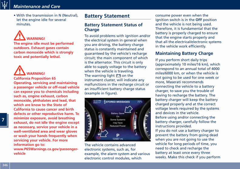
• With the transmission in N (Neutral),let the engine idle for severalminutes.
WARNING!The engine idle must be performedoutdoors. Exhaust gases containcarbon monoxide which is stronglytoxic and potentially lethal.
WARNING!California Proposition 65Operating, servicing and maintaininga passenger vehicle or off-road vehiclecan expose you to chemicals includingsuch as, engine exhaust, carbonmonoxide, phthalates and lead, thatwhich are know to the State ofCalifornia to cause cancer and birthdefects or other reproductive harm. Tominimize exposure, avoid breathingexhaust, do not idle the engine exceptas necessary, service your vehicle in awell-ventilated area and wear glovesor wash your hands frequently whenservicing your vehicle. For moreinformation go to:www.P65Warnings.ca.gov/passenger-vehicle
Battery Statement
Battery Statement Status ofChargeTo avoid problems with ignition and/orthe electrical system in general whenyou are driving, the battery chargestatus is constantly maintained andguaranteed by the vehicle's rechargecircuit; the main component of whichis the alternator. This circuit is onlyable to supply voltage to the batterywhen the vehicle is traveling.The warning light on theinstrument cluster, will indicate anymalfunctions in the recharge circuit oran insufficient battery charge status(example in figure).
The vehicle contains advancedelectronic systems, such as, forexample, the alarm system and variouselectronic control modules, which
consume power even when theignition switch is in the OFF positionand the vehicle is not being used.Therefore, it is fundamental that thebattery is properly charged to ensurethat the engine starts properly andthat all the electrical/electronic systemsin the vehicle work efficiently.
Maintaining Battery ChargeIf you perform short daily trips(approximately 10 miles/16 km), whichcorrespond to an annual total of 4000miles/6000 km, or when the vehicle isnot going to be used for one week ormore, Maserati recommendsconnecting the vehicle to a batterycharger, to save you the trouble ofhaving to recharge the battery. Thebattery charger will keep the batterycharged properly and at the correctvoltage levels required by the systemsand devices in the vehicle.Before using and/or connecting thebattery charger, carefully follow theinstructions provided.If you do not use a battery charger toprevent the battery from going deadwhen you are not going to use thevehicle for long periods of time, youneed to check and recharge thebattery at least once every threeweeks. Make this check if you perform
Maintenance and Care
7
346
short daily trips (approximately 10miles/16 km) which correspond to anannual total of 4000 miles/6000 km.Please note that allowing the batteryto go dead repeatedly can causepremature wear on the internal cellsand greatly reduce their life, leadingto problems with the ignition systemand other electrical/electronic systems.The Authorized Maserati Dealer isavailable to advise you on how torecharge your battery correctly andgive you useful information on batterycare and maintenance.
NOTE:
The Authorized Maserati Dealer canprovide you with any informationabout the Maserati approved “BatteryCharger and Conditioner”, available inthe “Genuine Accessories” range.
WARNING!The process of charging or rechargingthe battery produces hydrogen, adangerous gas that can explode andcause serious injuries. When chargingor recharging the battery, follow therecommended precautions at alltimes:
• always charge or recharge thebattery in a well-ventilatedenvironment;
• never charge or recharge a batterythat has frozen;
• ensure that any sparks or openflames are nowhere near the batterywhile it is charging;
• before using a charger to charge ormaintain the battery charge status,carefully follow the instructionsprovided to ensure the charger isconnected to the battery safely andcorrectly.
Maintenance and Care
7
347

Maintenance and Care
348
8 – Features and Specifications
Refillings . . . . . . . . . . . . . . . . . . . . . . . . . . . . . . . . . . . . . . . . . . . . . 350Fuel Consumption . . . . . . . . . . . . . . . . . . . . . . . . . . . . . . . . . . . . . . 353Technical Data . . . . . . . . . . . . . . . . . . . . . . . . . . . . . . . . . . . . . . . . . 354Tire Inflation Pressure . . . . . . . . . . . . . . . . . . . . . . . . . . . . . . . . . . . 360
349
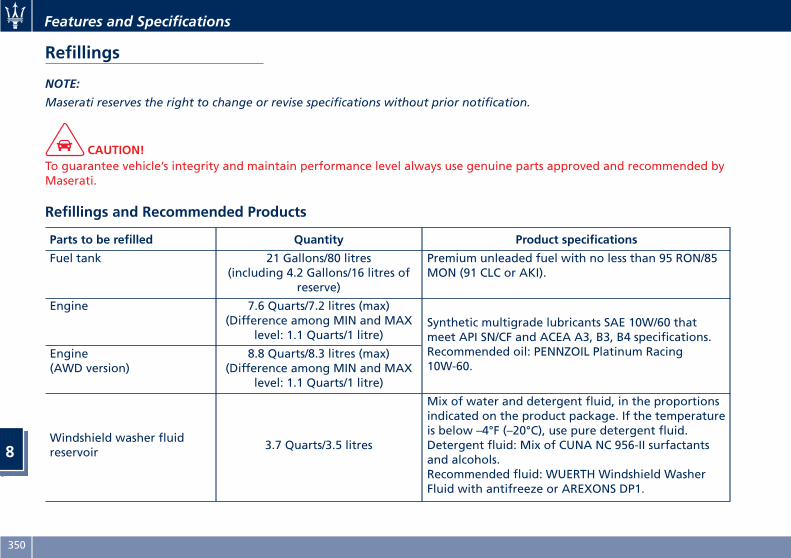
Refillings
NOTE:
Maserati reserves the right to change or revise specifications without prior notification.
CAUTION!To guarantee vehicle’s integrity and maintain performance level always use genuine parts approved and recommended byMaserati.
Refillings and Recommended Products
Parts to be refilled Quantity Product specifications
Fuel tank 21 Gallons/80 litres(including 4.2 Gallons/16 litres of
reserve)
Premium unleaded fuel with no less than 95 RON/85MON (91 CLC or AKI).
Engine 7.6 Quarts/7.2 litres (max)(Difference among MIN and MAX
level: 1.1 Quarts/1 litre)Synthetic multigrade lubricants SAE 10W/60 thatmeet API SN/CF and ACEA A3, B3, B4 specifications.Recommended oil: PENNZOIL Platinum Racing10W-60.
Engine(AWD version)
8.8 Quarts/8.3 litres (max)(Difference among MIN and MAX
level: 1.1 Quarts/1 litre)
Windshield washer fluidreservoir
3.7 Quarts/3.5 litres
Mix of water and detergent fluid, in the proportionsindicated on the product package. If the temperatureis below –4°F (–20°C), use pure detergent fluid.Detergent fluid: Mix of CUNA NC 956-II surfactantsand alcohols.Recommended fluid: WUERTH Windshield WasherFluid with antifreeze or AREXONS DP1.
Features and Specifications
8
350
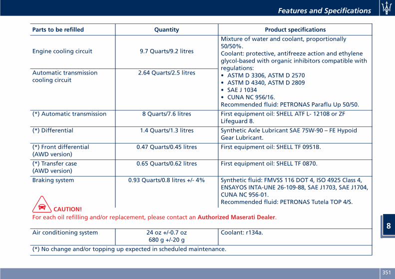
Parts to be refilled Quantity Product specifications
Engine cooling circuit 9.7 Quarts/9.2 litres
Mixture of water and coolant, proportionally50/50%.Coolant: protective, antifreeze action and ethyleneglycol-based with organic inhibitors compatible withregulations:• ASTM D 3306, ASTM D 2570• ASTM D 4340, ASTM D 2809• SAE J 1034• CUNA NC 956/16.Recommended fluid: PETRONAS Paraflu Up 50/50.
Automatic transmissioncooling circuit
2.64 Quarts/2.5 litres
(*) Automatic transmission 8 Quarts/7.6 litres First equipment oil: SHELL ATF L- 12108 or ZFLifeguard 8.
(*) Differential 1.4 Quarts/1.3 litres Synthetic Axle Lubricant SAE 75W-90 – FE HypoidGear Lubricant.
(*) Front differential(AWD version)
0.47 Quarts/0.45 litres First equipment oil: SHELL TF 0951B.
(*) Transfer case(AWD version)
0.65 Quarts/0.62 litres First equipment oil: SHELL TF 0870.
Braking system 0.93 Quarts/0.8 litres +/- 4% Synthetic fluid: FMVSS 116 DOT 4, ISO 4925 Class 4,ENSAYOS INTA-UNE 26-109-88, SAE J1703, SAE J1704,CUNA NC 956-01.Recommended fluid: PETRONAS Tutela TOP 4/S.
CAUTION!For each oil refilling and/or replacement, please contact an Authorized Maserati Dealer.
Air conditioning system 24 oz +/-0.7 oz680 g +/-20 g
Coolant: r134a.
(*) No change and/or topping up expected in scheduled maintenance.
Features and Specifications
8
351
WARNING!California Proposition 65Operating, servicing and maintaining a passenger vehicle or off-road vehicle can expose you to chemicals including suchas, engine exhaust, carbon monoxide, phthalates and lead, that which are know to the State of California to cause cancerand birth defects or other reproductive harm. To minimize exposure, avoid breathing exhaust, do not idle the engineexcept as necessary, service your vehicle in a well-ventilated area and wear gloves or wash your hands frequently whenservicing your vehicle. For more information go to: www.P65Warnings.ca.gov/passenger-vehicle
Engine Oil IdentificationSymbol
This symbol means that the oilhas been certified by theAmerican Petroleum Institute(API). Maserati only
recommends API Certified engine oils.
CAUTION!Do not use chemical flushes in yourengine oil as the chemicals candamage your engine. Damage causedby use of non-approved chemicals isnot covered by the new VehicleLimited Warranty.
Engine Oil Viscosity(SAE Grade)SAE 10W-60 engine oil isrecommended for all operatingtemperatures.The engine oil filler cap also shows therecommended engine oil viscosity foryour engine. For information onengine oil filler cap location, refer tochapter “Maintenance Procedures” insection “Maintenance and Care”.Lubricants that do not have both theengine oil certification mark and thecorrect SAE viscosity grade numbershould not be used.
Features and Specifications
8
352
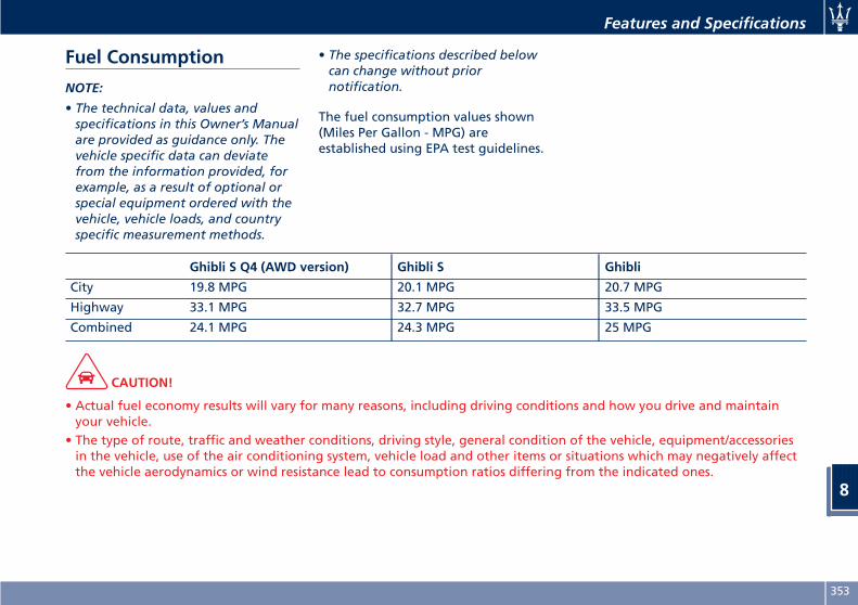
Fuel Consumption
NOTE:
• The technical data, values andspecifications in this Owner’s Manualare provided as guidance only. Thevehicle specific data can deviatefrom the information provided, forexample, as a result of optional orspecial equipment ordered with thevehicle, vehicle loads, and countryspecific measurement methods.
• The specifications described belowcan change without priornotification.
The fuel consumption values shown(Miles Per Gallon - MPG) areestablished using EPA test guidelines.
Ghibli S Q4 (AWD version) Ghibli S Ghibli
City 19.8 MPG 20.1 MPG 20.7 MPG
Highway 33.1 MPG 32.7 MPG 33.5 MPG
Combined 24.1 MPG 24.3 MPG 25 MPG
CAUTION!
• Actual fuel economy results will vary for many reasons, including driving conditions and how you drive and maintainyour vehicle.
• The type of route, traffic and weather conditions, driving style, general condition of the vehicle, equipment/accessoriesin the vehicle, use of the air conditioning system, vehicle load and other items or situations which may negatively affectthe vehicle aerodynamics or wind resistance lead to consumption ratios differing from the indicated ones.
Features and Specifications
8
353
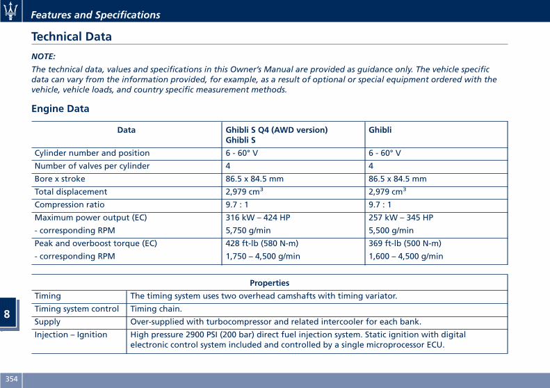
Technical Data
NOTE:
The technical data, values and specifications in this Owner’s Manual are provided as guidance only. The vehicle specificdata can vary from the information provided, for example, as a result of optional or special equipment ordered with thevehicle, vehicle loads, and country specific measurement methods.
Engine Data
Data Ghibli S Q4 (AWD version)Ghibli S
Ghibli
Cylinder number and position 6 - 60° V 6 - 60° V
Number of valves per cylinder 4 4
Bore x stroke 86.5 x 84.5 mm 86.5 x 84.5 mm
Total displacement 2,979 cm3 2,979 cm3
Compression ratio 9.7 : 1 9.7 : 1
Maximum power output (EC) 316 kW – 424 HP 257 kW – 345 HP
- corresponding RPM 5,750 g/min 5,500 g/min
Peak and overboost torque (EC) 428 ft-lb (580 N-m) 369 ft-lb (500 N-m)
- corresponding RPM 1,750 – 4,500 g/min 1,600 – 4,500 g/min
Properties
Timing The timing system uses two overhead camshafts with timing variator.
Timing system control Timing chain.
Supply Over-supplied with turbocompressor and related intercooler for each bank.
Injection – Ignition High pressure 2900 PSI (200 bar) direct fuel injection system. Static ignition with digitalelectronic control system included and controlled by a single microprocessor ECU.
Features and Specifications
8
354
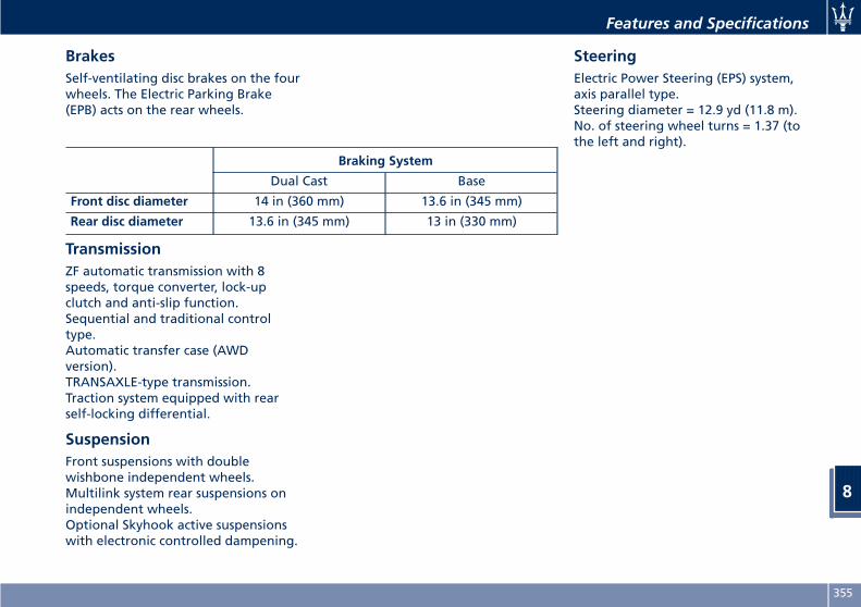
BrakesSelf-ventilating disc brakes on the fourwheels. The Electric Parking Brake(EPB) acts on the rear wheels.
TransmissionZF automatic transmission with 8speeds, torque converter, lock-upclutch and anti-slip function.Sequential and traditional controltype.Automatic transfer case (AWDversion).TRANSAXLE-type transmission.Traction system equipped with rearself-locking differential.
SuspensionFront suspensions with doublewishbone independent wheels.Multilink system rear suspensions onindependent wheels.Optional Skyhook active suspensionswith electronic controlled dampening.
SteeringElectric Power Steering (EPS) system,axis parallel type.Steering diameter = 12.9 yd (11.8 m).No. of steering wheel turns = 1.37 (tothe left and right).
Braking System
Dual Cast Base
Front disc diameter 14 in (360 mm) 13.6 in (345 mm)
Rear disc diameter 13.6 in (345 mm) 13 in (330 mm)
Features and Specifications
8
355
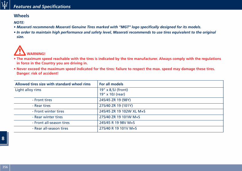
WheelsNOTE:•Maserati recommends Maserati Genuine Tires marked with “MGT” logo specifically designed for its models.• In order to maintain high performance and safety level, Maserati recommends to use tires equivalent to the originalsize.
WARNING!• The maximum speed reachable with the tires is indicated by the tire manufacturer. Always comply with the regulationsin force in the Country you are driving in.
• Never exceed the maximum speed indicated for the tires: failure to respect the max. speed may damage these tires.Danger: risk of accident!
Allowed tires size with standard wheel rims For all models
Light alloy rims 19” x 8,5J (front)19” x 10J (rear)
- Front tires 245/45 ZR 19 (98Y)
- Rear tires 275/40 ZR 19 (101Y)
- Front winter tires 245/45 ZR 19 102W XL M+S
- Rear winter tires 275/40 ZR 19 101W M+S
- Front all-season tires 245/45 R 19 98V M+S
- Rear all-season tires 275/40 R 19 101V M+S
Features and Specifications
8
356
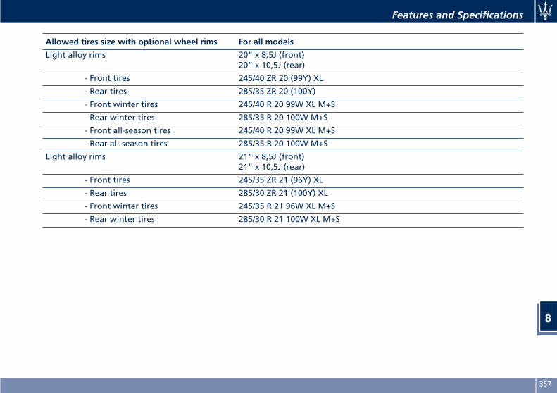
Allowed tires size with optional wheel rims For all models
Light alloy rims 20” x 8,5J (front)20” x 10,5J (rear)
- Front tires 245/40 ZR 20 (99Y) XL
- Rear tires 285/35 ZR 20 (100Y)
- Front winter tires 245/40 R 20 99W XL M+S
- Rear winter tires 285/35 R 20 100W M+S
- Front all-season tires 245/40 R 20 99W XL M+S
- Rear all-season tires 285/35 R 20 100W M+S
Light alloy rims 21” x 8,5J (front)21” x 10,5J (rear)
- Front tires 245/35 ZR 21 (96Y) XL
- Rear tires 285/30 ZR 21 (100Y) XL
- Front winter tires 245/35 R 21 96W XL M+S
- Rear winter tires 285/30 R 21 100W XL M+S
Features and Specifications
8
357
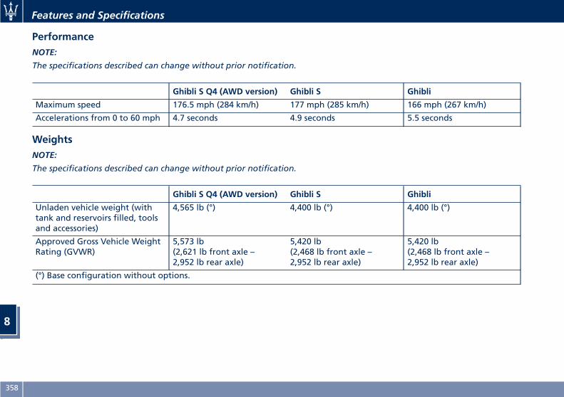
PerformanceNOTE:
The specifications described can change without prior notification.
Ghibli S Q4 (AWD version) Ghibli S Ghibli
Maximum speed 176.5 mph (284 km/h) 177 mph (285 km/h) 166 mph (267 km/h)
Accelerations from 0 to 60 mph 4.7 seconds 4.9 seconds 5.5 seconds
WeightsNOTE:
The specifications described can change without prior notification.
Ghibli S Q4 (AWD version) Ghibli S Ghibli
Unladen vehicle weight (withtank and reservoirs filled, toolsand accessories)
4,565 lb (°) 4,400 lb (°) 4,400 lb (°)
Approved Gross Vehicle WeightRating (GVWR)
5,573 lb(2,621 lb front axle –2,952 lb rear axle)
5,420 lb(2,468 lb front axle –2,952 lb rear axle)
5,420 lb(2,468 lb front axle –2,952 lb rear axle)
(°) Base configuration without options.
Features and Specifications
8
358
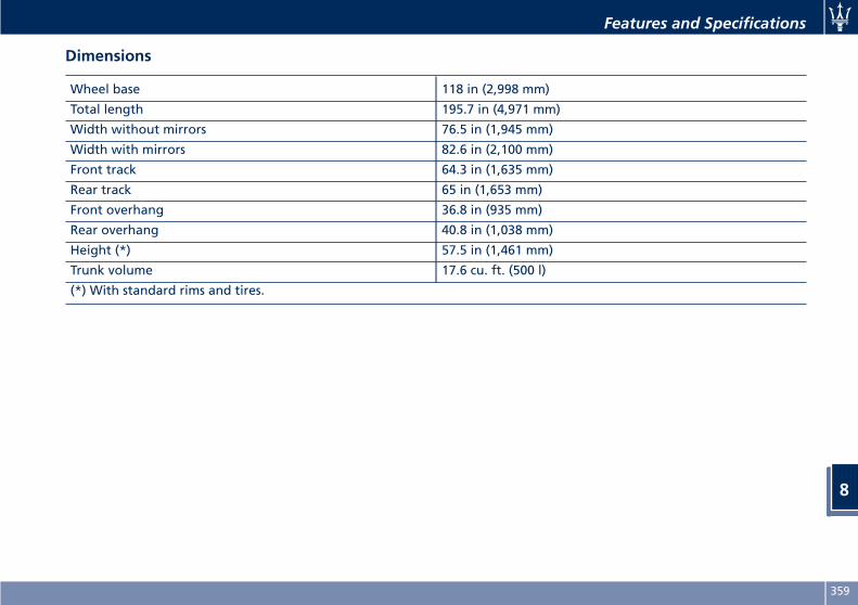
Dimensions
Wheel base 118 in (2,998 mm)
Total length 195.7 in (4,971 mm)
Width without mirrors 76.5 in (1,945 mm)
Width with mirrors 82.6 in (2,100 mm)
Front track 64.3 in (1,635 mm)
Rear track 65 in (1,653 mm)
Front overhang 36.8 in (935 mm)
Rear overhang 40.8 in (1,038 mm)
Height (*) 57.5 in (1,461 mm)
Trunk volume 17.6 cu. ft. (500 l)
(*) With standard rims and tires.
Features and Specifications
8
359
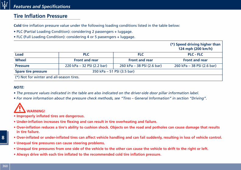
Tire Inflation Pressure
Cold tire inflation pressure value under the following loading conditions listed in the table below:
• PLC (Partial Loading Condition): considering 2 passengers + luggage.• FLC (Full Loading Condition): considering 4 or 5 passengers + luggage.
(*) Speed driving higher than124 mph (200 km/h)
Load PLC FLC PLC - FLC
Wheel Front and rear Front and rear Front and rear
Pressure 220 kPa – 32 PSI (2.2 bar) 260 kPa – 38 PSI (2.6 bar) 260 kPa – 38 PSI (2.6 bar)
Spare tire pressure 350 kPa – 51 PSI (3.5 bar)
(*) Not for winter and all-season tires.
NOTE:
• The pressure values indicated in the table are also indicated on the driver-side door pillar information label.• For more information about the pressure check methods, see “Tires – General Information” in section “Driving”.
WARNING!• Improperly inflated tires are dangerous.
• Under-inflation increases tire flexing and can result in tire overheating and failure.
• Over-inflation reduces a tire's ability to cushion shock. Objects on the road and potholes can cause damage that resultsin tire failure.
• Over-inflated or under-inflated tires can affect vehicle handling and can fail suddenly, resulting in loss of vehicle control.
• Unequal tire pressures can cause steering problems.
• Unequal tire pressures from one side of the vehicle to the other can cause the vehicle to drift to the right or left.
• Always drive with each tire inflated to the recommended cold tire inflation pressure.
Features and Specifications
8
360

9 – Index
361
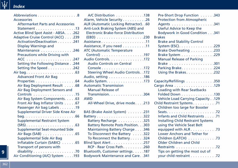
Abbreviations . . . . . . . . . . . . . . . . .8AccessoriesAftermarket Parts and AccessoriesStatement . . . . . . . . . . . . . . . . .13
Active Blind Spot Assist - ABSA . . . .262Adaptive Cruise Control (ACC) . . . .239Activation/Deactivation . . . . . . .241Display Warnings andMaintenance . . . . . . . . . . . . . .246Precautions while Driving withACC . . . . . . . . . . . . . . . . . . . .247Setting the Following Distance . .244Setting the Speed . . . . . . . . . . .242
Air bag . . . . . . . . . . . . . . . . . . . . .63Advanced Front Air BagProperties . . . . . . . . . . . . . . . . .64Air Bag Deployment Result . . . . .68Air Bag Deployment Sensors andControls . . . . . . . . . . . . . . . . . .15Air Bag System Components. . . . .63Front Air Bag Inflator Units . . . . .67Passenger Air bag Labels . . . . . . .19Supplemental Driver Side Knee Airbag. . . . . . . . . . . . . . . . . . . . . .66Supplemental Restraint System(SRS) . . . . . . . . . . . . . . . . . . . . .63Supplemental Seat-mounted SideAir Bags (SAB) . . . . . . . . . . . . . .65Supplemental Side Air BagInflatable Curtain (SABIC) . . . . . .65Transport of persons withdisability . . . . . . . . . . . . . . . . . .70
Air Conditioning (A/C) System . . . .193
A/C Distribution . . . . . . . . . . . .138Alarm, Vehicle Security . . . . . . . . . .26ALR (Automatic Locking Retractor). .60Anti-Lock Braking System (ABS) andElectronic Brake-force Distribution(EBD) . . . . . . . . . . . . . . . . . . . .230
Assistance . . . . . . . . . . . . . . . . . . .11Assistance, if you need . . . . . . . . . .11ATC (Automatic TemperatureControl) . . . . . . . . . . . . . . . . . .197
Audio Controls. . . . . . . . . . . . . . .172Audio Controls on CentralConsole . . . . . . . . . . . . . . . . . .172Steering Wheel Audio Controls . .172
Audio, setting . . . . . . . . . . . . . . .186Audio System. . . . . . . . . . . . . . . .173Automatic TransmissionManual Release ofTransmission. . . . . . . . . . . . . . .304
AWDAll-Wheel Drive, drive mode. . . .213
BAS (Brake Assist System) . . . . . . .231Battery . . . . . . . . . . . . . . . . . . . .322Battery Recharge . . . . . . . . . . .325Battery Remote Posts Position. . .303Maintaining Battery Charge . . . .346To Disconnect the Battery . . . . .322To Reconnect the Battery . . . . . .324
Blind Spot Alert . . . . . . . . . . . . . .257RCP - Rear Cross Path. . . . . . . . .260
Bluetooth, Customer settings . . . . .187Bodywork Maintenance and Care . .341
Pre-Short Drop Function . . . . . .343Protection from AtmosphericAgents . . . . . . . . . . . . . . . . . .341Useful Advice to Keep theBodywork in Good Condition . . .341
BrakesBrake and Stability ControlSystem (ESC). . . . . . . . . . . . . . .229Brake Overheating . . . . . . . . . .233Brake System . . . . . . . . . . . . . .229Manual Release of ParkingBrake . . . . . . . . . . . . . . . . . . .301Parking Brake. . . . . . . . . . . . . .224Using the Brakes . . . . . . . . . . . .232
Capacity/Refillings . . . . . . . . . . . .350Cargo Area . . . . . . . . . . . . . . . . .129Loading with Rear SeatbacksFolded Down . . . . . . . . . . . . . .130Vehicle Load Carrying Capacity . .129
Child Restraint Systems . . . . . . . . . .71Children too large for BoosterSeats. . . . . . . . . . . . . . . . . . . . .72Infants and Child Restraints . . . . .71Installing Child Restraint Systemsusing the Vehicle Seat Beltequipped with ALR . . . . . . . . . . .73Lower Anchors and Tether forChildren (LATCH) . . . . . . . . . . . .73Older Children and ChildRestraints . . . . . . . . . . . . . . . . .72Tips on getting the most out ofyour child restraint . . . . . . . . . . .72
Index
9
362
Climate Control . . . . . . . . . . . . . .193Clock, analog . . . . . . . . . . . . . . .181ConsoleCentral Console Components . . . .91Front Dome ConsoleComponents . . . . . . . . . . . . . . .91
Controls Screen . . . . . . . . . . . . . .175Cruise ControlCruise Control Adaptive (ACC) . .239Electronic Cruise Control (CC) . . .235
Cupholders . . . . . . . . . . . . . . . . .122Front Passengers Cupholders . . .123Rear Passengers Cupholders . . .124
Dashboard Compartment . . . . . . .189Dashboard Components . . . . . . . . .90Defroster . . . . . . . . . . . . . . . . . . .47DoorsChild Protection Door LockSystem . . . . . . . . . . . . . . . . . . .39Doors Locking . . . . . . . . . . . . . .38Doors Manual Lock. . . . . . . . . . .38Front Doors Components . . . . . .92Lock/Unlock Door Flashlight . . . .32Power Doors Locking/Unlocking . .38Rear Doors Components . . . . . . .93Soft Door Close System . . . . . . . .40Unlock Driver Door/All Doors withRemote Key 1st Press . . . . . . . . .32
DPF SystemDPF Filter Replacement . . . . . . .318
“Drive Away Inhibit” strategy . . . .228Drive Mode, controls . . . . . . . . . .214
Setting the Drive Mode . . . . . . .214Driving Conditions . . . . . . . . . . . .289Before the Trip. . . . . . . . . . . . .289Driving at Night . . . . . . . . . . . .290Driving in Fog . . . . . . . . . . . . .291Driving in the Mountains. . . . . .291Driving in the Rain . . . . . . . . . .290Driving on Snow or Ice . . . . . . .291Safe Driving. . . . . . . . . . . . . . .290
DRL (Daytime Running Light) . . . .108
EDR (Event Data Recorder) . . . . . . .70Electronic Cruise Control. . . . . . . .235Emergency . . . . . . . . . . . . . . . . . . .5Hazard Warning Lights . . . . . . .117In the Event of an Accident . . . .295Jump Starting . . . . . . . . . . . . .302Trunk Lid Emergency Release . . . .53
EngineEngine Coolant Level Check . . . .315Engine Oil Level Check . . . . . . .318Hood . . . . . . . . . . . . . . . . . . . .54Normal Starting of the Engine . .202Use of the Engine . . . . . . . . . . .233
Entry/Exit, lights on . . . . . . . . . . . .28EPB (Electric Parking Brake). . . . . .224ESC (Electronic Stability Control) . .229
FiltersA/C System Air FilterReplacement . . . . . . . . . . . . . .320Engine Air Filter Replacement . .320
Forward Collision Warning (FCW). .249
FuelCarbon Monoxide Warning . . . .287Emergency Fuel Filler DoorRelease . . . . . . . . . . . . . . . . . .289Emissions Inspection andMaintenance Programs . . . . . . .313Fuel Consumption . . . . . . . . . .353Fuel Filter Service . . . . . . . . . . .318Fuel Requirements . . . . . . . . . .285Fuel System Warnings . . . . . . . .286Gasoline/Oxygenate Blends . . . .286Low Fuel Indicator . . . . . . . . . .162Materials Added to Fuel . . . . . .286MMT in Gasoline . . . . . . . . . . .286Reformulated Gasoline . . . . . . .285
Fuses . . . . . . . . . . . . . . . . . . . . .327Fuses Position . . . . . . . . . . . . .327Fuses Replacement . . . . . . . . . .327
Glove Box Feature Lock(Passenger Side). . . . . . . . . . . . .190
Glove Box Lock FeatureHandholds and Cloth Hooks. . . .126
Hazard Warning Flashers . . . . . . .295Head Restraints . . . . . . . . . . . . . . .94Highway Assist - HAS . . . . . . . . . .266HomeLink . . . . . . . . . . . . . . . . . .134Security. . . . . . . . . . . . . . . . . .137Troubleshooting Tips. . . . . . . . .137Using HomeLink . . . . . . . . . . . .137
HoodOpen and Close the Hood . . . . . .54
Index
9
363
Hood Operation . . . . . . . . . . . . . .54HSA (Hill Start Assist) . . . . . . . . . .231
Identification Labels . . . . . . . . . . . .19Illuminated Entry/Exit . . . . . . . . . . .28Immobilizer (Sentry Key) . . . . . . . . .24Indicator LightsAir Bag Warning Light. . . . . . . . .82TFT Display: Menus andSettings . . . . . . . . . . . . . . . . .147TFT Display: Warning/IndicatorLights of Set Modes/Functions. . .159Warning and Indicator Lights onAnalog Instrument . . . . . . . . . .142
Infotainment System. . . . . . . . . . .165Infotelematic SystemMain Menu Bar on MTC+Display . . . . . . . . . . . . . . . . . .167Manual Controls and Devices . . .166Personalized the Main MenuBar . . . . . . . . . . . . . . . . . . . . .168
Instrument Cluster . . . . . . . . . . . .142Interior Components . . . . . . . . . . .90Interior Maintenance and Care. . . .344Interiors Features . . . . . . . . . . . . .121iPad Holder . . . . . . . . . . . . . . . . .127iPod Connection. . . . . . . . . . . . . .125
Jump Start Procedure . . . . . . . . . .303
Key Fob . . . . . . . . . . . . . . . . . . . .23Key Fob Battery Replacement. . . .33
Preventing Inadvertent Locking ofkey fob RKE Transmitter Inside theVehicle . . . . . . . . . . . . . . . . . . .42Replacement . . . . . . . . . . . . . . .25Requiring and setting AdditionalKey Fobs . . . . . . . . . . . . . . . . . .33Unlock the Vehicle with Key fob . .31
Keys . . . . . . . . . . . . . . . . . . . . . . .22
Lane Departure Warning (LDW) . . .253Level Checks . . . . . . . . . . . . . . . .315Adding Windshield . . . . . . . . . .317Brake Fluid Level Check . . . . . . .317Engine Coolant Level Check . . . .315Engine Oil Level Check. . . . . . . .315Fluid Level Check for CoolantTransmission System . . . . . . . . .320Transmission Oil Check. . . . . . . .319
LiftgateLiftgate and Hood AjarIndicators. . . . . . . . . . . . . . . . .162Unlatch the Trunk Lid . . . . . . . . .32
Lights . . . . . . . . . . . . . . . . . . . . .106Automatic High Beam . . . . . . . .109Bi-Xenon Headlight. . . . . . . . . .108Bulb Replacement . . . . . . . . . . .334Cargo Lamps . . . . . . . . . . . . . .117Dome Lights. . . . . . . . . . . . . . .116DRL, Daytime Running Lights . . .108Fog Lights . . . . . . . . . . . . . . . .111Full-LED Headlight withCornering Function . . . . . . . . . .109Headlight Time Delay . . . . . . . .108
High Beam and Flashing . . . . . .112Interior Lights. . . . . . . . . . . . . .113Light Switch . . . . . . . . . . . . . . .106Multifunction Lever. . . . . . . . . .111Turn Signals . . . . . . . . . . . . . . .111
Loading the VehicleLoading with Rear SeatbacksDown . . . . . . . . . . . . . . . . . . .130Vehicle Load Carrying Capacity . .129
Main- and Submenu . . . . . . . . . . .148Maintenance. . . . . . . . . . . . . . . . . .5A/C System Maintenance . . . . . .338Air Bag System Maintenance . . . .69Bodywork Maintenance andCare . . . . . . . . . . . . . . . . . . . .341Emissions Inspection andMaintenance Programs . . . . . . .313Interior Maintenance and Care . .344Maintenance Procedures . . . . . .314Periodic Maintenance . . . . . . . .311Scheduled Maintenance Service .308Scheduled Service Plan. . . . . . . .309Wheels Maintenance . . . . . . . . .339
Maserati Roadside AssistanceProgram . . . . . . . . . . . . . . . . . . .16
Mesh Pockets. . . . . . . . . . . . . . . .127Messages on Main Display Area . . .147MIL (Malfunction Indicator Light) . .143Mirrors . . . . . . . . . . . . . . . . . . . .103External Mirrors . . . . . . . . . . . .103Folding Mirrors. . . . . . . . . . . . .105
Index
9
364
Integrated External RearviewMirror Lights . . . . . . . . . . . . . .117Internal Rearview Mirror . . . . . .105Mirrors Positioning . . . . . . . . . .104Rearview Mirrors . . . . . . . . . . .103Tilt Mirrors in Reverse . . . . . . . .104
MTC+ “Controls” Screen . . . . . . . .175MTC+ Settings - CustomerProgrammable Features . . . . . . .178Auto-On Comfort & RemoteStart . . . . . . . . . . . . . . . . . . . .185Clear Personal Data . . . . . . . . .189Clock & Date . . . . . . . . . . . . . .181Display . . . . . . . . . . . . . . . . . .180Doors & Locks . . . . . . . . . . . . .184Engine Off Options . . . . . . . . . .186Lights . . . . . . . . . . . . . . . . . . .183Restore Settings . . . . . . . . . . . .189Safety and Driving Assistance . . .182Voice Commands . . . . . . . . . . .181
Occupant Restraint System . . . . . . .55On Board Diagnostics . . . . . . . . . .234ORC (Occupant RestraintController) . . . . . . . . . . . . . . . . .66
Park Assist . . . . . . . . . . . . . . . . . .84Enabling and Disabling ParkAssist . . . . . . . . . . . . . . . . . . . .87
Parking . . . . . . . . . . . . . . . . . . .227Parking Brake . . . . . . . . . . . . . . .224Passive Entry System . . . . . . . . . . .40Pedals, adjustable . . . . . . . . . . . .103
Pets, transporting . . . . . . . . . . . . .76Phone and Voice Controls onSteering Wheel . . . . . . . . . . . . .199Phone Mode . . . . . . . . . . . . . .200
Phone/Bluetooth, Customersettings . . . . . . . . . . . . . . . . . .187
Power Outlets . . . . . . . . . . . . . . .121Power Outlet Inside the CentralConsole. . . . . . . . . . . . . . . . . .122Power Outlet Inside theCupholder . . . . . . . . . . . . . . . .121Power Outlet Inside the Trunk . .122Rear Power Outlets. . . . . . . . . .122
Rear Parking Camera . . . . . . . . . . .76Refueling . . . . . . . . . . . . . . . . . .287Fuel Filler Neck Access . . . . . . . .287
Remote Start System . . . . . . . . . . .35Restarting the Vehicle . . . . . . . . .345Restraint System . . . . . . . . . . . . . .63Child Restraint Systems . . . . . . . .71
RKE (Remote Keyless Entry)Transmitter . . . . . . . . . . . . . . . . .22
Roadside Assistance Program . . . . .16Roll-Over Warning. . . . . . . . . . . . .15
SafetyChild Restraint Systems . . . . . . . .71Reporting Safety Defects. . . . . . .12
Safety Tips . . . . . . . . . . . . . . . . . .55Scheduled Maintenance Service . . .308
Scheduled Service PlanScheduled MaintenanceIndicator . . . . . . . . . . . . . . . . .308
Seat Belt . . . . . . . . . . . . . . . . . . .55Automatic Locking Retractor (ALR)Mode . . . . . . . . . . . . . . . . . . . .60Enhanced Seat Belt Use ReminderSystem (SBR) . . . . . . . . . . . . . . .61Passenger Seat Belts . . . . . . . . . .59Seat Belt Reminder Light . . . . . .146Seat Belts and PregnantWomen. . . . . . . . . . . . . . . . . . .62Seat Belts Pretensioners . . . . . . .61Three-Point Seat Belts. . . . . . . . .56Three-Point Seat Belts HeightAdjustment . . . . . . . . . . . . . . . .58Three-Point Seat Belts UntwistingProcedure . . . . . . . . . . . . . . . . .59Three-Point Seat Belts UseInstructions . . . . . . . . . . . . . . . .57Using the Seat Belt in AutomaticLocking Retractor Mode (ALR) . . .60
Seats . . . . . . . . . . . . . . . . . . . . . .93Driver Memory Seat . . . . . . . . . .97Easy Entry/Exit Seats . . . . . . . . . .98Front Heated Seats . . . . . . . . . . .95Front Power Seats . . . . . . . . . . .93Front Ventilated Seats. . . . . . . . .96Power Lumbar Seats . . . . . . . . . .94Rear Armrest . . . . . . . . . . . . . .100Rear Head Restraints . . . . . . . . .99Rear Seats . . . . . . . . . . . . . . . . .99Rear Side Heated Seats . . . . . . .100
Index
9
365
Seat Adjustment. . . . . . . . . . . . .94Service . . . . . . . . . . . . . . . . . . . . .10Siri Smart Personal Assistant . . . . .200Smoking Kit. . . . . . . . . . . . . . . . .126Snow Chains . . . . . . . . . . . . . . . .279Spare parts serviceGenuine Parts . . . . . . . . . . . . . .13Scheduled Maintenance . . . . . . .13
Spare Parts Service . . . . . . . . . . . . .13SRS (Supplemental RestraintSystem). . . . . . . . . . . . . . . . . . . .63
Start&Stop System . . . . . . . . . . . .204Occupant Safety Function . . . . .206Start&Stop Active Indicator . . . .144Start&Stop Disable Indicator. . . .163Start&Stop Failure IndicatorLight . . . . . . . . . . . . . . . . . . . .163Start&Stop Function DisablingIndicator . . . . . . . . . . . . . . . . .206Start&Stop Menu . . . . . . . . . . .154Start&Stop System Failure . . . . .207
Start the EngineEngine Start Failure. . . . . . . . . .203Engine Turn Off . . . . . . . . . . . .204
Steering WheelHeated Steering Wheel . . . . . . .102Phone and Voice Controls onSteering Wheel. . . . . . . . . . . . .199
SunroofPinch Protect Feature . . . . . . . .133Slide Opening Sunroof. . . . . . . .133Sunroof Maintenance . . . . . . . .134Venting Sunroof . . . . . . . . . . . .133
Sunshades . . . . . . . . . . . . . . . . . .132Power Sunshades . . . . . . . . . . . .47
Sun Visors . . . . . . . . . . . . . . . . . .125Surround View Camera System . . . .78Symbols . . . . . . . . . . . . . . . . . . . .14Danger Symbols . . . . . . . . . . . . .14Symbols of Prohibitions andCompulsory Measures . . . . . . . . .14
TCS (Traction Control System). . . . .231Technical Data . . . . . . . . . . . . . . .354TelltalesTelltales on Speedometer . . . . . .142Telltales on Tachometer . . . . . . .144Warning/Indicator Lights of SetModes/Functions on Display . . . .159
TFT Display: Menus and Settings. . .147TiresChange a Tire . . . . . . . . . . . . . .296Compact spare tire . . . . . . . . . .280Department of TransportationUniform Tire Quality Grades . . . .276General Information . . . . . . . . .274Inflation Pressure . . . . . . . . . . .360Punctured Tire, use . . . . . . . . . .296Replacement Tires . . . . . . . . . . .278Tire Pressure. . . . . . . . . . . . . . .277Tire Pressure Checkup . . . . . . . .277Tire Safety Information . . . . . . .274TPMS - Tire Pressure MonitoringSystem. . . . . . . . . . . . . . . . . . .280Winter Tires . . . . . . . . . . . . . . .279
Tool Kit . . . . . . . . . . . . . . . . . . . .294
TowingTowing a Disabled Vehicle . . . . .304Towing the Vehicle . . . . . . . . . .304Vehicle Towing Conditions . . . . .305
TPMS System . . . . . . . . . . . . . . . .280Tire Pressure Low Warning . . . . .282TPMS Deactivation . . . . . . . . . .284
Traffic Sign Assist - TSA . . . . . . . . .272Transmission, Automatic . . . . . . . .207Automatic Transmission Lever. . .208Automatic Transmission Range . .209Malfunction and OverheatingConditions . . . . . . . . . . . . . . . .211Transmission Manual Release ofP (Park) Position . . . . . . . . . . . .301
Transmitter, Key fob RKEPreventing Inadvertent Locking ofKey fob RKE Transmitter Inside theVehicle . . . . . . . . . . . . . . . . . . .42Radio Frequency RKETransmitter . . . . . . . . . . . . . . . .35
TrunkPower Trunk Lid/Hand Free(optional) . . . . . . . . . . . . . . . . .49Trunk Safety . . . . . . . . . . . . . . .53
Trunk LidPower Trunk Lid/Hand Free(optional) . . . . . . . . . . . . . . . . .49Trunk Lid Emergency Release frominside the Trunk . . . . . . . . . . . . .53Trunk Lid Operation . . . . . . . . . .48
Index
9
366
Updating . . . . . . . . . . . . . . . . . . . .9
Vehicle Identification Number(VIN) . . . . . . . . . . . . . . . . . . . . .18
Vehicle Stored for Long Periods . . .345Voice Commands . . . . . . . . . . . . .200
Warning icons. . . . . . . . . . . . . . . . .8Warnings when Driving . . . . . . . . .15Warranty . . . . . . . . . . . . . . . . . . .10Accessories . . . . . . . . . . . . . . . .10Warranty Information. . . . . . . . .12
Wheels . . . . . . . . . . . . . . . . . . . .339Wheels Maintenance . . . . . . . .339
Windows . . . . . . . . . . . . . . . . . . .45Auto Down/Auto Up Feature . . . .45Defroster . . . . . . . . . . . . . . . . .47Open the Windows with RKETransmitter and Ignition Off . . . .46Rear Window . . . . . . . . . . . . . .47Reset Auto-Up/Down . . . . . . . . .46Window and Sunshade LockoutButton . . . . . . . . . . . . . . . . . . .46
Wipers and Washers . . . . . . . . . . .118Headlight On with WindshieldWipers . . . . . . . . . . . . . . . . . .119Rain Sensing WindshieldWipers . . . . . . . . . . . . . . . . . .118Windshield Washers . . . . . . . . .120Windshield Wipers . . . . . . . . . .118Wipers Blades Maintenance . . . .119
Index
9
367
*1615945**1615945*
Maserati S.p.A. & Maserati North America, Inc. reserve the right to make changes and/or modifi cations to the content and all technical information and specifi cations without prior notifi cation.
Therefore, the user is not entitled to any claims based on the contents (texts, data, illustrations, explanations and regulations) in this manual, which are based on the data known at the time of going to print.
© 2017. Maserati S.p.A. All rights reserved.
Publication n. 910042022 - 1st Edition - 08/2017This document may not be reproduced, printed or translated, even partially, without the written consent of MASERATI S.p.A.

*910042022*
*910042022*
W W W . M A S E R A T I . C O M
M A S E R A T I S P A · V I A L E C I R O M E N O T T I , 3 2 2 · I - 4 1 1 2 1 M O D E N A
Top Related