


Languages
Pages
Legal


Digital Logic
CS 2420 – Husain Gholoom -‐ lecturer Page 1
Lecture – 5 -‐ Chapter 2
Outline Other Logic Gates and their uses Other Logic Operations

Digital Logic
CS 2420 – Husain Gholoom -‐ lecturer Page 2
Digital logic gates

Digital Logic
CS 2420 – Husain Gholoom -‐ lecturer Page 3
Buffer
A buffer is a gate with the function F = X:
In terms of Boolean function, a buffer is the same as a connection!
So why use it?
A buffer is an electronic amplifier used to improve circuit voltage levels and increase the speed of circuit operation.

Digital Logic
CS 2420 – Husain Gholoom -‐ lecturer Page 4
NAND Gate
The basic NAND gate has the following symbol, illustrated for three inputs:
AND-Invert (NAND)
NAND represents NOT AND, i. e., the AND function
with a NOT applied. The symbol shown is an AND-Invert. The small circle (“bubble”) represents the invert function.
Digital Logic
CS 2420 – Husain Gholoom -‐ lecturer Page 5
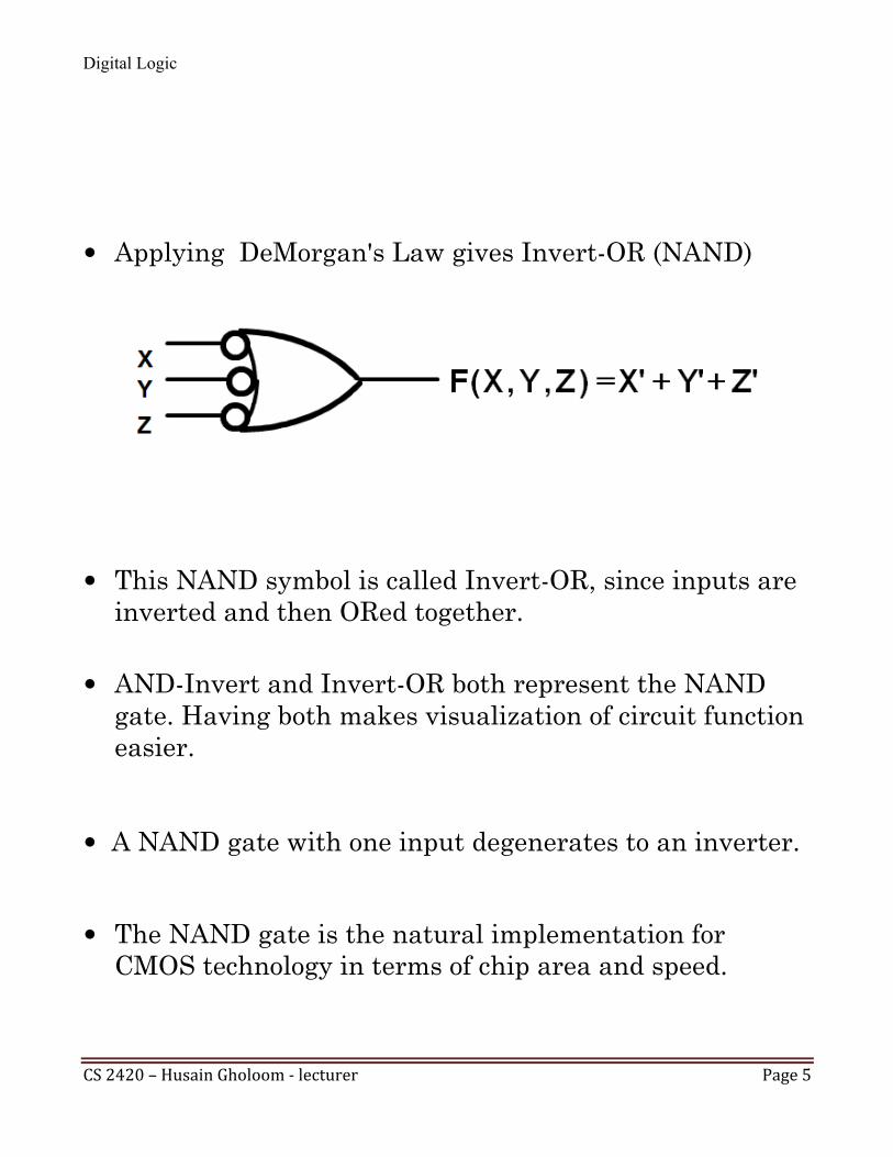
Applying DeMorgan's Law gives Invert-OR (NAND)
This NAND symbol is called Invert-OR, since inputs are inverted and then ORed together.
AND-Invert and Invert-OR both represent the NAND gate. Having both makes visualization of circuit function easier.
A NAND gate with one input degenerates to an inverter.
The NAND gate is the natural implementation for CMOS technology in terms of chip area and speed.
Digital Logic
CS 2420 – Husain Gholoom -‐ lecturer Page 6
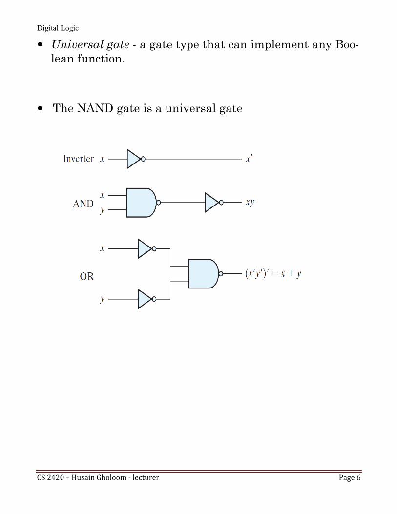
Universal gate - a gate type that can implement any Boo-lean function.
The NAND gate is a universal gate

Digital Logic
CS 2420 – Husain Gholoom -‐ lecturer Page 7
NAND circuit F = AB + CD

Digital Logic
CS 2420 – Husain Gholoom -‐ lecturer Page 8
F=xy'+x'y+z
1. Convert all AND gates to NAND gates with AND-invert graphic symbols 2. Convert all OR gates to NAND gates with invert-OR
graphic symbols
3. For every bubble that is not compensated by another small circle along the same line, insert an inverter or com-plement the input literal.
Digital Logic
CS 2420 – Husain Gholoom -‐ lecturer Page 9
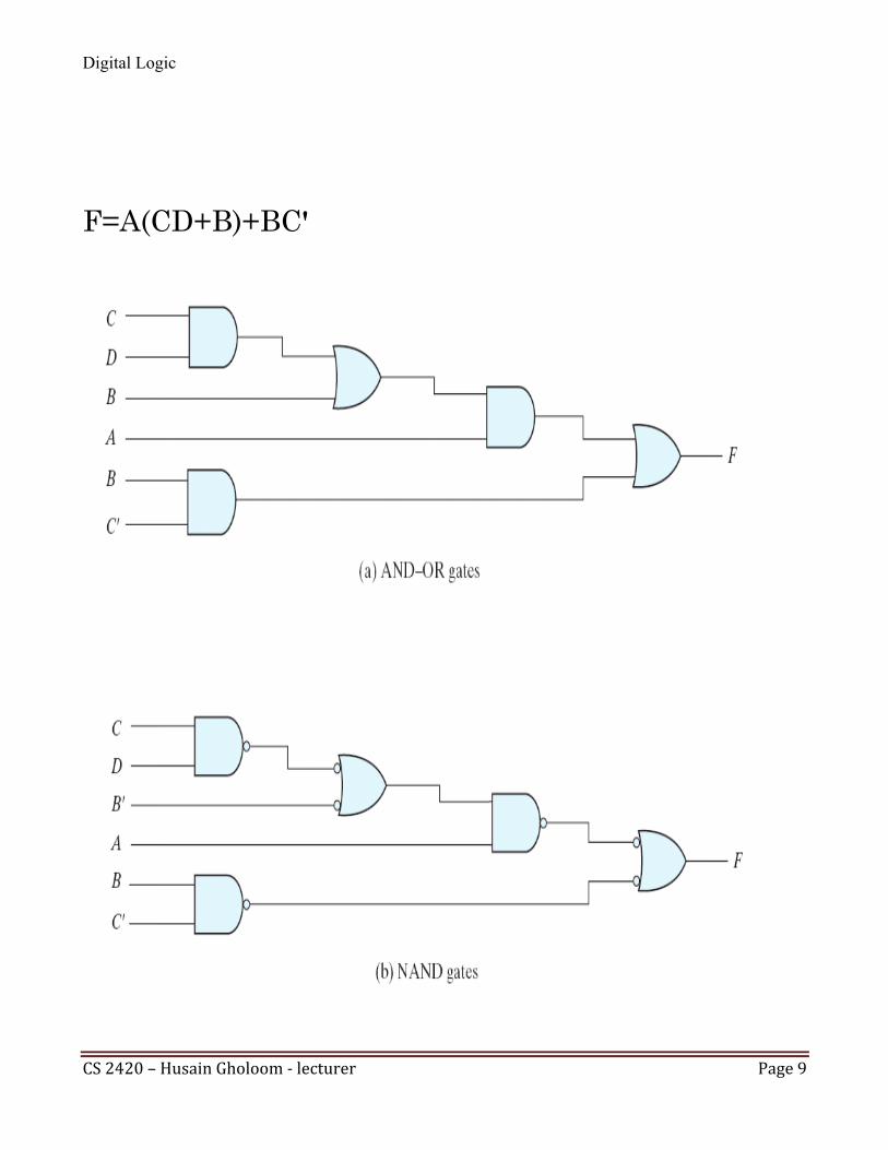
F=A(CD+B)+BC'
Digital Logic
CS 2420 – Husain Gholoom -‐ lecturer Page 10
NOR Gate
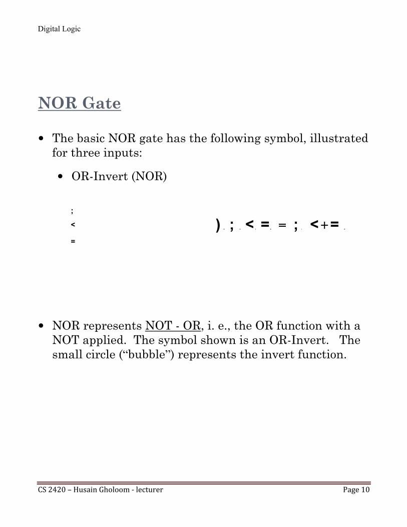
The basic NOR gate has the following symbol, illustrated for three inputs:
OR-Invert (NOR)
NOR represents NOT - OR, i. e., the OR function with a
NOT applied. The symbol shown is an OR-Invert. The small circle (“bubble”) represents the invert function.

Digital Logic
CS 2420 – Husain Gholoom -‐ lecturer Page 11
Applying DeMorgan's Law gives Invert-AND (NOR)
This NOR symbol is called Invert-AND, since inputs are
inverted and then ANDed together.
OR-Invert and Invert-AND both represent the NOR gate. Having both makes visualization of circuit function eas-ier.
A NOR gate with one input degenerates to an inverter. The NOR gate is a natural implementation for some
technologies other than CMOS in terms of chip area and speed.
Digital Logic
CS 2420 – Husain Gholoom -‐ lecturer Page 12
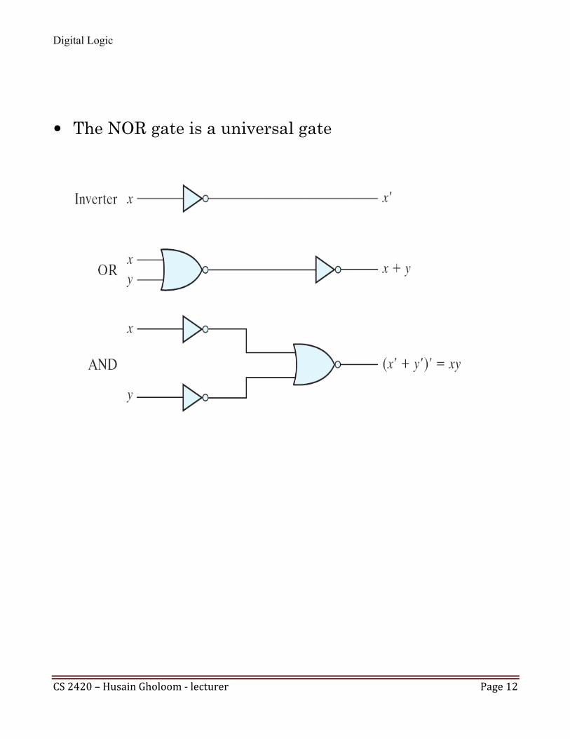
The NOR gate is a universal gate

Digital Logic
CS 2420 – Husain Gholoom -‐ lecturer Page 13
NOR circuit
F=(A+B)(C+D)E
Convert all OR gates to NOR gates with OR-invert
graphic symbols
Convert all AND gates to NOR gates with invert-AND graphic symbols
For every bubble that is not compensated by another small circle along the same line, insert an inverter or complement the input literal.

Digital Logic
CS 2420 – Husain Gholoom -‐ lecturer Page 14
Exclusive OR/ Exclusive NOR
The eXclusive OR (XOR) function is an important Boo-lean function used extensively in logic circuits.
The XOR function may be; implemented directly as an electronic circuit (truly a
gate) or implemented by interconnecting other gate types
(used as a convenient representation) The eXclusive NOR function is the complement of the
XOR function
Uses for the XOR and XNORs gate include:
Adders/subtractors/multipliers Counters/incrementers/decrementers Parity generators/checkers
Definitions The XOR function is: X Y = XY' + X'Y
The eXclusive NOR (XNOR) function,
otherwise
known as equivalence
⊕
Y'
X'
Y X Y) '
(X + = ⊕

Digital Logic
CS 2420 – Husain Gholoom -‐ lecturer Page 15
Truth Tables for XOR/XNOR
Operator Rules: XOR XNOR
The XOR function means:
X OR Y, but NOT BOTH
Why is the XNOR function also known as the equivalence function, denoted by the operator ≡?

Digital Logic
CS 2420 – Husain Gholoom -‐ lecturer Page 16
The XOR function can be extended to 3 or more
variables. For more than 2 variables, it is called an odd function.
The Truth Table
The complement of the odd function is the even function.
The XOR identities:
+ + + = ⊕ ⊕ Z Y X Z' Y' X Z' Y X' Z Y' X' Z Y X

Digital Logic
CS 2420 – Husain Gholoom -‐ lecturer Page 17
XOR symbol:
XNOR symbol:
Shaped symbols exist only for two inputs

Digital Logic
CS 2420 – Husain Gholoom -‐ lecturer Page 18
Example: Odd Function Implementation
Design a 3-input odd function with 2-input XOR gates
Factoring,
The circuit:

Digital Logic
CS 2420 – Husain Gholoom -‐ lecturer Page 19
Parity Generators and Checkers
In Chapter 1, a parity bit added to n-bit code to produce an n + 1 bit code: Add a parity bit to generate code words with even
parity

Digital Logic
CS 2420 – Husain Gholoom -‐ lecturer Page 20
PARITY CHECKERS
Use parity checker circuit to check code words with even parity

Digital Logic
CS 2420 – Husain Gholoom -‐ lecturer Page 21
PARITY GENERATORS AND CHECKERS Example: n = 3. Generate even
parity code words of length four with 3-bit even parity generator:
Check even parity code words Of length four with 4-bit even parity checker:
Operation: (X,Y,Z) = (0,0,1) gives (X,Y,Z,P) = (0,0,1,1) and E = 0. If Y changes from 0 to 1 between generator and checker, then E = 1 indicates an error.

Digital Logic
CS 2420 – Husain Gholoom -‐ lecturer Page 22
INFORMATION REPRESENTATION – Signals Example – Physical Quantity: Voltage Binary values are represented by values or ranges of values of physical quantities

Digital Logic
CS 2420 – Husain Gholoom -‐ lecturer Page 23
Circuit Attributes
Power dissipation: power consumed Noise margin: maximum external noise voltage added
in an input does not cause an undesirable change in output
Fan-out
The number of standard loads that can be connected to the output of the gate without degrading its nor-mal operation.
A standard load is the amount of current needed by an input of another gate.

Digital Logic
CS 2420 – Husain Gholoom -‐ lecturer Page 24
Circuit Attributes
In actual physical gates, if one or more input changes causes the output to change, the output change does not occur instantaneously.
The delay between an input change(s) and the resulting output change is the Propagation delay.
Top Related