


![Orbital Motors Type OMP X and OMR X - Danfossmineral based hydraulic oil with a viscosity of 35 mm2/s [165 SUS] and a temperature of 50 C [120 F]. Speed Maximum speed 25 32 40 125](https://static.fdocuments.us/doc/165x107/60ab141a0bbe462c6c09a0b2/orbital-motors-type-omp-x-and-omr-x-danfoss-mineral-based-hydraulic-oil-with-a.jpg)

Languages
Pages
Legal


Technical Information
Orbital MotorsType OMP X and OMR X
powersolutions.danfoss.com

Revision history Table of revisions
Date Changed Rev
January 2018 Major revision. 0201
February 2017 First edition. 0101
Technical InformationOrbital Motors Type OMP X and OMR X
2 | © Danfoss | January 2018 BC00000388en-US0201

General InformationOrbital Motors Introduction......................................................................................................................................................... 5Orbital Motors Features................................................................................................................................................................. 6
Technical Features...................................................................................................................................................................... 6Orbital Motors Application Areas............................................................................................................................................... 6Orbital Motors Literature Overview...........................................................................................................................................7Operating Parameters Diagrams................................................................................................................................................ 7
OMP X configuration versions overview with codes numbersOMP X standard motors.................................................................................................................................................................9
Side port offset 2-hole oval mounting flange (A2 flange)............................................................................................9Side port aligned 2-hole oval mounting flange (A2 flange)..................................................................................... 10Side port aligned with square mounting flange (C-flange)...................................................................................... 11Wheel mounting flange type............................................................................................................................................... 12
OMPW X N motors with needle bearings..............................................................................................................................13Wheel mounting flange type............................................................................................................................................... 13
OMP X motors with free running gerotor............................................................................................................................. 14Side port offset with 2-hole oval mounting flange (A2 flange)............................................................................... 14
OMP X Model Code
OMP X technical dataOMP X motor specification.........................................................................................................................................................18High Pressure Shaft Seal in OMP X and OMR X motors....................................................................................................19Pressure drop in OMP X motor..................................................................................................................................................19Oil flow in drain line...................................................................................................................................................................... 20Direction of shaft rotation: clockwise..................................................................................................................................... 20OMP X and OMR X shaft loads...................................................................................................................................................21OMP X N shaft loads......................................................................................................................................................................22OMPW X with slide bearings shaft loads............................................................................................................................... 23OMPW X N with needle bearing shaft loads........................................................................................................................ 24
OMP X function diagramsOMP X 25...........................................................................................................................................................................................25OMP X 32...........................................................................................................................................................................................26OMP X 40...........................................................................................................................................................................................26OMP X 50...........................................................................................................................................................................................27OMP X 80...........................................................................................................................................................................................27OMP X 100........................................................................................................................................................................................ 28OMP X 125........................................................................................................................................................................................ 28OMP X 160........................................................................................................................................................................................ 29OMP X 200........................................................................................................................................................................................ 29OMP X 250........................................................................................................................................................................................ 30OMP X 315........................................................................................................................................................................................ 30OMP X 400........................................................................................................................................................................................ 31
OMP X shaft versionOMP X and OMR X shaft versions.............................................................................................................................................32
OMP X port thread versionsMain port thread versions...........................................................................................................................................................35OMP X manifold mount............................................................................................................................................................... 35
OMP X dimensionsEU version side port offset with 2-hole oval mounting flange (A2-flange) ............................................................. 36EU version end port with 2-hole oval mounting flange (A2-flange)........................................................................... 37EU version OMPW X and OMPW X N motors wheel type................................................................................................ 38US version side port offset with 2-hole oval mounting flange (A2-flange).............................................................. 39US version side port aligned with 2-hole oval mounting flange (A2-flange) ..........................................................40US version side port aligned with square mounting flange (C-flange)......................................................................41
OMR X configuration versions overview with codes numbersOMR X standard motors.............................................................................................................................................................. 42
Technical InformationOrbital Motors Type OMP X and OMR X
Contents
© Danfoss | January 2018 BC00000388en-US0201 | 3

Side port offset 2-hole oval mounting flange (A2 flange)......................................................................................... 42Side port aligned with 2-hole oval mounting flange (A2 flange)........................................................................... 43Side port aligned with square mounting flange (C flange).......................................................................................44
OMR X N motors with needle bearings..................................................................................................................................45Side port offset 2-hole oval mounting flange (A2-flange).........................................................................................45
OMR X Model Code
OMR X technical dataOMR X motor specification.........................................................................................................................................................49High Pressure Shaft Seal in OMP X and OMR X motors....................................................................................................50Pressure drop in OMR X motor..................................................................................................................................................50Oil flow in drain line...................................................................................................................................................................... 51Direction of shaft rotation: clockwise..................................................................................................................................... 51OMP X and OMR X shaft loads...................................................................................................................................................52OMR X N with needle bearings shaft loads.......................................................................................................................... 53
OMR X function diagramsOMR X 50...........................................................................................................................................................................................54OMR X 80...........................................................................................................................................................................................55OMR X 100........................................................................................................................................................................................ 55OMR X 125........................................................................................................................................................................................ 56OMR X 160........................................................................................................................................................................................ 56OMR X 200........................................................................................................................................................................................ 57OMR X 250........................................................................................................................................................................................ 57OMR X 315........................................................................................................................................................................................ 58OMR X 375........................................................................................................................................................................................ 58OMR X 400........................................................................................................................................................................................ 59
OMR X Shaft versionOMP X and OMR X shaft versions.............................................................................................................................................60
OMR X port thread versionsMain port thread versions...........................................................................................................................................................63OMR X manifold mount...............................................................................................................................................................63
OMR X dimensionsEU version side port offset with 2-hole oval mounting flange (A2-flange).............................................................. 64EU version end port version with 2-hole oval mounting flange (A2-flange)........................................................... 65US version side port offset with 2-hole oval mounting flange (A2-flange).............................................................. 66US version side port aligned with 2 hole oval mounting flange (A2) ........................................................................ 67US version side port aligned with square mounting flange (C-flange)......................................................................68
Weight of motorsWeight of OMP X and OMR X motors..................................................................................................................................... 69
Technical InformationOrbital Motors Type OMP X and OMR X
Contents
4 | © Danfoss | January 2018 BC00000388en-US0201

Orbital Motors Introduction
Danfoss is a world leader within production of low speed orbital motors with high torque. We can offermore than 3000 different orbital motors, categorized in types, variants and sizes (including different shaftversions).
The motors size vary (rated displacement) from 8 to 800 cm3 [0.50 to 48.9 in3] per revolution.• Small sized motors:
‒ OML and OMM
• Medium sized motors:
‒ OMP, OMR and OMH
‒ OMP X and OMR X
‒ DH and DS
‒ OMEW
• Large sized motors:
‒ OMS, OMT and OMV
‒ TMK
‒ TMT
‒ TMTHW
‒ TMVW
Speeds range up to approximate 2500 min-1 (rpm) for the smallest type and up to approximate 600 min-1
(rpm) for the largest type.
Maximum operating torques vary from 13 to 4000 N•m [115 to 35 400 lb•in] (peak) and maximum outputsare from 2.0 to 95 kW [2.7 to 128 hp].
Wide range of Danfoss orbital motors
Technical InformationOrbital Motors Type OMP X and OMR X
General Information
© Danfoss | January 2018 BC00000388en-US0201 | 5

Orbital Motors Features
• Smooth running over the entire speed range
• Constant operating torque over a wide speed range
• High starting torque
• High return pressure without the use of drain line (high pressure shaft seal)
• High efficiency
• High radial and axial bearing capacity
• Long life under extreme operating conditions
• Robust and compact design
• For applications in both open and closed loop hydraulic systems
• Suitable for a wide variety of hydraulics fluids
Technical Features
The program is characterized by technical features appealing to a large number of applications and bymotors that can be adapted to a given application.
Adaptions comprise the following variants:• Motors with:
‒ corrosion resistant parts
‒ needle bearing (OMPW X N, OMR X N)
‒ low leakage version or super low leakage version (OMR, OMR X)
‒ integrated negative holding brake
‒ integrated flushing valve
‒ speed sensor
‒ tachometer connection
‒ black finish paint
• Short motors without bearings or Ultra short motors
• Wheel motors with recessed mounting flange
Orbital Motors Application Areas
The orbital motors are used in the following application areas:• Construction equipment
• Agricultural equipment
• Material handling & Lifting equipment
• Forestry equipment
• Lawn and turf equipment
• Machine tools and stationary equipment
• Marine equipment
• Special purpose
Technical InformationOrbital Motors Type OMP X and OMR X
General Information
6 | © Danfoss | January 2018 BC00000388en-US0201

Orbital Motors Literature Overview
A general catalog of all Orbital Motors with technical data gives a quick motor reference based on:selection of orbital motor, function in hydraulic systems, power, torque, speed and capabilities. Moredetailed information can be found in an individual motor catalogs.
Literature title Literature type Reference number
Orbital Motors in General Technical Information BC00000083
OML and OMM Orbital Motors Technical Information BC00000087
OMP, OMR and OMH Orbital Motors Technical Information BC00000084
OMS, OMT and OMV Orbital Motors Technical Information BC00000090
DH and DS Orbital Motors Technical Information BC00000092
OMEW Orbital Motors Technical Information BC00000062
TMK, TMKW, TMK FL Orbital Motors Technical Information BC00000098
TMT, TMTU, TMTW, TMT FL Orbital Motors Technical Information BC00000102
TMTHW Orbital Motors Technical Information BC00000230
Operating Parameters Diagrams
The bar diagrams are useful for a quick selection of relevant motor size for the application. The finalmotor size can be determined by using the function diagram for each motor size.
The function diagrams are based on actual tests on a representative number of motors from ourproduction. The diagrams apply to a return pressure between 5 and 10 bar [75 and 150 psi] when usingmineral based hydraulic oil with a viscosity of 35 mm2/s [165 SUS] and a temperature of 50°C [120°F].
Speed
Maximum speed
25 32 40 125
100
160
200
250
315 80 100
315
200
125
160
250
3755050 80
1800
1600
1200
1400
1000
200
400
600
800
OMP X OMR X
min-1
(rpm)
400
P109261
Technical InformationOrbital Motors Type OMP X and OMR X
General Information
© Danfoss | January 2018 BC00000388en-US0201 | 7
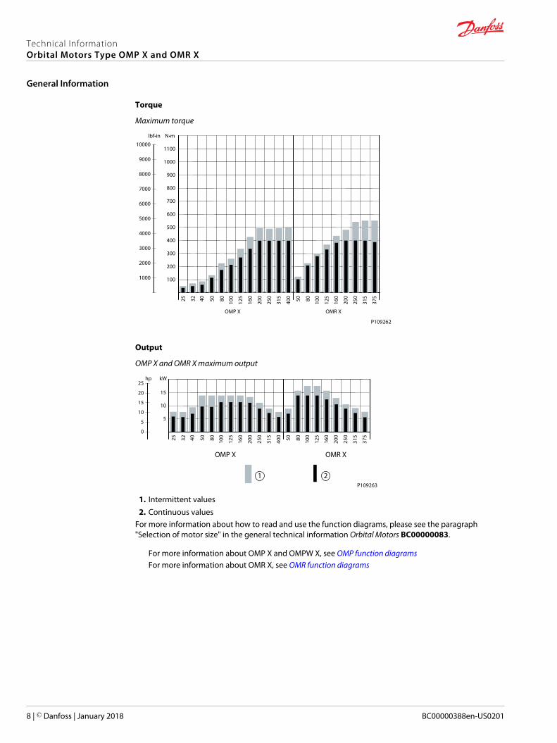
Torque
Maximum torque
100
200
300
400
500
800
600
700
900
1000
1100
OMP X OMR X
N•m
9000
lbf•in
8000
6000
7000
3000
2000
4000
5000
1000
10000
1003225 5040 80 100
125
160
200
250
315
400 50 80 250
160
125
200
315
375
P109262
Output
OMP X and OMR X maximum output
5
10
15
kW
OMP X OMR X
hp25
20
10
15
5
0
1003225 10040 50 80 250
200
160
125
400
315 50 80 250
200
125
160
375
315
1 2P109263
1. Intermittent values2. Continuous values
For more information about how to read and use the function diagrams, please see the paragraph"Selection of motor size" in the general technical information Orbital Motors BC00000083.
For more information about OMP X and OMPW X, see OMP function diagramsFor more information about OMR X, see OMR function diagrams
Technical InformationOrbital Motors Type OMP X and OMR X
General Information
8 | © Danfoss | January 2018 BC00000388en-US0201

The following tables show the different versions configuration codes.• OMP X standard motors:
‒ Side port offset 2-hole oval mounting flange (A2 flange) on page 9
‒ Side port aligned 2-hole oval mounting flange (A2 flange) on page 10
‒ Side port aligned with square mounting flange (C-flange) on page 11
‒ Wheel mounting flange type on page 12
• OMPW X N motors with needle bearings: Wheel mounting flange type on page 13
• OMP X motors with free running gerotor: Side port offset with 2-hole oval mounting flange (A2 flange)on page 14
If the desired OMP X could not be found please use the OMP X Model Code on page 15.
OMP X standard motors
For ordering please use the code numbers shown in the table on the following pages.
For OMP X motors with a configuration which is not available in the code number tables please use themodel code number system in the OMP X Model Code on page 15 to specify the OMP X motor on detail.
Side port offset 2-hole oval mounting flange (A2 flange)
Configuration code numbers are set according to OMP X motor mounting flange type.
Configuration codes A1 – A5 description
Pilot diameter Ø 82.5 mm [3.25 in]
Bolt circle dia. Ø 106.4 mm [4.20 in]
Conf. code A2 A1 A3 A4 A5
Shaft Cyl. Ø25 mm Cyl. Ø25 mm Cyl. 1 in Cyl. 1 in Splined 1 in
Main port G1/2 G1/2 G1/2 7/8 -14 UNF G1/2
Drain port G1/4 G1/4 G1/4 7/16-20 UNF G1/4
Port type End port Side port offset
Check valve Yes
Shaft seal High pressure shaft seal
Designation Main type designation: OMP X
Code numbers for configuration codes A1 – A5
Code Displacement
25 32 40 50 80 100 125* 160 200 250 315 400
A1 11185769 11185775 11186719 11185771 11186721 11186725 11185743 11186705 11186708 11186711 11186712 11186714
A2 – – 11185711 11185710 11185713 11185714 – 11185704 11185705 11185706 11185707 11185708
A3 – – – 11186729 11185808 11186730 11185792 11186726 11185796 11185798 11186728 11185802
A4 11185720 11185721 11185723 11185722 11185724 11185726 11185725 11185715 11185716 – 11185718 11185719
A5 – – – 11186738 11186739 11186740 11186731 11186732 11185819 11186820 11185827 11186737* Motor 11185725 is painted black.
Technical InformationOrbital Motors Type OMP X and OMR X
OMP X configuration versions overview with codes numbers
© Danfoss | January 2018 BC00000388en-US0201 | 9

Side port aligned 2-hole oval mounting flange (A2 flange)
Configuration code numbers are set according to OMP X motor mounting flange type.
Configuration codes A6 – A10 description
Pilot diameter Ø 82.5 mm [3.25 in]
Bolt circle dia. Ø 106.4 mm [4.20 in]
Conf. code A6 A7 A8 A9 A10
Shaft Cyl. 1 in Cyl. 1 in Splined 1 in Cyl. 1 in; CH 8 Cyl. 1 in; CH 10.3
Main port 7/8–14 UNF 1/2–14 UNF 7/8–14 UNF 7/8–14 UNF 7/8–14 UNF
Drain port 7/16-20 UNF
Port type Side port offset
Check valve Yes
Shaft seal High pressure shaft seal
Designation Main type designation: OMP X
Code numbers for codes A6 – A10 (Size 25 — 80 cm3)
Code Displacement
25 32 36 40 50 60 80
A6 – – 11186086 11186085 11186695 11186086 11186085
A7 – – 11186116 11186115 11186117 11186116 11186115
A8 – – 11186071 11186069 11186072 11186071 11186069
A9 83062875 83062884 83062885 83062886 83062887 83062888 11186092
A10 83062939 83062940 83062941 83062942 11186091 83062943 83062944
Code numbers for codes A6 – A10 (Size 100 — 400 cm3)
Code Displacement
100 125 160 200 250 315 400
A6 11186090 11186075 11186076 11186077 11186079 11186081 11186083
A7 11186118 — 11186110 11186111 11186112 11186113 11186818
A8 11186073 — 11186064 11186065 11186066 11186067 11186068
A9 11186093 83062889 83062890 83062891 83062902 83062903 83062904
A10 83062945 83062946 83062947 83062948 83062949 83062950 83062951
Technical InformationOrbital Motors Type OMP X and OMR X
OMP X configuration versions overview with codes numbers
10 | © Danfoss | January 2018 BC00000388en-US0201

Side port aligned with square mounting flange (C-flange)
Configuration code numbers are set according to OMP X motor mounting flange type.
Configuration codes B1 – B4 description
Pilot diameter Ø 44.4 mm [1.75 in]
Bolt circle diameter Ø 106.4 mm [4.20 in]
Conf. code B1 B2 B3 B4
Shaft Cylindrical 1 in Cylindrical 1 in Cyl. 1 in, CH8 Cyl. 1 in, CH10.3
Main port size 7/8–14 UNF 1/2–14 NPTF 7/8–14 UNF
Drain port size 7/16–20 UNF
Port type Side port aligned
Check valve Yes
Shaft seal High pressure shaft seal
Designation Main type designation: OMP X
Code numbers for B1 – B4 (Size 25 — 80 cm3)
Code Displacement
25 32 36 40 50 60 80
B1 – – 11186056 – 11186054 – 11186693
B2 – – 11186132 – 11186131 – 11186133
B3 83062956 83062957 83062958 83062959 83062960 83062961 83062992
B4 83063000 83063001 83063002 83063003 11186060 83063004 11186061
Code numbers for B1 – B4 (Size 100 — 400 cm3)
Code Displacement
100 125 160 200 250 315 400
B1 11186059 11186691 11186044 11186046 11186047 11186049 11186052
B2 11186134 11186125 11186126 11186127 11186128 11186129 11186130
B3 83062993 83062994 83062995 83062996 83062997 83062998 83062999
B4 11186062 83063005 83063006 83063007 83063008 83063009 83063010
Technical InformationOrbital Motors Type OMP X and OMR X
OMP X configuration versions overview with codes numbers
© Danfoss | January 2018 BC00000388en-US0201 | 11

Wheel mounting flange type
Configuration code number is set according to OMPW X motor mounting flange Wheel type.
Configuration code C1 description
Configuration code C1
Pilot diameter Ø 80 mm [3.15 in]
Bolt circle diameter Ø 103 mm [4.06 in]
Shaft Cylindrical Ø 25 mm [Dia 0.984 in]
Main port size G1/2
Drain port size G1/4
Port type Side port
Check valve Yes
Shaft seal High pressure shaft seal
Designation Main type designation: OMPW X
Code numbers for C1
Code Displacement
40 50 80 100 125 160 200 250 315 400
C1 11185874 11185873 11185875 11185877 11185876 11186746 11186747 11185870 11185871 11185872
Technical InformationOrbital Motors Type OMP X and OMR X
OMP X configuration versions overview with codes numbers
12 | © Danfoss | January 2018 BC00000388en-US0201

OMPW X N motors with needle bearings
Wheel mounting flange type
Configuration code number is set according to OMPW X N motor mounting flange Wheel type.
Configuration code E1 description
Configuration code E1
Pilot diameter Ø 80 mm [3.15 in]
Bolt circle diameter Ø 103 mm [4.06 in]
Shaft Tapered Ø 28.5 mm [Dia 1.122 in]
Main port size G1/2
Drain port size G1/4
Port type Side port
Check valve Yes
Shaft seal High pressure shaft seal
Designation Main type designation: OMPW X N
Code numbers for E1
Code Displacement
25 40 50 80 100 125 160 200 250 315 400
E1 11185887 11185889 11185888 11185890 11185892 11186750 11185882 11186748 11185884 11185885 11185886
Technical InformationOrbital Motors Type OMP X and OMR X
OMP X configuration versions overview with codes numbers
© Danfoss | January 2018 BC00000388en-US0201 | 13

OMP X motors with free running gerotor
Side port offset with 2-hole oval mounting flange (A2 flange)
Configuration code F1 is set according to OMP X motor mounting flange type: Side port offset with 2-hole oval mounting flange (A2-flange).
Configuration code F1 description
Configuration code F1
Pilot diameter Ø 82.5 mm [3.25 in]
Bolt circle diameter Ø 106.4 mm [4.20 in]
Shaft Cylindrical Ø 25 mm [Dia 0.984 in]
Main port size G1/2
Drain port size G1/4
Port type Side port offset
Check valve Yes
Shaft seal High pressure shaft seal
Designation Main type designation: OMP X
Code numbers for F1
Code Displacement
100 125 160 200 315
F1 11185790 11185746 11186707 11185751 11185761
Technical InformationOrbital Motors Type OMP X and OMR X
OMP X configuration versions overview with codes numbers
14 | © Danfoss | January 2018 BC00000388en-US0201
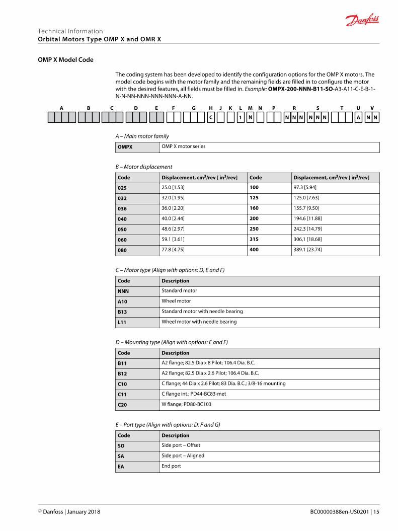
The coding system has been developed to identify the configuration options for the OMP X motors. Themodel code begins with the motor family and the remaining fields are filled in to configure the motorwith the desired features, all fields must be filled in. Example: OMPX-200-NNN-B11-SO-A3-A11-C-E-B-1-N-N-NN-NNN-NNN-NNN-A-NN.
B C D FE K M N SRPA
A
G H
C 1 N
J
N N N N N N
T
N N
L U V
A – Main motor family
OMPX OMP X motor series
B – Motor displacement
Code Displacement, cm3/rev [ in3/rev] Code Displacement, cm3/rev [ in3/rev]
025 25.0 [1.53] 100 97.3 [5.94]
032 32.0 [1.95] 125 125.0 [7.63]
036 36.0 [2.20] 160 155.7 [9.50]
040 40.0 [2.44] 200 194.6 [11.88]
050 48.6 [2.97] 250 242.3 [14.79]
060 59.1 [3.61] 315 306,1 [18.68]
080 77.8 [4.75] 400 389.1 [23.74]
C – Motor type (Align with options: D, E and F)
Code Description
NNN Standard motor
A10 Wheel motor
B13 Standard motor with needle bearing
L11 Wheel motor with needle bearing
D – Mounting type (Align with options: E and F)
Code Description
B11 A2 flange; 82.5 Dia x 8 Pilot; 106.4 Dia. B.C.
B12 A2 flange; 82.5 Dia x 2.6 Pilot; 106.4 Dia. B.C.
C10 C flange; 44 Dia x 2.6 Pilot; 83 Dia. B.C.; 3/8-16 mounting
C11 C flange int.; PD44-BC83-met
C20 W flange; PD80-BC103
E – Port type (Align with options: D, F and G)
Code Description
SO Side port – Offset
SA Side port – Aligned
EA End port
Technical InformationOrbital Motors Type OMP X and OMR X
OMP X Model Code
© Danfoss | January 2018 BC00000388en-US0201 | 15

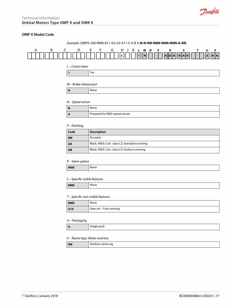
Example: OMPX-200-NNN-B11-SO-A3-A11-C-E-B-1-N-N-NN-NNN-NNN-NNN-A-NN.
B C D FE K M N SRPAA
G H
C 1 N
J
N N N N N N
T
N N
L U V
F – Main ports thread type
Code Description
A3 G 1/2
A8 7/8-14 UNF
A9 1/2-14 NPTF
B7 M22 x 1,5 according to ISO 6149
C1 Manifold
G – Shaft type (Align with options: C, F and K)
Code Description
A11 Cylindrical 25 mm with 8 mm key; M8 hole in shaft end
B11 Cylindrical 1 inch with 1/4 in key; M8 hole in shaft end
B12 Cylindrical 1 inch with 1/4 in key; 1/4-20UNC hole in shaft end
B13 Cylindrical 1 inch with Woodruff key; 1/4-20UNC hole in shaft end
B14 Cylindrical 1 inch with cross hole 10.3; 1/4-20UNC hole in shaft end
B15 Cylindrical 1 inch with cross hole 8.0
C11 Spline 7/8" – 13T
C13 1 inch 6B Spline; M8 hole in shaft end
C14 1 inch 6B Spline; 1/4-20UNC hole in shaft end
E10 Tapered 28.5 mm – 1:10
F10 Tapered 1" – 1:8, WK3/16x3/4
H – Shaft seal
C High pressure shaft seal - NBR
J – Dust seal
Code Description
B Dust seal integrated in shaft seal plus seal guard
E Dust seal integrated in shaft seal
K – Drain port (Align with options: F and G)
Code Description
B G1/4
D 7/16 – 20 UNF
K M12 x 1,5 according to ISO 6149
M No drain port due to EMD
Technical InformationOrbital Motors Type OMP X and OMR X
OMP X Model Code
16 | © Danfoss | January 2018 BC00000388en-US0201
Example: OMPX-200-NNN-B11-SO-A3-A11-C-E-B-1-N-N-NN-NNN-NNN-NNN-A-NN.
B C D FE K M N SRPAA
G HC 1 N
JN N N N N N
T
N N
L U V
A
L – Check Valve
1 Yes
M – Brake release port
N None
N – Speed sensor
N None
A Prepared for EMD speed sensor
P – Painting
Code Description
NN No paint
AA Black, 9005; Corr. class C3; Standard covering
AB Black, 9005; Corr. class C3; Surface covering
R – Valve option
NNN None
S – Specific visible features
NNN None
T – Specific non-visible features
NNN None
G10 Gear set – Free running
U – Packaging
A Single pack
V – Name tags: Motor and box
NN Danfoss name tag
Technical InformationOrbital Motors Type OMP X and OMR X
OMP X Model Code
© Danfoss | January 2018 BC00000388en-US0201 | 17

OMP X motor specification
OMP X motors, sizes: 25 – 100 cm³
Description Unit 25 32 40 50 80 100
Geometric displacement cm³ [in] 25.0 [1.53] 32.0 [1.96] 40.0 [2.45] 48.6 [2.97] 77.8 [4.76] 97.3 [5.95]
Max. speed cont. min-1 (rpm) 1600 1560 1500 1230 770 615
int.2) 1800 1720 1750 1550 960 770
Max. torque1) cont. N•m [lb•in] 40 [355] 50 [445] 52 [460] 110 [975] 170 [1505] 210 [1860]
int.2) 50 [445] 70 [620] 90 [795] 125 [1105] 220 [1950] 260 [2300]
Max. output cont. kW [hp] 5.4 [7.2] 6.7 [9.0] 7.0 [9.4] 9.8 [13.1] 9.8 [13.1] 11.2 [15.0]
int.2) 7.5 [10.0] 9.3 [12.5] 11.2 [15.0] 14.0 [18.8] 14.0 [18.8] 14.0 [18.8]
Max. pressuredrop
cont. bar [psi] 115 [1670] 115 [1670] 115 [1670] 160 [2320] 160 [2320] 160 [2320]
int.2) 160 [2320] 160 [2320] 160 [2320] 200 [2900] 200 [2900] 200 [2900]
Max. starting pressure withunloaded shaft
bar [psi] 10 [145] 10 [145] 10 [145] 10 [145] 10 [145] 10 [145]
Max. oil flow cont. l/min[US gal/min]
40 [10.6] 50 [13.2] 60 [15.9] 60 [15.9] 60 [15.9] 60 [15.9]
int.2) 45 [11.9] 55 [14.5] 70 [18.5] 75 [19.8] 75 [19.8] 75 [19.8]
Min startingtorque at max.pressure drop
cont. N•m [lb•in] 35 [310] 45 [400] 55 [485] 155 [1370] 135 [1200] 190 [1680]
int.2) 50 [440] 65 [575] 75 [660] 190 [1680] 170 [1510] 240 [2125]
OMP X motors, sizes: 125 – 400 cm³
Description Unit 125 160 200 250 315 400
Geometric displacement cm³ [in] 125[7.65]
155.7[9.53]
194.6[11.91]
242.3[14.83]
306.1[18.73]
389.2[23.82]
Max. speed cont. min-1 (rpm) 480 385 310 250 195 155
int.2) 600 480 385 310 245 190
Max. torque1) cont. N•m [lb•in] 270 [2390] 335 [2965] 400 [3540] 400 [3540] 400 [3540] 400 [3540]
int.2) 335 [2965] 425 [3760] 495 [4380] 490 [4335] 495 [4380] 500 [4425]
Max. output cont. kW [hp] 11.2 [15.0] 11.2 [15.0] 10.9 [14.5] 8.4 [11.3] 7.0 [9.4] 5.3 [7.0]
int.2) 14.0 [18.8] 14.0 [18.8] 13.7 [18.3] 10.9 [14.5] 8.8 [11.7] 6.7 [8.9]
Max. pressuredrop
cont. bar [psi] 160 [2320] 160 [2320] 155 [2250] 120 [1740] 100 [1450] 75 [1090]
int.2) 200 [2900] 200 [2900] 195 [2830] 155 [2250] 125 [1810] 95 [1380]
Max. starting pressure withunloaded shaft
bar [psi] 9 [130] 7 [100] 5 [75] 5 [75] 5 [75] 5 [75]
Max. oil flow cont. l/min[US gal/min]
60 [15.9] 60 [15.9] 60 [15.9] 60 [15.9] 60 [15.9] 60 [15.9]
int.2) 75 [19.8] 75 [19.8] 75 [19.8] 75 [19.8] 75 [19.8] 75 [19.8]
Min startingtorque at max.pressure drop
cont. N•m [lb•in] 240 [2125] 320 [2830] 375 [3320] 375 [3320] 380 [3365] 370 [3275]
int.2) 300 [2655] 400 [3540] 470 [4160] 480 [4250] 475 [4205] 470 [4160]
1) Maximum torque values for the different output shafts can be found in OMP X shaft version on page 32.2) Intermittent operation, permissible values may occur for max. 10% of every minute.
Pressure limits
Description All sizes
Max. inlet pressure drop Continuous 200 bar [2900 psi]
Intermittent 225 bar [3260 psi]
Max. return pressure with drain line Continuous 200 bar [2900 psi]
Intermittent 225 bar [3260 psi]
Technical InformationOrbital Motors Type OMP X and OMR X
OMP X technical data
18 | © Danfoss | January 2018 BC00000388en-US0201

High Pressure Shaft Seal in OMP X and OMR X motors
OMP X and OMR X motors feature options with High Pressure Shaft Seal (HPS), with check valves and withor without drain connection.
HPS pressure in the drain connection
OMP X/OMR X with drain connection OMP X/OMR X without drain connection
The shaft seal pressure equals the pressure in the drainline
The shaft seal pressure never exceeds the pressure inthe return line
151-320.10
Maximum permissible shaft seal pressure
psi
3600
3000
2400
1800
1200
600
0
bar
250
200
150
100
50
00 100 200 300 400 500 600 700 800 1600
intermittent operation
Ø25 mm-Ø1”-Ø1” splined shaft
min-1 (rpm)
Pressure drop in OMP X motor
The curve applies to an unloaded motor shaft and an oil viscosity of 35 mm2/s [165 SUS]
0
5
10
15
20
25
Ql/min
bar30
80706050403020100
0 2 4 6 108 12 14 16 US gal/min18 20
Q
0
50
250
150
100
200
300
350
400
psi
∆p
151-1744.10
∆p
B
A
Technical InformationOrbital Motors Type OMP X and OMR X
OMP X technical data
© Danfoss | January 2018 BC00000388en-US0201 | 19

A: OMP X 50 - 400
B: OMP X 25 - 40 / OMPW X
Oil flow in drain line
Max. oil flow in the drain line at return pressure less 5-10 bar
Pressure drop 100 bar [1450 psi] 140 bar [2030 psi]
Viscosity 20 mm2/s [100 SUS] 35 mm2/s [165 SUS] 20 mm2/s [100 SUS] 35 mm2/s [165 SUS]
Max. oil flow 2.5 l/min[0.66 US gal/min]
1.8 l/min[0.78 US gal/min]
3.5 l/min[0.93 US gal/min]
2.8 l/min[0.74 US gal/min]
Direction of shaft rotation: clockwise
A
B B AB A
P109280
AB
Technical InformationOrbital Motors Type OMP X and OMR X
OMP X technical data
20 | © Danfoss | January 2018 BC00000388en-US0201
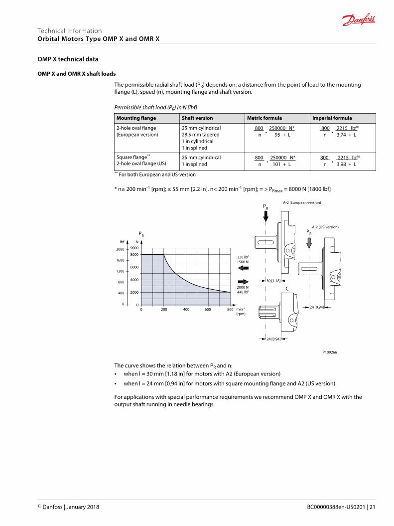
OMP X and OMR X shaft loads
The permissible radial shaft load (PR) depends on: a distance from the point of load to the mountingflange (L), speed (n), mounting flange and shaft version.
Permissible shaft load (PR) in N [lbf]
Mounting flange Shaft version Metric formula Imperial formula
2-hole oval flange(European version)
25 mm cylindrical28.5 mm tapered1 in cylindrical1 in splined
800 • 250000 N*
n 95 + L 800
• 2215 lbf*
n 3.74 + L
Square flange**
2-hole oval flange (US)25 mm cylindrical1 in splined
800 • 250000 N*
n 101 + L 800
• 2215 lbf*
n 3.98 + L
** For both European and US-version
* n≥ 200 min-1 [rpm]; ≤ 55 mm [2.2 in]. n< 200 min-1 [rpm]; = > PRmax = 8000 N [1800 lbf]
30 [1.18]
24 [0.94]
24 [0.94]
330 lbf1500 N
2000 N440 lbf
A-2 (European-version)
A-2 (US-version)
PR
PR
PR
C
lbf
2000
1600
1200
800
400
0
N9000
8000
6000
4000
2000
00 200 400 600 800 min-1
(rpm)
P109266
The curve shows the relation between PR and n:• when l = 30 mm [1.18 in] for motors with A2 (European version)
• when l = 24 mm [0.94 in] for motors with square mounting flange and A2 (US version)
For applications with special performance requirements we recommend OMP X and OMR X with theoutput shaft running in needle bearings.
Technical InformationOrbital Motors Type OMP X and OMR X
OMP X technical data
© Danfoss | January 2018 BC00000388en-US0201 | 21

OMP X N shaft loads
4400
4000
3600
3200
2800
2400
2000
1600
1200
800
400
0
20000
18000
16000
14000
12000
10000
8000
6000
4000
2000
0
151-2112.10
120 110 100 90 80 70 60 50 40 30 20 10 0 -10 -20 -30 mm
4 3 2 1 0 -1 in
lbf NPrad. Prad.
Pmax.
Pmax.
=
=
2000 N450 lbf
1500 N335 lbf
0 -
50 min-1
200 min-1
800 min-1
A
+
The output shaft on OMP X N can be offered in needle bearings. These bearings and the recessedmounting flange allow a higher permissible radial load in comparison to OMP X motors.
The permissible radial load on the shaft is shown for different speeds as a function of the distance fromthe mounting flange to the point of load application.
Curve A indicates the max. radial shaft load. Any shaft load exceeding the values quoted in curve A willinvolve risk of breakage.
The other curves apply to a B10 bearing life of 2000 hours at the number of revolutions indicated by thecurve letter. Mineral based hydraulic oil with a sufficient content of anti-wear additives must be used.
Bearing life calculations can be made using the explanation and formula provided in the chapter "Bearingdimensioning" in the technical information General Orbital Motors, BC00000083.
Technical InformationOrbital Motors Type OMP X and OMR X
OMP X technical data
22 | © Danfoss | January 2018 BC00000388en-US0201
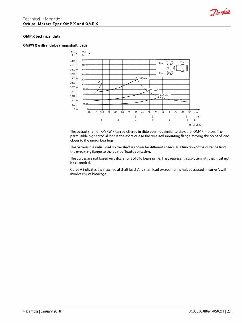
OMPW X with slide bearings shaft loads
4400
4000
3600
3200
2800
2400
2000
1600
1200
800
400
0
20000
18000
16000
14000
12000
10000
8000
6000
4000
2000
0
151-2105.10
120 110 100 90 80 70 60 50 40 30 20 10 0 -10 -20 -30 mm
4 3 2 1 0 -1 in
lbf NPrad. Prad.
Pmax.
Pmax.
=
=
2000 N450 lbf
1500 N335 lbf
0 -
400 min-1
200 min-1
800 min-1
A
A
+
The output shaft on OMPW X can be offered in slide bearings similar to the other OMP X motors. Thepermissible higher radial load is therefore due to the recessed mounting flange moving the point of loadcloser to the motor bearings.
The permissible radial load on the shaft is shown for different speeds as a function of the distance fromthe mounting flange to the point of load application.
The curves are not based on calculations of B10 bearing life. They represent absolute limits that must notbe exceeded.
Curve A indicates the max. radial shaft load. Any shaft load exceeding the values quoted in curve A willinvolve risk of breakage.
Technical InformationOrbital Motors Type OMP X and OMR X
OMP X technical data
© Danfoss | January 2018 BC00000388en-US0201 | 23

OMPW X N with needle bearing shaft loads
4400
4000
3600
3200
2800
2400
2000
1600
1200
800
400
0
20000
18000
16000
14000
12000
10000
8000
6000
4000
2000
0
151-2106.10
120 110 100 90 80 70 60 50 40 30 20 10 0 -10 -20 -30 mm
4 3 2 1 0 -1 in
lbf NPrad. Prad.
Pmax.
Pmax.
=
=
2000 N450 lbf
1500 N335 lbf
0-+
50 min-1
200 min-1
800 min-1
A
The output shaft on OMPW X N can be offered in needle bearings. These bearings and the recessedmounting flange allow a higher permissible radial load in comparison to OMP X motors.
The permissible radial load on the shaft is shown for different speeds as a function of the distance fromthe mounting flange to the point of load application.
Curve A indicates the max. radial shaft load. Any shaft load exceeding the values quoted in curve A willinvolve risk of breakage.
The other curves apply to a B10 bearing life of 2000 hours at the number of revolutions indicated by thecurve letter. Mineral based hydraulic oil with a sufficient content of anti-wear additives must be used.
Bearing life calculations can be made using the explanation and formula provided in the chapter "Bearingdimensioning" in the technical information General Orbital Motors, BC00000083.
Technical InformationOrbital Motors Type OMP X and OMR X
OMP X technical data
24 | © Danfoss | January 2018 BC00000388en-US0201

Explanation of function diagram use, basis and conditions can be found in Operating ParametersDiagrams on page 7.• Continuous range
• Intermittent range (max. 10% operation every minute)
Max. permissible continuous/intermittent pressure drop for the actual shaft version can be found in OMPX technical data on page 18.
Intermittent pressure drop and oil flow must not occur simultaneously.
OMP X 25
0 200 400 600 800 1000 1200 1400 1600 1800 2000
RPM [1/min]
0
5
10
15
20
25
30
35
40
45
50
55
60
Torq
ue [N
m]
0
50
100
150
200
250
300
350
400
450
500
Torq
ue [l
bf·in
]
Q=5
l/m
in[1
.3 U
S ga
l/min
]
10 l/
min
[2.6
US
gal/m
in]
15 l/
min
[4.0
US
gal/m
in]
20 l/
min
[5.3
US
gal/m
in]
25 l/
min
[6.6
US
gal/m
in]
30 l/
min
[7.9
US
gal/m
in]
35 l/
min
[9.2
US
gal/m
in]
40 l/
min
[10.
6 U
S ga
l/min
]
Q=4
5 l/m
in[1
1.9
US
gal/m
in]
140 bar[2030 psi]
∆ p=160 bar[2320 psi]
115 bar[1668 psi]
100 bar[1450 psi]
80 bar[1160 psi]
60 bar[870 psi]
∆ p=30 bar[440 psi]
N=10 hp
8 hp
6 hp
4 hp
2 hp
1 hp
6 kW
4 kW
2 kW
1 kW
ηt=78%
ηt=75%
ηt=70%
ηt=60%ηt=50%
ηt=70%
ηt=60%
ηt=50%
P109290
Technical InformationOrbital Motors Type OMP X and OMR X
OMP X function diagrams
© Danfoss | January 2018 BC00000388en-US0201 | 25
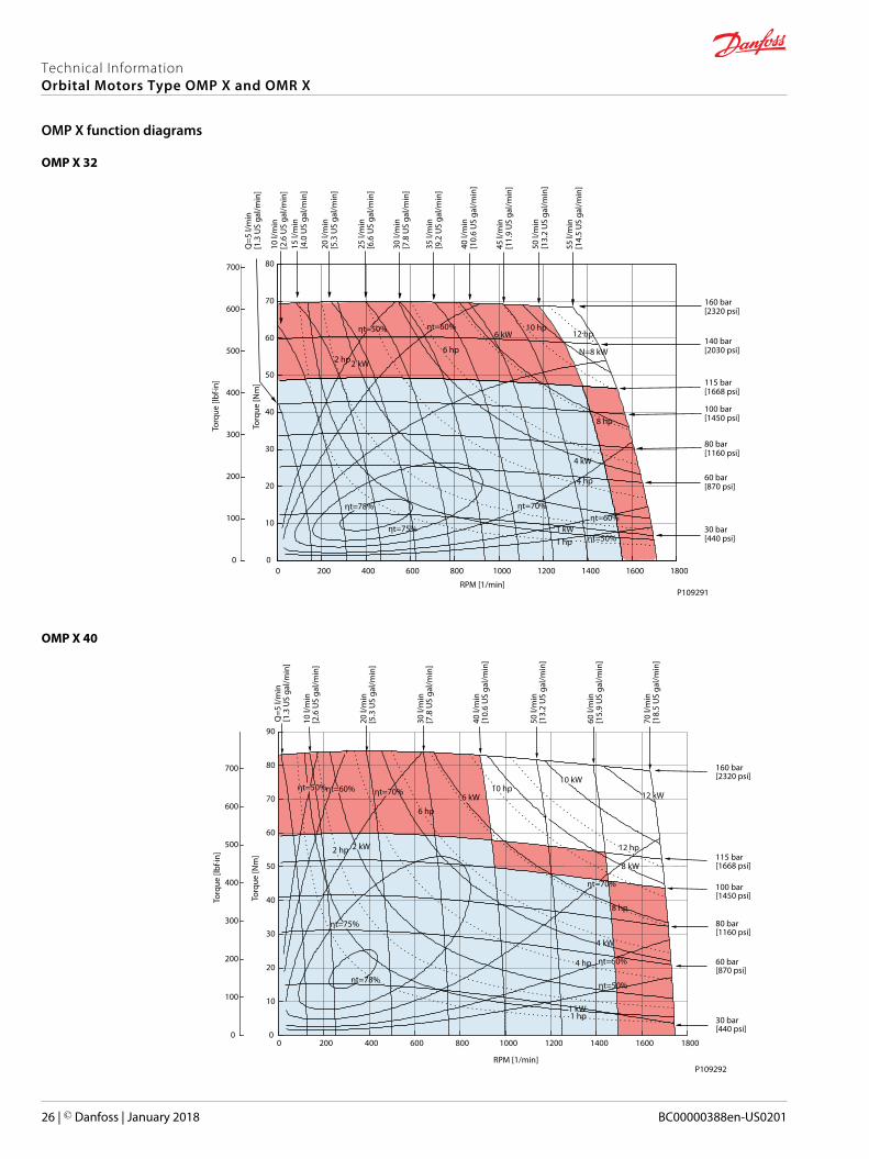
OMP X 32
P109291
0 200 400 600 800 1000 1200 1400 1600 1800
RPM [1/min]
0
10
20
30
40
50
60
70
80To
rque
[Nm
]
0
100
200
300
400
500
600
700
Torq
ue [l
bf·in
]
Q=5
l/m
in[1
.3 U
S ga
l/min
]
10 l/
min
[2.6
US
gal/m
in]
15 l/
min
[4.0
US
gal/m
in]
20 l/
min
[5.3
US
gal/m
in]
25 l/
min
[6.6
US
gal/m
in]
30 l/
min
[7.8
US
gal/m
in]
35 l/
min
[9.2
US
gal/m
in]
40 l/
min
[10.
6 U
S ga
l/min
]
45 l/
min
[11.
9 U
S ga
l/min
]
50 l/
min
[13.
2 U
S ga
l/min
]
55 l/
min
[14.
5 U
S ga
l/min
]
160 bar[2320 psi]
140 bar[2030 psi]
115 bar[1668 psi]
100 bar[1450 psi]
80 bar[1160 psi]
60 bar[870 psi]
30 bar[440 psi]
N=8 kW
4 kW
2 kW
1 kW
12 hp10 hp
6 kW
8 hp
6 hp
4 hp
2 hp
1 hp
ηt=50% ηt=60%
ηt=70%ηt=60%
ηt=50%ηt=75%
ηt=78%
OMP X 40
0 200 400 600 800 1000 1200 1400 1600 1800
RPM [1/min]
0
10
20
30
40
50
60
70
80
90
Torq
ue [N
m]
0
100
200
300
400
500
600
700
Torq
ue [l
bf·in
]
Q=5
l/m
in[1
.3 U
S ga
l/min
]
10 l/
min
[2.6
US
gal/m
in]
20 l/
min
[5.3
US
gal/m
in]
30 l/
min
[7.8
US
gal/m
in]
40 l/
min
[10.
6 U
S ga
l/min
]
50 l/
min
[13.
2 U
S ga
l/min
]
60 l/
min
[15.
9 U
S ga
l/min
]
70 l/
min
[18.
5 U
S ga
l/min
]
160 bar[2320 psi]
115 bar[1668 psi]
100 bar[1450 psi]
80 bar[1160 psi]
60 bar[870 psi]
30 bar[440 psi]
12 kW
10 kW
8 kW
6 kW
4 kW
2 kW
1 kW
12 hp
10 hp
8 hp
6 hp
4 hp
2 hp
1 hp
ηt=50%ηt=60% ηt=70%
ηt=75%
ηt=78%ηt=50%
ηt=60%
ηt=70%
P109292
Technical InformationOrbital Motors Type OMP X and OMR X
OMP X function diagrams
26 | © Danfoss | January 2018 BC00000388en-US0201
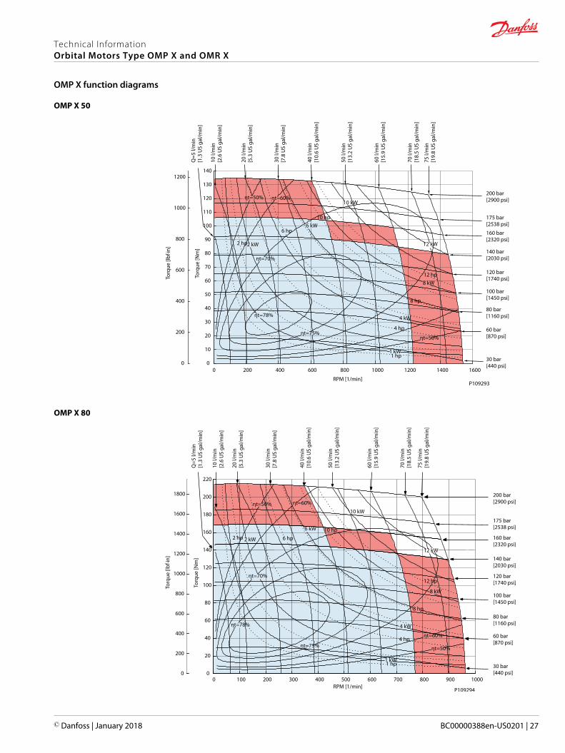
OMP X 50
0 200 400 600 800 1000 1200 1400 1600
RPM [1/min]
0
10
20
30
40
50
60
70
80
90
100
110
120
130
140
Torq
ue [N
m]
0
200
400
600
800
1000
1200
Torq
ue [l
bf·in
]
Q=5
l/m
in[1
.3 U
S ga
l/min
]
10 l/
min
[2.6
US
gal/m
in]
20 l/
min
[5.3
US
gal/m
in]
30 l/
min
[7.8
US
gal/m
in]
40 l/
min
[10.
6 U
S ga
l/min
]
50 l/
min
[13.
2 U
S ga
l/min
]
60 l/
min
[15.
9 U
S ga
l/min
]
70 l/
min
[18.
5 U
S ga
l/min
]
75 l/
min
[19.
8 U
S ga
l/min
]
160 bar[2320 psi]
100 bar[1450 psi]
80 bar[1160 psi]
60 bar[870 psi]
30 bar[440 psi]
200 bar[2900 psi]
175 bar[2538 psi]
140 bar[2030 psi]
120 bar[1740 psi]
12 kW
10 kW
8 kW
6 kW
4 kW
2 kW
1 kW
12 hp
10 hp
8 hp
6 hp
4 hp
2 hp
1 hp
ηt=50% ηt=60%
ηt=70%
ηt=75%
ηt=78%
ηt=50%
P109293
OMP X 80
0 100 200 300 400 500 600 700 800 900 1000RPM [1/min]
0
20
40
60
80
100
120
140
160
180
200
220
Torq
ue [N
m]
0
200
400
600
800
1000
1200
1400
1600
1800
Torq
ue [l
bf·in
]
Q=5
l/m
in[1
.3 U
S ga
l/min
]
10 l/
min
[2.6
US
gal/m
in]
20 l/
min
[5.3
US
gal/m
in]
30 l/
min
[7.8
US
gal/m
in]
40 l/
min
[10.
6 U
S ga
l/min
]
50 l/
min
[13.
2 U
S ga
l/min
]
60 l/
min
[15.
9 U
S ga
l/min
]
70 l/
min
[18.
5 U
S ga
l/min
]
75 l/
min
[19.
8 U
S ga
l/min
]
160 bar[2320 psi]
100 bar[1450 psi]
80 bar[1160 psi]
60 bar[870 psi]
30 bar[440 psi]
200 bar[2900 psi]
175 bar[2538 psi]
140 bar[2030 psi]
120 bar[1740 psi]
12 kW
10 kW
8 kW
6 kW
4 kW
2 kW
1 kW
12 hp
10 hp
8 hp
6 hp
4 hp
2 hp
1 hp
ηt=50% ηt=60%
ηt=70%
ηt=75%
ηt=78%
ηt=50%
ηt=60%
P109294
Technical InformationOrbital Motors Type OMP X and OMR X
OMP X function diagrams
© Danfoss | January 2018 BC00000388en-US0201 | 27
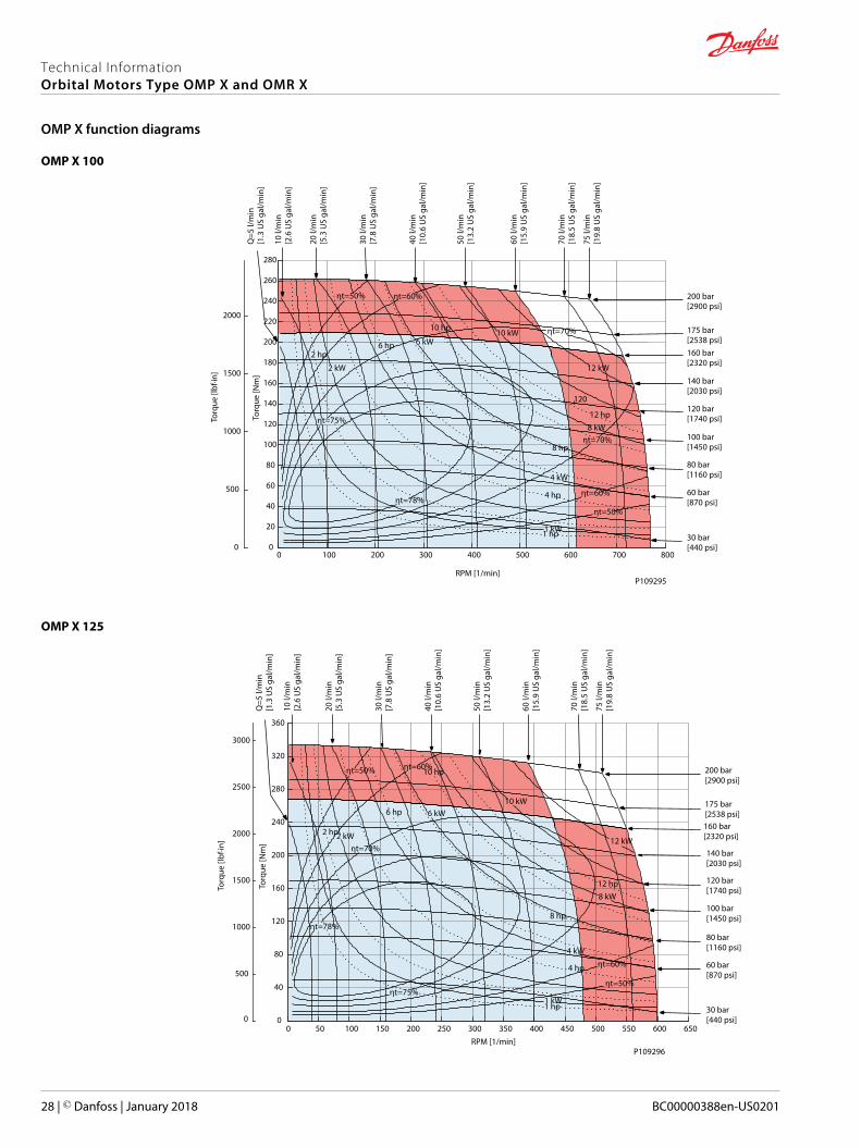
OMP X 100
P109295
0 100 200 300 400 500 600 700 800
RPM [1/min]
0
20
40
60
80
100
120
140
160
180
200
220
240
260
280To
rque
[Nm
]
120
0
500
1000
1500
2000
Torq
ue [l
bf·in
]
Q=5
l/m
in[1
.3 U
S ga
l/min
]
10 l/
min
[2.6
US
gal/m
in]
20 l/
min
[5.3
US
gal/m
in]
30 l/
min
[7.8
US
gal/m
in]
40 l/
min
[10.
6 U
S ga
l/min
]
50 l/
min
[13.
2 U
S ga
l/min
]
60 l/
min
[15.
9 U
S ga
l/min
]
70 l/
min
[18.
5 U
S ga
l/min
]
75 l/
min
[19.
8 U
S ga
l/min
]
160 bar[2320 psi]
100 bar[1450 psi]
80 bar[1160 psi]
60 bar[870 psi]
30 bar[440 psi]
200 bar[2900 psi]
175 bar[2538 psi]
140 bar[2030 psi]
120 bar[1740 psi]
12 kW
10 kW
8 kW
6 kW
4 kW
2 kW
1 kW
12 hp
10 hp
8 hp
6 hp
4 hp
2 hp
1 hp
ηt=50% ηt=60%
ηt=70%
ηt=75%
ηt=78%
ηt=70%
ηt=60%
ηt=50%
OMP X 125
P109296
0 50 100 150 200 250 300 350 400 450 500 550 600 650
RPM [1/min]
0
40
80
120
160
200
240
280
320
360
Torq
ue [N
m]
0
500
1000
1500
2000
2500
3000
Torq
ue [l
bf·in
]
Q=5
l/m
in[1
.3 U
S ga
l/min
]
10 l/
min
[2.6
US
gal/m
in]
20 l/
min
[5.3
US
gal/m
in]
30 l/
min
[7.8
US
gal/m
in]
40 l/
min
[10.
6 U
S ga
l/min
]
50 l/
min
[13.
2 U
S ga
l/min
]
60 l/
min
[15.
9 U
S ga
l/min
]
70 l/
min
[18.
5 U
S ga
l/min
]
75 l/
min
[19.
8 U
S ga
l/min
]
160 bar[2320 psi]
100 bar[1450 psi]
80 bar[1160 psi]
60 bar[870 psi]
30 bar[440 psi]
200 bar[2900 psi]
175 bar[2538 psi]
140 bar[2030 psi]
120 bar[1740 psi]
12 kW
10 kW
8 kW
6 kW
4 kW
2 kW
1 kW
12 hp
10 hp
8 hp
6 hp
4 hp
2 hp
1 hp
ηt=50% ηt=60%
ηt=70%
ηt=78%
ηt=75%ηt=50%
ηt=60%
Technical InformationOrbital Motors Type OMP X and OMR X
OMP X function diagrams
28 | © Danfoss | January 2018 BC00000388en-US0201

OMP X 160
0 50 100 150 200 250 300 350 400 450 500
RPM [1/min]
0
40
80
120
160
200
240
280
320
360
400
440
Torq
ue [N
m]
0
500
1000
1500
2000
2500
3000
3500
Torq
ue [l
bf·in
]
Q=5
l/m
in[1
.3 U
S ga
l/min
]
10 l/
min
[2.6
US
gal/m
in]
20 l/
min
[5.3
US
gal/m
in]
30 l/
min
[7.8
US
gal/m
in]
40 l/
min
[10.
6 U
S ga
l/min
]
50 l/
min
[13.
2 U
S ga
l/min
]
60 l/
min
[15.
9 U
S ga
l/min
]
70 l/
min
[18.
5 U
S ga
l/min
]
75 l/
min
[19.
8 U
S ga
l/min
]
160 bar[2320 psi]
100 bar[1450 psi]
80 bar[1160 psi]
60 bar[870 psi]
200 bar[2900 psi]
175 bar[2538 psi]
140 bar[2030 psi]
120 bar[1740 psi]
30 bar[440 psi]
12 kW
10 kW
8 kW
6 kW
4 kW
2 kW
1 kW
12 hp
10 hp
8 hp
6 hp
4 hp
2 hp
1 hp
ηt=50% ηt=60%
ηt=70%
ηt=78%
ηt=75% ηt=50%
ηt=60%
P109297
OMP X 200
0 50 100 150 200 250 300 350 400RPM [1/min]
0
50
100
150
200
250
300
350
400
450
500
550
Torq
ue [N
m]
1 hp
0
500
1000
1500
2000
2500
3000
3500
4000
4500
Torq
ue [l
bf·in
]
Q=5
l/m
in[1
.3 U
S ga
l/min
]
10 l/
min
[2.6
US
gal/m
in]
20 l/
min
[5.3
US
gal/m
in]
30 l/
min
[7.8
US
gal/m
in]
40 l/
min
[10.
6 U
S ga
l/min
]
50 l/
min
[13.
2 U
S ga
l/min
]
60 l/
min
[15.
9 U
S ga
l/min
]
70 l/
min
[18.
5 U
S ga
l/min
]
75 l/
min
[19.
8 U
S ga
l/min
]
155 bar[2248 psi]
100 bar[1450 psi]
80 bar[1160 psi]
60 bar[870 psi]
195 bar[2828 psi]
180 bar[2610 psi]
140 bar[2030 psi]
120 bar[1740 psi]
30 bar[440 psi]
12 kW
10 kW
8 kW
6 kW
4 kW
2 kW
1 kW
12 hp
10 hp
8 hp
6 hp
4 hp
2 hp
ηt=50% ηt=60%
ηt=70%
ηt=78%
ηt=75%ηt=50%
ηt=60%
P109298
Technical InformationOrbital Motors Type OMP X and OMR X
OMP X function diagrams
© Danfoss | January 2018 BC00000388en-US0201 | 29

OMP X 250
0 25 50 75 100 125 150 175 200 225 250 275 300 325
RPM [1/min]
0
80
160
240
320
400
480
560To
rque
[Nm
]
4 kW
1 hp
2 hp
4 hp
6 hp
10 hp
0
500
1000
1500
2000
2500
3000
3500
4000
4500
Torq
ue [l
bf·in
]
Q=5
l/m
in[1
.3 U
S ga
l/min
]
10 l/
min
[2.6
US
gal/m
in]
20 l/
min
[5.3
US
gal/m
in]
30 l/
min
[7.8
US
gal/m
in]
40 l/
min
[10.
6 U
S ga
l/min
]
50 l/
min
[13.
2 U
S ga
l/min
]
60 l/
min
[15.
9 U
S ga
l/min
]
70 l/
min
[18.
5 U
S ga
l/min
]
75 l/
min
[19.
8 U
S ga
l/min
]
155 bar[2248 psi]
100 bar[1450 psi]
85 bar[1232 psi]
60 bar[870 psi]
140 bar[2030 psi]
120 bar[1740 psi]
30 bar[440 psi]
12 kW10 kW
8 kW
6 kW
2 kW
1 kW
12 hp
8 hp
ηt=50% ηt=60%
ηt=70%
ηt=78%
ηt=75%ηt=50%
ηt=60%
P109299
OMP X 315
0 25 50 75 100 125 150 175 200 225 250
RPM [1/min]
0
50
100
150
200
250
300
350
400
450
500
Torq
ue [N
m]
1 kW
2 kW
1 hp
2 hp
6 hp
8 hp
10 hp
12 hp
0
500
1000
1500
2000
2500
3000
3500
4000
Torq
ue [l
bf·in
]
Q=5
l/m
in[1
.3 U
S ga
l/min
]
10 l/
min
[2.6
US
gal/m
in]
20 l/
min
[5.3
US
gal/m
in]
30 l/
min
[7.8
US
gal/m
in]
40 l/
min
[10.
6 U
S ga
l/min
]
50 l/
min
[13.
2 U
S ga
l/min
]
60 l/
min
[15.
9 U
S ga
l/min
]
70 l/
min
[18.
5 U
S ga
l/min
]
75 l/
min
[19.
8 U
S ga
l/min
]
100 bar[1450 psi]
85 bar[1232 psi]
50 bar[725 psi]
125 bar[1812 psi]
30 bar[440 psi]
70 bar[1015 psi]
8 kW
6 kW
4 kW
4 hp
ηt=50%ηt=60%
ηt=70%
ηt=78%
ηt=75%
ηt=50%
ηt=60%
P109300
Technical InformationOrbital Motors Type OMP X and OMR X
OMP X function diagrams
30 | © Danfoss | January 2018 BC00000388en-US0201

OMP X 400
P109301
0 25 50 75 100 125 150 175 200
RPM [1/min]
0
50
100
150
200
250
300
350
400
450
500
550
Torq
ue [N
m]
1 kW
2 kW
6 kW
1 hp
2 hp
4 hp
6 hp
8 hp
0
500
1000
1500
2000
2500
3000
3500
4000
4500
Torq
ue [l
bf·in
]
Q=5
l/m
in[1
.3 U
S ga
l/min
]
10 l/
min
[2.6
US
gal/m
in]
20 l/
min
[5.3
US
gal/m
in]
30 l/
min
[7.8
US
gal/m
in]
40 l/
min
[10.
6 U
S ga
l/min
]
50 l/
min
[13.
2 U
S ga
l/min
]
60 l/
min
[15.
9 U
S ga
l/min
]
70 l/
min
[18.
5 U
S ga
l/min
]
75 l/
min
[19.
8 U
S ga
l/min
]
75 bar[1087 psi]
65 bar[942 psi]
45 bar[652 psi]
95 bar[1377 psi]
30 bar[440 psi]
55 bar[797 psi]
4 kW
ηt=50%ηt=60% ηt=70%
ηt=70%
ηt=78%ηt=50%
ηt=60%
ηt=75%
Technical InformationOrbital Motors Type OMP X and OMR X
OMP X function diagrams
© Danfoss | January 2018 BC00000388en-US0201 | 31

OMP X and OMR X shaft versions
Cylindrical shaft 25 mm; Parallel key DIN 6885
max. 6 [0.24]
A-A
8.0 [0.315]
28.0
[1.1
02]
45°
[0.02]A
A
Ø28
.56[
1.12
4]
Ø25
.002
[.984
]6.4 [0.252]32.0 [1.260]
min. 18 [0.71]
43.8 [1.724]
M8
Ø25
.015
[.985
]
4.4 [0.173]31.7 [1.248]
42.5 [1.673]
R 0.5
27.7
[1.0
9]
7.964 [0.314]151-1842.12_A
Parallel key A8 • 7 • 32 DIN 6885
Max. cont. torque: 340 N•m [3010 lb•in]; Max. int. torque 450 N•m [3980 lb•in]
Cylindrical shaft 1 in; Parallel key B.S. 46
Ø25
.38
[.999
]
5.5 [0.217]31.75 [1.250]
Ø25
.4 [1
.0]
31.45 [1.238] 3.5 [0.138]
28.1
9 [1
.110
]27
.93
[1.1
00]
6.35 [0.250]6.40 [0.252]
max. 6 [0.24]
A-A
45°
[0.02]A
A
Ø28
.56[
1.12
4]
min. 18 [0.71]
43.8 [1.724]
M8
42.5 [1.673]
R 0.5
151-1842.12_B
Parallel key ¼ • ¼ • 1 ¼ B.S. 46
Max. cont. torque: 340 N•m [3010 lb•in]; Max. int. torque 450 N•m [3980 lb•in]
Cylindrical shaft 1 in; Parallel key B.S. 46 (US version)
45°
14 [0.55]
40.8 [1.606]39.2 [1.543]
Ø28
.56
[1.1
24]
31.75 [1.250]31.45 [1.238] 3.5 [0.138]
5.5 [0.217]
Ø25
.4 [1
.0]
Ø25
.38
[0.9
99]
28.1
9 [1
.110
]27
.93
[1.1
00]
6.35 [0.250]6.40 [0.252]
A
A
A-A
¼-20 UNCR 0.5[0.02]
max. 6 [0.24]
Parallel key ¼ • ¼ • 1 ¼ inB.S. 46
151-1842.12_C
Max. cont. torque: 340 N•m [3010 lb•in]; Max. int. torque 450 N•m [3980 lb•in]
Technical InformationOrbital Motors Type OMP X and OMR X
OMP X shaft version
32 | © Danfoss | January 2018 BC00000388en-US0201

Cylindrical shaft 1 in; Cross hole 8 mm
135° ±5°
11.5 [0.453]10.9 [0.429]
45.54 [1.793]
Ø28
.55
[1.1
24]
Ø26
.44
[1.0
41]
Ø26
.48
[1.0
43]
Ø25
.38
[0.9
99]
Ø25
.40
[1.0
]
Ø28
.57
[1.1
25]
Ø8.07 [0.318]Ø7.93 [0.312]
A
AR 0.5[0.02]
Max. torque: 200 N•m [1770 lb•in]
Cylindrical shaft 1 in; Cross hole 10.3 mm
135° ±5°
16.05 [0.63]15.45 [0.61]
40.0 [1.57]
Ø28
.55
[1.1
24]
Ø26
.44
[1.0
41]
1/4
– 20
UN
C
Ø26
.48
[1.0
43]
Ø25
.38
[0.9
99]
Ø25
.40
[1.0
]
Ø28
.57
[1.1
25]
Ø10.38 [0.409]Ø10.24 [0.403]
A
AR 0.5[0.02]
Max. torque: 200 N•m [1770 lb•in]
Cylindrical shaft 1 in (US version); SAE J502
28.3
1 [1
.115
]28
.03
[1.1
04]
Ø28
.57
[1.1
25]
Ø28
.56
[1.1
24]
Ø25
.38
[0.9
9]
19 [0.75]6.38 [0.251]6.35 [0.250]
Ø25
.40
[1.0
]
18 [0.71]
39.3 [1.547]40.6 [1.598]
27º25º
14 [0.55]16 [0.63]
¼-20UNC
R 0.35 [0.014]R 0.65 [0.026]
A
A A-A
1
1 Woodruff key ¼ x 1 in SAE J502
Technical InformationOrbital Motors Type OMP X and OMR X
OMP X shaft version
© Danfoss | January 2018 BC00000388en-US0201 | 33
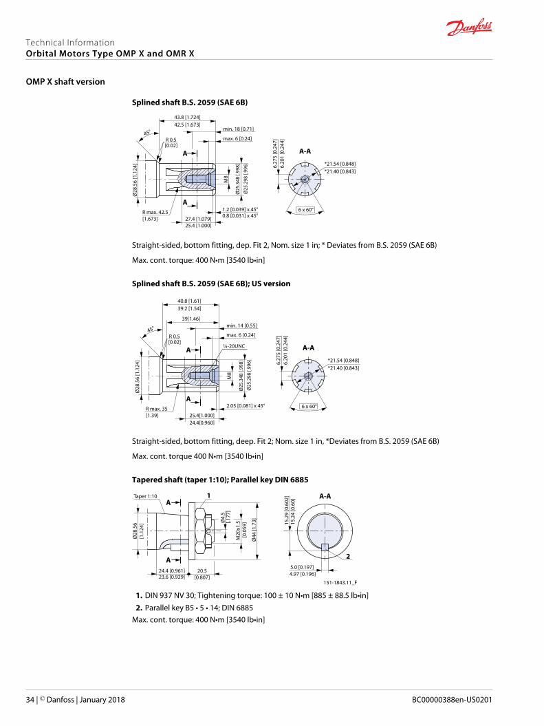
Splined shaft B.S. 2059 (SAE 6B)
R max. 42.5 [1.673]
Ø28
.56
[1.1
24]
Ø25
.298
[.99
6]
M8
1.2 [0.039] x 45°
27.4 [1.079]
45°
Ø25
.348
[.99
8]
0.8 [0.031] x 45°
25.4 [1.000]
42.5 [1.673]43.8 [1.724]
[0.02]R 0.5
A
A
6.20
1 [0
.244
] 6
.275
[0.2
47]
A-A
6 x 60°
*21.54 [0.848]*21.40 [0.843]
min. 18 [0.71]
max. 6 [0.24]
Straight-sided, bottom fitting, dep. Fit 2, Nom. size 1 in; * Deviates from B.S. 2059 (SAE 6B)
Max. cont. torque: 400 N•m [3540 lb•in]
Splined shaft B.S. 2059 (SAE 6B); US version
R max. 35 [1.39]
Ø28
.56
[1.1
24]
Ø25
.298
[.99
6]
M8
45°
Ø25
.348
[.99
8]
39.2 [1.54]40.8 [1.61]
39[1.46]
[0.02]R 0.5
A
A
6.20
1 [0
.244
] 6
.275
[0.2
47]
A-A
6 x 60°
*21.54 [0.848]*21.40 [0.843]
min. 14 [0.55]
max. 6 [0.24]
2.05 [0.081] x 45°
25.4[1.000]24.4[0.960]
¼-20UNC
Straight-sided, bottom fitting, deep. Fit 2; Nom. size 1 in, *Deviates from B.S. 2059 (SAE 6B)
Max. cont. torque 400 N•m [3540 lb•in]
Tapered shaft (taper 1:10); Parallel key DIN 6885
Taper 1:10
Ø4.
5 [.
177]
15.2
4 [0
.60]
5.0 [0.197]20.5
[0.807]24.4 [0.961]
Ø44
[1.7
3]
M20
x1.5
[0.0
59]
23.6 [0.929]
Ø28
.56
[1.1
24]
A
A
A-A
4.97 [0.196]
151-1843.11_F
15.2
9 [0
.602
]1
2
1. DIN 937 NV 30; Tightening torque: 100 ± 10 N•m [885 ± 88.5 lb•in]2. Parallel key B5 • 5 • 14; DIN 6885
Max. cont. torque: 400 N•m [3540 lb•in]
Technical InformationOrbital Motors Type OMP X and OMR X
OMP X shaft version
34 | © Danfoss | January 2018 BC00000388en-US0201
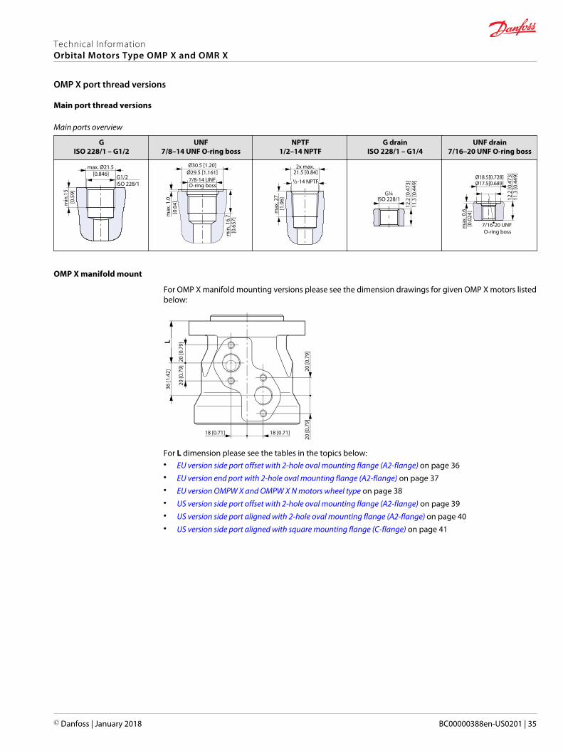
Main port thread versions
Main ports overview
GISO 228/1 – G1/2
UNF7/8–14 UNF O-ring boss
NPTF1/2–14 NPTF
G drainISO 228/1 – G1/4
UNF drain7/16–20 UNF O-ring boss
max. Ø21.5 [0.846]
min
.15
[0.5
9]
G1/2 ISO 228/1
min
. 16.
7 [0
.657
]
Ø30.5 [1.20]Ø29.5 [1.161]
max
. 1.0
[0.
04]
7/8-14 UNF O-ring boss
2x max. 21.5 [0.84]
max
. 27
[1.0
6]
½-14 NPTF
12.2
[0.4
73]
11.3
[0.4
49]
G¼ISO 228/1
max
. 0.6
[0.0
24]
Ø18.5[0.728]Ø17.5[0.689]
12.2
[0.4
73]
11.3
[0.4
49]
7/16-20 UNF O-ring boss
OMP X manifold mount
For OMP X manifold mounting versions please see the dimension drawings for given OMP X motors listedbelow:
18 [0.71] 18 [0.71]
20 [0
.79]
20 [0
.79]
20 [0
.79]
20 [0
.79]
36 [1
.42]
L
For L dimension please see the tables in the topics below:• EU version side port offset with 2-hole oval mounting flange (A2-flange) on page 36• EU version end port with 2-hole oval mounting flange (A2-flange) on page 37• EU version OMPW X and OMPW X N motors wheel type on page 38• US version side port offset with 2-hole oval mounting flange (A2-flange) on page 39• US version side port aligned with 2-hole oval mounting flange (A2-flange) on page 40• US version side port aligned with square mounting flange (C-flange) on page 41
Technical InformationOrbital Motors Type OMP X and OMR X
OMP X port thread versions
© Danfoss | January 2018 BC00000388en-US0201 | 35

EU version side port offset with 2-hole oval mounting flange (A2-flange)
74 [2.91]
38 [1.5]
max 80 [ 3.15]
8 [0.31]
16 [0.63]A
B
36 [1.42]
max Ø 931 [3.67]
Ø 82.55 [3.25]82.45 [3.246]
max 5.5 [0.22]
53.75 [2.116]
43.15 [1.7]
L max
Ø 13.55 [0.53]
106.4 [4.19]
max 103 [4.06]55 [2.17]
max 133.3 [5.25]
P109273
D
C
Port connections:
A, B Main ports: G 1/2; min 15 mm [0.59 in] deep
C Drain port: G 1/4; 11.5 mm [0.45 in]
D Thread: M8; 13 mm [0.51 in] deep
Size 25 32 40 50 60 80 100 125 160 200 250 315 400
Lmax.mm[in]
130.8[5.15]
131.9[5.22]
133.2[5.25]
133.2[5.25]
134.6[5.3]
137.1[5.4]
139.7[5.5]
143.4[5.65]
147.5[5.81]
152.7[6.02]
159.2[6.27]
167.6[6.6]
178.7[7.04]
Technical InformationOrbital Motors Type OMP X and OMR X
OMP X dimensions
36 | © Danfoss | January 2018 BC00000388en-US0201

EU version end port with 2-hole oval mounting flange (A2-flange)
8 [0.31]
16 [0.63]
36 [1.42]
max Ø 93.1 [3.67]
74 [2.91]
38 [1.5]
A
62.4 [2.46]
max 80 [3.15]
max 100 [3.394]
7.1 [0.28]
BC
Ø82.55 [3.25]82.45 [3.246]
7.5 [0.30]
L max
53.75 [2.116]
43.15 [1.7]
Ø 13.55 [0.53]
max 133.3 [5.25]
5 [0.2]55 [2.17]
max 103 [4.06]
106.4 [4.19]
P109275
D
Port connections:
A, B Main ports: G 1/2; min 15 mm [0.59 in] deep
C Drain port: G 1/4; 12 mm [0.47 in] deep
D Thread: M8; 13 mm [0.51 in] deep
Size 40 50 80 100 160 200 250 315 400
L max.mm [in]
146.8[5.78]
146.8[5.78]
150.7[5.94]
153.3[6.04]
161.1[6.35]
166.3[6.55]
172.8[6.81]
181.2[7.14]
192.2[7.58]
Technical InformationOrbital Motors Type OMP X and OMR X
OMP X dimensions
© Danfoss | January 2018 BC00000388en-US0201 | 37

EU version OMPW X and OMPW X N motors wheel type
max. 81 [3.19]
C
43.15 [1.7]
113.5 [4.47]
L max
max 5.5 [0.22]
max 102 [4.02]D
53 [2.09]
max 108 [4.25]
E
Ø 103 [4.06]Ø 65 [2.56]
Ø 86 [3.39]
37 [1.46]
20 [0.79]
67.75 [2.667]
80 [3.15]79.954 [3.148]
79.2 [3.12]78.8 [3.1]
7.25 [0.29]
A
B
P109267
Ø
Ø
Port connections:
A, B Main ports: G 1/2; min 15 mm [0.59 in] deep
C Drain port: G 1/4; 12 mm [0.47 in] deep
D Thread: M10, 20 mm [0.78 in] deep
Size 50 80 100 125 160 200 250 315 400
L max.mm [in]
73.4[2.89]
77.3[3.05]
79.9[3.15]
83.7[3.30]
87.7[3.46]
92.9[3.66]
99.4[3.92]
107.8[4.25]
118.9[4.69]
Technical InformationOrbital Motors Type OMP X and OMR X
OMP X dimensions
38 | © Danfoss | January 2018 BC00000388en-US0201

US version side port offset with 2-hole oval mounting flange (A2-flange)
max 80 [3.15]
82.55 [3.25]82.45 [3.246]
Ø
max 5.5 [0.22]
L max
40 [1.57]
45.2 [1.78]
Ø 13.55 [0.53]
max 133.3 [5.25]106.4 [4.19]
55 [2.17]
max 103 [4.06]
C
max Ø 93.1 [3.67]
36 [1.42]
BD
2.14 [0.84]A
2.6 [0.1]
79.4 [3.13]
43.3 [1.71]
P109277
Port connections:
A, B Main ports: 7/8 - 14 UNF; min. 16.7 mm [0.66 in] deep
C Drain port: 7/16 - 20 UNF; 11.5 mm [0.45 in] deep
D Thread: M8; 13 mm [0.51 in] deep
Size 25 32 40 50 80 100 160 200 315 400
L max.mm [in]
136.2[5.37]
137.3[5.41]
138.6[5.46]
138.6[5.46]
142.5[5.62]
145.1[5.72]
152.9[6.02]
158.1[6.82]
173.0[6.82]
184.1[7.25]
Technical InformationOrbital Motors Type OMP X and OMR X
OMP X dimensions
© Danfoss | January 2018 BC00000388en-US0201 | 39

US version side port aligned with 2-hole oval mounting flange (A2-flange)
max 84 [3.31]
C
Ø 89 [3.504]88.7 [34.92]
Ø 82.55 [3.25]82.45 [3.246]
max 5.5 [0.22]
L max
2.05 [0.081]
max 47.2 [1.86]
40 [1.57]
Ø 13.55 [0.53]
max 99 [3.9]
44.6 [1.76]
106.4 [4.19]
max 133.3 [5.25]
max Ø 93 [3.66]
45.7 [1.8]
B
15.5 [0.61]A
26 [0.10]
44 [1.73]
P109282
Port connections:
A, B Main ports: 7/8 - 14 UNF; min. 16.7 mm [0.66 in] deep
C Drain port: 7/16 - 20 UNF; 11.5 mm [0.45 in] deep
Size 36 50 80 100 125 160 200 250 315 400
L max.mm [in]
137.9[5.43]
138.6[5.46]
142.5[5.62]
145.1[5.72]
148.8[5.86]
152.9[6.02]
158.1[6.23]
164.6[6.49]
173[6.82]
184.1[7.25]
Technical InformationOrbital Motors Type OMP X and OMR X
OMP X dimensions
40 | © Danfoss | January 2018 BC00000388en-US0201

US version side port aligned with square mounting flange (C-flange)
max 84 [3.31]
C
max 5.5 [0.22]
L max
max 45.2 [1.78]
40 [1.57]
Ø 82.55 [3.25]
44.6 [1.76]
D
max 84 [3.31]
max Ø 93 [3.66]
45.7 [1.8]
B
A44 [1.73]
2.6 [0.10]
Ø 44.4 [1.75]
P109283
Port connections:
A, B Main ports: 7/8 - 14 UNF; min. 11.5 mm [0.45 in] deep
C Drain port: 7/16 - 20 UNF; 11.5 mm [0.45 in] deep
D Thread: 3/8 - 16 UNC; 15 mm [0.59 in] deep
Size 36 50 80 100 125 160 200 250 315 400
L max.mm [in]
137.9[5.43]
138.6[5.46]
142.5[5.62]
145.1[5.72]
148.8[5.86]
152.9[6.02]
158.1[6.23]
164.6[6.49]
173[6.82]
184.1[7.25]
Technical InformationOrbital Motors Type OMP X and OMR X
OMP X dimensions
© Danfoss | January 2018 BC00000388en-US0201 | 41

The following tables show the different versions configuration codes.• OMR X standard motors:
‒ Side port offset 2-hole oval mounting flange (A2 flange) on page 42
‒ Side port aligned with 2-hole oval mounting flange (A2 flange) on page 43
‒ Side port aligned with square mounting flange (C flange) on page 44
• OMR X N motors with needle bearings: Side port offset 2-hole oval mounting flange (A2-flange) on page45
If the desired OMR X could not be found please use the OMR X Model Code on page 46.
OMR X standard motors
For OMR X motors with a configuration which is not available in the code number tables please use themodel code number system in the OMR X Model Code on page 46 to specify the OMP X motor on detail.
Side port offset 2-hole oval mounting flange (A2 flange)
Configuration code numbers are set according to OMR X motor mounting flange type.
Configuration codes A1 – A7 description
Pilot dia. Ø 82.5 mm [3.25 in]
Bolt circledia.
Ø 106.4 mm [4.20 in]
Conf. code A2 A1 A3 A4 A5 A6 A7
Shaft Cyl. Ø25 mm Cyl. Ø25 mm Cyl. 1 in Cyl. 1 in Splined 1 in Splined 1 in Tap. Ø28.5mm
Main port G1/2 G1/2 G1/2 7/8 -14 UNF G1/2 7/8 -14 UNF G1/2
Drain port G1/4 G1/4 G1/4 7/16-20 UNF G1/4 7/16-20 UNF G1/4
Port type End Side offset
Check valve Yes
Shaft seal High pressure shaft seal
Designation Main type designation: OMR X
Code numbers for OMR X: A1 — A7
Code Displacement
50 80 100 125 160 200 250 315 375
A1 11185537 11186671 11186674 11186655 11186658 11186665 11186667 11186652 11185531
A2 11185473 11185474 11186645 11185468 11185469 11186642 11185471 11185467 11186644
A3 11185558 11185560 11185562 11185548 11185549 11185551 11185554 11185545 11185556
A4 11185488 11185489 11185490 11185483 11185484 11185485 11185486 11185482 11185487
A5 11185584 11185585 11185588 11185567 11185570 11185573 11185576 11185564 11185580
A6 11185497 11185498 11185499 11185492 11185493 11185494 11185495 11185491 11185496
A7 11185609 11185610 11185611 11185604 11185605 11185606 11185607 11185603 11185608
Technical InformationOrbital Motors Type OMP X and OMR X
OMR X configuration versions overview with codes numbers
42 | © Danfoss | January 2018 BC00000388en-US0201
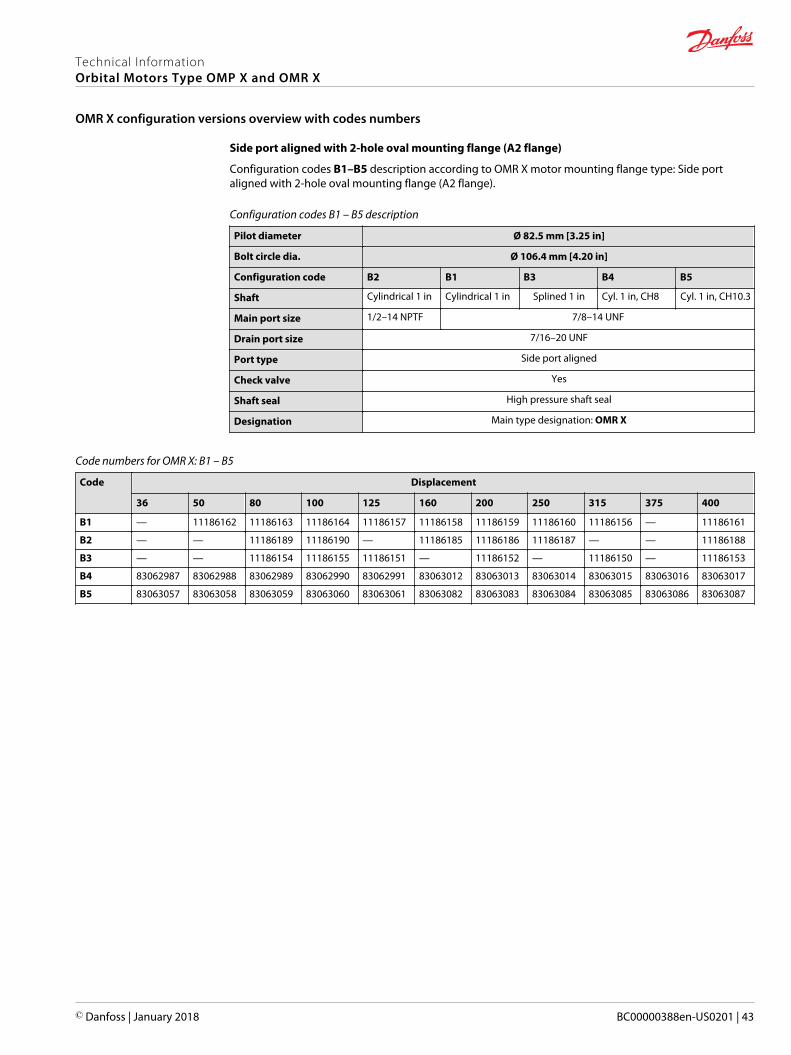
Side port aligned with 2-hole oval mounting flange (A2 flange)
Configuration codes B1–B5 description according to OMR X motor mounting flange type: Side portaligned with 2-hole oval mounting flange (A2 flange).
Configuration codes B1 – B5 description
Pilot diameter Ø 82.5 mm [3.25 in]
Bolt circle dia. Ø 106.4 mm [4.20 in]
Configuration code B2 B1 B3 B4 B5
Shaft Cylindrical 1 in Cylindrical 1 in Splined 1 in Cyl. 1 in, CH8 Cyl. 1 in, CH10.3
Main port size 1/2–14 NPTF 7/8–14 UNF
Drain port size 7/16–20 UNF
Port type Side port aligned
Check valve Yes
Shaft seal High pressure shaft seal
Designation Main type designation: OMR X
Code numbers for OMR X: B1 – B5
Code Displacement
36 50 80 100 125 160 200 250 315 375 400
B1 — 11186162 11186163 11186164 11186157 11186158 11186159 11186160 11186156 — 11186161
B2 — — 11186189 11186190 — 11186185 11186186 11186187 — — 11186188
B3 — — 11186154 11186155 11186151 — 11186152 — 11186150 — 11186153
B4 83062987 83062988 83062989 83062990 83062991 83063012 83063013 83063014 83063015 83063016 83063017
B5 83063057 83063058 83063059 83063060 83063061 83063082 83063083 83063084 83063085 83063086 83063087
Technical InformationOrbital Motors Type OMP X and OMR X
OMR X configuration versions overview with codes numbers
© Danfoss | January 2018 BC00000388en-US0201 | 43
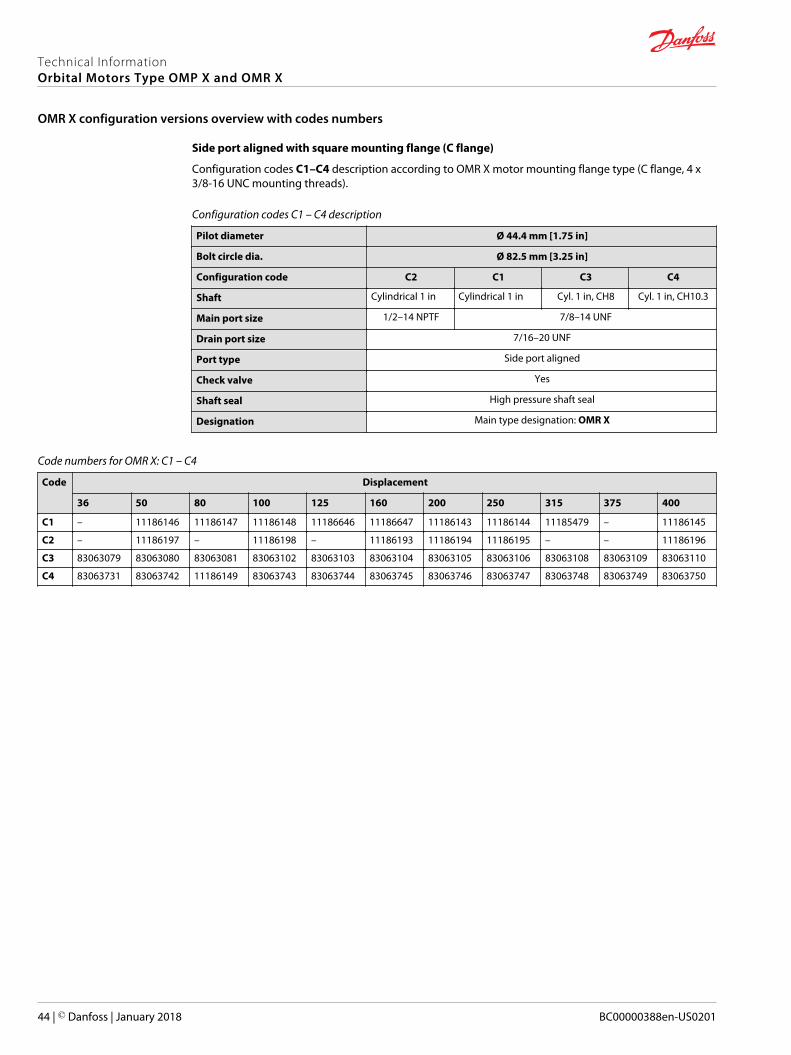
Side port aligned with square mounting flange (C flange)
Configuration codes C1–C4 description according to OMR X motor mounting flange type (C flange, 4 x3/8-16 UNC mounting threads).
Configuration codes C1 – C4 description
Pilot diameter Ø 44.4 mm [1.75 in]
Bolt circle dia. Ø 82.5 mm [3.25 in]
Configuration code C2 C1 C3 C4
Shaft Cylindrical 1 in Cylindrical 1 in Cyl. 1 in, CH8 Cyl. 1 in, CH10.3
Main port size 1/2–14 NPTF 7/8–14 UNF
Drain port size 7/16–20 UNF
Port type Side port aligned
Check valve Yes
Shaft seal High pressure shaft seal
Designation Main type designation: OMR X
Code numbers for OMR X: C1 – C4
Code Displacement
36 50 80 100 125 160 200 250 315 375 400
C1 – 11186146 11186147 11186148 11186646 11186647 11186143 11186144 11185479 – 11186145
C2 – 11186197 – 11186198 – 11186193 11186194 11186195 – – 11186196
C3 83063079 83063080 83063081 83063102 83063103 83063104 83063105 83063106 83063108 83063109 83063110
C4 83063731 83063742 11186149 83063743 83063744 83063745 83063746 83063747 83063748 83063749 83063750
Technical InformationOrbital Motors Type OMP X and OMR X
OMR X configuration versions overview with codes numbers
44 | © Danfoss | January 2018 BC00000388en-US0201
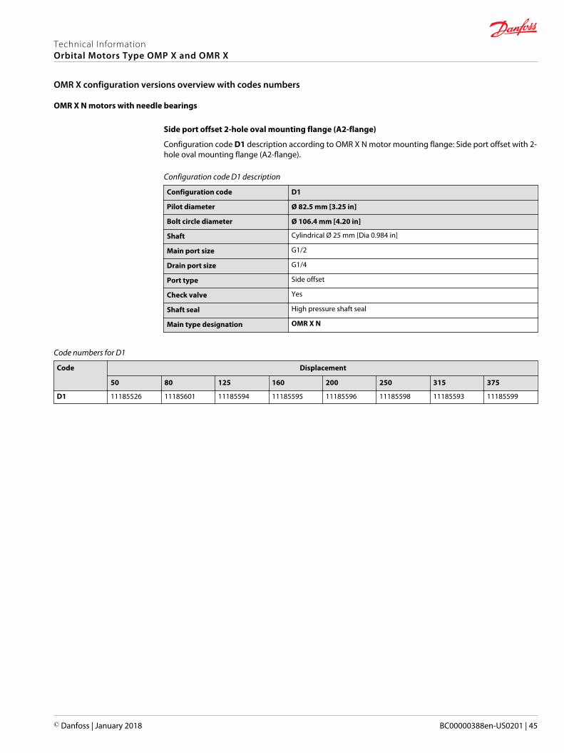
OMR X N motors with needle bearings
Side port offset 2-hole oval mounting flange (A2-flange)
Configuration code D1 description according to OMR X N motor mounting flange: Side port offset with 2-hole oval mounting flange (A2-flange).
Configuration code D1 description
Configuration code D1
Pilot diameter Ø 82.5 mm [3.25 in]
Bolt circle diameter Ø 106.4 mm [4.20 in]
Shaft Cylindrical Ø 25 mm [Dia 0.984 in]
Main port size G1/2
Drain port size G1/4
Port type Side offset
Check valve Yes
Shaft seal High pressure shaft seal
Main type designation OMR X N
Code numbers for D1
Code Displacement
50 80 125 160 200 250 315 375
D1 11185526 11185601 11185594 11185595 11185596 11185598 11185593 11185599
Technical InformationOrbital Motors Type OMP X and OMR X
OMR X configuration versions overview with codes numbers
© Danfoss | January 2018 BC00000388en-US0201 | 45

The coding system has been developed to identify the configuration options for the OMP X motors. Themodel code begins with the motor family and the remaining fields are filled in to configure the motorwith the desired features, all fields must be filled in. Example: OMRX-200-NNN-B11-SO-A3-A11-C-E-B-1-N-N-NN-NNN-NNN-NNN-A-NN.
B C D FE K M N SRPA
A
G H
C 1 N
J
N N N N N N
T
N N
L U V
A – Main motor family
OMRX OMR X motor series
B – Motor displacement
Code Displacement, cm3/rev [ in3/rev]
036 36.9 [2.25]
050 51.6 [3.15]
080 80.3 [4.90]
100 99.8 [6.09]
125 124.1 [7.57]
160 155.4 [9.48]
200 198.2 [12.09]
250 248.1 [15.14]
315 310.1 [18.92]
375 363.5 [22.18]
400 390.7 [23.84]
C – Motor type (Align with options: D, E and F)
Code Description
NNN Standard motor
B13 Standard motor with needle bearing
D – Mounting type (Align with options: E and F)
Code Description
B11 A2 flange; 82.5 Dia x 8 Pilot; 106.4 Dia B.C.
B12 A2 flange; 82.5 Dia x 2.6 Pilot; 106.4 Dia B.C.
C10 C4 flange; 44 Dia x 2.6 Pilot; 83 Dia B.C.; 3/8-16 mounting
E – Port type (Align with options: D, F and G)
Code Description
SO Side port – Offset
SA Side port – Aligned
EA End port
Technical InformationOrbital Motors Type OMP X and OMR X
OMR X Model Code
46 | © Danfoss | January 2018 BC00000388en-US0201

Example: OMRX-200-NNN-B11-SO-A3-A11-C-E-B-1-N-N-NN-NNN-NNN-NNN-A-NN.
B C D FE K M N SRPAA
G H
C 1 N
J
N N N N N N
T
N N
L U V
F – Main ports thread type
Code Description
A3 G 1/2
A8 7/8-14 UNF
A9 1/2-14 NPTF
B7 M22 x 1,5 according to ISO 6149
C1 Manifold
G – Shaft type (Align with options: C, F and K)
Code Description
A11 Cylindrical 25 mm with 8 mm key; M8 hole in shaft end
B11 Cylindrical 1 inch with 1/4 in key; M8 hole in shaft end
B12 Cylindrical 1 inch with 1/4 in key; 1/4-20UNC hole in shaft end
B13 Cylindrical 1 inch with Woodruff key; 1/4-20UNC hole in shaft end
B14 Cylindrical 1 inch with cross hole 10.3; 1/4-20UNC hole in shaft end
B15 Cylindrical 1 inch with cross hole 8.0
C11 Spline 7/8" – 13T
C13 1 inch 6B Spline; M8 hole in shaft end
C14 1 inch 6B Spline; 1/4-20UNC hole in shaft end
E10 Tapered 28.5 mm – 1:10
F10 Tapered 1" – 1:8, WK3/16x3/4
H – Shaft seal
C High pressure shaft seal - NBR
J – Dust seal
Code Description
B Dust seal integrated in shaft seal plus seal guard
E Dust seal integrated in shaft seal
K – Drain port (Align with options: F and G)
Code Description
B G1/4
D 7/16 – 20 UNF
K M12 x 1,5 according to ISO 6149
M No drain port due to EMD
Technical InformationOrbital Motors Type OMP X and OMR X
OMR X Model Code
© Danfoss | January 2018 BC00000388en-US0201 | 47

Example: OMRX-200-NNN-B11-SO-A3-A11-C-E-B-1-N-N-NN-NNN-NNN-NNN-A-NN.
B C D FE K M N SRPAA
G HC 1 N
JN N N N N N
T
N N
L U V
A
L – Check Valve
1 Yes
M – Brake release port
N None
N – Speed sensor
N None
A Prepared for EMD speed sensor
P – Painting
Code Description
NN No paint
AA Black, 9005; Corr. class C3; Standard covering
AB Black, 9005; Corr. class C3; Surface covering
R – Valve option
NNN None
S – Specific visible features
NNN None
T – Specific non-visible features
NNN None
U – Packaging
A Single pack
V – Name tags: Motor and box
NN Danfoss name tag
Technical InformationOrbital Motors Type OMP X and OMR X
OMR X Model Code
48 | © Danfoss | January 2018 BC00000388en-US0201

OMR X motor specification
OMR X motors, sizes: 50 – 160 cm³
Description Unit 50 80 100 125 160
Geometric displacement cm³ [in] 51.6 [3.16] 80.3 [4.91] 99.8 [6.11] 124.1 [7.57] 155.4 [9.48]
Max. speed cont. min-1 (rpm) 775 750 600 475 385
int.2) 970 940 750 600 480
Max. torque1) cont. N•m [lb•in] 100 [890] 215 [1900] 275 [2435] 330 [2920] 380 [3365]
int.2) 120 [1060] 235 [2080] 300 [2655] 360 [3185] 435 [3580]
Max. output cont. kW [hp] 7.0 [9.4] 14.0 [18.8] 14.0 [18.8] 14.0 [18.8] 12.6 [16.9]
int.2) 8.8 [11.7] 15.8 [21.1] 17.5 [23.5] 17.5 [23.5] 15.8 [21.1]
Max. pressure drop cont. bar [psi] 150 [2175] 200 [2900] 200 [2900] 200 [2900] 180 [2610]
int.2) 175 [2540] 225 [3260] 225 [3260] 225 [3260] 215 [3120]
Max. starting pressure withunloaded shaft
bar [psi] 10 [145] 10 [145] 10 [145] 10 [145] 10 [145]
Max. oil flow cont. l/min[US gal/min]
40 [10.6] 60 [15.9] 60 [15.9] 60 [15.9] 60 [15.9]
int.2) 50 [13.2] 75 [19.8] 75 [19.8] 75 [19.8] 75 [19.8]
Min starting torqueat max. pressuredrop
cont. N•m [lb•in] 85 [750] 190 [1680] 230 [2035] 295 [2610] 335 [2965]
int.2) 100 [890] 215 [1900] 255 [2255] 335 [2965] 400 [3540]
OMR X motors, sizes: 200 – 400 cm³
Description Unit 200 250 315 375 400
Geometric displacement cm³ [in] 198.2 [12.09] 248.1 [15.14] 310.1 [18.92] 363.5 [22.18] 390.7 [23.84]
Max. speed cont. min-1 (rpm) 305 240 195 165 155
int.2) 380 300 245 205 195
Max. torque1) cont. N•m [lb•in] 400 [3540] 400 [3540] 400 [3540] 390 [3450] 400 [3540]
int.2) 480 [4250] 540 [4780] 550 [4870] 550 [4870] 480 [4250]
Max. output cont. kW [hp] 10.5 [14] 8.8 [11.7] 7.0 [9.4] 5.6 [7.5] 4.9 [6.6]
int.2) 13.1 [17.5] 10.5 [14.1] 8.9 [11.9] .8 [10.5] 6.1 [8.2]
Max. pressure drop cont. bar [psi] 150 [2175] 125 [1815] 100 [1450] 80 [1160] 70 [1015]
int.2) 195 [2830] 170 [2465] 140 [2030] 115 [1670] 90 [1305]
Max. starting pressure withunloaded shaft
bar [psi] 10 [145] 7 [100] 7 [100] 7 [100] 5 [75]
Max. oil flow cont. l/min[US gal/min]
60 [15.9] 60 [15.9] 60 [15.9] 60 [15.9] 60 [15.9]
int.2) 75 [19.8] 75 [19.8] 75 [19.8] 75 [19.8] 75 [19.8]
Min starting torqueat max. pressuredrop
cont. N•m [lb•in] 350 [3100] 370 [3275] 370 [3275] 335 [2965] 325 [2875]
int.2) 460 [4070] 500 [4425] 515 [4560] 480 [4250] 420 [3715]
1) Maximum torque values for the different output shafts can be found in OMP X shaft version on page 32.2) Intermittent operation: the permissible values may occur for max. 10% of every minute.
Pressure limits
Description All sizes
Max. inlet pressure drop Continuous 200 bar [2900 psi]
Intermittent 225 bar [3260 psi]
Max. return pressure with drain line Continuous 200 bar [2900 psi]
Intermittent 225 bar [3260 psi]
Technical InformationOrbital Motors Type OMP X and OMR X
OMR X technical data
© Danfoss | January 2018 BC00000388en-US0201 | 49

High Pressure Shaft Seal in OMP X and OMR X motors
OMP X and OMR X motors feature options with High Pressure Shaft Seal (HPS), with check valves and withor without drain connection.
HPS pressure in the drain connection
OMP X/OMR X with drain connection OMP X/OMR X without drain connection
The shaft seal pressure equals the pressure in the drainline
The shaft seal pressure never exceeds the pressure inthe return line
151-320.10
Maximum permissible shaft seal pressure
psi
3600
3000
2400
1800
1200
600
0
bar
250
200
150
100
50
00 100 200 300 400 500 600 700 800 1600
intermittent operation
Ø25 mm-Ø1”-Ø1” splined shaft
min-1 (rpm)
Pressure drop in OMR X motor
The curve applies to an unloaded motor shaft and an oil viscosity of 35 mm2/s [165 SUS]
psi
400
350
300
250
200
150
100
50
0
bar30
25
20
15
10
5
00 10 20 30 40 50 60 70 80 l/min
0 2 4 6 8 10 12 14 16 18 20 US gal/min
151-1566.10
Q
Q
pp
Technical InformationOrbital Motors Type OMP X and OMR X
OMR X technical data
50 | © Danfoss | January 2018 BC00000388en-US0201
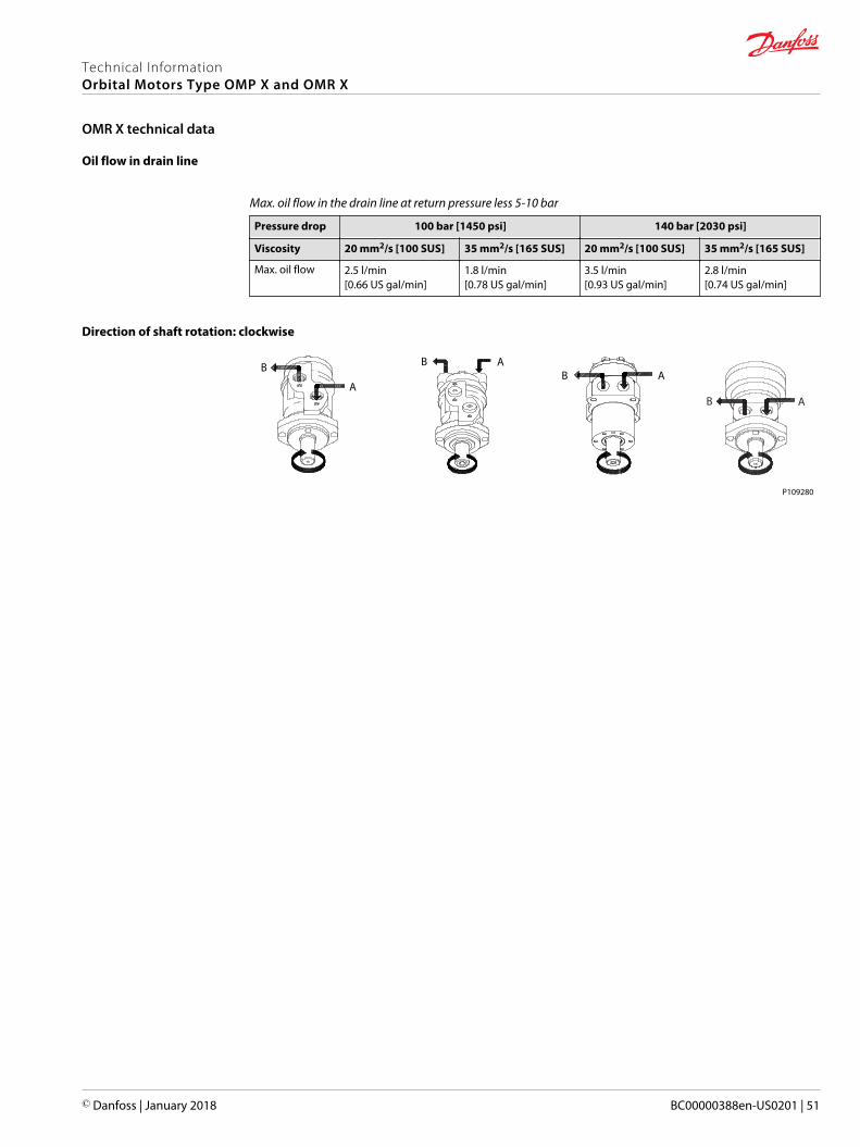
Oil flow in drain line
Max. oil flow in the drain line at return pressure less 5-10 bar
Pressure drop 100 bar [1450 psi] 140 bar [2030 psi]
Viscosity 20 mm2/s [100 SUS] 35 mm2/s [165 SUS] 20 mm2/s [100 SUS] 35 mm2/s [165 SUS]
Max. oil flow 2.5 l/min[0.66 US gal/min]
1.8 l/min[0.78 US gal/min]
3.5 l/min[0.93 US gal/min]
2.8 l/min[0.74 US gal/min]
Direction of shaft rotation: clockwise
A
B B AB A
P109280
AB
Technical InformationOrbital Motors Type OMP X and OMR X
OMR X technical data
© Danfoss | January 2018 BC00000388en-US0201 | 51
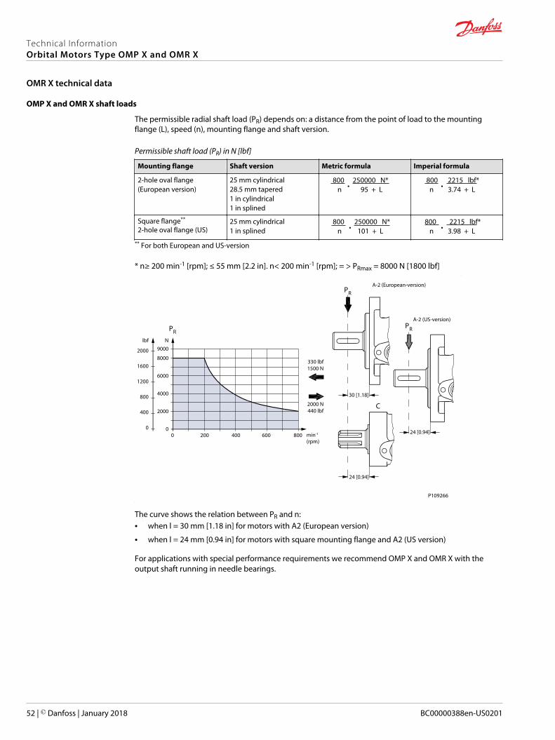
OMP X and OMR X shaft loads
The permissible radial shaft load (PR) depends on: a distance from the point of load to the mountingflange (L), speed (n), mounting flange and shaft version.
Permissible shaft load (PR) in N [lbf]
Mounting flange Shaft version Metric formula Imperial formula
2-hole oval flange(European version)
25 mm cylindrical28.5 mm tapered1 in cylindrical1 in splined
800 • 250000 N*
n 95 + L 800
• 2215 lbf*
n 3.74 + L
Square flange**
2-hole oval flange (US)25 mm cylindrical1 in splined
800 • 250000 N*
n 101 + L 800
• 2215 lbf*
n 3.98 + L
** For both European and US-version
* n≥ 200 min-1 [rpm]; ≤ 55 mm [2.2 in]. n< 200 min-1 [rpm]; = > PRmax = 8000 N [1800 lbf]
30 [1.18]
24 [0.94]
24 [0.94]
330 lbf1500 N
2000 N440 lbf
A-2 (European-version)
A-2 (US-version)
PR
PR
PR
C
lbf
2000
1600
1200
800
400
0
N9000
8000
6000
4000
2000
00 200 400 600 800 min-1
(rpm)
P109266
The curve shows the relation between PR and n:• when l = 30 mm [1.18 in] for motors with A2 (European version)
• when l = 24 mm [0.94 in] for motors with square mounting flange and A2 (US version)
For applications with special performance requirements we recommend OMP X and OMR X with theoutput shaft running in needle bearings.
Technical InformationOrbital Motors Type OMP X and OMR X
OMR X technical data
52 | © Danfoss | January 2018 BC00000388en-US0201

OMR X N with needle bearings shaft loads
4400
4000
3600
3200
2800
2400
2000
1600
1200
800
400
0
20000
18000
16000
14000
12000
10000
8000
6000
4000
2000
0
151-2112.10
120 110 100 90 80 70 60 50 40 30 20 10 0 -10 -20 -30 mm
4 3 2 1 0 -1 in
lbf NPrad. Prad.
Pmax.
Pmax.
=
=
2000 N450 lbf
1500 N335 lbf
0 -
50 min-1
200 min-1
800 min-1
A
+
The output shaft on OMR X N runs in needle bearings. These bearings and the recessed mounting flangeallow a higher permissible radial load in comparison to OMR X motors with slide bearings.
The permissible radial load on the shaft is shown for different speeds as a function of the distance fromthe mounting flange to the point of load application.
Curve A indicates the max. radial shaft load. Any shaft load exceeding the values quoted in curve A willinvolve risk of breakage.
The other curves apply to a B10 bearing life of 2000 hours at the number of revolutions indicated by thecurve letter. Mineral based hydraulic oil with a sufficient content of anti-wear additives must be used.
Bearing life calculations can be made using the explanation and formula provided in the chapter "Bearingdimensioning" in the technical information General Orbital Motors, BC00000083.
Technical InformationOrbital Motors Type OMP X and OMR X
OMR X technical data
© Danfoss | January 2018 BC00000388en-US0201 | 53

Performance graphs for OMR X motors according to the displacement. Blue area shows continuous rangeand red area shows intermittent range (max. 10% operation every minute).
Explanation of function diagram use, basis and conditions can be found in Operating ParametersDiagrams on page 7.
Intermittent pressure drop and oil flow must not occur simultaneously. Max. permissible continuous/intermittent pressure drop for the actual shaft version can be found in OMR X technical data on page 49.
OMR X 50
0 200 400 600 800 1000 1200
RPM [1/min]
0
20
40
60
80
100
120
Torq
ue [N
m]
1 kW
2 kW
4 kW
6 kW
8 kW
10 kW
1 hp
2 hp
4 hp
6 hp
8 hp
10 hp
12 hp
0
100
200
300
400
500
600
700
800
900
1000
Torq
ue [l
bf·in
]
Q=5
l/m
in[1
.3 U
S ga
l/min
]
10 l/
min
[2.6
US
gal/m
in]
20 l/
min
[5.3
US
gal/m
in]
30 l/
min
[7.8
US
gal/m
in]
40 l/
min
[10.
6 U
S ga
l/min
]
50 l/
min
[13.
2 U
S ga
l/min
]
15 l/
min
[3.9
6 U
S ga
l/min
]
25 l/
min
[6.6
US
gal/m
in]
35 l/
min
[9.2
US
gal/m
in]
45 l/
min
[11.
9 U
S ga
l/min
]100 bar[1450 psi]
80 bar[1160 psi]
60 bar[870 psi]
30 bar[440 psi]
175 bar[2538 psi]
140 bar[2030 psi]
120 bar[1740 psi]
150 bar[2175 psi]
ηt=50%ηt=70%
ηt=75%
ηt=78%
ηt=50%ηt=60%
P109302
Technical InformationOrbital Motors Type OMP X and OMR X
OMR X function diagrams
54 | © Danfoss | January 2018 BC00000388en-US0201

OMR X 80
0 100 200 300 400 500 600 700 800 900 1000RPM [1/min]
0
20
40
60
80
100
120
140
160
180
200
220
240
260
Torq
ue [N
m]
1 kW
2 kW
4 kW
6 kW
8 kW
10 kW
12 kW
1 hp
2 hp
4 hp
6 hp
8 hp
10 hp
12 hp
0
500
1000
1500
2000
Torq
ue [l
bf·in
]
Q=5
l/m
in[1
.3 U
S ga
l/min
]
10 l/
min
[2.6
US
gal/m
in]
20 l/
min
[5.3
US
gal/m
in]
30 l/
min
[7.8
US
gal/m
in]
40 l/
min
[10.
6 U
S ga
l/min
]
50 l/
min
[13.
2 U
S ga
l/min
]
60 l/
min
[15.
9 U
S ga
l/min
]
70 l/
min
[18.
5 U
S ga
l/min
]
75 l/
min
[19.
8 U
S ga
l/min
]
160 bar[2320 psi]
100 bar[1450 psi]
80 bar[1160 psi]
60 bar[870 psi]
30 bar[440 psi]
200 bar[2900 psi]
180 bar[2610 psi]
140 bar[2030 psi]
120 bar[1740 psi]
225 bar[3263 psi]
ηt=60%
ηt=75% ηt=70%
ηt=50%
P109303
OMR X 100
P109304
0 100 200 300 400 500 600 700 800
RPM [1/min]
0
40
80
120
160
200
240
280
320
Torq
ue [N
m]
1 kW
2 kW
4 kW
6 kW
8 kW
10 kW
12 kW
1 hp
2 hp
4 hp
6 hp
8 hp
10 hp
12 hp
0
500
1000
1500
2000
2500
Torq
ue [l
bf·in
]
Q=5
l/m
in[1
.3 U
S ga
l/min
]
10 l/
min
[2.6
US
gal/m
in]
20 l/
min
[5.3
US
gal/m
in]
30 l/
min
[7.8
US
gal/m
in]
40 l/
min
[10.
6 U
S ga
l/min
]
50 l/
min
[13.
2 U
S ga
l/min
]
60 l/
min
[15.
9 U
S ga
l/min
]
70 l/
min
[18.
5 U
S ga
l/min
]
75 l/
min
[19.
8 U
S ga
l/min
]
100 bar[1450 psi]
80 bar[1160 psi]
60 bar[870 psi]
30 bar[440 psi]
200 bar[2900 psi]
140 bar[2030 psi]
120 bar[1740 psi]
225 bar[3263 psi]
175 bar[2538 psi]
ηt=50%
ηt=70%
ηt=75%
ηt=80%
ηt=50%ηt=60%
Technical InformationOrbital Motors Type OMP X and OMR X
OMR X function diagrams
© Danfoss | January 2018 BC00000388en-US0201 | 55

OMR X 125
P109305
0 50 100 150 200 250 300 350 400 450 500 550 600 650
RPM [1/min]
0
40
80
120
160
200
240
280
320
360
400To
rque
[Nm
]
1 kW
2 kW
4 kW
6 kW
8 kW
10 kW
12 kW
1 hp
2 kW
4 kW
6 hp
8 hp
10 hp
12 hp
0
500
1000
1500
2000
2500
3000
3500
Torq
ue [l
bf·in
]
Q=5
l/m
in[1
.3 U
S ga
l/min
]
10 l/
min
[2.6
US
gal/m
in]
20 l/
min
[5.3
US
gal/m
in]
30 l/
min
[7.8
US
gal/m
in]
40 l/
min
[10.
6 U
S ga
l/min
]
50 l/
min
[13.
2 U
S ga
l/min
]
60 l/
min
[15.
9 U
S ga
l/min
]
70 l/
min
[18.
5 U
S ga
l/min
]
75 l/
min
[19.
8 U
S ga
l/min
]
100 bar[1450 psi]
80 bar[1160 psi]
60 bar[870 psi]
30 bar[440 psi]
200 bar[2900 psi]
140 bar[2030 psi]
120 bar[1740 psi]
225 bar[3263 psi]
175 bar[2538 psi]
ηt=50%ηt=60%
ηt=80%
ηt=75%ηt=70% ηt=60%
ηt=50%
OMR X 160
P109306
0 50 100 150 200 250 300 350 400 450 500RPM [1/min]
0
40
80
120
160
200
240
280
320
360
400
440
480
Torq
ue [N
m]
215
1 kW
2 kW
4 kW
6 kW
8 kW
10 kW
12 kW
1 hp
2 hp
4 hp
6 hp
8 hp
10 hp
12 hp
0
500
1000
1500
2000
2500
3000
3500
4000
Torq
ue [l
bf·in
]
Q=5
l/m
in[1
.3 U
S ga
l/min
]
10 l/
min
[2.6
US
gal/m
in]
20 l/
min
[5.3
US
gal/m
in]
30 l/
min
[7.8
US
gal/m
in]
40 l/
min
[10.
6 U
S ga
l/min
]
50 l/
min
[13.
2 U
S ga
l/min
]
60 l/
min
[15.
9 U
S ga
l/min
]
70 l/
min
[18.
5 U
S ga
l/min
]
75 l/
min
[19.
8 U
S ga
l/min
]
215 bar[3118 psi]
180 bar[2610 psi]
160 bar[2320 psi]
100 bar[1450 psi]
80 bar[1160 psi]
60 bar[870 psi]
30 bar[440 psi]
140 bar[2030 psi]
120 bar[1740 psi]
ηt=50%
ηt=70%
ηt=75%
ηt=82%
ηt=80%
ηt=60%ηt=50%
Technical InformationOrbital Motors Type OMP X and OMR X
OMR X function diagrams
56 | © Danfoss | January 2018 BC00000388en-US0201

OMR X 200
P109307
0 50 100 150 200 250 300 350 400RPM [1/min]
0
50
100
150
200
250
300
350
400
450
500
Torq
ue [N
m]
1 kW
2 kW
4 kW
6 kW
8 kW
10 kW
12 kW
1 hp
2 hp
4 hp
6 hp
8 hp
10 hp
12 hp
0
500
1000
1500
2000
2500
3000
3500
4000
Torq
ue [l
bf·in
]
Q=5
l/m
in[1
.3 U
S ga
l/min
]
10 l/
min
[2.6
US
gal/m
in]
20 l/
min
[5.3
US
gal/m
in]
30 l/
min
[7.8
US
gal/m
in]
40 l/
min
[10.
6 U
S ga
l/min
]
50 l/
min
[13.
2 U
S ga
l/min
]
60 l/
min
[15.
9 U
S ga
l/min
]
70 l/
min
[18.
5 U
S ga
l/min
]
75 l/
min
[19.
8 U
S ga
l/min
]
195 bar[2828 psi]
150 bar[2175 psi]
100 bar[1450 psi]
80 bar[1160 psi]
60 bar[870 psi]
30 bar[440 psi]
120 bar[1740 psi]
ηt=50% ηt=60%
ηt=70%
ηt=80%ηt=83%
ηt=82%ηt=75%
ηt=50%
ηt=60%
OMR X 250
P109308
0 25 50 75 100 125 150 175 200 225 250 275 300 325RPM [1/min]
0
50
100
150
200
250
300
350
400
450
500
550
Torq
ue [N
m]
1 kW
2 kW
4 kW
6 kW
8 kW
10 kW12 kW
1 hp
2 hp
4 hp
6 hp
8 hp
10 hp
12 hp
0
500
1000
1500
2000
2500
3000
3500
4000
4500
Torq
ue [l
bf·in
]
Q=5
l/m
in[1
.3 U
S ga
l/min
]
10 l/
min
[2.6
US
gal/m
in]
20 l/
min
[5.3
US
gal/m
in]
30 l/
min
[7.8
US
gal/m
in]
40 l/
min
[10.
6 U
S ga
l/min
]
50 l/
min
[13.
2 U
S ga
l/min
]
60 l/
min
[15.
9 U
S ga
l/min
]
70 l/
min
[18.
5 U
S ga
l/min
]
75 l/
min
[19.
8 U
S ga
l/min
]
170 bar[2465 psi]
150 bar[2175 psi]
100 bar[1450 psi]
80 bar[1160 psi]
60 bar[870 psi]
30 bar[440 psi]
125 bar[1812 psi]
ηt=50% ηt=60%
ηt=60%
ηt=75%
ηt=82%
ηt=83%ηt=80%
ηt=70%
ηt=50%
ηt=60%
Technical InformationOrbital Motors Type OMP X and OMR X
OMR X function diagrams
© Danfoss | January 2018 BC00000388en-US0201 | 57

OMR X 315
P109309
0 25 50 75 100 125 150 175 200 225 250
RPM [1/min]
0
50
100
150
200
250
300
350
400
450
500
550
600To
rque
[Nm
]
1 kW
2 kW
4 kW
6 kW
8 kW
10 kW
1 hp
2 hp
4 hp
6 hp
8 hp
10 hp
12 hp
0
500
1000
1500
2000
2500
3000
3500
4000
4500
5000
Torq
ue [l
bf·in
]
Q=5
l/m
in[1
.3 U
S ga
l/min
]
10 l/
min
[2.6
US
gal/m
in]
20 l/
min
[5.3
US
gal/m
in]
30 l/
min
[7.8
US
gal/m
in]
40 l/
min
[10.
6 U
S ga
l/min
]
50 l/
min
[13.
2 U
S ga
l/min
]
60 l/
min
[15.
9 U
S ga
l/min
]
70 l/
min
[18.
5 U
S ga
l/min
]
75 l/
min
[19.
8 U
S ga
l/min
]
100 bar[1450 psi]
80 bar[1160 psi]
60 bar[870 psi]
30 bar[440 psi]
140 bar[2030 psi]
120 bar[1740 psi]
ηt=50%
ηt=75%
ηt=70%
ηt=50%
ηt=60%
OMR X 375
P109310
0 25 50 75 100 125 150 175 200 225RPM [1/min]
0
50
100
150
200
250
300
350
400
450
500
550
600
Torq
ue [N
m]
115
1 kW
2 kW
4 kW
6 kW
8 kW
1 hp
2 hp
4 hp
6 hp
8 hp
10 hp
12 hp
0
500
1000
1500
2000
2500
3000
3500
4000
4500
5000
Torq
ue [l
bf·in
]
Q=5
l/m
in[1
.3 U
S ga
l/min
]
10 l/
min
[2.6
US
gal/m
in]
20 l/
min
[5.3
US
gal/m
in]
30 l/
min
[7.8
US
gal/m
in]
40 l/
min
[10.
6 U
S ga
l/min
]
50 l/
min
[13.
2 U
S ga
l/min
]
60 l/
min
[15.
9 U
S ga
l/min
]
70 l/
min
[18.
5 U
S ga
l/min
]
75 l/
min
[19.
8 U
S ga
l/min
]
80 bar[1160 psi]
60 bar[870 psi]
30 bar[440 psi]
115 bar[1667 psi]
ηt=50%ηt=60%
ηt=80%
ηt=82%
ηt=75%
ηt=50%
ηt=60%
ηt=70%
Technical InformationOrbital Motors Type OMP X and OMR X
OMR X function diagrams
58 | © Danfoss | January 2018 BC00000388en-US0201

OMR X 400
OMR X 400
00
50
100
150
200
250
300
350
400
450
500
Torq
ue (N
•m)
Torq
ue [l
b•in
]
70 bar[1015 psi]
60 bar[870 psi]
30 bar[435 psi]
45 bar[653 psi]
90 bar[1305 psi]
25 50 75 100 125 150 175 200min-1 (rpm)
0
500
1000
1500
2000
2500
3000
3500
4000
Q =
5 l/
min
[1.3
US
gal/m
in]
Q =
10
l/min
[2.6
US
gal/m
in]
Q =
20
l/min
[5.3
US
gal/m
in]
Q =
30
l/min
[7.8
US
gal/m
in]
Q =
40
l/min
[10.
6 U
S ga
l/min
]
Q =
50
l/min
[13.
2 U
S ga
l/min
]
Q =
60
l/min
[15.
9 U
S ga
l/min
]
Q =
70
l/min
[18.
5 U
S ga
l/min
]
Q =
75
l/min
[19.
8 U
S ga
l/min
]
ηt=80%
ηt=82% ηt=75%
ηt=50%
ηt=60%
ηt=70%
Technical InformationOrbital Motors Type OMP X and OMR X
OMR X function diagrams
© Danfoss | January 2018 BC00000388en-US0201 | 59

OMP X and OMR X shaft versions
Cylindrical shaft 25 mm; Parallel key DIN 6885
max. 6 [0.24]
A-A
8.0 [0.315]
28.0
[1.1
02]
45°
[0.02]A
A
Ø28
.56[
1.12
4]
Ø25
.002
[.984
]6.4 [0.252]32.0 [1.260]
min. 18 [0.71]
43.8 [1.724]
M8
Ø25
.015
[.985
]
4.4 [0.173]31.7 [1.248]
42.5 [1.673]
R 0.5
27.7
[1.0
9]
7.964 [0.314]151-1842.12_A
Parallel key A8 • 7 • 32 DIN 6885
Max. cont. torque: 340 N•m [3010 lb•in]; Max. int. torque 450 N•m [3980 lb•in]
Cylindrical shaft 1 in; Parallel key B.S. 46
Ø25
.38
[.999
]
5.5 [0.217]31.75 [1.250]
Ø25
.4 [1
.0]
31.45 [1.238] 3.5 [0.138]
28.1
9 [1
.110
]27
.93
[1.1
00]
6.35 [0.250]6.40 [0.252]
max. 6 [0.24]
A-A
45°
[0.02]A
A
Ø28
.56[
1.12
4]
min. 18 [0.71]
43.8 [1.724]
M8
42.5 [1.673]
R 0.5
151-1842.12_B
Parallel key ¼ • ¼ • 1 ¼ B.S. 46
Max. cont. torque: 340 N•m [3010 lb•in]; Max. int. torque 450 N•m [3980 lb•in]
Cylindrical shaft 1 in; Parallel key B.S. 46 (US version)
45°
14 [0.55]
40.8 [1.606]39.2 [1.543]
Ø28
.56
[1.1
24]
31.75 [1.250]31.45 [1.238] 3.5 [0.138]
5.5 [0.217]
Ø25
.4 [1
.0]
Ø25
.38
[0.9
99]
28.1
9 [1
.110
]27
.93
[1.1
00]
6.35 [0.250]6.40 [0.252]
A
A
A-A
¼-20 UNCR 0.5[0.02]
max. 6 [0.24]
Parallel key ¼ • ¼ • 1 ¼ inB.S. 46
151-1842.12_C
Max. cont. torque: 340 N•m [3010 lb•in]; Max. int. torque 450 N•m [3980 lb•in]
Technical InformationOrbital Motors Type OMP X and OMR X
OMR X Shaft version
60 | © Danfoss | January 2018 BC00000388en-US0201

Cylindrical shaft 1 in; Cross hole 8 mm
135° ±5°
11.5 [0.453]10.9 [0.429]
45.54 [1.793]
Ø28
.55
[1.1
24]
Ø26
.44
[1.0
41]
Ø26
.48
[1.0
43]
Ø25
.38
[0.9
99]
Ø25
.40
[1.0
]
Ø28
.57
[1.1
25]
Ø8.07 [0.318]Ø7.93 [0.312]
A
AR 0.5[0.02]
Max. torque: 200 N•m [1770 lb•in]
Cylindrical shaft 1 in; Cross hole 10.3 mm
135° ±5°
16.05 [0.63]15.45 [0.61]
40.0 [1.57]
Ø28
.55
[1.1
24]
Ø26
.44
[1.0
41]
1/4
– 20
UN
C
Ø26
.48
[1.0
43]
Ø25
.38
[0.9
99]
Ø25
.40
[1.0
]
Ø28
.57
[1.1
25]
Ø10.38 [0.409]Ø10.24 [0.403]
A
AR 0.5[0.02]
Max. torque: 200 N•m [1770 lb•in]
Cylindrical shaft 1 in (US version); SAE J502
28.3
1 [1
.115
]28
.03
[1.1
04]
Ø28
.57
[1.1
25]
Ø28
.56
[1.1
24]
Ø25
.38
[0.9
9]
19 [0.75]6.38 [0.251]6.35 [0.250]
Ø25
.40
[1.0
]
18 [0.71]
39.3 [1.547]40.6 [1.598]
27º25º
14 [0.55]16 [0.63]
¼-20UNC
R 0.35 [0.014]R 0.65 [0.026]
A
A A-A
1
1 Woodruff key ¼ x 1 in SAE J502
Technical InformationOrbital Motors Type OMP X and OMR X
OMR X Shaft version
© Danfoss | January 2018 BC00000388en-US0201 | 61

Splined shaft B.S. 2059 (SAE 6B)
R max. 42.5 [1.673]
Ø28
.56
[1.1
24]
Ø25
.298
[.99
6]
M8
1.2 [0.039] x 45°
27.4 [1.079]
45°
Ø25
.348
[.99
8]
0.8 [0.031] x 45°
25.4 [1.000]
42.5 [1.673]43.8 [1.724]
[0.02]R 0.5
A
A
6.20
1 [0
.244
] 6
.275
[0.2
47]
A-A
6 x 60°
*21.54 [0.848]*21.40 [0.843]
min. 18 [0.71]
max. 6 [0.24]
Straight-sided, bottom fitting, dep. Fit 2, Nom. size 1 in; * Deviates from B.S. 2059 (SAE 6B)
Max. cont. torque: 400 N•m [3540 lb•in]
Splined shaft B.S. 2059 (SAE 6B); US version
R max. 35 [1.39]
Ø28
.56
[1.1
24]
Ø25
.298
[.99
6]
M8
45°
Ø25
.348
[.99
8]
39.2 [1.54]40.8 [1.61]
39[1.46]
[0.02]R 0.5
A
A
6.20
1 [0
.244
] 6
.275
[0.2
47]
A-A
6 x 60°
*21.54 [0.848]*21.40 [0.843]
min. 14 [0.55]
max. 6 [0.24]
2.05 [0.081] x 45°
25.4[1.000]24.4[0.960]
¼-20UNC
Straight-sided, bottom fitting, deep. Fit 2; Nom. size 1 in, *Deviates from B.S. 2059 (SAE 6B)
Max. cont. torque 400 N•m [3540 lb•in]
Tapered shaft (taper 1:10); Parallel key DIN 6885
Taper 1:10
Ø4.
5 [.
177]
15.2
4 [0
.60]
5.0 [0.197]20.5
[0.807]24.4 [0.961]
Ø44
[1.7
3]
M20
x1.5
[0.0
59]
23.6 [0.929]
Ø28
.56
[1.1
24]
A
A
A-A
4.97 [0.196]
151-1843.11_F
15.2
9 [0
.602
]1
2
1. DIN 937 NV 30; Tightening torque: 100 ± 10 N•m [885 ± 88.5 lb•in]2. Parallel key B5 • 5 • 14; DIN 6885
Max. cont. torque: 400 N•m [3540 lb•in]
Technical InformationOrbital Motors Type OMP X and OMR X
OMR X Shaft version
62 | © Danfoss | January 2018 BC00000388en-US0201

Main port thread versions
Main ports overview
GISO 228/1 – G1/2
UNF7/8–14 UNF O-ring boss
NPTF1/2–14 NPTF
G drainISO 228/1 – G1/4
UNF drain7/16–20 UNF O-ring boss
max. Ø21.5 [0.846]
min
.15
[0.5
9]
G1/2 ISO 228/1
min
. 16.
7 [0
.657
]
Ø30.5 [1.20]Ø29.5 [1.161]
max
. 1.0
[0.
04]
7/8-14 UNF O-ring boss
2x max. 21.5 [0.84]
max
. 27
[1.0
6]
½-14 NPTF
12.2
[0.4
73]
11.3
[0.4
49]
G¼ISO 228/1
max
. 0.6
[0.0
24]
Ø18.5[0.728]Ø17.5[0.689]
12.2
[0.4
73]
11.3
[0.4
49]
7/16-20 UNF O-ring boss
OMR X manifold mount
For OMR X manifold mounting versions please see the dimension drawings for given OMR X motors listedbelow:
18 [0.71] 18 [0.71]
20 [0
.79]
20 [0
.79]
20 [0
.79]
20 [0
.79]
36 [1
.42]
L
For L dimension please see the tables in the topics below:• EU version side port offset with 2-hole oval mounting flange (A2-flange) on page 64• EU version end port version with 2-hole oval mounting flange (A2-flange) on page 65• US version side port offset with 2-hole oval mounting flange (A2-flange) on page 66• US version side port aligned with 2 hole oval mounting flange (A2) on page 67• US version side port aligned with square mounting flange (C-flange) on page 68
Technical InformationOrbital Motors Type OMP X and OMR X
OMR X port thread versions
© Danfoss | January 2018 BC00000388en-US0201 | 63

EU version side port offset with 2-hole oval mounting flange (A2-flange)
max 110 [4.33]
max 80 [3.15]
C
max 5.5 [0.22]
L max
max 55.75 [2.195]
43.15 [1.7]
Ø82.55 [3.250]82.45 [3.246]
Ø 13.55 [0.553]
max 133.3 [5.25]106.4 [4.19]
55 [2.17]
max 103 [4.06]
max Ø 107.3 [4.22]
36 [1.42]
B
A16 [0.63]
8 [0.31]
38 [1.5]
74 [2.91]
D
P109285
Port connections:
A, B Main ports: G 1/2; min 15 mm [0.59 in] deep
C Drain port: G 1/4; 12 mm [0.47 in] deep
Size 50 80 100 125 160 200 250 315 375 400
L max.mm [in]
137.8[5.43]
142.8[5.63]
142.8[5.63]
146.2[5.76]
150.6[5.93]
156.6[6.17]
163.6[6.45]
172.3[6.79]
179.8[7.08]
183.6[7.23]
Technical InformationOrbital Motors Type OMP X and OMR X
OMR X dimensions
64 | © Danfoss | January 2018 BC00000388en-US0201

EU version end port version with 2-hole oval mounting flange (A2-flange)
max 110 [4.33]
20 [0.78]
25 [0.99]
max 80 [3.15]
31.2 [1.23]
5 [0.2]60.5 [2.38]59.5 [2.34]7.1 [0.28]
max 115 [4.53]
B
C
A
Ø82.55 [3.250]82.45 [3.246]
7.5 [0.3]
L max
43.15 [1.70]
53.75 [2.12]
Ø 13.55 [0.53]
max 133.3 [5.25]
55 [2.17]
max 103 [4.06]
106.4 [4.19]
max Ø 107.3 [4.22]
36 [1.42]
D
38 [1.5]
74 [2.91]
8 [0.315]
16 [0.631]
P109287
Port connections:
A, B Main ports: G 1/2; min 15 mm [0.59 in] deep
C Drain port: G 1/4; 12 mm [0.47 in] deep
D Thread: M8; 13 mm [0.51 in] deep
Size 50 80 100 125 160 200 250 315 375
L max.mm [in]
150.3[5.82]
155.3[6.12]
155.3[6.12]
158.7[6.25]
163.1[6.43]
169.1[6.66]
176.1[6.94]
184.6[7.28]
192.3[7.58]
Technical InformationOrbital Motors Type OMP X and OMR X
OMR X dimensions
© Danfoss | January 2018 BC00000388en-US0201 | 65
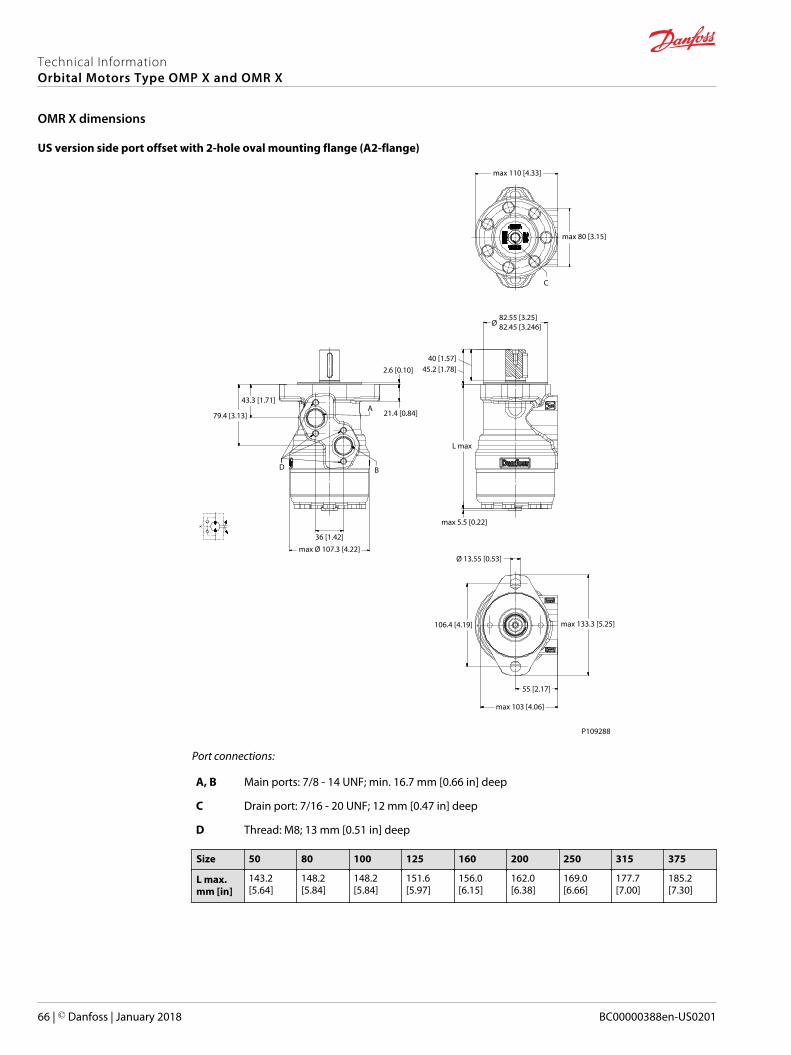
US version side port offset with 2-hole oval mounting flange (A2-flange)
max 110 [4.33]
max 80 [3.15]
C
Ø82.55 [3.25]82.45 [3.246]
max 5.5 [0.22]
L max
40 [1.57]45.2 [1.78]
Ø 13.55 [0.53]
max 133.3 [5.25]
55 [2.17]
max 103 [4.06]
106.4 [4.19]
max Ø 107.3 [4.22]
36 [1.42]
BD
79.4 [3.13]
43.3 [1.71]A
21.4 [0.84]
2.6 [0.10]
P109288
Port connections:
A, B Main ports: 7/8 - 14 UNF; min. 16.7 mm [0.66 in] deep
C Drain port: 7/16 - 20 UNF; 12 mm [0.47 in] deep
D Thread: M8; 13 mm [0.51 in] deep
Size 50 80 100 125 160 200 250 315 375
L max.mm [in]
143.2[5.64]
148.2[5.84]
148.2[5.84]
151.6[5.97]
156.0[6.15]
162.0[6.38]
169.0[6.66]
177.7[7.00]
185.2[7.30]
Technical InformationOrbital Motors Type OMP X and OMR X
OMR X dimensions
66 | © Danfoss | January 2018 BC00000388en-US0201

US version side port aligned with 2 hole oval mounting flange (A2)
Max. 84 [3.31]
C
40 [1.57]
Max 47.2 [1.96]2.6 [0.1]
15.5 [0.61]
L max
2.05 [0.081]
Max 5.5 [0.22]
A
B
44 [2.73]
Max Ø 107 [4.21]
45.7 [1.8]
Ø 13.55 [0.53]
Max 133.3 [5.35]106.4 [4.19]
44.6 [1.76]
P109445
Port connections:
A, B Main ports: 7/8 - 14 UNF; min. 16.7 mm [0.66 in] deep
C Drain port: 7/16 - 20 UNF; 12 mm [0.47 in] deep
Size 50 80 100 125 160 200 250 315 375 400
L max.mm [in]
137.8[5.43]
142.8[5.63]
142.8[5.63]
146.2[5.76]
150.6[5.93]
156.6[6.17]
163.6[6.45]
172.3[6.79]
179.8[7.08]
183.6[7.23]
Technical InformationOrbital Motors Type OMP X and OMR X
OMR X dimensions
© Danfoss | January 2018 BC00000388en-US0201 | 67
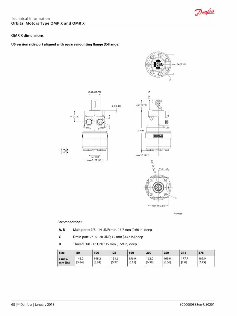
US version side port aligned with square mounting flange (C-flange)
max 84 [3.31]
C
max 5.5 [0.22]
L max
45.2 [1.78]
40 [1.57]Ø
82.55 [3.25]
44.6 [1.76]
D
max 84 [3.31]
max Ø 107 [4.21]45.7 [1.8]
44 [1.73]
Ø 44.4 [1.75]
2.6 [0.10]
A
B
P109289
Port connections:
A, B Main ports: 7/8 - 14 UNF; min. 16.7 mm [0.66 in] deep
C Drain port: 7/16 - 20 UNF; 12 mm [0.47 in] deep
D Thread: 3/8 - 16 UNC; 15 mm [0.59 in] deep
Size 80 100 125 160 200 250 315 375
L max.mm [in]
148.2[5.84]
148.2[5.84]
151.6[5.97]
156.0[6.15]
162.0[6.38]
169.0[6.66]
177.7[7.0]
189.0[7.45]
Technical InformationOrbital Motors Type OMP X and OMR X
OMR X dimensions
68 | © Danfoss | January 2018 BC00000388en-US0201

Weight of OMP X and OMR X motors
The large table of OMP X and OMR X motors weight according to ordering code number (see in boldfont).
OMP X and OMR X weight
Code No. kg lb Code No. kg lb Code No. kg lb Code No. kg lb
11185412 8,1 17,9 11185632 7,6 16,7 11185874 5,6 12,4 11186173 7,2 15,9
11185460 8,4 18,4 11185633 9,1 20,1 11185875 5,8 12,7 11186174 7,5 16,6
11185461 8,7 19,1 11185634 7,5 16,6 11185876 6,1 13,4 11186175 6,8 15,0
11185462 9,0 19,9 11185635 6,3 13,9 11185877 5,9 13,1 11186176 7,1 15,6
11185463 9,9 21,7 11185636 7,8 17,2 11185878 7,0 15,5 11186177 7,4 16,3
11185464 7,7 16,9 11185637 8,8 19,3 11185879 5,6 12,4 11186178 7,9 17,5
11185465 7,9 17,5 11185638 7,6 16,8 11185880 6,1 13,4 11186179 8,3 18,2
11185466 7,9 17,5 11185639 7,2 15,9 11185881 5,9 13,1 11186180 9,3 20,5
11185467 9,5 20,9 11185640 9,5 21,0 11185882 6,3 13,9 11186181 7,2 15,8
11185468 8,1 17,9 11185641 8,4 18,6 11185883 6,5 14,4 11186183 8,7 19,3
11185469 8,4 18,4 11185642 9,9 21,8 11185884 6,8 14,9 11186184 9,3 20,6
11185470 8,7 19,1 11185643 8,0 17,6 11185885 7,1 15,7 11186185 7,6 16,8
11185471 9,0 19,9 11185644 9,5 21,0 11185886 7,5 16,6 11186186 7,9 17,5
11185472 9,9 21,7 11185645 9,1 20,0 11185887 5,6 12,4 11186187 8,3 18,3
11185473 7,7 16,9 11185648 8,7 19,1 11185888 5,7 12,6 11186188 9,3 20,6
11185474 7,9 17,5 11185649 7,3 16,1 11185889 5,7 12,6 11186189 7,2 15,9
11185475 7,9 17,5 11185650 7,3 16,1 11185890 5,8 12,9 11186190 7,2 15,9
11185476 8,7 19,1 11185651 7,5 16,6 11185891 6,1 13,5 11186191 7,2 16,0
11185477 7,9 17,5 11185672 7,8 17,3 11185892 6,0 13,2 11186192 7,2 15,9
11185478 7,5 16,5 11185673 8,2 18,1 11185893 6,3 13,8 11186193 7,3 16,2
11185479 8,4 18,6 11185674 6,8 15,1 11185894 6,5 14,2 11186194 7,7 16,9
11185480 7,1 15,6 11185675 6,8 15,1 11185895 6,7 14,8 11186195 8,0 17,7
11185481 7,3 16,1 11185676 7,1 15,7 11185896 6,1 13,4 11186196 9,1 20,0
11185482 8,7 19,3 11185677 8,7 19,1 11185897 6,3 13,8 11186197 6,6 14,7
11185483 7,4 16,3 11185678 7,5 16,6 11185898 6,5 14,2 11186198 6,9 15,3
11185484 7,6 16,8 11185679 7,1 15,7 11185899 6,7 14,8 11186199 6,9 15,2
11185485 7,9 17,5 11185703 7,2 15,9 11185900 6,1 13,4 11186611 8,4 18,4
11185486 8,3 18,3 11185704 7,0 15,5 11185902 6,2 13,6 11186642 8,7 19,1
11185487 9,1 20,1 11185705 7,2 15,9 11185903 6,4 14,0 11186643 8,7 19,1
11185488 6,9 15,2 11185706 7,5 16,5 11185904 7,5 16,6 11186644 9,9 21,7
11185489 7,2 15,8 11185707 7,8 17,2 11185905 5,7 12,5 11186645 7,9 17,5
11185490 7,2 15,9 11185708 8,2 18,2 11185906 5,7 12,6 11186646 7,1 15,6
11185491 8,7 19,2 11185710 6,4 14,1 11185907 5,9 13,1 11186647 7,3 16,1
11185492 7,4 16,3 11185711 6,4 14,1 11185908 6,0 13,3 11186648 8,7 19,2
11185493 7,6 16,8 11185713 6,6 14,5 11185909 6,9 15,3 11186649 7,4 16,3
11185494 7,9 17,5 11185714 6,7 14,8 11185910 6,3 14,0 11186650 8,3 18,2
11185495 8,3 18,2 11185715 6,4 14,2 11185911 6,5 14,4 11186651 6,9 15,2
11185496 9,1 20,1 11185716 6,6 14,6 11185912 7,3 16,1 11186652 8,7 19,1
11185497 6,9 15,2 11185717 6,9 15,2 11185913 7,3 16,1 11186653 8,7 19,1
11185498 7,2 15,8 11185718 7,2 15,9 11185914 7,9 17,4 11186655 7,3 16,1
11185499 7,2 15,9 11185719 7,6 16,8 11186040 6,0 13,3 11186657 7,3 16,1
Technical InformationOrbital Motors Type OMP X and OMR X
Weight of motors
© Danfoss | January 2018 BC00000388en-US0201 | 69

OMP X and OMR X weight (continued)
Code No. kg lb Code No. kg lb Code No. kg lb Code No. kg lb
11185500 7,9 17,5 11185720 5,7 12,6 11186041 5,3 11,7 11186658 7,5 16,6
11185501 8,7 19,3 11185721 5,8 12,8 11186042 6,6 14,6 11186659 7,5 16,6
11185502 7,4 16,3 11185722 5,8 12,8 11186043 5,7 12,5 11186660 7,5 16,6
11185503 7,6 16,8 11185723 5,8 12,8 11186044 5,8 12,9 11186662 7,5 16,6
11185504 7,9 17,5 11185724 6,0 13,2 11186046 6,0 13,3 11186664 7,5 16,6
11185505 8,3 18,3 11185725 6,3 13,8 11186047 6,3 13,9 11186665 7,8 17,3
11185506 9,1 20,1 11185726 6,1 13,5 11186049 6,6 14,6 11186667 8,2 18,1
11185507 6,9 15,3 11185727 5,8 12,8 11186050 6,6 14,6 11186670 6,8 15,1
11185508 7,2 15,9 11185728 6,4 14,2 11186052 7,0 15,5 11186671 7,1 15,7
11185509 7,2 15,9 11185729 6,9 15,1 11186054 5,2 11,5 11186673 7,1 15,7
11185510 6,8 15,1 11185730 5,7 12,6 11186056 5,2 11,6 11186674 7,1 15,7
11185511 7,1 15,7 11185731 5,8 12,8 11186057 5,4 12,0 11186675 7,1 15,7
11185512 7,1 15,7 11185732 6,3 13,8 11186059 5,5 12,2 11186677 7,5 16,6
11185513 8,7 19,1 11185733 6,4 14,2 11186060 5,2 11,5 11186680 7,1 15,7
11185514 8,7 19,1 11185734 6,6 14,6 11186061 5,4 11,9 11186681 7,1 15,7
11185515 7,5 16,6 11185735 7,2 15,9 11186062 5,5 12,2 11186682 7,5 16,6
11185516 8,7 19,1 11185736 6,9 15,2 11186063 5,5 12,2 11186684 6,8 15,1
11185517 7,3 16,1 11185737 5,8 12,8 11186064 6,1 13,5 11186685 7,8 17,3
11185518 7,3 16,1 11185738 6,0 13,2 11186065 6,3 13,9 11186686 7,5 16,6
11185519 7,3 16,1 11185739 6,1 13,5 11186066 6,5 14,4 11186687 7,0 15,5
11185520 7,5 16,6 11185740 5,7 12,5 11186067 6,9 15,2 11186688 7,5 16,5
11185521 7,1 15,7 11185742 5,8 12,7 11186068 7,3 16,1 11186691 5,7 12,5
11185522 7,5 16,6 11185743 6,2 13,6 11186069 5,5 12,1 11186692 5,8 12,9
11185523 7,5 16,6 11185745 6,2 13,6 11186071 5,5 12,1 11186693 5,4 12,0
11185524 7,5 16,6 11185746 6,2 13,6 11186072 5,7 12,5 11186694 6,1 13,5
11185525 7,8 17,3 11185748 6,3 14,0 11186073 5,8 12,8 11186695 5,7 12,6
11185526 6,8 15,0 11185749 6,4 14,0 11186074 5,6 12,3 11186696 5,8 12,8
11185527 7,9 17,3 11185750 6,3 14,0 11186075 5,9 13,1 11186697 6,4 14,2
11185528 8,2 18,1 11185751 6,5 14,4 11186076 6,1 13,5 11186698 6,6 14,6
11185530 8,2 18,1 11185752 6,6 14,4 11186077 6,3 13,9 11186699 5,8 12,7
11185531 9,0 19,9 11185753 6,6 14,4 11186079 6,6 14,5 11186702 6,2 13,6
11185533 9,0 19,9 11185755 6,5 14,4 11186081 6,9 15,2 11186705 6,3 14,0
11185534 9,0 19,9 11185756 6,6 14,4 11186083 7,3 16,1 11186706 6,3 14,0
11185535 9,2 20,4 11185757 6,5 14,4 11186085 5,5 12,2 11186707 6,3 14,0
11185536 6,8 15,1 11185758 6,8 15,0 11186086 5,5 12,2 11186708 6,5 14,4
11185537 6,8 15,1 11185760 6,8 15,0 11186088 5,7 12,6 11186710 6,8 15,0
11185538 6,8 15,1 11185761 7,1 15,7 11186090 5,8 12,8 11186711 6,8 15,0
11185539 7,1 15,7 11185764 7,1 15,7 11186091 5,5 12,1 11186712 7,1 15,7
11185541 7,1 15,7 11185765 6,8 15,0 11186092 5,7 12,6 11186713 7,1 15,7
11185542 7,1 15,7 11185767 7,6 16,7 11186093 5,8 12,8 11186714 7,6 16,7
11185544 7,1 15,7 11185769 5,7 12,5 11186094 5,4 12,0 11186715 5,7 12,5
11185545 8,7 19,1 11185770 6,0 13,3 11186095 6,2 13,6 11186717 5,7 12,6
11185547 8,7 19,1 11185771 5,7 12,6 11186096 6,6 14,6 11186718 5,7 12,6
11185548 7,3 16,1 11185773 5,7 12,6 11186097 6,9 15,3 11186719 5,7 12,6
11185549 7,5 16,6 11185775 5,7 12,6 11186098 7,4 16,2 11186720 5,7 12,6
Technical InformationOrbital Motors Type OMP X and OMR X
Weight of motors
70 | © Danfoss | January 2018 BC00000388en-US0201

OMP X and OMR X weight (continued)
Code No. kg lb Code No. kg lb Code No. kg lb Code No. kg lb
11185551 7,9 17,3 11185776 5,7 12,6 11186099 5,6 12,3 11186721 5,9 13,0
11185553 7,9 17,3 11185779 5,7 12,6 11186100 5,6 12,3 11186722 5,9 13,0
11185554 8,2 18,1 11185780 5,7 12,6 11186101 5,7 12,7 11186723 5,9 13,0
11185556 9,0 19,9 11185781 5,7 12,6 11186103 6,0 13,2 11186725 6,0 13,3
11185558 6,8 15,1 11185784 5,9 13,0 11186104 6,4 14,0 11186726 6,4 14,0
11185560 7,1 15,7 11185786 6,0 13,3 11186105 5,7 12,7 11186727 6,6 14,5
11185562 7,1 15,7 11185787 6,0 13,3 11186106 5,9 12,9 11186728 7,1 15,7
11185564 8,7 19,1 11185788 6,0 13,3 11186107 5,6 12,3 11186729 5,7 12,6
11185566 8,7 19,1 11185789 6,0 13,3 11186108 5,8 12,7 11186730 6,0 13,3
11185567 7,3 16,1 11185790 6,0 13,3 11186109 5,9 12,9 11186731 6,2 13,6
11185569 7,3 16,1 11185792 6,2 13,6 11186110 6,1 13,6 11186732 6,3 14,0
11185570 7,5 16,6 11185794 6,4 14,0 11186111 6,3 14,0 11186734 6,8 15,0
11185572 7,5 16,6 11185796 6,6 14,4 11186112 6,6 14,5 11186735 7,1 15,7
11185573 7,8 17,3 11185798 6,8 15,0 11186113 6,9 15,3 11186736 7,1 15,7
11185575 7,8 17,3 11185800 7,1 15,7 11186115 5,5 12,2 11186737 7,6 16,7
11185576 8,2 18,1 11185802 7,6 16,7 11186116 5,5 12,2 11186738 5,7 12,6
11185578 8,2 18,1 11185805 5,7 12,6 11186117 5,7 12,6 11186739 5,9 13,0
11185579 8,2 18,1 11185806 5,7 12,6 11186118 5,8 12,8 11186740 6,0 13,3
11185580 9,0 19,9 11185808 5,9 13,0 11186119 5,5 12,1 11186742 5,7 12,6
11185581 9,0 19,9 11185810 6,0 13,3 11186120 6,4 14,0 11186743 5,7 12,6
11185582 6,8 15,1 11185811 6,9 15,3 11186121 7,1 15,7 11186744 5,9 12,9
11185583 6,8 15,1 11185814 6,2 13,6 11186122 5,3 11,7 11186745 6,1 13,4
11185584 6,8 15,1 11185815 6,2 13,6 11186123 5,5 12,1 11186746 6,3 13,8
11185585 7,1 15,7 11185817 6,3 14,0 11186124 5,5 12,0 11186747 6,5 14,2
11185587 7,1 15,7 11185819 6,5 14,4 11186125 5,7 12,6 11186748 6,5 14,4
11185588 7,1 15,7 11185820 6,5 14,4 11186126 5,9 12,9 11186749 6,5 14,4
11185590 7,1 15,7 11185821 6,5 14,4 11186127 6,1 13,4 11186750 6,1 13,5
11185592 8,6 19,1 11185824 6,8 15,0 11186128 6,3 13,9 11186751 6,3 13,8
11185593 8,6 19,1 11185825 7,9 17,4 11186129 6,6 14,6 11186816 5,2 11,5
11185594 7,3 16,1 11185827 7,1 15,7 11186130 7,1 15,6 11186817 6,2 13,8
11185595 7,5 16,6 11185828 7,6 16,7 11186131 5,3 11,6 11186818 7,3 16,2
11185596 7,8 17,3 11185829 5,7 12,5 11186132 5,3 11,6 11186819 7,1 15,7
11185598 8,2 18,1 11185831 5,7 12,6 11186133 5,4 12,0 11186820 6,8 15,0
11185599 9,0 19,9 11185832 5,7 12,6 11186134 5,6 12,2 11186842 7,5 16,6
11185600 6,8 15,0 11185833 5,7 12,6 11186135 5,3 11,6 11186843 6,5 14,2
11185601 7,1 15,6 11185835 5,9 13,0 11186136 5,4 12,0 11186844 6,7 14,8
11185602 7,1 15,7 11185837 6,0 13,3 11186137 5,3 11,6 11187718 6,3 13,8
11185603 8,7 19,2 11185844 6,5 14,4 11186138 5,5 12,0 11187798 7,3 16,2
11185604 7,4 16,3 11185846 7,1 15,7 11186142 6,1 13,5 11189074 6,0 13,3
11185605 7,6 16,7 11185847 5,7 12,5 11186143 7,6 16,8 11189749 5,2 11,5
11185606 7,9 17,4 11185848 5,7 12,6 11186144 8,0 17,6 11189752 5,3 11,6
11185607 8,3 18,2 11185849 5,7 12,6 11186145 9,0 19,9 11191475 6,8 15,1
11185608 9,1 20,1 11185850 5,7 12,6 11186146 6,6 14,6 11191997 6,9 15,2
11185609 6,9 15,2 11185851 6,0 13,3 11186147 6,9 15,2 11192079 5,2 11,5
11185610 7,2 15,8 11185852 5,7 12,6 11186148 6,9 15,2 11192444 6,0 13,3
Technical InformationOrbital Motors Type OMP X and OMR X
Weight of motors
© Danfoss | January 2018 BC00000388en-US0201 | 71
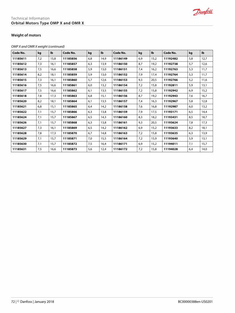
OMP X and OMR X weight (continued)
Code No. kg lb Code No. kg lb Code No. kg lb Code No. kg lb
11185611 7,2 15,8 11185856 6,8 14,9 11186149 6,9 15,2 11192482 5,8 12,7
11185612 7,3 16,1 11185857 6,3 13,9 11186150 8,7 19,2 11192738 5,7 12,6
11185613 7,5 16,6 11185858 5,9 13,0 11186151 7,4 16,2 11192763 5,3 11,7
11185614 8,2 18,1 11185859 5,9 13,0 11186152 7,9 17,4 11192764 5,3 11,7
11185615 7,3 16,1 11185860 5,7 12,6 11186153 9,3 20,5 11192766 5,2 11,6
11185616 7,5 16,6 11185861 6,0 13,2 11186154 7,2 15,8 11192811 5,9 13,1
11185617 7,5 16,6 11185862 6,1 13,5 11186155 7,2 15,8 11192942 6,9 15,2
11185618 7,8 17,3 11185863 6,8 15,1 11186156 8,7 19,2 11192943 7,6 16,7
11185620 8,2 18,1 11185864 6,1 13,5 11186157 7,4 16,3 11192967 5,8 12,8
11185621 6,8 15,1 11185865 6,4 14,2 11186158 7,6 16,8 11192987 6,0 13,2
11185622 7,1 15,7 11185866 6,3 13,8 11186159 7,9 17,5 11193171 6,5 14,4
11185624 7,1 15,7 11185867 6,5 14,3 11186160 8,3 18,2 11193431 8,5 18,7
11185626 7,1 15,7 11185868 6,3 13,8 11186161 9,3 20,5 11193624 7,8 17,3
11185627 7,3 16,1 11185869 6,5 14,2 11186162 6,9 15,2 11193633 8,2 18,1
11185628 7,8 17,3 11185870 6,7 14,8 11186163 7,2 15,8 11193635 6,3 13,9
11185629 7,1 15,7 11185871 7,0 15,5 11186164 7,2 15,9 11193640 5,9 13,1
11185630 7,1 15,7 11185872 7,5 16,4 11186171 6,9 15,2 11194011 7,1 15,7
11185631 7,5 16,6 11185873 5,6 12,4 11186172 7,2 15,8 11194028 6,4 14,0
Technical InformationOrbital Motors Type OMP X and OMR X
Weight of motors
72 | © Danfoss | January 2018 BC00000388en-US0201

Technical InformationOrbital Motors Type OMP X and OMR X
© Danfoss | January 2018 BC00000388en-US0201 | 73
Technical InformationOrbital Motors Type OMP X and OMR X
74 | © Danfoss | January 2018 BC00000388en-US0201

Technical InformationOrbital Motors Type OMP X and OMR X
© Danfoss | January 2018 BC00000388en-US0201 | 75

Danfoss Power Solutions is a global manufacturer and supplier of high-quality hydraulic andelectronic components. We specialize in providing state-of-the-art technology and solutionsthat excel in the harsh operating conditions of the mobile o�-highway market. Building onour extensive applications expertise, we work closely with our customers to ensureexceptional performance for a broad range of o�-highway vehicles.
We help OEMs around the world speed up system development, reduce costs and bringvehicles to market faster.
Danfoss – Your Strongest Partner in Mobile Hydraulics.
Go to www.powersolutions.danfoss.com for further product information.
Wherever o�-highway vehicles are at work, so is Danfoss. We o�er expert worldwide supportfor our customers, ensuring the best possible solutions for outstanding performance. Andwith an extensive network of Global Service Partners, we also provide comprehensive globalservice for all of our components.
Please contact the Danfoss Power Solution representative nearest you.
Local address:
Danfoss Power Solutions GmbH & Co. OHGKrokamp 35D-24539 Neumünster, GermanyPhone: +49 4321 871 0
Danfoss Power Solutions ApSNordborgvej 81DK-6430 Nordborg, DenmarkPhone: +45 7488 2222
Danfoss Power Solutions (US) Company2800 East 13th StreetAmes, IA 50010, USAPhone: +1 515 239 6000
Danfoss Power Solutions Trading(Shanghai) Co., Ltd.Building #22, No. 1000 Jin Hai RdJin Qiao, Pudong New DistrictShanghai, China 201206Phone: +86 21 3418 5200
Danfoss can accept no responsibility for possible errors in catalogues, brochures and other printed material. Danfoss reserves the right to alter its products without notice. This also applies to productsalready on order provided that such alterations can be made without changes being necessary in speci�cations already agreed.All trademarks in this material are property of the respective companies. Danfoss and the Danfoss logotype are trademarks of Danfoss A/S. All rights reserved.
© Danfoss | January 2018 BC00000388en-US0201
Products we o�er:
• Bent Axis Motors
• Closed Circuit Axial PistonPumps and Motors
• Displays
• Electrohydraulic PowerSteering
• Electrohydraulics
• Hydraulic Power Steering
• Integrated Systems
• Joysticks and ControlHandles
• Microcontrollers andSoftware
• Open Circuit Axial PistonPumps
• Orbital Motors
• PLUS+1® GUIDE
• Proportional Valves
• Sensors
• Steering
• Transit Mixer Drives
Comatrolwww.comatrol.com
Turolla www.turollaocg.com
Hydro-Gearwww.hydro-gear.com
Daikin-Sauer-Danfosswww.daikin-sauer-danfoss.com
BIBUS SK, s.r.oTrnavská 31, SK-94 901 Nitra Tel.: 037/ 7777 911Fax.: 037/ 7777 999
Email: [email protected]://www.bibus.sk
Top Related