


Languages
Pages
Legal

Optical Fiber Networks: Industry Trends Application InfluencesTrends, Application Influences and New Options for Networks
Herbert V Congdon II, PE
Manager, Standards & TechnologyT El t i AMP NETCONNECT S l tiTyco Electronics – AMP NETCONNECT Solutions
PreviewPreview• Deciding between OM1, OM2, OM3 and OM4
fibfiber• Options for the new 40G/100G applications
Deciding between single mode and multimode• Deciding between single-mode and multimode fiber
• Network Architecture ComparisonNetwork Architecture Comparison– Traditional Hierarchal Star– Centralized– Telecommunications Enclosures– PON
StandardsStandards• Historyy
– TIA-568-A Horizontal (100m), Intrabuilding (500m),
Interbuilding (1500m, or 2000m minus Intrabuilding)
TIA 568 B– TIA-568-B 500m became 300m Gigabit Ethernet Support Gigabit Ethernet Support
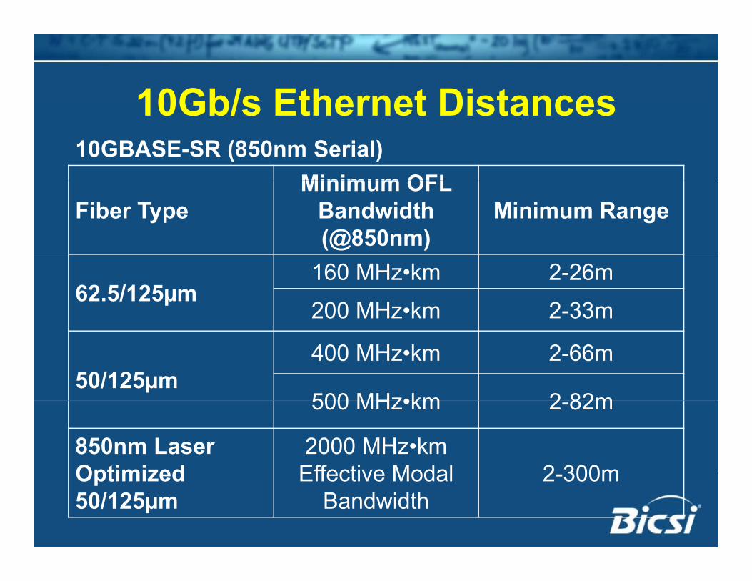
10Gb/s Ethernet Distances10Gb/s Ethernet Distances
Minimum OFL10GBASE-SR (850nm Serial)
Fiber TypeMinimum OFL
Bandwidth (@850nm)
Minimum Range
62.5/125µm160 MHz•km 2-26m
200 MHz•km 2-33m
50/125µm400 MHz•km 2-66m
500 MHz•km 2 82m500 MHz•km 2-82m
850nm Laser Optimized
2000 MHz•km Effective Modal 2 300mOptimized
50/125µmEffective Modal
Bandwidth2-300m
What about 62 5/125µm?What about 62.5/125µm?• Alive and well in legacy installationsg y• Proposals to remove it from standards
– Still a recognized mediumStill a recognized medium
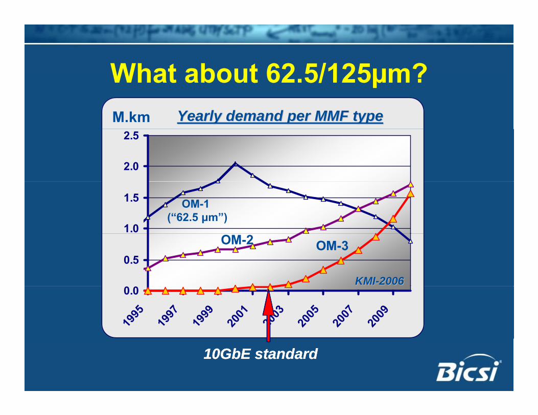
What about 62 5/125µm?What about 62.5/125µm?M.km Yearly demand per MMF typeYearly demand per MMF typeM.km Yearly demand per MMF typeYearly demand per MMF type
2.0
2.5
2.0
2.5
1.0
1.5 OM-1 (“62.5 μm”)
1.0
1.5 OM-1 (“62.5 μm”)
0.5OM-3OM-2
KMIKMI--20062006
0.5OM-3OM-2
KMIKMI--200620060.0
1995
1997
1999
2001
2003
2005
2007
2009
0.0
1995
1997
1999
2001
2003
2005
2007
2009
10GbE standard10GbE standard
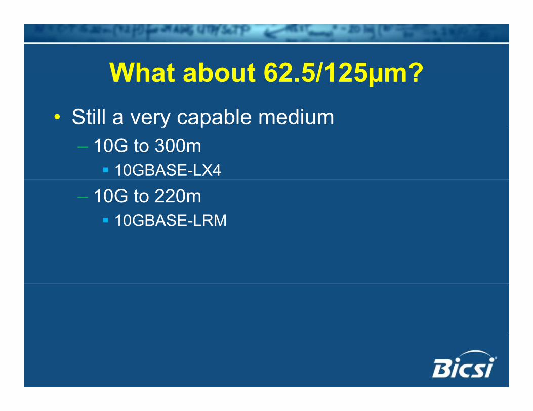
What about 62 5/125µm?What about 62.5/125µm?• Still a very capable mediumy p
– 10G to 300m 10GBASE-LX4
– 10G to 220m 10GBASE-LRM
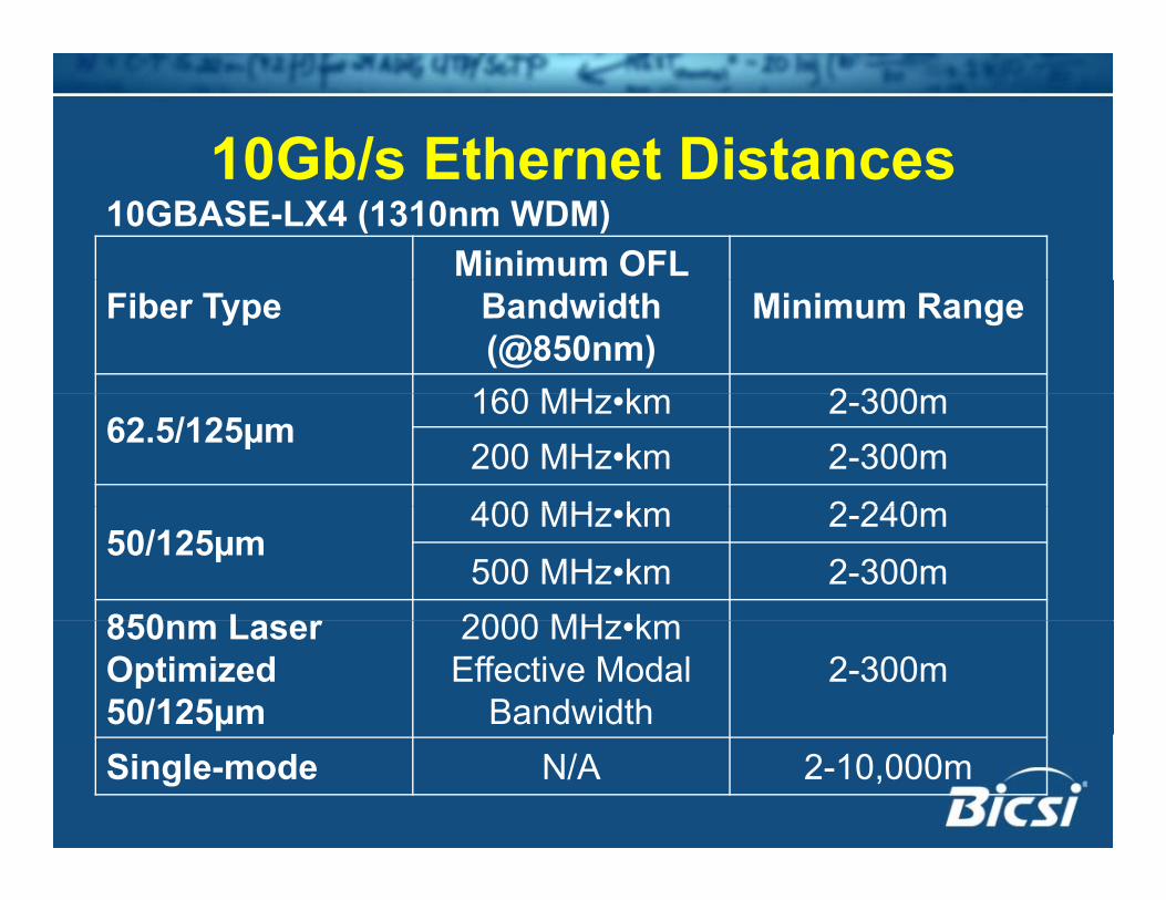
10Gb/s Ethernet Distances10Gb/s Ethernet DistancesMinimum OFL
10GBASE-LX4 (1310nm WDM)
Fiber Type Bandwidth (@850nm)
Minimum Range
160 MH k 2 30062.5/125µm
160 MHz•km 2-300m200 MHz•km 2-300m400 MH k 2 240
50/125µm400 MHz•km 2-240m500 MHz•km 2-300m
850nm Laser 2000 MH km850nm Laser Optimized 50/125µm
2000 MHz•km Effective Modal
Bandwidth2-300m
Single-mode N/A 2-10,000m
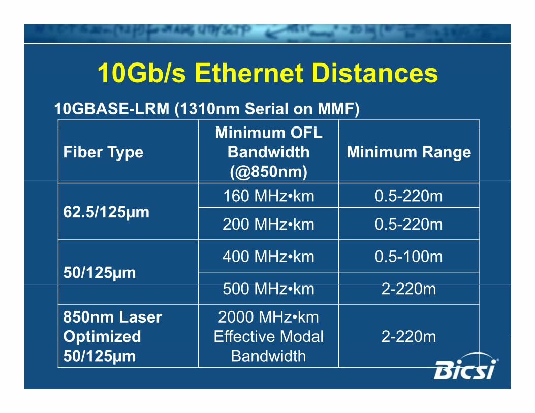
10Gb/s Ethernet Distances10Gb/s Ethernet Distances10GBASE-LRM (1310nm Serial on MMF)
Mi i OFLFiber Type
Minimum OFL Bandwidth (@850nm)
Minimum Range
62.5/125µm160 MHz•km 0.5-220m
200 MHz•km 0.5-220m
50/125µm400 MHz•km 0.5-100m
500 MH k 2 220500 MHz•km 2-220m
850nm Laser Optimized
2000 MHz•km Effective Modal 2 220mOptimized
50/125µmEffective Modal
Bandwidth2-220m
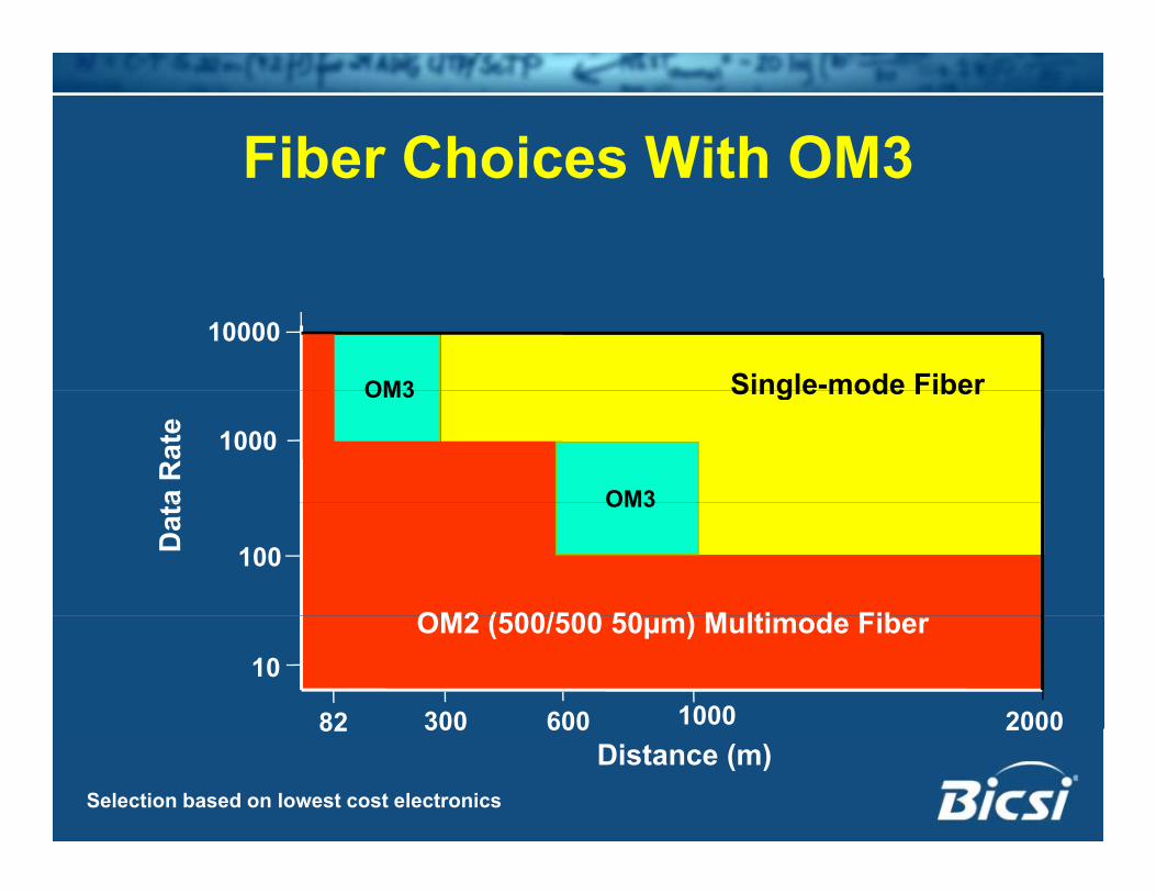
Fiber Choices With OM3Fiber Choices With OM3
10000
OM3 Single-mode FiberOM3
1000
Single mode Fiber
a R
ate
OM3
OM2 (500/500 50 ) M lti d Fib
100Dat
a OM3
300 600 2000
OM2 (500/500 50µm) Multimode Fiber10
100082Distance (m)
300 600 2000
Selection based on lowest cost electronics
82
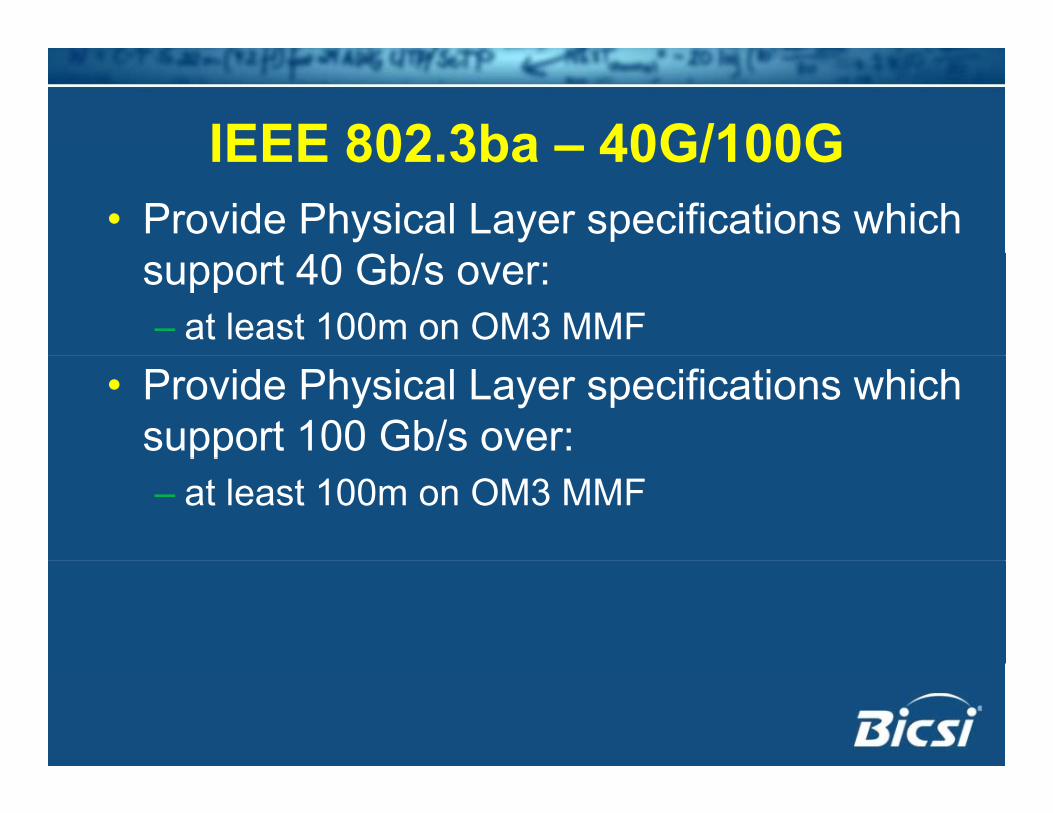
IEEE 802 3ba – 40G/100GIEEE 802.3ba – 40G/100G• Provide Physical Layer specifications which
support 40 Gb/s over:– at least 100m on OM3 MMF
• Provide Physical Layer specifications which support 100 Gb/s over:pp– at least 100m on OM3 MMF
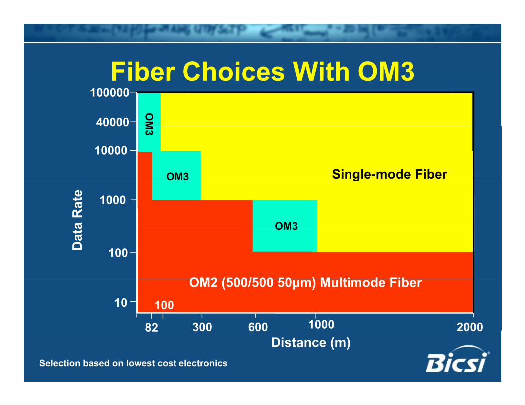
Fiber Choices With OM3Fiber Choices With OM3100000
40000
OM
10000
OM3 Single-mode Fiber
40000 M3
OM3
1000
Single mode Fiber
a R
ate
OM3
OM2 (500/500 50 ) M lti d Fib
100Dat
a OM3
300 600 2000
OM2 (500/500 50µm) Multimode Fiber10
100082
100
Distance (m)300 600 2000
Selection based on lowest cost electronics
82
40G/100G Questions40G/100G Questions• Why 100m not 300m?y
– at least 100m on OM3 MMF
• How can you get the same distance on the same fiber at 2 5x the data rate?same fiber at 2.5x the data rate?– 40G and 100G
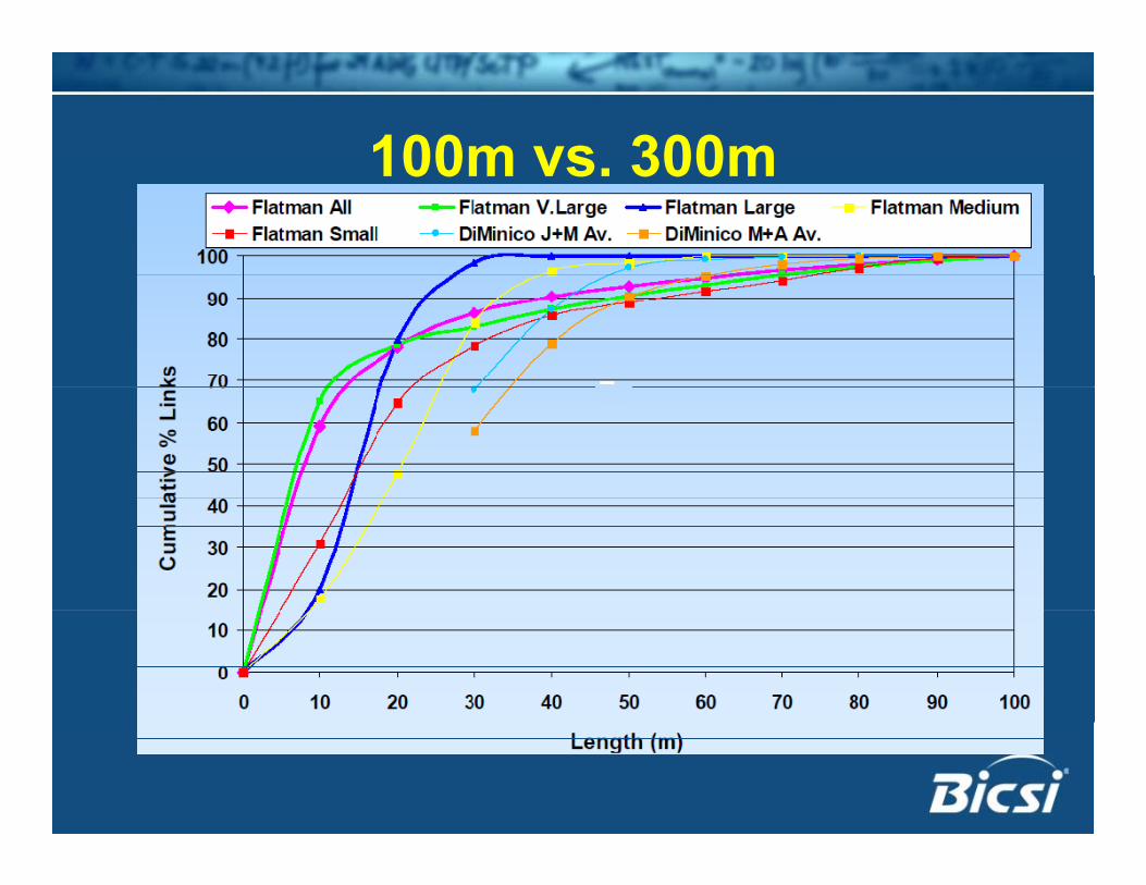
100m vs 300m100m vs. 300m• The IEEE Cost Objectivej
– 10x the data rate at 3x the cost
• How do you get four 10G channels at 1.2x the cost of one 10G channel?the cost of one 10G channel?
• How do you get ten 10G channels at 3x th t f 10G h l?the cost of one 10G channel?
100m vs 300m100m vs. 300m• Serial VCSELS
– Technology tops out at ~20-25G
• Wave Division Multiplexing10λ separation difficult in 850nm window– 10λ separation difficult in 850nm window
– No cost savings on the electronics
100m vs 300m100m vs. 300m• Parallel
– Requires more fibers– Requires cost reduction on 10Gq Relaxed transceiver specifications
• Better FiberOM4 fiber– OM4 fiber
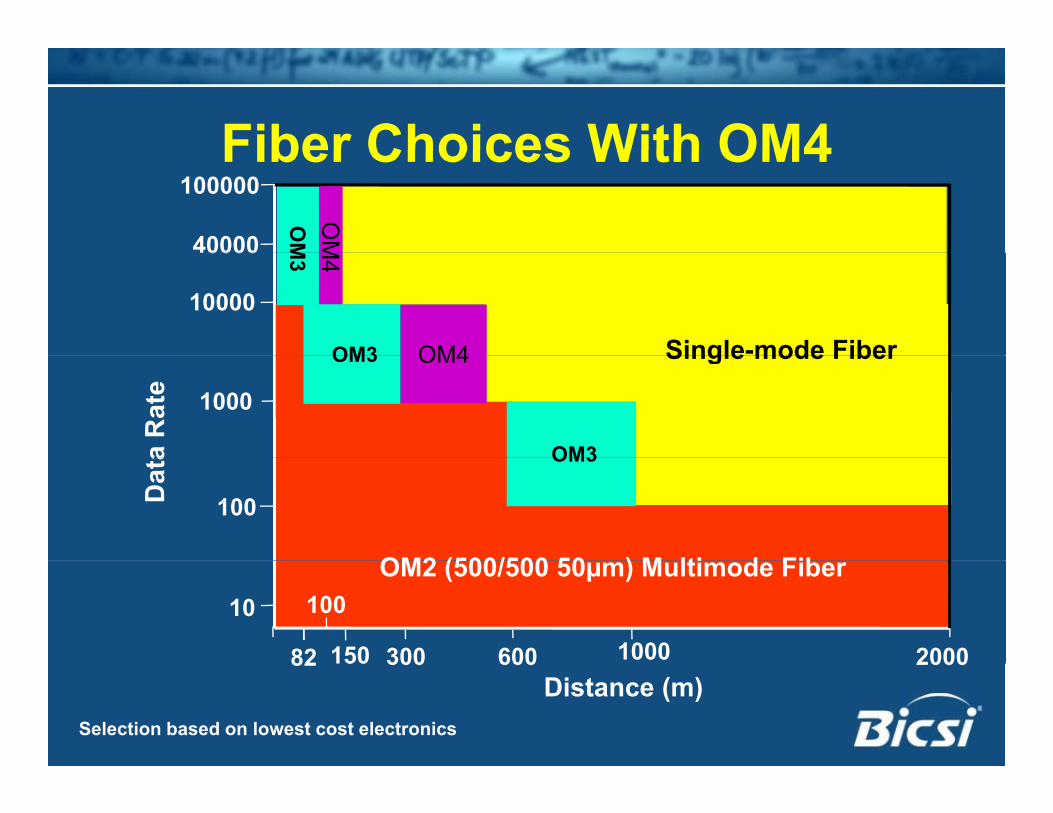
Fiber Choices With OM4Fiber Choices With OM4100000
40000
OM
OM
10000
Single-mode FiberOM4
40000 M3
M4
OM3
1000
Single mode FiberOM4
a R
ate
OM3
OM3
OM2 (500/500 50 ) M lti d Fib
100Dat
a OM3
300 600 2000
OM2 (500/500 50µm) Multimode Fiber10
100082 150
100
Distance (m)300 600 2000
Selection based on lowest cost electronics
82 150
100m vs 300m100m vs. 300m
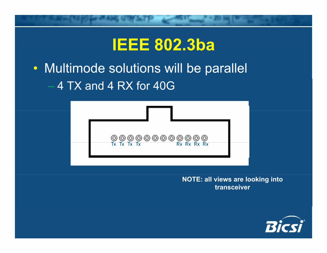
IEEE 802 3baIEEE 802.3ba• Multimode solutions will be parallel
– 4 TX and 4 RX for 40G
NOTE: all views are looking into transceiver
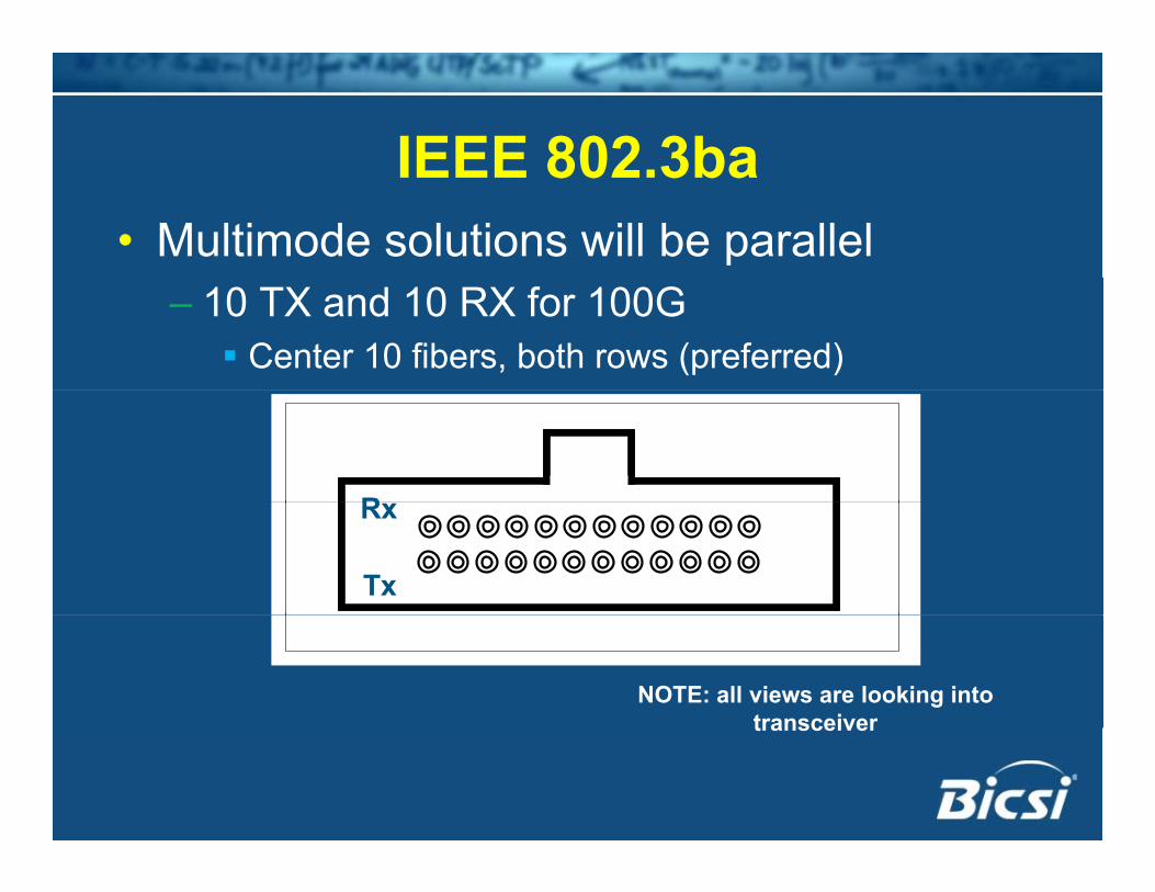
IEEE 802 3baIEEE 802.3ba• Multimode solutions will be parallel
– 10 TX and 10 RX for 100G Center 10 fibers, both rows (preferred)
RR
Tx
Rx
Tx
Rx
NOTE: all views are looking into transceivertransceiver
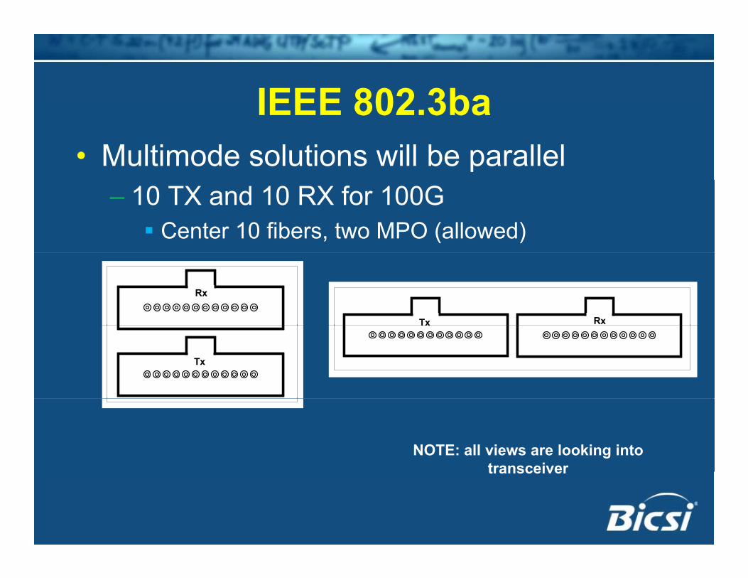
IEEE 802 3baIEEE 802.3ba• Multimode solutions will be parallel
– 10 TX and 10 RX for 100G Center 10 fibers, two MPO (allowed)
RxRx
Tx RxTx Rx
TxTx
NOTE: all views are looking into transceivertransceiver
IEEE 802 3baIEEE 802.3ba• No lane assignments (1-4 or 1-10)
– Protocol will self-detect– Reduces importance of polarity for these
applications
• Skew budget very generous– Not likely to be a concern unless building with y g
duplex links with a length differential more than 15 meters
Standards & PolarityStandards & Polarity• Component Polarity (Illustrated)p y ( )
– ANSI/TIA 568-C.3
• System Polarity (Illustrated)ANSI/TIA 568 C 0– ANSI/TIA 568-C.0
Standards & PolarityStandards & Polarity• Component Polarity – Array Patch Cords
– Type A: 1-to-1…12-to-12– Type B: 1-to-12…12-to-1– Type C: 1-to-2; 2-to-1 11-to-12– Type C: 1-to-2; 2-to-1…11-to-12
• Component Polarity – Adapters– Type A: Key Up to Key Downyp y p y– Type B: Key Up to Key Up
• Component Polarity – Duplex Patch Cords– A-to-B– A-to-A
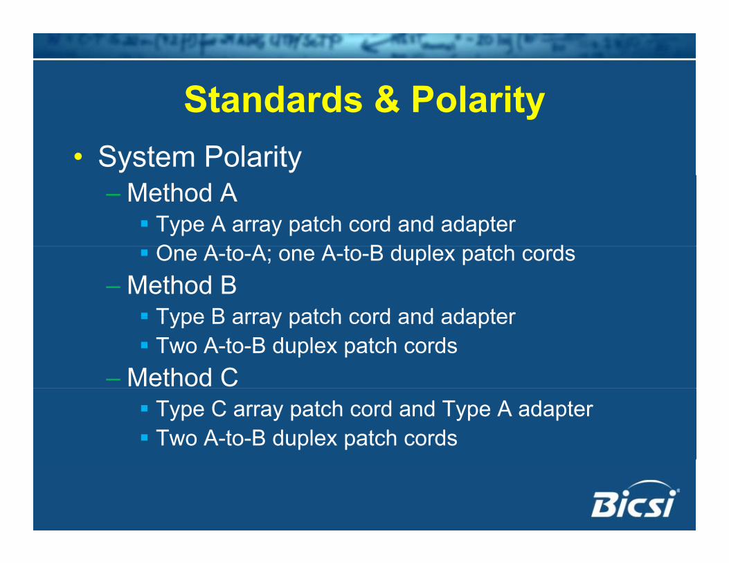
Standards & PolarityStandards & Polarity• System Polarity
– Method A Type A array patch cord and adapter
O A t A A t B d l t h d One A-to-A; one A-to-B duplex patch cords– Method B Type B array patch cord and adapter Type B array patch cord and adapter Two A-to-B duplex patch cords
– Method C Type C array patch cord and Type A adapter Two A-to-B duplex patch cords
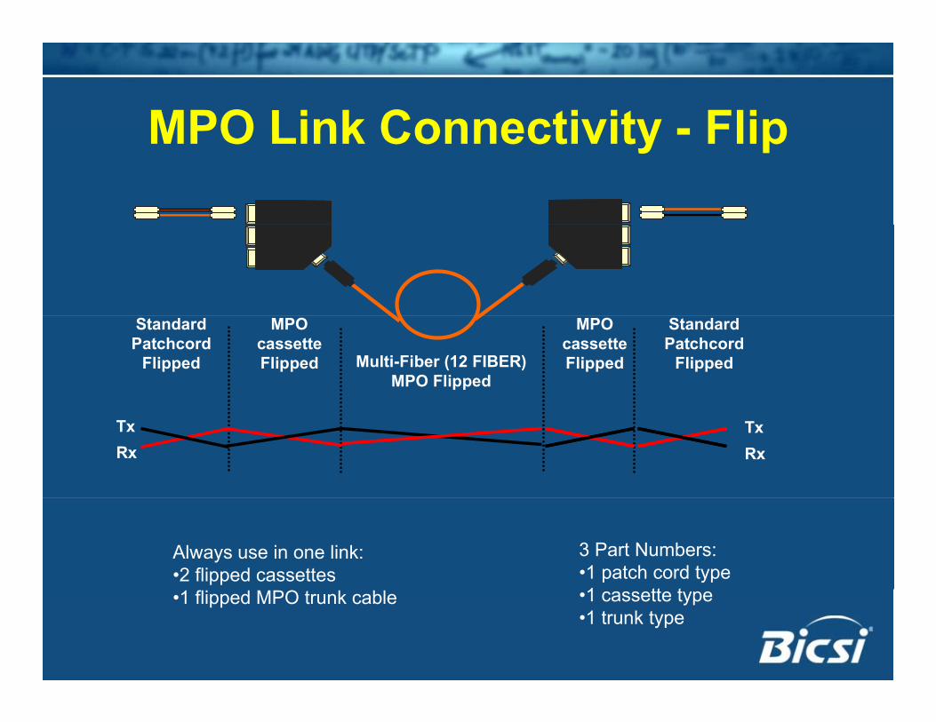
MPO Link Connectivity - FlipMPO Link Connectivity - Flip
MPO cassette Flipped
MPO cassette Flipped Multi-Fiber (12 FIBER)
MPO Flipped
Standard Patchcord
Flipped
Standard Patchcord
Flipped
TxRx
TxRx
Always use in one link: •2 flipped cassettes
3 Part Numbers:•1 patch cord type1 tt t•1 flipped MPO trunk cable •1 cassette type
•1 trunk type
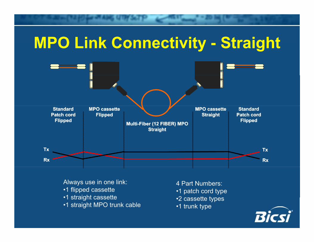
MPO Link Connectivity - StraightMPO Link Connectivity - Straight
MPO cassette Straight
MPO cassette Flipped
Multi-Fiber (12 FIBER) MPO Straight
Standard Patch cord
Flipped
Standard Patch cord
Flipped
MPO cassette Straight
MPO cassette Flipped
Multi-Fiber (12 FIBER) MPO Straight
Standard Patch cord
Flipped
Standard Patch cord
Flipped
Tx
Rx
Tx
Rx
Tx
Rx
Tx
Rx
Always use in one link:•1 flipped cassette •1 straight cassette
4 Part Numbers:•1 patch cord type2 tt t•1 straight cassette
•1 straight MPO trunk cable•2 cassette types•1 trunk type
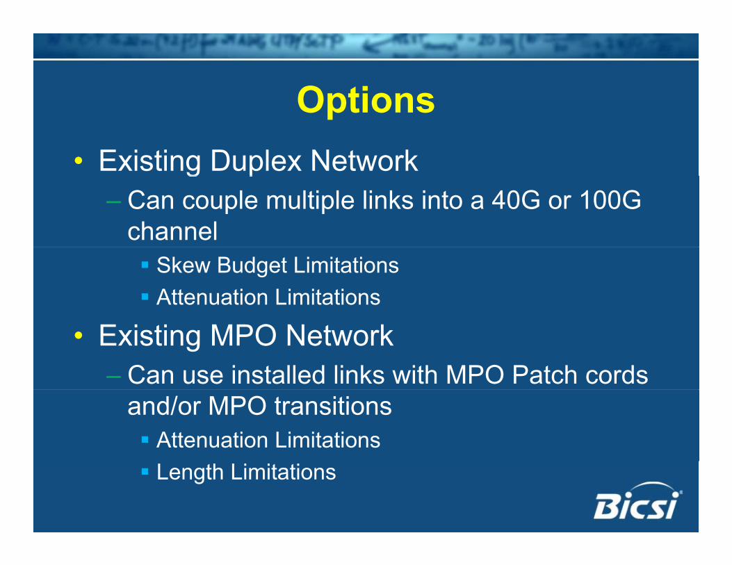
OptionsOptions• Existing Duplex Networkg p
– Can couple multiple links into a 40G or 100G channel Skew Budget Limitations Attenuation Limitations
• Existing MPO Network– Can use installed links with MPO Patch cords
and/or MPO transitions Attenuation Limitations Length Limitations
Why not just jump to Single-mode?
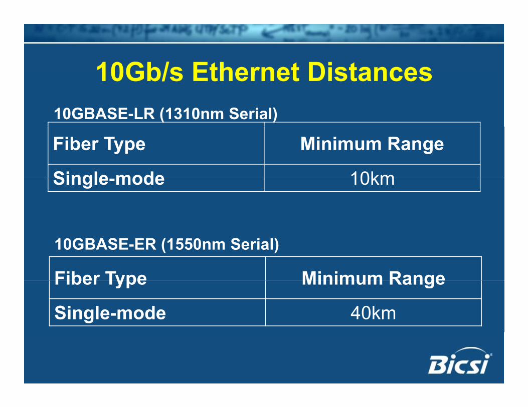
10Gb/s Ethernet Distances10Gb/s Ethernet Distances10GBASE-LR (1310nm Serial)
Fiber Type Minimum Range
Single mode 10kmSingle-mode 10km
10GBASE-ER (1550nm Serial)
Fiber Type Minimum RangeFiber Type Minimum Range
Single-mode 40km
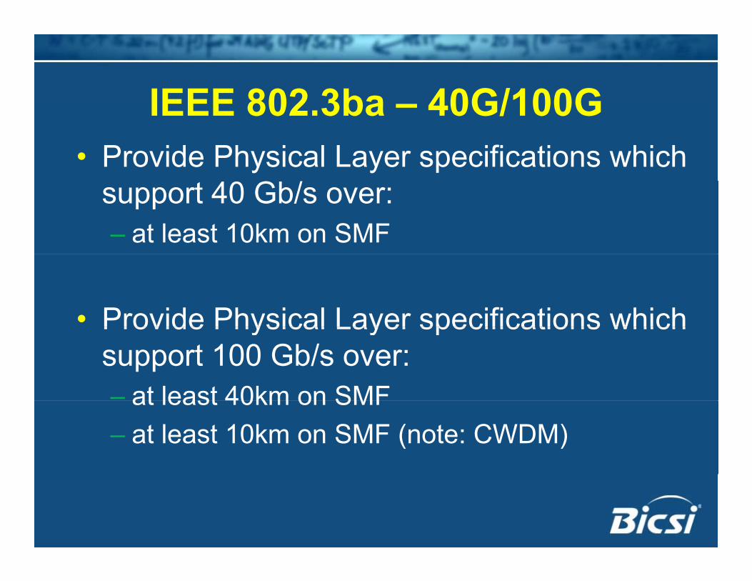
IEEE 802 3ba – 40G/100GIEEE 802.3ba – 40G/100G• Provide Physical Layer specifications which
support 40 Gb/s over:– at least 10km on SMF
• Provide Physical Layer specifications whichProvide Physical Layer specifications which support 100 Gb/s over:– at least 40km on SMFat least 40km on SMF– at least 10km on SMF (note: CWDM)
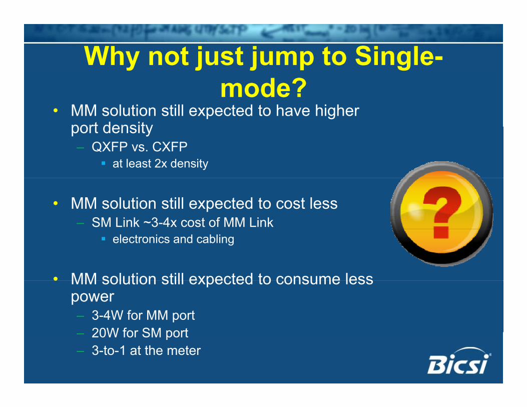
Why not just jump to Single-mode?
• MM solution still expected to have higher port densityport density– QXFP vs. CXFP
at least 2x density
• MM solution still expected to cost less– SM Link ~3-4x cost of MM Link
electronics and cabling
• MM solution still expected to consume less• MM solution still expected to consume less power– 3-4W for MM port
20W for SM port– 20W for SM port– 3-to-1 at the meter
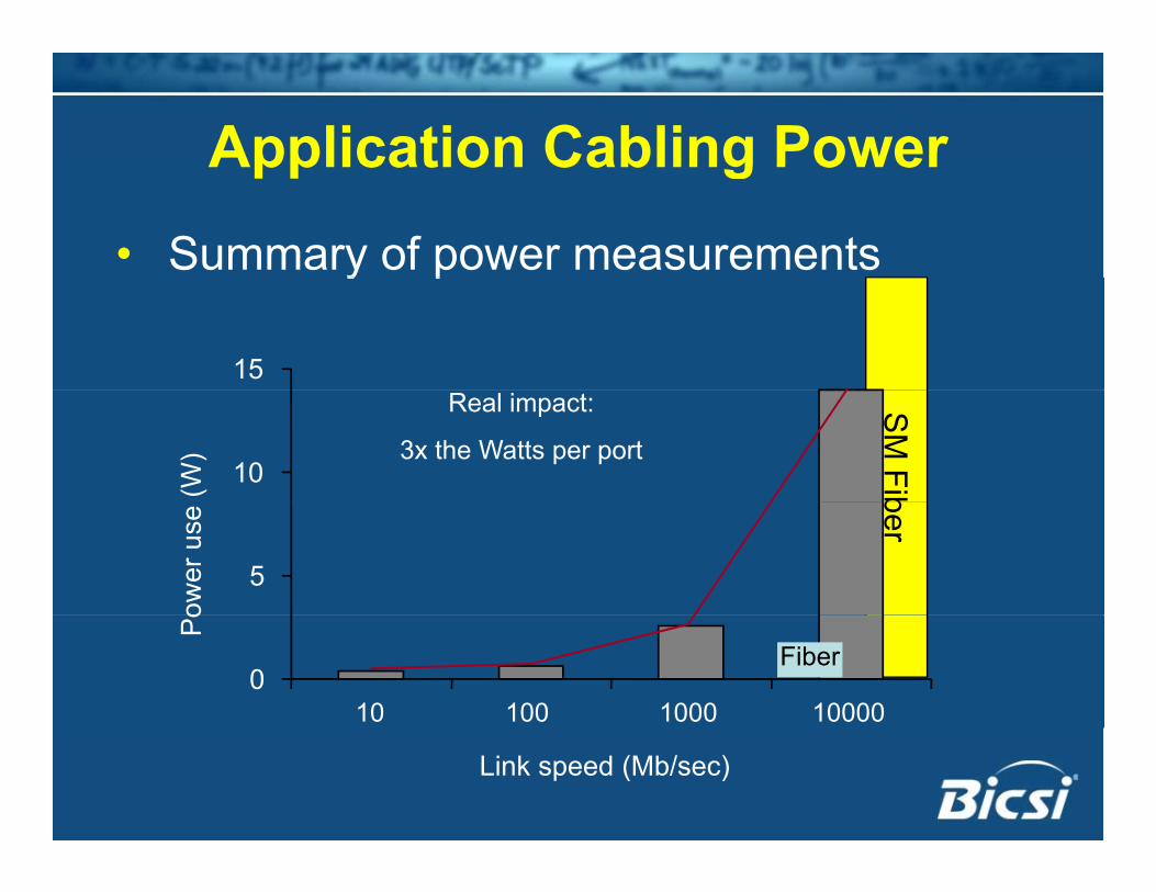
Application Cabling Power
• Summary of power measurements
Application Cabling Power
y p
15
SM
Fib10(W)
Real impact:
3x the Watts per port
ber
5
ower
use
0
Po
10 100 1000 10000
Fiber
Link speed (Mb/sec)
Structured Cabling System Architectures Evolve
• 1991– TIA 568 standard ratified with Hierarchical
Star Architecture Optimized for copper performance characteristics
& limitations100 t h i t l bli b t li it 100 meter horizontal cabling subsystem limit
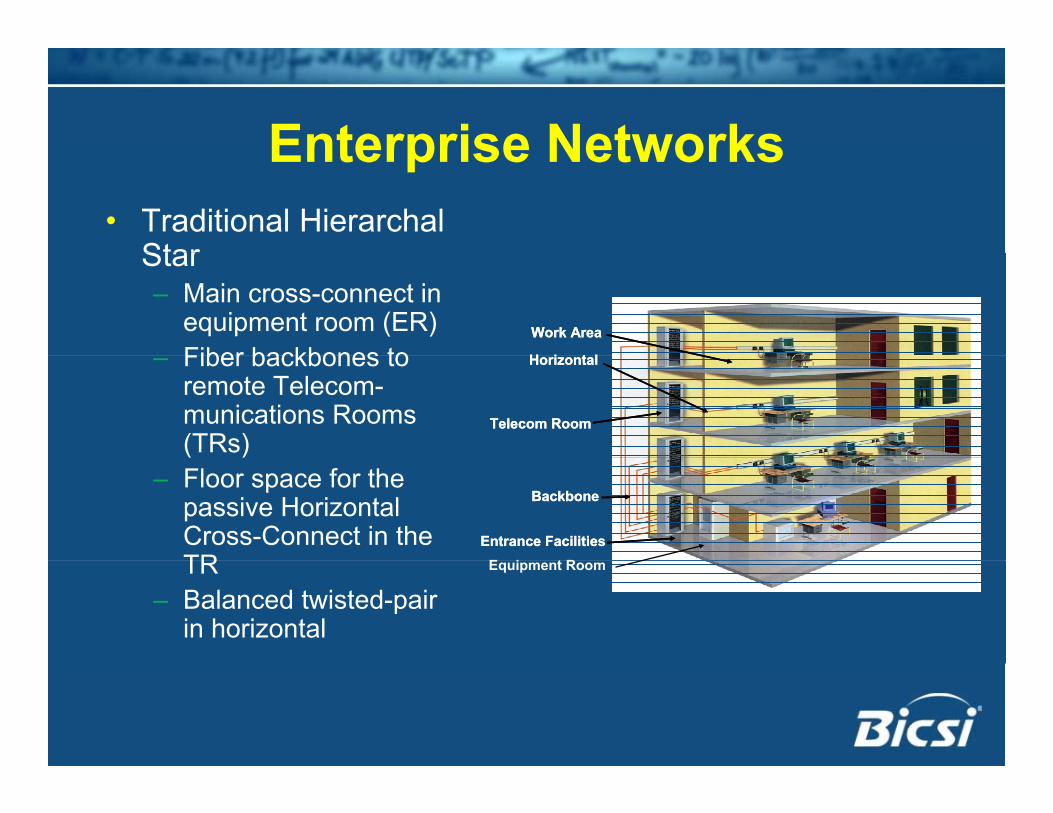
Enterprise NetworksEnterprise Networks• Traditional Hierarchal
StarStar– Main cross-connect in
equipment room (ER)Fiber backbones to
Work AreaWork Area
H i t lH i t l– Fiber backbones to remote Telecom-munications Rooms (TRs)
HorizontalHorizontal
Telecom RoomTelecom Room
– Floor space for the passive Horizontal Cross-Connect in the TR
BackboneBackbone
Entrance FacilitiesEntrance FacilitiesE i t RTR
– Balanced twisted-pair in horizontal
Equipment Room
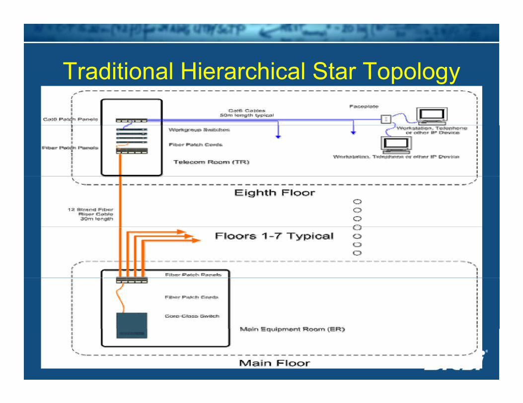
Traditional Hierarchical Star TopologyTraditional Hierarchical Star Topology
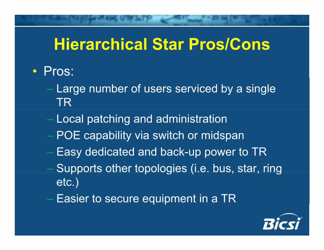
Hierarchical Star Pros/ConsHierarchical Star Pros/Cons• Pros:
– Large number of users serviced by a single TR
– Local patching and administration– POE capability via switch or midspan p y p– Easy dedicated and back-up power to TR– Supports other topologies (i.e. bus, star, ring pp p g ( , , g
etc.) – Easier to secure equipment in a TRq p
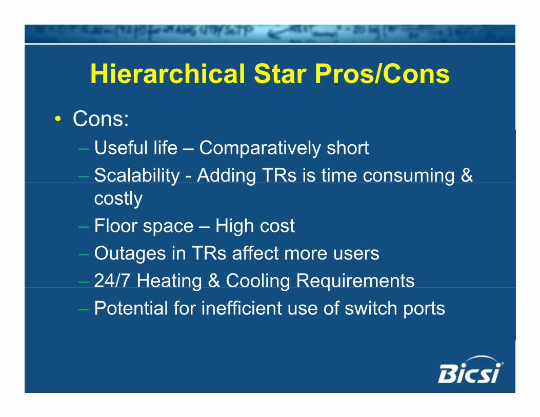
Hierarchical Star Pros/ConsHierarchical Star Pros/Cons• Cons:
– Useful life – Comparatively short– Scalability - Adding TRs is time consuming & y g g
costly– Floor space – High costp g– Outages in TRs affect more users– 24/7 Heating & Cooling Requirementsg g q– Potential for inefficient use of switch ports
Structured Cabling System Architectures Evolve
• 1995– TSB-72 “Centralized Fiber Optic Guidelines”
• 20012001– TIA 568-B.1 supports centralized cabling
Enterprise NetworksEnterprise Networks• Centralized Cablingg
– Main Cross-Connect in Equipment Room– Horizontal cables from ER end at work area– For fiber: TR only functions as passive optical
interconnect/patchp
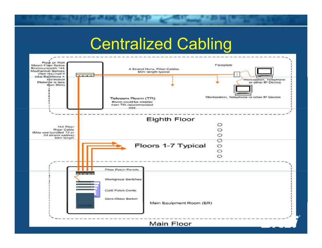
Centralized CablingCentralized Cabling
Centralized Fiber CablingCentralized Fiber Cabling• Pull-through from the ER to the WAg
– 90 meters or less• Pass through a TR with interconnect orPass through a TR with interconnect or
splice– Over 90m (fiber)– Over 90m (fiber)
• All the electronics are within the ERT i ll 2 4 fib bl h t• Typically, 2-4 fiber cables are home-run to WA
Centralized Pros/ConsCentralized Pros/Cons• Pros:
– Security - no switch gear outside of ER– Longer horizontal potential (>100m)g p ( )– Minimal number of TRs required– Most efficient use of switch portsMost efficient use of switch ports– Centralized power and back-up
Centralized Fiber Pros/ConsCentralized Fiber Pros/Cons• Cons:
– Cost may be comparatively high (esp. FTTD) Media converters vs. NICs
– Scale - Infrastructure changes more difficult– Familiarity & Acceptancey p– Migrate to a converged network– Cable congestion in ERCable congestion in ER– POE not supported (fiber)
Structured Cabling System Architectures Evolve
• 2005: TIA 569-B & 568-B.1-5 supports pp“Telecom Enclosure” (TE)
Enterprise NetworksEnterprise Networks• Fiber To The Enclosure (FTTE)( )
– Main cross-connect in ER– Fiber backbone through TR to remote TEsg– Copper to WA
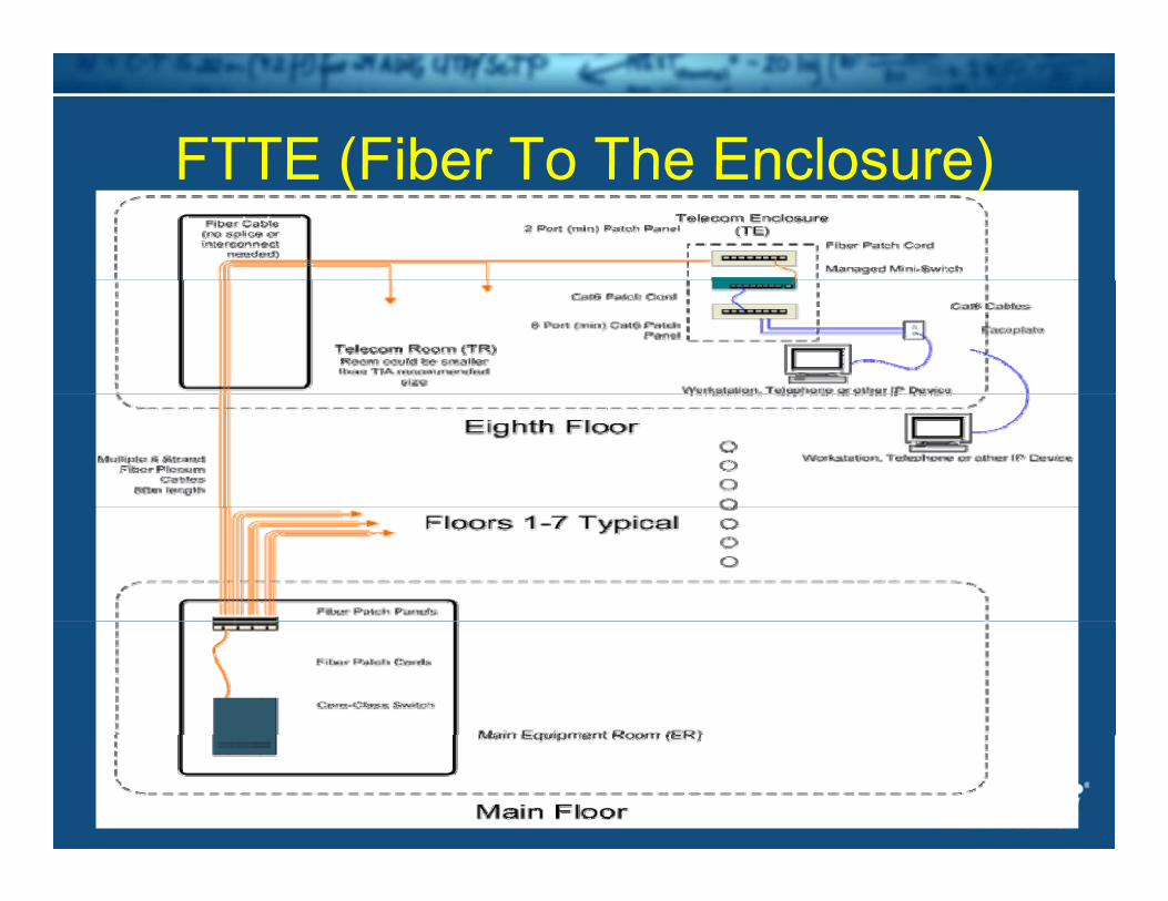
FTTE (Fiber To The Enclosure)FTTE (Fiber To The Enclosure)
FTTEFTTE• Allowed up to 300 meters to the TEp• Horizontal cross-connect in TE, not TR• Still need a TR• Still need a TR
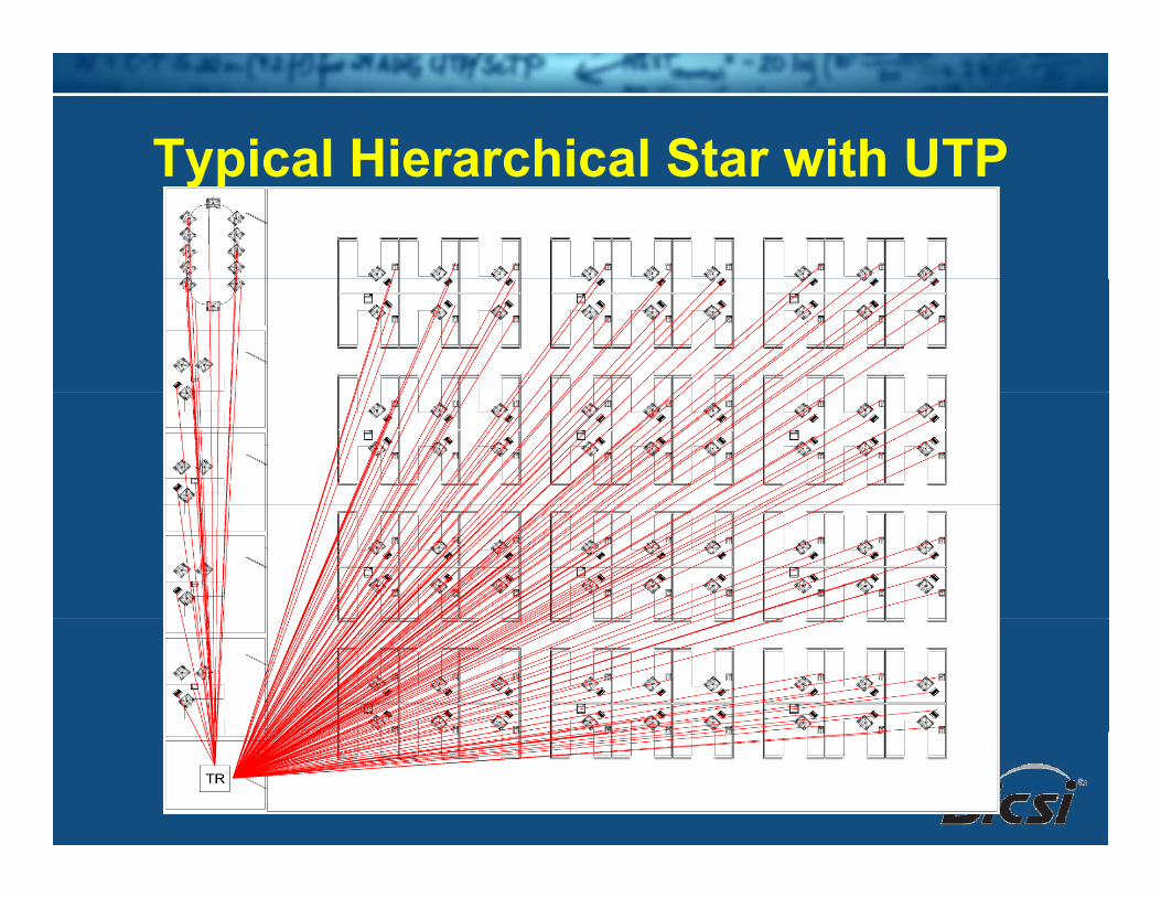
Typical Hierarchical Star with UTPTypical Hierarchical Star with UTP
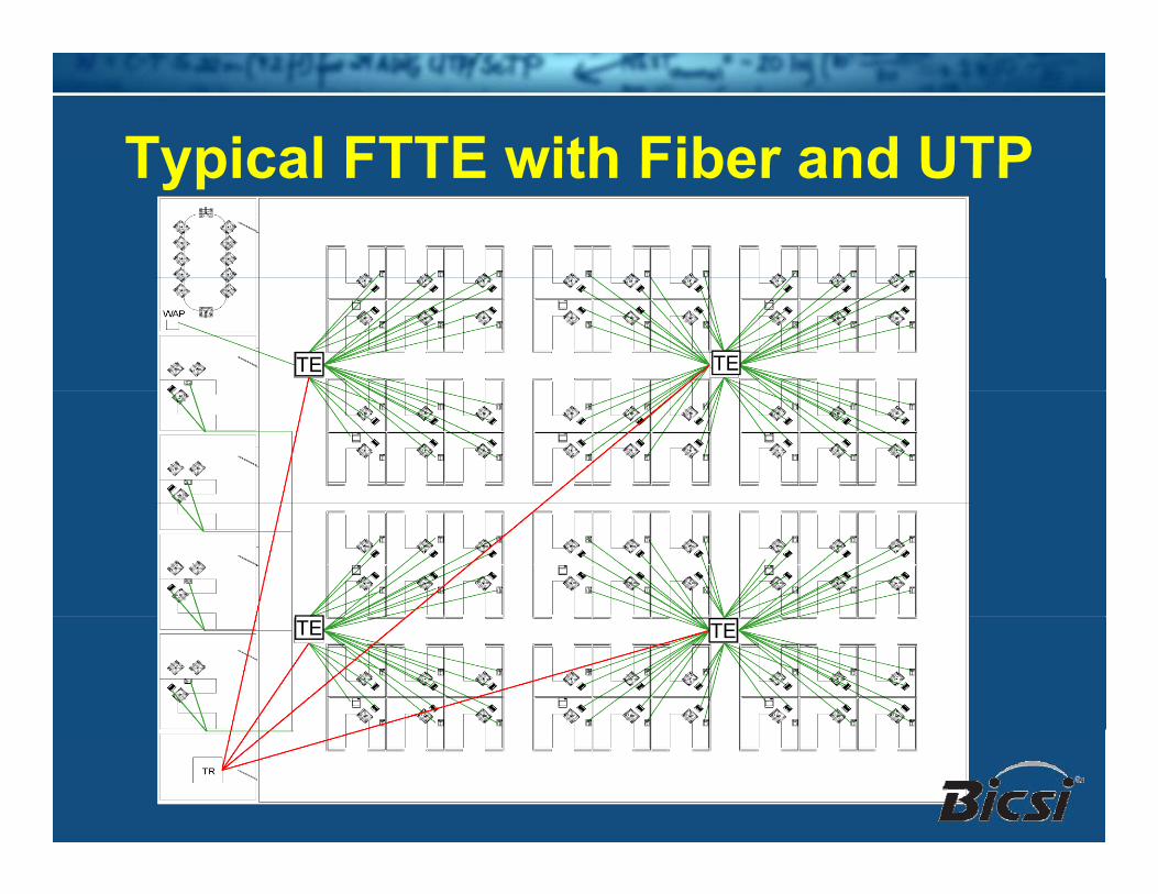
Typical FTTE with Fiber and UTPTypical FTTE with Fiber and UTP
TE TE
TE TE
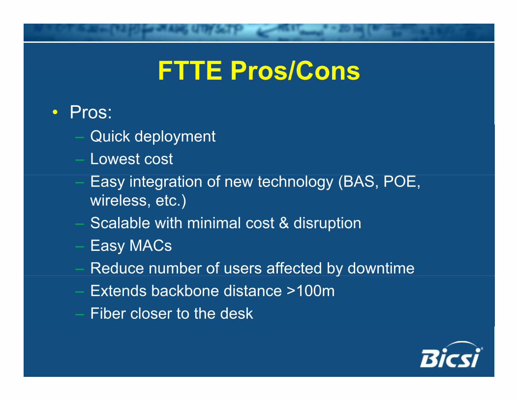
FTTE Pros/ConsFTTE Pros/Cons• Pros:
– Quick deployment – Lowest cost– Easy integration of new technology (BAS, POE,
wireless, etc.)– Scalable with minimal cost & disruptionScalable with minimal cost & disruption– Easy MACs– Reduce number of users affected by downtimey– Extends backbone distance >100m– Fiber closer to the desk
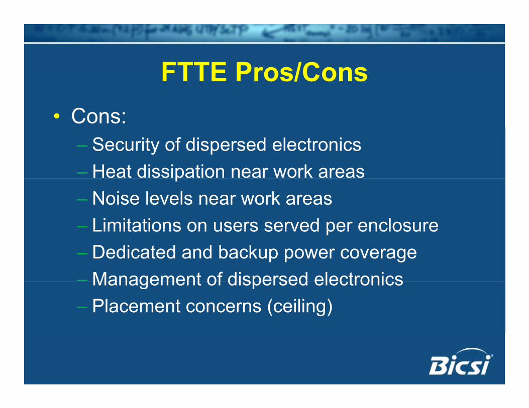
FTTE Pros/ConsFTTE Pros/Cons• Cons:
– Security of dispersed electronics– Heat dissipation near work areasp– Noise levels near work areas– Limitations on users served per enclosureLimitations on users served per enclosure– Dedicated and backup power coverage– Management of dispersed electronicsManagement of dispersed electronics– Placement concerns (ceiling)
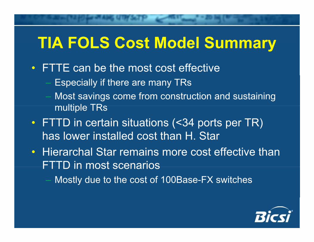
TIA FOLS Cost Model SummaryTIA FOLS Cost Model Summary• FTTE can be the most cost effective
– Especially if there are many TRs– Most savings come from construction and sustaining
multiple TRsmultiple TRs• FTTD in certain situations (<34 ports per TR)
has lower installed cost than H Starhas lower installed cost than H. Star• Hierarchal Star remains more cost effective than
FTTD in most scenariosFTTD in most scenarios– Mostly due to the cost of 100Base-FX switches
New ProposalsNew Proposals• Passive Optical Network (PON)p ( )
– Fiber to the Home• Passive Optical LAN (POL)Passive Optical LAN (POL)
– All simplex, single-mode fiber cablingPoint-to-multipoint– Point-to-multipoint
– Splitters instead of patch panels
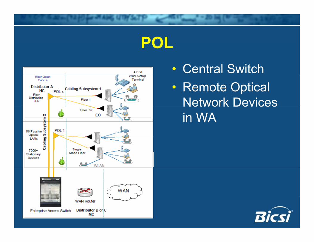
POLPOL• Central Switch• Remote Optical
Network DevicesNetwork Devices in WA
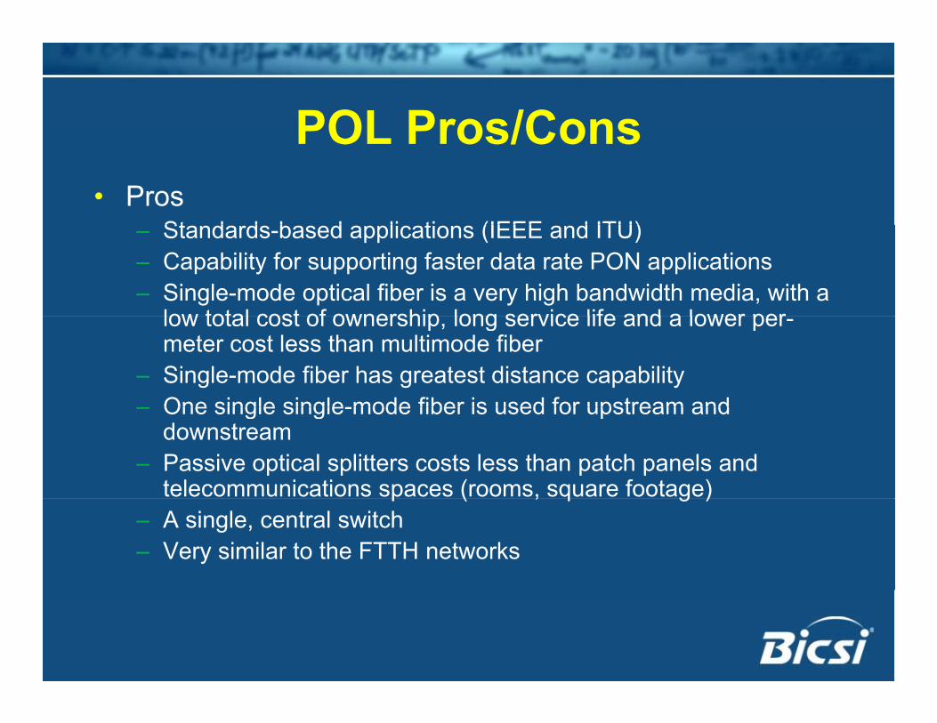
POL Pros/ConsPOL Pros/Cons• Pros
St d d b d li ti (IEEE d ITU)– Standards-based applications (IEEE and ITU)– Capability for supporting faster data rate PON applications– Single-mode optical fiber is a very high bandwidth media, with a
low total cost of ownership long service life and a lower perlow total cost of ownership, long service life and a lower per-meter cost less than multimode fiber
– Single-mode fiber has greatest distance capability– One single single-mode fiber is used for upstream and– One single single-mode fiber is used for upstream and
downstream– Passive optical splitters costs less than patch panels and
telecommunications spaces (rooms, square footage)p ( , q g )– A single, central switch– Very similar to the FTTH networks
POL Pros/ConsPOL Pros/Cons• Cons
– Shared bandwidth– Broadcast technology - security concerns– Single-mode connectivity more expensive– Single-mode connectivity more expensive– Simplex point-to-multipoint cabling infrastructure is
not TIA compliant– No projects to develop a 10G or higher PON– The single central switch is comparatively expensive– Network terminal devices need local power supply &Network terminal devices need local power supply &
backup– The Power Over Ethernet and Power Over Ethernet
Plus applications not supported by the POLPlus applications not supported by the POL
Other TopicsOther Topics• Types of Single-mode Fiberyp g• Bend-insensitive Fiber
Types of Single-mode FiberTypes of Single-mode Fiber• Standard Single-modeg
– Dispersion Unshifted Single-mode Fiber– Commonly deployed in LAN backbonesy p y
• Low Water Peak Single-modeDispersion Unshifted Single-mode Fiber– Dispersion Unshifted Single-mode Fiber
– Lower attenuation in 1383nm windowNon ero Dispersion shifted Single mode• Non-zero Dispersion-shifted Single-mode– Optimized for operation in 1550nm window
Bend Insensitive FiberBend Insensitive Fiber• Multimode and Single-modeg• Attenuation is less sensitive to tight bends
and bending stressand bending stress• Able to withstand “poor” installation
Still pass the attenuation limits– Still pass the attenuation limits• May “hide” minimum bend radius
i l tiviolations
SummarySummary
SummarySummary• Options for the 40G/100G applicationsp pp
– Duplex Single-mode Cost and density
– Parallel (MPO) Multimode OM3 or OM4 – pick based on distance
– Polarity Tx to Rx
• Is 62.5/125µm dead?– No, but not a 40G/100G media,
SummarySummary• Telecommunications Enclosures
– Supplements TRs– Not recommended, but allowed,– Can be cost-effective
• PONs and POLs• PONs and POLs– Simplex, single-mode, passive infrastructure
Not currently cabling standards compliant– Not currently cabling standards compliant
SummarySummary• No option is perfect for every environment p p y
so consider all factors and choose based on individual requirementsq
• FOLS Cost Model is a good resource for evaluating optionsevaluating options– www.fols.org for cost model and questions
Top Related