


![Operators Manual - PDF.TEXTFILES.COMpdf.textfiles.com/manuals/ARCADE/A-J/Alpine Racer (46in) [Operator's] [English].pdf · part no. 90500040 operators manual it is the responsibility](https://static.fdocuments.us/doc/165x107/5ced773c88c993350f8c6754/operators-manual-pdf-racer-46in-operators-englishpdf-part-no-90500040.jpg)


Languages
Pages
Legal


Operators Manual
IT IS THE RESPONSIBILITY OF THE OPERATOR TO MAINTAIN CUSTOMER SAFETY
AT ALL TIMES, AND IT IS IMPERATIVE THAT THE DETAILS SET OUT IN THIS
MANUAL ARE FOLLOWED PRECISELY.
Part No. 90500092

© 1996 NAMCO LIMITED all rights reserved.
No part of this publication may be reproduced by any mechanical, photographic or electronicprocess, or in the form of phonographic recording, nor may it be stored in a retrieval system,transmitted or otherwise copied for public or private use, without permission from
NAMCO EUROPE LIMITED.
While the information contained in this manual is given in good faith and was accurate atthe time of printing, NAMCO EUROPE LIMITED reserve the right to make changes andalterations without notice.
This machine has been manufactured in accordance with European Community Directives, andhas been tested and complies with the EMC Directive 89/336/EEC by the application of EN55014and EN55104 standards (see opposite), and as such bears the marking. Any changes ormodifications to this machine must be in accordance with European Community Directives. Anyunauthorised changes to this product, may contravene such Directives.
Under some conditions of extreme external interference, e.g. radio transmissions, electrostaticdischarge or mains borne transients, some degradation of performance may occur. However themachine will recover normal performance once the source of interference has ceased or beenremoved.Note:-If the game processor resets due to an interuption or reduction of the mains voltage any creditsestablished may be lost.
This game is not a machine as defined by the Machinery Directive 89/392/EEC
Published by:NAMCO EUROPE LIMITEDNamco House,Acton Park Estate,The Vale,London W3 7QE
Phone:- 0208-324-6000Fax:- 0208-324-6010

SAFETY WARNING
In order to use this machine safely, be sure to read this Operators Manual carefully beforeinstallation, adjustment or use of this machine.Whenever the owner of this machine entrusts dis-assembly, installation, adjustment or routinemaintenance to another person, the owner should ensure that that person read the appropriateprecautions and relevant sections of this manual before starting work.In order that no accidents occur when the machine is in operation, strictly follow the noteson safety as described below.
This manual along with the Installation Manual (where applicable) form an integral part of theequipment and must be available to the operating and service personnel at all times.
This machine is for indoor use only and should be used only for the purpose intended.
Namco Ltd. bears no responsibility for accidents, injury or damage resulting from unauthorizedchanges to, or improper use of this machine.
SAFETY NOTES
The following safety notes are used throughout this manual. Familiarize yourself witheach of these notes and its meaning before installing, servicing or making adjustmentto this machine.
WARNING Warning denotes a hazard that could result in injury or death.Do not proceed beyond a warning note until the indicatedconditions are fully understood and met.
CAUTION Caution denotes a hazard that could result in damage to the machine.Do not proceed beyond a warning note until the indicated conditionsare fully understood and met.

General Safety Considerations
WARNING • Only operate this machine after checking that has beeninstalled correctly and in accordance with the manual.
• Parts of this machine move during game play, so there areplaces where the distance between the stationary section andmoveable section changes. There are warning notices to keephands and feet clear of moving parts, however if the operatorfeels that a person is in any danger, he should warn thatperson accordingly.
• The warning notices must always be kept in good conditionand replaced if worn, so that the customer can read themclearly.
• If there is an error or problem with the machine, operationmust be stopped immediately and the problem rectified beforeany further use.
• Installation, service, adjustment or routine maintenanceshould be carried out by suitably qualified persons only.
• For continued protection against fire hazard, replace themains-in fuses only with the same type and rating. The use ofother fuses or material is prohibited.
• The power supply inside the monitor will remain hot and haveareas of high voltage even though the machine has beenturned OFF, and there is the possibility of burns or electricshock. Be careful not to touch these areas.
• To prevent possible electric shock due to failure, this machineMUST be fitted with a securely connected EARTHED plug.
• If at any time the mains supply lead becomes damaged it mustbe replaced immediately.
• Do not turn the power switch ON until the machine has beeninstalled correctly.
CAUTION • Before connecting the machine to the mains supply, ensure that themachine is set for the correct voltage and that the correct fuses arefitted.

Page PB
1. SPECIFICATIONS
POWER SUPPLY:- 230volts AC
AMBIENT OPERATINGTEMPERATURE:- +5°C to +35°C
MONITOR:- Pioneer 50” Projector Monitor(SD-V5070NE/MYVZ)
COIN ACCEPTOR:- Mars CashFlow - 1 Channel
DIMENSIONS:-
Assembled 1265(w) x 2850(d) x 2270(h)Front Assembly 1150(w) x 720(d) x 2070(h)Ride Assembly 1150(w) x 2130(d) x 1320(h)Header Assembly 1150(w) x 560(d) x 200(h)Coin Tower 219(w) x 245(d) x 715(h)
WEIGHT:-
Assembled 534kgFront Assembly 235kgRide Assembly 250kgHeader Assembly 25kgCoin Tower 24kg
ACCESSORIES:- Keys: (Cash Door) .......................................... 2(Coin Door) ........................................... 2(Back Door) .......................................... 2
IEC Mains Lead .................................................... 1Operators Manual ................................................. 1Monitor Manual ..................................................... 1CashFlow Documents .......................................... 1
Potentiometer ....................................................... 1Cashbox Base Plate ............................................ 1Cash Tower Vac-Form Assy................................ 1
M10x25 Security Button Head S/Steel .............. 9M10 Spring Washer S/Steel ............................... 9M10 Flat Washer S/Steel .................................... 9M8x60 Hex Head Set Screw S/Steel ................. 4M8 Spring Washer S/Steel ................................. 4M8 Flat Washer S/Steel ...................................... 4M6X30 Hex Head Set Screw - BZP ................... 3M6 Spring Washer - BZP .................................... 3M6 Flat Washer - BZP ......................................... 3M4X12 Pz Pan Head - BZP ................................ 4M4 Spring Washer - BZP .................................... 4M4 Flat Washer - BZP ......................................... 4M10 Security Wrench .......................................... 1M5 Security Wrench............................................. 1

Page 9
2. HOW TO PLAY
This is a racing game for one player. The player can select from two courses, ofdifferent difficulty level, and to race for position against the computer.
• The objective of the game is to cover the selected course as fast as possiblewithin the specified time.
• If the finish line is reached within the specified time, the player’s position, timeand jump distance (*) is displayed and the game is over.
* There are three continuous jumping platforms during the course where theplayer competes for jumping distance. The distances jumped are displayedat game over if the player has reached the finish line within the game time.
• The game is over if the specified time period reaches 000
(1) Operation
• Steering control is performed by tilting the ride assy to the left or right. Tilt theride assy to the left to turn left and tilt it right to turn right.
• The speed is controlled by operating the accelerator lever on the handle of thecontrol arm assembly. Pull the lever to increase speed and release the lever toslow down.If the control arm is raised, the viewpoint moves up, and the viewpoint movesdown when the arm is lowered.
• By moving the control arm up and down rhythmically, it is possible to performmini jumps at places other than the jump ramps. (expert course only)
• If the handle arm is held when splashing down onto the water from a jump, it ispossible to go under the water for a short time. (expert course only)
(2) Starting the Game
• After inserting the correct amount of money and pressing the start button, theSelect Course screen will be displayed. Tilt the ride assy left or right to choosethe required course and then operate the accelerator lever to select the coursechosen.
• The game starts when the “GO” sign is displayed on the screen.
• The game is over if the game time reaches 000
• If the finish line is reached within the game time, the race results are displayedand the game is over.
• A player can enter their name if they reach the finish line in a fast time.

Page PB
3. MAJOR COMPONENTS

Page 11
4. Moving the Machine
WARNING • When moving or carrying the game, make sure todis-assemble the game into four parts: headerassembly, Front assembly, ride assembly and cointower.
• The game is fitted with castors to make it easier tomove. Take care when moving the machine on aninclined surface.
• The game is still heavy even when separated in tofour parts, ensure that there is an adequatenumber of people to move the game.
• The Header Assembly has a forward centre ofgravity, so it is important that at least two peopleare used to fit or remove the Header Assembly.
• The fitting position of the Header Assembly is veryhigh, and it is important that a means of reachingthe height safely, without stretching, is available.(e.g. steps, step stools etc.)
• The overall height of the main assembly is2300mm, take care of any overhead obstructionse.g. light fixtures.
NOTE: The Front assembly can be further dismantled by removing theprojector from the projector base. (See section 5-1 “Removingthe Projector from the Projector Base”.)

Page PB
5. INSTALLATION
Notes on Installation
WARNING NEVER turn the power to the machine ON until installationhas been completed.
WARNING in order to prevent possible electric shocks, be sure that themachine is connected to the mains supply with a securelyconnected earthed plug.
WARNING So that customers are not injured by the movement of theAqua-Jet, ensure that there is at least 500mm separationbetween other machines or walls.
CAUTION In order to avoid damage to the machine due to mis-operation,ensure that the voltage of the mains supply is230volts AC.
NOTE If the location site of this machine has a polished floor it isrecommended that rubber pads are fitted under the leveladjusters to prevent the machine sliding on the floor.
NOTE In order to gain access to the Power Supply and CPU assemblies,make sure that the rear of the main cabinet is separated from awall or other machine by at least 500mm.

Page 13
WARNING
This machine is designed for indoor use only .
Do not install the machine in the following places.

Page PB
5-1 Removing the Projector from the Projector Base.
WARNING • Make sure that the power is turned OFF beforecommencing any work.
WARNING • The projector Assy weighs approx. 100kg. At leastfour people should be used to remove it from it’sbase.
CAUTION • The projector assy. is a precision assembly and should behandled with extreme care, avoiding heavy knocks.
1. Remove the six security screws (M5x30) and remove the front door.
2. Disconnect the two projector connectors.
3. Remove the four hexagonal bolts (M10x130)

Page 15
WARNING After the four hexagonal bolts have been removed, theprojector is only resting on the base. Take care that theprojector is not accidentally knocked or moved to preventthe projector falling and causing injury.
4. Remove the two security screws (M5x30) and remove the small cover.
5. Remove the two pozi head screws (M5x30), unlock and remove the backdoor only enough to be able to disconnect the fan connector.
6. Disconnect the fan connector and remove the back door fully.
7. Remove the four hexagonal bolts M10x130.
8. Lift the projector unit up by approx 10cm from the base then carry itbackward or forward and gently lower it to the ground.
9. When replacing the projector unit on top of the base, ensure that theguides on the top of the base fit inside the projector unit base.
WARNING Take care not to trap fingers or clothing when replacingthe projector unit back on to the base.

Page PB
5-2 Fitting the Header Assembly
1. Place the Header Assembly on top of the monitor.
2. Lift the right end of the Header Assembly (as viewed from the front), andconnect the connector to the top of the monitor. (Ensure that a secondperson prevents the Header Assembly from falling.)
3. Slide the Header Assembly towards the back of the monitor until it is fullyengaged in the locating bracket, taking care not to trap any wires.
4. Fasten the Header Assembly with the 3off M6x30 Hex head screws, flatand spring washers.
WARNING • The Header Assembly has a forward centre of gravity, so itis important that at least two people are used to fit orremove the Header Assembly.
WARNING • The fitting position of the Header Assembly is very high,and it is important that a means of reaching the heightsafely, without stretching, is available. (e.g. steps, stepstools etc.)

Page 17
5-3 Connecting the Ride Assy to the Front Assy.
1. Push the Ride Assembly close to the Front Assy.
2. Connect the three connectors and the air tube.
3. Push the Ride Assy fully up to the Front assy, taking care not to trap anywires.
3. Fit the Joint Brackets, finger tight, to the Front Assy using 4off Hex HeadSet Screws (M8x60), Spring and Flat Washers for each bracket. When allscrews have been located, tighten all the screws fully.

Page PB
5-4 Assembling the Coin Tower
1. Connect the connector and place the coin tower on to the base assembly.
2. Attach the coin tower to the base, taking care not to trap any wires, usingthe nine security button head screws (M10x25), flat and spring washers.NOTE:- Ensure that the two security screws are fitted to the inside of thecash box area.
3. Fit the cashbox plate to the inside of the coin tower using four pozi headscrews (M4x12), spring and flat washers.
4. Place the instruction panel into the panelsupport bracket and fasten to the coincap using the two security screws(M5x20).
NOTE:-When the machine is fully assembled and inits final position, lower the 12 level adjusters, (4 on the Monitor Cabinet, 6 onthe Ride Assy and 2 on the coin tower), with a spanner so that the machine islevel and all castors are raised from the floor by approx. 5mm. Tighten the locknuts with a spanner to ensure that the level adjusters do not move.

Page 19
5-5 Adjusting the Projector
Due to vibration during moving and assembly of the machine, the projectorconvergence may require adjustment. If this is necessary, adjust the projectorusing the following procedure.For details on how to adjust the projector, refer to the “Projector AdjustmentManual”.
NOTE:• If the correct adjustment procedure is not followed, or the wrong buttons
are pressed, it may be impossible to return the projector to its normalcondition.
• The details for adjusting the projector may differ depending upon whichprojector is used, be sure to follow the adjustment procedure according tothe “Projector Adjustment Manual” that is supplied with the game.
1. Remove the six security screws (M5x30) and remove the front door.
2. Adjust the projector according to the “Projector Adjustment Manual”.
3. When adjustment is complete, refit the front door.

Page PB
6. ADJUSTMENTS
6-1 Turning on the Power
After the machine has been installed, turn ON the power. The Power switch islocated on the rear of the Main cabinet. (See section 3 “Major Components”(page 3).)
6-2 Adjustment Switches
The adjustment switches are located inside the coin door.
1. Service SwitchPress this switch to obtain game credits without incrementing the play meters.
2. Test SwitchSlide this switch “ON” to enter test mode.Test mode allows game testing and the changing of game settings. (Refer tosection 6-3 “Test Mode” (page 14).)
WARNING Adjustments or maintenance on this machine should bedone by qualified personnel only.
COIN COUNTER
LEFT PLAYER RIGHT PLAYER
TEST SERVICE TEST SERVICE
COIN COUNTER
OFF ON

Page 21
6-3 Test Mode
1. Open the coin door and slide the test switch “ON”. The “Menu Screen” will bedisplayed on the monitor.
2. Select the test required by moving the control handle up or down. The colourof the selected test will change to red and blink.
3. Enter the selected test by pressing the start button. Select “EXIT” to return tothe “Menu Screen”
4. After testing is completed, ensure that the test switch is returned to the “OFF”position to return to game mode.
The Test Switch must always be in the “OFF” position for normal game mode.
MENU
COIN OPTIONS -------------------------- (1) Sets the price of play.(See 6-3-1)
GAME OPTIONS -------------------------- (2) Sets the game options.(See 6-3-2)
I/O TEST -------------------------- (3) Used for testing the switches, controlpotentiometers and air spring.(See 6-3-3)
MONITOR TEST -------------------------- (4) Used for adjusting the monitor.(See 6-3-4)
SOUND TEST -------------------------- (5) Used for adjusting the speaker volume.(See 6-3-5)
ADS DATA -------------------------- (6) Displays the accumulated game data.
OTHERS -------------------------- (7) Used for testing the PC boards and forinitializing all of the settings.
CONTROL ARM:CHOOSE START:ENTER
(NOTE):-
• If the control arm has not been initialized correctly, it may not be possibleto select items correctly. If this happens, refer to section 7, “Initialization”,and initialize the position of the control arm.

Page PB
6-3-1 Coin Options
a. Select item (1) “COIN OPTIONS” on the menu screen, to set thegame cost and related settings.
b. Move the Control Arm up or down to select the required item thenpress the start button.
c. Press the start button to change the settings.
d. Select “EXIT” and press the start button to return to the menuscreen.
Note:- The price of play on this machine is set within the Cashflow Coin Mech. Ensurethat the Coin Options on the screen are set as shown in the following table.
COIN OPTION[DEFAULT IN GREEN]
GAME COST1 COIN 1 CREDIT ............................. (a)
FREE PLAY OFF ..................... (b)
EXIT
ITEM CONTENTS FACTORY SET
(a) Game Cost Coins required for one credit - - - - - settable 1 - 9 1
(b) Free Play No coins required for game - - - - - - On / Off OFF
CONTROL ARM:CHOOSE START:CHANGE

Page 23
6-3-2 Game Options
a. Select item (2) “GAME OPTIONS” on the menu screen to set thegame options.
b. Move the Control Arm up or down to select the required item.
c. Press the Start button to change the settings. The settings willchange each time the start button is pressed.
d. Select “EXIT” and press the start button to return to the menuscreen.
GAME OPTIONS [DEFAULT IN GREEN]
GAME TIME STD C ..................... (a)EXP C
SOUND IN ATTRACT ON ..................... (b)
AUTO HI SCORE INITIALIZE STD ..................... (c)
HIGH SCORE INITIALIZE ..................... (See section 6-3-2-1)
EXIT
CONTOL:CHOOSE START:CHANGE
ITEM DESCRIPTION FACTORY SET
(a) Difficulty
A: No time limit.
BB: Long.
C: Standard.
D: Short.
(b) Attract Sound
ON: Attract sound ON.
ONBGM Only background music.
EFFECT: Only sound effects.
OFF: No sound.
(c) High score initialize
STD: Performed for standard course only.
STDEXP: Performed for expert course only.
ON: Performed for both courses.
OFF: Not performed.
Page PB
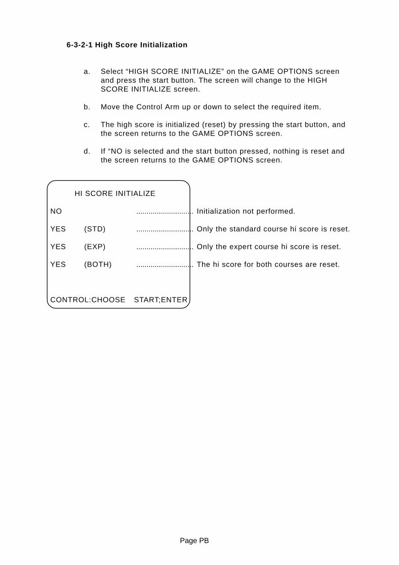
6-3-2-1 High Score Initialization
a. Select “HIGH SCORE INITIALIZE” on the GAME OPTIONS screenand press the start button. The screen will change to the HIGHSCORE INITIALIZE screen.
b. Move the Control Arm up or down to select the required item.
c. The high score is initialized (reset) by pressing the start button, andthe screen returns to the GAME OPTIONS screen.
d. If “NO is selected and the start button pressed, nothing is reset andthe screen returns to the GAME OPTIONS screen.
HI SCORE INITIALIZE
NO ............................ Initialization not performed.
YES (STD) ............................ Only the standard course hi score is reset.
YES (EXP) ............................ Only the expert course hi score is reset.
YES (BOTH) ............................ The hi score for both courses are reset.
CONTROL:CHOOSE START;ENTER

Page 25
6-3-3 I/O Test
a. Select item (3) “I/O TEST” on the menu screen.
b. Move the Control Arm up or down to select the required item.
c. Press the start button to enter the selected test.
d. Select “EXIT” and press the start button to return to the menu screen
I/O TEST
DIP 12345678 .................................... (a)
SWITCH TEST .................................... (b)
AIR SPRING TEST .................................... (c)
EXIT
CONTROL:CHOOSE START:ENTER
(a) Displays the state of the PCB Dip switches, when a switch is ON the
number is shown in red.
(b) Tests the switches and control potentiometers. (See 6-3-3-1.)
(c) Tests the air spring. (See 6-3-3-2.)
Page PB
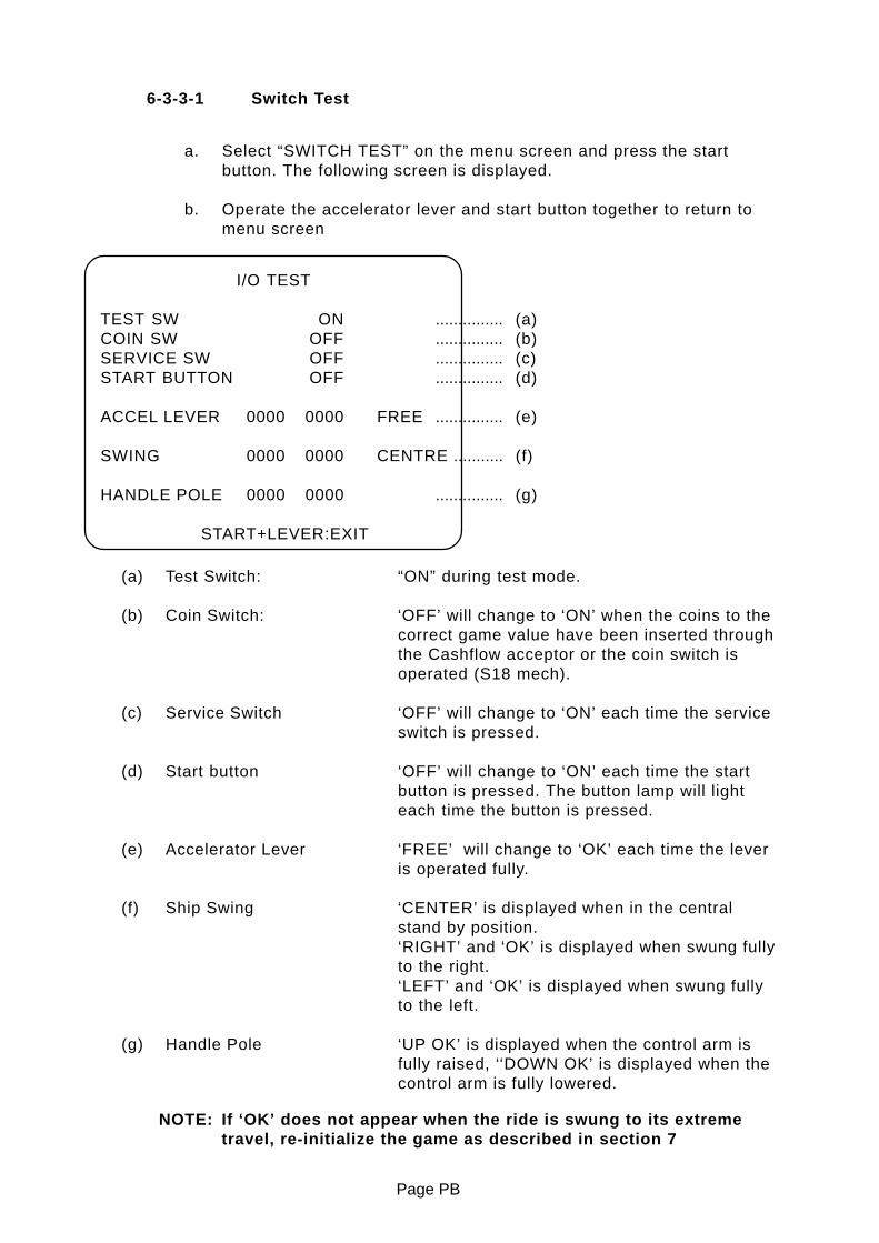
6-3-3-1 Switch Test
a. Select “SWITCH TEST” on the menu screen and press the startbutton. The following screen is displayed.
b. Operate the accelerator lever and start button together to return tomenu screen
I/O TEST
TEST SW ON ............... (a)COIN SW OFF ............... (b)SERVICE SW OFF ............... (c)START BUTTON OFF ............... (d)
ACCEL LEVER 0000 0000 FREE ............... (e)
SWING 0000 0000 CENTRE ........... (f)
HANDLE POLE 0000 0000 ............... (g)
START+LEVER:EXIT
(a) Test Switch: “ON” during test mode.
(b) Coin Switch: ‘OFF’ will change to ‘ON’ when the coins to thecorrect game value have been inserted throughthe Cashflow acceptor or the coin switch isoperated (S18 mech).
(c) Service Switch ‘OFF’ will change to ‘ON’ each time the serviceswitch is pressed.
(d) Start button ‘OFF’ will change to ‘ON’ each time the startbutton is pressed. The button lamp will lighteach time the button is pressed.
(e) Accelerator Lever ‘FREE’ will change to ‘OK’ each time the leveris operated fully.
(f) Ship Swing ‘CENTER’ is displayed when in the centralstand by position.‘RIGHT’ and ‘OK’ is displayed when swung fullyto the right.‘LEFT’ and ‘OK’ is displayed when swung fullyto the left.
(g) Handle Pole ‘UP OK’ is displayed when the control arm isfully raised, ‘‘DOWN OK’ is displayed when thecontrol arm is fully lowered.
NOTE: If ‘OK’ does not appear when the ride is swung to its extremetravel, re-initialize the game as described in section 7
Page 27
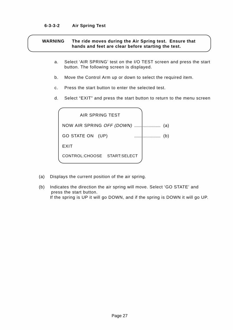
6-3-3-2 Air Spring Test
WARNING The ride moves during the Air Spring test. Ensure thathands and feet are clear before starting the test.
a. Select ‘AIR SPRING’ test on the I/O TEST screen and press the startbutton. The following screen is displayed.
b. Move the Control Arm up or down to select the required item.
c. Press the start button to enter the selected test.
d. Select “EXIT” and press the start button to return to the menu screen
AIR SPRING TEST
NOW AIR SPRING OFF (DOWN) ...................... (a)
GO STATE ON (UP) ...................... (b)
EXIT
CONTROL:CHOOSE START:SELECT
(a) Displays the current position of the air spring.
(b) Indicates the direction the air spring will move. Select ‘GO STATE’ andpress the start button.If the spring is UP it will go DOWN, and if the spring is DOWN it will go UP.

Page PB
MONITOR TEST
GRADATION PATTERNCROSSHATCH PATTERN [CRT]CROSSHATCH PATTERN [PROJECTOR]WHITE WINDOW [H]WHITE WINDOW [M]WHITE WINDOW [L]INTERLACE PATTERNVIEW ANGLE ADJUST [CRT]VIEW ANGLE ADJUST [PROJECTOR]FULL WHITE
EXIT
CONTROL:CHOOSE START:ENTER
6-3-4 Monitor Test
a. Select “MONITOR TEST” on the menu screen and press the startbutton. The following screen is displayed.
b. Select an item by moving the control arm up or down. When the startbutton is pressed the screen will change to the selected pattern.
c. To return to MONITOR TEST screen from a test pattern, press thestart button.
d. Select “EXIT” and press the start button to return to the menu screen

Page 29
6-3-5 Sound Test
a. Select “SOUND TEST ” on the menu screen and press the startbutton. The following screen is displayed.
b. Move the Control Arm up or down to select the required item.
c. Press the start button to enter the selected test.
d. Move the control arm up or down to alter the setting of theselected item.
d. Select “EXIT” and press the start button to return to the menuscreen
SOUND TEST`[DEFAULT IN GREEN]
GAME VOLUME FRONT SP 2C .................... (a)TANK SP 2C ............... (b)
ATTRACT VOLUME 2C .................... (c)
REQUEST SONG NO. 001 .................... (d)
MESSAGE
EXIT
CONTROL:CHOOSE START:ENTER
The selected songdescription is displayed
.........
(a) Front speaker volume Adjusts the volume of speakers in the header.
(b) Tank speaker volume Adjusts the volume of the tank speaker on theride.
(c) Attraction volume Adjusts the volume during attract mode.
(d) Sound selection Each digit of the REQUEST SONG No. can bechanged by moving the control arm up ordown. Each number will produce a differenttune or sound when the start button is pressed.001 will produce a stereo test. First a tone willbe produced from the front speakers, then fromthe tank speaker and then from all speakers.

Page PB
6-3-6 ADS Data
Select “ADS DATA ” on the menu screen and press the start button.
The book keeping data for the game will be displayed.
6-3-7 Others
Select “OTHERS” on the menu screen and press the start button.
This screen is used to test the PCB and to reset the game to factorysettings.

Page 31
7 INITIALIZATION
Adjustments When Replacing Parts (Initialization)
The following adjustments should always be performed after replacing thegame PC board, ROM, or Control Pots.The game will not operate correctly if these adjustments are not made.
a) Ensure that Control Handle assembly and Ride assembly are in the
neutral stand-by position.
b) Slide the test switch “ON” while pressing the service switch. The following
screen will be displayed on the monitor.
VOLUME INITIALIZE
TEST SW ONCOIN SW OFFSERVICE SW OFFSTART BUTTON OFF
ACCEL LEVER 0000 0000SWING 0000 0000 CENTREHANDLE POLE 0000 0000 UP
START:HANDLE POLE ADJUST
c) At this time the Ride assembly and Accelerator lever are initialized.
d) Press the start button to initialize the Control Arm. The following screen
will be displayed.
e) Move the Control Arm UP and DOWN through its full range of movement.
This motion will be registered as the motion range of the Control Arm.
f) Slide the test switch “OFF” to return to normal game mode.
HANDLE POLE ADJUST
UP DOWNHANDLE POLE 0000 0000
PLEASE MAKE HANDLE POLEUPDOWN TO ADJUST!

Page PB
8. REMOVING AND REPLACING ASSEMBLIES AND PARTS.
WARNING
• Adjustments or maintenance on this machine should be carried out byqualified personnel only.
• Do not make any alterations to this machine without prior approval. Doingso could cause unforeseeable danger.
• Only parts specified by Namco Europe Ltd. should be used when replacingor repairing parts (including screws).
• Ensure that power to the machine is turned OFF before commencing anymaintenance work (troubleshooting, repairs etc.)
• If performing work not described in this manual, be sure to contact yourdistributor for instructions as no responsibility will be accepted fordamage or injury.
• Parts of the power supply, projector monitor and air compressor remainhot or carry high voltage even after switching OFF and could cause burnsor electric shock. Take care not to touch these parts accidentally.
• Make sure that the machine is switched OFF before connecting ordisconnecting any plugs or connectors.
• When removing the mains connector from the machine, or the mains plugfrom the wall outlet, always grasp the plug not the cable.
8-1 COMPRESSOR ASSEMBLY
NOTE:
There are no user serviceable parts on the compressor assembly .
Under no circumstances should any regulator valves be adjusted.Altering the regulator valves could lead to serious damage to the systemor injury to personnel
WARNING
• Parts of the compressor become very hot during use. Take care not totouch the compressor when it is hot.

Page 33
8-2 Ride Assembly
8-2-1 Replacing the Swing Potentiometer
WARNING • Make sure that the power is turned OFF beforecommencing any work.
• Do not let any one get on the ride assembly whilereplacing the potentiometer to prevent injury bytrapped hands or fingers.
1) Remove the two pozi head screws (with flat and springwashers)(M5x10) and remove the potentiometer cover.
2) Remove the two pozi head screws (with flat and springwashers)(M5x10) and remove the maintenance cover.
3) Disconnect the connector. Loosen the grub screw (M4x12) andremove the potentiometer complete with its mounting bracket.

Page PB
4) Remove the potentiometer from the mounting bracket and replacewith a new potentiometer.
5) Re-assemble in reverse order.
NOTE: When refitting the potentiometer and bracket ensure that the grubscrew engages on the flat of the potentiometer shaft, and thenotch in the mounting bracket engages on the pin.
6) Re-initialize the game. (Refer to section 7 ‘Initialization’)
8-2-2 Removing the Tank
WARNING • Make sure that the power is turned OFF beforecommencing any work.
1) Remove the four security screws (M5x12) and four security screws(M5x20), and remove the tank.
2) Re-assemble in reverse order.

Page 35
8-2-3 Replacing Solenoid Valve A
WARNING • Make sure that the power is turned OFF beforecommencing any work.
1) Remove the tank. (Refer to section 8-2-2 ‘Removing the Tank’
2) Disconnect the connector.
3) Push the blue release of the elbow union in, and while holding it in,pull out the air tube. (There will be a loud noise as the air pressure isreleased.)
4) Remove the two pozi head screws (M4x35) and remove the solenoidvalve A.
5) Remove the elbow union, half union and silencer from the removedsolenoid valve, and install them on to the new solenoid valve.
6) Re-assemble in reverse order. (The air tube is just a push fit.)
NOTE:• Take care that no dirt or other matter gets in to the air tube while
it is disconnected.• After refitting the air tube, give it a gentle pull to ensure that it is
connected properly and will not come loose.

Page PB
8-2-4 Replacing Solenoid Valve B
WARNING • Make sure that the power is turned OFF beforecommencing any work.
1) Remove the tank. (Refer to section 8-2-2 ‘Removing the Tank’
2) Disconnect the connector.
3) Push the blue release of the elbow union in, and while holding it in,pull out the air tube. (There will be a loud noise as the air pressure isreleased.)
4) Remove the two pozi head screws (M4x35) and remove the solenoidvalve B.
5) Remove the half union, taper-screw plug and silencer from theremoved solenoid valve, and install them on to the new solenoidvalve.
6) Re-assemble in reverse order. (The air tube is just a push fit.)
NOTE:• Take care that no dirt or other matter gets in to the air tube while
it is disconnected.• After refitting the air tube, give it a gentle pull to ensure that it is
connected properly and will not come loose.

Page 37
8-3 Control Arm Assembly
8-3-1 Replacing the Accelerator Potentiometer
WARNING • Make sure that the power is turned OFF beforecommencing any work.
1) Remove the four security screws (M5x12) and remove the acceleratorcover.
3) Disconnect the connector. Loosen the grub screw (M3x5) and removethe potentiometer complete with its mounting bracket.
4) Remove the potentiometer from the mounting bracket and replacewith a new potentiometer.
5) Re-assemble in reverse order.
NOTE: When refitting the potentiometer and bracket ensure that the grubscrew engages on the flat of the potentiometer shaft, and thewire harness is secured with the two cord grips so that it does notget caught or pinched by the moveable section.
6) Re-initialize the game. (Refer to section 7 ‘Initialization’)

Page PB
8-3-2 Replacing the Control Arm Potentiometer
WARNING • Make sure that the power is turned OFF beforecommencing any work.
1) Remove the tank. (Refer to section 8-2-2 ‘Removing the Tank’).
3) Disconnect the connector. Loosen the grub screw (M4x5) and removethe potentiometer complete with its mounting bracket.
4) Remove the potentiometer from the mounting bracket and replacewith a new potentiometer.
5) Re-assemble in reverse order.
NOTE: When refitting the potentiometer and bracket ensure that the grubscrew engages on the flat of the potentiometer shaft, and the lugon the mounting bracket engages in the slot of the mainmetalwork.
6) Re-initialize the game. (Refer to section 7 ‘Initialization’)

Page 39
8-3-3 Replacing the Start Switch or Lamp
WARNING • Make sure that the power is turned OFF beforecommencing any work.
1) Remove the eight security screws (M5x12) and lift the top vac-formsufficiently to remove the switch and lamp from the push button.
2) Remove the top vac-form.
3) Replace the lamp or switch.
4) Re-assemble in reverse order.

Page PB
8-4 Header Assembly
8-4-1 Replacing the Fluorescent Lamp or Starter
WARNING • Make sure that the power is turned OFF beforecommencing any work.
WARNING • The Header Assembly is very high, and it is importantthat a means of reaching the height safely, withoutstretching, is available. (e.g. steps, step stools etc.)
WARNING • The fluorescent lamp may be hot, take care whenhandling.
1) Remove the four security screws (M5x20), and remove the acrylicsign board.
2) Replace the fluorescent lamp or starter.
3) Re-assemble in reverse order.

Page 41
9. PARTS
ITEM DESCRIPTION PART No
1 HEADER CABINET 37100110
2 LOUDSPEAKER GRILLE 46000083
4 HEADER ACRYLIC 30000234
5 ACRYLIC RETAINING BRACKET 46000084
E1 FLOURESCENT TUBE 18" 15W 64500009
E3 LOUDSPEAKER 5½" FULL RANGE 62000065
E4 STARTER 240v 4-80W UNIVERSAL 63000000
E5 STARTER HOLDER 64800001
B1
M6x16 HEX HEAD SET SCREW - BZP 26500311
M6 SPRING WASHER - BZP 28000028
M6 FLAT WASHER - BZP 28000166
B2
M4x16 PZ PAN HEAD - BLACK 26300294
M4 SPRING WASHER - BLACK 28000127
M4 FLAT WASHER - BLACK 28000132
B3 M5x20 SECURITY BUTTON HEAD - SUS 26300039
B6 No4x½" PZ PAN HEAD WOODSCREW - BZP 26100070
B7 M4x12 PZ PAN HEAD - BZP 26300057
B8 M4x16 PZ PAN HEAD - BZP 26300383
B9 M4 WHIZZTITE NUT - YEL ZNC 27000128
Header Assy

Page 42
Coin Tower
ITEM DESCRIPTION PART No
1 COIN TOWER TOP VAC-FORM 46000057
2 INSTRUCTION DECAL SUPPORT BRACKET 46000146
3 PLAY INSTRUCTION DECAL - ACRYLIC 30000235
5 WOODEN CASHBOX 37100093
6 M12 ADJUSABLE FOOT 88300311
7 3.5-6v METER - PANEL MOUNT 65000002
8 MINIATURE SLIDE SWITCH - DPCO 60000023
9 SERVICE SWITCH 7mm RED - F424 60000059
B1 No8x½" PZ CSK WOODSCREW - BZP 26100265
B2 M3x10 PZ PAN HEAD - BZP 26300067
B7 M5x16 SECURITY BUTTON HEAD - SUS 26300032
B8 M5x20 SECURITY BUTTON HEAD - SUS 26300039
B9 M5x14 RAWLNUT 27000153

Page 43
Cabinet Base
ITEM DESCRIPTION PART No
1 INTERLOCK SWITCH 6000006
2 INTERLOCK SWITCH COVER 39000028
3 SCHAFFNER 10A DOUBLE FUSED MAINS IN FILTER 62500011
4 SHAFFNER BOOT 1B3 66000017
5 10A 20mm FUSE 63500705
6 SWIVEL CASTOR 75mm 59000005
7 M16 ADJUSTABLE FOOT 88300079
8 CONDENSATE BOTTLE 0.5ltr 46000079
9 WOODEN BLANKING STRIP 37100109
10 AQUA JET SUPER SYSTEM 22 PCB ASSY XAJ-PCB
11 4 CHANNEL AMP PCB - SUPER SYSTEM 22 XCYB-AMPCB
12 LAMP DRIVER PCB - SINGLE CHANNEL 46000020
13 3 CHANNEL AMPLIFIER - Ver3 46000036
14 ASTEC SA301-3400 SMPSU 5v 30A 83000001
ITEM DESCRIPTION PART No
15 FUSE - 1¼" 1A QB 63500424
16 COMPRESSOR ASSY - TYPE 600 W/LOW READ GAUGE 46000058
17 FAN 230v 4½" 67000015
18 ROTARY FAN 45000940
19 PLASTIC STARTER CAPACITOR 46000041
20 SSR 46000164
B1 M5x20 PZ PAN HEAD - BZP 26300576
M5 SPRING WASHER - BZP 28000145
M5 FLAT WASHER - BZP 28000144
B2 M4x20 PZ PAN HEAD - BZP 26300055
M4 SPRING WASHER - BZP 28000035
M4 FLAT WASHER - BZP 28000036
B3 M8x25 HEX HEAD SET SCREW - BZP 26300050
M8 SPRING WASHER - BZP 28000176
M8 FLAT WASHER - BZP 28000175
B4 M5x30 PZ PAN HEAD - BZP 26300595

Page 44
ITEM DESCRIPTION PART No
1 PIONEER REAR PROJECTION MONITOR 230v 84000028
2 CABINET FRONT PANEL 37100106
3 LOUDSPEAKER GRILLE 45000701
4 HARNESS CONNECTOR BRACKET 46000082
5 ADJUSTABLE FOOT MOUNTING BRACKET 45000204
6 SIDE DECAL - LHS/RHS 40000381
7 FAN 4½" 230v 67000015
8 FRONT DECAL 40000383
9 LOUDSPEAKER 6½" - BASS 62000068
B1 M5x30 SECURITY BUTTON HEAD - SUS 26300036
B2
M5x25 PZ PAN HEAD - BZP 26300049
M5 SPRING WASHER - BZP 28000144
M5 FLAT WASHER - BZP 28000145
B3
M10x130 HEX HEAD SET SCREW - BZP 26500475
M10 SPRING WASHER - BZP 28000023
PIONEER CLAMP WASHER 46000163
Cabinet

Page 45
ITEM DESCRIPTION PART No
1 CONTROL ARM TOP VAC-FORM 46000054
2 NAMCO DECAL 40000390
3 AQUAJET DECAL 40000389
4 ACCELERATOR DECAL 40000392
5 HANDLEBAR COVER VAC-FORM 46000055
6 CONTROL ARM BOTTOM VAC-FORM 46000053
7 RPB RECTANGULAR PUSH BUTTON - YELLOW "START" 60500044
8 START DECAL 40000391
9 WARNING DECAL 40000393
10 HANDLEBAR GRIP - LHS/RHS 46000141
B1 M5x16 SECURITY BUTTON HEAD - SUS 26300032
Control Arm

Page 46
ITEM DESCRIPTION PART No
2 RUBBER STOPPER RI-30 46000007
3 PITCH SPRING BUMPER 46000075
4 PITCH SPRING 46000073
5 PITCH STOPPER RUBBER BLOCK 46000072
6 PITCH POTENTIOMETER MOUNTING BRACKET 46000132
7 PITCH POTENTIOMETER X008-021
8 BEARING UCP-206-NSK 46000080
9 SPRING SLEEVE 46000131
10M16 FULL NUT - BZP 27000205
M16 SPRING WASHER - BZP 28000301
11 BEARING SECURING WASHER 40 OD x 17 ID x 3.2T 46000133
12 BEARING SPACER 46000130
13 PITCH MAIN SHAFT 46000129
B1
M4x12 PZ PAN HEAD - BZP 26300057
M4 SPRING WASHER - BZP 28000035
M4 FLAT WASHER - BZP 28000036
B3 M4x8 HEX SOCKET SET SCREW - BZP 26300083
B4
M14x50 HEX HEAD SET SCREW - BZP 26500502
M14 SPRING WASHER - BZP 28000302
M14 FLAT WASHER - BZP 28000021
B5 M8x20 SOCKET HEAD CSK SCREW - BZP 26300862

Page 47
ITEM DESCRIPTION PART No
11 HANDLEBAR METALWORK 46000134
12 ACCELERATOR PLATE 46000135
13 ACCELERATOR POTENTIOMETER SHAFT 46000136
14 ACCELERATOR POTENTIOMETER BRACKET 46000137
15 ACCELERATOR SPRING STOP PIN 46000138
16 ACCELERATOR LIMIT STOP TUBE 46000139
17 ACCELERATOR LIMIT STOP BUMPER 46000074
18 ACCELERATOR SPRING 46000157
19 ACCELERATOR SLIDE COVER 46000140
25 ACCELERATOR HANDLE 46000076
27 SPACER - 8mm OD x 3mm LONG 46000142
29 OILITE BUSHING LFF 0705 46000077
30 OILITE BUSHING LFF 1012 46000078
E4 ACCELERATOR POTENTIOMETER X008-021
B7 M3x5 HEX SOCKET SET SCREW - BZP 26300111
B10 M5 WHIZZTITE NUT - BZP 27000151
B15
M5x8 PZ PAN HEAD - BZP 26300570
M5 SPRING WASHER - BZP 28000144
3/16" x 3/4" FLAT WASHER - BZP 28000224
Accelerator
Page 48
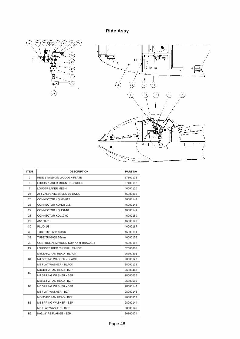
ITEM DESCRIPTION PART No
2 RIDE STAND-ON WOODEN PLATE 37100111
5 LOUDSPEAKER MOUNTING WOOD 37100112
6 LOUDSPEAKER MESH 46000120
24 AIR VALVE VK334-6GS-01 12vDC 46000069
25 CONNECTOR KQL08-01S 46000147
26 CONNECTOR KQH08-01S 46000148
27 CONNECTOR KQU08-10 46000149
28 CONNECTOR KQL10-00 46000150
29 AN103-01 46000126
30 PLUG 1/8 46000167
32 TUBE TU1065B 50mm 46000151
33 TUBE TU0805B 55mm 46000155
38 CONTROL ARM WOOD SUPPORT BRACKET 46000162
E2 LOUDSPEAKER 5½" FULL RANGE 62000065
B1
M4x20 PZ PAN HEAD - BLACK 26300391
M4 SPRING WASHER - BLACK 28000127
M4 FLAT WASHER - BLACK 28000132
B2M4x40 PZ PAN HEAD - BZP 26300443
M4 SPRING WASHER - BZP 28000035
B3
M5x16 PZ PAN HEAD - BZP 26300580
M5 SPRING WASHER - BZP 28000144
M5 FLAT WASHER - BZP 28000145
B5
M5x35 PZ PAN HEAD - BZP 26300613
M5 SPRING WASHER - BZP 28000144
M5 FLAT WASHER - BZP 28000145
B9 No6x½" PZ FLANGE - BZP 26100074
Ride Assy

Page 49
ITEM DESCRIPTION PART No
1 RIDE STAND-ON METAL BASE 46000117
3 SIDE VAC-FORM SUPPORT BRACKET - LHS 46000118
4 SIDE VAC-FORM SUPPORT BRACKET - RHS 46000119
8 SIDE VAC-FORM MOUNTING BRACKET 46000122
10 REAR VAC-FORM CLOSING BRACKET 46000124
31 TUBE TU1065-B 46000151
B1
M8x20 HEX HEAD SET SCREW - BZP 88300700
M8 SPRING WASHER - BZP 28000176
M8 FLAT WASHER - BZP 28000175
B3
M5x16 PZ PAN HEAD - BZP 26300580
M5 SPRING WASHER - BZP 28000144
M5 FLAT WASHER - BZP 28000145
B4
M5x25 PZ PAN HEAD - BZP 26300049
M5 SPRING WASHER - BZP 28000144
M5 FLAT WASHER - BZP 28000145
B10
M4x10 PZ PAN HEAD - BZP 26300366
M4 SPRING WASHER - BZP 28000035
M4 FLAT WASHER - BZP 28000036

Page 50
ITEM DESCRIPTION PART No
7 FRONT VAC-FORM MOUNTING BRACKET 46000121
11 LOWER VAC-FORM - RHS 46000049
12 LOWER VAC-FORM - LHS 46000048
13 UPPER STANDING AREA VAC-FORM 46000050
14 REAR VAC-FORM 46000051
15 TOP FRONT VAC-FORM 46000052
16 REAR EXHAUST DECAL 40000384
17 SIDE FLASH DECAL - LHS UPPER 40000385
18 SIDE FLASH DECAL - RHS UPPER 40000386
19 SIDE FLASH DECAL - LHS LOWER 40000387
20 SIDE FLASH DECAL - RHS LOWER 40000388
21 3M ANTI SLIP FLOOR MAT - STANDING AREA 46000070
22 FRONT VAC-FORM CLOSING BRACKET 46000125
35 SUPERVISION WARNING DECAL 40000396
B6M5x16 SECURITY BUTTON HEAD - SUS 26300032
M5 FLAT WASHER- SUS 28000015
B7 M5x25 SECURITY BUTTON HEAD - SUS 26300033
B8 M5x14 RAWLNUT 27000153
Ride Vac-Forms and Decals

Page 51
ITE
MD
ES
CR
IPT
ION
PA
RT
No
7M
AIN
FLO
OR
SID
E C
OV
ER
- R
HS
4600
0093
8M
AIN
FLO
OR
SID
E C
OV
ER
- L
HS
4600
0092
22A
IR S
PR
ING
MO
UN
TIN
G B
RA
CK
ET
- U
PP
ER
4600
0017
333M
AN
TI S
LIP
FLO
OR
MA
T -
RE
AR
BA
SE
4600
0071
34B
AS
E W
AR
NIN
G D
EC
AL
4000
0394
36C
ON
NE
CT
OR
KQ
L10-
U02
4600
0161
B3
M5x
16 S
EC
UR
ITY
BU
TT
ON
HE
AD
- S
US
2630
0032
B10
3/8"
x3/4
" H
EX
HE
AD
SE
T S
CR
EW
- B
ZP
2650
0901
PA
RT
S N
OT
SH
OW
N
RU
BB
ER
SK
IRT
- L
HS
4600
0168
RU
BB
ER
SK
IRT
- R
HS
4600
0169
RU
BB
ER
SK
IRT
FIX
ING
PLA
TE
- B
AS
E46
0001
70
RU
BB
ER
SK
IRT
FIX
ING
PLA
TE
- R
IDE
4600
0171
Ride Base Assy

Page 52
ITE
MD
ES
CR
IPT
ION
PA
RT
No
2R
IDE
BA
SE
4600
0087
21S
TE
ER
ING
AR
M M
OU
NT
ING
BR
AC
KE
T46
0001
06
40R
UB
BE
R S
TO
PP
ER
- R
I/65/
HD
4600
0059
41R
UB
BE
R S
TO
PP
ER
- R
I-30
4600
0007
42A
IR S
PR
ING
4600
0060
44LI
NK
BA
LL -
TB
S12
4600
0062
46S
HO
CK
AB
SO
RB
ER
- F
K/2
530/
S/N
M1
4600
0064
47S
IDE
LO
AD
AD
AP
TO
R -
KG
/001
/NM
4600
0065
B6
M10
x25
HE
X H
EA
D S
ET
SC
RE
W -
BZ
P26
5001
34
M10
SP
RIN
G W
AS
HE
R -
BZ
P28
0000
23
M10
FLA
T W
AS
HE
R -
BZ
P28
0001
98
B10
3/8"
x 1
3/1
6" H
EX
HE
AD
SE
T S
CR
EW
- B
ZP
2650
0902
3/8"
SP
RIN
G W
AS
HE
R -
BZ
P28
0002
13
3/8"
FLA
T W
AS
HE
R -
HE
AV
Y D
UT
Y -
BZ
P28
0002
14
B14
M12
NY
LOC
NU
T -
BZ
P27
0002
01
M12
FLA
T W
AS
HE
R -
BZ
P28
0000
20

Page 53
ITE
MD
ES
CR
IPT
ION
PA
RT
No
1M
AIN
FLO
OR
BA
SE
4600
0086
3R
OS
TA
SP
RIN
G S
HA
FT
MO
UN
TIN
G A
SS
Y46
0000
88
5Y
AW
DR
IVE
SH
AF
T46
0000
90
9Y
AW
ME
CH
AN
ICA
L S
TO
PP
ER
MN
TG
BR
AC
KE
T46
0000
94
26H
AR
DE
NE
D B
LOC
K46
0001
08
38S
WIV
EL
CA
ST
OR
75m
m59
0000
05
39A
DJU
ST
AB
LE F
OO
T M
20x7
046
0001
60
B1
M4x
12 P
Z P
AN
HE
AD
- B
ZP
2630
0336
M4
SP
RIN
G W
AS
HE
R -
BZ
P28
0000
35
M4
FLA
T W
AS
HE
R -
BZ
P28
0000
36
B4
M6x
16 H
EX
HE
AD
SE
T S
CR
EW
- B
ZP
2650
0311
M6
SP
RIN
G W
AS
HE
R -
BZ
P28
0000
28
M6
FLA
T W
AS
HE
R -
BZ
P28
0000
37
B5
M8x
30 H
EX
HE
AD
SE
T S
CR
EW
- B
ZP
2650
0407
M8
SP
RIN
G W
AS
HE
R -
BZ
P28
0001
76
M8
FLA
T W
AS
HE
R -
BZ
P28
0001
75
B6
M10
x25
HE
X H
EA
D S
ET
SC
RE
W -
BZ
P26
5001
34
M10
SP
RIN
G W
AS
HE
R -
BZ
P28
0000
23
M10
FLA
T W
AS
HE
R -
BZ
P28
0001
98
ITE
MS
NO
T S
HO
WN
"FO
RK
HE
RE
" D
EC
AL
4000
0072
BA
SE
SID
E W
AR
NIN
G D
EC
AL
4000
0394

Page 54
ITE
MD
ES
CR
IPT
ION
PA
RT
No
10R
OS
TA
SP
RIN
G M
OU
NT
ING
SH
AF
T46
0000
95
13LI
NK
BA
LL M
OU
NT
ING
SH
AF
T46
0000
98
17R
OS
TA
SP
RIN
G R
ET
AIN
ING
WA
SH
ER
4600
0102
18R
OS
TA
SP
AC
ER
WA
SH
ER
4600
0103
19R
OS
TA
RE
TA
ININ
G B
RA
CK
ET
4600
0104
32R
OS
TA
SP
RIN
G R
EA
R P
AC
KIN
G B
RA
CK
ET
4600
0114
45R
OD
EY
E -
RB
L16B
D46
0000
63
48R
OS
TA
SP
RIN
G D
R-S
-27x
6046
0000
67
49B
EA
RIN
G -
UC
PA
/204
/FY
H46
0000
68
B8
M16
x40
SO
CK
ET
HE
AD
CA
P S
CR
EW
- B
ZP
2650
0602
B9
M6x
16 H
EX
HE
AD
SE
T S
CR
EW
- B
ZP
2650
0311
M6
SP
RIN
G W
AS
HE
R -
BZ
P28
0000
28
M6
FLA
T W
AS
HE
R -
BZ
P28
0000
37
B13
M12
x25
CS
K C
AP
SC
RE
W -
BZ
P26
3009
40
B14
M12
FU
LL N
UT
- B
ZP
2700
0022
B17
M12
SP
RIN
G W
AS
HE
R -
BZ
P28
0000
19
B19
M12
FLA
T W
AS
HE
R -
BZ
P28
0000
20

Page 55
ITE
MD
ES
CR
IPT
ION
PA
RT
No
4D
IST
RIB
UT
ION
BO
X46
0000
89
6M
AIN
FR
ON
T J
OIN
T B
OX
4600
0091
12M
AIN
FR
ON
T J
OIN
T B
OX
CO
VE
R46
0000
97
15B
EA
RIN
G E
ND
SP
AC
ER
4600
0100
16R
IDE
AS
SE
MB
LY J
OIN
T T
UB
E M
OU
NT
ING
BR
AC
KE
T46
0001
01
20Y
AW
PO
TE
NT
IOM
ET
ER
MO
UN
TIN
G B
RA
CK
ET
4600
0105
21Y
AW
PO
TE
NT
IOM
ET
ER
X00
8-02
1
27Y
AW
PO
T A
CC
ES
S P
LAT
E46
0001
09
28Y
AW
PO
TE
NT
IOM
ET
ER
CLO
SIN
G B
RA
CK
ET
4600
0110
43S
PH
ER
ICA
L B
EA
RIN
G -
PB
22
4600
0061
51T
UB
E -
TU
O80
5B46
0001
55
B1
M4x
10 P
Z P
AN
HE
AD
- B
ZP
2630
0366
M4
SP
RIN
G W
AS
HE
R -
BZ
P28
0000
35
M4
FLA
T W
AS
HE
R -
BZ
P28
0000
36
B2
M5x
16 P
Z P
AN
HE
AD
- B
ZP
2630
0580
M5
SP
RIN
G W
AS
HE
R -
BZ
P28
0000
32
M5
FLA
T W
AS
HE
R -
BZ
P28
0001
45
B3
M5x
16 S
EC
UR
ITY
BU
TT
ON
HE
AD
- B
ZP
2630
0032
B6
M10
x25
HE
X H
EA
D S
ET
SC
RE
W -
BZ
P26
5001
34
M10
SP
RIN
G W
AS
HE
R -
BZ
P28
0000
23
M10
FLA
T W
AS
HE
R -
BZ
P28
0001
98
B7
M4x
8 H
EX
SO
CK
ET
SE
T S
CR
EW
- B
ZP
2630
0083
B9
M6x
16 H
EX
HE
AD
SE
T S
CR
EW
- B
ZP
2650
0311
M6
SP
RIN
G W
AS
HE
R -
BZ
P28
0000
28
M6
FLA
T W
AS
HE
R -
BZ
P28
0000
37
B15
M16
FU
LL N
UT
- B
ZP
2700
0205
M16
SP
RIN
G W
AS
HE
R -
BZ
P28
0003
01
M16
FLA
T W
AS
HE
R -
BZ
P28
0002
40

Page 56
Page 57
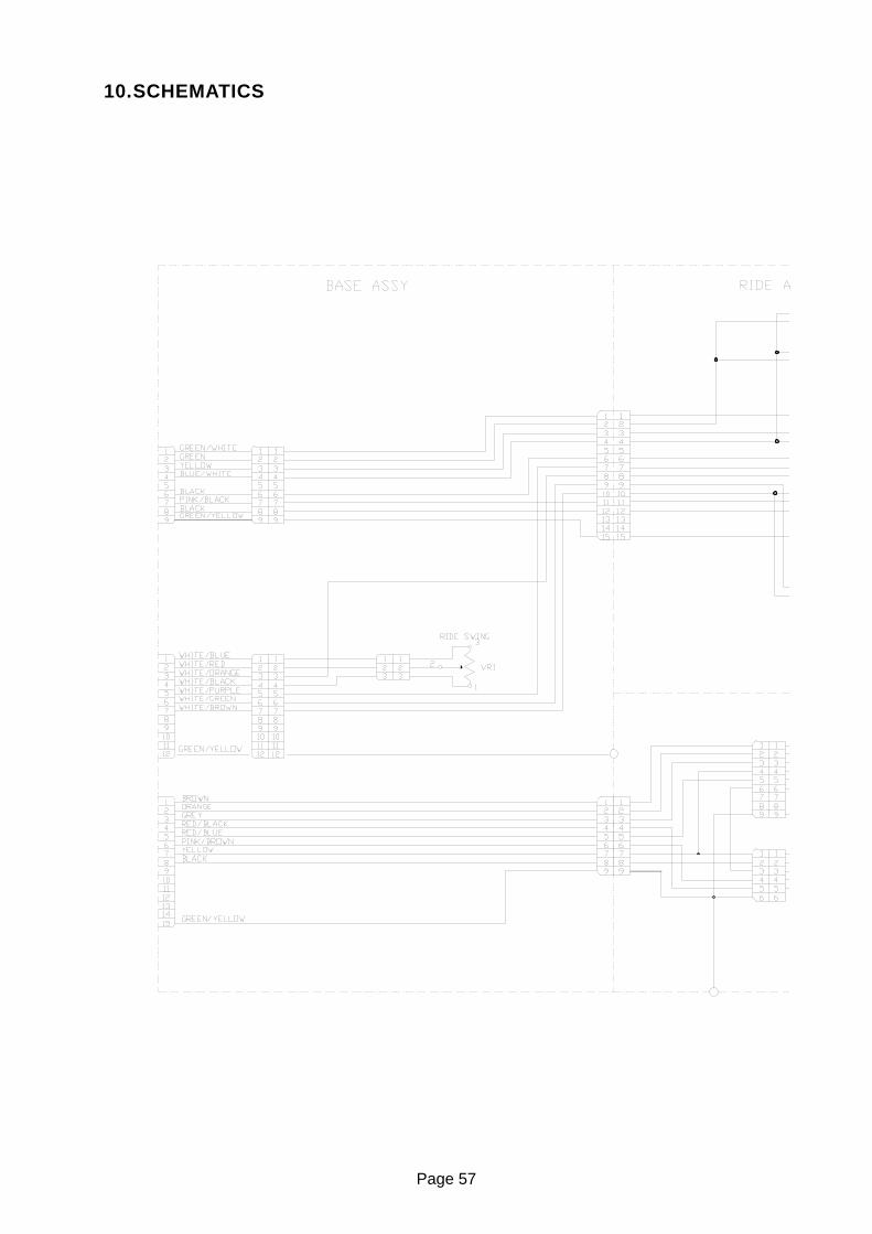
10.SCHEMATICS

Page 58

Page 59

Page 60
Top Related