


Languages
Pages
Legal

Operational Best Practices for “ESP Performance Improvement “.
By
Susanta Ghosh AGM(O)I/C & R.N.Das AGM(O) TSTPS-Kaniha .
TSTPS /KANIHA
6X500 MW UNITS , TSTPS , KANIHA
2
2ND LARGEST THERMAL POWER PLANT OF NTPC
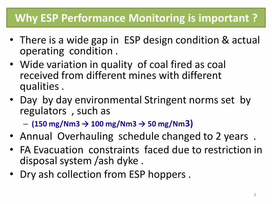
Why ESP Performance Monitoring is important ?
• There is a wide gap in ESP design condition & actual operating condition .
• Wide variation in quality of coal fired as coal received from different mines with different qualities .
• Day by day environmental Stringent norms set by regulators , such as – (150 mg/Nm3 → 100 mg/Nm3 → 50 mg/Nm3)
• Annual Overhauling schedule changed to 2 years . • FA Evacuation constraints faced due to restriction in
disposal system /ash dyke . • Dry ash collection from ESP hoppers .
3

ESP DESIGN DETAILS .
4
SL
NO PARAMETERS Unit STAGE-I STAGE- II
1 Unit Capacity MW 2X500 MW 4x500 MW
2 Coal Consumption /
Unit T/HR
336 - DESIGN
370 - WORST
420 - SITE RESTRICTION
336 - DESIGN
370 - WORST
420 - SITE RESTRICTION
3 Ash % 44% 44%
4 FG flow volume M 3/SEC 789.00 777.0( 533.48 Nm3/sec)
5 Inlet dust burden Gm/Nm3 60 81.303 ( Guran- 63.387)
6 Outlet dust burden mg/Nm3 56 20.0
7 Efficiency % 99.91 99.939 ( 99.97)
8 Gas inlet Temp 0C 134 140 (125)

FA SYSTEM DESIGN DATA .
5
SL
NO PARAMETERS Unit STAGE-I STAGE- II
1 Unit Capacity MW 2X500 MW 4x500 MW
2 Coal Consumption /
Unit T/HR
336 - DESIGN
370 - WORST
420 - SITE RESTRICTION
336 - DESIGN
370 - WORST
420 - SITE RESTRICTION
3 FA Evacuation SYSTEM *** Continuous , Vacuum
Ext Type
Continuous , Vacuum Ext
Type
4 Dry ash facility *** 25 % each unit
Silo 135 Ton capacity
Two Units full collection
with one unit
transportation
Buffer Hopper 120 X8 tons
/Silo 750 X2 tons
5
Wetting unit collection
capacity (for each
streams)
T/hr 55 TPH 60 TPH
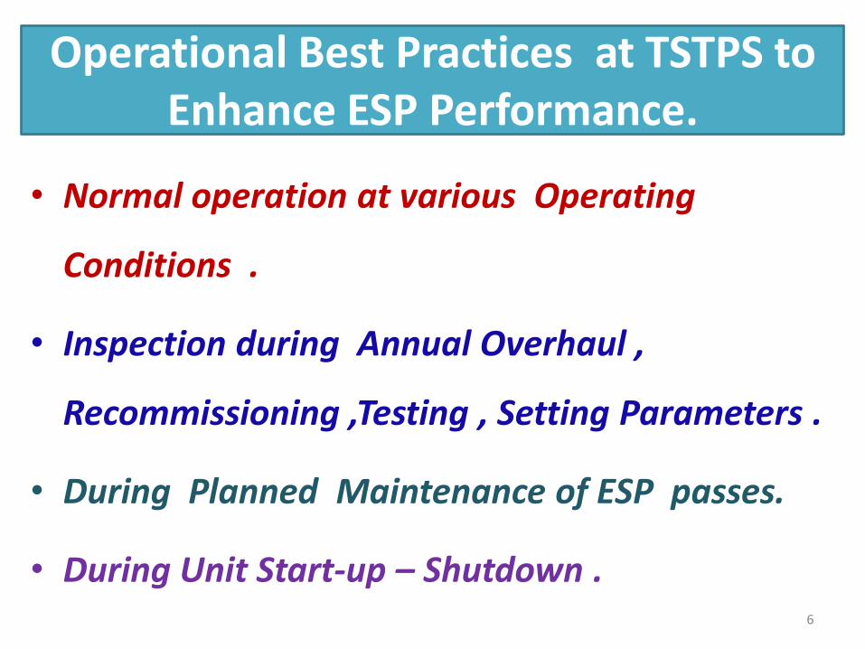
Operational Best Practices at TSTPS to Enhance ESP Performance.
• Normal operation at various Operating
Conditions .
• Inspection during Annual Overhaul ,
Recommissioning ,Testing , Setting Parameters .
• During Planned Maintenance of ESP passes.
• During Unit Start-up – Shutdown .
6

Normal Operational Strategies For ESP At Various Unit Operating Conditions .
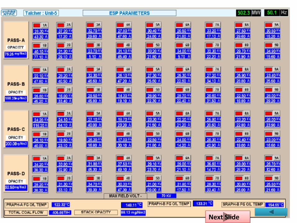
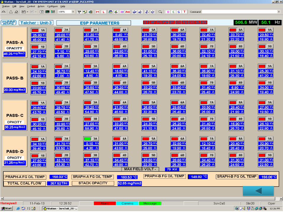
• Monitoring of ESP online Field Parameters .
• Monitoring Effective Evacuation from Eco Hoppers .
• Strategies adopted for Higher Particle Sizing at ESP Inlet due to 1st field out of service .
• Strategies for high coal flow > worst coal firing
• ESP Hopper Effective Evacuation Monitoring through PI system .
• Regular FA system checks for system performance improvement .
• Improvement of Ash Flowability from ESP Hopper .
7

Inspection During Annual Overhaul , Recommissioning .
• Checking for Uniform flue gas distribution across the entire unit by proper inspection & repair of GD screen /Baffels .
• Proper inspection & cleaning of support & shaft system .
• Proper alignment of Emitting electrodes and collecting plates .
• Proper insulation of ESP Hoppers /Casings.
• Checking Proper installation and operation of FA system devices.
• Testing’s Followed by Recommissioning of ESP & FA system
8

Testing’s Followed by Recommissioning of ESP & FA system :
• Support insulator Heater , shaft Insulator heater healthiness checking , effectiveness checking by switching ON for 24 Hrs . Subsequent current measurement .
• After total readiness , continuous rapping for 8 Hrs all GDRM/CREM/EREM , then internal inspection & hopper portion final water wash before box up .
• 24 hrs support /shaft insulator Heater in service before field meggering .
• Each ESP Field Meggering to ensure electrical healthiness . (> 250 MΩ)
• Still air charging & VI characteristic checking for all Fields to identify problems , then subsequent field internal inspection & rectification .
• Inspection of 1st hopper after Furnace pressurisation test is completed .( to remove foreign material if any)
• Air tightness test of ESP up to ESP outlet by pressurizing boiler up to 100 mmwc.
9
Next Slide

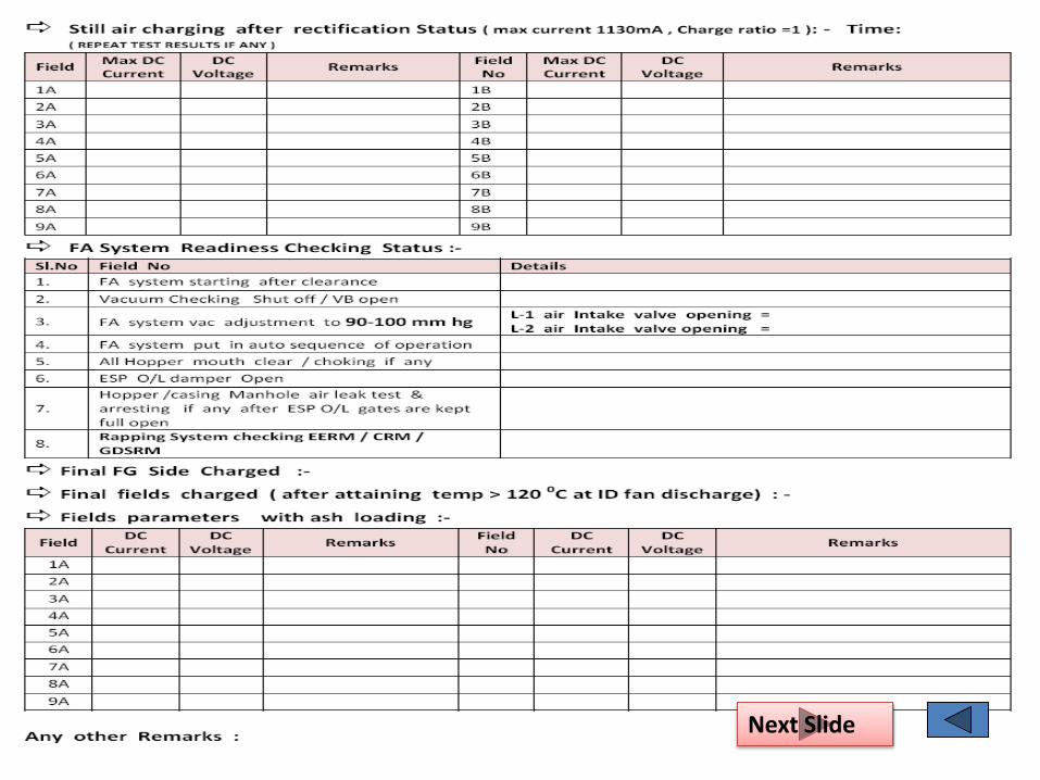
Testing’s Followed by Recommissioning of ESP & FA system :
• Hopper Heater current check ,
• Dust level LO/HI indicator operation check .
• P&I check for Rectiformers .
• Gas load testing of Fields to create data base after synchronization .
• Rapper frequency and intensity adjustment later when the unit is brought on-line.
• FA evacuation system Checks .
• Hot tightening of FA evacuation system after one day .
10 Next Slide

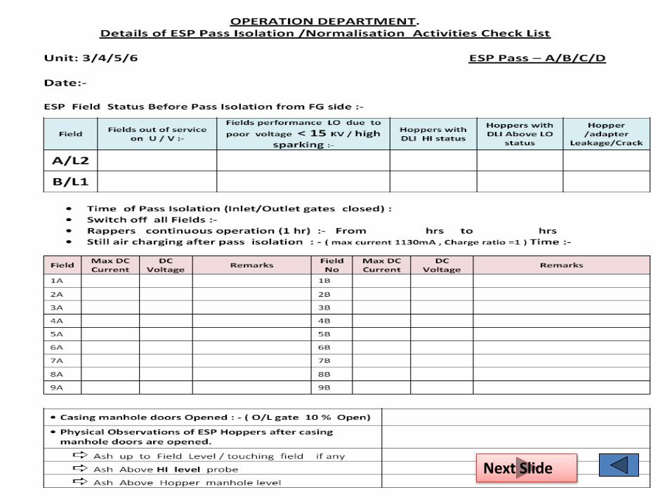
During Planned Maintenance of ESP in Operating Units . (ESP Pass isolation for Rectification).
• Whenever number of field goes out of service > 2-3 then planned maintenance of the pass is taken up .
• Effort is put not to loose generation by firing good quality coal to restrict coal flow at 370 T/hr.
• A systematic approach through a standard check list is adopted by operation engineers while ESP pass shutdown activities are carried out .
• This also guides & helps the maintenance personnel for proper & effective inspection & rectification work .
• Still air charging of fields before isolation & after rectification is carried out to ascertain problems /problems are rectified respectively
• Meggering is carried out where problems are not visibly identified .
11 Next Slide
During unit start up – shutdown .
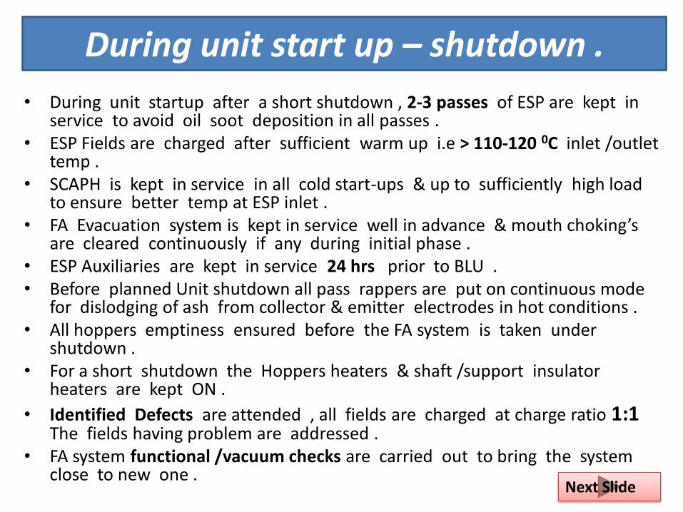
• During unit startup after a short shutdown , 2-3 passes of ESP are kept in service to avoid oil soot deposition in all passes .
• ESP Fields are charged after sufficient warm up i.e > 110-120 0C inlet /outlet temp .
• SCAPH is kept in service in all cold start-ups & up to sufficiently high load to ensure better temp at ESP inlet .
• FA Evacuation system is kept in service well in advance & mouth choking’s are cleared continuously if any during initial phase .
• ESP Auxiliaries are kept in service 24 hrs prior to BLU . • Before planned Unit shutdown all pass rappers are put on continuous mode
for dislodging of ash from collector & emitter electrodes in hot conditions . • All hoppers emptiness ensured before the FA system is taken under
shutdown . • For a short shutdown the Hoppers heaters & shaft /support insulator
heaters are kept ON .
• Identified Defects are attended , all fields are charged at charge ratio 1:1 The fields having problem are addressed .
• FA system functional /vacuum checks are carried out to bring the system close to new one .
12 Next Slide

GIST OF MAJOR MODIFICATIONS CARRIED OUT .
13
STAGE-I STAGE- II
• ESP Controllers are up graded recently
by BHEL
• ESP online parameters data provided
through DCS
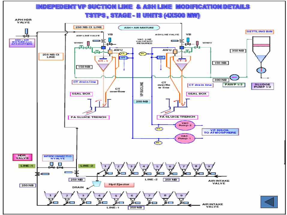
• VP suction line /ASH LINE modified
(made independent) all 6 VP can be
kept in service
• ESP OUTLET SIDE GAS SCREEN REMOVED IN
ALL FIELDS OF U 5&6 , UP TO 7TH FIELD IN U
3&4 (balance to be carried out)
• DURING R&M ASH HANDLING
SYSTEM DATA TO BE HOOKED UP
TO PI SYSTEM
• VP suction line /ASH LINE modified (made
independent) all 8 VP can be kept in
service
• BOILER HOPPER DISCONNECTION
FROM ESP SYSTEM UNDER PROGRESS
• Ash Line made independent , . Additional
water source provided from SW network .
• ESP R&M PLANNED & CONTRACT
AWRADED TO MEET THE STRINGENT
NORMS
• Major evacuation monitoring data provided
in PI system .
• ECO HOPPER EFFECTIVE EVACUATION
MONITORED THROUGH PI SYSTEM ( TE
INSTALLED )

CONCLUSION : • The role played by operation engineers in formulating
strategies /practices is very important .
• To sustain the overall ESP performance , the operation support group discusses all the strategies with shift operation group on General shift days .
• After implementation of all best practices as discussed , at TSTPS the overall performance of ESP & Ash evacuation system improved indicated by consistency in ESP field availability .
• The PI system has further strengthened in monitoring , analyzing and inturn developing the operating personnel to a larger extent in maintaining & improving ESP performance .
14

15

Checking Proper installation and operation of FA system devices .
• Vacuum Checks . • Shutoff vacuum .
• Shutoff vacuum with air lock valve close.
• Vacuum with VB open
• Line Vacuum
• Functional Checks .
• Hopper empty vacuum check .
• Valve 100 % opening check .
16
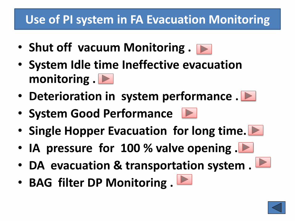
Use of PI system in FA Evacuation Monitoring
• Shut off vacuum Monitoring .
• System Idle time Ineffective evacuation monitoring .
• Deterioration in system performance .
• System Good Performance
• Single Hopper Evacuation for long time.
• IA pressure for 100 % valve opening .
• DA evacuation & transportation system .
• BAG filter DP Monitoring .
17
18 Next Slide
19
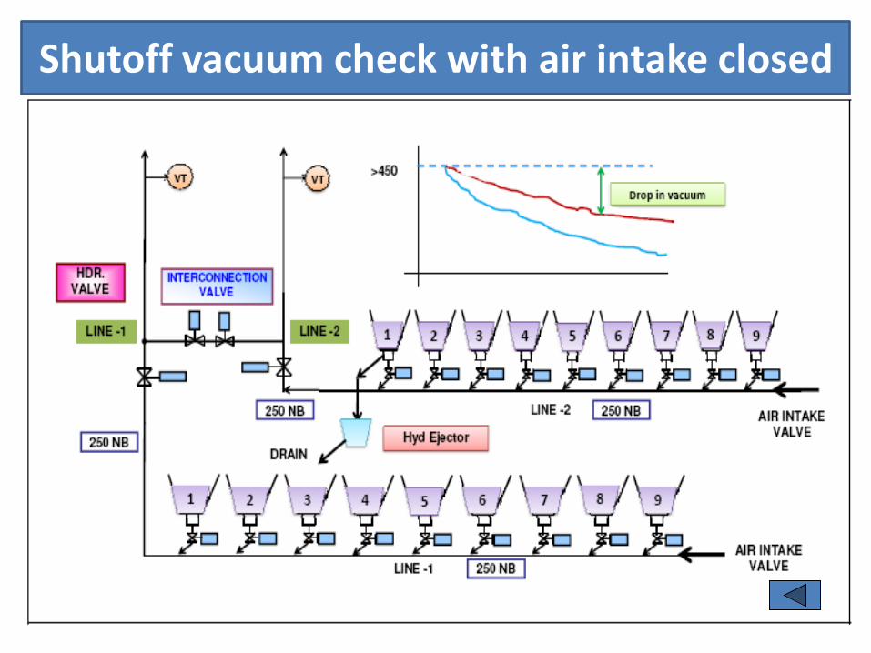
Shutoff vacuum check with air intake closed
20

Economiser Hopper Evacuation temp Trend
21
3HNA30CT101.DACA.PV
52.280
3HNA30CT102.DACA.PV
38.108
3HNA30CT103.DACA.PV
54.672
3HNA30CT104.DACA.PV
44.367
4HNA30CT101.DACA.PV
38.025
4HNA30CT102.DACA.PV
36.721
4HNA30CT103.DACA.PV
36.638
4HNA30CT104.DACA.PV
30.518
2/9/2013 12:28:31 PM2/6/2013 8:28:31 PM 2.67 days
Plot-0
0
50
100
150
200
250
300
2/7/2013 2:00:00 PM
44.510
39.297
46.099
40.973
218.84
228.75
185.21
147.98
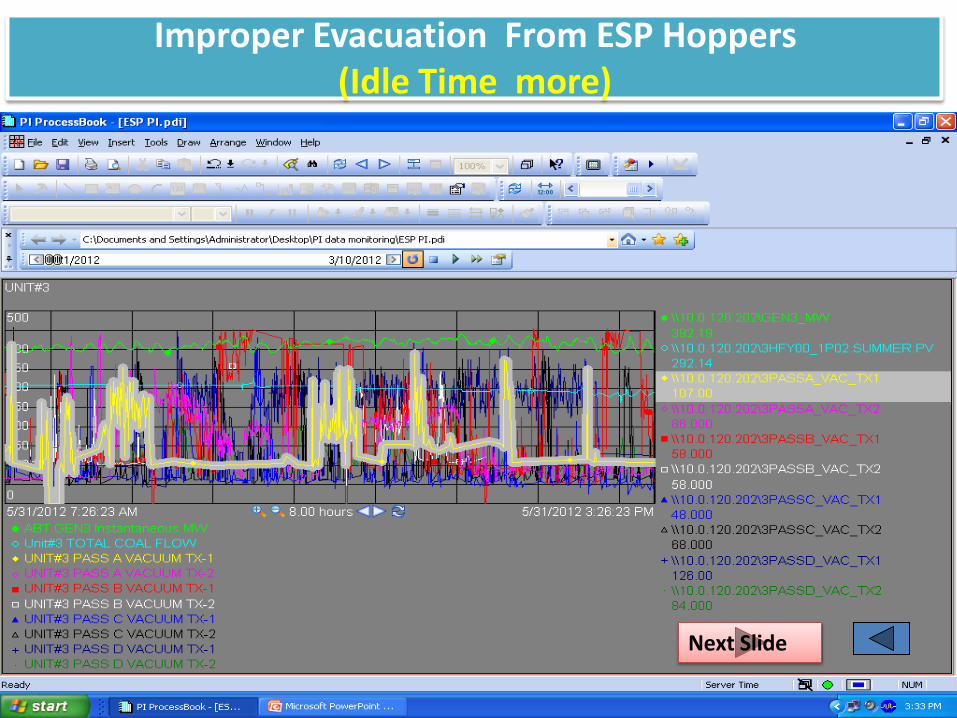
Improper Evacuation From ESP Hoppers (Idle Time more)
22
Next Slide

Improper Evacuation From ESP Hoppers
23
Next Slide

Improper Evacuation From ESP Hoppers
24
Next Slide

Improper Evacuation
25
\\10.0.120.202\GEN6_MW
356.37
\\10.0.120.202\6HFY00_1P02.SUMMER.PV
420.25
\\10.0.120.202\6PASSA_VAC_TX1
69.336
\\10.0.120.202\6PASSA_VAC_TX2
241.64
\\10.0.120.202\6PASSB_VAC_TX1
212.16
\\10.0.120.202\6PASSB_VAC_TX2
254.28
\\10.0.120.202\6PASSC_VAC_TX1
193.21
\\10.0.120.202\6PASSC_VAC_TX2
293.67
\\10.0.120.202\6PASSD_VAC_TX1
210.25
\\10.0.120.202\6PASSD_VAC_TX2
107.14
ABT.GEN6 Instantaneous MW
Unit#6 TOTAL COAL FLOW
UNIT#6 PASS A VACUUM TX-1
UNIT#6 PASS A VACUUM TX-2
UNIT#6 PASS B VACUUM TX-1
UNIT#6 PASS B VACUUM TX-2
UNIT#6 PASS C VACUUM TX-1
UNIT#6 PASS C VACUUM TX-2
UNIT#6 PASS D VACUUM TX-1
UNIT#6 PASS D VACUUM TX-2
8/24/2012 11:33:41 AM8/24/2012 9:33:41 AM 2.00 hours
UNIT#6
0
100
200
300
400
500
600
Next page

Hopper Evacuation With out proper vacuum
26
\\10.0.120.202\GEN4_MW
351.97
\\10.0.120.202\4HFY00_1P02.SUMMER.PV
281.99
\\10.0.120.202\4PASSA_VAC_TX1
191.00
\\10.0.120.202\4PASSA_VAC_TX2
74.000
\\10.0.120.202\4PASSB_VAC_TX1
180.00
\\10.0.120.202\4PASSB_VAC_TX2
277.00
\\10.0.120.202\4PASSC_VAC_TX1
279.00
\\10.0.120.202\4PASSC_VAC_TX2
210.00
\\10.0.120.202\4PASSD_VAC_TX1
0.0000
\\10.0.120.202\4PASSD_VAC_TX2
82.000
ABT.GEN4 Instantaneous MW
Unit#4 TOTAL COAL FLOW
UNIT#4 PASS A VACUUM TX-1
UNIT#4 PASS A VACUUM TX-2
UNIT#4 PASS B VACUUM TX-1
UNIT#4 PASS B VACUUM TX-2
UNIT#4 PASS C VACUUM TX-1
UNIT#4 PASS C VACUUM TX-2
UNIT#4 PASS D VACUUM TX-1
UNIT#4 PASS D VACUUM TX-2
8/29/2012 7:42:54 PM8/29/2012 5:42:54 PM 2.00 hours
UNIT#4
0
50
100
150
200
250
300
350
400
450
500

U-4 A pass Evacuation deterioration VP suction line choking
27
\\10.0.120.202\GEN4_MW
511.03
\\10.0.120.202\4HFY00_1P02.SUMMER.PV
374.15
\\10.0.120.202\4PASSA_VAC_TX1
0.0000
\\10.0.120.202\4PASSA_VAC_TX2
211.00
\\10.0.120.202\4PASSB_VAC_TX1
95.000
\\10.0.120.202\4PASSB_VAC_TX2
222.00
\\10.0.120.202\4PASSC_VAC_TX1
228.00
\\10.0.120.202\4PASSC_VAC_TX2
0.0000
\\10.0.120.202\4PASSD_VAC_TX1
68.000
\\10.0.120.202\4PASSD_VAC_TX2
60.000
ABT.GEN4 Instantaneous MW
Unit#4 TOTAL COAL FLOW
UNIT#4 PASS A VACUUM TX-1
UNIT#4 PASS A VACUUM TX-2
UNIT#4 PASS B VACUUM TX-1
UNIT#4 PASS B VACUUM TX-2
UNIT#4 PASS C VACUUM TX-1
UNIT#4 PASS C VACUUM TX-2
UNIT#4 PASS D VACUUM TX-1
UNIT#4 PASS D VACUUM TX-2
11/26/2012 9:03:46.445 AM11/25/2012 1:03:46.445 AM 1.33 days
UNIT#4
0
100
200
300
400
500
600
Indicates Empty Vacuum is increasing , suction line choking , System stopped

Dry ash transportation trend
28
\\10.0.120.202\U56_INSTAIR_HDRPR
5.0244
kg/cm2
\\10.0.120.202\U34_INSTAIR_HDRPR
5.6732
kg/cm2
\\10.0.120.202\3LINE1PRESSURE
0.57218
kg/cm2
\\10.0.120.202\3LINE2PRESSURE
0.64831
kg/cm2
Unit#5&6 ESP INST AIR HDR PRESSURE
Unit#3&4 ESP INST AIR HDR PRESSURE
Unit#3 DRY ASH TRANSPORT LINE L1 PRESSURE
Unit#3 DRY ASH TRANSPORT LINE L2 PRESSURE
11/11/2012 4:51:28 PM11/11/2012 12:51:28 AM 16.00 hours
IA & TR Line Press
0
1
2
3
4
5
5.7
Next Slide
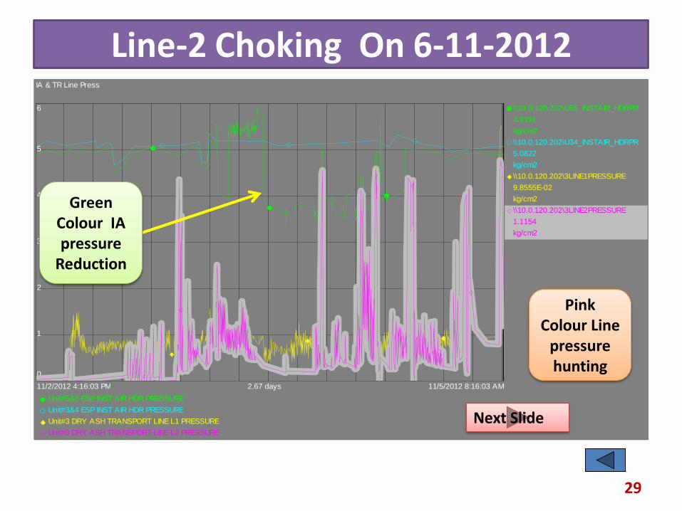
Line-2 Choking On 6-11-2012
29
\\10.0.120.202\U56_INSTAIR_HDRPR
4.9191
kg/cm2
\\10.0.120.202\U34_INSTAIR_HDRPR
5.0822
kg/cm2
\\10.0.120.202\3LINE1PRESSURE
9.8555E-02
kg/cm2
\\10.0.120.202\3LINE2PRESSURE
1.1154
kg/cm2
Unit#5&6 ESP INST AIR HDR PRESSURE
Unit#3&4 ESP INST AIR HDR PRESSURE
Unit#3 DRY ASH TRANSPORT LINE L1 PRESSURE
Unit#3 DRY ASH TRANSPORT LINE L2 PRESSURE
11/5/2012 8:16:03 AM11/2/2012 4:16:03 PM 2.67 days
IA & TR Line Press
0
1
2
3
4
5
6
Pink Colour Line
pressure hunting
Green Colour IA pressure
Reduction
Next Slide
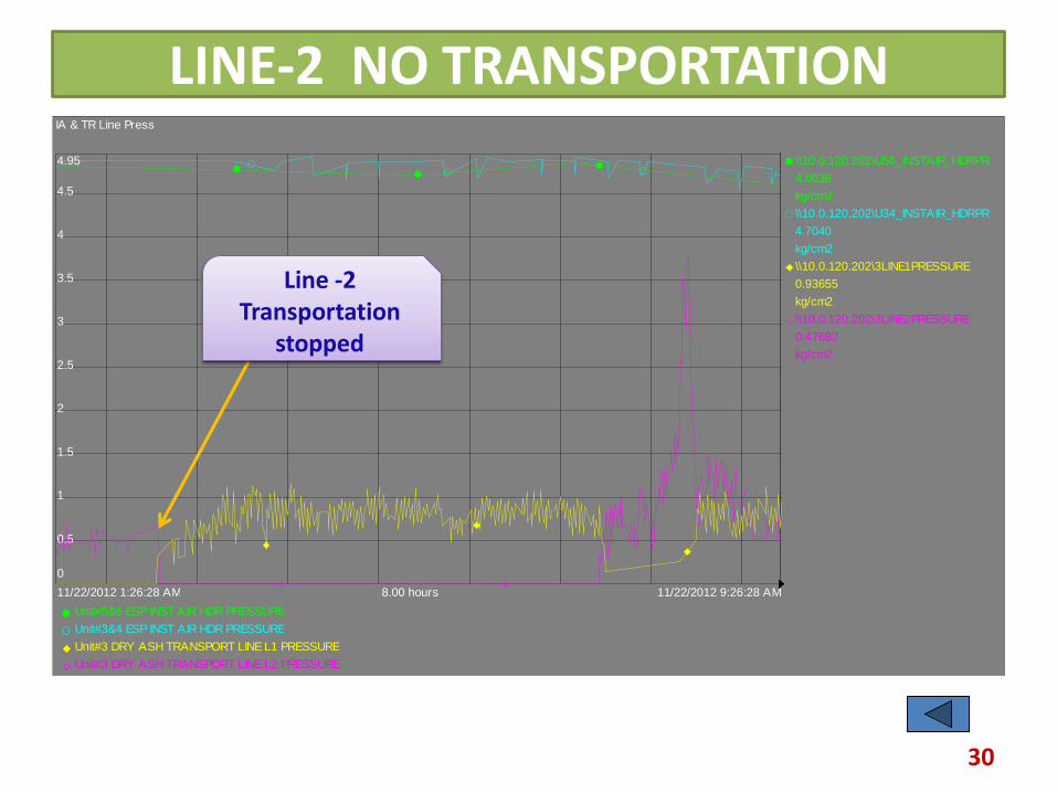
LINE-2 NO TRANSPORTATION
30
\\10.0.120.202\U56_INSTAIR_HDRPR
4.6036
kg/cm2
\\10.0.120.202\U34_INSTAIR_HDRPR
4.7040
kg/cm2
\\10.0.120.202\3LINE1PRESSURE
0.93655
kg/cm2
\\10.0.120.202\3LINE2PRESSURE
0.47682
kg/cm2
Unit#5&6 ESP INST AIR HDR PRESSURE
Unit#3&4 ESP INST AIR HDR PRESSURE
Unit#3 DRY ASH TRANSPORT LINE L1 PRESSURE
Unit#3 DRY ASH TRANSPORT LINE L2 PRESSURE
11/22/2012 9:26:28 AM11/22/2012 1:26:28 AM 8.00 hours
IA & TR Line Press
0
0.5
1
1.5
2
2.5
3
3.5
4
4.5
4.95
Line -2 Transportation
stopped
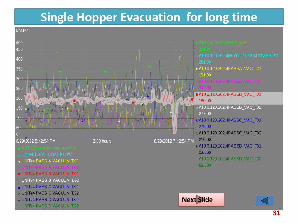
Single Hopper Evacuation for long time
31
\\10.0.120.202\GEN4_MW
351.97
\\10.0.120.202\4HFY00_1P02.SUMMER.PV
281.99
\\10.0.120.202\4PASSA_VAC_TX1
191.00
\\10.0.120.202\4PASSA_VAC_TX2
74.000
\\10.0.120.202\4PASSB_VAC_TX1
180.00
\\10.0.120.202\4PASSB_VAC_TX2
277.00
\\10.0.120.202\4PASSC_VAC_TX1
279.00
\\10.0.120.202\4PASSC_VAC_TX2
210.00
\\10.0.120.202\4PASSD_VAC_TX1
0.0000
\\10.0.120.202\4PASSD_VAC_TX2
82.000
ABT.GEN4 Instantaneous MW
Unit#4 TOTAL COAL FLOW
UNIT#4 PASS A VACUUM TX-1
UNIT#4 PASS A VACUUM TX-2
UNIT#4 PASS B VACUUM TX-1
UNIT#4 PASS B VACUUM TX-2
UNIT#4 PASS C VACUUM TX-1
UNIT#4 PASS C VACUUM TX-2
UNIT#4 PASS D VACUUM TX-1
UNIT#4 PASS D VACUUM TX-2
8/29/2012 7:42:54 PM8/29/2012 5:42:54 PM 2.00 hours
UNIT#4
0
50
100
150
200
250
300
350
400
450
500
Next Slide

Single Hopper Evacuation for long duration
32
\\10.0.120.202\GEN4_MW
351.97
\\10.0.120.202\4HFY00_1P02.SUMMER.PV
281.99
\\10.0.120.202\4PASSA_VAC_TX1
191.00
\\10.0.120.202\4PASSA_VAC_TX2
74.000
\\10.0.120.202\4PASSB_VAC_TX1
180.00
\\10.0.120.202\4PASSB_VAC_TX2
277.00
\\10.0.120.202\4PASSC_VAC_TX1
279.00
\\10.0.120.202\4PASSC_VAC_TX2
210.00
\\10.0.120.202\4PASSD_VAC_TX1
0.0000
\\10.0.120.202\4PASSD_VAC_TX2
82.000
ABT.GEN4 Instantaneous MW
Unit#4 TOTAL COAL FLOW
UNIT#4 PASS A VACUUM TX-1
UNIT#4 PASS A VACUUM TX-2
UNIT#4 PASS B VACUUM TX-1
UNIT#4 PASS B VACUUM TX-2
UNIT#4 PASS C VACUUM TX-1
UNIT#4 PASS C VACUUM TX-2
UNIT#4 PASS D VACUUM TX-1
UNIT#4 PASS D VACUUM TX-2
8/29/2012 7:42:54 PM8/29/2012 5:42:54 PM 2.00 hours
UNIT#4
0
50
100
150
200
250
300
350
400
450
500

Shut Off Vacuum Check
33
\\10.0.120.202\GEN3_MW
332.01
\\10.0.120.202\3HFY00_1P02.SUMMER.PV
375.62
\\10.0.120.202\3PASSA_VAC_TX1
57.098
\\10.0.120.202\3PASSA_VAC_TX2
80.008
\\10.0.120.202\3PASSB_VAC_TX1
100.27
\\10.0.120.202\3PASSB_VAC_TX2
68.107
\\10.0.120.202\3PASSC_VAC_TX1
78.750
\\10.0.120.202\3PASSC_VAC_TX2
60.753
\\10.0.120.202\3PASSD_VAC_TX1
88.000
\\10.0.120.202\3PASSD_VAC_TX2
0.0000
ABT.GEN3 Instantaneous MW
Unit#3 TOTAL COAL FLOW
UNIT#3 PASS A VACUUM TX-1
UNIT#3 PASS A VACUUM TX-2
UNIT#3 PASS B VACUUM TX-1
UNIT#3 PASS B VACUUM TX-2
UNIT#3 PASS C VACUUM TX-1
UNIT#3 PASS C VACUUM TX-2
UNIT#3 PASS D VACUUM TX-1
UNIT#3 PASS D VACUUM TX-2
8/25/2012 7:40:45 AM8/25/2012 7:31:50 AM 8.92 minutes
UNIT#3
0
50
100
150
200
250
300
350
400
450
Shutoff Vac < 450 mmhg
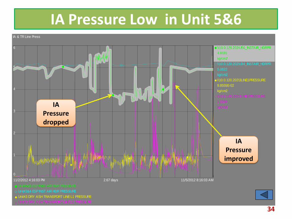
IA Pressure Low in Unit 5&6
34
\\10.0.120.202\U56_INSTAIR_HDRPR
4.9191
kg/cm2
\\10.0.120.202\U34_INSTAIR_HDRPR
5.0822
kg/cm2
\\10.0.120.202\3LINE1PRESSURE
9.8555E-02
kg/cm2
\\10.0.120.202\3LINE2PRESSURE
1.1154
kg/cm2
Unit#5&6 ESP INST AIR HDR PRESSURE
Unit#3&4 ESP INST AIR HDR PRESSURE
Unit#3 DRY ASH TRANSPORT LINE L1 PRESSURE
Unit#3 DRY ASH TRANSPORT LINE L2 PRESSURE
11/5/2012 8:16:03 AM11/2/2012 4:16:03 PM 2.67 days
IA & TR Line Press
0
1
2
3
4
5
6
IA Pressure improved
IA Pressure dropped
35 Next Slide

36 Next Slide
37 Next Slide

38

Trends of Proper FA Evacuation
39
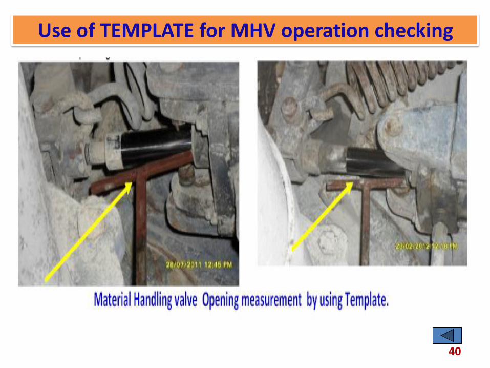
Use of TEMPLATE for MHV operation checking
40

Thermostat Location Changed
Old Thermostat Locations New thermostat locations
41
Next Slide

Hopper/Casing manhole air ingress .
HOPPER MANHOLE AIR INGRESS CASING MANHOLE AIR INGRESS
42

GD screen inspection & rectification , placement of flow baffels
43
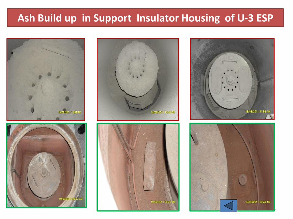
Ash Build up in Support Insulator Housing of U-3 ESP
44
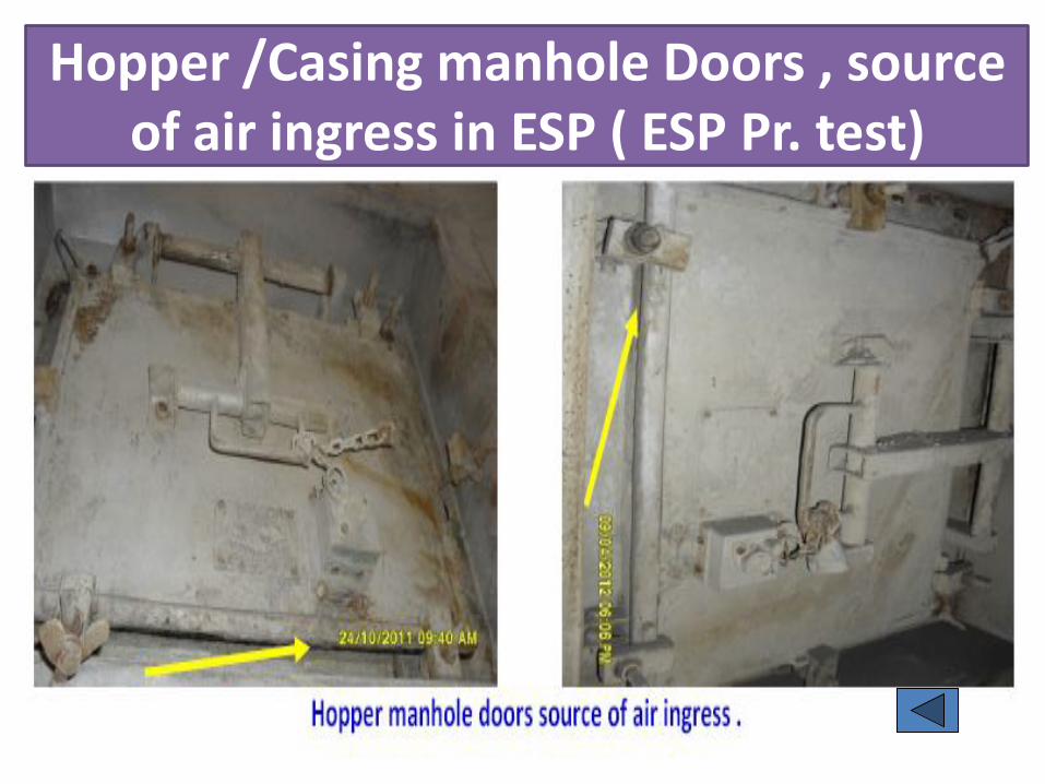
Hopper /Casing manhole Doors , source of air ingress in ESP ( ESP Pr. test)
45

ESP Field Alignment check Before & After OH
46
Next Slide

ESP Field Misalignment
47

ESP Field Non Rapping side Lower Shock bar Guide Position Check .
48

VI characteristics check for all fields
49

50
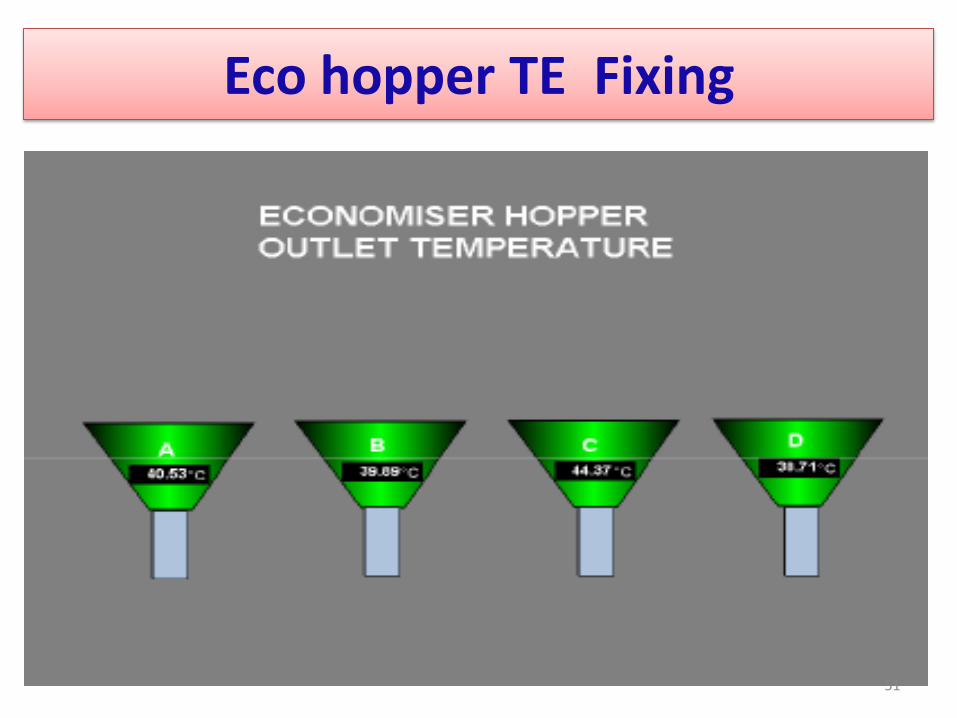
Eco hopper TE Fixing
51

52

ADVANTAGES TOWER TYPE BOILER OVER TWO PASS BOILER
53
TOWER TYPE (SINGLE PASS) INVERTED U TYPE (TWO PASS)
Heating surfaces are fully drainable (horizontal).
Restart behavior is excellent.
Heating surfaces are not drainable (vertical). Hence
slow startup and corrosion problem.
Heat exchangers are horizontal and tubes are
exposed to uniform temperature.
Heat exchangers are vertical and exposed to
different gas temperature along the height.
No blockage of ash in the convective heating
surfaces. as pitch of the coils is increasing from the
top to the bottom .
Accumulation of ash on economizer tubes where
the pitch is smaller. Hence local flue gas velocities
increases and erosion occurs.
Pressure parts wear is less due to Impact of ash by
counter action of gravity in the upward gas flow.
In rear pass the ash particles velocity accelerates
due to gravity and increases erosion.
Uniform Flue gas velocity & continuously upward
without any change in direction.
Turbulence created by the change in direction of
flue gas flow generates high local velocities causes
local erosion.
Even flow distribution of flue gas and particulates Thermal expansion of first pass and second pass is
different.
Direct load transmission to the boiler roof and free
expansion
Non-drainable heating surfaces having risk of flow
imbalance.

Spiral WW & Vertical WW Design
54
The Spiral WW Benefits from averaging of lateral
heat absorption variation (each tube forms a part of each furnace wall)
Fewer tubes than the vertical wall unit.
Simplified inlet header arrangement.
Large number of operating units. Use of smooth bore tubing
throughout entire furnace wall system. ( instead of Rifled tube)
No individual tube orifices like drum boilers .
the negative flow characteristics of the spiral furnace .
Vertical tube once through boiler Lower capital costs: Self-supporting tubes, hence
simplifying part of the boiler support system
Elimination of transition headers at spiral/vertical interface
Simpler ash hopper tubing geometry.
Lower operating costs: Lower overall boiler pressure drop,
hence lower auxiliary power load resulting in higher plant output and higher efficiency
‘Positive flow characteristic’ automatically compensates for variations in furnace absorptions .
Simple and economic tube repair Simple start-up system, a start-up
circulation pump is not required Reduced slagging of furnace walls Lower part loads down to 20% are
possible while maintaining high steam temperatures.
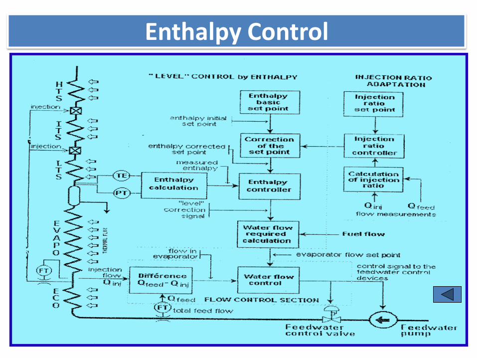
Enthalpy Control
55

Special Protections Used
56
DESCRIPTION Logic Set Value
Separator level very high and no
drainage. 2/3 > 12.9 Mtr
Evaporator flow LO-LO (FW flow - SH
spray flow) 2/3 < 420 t/hr
Spiral outlet tube metal temp. HI-HI. 3/8 470 0 C
Evaporator outlet steam temp. HI-HI 2/4 4650 C
ITSH outlet steam temp. very high. 2/4 505 0 C
LTRH outlet steam temp. very high. 2/4 520 0 C
Both the steam valves closed. 2/3 Closed

DETAILS OF UNIT STARTUP PARAMETERS. Stage - I & Stage - II Units
Parameters Stage - I Units Stage- II Units
Cold Warm Hot Cold Warm Hot
Startup Criteria
(Mean Rotor Temp ) < 160 0C
>240 0C
< 430 0C > 430 0C > 48 Hrs 0-48 hrs < 8 Hrs
BLU to Rolling
Parameters
1:20Hrs
80 min
1:15Hrs
75 min 35 min
2:05Hrs
125 min
1:25 Hrs
85 min 35 min
TG set Rolling Time i.e
up to 3000 RPM 50 min 17 min 07 min 45 min 6-7 min 6-7 min
BLU to synchronisation 2:15 hrs
135 min
1:40 min
100 min 36 min
2:50 Hrs
170 min
1:35 Hrs
95 min 50 min
Best achieved
Parameters BLU to
Synch 2:00 1:48 0:58 3:30 2:10 0:54
Synchronisation to Full
Load Operation
2:05 Hrs
125 min
1:20 Hrs
80 Min 30 Min
3:50 Hrs
230 Min
3:20 Hrs
200 Min 30 min
BLU to Full Load 4:20 hrs 3:00 Hrs 1:10 Hrs 6:40 Hrs 400 Min
5:00 Hrs
300 Min
1:20 Hrs
80 Min
57
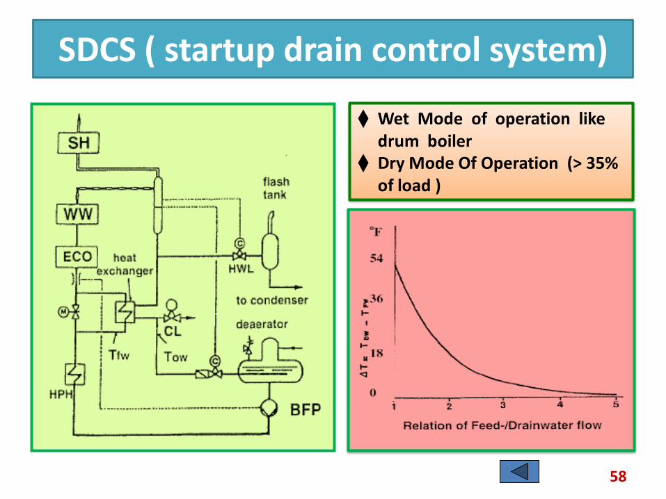
SDCS ( startup drain control system)
58
Wet Mode of operation like drum boiler
Dry Mode Of Operation (> 35% of load )

59 Next Slide

60 Next Slide

Advantages of Tube Mill
61
Advantages Disadvantages High availability Fire fighting system is additional
Low running maintenance No. Of auxiliary drives per mill are
more Constant capacity and fineness High auxiliary power consumption Hard & abrasive fuel ground
efficiency Prone for explosion
Large reserve capacity of coal Cumbersome protection &
interlocks ( Purging/steam inerting Etc)
Fast response over wide range of load
Increased fineness at low load and hence flame stability
Low air/coal ratio Wide range of coal pulverized Substantial flexibility

62 5
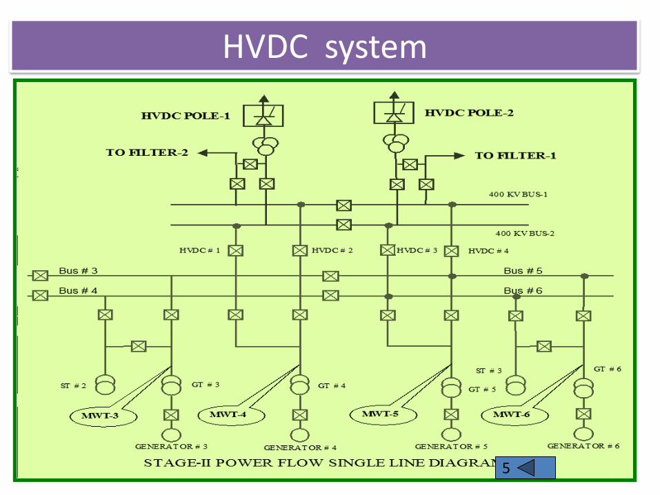
HVDC system
63 5
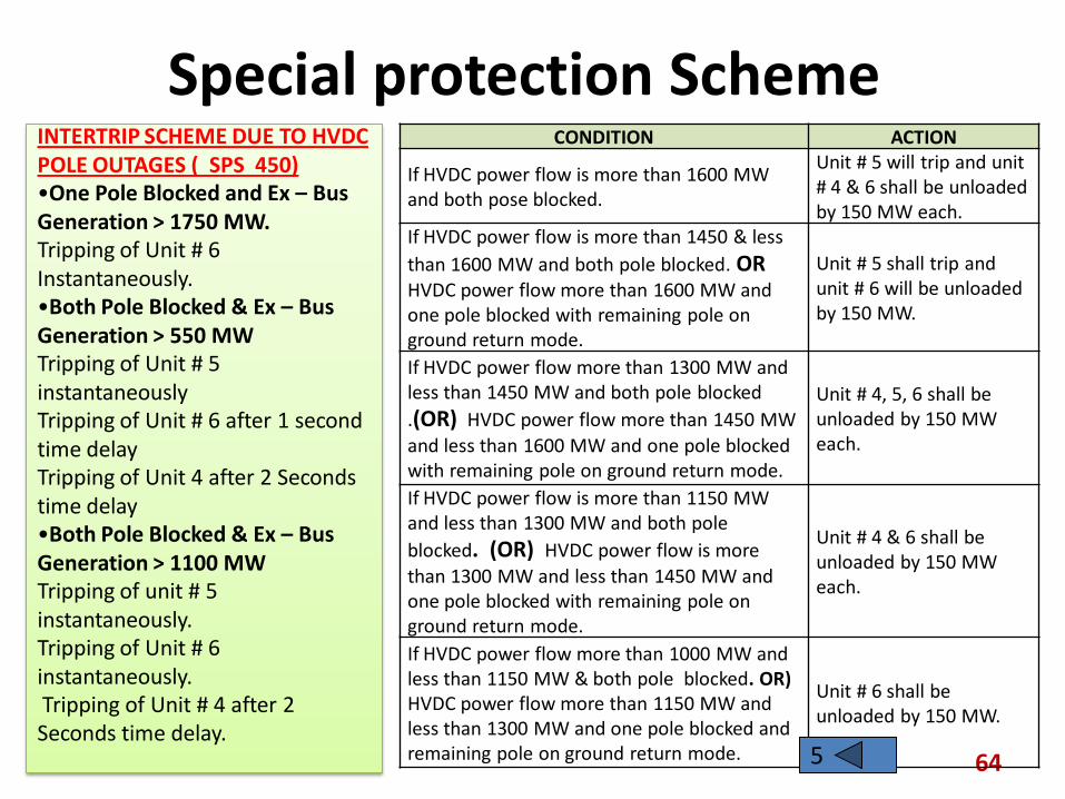
Special protection Scheme
64
CONDITION ACTION
If HVDC power flow is more than 1600 MW and both pose blocked.
Unit # 5 will trip and unit # 4 & 6 shall be unloaded by 150 MW each.
If HVDC power flow is more than 1450 & less
than 1600 MW and both pole blocked. OR HVDC power flow more than 1600 MW and one pole blocked with remaining pole on ground return mode.
Unit # 5 shall trip and unit # 6 will be unloaded by 150 MW.
If HVDC power flow more than 1300 MW and less than 1450 MW and both pole blocked
.(OR) HVDC power flow more than 1450 MW
and less than 1600 MW and one pole blocked with remaining pole on ground return mode.
Unit # 4, 5, 6 shall be unloaded by 150 MW each.
If HVDC power flow is more than 1150 MW and less than 1300 MW and both pole
blocked. (OR) HVDC power flow is more
than 1300 MW and less than 1450 MW and one pole blocked with remaining pole on ground return mode.
Unit # 4 & 6 shall be unloaded by 150 MW each.
If HVDC power flow more than 1000 MW and less than 1150 MW & both pole blocked. OR) HVDC power flow more than 1150 MW and less than 1300 MW and one pole blocked and remaining pole on ground return mode.
Unit # 6 shall be unloaded by 150 MW.
INTERTRIP SCHEME DUE TO HVDC POLE OUTAGES ( SPS 450) •One Pole Blocked and Ex – Bus Generation > 1750 MW. Tripping of Unit # 6 Instantaneously. •Both Pole Blocked & Ex – Bus Generation > 550 MW
Tripping of Unit # 5 instantaneously
Tripping of Unit # 6 after 1 second time delay
Tripping of Unit 4 after 2 Seconds time delay
•Both Pole Blocked & Ex – Bus Generation > 1100 MW
Tripping of unit # 5 instantaneously. Tripping of Unit # 6 instantaneously. Tripping of Unit # 4 after 2 Seconds time delay. 5

VFD FOR ID FANS
65
Variable frequency drive with load commutated inverter.
xmer rect
dc
inv
3-ph ac
Synch motor
EFFICIENCY OF drive systems.
Fan speed Fluid coupling VFD system
100% 85% 85%
90% 75% 84%
80% 65% 83%
70% 56% 82%
60% 46% 80%
5
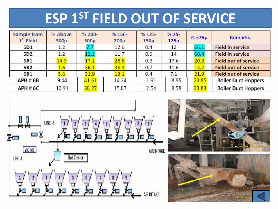
ESP 1ST FIELD OUT OF SERVICE
66

2ND LARGEST THERMAL POWER PLANT OF NTPC 67

68 NTPC KANIHA 6X500 MW UNITS
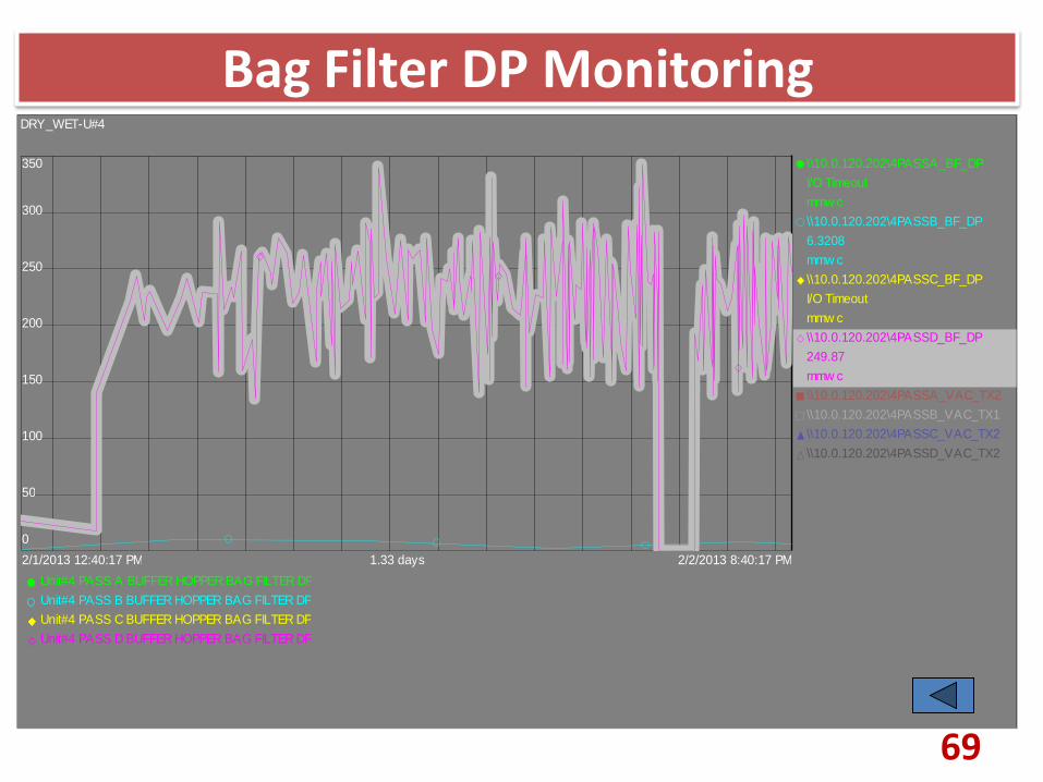
Bag Filter DP Monitoring
69
\\10.0.120.202\4PASSA_BF_DP
I/O Timeout
mmw c
\\10.0.120.202\4PASSB_BF_DP
6.3208
mmw c
\\10.0.120.202\4PASSC_BF_DP
I/O Timeout
mmw c
\\10.0.120.202\4PASSD_BF_DP
249.87
mmw c
\\10.0.120.202\4PASSA_VAC_TX2
\\10.0.120.202\4PASSB_VAC_TX1
\\10.0.120.202\4PASSC_VAC_TX2
\\10.0.120.202\4PASSD_VAC_TX2
Unit#4 PASS A BUFFER HOPPER BAG FILTER DP
Unit#4 PASS B BUFFER HOPPER BAG FILTER DP
Unit#4 PASS C BUFFER HOPPER BAG FILTER DP
Unit#4 PASS D BUFFER HOPPER BAG FILTER DP
2/2/2013 8:40:17 PM2/1/2013 12:40:17 PM 1.33 days
DRY_WET-U#4
0
50
100
150
200
250
300
350

Gas Screen Modification
70
Next Slide

Gas Screen Modification
71
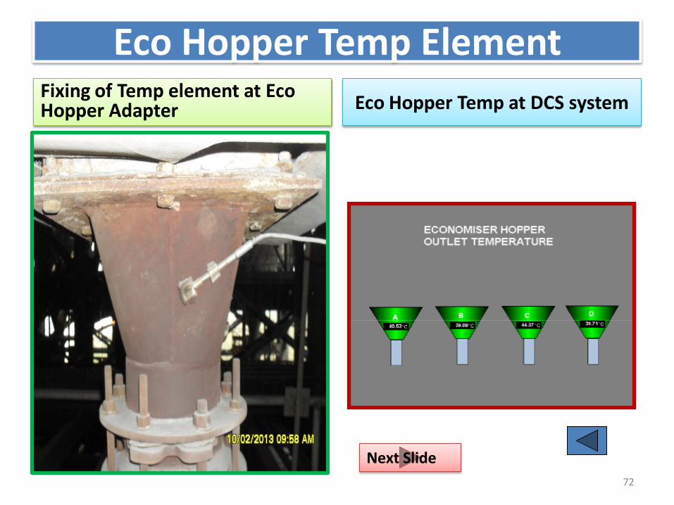
Eco Hopper Temp Element Fixing of Temp element at Eco Hopper Adapter Eco Hopper Temp at DCS system
72
Next Slide
73

74

MEGGERING OF ESP FIELD
75
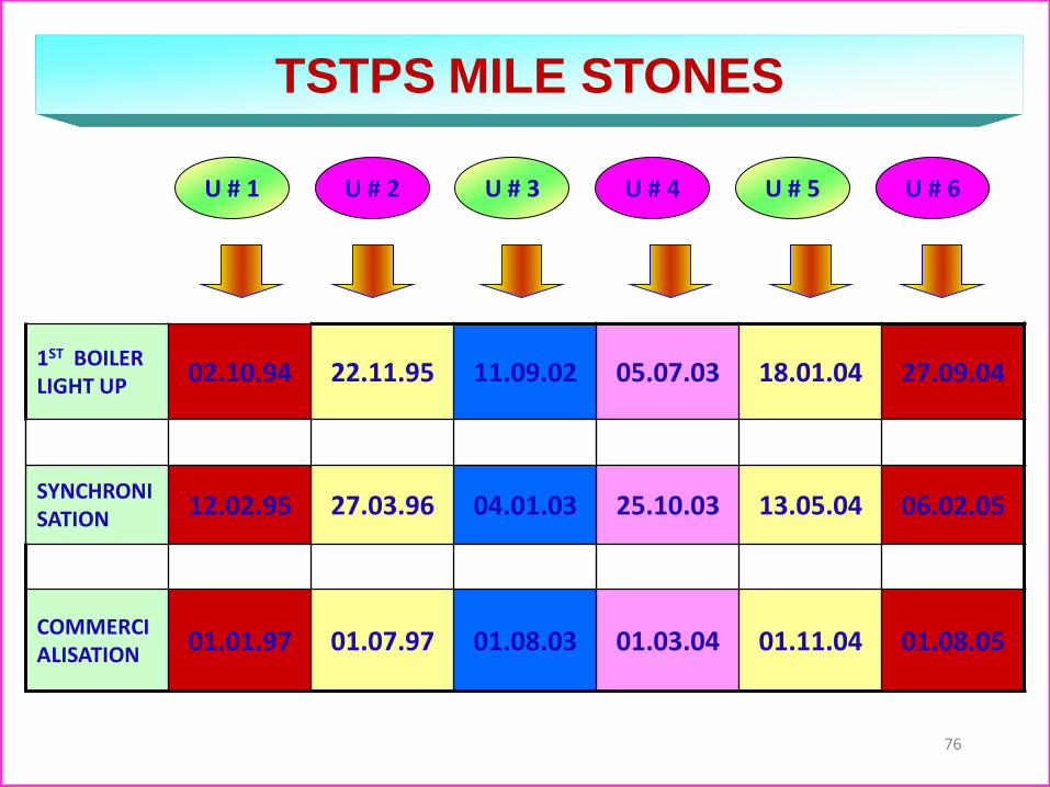
1ST BOILER LIGHT UP
02.10.94 22.11.95 11.09.02 05.07.03 18.01.04 27.09.04
SYNCHRONISATION
12.02.95 27.03.96 04.01.03 25.10.03 13.05.04 06.02.05
COMMERCIALISATION
01.01.97 01.07.97 01.08.03 01.03.04 01.11.04 01.08.05
U # 2 U # 1 U # 4 U # 6 U # 3 U # 5
TSTPS MILE STONES
76
77
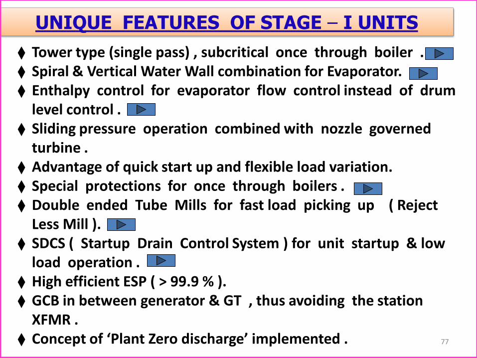
UNIQUE FEATURES OF STAGE – I UNITS
Tower type (single pass) , subcritical once through boiler . Spiral & Vertical Water Wall combination for Evaporator. Enthalpy control for evaporator flow control instead of drum
level control . Sliding pressure operation combined with nozzle governed
turbine . Advantage of quick start up and flexible load variation. Special protections for once through boilers . Double ended Tube Mills for fast load picking up ( Reject
Less Mill ). SDCS ( Startup Drain Control System ) for unit startup & low
load operation . High efficient ESP ( > 99.9 % ). GCB in between generator & GT , thus avoiding the station
XFMR . Concept of ‘Plant Zero discharge’ implemented .
78
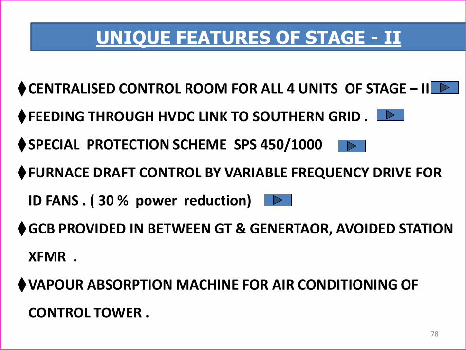
UNIQUE FEATURES OF STAGE - II
CENTRALISED CONTROL ROOM FOR ALL 4 UNITS OF STAGE – II
FEEDING THROUGH HVDC LINK TO SOUTHERN GRID .
SPECIAL PROTECTION SCHEME SPS 450/1000
FURNACE DRAFT CONTROL BY VARIABLE FREQUENCY DRIVE FOR
ID FANS . ( 30 % power reduction)
GCB PROVIDED IN BETWEEN GT & GENERTAOR, AVOIDED STATION
XFMR .
VAPOUR ABSORPTION MACHINE FOR AIR CONDITIONING OF
CONTROL TOWER .

MAJOR ESP & ASH HANDLING SYSTEM PROBLEMS EXPERIENCED AT TSTPS .
79
High FG volume loading (777 m3/sec → 1050-1100 m3/sec).
Frequent outage of 1st & 2nd fields .
Failure of Hopper Heaters .(plate type)
Failure of Gas Screens , lower shock bar guide .
Ash Flowability from ESP hoppers .
Ash Buildup in ESP Hopper , Mal Operation of ESP level
probe .
Fluidizing blower outlet temp low .
More evacuation time in B&C pass .
1st hopper evacuation in dry mode .
FA system shutdown / Back log clearing was a problem
Top Related