


Languages
Pages
Legal

Operation Modes of BJT and MOSFETCutoff, Active and Saturation
Ang Man ShunDecember 13, 2012
ReferenceSedra and Smith Microelectronic CircuitNeamen Microelectronics
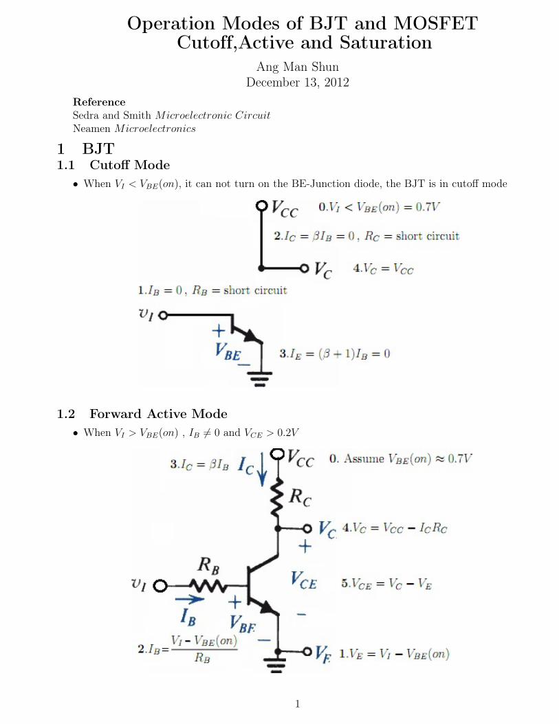
1 BJT1.1 Cutoff Mode
• When VI < VBE(on), it can not turn on the BE-Junction diode, the BJT is in cutoff mode
1.2 Forward Active Mode• When VI > VBE(on) , IB ̸= 0 and VCE > 0.2V
1
1.3 Saturation ModeRe-consider the VC again VC = VCC − ICRC
= VCC − βIBRC = VCC − βRC
(VI − VBE(on)
RB
)
=
VCC + βRC
RB
VBE(on)︸ ︷︷ ︸Constant
−
βRC
RB︸ ︷︷ ︸Constant
VI
= A−BVI
If VI increase, VC decrease
Re-consider the VCE again
VCE = VC − VE
=
VCC + βRC
RB
VBE(on)︸ ︷︷ ︸Constant
−
βRC
RB︸ ︷︷ ︸Constant
VI − [VI − VBE(on)]
=
VCC +
(βRC
RB
+ 1
)VBE(on)︸ ︷︷ ︸
Constant
−
βRC
RB
− 1︸ ︷︷ ︸Constant
VI
2
= A′ −B′VI
If VI increase, VCE decrease
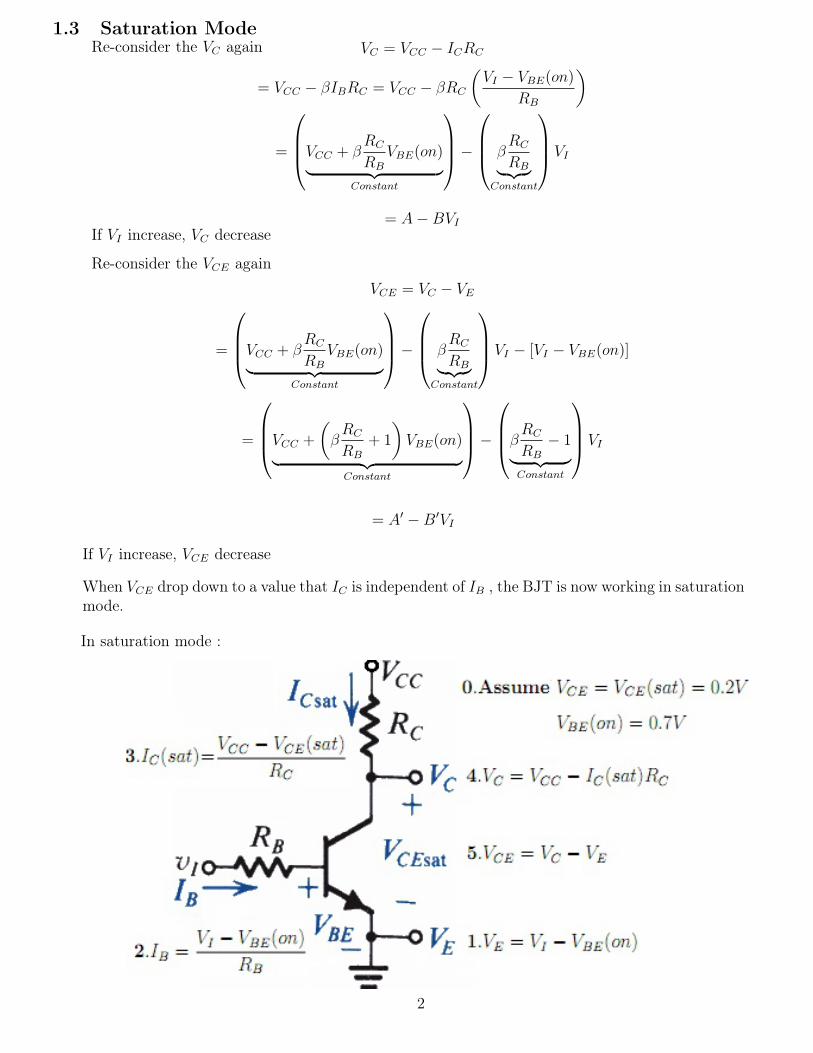
When VCE drop down to a value that IC is independent of IB , the BJT is now working in saturationmode.
In saturation mode :
VCE in this case will be smaller than VCE(sat) = 0.2V :
VCE = VC − VE
= (VCC − IC(sat)RC)− (VI − VBE(on))
= (VCC + VBE(on))− VI − IC(sat)RC
VCE = (VCC + VBE(on))− VI −VCC − VCE(sat)
RC
RC
VCE = VCE(sat)−
VI − VBE(on)︸ ︷︷ ︸>0
VI > VBE(on) , otherwise, cutoff mode ( contradiction ! ), thus VI − VBE(on) > 0 , and thus
VCE = VCE(sat)−
VI − VBE(on)︸ ︷︷ ︸>0
< VCE(sat)
VCE < VCE(sat) ≈ 0.2V
3
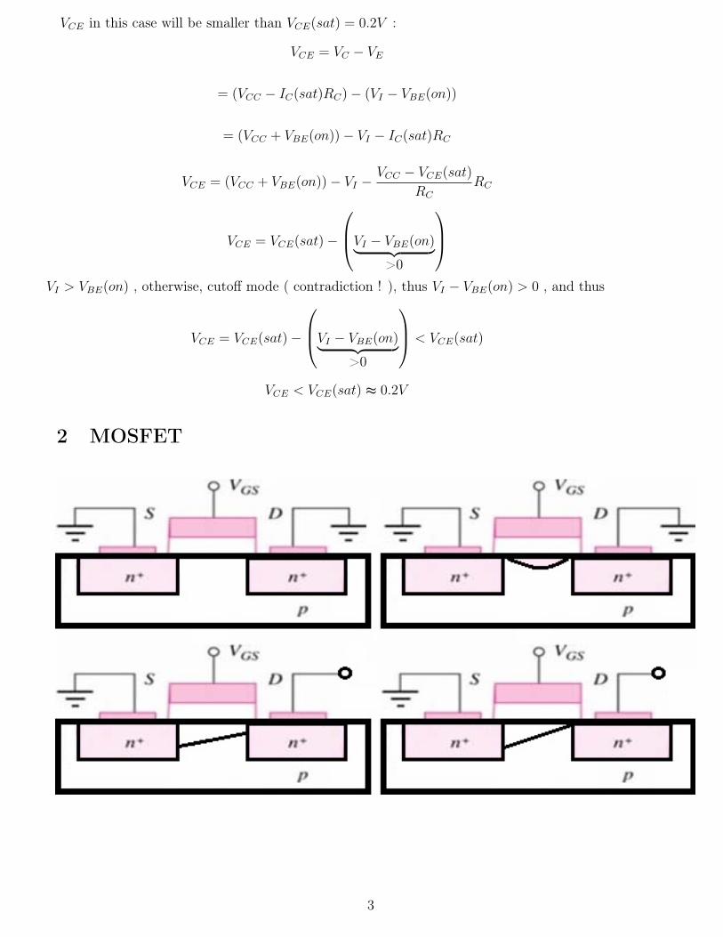
2 MOSFET
Cosider the MOS capacitor QCap = CVcap
The VCap is the excess voltage of VGS : VCap = VGS − VTN
QCap = C (VGS − VTN)
Jd = C (VGS − VTN)µnVDS
L
I = JdW = CµnW
L(VGS − VTN)VDS = kn
W
L(VGS − VTN)VDS ( In the S-side)
I = JdW = CµnW
L(VGS − VTN)VDS = kn
W
L(VGS − VTN − VDS)VDS (In the D-side)
In the middle of the device, assume linear relationship, the average current
IDS =knW
L
(VGS − VTN − VDS
2
)VDS
2.1.3 Saturation
When VDS = VGS − VTN
IDS = knW
L
(VGS − VTN − VGS − VTN
2
)(VGS − VTN) =
kn2
W
L(VGS − VTN)
2 = Kn (VGS − VTN)2
4
2.1 MOSFET Device
2.1.1 Cutoff
When VGS = 0, the MOSFET is just like two back-to-back diode, no current, so cut off.IDS = 0When VGS > 0 but VGS < VTN , since the MOSFET structure looks like a capacitor, there is somepositive charge stored in the metal plate, while in the semiconductor, there is some negative charge.Since the VGS is not large enough , so there is no “n−channel” , there is still no current.
2.1.2 Triode / Active
When VGS > VTN , there is enough voltage or E-field attraction to establish a n−channel in thesemiconductor, so the 2 n-semiconductor can now have current pass through. IDS ̸= 0
• The E-field that cause the current to drift : EDS =VDS
L
• Thus the drift velocity is vd = µnEDS = µnVDS
L
• Thus the drift current density (in A/m) is Jd = Qvd = QCapµnVDS
L
• Where the Q ( in C/m ) is the charge that drift in the n-channel, it comes from the charges storedin MOS capacitor QCap

−END−5
2.2.3 Triode / Active
2.2.2 Saturation
2.2 MOSFET Circuit Operation
2.2.1 Cutoff
Top Related