


Languages
Pages
Legal


Operation & Maintenance Manual
Tel 01992 565335Fax 01992 561562
www.clarkeinternational.comEmail [email protected]
YC6(Internal)
Super-silent Air-cooledDiesel Generator
6.0kVA 3000rpm
Clarke InternationalHemnall StreetEppingEssex CM16 4LG

YC6 (Internal)
Part Number 498-047, Issue A
E & OE.

stnetnoC
YC6 (Internal) 3
egaP stnetnoC noitceS
2.0 Specification 4 snoisnemiD lareneG 1 erugiF 1.2 5 noitacificepS lareneG 1 elbaT 2.2
3.0 Safety 7 slebaL gninraW dna snoituacerP lareneG 1.3 41 gnihtraE dna ytefaS lacirtcelE 2.3
3.3 Lifting 14 51 noitucortcelE dna htlaeH ot sdrazaH 4.3
4.0 Operation and User’s Instructions 71 eludoM lortnoC enignE 1.4
12/71 liO enignE 2.44.3 Starting 18 4.4 Stopping 18
18 snoitcennoC tuptuO rewoP 5.4 18 seciveD noitcetorP nwoD tuhS 6.4 02 lenaP lortnoC 7.4
5.0 Fault Finding 12 tratS ot sliaF enignE 1.5 22 spotS neht tub stratS enignE 2.5 22 stluaF enignE rehtO 3.5 32 tuptuO lacirtcelE oN 4.5
6.0 Maintenance 42 atobuK - eludehcS ecivreS 1.6 52 tnalooC & liO enignE 2.6 52 metsyS leuF 3.6 52 secnaraelC evlaV enignE 4.6
6.5 Battery 25 52 rotanretlA 6.6 52 )s’BCM( rekaerB tiucriC erutainiM dna tinU egakaeL htraE 7.6 52 eludoM lortnoC 8.6 52 gnigrahC yrettaB 9.6 62 yellorT dna yponaC 01.6 62 snoitcepsnI lareneG 11.6 62 gnidaoL thgiL 21.6 72 teehS droceR ecnanetniaM 31.6
7.0 Spares and Service 28 sliateD tcatnoC 1.7 28 tsiL serapS 2.7
8.0 Long Term Storage 29 egarotS mreT gnoL 1.8
9.0 Wiring Diagrams 03 gniriw CD 1.9 13 gniriw CA 2.9
23gniriWtratSetomeR3.9 33 sdaeL tratS etomeR 4.9
10.0 Notes 34 11.0 Warranty Statement 35

Section 2 Specification
4 YC6 (Internal)
2.1 Figure 1 – General Dimensions

Section 2 Specification
YC6 (Internal) 5
riA-fleW tcapmoC-repuS emaN ledoM
Basic configuration
Standard Mecc Alte version with 230V output.
Powered by Yanmar Diesel engine
For fixed / long term installation use, either in cabins or as a standby set.
Engine
Oil capacity Oil specification
Yanmar L100AE-DEG
8.8 hp / 6.5 kW 1.65 litres
15W40 API grade CG or better
Fuel
Diesel
Cooling
Forced air
Alternator
Mecc Alte SW20
Generator Power Output:
AC Power
Power factor pf
4.8kW 6.0kVA
0.8
Dimensions (approx): Height Length Width
Weight dry for shipping Weight with engine oil
and full fuel
1113mm 825mm
506mm (excluding mounting brackets) 198 kg 221 kg
Output Voltages
230V
Sockets
1 x 16A, 1x 32A BS4343
Sound Level
2006 EC Stage 2 Regulations LWA 95 dB
80db (A) @7 metres.
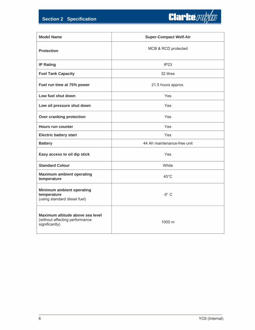
2.2 Table 1 – General Specification
Section 2 Specification
6 YC6 (Internal)
riA-fleW tcapmoC-repuS emaN ledoM
Protection MCB & RCD protected
IP Rating IP23
Fuel Tank Capacity 32 litres
Fuel run time at 75% power 21.5 hours approx.
Low fuel shut down Yes
Low oil pressure shut down Yes
Over cranking protection Yes
Hours run counter Yes
Electric battery start Yes
Battery 44 Ah maintenance-free unit
Easy access to oil dip stick Yes
Standard Colour White
Maximum ambient operating temperature 45°C
Minimum ambient operating temperature (using standard diesel fuel)
-5° C
Maximum altitude above sea level (without affecting performance significantly)
1000 m
ytefaS 3 noitceS
YC6 (Internal) 7
3.1 General Precautions
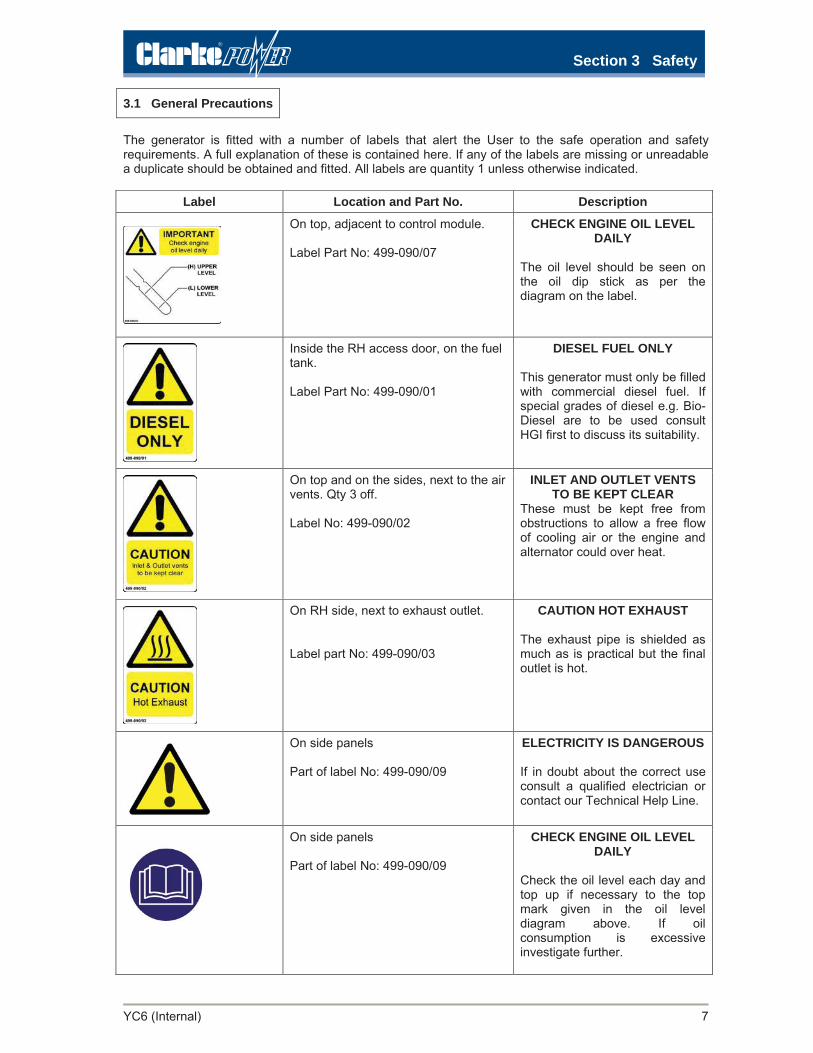
The generator is fitted with a number of labels that alert the User to the safe operation and safety requirements. A full explanation of these is contained here. If any of the labels are missing or unreadable a duplicate should be obtained and fitted. All labels are quantity 1 unless otherwise indicated.
Label Location and Part No. Description
On top, adjacent to control module. Label Part No: 499-090/07
CHECK ENGINE OIL LEVEL DAILY
The oil level should be seen on the oil dip stick as per the diagram on the label.
Inside the RH access door, on the fuel tank. Label Part No: 499-090/01
DIESEL FUEL ONLY This generator must only be filled with commercial diesel fuel. If special grades of diesel e.g. Bio-Diesel are to be used consult HGI first to discuss its suitability.
On top and on the sides, next to the air vents. Qty 3 off. Label No: 499-090/02
INLET AND OUTLET VENTS TO BE KEPT CLEAR
These must be kept free from obstructions to allow a free flow of cooling air or the engine and alternator could over heat.
On RH side, next to exhaust outlet. Label part No: 499-090/03
CAUTION HOT EXHAUST The exhaust pipe is shielded as much as is practical but the final outlet is hot.
On side panels Part of label No: 499-090/09
ELECTRICITY IS DANGEROUS If in doubt about the correct use consult a qualified electrician or contact our Technical Help Line.
On side panels Part of label No: 499-090/09
CHECK ENGINE OIL LEVEL DAILY
Check the oil level each day and top up if necessary to the top mark given in the oil level diagram above. If oil consumption is excessive investigate further.
ytefaS 3 noitceS
8 YC6 (Internal)
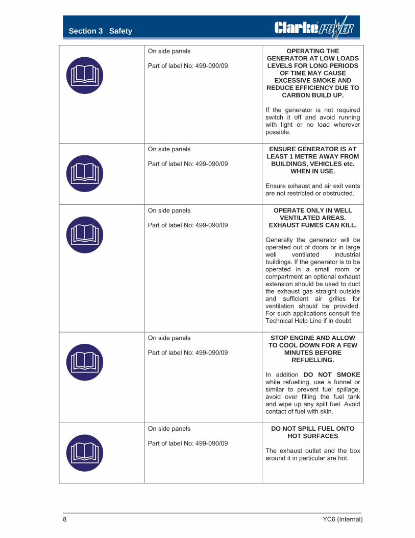
On side panels Part of label No: 499-090/09
OPERATING THE GENERATOR AT LOW LOADS LEVELS FOR LONG PERIODS
OF TIME MAY CAUSE EXCESSIVE SMOKE AND
REDUCE EFFICIENCY DUE TO CARBON BUILD UP.
If the generator is not required switch it off and avoid running with light or no load wherever possible.
On side panels Part of label No: 499-090/09
ENSURE GENERATOR IS AT LEAST 1 METRE AWAY FROM
BUILDINGS, VEHICLES etc. WHEN IN USE.
Ensure exhaust and air exit vents are not restricted or obstructed.
On side panels Part of label No: 499-090/09
OPERATE ONLY IN WELL VENTILATED AREAS.
EXHAUST FUMES CAN KILL.
Generally the generator will be operated out of doors or in large well ventilated industrial buildings. If the generator is to be operated in a small room or compartment an optional exhaust extension should be used to duct the exhaust gas straight outside and sufficient air grilles for ventilation should be provided. For such applications consult the Technical Help Line if in doubt.
On side panels Part of label No: 499-090/09
STOP ENGINE AND ALLOW TO COOL DOWN FOR A FEW
MINUTES BEFORE REFUELLING.
In addition DO NOT SMOKE while refuelling, use a funnel or similar to prevent fuel spillage, avoid over filling the fuel tank and wipe up any spilt fuel. Avoid contact of fuel with skin.
On side panels Part of label No: 499-090/09
DO NOT SPILL FUEL ONTO HOT SURFACES
The exhaust outlet and the box around it in particular are hot.

YC6 (Internal) 9
On side panels Part of label No: 499-090/09
DO NOT ADJUST THE SPEED OF THE ENGINE UNLESS YOU HAVE BEEN TRAINED TO DO
SO If the generator is not producing enough power for the application or you suspect a problem do not adjust the engine speed. This may damage the engine, alternator and any power equipment plugged into the generator.
On side panels Part of label No: 499-090/09
KEEP CHILDREN AT A SAFE DISTANCE FROM THE
EQUIPMENT AND DO NOT ALLOW THEM TO OPERATE IT This is a mandatory Health and Safety Requirement for this equipment. A version with a key switch is available if required.
On side panels Part of label No: 499-090/09
DO NOT OPERATE WITH ANY COVERS OPEN
If covers are open (or missing) the generator will exceed the European Noise Regulations and the cooling of the engine and alternator will be affected which could cause damage to them.
On side panels Part of label No: 499-090/09
ONLY OPERATE ON A LEVEL SURFACE
Generally the generator will only be used on a level surface. It can be used on small inclines but additional precautions may be needed to stop it moving due to vibration and this may also affect fuel autonomy.
ytefaS 3 noitceS

ytefaS 3 noitceS
10 YC6 (Internal)
On side panels Part of label No: 499-090/09
THIS GENERATOR SHOULD ONLY BE USED TO POWER
DOUBLE INSULATED CLASS II ELECTRICAL EQUIPMENT UNLESS THE OPTIONAL
EARTH LEAKAGE TRIP (RCD) IS FITTED.
In the UK it is currently permissible to use small mobile generators for short periods without an external earth connection being made. But ONLY double insulated electrical equipment can be powered by the generator. All modern electrical equipment intended for out doors use should be double insulated and marked with the logo.
On side panels Part of label No: 499-090/09
IF AN EARTH LEAKAGE TRIP (RCD) IS FITTED THE
GENERATOR’S BRASS EARTH STUD SHOULD BE
CONNECTED TO AN EXTERNAL EARTH FOR THE RCD TO WORK CORRECTLY. THIS EXTERNAL EARTH CAN BE AN EARTH SPIKE OR ANY SUITABLE EARTH POINT. THE
RCD SHOULD BE TESTED DAILY BY PRESSING THE
TEST BUTTON AND CHECKING IT DOES TRIP.
If the generator is to be used for a fixed installation or installed on the same site for a long period it should be installed by a competent person. The User should be shown where the TEST button is located and shown how to use it. An earth spike kit is available as an optional extra
On the front face of the base. Label part No: 499-/90/95
LWA 95 dB This is the sound level. At this level the generator should not be operated in a small space occupied by people.

YC6 (Internal) 11
On control panel. Label No: 499-090/11
EARTH POINT
If an earth leakage trip (RCD) or centre tapped to earth
alternator is fitted an M8 brass earth stud is supplied next to
the output sockets for the external earth connection.
On the main access panels. Qty 2 off. Label part No: 499-090/22
AUTOMATIC MACHINERY – MAY START WITHOUT WARNING
This is only fitted if the generator is an AMF (automatic mains failure) version intended to start the set automatically if the mains electricity fails OR a Remote Start Version.
While checking the oil level or doing any type of maintenance on this generator it should be made safe so it cannot start automatically by removing the control fuse.
On main access panels. Qty 2 off. Label part No: 499-090/15
DANGER – MOVING MACHINERY INSIDE DOOR
Moving parts will be present whilst the machine is in operation. Stop the machine and isolate before removing the door/access panel.
ytefaS 3 noitceS
ytefaS 3 noitceS
12 YC6 (Internal)
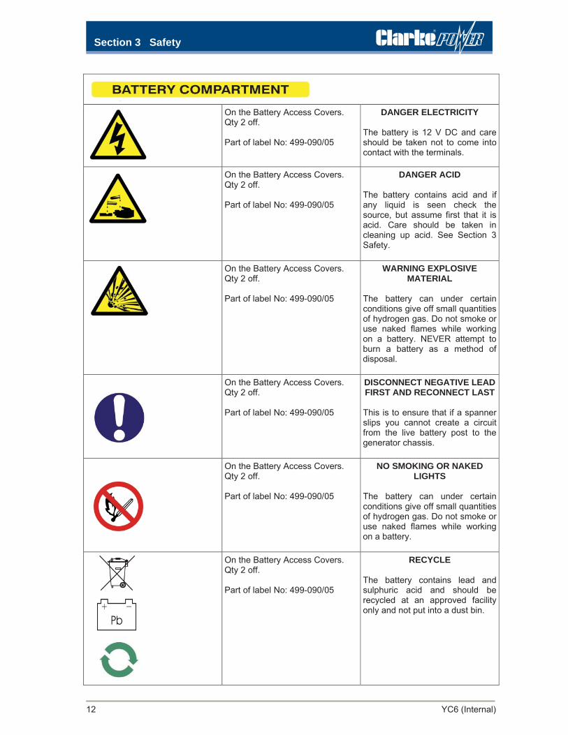
On the Battery Access Covers. Qty 2 off. Part of label No: 499-090/05
DANGER ELECTRICITY The battery is 12 V DC and care should be taken not to come into contact with the terminals.
On the Battery Access Covers. Qty 2 off. Part of label No: 499-090/05
DANGER ACID The battery contains acid and if any liquid is seen check the source, but assume first that it is acid. Care should be taken in cleaning up acid. See Section 3 Safety.
On the Battery Access Covers. Qty 2 off. Part of label No: 499-090/05
WARNING EXPLOSIVE MATERIAL
The battery can under certain conditions give off small quantities of hydrogen gas. Do not smoke or use naked flames while working on a battery. NEVER attempt to burn a battery as a method of disposal.
On the Battery Access Covers. Qty 2 off. Part of label No: 499-090/05
DISCONNECT NEGATIVE LEAD FIRST AND RECONNECT LAST This is to ensure that if a spanner slips you cannot create a circuit from the live battery post to the generator chassis.
On the Battery Access Covers. Qty 2 off. Part of label No: 499-090/05
NO SMOKING OR NAKED LIGHTS
The battery can under certain conditions give off small quantities of hydrogen gas. Do not smoke or use naked flames while working on a battery.
On the Battery Access Covers. Qty 2 off. Part of label No: 499-090/05
RECYCLE The battery contains lead and sulphuric acid and should be recycled at an approved facility only and not put into a dust bin.

YC6 (Internal) 13
On the LH Battery Access Cover Label No: 499-090/13
ENGINE OIL DRAIN
Engine oil is drained by removing the cap on the front RHS of the
base. The oil will drain easier from a warm engine. Observe correct
disposal practices.
On the RH side, above the access panel Label part No: 499-090/17
FUEL FILL THIS SIDE
The fuel filler cap is located inside this cover. Remove the cover to
access the filler and for refuelling.
DO NOT REFUEL WHILE THE SET IS RUNNING OR HOT!
On the front access panel Label part No: 499-090/16
AIR FILTER ACCESS
The Engine Air Filter is located behind this panel. Remove the panel for access to the filter for
cleaning or replacement.
On top, adjacent to the Control Module. Label No 499-090/14
LOW FUEL SHUTDOWN
The fuel gauge also incorporates a low fuel shutdown facility. The set will shut down when the level falls to approximately 10-12% of its capacity, thus eliminating the
need to bleed the system at restart.
NOTE: For generator orientation, front refers to the control panel end of the machine, thus RH and LH refer to the right and left sides when viewed from the
control panel end.
ytefaS 3 noitceS

ytefaS 3 noitceS
14 YC6 (Internal)
In addition to the information given previously the generator should be installed, earthed and used with reference to the following available from HMSO:-
I.E.E Regulations 17th Edition (BS 7671:2004)
Health and Safety Executive Publications GS27 Protection Against Electric Shock
Health and Safety Executive Publications GS24 Electricity On Construction Sites
Health and Safety Executive Publications PM53 Emergency Private Generation
Alternatively the HGI Technical Help Line would be pleased to advise on the best measures for your particular application.
This generator is NOT fully waterproof and neither the generator, nor any electrical equipment should be left out side indefinitely and operated in prolonged and heavy rain or snow. The generator is suitable to be left outside in light rain. We would NOT recommend operating hand held electrical equipment in light rain or snow.
DO NOT use a pressure washer to clean the generator as high pressure water may enter the electrical system.
In addition to the information given previously the following apply:- 3.3.1 Mechanically Assisted Lifting
The weight has been given previously in this manual but could be 221 kg with a full fuel tank. In Great Britain all assisted lifting is governed by:-
Lifting Operations & Lifting Equipment Regulations 1998 (LOLER) SI 1998 No: 2307 and the following publication should be observed:-
HSE ACoP publication L113 Safe Use of Lifting Equipment, Lifting Operations and Lifting Equipment Regulations.
As a guide line only you should ensure that all lifting equipment is:-
Sufficiently strong, stable and suitable for the proposed use. The load and anything attached must be suitable to be lifted. Positioned or installed to prevent the risk of injury, e.g. from the equipment or the load falling or
striking people. Visibly marked with any appropriate information to be taken into account for its safe use, e.g. safe
working loads. Accessories, e.g. slings, clamps etc. should be similarly marked.
You must ensure that a lifting operation must be planned, supervised and carried out in a safe manner by people who are competent. No personnel should be present in an area where a mechanical lifting operation is taking place.
3.2 Electrical Safety
3.3 Lifting and Moving

YC6 (Internal) 15
A list of the hazards that may affect health is included with safety precautions and first aid instructions.
Material / Location
serusaeM diA tsriF drazaH
Engine Oil When hot may burn the skin but not expected to give rise to an acute hazardunder normal conditions of use. May cause an allergic skin reaction in sensitive individuals. Continuous skin exposure may give rise to dermatitis. Gloves, overalls and eye protection should be worn when handling this product. Do not burn old oil as a method of disposal as combustion is likely to give rise to a complex mixture of airborne solids, liquid particulates and gases including carbon monoxide and unidentified organic and inorganic compounds. Old engine oil has potential health implications and should not come into contact with the skin. A funnel is supplied with each generator to make topping up with oil easy and clean.
Burns: Rinse with clean water, cover with a sterile pad and obtain medical assistance. Skin Contact: Remove contaminated clothing and wash thoroughly with soap and water. If persistent irritation occurs obtain medical attention. If the material is injected under high pressure into the body obtain medical assistance immediately. Inhalation: In the unlikely event of inhalation of fumes if dizziness or nausea occurs move the individual to fresh air. If symptoms persist, obtain medical attention. If difficulties are experienced with breathing a qualified person should administer oxygen. If breathing stops give artificial respiration. Eyes: In the unlikely event that the material enters the eye flush with copious quantities of clean water. If persistent irritation occurs obtain medical attention. Ingestion: In the unlikely event that ingestion occurs, wash out the mouth with water and seek medical attention. Do not induce vomiting.
Diesel Fuel May cause skin irritation. Gloves, overalls and eye protection should be worn when handling this product.
As for engine oil above.
Fibre Glass Insulation (over exhaust pipe.)
The User will not normally come into contact with this material but Service Technicians may. May cause skin and respiratory tract irritation. Gloves, overalls, dust mask and eye protection should be worn when handling this product.
Skin Contact: Remove contaminated clothing and wash thoroughly with soap and water. If persistent irritation occurs obtain medical attention. Inhalation: In the unlikely event of inhalation of dust or fibres if irritation of the mouth and throat occurs rinse with water. If persistent irritation occurs obtain medical attention. Eyes: In the unlikely event that the material enters the eye flush with copious quantities of clean water. If persistent irritation occurs obtain medical attention.
Other insulation, gaskets and seals.
No specific hazards under normal use conditions. DO NOT burn as a method of disposal as combustion is likely to give rise to a complex mixture of airborne solids, liquid particulates and gases including carbon monoxide and unidentified organic and inorganic compounds which may be hazardous to health.
n/a
Asbestos a/n .eerf sotsebsa si rotareneg sihT
3.4 Hazards to Health
ytefaS 3 noitceS

ytefaS 3 noitceS
16 YC6 (Internal)
Battery Acid Battery is located in the battery compartment at the front of the generator.
The User and Service Technicians will not normally come into contact with acid unless a battery has leaked for any reason. This is a concentrated sulphuric acid solution and may cause skin burns. Protective overalls, rubber gloves and eye protection should be worn when handling this product. If spilt dilute and wash away with copious quantities of water.
Skin Contact: Rinse skin and contaminated clothing with copious quantities of water. If persistent irritation or blistering occurs obtain medical attention. If the material is injected under high pressure into the body obtain medical assistance immediately. Inhalation: In the unlikely event of inhalation of fumes move the individual to fresh air. Obtain medical attention immediately. If difficulties are experienced with breathing a qualified person should administer oxygen. If breathing stops give artificial respiration. Eyes: In the unlikely event that the material enters the eye flush with copious quantities of clean water for at least 15 minutes. Place a sterile pad over the eye and seek medical attention immediately in all cases. Ingestion: In the unlikely event that ingestion occurs, wash out the mouth with water. Do not induce vomiting. If the patient is conscious give them water or milk to drink. Obtain medical attention immediately.
Exhaust Fumes
Exhaust fumes are very hot and contain carbon monoxide which can cause unconsciousness and death in humans and animals. It is odourless and tasteless but diesel exhaust fumes contain other chemicals and soot which will irritate the eyes and breathing and will usually alert the user to the presence of fumes. Symptoms of carbon monoxide poisoning are dizziness, nausea, fatigue and vertigo.
Skin Contact: Rinse skin with water. If persistent irritation or blistering occurs obtain medical attention Inhalation: In the event of inhalation of fumes move the individual to fresh air. If difficulties are experienced with breathing a qualified person should administer oxygen. If breathing stops give artificial respiration. Obtain medical attention in all cases. Eyes: In the unlikely event that the fumes enter the eye flush with copious quantities of clean water for at least 15 minutes. Place a sterile pad over the eye and seek medical attention immediately in all cases.
Electric Shock
Assess the situation first. DO NOT touch the person until it is safe for you to do so. Identify where the electricity is coming from. DO NOT assume it is the generator Turn off the electricity at the source. To stop generators in an emergency press the RED stop button on the generator
control panel or remove the plug from the socket. On Automatic Mains Failure Units (AMF) press the emergency stop button on the main control panel.
If necessary check patients airways, administer artificial resuscitation, move the person to the recovery position.
Even if the person remains conscious anticipate that they will pass into shock. Local burns where contact was made should be covered by a sterile dressing. Obtain medical attention immediately.
Section 4 Operating Instructions
YC6 (Internal) 17
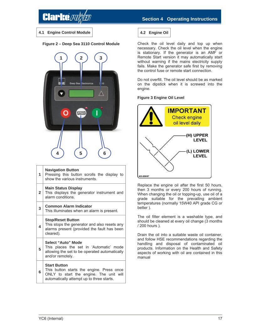
4.1 Engine Control Module
Figure 2 – Deep Sea 3110 Control Module
Check the oil level daily and top up when necessary. Check the oil level when the engine is stationary. If the generator is an AMF or Remote Start version it may automatically start without warning if the mains electricity supply fails. Make the generator safe first by removing the control fuse or remote start connection. Do not overfill. The oil level should be as marked on the dipstick when it is screwed into the engine. Figure 3 Engine Oil Level
Replace the engine oil after the first 50 hours, then 3 months or every 200 hours of running. When changing the oil or topping-up, use oil of a grade suitable for the prevailing ambient temperatures (normally 15W40 API grade CG or better ). The oil filter element is a washable type, and should be cleaned at every oil change (3 months / 200 hours ).
Drain the oil into a suitable waste oil container, and follow HSE recommendations regarding the handling and disposal of contaminated oil products. Information on the Health and Safety aspects of working with oil are contained in this manual
4.2 Engine Oil
1Navigation Button Pressing this button scrolls the display to show the various instruments.
2Main Status Display This displays the generator instrument and alarm conditions.
3 Common Alarm Indicator This illuminates when an alarm is present.
4Stop/Reset Button This stops the generator and also resets any alarms present (provided the fault has been cleared).
5Select “Auto” Mode This places the set in ‘Automatic’ mode allowing the set to be operated automatically and/or remotely.
6Start Button This button starts the engine. Press once ONLY to start the engine. The unit will automatically attempt up to three starts.
1 2 3
4 5 6

Section 4 Operating Instructions
18 YC6 (Internal)
Check the lubricating oil level and fuel level, and top up as necessary. Do not overfill. The Oil level should be as marked on the dipstick when it is screwed into the engine.
Press the Red Stop/Reset pushbutton once then press the Green Run/Start pushbutton once only and the starter motor will turn and the engine will crank.
If the engine fails to start during cranking, the Control Module will automatically attempt up to 3 starts before going to a Fail to Start alarm. Press the Red Stop push button to clear the alarm.
If the engine does not start after three attempts investigate the cause.
For Manual Starts allow the engine to warm up for 1 minute before connecting any load to the generator output. If the unit is fitted with the CN222 Remote Start/Stop control (Fig 4c), use the corresponding buttons on the remote unit.
For a Remote Start press the ‘Auto’ button. The LCD display will show confirmation of the selected mode. Upon receipt of the remote start signal the Control Module will attempt to start 3 times as above.
4.4 Stopping Manually and Remotely
For a Manual STOP, switch off the electrical output and disconnect the load. Allow the generator to run off-load for 2 minutes to cool down. Press the red Stop/Reset push button to stop the generator.
For a Remote STOP the engine note will change as the load is transferred back to the mains or removed and the set will stop unless timers have been set in which case the set will run for a pre-set time to allow for cooling.
In an emergency the red/yellow Emergency Stop button should be used. Twist and pull the button to reset it.
4.5 Power output Connections
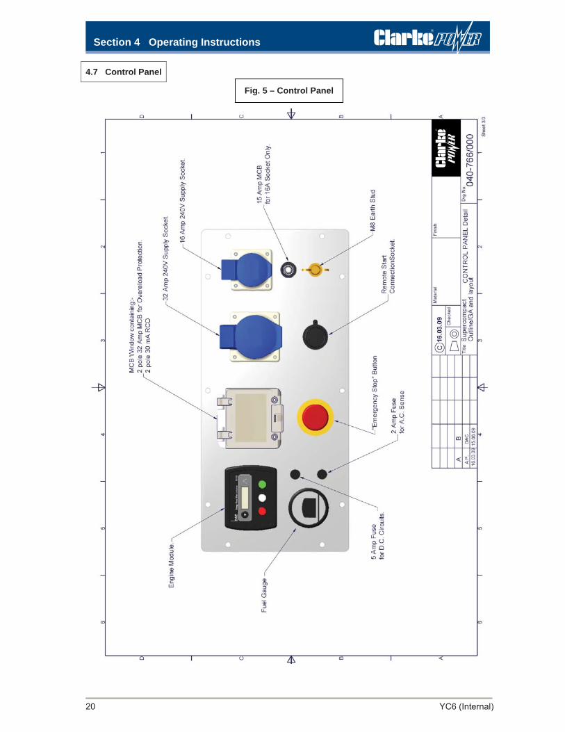
These generators will be supplied with output sockets as shown in Figure 5.
On models with an RCD (earth leakage device), the M8 brass stud next to the output sockets should be connected to an external earth point or to an earth spike. An earth spike can be supplied as an optional extra and should be driven at least 600 mm into soil.
The RCD should be tested by pressing the TEST button and checking that the RCD trips and has to be reset while the generator is running. This should be done every day. Connect the equipment to be powered (load) into the socket outlets on the generator control panel.
Operating the generator at low load levels for long periods of time may cause excessive smoking, reduce efficiency due to carbon build-up and cause other engine problems
Do not overload the generator as this will cause overheating, and shorten the life of the generator. Check that the total load from all equipment connected does not exceed the generator rating. The overall output is protected by a 32A circuit breaker while the 16A socket is also protected by an individual MCB. If the current being drawn through the socket exceeds this for a short time the MCB will trip. To reset the MCB when it has tripped remove the load, wait a few minutes and then reset. Operating the generator at low load levels for long periods of time may cause excessive smoking, reduce efficiency due to carbon build-up and cause other engine problems.
4.6 Shutdown Protection Devices
The generator is fitted with the following protection devices that will shut down the generator in the event of a fault. They are indicated on the engine control module (Fig 2):
Fail to Start. Operates if the engine fails to start after 3 attempts. This is to help prevent damage to the starter motor. If the engine fails to start then the cause should be investigated before further attempts are made.
Low Oil Pressure. This operates if the oil pressure falls below a safe level. This can be caused by a lack of oil, wrong type of oil or high temperature. Check and top up the oil level as necessary. During starting, the alarm is held off for 10 seconds to allow the oil pressure to build up to normal running level. The engine will not crank if there is no low oil pressure signal prior to starting.
Low Fuel Level. The set will shut down when the fuel level falls to approximately 10-12% of its capacity, thus eliminating the need to bleed the system at restart. In this condition, a lamp will light on the gauge (Fig 4a) and the Control Module will show a Common Alarm.
4.3 Starting Manually and Remotely

Section 4 Operating Instructions
YC6 (Internal) 19
Figure 4a – Fuel Gauge Figure 4b – Engine Compartment(view from Control Panel right)
NOTE: For safety reasons, the battery negative lead will be disconnected prior to delivery. It is recommended that this action is repeated when moving the
generator or for long term storage.
A: Contents Scale B: Low Fuel Alert C: Oil Dipstick
Figure 4c CN222 Remote Start/Stop Unit.
A B
C
Section 4 Operating Instructions
20 YC6 (Internal)
Fig. 5 – Control Panel
4.7 Control Panel

Section 5 Fault Finding
YC6 (Internal) 21
5.1 Engine Fails to Start
IMPORTANT: If the following checks and investigations can be completed without the use of tools then the User can safely undertake them. If tools are needed then ONLY trained technicians can undertake the work safely. Wiring diagrams are contained in this manual to help with electrical fault finding.
Further advice on fault-finding can be found in the Deep Sea 3000 Series Operating Manual, p.35.
ydemeR dna esuaC motpmyS
Starter motor did not attempt to turn the engine over. No display on the Control Module (Fig 2).
Check the control fuse or MCB has not failed/tripped. Flat battery or wrong polarity from battery. Check that the battery is producing over 12V DC from the positive terminal relative to the chassis of the generator. Check the connections to the control module.
Starter motor did not attempt to turn the engine over. Module display shows Fail to Start.
Check the Emergency Stop button has not been used. The control module pulls in a slave relay to put 12V DC onto the starter motor solenoid. Check the control module is not faulty by swapping it. Check it is attempting to pull in the slave relay. Check the operation of the slave relay. Check the connections to the starter motor. Check the operation of the starter motor by making a temporary connection to its solenoid.
Starter motor did not attempt to turn the engine over. Module display shows Oil pressure fault
The control module believes that oil pressure is present when the engine is off. Check the oil pressure switch has not gone faulty. Check the control module has not gone faulty by swapping it. Check the fuel level in the tank.
Engine turns over but will not start. (display shows Fail to Start after 3 attempts) No smoke seen from exhaust pipe.
Check that the fuel filter is not blocked or full of water.Check there is a 12V DC supply to the fuel solenoid valve. *Check fuel is getting past the fuel solenoid valve. *Check fuel is flowing at high pressure out of the fuel pump located next to the fuel solenoid. Suspect the fuel system is air locked or there is contamination blocking the fuel system or injector.
Engine turns over but will not start. (display shows Fail to Start after 3 attempts). Smoke seen from exhaust pipe.
Suspect faulty fuel supply as above. Suspect faulty fuel injector nozzle. Suspect contaminated / unsuitable fuel. Suspect starter motor is not turning engine over quickly enough particularly if the temperature is too low. Suspect serious fault with the engine.
* Care should be taken while working on the fuel system particularly when fuel is under high pressure.

Section 5 Fault Finding
22 YC6 (Internal)
Engine starts but then shuts down. No display on the Control Module.
Check control circuit fuses and MCB. Check the 12V DC supply from the battery has not been lost. Suspect faulty control module. Swap it to check it.
Engine starts but then shuts down. Display is lit on the Control Module.
Low Oil lit: Check the oil level. Check the oil pressure switch and wiring. Check the oil pressure. High Engine Temperature lit: Check the engine temperature. Check the HET switch and wiring. Check the fuel system has not become contaminated or defective as given previously.
Engine starts but then shuts down on Speed Fault on the Control Module.
Speed Fault - If the engine does not run within the required speed range it will shut down. The most common cause of incorrect speed is air or contamination in the fuel system. Check the fuel and filter condition, bleed the system and try starting again. Also see 5.3 below.
5.3 Other Engine faults
Engine runs but makes excessive smoke and/or runs erratically.
Check for contaminated fuel. Check for contamination in the fuel system particularly the fuel injector nozzle. Check for blocked fuel filter or water in the filter. Check for faulty or worn fuel injector nozzle. Check for blocked air filter. Suspect serious engine fault with governor, timing or compression.
Battery goes flat or will not turn over the starter motor fast enough.
Check the fuse in the battery charging circuit has not failed. Check charging system is delivering above 13V DC to the battery. The battery must be fitted to see this. If the unit is fitted with a refillable battery, check electrolyte level in the battery. This can be topped up with distilled water. If an external mains powered battery charger is fitted inside an AMF Panel check its operation.
5.2 Engine Starts but then Stops
YC6 (Internal) 23
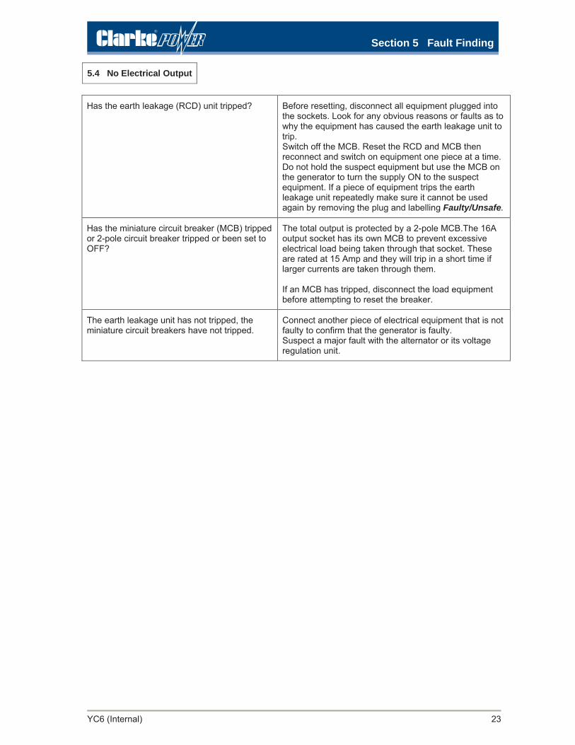
Has the earth leakage (RCD) unit tripped? Before resetting, disconnect all equipment plugged into the sockets. Look for any obvious reasons or faults as to why the equipment has caused the earth leakage unit to trip. Switch off the MCB. Reset the RCD and MCB then reconnect and switch on equipment one piece at a time. Do not hold the suspect equipment but use the MCB on the generator to turn the supply ON to the suspect equipment. If a piece of equipment trips the earth leakage unit repeatedly make sure it cannot be used again by removing the plug and labelling Faulty/Unsafe.
Has the miniature circuit breaker (MCB) trippedor 2-pole circuit breaker tripped or been set to OFF?
The total output is protected by a 2-pole MCB.The 16Aoutput socket has its own MCB to prevent excessive electrical load being taken through that socket. These are rated at 15 Amp and they will trip in a short time if larger currents are taken through them. If an MCB has tripped, disconnect the load equipment before attempting to reset the breaker.
The earth leakage unit has not tripped, the miniature circuit breakers have not tripped.
Connect another piece of electrical equipment that is not faulty to confirm that the generator is faulty. Suspect a major fault with the alternator or its voltage regulation unit.
5.4 No Electrical Output
Section 5 Fault Finding

ecivreS 6 noitceS
24 YC6 (Internal)
6.1 Service Schedule Service intervals will have to be reduced if the generator is operated in dusty or severe conditions. The first service is required after 50 hours from new then as given below. The Yanmar engine manual contains additional checks on the fuel injection system but these are only required for California. Servicing must be carried out by a competent engineer. A written record of the service work should be made using the form contained in this manual or a similar form. The generator must be serviced in accordance with our recommendations for the warranty to be valid. DO NOT use a pressure washer to clean the generator as high pressure water may enter the electrical system. Use a damp cloth or similar.
Maintenance Schedule Daily Checks
After the first 50 hours
Every 3 months or 200 hours
Every 6 months or 400 hours
Check & replenish fuel
Check & replenish engine oil
Check fuel filter for dirt and water
Check battery fluid level
Check for oil and fuel leaks
Check operation of earth leakage unit ( RCD ) trip if fitted.
Check the hours run meter works
lio enigne egnahC
retlif lio naelC
retlif leuf ecalpeR
naelc retlif ria kcehC
retlif ria ecalpeR
secnaraelc evlav tsujdA
Check alternator brushes & slip rings
s’BCM fo noitarepo kcehC
Control Module Safety Shut Down
regrahC yrettaB
yellorT dna yponaC
snoitcepsnI lareneG
Run on ¼, ½, ¾ full load for 30 minutes

ecivreS 6 noitceS
YC6 (Internal) 25
6.2 Engine Oil Check the oil level daily and top up if necessary with the funnel supplied to make this clean and easy. Check the oil level when the engine is stationary and on a level surface. Do not overfill. The oil level should be as marked on the dipstick when it is NOT screwed into the engine. Replace the oil every 3 months or 200 hours running. When changing the oil or topping-up, use oil of grade suitable for the prevailing ambient temperatures (15W40 API grade CG). The oil filter element is a washable type, and should be cleaned at every oil change (3 months / 200 hours). Drain the oil into a suitable waste oil container, and follow HSE recommendations regarding the handling and disposal of contaminated oil products
6.3 Fuel Check daily and replace the fuel filter every 6 months or 400 hours. Clean the fuel strainer located in the fuel filling neck of the fuel tank with clean fuel. Drain and flush the fuel tank periodically toprevent the build-up of contaminants, particularly when the generator has operated in high humidity and dusty environments.
6.4 Valve Clearances Valve Clearances should be checked after the first 6 months or 400hrs. The clearance for both the intake and exhaust valves should be 0.15mm when the engine is cold. Refit the rocker cover with a new gasket
6.5 Battery Check the level of the battery electrolyte every day. This should be 30 to 35 mm from the top surface of the battery and covering the plates. The battery is a maintenance free unit and should not require topping up. Check that the positive and negative terminals are tight and secure, and free from corrosion. Lightly coat them with petroleum jelly or similar to protect against corrosion. Check that the battery securing strap is tight and the battery is held firmly.
6.6 Alternator Ensure that the cooling air vents do not become blocked by dirt, debris etc
6.7 Earth Leakage Unit and MCB’s The earth leakage unit has a self test button which can be used to apply a fault and to check that the unit trips out when the generator is running. To test the MCB’s is not practical in normal circumstances.
6.8 Control Module Safety Shutdowns The module will prevent the generator from starting or shut it down if faults occur. Check the following:- Hours Run Counter: Confirm counter is working. Over cranking: Remove the 12V DC supply to the starter motor solenoid and attempt to crank for more than 10 seconds. After 10 seconds the Control Module should stop the cranking and show an alarm.
Low Oil Pressure: With the engine off, remove the connection to the normally closed oil pressure switch and attempt to start the engine. The Control Module should see an open circuit representing oil pressure when there should be none and prevent starting.
6.9 Battery Charging Stop and start the engine a few times if needed to draw off the battery. Start the engine, allow to run for 5 minutes and check that the battery charger is delivering at least 13.2V DC into the battery

ecivreS 6 noitceS
26 YC6 (Internal)
Check security of fixings and fasteners on the machine. Lubricate hinges and latches with light machine oil. Ensure that the inlet and outlet louvers are kept clean and unimpeded at all times. Check that no sound insulation has become loose and obstructed them. The engine should be sucking in air from out side the canopy. With the front panel removed, check the foam seal is complete all around this compartment and air can only be drawn from outside the set
6.11 General Inspections Inspect generally for:- Fuel and Oil Leaks: Look for excessive oil in the base tray. Look for weeps from fuel hoses and connections. Check the insulation is dry and not contaminated with fuel or oil. Worn or Failed Anti Vibration Mounts: When the side panels are removed rock the engine and check all four anti vibration mounts are flexing slightly and have not failed or broken up. Damaged or missing insulation and seals: Generally look at the sound insulation and seals and check it is still securely fitted and has not deteriorated. Missing Safety Labels: These labels are a mandatory safety requirement and if any are missing or not easy to read they should be replaced. Full details of all labels are contained in this manual. A replacement label kit is available. Chafing or Stretching of Cables: Inspect all cables and connections and look for obvious signs of wear or damage. Signs of Over Heating: Look for obvious deterioration due to heat and investigate the cause and rectify as necessary. Fuel Cap: Check the cap seals correctly. Check for obvious signs of fuel spillage.
6.12 Light Loading Operating the generator at low load levels for extended periods can result in high levels ofcarbon build up in the engine and exhaust system which can lead to excessive smoking, reduced efficiency and over heating. Looking at the silencer’s outlet will give some indication is this has happened.
After each service the generator should be run first on ¼, then ½, then ¾ and finally full load using a load bank or a similar load like an electric fan heater, to burn out any deposits of soot in the engine and silencer. Each level of load should be applied for at least 10 minutes or until the exhaust is clear of soot and smoke. If you suspect the engine is badly sooted, DO NOT apply full load but build the load up gradually. It should be anticipated that hot soot may be expelled from the exhaust during this procedure and it should be done in a safe place away from combustible material and under supervision at all times.
6.10 Canopy

ecivreS 6 noitceS
YC6 (Internal) 27
6.13 Maintenance Record Sheet
GENERATOR MAINTENANCE RECORD SHEET ( for use by owner / service agent )
Name of owner: Address:
Order No:
Name of service organisation: Address:
Job No:
Date of service:
Hours run meter reading: hrs
Service Daily / 50hrs / 3 months 200hrs / 6 months 400hrs
GENERATOR DETAILS ( From Data Plate ) Model: SUPER-COMPACT WELF-AIR Serial No: Code: Year of Manufacture: Rated Power: Power Factor PF: Voltage (Current): Fuel type:
General Condition:
Daily Checks: 1 Fuel level checked Yes/No 2 Oil level checked Yes/No 3 Battery liquid level 30/35 mm from top Yes/No 4 Check for oil / fuel leaks Yes/No 5 Check RCD works( if fitted ) Yes/No 6 Check fuel filter not contaminated Yes/No
After first 50 hours from new. Every 3 Months or 200 hrs Service
1 Complete Daily Checks Yes/No 2 Change the engine oil Yes/No 3 Clean the oil filter Yes/No 4 Check the air filter clean Yes/No 5 General inspections Yes/No 6 Run at ¼, ½, ¾ and full load Yes/No
Every 6 Months or 400 hrs Service
1 Complete Daily Checks Yes/No 2 Complete 200 hrs service Yes/No 3 Check battery terminals and fixing Yes/No 4 Replace fuel filter Yes/No 5 Replace air filter Yes/No 6 Set engine valve clearances Yes/No 7 Check alternator Yes/No
6 months cont …
8 Check alternator vents are clear Yes/No 9 Check operation of Control Module a) Hours run meter is running Yes/No b) Over cranking cut out works Yes/No c) Low oil pressure shut down works Yes/No d) Low fuel shut down works Yes/No 11 Check Canopy a) All fixings secure Yes/No b) Inlet/outlet air louvres clear Yes/No c) Confirm all seals in the engine compartment sound and serviceable Yes/No 12 General checks a) Anti vibration mounts are serviceable Yes/No b) All insulation/seals fitted & serviceable Yes/No c) All safety labels are fitted Yes/No d) All cables and connections sound Yes/No e) Exhaust system sound and serviceable Yes/No f) No signs of over heating Yes/No g) Check fuel cap seals Yes/No 13 Run at ¼, ½, ¾ and full load Yes/No
Spare parts used:
Notes:
Signed: Representing: Date:

lareneG 7 noitceS
28 YC6 (Internal)
7.1 Contact Details
Parts Department Tel: 020 8988 7400
Service Department (staffed by Service Engineers who will also help with technical questions relating to the operation, servicing and fault finding of the generator).
Tel: 020 8988 7400
Export DepartmentTel: 00 44 (0)1992 565335
7.2 Spare Parts List (main items only)
rebmuN traP noitpircseD traP
Engine ( Yanmar L100AE-DEG ) 09521-056411 NY tnemele retlif riA
)denaelc eb nac deriuqer yllamron ton( 01153-052411 NY tnemele retlif liO )lacitnedi si hcihw 8312GDRNY ro( 00967-992411 NY V21 dionelos leuF
11077-263411 NY V21 rotom retratS 00035-056417 NY elzzon rotcejnI leuF
Battery charger circuit fuse 20 Amp 1”x1/4” YN 29411-200000 Battery charger / voltage regulator YN 119660-77710 Bonnet (Rocker cover) gasket (needed when setting valve clearances)
YN114650-11311 (was YN114650-11310 and interchangeable).
Other Fuel System Strainer for fuel tank filler neck 065-614 not normally required – can be cleaned
872-071 tnemele retlif leuF 037-580 rosnes level leuf lacitpO
Replacement fuel filler cap 065-613
Electrical Earth leakage ( RCD ) unit 110-532 Miniature circuit breaker ( MCB ) 15 Amp 110-015 Miniature circuit breaker (MCB) 32 Amp 110-232 Control Module Type DSE 3110-001-01 125-083Fuse for control circuit 5 Amp 100-005
100-041 lioc V21 yaler lortnoC
General Battery 12V 28Ah small profile type 120-050 Exhaust pipe (also needs gasket) 180-050
00231-056411 NY teksag tsuahxEAnt vibration mounting (4 needed) 070-503 Safety information label kit ( all labels ) 499-250
General Enquiries and Sales DepartmentClarke International
Hemnall Street, Epping, Essex, CM16 4LFG Tel: 01992 565333Fax: 01992 561562
www.clarkeinternational.comEmail: [email protected]

Section 8 Long Term Storage
YC6 (Internal) 29
8.1 Long Term Storage
Engine Do not run the generator out of fuel. If the engine runs out of fuel the fuel system will become air locked and will have to bled through before the engine will restart. Leave a small quantity of fuel in the fuel tank. Drain any water from the water separator / filter. Run the engine for a few minutes and drain the warm oil and fill with new oil as for a normal service. With the decompression lever (lever with red plastic knob above the rocker cover) pulled and held down press the starter button for three seconds. This will inject fuel into the cylinder and valves to act as a rust inhibitor without starting the engine.
Alternator No special requirements other than store in a dry well ventilated place. If the generator has been stored for a considerable period of time e.g. several years the alternator insulation winding resistance should be checked as they can absorb moisture. The insulation resistance must be at least 2 M (two megohms). If it is less than this then the alternator windings can be dried out by placing the alternator in an oven at 60-70°C for a few hours with plenty of air movement. Generally if this procedure is required, consider replacing the alternator.
Electrical No special requirements other than store in a dry well ventilated place.
Battery The battery should be fully charged before storage. Make sure the fluid level in the battery is at the normal level before storing. Disconnect the negative then the positive connections. It would be beneficial to trickle charge the battery periodically to maintain its condition.
General Store in dry well ventilated place. If pneumatic tyres are fitted take the weight off the tyres by supporting on blocks. Cover over with a sheet. If the generator is to be stored long term it would be beneficial to start and run the generator under electrical load for half an hour every three months and then store as above (but no need to change the oil each time or disconnect the battery).
30 YC6 (Internal)
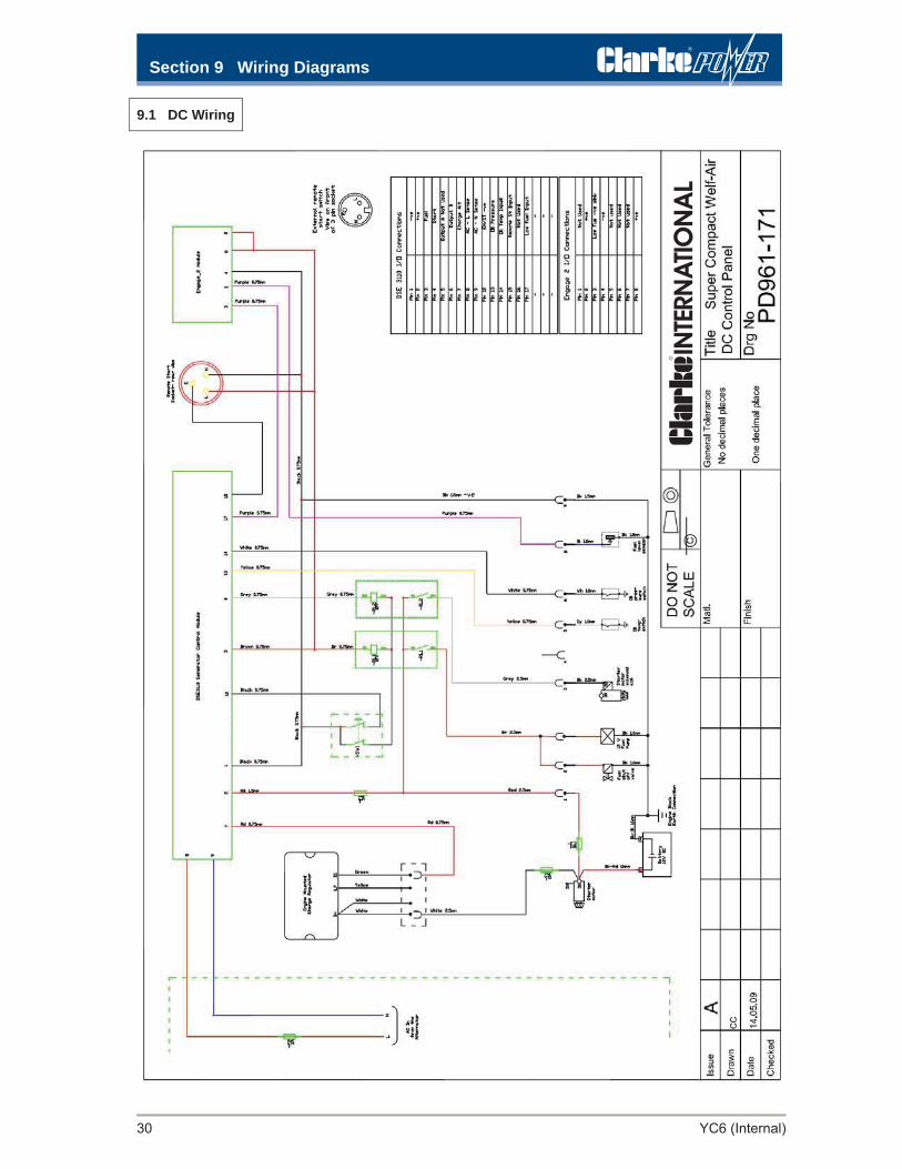
9.1 DC Wiring
Section 9 Wiring Diagrams

Section 9 Wiring Diagrams
YC6 (Internal) 31
9.2 AC Wiring
Section 9 Wiring Diagrams
32 YC6 (Internal)
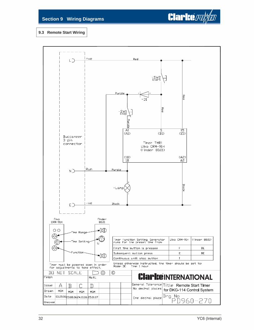
9.3 Remote Start Wiring

YC6 (Internal) 33
9.4 Remote Start Leads
Section 9 Wiring Diagrams

setoN 01 noitceS
34 YC6 (Internal)

Section 11 Warranty
YC6 (Internal) 35
WARRANTY STATEMENT
i) Goods to be returned to the local dealer/ supplier (or alternatively a site visit by dealer/
supplier at his option). All warrantable parts etc. and full technical support supplied FOC from the factory.
or: ii) Goods can be returned direct to our factory by the customer. Full parts and labour repairs
carried out in our workshops. Goods returned to customer at our expense. An order number will be required to cover non-warrantable work. A ‘Returns Number’ should be obtained prior to returning product.
Notes All parts supplied FOC are on condition that faulty parts are returned to the factory within 14 days of replacement and subject to factory examination for valid claims. Failures due to wear and tear and accidental damage are not covered. Equipment supplied for operation outside the UK mainland will normally be dealt as described in (i) or (iii) above. Limited warranty applies in special circumstances where equipment operates in extreme environmental conditions and/or for extended periods. Consult the factory. On-site and extended warranty terms are available. Please contact the factory for details. The Company will not be held responsible for consequential losses, or costs incurred by the customer during a warranty repair. The Company will not accept claims of compensation.
Issue A
Clarke Generators are covered by a 12 month or 1,000 hours warranty, whichever occurs the soonest for sets operating at 3000rpm. At 1500rpm generators are covered for 2000 hours or one year, whichever is the sooner. Where a product is to be used in adverse conditions or for prolonged duration, a shorter period may apply. This does not affect your statutory rights (Consumer Protection Axt 1987).
The manufacturer’s warranty will not apply in the following circumstances:
1. If the product has suffered customer or user abuse. 2. Damage by accident or deliberate misuse. 3. Lack of maintenance. 4. Failure to ensure the machine has received reasonable care and attention. 5. Fitment of unauthorized parts or accessories.
Contact Clarke International for instruction on an appropriate course of action for equipment failures during the warranty period. This may be one of the following;
Top Related