


Languages
Pages
Legal


Off Road Innovations
Design of an Off-Road Suspension and Steering System
EN 8926 - Mechanical Design Project II - Progress Report 1
Andrew Snelgrove 200832467
Calvin Holloway 200814416
Jeremy Sheppard 200907756
Kathleen Price 200735017

1
Acknowledgements
Off-Road Innovations would like to thank two individuals within the Engineering Department of Memorial University of Newfoundland whose time, assistance, and enthusiasm for our design project helped make this possible.
Professor Andy Fisher
Dr. Geoff Rideout
For your expertise and guidance throughout our project, thank you.


1
Contents 1 Introduction ............................................................................................................................ 4
1.1 The Baja Society of Automotive Engineers (SAE) Series .................................................. 4
1.2 The Memorial Baja Team ................................................................................................. 4
1.3 Off-Road Innovations ....................................................................................................... 4
2 Project Management Plan ...................................................................................................... 5
2.1 Project Goals .................................................................................................................... 5
2.2 Project Constraints ........................................................................................................... 5
2.3 Member Responsibilities .................................................................................................. 5
2.4 Project Schedule ............................................................................................................... 6
2.5 Team Communications .................................................................................................... 6
2.6 Risk Assessment ............................................................................................................... 6
3 Previous Generation Suspension and Steering Systems ........................................................ 7
3.1 Design ............................................................................................................................... 7
3.2 Front Suspension Arms .................................................................................................... 7
3.3 Shock Absorbers and Steering Knuckles .......................................................................... 7
3.4 Rack and Pinion System ................................................................................................... 9
3.5 Suspension and Steering Modeling and Simulation ........................................................ 9
4 Suspension and Steering Selection Validation...................................................................... 11
4.1 Suspension Concept Generation .................................................................................... 11
4.1.1 Swing Axle ............................................................................................................... 11
4.1.2 Double A-arm: ......................................................................................................... 12
4.1.3 MacPherson Strut ................................................................................................... 13
4.1.4 Trailing Arms ........................................................................................................... 14
4.2 Suspension Concept Selection ....................................................................................... 15
4.3 Steering Concept Generation ......................................................................................... 16
4.3.1 Manual Rack and Pinion ......................................................................................... 17
4.3.2 Manual Recirculating Ball ....................................................................................... 18
4.3.3 Hydraulic and Electric Power-Assisted Steering ..................................................... 19
4.4 Steering Concept Selection ............................................................................................ 21

2
5 Suspension and Steering Design ........................................................................................... 23
5.1 Redesign Scope .............................................................................................................. 23
5.2 Suspension and Steering Design Methodology ............................................................. 23
5.2.1 Wheel Alignment .................................................................................................... 24
5.2.2 Steering Geometry .................................................................................................. 28
5.3 Design Targets ................................................................................................................ 29
6 Moving Forward .................................................................................................................... 30
7 References ............................................................................................................................ 31
List of Figures
Figure 1: Suspension Mounting and Bushing Internals .................................................................. 7 Figure 2: Fox Float X Evolution Air Shocks ...................................................................................... 8 Figure 3: Front Suspension Set-Up ................................................................................................. 8 Figure 4: Swing Axle Suspension ................................................................................................... 12 Figure 5: Double A-arm on 2013 Memorial Baja .......................................................................... 13 Figure 6: Example of a MacPherson Strut .................................................................................... 14 Figure 7: Example of a Trailing Arms Suspension ......................................................................... 15 Figure 8: Manual Rack and Pinion on the Memorial Baja 2013 Car ............................................. 17 Figure 9: Cross-Section of a Recirculating Ball Gearbox Example ................................................ 18 Figure 10: Example of Complete Recirculating Ball Steering System with Pitman Arm ............... 18 Figure 11: Example of a Hydraulic Power-Assisted Steering Configuration ................................. 20 Figure 12: Wheelbase and Track ................................................................................................... 24 Figure 13: Positive and Negative Camber ..................................................................................... 25 Figure 14: Interplay between Steering Axis Inclination and Positive Camber (Front of Vehicle) 26 Figure 15: Toe-In and Toe-Out (View from Top of Vehicle).......................................................... 27 Figure 16: Negative and Positive Caster ....................................................................................... 27 Figure 17: Independent Front Suspension Steering and Suspension Geometry .......................... 28 Figure 18: Suspension Vector Model ............................................................................................ 30
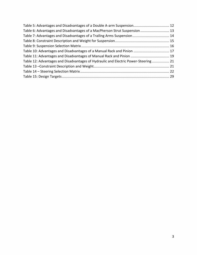
List of Tables
Table 1: Car Specifications .............................................................................................................. 9 Table 2: Drop Test ........................................................................................................................... 9 Table 3: Front Impact .................................................................................................................... 10 Table 4: Advantages and Disadvantages of a Swing Axle Suspension .......................................... 11
3
Table 5: Advantages and Disadvantages of a Double A-arm Suspension..................................... 12 Table 6: Advantages and Disadvantages of a MacPherson Strut Suspension .............................. 13 Table 7: Advantages and Disadvantages of a Trailing Arms Suspension ...................................... 14 Table 8: Constraint Description and Weight for Suspension ........................................................ 15 Table 9: Suspension Selection Matrix ........................................................................................... 16 Table 10: Advantages and Disadvantages of a Manual Rack and Pinion ..................................... 17 Table 11: Advantages and Disadvantages of Manual Rack and Pinion ........................................ 19 Table 12: Advantages and Disadvantages of Hydraulic and Electric Power-Steering .................. 21 Table 13 –Constraint Description and Weight .............................................................................. 21 Table 14 – Steering Selection Matrix ............................................................................................ 22 Table 15: Design Targets ............................................................................................................... 29

4
1 Introduction The purpose of the term 8 Mechanical Design project is to provide students with an opportunity to pursue an open-ended design project from start to finish. Students are required to develop a strategy for solving a problem, plan and manage, evaluate system design variations and develop a complete design documentation package. (Fisher, 2014)
For this design challenge, Off-Road Innovations was formed to redesign the Memorial Baja’s front suspension and steering systems.
1.1 The Baja Society of Automotive Engineers (SAE) Series The Baja SAE series is an international competition which test the limits of minimalistic racecars (Baja’s), designed and built by engineering students from over 100 universities. The competitions are geared toward simulating real-world engineering design projects and the challenges faced within them.
The Baja’s compete in static and dynamic events. Static events include ranking the students based on their design and vehicle costs. Dynamic events incorporate acceleration, suspension and traction, maneuverability, hill climb, rock crawl, mud pits and a four hour endurance race designed to push your vehicle to its limits through rough terrains.
All vehicles are required to use an identical ten-horsepower Intek Model 20 engine donated by Briggs & Stratton Corporation. Having all teams use the same engine creates a more challenging engineering design test. (Society of Automotive Engineers, 2014)
1.2 The Memorial Baja Team The Memorial Baja team is a group of engineering students from Memorial University that have been competing in the Baja SAE series since 2010. Over the past four years the Baja has developed and undergone many design changes with the key focus of maintaining a light, durable and competitive car.
1.3 Off-Road Innovations This design team of four Memorial University Engineering Students are each a part of the Memorial Baja competitive team. With past experience, passion for engineering and a commitment to the team, Off-Road Innovations is an unparalleled design group with the determination and capability to guarantee success.
To improve on previous Memorial Baja car performance, Off-Road Innovations has taken on the challenge of redesigning the front suspension and steering systems.

5
2 Project Management Plan Off-Road Innovations has selected a free form design group structure where a lead defines global milestones and objectives and responsibilities are given at a task-by-task basis. With this structure each member has the opportunity to contribute equally to all aspects of the project design where revisions are made as needed.
2.1 Project Goals Off-road Innovations goal is to develop an enhanced front suspension and steering system for the Memorial Baja team. The improved system will:
x Provide more driver room x Give a raised ride height x Lower forces transmitted in frontal impacts through recessional travel x Maintain previous reliability and low weight
These goals have to be met while still maintaining the reliability and low weight of the 2013 Baja design. In order for this goal to be met successfully all members of the team will play an intricate role to see the project through.
2.2 Project Constraints Design Constraints:
x Improve on original design as described in section 5.3. x Suspension must mount to 4130 steel tubing with 1¼” diameter. (SAE regulations)
Project Constraints:
x Must not exceed $250.00 budget x Project deliverables are to be completed on or before April 4, 2014.
2.3 Member Responsibilities Each member of Off-Road Innovations is committed to the following standards.
x Contribute an average of 5+ hours per week. x Participate equally in the writing of all reports and presentations x Engage with enthusiasm x Offer feedback and criticism where necessary x Play an active role by contributing at weekly review and design group meetings
6
2.4 Project Schedule A Gantt chart is used to facilitate easy viewing of the schedule and to ensure timely completion of all tasks. It provides understanding on how tasks are interrelated and helps to effectively allocate resources. The most recent Gantt chart can be seen in Appendix A.
2.5 Team Communications The team keeps an updated Website (www.OffroadInnovations.weebly.com), giving an overview of the members, projects and team goals. The website provides access to meeting minutes and the updated Gantt chart.
2.6 Risk Assessment
For every engineering problem, risk should be considered in the preliminary stages of the project. Associated risk for this project includes driver safety and the failure to complete the project before the required deadline. To mitigate these risks, the team will:
x Closely follow SAE Baja Competition Standards
x Follow Gantt chart and revise weekly
x Conversing daily
x Weekly Updates with Dr. Fisher

7
3 Previous Generation Suspension and Steering Systems The front suspension design of the Memorial Baja car has been consistent over the past few years since it has never caused problems due to its simplistic and practical design. However, since the Memorial Baja team has made such radical improvements to each aspect of the car each year, the current system requires optimization in order for the team to be an even more aggressive competitor.
3.1 Design The design of the 2013 Memorial Baja front suspension/steering systems is a fixed length double A-arm design with rack and pinion steering. The suspension system utilized the steering knuckle from a Polaris Outlaw 525 IRS and Fox Float Evolution shocks with 7” of travel.
3.2 Front Suspension Arms The bottom A-arms are comprised of 1” OD x 1/16” wall AISI 4130 ‘chromoly’ tubing. There are lower stresses in the top A-arm due to the shock mounting position so smaller tubing was selected, 3/4” x 1/16” AISI 1020 steel tubing.
The 1” OD A-arm pivots feature Delrin™ bushings, a spacer made of high-grade pre-ground drill rod (AISI A2 tool steel), and M8x65 grade 8.8 bolts. To reduce friction and maintenance a M6 grease fitting is used to allow lubrication of the sliding interface between the Delrin™ bushings and the polished drill rod spacer. This is modeled in Figure 1. The A-arms are mounted to the chassis with 1/8” 44W grade steel plate (similar to A36), cut out with a water jet cutter. All tabs were made identical in order to simplify fabrication and mass production
Figure 1: Suspension Mounting and Bushing Internals
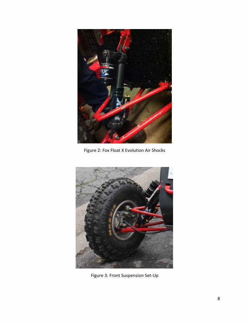
3.3 Shock Absorbers and Steering Knuckles The current front suspension utilizes Fox Float X Evolution air shocks see Figure 2. These shocks are lightweight and have adjustment capabilities. The shocks are inclined to give a wheel rate ranging from 58 lb/in up to 288 lb/in through its travel and mount to the bottom A-arms close to the steering knuckle. To mount the shocks, tabs were fabricated from 1/4” 44W grade steel and cut out with a water jet cutter. The steering knuckle used from the Polaris Outlaw 525 IRS can be viewed in Figure 3.
8
Figure 2: Fox Float X Evolution Air Shocks
Figure 3: Front Suspension Set-Up
9
3.4 Rack and Pinion System The rack and pinion steering system consists of two durable 19mm (3.4”) 1020 steel tie rods with a wall thickness of 1.5875mm (1/16”). These tire rods link the steering rack output to the front knuckles via ball joint and clevis connectors.
The steering column uses a double universal set up that bolts to the steering wheel and is coupled to the pinion shaft on the steering rack. The column is made of 25.4mm (1”) diameter 1020 steel tubing with a wall thickness of 1.5875mm (1/16”).
The rack has been designed with a lock to lock distance of 139.7mm (5.5”) achieved by a gear rotation of 530 degrees. To counteract thrust on the input shaft brought on by driver movement over rough terrain, the input shaft is held in place with internally pressed bushings. A grease fitting is used to allow for lubrication.
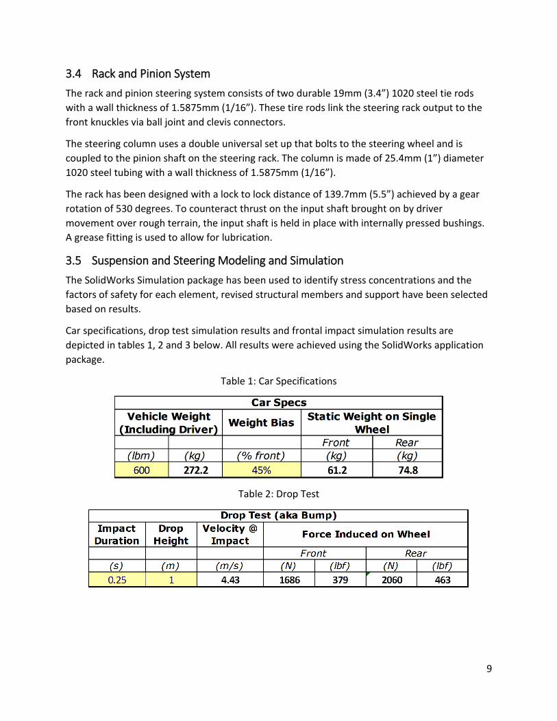
3.5 Suspension and Steering Modeling and Simulation The SolidWorks Simulation package has been used to identify stress concentrations and the factors of safety for each element, revised structural members and support have been selected based on results.
Car specifications, drop test simulation results and frontal impact simulation results are depicted in tables 1, 2 and 3 below. All results were achieved using the SolidWorks application package.
Table 1: Car Specifications
Table 2: Drop Test
10
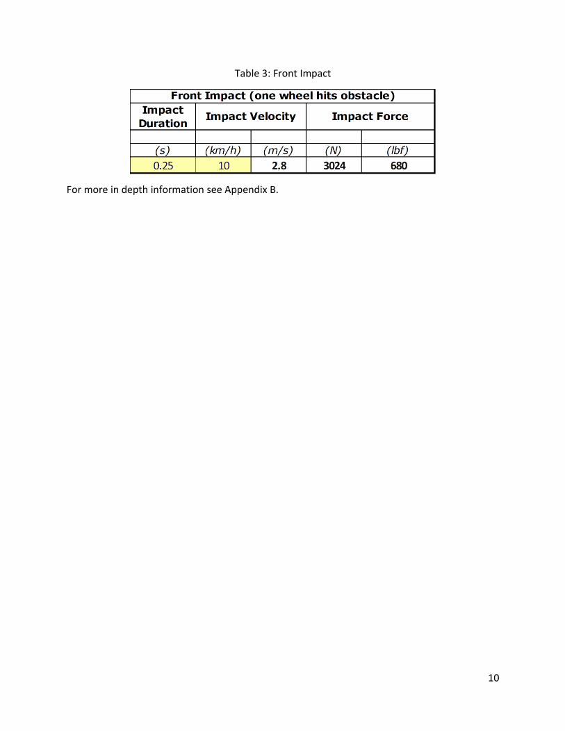
Table 3: Front Impact
For more in depth information see Appendix B.
11
4 Suspension and Steering Selection Validation To ensure that previous decisions regarding the suspension and steering system types were still preferable, a concept generation and selection phase of the project was carried out. After a number of systems were researched, weighted ranking was assigned to each to validate that the chosen system would best fit our needs.
4.1 Suspension Concept Generation The initial concept generation process resulted in four different types of suspension configurations. The following are the most commonly used in off-road applications:
x Swing Axle x Double A-arm (Double Wishbone) x MacPherson Strut x Trailing Link
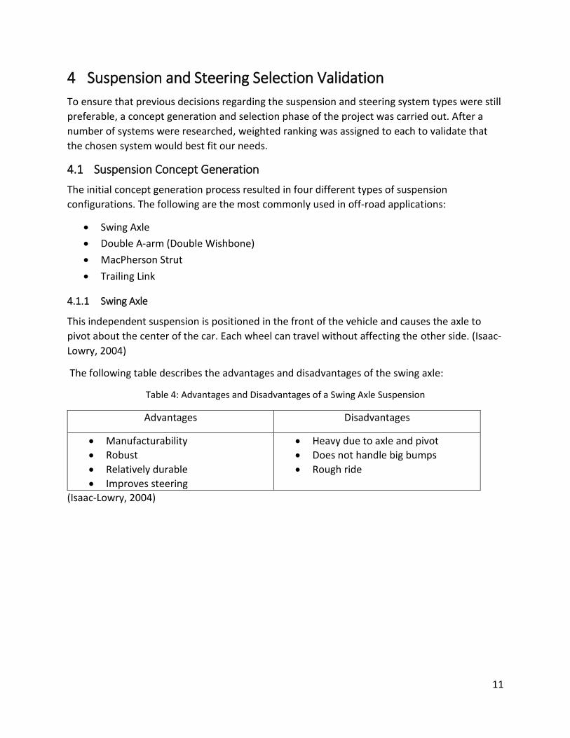
4.1.1 Swing Axle
This independent suspension is positioned in the front of the vehicle and causes the axle to pivot about the center of the car. Each wheel can travel without affecting the other side. (Isaac-Lowry, 2004)
The following table describes the advantages and disadvantages of the swing axle:
Table 4: Advantages and Disadvantages of a Swing Axle Suspension
Advantages Disadvantages
x Manufacturability x Robust x Relatively durable x Improves steering
x Heavy due to axle and pivot x Does not handle big bumps x Rough ride
(Isaac-Lowry, 2004)
12
Figure 4: Swing Axle Suspension
(Isaac-Lowry, 2004) (Date Accessed: Feb. 1st, 2014)
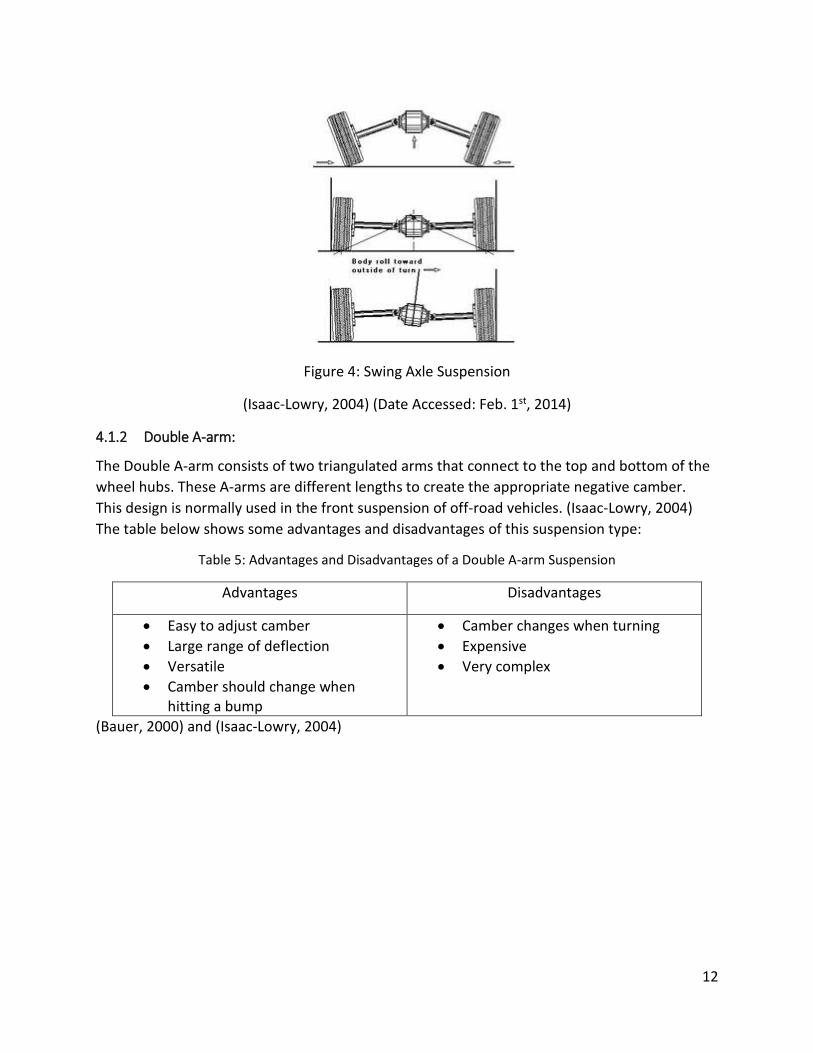
4.1.2 Double A-arm:
The Double A-arm consists of two triangulated arms that connect to the top and bottom of the wheel hubs. These A-arms are different lengths to create the appropriate negative camber. This design is normally used in the front suspension of off-road vehicles. (Isaac-Lowry, 2004) The table below shows some advantages and disadvantages of this suspension type:
Table 5: Advantages and Disadvantages of a Double A-arm Suspension
Advantages Disadvantages
x Easy to adjust camber x Large range of deflection x Versatile x Camber should change when
hitting a bump
x Camber changes when turning x Expensive x Very complex
(Bauer, 2000) and (Isaac-Lowry, 2004)
13
Figure 5: Double A-arm on 2013 Memorial Baja
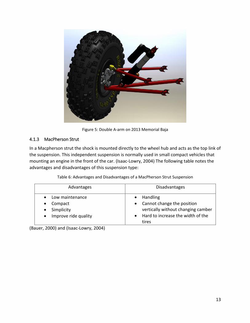
4.1.3 MacPherson Strut
In a Macpherson strut the shock is mounted directly to the wheel hub and acts as the top link of the suspension. This independent suspension is normally used in small compact vehicles that mounting an engine in the front of the car. (Isaac-Lowry, 2004) The following table notes the advantages and disadvantages of this suspension type:
Table 6: Advantages and Disadvantages of a MacPherson Strut Suspension
Advantages Disadvantages
x Low maintenance x Compact x Simplicity x Improve ride quality
x Handling x Cannot change the position
vertically without changing camber x Hard to increase the width of the
tires (Bauer, 2000) and (Isaac-Lowry, 2004)

14
Figure 6: Example of a MacPherson Strut
(Isaac-Lowry, 2004) (Date Accessed: Feb. 1st, 2014)_
4.1.4 Trailing Arms
In a Trailing Arms suspension, the links are ahead of the tire. This type of suspension is normally used in the rear of the car because it is hard to mount the links ahead of the tires in the front. Table 7 outlines some advantages and disadvantages of a trailing arms suspension:
Table 7: Advantages and Disadvantages of a Trailing Arms Suspension
Advantages Disadvantages
x Low cost x Small space requirements x Moves up and down with the
bumps in the road x Ride quality
x Normally used in rear suspension x Does not allow lateral or camber
change x Very bulky supports x Links bend when under significant
loading (Bauer, 2000), (Isaac-Lowry, 2004)
15
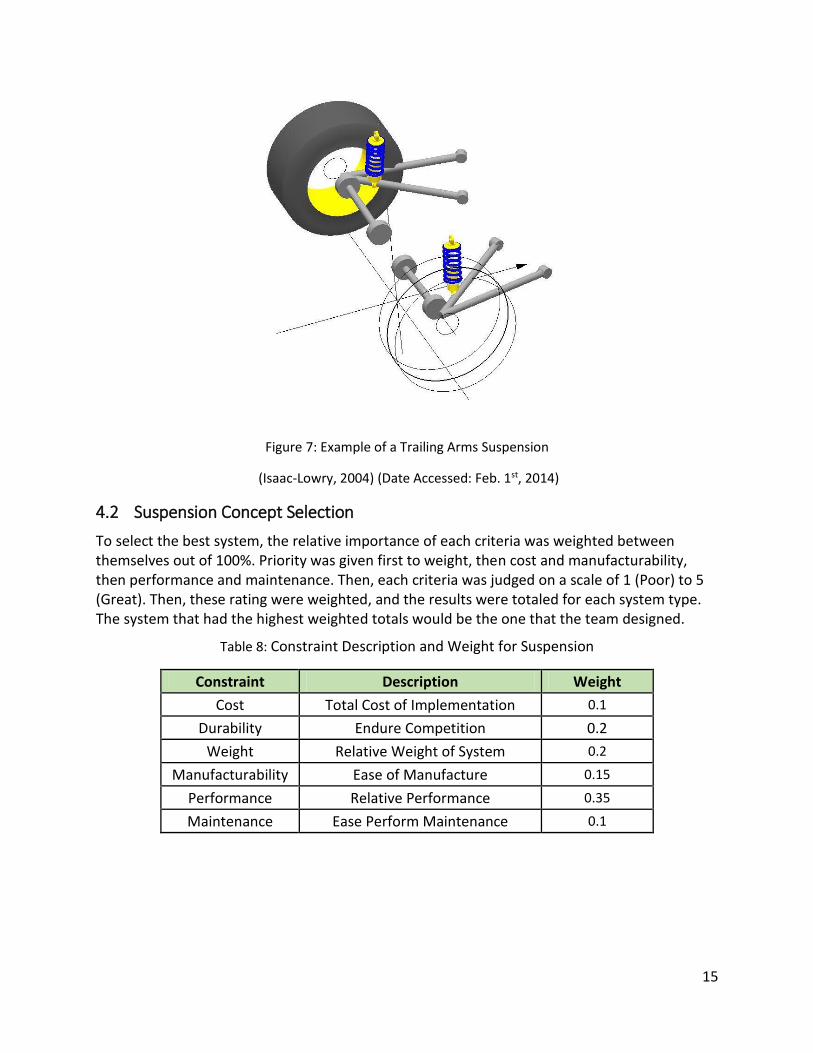
Figure 7: Example of a Trailing Arms Suspension
(Isaac-Lowry, 2004) (Date Accessed: Feb. 1st, 2014)
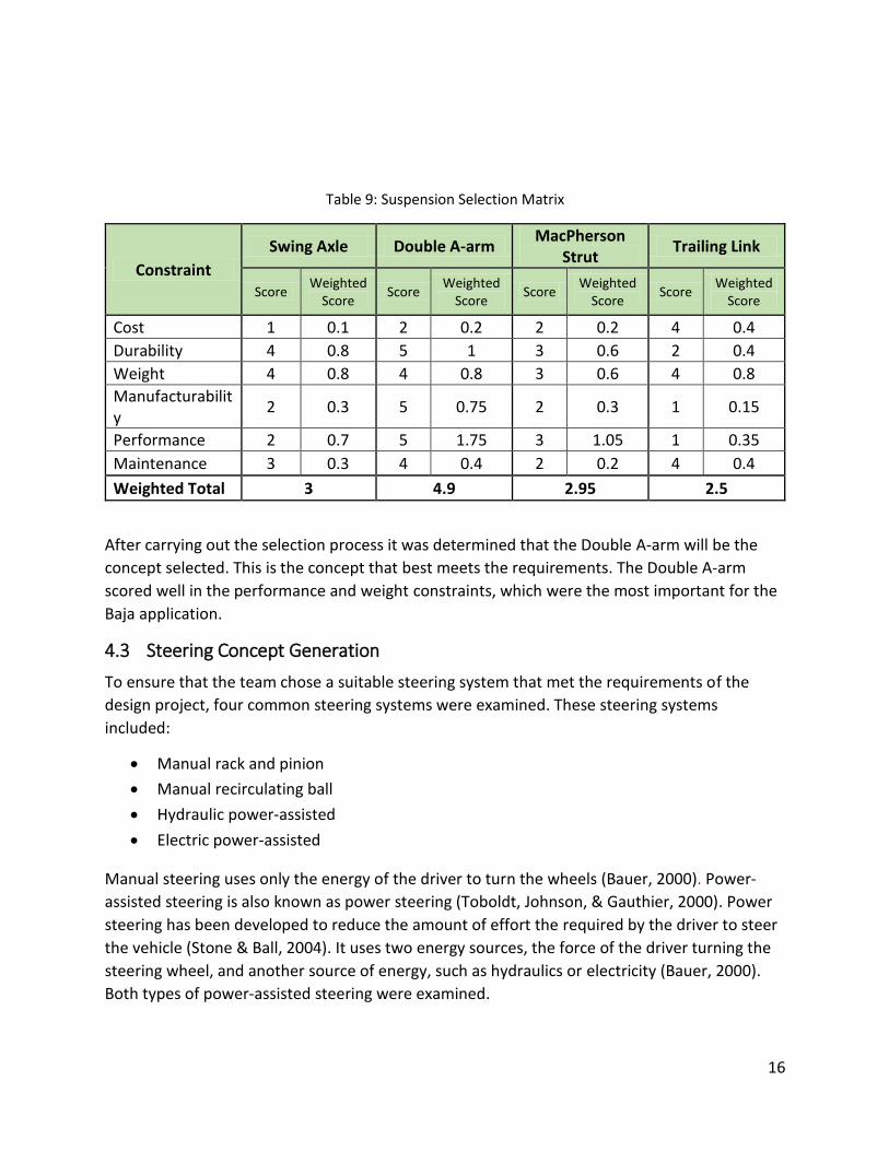
4.2 Suspension Concept Selection To select the best system, the relative importance of each criteria was weighted between themselves out of 100%. Priority was given first to weight, then cost and manufacturability, then performance and maintenance. Then, each criteria was judged on a scale of 1 (Poor) to 5 (Great). Then, these rating were weighted, and the results were totaled for each system type. The system that had the highest weighted totals would be the one that the team designed.
Table 8: Constraint Description and Weight for Suspension
Constraint Description Weight Cost Total Cost of Implementation 0.1
Durability Endure Competition 0.2 Weight Relative Weight of System 0.2
Manufacturability Ease of Manufacture 0.15 Performance Relative Performance 0.35 Maintenance Ease Perform Maintenance 0.1
16
Table 9: Suspension Selection Matrix
Constraint Swing Axle Double A-arm MacPherson
Strut Trailing Link
Score Weighted Score Score Weighted
Score Score Weighted Score Score Weighted
Score
Cost 1 0.1 2 0.2 2 0.2 4 0.4 Durability 4 0.8 5 1 3 0.6 2 0.4 Weight 4 0.8 4 0.8 3 0.6 4 0.8 Manufacturability 2 0.3 5 0.75 2 0.3 1 0.15
Performance 2 0.7 5 1.75 3 1.05 1 0.35 Maintenance 3 0.3 4 0.4 2 0.2 4 0.4 Weighted Total 3 4.9 2.95 2.5
After carrying out the selection process it was determined that the Double A-arm will be the concept selected. This is the concept that best meets the requirements. The Double A-arm scored well in the performance and weight constraints, which were the most important for the Baja application.
4.3 Steering Concept Generation To ensure that the team chose a suitable steering system that met the requirements of the design project, four common steering systems were examined. These steering systems included:
x Manual rack and pinion x Manual recirculating ball x Hydraulic power-assisted x Electric power-assisted
Manual steering uses only the energy of the driver to turn the wheels (Bauer, 2000). Power-assisted steering is also known as power steering (Toboldt, Johnson, & Gauthier, 2000). Power steering has been developed to reduce the amount of effort the required by the driver to steer the vehicle (Stone & Ball, 2004). It uses two energy sources, the force of the driver turning the steering wheel, and another source of energy, such as hydraulics or electricity (Bauer, 2000). Both types of power-assisted steering were examined.
17
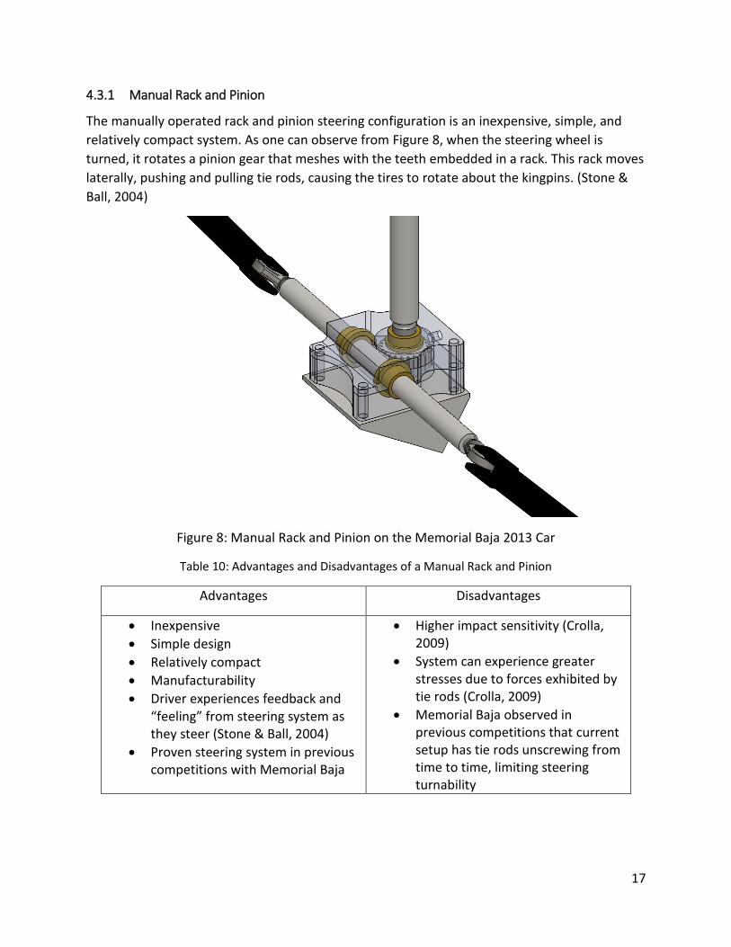
4.3.1 Manual Rack and Pinion
The manually operated rack and pinion steering configuration is an inexpensive, simple, and relatively compact system. As one can observe from Figure 8, when the steering wheel is turned, it rotates a pinion gear that meshes with the teeth embedded in a rack. This rack moves laterally, pushing and pulling tie rods, causing the tires to rotate about the kingpins. (Stone & Ball, 2004)
Figure 8: Manual Rack and Pinion on the Memorial Baja 2013 Car
Table 10: Advantages and Disadvantages of a Manual Rack and Pinion
Advantages Disadvantages
x Inexpensive x Simple design x Relatively compact x Manufacturability x Driver experiences feedback and
“feeling” from steering system as they steer (Stone & Ball, 2004)
x Proven steering system in previous competitions with Memorial Baja
x Higher impact sensitivity (Crolla, 2009)
x System can experience greater stresses due to forces exhibited by tie rods (Crolla, 2009)
x Memorial Baja observed in previous competitions that current setup has tie rods unscrewing from time to time, limiting steering turnability

18
4.3.2 Manual Recirculating Ball
Figure 9: Cross-Section of a Recirculating Ball Gearbox Example
(Nice, 2001) (Date Accessed: February 1st, 2014)
Figure 10: Example of Complete Recirculating Ball Steering System with Pitman Arm
(Nice, 2001) (Date Accessed: February 1st, 2014)
Another steering system configuration that was considered was the manual operation of the recirculating ball type. This configuration uses a combination of a nut and a worm gear. The nut

19
moves up and down the worm gear as the worm gear turns from the steering column. Ball bearings inside the box “recirculate” around the worm gear, reducing wear on the gear. (Stone & Ball, 2004)
As the nut moves up and down the worm gear, it causes the pitman arm to rotate left or right about a fixed axis, therefore pushing and pulling the track and tie rods to turn the wheels appropriately. (Nice, 2001)
Table 11: Advantages and Disadvantages of Manual Rack and Pinion
Advantages Disadvantages
x Steering effort by driver is reduced. (Stone & Ball, 2004)
x More complicated than rack and pinion. (Crolla, 2009)
x More expensive than rack and pinion. (Crolla, 2009)
x No feedback or steering “feeling” experienced by driver. (Stone & Ball, 2004)
4.3.3 Hydraulic and Electric Power-Assisted Steering
Hydraulic and electric energy are examples of alternative sources of energy that can assist a driver in turning their front wheels. Hydraulic power-assisted steering uses fluid from a reservoir and a pump to assist in pushing the tire wheels (AGCO Automotive Coporation, 2014). Alternatively, in electric power-assisted steering, an electric motor can assist in turning the wheels (Levine, 2010). As shown below in the figures, they can be used in combinations similar to a rack and pinion setup.

20
Figure 11: Example of a Hydraulic Power-Assisted Steering Configuration
(AGCO Automotive Coporation, 2014) (Date Accessed: February 1st, 2014)
Example of an Electric Power-Assisted Steering Configuration
(Levine, 2010) (Date Accessed: February 1st, 2014)
21
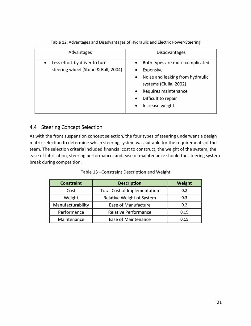
Table 12: Advantages and Disadvantages of Hydraulic and Electric Power-Steering
Advantages Disadvantages
x Less effort by driver to turn steering wheel (Stone & Ball, 2004)
x Both types are more complicated x Expensive x Noise and leaking from hydraulic
systems (Ciulla, 2002) x Requires maintenance x Difficult to repair x Increase weight
4.4 Steering Concept Selection As with the front suspension concept selection, the four types of steering underwent a design matrix selection to determine which steering system was suitable for the requirements of the team. The selection criteria included financial cost to construct, the weight of the system, the ease of fabrication, steering performance, and ease of maintenance should the steering system break during competition.
Table 13 –Constraint Description and Weight
Constraint Description Weight Cost Total Cost of Implementation 0.2
Weight Relative Weight of System 0.3
Manufacturability Ease of Manufacture 0.2
Performance Relative Performance 0.15
Maintenance Ease of Maintenance 0.15
22
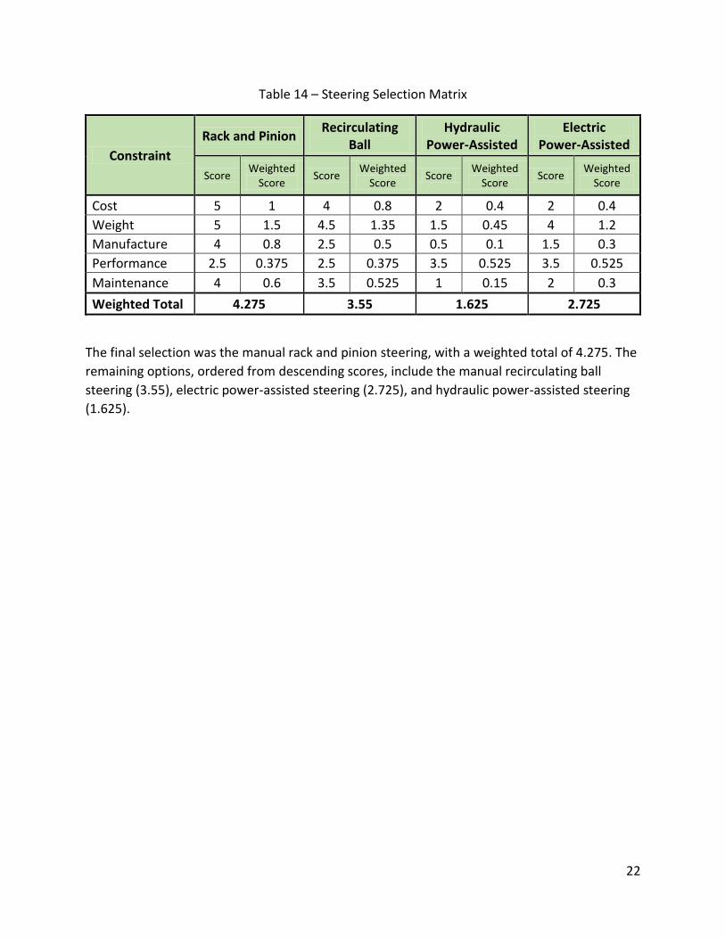
Table 14 – Steering Selection Matrix
Constraint Rack and Pinion Recirculating
Ball Hydraulic
Power-Assisted Electric
Power-Assisted
Score Weighted Score Score Weighted
Score Score Weighted Score Score Weighted
Score
Cost 5 1 4 0.8 2 0.4 2 0.4 Weight 5 1.5 4.5 1.35 1.5 0.45 4 1.2 Manufacture 4 0.8 2.5 0.5 0.5 0.1 1.5 0.3 Performance 2.5 0.375 2.5 0.375 3.5 0.525 3.5 0.525 Maintenance 4 0.6 3.5 0.525 1 0.15 2 0.3 Weighted Total 4.275 3.55 1.625 2.725
The final selection was the manual rack and pinion steering, with a weighted total of 4.275. The remaining options, ordered from descending scores, include the manual recirculating ball steering (3.55), electric power-assisted steering (2.725), and hydraulic power-assisted steering (1.625).
23
5 Suspension and Steering Design Off road vehicles pose an interesting design problem for engineers due to the long suspension travel and low wheel rates. Baja vehicles introduce a number of design difficulties merited by many parameter and behavioral interactions. In context, the amount of suspension travel for the Baja vehicle is over twice that of typical passenger cars. With such significant travel, strong consideration must be given to how the tire is moving relative to the ground during travel. The very small engine type causes any inefficiency that are present to greatly affect the performance of the vehicle.
5.1 Redesign Scope Using the collective information and field experience that the team has developed, a new suspension and steering system will be engineered with enhancements including more recessional travel and caster angle, greater driver ergonomics and other general performance enhancements. The redesign work will be focused on system geometry and placement as well as ensuring previous reliability and performance targets are met or exceeded.
Due to time and financial limitations, some components will be outside the scope of the redesign work and include:
x Front wheels x Hubs x Knuckle assembly x Shocks x A-arm bushings of the suspension system x Rack and pinion aluminum mount
With these restrictions in place the components to be designed include:
x A-arm structural member types and material x Upper and lower A-arm geometry x Tie rod material and geometry x Steering column x Chassis mounting locations x Rack and pinion geometry and locations x Rack and pinion bushing material x Rack and pinion bushing design
5.2 Suspension and Steering Design Methodology The first objective is to have all the tires turn around a centurial point. This is important because it prevents the tire from scuffing and creating premature tire wear. To get the proper

24
geometry the Ackerman angle needs to be considered. Below is the formulas used to calculate the offset of the outside front tire and inside front tire:
δo = (1)
δi = (2)
δo – Ackerman angle outside tire δi – Ackerman angle inside tire
L – wheelbase R – turn radius t – track width
(Stone & Ball, 2004) Figure 12 below outlines the meaning of wheelbase and track:
Figure 12: Wheelbase and Track
(Wheelbase, 2013) (Date Accessed: February 1st, 2014)
5.2.1 Wheel Alignment
Wheel alignment is very important for the handling of the Baja. If you have the tire aligned properly the car should drive straight without any input from the driver. The components of wheel alignment include:
x Camber x Steering axis inclination x Toe
25
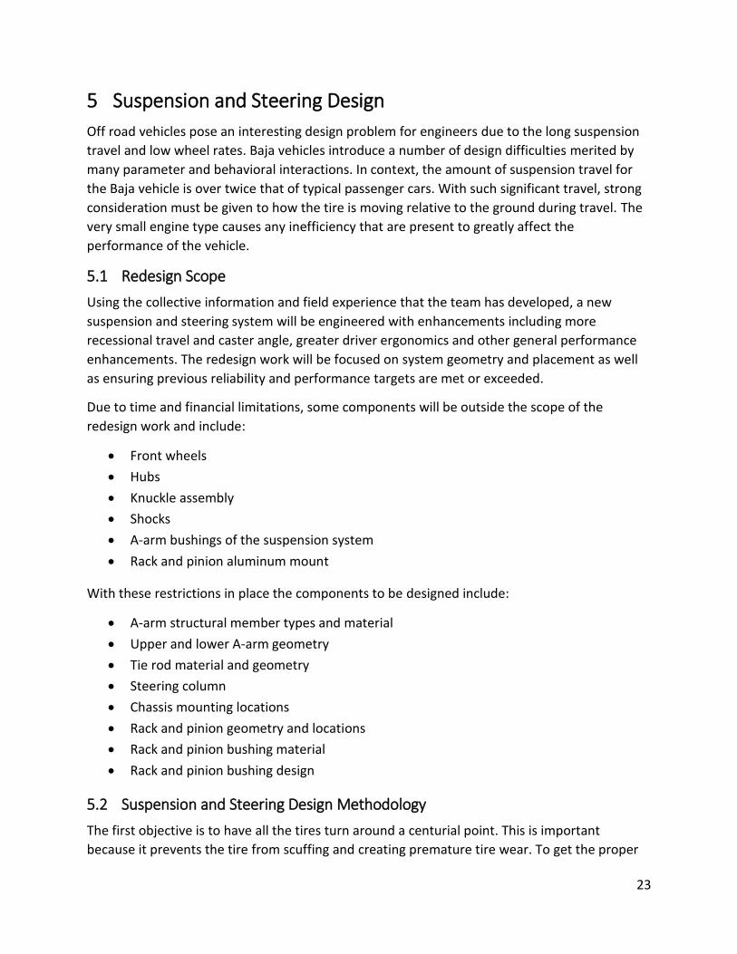
x Caster
Camber is the angle of the tire in the vertical direction. A car can have positive camber, this is when the top of the tire is farther away from the car. Alternatively a car can have negative camber, when the top of the wheel is closer to the car. Negative camber is normally used in off-road vehicle because it enhances tire engagement with the ground when maneuvering around turns. (Stone & Ball, 2004)
Figure 13: Positive and Negative Camber
(Adapted from: (July Subaru of Keene Service Specials, n.d.)) (Date Accessed: February 5th, 2014)
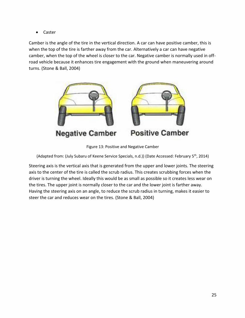
Steering axis is the vertical axis that is generated from the upper and lower joints. The steering axis to the center of the tire is called the scrub radius. This creates scrubbing forces when the driver is turning the wheel. Ideally this would be as small as possible so it creates less wear on the tires. The upper joint is normally closer to the car and the lower joint is farther away. Having the steering axis on an angle, to reduce the scrub radius in turning, makes it easier to steer the car and reduces wear on the tires. (Stone & Ball, 2004)
26
Figure 14: Interplay between Steering Axis Inclination and Positive Camber (Front of Vehicle)
(Stone & Ball, 2004)
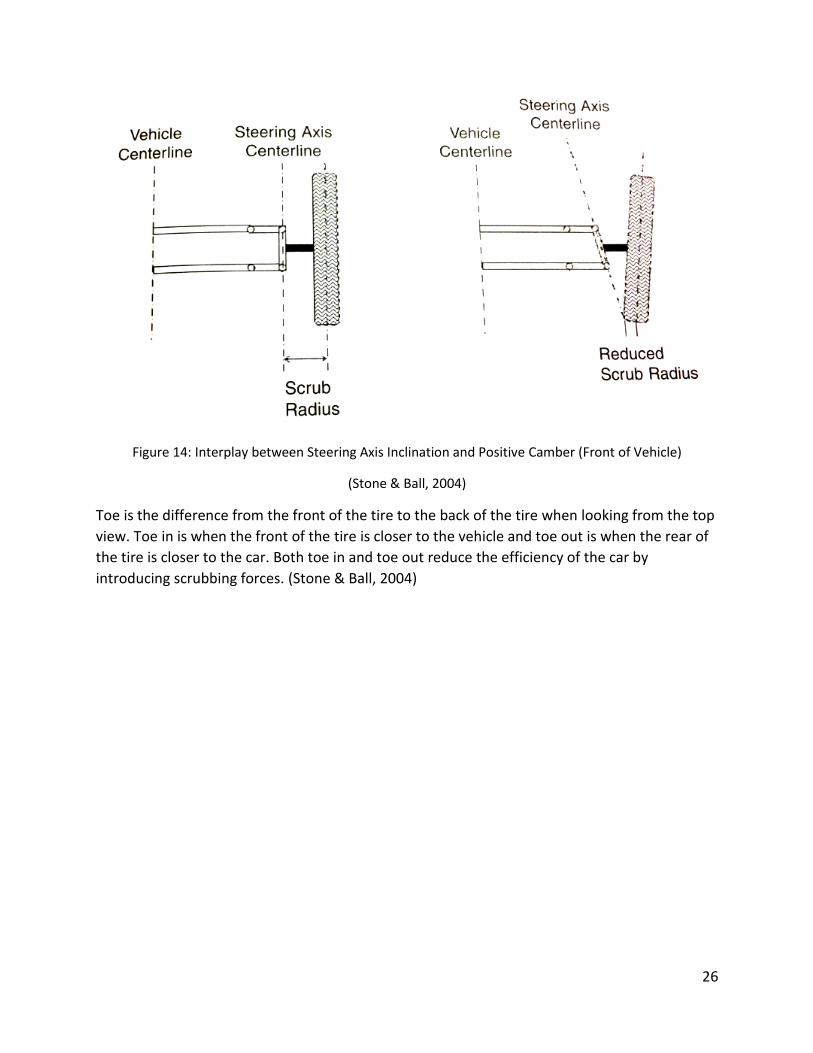
Toe is the difference from the front of the tire to the back of the tire when looking from the top view. Toe in is when the front of the tire is closer to the vehicle and toe out is when the rear of the tire is closer to the car. Both toe in and toe out reduce the efficiency of the car by introducing scrubbing forces. (Stone & Ball, 2004)

27
Figure 15: Toe-In and Toe-Out (View from Top of Vehicle)
(Stone & Ball, 2004)
Caster is the angle of the steering axis viewed from the side. Positive caster is when the upper joint is farther to the rear of the car. Negative caster is when the steering axis is inclining towards the front of the car. Having positive caster is desirable because it provides a more stable ride and helps with aligning the wheels to drive in a straight line. When designing the caster of the system, the steering axis should intersect with the ground before the tire contact patch. (Stone & Ball, 2004)
Figure 16: Negative and Positive Caster
(Adapted From: (July Subaru of Keene Service Specials, n.d.)) (Date: Accessed: February 5th, 2014)
28
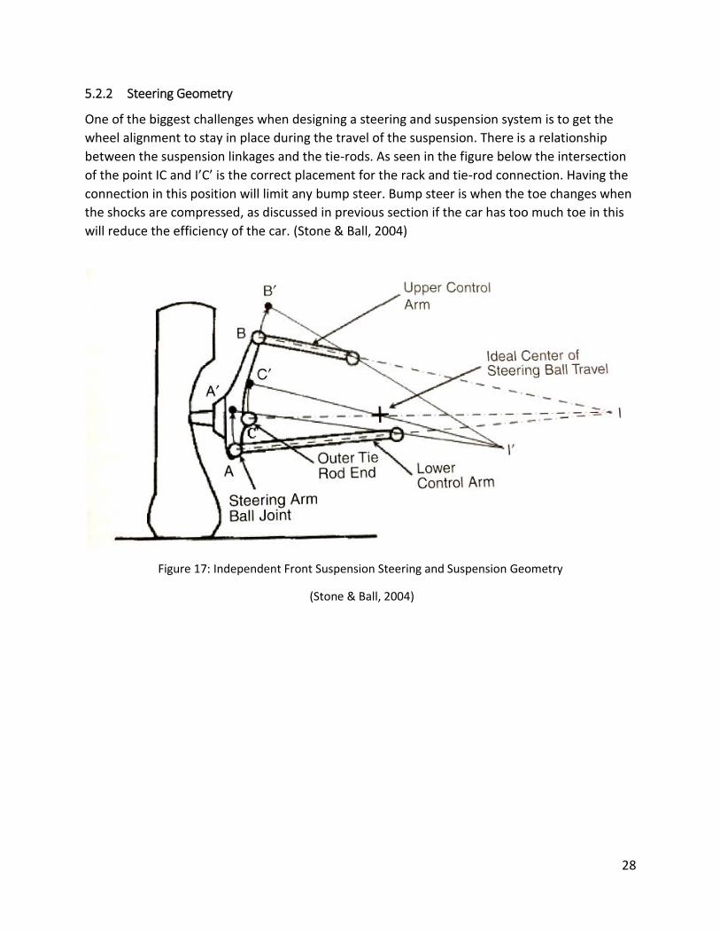
5.2.2 Steering Geometry
One of the biggest challenges when designing a steering and suspension system is to get the wheel alignment to stay in place during the travel of the suspension. There is a relationship between the suspension linkages and the tie-rods. As seen in the figure below the intersection of the point IC and I’C’ is the correct placement for the rack and tie-rod connection. Having the connection in this position will limit any bump steer. Bump steer is when the toe changes when the shocks are compressed, as discussed in previous section if the car has too much toe in this will reduce the efficiency of the car. (Stone & Ball, 2004)
Figure 17: Independent Front Suspension Steering and Suspension Geometry
(Stone & Ball, 2004)

29
5.3 Design Targets Using the overall results from the previous Memorial Baja car new design targets have been discussed and decided upon by the team. The targets set include:
Table 15: Design Targets
30
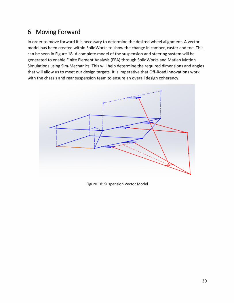
6 Moving Forward In order to move forward it is necessary to determine the desired wheel alignment. A vector model has been created within SolidWorks to show the change in camber, caster and toe. This can be seen in Figure 18. A complete model of the suspension and steering system will be generated to enable Finite Element Analysis (FEA) through SolidWorks and Matlab Motion Simulations using Sim-Mechanics. This will help determine the required dimensions and angles that will allow us to meet our design targets. It is imperative that Off-Road Innovations work with the chassis and rear suspension team to ensure an overall design coherency.
Figure 18: Suspension Vector Model

31
7 References AGCO Automotive Coporation. (2014). AGCO. Retrieved January 20, 2014, from
http://www.agcoauto.com/content/news/p2_articleid/214
Bauer, H. (Ed.). (2000). Automotive Handbook. 5. Stuttgart, Germany: Robert Bosch GmbH.
Ciulla, V. T. (2002). Power Steering. Retrieved February 6, 2014, from About.com: http://autorepair.about.com/cs/generalinfo/l/bldef_628.htm
Crolla, D. A. (Ed.). (2009). Automotive Engineering: Powertrain, Chassis System and Vehicle Body. Amsterdam: Butterworth-Heinemann (Elsevier Science & Technology Books, Inc./Elsevier Inc.). Retrieved January 20, 2014, from http://library.books24x7.com/toc.aspx?bookid=37287 (Accessed through Books24x7 Engineering Pro Collection through Memorial University of Newfoundland Library Online)
Fisher, A. (2014). ENGI 8926 Course Outline. Memorial University. Retrieved January 15, 2014, from online.mun.ca
Isaac-Lowry, J. (2004, August 22). Suspension Design: Types of Suspensions. Retrieved from Automotive Articles: http://www.automotivearticles.com/Suspension_Design_Types_of_Suspensions.shtml
July Subaru of Keene Service Specials. (n.d.). Retrieved February 5, 2014, from Subaru (subaruofkeene.com): http://www.subaruofkeene.com/specials/service.htm
Levine, M. (2010, May 31). Driving a Pickup with Electric Power Steering. Retrieved February 1, 2014, from PickupTrucks.com: http://news.pickuptrucks.com/2010/05/driving-a-pickup-with-electric-power-steering.html
Nice, K. (2001, May 31). How Car Steering Works (Recirculating-ball Steering Section). Retrieved February 1, 2014, from HowStuffWorks.com: http://auto.howstuffworks.com/steering3.htm
Society of Automotive Engineers. (2014). SAE Collegiate Design Series. Retrieved January 26, 2014, from SAE International: http://students.sae.org/cds/bajasae/about.htm
Stone, R., & Ball, J. K. (2004). Automotive Engineering Fundamentals. Warrendale: SAE International.
Toboldt, W. K., Johnson, L., & Gauthier, W. S. (2000). Automotive Encyclopedia: Fundamental Principles, Operation, Construction, Service, and Repair. Tinley Park: The Goodheart-Willcox Company, Inc.
Wheelbase. (2013, December 17). Retrieved February 1, 2014, from Wikipedia: http://en.wikipedia.org/wiki/Wheelbase

i
Appendix A – Project Gantt Chart

ii
Appendix B – Detailed Memorial Baja Specifications
Suspension Parameters Front Suspension Type Dual unequal length A-Arm, Fox Float X EVO air shocks.
Tire Size and Type *24x6-10 MAXXIS R2 Wheels (width, construction) *6" wide, Forged Al, 4/2 offset Center of Gravity Design Height 17"-18" ( 442mm) above ground Vertical Wheel Travel (over the travel) 7" (178 mm) jounce/ 5.4" (137 mm) rebound Recessional Wheel travel (over the travel) 0" (0mm)
Total track change (over the travel) 1.2" (30.5mm)
Wheel rate (chassis to wheel center) 58 lbs/in (10 N/mm) initial; 288 lbs/in (50 N/mm) high impact (adjustable); (progressive airshock, 2 linear approximations)
Spring Rate 200 lbs/in (35 N/mm) Initial; 800 lbs/in (140 N/mm) High Impact (adjustable); (progressive airshock, 2 linear approximations)
Motion ratio / type 0.57 average 0.54-0.6 actual progressive rate Roll rate (chassis to wheel center) 6.4 degrees per g Sprung mass natural frequency 1.2 Hz (Fully Adjustable) Type of Jounce Damping Low speed adjustable Type of Rebound Damping Low Speed adjustable Roll Camber (deg / deg) 0.86 deg / deg Static Toe 2 deg Toe change (over the travel) 1 deg Static camber and adjustment method 5 deg inward, adj. via outboard rod end on A-arm Camber Change (over the travel) 6 degrees Static Caster Angle 7 deg Caster Change (over the travel) 0 deg Kinematic Trail 1.7" Static Kingpin Inclination Angle 8 degrees non-adjustable Static Kingpin Offset 0.92" (23.4mm) Static Scrub Radius -1.7" (-43.2mm) Static Percent Ackermann 40% Percent Anti dive / Anti Squat 0% Anti dive Static Roll Center Position 6.3" (160mm) above ground Number of steering wheel turns lock to lock 2 Outside Turn Radius 11' ( 3.3m) to right
Top Related