


Languages
Pages
Legal


ODU-MINI-SNAPSeries S - IP50 and IP68
FP-Locking ConceptKeying with Insulation Body
Seri
es S

Page 96 ODU-Steckverbindungssysteme GmbH & Co. KG, Pregelstr. 11, D-84453 Mühldorf/Inn, Tel. +49/86 31/61 56-0, Fax +49/86 31/61 56 49, www.odu.de
ODU-MINI-SNAP Series S
The Push-Pull Locking Principle: FP
Locking Groove Locking Fingers Back Nut
Conical SleeveOuter Housing
ODU-MINI-SNAP connectorin unmated condition.
ODU-MINI-SNAP connector inmated condition.
Pulling on the cable or on the backnut causes the locking fingers to griptighter into the groove inside thereceptacle. A separation is virtuallyimpossible.
Pulling on the outer plug housingdisengages the locking fingers fromthe receptacle groove and theconnector separates easily.
Receptacle Plug

ODU-Steckverbindungssysteme GmbH & Co. KG, Pregelstr. 11, D-84453 Mühldorf/Inn, Tel. +49/86 31/61 56-0, Fax +49/86 31/61 56 49, www.odu.de Page 97
Collet Nut
Cable
EMI Ring
Shield
Inner Housing
Single Conductor
Contacts
Back Nut
Half Shells
Locking Finger
Locking Groove
Insulator
Hex Nut
Contacts
Outer Housing
Insulator
Conical Sleeve
Housing
Lamella
Locking Ring
Guide Ring
Press Ring
ODU-MINI-SNAPPlug
ODU-MINI-SNAPReceptacle
ODU-MINI-SNAPwith FP-Locking Scheme in Cross Section
Series S ODU-MINI-SNAP

Page 98 ODU-Steckverbindungssysteme GmbH & Co. KG, Pregelstr. 11, D-84453 Mühldorf/Inn, Tel. +49/86 31/61 56-0, Fax +49/86 31/61 56 49, www.odu.de
Available Housing Sizes(Scale 1 : 1)
OD = Outside Diameter (Plug)S = Size
0 1 2
9,412 15
OD:
S:
ODU-MINI-SNAP Series S

ODU-Steckverbindungssysteme GmbH & Co. KG, Pregelstr. 11, D-84453 Mühldorf/Inn, Tel. +49/86 31/61 56-0, Fax +49/86 31/61 56 49, www.odu.de Page 99
Series S ODU-MINI-SNAP
Part Number Key
Example:
Receptacle - Style 5 - Size 2 - Series S - Brass matt chromate Housing -PBT Insulator - 8pos. - Socket & Pin (solder) 0,75 µm Au -Term. Cross Section AWG22
Plug - Style 2 - Size 2 - Series S - Brass matt chromate Housing - PBT Insulator - 8pos. - Pin & Socket (solder) 0,75 µm Au - Term. Cross Section AWG22 - Cable Diameter 7.1-7.5 -Blue Cable Bend Relief - Material PUR
The Part Number Key
1. Type G = Receptacle
K = In-Line Receptacle
S = Straight Plug
2. Style 1 - 9 and A - Z
X = Special
3. Size 0 - 2
4. Series S
5. Coding 0
6. Material/Surface - Housing (Page 112)
7. empty
8. Material - Insulator (Page 112)
9. + 10. Contact Insert (Page 107-110)
e.g. 18-way = 8
11. Contact Type/Surface (Page 113)
12. Contact Diameter (Page 113)
M = mixed arrangement
13. + 14. Term. Cross Section (Page 114)
14. for special Contact Configurations 9
15. empty
16. + 17. Collet System (Page 115)
18. + 19. Cable Bend Relief (Page 116)
1 2 3 4 5 6 7 8 9 10 11 12 13 14 15 16 17 18 19
S 0
1 2 3 4 5 6 7 8 9 10 11 12 13 14 15 16 17 18 19
G 5 2 S 0 C T 0 8 L J G 0 0 0 0 0
1 2 3 4 5 6 7 8 9 10 11 12 13 14 15 16 17 18 19
S 2 2 S 0 C T 0 8 M J G 0 7 5 E P

Page 100 ODU-Steckverbindungssysteme GmbH & Co. KG, Pregelstr. 11, D-84453 Mühldorf/Inn, Tel. +49/86 31/61 56-0, Fax +49/86 31/61 56 49, www.odu.de
ODU-MINI-SNAP Series S
1 2 3 4 5 6 7 8 9 10 11 12 13 14 15 16 17 18 19
S 0
Part Number Key
S - IP 50 – with Standard Back Nut
S 2
1
S 1
S 2
S 3
S 4
- IP 50 – with Back Nut for Cable Bend Relief
IP 50 IP 68
S 3 - IP 68 – watertight with Standard Back Nut
S 4 - IP 68 – watertight with Back Nut for Cable Bend Relief
Straight Plug (Suitable for all following receptacles and in-line receptacles)
D
SW-B
L1
L2SW-A
D
SW-B
L1
L2SW-A
Contact configuration from page 107
D
SW-B
L1
L2SW-A
D
SW-B
L1
L2SW-A
Dimensions in mmSize L1 L2 D SW-A SW-B
0 ~ 37 ~ 28 9,4 8 71 ~ 47 ~ 35 12 10 102 ~ 50 ~ 38 15 13 12
Dimensions in mmSize L1 L2 D SW-A SW-B
0 ~ 40 ~ 30 9,4 8 71 ~ 49 ~ 38 12 10 102 ~ 53 ~ 40 15 13 12

ODU-Steckverbindungssysteme GmbH & Co. KG, Pregelstr. 11, D-84453 Mühldorf/Inn, Tel. +49/86 31/61 56-0, Fax +49/86 31/61 56 49, www.odu.de Page 101
1 2 3 4 5 6 7 8 9 10 11 12 13 14 15 16 17 18 19
S 0 0
Part Number Key
A - IP 50 – with hex nut, non latchingA
A A
Panel-Mounted Plug (Suitable for all following receptacles and in-line receptacles)
D
SW-ASW-B
L3
L1
L2
Contact configuration from page 27
SW
ØDimensions in mm PanelSize L1 L2 L3 D SW-A SW-B Cut-Out
0 17 5,8 24,5 10 8,2 11 SW 8,3 / Ø 9,11 22,3 10 29,5 14 10,5 14 SW 10,6 / Ø 12,12 23,5 9,7 31,5 18 13,5 17 SW 13,6 / Ø 15,13 29 12 33 22 16,5 22 SW 16,6 / Ø 18,1
Series S ODU-MINI-SNAP

Page 102 ODU-Steckverbindungssysteme GmbH & Co. KG, Pregelstr. 11, D-84453 Mühldorf/Inn, Tel. +49/86 31/61 56-0, Fax +49/86 31/61 56 49, www.odu.de
1 2 3 4 5 6 7 8 9 10 11 12 13 14 15 16 17 18 19
S 0
Part Number Key
K - IP 50 – with Standard Back Nut
K 2
1
K 1
K 2
K 3
K 4
- IP 50 – with Back Nut for Cable Bend Relief
IP 50 IP 68
K 3 - IP 68 – watertight with Standard Back Nut
K 4 - IP 68 – watertight with Back Nut for Cable Bend Relief
In-Line Receptacle
Contact configuration from page 107
Dimensions in mmSize L1 D SW-A SW-B
0 ~ 36 10 8 71 ~ 43 12 10 102 ~ 50 15 13 12
D
SW-B
L1
SW-A
D
SW-B
L1
SW-A
D
SW-B
L1
SW-A
D
SW-B
L1
SW-A
Dimensions in mmSize L1 D SW-A SW-B
0 ~ 40 10 8 71 – – – –2 ~ 51 16 13 12
ODU-MINI-SNAP In-Line Receptacle connect to plug for cable-to-cable connection.
ODU-MINI-SNAP Series S
ODU-Steckverbindungssysteme GmbH & Co. KG, Pregelstr. 11, D-84453 Mühldorf/Inn, Tel. +49/86 31/61 56-0, Fax +49/86 31/61 56 49, www.odu.de Page 103
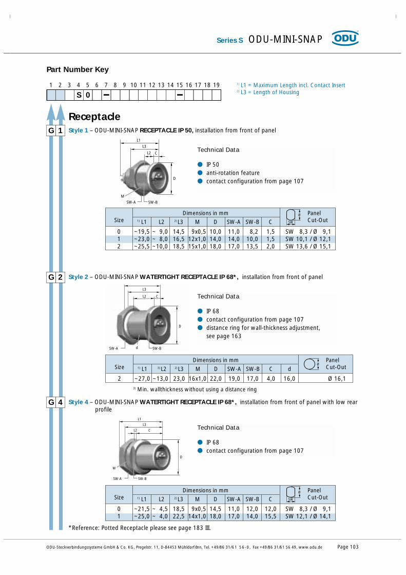
0 ~19,5 ~ 9,0 14,5 9x0,5 10,0 11,0 8,2 1,5 SW 8,3 / Ø 9,11 ~23,0 ~ 8,0 16,5 12x1,0 14,0 14,0 10,0 1,5 SW 10,1 / Ø 12,12 ~25,5 ~10,0 18,5 15x1,0 18,0 17,0 13,5 2,0 SW 13,6 / Ø 15,1
Dimensions in mm PanelSize 1) L1 L2 2) L3 M D SW-A SW-B C Cut-Out
0 ~21,5 ~ 4,5 18,5 9x0,5 14,5 11,0 12,0 12,0 SW 8,3 / Ø 9,11 ~25,0 ~ 4,0 22,5 14x1,0 18,0 17,0 14,0 15,5 SW 12,1 / Ø 14,1
1 2 3 4 5 6 7 8 9 10 11 12 13 14 15 16 17 18 19
S 0
Part Number Key
G Style 1 – ODU-MINI-SNAP RECEPTACLE IP 50, installation from front of panel1
1) L1 = Maximum Length incl. Contact Insert2) L3 = Length of Housing
Technical Data
● IP 50 ● anti-rotation feature● contact configuration from page 107D
SW-B
M
SW-A
L2 C
L3
L1
G Style 2 – ODU-MINI-SNAP WATERTIGHT RECEPTACLE IP 68*, installation from front of panel2
Ø
Technical Data
● IP 68● contact configuration from page 107● distance ring for wall-thickness adjustment,
see page 163
D
SW-A
CL2
d
L3
SW-B
G Style 4 – ODU-MINI-SNAP WATERTIGHT RECEPTACLE IP 68*, installation from front of panel with low rearprofile
4
SW
Ø
Technical Data
● IP 68● contact configuration from page 107
D
SW-A
M
L3
L1
CL2
SW-B
2 ~27,0 ~13,0 23,0 16x1,0 22,0 19,0 17,0 4,0 16,0 Ø 16,1
Dimensions in mm PanelSize 1) L1 3) L2 2) L3 M D SW-A SW-B C d Cut-Out
Dimensions in mm PanelSize 1) L1 L2 2) L3 M D SW-A SW-B C Cut-Out
SW
Ø
Receptacle
*Reference: Potted Receptacle please see page 183 III.
Series S ODU-MINI-SNAP
3) Min. wallthickness without using a distance ring

Page 104 ODU-Steckverbindungssysteme GmbH & Co. KG, Pregelstr. 11, D-84453 Mühldorf/Inn, Tel. +49/86 31/61 56-0, Fax +49/86 31/61 56 49, www.odu.de
Dimensions in mm PanelSize L1 L2 M D SW-A SW-B SW-C C Cut-Out
1 ~44,0 ~ 4,0 12x1,0 15,0 14,0 10,5 10,0 13,0 4,0 SW 10,6 / Ø 12,1
2 ~49,0 ~ 7,0 15x1,0 20,0 17,0 13,5 12,0 17,0 4,0 SW 13,6 / Ø 15,1
0 ~19,5 ~ 8,0 14,5 9x0,5 11,5 11,0 8,2 10,0 2,5 SW 8,3 / Ø 9,1
1 ~23,0 ~ 7,0 16,5 12x1,0 15,0 14,0 10,5 13,0 4,0 SW 10,6 / Ø 12,1
Dimensions in mm PanelSize 1) L1 L2 2) L3 M D SW-A SW-B SW-C C Cut-OutSW
Ø
1 2 3 4 5 6 7 8 9 10 11 12 13 14 15 16 17 18 19
S 0
Part Number Key
G Style 5 – ODU-MINI-SNAP RECEPTACLE IP 50, CONTINUOUS THREAD, installation from rear or front of panel. Front extension adjustable
5
1) L1 = Maximum Length incl. Contact Insert2) L3 = Length of Housing
Technical Data
● IP 50● anti-rotation feature● contact configuration from page 107D
SW-B
C
L3
L2
SW-A SW-C
L1
M
G Style 6 – ODU-MINI-SNAP RECEPTACLE IP 50 WITH STRAIN RELIEF, without flange, with two nuts,installation from rear or front of panel
6
Technical Data
● IP 50● anti-rotation feature● contact configuration from page 107
DM
SW-C
L1
L2 C
SW-B
SW-ASW-D
G Style 7 – ODU-MINI-SNAP RECEPTACLE IP 50, WITH STRAIN RELIEF, installation from front of panel7
Technical Data
● IP 50 ● anti-rotation feature● contact configuration from page 107
D
SW-C
L1
L2
SW-B
SW-A
C
M
0 ~36,0 ~7,0 9x0,5 10,0 11,0 8,2 7,0 1,5 SW 8,3 / Ø 9,1
SW
Ø
Dimensions in mm PanelSize L1 L2 M D SW-A SW-B SW-C SW-D D Cut-OutSW
Ø
Receptacle
ODU-MINI-SNAP Series S

ODU-Steckverbindungssysteme GmbH & Co. KG, Pregelstr. 11, D-84453 Mühldorf/Inn, Tel. +49/86 31/61 56-0, Fax +49/86 31/61 56 49, www.odu.de Page 105
1 2 3 4 5 6 7 8 9 10 11 12 13 14 15 16 17 18 19
S 0
Part Number Key
G Style 8 – ODU-MINI-SNAP WATERTIGHT RECEPTACLE IP 68*, with slotted nut, installation from rearof panel
8
1) L1 = Maximum Length incl. Contact Insert2) L3 = Length of Housing
Technical Data
● IP 68 ● anti-rotation feature● contact configuration from page 107● nutdriver for slotted mounting nut see page 168
D
M
L3
L1
L2
C
G Style D – ODU-MINI-SNAP RECEPTACLE IP 68*, with round nut , installation from rear of panelD
Technical Data
● IP 50 ● anti-rotation feature● contact configuration from page 107
D
M
L3
L1
L2
C
SW-B
SW-A
0 ~22,5 ~ 4,0 18,5 10x0,5 14,5 12,0 9,0 6,5 SW 9,1 / Ø 10,12 ~29,0 ~ 5,0 23,0 16x1,0 21,0 19,0 15,0 8,0 SW 15,1 / Ø 16,1
SW
ØDimensions in mm PanelSize 1) L1 L2 2) L3 M D SW-A SW-B C Cut-Out
0 ~21,5 ~ 3,5 18,5 10x0,5 14,5 6,5 SW 9,1 / Ø 10,12 ~27,0 ~ 3,0 23,0 16x1,0 21,0 8,0 SW 15,1 / Ø 16,1
SW
ØDimensions in mm PanelSize 1) L1 L2 2) L3 M D C Cut-Out
G Style Q – ODU-MINI-SNAP RECEPTACLE IP 50, CONTINUOUS THREAD, (see style 5, but 2 special nuts) installation from rear or front of panel. Extension in front of panel is adjustable
Q
Technical Data
● IP 50 ● anti-rotation feature● contact configuration from page 107● nutdriver for slotted mounting nut, see page 168
SW-B
M
D
C
L3
L2
L1
0 ~19,5 ~ 7,0 14,5 9x0,5 12,0 8,2 3,0 SW 8,3 / Ø 9,1
SW
ØDimensions in mm PanelSize 1) L1 L2 2) L3 M D SW-B C Cut-Out
Receptacle
*Reference: Potted Receptacle please see page 183 III.
Series S ODU-MINI-SNAP

Page 106 ODU-Steckverbindungssysteme GmbH & Co. KG, Pregelstr. 11, D-84453 Mühldorf/Inn, Tel. +49/86 31/61 56-0, Fax +49/86 31/61 56 49, www.odu.de
ODU-MINI-SNAP For your notes

Contact ConfigurationSeries S
PCB and solder contacts are factory-installed in the insulation body.Crimp contacts are shipped separately.

Page 108 ODU-Steckverbindungssysteme GmbH & Co. KG, Pregelstr. 11, D-84453 Mühldorf/Inn, Tel. +49/86 31/61 56-0, Fax +49/86 31/61 56 49, www.odu.de
ODU-MINI-SNAP Series S
1 2 3 4 5 6 7 8 9 10 11 12 13 14 15 16 17 18 19
S 0
Part Number Key
1) In most cases the operating voltageaccording to MIL-STD-1344, Method 3001 is twice as high as according to VDE.
2) Termination cross section see page 1143) Termination and surface see page 1137) Tools for assembly see page 165 to 168
➔ Crimp and Print Termination on requestCoaxial and triaxial connectors please see on page 146
Size 0
* Derating Factor see page 186
A) Standard Contact Configuration(compatible with other manufacturers)
0,7 7 ●
● ●
875VAC
Serie
s
Size
0 S
Posi
tions
Posi
tions
0 2 0,9 10 ● ● ●1000VAC
Con
tact
2)
Ø m
m
Nom
inal
Sig
nal
Con
tact
Cur
rent
Load
in A
*Te
st V
olta
geac
c.V
DE
0627
1)
Sold
er
Crim
p7)
PCB
Terminations3)
Pin Part Socket
View on termination side
1
2S
1
2B
0 S 0 3
0,7 7 ●875VAC0 S 0 4 1
4
2
3 S
Stan
dard
-Pol
bild
er A
)
1
4
2
3S
12
3
12
3

0,9 10 ● ● ●1000VAC
2x0,93x0,7
107
● ● ●1000VAC
1 S 0 2 1,3 14 ● ● ●1000VAC
1
2B
1 S 0 4 2
3
1
4B
1 S 0 5
0,7 7 ● ● ●1000VAC1 S 0 6 1
5 6
2
4
3
S
3
5
4
2
6
1B
Stan
dar
d-P
olb
ilder
A)
1
2S
1 S 0 3 0,9 10 ●
● ●
1000VAC 1
2
3
12
3
1
4
2
3S
1 S 0 1 2,0 22 ●1000VAC
ODU-Steckverbindungssysteme GmbH & Co. KG, Pregelstr. 11, D-84453 Mühldorf/Inn, Tel. +49/86 31/61 56-0, Fax +49/86 31/61 56 49, www.odu.de Page 109
1) In most cases the operating voltageaccording to MIL-STD-1344, Method 3001 is twice as high as according to VDE.
2) Termination cross section see page 1143) Termination and surface see page 1137) Tools for assembly see page 165 to 168
Series S ODU-MINI-SNAP
1 2 3 4 5 6 7 8 9 10 11 12 13 14 15 16 17 18 19
S 0
Part Number Key
➔ Crimp and Print Termination on requestCoaxial and triaxial connectors please see on page 146
Size 1
* Derating Factor see page 186
A) Standard Contact Configuration(compatible with other manufacturers)
Serie
s
Size
Posi
tions
Posi
tions
Con
tact
2)
Ø m
m
Nom
inal
Sig
nal
Con
tact
Cur
rent
Load
in A
*Te
st V
olta
geac
c.V
DE
0627
1)
Sold
er
Crim
p7)
PCB
Terminations3)
Pin Part Socket
View on termination side

Page 110 ODU-Steckverbindungssysteme GmbH & Co. KG, Pregelstr. 11, D-84453 Mühldorf/Inn, Tel. +49/86 31/61 56-0, Fax +49/86 31/61 56 49, www.odu.de
ODU-MINI-SNAP Series S
1,3 14 ● ● ●1250VAC
1,3 14 ● ● ●1250VAC
1,3 14 ● ● ●1250VAC
0,9 10 ● ● ●875VAC
0,9 10 ● ● ●875VAC
Serie
s
Size
2 S
Posi
tions
Posi
tions
1 2 3 4 5 6 7 8 9 10 11 12 13 14 15 16 17 18 19
S 0
Part Number Key
0 2 1,6 17 ● ● ●1500VAC
Con
tact
2)
Ø m
m
Nom
inal
Sig
nal
Con
tact
Cur
rent
Load
in A
*Te
st V
olta
geac
c.V
DE
0627
1)
Sold
er
Crim
p7)
PCB
Terminations3
Pin Part Socket
View on termination side
1
2S
1
2B
2 S 0 4 1
4
2
3S
2
3
1
4B
2 S 0 5 1
5
2
4
3
S
3
4
2
5
1
B
2 S 0 6 1
5 6
2
4
3
S
3
5
4
2
6
1
B
2 S 0 8 S
213
4 S
5 76
8
21 3
4
5
67
8 B
2 S 1 029
10
1 3
4
5
67
8 B
1) In most cases the operating voltageaccording to MIL-STD-1344, Method 3001 is twice as high as according to VDE.
2) Termination cross section see page 1143) Termination and surface see page 1137) Tools for assembly see page 165 to 168
➔ Crimp and Print Termination on request
Size 2
Stan
dard
Con
tact
Con
figu
rati
on A
* Derating Factor see page 186
A) Standard Contact Configuration(compatible with other manufacturers)
9
10 S
213
4
5 76
8

Details for thePart Number Key:
Housing Materials / Surfaces Insulation Body Material
Contacts Contact Termination Cross Section (AWG)
Collet SystemBend Protection Sleeves

Page 112 ODU-Steckverbindungssysteme GmbH & Co. KG, Pregelstr. 11, D-84453 Mühldorf/Inn, Tel. +49/86 31/61 56-0, Fax +49/86 31/61 56 49, www.odu.de
ODU-MINI-SNAP Details for the Part Number Key
C
N
S
Standard
Cu-alloy / matt chromate
Special materials and surfaces on request.
Cu-alloy / nickel
Cu-alloy / black chromate
Additional materials on request.
T PBT
P PEEK
Insulation Body Material
Housing Materials / Surfaces
Part Number Key
1 2 3 4 5 6 7 8 9 10 11 12 13 14 15 16 17 18 19
S 0
Part Number Key
1 2 3 4 5 6 7 8 9 10 11 12 13 14 15 16 17 18 19
S 0
Turned Contact
Article Number PBT PEEK
Solder TerminationCrimp TerminationPCB Termination
✓✓✓
✓-✓
✓ = available

ODU-Steckverbindungssysteme GmbH & Co. KG, Pregelstr. 11, D-84453 Mühldorf/Inn, Tel. +49/86 31/61 56-0, Fax +49/86 31/61 56 49, www.odu.de Page 113
Details for the Part Number Key ODU-MINI-SNAP
Contact Type / Contact Surface - Contact Diameter
Part Number Key
1 2 3 4 5 6 7 8 9 10 11 12 13 14 15 16 17 18 19
S 0
L
M
N
P
Q
R
ContactØType Surface
Socket
Pin
Socket
Pin
Socket
Pin
L - 0,75 µm Au (min.)
L - 0,75 µm Au (min.)
C- 0,75 µm Au (min.)
C - 0,75 µm Au (min.)
P - 0,75 µm Au (min.)
P - 0,75 µm Au (min.)
0,70
0,90
1,30
1,60
L = Solder termination
C = Crimp termination
P = PCB termination
F
J
P
S
Has
to m
atch
with
sel
ecte
d co
ntac
t ins
erts

Page 114 ODU-Steckverbindungssysteme GmbH & Co. KG, Pregelstr. 11, D-84453 Mühldorf/Inn, Tel. +49/86 31/61 56-0, Fax +49/86 31/61 56 49, www.odu.de
ODU-MINI-SNAP Details for the Part Number Key
0D0G0H0N
00
0,7 0,6 26 0,15
0,9 0,85 22 0,38
1,3 1,1 20 0,50
1,6 1,5 18 1,00
ContactØ
Term.Ø AWG
Term. Cross
mm2
0,9 0,7
ContactØ
Term.Ø
Solder Contact
PCB Contact
Contact Termination Cross Sections
Part Number Key
1 2 3 4 5 6 7 8 9 10 11 12 13 14 15 16 17 18 19
S 0
0D0G0D0H0L
0,9 0 24/26 0,25/0,15
0,9 0 22 0,38
0,9 2 24/26 0,25/0,15
0,9 2 20/22 0,50/0,38
1,3 2 18 1,0
ContactØ Size AWG mm2
Tools for crimping and their adjustmentssee Page 166.
Crimp Contact

ODU-Steckverbindungssysteme GmbH & Co. KG, Pregelstr. 11, D-84453 Mühldorf/Inn, Tel. +49/86 31/61 56-0, Fax +49/86 31/61 56 49, www.odu.de Page 115
Details for the Part Number Key ODU-MINI-SNAP
3
4
4
5
5
6
6
7
7
8
8
9
5
0
5
0
5
0
5
0
5
0
5
0
0 0
Cable diameterin mm
Size
0 1 2
● ● ●
●
● ● ●
●
●
●
●●
●
●
●●
● ●
● ●
●●
●●
●
●
●
> 2,0 - 2,5
> 2,5 - 3,0
> 3,0 - 3,5
> 3,5 - 4,0
> 4,0 - 4,5
> 4,5 - 5,0
> 5,0 - 5,5
> 5,5 - 6,0
> 6,0 - 6,5
> 6,5 - 7,0
> 7,0 - 7,5
> 7,5 - 8,0
> 8,0 - 8,5
> 8,5 - 9,0
Collet System
Insert: for all Plugs and In-Line Receptacles.
Application: Collet nut for strain relief,EMI ring for conductive path between shield and housing.
Schirmklemmring
Spannzange
Kabel-Ø
Verdrehsicherung
without collet system
Part Number Key
1 2 3 4 5 6 7 8 9 10 11 12 13 14 15 16 17 18 19
S 0
3 0
2 5
●

Page 116 ODU-Steckverbindungssysteme GmbH & Co. KG, Pregelstr. 11, D-84453 Mühldorf/Inn, Tel. +49/86 31/61 56-0, Fax +49/86 31/61 56 49, www.odu.de
ODU-MINI-SNAP Details for the Part Number Key
A
B
C
D
E
F
G
H
J
K
L
M
P
00
Cable Bend Relief
red RAL 3020
white RAL 9010
yellow RAL 1016
green RAL 6029
blue RAL 5002
grey RAL 7005
black RAL 9005
orange RAL 2004
purple RAL 4005
brown RAL 8016
light green RAL 6018
light blue RAL 5012
Material
PUR
without cable bend relief
Color of the Cable Bend Relief
Color / RAL-Number(similar)
Part Number Key
1 2 3 4 5 6 7 8 9 10 11 12 13 14 15 16 17 18 19
S 0
Temperature rangePUR -40 ºC up to +80 ºC
Short-term up to +120 ºC
Top Related