


Languages
Pages
Legal


Also available from WoodWorks...
One-on-one Technical Support
The WoodWorks team includes technical advisors who are available to discuss specific issues and have theThe WoodWorks team includes technical advisors who are available to discuss specific issues and have the expertise to provide a wide range of architectural and engineering support.
If you have a project that requires technical expertise in wood design please contact a member of our field team in your region.
RISA Design Software Training
Learn how to design a complete structure in timber using the RISA building system software and current building codes. Interactive, fast-paced modules cover RISA-3D and RISAFloor modeling basics with an emphasis on wood design, as well as more advanced topics like interaction between RISAFloor and RISA-3D.
Common architectural & structural design details
Architectural drawings sorted by building element and available in several formats for wall floor and roofArchitectural drawings sorted by building element and available in several formats for wall, floor and roof types of wood construction, along with a collection of three types of common structural drawings.
Full-scale shake table testing of a six-story 14,000 sq ft woodframe building: How high can we go ?
Prof John W. van de Lindt, Ph.D.The University of Alabama
Woodworks August 2011
Learning Objectives
1 ) Participants will develop an understanding of performance-based seismic1.) Participants will develop an understanding of performance based seismic design of woodframe building
2) Participants will be able to qualitatively assess the correlation between inter-d if d d f ll i i istory drift and damage following a seismic event
3) Participants will be able to articulate the differences between the behavior of low-rise and mid-rise woodframe building during ground shakinglow rise and mid rise woodframe building during ground shaking
4) Participants will know the shortcoming of current state-of-the-art numerical models as well as the benefits.
Objective
The objective of the NEESWood project was
j
1. the development of a new logical performance-based seismic design
hil h f id i dfphilosophy for mid-rise woodframeconstruction, thus enabling such construction to be an economic option in seismic regions in the U S and around theseismic regions in the U.S. and around the world;
2 to provide a better understanding of the2. to provide a better understanding of the dynamic behavior of taller woodframeconstruction, specifically distinctions from low-rise woodframe construction.
The NeedMid-rise woodframe construction has several attributes including:
Rapid economical and sustainable constructionRapid, economical, and sustainable construction
Excellent option for urban infillParking underParking underParking as a building core
Many 4, 5, and a few 6-story woodframe building have been built already: Need to better predict their behavior and understand how it is different than low-rise.
NEESWood Project ComponentsComponents
• Full-scale 3-D testing – years 1 and 4– UB - BenchmarkUB Benchmark– E-Defense - Capstone
• Numerical model d l t/ fi t idevelopment/refinement - ongoing
• PBSD development – years 1 - 3• Inclusion of response modification• Inclusion of response modification
devices• Societal risk/decision making/impact• Outreach and education• International collaboration with Japan
E D f (NIED) d P f H– E-Defense (NIED) and Prof H. Isoda (Shinshu Univ.).
The Project Team
“NEESW d D l f P f B d S i i“NEESWood: Development of a Performance-Based Seismic Design Philosophy for Mid-Rise Woodframe Construction”
John van de Lindt
Andre Filiatrault
RachelDavidson
DavidRosowsky
MichaelSymans
Project DirectorSoftware DevelopmentNumerical Modeling
Benchmark Testing at UBEducation/OutreachN i l M d li
Societal ImpactDecision Making
PBSDNumerical Modeling
Seismic Protective SystemsBenchmark Testing at UBComponent Testing at RPIg
PBSDEducation/OutreachBenchmark Testing at UBComponent tests at CSUCapstone tests in Japan
Numerical Modeling Component Testing at RPI

Benchmark Results Qualitative results: Is performance of design to recent code
t bl ?acceptable?
Yes, the performance was generally good. There was no risk to life seen in the testing. Structural damage did occur at high ground motions levels. Damage should be repairable, but repair may be costly.
Quantitative results: Effect of GWB and stucco on response and performance
Effect was quantified and found to be significant as anticipatedEffect was quantified and found to be significant, as anticipated.
Benchmark Report and Papers p pReport now available at:
PDF htt //j d / d t ht lPDF: http://jwv.eng.ua.edu/neeswood_reports.htmlHard Copy:
http://mceer.buffalo.edu/publications/catalog/catep p ggories/report-types/NEESWood%20Reports.html
Journal Paper (Summary of Testing and Analysis) available in:
Filiatrault, A, I. Christovasilis, A. Wanitkorkul, and J.W. van de Lindt. (2010). “Experimental Seismic Response of a Full-Scale Light-Frame Wood Building”, ASCE Journal of Structural Engineering, 136(3), 246-254.
van de Lindt, J.W., S. Pei, H. Liu, and A. Filiatrault. (2010). “’Seismic Response of a Full-Scale Light-Frame Wood Building: A Numerical Study”, ASCE Journal of Structural Engineering, 136(1), 56-65.
SAPWood V2.0Seismic Analysis Package for Woodframe Buildings
• Inclusion of out-of-plane rigid body DOF’s for floor diaphragms– Diaphragm is assumed to be rigid– The global overturning effect is considered
P id t i l d h ld d t i b t t i• Provides a way to include hold-down systems in between stories– Continuous hold-down systems
Automatically includes the effect of vertical excitation• Automatically includes the effect of vertical excitation– Triaxial records can be used, also enables the modeling of other
vertical-load-controlled devices such as a Friction Pendulum base isolation systems.
• Other improvements: improved hysteretic model behavior, fully compatible to V1.0
Example (Benchmark Structure)Example (Benchmark Structure)• Global displacement comparison (Phase 4, Level 2, E-W))
E-W direction corresponds to the
strong direction, the f iresponse frequency is
high, displacement is small
SAPWoodprediction agrees well g
with test results

Example (Benchmark Structure)Example (Benchmark Structure)• Global displacement comparison (Phase 4, Level 2, N-S))
N-S direction is much softer, resulting in g
longer vibration period and larger
displacements
Prediction on the second
floor is not asfloor is not as good as the
first.
Example (Stacked wall system)Example (Stacked wall system)
• Stacked shearwall system– Typically used in 3 story orTypically used in 3 story or
higher light frame wood construction in high seismic zones.
– Pre-fabricated continuous hold-down system (e.g. Simpson Strong-Tie ATS)
Example (Stacked wall system)Example (Stacked wall system)• Shake table testing of a 3-story shearwall system
– uniaxial shake-table at the Simpson Strong-Tie Company Stockton, CA laboratory
Example (Stacked wall system)
• Comparison of absolute displacementsdisplacements
– Large displacement at upper storiesstories
– Prediction matches the test result well
– Global & local overturing theGlobal & local overturing the same

Example (Stacked wall system)Example (Stacked wall system)• Inter-story drifts and shear contribution
Ma im m inter stor drift for all three stories ere close– Maximum inter-story drift for all three stories were close– Shear deformation decreases in higher stories
Test results indicated the
trend in
Numerical model
agrees welltrend in shear
contribution
agrees well with
observation
SAPWood AvailabilitySAPWood Availability
• No charge• No charge• Location of software and users
l i NEESh bmanual in NEEShubhttp://nees.org/resources/sapwood
• Sample buildings included• Contact the authors• Contact the authors
Please send email to: shiling pei@sdstate eduPlease send email to: [email protected]: [email protected]
CAPSTONE Tests in Miki, Japan The Capstone Team
John van de Lindt
Steven Pryor
HidemaruShimizu
David Clyne
ShilingPei
Hiroshi Isoda
Th U i it Si S th D k t M i H NIED Shinshu
KatePfretzschner
DougAllen
Tim Ellis
Izumi Nakamura
KazukiTachibana
TomoyaOkazaki
The University of Alabama
Simpson Strong‐Tie
South Dakota State University
Maui Homes NIED ShinshuUniversity
AllenEllis
ShinshuUniversity
University of Tokyo
Colorado State University
Colorado State University
Simpson Strong‐Tie
NIED
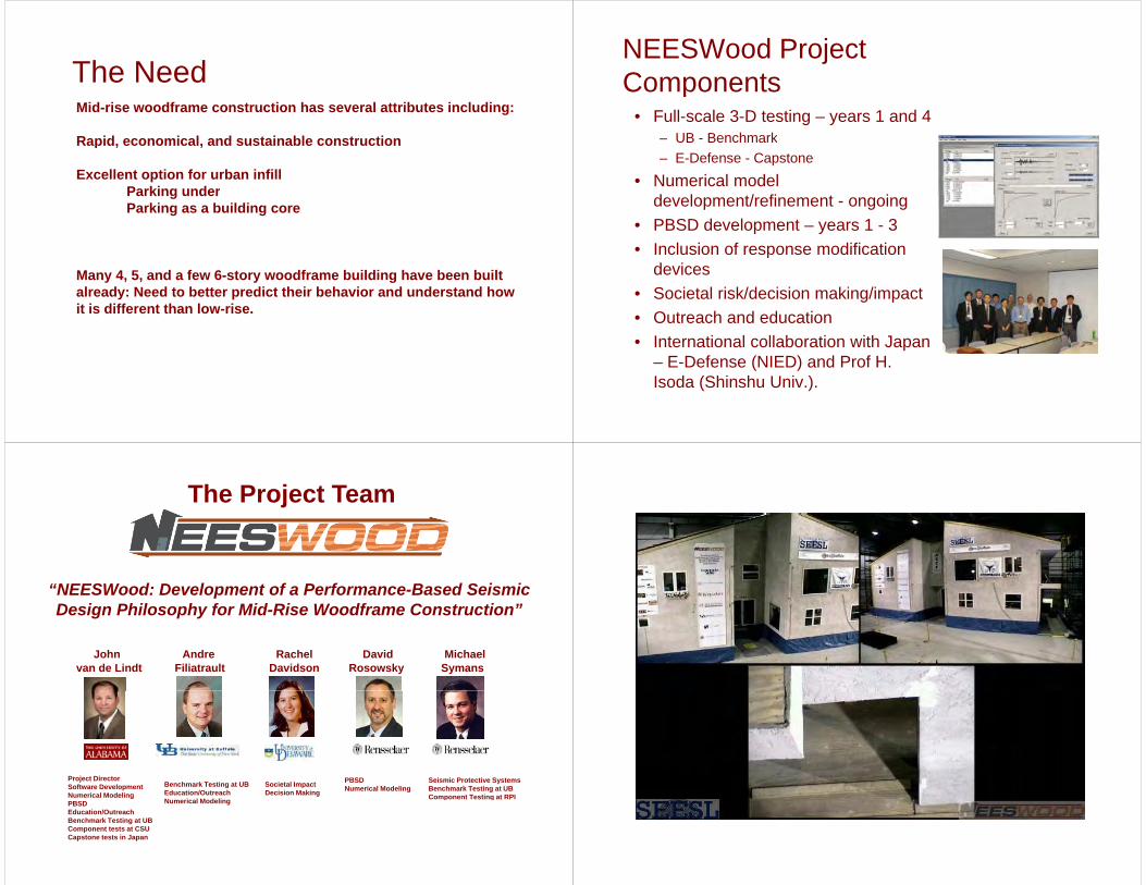
Capstone Test Objectives• Objective 1: To confirm that a representative mid-rise
woodframe structure designed using the NEESWood g gPBSD philosophy satisfies the performance objectives, as pre-defined during the design process. These performance objectives seek to limit damage and losses
hil t ti lif f twhile protecting life safety.
• Objective 2: Provide a general understanding of the b h i f id i df t t i il tbehavior of a mid-rise woodframe structure similar to those currently in place in the Western U.S.
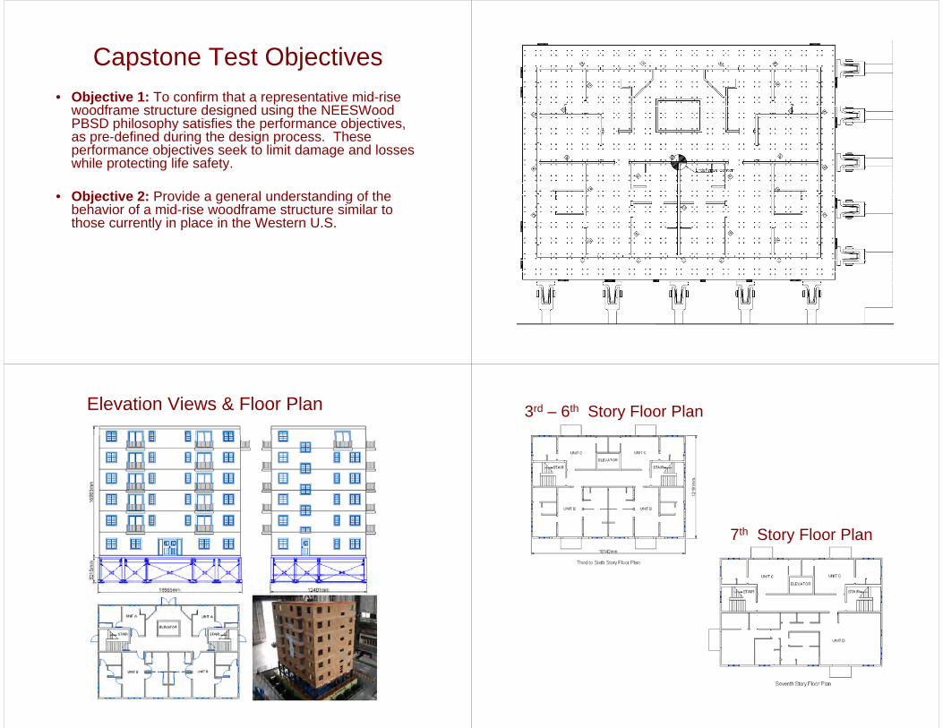
Elevation Views & Floor Plan 3rd – 6th Story Floor Plan
7th Story Floor Plan

Seismic Intensity Levels for DesignL l 1 E h k i i h i 50% h f b iLevel 1: Earthquake intensity having a 50% chance of beingexceeded in 50 years. This corresponds to a 72 year returnperiod.
Level 2: Earthquake intensity having a 10% chance of beingexceeded in 50 years. This corresponds to a 475 year returnperiod Corresponds approximately to the Design-Basisperiod. Corresponds approximately to the Design BasisEarthquake (DBE).
Level 3: Earthquake intensity having a 2% chance of beingq y g gexceeded in 50 years. This corresponds to a 2500 yearreturn period. Corresponds to the Maximum CredibleEarthquake (MCE).
Level 4: Optional Near Fault: Un-scaled near fault groundmotions. This is an optional seismic hazard for use depending
th l ti f b ildi ith t t th f lt d/ thon the location of a building with respect to the fault and/or theowner’s desired performance expectation.
Performance ExpectationsPerformance Expectations
Corresponding Peak Inter-story
Drift (%)
Wood Framing and OSB/Plywood Sheathing
Gypsum Wall Board (GWB)
Mi S litti d ki f Sli ht ki f GWBLevel A 0.1 – 1.0%
Minor Splitting and cracking of sill plates (some propagation)Slight sheathing nail withdraw
Slight cracking of GWBDiagonal propagation from door/window openingsPartial screw withdrawCracking at ceiling-to-wall g ginterface
Level B 1.0 - 2.0% Permanent differential movement of adjacent panelsCorner sheathing nail pulloutC ki / litti f ill/t
Crushing at corners of GWBCracking of GWB taped/mud joints
Cracking/splitting of sill/top plates
Level C 2.0 - 4.0% Splitting of sill plates equal to anchor bolt diameterCracking of studs above
Separation of GWB corners in ceilingBuckling of GWB at openingsg
anchor boltsPossible failure of anchor bolts
g p g
Level D 4.0 - 7.0% Severe damage across edge il li ti f
Large pieces separated from f inail lines, separation of
sheathingVertical posts upliftedFailure of anchor bolts
framingEntire joints separated and dislodged
Design Objectives / Drift Expectations:
P f S i i Performance ExpectationsPerformance Level
Seismic Hazard
e o a ce pectat o sInter‐story Drift Limit
Non‐exceedanceProbability
Level 1 50%/50yr 1% 50%L l 2 10%/50 2% 50%Level 2 10%/50yr 2% 50%Level 3 2%/50yr 4% 80%Level 4 Near‐Fault 7% 50%
Seismic Hazard LevelDesign Limit State for Inter-story Drift:
Level 3 Example
Drift Limit4%
Seismic Hazard Level(2%/50yr) SMS=1.5g, SM1 = 0.9g
lim( | )NE tP H NE Target NE Probability80%
Requirement“Capacity”Non RequirementNon-exceedance(NE) Probability
E-Defense

E-Defense
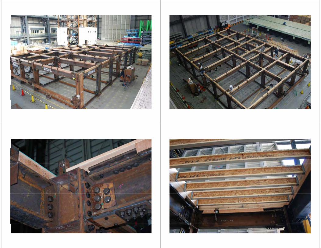


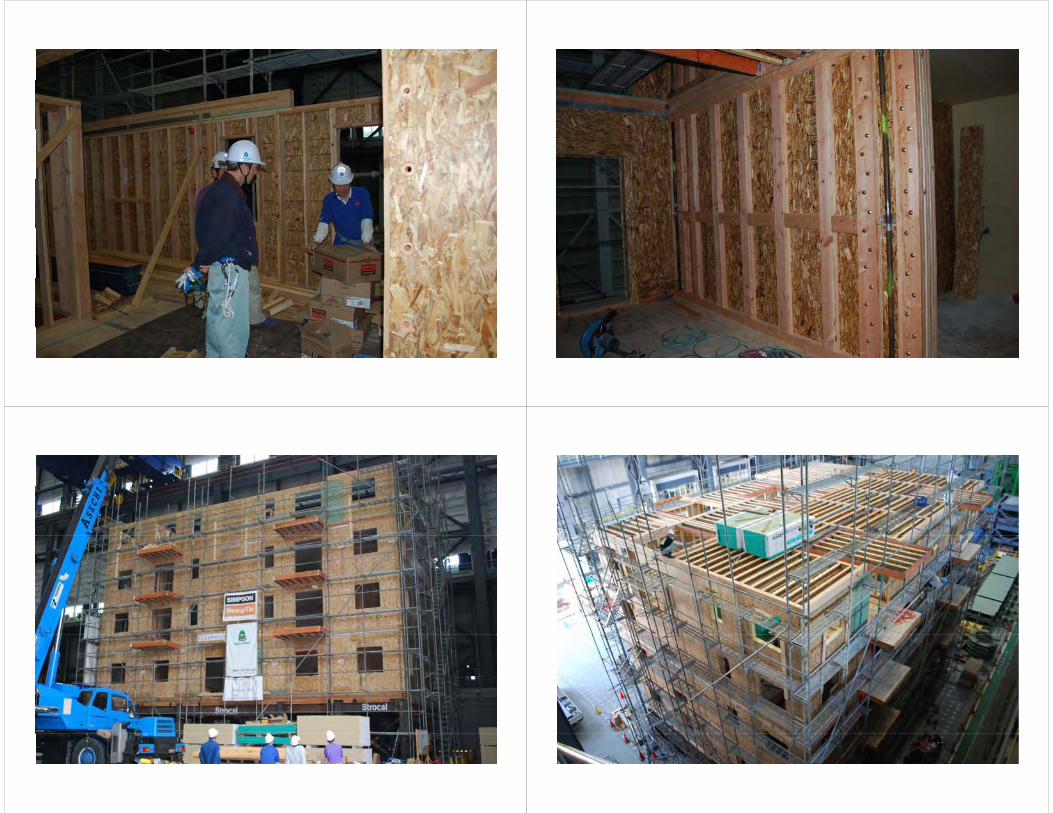


Move Onto Table Construction…
M t L ti T N b
InstrumentationMeasurement Location Type NumberAbsolute acceleration Each Floor 3D-acceleration 38Diagonal shear wall drift Selected shear walls String Potentiometer 33Out of plane diaphragm deformation Third floor diaphragm String Potentiometer 13Shear wall end stud uplift Selected shear walls String Potentiometer 8ATS hold-down strain Selected shear walls Strain Gage 78Absolute displacement Building exterior 3D Optical tracking 50Absolute displacement Building exterior 3D Optical tracking 50
Instrumented allShear walls onLeft side of 1stLeft side of 1Story
Three selectedW ll i t t dWalls instrumentedAll the way to topstory.
Shake Table Test Program

Level 3 movie (Optical tracking)Level 3 movie (Optical tracking)Seismic Level 3 – Long Direction
Seismic Level 3 – From above 2500 year shake – Inside the top floor

Averaged Time History Response: Roof LevelResponse: Roof Level
Averaged Time History Response: Selected resultsResponse: Selected results
Average global hysteresis Optical Tracking

Selected Damage Results Selected Damage Results
Selected Damage Results Selected Damage Results

Conclusions– Light-frame wood buildings can be
constructed six stories tall and perform well in a major earthquake i e 2500 yearwell in a major earthquake, i.e. 2500 year event.
– Designing for a certain level of performance using PBSD is possible and thus, to the extent one test can, validates , ,the design approach developed within NEESWood.
NEESWood AcknowledgementsThe material presented in this presentation is based upon work supported by theNational Science Foundation under Grant No. CMMI-0529903 (NEES Research) andCMMI-0402490 (NEES Operations). Any opinions, findings, and conclusions or( p ) y p , g ,recommendations expressed in this material are those of the author(s) and do notnecessarily reflect the views of the National Science Foundation. The authors aregrateful to the overall NEESWood project team made up of David V. Rosowsky,Andre Filiatrault, Rachel A. Davidson, and Michael D. Symans., , y
Thank you to NSF REU’s Doug Allen and Kathryn Pfrefzschner, researchers Hiro Isoda, Chikahiro Minowa, IzumiNakamura, Chikahiro Minowa, and Mikio Koshihara at the University of Tokyo. Two graduate students, KazakiTachibana and Tomoya Okazaki, contributed to the construction and instrumentation of the test specimen. Thankyou also to Tim Ellis of Simpson Strong Tie Co. and David Clyne of Maui Homes USA. Technical collaboratorsyou also to Tim Ellis of Simpson Strong Tie Co. and David Clyne of Maui Homes USA. Technical collaboratorsbeyond the authors affiliation included the U.S. Forest Product Laboratory, FP Innovations-Forintek Division, MauiHomes U.S.A, and Structural Solutions Inc Financial and in-kind product and personal donations were provided bySimpson Strong Tie, Maui Homes, B.C. Ministry of Housing and Social Development, Stanley Bostitch, StrocalInc., Structural Solutions Inc., Louisiana Pacific Corp., Natural Resources Canada, Forestry InnovationInvestment, APA-The Engineered Wood Association, American Forest and Paper Association, Howdy, Ainsworth,Calvert Glulam, the 2 x 4 Association of Japan, and Mr Jagadish Vengali with IPIRTI. In addition, thank you to thefollowing contributors of products and technical assistance: APA-The Engineered Wood Association, B&LWholesale Supply, Buffalo Plastering, Erie Community College, Gambale USA, DCI Engineers, Hartland Buildersof New York Inc., Georgia Pacific, MiTek Industries, Inc., National Gypsum, NGC Testing Services, Niagara Truss& Pallet LLC, National Overhead Door, Inc., Ridg-U-Rak , Taylor Devices Inc., Kelly Cobeen, , J. Daniel Dolan,Kevin Cheung Borjen Yeh Philip Line Rakesh Gupta Ioannis P Christovasilis Hongyan Li Jayesh ShindeKevin Cheung, Borjen Yeh, Philip Line, Rakesh Gupta, Ioannis P. Christovasilis, Hongyan Li, Jayesh Shinde,Assawin Wanitkorkul, Damon Reigles, James Foreman, James Lucas, Charles Ekiert, David Keller, AndreiReinhorn, Thomas Albrechcinski , Mark Pitman, Christopher Budden, Duane Kozlowski, Robert Staniszewski ,Scot Weinreber, Jason Hanley, Goran Josipovic
Top Related