


![[SOFTWARE DESIGN FOR IGVC COMPETITON ]](https://static.fdocuments.us/doc/165x107/61dab469fc8c63207126e873/software-design-for-igvc-competiton-.jpg)


Languages
Pages
Legal


I certify that the engineering design present in this vehicle is significant and equivalent to work that would satisfy
the requirements of a senior design or graduate project course. – Dr. Ka C. Cheok
Oakland University Presents:

Contents 1 Introduction .................................................................................................................. 1
2 Project Management ..................................................................................................... 1
2.1 Design Strategy ..................................................................................................... 1
2.2 Team Organization ................................................................................................ 1
3 Innovations ................................................................................................................... 2
4 Mechanical System ....................................................................................................... 3
4.1 Chassis Design ...................................................................................................... 3 4.2 Drive Train ............................................................................................................ 3
5 Electrical, Computing and Sensing System .................................................................. 4
5.1 Power Distribution ................................................................................................ 4 5.2 Sensor Array .......................................................................................................... 4
5.3 Hardware Architecture .......................................................................................... 5 5.4 Custom PCB for dsPIC Processors ....................................................................... 6 5.5 Manual Control and Wireless E-Stop.................................................................... 6
5.6 Battery Life ........................................................................................................... 6
6 Software Strategy ......................................................................................................... 7
6.1 Search-Based Path Planning.................................................................................. 7 6.2 Kalman Filter Based Sensor Fusion ...................................................................... 9 6.3 Autonomous Challenge ......................................................................................... 9
6.3.1 Lane Detection .............................................................................................. 10
6.3.2 Goal Point Selection ...................................................................................... 10
6.4 Navigation Challenge .......................................................................................... 11
6.5 Accuracy of Arrival at Waypoints ...................................................................... 11 6.6 JAUS Challenge .................................................................................................. 11
7 Predicted Performance ................................................................................................ 12
7.1 Speed ................................................................................................................... 12
7.2 Ramp Climbing Ability ....................................................................................... 12
8 Cost Breakdown of Components ................................................................................ 13
9 Conclusion .................................................................................................................. 13
Acknowledgements ........................................................................................................... 13

1
Figure 1: Beast 2010
1 Introduction
This year, Oakland University is participating in IGVC with the UGV “Beast.” Beast is a
re-design of X-Man from the 2008 competition. Beast is a light-weight, powerful and energy
efficient mobile platform, designed for ease of maintenance and maneuverability. The team has
high expectations for this year‟s competition, with newly developed artificial intelligence and
improved electronic hardware.
2 Project Management
2.1 Design Strategy
Using experiences gained in past IGVC competitions, as
well as addressing the issues with the previous design, shown in
Figure 2, it was decided to create a lighter, simpler robot for the
2010 competition. The result is Beast,
shown in Figure 1.
To design Beast, the entire team
met on a weekly basis to report
progress, plan the next steps of the
design, and to specify tasks and their
completion deadlines. Each subsystem
had its own champion in charge of it.
Each member would prepare progress reports to keep the rest of the
team updated on the status of their design at each meeting. The
team leader's role was to run the weekly meetings, organize and
manage the team's efforts, and guide the work of the sub-teams
where possible.
2.2 Team Organization
An organization chart of the team outlining the contribution of each of the team members
is shown in Figure 3. All of the team members volunteered their free time to work on Beast, and
contributed a total of approximately 1500 man-hours.
Figure 2: X-Man 2008

2
Figure 3: Team organization chart
3 Innovations
Search-Based Path Planning – Instead of approaching path planning from a completely
control systems point of view as in the past, cost function minimization and fuzzy logic
techniques are used to greatly improve the artificial intelligence.
Rear-View Lidar – Using a Lidar in the back of the vehicle allows for extra visibility of
the robot‟s surroundings, and provides opportunity for better path planning, especially in
the Navigation Challenge.
Custom PCB Electronics – The dsPIC microcontrollers running the drive control
algorithms and interfacing to the wireless remote are mounted on a custom PCB that
provide them with proper power, external oscillators and easy access to the pins.
Team Leader
Micho Radovnikovich
High-Level Software
Micho Radovnikovich
Electronics
Steve Grzebyk
Low-Level
Software
Pavan Vempaty
Mechanical
Design
Kirk McGuire
Frame Design
Scott Marginet Drive Control
Naveen Chilukoti
Vision
Lincoln Lorenz
Matt Bruer
JAUS
Kevin Hallenbeck Path Planning
Micho Radovnikovich

3
4 Mechanical System
4.1 Chassis Design
Beast's chassis is based on Oakland's 2008 IGVC
entry X-Man, but is completely re-designed. While keeping
the original electric wheelchair motors and core structure, as
well as some of the changes from X-Man, the rest of the
frame was modified to make the vehicle much lighter and
simpler. The new chassis design was created around the
requirements set forth in the early design phase, and to
accommodate the desired placement of the hardware
components. Figure 4 shows the base frame from which the
new chassis is derived.
The old frame was much too heavy, with most of the body made out of steel and lots of
unnecessary material. The camera shaft and its base alone weighed almost 40 pounds in the
effort to make it rigid. On Beast, the body is replaced by Plexiglas, and the interior structure is
simplified dramatically, with a compartment for batteries, a
vertically mounted panel for the electronics, and space for the
laptop and other components. It has a fiberglass camera shaft with
tubular aluminum rods in a pyramid-type structure to support it.
The complete chassis is shown in Figure 5.
4.2 Drive Train
The drive train on Beast is the only component of the
original wheelchair that remains unchanged. The drive train
consists of two 24 volt brushed DC motors, which have built-in
32:1 gearboxes. The team retrofitted the motors with optical
encoders to provide feedback measurement to the drive control
program.
Figure 4: Beast’s base frame
Figure 5: Beast's complete
chassis

4
5 Electrical, Computing and Sensing System
5.1 Power Distribution
Beast's power is sourced from four 12
volt, 19 Ah sealed lead acid batteries. They are
arranged with two sets of two batteries in
parallel, which are then put in series with each
other. This 24 volt source is fused, and then fed
directly to the motor controllers. The 24 volt
source is also regulated down to 12 and 5 volts
to power the rest of the components on the
robot. A conventional turn-to-release e-stop
button controls power to the robot‟s systems using a normally closed switch.
To recharge the batteries, two 12 volt chargers are connected to ports on the side of the
chassis, with each one independently charging one of the parallel sets of batteries. Using two
normally open switches controlled by the e-stop button, the batteries are automatically isolated
from the rest of the vehicle‟s circuitry and connected appropriately to the charging ports when
the e-stop is engaged. The power distribution and battery charging circuit are illustrated in
Figure 6.
5.2 Sensor Array
To accurately determine its own pose and perceive the obstacles in its surroundings,
Beast is outfitted with the following sensors:
Hokuyo Lidar: A Hokuyo URG-04LX is used to detect objects to the rear of the
vehicle.
SICK Lidar: A SICK LMS200 Lidar unit is used to detect objects in front of the
vehicle.
Camera: An IDS µEyeLE camera is used to detect lane lines and other
objects of interest.
GPS Receiver: Beast uses a uBlox AEK-4P GPS receiver. The receiver and its
antenna are very small and cheap, but the readings require filtering
with data from other sensors to reliably approach the GPS targets.
Figure 6: Power distribution and battery
charging circuit

5
Digital Compass: A Honeywell HMR3200 digital compass is used to help filter the
readings from the GPS receiver by providing another measurement
of the vehicle‟s heading.
Wheel Encoder: A US Digital E3 encoder is mounted to each of Beast‟s motors to
provide feedback for the drive control algorithm. The readings are
also used to estimate the velocity of the robot, which is another
measurement in the GPS filter.
5.3 Hardware Architecture
The architecture of the computing and sensing hardware is shown in Figure 7. The drive
control software is implemented on a Microchip 30F4011 dsPIC processor. It reads speed
commands via RS-232, measures the pulses from the wheel encoders, and applies PI control
using the encoder readings for feedback. Interface to the wireless remote control is done on a
30F2012 dsPIC processor. All of the high level software like path planning, vision and JAUS
are done on a laptop.
Figure 7: Architecture of Beast’s hardware components
30F2012
dsPIC
µEyeLE
Camera
AEK-4P
GPS
URG-04LX
Lidar
LMS200
Lidar
HMR3200
Compass
Dell Latitude 2100
Laptop
30F4011
dsPIC
US Digital E3
Encoders
DX5E
Radio
Victor 884
H-Bridges

6
5.4 Custom PCB for dsPIC Processors
To reliably provide the dsPIC processors with proper power and high-quality external
oscillators, while also not taking up large amounts of space, a custom PCB board was designed
and fabricated. The board has sockets to hold both the 30F4011 and the 30F2012, and projects
all the I/O pins to headers which can be easily accessed. To allow easy replacement of
components in the case of damage, all the capacitors, resistors, LED and voltage regulator have
sockets as well. The board was fabricated from ExpressPCBTM
, using CAD software. A picture
of the actual PCB and the CAD schematic sent to ExpressPCB are shown in Figure 8.
Figure 8: Custom PCB and its CAD schematic
5.5 Manual Control and Wireless E-Stop
Manual control of Beast is achieved using a Spektrum DX5E radio controller for RC
airplanes. The receiver outputs RC signals whose pulse widths vary according to the joystick
positions on the controller. Because of this, it is very easy to measure the inputs from the
joysticks using the input capture ports on a dsPIC processor and generate appropriate vehicle
speed commands. These speed commands are then sent to the drive control dsPIC.
The wireless e-stop is also implemented using the DX5E, which has a dedicated channel
normally used to deploy the landing gear of an RC airplane. The channel outputs two discrete
pulse widths, and when the pulse width corresponding to the stop state of the switch is detected,
the drive control dsPIC immediately disables PWM output to the motors to stop the vehicle.
5.6 Battery Life
Table 1 shows approximations for the amount of power that each hardware component
being powered from the main batteries consumes. Based on these estimates, it is estimated that
Beast can drive at full power for about 1.2 hours before requiring a recharge in worst case.

7
Using a more realistic estimate of 6 amps for the two motors on average, it is approximated that
Beast lasts about 5 hours. Assuming the batteries are almost completely discharged, the
maximum amount of time it would take to recharge Beast at a 10 amp rate is around 4.5 hours.
While testing Beast, these estimates were found to be quite accurate.
The laptop computer runs off its own power, and also powers the camera and GPS
receiver. Experimentation has shown that while running the software algorithms and powering
the external USB devices, the laptop battery lasts around 4 hours.
Table 1: Power Consumption Estimates
Component Max Current (A) Max Power (W)
SICK LMS200 0.83 20
Hokuyo URG-04LX 0.5 6
Honeywell HMR3200 0.0034 0.041
US Digital E3 Encoder 0.34 1.7
Motors 30 720
6 Software Strategy
All of the software algorithms running on the laptop, with the exception of the JAUS
system, are implemented in Matlab/Simulink. This unified development environment allows for
easy integration of the several different algorithms, and makes debugging the overall system
simpler.
6.1 Search-Based Path Planning
Beast‟s path planning system uses data from the Lidar sensors and camera and applies a
simple search algorithm to find its way to the goal. For each of the 360 degrees around it, the
robot computes a „cost‟ for traveling in that direction. The cost function is computed based on
how clear the surroundings are and how much progress can be made toward to the goal.
Progress toward the goal is quantified according to (1):
𝑓𝐷 𝑖 = 𝜆1𝑟𝑖 + 𝜆2𝑑𝑖 (1)
where 𝑓𝐷 𝑖 is the „distance function‟ in a given direction 𝑖, 𝑟𝑖 is the distance to the nearest
obstacle in the direction 𝑖, 𝑑𝑖 is the distance from this obstacle to the goal, and 𝜆1, 𝜆2 are
constants. The geometry of this is shown in Figure 9. By adjusting the values of 𝜆1 and 𝜆2, the
robot places different emphasis on making aggressive movements toward the goal.

8
The total cost function is then constructed based on (1) as well as a measure of how clear
the surroundings are, as shown in (2):
𝐶 𝑖 = 𝑓𝐷𝛼 𝑖 ∙ 𝑓
𝑂−𝛽(𝑖) (2)
where 𝐶 𝑖 is the total cost to go in direction 𝑖, 𝑓𝑂 𝑖 is proportional to how far an obstacle is
from the robot in that direction, and 𝛼, 𝛽 are constants. The
contribution of 𝑓𝑂 lowers the cost when the obstacle is far away,
thus encouraging the robot to explore open areas. By properly
tuning the constants in (1) and (2), as the robot approaches its
goal but it sees an obstacle in its path, it is naturally attracted to
the edge of the obstacle, which allows for very efficient
traversal of it.
To avoid situations where the robot reaches a cost
function well and gets stuck, as well as to encourage it to keep
moving the same general direction, a two-step disallowing
region is defined where the robot just came from. This is
shown in Figure 10. Since the algorithm naturally goes to the
edges of obstacles, it tends to get too close and slow down
dramatically. Therefore, another preventive measure is taken,
where it makes a reflective movement away from it once it gets
within a certain threshold of an obstacle.
The search algorithm was simulated in Matlab, where a test map was drawn to simulate
obstacles, and a program was written to generate simulated Lidar scans depending on the current
position and heading of the robot. The location
of the goal point and the Lidar data are inputted
to the search algorithm, and the robot tries to
navigate itself to the goal. An example of this
simulation is shown in Figure 11.
Attracted to
Obstacle
Edges
𝑟𝑖
𝑑𝑖
Move 1
Move 2
Combined
Disallowed
Region
Figure 10: Disallow short-
term backtracking
Figure 9: Search-based
path planning

9
6.2 Kalman Filter Based Sensor Fusion
Since the AEK-4P GPS receiver lacks the accuracy to reliably get to the waypoints, a
Kalman filter is used to fuse readings from the compass, wheel encoders, and GPS to provide a
much more accurate estimate of the vehicle‟s location.
6.3 Autonomous Challenge
For the Autonomous Challenge, the search-based path planning system is used, but
adapted to accommodate the different task. The core decision-making algorithm remains the
same, but the system also integrates lane line information, while also periodically updating the
goal point.
Simulated Lidar Scan
Cost Function Plot
Min
imu
m C
ost
Disallowed
Next Goal Point
Figure 11: Example of search-based path planning simulation
10
6.3.1 Lane Detection
In the Autonomous Challenge, anything that is not green grass is something that should
be detected and avoided. Based on this assumption, a median thresholding technique is used to
extract objects of interest from the grass background of an incoming image from the robot‟s
camera. After performing the median thresholding, the locations of the objects of interest are
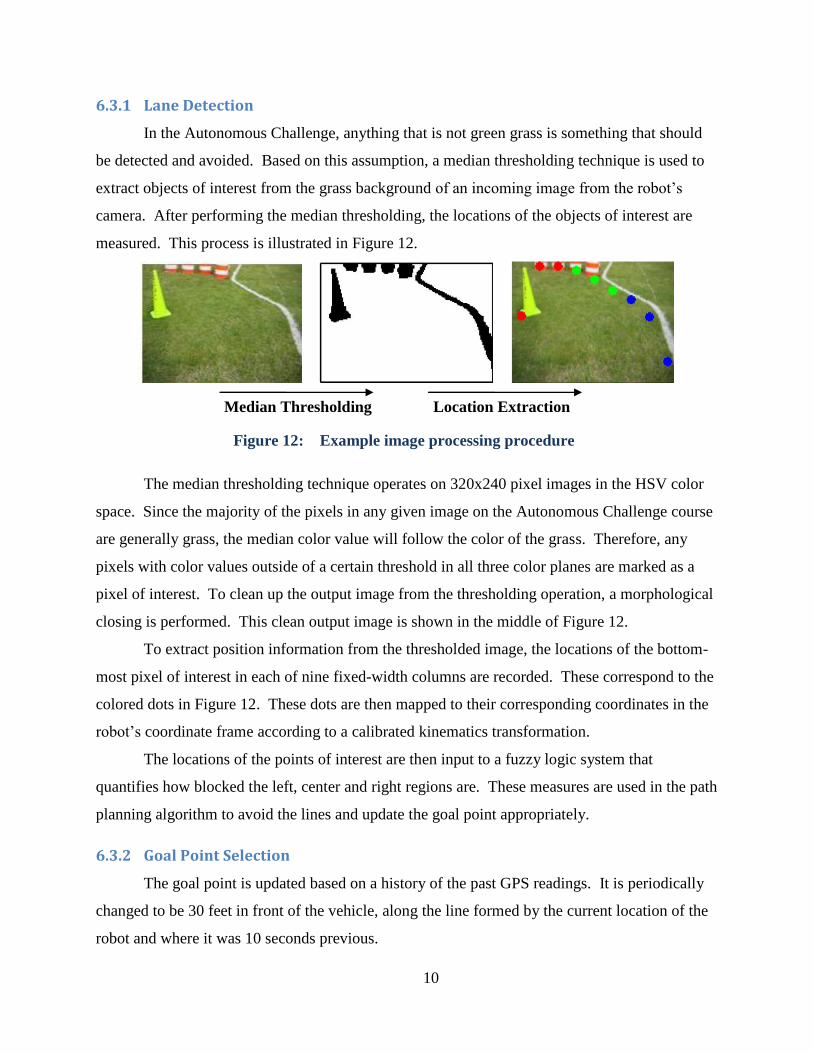
measured. This process is illustrated in Figure 12.
The median thresholding technique operates on 320x240 pixel images in the HSV color
space. Since the majority of the pixels in any given image on the Autonomous Challenge course
are generally grass, the median color value will follow the color of the grass. Therefore, any
pixels with color values outside of a certain threshold in all three color planes are marked as a
pixel of interest. To clean up the output image from the thresholding operation, a morphological
closing is performed. This clean output image is shown in the middle of Figure 12.
To extract position information from the thresholded image, the locations of the bottom-
most pixel of interest in each of nine fixed-width columns are recorded. These correspond to the
colored dots in Figure 12. These dots are then mapped to their corresponding coordinates in the
robot‟s coordinate frame according to a calibrated kinematics transformation.
The locations of the points of interest are then input to a fuzzy logic system that
quantifies how blocked the left, center and right regions are. These measures are used in the path
planning algorithm to avoid the lines and update the goal point appropriately.
6.3.2 Goal Point Selection
The goal point is updated based on a history of the past GPS readings. It is periodically
changed to be 30 feet in front of the vehicle, along the line formed by the current location of the
robot and where it was 10 seconds previous.
Figure 12: Example image processing procedure
Median Thresholding Location Extraction

11
The lane detection system outputs the angle of the
lines that it sees, and this measurement of the angle is used to
adjust the goal point as illustrated in Figure 13.
6.4 Navigation Challenge
The search-based path planning system is very well
suited for the Navigation Challenge because the goal points
are fixed. The task is then to pick a sequence of waypoints
and directly input them as the goals in the path planning
system.
6.5 Accuracy of Arrival at Waypoints
From experimentation, it was observed that the raw,
unprocessed position readings from the AEK-4P receiver had
a variance of around ±2 meters, which would be unreliable for
arriving at the GPS waypoints. However, with the Kalman filter
fusing the GPS readings with the wheel encoders and compass, the variance was brought down
to about ±1.1 meters. Waypoint navigation tests using the output from the Kalman filter were
found to yield much better results than similar tests using the raw GPS data.
6.6 JAUS Challenge
For the JAUS Challenge, it was decided to utilize the OpenJAUS project, an open source
implementation of the JAUS protocol. The OpenJAUS functions are implemented in C, and are
responsible for reading incoming JAUS messages, running state machines to govern the response
and reaction to these messages, and generating properly formatted JAUS messages to transmit.
In order to relay information to and from the robot‟s Matlab-based systems, loopback TCP is
used. A diagram of the JAUS system is shown in Figure 14.
Original
Goal
Point
Adjusted
Goal Point
Figure 13: Goal
point selection

12
7 Predicted Performance
7.1 Speed
While spinning at full speed, the wheels were measured to be rotating at 148 RPM. With
13 inch wheels, this corresponds to a forward speed of 5.72 mph, which exceeds the
requirements for the competition. Therefore, the drive control program on the dsPIC processor
limits the output it can apply to the motors such that the fastest they can rotate is 125 RPM. At
125 RPM, the speed of the robot is 4.83 mph.
7.2 Ramp Climbing Ability
To determine if Beast would be able to climb the ramps on the Autonomous Challenge
course, some simple estimates and calculations were made. The wet coefficient of friction
between Beast‟s tires and the plywood was determined experimentally to be 0.282. With the
weight of the robot approximately 150 pounds and assuming nominal torque of each motor being
applied, this resulted in a maximum constant-speed climb angle of 15.7 degrees. Also, based on
Output Message
Generator
State Machine
COP
Input Message
Interpreter
Beast’s Systems
OpenJAUS
C Implementation
Matlab
Software
Algorithms
Loopback TCP
Figure 14: Diagram of the JAUS system implementation

13
these estimates, Beast should be able to climb the approximately 8.5 degree ramps while
accelerating at 1.37 m/s2, without slipping.
8 Cost Breakdown of Components
Table 2: Cost Breakdown of the Development of Beast
Item Quantity Price Extended Price Cost to Team
Ublox GPS Unit 1 $198 $198 $198
Optical Wheel Encoder 2 $52 $104 $104
SICK Lidar 1 $4,000 $4,000 $0
Hokuyo Lidar 1 $2,375 $2,375 $2,375
Digital Compass 1 $175 $175 $175
Machine Vision Camera 1 $380 $380 $380
Camera Lens 1 $75 $75 $75
Dell Laptop 1 $560 $560 $560
Electric Wheelchair 1 $1,100 $1,100 $0
12 Volt, 19 Ah Battery 4 $75 $300 $300
PCB Fabrication N/A $60 $60 $60
Motor Controller 2 $115 $230 $230
Frame Materials N/A $400 $400 $0
Wire, Cabling and Connectors N/A $200 $200 $200
IC's and Circuit Components N/A $100 $100 $100
Total: $10,257 $4,757
9 Conclusion
Beast has proven to be very rugged, efficient and reliable, performing well while driving
on any kind of terrain. The new artificial intelligence design shows promising results, and the
Oakland University team has great confidence going into this year‟s competition.
Acknowledgements
The Oakland University IGVC team would like to express gratitude to the School of
Engineering and Computer Science for providing the funding and lab space without which,
participation in IGVC would not be possible. Special thanks also goes to our advisor, Professor
Ka C. Cheok, from whom we continually learn valuable techniques that not only help us in
IGVC, but prepare us for the future.
Top Related