


Languages
Pages
Legal

New!
Patent pending
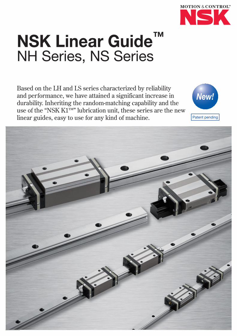
NSK Linear Guide™
NH Series, NS Series
Based on the LH and LS series characterized by reliability and performance, we have attained a significant increase in durability. Inheriting the random-matching capability and the use of the “NSK K1™” lubrication unit, these series are the new linear guides, easy to use for any kind of machine.
1 22
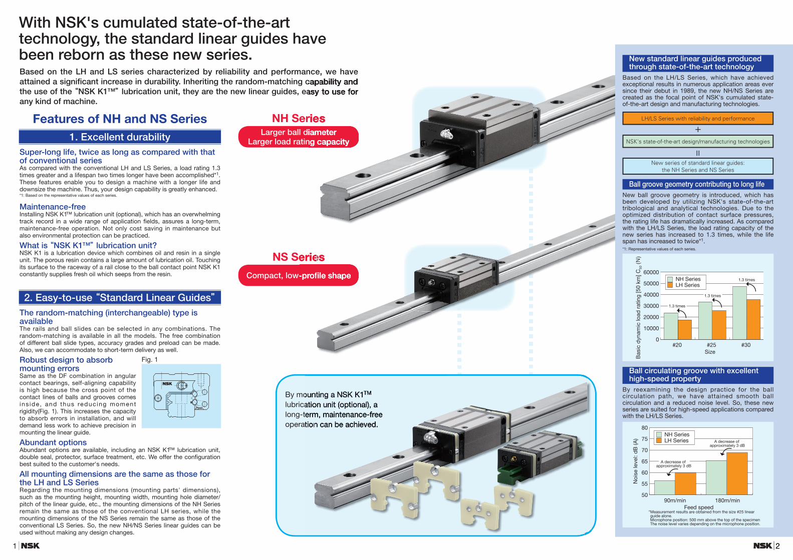
NH SeriesLarger ball diameter
Larger load rating capacity
NS Series
Compact, low-profi le shape
By mounting a NSK K1TM lubrication unit (optional), a long-term, maintenance-free operation can be achieved.
Features of NH and NS Series 1. Excellent durability
Super-long life, twice as long as compared with that of conventional seriesAs compared with the conventional LH and LS Series, a load rating 1.3 times greater and a lifespan two times longer have been accomplished*1. These features enable you to design a machine with a longer life and downsize the machine. Thus, your design capability is greatly enhanced.*1: Based on the representative values of each series.
Maintenance-freeInstalling NSK K1™ lubrication unit (optional), which has an overwhelming track record in a wide range of application fi elds, assures a long-term, maintenance-free operation. Not only cost saving in maintenance but also environmental protection can be practiced.
What is “NSK K1™” lubrication unit?NSK K1 is a lubrication device which combines oil and resin in a single unit. The porous resin contains a large amount of lubrication oil. Touching its surface to the raceway of a rail close to the ball contact point NSK K1 constantly supplies fresh oil which seeps from the resin.
2. Easy-to-use “Standard Linear Guides”The random-matching (interchangeable) type is availableThe rails and ball slides can be selected in any combinations. The random-matching is available in all the models. The free combination of different ball slide types, accuracy grades and preload can be made. Also, we can accommodate to short-term delivery as well.
Robust design to absorb mounting errors Same as the DF combination in angular contact bearings, self-aligning capability is high because the cross point of the contact lines of balls and grooves comes ins ide, and thus reduc ing moment rigidity(Fig. 1). This increases the capacity to absorb errors in installation, and will demand less work to achieve precision in mounting the linear guide.
Abundant optionsAbundant options are available, including an NSK K1™ lubrication unit, double seal, protector, surface treatment, etc. We offer the confi guration best suited to the customer's needs.
All mounting dimensions are the same as those for the LH and LS SeriesRegarding the mounting dimensions (mounting parts' dimensions), such as the mounting height, mounting width, mounting hole diameter/pitch of the linear guide, etc., the mounting dimensions of the NH Series remain the same as those of the conventional LH series, while the mounting dimensions of the NS Series remain the same as those of the conventional LS Series. So, the new NH/NS Series linear guides can be used without making any design changes.
Fig. 1
With NSK's cumulated state-of-the-art technology, the standard linear guides have been reborn as these new series.Based on the LH and LS series characterized by reliability and performance, we have attained a signifi cant increase in durability. Inheriting the random-matching capability and the use of the “NSK K1™” lubrication unit, they are the new linear guides, easy to use for any kind of machine.
Based on the LH and LS series characterized by reliability and performance, we have
NH SeriesLarger ball diameter
Larger load rating capacity
Based on the LH and LS series characterized by reliability and performance, we have attained a signifi cant increase in durability. Inheriting the random-matching capability and the use of the “NSK K1™” lubrication unit, they are the new linear guides, easy to use for
By mounting a NSK K1lubrication unit (optional), a long-term, maintenance-free operation can be achieved.
By mounting a NSK K1TM
lubrication unit (optional), a long-term, maintenance-free operation can be achieved.
NS Series
Compact, low-profi le shape
NS Series
Compact, low-profi le shape
New standard linear guides produced through state-of-the-art technology
Based on the LH/LS Series, which have achieved exceptional results in numerous application areas ever since their debut in 1989, the new NH/NS Series are created as the focal point of NSK's cumulated state-of-the-art design and manufacturing technologies.
LH/LS Series with reliability and performance
+NSK's state-of-the-art design/manufacturing technologies
New series of standard linear guides: the NH Series and NS Series
=
Ball groove geometry contributing to long lifeNew ball groove geometry is introduced, which has been developed by utilizing NSK's state-of-the-art tribological and analytical technologies. Due to the optimized distribution of contact surface pressures, the rating life has dramatically increased. As compared with the LH/LS Series, the load rating capacity of the new series has increased to 1.3 times, while the life span has increased to twice*1.*1: Representative values of each series.
0
10000
20000
30000
40000
50000
60000
#20 #25 #30
NH SeriesLH Series
Size
Bas
ic d
ynam
ic lo
ad r
atin
g [5
0 km
] C50
(N)
1.3 times
1.3 times
1.3 times
Ball circulating groove with excellent high-speed property
By reexamining the design practice for the ball circulation path, we have attained smooth ball circulation and a reduced noise level. So, these new series are suited for high-speed applications compared with the LH/LS Series.
* Measurement results are obtained from the size #25 linear guide alone.
Microphone position: 500 mm above the top of the specimen The noise level varies depending on the microphone position.
50
55
60
65
70
75
80
90m/min 180m/min
NH SeriesLH Series
Feed speed
Noi
se le
vel:
dB
(A)
A decrease of approximately 3 dB
A decrease of approximately 3 dB

3
NSK Linear Guide™ NH Series, NS Series
4
1. Ball Slide Shape⨋⨋ Two types of ball slides are available: One is of the square type with tapped holes, and the other is of the mounting flange type.⨋⨋ Regarding the square type, a compact, low-profile model is also available.⨋⨋ On the mounting holes of the flange type, the tapped part is used to fix the ball slide from the top surface, while the minor diameter can be used as a bolt hole for mounting from the bottom. This enables mounting from either direction, top or bottom.⨋⨋ The ball slide length is available in three lengths: standard high-load, long super-high load or short medium-load. The ball slide length you can use differs, depending on the type. Please refer to the dimension table.
Fig. 2 Ball slide shape
Ball slideshape
Shape/installation methodType (Upper row: Rating; Lower row: Ball slide length)
High-load type Super-high-load type Medium-load typeStandard Long Short
ANBN
AN高荷重形
AL・AN BL・BN
超高荷重形
GL・HL・GM EL・FL・EM
L1 L1
L1L1
BN高荷重形
AL・AN BL・BN
超高荷重形
GL・HL・GM EL・FL・EM
L1 L1
L1L1
ALBLCL
AL高荷重形
AL・AN BL・BN
超高荷重形
GL・HL・GM EL・FL・EM
L1 L1
L1L1
BL高荷重形
AL・AN BL・BN
超高荷重形
GL・HL・GM EL・FL・EM
L1 L1
L1L1
CL
L1
L1 L1
L1
高荷重形
AL CL
中荷重形
JL・KL・JMEL・FL・EM
EMGMJM
EM
高荷重形
AL・AN BL・BN
超高荷重形
GL・HL・GM EL・FL・EM
L1 L1
L1L1GM
高荷重形
AL・AN BL・BN
超高荷重形
GL・HL・GM EL・FL・EM
L1 L1
L1L1JM
L1
L1 L1
L1
高荷重形
AL CL
中荷重形
JL・KL・JMEL・FL・EM
2. Maximum Rail Length⨋⨋ Table 1 shows the limitations of rail length (maximum length).⨋⨋ Depending on the required accuracy grade, the available maximum rail length might be shorter than the one shown in Table 1.
Table 1 Length limitations of rails Unit: mm
Series Size
Material 15 20 25 30 35 45 55 65
NHSpecial high carbon steel 2 980 3 960 3 960 4 000 4 000 3 990 3 960 3 900
Stainless steel 1 800 3 500 3 500 3 500
NSSpecial high carbon steel 2 920 3 960 3 960 4 000 4 000
Stainless steel 1 800 3 500 3 500 3 500 3 500Note: Rails can be butted if user requirement exceeds the rail length shown in the table. Please consult NSK.
3. Accuracy⨋⨋ The setting of the accuracy grade differs depending on whether the required type is of the preloaded assembly or the random-matching type.⨋⨋ For the preloaded assembly, different accuracy grades are available: Ultra precision P3, Super precision P4, High precision P5, Precision P6, and Normal PN grades.⨋⨋ While the random-matching type has High precision PH and Normal PC grade.
Table 2 Tolerance of preloaded assembly Unit: μm
Accuracy grade Characteristics
Ultra precisionP3
Super precisionP4
High precisionP5
Precision gradeP6
Normal gradePN
Mounting height HVariation of H(All ball slides on a set of rails)
±83
±105
±207
±4015
±8025
Mounting width W2 or W3Variation of W2 or W3(All ball slides on reference rail)
±103
±157
±2510
±5020
±10030
Running parallelism of surface C to surface ARunning parallelism of surface D to surface B Refer to Fig. 3 and Table 4.
Table 3 Tolerance of random-matching type Unit: μm
Accuracy grade Characteristics
High precision gradePH
Normal gradePC
Model No. NH15,20,25,30,35NS15,20,25,30,35 NH45,55,65 NH15,20,25,30,35
NS15,20,25,30,35 NH45,55,65
Mounting height H ±20 ±30 ±20 ±30Variation of mounting height H 15 20 15 20Mounting width W2 or W3 ±30 ±35 ±30 ±35Variation of mounting width W2 or W3 20 20 25 30
Running parallelism of surface C to surface ARunning parallelism of surface D to surface B Refer to Fig. 3 and Table 4.
Note: Variation in the random-matching products means the variation among the values taken at the same position on the same rail.
Table 4 Running parallelism of ball slide Unit: μm
Preload assembly Random-matching typeRail length
(mm)Ultra precision
P3Super precision
P4High precision
P5Precision grade
P6Normal grade
PNHigh precision
PHNormal grade
PC
Over - 50 or less 2 2 2 4 5 2 550 - 80 2 2 3 4 5 3 5
80 - 125 2 2 3 4 5 3 5125 - 200 2 2 3.5 5 6 3.5 6200 - 250 2 2.5 4.5 6 7.5 4.5 7.5250 - 315 2 2.5 5 6.5 8.5 5 8.5315 - 400 2 3 5.5 7 9.5 5.5 9.5400 - 500 2 3 6 7.5 11 6 11500 - 630 2 3.5 6.5 8.5 12 6.5 12630 - 800 2 4 7 9.5 13 7 13
800 - 1 000 2.5 4.5 7.5 10 15 7.5 151 000 - 1 250 3 5 8.5 12 16 8.5 161 250 - 1 600 3.5 5.5 9.5 13 17 9.5 171 600 - 2 000 4 6.5 11 14 19 11 192 000 - 2 500 4.5 7.5 12 16 21 12 212 500 - 3 150 5.5 8.5 13 18 23 13 233 150 - 4 000 6 9.5 14 19 25 14 25
Fig. 3 Specifications of accuracy
C
A
D
B
KL markReference railof preloadedassembly type only
Groove markfor datum surface
H
W2(Marked on eitherlateral or bottomsurface for a rail)
Mounting width W2
C
A
D
B
KL markReference railof preloadedassembly type only
H
W3
Groove markfor datum surface
Groove markfor datum surface
(Marked on eitherlateral or bottomsurface for a rail)
Mounting width W3
Specifications
5
NSK Linear Guide™ NH Series, NS Series
6
4. Preload and Rigidity⨋⨋ Preload setting differs between the preloaded assembly and random-matching types.⨋⨋ For the preloaded assembly, Medium preload Z3, Slight preload Z1 and Fine clearance Z0 are available.⨋⨋ For the random-matching type, Medium preload ZH, Slight preload ZZ and Fine clearance ZT are available.⨋⨋ Possible combinations between the accuracy and preload grades are shown in Table 9.
5. Basic Load Rating and Rating LifeThe basic load rating used for expressing the load capacity of the linear guide is determined by ISO standards (ISO 14728-1, 14728-2). The load rating applied to NSK Linear Guides complies with the ISO standards.The basic dynamic load rating is the non-fluctuating load which acts on the center of the ball slide from above, and under which the rating fatigue life of 100 km or 50 km is expressed. When load F is only applied to the ball slide in the up/down direction, its rating fatigue life, L can be calculated using the following equation, where C100 means a basic dynamic load rating for 100 km rating fatigue life and C50 means a basic dynamic load rating for 50 km rating fatigue life respectively. The basic static load rating is the static load which generates a contact stress of 4 200 MPa at the center of the contact area between the rolling element subjected to the maximum stress and the raceway surface. In this most heavily stressed contact area, the sum of the permanent deformation of the rolling element and that of the raceway is nearly 0.0001 times the rolling element’s diameter.The basic load rating values are written in the dimension table. In NH and NS series, the contact angle is set at 50 degrees, and thus increasing load carrying capacity in vertical direction. Each basic load rating in the down, up and lateral load direction is shown at Table 11.
Table 5 Preload and rigidity of preloaded assembly (1) NH Series
Model No.Preload (N)
Rigidity (N/μm)Vertical direction Lateral direction
Slight preload Z1
Medium preloadZ3
Slight preload Z1
Medium preloadZ3
Slight preload Z1
Medium preloadZ3
NH15 AN,⨋EM 78 490 137 226 98 186NH20 AN,⨋EM 147 835 186 335 137 245NH25 AL,⨋AN,⨋EM 196 1 270 206 380 147 284NH30 AL,⨋AN 245 1 570 216 400 157 294NH30 EM 294 1 770 265 480 186 355NH35 AL,⨋AN,⨋EM 390 2 350 305 560 216 390NH45 AL,⨋AN,⨋EM 635 3 900 400 745 284 540NH55 AL,⨋AN,⨋EM 980 5 900 490 910 345 645NH65 AN,⨋EM 1 470 8 900 580 1 070 400 755NH15 BN,⨋GM 98 685 196 345 137 284NH20 BN,⨋GM 196 1 080 265 480 196 355NH25 BL,⨋BN,⨋GM 245 1 570 294 560 216 400NH30 BL,⨋BN,⨋GM 390 2 260 360 665 265 480NH35 BL,⨋BN,⨋GM 490 2 940 430 795 305 570NH45 BL,⨋BN,⨋GM 785 4 800 520 960 370 695NH55 BL,⨋BN,⨋GM 1 180 7 050 635 1 170 440 835NH65 BN,⨋GM 1 860 11 300 805 1 480 550 1 040
Note: Clearance for Fine clearance Z0 is 0 to 3 μm, Therefore, preload is zero. However, Z0 of PN grade is 0 to 15 μm.
Table 7 Preload and rigidity of preloaded assembly (2) NS Series
Model No.Preload (N)
Rigidity (N/μm)Vertical direction Lateral direction
Slight preload Z1
Medium preloadZ3
Slight preload Z1
Medium preloadZ3
Slight preload Z1
Medium preloadZ3
NS15 AL,⨋EM 69 390 127 226 88 167NS20 AL,⨋EM 88 540 147 284 108 206NS25 AL,⨋EM 147 880 206 370 147 275NS30 AL,⨋EM 245 1 370 255 460 186 345NS35 AL,⨋EM 345 1 960 305 550 216 400NS15 CL,⨋JM 49 294 78 147 59 108NS20 CL,⨋JM 69 390 108 186 78 137NS25 CL,⨋JM 98 635 127 235 88 177NS30 CL,⨋JM 147 980 147 275 108 206NS35 CL,⨋JM 245 1 370 186 335 137 245
Note: Clearance for Fine clearance Z0 is 0 to 3 μm, Therefore, preload is zero. However, Z0 of PN grade is 0 to 15 μm.
Table 9 Combinations of accuracy and preload
Accuracy grade
Ultra precision
Super precision
High precision
Precision grade
Normal grade
High precision
Normal grade
Without NSK K1 lubrication unit P3 P4 P5 P6 PN PH PCWith NSK K1 lubrication unit K3 K4 K5 K6 KN KH KC
With NSK K1 for food and medical equipment F3 F4 F5 F6 FN FH FC
Pre
load
Fine clearanceZ0 » » » » » — —
Slight preloadZ1 » » » » » — —
Medium preloadZ3 » » » » — — —
Random-matching type withfine clearance ZT — — — — — — »
Random-matching type withslight preload ZZ — — — — — » »
Random-matching type withmedium preload ZH — — — — — » »
Table 6 Clearance and preload of random-matching type (1) NH Series Unit: μm
Model No. Fine clearance ZT
Slight preload ZZ
Medium preloadZH
NH15 –4 ~ 15 –4 ~ 0 –3 ~ –7NH20
–5 ~ 15
–5 ~ 0 –3 ~ –8NH25 –5 ~ 0 –4 ~ –9NH30 –7 ~ 0 –5 ~ –12NH35 –7 ~ 0 –5 ~ –12NH45 –7 ~ 0 –7 ~ –14NH55 –9 ~ 0 –9 ~ –18NH65 –9 ~ 0 –10 ~ –19
Note: Minus sign denotes a value is an amount of preload (elastic deformation of balls).
Table 8 Clearance and preload of random-matching type (2) NS Series Unit: μm
Model No. Fine clearance ZT
Slight preload ZZ
Medium preloadZH
NS15 –4 ~ 15 –4 ~ 0 –3 ~ –7NS20 –4 ~ 15 –4 ~ 0 –3 ~ –7NS25 –5 ~ 15 –5 ~ 0 –4 ~ –9NS30 –5 ~ 15 –5 ~ 0 –4 ~ –9NS35 –5 ~ 15 –6 ~ 0 –4 ~ –10
Note: Minus sign denotes a value is an amount of preload (elastic deformation of balls).
The loads applied to the linear guide (i.e., ball slide loads) range from loads in the up/down or right/left direction to moment loads. Sometimes, more than one type of load is applied simultaneously or the volume and direction of the load may vary.Varying loads cannot be used for the life calculation of the linear guide as they are. Therefore, it is necessary to use a hypothetical constant load applied to the ball slide, which would generate a fatigue life equivalent to the actual fatigue life. This is called the dynamic equivalent load. To calculate the dynamic equivalent load, use the loads provided in Table 12.
Table 10 Load factor fwImpact/vibration Load factor
No external impact/vibration 1.0 ~ 1.5There is impact/vibration from outside. 1.5 ~ 2.0
There is significant impact/vibration. 2.0 ~ 3.0
L = 100 × C100
fw·F
3
or L = 50 × C50
fw·F
3
[km]
⨋⨋ Please note that the equation used here for calculating the product life is different from the one used for the linear guides for which rollers are used as rolling elements.⨋⨋ The load factor is expressed as “fw”. Select the best-suited load factor, referring to the values given in Table 10, according to the potential vibration or impact loads in the machine onto which the linear guide is to be mounted.
M rFr
Fs
MyMp
Fig. 4 Load directions
Table 12 Loads in the arrangement of linear guides
Pattern Arrangement of linear guide
Loads necessary to calculate dynamic equivalent load
Dynamic equivalent loadLoad Moment load
Up/down(vertical)
Right/left(lateral)
Rolling Pitching Yawing
1 Fr Fs Mr Mp My Fr =Fr
Fse =Fs · tanαFre =εr · Mr
Fpe =εp · Mp
Fye =εy · My
α : Contact angle (=50°)
Dynamic equivalent coefficientsεr : Rolling directionεp : Pitching directionεy : Yawing direction
2 Fr Fs Mr
3 Fr Fs Mp My
4 Fr Fs
The formula is determined by the relationship of loads in terms of volume. A full dynamic equivalent load can be easily obtained by using each coefficient. After obtaining the dynamic equivalent load of the necessary load direction from Table 13, use the formulas below to calculate full dynamic equivalent loads.· When Fr is the largest load: Fe = Fr + 0.5Fse + 0.5Fre + 0.5Fpe + 0.5Fye· When Fse is the largest load: Fe = 0.5Fr + Fse + 0.5Fre + 0.5Fpe + 0.5Fye· When Fre is the largest load: Fe = 0.5Fr + 0.5Fse + Fre + 0.5Fpe + 0.5Fye· When Fpe is the largest load: Fe = 0.5Fr + 0.5Fse + 0.5Fre + Fpe + 0.5Fye· When Fye is the largest load: Fe = 0.5Fr + 0.5Fse + 0.5Fre + 0.5Fpe + FyeFor the values of each dynamic equivalent load in the formulas above, disregard load directions and take the absolute value.
Table 13 Dynamic equivalent coefficients
ModelDynamic equivalent coefficients (1/m)εr εp εy
NH15AN, EM 188 111 132NH15BN, GM 188 72 86NH20AN, EM 142 81 97NH20BN, GM 142 57 68
NH25AL, AN, EM 123 68 81NH25BL, BN, GM 123 51 61
NH30AL, AN 98 70 83NH30EM 98 58 69
NH30BL, BN, GM 98 44 52NH35AL, AN, EM 78 51 61NH35BL, BN, GM 78 36 43NH45AL, AN, EM 60 38 45NH45BL, BN, GM 60 30 36NH55AL, AN, EM 51 31 37NH55BL, BN, GM 51 25 30
NH65AN, EM 43 27 32NH65BN, GM 43 20 24NS15AL, EM 177 116 138NS15CL, JM 177 174 208NS20AL, EM 127 94 112NS20CL, JM 127 136 162NS25AL, EM 111 70 83NS25CL, JM 111 108 129NS30AL, EM 94 63 75NS30CL, JM 94 102 121NS35AL, EM 76 54 64NS35CL, JM 76 87 104
Table 11 Basic load rating by load directionDirection
Load ratingDownward Upward Lateral
Basic dynamic load rating C C 0.84CBasic static load rating C0 0.78C0 0.65C0

7
NSK Linear Guide™ NH Series, NS Series
88
6. Dust-proof parts and Lubrication accessories(1) Standard specification⨋⨋ Standard specification can be readily used as they have a dust protection means for normal conditions. As the standard equipment, the ball slides have an end seal on both ends, and bottom seals at the bottom.⨋⨋ Dust-proof parts are available, as shown in Table 14. Select the best-suited one according to the operation environment.
(2) Mounting position of the lubrication accessories⨋⨋ The standard position of grease fittings is the end face of ball slide. We mount them on a side of end cap for an option. (Fig. 6).⨋⨋ Please consult NSK for installation of grease or tube fittings to the ball slide body or side of end cap.
(3) NSK K1TM Lubrication unit Table 15 shows the dimensions of the linear guides equipped with the NSK K1 lubrication unit.
7. Rust Prevention(1) Stainless steelStainless steel material can be selected for the parts made of carbon steel. The models which can be made with stainless steel are NH15-30 and NS15-35. However, the high precision (PH) grade and the medium preload (ZH) type of the random-matching type can not be made from stainless steel.
(2) Surface treatmentRegard ing sur face t rea tment , NSK recommends low temperature chrome plating or fluoride low temperature chrome plating.Please consult NSK for other surface treatment.
8. Installation(1) Permissible values of mounting errorMounting errors may result in harmful effects, such as shortened operating life, deteriorated motion accuracy and/or friction variation. Using those mounting errors shown in Figures 8 and 9 as representative errors, Tables 17 and 18 show the mounting tolerances.
9. Maximum allowable speedAn indication of the standard maximum allowable speed aiming at 10,000km operation with linear guide under normal conditions is shown in Table 19. However, the maximum allowable speed can be affected by accuracy of installation, operating temperature, external load, etc.If the operation is made exceeding the permissible distance and speed, please contact NSK.
10. Handling Precautions(1) Beating a slide or hitting it against an object may cause damage.(2) Operating temperature should be less than 80℃ . If exceeding this temperature, the plastic parts might be
damaged.(3) If using NSK K1, maximum temperature in use : 50℃ (momentary maximum temperature in use: 80℃ ). Do
not leave NSK K1 lubrication unit in organic solvent, white kerosene such as hexane, thinner which removes oil, and rust prevention oil which contains white kerosene.
(4) Regarding the handling of random-matching products. a) Slides of random-matching type are assembled on a provisional rail (an inserting tool) when it is delivered. b) When a slide is installed to the rail, make certain to use a provisional rail. c) Do not remove slides from the provisional rail, except installation to the rail.
Table 14 Optional dust-proof parts
Name Purpose
NSK K1lubrication unit Made of oil impregnated resin. Enhances lubricating functions.
Double seal It combines two end seals for enhancing sealing function.Protector Protect the end seal from hot and hard contaminants.
Rail cap Prevents foreign matters, such as swarf generated in cutting operation from clogging the rail-mounting holes.
Inner seal Installed inside a slide, and prevents foreign matters from entering the rolling contact surface.Bellows Covers the linear guide.
Note: Inner seals can be selected for NH20-65 and NS20-35.
Bottom seal(under seal)
End seal(side seal)
Fig. 5
Ball slide body
End capStandard position
Optional position
Fig. 6 Mounting position of lubrication accessories
V1V2V2
NV1
L
NSK K1Protective cover
End seal
Fig. 7
Table 16 Material/surface treatment codeCode Description
C Special high carbon steel (NSK standard)K Stainless steelD Special high carbon steel with surface treatmentH Stainless steel with surface treatmentZ Other, special
Table 15 Unit: mm
Model No.Standard ball slide
length
Ball slide length installed with two
NSK K1 L
Per NSK K1 thickness V1
Protective cover
thickness V2
Protruding area of the grease
fitting N
NH15AN, EM 55 65.6
4.5 0.8 (5)BN, GM 74 84.6
NH20AN, EM 69.8 80.4
4.5 0.8 (14)BN, GM 91.8 102.4
NH25AL, AN, EM 79 90.6
5 0.8 (14)BL, BN, GM 107 118.6
NH30
AL, AN 85.6 97.6
5 1 (14)EM 98.6 110.6
BL, BN, GM 124.6 136.6
NH35AL, AN, EM 109 122
5.5 1 (14)BL, BN, GM 143 156
NH45AL, AN, EM 139 154
6.5 1 (15)BL, BN, GM 171 186
NH55AL, AN, EM 163 178
6.5 1 (15)BL, BN, GM 201 216
NH65AN, EM 193 211
8 1 (16)BN, GM 253 271
NS15AL, EM 56.8 66.4
4 0.8 (5)CL, JM 40.4 50
NS20AL, EM 65.2 75.8
4.5 0.8 (14)CL, JM 47.2 57.8
NS25AL, EM 81.6 92.2
4.5 0.8 (14)CL, JM 59.6 70.2
NS30AL, EM 96.4 108.4
5 1 (14)CL, JM 67.4 79.4
NS35AL, EM 108 121
5.5 1 (14)CL, JM 77 90
Notes: (1) NSK K1 for food and medical equipments are available for NH15-35 and NS15-35.(2) Ball slide length equipped with NSK K1 = (Standard ball slide length) + (Thickness of NSK K1, V1 x Number
of NSK K1) + (Thickness of the protective cover, V2 x 2)
e1
Fig. 8
e2
500
Fig. 9
Table 17 Unit: μm
Value Preload Model No.NH15 NH20 NH25 NH30 NH35 NH45 NH55 NH65
Permissible values of parallelism in two rails e1
Z0, ZT 22 30 40 45 55 65 80 110Z1, ZZ 18 20 25 30 35 45 55 70Z3, ZH 13 15 20 25 30 40 45 60
Permissible values of parallelism(height) in two rails e2
Z0, ZT 375μm/500mmZ1, ZZ, Z3, ZH 330μm/500mm
Table 20 Maximum allowable speed Unit: m/min
SizeSeries 15 20 25 30 35 45 55 65
NH 300 200 150NS 300 — —
Table 18 Unit: μm
Value Preload Model No.NS15 NS20 NS25 NS30 NS35
Permissible values of parallelism in two rails e1
Z0, ZT 20 22 30 35 40Z1, ZZ 15 17 20 25 30Z3, ZH 12 15 15 20 25
Permissible values of parallelism(height) in two rails e2
Z0, ZT 375μm/500mmZ1, ZZ, Z3, ZH 330μm/500mm
(2) Shoulder height and corner radius of the mounting surfaceWhen horizontally fixing a rail or ball slide by pushing it to the shoulder (the riser portion of the mounting surface) of the bed or table, refer to the shoulder height and corner radius specified in Fig. 10 and 11 and Table 18 as well.
Shoulder height of the mounting surface and corner radius r
ra
H'
ra
H''rb
rb
Fig. 11 Shoulder for the ball slide datum surface
Fig. 10 Shoulder for the rail datum surface
Table 19 Unit: mm
Model No. Corner radius (maximum) Shoulder heightra rb H' H"
NH15 0.5 0.5 4 4NH20 0.5 0.5 4.5 5NH25 0.5 0.5 5 5NH30 0.5 0.5 6 6NH35 0.5 0.5 6 6NH45 0.7 0.7 8 8NH55 0.7 0.7 10 10NH65 1 1 11 11NS15 0.5 0.5 4 4NS20 0.5 0.5 4.5 5NS25 0.5 0.5 5 5NS30 0.5 0.5 6 6NS35 0.5 0.5 6 6

9
NSK Linear Guide™ NH Series, NS Series
1010
11. DimensionsNH-AN (High-load type/standard, square type)NH-BN (Super-high-load type/long, square type)
NH 30 1200 AN C 2 -]] P5 3 ——— —— ———— ——— — — ———— ——— —Series name
Size
Rail length (mm)
Ball slide shape code (refer to Fig. 2 on page 3)
Material/surface treatment code (refer to Table 16 on page 7)C: Special high carbon steel (NSK standard); K: Stainless steel
Preload code (refer to Table 9 on page 5)0:Z0, 1:Z1, 3:Z3, T:ZT, Z:ZZ, H:ZH
Accuracy code (refer to Table 9 on page 5)
Design serial numberAdded to the reference number
Number of ball slides per rail
N A H 30 AN S Z -K ———— —— ——— — — ——Random-matching ball slide series codeNAH: NH Series random-matching ball slide
Size
Ball slide shape code (refer to Fig. 2 on page 3)
Option code -K: Equipped with NSK K1 -F: Fluoride low temperature chrome plating + AS2 grease -F50: Fluoride low temperature chrome plating + LG2 grease
Preload codeNo code: Fine clearance, Z: Slight preload, H: Medium preload
Material code No code: Special high carbon steel (NSK standard), S: Stainless steel
N1H 30 1200 L C N -]] PC Z ———— —— ————— — — — ———— ——— —Random-matching rail series codeN1H: NH Series random-matching rail
Size
Rail length (mm)
Rail shape code: LL: Standard
Material/surface treatment code (refer to Table 16 on page 7)
Preload code T: Fine clearance, Z: Slight preload (common rail for slight or medium preload) (refer to Table 9 on page 5)
Accuracy code PH: High precision grade random-matching type PC: Normal grade random-matching type
Design serial numberAdded to the reference number
Butting rail specification*N: Non-butting; L: Butting specification
(1) Reference number for assembly
*Please consult with NSK for butting rail specification.
(2) Reference number for random-matching type
Ball slide
Rail
Unit: mm
Model No.
Assembly Ball slide Rail Basic load rating WeightHeight
H E W2
Width
W
Length
L
Mounting hole
L1 K T
Grease fitting Width
W1
Height
H1
Pitch
F
Mountingbolt holed×D×h
G
(reference)
Max. lengthL0max
( ) for stainless
2)Dynamic Static Static moment (N·m) Ball slide(kg)
Rail
(kg/m)B J M×Pitch×l Hole size T1 N[50km]C50(N)
[100km]C100(N)
C0(N)
MRO MPO MYO(One slide) (Two slides) (One slide) (Two slides)
NH15ANNH15BN 28 4.6 9.5 34 55
74 26 26 M4×0.7×6 3958 23.4 8 φ3 8.5 3.3 15 15 60 4.5×7.5×5.3 20 2 980
(1 800)14 20018 100
11 30014 400
20 70032 000
108166
94.5216
5751 150
79.5181
480965
0.180.26 1.6
NH20ANNH20BN 30 5 12 44 69.8
91.8 32 3650 M5×0.8×6 50
72 25 12 M6×0.75 5 11 20 18 60 6×9.5×8.5 20 3 960(3 500)
23 70030 000
18 80024 000
32 50050 500
219340
185420
1 1402 230
155355
9551 870
0.330.48 2.6
NH25ANNH25BN 40 7 12.5 48 79
107 35 3550 M6×1×9 58
86 33 12 M6×0.75 10 11 23 22 60 7×11×9 20 3 960(3 500)
33 50045 500
26 80036 500
46 00071 000
360555
320725
1 8403 700
267610
1 5403 100
0.550.82 3.6
NH30ANNH30BN 45 9 16 60 85.6
124.6 40 4060 M8×1.25×10 59
98 36 14 M6×0.75 10 11 28 26 80 9×14×12 20 4 000(3 500)
41 00061 000
32 50048 500
51 50091 500
490870
3501 030
2 2905 600
292865
1 9204 700
0.771.3 5.2
NH35ANNH35BN 55 9.5 18 70 109
143 50 5072 M8×1.25×12 80
114 45.5 15 M6×0.75 15 11 34 29 80 9×14×12 20 4 000 62 50081 000
49 50064 500
80 500117 000
9501 380
7551 530
4 5008 350
6301 280
3 8007 000
1.52.1 7.2
NH45ANNH45BN 70 14 20.5 86 139
171 60 6080 M10×1.5×17 105
137 56 17 Rc1/8 20 13 45 38 105 14×20×17 22.5 3 990 107 000131 000
84 500104 000
140 000187 000
2 1402 860
1 7403 000
9 75015 600
1 4602 520
8 15013 100
3.03.9 12.3
NH55ANNH55BN 80 15 23.5 100 163
201 75 7595 M12×1.75×18 126
164 65 18 Rc1/8 21 13 53 44 120 16×23×20 30 3 960 158 000193 000
125 000153 000
198 000264 000
3 6004 850
3 0005 150
16 30026 300
2 5104 350
13 70022 100
4.76.1 16.9
NH65ANNH65BN 90 16 31.5 126 193
253 76 70120 M16×2×20 147
207 74 23 Rc1/8 19 13 63 53 150 18×26×22 35 3 900 239 000310 000
190 000246 000
281 000410 000
6 1508 950
4 95010 100
27 90051 500
4 1508 450
23 40043 500
7.710.8 24.3
Notes: 1) External appearance of stainless steel ball slides differs from those of carbon steel ball slides. 2) The basic load rating comply with the ISO standard. (ISO14728-1 and ISO14728-2) C50: the basic dynamic load rating for 50 km rating fatigue life, C100: the basic dynamic load rating for 100 km rating fatigue life
L1
T1
(N ) L
J
L1
T1
(N ) L
J
h
φD
H1
φd
F
G
L0
n×F (G)
MPO
MRO
T
KH
E
W2 W1
W
B
4-M×l
MYO
Side view of AN type
Side view of BN type
Front view of AN and BN types
φD
H1
L0
n×F
F
(G) GW1
φd
h
4-M×l
B
W
W1
T
K
E
H
MRO
MYO
W2
T1
L
MPO
J
L1
(N )
AN形
T1
L
J
L1
(N )
BN形
AN and BN types AN type BN type
Assembly (Preloaded assembly, random-matching type)
Ball slide of random-matching type
Rail of random-matching type
Click!Speedy™ NSK Linear Guide Quick Delivery System uses a new numbering system. For details, please refer to the Click!Speedy general catalog CAT. No. E3191.

11
NSK Linear Guide™ NH Series, NS Series
12
φD
H1
L0
n×F
F
(G) GW1
φd
h
JL1L
jD
jdF
G (G)n×FL0
(N )
T1
hH1
MPO
12
NH-AL (High-load type/standard, square low-profile type)NH-BL (Super-high-load type/long, square low-profile type)
Unit: mm
Model No.
Assembly Ball slide Rail Basic load rating WeightHeight
H E W2
Width
W
Length
L
Mounting hole
L1 K T
Grease fitting Width
W1
Height
H1
Pitch
F
Mountingbolt holed×D×h
G
(reference)
Max. lengthL0max
( ) for stainless
2)Dynamic Static Static moment (N·m) Ball slide(kg)
Rail
(kg/m)B J M×Pitch×l Hole size T1 N[50km]C50(N)
[100km]C100(N)
C0(N)
MRO MPO MYO(One slide) (Two slides) (One slide) (Two slides)
NH25ALNH25BL 36 7 12.5 48 79
107 35 3550 M6×1×6 58
86 29 12 M6×0.75 6 11 23 22 60 7×11×9 20 3 960(3 500)
33 50045 500
26 80036 500
46 00071 000
360555
320725
1 8403 700
267610
1 5403 100
0.460.69 3.6
NH30ALNH30BL 42 9 16 60 85.6
124.6 40 4060 M8×1.25×8 59
98 33 14 M6×0.75 7 11 28 26 80 9×14×12 20 4 000(3 500)
41 00061 000
32 50048 500
51 50091 500
490870
3501 030
2 2905 600
292865
1 9204 700
0.691.16 5.2
NH35ALNH35BL 48 9.5 18 70 109
143 50 5072 M8×1.25×8 80
114 38.5 15 M6×0.75 8 11 34 29 80 9×14×12 20 4 000 62 50081 000
49 50064 500
80 500117 000
9501 380
7551 530
4 5008 350
6301 280
3 8007 000
1.21.7 7.2
NH45ALNH45BL 60 14 20.5 86 139
171 60 6080 M10×1.5×10 105
137 46 17 Rc1/8 10 13 45 38 105 14×20×17 22.5 3 990 107 000131 000
84 500104 000
140 000187 000
2 1402 860
1 7403 000
9 75015 600
1 4602 520
8 15013 100
2.22.9 12.3
NH55ALNH55BL 70 15 23.5 100 163
201 75 7595 M12×1.75×13 126
164 55 15 Rc1/8 11 13 53 44 120 16×23×20 30 3 960 158 000193 000
125 000153 000
198 000264 000
3 6004 850
3 0005 150
16 30026 300
2 5104 350
13 70022 100
3.74.7 16.9
Notes: 1) External appearance of stainless steel ball slides differs from those of carbon steel ball slides. 2) The basic load rating comply with the ISO standard. (ISO14728-1 and ISO14728-2) C50: the basic dynamic load rating for 50 km rating fatigue life, C100: the basic dynamic load rating for 100 km rating fatigue life
Rail of random-matching type
T1
JL1L(N )
4-M×lBW
W1W2
T
K
E
H
MRO
MYO
4-M×lBW
W2 W1
TK
E
H
MRO
MYO
JL1L(N )
T1
MPO
JL1L
T1
(N )
NH 30 1200 AL C 2 -]] P5 3 ——— —— ———— ——— — — ———— ——— —Series name
Size
Rail length (mm)
Ball slide shape code (refer to Fig. 2 on page 3)
Material/surface treatment code (refer to Table 16 on page 7)C: Special high carbon steel (NSK standard); K: Stainless steel
Preload code (refer to Table 9 on page 5)0:Z0, 1:Z1, 3:Z3, T:ZT, Z:ZZ, H:ZH
Accuracy code (refer to Table 9 on page 5)
Design serial numberAdded to the reference number
Number of ball slides per rail
N A H 30 AL S Z -K ———— —— ——— — — ——Random-matching ball slide series codeNAH: NH Series random-matching ball slide
Size
Ball slide shape code (refer to Fig. 2 on page 3)
Option code -K: Equipped with NSK K1 -F: Fluoride low temperature chrome plating + AS2 grease -F50: Fluoride low temperature chrome plating+ LG2 grease
Preload codeNo code: Fine clearance, Z: Slight preload, H: Medium preload
Material code No code: Special high carbon steel (NSK standard), S: Stainless steel
N1H 30 1200 L C N -]] PC Z ———— —— ————— — — — ———— ——— —Random-matching rail series codeN1H: NH Series random-matching rail
Size
Rail length (mm)
Rail shape code: LL: Standard
Material/surface treatment code (refer to Table 16 on page 7)
Preload code T: Fine clearance, Z: Slight preload (common rail for slight or medium preload) (refer to Table 9 on page 5)
Accuracy code PH: High precision grade random-matching type PC: Normal grade random-matching type
Design serial numberAdded to the reference number
Butting rail specification*N: Non-butting; L: Butting specification
(1) Reference number for assembly
*Please consult with NSK for butting rail specification.
(2) Reference number for random-matching type
Ball slide
Rail
Side view of AL type
Side view of BL type
Front view of AL and BL types
AL and BL types AL type BL type
Assembly (Preloaded assembly, random-matching type)
Ball slide of random-matching type
Click!Speedy™ NSK Linear Guide Quick Delivery System uses a new numbering system. For details, please refer to the Click!Speedy general catalog CAT. No. E3191.

13
NSK Linear Guide™ NH Series, NS Series
1414
NH-EM (High-load type/standard, flange type)NH-GM (Super-high-load type/long, flange type)
Unit: mm
Model No.
Assembly Ball slide Rail Basic load rating WeightHeight
H E W2
Width
W
Length
L
Mounting hole
L1 K T
Grease fitting Width
W1
Height
H1
Pitch
F
Mountingbolt holed×D×h
G
(reference)
Max. lengthL0max
( ) for stainless
3)Dynamic Static Static moment (N·m) Ball slide(kg)
Rail
(kg/m)B J M×Pitch×l Q2 Hole size T1 N[50km]C50(N)
[100km]C100(N)
C0(N)
MRO MPO MYO(One slide) (Two slides) (One slide) (Two slides)
NH15EMNH15GM 24 4.6 16 47 55
74 38 30 M5×0.8×7 4.4 3958 19.4 8 φ3 4.5 3.3 15 15 60 4.5×7.5×5.3 20 2 980
(1 800)14 20018 100
11 30014 400
20 70032 000
108166
94.5216
5751 150
79.5181
480965
0.170.25 1.6
NH20EMNH20GM 30 5 21.5 63 69.8
91.8 53 40 M6×1×9.5 5.3 5072 25 10 M6×0.75 5 11 20 18 60 6×9.5×8.5 20 3 960
(3 500)23 70030 000
18 80024 000
32 50050 500
219340
185420
1 1402 230
155355
9551 870
0.450.65 2.6
NH25EMNH25GM 36 7 23.5 70 79
107 57 45 M8×1.25×10(M8×1.25×11.5) 6.8 58
86 29 11(12) M6×0.75 6 11 23 22 60 7×11×9 20 3 960
(3 500)33 50045 500
26 80036 500
46 00071 000
360555
320725
1 8403 700
267610
1 5403 100
0.630.93 3.6
NH30EMNH30GM 42 9 31 90 98.6
124.6 72 52 M10×1.5×12(M10×1.5×14.5) 8.6 72
98 33 11(15) M6×0.75 7 11 28 26 80 9×14×12 20 4 000
(3 500)47 00061 000
37 50048 500
63 00091 500
600870
5051 030
3 1505 600
425865
2 6504 700
1.21.6 5.2
NH35EMNH35GM 48 9.5 33 100 109
143 82 62 M10×1.5×13 8.6 80114 38.5 12 M6×0.75 8 11 34 29 80 9×14×12 20 4 000 62 500
81 00049 50064 500
80 500117 000
9501 380
7551 530
4 5008 350
6301 280
3 8007 000
1.72.4 7.2
NH45EMNH45GM 60 14 37.5 120 139
171 100 80 M12×1.75×15 10.5 105137 46 13 Rc1/8 10 13 45 38 105 14×20×17 22.5 3 990 107 000
131 00084 500
104 000140 000187 000
2 1402 860
1 7403 000
9 75015 600
1 4602 520
8 15013 100
33.9 12.3
NH55EMNH55GM 70 15 43.5 140 163
201 116 95 M14×2×18 12.5 126164 55 15 Rc1/8 11 13 53 44 120 16×23×20 30 3 960 158 000
193 000125 000153 000
198 000264 000
3 6004 850
3 0005 150
16 30026 300
2 5104 350
13 70022 100
56.5 16.9
NH65EMNH65GM 90 16 53.5 170 193
253 142 110 M16×2×24 14.6 147207 74 23 Rc1/8 19 13 63 53 150 18×26×22 35 3 900 239 000
310 000190 000246 000
281 000410 000
6 1508 950
4 95010 100
27 90051 500
4 1508 450
23 40043 500
1014.1 24.3
Notes: 1) Parenthesized dimensions are for items made of stainless steel. 3) The basic load rating comply with the ISO standard. (ISO14728-1 and ISO14728-2) 2) External appearance of stainless steel ball slides differs from those of carbon steel ball slides. C50: the basic dynamic load rating for 50 km rating fatigue life, C100: the basic dynamic load rating for 100 km rating fatigue life
W2 W1
4-φQ1×
T
KH
E
W
B
MRO
MYO
MYO
B
W
W1
T
K
E
H
MRO
W2
4-M×(φQ 2 pilot drill)
JL1L(N)
T1
JL1L
T1
(N)
MPO
jD
jdF
G n×F (G)
L0
hH1
B
W
W1
T
K
E
H
MRO
MYO
W2
4-M×(φQ 2 pilot drill)
B
W
W1
T
K
E
H
MRO
MYO
W2
4-φQ1×
JL1L
T1
(N)
MPO
JL1L(N)
T1
φD
H1
L0
n×F
F
(G) GW1
φd
h
Rail of random-matching type
NH 30 1200 EM C 2 -]] P5 3 ——— —— ———— ——— — — ———— ——— —Series name
Size
Rail length (mm)
Ball slide shape code (refer to Fig. 2 on page 3)
Material/surface treatment code (refer to Table 16 on page 7)C: Special high carbon steel (NSK standard); K: Stainless steel
Preload code (refer to Table 9 on page 5)0:Z0, 1:Z1, 3:Z3, T:ZT, Z:ZZ, H:ZH
Accuracy code (refer to Table 9 on page 5)
Design serial numberAdded to the reference number
Number of ball slides per rail
N A H 30 EM S Z -K ———— —— ——— — — ——Random-matching ball slide series codeNAH: NH Series random-matching ball slide
Size
Ball slide shape code (refer to Fig. 2 on page 3)
Option code -K: Equipped with NSK K1 -F: Fluoride low temperature chrome plating + AS2 grease -F50: Fluoride low temperature chrome plating + LG2 grease
Preload codeNo code: Fine clearance, Z: Slight preload, H: Medium preload
Material code No code: Special high carbon steel (NSK standard), S: Stainless steel
N1H 30 1200 L C N -]] PC Z ———— —— ————— — — — ———— ——— —Random-matching rail series codeN1H: NH Series random-matching rail
Size
Rail length (mm)
Rail shape code: LL: Standard
Material/surface treatment code (refer to Table 16 on page 7)
Preload code T: Fine clearance, Z: Slight preload (common rail for slight or medium preload) (refer to Table 9 on page 5)
Accuracy code PH: High precision grade random-matching type PC: Normal grade random-matching type
Design serial numberAdded to the reference number
Butting rail specification*N: Non-butting; L: Butting specification
(1) Reference number for assembly
*Please consult with NSK for butting rail specification.
(2) Reference number for random-matching type
Ball slide
Rail
Side view of EM type
Side view of GM type
Front view of EM and GM types
EM and GM types EM type GM type
Assembly (Preloaded assembly, random-matching type)
Ball slide of random-matching type
Click!Speedy™ NSK Linear Guide Quick Delivery System uses a new numbering system. For details, please refer to the Click!Speedy general catalog CAT. No. E3191.

15
NSK Linear Guide™ NH Series, NS Series
1616
NS-CL (Medium-load type/short, square low-profile type)NS-AL (High-load type/standard, square low-profile type)
Unit: mm
Model No.
Assembly Ball slide Rail Basic load rating WeightHeight
H E W2
Width
W
Length
L
Mounting hole
L1 K T
Grease fitting Width
W1
Height
H1
Pitch
F
Mountingbolt holed×D×h
G
(reference)
Max. lengthL0max
( ) for stainless
2)Dynamic Static Static moment (N·m) Ball slide(kg)
Rail
(kg/m)B J M×Pitch×l Hole size T1 N[50km]C50(N)
[100km]C100(N)
C0(N)
MRO MPO MYO(One slide) (Two slides) (One slide) (Two slides)
NS15CLNS15AL 24 4.6 9.5 34 40.4
56.8 26 —26 M4×0.7×6 23.6
40 19.4 10 φ 3 6 3 15 12.5 60 *4.5×7.5×5.33.5×6×4.5 20 2 920
(1 800)7 250
11 2005 7508 850
9 10016 900
45.584.5
24.577
196470
20.564.5
165395
0.140.20 1.4
NS20CLNS20AL 28 6 11 42 47.2
65.2 32 —32 M5×0.8×7 30
48 22 12 M6×0.75 5.5 11 20 15.5 60 6×9.5×8.5 20 3 960(3 500)
10 60015 600
8 40012 400
13 40023 500
91.5160
46.5133
330755
39111
279630
0.190.28 2.3
NS25CLNS25AL 33 7 12.5 48 59.6
81.6 35 —35 M6×1×9 38
60 26 12 M6×0.75 7 11 23 18 60 7×11×9 20 3 960(3 500)
17 70026 100
14 00020 700
20 80036 500
164286
91258
6551 470
76217
5501 230
0.340.51 3.1
NS30CLNS30AL 42 9 16 60 67.4
96.4 40 —40 M8×1.25×12 42
71 33 13 M6×0.75 8 11 28 23 80 7×11×9 20 4 000(3 500)
24 70038 000
19 60030 000
29 60055 000
282520
139435
1 0802 650
116365
9052 220
0.580.85 4.8
NS35CLNS35AL 48 10.5 18 70 77
108 50 —50 M8×1.25×12 49
80 37.5 14 M6×0.75 8.5 11 34 27.5 80 9×14×12 20 4 000(3 500)
34 50052 500
27 30042 000
40 00074 500
465865
220695
1 6704 000
185580
1 4003 350
0.861.3 7.0
Notes: 1) External appearance of stainless steel ball slides differs from those of carbon steel ball slides. *) Standard rail mounting bolt hole for NS15 is specified as hole for M4 (4.5 x 7.5 x 5.3). 2) The basic load rating comply with the ISO standard. (ISO14728-1 and ISO14728-2) Please contact NSK to request a different hole for M3 (3.5 x 6 x 4.5). C50: the basic dynamic load rating for 50 km rating fatigue life, C100: the basic dynamic load rating for 100 km rating fatigue life
W
B
T
KH
E
W2 W1
MYO
MRO
L
L12-M×l
(N)
T1
CL形
4-M×l
L
L1
(N)
T1
hH1
L0
G
F
n×F
φd
φD
J
(G)
Mpo
AL形
B
W
W1
TK
E
H
MRO
MYO
W2
J
T1
L
MPO
L1
(N)
AL形
4-M×l
T1
L
L1
(N)
CL形
2-M×l
φD
H1
L0
n×F
F
(G) G
W1
φd
h
Rail of random-matching type
NS 30 1200 AL C 2 -]] P5 3 ——— —— ———— ——— — — ———— ——— —Series name
Size
Rail length (mm)
Ball slide shape code (refer to Fig. 2 on page 3)
Material/surface treatment code (refer to Table 16 on page 7)C: Special high carbon steel (NSK standard); K: Stainless steel
Preload code (refer to Table 9 on page 5)0:Z0, 1:Z1, 3:Z3, T:ZT, Z:ZZ, H:ZH
Accuracy code (refer to Table 9 on page 5)
Design serial numberAdded to the reference number
Number of ball slides per rail
N A S 30 AL S Z -K ———— —— ——— — — ——Random-matching ball slide series codeNAS: NS Series random-matching ball slide
Size
Ball slide shape code (refer to Fig. 2 on page 3)
Option code -K: Equipped with NSK K1 -F: Fluoride low temperature chrome plating + AS2 grease -F50: Fluoride low temperature chrome plating + LG2 grease
Preload codeNo code: Fine clearance, Z: Slight preload, H: Medium preload
Material code No code: Special high carbon steel (NSK standard), S: Stainless steel
N1S 30 1200 L C N -]] PC Z ———— —— ————— — — — ———— ——— —Random-matching rail series codeN1S: NS Series random-matching rail
Size
Rail length (mm)
Rail shape code: LL: Standard, T: The rail mounting bolt hole M4 for NS15
Material/surface treatment code (refer to Table 16 on page 7)
Preload code T: Fine clearance, Z: Slight preload (common rail for slight or medium preload) (refer to Table 9 on page 5)
Accuracy code PH: High precision grade random-matching type PC: Normal grade random-matching type
Design serial numberAdded to the reference number
Butting rail specification*N: Non-butting; L: Butting specification
(1) Reference number for assembly
*Please consult with NSK for butting rail specification.
(2) Reference number for random-matching type
Ball slide
Rail
Side view of AL type
Side view of CL type
Front view of AL and CL types
AL and CL types AL type CL type
Assembly (Preloaded assembly, random-matching type)
Ball slide of random-matching type
Click!Speedy™ NSK Linear Guide Quick Delivery System uses a new numbering system. For details, please refer to the Click!Speedy general catalog CAT. No. E3191.

17
NSK Linear Guide™ NH Series, NS Series
18
φD
H1
L0
n×F
F
(G) G
W1
φd
h
W
B
W2 W1
H K
E
T
2-M×
T1
L
L14-M×
(N )(N )
T1
L
L1
J
MRO
MYO
MPO
(φQ2 pilot drill)(φQ2 pilot drill)
G
F
n×F (G)
L0
H1
D
d
W
B
W2 W1
H K
E
T
2-M×
T1
L
L1
(φQ2 pilot drill)4-M×
(N )
(N )
T1
L
L1
J
MPOMRO
MYO h
φ
φ
(φQ2 pilot drill)
18
NS-JM (Medium-load type/short, flange type)NS-EM (High-load type/standard, flange type)
Unit: mm
Model No.
Assembly Ball slide Rail Basic load rating WeightHeight
H E W2
Width
W
Length
L
Mounting hole
L1 K T
Grease fitting Width
W1
Height
H1
Pitch
F
Mountingbolt holed×D×h
G
(reference)
Max. lengthL0max
( ) for stainless
3)Dynamic Static Static moment (N·m) Ball slide(kg)
Rail
(kg/m)B J M×Pitch×l Q2 Hole size T1 N[50km]C50(N)
[100km]C100(N)
C0(N)
MRO MPO MYO(One slide) (Two slides) (One slide) (Two slides)
NS15JMNS15EM 24 4.6 18.5 52 40.4
56.8 41 —26 M5×0.8×7 4.4 23.6
40 19.4 8 φ 3 6 3 15 12.5 60 *4.5×7.5×5.33.5×6×4.5 20 2 920
(1 800)7 250
11 2005 7508 850
9 10016 900
45.584.5
24.577
196470
20.564.5
165395
0.170.26 1.4
NS20JMNS20EM 28 6 19.5 59 47.2
65.2 49 —32
M6×1×9(M6×1×9.5) 5.3 30
48 22 10 M6×0.75 5.5 11 20 15.5 60 6×9.5×8.5 20 3 960(3 500)
10 60015 600
8 40012 400
13 40023 500
91.5160
46.5133
330755
39111
279630
0.240.35 2.3
NS25JMNS25EM 33 7 25 73 59.6
81.6 60 —35
M8×1.25×10(M8×1.25×11.5) 6.8 38
60 26 11(12) M6×0.75 7 11 23 18 60 7×11×9 20 3 960
(3 500)17 70026 100
14 00020 700
20 80036 500
164286
91258
6551 470
76217
5501 230
0.440.66 3.1
NS30JMNS30EM 42 9 31 90 67.4
96.4 72 —40
M10×1.5×12(M10×1.5×14.5) 8.6 42
71 33 11(15) M6×0.75 8 11 28 23 80 7×11×9 20 4 000
(3 500)24 70038 000
19 60030 000
29 60055 000
282520
139435
1 0802 650
116365
9052 220
0.761.2 4.8
NS35JMNS35EM 48 10.5 33 100 77
108 82 —50
M10×1.5×13(M10×1.5×14.5) 8.6 49
80 37.5 12(15) M6×0.75 8.5 11 34 27.5 80 9×14×12 20 4 000
(3 500)34 50052 500
27 30042 000
40 00074 500
465865
220695
1 6704 000
185580
1 4003 350
1.21.7 7
Notes: 1) External appearance of stainless steel ball slides differs from those of carbon steel ball slides. 3) The basic load rating comply with the ISO standard. (ISO14728-1 and ISO14728-2) 2) Parenthesized dimensions are for items made of stainless steel. C50: the basic dynamic load rating for 50 km rating fatigue life, C100: the basic dynamic load rating for 100 km rating fatigue life *) Standard rail mounting bolt hole for NS15 is specified as hole for M4 (4.5 x 7.5 x 5.3). Please contact NSK to request a different hole for M3 (3.5 x 6 x 4.5).
Rail of random-matching type
NS 30 1200 EM C 2 -]] P5 3 ——— —— ———— ——— — — ———— ——— —Series name
Size
Rail length (mm)
Ball slide shape code (refer to Fig. 2 on page 3)
Material/surface treatment code (refer to Table 16 on page 7)C: Special high carbon steel (NSK standard); K: Stainless steel
Preload code (refer to Table 9 on page 5)0:Z0, 1:Z1, 3:Z3, T:ZT, Z:ZZ, H:ZH
Accuracy code (refer to Table 9 on page 5)
Design serial numberAdded to the reference number
Number of ball slides per rail
N A S 30 EM S Z -K ———— —— ——— — — ——Random-matching ball slide series codeNAS: NS Series random-matching ball slide
Size
Ball slide shape code (refer to Fig. 2 on page 3)
Option code -K: Equipped with NSK K1 -F: Fluoride low temperature chrome plating + AS2 grease -F50: Fluoride low temperature chrome plating + LG2 grease
Preload codeNo code: Fine clearance, Z: Slight preload, H: Medium preload
Material code No code: Special high carbon steel (NSK standard), S: Stainless steel
N1S 30 1200 L C N -]] PC Z ———— —— ————— — — — ———— ——— —Random-matching rail series codeN1S: NS Series random-matching rail
Size
Rail length (mm)
Rail shape code: LL: Standard, T: The rail mounting bolt hole M4 for NS15
Material/surface treatment code (refer to Table 16 on page 7)
Preload code T: Fine clearance, Z: Slight preload (common rail for slight or medium preload) (refer to Table 9 on page 5)
Accuracy code PH: High precision grade random-matching type PC: Normal grade random-matching type
Design serial numberAdded to the reference number
Butting rail specification*N: Non-butting; L: Butting specification
(1) Reference number for assembly
*Please consult with NSK for butting rail specification.
(2) Reference number for random-matching type
Ball slide
Rail
Side view of EM type
Side view of JM type
Front view of EM and JM types
EM and JM types EM type JM type
Assembly (Preloaded assembly, random-matching type)
Ball slide of random-matching type
Click!Speedy™ NSK Linear Guide Quick Delivery System uses a new numbering system. For details, please refer to the Click!Speedy general catalog CAT. No. E3191.

CAT. No.E3332b 2019 X-2 Printed in Japan©NSK Ltd. First edition published in APR. 2014
NSK used environmentally friendly printing methods for this publication.
Top Related