


Languages
Pages
Legal


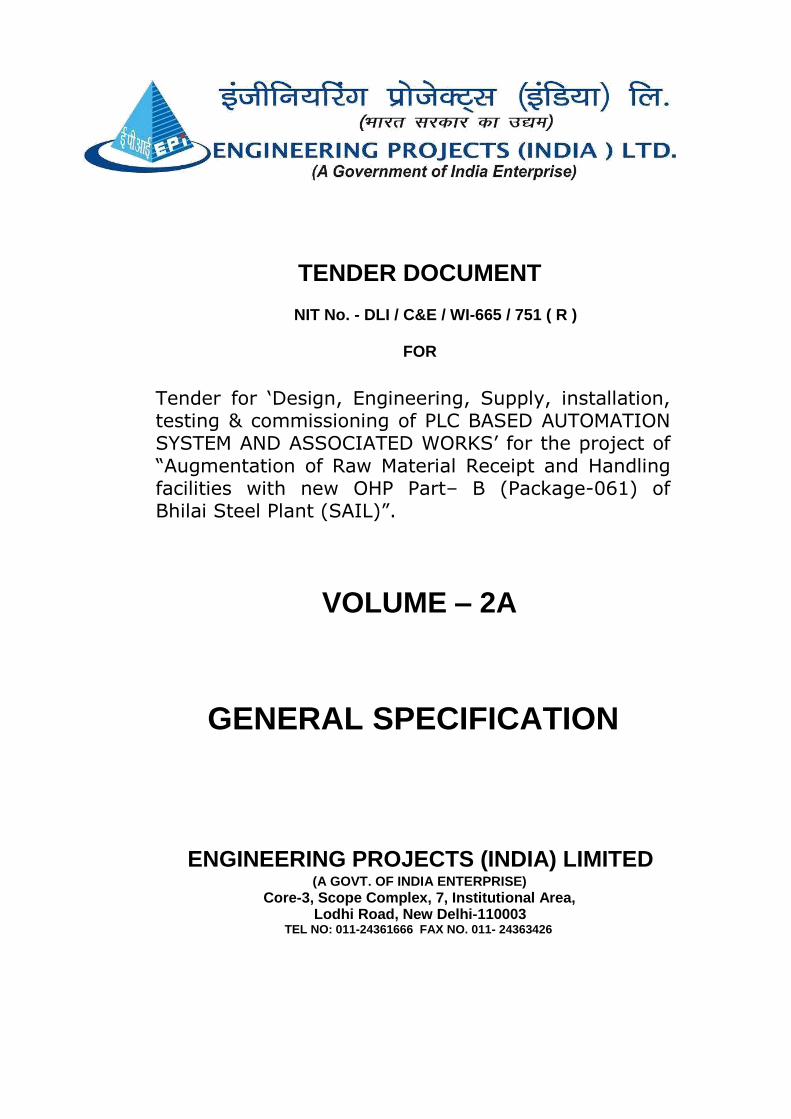
TENDER DOCUMENT
NIT No.- DLI / C&E / WI-665 / 751 (R )
FOR
Tender for „Design, Engineering, Supply, installation, testing & commissioning of „PLC
BASED AUTOMATION SYSTEM AND ASSOCIATED WORKS‟ for the project of “Augmentation of Raw Material Receipt and Handling facilities with new OHP Part– B (Package- 061) of Bhilai Steel Plant (SAIL)”.
VOLUME- 2
TECHNICAL PART
ENGINEERING PROJECTS (INDIA) LIMITED (A GOVT. OF INDIA ENTERPRISE)
Core-3, Scope Complex, 7, Institutional Area, Lodhi Road, New Delhi-110003
TEL NO: 011-24361666 FAX NO. 011- 24363426
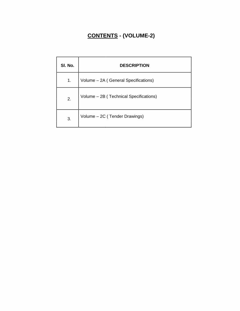
CONTENTS - (VOLUME-2)
Sl. No. DESCRIPTION
1. Volume – 2A ( General Specifications)
2. Volume – 2B ( Technical Specifications)
3. Volume – 2C ( Tender Drawings)
TENDER DOCUMENT
NIT No. - DLI / C&E / WI-665 / 751 ( R )
FOR
Tender for „Design, Engineering, Supply, installation, testing & commissioning of PLC BASED AUTOMATION SYSTEM AND ASSOCIATED WORKS‟ for the project of “Augmentation of Raw Material Receipt and Handling facilities with new OHP Part– B (Package-061) of Bhilai Steel Plant (SAIL)”.
VOLUME – 2A
GENERAL SPECIFICATION
ENGINEERING PROJECTS (INDIA) LIMITED (A GOVT. OF INDIA ENTERPRISE)
Core-3, Scope Complex, 7, Institutional Area, Lodhi Road, New Delhi-110003
TEL NO: 011-24361666 FAX NO. 011- 24363426

CONTENTS (VOLUME-2A)
Sl. DESCRIPTION
No.
1. Introduction
2. General scope and Battery Limits
3. Brief System Description
4. Project Synopsis and GTR
5A List of Approved Vendors
5B Preferred Makes
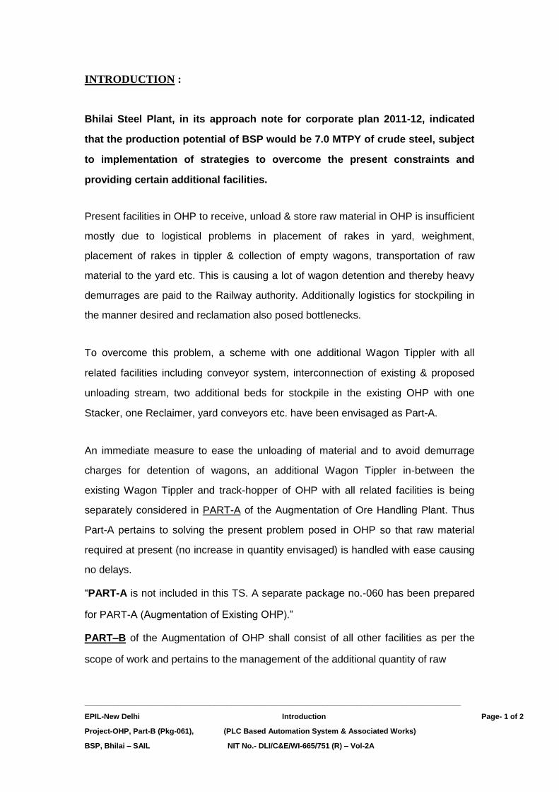
INTRODUCTION :
Bhilai Steel Plant, in its approach note for corporate plan 2011-12, indicated
that the production potential of BSP would be 7.0 MTPY of crude steel, subject
to implementation of strategies to overcome the present constraints and
providing certain additional facilities.
Present facilities in OHP to receive, unload & store raw material in OHP is insufficient
mostly due to logistical problems in placement of rakes in yard, weighment,
placement of rakes in tippler & collection of empty wagons, transportation of raw
material to the yard etc. This is causing a lot of wagon detention and thereby heavy
demurrages are paid to the Railway authority. Additionally logistics for stockpiling in
the manner desired and reclamation also posed bottlenecks.
To overcome this problem, a scheme with one additional Wagon Tippler with all
related facilities including conveyor system, interconnection of existing & proposed
unloading stream, two additional beds for stockpile in the existing OHP with one
Stacker, one Reclaimer, yard conveyors etc. have been envisaged as Part-A.
An immediate measure to ease the unloading of material and to avoid demurrage
charges for detention of wagons, an additional Wagon Tippler in-between the
existing Wagon Tippler and track-hopper of OHP with all related facilities is being
separately considered in PART-A of the Augmentation of Ore Handling Plant. Thus
Part-A pertains to solving the present problem posed in OHP so that raw material
required at present (no increase in quantity envisaged) is handled with ease causing
no delays.
“PART-A is not included in this TS. A separate package no.-060 has been prepared
for PART-A (Augmentation of Existing OHP).”
PART–B of the Augmentation of OHP shall consist of all other facilities as per the
scope of work and pertains to the management of the additional quantity of raw
__________________________________________________________________________________________ EPIL-New Delhi Introduction Page- 1 of 2 Project-OHP, Part-B (Pkg-061), (PLC Based Automation System & Associated Works) BSP, Bhilai – SAIL NIT No.- DLI/C&E/WI-665/751 (R) – Vol-2A

material required to produce 7MTPY of Crude Steel. The major facilities envisaged
are a Wagon Tippler, two Track Hopper and a new OHP (OHP-II) with six numbers of
beds of stockpile, three Stackers and four Reclaimers and related conveyors to feed
new Blast Furnace BF#8 and SP-III (both modules). The existing conveyors R101/ 102 series shall now feed the new RMP plant for new
SMS-III; however original route from existing OHP-I to Sinter Plant-III will still exist for
emergency..
__________________________________________________________________________________________ EPIL-New Delhi Introduction Page- 2 of 2 Project-OHP, Part-B (Pkg-061), (PLC Based Automation System & Associated Works) BSP, Bhilai – SAIL NIT No.- DLI/C&E/WI-665/751 (R) – Vol-2A
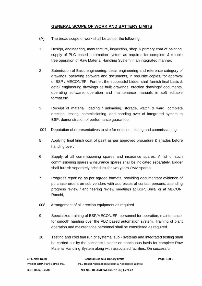
GENERAL SCOPE OF WORK AND BATTERY LIMITS
(A) The broad scope of work shall be as per the following:
1 Design, engineering, manufacture, inspection, shop & primary coat of painting,
supply of PLC based automation system as required for complete & trouble
free operation of Raw Material Handling System in an integrated manner.
2 Submission of Basic engineering, detail engineering and reference category of
drawings, operating software and documents, in requisite copies, for approval
of BSP / MECON/EPI. Further, the successful bidder shall furnish final basic &
detail engineering drawings as built drawings, erection drawings/ documents,
operating software, operation and maintenance manuals in soft editable
format.etc.
3 Receipt of material, loading / unloading, storage, watch & ward, complete
erection, testing, commissioning, and handing over of integrated system to
BSP, demonstration of performance guarantee.
004 Deputation of representatives to site for erection, testing and commissioning.
5 Applying final finish coat of paint as per approved procedure & shades before
handing over.
6 Supply of all commissioning spares and insurance spares. A list of such
commissioning spares & insurance spares shall be indicated separately. Bidder
shall furnish separately priced list for two years O&M spares.
7 Progress reporting as per agreed formats, providing documentary evidence of
purchase orders on sub vendors with addresses of contact persons, attending
progress review / engineering review meetings at BSP, Bhilai or at MECON,
Ranchi,
008 Arrangement of all erection equipment as required
9 Specialized training of BSP/MECON/EPI personnel for operation, maintenance,
for smooth handing over the PLC based automation system. Training of plant
operation and maintenance personnel shall be considered as required.
10 Testing and cold trial run of systems/ sub - systems and integrated testing shall
be carried out by the successful bidder on continuous basis for complete Raw
Material Handling System along with associated facilities. On successful
EPIL-New Delhi General Scope & Battery limits Page- 1 of 3 Project-OHP, Part-B (Pkg-061), (PLC Based Automation System & Associated Works)
BSP, Bhilai – SAIL NIT No.- DLI/C&E/WI-665/751 (R) )-Vol-2A

commissioning of the various sub-systems of the RMHS, PG test of the entire
plant shall be carried out as per the procedure
11 Receiving delivery of items at site, their proper storage, and handling at site,
watch and ward services etc.
12 Getting BSP/ MECON approval for the drawings prepared by the successful
bidder/their sub-vender obtaining required approval from statutory authorities,
providing adequate personnel, equipment, tools & tackles for timely completion
of the project.
13 For detailed scope of work and design parameters on various sub-systems &
facilities, technical specs and scope of work for PLC based automation system
and associated works as given in the volume-2B of tender document shall be
referred to.
(B) The major equipment to be installed for OHP Part B Project shall be as
follows:-
• A new OHP II Yard with 3 nos. twin boom stackers (TBS 1to3) and 4 nos.
bucket wheel reclaimers (BWR 1to4).
• An additional wagon-Tippler (WT B1).
• Two new track hoppers of 210m length each (TH B1)(Excluding
maintenance bay,with four compartments each side).
• 4 nos. paddle feeders in the new track hoppers with all automation to
discharge @1500t Ore fines/Lime stone etc. to down conveyors.
• An additional series of conveyor from OHP I to JH-20 and JH-42.
• New conveyor line for proposed Lime Dolomite plant RMP III and proposed
SMS-III.
• Up gradation of capacity of existing shuttle conveyors J9BRSC1.
• Sixteen no Belt Weigh Scales on conv. Z7-C3, Z4B-C1, Z4A-C1, Z5A-C1,
Z5B-C1, Z6A-C1, Z6B-C1, Z1C1, Z1C2, Z2C1, Z2C2, J9C1, L4C1, L10C1,
J20C3 & J17BC1shall be in contractor’s scope.
• Four nos. In Line magnetic separators over conv. Z2C1, Z2C2, Z1C1 &
Z1C2 each shall be in bidder’s scope.
• One no. diverter gate below conveyor L4C1.
• Electric hoists, winch, mobile belt changing machine, etc. at various
locations as specified. . EPIL-New Delhi General Scope & Battery limits Page- 2 of 3 Project-OHP, Part-B (Pkg-061), (PLC Based Automation System & Associated Works)
BSP, Bhilai – SAIL NIT No.- DLI/C&E/WI-665/751 (R) )-Vol-2A
• Provision of Weighbridges for weighment of incoming Raw materials
• 2 nos. belt feeders of rated/designed cap. 1500/1800 tph with BW 2000mm
(minimum) & maximum belt speed 0.8 m/sec .
BATTERY LIMITS
An overall battery limit of the Raw Material Handling System has been
described in the “Brief System Description” as enclosed with this tender
document and the Flow Diagram – Drawing No.
MEC/S/9101/11/17/0/00/00/061.B01/R3 (2 sheets) for OHP- II.
1. Battery limits for New Ore Handling Plant (OHP-II) comprises of the
following:
• New Ore Handling Plant (OHP-II) –From new Wagon Tippler WT # B1
and new track hoppers to the Ore storage bed for Stacking, reclaiming
& transportation to various units, including
¾ Lump Ore, limestone, dolomite etc. from OHP-II to New Blast
Furnace #8. (Through Junction house Z 15)
¾ Iron Ore fines, limestone & dolomite to both modules of
Sintering Plant-III. (Through Junction house Z 11) from OHP II
2. Proposed modifications/ up-gradations are:-
• An additional series of conveyor from OHP-I to new junction house J-20
and JH-42(Exst’g).
3. Feeding Limestone & dolomite to New Lime Dolo Plant RMP III and New
Steel Melting Shop SMS III :
This includes providing a discharge facility below belt conveyors R103A &
R104A at Junction House JN#102 (With suitable modifications of Jn House
#102) so as to feed new conveyor L1C1 as well as existing belt conveyors
R105 & R106. Limestone/dolomite/iron ore received from existing OHP-I will be
supplied to the junction house JH L6 of proposed new RMP III as well as
junction house JH L10 through surge bin building JH L9 before proposed new
SMS-III. The conveyor feeding raw material to RMP III from junction house JH
L6 and feeding raw material to SMS III from JH L10 is not in the scope of this
package. However junction houses JH L6 and JH L10 are in scope of this
package.
-----------------
EPIL-New Delhi General Scope & Battery limits Page- 3 of 3 Project-OHP, Part-B (Pkg-061), (PLC Based Automation System & Associated Works)
BSP, Bhilai – SAIL NIT No.- DLI/C&E/WI-665/751 (R) )-Vol-2A

Page 1 of 12
03.00 BRIEF SYSTEM DESCRIPTION
The turnkey package of this Contract Document comprises of the following
sub-systems:
New Ore Handling Plant (OHP-II) including receiving, unloading,
Stacking & Reclaiming and finally transporting of Raw Material
required for Blast Furnace #8, Sinter Plant-III.
New conveyor line for New Lime Dolomite plant RMP3 and for
proposed SMS-III.
Modifications/ up-gradations of existing equipment, including:
o An additional series of conveyor from OHP I to JH-20 and JH-
42(Exst’g) parallel to existing route
o Up gradation of capacity of existing shuttle conveyors J9BRSC1.
03.01 New Ore Handling Plant (OHP-II)
The raw material to be handled by the proposed system is mainly, Iron Ore
Lump, Iron Ore Fines, Lime Stone (BF grade), Lime Stone (SMS grade),
Dolomite (BF grade), Dolomite (SMS grade), Quartzite, Manganese ore.
These raw materials are mainly required for Blast Furnace, Sinter Plant,
Lime-Dolomite Plant, SMS. All the raw materials will be received at the
plant boundary by rail. The type of Wagon will be BOXN, BOXNHA, BOY,
BOBRN, BOST, BOBS, BOXNEL, BOYL,BOXN HS etc which will transport
the raw materials depending upon the location of loading and type of raw
materials.
03.01.01 Design Considerations
The Ore Handling Plant (OHP-II) has been planned based on the following
assumption:
A. Size of Raw Material
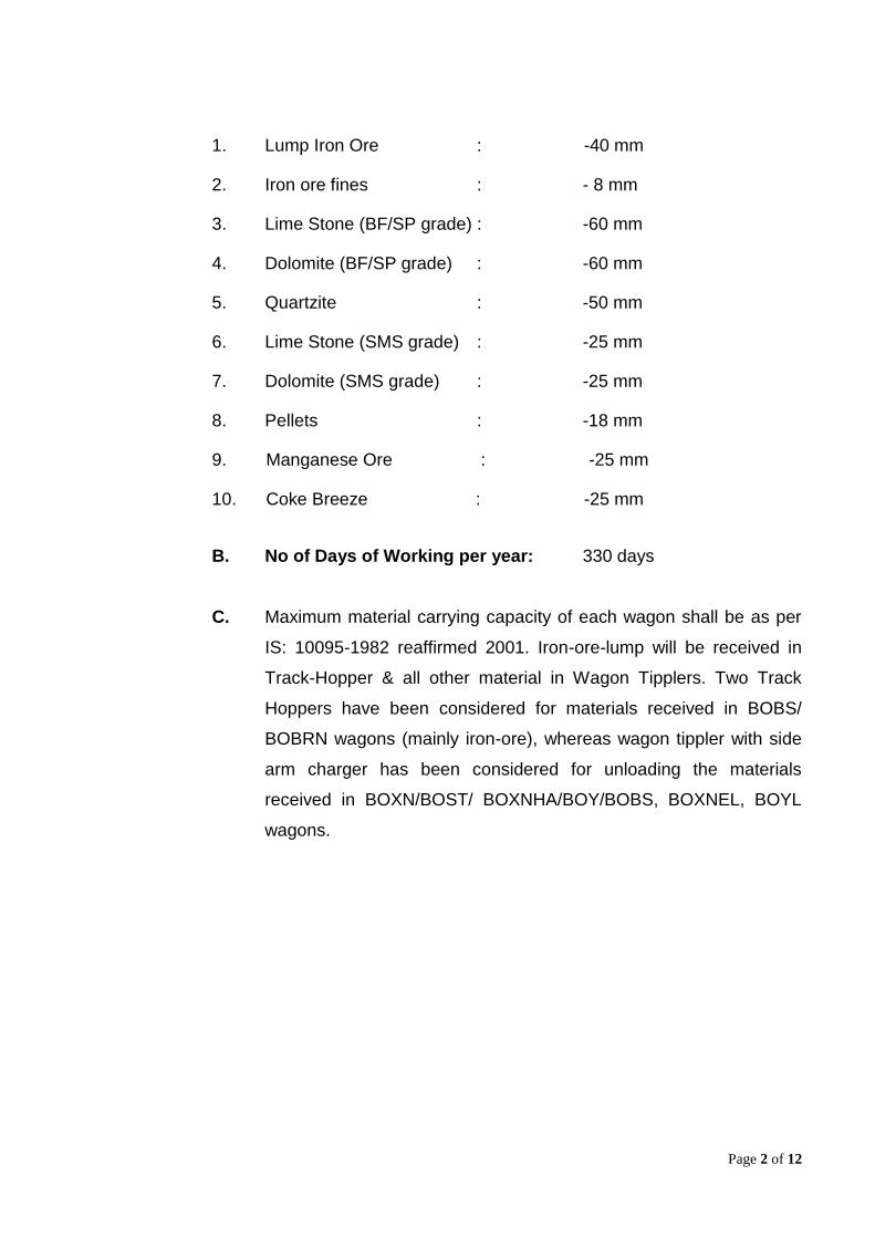
Page 2 of 12
1. Lump Iron Ore : -40 mm
2. Iron ore fines : - 8 mm
3. Lime Stone (BF/SP grade) : -60 mm
4. Dolomite (BF/SP grade) : -60 mm
5. Quartzite : -50 mm
6. Lime Stone (SMS grade) : -25 mm
7. Dolomite (SMS grade) : -25 mm
8. Pellets : -18 mm
9. Manganese Ore : -25 mm
10. Coke Breeze : -25 mm
B. No of Days of Working per year: 330 days
C. Maximum material carrying capacity of each wagon shall be as per
IS: 10095-1982 reaffirmed 2001. Iron-ore-lump will be received in
Track-Hopper & all other material in Wagon Tipplers. Two Track
Hoppers have been considered for materials received in BOBS/
BOBRN wagons (mainly iron-ore), whereas wagon tippler with side
arm charger has been considered for unloading the materials
received in BOXN/BOST/ BOXNHA/BOY/BOBS, BOXNEL, BOYL
wagons.
Page 3 of 12
03.01.02 UNLOADING, STORAGE, BLENDING AND RECLAIMING IN OHP-II
One number Wagon tippler WT no.B1 along with a Track Hopper TH-B1
with two parallel tracks on it have been envisaged for unloading Iron ore
(lump and fines), Limestone & Dolomite (both BF grade and Sinter Plant
grade), Mn-ore, Quartzite etc.
The Wagon Tippler shall be of Rota-side type capable of unloading BOXN
and proposed BOXNHA ,BOXNHS, BOBS, BOY wagons as per IS:10095-
1982, reaffirmed 2001. The rated unloading capacity shall be rated 20
Tips/hour. Adequate system of handling sticky rakes such as vibrator/ air
blaster shall be provided.
25t wagon axle load and 110t gross weight of wagons (BOX, BOXN, BOXN
HA, BOXN HS, BOXN EL, BOYEL) to be considered for design of Wagon
Tippler and track hopper. 2 nos. Weighbridges included in contractor's
scope. The location of Weigh Bridge shall presently be considered at entry
of pre hopper yard. However as the total railway track is being engineered
by RITES, the location of Weigh Bridge may under go change in detailed
engineering stage. The drawings of wagon tippler/track hopper shall be
subjected to approval by RITES /SECR/RDSO as applicable.
The placement of rakes shall be done by Side arm chargers capable of
handling a full rake BOXN, BOXNHA, BOBS, BOY, BOXN EL, BOYEL
wagons.
Two nos. of track hopper each of length 210 m excluding maintenance bay
and holding capacity of 6000 t each considering material of bulk density of
1.6 t/ cu.m. shall be included in contractor's scope. The side angle of
hopper with vertical shall be minimum 60 deg. Each hopper shall have four
compartments. Track hopper envisaged to accommodate minimum 18
BOBS wagons. Contractor to maintain sufficient height of the track hopper
superstructure to take care of OHE.
Page 4 of 12
Total 4 nos. Electric hoist of 5 t capacity shall be provided for maintenance
of Paddle Feeder at both ends of Track Hopper building. Two nos. double
door pressurized cabin shall be provided for paddle feeder inside the track
hopper tunnel. Anti-derailment device/ check rail shall be provided in the
track hopper subject to approval of RITES. Supply / Laying of 60 kg/ m rail
with continuous MS insert plate within track hopper building only are in
scope of contractor.
In addition to the above, one dedicated compressor station at track hopper
TH-B1for unloading of BOBRN wagons is to be provided. Compressed air
connection to BOBRN wagons to be provided at 15 mts interval. The
details of requirement of compressed air, the pressure and type shall be
obtained from RDSO. Other points as applicable for compressed air station
shall be considered as per CS for compressed air facilities indicated else
where.
Provision of adequate illumination should be there on both pre & post
tippler as well as on Merry Go Round circuit.
Two belt feeders below Wagon Tippler shall discharge the raw material on
either of two conveyors i.e. Z1-C1 or Z1-C2 which, in turn will discharge the
material at Jn House JH-Z1. From Jn House JH-Z1, conveyors Z3-C1 &
Z3-C2 will carry the material and discharge at JH-Z3. There will be three
incoming conveyors in Junction House JH-Z3. The tail end of two
conveyors Z3-C1 & Z3-C2 will start from JH-Z1 and Belt conveyor Z3-C3
from JH-Z2. Junction house JH-Z2 shall be located in between the JH-Z1 &
JH-Z3.
The track hopper with four nos. paddle feeders of 1500 tph each, two on
conveyors Z2-C1 and two on conv Z2-C2 has been envisaged. From Jn.
House JH- Z2, either of three conveyors Z3-C1, Z3-C2 (coming from JH-
Z1) & Z3-C3 (begin from JH-Z2) shall carry the material upto Jn house JH -
Z3. Reversible shuttle conveyors Z2RSC1/2 at JH-Z2 will facilitate to
discharge the material on either of any three conveyors. Therefore, JH-Z2
Page 5 of 12
shall be designed suitably so as to receive material from any of the
conveyors coming from Track Hoppers. Non sticky liners/ polymer liners
are to be fixed in the track hoppers to improve flowability.
Suitable interchangeability shall be provided below Wagon Tipplers and
Track Hoppers for the conveyors by providing Diverter gates.
In Jn House Z3, three nos. Reversible Shuttle conveyors no. Z3-RSC1,2&3
can feed any one of conveyor no. Z4C1, Z4C2 and Z4C3. Conveyor no.
Z4C1, Z4C2 and Z4C3 shall be provided with fixed tripper at JH Z4A . In
the fixed tripper at JH-Z4A ,3 nos. flap gate shall be provided to feed
material either to itself or to conv Z7C1& Z7C2 (as by pass arrangement).
Conveyor no. Z4C1, Z4C2 and Z4C3 shall feed on to conveyor Z5C1,
Z5C2 and Z5C3 in JH-Z4. Each of the three Conveyor Z5C1, Z5C2 and
Z5C3 shall be from JH-Z4 to JH-Z6B. Conveyor Z5C1, Z5C2 and Z5C3
shall be provided with jumbo gallery (suitable for mobile trippers) from JH-
Z4 to JH-Z4B and from JH-Z4B to JH-Z5B. Conv Z5C1, Z5C2 and Z5C3
are capable of feeding the stacking conv. Z4B-C1 and Z5B-C1 as well as
itself through mobile trippers from JH-Z4B and JH-Z5B respectively.
In JH-Z6B Conveyor Z5C1, Z5C2 and Z5-C3 shall feed stacking
conveyor Z6B-C1. In JH-Z6B conveyor Z5-C1 & Z5-C2 shall have
provision to feed future conveyors. Maintenance hoist of minimum 5t cap
shall be provided for the trippers..
The raw material can either be transported via. JH House Z4B, Z5B or Z6B
to the respective stacking conveyors Z4B-C1, Z5B-C1 & Z6B-C1 for
stockpiling or can be fed directly to the reclaiming conveyors Z7-C1/ Z7-C2
(from JH-Z4A to JH-Z7) which means convey material directly from the WT/
Track Hopper to:
(a) To the Blast Furnace#8 Stock House
(b) To the Fuel & Flux crushing circuit of Sinter Plant-III.
Suitable interchangeability shall be provided at Junction house Z4B, Z5B
or Z6B for the conveyors by providing 2-way chutes in mobile tripper. 5T
Page 6 of 12
Electric hoist each shall be provided at JH-Z5B & JH-Z6B. Whereas, JH-
Z4B shall be designed only as a transfer point.
The Stacking conveyors Z4B-C1, Z5B-C1 & Z6B-C1 can form a stockpile
30m wide, 350m long and 10.5 m (maximum) high with the help of Twin
boom stackers.
Suitable number of electrically operated Under-Slung Cranes, Hoists etc.
shall be provided in all floors of Junction Houses and building for
maintenance of equipment. Electro-Magnetic Separators, In-Line Magnetic
Separators, Metal Detectors, Belt- Weigh-Scales, Air-Blasters/ Bin
Vibrators shall be provided to make the system complete and the
operation/ maintenance smooth.
03.01.03 STORAGE AND RECLAMATION OF ORE
From the Wagon Tipplers WT-B1 and the Track Hopper TH-B1, the raw
material may sometimes be fed directly to the consuming plant in case of
emergency. However, this shall not happen under normal circumstances,
when the three Twin-boom stackers over conveyors Z4B-C1, Z5B-C1 &
Z6B-C1 store the raw material in the designated place of the yard in bed
nos. 1 to 6. Flexibility shall be in built in the Jn Houses Z4B, Z5B, & Z6B to
ensure stacking is trouble free.
Bed blending system shall be possible with the stacker running to and fro
on the length of the pile -or- on a length between two defined position in
case more than one material is stored in a bed marked by travel limit
switches, which through a relay sequencing circuit, with time control-
reverses the traveling gear after the travel in each direction covering the
desired length of the pile. After a layer of some pre -determined amount is
deposited in one traveling direction of the stacker, probes fitted on the
Page 7 of 12
stacker boom gives it a “raise” signal as soon as a net height of material is
formed. The next layer is then formed.
Iron ore may require stockpile formation as described above for blending
and uniformity. However, the emphasis on blending shall be for iron ore
fines which shall be blended while stacking.
Four nos Bucket-wheel reclaimers have been envisaged for bed no. 1 to 6.
All stacking line conveyors feeders and stackers etc. shall have a rated
capacity of 1500 tph & a designed capacity of 1800 tph.
All reclaim line equipment shall have a rated capacity of 1500 tph and a
designed capacity of 1800 tph in the ore handling area.
Reclamation takes place by the conveyors Z4A-C1 (Bed no. 1), Z5A-C1
(Bed 2or 3), Z6A-C1 (Bed no.4 or 5) and Z7A-C1 (Bed no. 6) and the
reclaimed material via Jn House Z4A, Z5A, Z6A and Z7A shall reach Jn
House Z7. Two reclaim conveyors Z7-C1 and Z7-C2 between Z4A to Z7
will receive all the materials from yard for further transportation.
Reclamation from OHP takes place for the following circumstances:-
Feeding of iron ore lump, dolomite, limestone, manganese,
quartzite, pellet etc. to BF#8 stock house.
Transporting Limestone/ Dolomite (SP grade) and iron-ore fines to
fuel & flux crushing area for Sinter Plant-III.
Two streams of belt conveyors shall reclaim the material from new OHP-B
yard to above places. Belt conveyor Z7-C1 & C2 shall carry the material
and transport thru Z8-C1, C2, Z9-C1, C2, Z10-C1, C2 to Z11-C1& C2 to
Junction house JH-Z11. Junction House-Z11 can discharge the material
either to existing conveyors R103/ R104 of Sinter Plant-III or proposed
conveyor Z12-C1/ C2 of BF#8, with the help of reversible conveyors. To
Page 8 of 12
receive the material from Z11-C1 & C2, suitable modification in existing
gallery of R103 & R104 is required. Also a junction house JH-Z11 with two
reversible conveyors & tail end of belt conveyors Z12-C1 & C2 shall be
erected above these conveyors. Further, conveyor Z12-C1 & C2 will feed
the material to conveyor Z13-C1&C2 at Junction House JH-Z13 and then
conveyor Z15-C1 &C2 shall discharge material onto conveyors (by BSP)
through diverter gates JH-Z15 and material shall move towards stock
house of BF#8.
Suitable Junction houses with RCC floors, diverter gates & galleries shall
be provided to transfer the material from one conveyor to another. The
scope of contractor shall finish at JH-Z15 with complete drive and
discharge facilities. The receiving belt conveyor below Z15-C1 & C2 shall
be in the scope of Employer i.e. BSP. However, JH-Z15 shall have a
provision (inserts/ foundation bolts) to erect outgoing conveyors to Stock
House.
03.02 OTHER ADDITIONS/ MODIFICATIONS AND UPGRADATION IN EXISTING
OHP (REF. DRG. NO. MEC/S/9101/11/17/0/00/00/061.B01/ R2)
1. An Additional series of conveyor from OHP to J-20 and JH-42(Exst’g)
Another proposed conveyor No J9-C1 parallel to J9-C3/J9-C4, besides
conveyors R-102, shall start from Jn. House JH-9B and shall discharge the
material to a proposed conveyor J9H-C1 in new Junction House JH-9H,
which in turn feeds to conveyor J10A-C1 in JH-9H. From JH-9H conveyor
J10A-C1 can feed proposed conveyor J11-C3, J11-RC2, J14-C2/J12-C2
(Exst’g) ,J15-C2. Conv J15-C2 shall feed new reversible conv. J15-RC1 in
new junction house JH-15B, which in turn can feed either existing SMS-II
feeding conv. J15A-C1 or new conv. J17A-C1. Another new conv.J15B-C1
which shall receive sinter from existing conv. SS-10 shall feed new
conveyor J17A-C1 in new junction house JH-15B which in turn shall
discharge onto new conv. J17B-C1 in new junction house JH-17A.
Conveyor J17B-C1 shall discharge to either of the two conveyors J20C3 or
Page 9 of 12
extended J44-C5(exist) through a adjustable diverter gate in new junction
house JH-17B. Conveyor J20-C3 shall be provided with one no. belt weigh
scale and have provision of discharging onto existing sinter carrying
conveyor J27-C5 (Exst’g) in junction house JH-20 (Exst’g.
Necessary modification/strengthening shall be carried out in junction house
J42 to take care of additional loads by new conveyor. Suitable electrical
interlock shall be provided between the conveyors J27-C5 & J20-C3 in
junction house JH-20 to trip all the incoming conveyors in case feed rate
exceeds capacity (500tph) of the corresponding downstream conveyor J27-
C5. Similar interlock shall also be provided between J17B-C1 & extended
J44-C5(exist) in junction house JH-J17B to avoid any spillage/chute
blockage. These additional conveyors with gate will facilitate a new
additional route for BF # 7.
All above conveyor shall run adjacent to the existing conveyor/ galleries at
same elevation. Junction houses JH-9H, JH-10A, JH-14A,JH-15B, JH 17A
and JH- 17B shall be new Junction houses. For conveyor no. J11-C3,
J11-RC2, J14-C2, J15-C2, J15-RC1, J15B-C1, J17A-C1, J20-C3 & J44-C5,
the existing junction houses (JH-10, JH-11, JH-14, JH-15, JH- 17, JH-20
and JH-42) shall be suitably modified to suit proposed conveyor transfer
points/crossing over.
2. Up gradation of Reclaiming conveyors
The capacity up-gradation and utilization of reclaim conveyors are of
utmost importance to ensure smooth operation in the OHP.
The list of conveyors in the reclaiming circuit that shall be upgraded to 1500
tph are given in table 03.01.
Table 03.01
SL
No CONVEYOR NO
EXISTING PROPOSED
BELT
WIDTH
mm
CAP
BELT
WIDTH
mm
CAP
tph
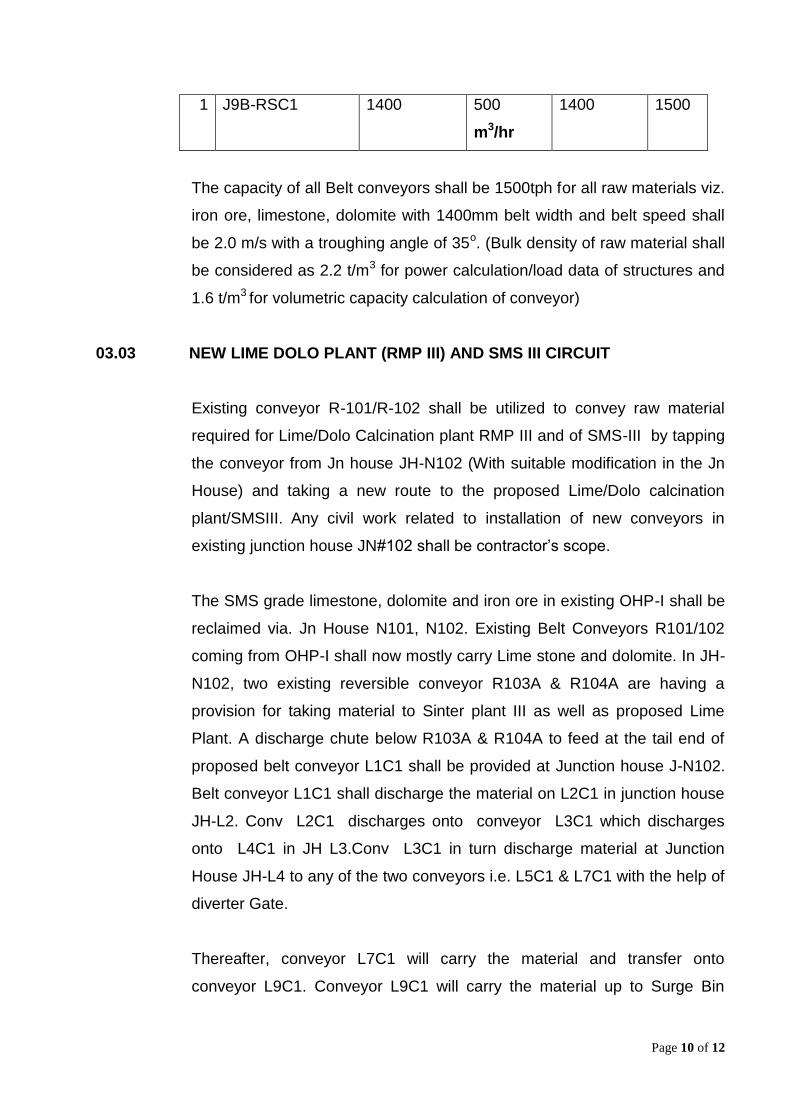
Page 10 of 12
1 J9B-RSC1
1400
500
m3/hr
1400
1500
The capacity of all Belt conveyors shall be 1500tph for all raw materials viz.
iron ore, limestone, dolomite with 1400mm belt width and belt speed shall
be 2.0 m/s with a troughing angle of 35o. (Bulk density of raw material shall
be considered as 2.2 t/m3 for power calculation/load data of structures and
1.6 t/m3 for volumetric capacity calculation of conveyor)
03.03 NEW LIME DOLO PLANT (RMP III) AND SMS III CIRCUIT
Existing conveyor R-101/R-102 shall be utilized to convey raw material
required for Lime/Dolo Calcination plant RMP III and of SMS-III by tapping
the conveyor from Jn house JH-N102 (With suitable modification in the Jn
House) and taking a new route to the proposed Lime/Dolo calcination
plant/SMSIII. Any civil work related to installation of new conveyors in
existing junction house JN#102 shall be contractor’s scope.
The SMS grade limestone, dolomite and iron ore in existing OHP-I shall be
reclaimed via. Jn House N101, N102. Existing Belt Conveyors R101/102
coming from OHP-I shall now mostly carry Lime stone and dolomite. In JH-
N102, two existing reversible conveyor R103A & R104A are having a
provision for taking material to Sinter plant III as well as proposed Lime
Plant. A discharge chute below R103A & R104A to feed at the tail end of
proposed belt conveyor L1C1 shall be provided at Junction house J-N102.
Belt conveyor L1C1 shall discharge the material on L2C1 in junction house
JH-L2. Conv L2C1 discharges onto conveyor L3C1 which discharges
onto L4C1 in JH L3.Conv L3C1 in turn discharge material at Junction
House JH-L4 to any of the two conveyors i.e. L5C1 & L7C1 with the help of
diverter Gate.
Thereafter, conveyor L7C1 will carry the material and transfer onto
conveyor L9C1. Conveyor L9C1 will carry the material up to Surge Bin

Page 11 of 12
building JHL9 through reversible shuttle conv. JL9RSC1. Surge bin building
JHL9 shall have 3 nos. bunkers of minimum geometric capacity 190 cub m
each for storing iron ore lump/limestone /bauxite. Suitable rod gate and
motorized rack and pinion gates shall be fitted at the bottom of bunkers.
Three (3) nos. VVF controlled vibro feeders of 420 tph capacity each shall
withdraw material from bunker and discharge it onto conveyor L10C1 which
shall convey up to Junction house JH L10 for onward transportation to
Surge Bin Building for SMS-III (Surge bins with Vibro-feeder as shown in
flow diagram at JH-L9 are in contractor’s scope.) through SMS feeding
conveyor. Conveyor L10C1 complete with discharge facilities and junction
house JH L10 shall be in the scope of contractor and SMS feeding
conveyor shall be in the scope of employer.
The other conveyor L5C1 shall receive material from conveyor L4C1 and
discharge at JH-L5 on to conv. L6C1 which shall convey up to junction
house JH-L6 and discharge onto lime plant feeding conveyor for onward
transport to Lime & Dolomite calcination plant RMP III. Conveyor L6C1
complete with discharge facilities and junction house JH L6 shall be in the
scope of contractor .However lime plant feeding conveyor shall be in the
scope of employer i.e. BSP.
Calcined lime/dolomite is received from the day bins of lime/dolo product
storage building of RMP III onto conveyor L8C1.Conv. L8C1 discharges
onto conv. L9C2 in JH L8 which in turn discharges onto conveyor L10C1 in
Surge Bin building JH L9. This finished product of RMP III is transported to
the junction house JH L10 by conveyors L10C1 which shall also carry
limestone, bauxite, iron ore received directly from OHP I yard to SMS III.
The scope of contractor starts from tail end on conveyor L8C1 including
skirt boards.
A fixed hopper of 8 cub m capacity on conveyor L10C1 near JH L9 with
VVF controlled vibro feeder of 420 tph capacity shall also be used to
transport coke fines as and when required in the storage bins of the bulk
material charging system of SMS III. Any other material e.g limestone/ DRI
Page 12 of 12
can also be transported under emergency conditions through fixed hopper.
Suitable ramp shall be provided to unload the material over hopper.
03.04 Two separate Automatic Sampling system complete with sample cutter,
collection, sizing, crushing and grinding shall be provided for the RMHS
system.
03.05 AREA REPAIR SHOP & SUB-STORE: Refer Chapter 04.06 & 04.07 for
details.
03.06 Welfare/ Office Building: Refer Chapter 04.04 for details.
03.07 Workers rest room: Refer Chapter 04.04 for details.
EPI – New Delhi NIT-DLI/C&E/WI-665/751 (R) –Vol-2A Page 1 of 38
GENERAL SPECIFICATION
GENERAL
The following General Specification shall be read in conjunction with General
Technical Specification (GTS) of Bhilai Steel Plant, SAIL. If there are any
provisions in these General Specification, which are at variance with the
provisions of General Technical Specification (GTS) of Bhilai Steel Plant, SAIL,
the provisions in these General Specification shall take precedence. 1.0 PROJECT SYNOPSIS 1.1 Site Conditions 1.1.1 Location
Bhilai Steel Plant (BSP), SAIL is located at Bhilai in Durg District of the state of Chhatisgarh in the central region of India. The site lies between 21.15
o North
latitude and 81.22o East latitude. The nearest convenient railhead is Durg which is
about 12km west Bhilai. Bhilai /Durg stations are on the Howarh-Mumbai rail line of SEC Railway of the Indian railways.
The location of Bhilai is as follows:
From New Delhi, the national capital -- 1359 kms From Kolkata -- 868 kms From Chennai -- 1269 kms
From Mumbai -- 1100 kms
The distance from State Capital Raipur to Bhilai Steel Plant is 30km. It is well
connected by the rail and road network. The nearest national highways are NH 6 & NH 43 crossing through Raipur.
1.1.2 Meteorological Data
In the absence of meteorological data at Bhilai/Durg, the data of the state capital
Raipur, 30kms away, are considered. The meteorological details at Raipur are
given below:
Ambient Temperature Absolute maximum : 47.7
o C
Absolute minimum : 3.9o C
Highest of mean monthly : 45.2o C
Ambient Air
Ambient air quality : Industrial
Relative Humidity
Maximum : 100%
EPI – New Delhi NIT-DLI/C&E/WI-665/751 (R) –Vol-2A Page 2 of 38
Average altitude of the land is 300 m above MSL. Temperature inside shop premises is
generally taken as 5o C above ambient, unless otherwise specified.
1.1.3 Infrastructure Facilities Outside the Plant
Railway
Bhilai Steel Plant is connected to Indian Railways network via Bhilai/Durg Stations
of SEC Railway on the Howarh-Mumbai line. The track gauge of SEC Railways as
well as of the plant tracks are standard broad gauge i.e 1676 mm.
Road
The plant is well connected to the country by road. National Highways NH6 &
NH43 both pass through Raipur.
Sea Port
The nearest sea port is Vishakhapattanam approximately 550 km away from the
site by rail.
Air Traffic
The nearest air port connected to the national network is Mana at Raipur, 30kms
away. 1.1.4 Infrastructure Facilities Inside the Plant
Railway
Minimum : 7%
Climate : Tropical Humid
Rainfall
Harvest rainfall in 24 hours : 370.3mm
Annual Average : 1288.8mm
Wind
Predominant wind direction : SW to NE (Oct- Feb) and West to East (Mar- Sep) Mean wind speed : 6.8 kmph
Maximum mind speed : 45 kmph
Altitude
EPI – New Delhi NIT-DLI/C&E/WI-665/751 (R) –Vol-2A Page 3 of 38
The track guage for the entire plant corresponds to the Indian Railway standard
broad guage i.e 1676mm.
Road
Main road and side of the Plant shall have roadways of 7.0m and 4.0m width
respectively and the temporary roads provided during the construction stage shall
be designed to cater the needs of movement of heavy construction vehicles.
2.0 GENERAL TECHNICAL REQUIREMENTS (GTR) 2.1 General Rules and Regulations
All plant units with respect to their location. layout, general arrangement and
design of equipment, structural design, etc. shall be safe to the personnel and
conform to the relevant statutory requirements issued by Chhatisgarh Government
and the Government of India but not limited to the following.
- Chhatisgarh State Factory Rules/Acts - Indian Electricity Rules/Acts - Electricity Regulatory Commission Act - Indian Petroleum Regulations/Acts - Indian Boiler Regulations/Acts - Indian Explosives Acts - Gas Cylinders Rules/Acts - Carbide of Calcium Rules/Acts - State and mobile Pressure Vessels Codes (unifired) Rules/Acts - Fire Protection Manual issued by Tariff Advisory Committee (India) - Pollution Control Regulations/Acts
Pollution control measures shall be provided considering the latest norms and
international standards. These should satisfy the stipulations of Central Pollution
Control Board and Department of Environment and the Forest, Government of
India.
2.1.1 Standard
Preferred Makes of Equipment & Supplies To restrict/minimize stock/inventory of spares, the Purchaser considering will limit the makes of equipment & supplies to those listed in the “preferred makes of
equipment and supplies” and list of approved vendors enclosed unless other-wise expressly so agreed
Unit of Measurement All dimensions & weights shall be given in metric system.
Language
All drawings, documents etc. shall be in English language.
EPI – New Delhi NIT-DLI/C&E/WI-665/751 (R) –Vol-2A Page 4 of 38
2.2 Safetey
2.2.1 Safety Regulations The Vendor shall comply with the, relevant Safety Rules and Regulations but not limited to the following: - Chhatisgarh State Factory Rules/Acts - Indian Electricity Rules/Acts - Electricity Regulatory Commission Act - Indian Petroleum Regulations/Acts - Indian Boiler Regulations/Acts - Indian Explosives Acts - Gas Cylinders Rules/Acts - Carbide of Calcium Rules/Acts - State and mobile Pressure Vessels Codes (Unifired) Rules/Acts - Fire Protection Manual issued by Tariff Advisory Committee (India) - Pollution Control Regulations/Acts
Strict attention shall be paid to all statutory regulations and safety rules for
prevention of accidents.
The safety posters/regulations for prevention of accidents shall be displayed by
the Vendor at appropriate places. Notices and warning signs shall be displayed for
all sources of dangers.
The Vendor is not permitted to construct any temporary road crossing on the rail
tracks for the sake of their convenience at work site.
When the work is carried out at night or in the obscure day light, adequate
arrangements for flood lighting in the working area shall be made by the Vendor at
his own cost and got approved by the Purchaser.
All handling/transport and the rigging equipment including lifting tools and tackles
shall be checked at regular intervals and kept in good and safe working condition.
A register is to be maintained regarding the results of periodical tests/checks and
other particulars in respect of each and every such equipment.
The Vendor must take sufficient care in moving his construction plant and
equipment from one place to another, so that those do not cause any damage to
the property of the Purchaser or obstruct construction activities of other Vendors.
The Vendor shall depute a full time safety engineer who will exclusively look after
all the jobs pertaining to safety at site and keep close liaison with
Purchaser/Consultant. He will be responsible for maintaining safe working
conditions at site, promoting safety consciousness among the workmen and
reporting to concerned authorities in case of accident/dangerous occurrences.
Before execution of work in hazardous area like

EPI – New Delhi NIT-DLI/C&E/WI-665/751 (R) –Vol-2A Page 5 of 38
- Gas contamination - Working at height - Storage of inflammable materials
- Danger of electric shocks
- Explosion risks
- Excavation more than 2m deep, etc. A protocol should be prepared in association with the agencies of the Purchaser /
Consultants.
2.2.2 Safety while Working with Explosives
Explosives shall not be used on the work site by the Vendor without the written
permission of the Purchaser and that too only in the manner and to the extent to
which it has been prescribed
Explosives shall be stored in special premises approved by Purchaser and at the
cost of the Vendor who shall be liable for all damages, loss or injury to any person
or property and shall be responsible for complying with all statutory obligations in
these respects. 2.2.3 Safety Appliances
The Vendor shall provide the safety appliances conforming to the relevant Indian
standards to all their workmen and supervisors engaged by them as well as by the
sub- contractors.
The Vendor shall ensure that all the workmen and supervisors, are using the
safety appliances regularly during work at site.
Any form of compensation in lieu of safety appliances shall not be permitted. Any
violation in safety provisions of failure to maintain safe working conditions will lead
to serious penalty on the Contractor and finally may lead to termination on the
Contract.
The workmen of the Vendor deployed for construction and erection in hazardous
areas shall be provided with personnel protective safety appliances of special
nature suitable for hazardous working conditions. 2.2.4 Safety during Construction/Execution
The Vendor shall be responsible for the safety of his workmen and employees.
The Vendor shall ensure that safety practices are followed so as to present
personal injury to his workmen and also to other persons working/passing by in
that area.
The Vendor shall ensure that in case of any accidents, the same are reported

EPI – New Delhi NIT-DLI/C&E/WI-665/751 (R) –Vol-2A Page 6 of 38
without delay to the Purchaser/Statutory Authorities as per Rules. In case of any injury/accident the Vendor shall bear all the expenditure for medical treatment
and shall pay the compensation in case of permanent disability or death.
The Vendor shall ensure that all personnel employed do not stray into others areas. Any injury caused due to this shall be the sole responsibility of the
Contractor.
The Vendor shall ensure that skilled labours required for specific works have necessary trade certificates and adequate experience of the job. This is likely to be checked by the Purchaser. The concerned operator, mechanics, electricians, fitters, riggers, etc. must be fully conversant with the hazards associated in
operation/maintenance of their relevant equipment.
2.2.5 Safer Working Platforms
• Vendor shall use strong and secured planks and boards of the right sizes. • These planks shall be painted at the edges brightly to warn the workers for any
misuse (usually zebra paint)
• Vendor shall make sure that scaffolds are erected by the trained scaffolders.
• Supervisors must inspect scaffolds once every week.
2.2.6 Falling Objects and Debris
• No loose materials which can fall down should be kept on the working platforms.
• Overhead shelters should be provided to minimize damage from tailing objects.
• Strong nets to be provided to catch these objects or debris.
• Nets must envelop all sides of the building.
2.2.7 Personal Safety Equipment
• Workers must wear approved safety helmets and shoes. • For those working in high places safety belts shall be provided. • The safety belts must be attached to strong anchorage points.
2.2.8 Operating Construction Machine
• Vendors shall make sure that those operating the construction machinery are
well trained for their jobs.
• The keys of such machinery shall be kept with the authorized persons. • The keys shall be removed after use of the machine.
2.2.9 Safer Electrical Installations
• Vendor shall use approved types of electrical sockets and plugs. • Proper insulators for all electrical wiring shall be provided. • Wiring should not be allowed to lie on the floor or on the ground.
2.2.10 Safety in Designing of Equipment
EPI – New Delhi NIT-DLI/C&E/WI-665/751 (R) –Vol-2A Page 7 of 38
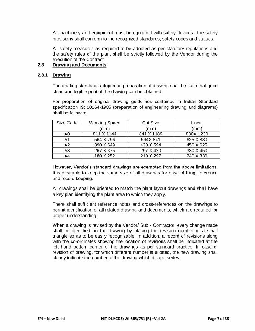
All machinery and equipment must be equipped with safety devices. The safety
provisions shall conform to the recognized standards, safety codes and statues.
All safety measures as required to be adopted as per statutory regulations and
the safety rules of the plant shall be strictly followed by the Vendor during the
execution of the Contract. 2.3 Drawing and Documents
2.3.1 Drawing
The drafting standards adopted in preparation of drawing shall be such that good
clean and legible print of the drawing can be obtained.
For preparation of original drawing guidelines contained in Indian Standard
specification IS: 10164-1985 (preparation of engineering drawing and diagrams)
shall be followed
Size Code Working Space Cut Size Uncut
(mm) (mm) (mm)
A0 811 X 1144 841 X 1189 880X 1230
A1 564 X 796 594X 841 625 X 880
A2 390 X 549 420 X 594 450 X 625
A3 267 X 375 297 X 420 330 X 450
A4 180 X 252 210 X 297 240 X 330
However, Vendor’s standard drawings are exempted from the above limitations.
It is desirable to keep the same size of all drawings for ease of filing, reference
and record keeping.
All drawings shall be oriented to match the plant layout drawings and shall have
a key plan identifying the plant area to which they apply.
There shall sufficient reference notes and cross-references on the drawings to
permit identification of all related drawing and documents, which are required for
proper understanding.
When a drawing is revised by the Vendor/ Sub - Contractor, every change made
shall be identified on the drawing by placing the revision number in a small triangle so as to be easily recognizable. In addition, a record of revisions along
with the co-ordinates showing the location of revisions shall be indicated at the
left hand bottom corner of the drawings as per standard practice. In case of revision of drawing, for which different number is allotted, the new drawing shall
clearly indicate the number of the drawing which it supersedes.

EPI – New Delhi NIT-DLI/C&E/WI-665/751 (R) –Vol-2A Page 8 of 38
Approval of drawings from the statutory authorities such as the Indian Boiler
Inspectorate, Inspectorate of Explosives, Electrical Inspector, etc. is the
responsibility of the Vendor/ Sub-Contractor.
Any additional drawings not specifically mentioned by the EPI/BSP/MECON but
are the required for the approval of drawings, shall be submitted by the Vendor/
Sub-Contractor.
The Title block of the drawing shall be enclosed as Annexure I.
2.3.2 Approval of Drawings
Approval of Vendor’s drawings will generally be accorded within four (4) weeks of
receipt.
Approval of Vendor’s drawings means that these will be checked for conformity
with applicable specifications and general conformity with the engineering
requirement for the areas covered in the scope of work. It is understood that
approval by the Purchaser’s Consultant does not include checking for drafting
and other errors but only reviews of basic concepts and general principles
involved.
The Vendor shall be responsible for any discrepancy, errors and omissions in the
drawings have been approved by the Purchaser/Consultants or not. The Vendor
shall bear all extra cost due to alterations necessitated by reasons of any
discrepancies, errors or omissions in the drawings and particulars supplied by
the Vendor.
Drawing furnished by the Vendor shall be certified as correct for use and shall
bear the signatures of responsible persons of the Vendor.
Approval of Vendor’s drawing shall not relieve the Vendor of his responsibility to
comply with the intent of the contract; manufacture/fabrication or procurement
prior to approval of drawings shall be at the Vendor’s risk.
The Vendor shall submit drawing to EPI/BSP/MECON for approval by the
Purchaser /Consultant as per clause 3.4 to 3.6 of GTR.
If the drawing is “Approved” then one print shall be returned back to the Vendor
duly stamped “Approved” by Consultant.
If the drawing is “Not approved” or “Approved as Noted”, then one stamped print
with appropriate comments shall be returned back to the Vendor for incorporation
of comments and re-submission of revised drawings for approval sets with in 7
days as per clause 3.4 to 3.6 of GTR.
EPI – New Delhi NIT-DLI/C&E/WI-665/751 (R) –Vol-2A Page 9 of 38
After approval of drawings the Vendor shall submit 12 sets of approved drawings
to the EPI. The Vendor shall incorporate the following note on the drawing before
“Approved by MECON vide letter no………….dtd…”
The drawing shall become a contract drawing after approval and there after the
Vendor shall not deviate from them in any way whatsoever except with the
written permission of the EPI/BSP/MECON.
All reference and information category drawings shall be submitted in 12 sets to
EPI. These drawings shall be submitted to Purchaser before forwarding the same
to erection Vendor at site for constructive/erection activities.
The information category drawings shall not be approved by the Consultant.
However, information category drawings shall be stamped “For Information Only”
and one set shall be returned back to the Vendor.
In case any discrepancy is observed on these drawing, same shall be informed
to the Vendor by marking the comments on the drawings. The Vendor shall
resubmit these drawings after incorporating the comments in 12 sets to the EPI.
After receipt of stamped “For Information Only” the Vendor shall submit 10 sets
of drawings to the EPI. The Vendor shall incorporate the following note on the
tracing before taking additional prints for submission to the EPI.
Stamped “For Information Only” by MECON vide their letter no…….. dtd…….
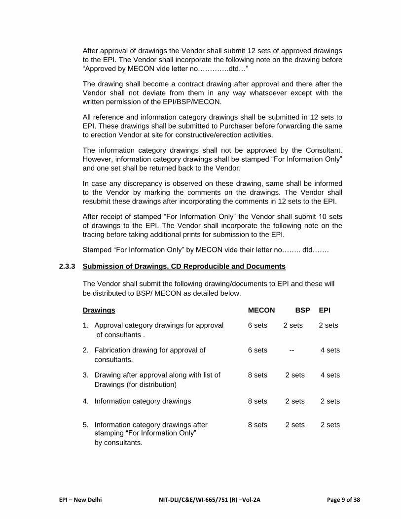
2.3.3 Submission of Drawings, CD Reproducible and Documents
The Vendor shall submit the following drawing/documents to EPI and these will
be distributed to BSP/ MECON as detailed below.
Drawings MECON BSP EPI
1. Approval category drawings for approval 6 sets 2 sets 2 sets
of consultants .
2. Fabrication drawing for approval of 6 sets -- 4 sets
consultants.
3. Drawing after approval along with list of 8 sets 2 sets 4 sets
Drawings (for distribution)
4. Information category drawings 8 sets 2 sets 2 sets
5. Information category drawings after 8 sets 2 sets 2 sets stamping “For Information Only”
by consultants.
EPI – New Delhi NIT-DLI/C&E/WI-665/751 (R) –Vol-2A Page 10 of 38
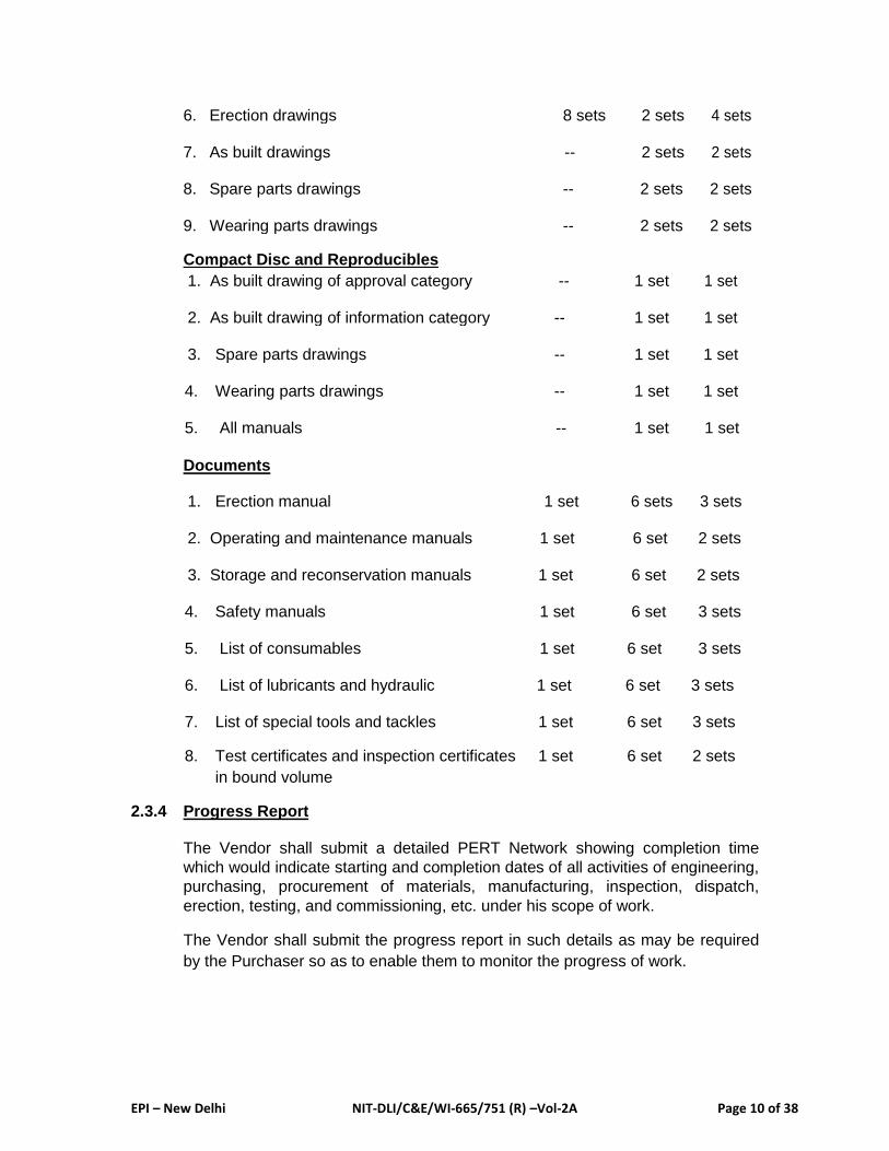
6. Erection drawings 8 sets 2 sets 4 sets
7. As built drawings -- 2 sets 2 sets
8. Spare parts drawings -- 2 sets 2 sets
9. Wearing parts drawings -- 2 sets 2 sets
Compact Disc and Reproducibles
1. As built drawing of approval category -- 1 set 1 set
2. As built drawing of information category -- 1 set 1 set
3. Spare parts drawings -- 1 set 1 set
4. Wearing parts drawings -- 1 set 1 set
5. All manuals -- 1 set 1 set
Documents
1. Erection manual 1 set 6 sets 3 sets
2. Operating and maintenance manuals 1 set 6 set 2 sets
3. Storage and reconservation manuals 1 set 6 set 2 sets
4. Safety manuals 1 set 6 set 3 sets
5. List of consumables 1 set 6 set 3 sets
6. List of lubricants and hydraulic 1 set 6 set 3 sets
7. List of special tools and tackles 1 set 6 set 3 sets
8. Test certificates and inspection certificates 1 set 6 set 2 sets
in bound volume
2.3.4 Progress Report
The Vendor shall submit a detailed PERT Network showing completion time
which would indicate starting and completion dates of all activities of engineering,
purchasing, procurement of materials, manufacturing, inspection, dispatch,
erection, testing, and commissioning, etc. under his scope of work.
The Vendor shall submit the progress report in such details as may be required
by the Purchaser so as to enable them to monitor the progress of work.

EPI – New Delhi NIT-DLI/C&E/WI-665/751 (R) –Vol-2A Page 11 of 38
The Vendor shall submit the progress report every month in the proforma
mutually discussed and agreed.
2.3.5 Coding Seheme
All drawings/documents/equipment/spare parts/shipments shall have a coded
number which shall be finalized with the successful tenderer. 2.3.6 Title Block of Drawing
Separate file is attached as soft copy. Hard copy is enclosed
3.0 PERFORMANCE GUARANTEE 3.1 General
On completion of erection of the plant units along-with utilities and auxiliaries by
respective package bidders as per approved drawings / documents as well as
detailed drawings, the successful bidder shall undertake preliminary Acceptance
Test (PAT) i.e. cold test, to prove that the unit has been supplied as per
agreement and after erection the unit is fit to be started up and commissioned.
The PAT shall be followed by commissioning (hot trials) to demonstrate that the
unit is fit for commercial production.
3.1.1 Preliminary Acceptance Test (PAT)
Cold tests shall be performed on the individual sub-assemblies of the unit and
shall be designed to conduct the systematic check of the components and of the
functional operation thereof.
Cold tests shall comprise idle, no-load tests. Cold tests shall be conducted by
the successful bidder under his sole responsibility. The employer will provide
skilled operating personnel during the cold test. A detailed programme of cold tests shall be drawn up by the successful bidder and shall be subject to the approval of the employer / consultant. Such
programme may be revised and adjusted as may be required by the employer during the test run.
Results of cold tests shall be recorded jointly by the successful bidder and the
employer.
On successful completion of preliminary acceptance tests, and liquidation of the
defects list, preliminary acceptance certificates shall be issued by the employer.
3.1.2 Successful Commissioning (Hot Trials)
After issue of preliminary acceptance certificates, the successful bidder shall
start-up and commission the unit in an integrated manner under his sole
responsibility.
EPI – New Delhi NIT-DLI/C&E/WI-665/751 (R) –Vol-2A Page 12 of 38
During the start-up and commissioning, the successful bidder shall perform the
required adaptation, adjustment and hot run the Plant & Equipment to
demonstrate its production capacity.
The employer shall, for the purpose of start- up and commissioning, provide
operating personnel as may be available with him for normal operation, who
shall work under the instructions and guidance of the successful bidder.
Start-up and commissioning of the unit shall be taken up only when material
handling system, electrical power system, inter-plant fluid system and auxiliaries
serving the unit as well as the preceding / succeeding plant units are under
normal operation and / or feed material is available. The successful bidder shall
rectify the defects observed during commissioning.
The quantities of starting material and facilities necessary for conducting the
commissioning shall be mutually determined by the successful bidder and employer
Commissioning of the unit shall be deemed to be successfully completed, after
ten (10) days of rated material is successfully transported , for the particular
circuit.
Results of start-up tests and commissioning shall be recorded jointly by the
successful bidder and the employer.
On successful completion of commissioning of the unit and its commencement
of commercial production as per above mentioned clause, commissioning
certificate shall be issued by the employer within 15 days.
The unit shall be taken over by the employer when: a) Commissioning certificate as per clause 08.01.02.008 has been issued
by the employer.
b) The successful bidder has submitted all final documents in compliance
with the provisions of this specification.
c) The successful bidder has supplied all consumables, change parts,
special tools and tackles and commissioning spares.
d) The successful bidder has met, to the satisfaction of the employer, all the
observation, if any, contained in the Preliminary Acceptance certificate. 3.1.3 Performance Guarantee Tests (PG)
After successful commissioning of the plant & equipment, the bidder shall offer
the plant for conducting performance guarantee tests as mutually agreed upon
between the employer and bidder.
EPI – New Delhi NIT-DLI/C&E/WI-665/751 (R) –Vol-2A Page 13 of 38
The bidder shall supervise and carry out the operation under their instruction
and guidance during performance guarantee tests and shall take full
responsibility of the operation. The employer will make available necessary
operating and maintenance personnel as per the agreed manning schedule as
well as the raw materials, utilities and services etc, as specified.
The bidder shall submit the scope, general preconditions, test procedures and
test evaluation methods which shall be finalised during tender discussion.
The performance tests for all plant equipment shall be carried out to satisfy all operating parameters as per the relevant clauses of the
Technical specification for the equipment under consideration.
Performance Guarantee Test
Sl Description Acceptable
Acceptable Liquidated Rejected
No with
Damages penalty
1.0 Wagon 20 tippling per hour - Not applicable Less than
Tippler 20 wagons
per hour
2.0 Yard As per rated - Not applicable Less than Machines capacity rated
Stacker – 1500tph capacity
Reclaimer-1500tph
3.0 Conveying As per rated - Not applicable Less than capacity capacity rated
capacity
4.0 Environment As specified in TS - Not applicable Not
Norms achieving
norms
The performance guarantee test shall be performed for each sub section
continuously for 10 days. Continuity of operation however, be limited by
availability of raw materials for unloading and stacking and availability of storing
capacity on delivering end. Wherever equipment in the sub section is of stand by
nature, each such equipment shall operate for at least 10 hours on load in the
period.
The performance guarantee test shall also be performed for the complete
system for 5 days on round the clock basis.
In case test is disrupted due to reasons attributable to employer, the same shall
EPI – New Delhi NIT-DLI/C&E/WI-665/751 (R) –Vol-2A Page 14 of 38
be repeated two more times attending to the reasons of the employer. If the PG test is
disturbed even after this, the PG test shall be on the basis of uninterrupted operation of system for 100 hours of total system, excluding the stoppages due to fault of the
bidders. However, there should not be any failure of the equipment supplied by Bidder between starts and finish of this time counting. If the operation stops due to failure of
any item supplied by bidder, the operating hours prior to such failure will not be counted.
In case some equipment can not be tested within the period of testing because of failure
of equipment or facility provided by others, the same will be accepted on the basis of
load test result for the limited period or no – load test result where load test could not be
performed at all.
The bidder shall prepare and submit a draft performance test procedure for each
equipment and system within 12 months of order. The final performance test procedure
will be prepared jointly by the employer / consulting engineers and the bidder based on
the draft performance test prepared by the bidder and various requirement indicated in
the contract specification and the order

EPI – New Delhi NIT-DLI/C&E/WI-665/751 (R) –Vol-2A Page 15 of 38
4.0 GENERAL SPECIFICATION ON QUALITY SYSTEM, INSPECTION & TEST OF PLANT & EQUIPMENT AT MANUFACTURER’S PREMISES
4.1 General
Inspection & testing of plant & equipment shall be carried out by
BSP/MECON/EPI at the works of successful tenderer during manufacturing
and/or on final product to ensure conformity of the same with the acceptable
criteria of technical specifications, approved drawings, manufacturing drawings
applicable national / international standards. 4.2 Quality System Requirements
The successful tenderer must recognise the importance of quality and follow
defined quality programme in all stages of manufacturing and quality control
activities of the product. Vendor / Contractor must define and implement the
tasks and control that will provide needed assurance, in case manufacturing of
product is sub-contracted either partly or fully and/ or for the procured from
vendors which are duly approved by the project authority.
BSP/MECON/EPI reserve the right to verify the quality programme of tenderer &
its vendors/sub- vendors to assure the effectiveness of the programme to meet
the intended and specified quality of the product. 4.3 Quality Assurance Plan (QAP)
4.3.1 The successful tenderer shall furnish Quality Assurance Plan (QAP) for
respective equipment after completion of detailed engineering and finalisation of
billing schedule / equipment identification number for Consultant’s approval at
least one month prior to start of manufacturing. 4.3.2 QAP shall be prepared & furnished by Vendor / Contractor for structural &
mechanical equipment, electrical equipment and refractory materials etc., QAPs
must be submitted in four (4) sets duly signed and stamped by tenderer for
BSP/MECON/EPI approval. 4.3.3 The successful tenderer shall indicate procurement source and furnish to
BSP/MECON/EPI, during the submission of QAP, copies of P.O., Sub-P.O., T.S.,
approved GA drawings/ data sheets & detailed manufacturing drawings, as
backup reference materials for scrutiny & final approved by BSP/MECON/EPI.
The submission & subsequent approval of QAPs shall be ensured to be
restricted to one round only. 4.3.4 Inspection and test requirements shall be decided with due consideration of
factors like safety, duty cycle, operating conditions, equipment life, environmental
conditions, place of installation and statutory regulations, as applicable, for a
particular equipment. Any, additional type or special tests or routine tests if found
necessary to establish the intended quality after detailed engineering then the
EPI – New Delhi NIT-DLI/C&E/WI-665/751 (R) –Vol-2A Page 16 of 38
same shall have to be incorporated in the QAP without any commercial
implication.
4.3.5 Detailed QAP shall be prepared by the successful tenderer in consultation with
their Sub-contractors / Manufacturers to avoid any complicacy later.
4.4 Calibration of Measuring Equipment
4.1 All the measuring equipment used for inspection & testing shall be calibrated and
appropriate accuracy class of measuring equipment shall be used. Calibration
standards used for calibration of measuring equipment shall be traceable to
national standards of National Physical Laboratory (NPL), New Delhi with
unbroken chains of comparison. 4.2 Valid calibration certificate for all measuring equipment used during inspection
and testing at manufacturer’s works, with traceability to national standards of
NPL/ NABL accredited laboratories shall be furnished prior to undertaking
inspection by BSP/MECON/EPI.
Calibration certificate shall also indicate reference no. of calibration standards
calibrated by NPL/NABL accredited laboratories and copies of such calibration
certificates of calibration standards shall be included in the complied dossiers of
inspection/test results.
4.5 Test Certificates and Documents
4.5.1 For each of the items being manufactured as per approved QAP, following test
certificates and documents, as applicable for each of the equipment, in requisite
copies including original, duly endorsed by the Manufacturer/successful tenderer
with appropriate linkage to project, purchase order and acceptance criteria etc
shall be submitted to Consultant/Purchaser.
i) Raw materials identification & physical and chemical test certificates for
all materials used in manufacture of the equipment (except IS: 2062-1999
Gr.A & IS: 210 –1993, FG-150).
ii) WPS, PQR & WPQ documents as per applicable code.
iii) Details of stage wise inspection & rectification records for fabricated
items, castings, forgings and machined articles.
iv) Control dimension chart with records of alignment, squareness etc.
v) Manufacturer’s material and performance/ relevant test certificates for all
bought-out items.
vi) Details of heart-treatment and stress relieving charts as per specification.
vii) Non-Destructive Test reports as per respective code.
EPI – New Delhi NIT-DLI/C&E/WI-665/751 (R) –Vol-2A Page 17 of 38
viii) Static/dynamic balancing certificate for rotating components/machines. ix) Hardness test certificate.
x) Pressure/Leakage Test Certificates.
xi) Performance Test Certificates for all characteristics.
xii) Routine / type / calibration / acceptance / special test (Type Tests etc)
certificates for electrical items.
xiii) Surface preparation and painting certificates.
xiv) Certificates from competent authority for the items coming under statutory
regulations. 4.5.2 Where physical and chemical test certificates of material are not available, the
successful tenderer/Sub-contractor shall arrange to have specimens and test
samples of the materials, tested in his own laboratory at his cost and submit the
copies of test results in requisite numbers to BSP/MECON/EPI for review.
Number of test samples against each heat/cast/lot or batch of materials, as
applicable shall be as per relevant Indian or International Standards. 4.5.3 Where facilities for testing do not exist in the successful tenderer/Sub-
contractor’s laboratories or in case of any dispute, samples and test pieces shall
be drawn by the successful tenderer/Sub-contractor in presence of
BSP/MECON/EPI and sealed sample shall be sent to any Govt. approved /NABL
accredited laboratory for necessary tests at former’s own cost. 4.5.4 The BSP/MECON/EPI shall have the right to be present and witness all tests
being carried out by the successful tenderer/Sub- contractor at their own
laboratory or approved laboratories. Also, the Inspection Agency shall reserve
the right to call for confirmatory test on samples, at his discretion.
4.6 Internal Inspection by Successful Tenderer/Manufacturer
4.6.1 Inspection and tests shall be carried out by Contractor/ Manufacturer in
accordance with approved drawing, T.S., P.O., and approved QAP. They shall
maintain records of each inspection and test carried out and signed documents
shall be submitted to Purchaser/ Consultant for verification. 4.6.2 The successful tenderer shall carry out their internal inspection & obtain
clearance from statutory bodies e.g. IBR, CCE, TAC, Weights & Measures,
safety, IE rules etc. prior to offering any equipment for BSP/MECON/EPI’s
inspection in accordance with approved QAP. 4.6.3 The successful tenderer/ Manufacturers shall identify all the inspected
equipment/component/raw materials & shall maintain the record of status of
EPI – New Delhi NIT-DLI/C&E/WI-665/751 (R) –Vol-2A Page 18 of 38
inspection viz. inspected & found acceptable, require rectification/rework,
rejected etc.
4.6.4 The successful tenderer shall establish and maintain procedures to ensure that
the product that does not confirm to specified requirements is prevented from
inadvertent use or installation. The description of non-conformity that has been
accepted subsequently by BSP/MECON/EPI by concession and/ or of repairs,
shall be recorded.
Repaired and reworked product shall be offered for re-inspection to
BSP/MECON/EPI along with records of corrective action taken.
4.7 Manufacturing and inspection schedule
All Vendors / contractors shall submit the schedule for manufacturing and
inspection indication equipment / components, sub- assembly/ assembly. Date of
approval of drawings / data sheets. Address of manufacturer with contact person and scheduled date of inspection. Such reports shall be submitted to respective
Consultant Inspecting Offices with a copy to Inspection Co-ordinating Office once in a month. These monthly reports shall state the planning for next three months.
Submission of first reports must commence one month prior to commencement
of manufacturing activities of the product. 4.8 Method of Undertaking Inspection & Testing by Consultant / Purchaser
4.8.1 Inspection call shall be given only on readiness of the equipment/ assembly/ sub-
assembly & after approval of all relevant drawings and QAP, In case equipment/
assembly/sub-assembly offered for inspection are found not ready, all the cost of
visit of Consultant’s engineer shall have to be borne by the successful tenderer.
If the equipment/assembly/sub-assembly after inspection found not acceptable,
require rework and involve Consultant’s re-inspection, all the cost of such re-
inspections shall also have to be borne by the successful tenderer. 4.8.2 Inspection call shall be floated to BSP/MECON/EPI, in the approved duly filled in,
with ten days clear margin, enclosing all documents like test Certificates, Internal
Inspection Reports, P.O., Sub-P.O., T.S., Approved QAP, approved GA
drawings/ data sheets and manufacturing drawings. Inspection calls without
above documents shall be treated as invalid and shall be ignored. The hard copy
of such documents must also accompany a CD (comprising computer readable
files) containing the identical documents. 4.8.3 The successful tenderer shall offer substantial quantities for economical
inspection consistent with the size of order. 4.8.4 On receipt of the Inspection call, pertaining to particular package / equipment/
item, QA & Inspection group of MECON, Ranchi (Overall co-ordinating office for
Inspection activities) shall organize inspection visit or will issue Inspection
assignment to other Consultant’s office (based on nearness to the vendor’s

EPI – New Delhi NIT-DLI/C&E/WI-665/751 (R) –Vol-2A Page 19 of 38
manufacturing works / relevant job expertise ). For further inspection pertaining to
the same package / equipment / item, successful tenderer may forward the
subsequent inspection calls to the respective Consultant’s offices (as identified
per initial assignment ), with a copy to QA & Inspection Section, Ranchi.
4.9 Obligations of Successful Tenderer 4.9.1 The successful tenderer shall provide all facilities and ensure full and free access
of the Inspection Engineer of BSP/MECON/EPI to their own or their Sub-Contractor’s premises at any time, during contract period, to facilitate him to carry out inspection & testing of the product during or after or after manufacture of the same.
4.9.2 The successful tenderer shall delegate a Representative / Co-ordinator to deal
with BSP/MECON/EPI on all inspection matters. Representative of successful
tenderer shall be present during all inspection at Sub-Contractor’s works. 4.9.3 The successful tenderer shall comply with instructions of BSP/MECON/EPI fully
and with promptitude. 4.9.4 The successful tenderer/ Sub-Contractor shall provide all instruments, tools,
necessary testing & other inspection facilities to BSP/MECON/EPI free of cost for
carrying out inspection. 4.9.5 The cost of testing welds by ultrasonic, radiographic and dye penetration tests
etc. in the fabrication workshop shall be borne by the successful tenderer. These
tests need to be witnessed by ASNT/ISNT Level-II qualified NDT personals. 4.9.6 The successful tenderer shall ensure that the equipment/ assembly/ component
of the plant and equipment required to be inspected, are not dismantled or
dispatched before inspection. 4.9.7 The successful tenderer shall not offer equipment for inspection in painted
condition unless otherwise agreed in writing by BSP/MECON/EPI. 4.9.8 The successful tenderer shall not offer equipment and materials once rejected by
the BSP/MECON/EPI, are not re-used in the manufacture of the plant and
equipment. Where parts rejected during inspection have been rectified as per
agreed procedures laid down in advance, such parts shall be segregated for
separate inspection and approval, before being used in the work.
4.10 Stamping and Issue of Inspection Documents
4.10.1 Inspection Memo:- For rejected items/ items, which do not conform to Technical
Specification in one or more quality characteristics requiring rectification / rework,
Inspection Memo shall be issued indicating therein the details of observation &
remarks. All the non-conformities with respect to specification of the product shall
be indicated in the Inspection Memo for further quality control by successful
tenderer.

EPI – New Delhi NIT-DLI/C&E/WI-665/751 (R) –Vol-2A Page 20 of 38
4.10.2 Inspection Certificate:- On satisfactory completion of final inspection & testing.
All accepted plant & equipment shall be stamped suitably and Inspection
Certificate shall be issued by the Consultant for the accepted items.
4.11 General Clause
4.11.1 Inspection & tests carried out by Consultant/Purchaser shall no absolve the
responsibility of the successful tenderer/ Manufacturer to provide acceptable
product as per the terms of contract nor shall it preclude subsequent rejection. 4.11.2 Purchaser/ Consultant reserve the right to inspect any product at any stage of
manufacturing beyond pre-identified stages & hold points of approved QAP.
4.12 Format
Performa for inspection of all equipment shall be as per EPI / EPI’s clients
requirement.
5.0 PAINTING
5.1 General
5.1.1 This specification covers the materials, tools, facilities and quality requirement for
surface preparation and painting of steel structures, equipment, piping, ducts,
chutes, wood work etc. 5.1.2 This is only a general guideline of the painting scheme to be followed by the
Tenderer, However, in case a specific painting procedure is stipulated in any
tendering specification, then this general guideline shall be superseded. Any
special case which may arise from time to time shall be dealt with individually on
the merit of each case. 5.1.3 The term “painting” referred herein covers rust preventive, fungus/insects
preventive and decorative coating along with surface protection of the following
area but not limited to the areas indicated below. i) Structural steel works ii) Mechanical equipment iii) Electrical equipment iv) Instrumentation and control equipment. v) Pipe work vi) Oxygen plant, etc.
5.1.4 Surfaces made of asbestos, aluminum, brass, bronze, galvanized steel, stainless
steel, cast iron and other corrosion resistant alloys and rubber/synthetic
polymer/fiber reinforcement plastic and buried pipe work are not required to be
painted unless specified except for aesthetic purposes or for identification bands,
wherever relevant.

EPI – New Delhi NIT-DLI/C&E/WI-665/751 (R) –Vol-2A Page 21 of 38
5.1.5 The complete paint system for any item includes the following basic activities: i) Proper surface preparation ii) Application of primer coats iii) Application of intermediate coats iv) Application of finished coats
All the above coats shall be of quality paint products and of approved make. The
scope of work shall also include supply of all paint materials as per specification
described herein.
5.1.6 If the contractor desires to adopt alternative paint system for any specific item for
an improvement or equivalent to the system specified here-in or as per
recommendations of paint manufacturer, may do so subject to purchaser’s
approval in advance.
5.2 Surface Preparation
5.2.1 Surface preparation required for paint application, shall be such as to clean the
surface thoroughly of any material which will be conducive to premature failure of
the paint substrates.
5.2.2 All surfaces shall be cleaned of loose substances, and foreign materials, such as
dirt, rust, scale, oil, grease, welding flux, etc. in order that the prime coat is rigidly
anchored to the virgin metal surface. The surface preparation shall confirm to
pictorial representation of surface quality grade of Swedish Standards Institution
SIS – 055900 or equivalent standards such as SSPC – VIS – 1.67 or DIN 55928
(Part 4) or BS 4232 or IS 1477 – 1971 (Part I).
5.2.3 The acceptable surface preparation quality /grade are described under each
paint system. The procedures include solvent cleaning. Hard tool cleaning, power
tool cleaning, blast cleaning, wood surface cleaning, flame cleaning and pickling.
The will ensure surface quality as required by the specific primer paint. For ready
reference surface preparation quality grade to be adopted in respect of SIS
055900 and DIN 55928 (Part – 4) is given in Annexure -01. 5.2.3.1 Solvent Cleaning
The surface shall be cleaned by wiping, immersion, spraying or vapour
contacting of a suitable solvent or washing with an emulsion or alkaline solution
to remove oil, grease, dirt, old paint, etc. Solvent cleaning shall not remove rust,
scales, mill scales or weld flux. Therefore, before application of paint, solvent
cleaning shall be followed by other cleaning procedures as stated in subsequent
clauses. 5.2.3.2 Hand Tool Cleaning
The surface shall be cleaned manually by vigorous wire brushing as per grade St
-2 quality of Swedish Standard Institution SIS 055900 and DIN 555928. This

EPI – New Delhi NIT-DLI/C&E/WI-665/751 (R) –Vol-2A Page 22 of 38
method effectively removes loosely adherent materials, but would not affect
residues of rust or mill scales that are intact are firmly adherent. Finally the
surface is to be cleaned with a vacuum cleaner or with clean compressed air or
with clean brush. After preparation the surface shall have a faint metallic shine.
The appearance shall correspond to the prints designated St-2.
5.2.3.3 Power Tool Cleaning The surface shall be cleaned by electric or pneumatic tools, such as brushes, sanding machines, disc abrasive grinder, rotary disc scaler etc, to St -3 quality. The tools shall be used carefully to prevent excessive roughening of surface and formation of ridges and burrs. This method will remove loosely adherent materials but would not affect residues of rust or mill scales that are firmly adherent and intact.
5.2.3.4 Blast Cleaning
The surface shall be cleaned by impingement of abrasive materials, such as graded sand at high velocity created by clean and dry compressed air blast as per the grade according to Swedish Standard Institution SIS 055900. This method will remove loosely adherent materials as well as adherent scales and mill scales. Prior to application of blast, heavy deposit of oil and grease are removed by solvent cleaning excessive surface scales are removed by hand tools or power tool cleaning. The extent of removal of adherent scales is varied, depending on the application and are defined by the surface quality grades Sa 1, Sa 2, Sa 2.5 and Sa 3 in the order of increasing cleanliness. The blast cleaning is not recommended for sheet metal work.
5.2.3.5 Flame Cleaning
The surface is cleaned by rapid heating by means of oxyacetylene flame to
loosen the adherent scales, followed immediately by wire brushing. This method
will remove loosely adherent materials as well as most of the adherent scales
and mill scales. In order to minimize or prevent distortion flame cutting shall not
be used on members having thickness of 6 mm and lower. 5.2.3.6 Pickling
In this method the surface is cleaned of mill scales, rust or rust scales by
chemical reaction or electrolysis or both.
5.3 Paint Application
5.3.1 Paints
5.3.1.1 Paint shall be applied in accordance with paint manufacturer’s recommendations.
The work shall generally follow IS 1477 – 1971 (Part II) for jobs carried out in
India and SSPC-PA-1 or DIN 55928 of equivalent for jobs carried out outside
India.
EPI – New Delhi NIT-DLI/C&E/WI-665/751 (R) –Vol-2A Page 23 of 38
5.3.1.2 General compatibility between primer and finishing paints shall be established by
the paint manufacturer supplying the paints. 5.3.1.3 In the event of conflict between this general procedure on painting and the paint
manufacturer’s specification, the same shall be immediately brought to the notice
of the Purchaser. Generally in cases of such conflicts, Manufacturer’s
specifications / recommendations shall prevail. 5.3.1.4 Before buying the paint in bulk, it is recommended to obtain sample of paint and
establish “Control Area of Painting”. On Control Area, surface preparation and
painting shall be carried out. 5.3.1.5 If required, samples of paint shall be tested in laboratories to establish quality of
paint with respect to:
(i) Viscosity (ii) Adhesion/Bond of paint in steel surfaces. (iii) Adhesion/Simulated salt spray test. (iv) Chemical analysis (percentage of solids by weight). (v) Normal wear resistance as encountered during handling & erection. (vi) Resistance against exposure to acid fumes, etc.
5.3.1.6 Whole quantity of paint for a particular system of paint shall be obtained from the
same manufacturer. 5.3.1.7 The main Contractor shall be responsible for supply of paints and this
responsibility shall not be passed on to the sub-contractor. 5.3.1.8 The painting material as delivered to the Contractor, must be in the
manufacturer’s original container bearing thereon manufacturer’s name brand
and description. Paint/Painting material in containers without labels or with
illegible labels shall be rejected, removed from the area and shall not be used. 5.3.1.9 Thinners wherever used shall be those recommended by the paint manufacturers
and shall be obtained in containers with manufacturer’s name and brand name of
thinner legibly printed, failing which the thinner is liable to be rejected and shall
not be used. 5.3.1.10 All paint containers shall be clearly labeled to show the paint identification, date
of manufacture, batch number, special instruction, shelf life etc. The container
shall be opened only at the time of use. 5.3.1.11 All paints shall be stored in accordance with the requirements of laid down
procedure by the paint manufacturer. 5.3.1.12 All ingredients in a paint container shall be thoroughly mixed to break-up lumps
and disperse pigments before use and during application to maintain
homogeneity.
EPI – New Delhi NIT-DLI/C&E/WI-665/751 (R) –Vol-2A Page 24 of 38
5.3.1.13 The proposed make, quality and shade of the paint shall have the approval of the
client. 5.3.1.14 The colour code of the finishing paint to be followed shall be intimated to the
successful Tenderer after finalisation of order. The undercoat shall have different
tint to distinguish the same from the finishing coat. 5.3.1.15 The Contractor shall furnish paint manufacturer’s test report or technical data
sheet pertaining to the paint selected. The data sheet shall indicate among other
things the relevant standards, if any, composition in weight percent of pigments,
vehicles, additives, drying time, viscosity, spreading rate, flash point, method of
application, quality of surface preparation required, corrosion resistance
properties and colour shades available. 5.3.1.16 For details of paint materials refer Annexure -02.
5.3.2 General
5.3.2.1 Each coat of paint shall be continuous, free of pores and of even film thickness
without thin spots. 5.3.2.2 Each coat of paint shall be sufficiently dry before application of next coat. 5.3.2.3 Paint shall be applied at manufacturer’s recommended rates. The number of
coats shall be such that the minimum dry film thickness specified is achieved.
The dry film thickness of painted surfaces shall be checked with ELCOMETER of
measuring gauges to ensure application of specified DFT. 5.3.2.4 Zinc rich primer paints which have been exposed several months before finishing
coat is applied shall be washed down thoroughly to remove soluble zinc salt
deposits. 5.3.2.5 The machine finished surfaces shall be coated with white lead and tallow before
shipment or before being put out into the open air. 5.3.2.6 Areas which become inaccessible after assemble shall be painted before
assembly (after obtaining painting clearance from the inspecting authority) after
requisite surface cleaning as specified. 5.3.2.7 Paint shall not be applied when the ambient temperature is 5 deg C and below or
45 deg C and above. Also paint shall not be applied in rain, wind, fog or at
relative humidity of 80% and above unless the manufacturer’s recommendations
permit. Applications of paint shall be only be spraying or brushing as per IS 486 –
1983 and IS 487 -1985. 5.3.2.8 Primer paint shall be applied not later than 2 -3 hours after preparation of
surface, unless specified otherwise.

EPI – New Delhi NIT-DLI/C&E/WI-665/751 (R) –Vol-2A Page 25 of 38
5.3.2.9 Edges, corners, crevices, depressions, joints and welds shall receive special
attention to ensure that they receive painting coats of the required thickness. 5.3.2.10 Surfaces which cannot be painted but require protection shall be given a coat of
rust inhibitive grease according to IS 958 – 1975 or solvent deposited compound
according to IS 1153 – 1975 or IS 1674 – 1960. 5.3.2.11 Surfaces in contact during shop assembly shall not be painted. Surfaces which
will be inaccessible after assembly shall receive minimum two coats of specified
primer. 5.3.2.12 Surfaces to be in contact with wood, brick or other masonry shall be given one
shop- coat of the specified primer.
5.3.3 Site/Field Painting 5.3.3.1 Wherever shop primer painting is scratched, abraded or damaged, the surface
shall be thoroughly cleaned using emery paper and power driven wire brush wherever warranted, and touched up with corresponding primer. Touching up
paint shall be matched and blended to eliminate conspicuous marks. 5.3.3.2 If more than 50% of the painted surface of an item requires repair, the entire item
shall be mechanically cleaned and new primer coats shall be applied followed by
intermediate and finishing coats as per painting specification. 5.3.3.3 All field welded areas on shop painted items shall be mechanically cleaned
(including the weld area proper, adjacent areas contaminated by weld spatter or
fumes and areas where existing primer paint is burnt). Subsequently, new primer
and finishing coats of paint shall be applied as per painting specification. 5.3.3.4 The first coat of finish paint at site shall be applied preferable within three months
of the shop paint.
5.3.4 Structural
5.3.4.1 All fabricated steel structure, fabricated steel pipes, etc. shall have a minimum of
two coats of primer paint before dispatch to site. 5.3.4.2 Parts of steel structures embedded in concrete shall be given a protective coat of
Portland cement slurry immediately after fabrication and after surfaces of this
part is thoroughly cleaned from grease, rust mill scales, etc. No paint shall be
applied on this part. 5.3.4.3 All structures shall receive appropriate number of primer and finishing coats in
order to achieve overall DFT as per design drawings/ specification.
5.3.5 Hot Surfaces
5.3.5.1 Total DFT for heat resistant paints should no exceed 100 – 120 microns,
otherwise flaking occurs (as per paint manufacturer’s recommendations).
EPI – New Delhi NIT-DLI/C&E/WI-665/751 (R) –Vol-2A Page 26 of 38
5.3.5.2 Heat resistant paints should be applied by brush. 5.3.5.3 Primer coat should not be applied on the surfaces having temperature condition
more that 120 deg C.
5.4 Painting Schemes
For a complete painting scheme of any item being printed, all types of paints are
to be procured from the same manufacturer as approved by the purchaser.
5.4.1 Legend SP - Surface preparation quality as per SIS standard 2P1 - Two (2) coats of Primer paint type P1 1I1 - One (1) coats of Intermediate paint type I1 2F1 - Two (2) coats of Finish paint type F1 DFT - Dry Film Thickness in microns developed
CRT - Clean and Retouch
Type of paint products like P1 to P9, I1 to 14 and F1 to F10 have been specified
under Annexure-02.
5.4.2 The painting scheme to be followed for various structure/equipment exposed to
different condition is briefly given in Annexure-03 for guidance to the tenderer. 5.4.3 The colour code for different applications are indicated in Annexure-04.
Wherever colour codes are not specified, the same is to be mutually agreed
between the Purchaser and Contractor.
5.5 Guarantee
5.5.1 The Contractor shall guarantee that the physical and chemical properties of the
paint materials conform with the specification of paint products. 5.5.2 The Contractor shall submit internal test reports from paint manufacturers
regarding the quality of paint whenever asked by the BSP/MECON/EPI. 5.5.3 Guarantee period shall commence from the date of completion of finishing coat
of paint. The guarantee period will be indicated depending on the type of surface
preparation and system of painting. To fulfill this obligations the Contractor may
obtain from the painting manufacturer, guarantee for the performance of
paint/painted surfaces.

EPI – New Delhi NIT-DLI/C&E/WI-665/751 (R) –Vol-2A Page 27 of 38
Annexure- 01
Surface Preparation Grade
Sl Surface Preparation Swedish Std DIN Std. Din
No. SIS 055900 55928 (Part 4)
1 Blast cleaning to white metal Sa 3 Sa 3 Removal of all visible rusts, mill-scales, paint
and foreign matters.
2 Blast cleaning to near white metal: Sa 2.5 Sa 2.5 95% of any section of surface area is free
from all rusts, mill-scales and visible residues.
3 Blast cleaning to commercial quality: Sa 2 Sa 2 At least 2/3 of any section of the surface area
is free from all rusts, mill-scales and visible
residues.
4 Brush-off blast cleaning: Sa 1 Sa 1 Removal of all loose mill-scales, rust and
foreign matters etc.
5 Power tool cleaning: St 3 St 3 Very thorough scrapping and wire brushing to
remove loose mill-scale, rust and foreign
matters to have pronounced metallic shine.
6 Hand tool cleaning: St 2 St 2 Removal by hand brushing of loose mill-
scale, loose rust and foreign matters.
EPI – New Delhi NIT-DLI/C&E/WI-665/751 (R) –Vol-2A Page 28 of 38
Annexure - 02 PAINT MATERIALS
1. PRIMER PAINTS (P)
Primer paint products shall be applied only on dry and clean surfaces.
01.1 Primer Paint –P1 (Phenolic – Alkyd Based)
A single pack air drying phenolic modified alkyd composition with zinc phosphate
as a primer paint conforming generally to IS : 2074.
Air drying time -
Dry film thickness (DFT)/
Coat Temperature resistance
About 60 minutes (touch dry) - Overnight (hard dry) - 40 microns (min)
- Upto 1000C dry heat
EPI – New Delhi NIT-DLI/C&E/WI-665/751 (R) –Vol-2A Page 29 of 38
01.02 Primer Paint – P2 (Chlororubber Based)
A single pack air drying high build chlorinated rubber based zinc phosphate
primer.
Percent chlororubber - 20 to 22 (% Chlorine above 65% in
Chlororubber)
Air drying time - About 15 minutes (touch dry)
- Overnight (hard dry)
DFT/ Coat - 50 microns (min)
Temperature resistance - Up to 650 C dry heat
01.03 Primer Paint – P3 (PVC Copolymer Alkyd Based)
Polyvinyl chloride (PVC) - Alkyd zinc phosphate – redoxide
Based primer
Ratio - PVC copolymer + alkyd reisn (1.1)
Pigments - Zinc phosphate & Fillers
Air drying time - 24 hours
DFT/Coat - 80 microns
Temperature - Upto 800 C dry heat
01.04 Primer Paint – P4 (Epoxy Based)

EPI – New Delhi NIT-DLI/C&E/WI-665/751 (R) –Vol-2A Page 30 of 38
A two pack air drying Epoxy polyamide resin based red oxide – zinc phosphate
primer.
Epoxy content (% wt.) - 15 to 18
Air drying time - About 30 minutes (touch dry)
- overnight (hard dry)
DFT/Coat - 30 microns (min)
Temperature resistance - Upto 1200C dry heat
01.5 Primer Paint – P5 (Epoxy Based)
A two pack air drying Epoxy polyamide with zinc dust of at least 92% zinc dust on
the dry film
Epoxy content (% wt.) - 8 to 10
Air drying time - Less than 10 minutes (touch dry)
Less than 2 hours (hard dry)
DFT/Coat - 40 microns (min)
Temperature - Upto 3000C dry heat
01.6 Primer Paint – P6 (Poly – Vinyl Butyral Resin Based)
A two pack air drying polyvinyl butyral resin based wash primer with rust
inhibitive pigments.
Air drying time - 5 to 7 minutes (touch dry)
- 2 hours (hard dry)
DFT/Coat - 8 microns
Temperature resistance - Upto 650C dry heat
Application for - Galvanised iron, aluminium, light alloys etc. on which the adhesion of
conventional paints are poor.
01.07 Primer Paint – P7 (Ethyl Zinc Silicate, EZS Based).
A two pack heavy duty zinc dust rich silicate primer which protects the surface
with just a single coat.
Total solids (3 wt) - 84 +/- 2
EPI – New Delhi NIT-DLI/C&E/WI-665/751 (R) –Vol-2A Page 31 of 38
Density (g / cc) - 3. 07 +/- 0.05 Air drying time - To top coat 16 hours DFT / Coat - 60 microns
Temperature resistance - Upto 450 deg C dry heat
01.08 Primer Paint – P8 (high Build Coal Tar Epoxy)
A two pack cold cured H. B. epoxy coal tar coating –no primer is required.
Mixing ratio - Base: Hardener (4:1 by vol.) Air drying time - 48 hours (hard dry)
Full cure 7 days
DFT / Coat - 100 microns
01.09 Wood Varnish –P9
Treated oil based primer pigmented with suitable pigments:
Air drying time - 16 hours for application of top coat.
Coverage - 10 to 14 sq. m/litre
2. INTERMEDIATE PAINTS (I)
These paints shall be applied over primer coats as an intermediate layer to
provide weather proof seal of primer coats.
02.1 Intermediate Paint-II (Phenolic alkyd based)
A single pack high build phenolic based paint with micaceous iron oxide (M 10).
Air Drying Time - 4 to 6 hours (touch dry) 2 days (hard dry)
DFT / Coat - 75 microns (min) Temperature resistance - Upto 100 deg C dry heat
Compatible with - Primer P1
02.02 Intermediate Paint -12 (Chlororubber based)
A single pack air drying high build chloro based paint with MIO.
Air Drying Time - 15 minutes (touch dry) - 24 hours (hard dry) DFT/Coat - 70 microns (min) Temperature resistance - Upto 65 deg C dry heat
Compatible with - Primer P2, P3 & P4
02.03 Intermediate Paint -13 (PVC – Alkyd Based)
EPI – New Delhi NIT-DLI/C&E/WI-665/751 (R) –Vol-2A Page 32 of 38
PVC Coploymer - Resin 1 : 1 Pigments - Micaceous iron oxide (MIO) DFT/Coat - 80 microns Temperature resistance - Upto 80 deg C dry heat
Compatible with - Primer P2 & P3
02.4 Intermediate Paint -14
A two pack air drying high build epoxy resin based paint with MIO.
Air drying time - 6 to 8 hours (touch dry) - 7 days (full cure) DFT / Coat - 100 microns
Temperature - Up to 1800C dry heat
Compatible with - Primer P4 & P5
3. FINISH PAINTS (F)
Finish paint costs shall be applied over primer coats and intermediate coats after
proper cleaning and touch up of primed surface.
03.1 Finish Paint – F1
A single pack air drying high gloss phenolic alkyd modified synthetic enamel
paint suitably pigmented.
Air drying time - 3 to 4 hours (touch dry)
- 24 hours (hard dry)
DFT/Coat - 25 microns (min)
Temperature - Upto 1000C dry heat
Compatible with - Primer P1 Intermediate I1
Colour - Generally all shades
03.02 Finish Paint –F2
A single pack air drying polyurethane enamel of high gloss and hard finish
suitably pigmented.
Air drying time - 2 to 2 ½ hours (touch dry)
- 6 hours (hard dry)
DFT/Coat - 30 microns (min)
Temperature resistance - Upto 1000C dry heat

EPI – New Delhi NIT-DLI/C&E/WI-665/751 (R) –Vol-2A Page 33 of 38
Compatible with - Primer P1 & P8 and Intermediate I1
Colour - Generally all shades
03.03 Finish Paint – F3
A two pack air drying bituminous aluminum paint.
Air drying time - 1 to 2 hours (touch dry)
- 21 hours (hard dry)
DFT/Coat - 25 microns (min)
Temperature resistance - Upto 1000C dry heat
Compatible with - Primer P1 and Intermediate I1
Colour - Bright metallic
03.04 Finish Paint – F4
A ready mixed oil –alkyd based synthetic enamel paint of high gloss and hard
wearing properties.
Air drying time - 6 to 8 hours
Coverage - 14 to 16 Sq. m/litre
Temperature resistance - Upto 600C dry heat
Compatible with - P8
Colour - Generally all shades
03.5 Finish Paint –F5
A single pack air drying plasticized chlororubber paint suitably pigmented.
Air drying time - 30 minutes (touch dry)
- 24 hours (hard dry)
DFT/Coat - 35 microns (min)
Temperature resistance - Primer 650C dry heat
Compatible with - Primer P2 & P3,
Intermediate I2 & I3
Colour - Nearly all shades except few.
EPI – New Delhi NIT-DLI/C&E/WI-665/751 (R) –Vol-2A Page 34 of 38
03.6 Finish Paint – F6
A PVC - Copolymer alkyd based enamel.
Density - 1.17 ± 0.05
Total solids (1 wt) - 55 ± 2
DFT/Coat - 40 microns
Compatible with - P2 and P3
03.07 Finish Paint – F7
A two pack air drying epoxy polyamide enamel suitably pigmented.
Air drying time - 2 to 3 hours (touch dry)
- 7 days (full cure)
DFT/Coat - 40 microns (min)
Temperature resistance - Up to 1300C dry heat
Compatible with - Primer P4 & P5,
Intermediate 14
Colour - Generally all shades.
03.8 Finish Paint – F8
A single pack synthetic rubber based aluminum paint.
Air drying time - 2 hours (touch dry)
- 24 hours (hard dry)
DFT/Coat - 25 microns (min)
Temperature resistance - Upto 2000C dry heat
Compatible with - No Primer paint except primer P6 is applicable in case of non- ferrous
substrate.
Colour - Smooth aluminium.
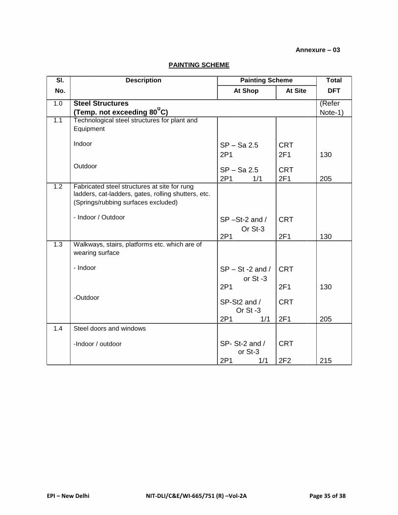
EPI – New Delhi NIT-DLI/C&E/WI-665/751 (R) –Vol-2A Page 35 of 38
Annexure – 03
PAINTING SCHEME
Sl. Description Painting Scheme Total
No.
DFT At Shop At Site
1.0 Steel Structures (Refer
(Temp. not exceeding 800C) Note-1)
1.1 Technological steel structures for plant and
Equipment
Indoor SP – Sa 2.5 CRT
130 2P1 2F1
Outdoor SP – Sa 2.5 CRT
205 2P1 1/1 2F1 1.2 Fabricated steel structures at site for rung
ladders, cat-ladders, gates, rolling shutters, etc.
(Springs/rubbing surfaces excluded)
- Indoor / Outdoor SP –St-2 and / CRT
2P1
Or St-3 2F1 130
1.3 Walkways, stairs, platforms etc. which are of
wearing surface
- Indoor SP – St -2 and / CRT
2P1
or St -3 2F1 130
-Outdoor SP-St2 and / CRT
Or St -3
2F1 205 2P1 1/1
1.4 Steel doors and windows
-Indoor / outdoor SP- St-2 and / CRT or St-3
2F2 215 2P1 1/1
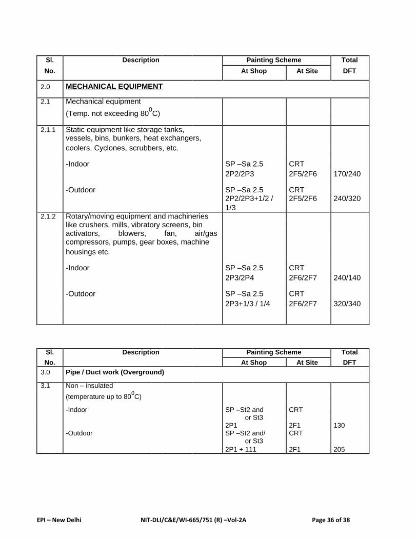
EPI – New Delhi NIT-DLI/C&E/WI-665/751 (R) –Vol-2A Page 36 of 38
Sl. Description Painting Scheme Total
No.
DFT At Shop At Site
2.0 MECHANICAL EQUIPMENT
2.1 Mechanical equipment
(Temp. not exceeding 800C)
2.1.1 Static equipment like storage tanks,
vessels, bins, bunkers, heat exchangers,
coolers, Cyclones, scrubbers, etc.
-Indoor SP –Sa 2.5 CRT
170/240 2P2/2P3 2F5/2F6
-Outdoor SP –Sa 2.5 CRT 240/320 2P2/2P3+1/2 / 2F5/2F6
1/3 2.1.2 Rotary/moving equipment and machineries
like crushers, mills, vibratory screens, bin
activators, blowers, fan, air/gas
compressors, pumps, gear boxes, machine
housings etc.
-Indoor SP –Sa 2.5 CRT
240/140 2P3/2P4 2F6/2F7
-Outdoor SP –Sa 2.5 CRT
320/340 2P3+1/3 / 1/4 2F6/2F7
Sl. Description Painting Scheme Total
No.
DFT At Shop At Site
3.0 Pipe / Duct work (Overground)
3.1 Non – insulated
(temperature up to 800C)
-Indoor SP –St2 and CRT or St3
2P1 2F1 130 -Outdoor SP –St2 and/ CRT
or St3
2P1 + 111 2F1 205
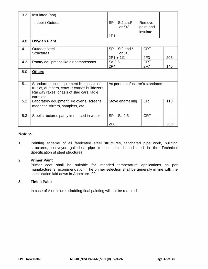
EPI – New Delhi NIT-DLI/C&E/WI-665/751 (R) –Vol-2A Page 37 of 38
Notes:-
1. Painting scheme of all fabricated steel structures, fabricated pipe work, building
structures, conveyor galleries, pipe trestles etc. is indicated in the Technical
Specification of steel structures. 2. Primer Paint
Primer coat shall be suitable for intended temperature applications as per
manufacturer’s recommendation. The primer selection shall be generally in line with the
specification laid down in Annexure -02. 3. Finish Paint
In case of Aluminiums cladding final painting will not be required.
3.2 Insulated (hot)
-Indoor / Outdoor SP – St2 and/ Remove or St3 paint and
1P1
insulate
4.0 Oxygen Plant
4.1 Outdoor steel SP – St2 and / CRT
Structures or St3
2P1 + 1I1 2F3 205 4.2 Rotary equipment like air compressors Sa 2.5 CRT
2P4 2F7 140
5.0 Others
5.1 Standard mobile equipment like chasis of As per manufacturer’s standards
trucks, dumpers, crawler cranes bulldozers,
Railway rakes, chasis of slag cars, ladle
cars, etc. 5.2 Laboratory equipment like ovens, screens, Stove enamelling CRT 110
magnetic stirrers, samplers, etc.
5.3 Steel structures partly immersed in water SP – Sa 2.5 CRT
2P8 200

EPI – New Delhi NIT-DLI/C&E/WI-665/751 (R) –Vol-2A Page 38 of 38
6.0 LIST OF APPROVED VENDORS/MAKES:
All the items to be supplied from enclosed approved vendors/ makes list of BSP /
MECON.
Please Refer : 1. Appendix - 6 (List of approved Sub-contractors / Vendors
2. Preferred makes - Chapter – 13 of GTS (GS-13)

APPENDIX – 6
LIST OF APPROVED SUB-CONTRACTORS / VENDORS
1.0 The following Sub-Contractors / Vendors are approved for carrying out the item of the Facilities indicated against each of them. Where more than one Sub- Contractor / Vendor is listed, the Contractor is free to choose between them, but it must notify the Employer of its choice well in advance time prior to appointing any selected Sub-Contractor / Vendor. In accordance with the Sub-Clause 19.1 of GCC, the Contractor is free to submit proposals for Sub- Contractors / Vendor for additional items from time to time. No Sub -Contractors / Vendors shall be placed with any such Sub-Contractors / Vendors for additional items until the Sub-Contractors / Vendors have been approved in writing by the Employer and their name have been added to this list of approved Sub-Contractors / Vendors.
• ELECTRICAL
Sl.No. Item Description Preferred Makes
1. HV EQUIPMENTS
1 220 KV & 132 KV Power BHEL, TELK, CGL, EMCO, AREVA, ABB,
Transformers up to 160 SIEMENS
MVA
2 33 KV, 11KV, 6.6KV Oil CGL, AREVA, Transformers & Rectifiers Ltd,
filled / Dry type, KEC, Intra Vidyut, Kanohar, VoltAmp, Bharat
distribution / Rectifier Bijlee, Andrew Yule, BHEL, EMCO, ABB,
Transformers SIEMENS
3 33 KV, 11KV, 6.6KV Oil CGL, EMCO, AREVA, BHEL, ABB
Filled Furnace
Transformers
4 220 KV and 132 KV SF6 ABB, CGL, SIEMENS, AREVA
Circuit Breakers
5 33 KV, 22 KV, 11 KV, 6.6 SIEMENS, BHEL, CGL, Schneider, AREVA,
KV Vacuum Circuit ABB, Jyoti (Jyoti -upto 11 KV only)
Breakers
6 6.6 KV, 11 KV Vacuum BHEL, AREVA, SIEMENS, Andrew Yule, Jyoti,
Contactors CGL
7 220 KV and 132 KV ABB, TELK, BHEL, CGL, AREVA
Current Transformer (CT)
8 33 KV, 22 KV, 11 KV, 6.6 Pragati, Instrans, Prayog, Intravidyut, Insutech
KV Current Transformer Industries, ABB .
(CT)
List of approved vendors
Page 1of 1

9 220 KV and 132 KV ABB, TELK, BHEL, CGL, AREVA
Voltage Transformer (PT)
10 33 KV, 22 KV, 11 KV, 6.6 ABB, Pragati, Prayog, Intravidyut, Jyoti KV Voltage Transformer
(PT)
11 220 KV and 132 KV AREVA, ABB, CGL, BHEL Capacitance Voltage
Transformer (CVT)
12 220 KV and 132 KV OBLUM, Elpro, AREVA, CGL
Lightning Arrestor (LA)
13 220 KV and 132 KV S&S Pondicherry, Elpro, WS-Insulators, ABB,
Isolators AREVA, CGL
14 33 KV, 11KV, 6.6KV A-Bond Strands, Drescher & Panicker, ABB, Isolator, Load Break SIEMENS, CGL
Switch
15 11 KV Air-Break Switch Pactil & Panchkari, Kayal & Co.
16 220 KV and 132 KV BHEL, CGL, AREVA, TELK. The Transformer
Condenser Bushings manufacturers may give their own / any other
make with QAP. 17 33 KV, 11KV and 6.6 KV ABB, Unistar(Universal Cables), BHEL, Meher
Capacitors (Bangalore)
18 33 KV, 11 KV and 6.6 KV OBLUM, Elpro, WS-Insulators, Toshiba,
Surge Suppressors SIEMENS
19 33 KV, 22 KV, 11 KV, Raychem, CCI, 3M, M-Seal (M-Seal for 6.6 KV) 6.6KV Cable Jointing Kits
(Heat Shrinkable Type) 20 Battery Chargers Chhabi Electricals, Standard, Hi-rect, Sherene
Electro Control, Amara Raja
21 Lead Acid Station Battery Exide, AMCO, Amara Raja
22 Electronic Energy Meters SEMS, L&T, SATEC, CONZERVE, Dukati, ABB,
(Trivector / KWH) SIEMENS, AREVA, Schneider
23 Protection and Auxiliary ABB, SIEMENS, L&T, AREVA, Schneider
Relays
24 Recorders (Chartless Chino, Yokogawa India Ltd, Okhura, Fuji, type) Eurotherm (Chessel), Tata Honeywell, Hioki,
Fluke, ABB, Pyrotech (Udaipur).
25 Annunciators Minilec, SPA, Procon, Yashmun,
List of approved vendors
Page 2of 2

Pyrotech (Udaipur)
26 Panel /Indicating IMP, AE, MECO, L&T, Motwani,
meters Conzerve 27 LT Air Circuit Breakers L&T, SIEMENS, Schneider, ABB, GE Power
Control
28 EHT/HT Insulators
1.Porcelain insulator WS-Insulators, Jayashree, BHEL, A-
Bond Strand, S&S, AREVA, Oblum
2. Epoxy insulator A-Bond Strand, Power Cam Electrical Pvt. Ltd., Baroda Bushings, S & C Electric Co.(America),
RISHO KOGYO CO. LTD (Japan)
29 HT HRC Fuses S&S, GE Power Control, Busmann,
SIEMENS, ABB, Drescher Paniker
30 HV / LV Bus Duct Best & Crompton, ECC (Kolkatta), Star Drive (Chennai), Enpro (Chennai), Advance Power Control (Advance Power Control only for LV Bus
Duct)
2. LV Equipments
31 Moulded Case Circuit Schneider (CG & MG), L&T, Andrew
Breaker (MCCB) Yule, ABB, SIEMENS, BCH(BIL), GE POWER
CONTROL, MOELLER 32 Motor Protection Circuit Schneider (TELEMECANIQUE), L&T, ABB,
Breakers. (MPCB) SIEMENS, GE POWER CONTROL, MOELLER,
Rockwell Automation
33 Miniature Circuit Breaker.
SIEMENS, L&T, GE POWER, CONTROL,
SCHNEIDER (PROTEC / MG), STANDARD, (MCB)
INDOASIAN, HAVELLS, MDS (LEGRAND), ABB
34
Earth Leakage Circuit GE POWER CONTROL, STANDARD,
Breaker HAVELLS, ABB, SIEMENS, SCHNEIDER 35 Switch, fuse Unit / Fuse GE POWER CONTROL, L&T, SIEMENS,
Disconnector BASANT PRAN & CO.
(Fuse Switch Unit), Air HAVELLS, STANDARD, INDOASIAN,
Break switch CONTROL & SWITCH GEAR, ANCHOR
HRC fuse for LT
GE POWERCONTROL, L&T, SIEMENS,
36 BHARAT LINDER, INDO ASIAN, HAVELLS, application STANDARD, BUSSMAN, CONTROL & SWITCH
GEAR, ABB 37 Power Contactor
for Crane / Mill
Duty Operation
List of approved vendors
Page 3of 3
1. Box Type (AC/DC) ABB, SIEMENS, SCHNEIDER
(TELEMECANIQUE), L&T, MOELLER, GE
POWER CONTROL, ROCKWELL
AUTOMATION
2. Vacuum Contactor SIEMENS, L&T, MOELLER, ABB,
SCHNEIDER (TELEMECANIQUE)
3. AC/DC Power BCH (BIL), BHEL, L&T,
Contactor-Clapper SCHNEIDER(TELEMECANIQUE),
Type/ Bar Mounted - GE (USA), ABB, Lenoir Elec
Mill Duty / Crane Duty (France), Microelectrica Scientifica (Italy)
38 Power contactor for ABB, SIEMENS, SCHNEIDER,
General Purpose & L&T, Rockwell Automation, Andrew Yule, Continuous Duty SCHNEIDER (C.G.), BCH (BIL), MOELLER,
operation CONTROL & SWITCHGEAR
39 Over Load Relays
1. Thermal (Bimetallic) BCH (BIL), L&T, SEIMENS, SCHNEIDER
(TELEMECANIQUE), Andrew Yule,
SCHNEIDER (C.G.), Rockwell Automation 2. Electronic Over Load SIEMENS, L&T, ROCKWELL AUTOMATION,
relays MOELLER, BCH, SCHNEIDER-SAMWHA
3. Electro magnetic BCH, KILBURN, BHEL, Schneider
Over Load relay (Telemecanique)
40 Aux.Contractors / Control OEN, L&T, SCHNEIDER, ANDREW YULE, GE
Relays POWER CONTROL, BCH (BIL), EASUN
REROLLE, JYOTI, Rockwell Automation.
41 Time Delay Relay
1. Electro Pneumatic
BCH (BIL), SCHNEIDER (TELEMECANIQUE), BHEL, ESAUN REROLLE
2. Electronic Timer SELECTRON, SIEMENS, BCH (BIL), ALSTOM,
L&T, ROCKWELL AUTOMATION, IFM,
SCHNEIDER (TELEMECANIQUE)
3. Time switches L&T, GE POWER CONTROL, EAPL, INDO
ASIAN, Schneider (MG)
42 Master Controller EPCC, INDUSTRIAL SYNDICATE, STROM
KRAFT, SCHEIDER, (SQUARE D),
SCHNEIDER (TELEMECANIQUE)
43 Limit Switches
1. Crane & Heavy duty EPCC, SCHNEIDER, INDUSTRIAL
Application SYNIDICATE, STROM KRAFT, Jai Balaji 2. Micro & Other ESSEN DEINKI, L&T, BCH(BIL), SIEMENS,
Actuating Type SCHNEIDER (TELEMECANIQUE), JAI BALIJI
44 Resistance Boxes EPCC, RSI, KINGS, TALSON
List of approved vendors
Page 4of 4

(Fechral Edge Wound)
45 Electromagnetic DC EPCC, BCH (BIL), INDUSTRIAL SYNDICATE
Brake assembly
3. Power Control and Electronics Items
46 Thyristor Converters
1. General Purpose up to BHEL, SIEMENS, SSD Drives, ABB, NELCO,
1 KA ABIL, Converteam.
2.Critical application up to BHEL, Siemens, ABB.
1KA
3. 1 KA to 10 KA BHEL, Siemens, ABB.
4. Main drives, more than BHEL, Siemens, ABB.
10 KA
47 PLC Rockwell Automation, L&T(Quantam), Siemens,
ABB, GE Fanuc, BCH, Schneider
48 Soft starters (LT motor ) ABB, Rockwell Automation, BHEL, Schneider, N.
N. Planner, Siemens, Innovative Technomics
49 Soft starters (For HT
Motors)
1. With Energy saving ABB, Rockwell Automation, BHEL, Siemens
mode
2. Without Energy saving Innovative Technomics, Trial party -SSE, China.
mode
50 VVVF Drives
1. General Purpose LT ABB, ABIL, BHEL, Siemens, NELCO (Hitachi), motors T.B.Wood, Vacon, Schneider, SSD Drives, Jeltron(Toshiba), L&T (Yaskawa), Trial party -
Danfoss
2. Critical application for ABB, BHEL, Siemens, L&T (Yaskawa),
LT motors Schneider, Vacon, Rockwell Automation
3. For HT Motors MV ABB, Rockwell Automation, BHEL,
Drive/ Hi-Lo-Hi Drive Siemens, Converteam (UK), TMEIC.
51 Thyristor devices West Code, ABB, BHEL, EUPEC, Hind Rectifier,
Rutton Shaw, Semikron rectifier.
52 Power Diodes Rutton-Shaw, Usha Rectifier, Hind Rectifier,
Insel, Semikron Rectifier, West code, EUPEC.
53 Control Diodes ECIL, BEL, Hind Rectifier, INSEL.
List of approved vendors
Page 5of 5

54 Semiconductor Fuses GE Power Control, Siemens, La-Ferraz,
Bussman.
55 UPS HI-REL, ILK (FUJI), Tata Libert (Emerson),
Siemens, APC-MG, TVSE, DB Power Electronics
(P) Ltd.
56 IGBT West Code, FUJI, Eupec.
4. MOTORS
57 LT Squirrel Cage Motors ABB, BHARAT BIJLEE, CGL, KEC, LAXMI
HYDRAULICS PVT LTD.
(SOLAPUR), ALSTOM, SIEMENS, ELGI, JYOTI,
NGEF, SEW, NORD,
HINDUSTAN MOTORS, LENZE
Trial Party : SIMO
58 LT Slipring Motors CGL, ALSTOM, KEC, BHARAT
(Crane / Mill Duty) BIJLEE
59 LT AC Roll Table Motors KEC, CGL, ALSTOM, ABB, SEW, MARK
ELECTRIC, Bauer, LHP
60 LT AC Geared Motors LAXMI HYDRAULICS PVT LTD.-SOLAPUR,
INTERNATIONAL COMBUSTION, RAJENDRA
ELECTRICAL INDUSTRIAL LTD.-MUMBAI
(REMI), BONFIGLIOLICOIMBATORE, SEW,
NORD, Bauer, Power Build.
61 HT AC Motors (Squirrel ALSTOM, CGL, KEC, ABB, BHEL, JYOTI,
cage, Slipring & SIEMENS, WEG, TMEIC Trial Party -Simo
Synchronous Motors)
62 LT Flame Proof Squirrel ALSTOM, BHARAT BIJLEE, CGL, KEC, LAXMI
Cage Motor HYDRAULICS PVT LTD. (SOLAPUR) 63 Stall Torque Vibrator DEMAG, ELECTROMAG, INTERNATIONAL
Motor COMBUSTION, NORD, ELECTRO
MAGNETICS, BOSECO
64 Actuator Motors AUMA, ROTORK, LIMITORQUE
65 DC Motors KEC, BHEL, CGL, IECBANGALORE, Trial Party
-TRIDENT, BAMULLER
5. Electronic Components / Sensors
66 Proximity Switches IFM, SIEMENS, SICK, ROCKWELL
(Inductive, Capacitive and AUTOMATION, PEPPERL + FUCHS,
Magneto) SCHNEIDER
67 Encoder IFM, HUBNER, HEIDENHAINE, LEONARD,
DIPL.ENG.H.WENGORZ.GMBH
List of approved vendors
Page 6of 6
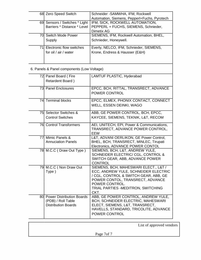
68 Zero Speed Switch Schneider -SAMWHA, IFM, Rockwell
Automation, Siemens, Pepperl+Fuchs, Pyrotech 69 Sensors / Switches * Light IFM, SICK, ROCKWELL AUTOMATION,
Barriers * Distance * Level PEPPERL + FUCHS, SIEMENS, Schnieder,
Dimetix AG 70 Switch Mode Power SIEMENS, IFM, Rockwell Automation, BHEL,
Supply Schnieder, Honeywell.
71 Electronic flow switches Everly, NELCO, IFM, Schnieder, SIEMENS,
for oil / air / water Krone, Endress & Hausser (E&H)
6. Panels & Panel components (Low Voltage)
72 Panel Board ( Fire LAMTUF PLASTIC, Hyderabad
Retardent Board )
73 Panel Enclosures EPCC, BCH, RITTAL, TRANSRECT, ADVANCE
POWER CONTROL
74 Terminal blocks EPCC, ELMEX, PHONIX CONTACT, CONNECT
WELL, ESSEN DEINKI, WAGO
75 Selector Switches & ABB, GE POWER CONTROL, BCH, EPCC,
Control Switches KAYCEE, SIEMENS, TEKNIK, L&T, RECOM
76 Control Transformers AEI, UNITECH, EPI, Power & Communications,
TRANSRECT, ADVANCE POWER CONTROL,
EEW
77 Mimic Panels & L&T, ADVANI OERLIKON, GE Power Control,
Annuciation Panels BHEL, BCH, TRANSRECT, MINLEC, Tirupati
Electronics, ADVANCE POWER CONTOL
78 M.C.C ( Draw Out Type ) SIEMENS, BCH, L&T, ANDREW YULE,
SCHNEIDER ELECTRIC/ CGL, CONTROL &
SWITCH GEAR, ABB, ADVANCE POWER
CONTROL
79 M.C.C ( Non Draw Out SIEMENS, BCH, MAHESWARI ELECT., L&T /
Type ) ECC, ANDREW YULE, SCHNEIDER ELECTRIC
/ CGL, CONTROL & SWITCH GEAR, ABB, GE
POWER CONTOL, TRANSRECT, ADVANCE POWER CONTROL.
TRIAL PARTIES -MEDITRON, SWITCHING
CKT.
80 Power Distribution Boards ABB, GE POWER CONTROL, ANDREW YULE,
(PDB) / Roll Table BCH, SCHNEIDER ELECTRIC, MAHESWARI
Distribution Boards ELECT, SIEMENS, L&T, TRANSRECT,
HAVELLS, STANDARD, TRICOLITE, ADVANCE
POWER CONTROL
List of approved vendors
Page 7of 7
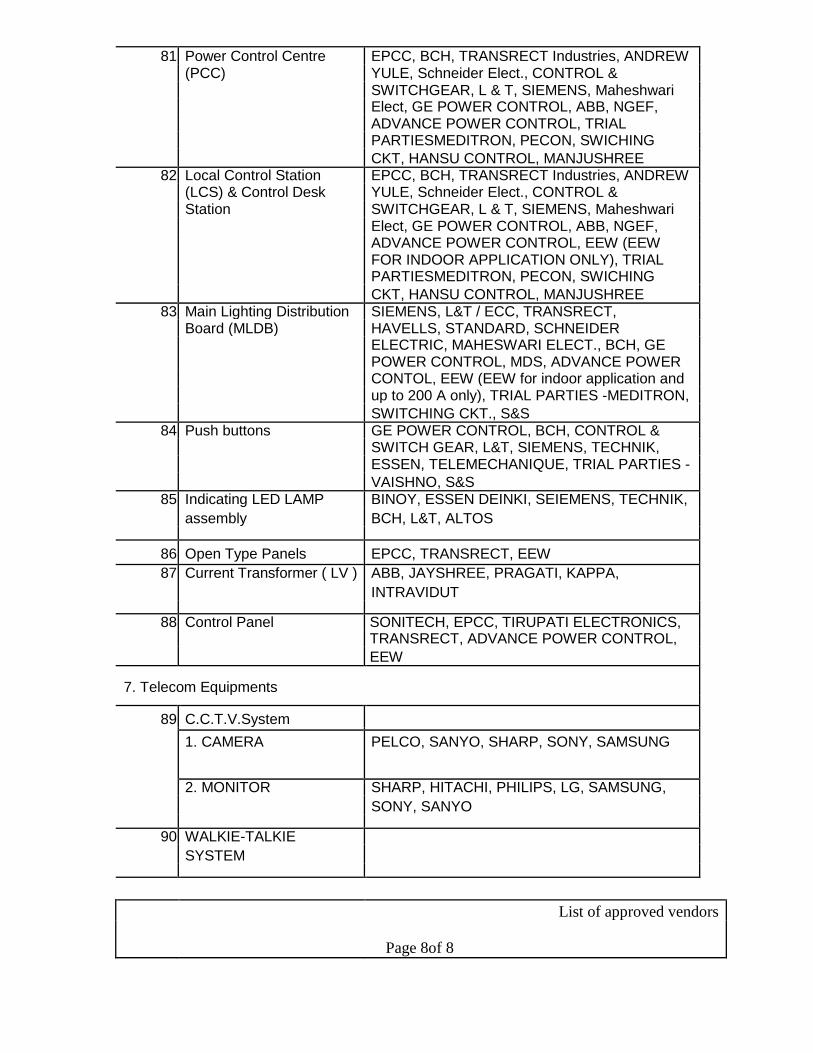
81 Power Control Centre EPCC, BCH, TRANSRECT Industries, ANDREW
(PCC) YULE, Schneider Elect., CONTROL &
SWITCHGEAR, L & T, SIEMENS, Maheshwari Elect, GE POWER CONTROL, ABB, NGEF,
ADVANCE POWER CONTROL, TRIAL
PARTIESMEDITRON, PECON, SWICHING
CKT, HANSU CONTROL, MANJUSHREE 82 Local Control Station EPCC, BCH, TRANSRECT Industries, ANDREW
(LCS) & Control Desk YULE, Schneider Elect., CONTROL &
Station SWITCHGEAR, L & T, SIEMENS, Maheshwari
Elect, GE POWER CONTROL, ABB, NGEF,
ADVANCE POWER CONTROL, EEW (EEW
FOR INDOOR APPLICATION ONLY), TRIAL
PARTIESMEDITRON, PECON, SWICHING
CKT, HANSU CONTROL, MANJUSHREE
83 Main Lighting Distribution SIEMENS, L&T / ECC, TRANSRECT,
Board (MLDB) HAVELLS, STANDARD, SCHNEIDER ELECTRIC, MAHESWARI ELECT., BCH, GE
POWER CONTROL, MDS, ADVANCE POWER
CONTOL, EEW (EEW for indoor application and
up to 200 A only), TRIAL PARTIES -MEDITRON,
SWITCHING CKT., S&S
84 Push buttons GE POWER CONTROL, BCH, CONTROL &
SWITCH GEAR, L&T, SIEMENS, TECHNIK,
ESSEN, TELEMECHANIQUE, TRIAL PARTIES -
VAISHNO, S&S
85 Indicating LED LAMP BINOY, ESSEN DEINKI, SEIEMENS, TECHNIK,
assembly BCH, L&T, ALTOS
86 Open Type Panels EPCC, TRANSRECT, EEW
87 Current Transformer ( LV ) ABB, JAYSHREE, PRAGATI, KAPPA,
INTRAVIDUT
88 Control Panel SONITECH, EPCC, TIRUPATI ELECTRONICS,
TRANSRECT, ADVANCE POWER CONTROL,
EEW
7. Telecom Equipments
89 C.C.T.V.System
1. CAMERA PELCO, SANYO, SHARP, SONY, SAMSUNG
2. MONITOR SHARP, HITACHI, PHILIPS, LG, SAMSUNG,
SONY, SANYO
90 WALKIE-TALKIE
SYSTEM
List of approved vendors
Page 8of 8
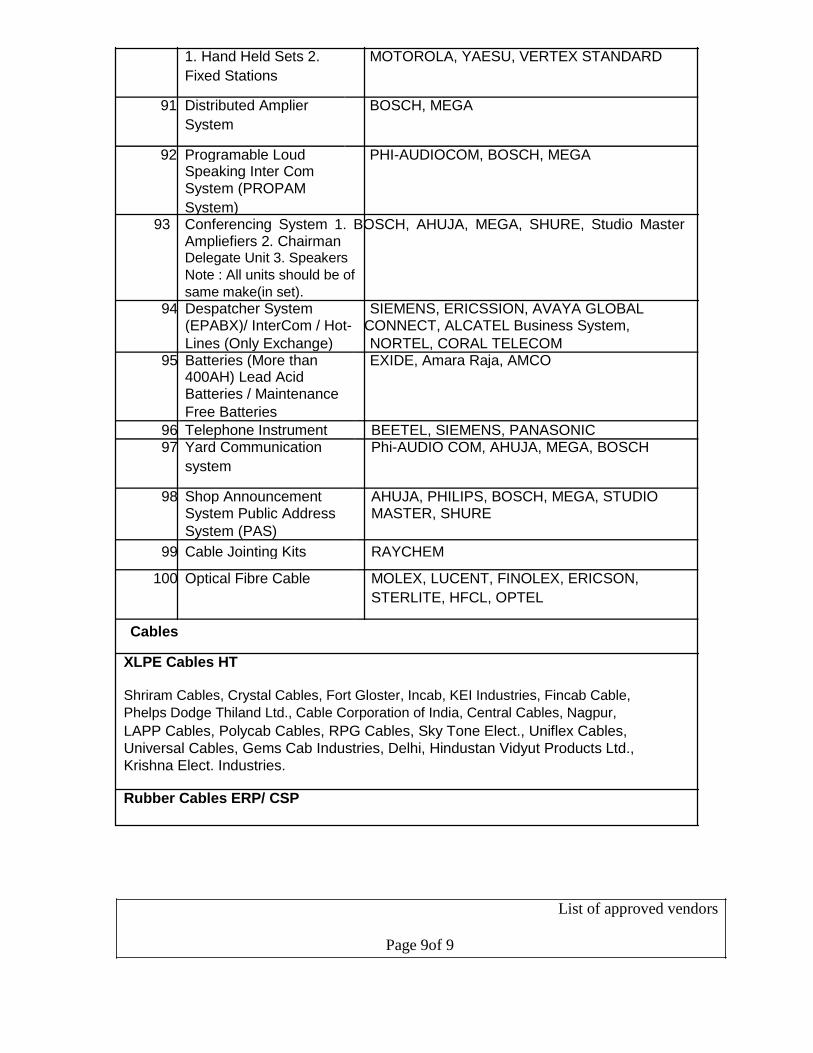
1. Hand Held Sets 2. MOTOROLA, YAESU, VERTEX STANDARD
Fixed Stations
91 Distributed Amplier BOSCH, MEGA
System
92 Programable Loud PHI-AUDIOCOM, BOSCH, MEGA Speaking Inter Com
System (PROPAM
System) 93 Conferencing System 1. BOSCH, AHUJA, MEGA, SHURE, Studio Master
Ampliefiers 2. Chairman Delegate Unit 3. Speakers
Note : All units should be of
same make(in set).
94 Despatcher System SIEMENS, ERICSSION, AVAYA GLOBAL (EPABX)/ InterCom / Hot- CONNECT, ALCATEL Business System,
Lines (Only Exchange) NORTEL, CORAL TELECOM 95 Batteries (More than EXIDE, Amara Raja, AMCO
400AH) Lead Acid
Batteries / Maintenance
Free Batteries
96 Telephone Instrument BEETEL, SIEMENS, PANASONIC 97 Yard Communication Phi-AUDIO COM, AHUJA, MEGA, BOSCH
system
98 Shop Announcement AHUJA, PHILIPS, BOSCH, MEGA, STUDIO System Public Address MASTER, SHURE
System (PAS)
99 Cable Jointing Kits RAYCHEM
100 Optical Fibre Cable MOLEX, LUCENT, FINOLEX, ERICSON,
STERLITE, HFCL, OPTEL
Cables
XLPE Cables HT
Shriram Cables, Crystal Cables, Fort Gloster, Incab, KEI Industries, Fincab Cable,
Phelps Dodge Thiland Ltd., Cable Corporation of India, Central Cables, Nagpur, LAPP Cables, Polycab Cables, RPG Cables, Sky Tone Elect., Uniflex Cables,
Universal Cables, Gems Cab Industries, Delhi, Hindustan Vidyut Products Ltd.,
Krishna Elect. Industries.
Rubber Cables ERP/ CSP
List of approved vendors
Page 9of 9
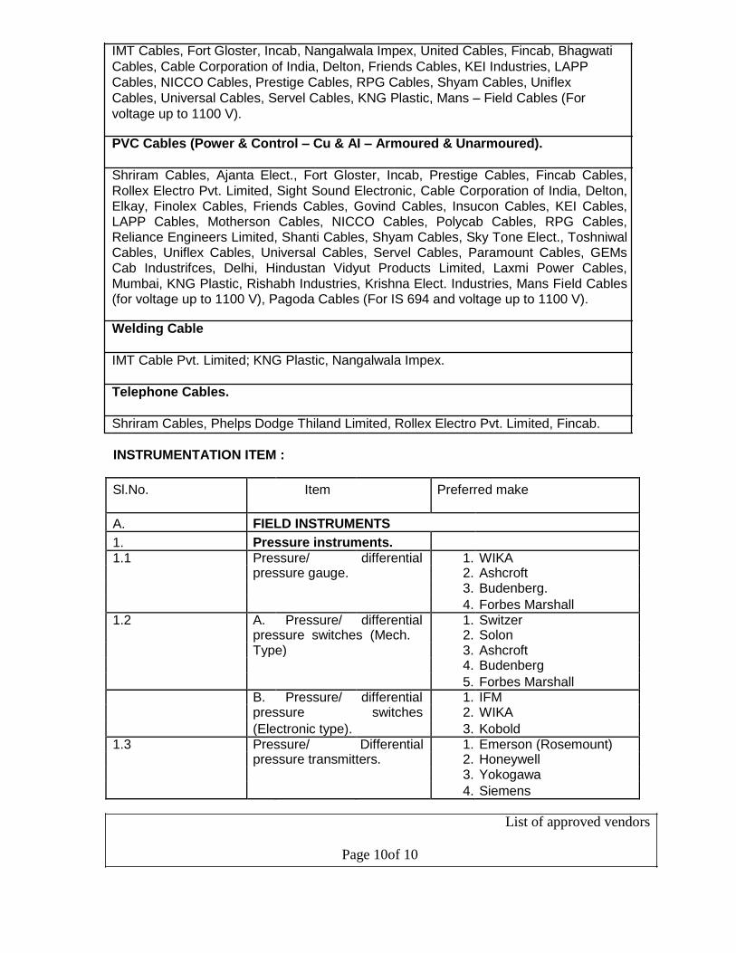
IMT Cables, Fort Gloster, Incab, Nangalwala Impex, United Cables, Fincab, Bhagwati
Cables, Cable Corporation of India, Delton, Friends Cables, KEI Industries, LAPP
Cables, NICCO Cables, Prestige Cables, RPG Cables, Shyam Cables, Uniflex
Cables, Universal Cables, Servel Cables, KNG Plastic, Mans – Field Cables (For
voltage up to 1100 V).
PVC Cables (Power & Control – Cu & AI – Armoured & Unarmoured).
Shriram Cables, Ajanta Elect., Fort Gloster, Incab, Prestige Cables, Fincab Cables,
Rollex Electro Pvt. Limited, Sight Sound Electronic, Cable Corporation of India, Delton, Elkay, Finolex Cables, Friends Cables, Govind Cables, Insucon Cables, KEI Cables, LAPP Cables, Motherson Cables, NICCO Cables, Polycab Cables, RPG Cables, Reliance Engineers Limited, Shanti Cables, Shyam Cables, Sky Tone Elect., Toshniwal Cables, Uniflex Cables, Universal Cables, Servel Cables, Paramount Cables, GEMs Cab Industrifces, Delhi, Hindustan Vidyut Products Limited, Laxmi Power Cables,
Mumbai, KNG Plastic, Rishabh Industries, Krishna Elect. Industries, Mans Field Cables (for voltage up to 1100 V), Pagoda Cables (For IS 694 and voltage up to 1100 V).
Welding Cable
IMT Cable Pvt. Limited; KNG Plastic, Nangalwala Impex.
Telephone Cables.
Shriram Cables, Phelps Dodge Thiland Limited, Rollex Electro Pvt. Limited, Fincab.
INSTRUMENTATION ITEM :
Sl.No. Item Preferred make
A. FIELD INSTRUMENTS
1. Pressure instruments. 1.1 Pressure/ differential 1. WIKA
pressure gauge. 2. Ashcroft 3. Budenberg.
4. Forbes Marshall 1.2 A. Pressure/ differential 1. Switzer
pressure switches (Mech. 2. Solon Type) 3. Ashcroft 4. Budenberg
5. Forbes Marshall B. Pressure/ differential 1. IFM pressure switches 2. WIKA
(Electronic type). 3. Kobold 1.3 Pressure/ Differential 1. Emerson (Rosemount)
pressure transmitters. 2. Honeywell 3. Yokogawa
4. Siemens
List of approved vendors
Page 10of 10

5. E & H
6. ABB
2. Temperature Instrument/
Sensors 2.1 Temperature gauges. 1. WIKA
2. Ashcroft
3. Budenberg
2.2 Thermocouple & RTD/ 1. Tempsens
thermo well. 2. Temptech
3. Toshniwal Industries
4. Detriv
2.3 Temperature Switch 1. IFM
2. WIKA
3. Switzer 2.4 Temperature Transmitter. 1. Emerson (Rosemount)
2. Yokogawa
3. Honeywell
4. MTL
5. Phoenix 2.5 Infrared radiation pyrometer/ 1. Land
portable. 2. Raytek
3. Ircon
4. Impac
5. Keller HCW
3. FLOW INSTRUMENT/ SENSORS
3.1 Rotameters 1. Forbes-Marshall
2. Eureka Instruments
3. Chemtrols
4. Rota Instruments
5. SMC 3.2 Orifice plate & flanges 1. Engineering Specialties
assembly/ venture, flow 2. Micro-precision.
nozzle. 3. Instrumentation Limited.
4. Uni-Control 3.3 DP type flow/ level 1. Emerson (Rosemount)
transmitters. 2. Honeywell
3. Yokogawa
4. Siemens
5. E & H
6. ABB 3.4 Flow Switch 1. IFM
2. Kobold
3. Mobrey 3.5 Electromagnetic flow meter. 1. Yokogawa
2. Emerson (Rosemount)
3. Forbes-Marshall
4. Endress & Hauser
List of approved vendors
Page 11of 11
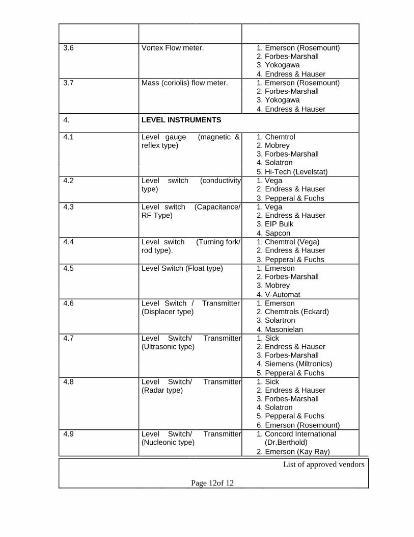
3.6 Vortex Flow meter. 1. Emerson (Rosemount)
2. Forbes-Marshall
3. Yokogawa
4. Endress & Hauser 3.7 Mass (coriolis) flow meter. 1. Emerson (Rosemount)
2. Forbes-Marshall
3. Yokogawa
4. Endress & Hauser
4. LEVEL INSTRUMENTS
4.1 Level gauge (magnetic & 1. Chemtrol
reflex type) 2. Mobrey
3. Forbes-Marshall
4. Solatron
5. Hi-Tech (Levelstat)
4.2 Level switch (conductivity 1. Vega
type) 2. Endress & Hauser
3. Pepperal & Fuchs 4.3 Level switch (Capacitance/ 1. Vega
RF Type) 2. Endress & Hauser
3. EIP Bulk
4. Sapcon
4.4 Level switch (Turning fork/ 1. Chemtrol (Vega)
rod type). 2. Endress & Hauser
3. Pepperal & Fuchs
4.5 Level Switch (Float type) 1. Emerson
2. Forbes-Marshall
3. Mobrey
4. V-Automat
4.6 Level Switch / Transmitter 1. Emerson
(Displacer type) 2. Chemtrols (Eckard)
3. Solartron
4. Masonielan 4.7 Level Switch/ Transmitter 1. Sick
(Ultrasonic type) 2. Endress & Hauser
3. Forbes-Marshall
4. Siemens (Miltronics)
5. Pepperal & Fuchs 4.8 Level Switch/ Transmitter 1. Sick
(Radar type) 2. Endress & Hauser
3. Forbes-Marshall
4. Solatron
5. Pepperal & Fuchs
6. Emerson (Rosemount)
4.9 Level Switch/ Transmitter 1. Concord International
(Nucleonic type) (Dr.Berthold)
2. Emerson (Kay Ray)
List of approved vendors
Page 12of 12
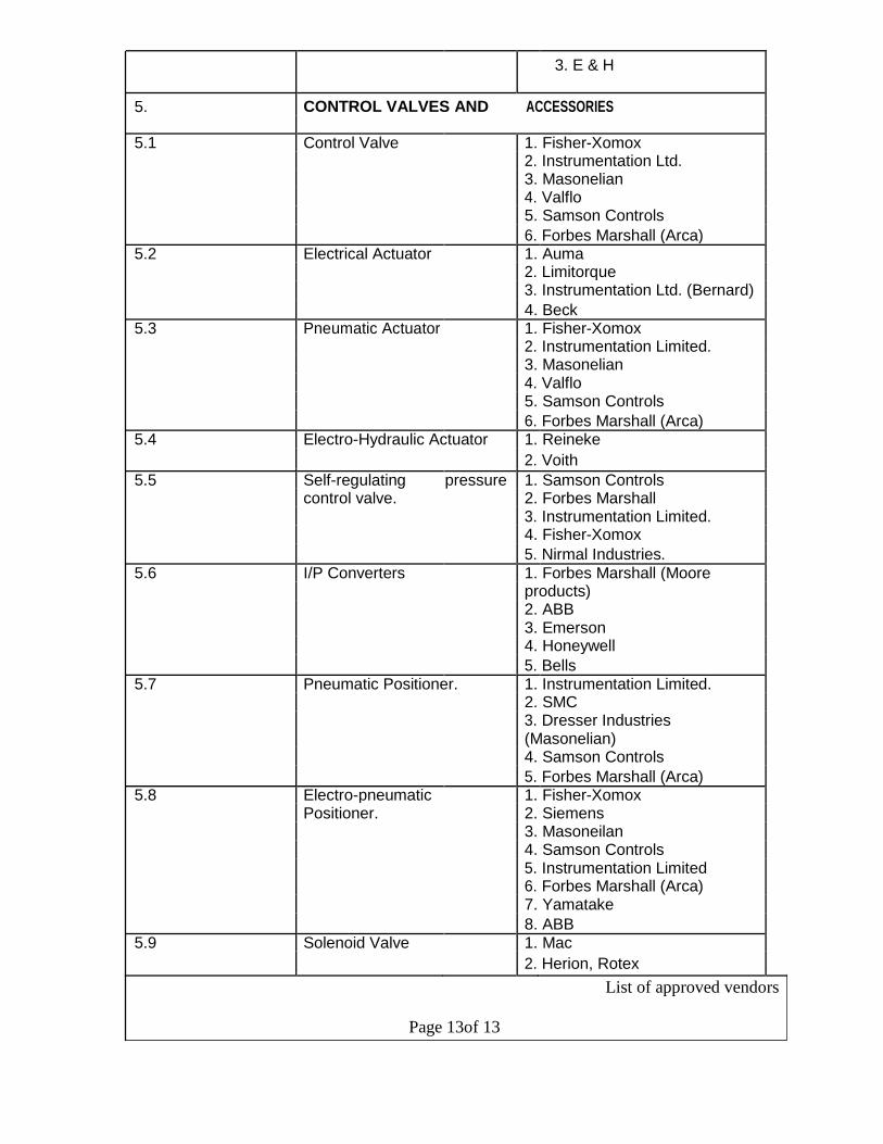
3. E & H
5. CONTROL VALVES AND ACCESSORIES
5.1 Control Valve 1. Fisher-Xomox
2. Instrumentation Ltd.
3. Masonelian
4. Valflo
5. Samson Controls
6. Forbes Marshall (Arca) 5.2 Electrical Actuator 1. Auma
2. Limitorque
3. Instrumentation Ltd. (Bernard)
4. Beck 5.3 Pneumatic Actuator 1. Fisher-Xomox
2. Instrumentation Limited.
3. Masonelian
4. Valflo
5. Samson Controls
6. Forbes Marshall (Arca) 5.4 Electro-Hydraulic Actuator 1. Reineke
2. Voith
5.5 Self-regulating pressure 1. Samson Controls
control valve. 2. Forbes Marshall
3. Instrumentation Limited.
4. Fisher-Xomox
5. Nirmal Industries.
5.6 I/P Converters 1. Forbes Marshall (Moore
products)
2. ABB
3. Emerson
4. Honeywell
5. Bells 5.7 Pneumatic Positioner. 1. Instrumentation Limited.
2. SMC
3. Dresser Industries
(Masonelian)
4. Samson Controls
5. Forbes Marshall (Arca) 5.8 Electro-pneumatic 1. Fisher-Xomox
Positioner. 2. Siemens
3. Masoneilan
4. Samson Controls
5. Instrumentation Limited
6. Forbes Marshall (Arca)
7. Yamatake
8. ABB 5.9 Solenoid Valve 1. Mac
2. Herion, Rotex
List of approved vendors
Page 13of 13
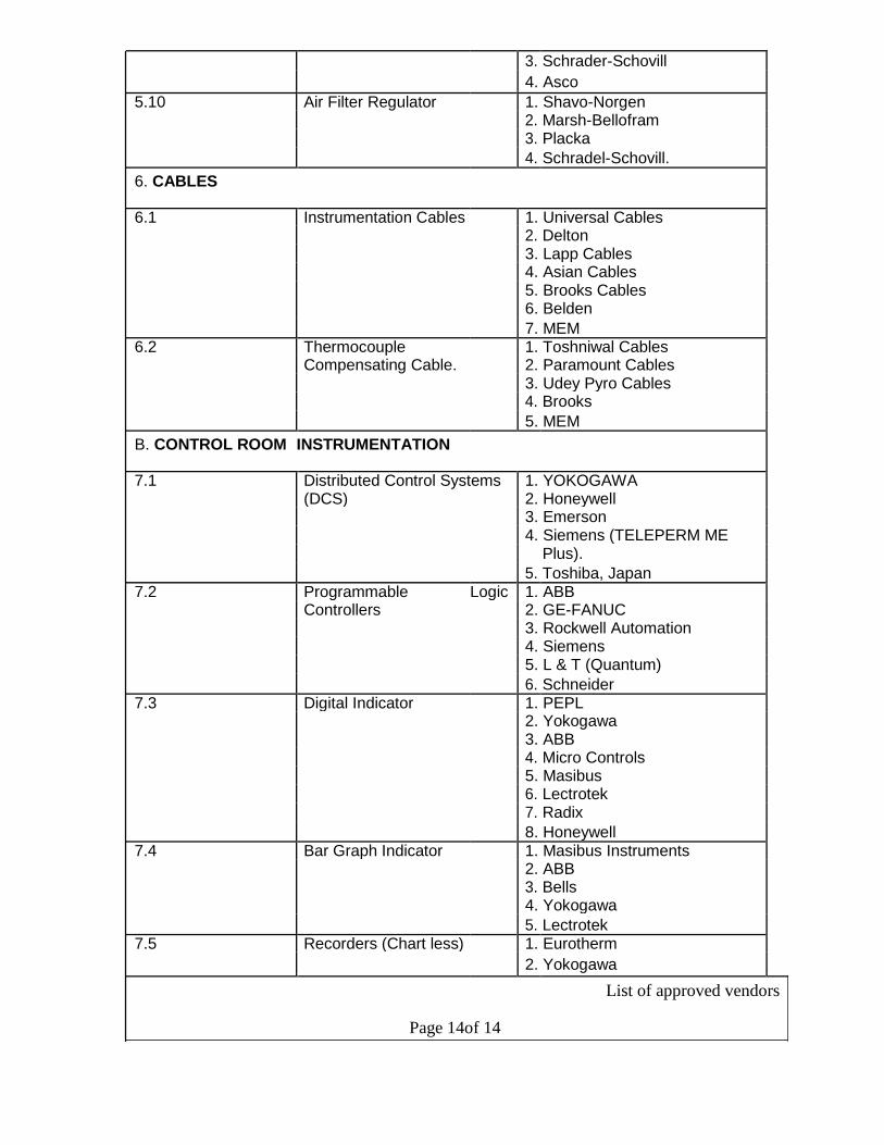
3. Schrader-Schovill
4. Asco
5.10 Air Filter Regulator 1. Shavo-Norgen
2. Marsh-Bellofram
3. Placka
4. Schradel-Schovill.
6. CABLES
6.1 Instrumentation Cables 1. Universal Cables
2. Delton
3. Lapp Cables
4. Asian Cables
5. Brooks Cables
6. Belden
7. MEM 6.2 Thermocouple 1. Toshniwal Cables
Compensating Cable. 2. Paramount Cables
3. Udey Pyro Cables
4. Brooks
5. MEM
B. CONTROL ROOM INSTRUMENTATION
7.1 Distributed Control Systems 1. YOKOGAWA
(DCS) 2. Honeywell
3. Emerson
4. Siemens (TELEPERM ME
Plus).
5. Toshiba, Japan
7.2 Programmable Logic 1. ABB
Controllers 2. GE-FANUC
3. Rockwell Automation
4. Siemens
5. L & T (Quantum)
6. Schneider
7.3 Digital Indicator 1. PEPL
2. Yokogawa
3. ABB
4. Micro Controls
5. Masibus
6. Lectrotek
7. Radix
8. Honeywell
7.4 Bar Graph Indicator 1. Masibus Instruments
2. ABB
3. Bells
4. Yokogawa
5. Lectrotek 7.5 Recorders (Chart less) 1. Eurotherm
2. Yokogawa
List of approved vendors
Page 14of 14

3. Honeywell
4. ABB
7.6 Microprocessor Based 1. Yokogawa
Controller 2. Siemens
3. Honeywell
4. Eurotherm
5. MTL
6. Forbes Marshall
7. Toshiba 7.7 Digital Scanners 1. Radix
2. Micro Controls
3. Masibus Instruments
4. Lectrotek
5. PEPL 7.8 DC Power Supply Unit 1. Aplab
2. Phoenix
3. Schneider
4. P&F
7.9 IS Interface/ Zenner Barrier 1. Pepperl & Fuchs
2. MTL
3. Stahl 7.10 Signal Isolators 1. Pepperl & Fuchs
2. MTL
3. Yokogawa
4. Forbes Marshall (Protech)
5. Phoenix
7.11 Annunciation System 1. IIC
2. Minilec
3. Digicont
4. MTL
5. BETA Instruments
6. Procon
7.12 Instrument Panels/ Control 1. Rittal
Desk 2. Pyrotech
3. Instrumentation Ltd.
7.13 Manual Loaders 1. Masibus
2. PEPL
3. Lectrotek 7.14 Totalizer 1. Masibus
2. PEPL
3. Lectrotek
4. Bivak
C. ANALYTICAL/ SPECIAL INSTRUMENTS
8.1 Gas Analysis Instruments 1. ABB (H&B)
2. Emerson
3. Siemens
4. Servomax
5. Yokogawa
List of approved vendors
Page 15of 15
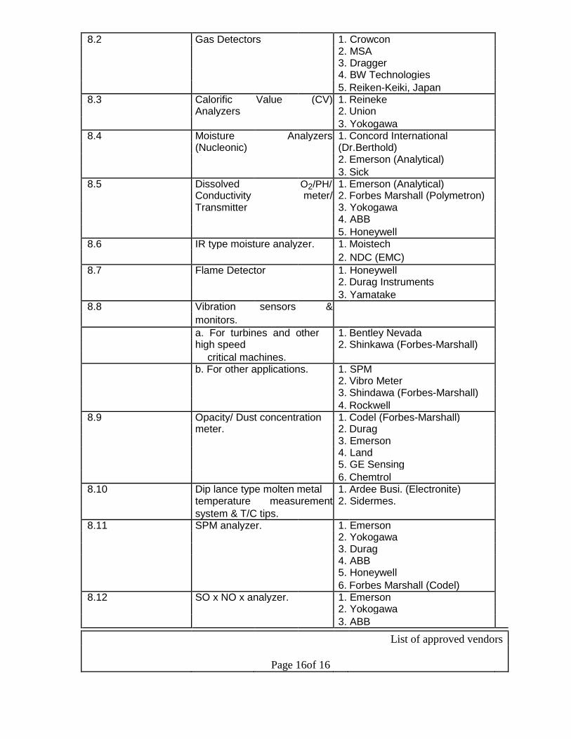
8.2 Gas Detectors 1. Crowcon
2. MSA
3. Dragger
4. BW Technologies
5. Reiken-Keiki, Japan
8.3 Calorific Value (CV) 1. Reineke
Analyzers 2. Union
3. Yokogawa 8.4 Moisture Analyzers 1. Concord International
(Nucleonic) (Dr.Berthold)
2. Emerson (Analytical)
3. Sick
8.5 Dissolved O2/PH/ 1. Emerson (Analytical)
Conductivity meter/ 2. Forbes Marshall (Polymetron)
Transmitter 3. Yokogawa
4. ABB
5. Honeywell
8.6 IR type moisture analyzer. 1. Moistech
2. NDC (EMC)
8.7 Flame Detector 1. Honeywell
2. Durag Instruments
3. Yamatake 8.8 Vibration sensors &
monitors.
a. For turbines and other 1. Bentley Nevada
high speed 2. Shinkawa (Forbes-Marshall)
critical machines. b. For other applications. 1. SPM
2. Vibro Meter
3. Shindawa (Forbes-Marshall)
4. Rockwell
8.9 Opacity/ Dust concentration 1. Codel (Forbes-Marshall)
meter. 2. Durag
3. Emerson
4. Land
5. GE Sensing
6. Chemtrol
8.10 Dip lance type molten metal 1. Ardee Busi. (Electronite)
temperature measurement 2. Sidermes.
system & T/C tips. 8.11 SPM analyzer. 1. Emerson
2. Yokogawa
3. Durag
4. ABB
5. Honeywell
6. Forbes Marshall (Codel) 8.12 SO x NO x analyzer. 1. Emerson
2. Yokogawa
3. ABB
List of approved vendors
Page 16of 16

4. Siemens
5. Honeywell
6. Forbes Marshall (Codel)
9. INFORMATION & AUTOMATION SYSTEMS
9.1 Computer (Servers) 1. IBM
2. HP
3. SUN
9.2 Computer (Work Stations/ Laptop) 1. IBM
2. COMPAQ
3. LENOVO
4. DELL
5. HP
9.3 Dot Matrix Printer 1. EPSON
2. TVSE
9.4 Laser / Inkjet Printer/ Scanners. 1. HP
9.5 PLC 1. ABB
2. GE-FANUC
3. ROCKWELL AUTOMATION
4. SIEMENS
5. L&T (Quantum)
6. SCHNEIDER
10. NETWORK EQUIPMENT
10.1 Active Switching & Routing 1. CISCO
10.2 Active other components. 1. Alllied Telesys
2. RAD
3. Xycel
10.3 Passive Cabling components. 1. Lucent
2. AMP
3. Systimax
4. Molex
5. R & M 10.4 Passive Racks 1. APW President
2. Rittal
3. Krone 10.5 Industrial Grade Ethernet Switches. 1. Hirschmann
2. Sixnet
10.6 LCD Projector. 1. Hitachi
2. Canon
3. Panasonic
4. Soni
5. Sharp
6. HP 10.7 Computer Furniture 1. Godrej
2. Methodex
List of approved vendors
Page 17of 17

3. Wipro
10.8 UPS 1. APC 2. Tata Libert (Emerson) 3. Fuji
4. GE
11. WEIGH BRIDGE SYSTEMS
11.1 Static Rail Weigh 1. M/s Pivotex OY, Finland Bridge 2. M/s Weighload Techlologies, UK 3. M/s Procon Engineering Limited, UK 4. M/s Carlschenck AG, Germany 5. M/s Molen, Sweden 6. M/s Elon Engineering Industrial Weighing System Limited, UK.
7. M/s ACME Automation Pvt. Limited. 11.2 In-motion Rail 1. M/s Carl Schenck AG, Germany
Weighing Systems. 2. M/s AMTAB, Sweden 3. M/s Pivotex OY, Finland 4. M/s Weighload Technologies, UK 5. M/s Procon Engineering Limited, UK 6. M/s Eldigi Measurematics Pvt.Ltd., USA
7. M/s ACME Automation Pvt. Limited. 11.3 Road Weigh Bridge 1. M/s Carl Schenck AG, Germany
2. M/s AMTAB, Sweden 3. M/s Pivotex OY, Finland 4. M/s Weighload Technologies, UK 5. M/s Procon Engineering Limited, UK 6. M/s Eldigi Measurematics Pvt.Ltd., USA 7. M/s Sartorius Mechatronics, Bangalore 8. M/s Melter Teledo, UK.
9. M/s ACME Automation Pvt. Limited. 11.4 Hopper Weighing 1. M/s Carl Schenck AG, Germany
System. 2. M/s Molen, Sweden 3. M/s Siemens AG, Germany 4. M/s Procon Engineering Limited, UK 5. M/s Eldigi Measurematics Pvt.Ltd., USA 6. M/s Kistler-Morse Automation Ltd., USA 7. M/s Nova
8. M/s ACME Automation Pvt. Limited. 11.5 Belt Weigher & Weigh 1. M/s Carl Schenck AG, Germany
Feeder 2. M/s S-E-G Instruments AB, Sweden 3. M/s Dosatec SA, Switzerland 4. M/s Procon Engineering Ltd., UK 5. M/s Kistler-Morse Automation Limited.
6. M/s ACME Automation Pvt. Limited. 11.6 Crane Weighing 1. M/s Technical Weighing Services, USA
System. 2. M/s Eldigi Measurematics Pvt.Ltd., USA
3. M/s Eilon Engineering Ind. Weighing Systems
List of approved vendors
Page 18of 18

Limited, UK.
4. M/s Carl Schenck AG, Germany
5. M/s Tamtron OY, Finland
6. M/s Procon Engineering Limited, UK
7. M/s EHP Waegetecchink GmbH, Germany
8. M/s Weighload Technologies, UK 11.7 Load Cell 1. M/s HBM, Germany
2. M/s Siemens AG, Germany
3. M/s Flintab, Germany
4. M/s Sartorius Mechetronics, Germany
5. M/s Tedia, Germany
6. M/s BLH, UK
7. M/s Molen, Sweden 11.8 Weight Transmitter 1. M/s Sartorius Mechetronics, Bangalore
2. M/s Flintak, UK
3. M/s Carl Schenck AG, Germany
4. M/s Molen, Sweden
12.0 SENSORS:
12.1 TEMPERATURE
SENSORS 12.1.1 Pt-Rh element M/s Arora Matthey Ltd., Kolkata
M/s Hindustan Platinum
M/s Parekh Platinum ltd., Mumbai 12.1.2 Contact Thermometers M/S A.N. Instruments
M/S Detriv Instrumentation & Electronics Pvt. Ltd.,
Mumbai
M/S Waaree Instruments, Mumbai
M/S Toshniwal Industries Pvt. Ltd. , Ajmer
M/S Wika Instruments India Pvt. Ltd., Pune
12.1.3 Portable / Hand held M/s Tempsens Instruments (i) Pvt. Ltd., Udaipur
pyrometers M/S Toshniwal Industries Pvt. Ltd. , Ajmer
M/S Eurotherms Del India Pvt. Ltd., Kolkata
M/S Waaree Instruments, Mumbai
M/S Nagman Instruments & Electronics Pvt. Ltd.,
Chennai
• ACWE EQUIPMENTS
1. AIR WASHHING M/s Batliboi, M/s ACCO, M/s ABB FLAKT,
UNITS M/s F Harley Calcutta, M/s Mesina
Bombay,
M/s S K Systems Kolkata,
M/s Air Technico, Kolkata.
M/s Marco Blowers, Kolkata 2. WINDOW AIR CONDITIONERS M/s ACCO, M/s VOLTAS, M/s Blue Star,
M/s SIEL AIRCON (USHA), M/s Carier
Aircon.
M/s Videocon
List of approved vendors
Page 19of 19
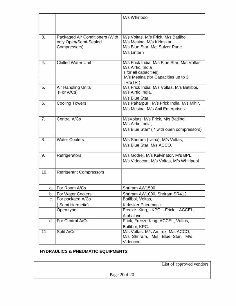
M/s Whirlpool
3. Packaged Air Conditioners (With M/s Voltas, M/s Frick, M/s Batliboi,
only Open/Semi-Sealed M/s Mesina, M/s Kirloskar, Compressors) M/s Blue Star, M/s Sulzer Pune.
M/s Lintern
4. Chilled Water Unit M/s Frick India, M/s Blue Star, M/s Voltas. M/s Airtic, India ( for all capacities) M/s Mesina (for Capacities up to 3
TR/5TR ) 5. Air Handling Units M/s Frick India, M/s Voltas, M/s Batliboi,
(For A/Cs) M/s Airtic India.
M/s Blue Star
6. Cooling Towers M/s Paharpur , M/s Frick India, M/s Mihir,
M/s Mesina, M/s Anil Enterprises.
7. Central A/Cs M/sVoltas, M/s Frick, M/s Batliboi, M/s Airtic India,
M/s Blue Star* ( * with open compressors)
8. Water Coolers M/s Shriram (Usha), M/s Voltas,
M/s Blue Star, M/s ACCO.
9. Refrigerators M/s Godrej, M/s Kelvinator, M/s BPL,
M/s Videocon, M/s Voltas, M/s Whirlpool
10. Refrigerant Compressors
a. For Room A/Cs Shriram AW1500
b. For Water Coolers Shriram AW1000, Shriram SR412. c. For packaed A/Cs Batliboi, Voltas,
( Semi Hermetic) Kirlosker Pneumatic. Open type Freeze King, KPC, Frick, ACCEL,
Alphalavel.
d. For Central A/Cs Frick, Freeze King, ACCEL, Voltas,
Batliboi, KPC. 11. Split A/Cs M/s Voltas, M/s Amtrex, M/s ACCO,
M/s Shriram, M/s Blue Star, M/s
Videocon.
HYDRAULICS & PNEUMATIC EQUIPMENTS
List of approved vendors
Page 20of 20
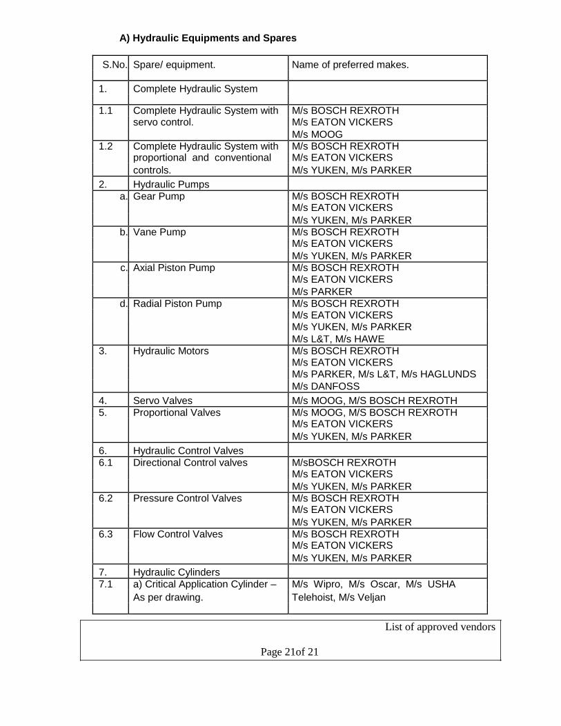
A) Hydraulic Equipments and Spares
S.No. Spare/ equipment. Name of preferred makes.
1. Complete Hydraulic System
1.1 Complete Hydraulic System with M/s BOSCH REXROTH servo control. M/s EATON VICKERS
M/s MOOG 1.2 Complete Hydraulic System with M/s BOSCH REXROTH
proportional and conventional M/s EATON VICKERS
controls. M/s YUKEN, M/s PARKER
2. Hydraulic Pumps a. Gear Pump M/s BOSCH REXROTH
M/s EATON VICKERS
M/s YUKEN, M/s PARKER b. Vane Pump M/s BOSCH REXROTH
M/s EATON VICKERS
M/s YUKEN, M/s PARKER c. Axial Piston Pump M/s BOSCH REXROTH
M/s EATON VICKERS
M/s PARKER
d. Radial Piston Pump M/s BOSCH REXROTH M/s EATON VICKERS M/s YUKEN, M/s PARKER
M/s L&T, M/s HAWE
3. Hydraulic Motors M/s BOSCH REXROTH M/s EATON VICKERS M/s PARKER, M/s L&T, M/s HAGLUNDS
M/s DANFOSS
4. Servo Valves M/s MOOG, M/S BOSCH REXROTH
5. Proportional Valves M/s MOOG, M/S BOSCH REXROTH M/s EATON VICKERS
M/s YUKEN, M/s PARKER
6. Hydraulic Control Valves 6.1 Directional Control valves M/sBOSCH REXROTH
M/s EATON VICKERS
M/s YUKEN, M/s PARKER 6.2 Pressure Control Valves M/s BOSCH REXROTH
M/s EATON VICKERS
M/s YUKEN, M/s PARKER
6.3 Flow Control Valves M/s BOSCH REXROTH M/s EATON VICKERS
M/s YUKEN, M/s PARKER
7. Hydraulic Cylinders 7.1 a) Critical Application Cylinder – M/s Wipro, M/s Oscar, M/s USHA
As per drawing. Telehoist, M/s Veljan
List of approved vendors
Page 21of 21
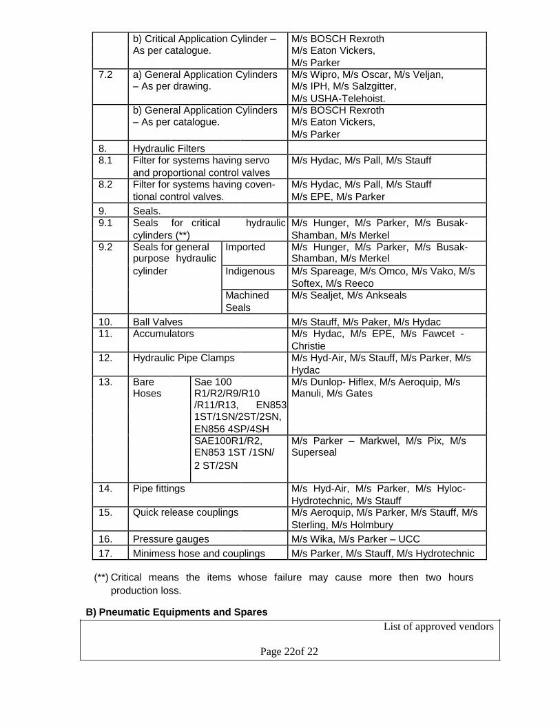
b) Critical Application Cylinder – M/s BOSCH Rexroth As per catalogue. M/s Eaton Vickers,
M/s Parker 7.2 a) General Application Cylinders M/s Wipro, M/s Oscar, M/s Veljan,
– As per drawing. M/s IPH, M/s Salzgitter,
M/s USHA-Telehoist. b) General Application Cylinders M/s BOSCH Rexroth – As per catalogue. M/s Eaton Vickers,
M/s Parker
8. Hydraulic Filters 8.1 Filter for systems having servo M/s Hydac, M/s Pall, M/s Stauff
and proportional control valves 8.2 Filter for systems having coven- M/s Hydac, M/s Pall, M/s Stauff
tional control valves. M/s EPE, M/s Parker
9. Seals. 9.1 Seals for critical hydraulic M/s Hunger, M/s Parker, M/s Busak-
cylinders (**) Shamban, M/s Merkel 9.2 Seals for general Imported M/s Hunger, M/s Parker, M/s Busak-
purpose hydraulic Shamban, M/s Merkel
cylinder
Indigenous M/s Spareage, M/s Omco, M/s Vako, M/s
Softex, M/s Reeco Machined M/s Sealjet, M/s Ankseals
Seals
10. Ball Valves M/s Stauff, M/s Paker, M/s Hydac 11. Accumulators M/s Hydac, M/s EPE, M/s Fawcet -
Christie 12. Hydraulic Pipe Clamps M/s Hyd-Air, M/s Stauff, M/s Parker, M/s
Hydac 13. Bare Sae 100 M/s Dunlop- Hiflex, M/s Aeroquip, M/s
Hoses R1/R2/R9/R10 Manuli, M/s Gates /R11/R13, EN853 1ST/1SN/2ST/2SN,
EN856 4SP/4SH SAE100R1/R2, M/s Parker – Markwel, M/s Pix, M/s EN853 1ST /1SN/ Superseal
2 ST/2SN
14. Pipe fittings M/s Hyd-Air, M/s Parker, M/s Hyloc-
Hydrotechnic, M/s Stauff 15. Quick release couplings M/s Aeroquip, M/s Parker, M/s Stauff, M/s
Sterling, M/s Holmbury
16. Pressure gauges M/s Wika, M/s Parker – UCC
17. Minimess hose and couplings M/s Parker, M/s Stauff, M/s Hydrotechnic
(**) Critical means the items whose failure may cause more then two hours
production loss. B) Pneumatic Equipments and Spares
List of approved vendors
Page 22of 22

1. Air booster pumps/ intensifiers M/s Maximator, M/s Haskel 2. a) Control valves M/s Parker, M/s Ross, M/s Nucon, M/s b) Directional control valves Spirax, M/s Martonair, M/s Schrader c) Pressure control valves Bellow, M/s Crouzet
d) Flow control valves
e) Logic control valves M/s Telemecanique, M/s Festo 3. a) Air preparation unit M/s Airmatic, M/s Parker, M/s Veljan – b) Filters Hydrair, M/s Schrader Bellow, M/s Nucon, c) Regulators M/s Festo, M/s Hydroline d) Lubricators
e) Combination units
f) Diffusers
g) Silencers
h) Mufflers
i) Breathers
4. Air driers M/s Emskay 5. Pipe and fittings M/s Mecman. M/s Legris, M/s Parker Various types of pipes fittings,
PVC, PU and nylon turbine.
PUMPS & C00LING TOWERS
A. COOLING TOWERS M/s Shri Ram Tower Tech. Ltd., M/s Enviro Clean System Ltd., M/s GEA Cooling Towers Chennai, M/s Engg. Services & Accessories Mumbai, M/s Paharpur Cooling Tower Calcutta, M/s Bridge & Roof Ltd. Calcutta, M/s BSBK Bhilai,
M/s DBR Cooling Tower Calcutta.
B. PUMPS a) Horizontal Split Casing M/s Kirloskar,
Centriffugal Pumps M/s Jyoti, 3
M/s Mather & Platt, Q = 500 M /Hr. and
M/s KSB, above
M/s Beacon Weir, H = upto 80 M WC,
M/s Voltas. Direct coupled.
RPM =
1000/1440/2830
Construction - CI, Clear
water service.
b) Multi-Stage Centrifugal M/s Bharat Pumps, M/s KSB, M/s Bareja, Pumps for Cold/Hot M/s Kirloskar, M/s Mather & Platt,
water service. M/s Sulzer/ Khimline.
List of approved vendors
Page 23of 23

c) Vertical Radial/ Mixed M/s Kirloskar, M/s Mcnally, Bangalore,
flow/ Axial M/s Kishore, M/s Jyoti, M/s KSB.
flow/ Turbine Pumps for clear water service
upto 300 M 3/ Hr.
d) Vertical Radial/ Mixed M/s Kirloskar,
flow axial M/s Jyoti,
flow/ Turbine Pumps M/s KSB,
for Clear water service M/s Voltas. service
more than 300 M 3/ hr.
e) Sludge Pumps for M/s HIL, M/s Warman Indore,
pumping sludge M/s Akay Industries,
from effluent treatment M/s Beacon.
plant.
f) Slurry Pumps Vertical M/s Kirloskar, M/s Mcnally, M/s KSB,
& Horizontal M/s Kishore, M/s Beacon Weir. g) Drainage Pumps for M/s Kishore, M/s KSB,
pits, Tunnels M/s Kirloskar, M/s Darling,
Q= 100M3 /Hr., H= up M/s Sam Pumps, M/s Sehra.
to 30 M
h) Dosing Pumps/ M/s Shape tool, M/s Ion Exchange,
Metering Pumps M/s Toshniwal, M/s H-Welore.
i) Submersible mono- M/s Kirloskar, M/s Kishore, M/s Darling,
bioc Pumps for special M/s Calama, M/s Sehra.
drainage and Lifting
Applications.
• VALVES
A. For all steam services, M/s BHEL,
feed water to boiler, hot M/S L & T,
condensate & other M/s KSB,
critical applications for M/s Fouress Engineering Co.,
Pressure 20 Kg/ CM2 M/s NECO Valves (No subsidiary),
(Class 300) and above. M/s Leader Valves Ltd. (Up to Class 300
only)
M/s Mehta Nanavati (Up to Class 300 only).
M/s Fluide Line Valves Company Pvt., Ltd.,
Ahamedabad.
M/s Chemtaech Industrial Valves.
Note : These parties are eligible for
categories (B) & (C) also.
List of approved vendors
Page 24of 24
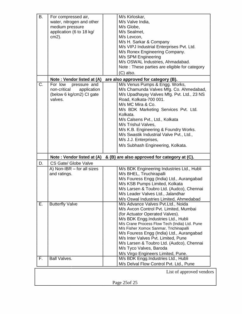
B. For compressed air, M/s Kirloskar,
water, nitrogen and other M/s Valve India,
medium pressure M/s Globe,
application (6 to 18 kg/ M/s Sealmet,
cm2). M/s Levcon,
M/s H. Sarkar & Company
M/s VIPJ Industrial Enterprises Pvt. Ltd.
M/s Ronex Engineering Company.
M/s SPM Engineering
M/s OSWAL Industries, Ahmadabad.
Note : These parties are eligible for category
(C) also.
Note : Vendor listed at (A) are also approved for category (B). C. For low pressure and M/s Venus Pumps & Engg. Works,
non-critical application M/s Chamunda Valves Mfg. Co. Ahmedabad,
(below 6 kg/cm2) CI gate M/s Upadhayay Valves Mfg. Pvt. Ltd., 23 NS
valves. Road, Kolkata-700 001.
M/s MC Mira & Co.
M/s BDK Marketing Services Pvt. Ltd.
Kolkata.
M/s Calsens Pvt., Ltd., Kolkata
M/s Trishul Valves,
M/s K.B. Engineering & Foundry Works.
M/s Swastik Industrial Valve Pvt., Ltd.,
M/s J.J. Enterprises,
M/s Subhash Engineering, Kolkata.
Note : Vendor listed at (A) & (B) are also approved for category at (C).
D. CS Gate/ Globe Valve
A) Non-IBR – for all sizes M/s BDK Engineering Industries Ltd., Hubli
and ratings. M/s BHEL, Tiruchirapalli
M/s Fouress Engg (India) Ltd., Aurangabad
M/s KSB Pumps Limited, Kolkata
M/s Larsen & Toubro Ltd. (Audco), Chennai
M/s Leader Valves Ltd., Jalandhar
M/s Oswal Industries Limited, Ahmedabad E. Butterfly Valve M/s Advance Valves Pvt.Ltd., Noida
M/s Avcon Control Pvt. Limited, Mumbai
(for Actuator Operated Valves).
M/s BDK Engg.Industries Ltd., Hubli M/s Crane Process Flow Tech (India) Ltd. Pune
M/s Fisher Xomox Sanmar, Trichinapalli
M/s Fouress Engg (India) Ltd., Aurangabad
M/s Inter Valves Pvt. Limited, Pune
M/s Larsen & Toubro Ltd. (Audco), Chennai
M/s Tyco Valves, Baroda
M/s Virgo Engineers Limited, Pune. F. Ball Valves. M/s BDK Engg.Industries Ltd., Hubli
M/s Delval Flow Control Pvt. Ltd., Pune
List of approved vendors
Page 25of 25
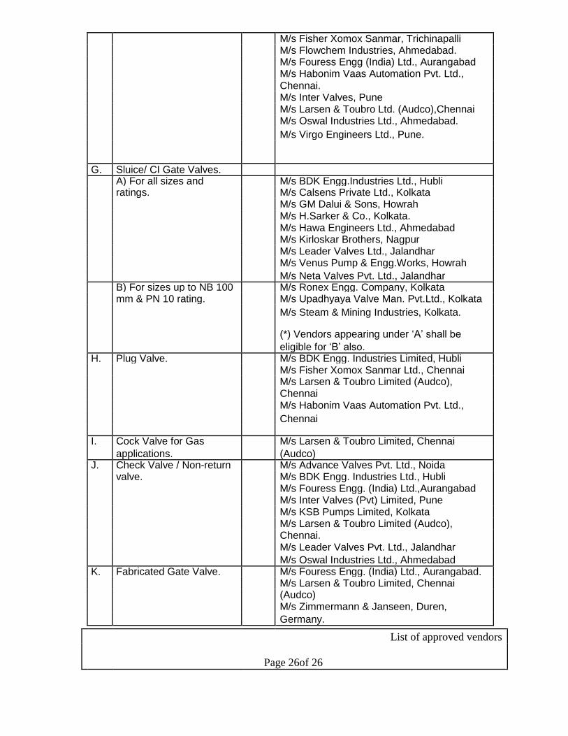
M/s Fisher Xomox Sanmar, Trichinapalli
M/s Flowchem Industries, Ahmedabad.
M/s Fouress Engg (India) Ltd., Aurangabad
M/s Habonim Vaas Automation Pvt. Ltd.,
Chennai.
M/s Inter Valves, Pune
M/s Larsen & Toubro Ltd. (Audco),Chennai
M/s Oswal Industries Ltd., Ahmedabad.
M/s Virgo Engineers Ltd., Pune.
G. Sluice/ CI Gate Valves.
A) For all sizes and M/s BDK Engg.Industries Ltd., Hubli
ratings. M/s Calsens Private Ltd., Kolkata
M/s GM Dalui & Sons, Howrah
M/s H.Sarker & Co., Kolkata.
M/s Hawa Engineers Ltd., Ahmedabad
M/s Kirloskar Brothers, Nagpur
M/s Leader Valves Ltd., Jalandhar
M/s Venus Pump & Engg.Works, Howrah
M/s Neta Valves Pvt. Ltd., Jalandhar B) For sizes up to NB 100 M/s Ronex Engg. Company, Kolkata
mm & PN 10 rating. M/s Upadhyaya Valve Man. Pvt.Ltd., Kolkata
M/s Steam & Mining Industries, Kolkata.
(*) Vendors appearing under ‘A’ shall be
eligible for ‘B’ also. H. Plug Valve. M/s BDK Engg. Industries Limited, Hubli
M/s Fisher Xomox Sanmar Ltd., Chennai
M/s Larsen & Toubro Limited (Audco),
Chennai
M/s Habonim Vaas Automation Pvt. Ltd.,
Chennai
I. Cock Valve for Gas M/s Larsen & Toubro Limited, Chennai
applications. (Audco) J. Check Valve / Non-return M/s Advance Valves Pvt. Ltd., Noida
valve. M/s BDK Engg. Industries Ltd., Hubli
M/s Fouress Engg. (India) Ltd.,Aurangabad
M/s Inter Valves (Pvt) Limited, Pune
M/s KSB Pumps Limited, Kolkata
M/s Larsen & Toubro Limited (Audco),
Chennai.
M/s Leader Valves Pvt. Ltd., Jalandhar
M/s Oswal Industries Ltd., Ahmedabad K. Fabricated Gate Valve. M/s Fouress Engg. (India) Ltd., Aurangabad.
M/s Larsen & Toubro Limited, Chennai (Audco)
M/s Zimmermann & Janseen, Duren,
Germany.
List of approved vendors
Page 26of 26

L. Piston Valve. M/s Uni-Klinger Limited, Pune.
M/s Spirax Marshall Limited, Nagpur. M. Valves for Steam
Application. A. For all sizes and M/s BDK Engg. Industries Limited, Hubli. ratings. M/s Oswal Industries Ltd., Ahmedabad. M/s Larsen & Toubro Limited, Chennai (Audco) M/s Fouress Engg. (India) Ltd., Aurangabad. M/s KSB Pumps Limited, Kolkata. M/s BHEL, Trichurapalli.
M/s Leader Valves Pvt. Limited, Jalandhar B. For sizes up to 50 mm M/s Neta Valves Pvt.Ltd., Jalandhar and Class No. 150 M/s Hawa Valves (India) Pvt.Ltd., Mumbai
ratings. M/s MH Valves Pvt. Ltd., Ahmedabad.
(*) Vendors appearing under ‘A’ shall be
eligible for ‘B’ also). N. Knife Edge Gate Valve. M/s Orbinox India Pvt. Limited, Coimbatore.
M/s Fouress Engg. (India) Ltd., Aurangabad. M/s Vass Ind. Pvt. Limited, Chennai.
M/s Energo Engg., Delhi. O. Non-Ferrous Valve. M/s Leader Valves Limited, Jalandhar.
M/s Zoloto Industries, Jalandhar. M/s Neta Valves Pvt. Ltd., Jalandhar.
M/s Sant Valves Pvt. Ltd., Jalandhar.
• MECHANICAL EQUIPMENT :
1. Gear Box M/s Elecon, M/s NAW, M/s FMG
M/s Shanthi, M/s Greaves.
2. Geared Coupling M/s NAW, M/s HICLIFF, M/s Concord, M/s FMG, M/s Roma Mechanical Works,
M/s Elecon, M/s David Brown, M/s Greaves.
3. Fluid Coupling M/s Voith India, M/s Pembrill, M/s Fluidrive,
M/s Fluidomat Ltd.
4. Resilient Coupling M/s Wellman (Bibby). 5. Conveyor Idler M/s Elecon, M/s TRF, M/s Conveyor System,
M/s IGP Engineering, M/s Indiana, M/s Roll Well Conveyor Components, M/s Kali Handling Equipment, M/s Radiant.
M/s Golden Engineering Industries, Bhilai. 6. Electro Mechanical M/s IC/ Electromag.
Vibro Feeder
7. Vibrating Screen M/s IC, M/s Electromag, M/s HIL.
List of approved vendors
Page 27of 27

8. Bearing M/s SKF, M/s Norma, M/s FAG, M/s GPZ,
M/s Koyo, M/s Tata Timken, M/s Nei (NBC).
Paint
9. 1 Category (A) –
Critical Application
Enamel Paint Gray, M/s Asian Paints, M/s Jenson & Nicolson, M/s Berger Yellow, White, Signal
Red, Aluminium – Paints, M/s Shalimar, M/s ICI, M/s Bombay Paints & ordinary, Red Oxide, Alied Products, M/s Arcoy Industries, M/s Kansal Zinc Chromate and Nerolac Paints Ltd., Heat Resistant
Aluminium Paint 9.2 Category (B) – Critical
Applications for Automobiles’ Body Painting Duco Paint (Black, While, PO Red) Dulex Paints (Black, Pale Cream, Bus M/s ICI Paints Green, DA Grey, Signal Red, PO Red,
White, Golden, Yelow)
9.3 Category – Non M/s Asian Paints, M/s Jenson & Nicolson, M/s Berger Critical Application Paints, M/s Shalimar, M/s ICI, M/s Bombay Paints & Enamel Paint, Black, Alied Products, M/s Arcoy Industries, M/s Goodlass
Blue, Green, PO Red Nerolac Paints Ltd., M/s Synorganic Paints Pvt., Ltd., Bhilai, M/s SP Industries, Raipur, M/s Kukreja
Industries, Bhilai
COMPRESSORS
1. Compressors M/s ELGI, M/s Ingersoll, M/s Consolidated Pneumatics, M/s Khosla, M/s Kirloskar, M/s Kay International (P) Ltd.*
(*Only for Twin Lobe)
• PIPES SEAMLESS PIPES
Sl.No. Item Preferred make
List of approved vendors
Page 28of 28
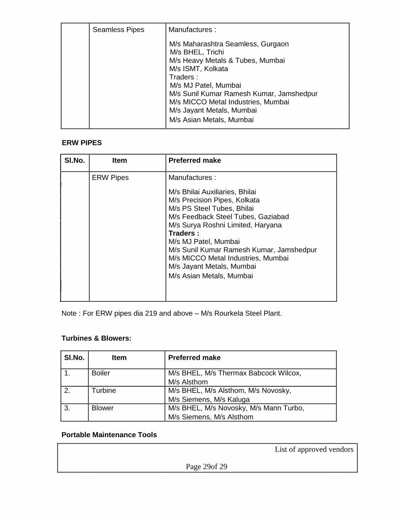
Seamless Pipes Manufactures :
M/s Maharashtra Seamless, Gurgaon M/s BHEL, Trichi M/s Heavy Metals & Tubes, Mumbai M/s ISMT, Kolkata Traders : M/s MJ Patel, Mumbai M/s Sunil Kumar Ramesh Kumar, Jamshedpur M/s MICCO Metal Industries, Mumbai M/s Jayant Metals, Mumbai
M/s Asian Metals, Mumbai
ERW PIPES
Sl.No. Item Preferred make
ERW Pipes Manufactures :
M/s Bhilai Auxiliaries, Bhilai M/s Precision Pipes, Kolkata
M/s PS Steel Tubes, Bhilai
M/s Feedback Steel Tubes, Gaziabad
M/s Surya Roshni Limited, Haryana
Traders :
M/s MJ Patel, Mumbai
M/s Sunil Kumar Ramesh Kumar, Jamshedpur
M/s MICCO Metal Industries, Mumbai
M/s Jayant Metals, Mumbai
M/s Asian Metals, Mumbai
Note : For ERW pipes dia 219 and above – M/s Rourkela Steel Plant.
Turbines & Blowers:
Sl.No. Item Preferred make
1. Boiler M/s BHEL, M/s Thermax Babcock Wilcox,
M/s Alsthom
2. Turbine M/s BHEL, M/s Alsthom, M/s Novosky,
M/s Siemens, M/s Kaluga
3. Blower M/s BHEL, M/s Novosky, M/s Mann Turbo,
M/s Siemens, M/s Alsthom
Portable Maintenance Tools
List of approved vendors
Page 29of 29

A. Electrical equipment.
Items Preferred makes
1. St.Grinder M/s Ralli Wolf 2. Angle Grinders M/s Bosch Power Tools 3. Drilling Machines M/s Kulkarni Power Tools 4. Bench Grinders 6” M/s Black & Decker 5. Sanders/ Polishers
6. Sander
B. Lifting / Pulling Equipments.
Items Preferred makes
1. Pulling and lifting machines M/s Tirfor, M/s Max Pul, M/s Indef 2. Hand Operated chain pulley M/s Indef block.
3. Hand operated gear M/s Indef traveling trolleys.
4. Hydraulic Jacks
a. Remote Controlled type M/s OEW, M/s Orione, M/s Enerpack (operating pressure + 700
bar)
b. Elect. Hydraulic. Power pack M/s OEW, M/s Orione, M/s Enerpack (operating pressure + 700
bar)
5. Hyd. Bearing pullers. M/s Super Unique, M/s Omar Star, M/s
Power Ram
C. Pneumatic Tools
Items Preferred makes
1. Chipping Hammer
2. St.Grinder
3. Angle Grinders M/s CPT 4. Drilling Machine M/s Pne-Tech. 5. Die Grinders
6. Impact Wrenches
D. Miscellaneous Tools
List of approved vendors
Page 30of 30

Items Preferred makes
1. Die less hyd. Crimping tools M/s Ismal make
(6-500 sq.mm size) M/s Taparia, M/s Jhalani 2. Ring Spanners of asserted
sizes. M/s Evarest, M/s Mekaster
3. Socket spanners. M/s Taparia, M/s Mekaster
Bearings.
S.N. Category Suppliers Remarks 1 Category SKF, FAG & TIMKEN Bearings whose
(Supercritic (Overseas manufacturers only) country of origin is
al)(*) China are not
acceptable. 2 Category II SKF, FAG, TIMKEN, NSK, SNR, Bearings whose
(Critical)(*) NTN, KOYO country of origin is
(Overseas/Indigenous China are not
manufacturers) acceptable. 3 Category III SKF, FAG, TIMKEN, NTN. NSK,
(General) SNR, KOYO, ZKL, GPZ, MPZ,
(*) SPZ, URB, ZWZ, INA, NBC, AEC,
ABL, JMC, NRB, ARB (Overseas /
Indigenous manufacturers)
4 Non SPZ, MPZ, GPZ, & ZKL, NTN,
standard NSK, KOYO, URB
Russian (who have already developed
origin (*) certain Russian bearings )
5 Uncommon, IKO, NACHI, ELGES, ASAHI,
Non- FAFNIR , TORRINGTON, UKF,
standard NADELA, RBC, UNIMAC, McGILL,
bearings of HOFFMAN, MRC, NDH, OILITE,
other MATHWS, HOESCH ROTHE
origins: ERDE, ROLLWAY, GAMET,
(*) POLLARD, HYATT, EICH, RHP
and COOPER
6 Sleeves SKF, FAG, TIMKEN, NTN. NSK, If bearing SNR, KOYO, for cat-I and Cat.-II. manufacturers
MIDHA & MIDHA, SIBCO recommend and stand
guarantee for their
bearings.
List of approved vendors
Page 31of 31

(*) Supercritical :
Bearings whose failure can result in stoppage of either upstream or downstream process or
require more than 8 hrs. for restoration of the equipment and the process of the department
is stopped during this period or can result in huge consequential losses are classified as
supercritical bearings. Based on this, 206 sizes are classified as supercritical bearings.
Critical :
Bearings whose failure can result into a stoppage of the process of the shop for less than 8
hours but more than 2 hours or affects downstream or upstream units to some extent are
classified as critical bearings. Based on this, 595 sizes are classified as Critical bearings.
General :
Bearings whose failure can result in stoppage of process for less than 2 hours and
sometimes no process stoppage is required immediately and standby or alternative
arrangements can be made to maintain process continuity are classified as General
purpose bearings. Based on this, 1882 sizes are classified as general purpose bearings.
Non standard Russian origin:
Bearings of supercritical / critical / general nature application supplied alongwith OEMs of
Russian, CIS, or former East Block countries, whose substitutes are not available from
other manufacturers are grouped under this category. 231 sizes are classified in this
category.
Uncommon, Non-standard bearings of other origins:
The varieties of bearings whose consumption pattern is so low that no other manufacturer is
ready to develop alternatives are classified as uncommon, non-standard of other origin. 127
sizes are classified in this category.
Sleeves :
Sleeves are to be procured from bearing manufacturers only for their bearings or from
sources recommended by bearing manufacturers so that performance of bearing is
guaranteed.
Chemicals / Special Material
S.No. Type Standard/ Preferred manufacturers
Specification
1. Admixtures
a. Plasticizer IS 9103 FOSROC, STP, SIKA, PIDILITE,
CICO, MC, BECK
List of approved vendors
Page 32of 32
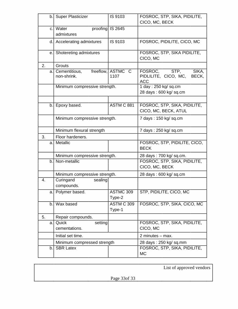
b. Super Plasticizer IS 9103 FOSROC, STP, SIKA, PIDILITE,
CICO, MC, BECK
c. Water proofing IS 2645
admixtures
d. Accelerating admixtures IS 9103 FOSROC, PIDILITE, CICO, MC
e. Shotereting admixtures FOSROC, STP, SIKA PIDILITE,
CICO, MC
2. Grouts
a. Cementitious, freeflow, ASTMC C FOSROC, STP, SIKA,
non-shrink. 1107 PIDLILITE, CICO, MC, BECK,
ACC Minimum compressive strength. 1 day : 250 kg/ sq.cm
28 days : 600 kg/ sq.cm
b. Epoxy based. ASTM C 881 FOSROC, STP, SIKA, PIDILITE,
CICO, MC, BECK, ATUL
Minimum compressive strength. 7 days : 150 kg/ sq.cm
Minimum flexural strength 7 days : 250 kg/ sq.cm
3. Floor hardeners.
a. Metallic FOSROC, STP, PIDILITE, CICO,
BECK
Minimum compressive strength. 28 days : 700 kg/ sq.cm.
b. Non-metallic FOSROC, STP, SIKA, PIDILITE,
CICO, MC, BECK
Minimum compressive strength. 28 days : 600 kg/ sq.cm
4. Curingand sealing
compounds.
a. Polymer based. ASTMC 309 STP, PIDILITE, CICO, MC
Type-2
b. Wax based ASTM C 309 FOSROC, STP, SIKA, CICO, MC
Type-1
5. Repair compounds.
a. Quick setting FOSROC, STP, SIKA, PIDILITE,
cementations. CICO, MC
Initial set time. 2 minutes – max.
Minimum compressed strength 28 days : 250 kg/ sq.mm
b. SBR Latex FOSROC, STP, SIKA, PIDILITE,
MC
List of approved vendors
Page 33of 33

Solid content Not less than 42%
pH value Not less than 10
Density More than 1 kg/ litre.
c. Epoxy bond coat ASTM C FOSROC, STP, SIKA, CICO, 881, MC, BECK, PRODORITE
Type-2
d. SFMC FOSROC, STP, SIKA, PIDILITE,
BECK
Minimum compressive strength. 1 day : 100 kg/ sq.cm
28 days : 500 kg/ sq.cm
6. Epoxy floorings/ coatings.
a. Screed (*) FOSROC, STP, SIKA, PIDILITE,
MC, BECK
b. Self leveling (*) FOSROC, STP, SIKA, PIDILITE,
CICO, MC, BECK, APURVA
c. Epoxy floor coating (*) FOSROC, STP, SIKA, PIDILITE,
MC
7. Protective and water proof
coatings.
a. Epoxy based. ASTM C FOSROC, STP, SIKA, PIDILITE, 881, CICO, MC, BECK, APURVA Type-3, Gr.2
Class-B & C
b. Polymer modified ASTM C 309 FOSROC, STP, SIKA, PIDILITE, cementions. CICO, MC, BECK, PRODORITE,
APURVA
8. Joint sealments IS 12118 FOSROC, STP, SIKA, PIDILITE,
(Polysulphide) (*) CICO
(*) Not recommended for Purchase. Can be applied through contracts including supply
and application of materials as per requirements and manufacturer’s specifications.
Fire Fighting Equipment.
1. Fire Extinguishers and ISO – 9001- M/s Kanadia Fyr Fyter Pvt.Ltd.
Modulars. 2000 Mumbai.
Polymer Chute Liner.
1. Polymer Chute Liner. - M/s Jyoti Cero Rubber,
Jamshedpur.
List of approved vendors
Page 34of 34

***
List of approved vendors
Page 35of 35

GENERAL SPECIFICATION
FOR
PREFFERED MAKES
(Refer enclosed volume - 4 of the tender documents for GS-13 (Preferred makes)
of GTS for Bhilai Steel Plant-SAIL)
Top Related