


Languages
Pages
Legal


2018
2019
CATALOGUE EXTRACT
New range for metering and power monitoring


Contents
Software suite
DIRIS Digiware D and C
DIRIS A-40
DIRIS Q800
DIRIS Digiware S
DIRIS A-20
DIRIS Digiware U
DIRIS A-30 / A-41
DIRIS Digiware I
DIRIS A-10
Single-circuit metering, measurement & analysis
Multi-circuit metering & measurement Current sensors
Quality analyser
Integrated technologies . . . . . . . . . . . . . . . . . . . . . . . . . . . . . . . . . . . . . . . . . . . . . . . . . . . . .
Selection guide measurement and monitoring system for electrical installations AC . . . .
Selection guide measurement and monitoring system for electrical installations DC . . .
Selection guide multifunction meters . . . . . . . . . . . . . . . . . . . . . . . . . . . . . . . . . . . . . . . . . .
Selection guide software solutions . . . . . . . . . . . . . . . . . . . . . . . . . . . . . . . . . . . . . . . . . . . .
Online energy management service N’VIEW
Embedded web serverWEBVIEW
AC current sensorsTE, TR, TF
DC current sensors
DIRIS Digiware AC
DIRIS Digiware DC
DIRIS Digiware Udc
DIRIS Digiware IO
DIRIS Digiware Idc
p. 4
p. 6
p. 12
p. 16
p. 18
p. 80
p. 24 p. 40
p. 82
p. 30
p. 66
p. 36
p. 76
p. 32
p. 72
p. 52
p. 60
p. 48
p. 62
p. 56
p. 20
3Catalogue extract 2018-2019

Products that are setting new standards in measurement accuracy
PreciSense technology ensures 100% reliable accuracy over the entire measuring chain.
Be guaranteed of the accuracy of your measurements: • For the global measurement chain. • For reliable measurements. • For relevant corrective actions.
PreciSense technology offers the best accuracy on the market regardless of the type of current sensors used (closed, split-core, flexible or embedded in the DIRIS Digiware S module).
The simple and cost-saving solution for monitoring your protective devices
Virtual Monitor technology enables a monitoring solution to be installed simply and at all levels of the installation.
Virtual Monitor: • Detects the position and status of the device.
• Detects tripping of the protective device. • Meters the number of operations.
VirtualMonitor technology monitors the status of protective devices: • On your entire electrical installation (without additional space).
• Remotely and in real-time. • Without additional hardware or wiring (without adding an auxiliary contact).
The software that eliminates wiring errors
AutoCorrect technology ensures that the equipment is properly wired at all times, thus avoiding on-site inspections.
AutoCorrect technology ensures the operation of the measuring system thanks to simple and rapid detection of connection errors: • Automatic wiring control (phase sequence detection and automatic configuration of the direction of the current).
• Correction of errors with a single click. • Feature available off-load.
Error correction is carried out without any modification to the wiring.
Discover the video Discover the video Discover the video
SY
DIV
_419
_A
VirtualMonitor AutoCorrectPreciSense
Integrated technologies Groundbreaking technologies for greater simplicity and performance
Mul
ti-ci
rcui
t m
eter
ing
an
d m
easu
rem
ent
• DIRIS Digiware S with its 3 integrated sensors and DIRIS Digiware I associated with iTR sensors.
• DIRIS A-40 with iTR sensors.
Multifunction meters
PreciSense, VirtualMonitor and AutoCorrect technologies are embedded in Socomec’s power monitoring devices.
Power metering and monitoring system for AC electrical installations
Integrated technologiesGroundbreaking technologies for greater simplicity and performance
4 Catalogue extract 2018-2019

Products that are setting new standards in measurement accuracy
PreciSense technology ensures 100% reliable accuracy over the entire measuring chain.
Be guaranteed of the accuracy of your measurements: • For the global measurement chain. • For reliable measurements. • For relevant corrective actions.
PreciSense technology offers the best accuracy on the market regardless of the type of current sensors used (closed, split-core, flexible or embedded in the DIRIS Digiware S module).
The simple and cost-saving solution for monitoring your protective devices
Virtual Monitor technology enables a monitoring solution to be installed simply and at all levels of the installation.
Virtual Monitor: • Detects the position and status of the device.
• Detects tripping of the protective device. • Meters the number of operations.
VirtualMonitor technology monitors the status of protective devices: • On your entire electrical installation (without additional space).
• Remotely and in real-time. • Without additional hardware or wiring (without adding an auxiliary contact).
The software that eliminates wiring errors
AutoCorrect technology ensures that the equipment is properly wired at all times, thus avoiding on-site inspections.
AutoCorrect technology ensures the operation of the measuring system thanks to simple and rapid detection of connection errors: • Automatic wiring control (phase sequence detection and automatic configuration of the direction of the current).
• Correction of errors with a single click. • Feature available off-load.
Error correction is carried out without any modification to the wiring.
Discover the video Discover the video Discover the video
SY
DIV
_419
_A
VirtualMonitor AutoCorrectPreciSense
Integrated technologies Groundbreaking technologies for greater simplicity and performance
Mul
ti-ci
rcui
t m
eter
ing
an
d m
easu
rem
ent
• DIRIS Digiware S with its 3 integrated sensors and DIRIS Digiware I associated with iTR sensors.
• DIRIS A-40 with iTR sensors.
Multifunction meters
PreciSense, VirtualMonitor and AutoCorrect technologies are embedded in Socomec’s power monitoring devices.
Power metering and monitoring system for AC electrical installations
Integrated technologiesGroundbreaking technologies for greater simplicity and performance
5Catalogue extract 2018-2019

Build your own AC system
Find the best DIRIS Digiware configuration!
Control and power supply interface (24 VDC)
DIRIS Digiware D with display
DIRIS Digiware C without screen
DIRIS Digiware U-x
Voltage acquisition module
DIRIS Digiware S
Current acquisition module with integrated sensors
+ +or
DIRIS Digiware IO-x
Digital and analog input/output modules
+ ++
DIRIS Digiware I-3x
3 inputs
DIRIS Digiware I-4x
4 inputs
DIRIS Digiware I-6x
6 inputs
Current acquisition modules Current sensors
TESolid
TRSplit-core
TFFlexible
The Socomec Meter Selector is your digital assistant, helping you find the best DIRIS Digiware configuration for your energy performance projects, and all in just a few clicks! • Fill in information regarding your project. • Download the electrical diagram and bill of material. • Find all your archived projects in your personal account.
Selection guideMeasurement and monitoring system for electrical installationsDIRIS Digiware
Mul
ti-ci
rcui
t m
eter
ing
&
mea
sure
men
t
Application Centralisation and display of data Data centralisation Repeater
DIRIS Digiware D-40 D-50 D-70 C-31 C-32
FunctionCentralising measurement points: • • • • •
High-resolution LCD display (configuration, selection and visualisation display of circuits) • • •
Repeater •
Power supply24 VDC • • • • •
CommunicationRS485 Modbus output input input •
Bus Digiware • • • • •
Ethernet Modbus TCPModbus TCP
BACnet IPSNMP
Embedded web server •
Control and power supply interface
Application Metering Monitoring Analysis
DIRIS Digiware U U-10 U-20 U-30
Multi-measurementU12, U23, U31, V1, V2, V3, f • • •
U system, V system •
Ph/N unbalance •
Ph/Ph unbalance •
Quality analysisTHDv1, THDv2, THDv3, THDu12, THDu23, THDu31 • •
Crest factors V1, V2, V3, U12, U23, U31 •
Individual harmonics U & V (up to rank 63) •
Voltage dips, cutoffs and surges (EN50160) •
AlarmsOn threshold •
HistoryAverage values •
FormatWidth/number of modules 18 mm / 1 18 mm / 1 18 mm / 1
Voltage acquisition module
Selection guideMeasurement and monitoring system for electrical installations
DIRIS Digiware
6 Catalogue extract 2018-2019

Build your own AC system
Find the best DIRIS Digiware configuration!
Control and power supply interface (24 VDC)
DIRIS Digiware D with display
DIRIS Digiware C without screen
DIRIS Digiware U-x
Voltage acquisition module
DIRIS Digiware S
Current acquisition module with integrated sensors
+ +or
DIRIS Digiware IO-x
Digital and analog input/output modules
+ ++
DIRIS Digiware I-3x
3 inputs
DIRIS Digiware I-4x
4 inputs
DIRIS Digiware I-6x
6 inputs
Current acquisition modules Current sensors
TESolid
TRSplit-core
TFFlexible
The Socomec Meter Selector is your digital assistant, helping you find the best DIRIS Digiware configuration for your energy performance projects, and all in just a few clicks! • Fill in information regarding your project. • Download the electrical diagram and bill of material. • Find all your archived projects in your personal account.
Selection guideMeasurement and monitoring system for electrical installationsDIRIS Digiware
Mul
ti-ci
rcui
t m
eter
ing
&
mea
sure
men
t
Application Centralisation and display of data Data centralisation Repeater
DIRIS Digiware D-40 D-50 D-70 C-31 C-32
FunctionCentralising measurement points: • • • • •
High-resolution LCD display (configuration, selection and visualisation display of circuits) • • •
Repeater •
Power supply24 VDC • • • • •
CommunicationRS485 Modbus output input input •
Bus Digiware • • • • •
Ethernet Modbus TCPModbus TCP
BACnet IPSNMP
Embedded web server •
Control and power supply interface
Application Metering Monitoring Analysis
DIRIS Digiware U U-10 U-20 U-30
Multi-measurementU12, U23, U31, V1, V2, V3, f • • •
U system, V system •
Ph/N unbalance •
Ph/Ph unbalance •
Quality analysisTHDv1, THDv2, THDv3, THDu12, THDu23, THDu31 • •
Crest factors V1, V2, V3, U12, U23, U31 •
Individual harmonics U & V (up to rank 63) •
Voltage dips, cutoffs and surges (EN50160) •
AlarmsOn threshold •
HistoryAverage values •
FormatWidth/number of modules 18 mm / 1 18 mm / 1 18 mm / 1
Voltage acquisition module
Selection guideMeasurement and monitoring system for electrical installations
DIRIS Digiware
7Catalogue extract 2018-2019
p. 24
p. 30
p. 24 p. 24
p. 30
p. 24
p. 30
p. 24
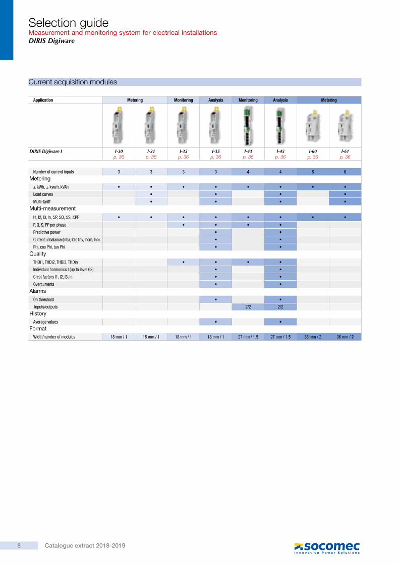
Application Metering Monitoring Analysis Monitoring Analysis Metering
DIRIS Digiware I I-30 I-31 I-33 I-35 I-43 I-45 I-60 I-61
Number of current inputs 3 3 3 3 4 4 6 6
Metering± kWh, ± kvarh, kVAh • • • • • • • •
Load curves • • • •
Multi-tariff • • • •
Multi-measurement
I1, I2, I3, In, ΣP, ΣQ, ΣS, ΣPF • • • • • • • •
P, Q, S, PF per phase • • • •
Predictive power • •
Current unbalance (Inba, Idir, Iinv, Ihom, Inb) • •
Phi, cos Phi, tan Phi • •
QualityTHDi1, THDi2, THDi3, THDin • • • •
Individual harmonics I (up to level 63) • •
Crest factors l1, l2, l3, ln • •
Overcurrents • •
AlarmsOn threshold • •
Inputs/outputs 2/2 2/2
HistoryAverage values • •
FormatWidth/number of modules 18 mm / 1 18 mm / 1 18 mm / 1 18 mm / 1 27 mm / 1.5 27 mm / 1.5 36 mm / 2 36 mm / 2
Current acquisition modules
Selection guideMeasurement and monitoring system for electrical installationsDIRIS Digiware
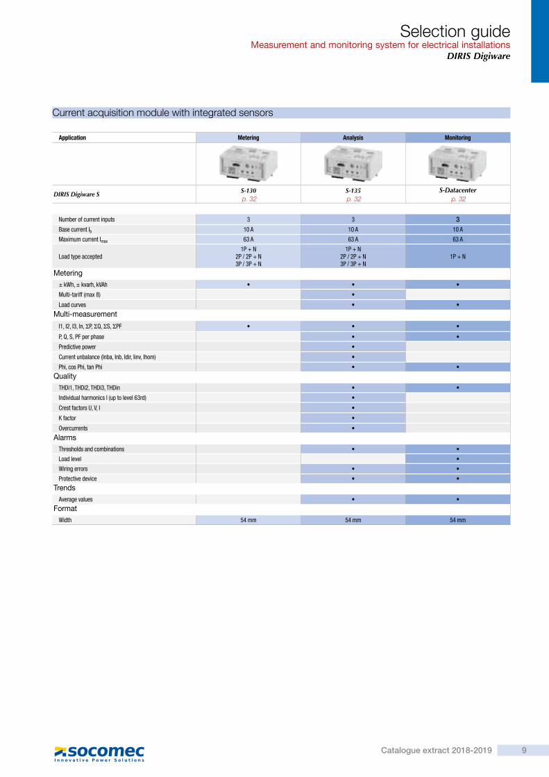
Current acquisition module with integrated sensors
Application Metering Analysis Monitoring
DIRIS Digiware S S-130 S-135 S-Datacenter
Number of current inputs 3 3 3Base current Ib 10 A 10 A 10 A
Maximum current Imax 63 A 63 A 63 A
Load type accepted1P + N
2P / 2P + N3P / 3P + N
1P + N2P / 2P + N3P / 3P + N
1P + N
Metering± kWh, ± kvarh, kVAh • • •
Multi-tariff (max 8) •
Load curves • •
Multi-measurement
I1, I2, I3, In, ΣP, ΣQ, ΣS, ΣPF • • •
P, Q, S, PF per phase • •
Predictive power •
Current unbalance (Inba, Inb, Idir, Iinv, Ihom) •
Phi, cos Phi, tan Phi • •
QualityTHDi1, THDi2, THDi3, THDin • •
Individual harmonics I (up to level 63rd) •
Crest factors U, V, I •
K factor •
Overcurrents •
AlarmsThresholds and combinations • •
Load level •
Wiring errors • •
Protective device • •
TrendsAverage values • •
FormatWidth 54 mm 54 mm 54 mm
Selection guideMeasurement and monitoring system for electrical installations
DIRIS Digiware
8 Catalogue extract 2018-2019
p. 36 p. 36 p. 36 p. 36 p. 36 p. 36 p. 36 p. 36
Application Metering Monitoring Analysis Monitoring Analysis Metering
DIRIS Digiware I I-30 I-31 I-33 I-35 I-43 I-45 I-60 I-61
Number of current inputs 3 3 3 3 4 4 6 6
Metering± kWh, ± kvarh, kVAh • • • • • • • •
Load curves • • • •
Multi-tariff • • • •
Multi-measurement
I1, I2, I3, In, ΣP, ΣQ, ΣS, ΣPF • • • • • • • •
P, Q, S, PF per phase • • • •
Predictive power • •
Current unbalance (Inba, Idir, Iinv, Ihom, Inb) • •
Phi, cos Phi, tan Phi • •
QualityTHDi1, THDi2, THDi3, THDin • • • •
Individual harmonics I (up to level 63) • •
Crest factors l1, l2, l3, ln • •
Overcurrents • •
AlarmsOn threshold • •
Inputs/outputs 2/2 2/2
HistoryAverage values • •
FormatWidth/number of modules 18 mm / 1 18 mm / 1 18 mm / 1 18 mm / 1 27 mm / 1.5 27 mm / 1.5 36 mm / 2 36 mm / 2
Current acquisition modules
Selection guideMeasurement and monitoring system for electrical installationsDIRIS Digiware
Current acquisition module with integrated sensors
Application Metering Analysis Monitoring
DIRIS Digiware S S-130 S-135 S-Datacenter
Number of current inputs 3 3 3Base current Ib 10 A 10 A 10 A
Maximum current Imax 63 A 63 A 63 A
Load type accepted1P + N
2P / 2P + N3P / 3P + N
1P + N2P / 2P + N3P / 3P + N
1P + N
Metering± kWh, ± kvarh, kVAh • • •
Multi-tariff (max 8) •
Load curves • •
Multi-measurement
I1, I2, I3, In, ΣP, ΣQ, ΣS, ΣPF • • •
P, Q, S, PF per phase • •
Predictive power •
Current unbalance (Inba, Inb, Idir, Iinv, Ihom) •
Phi, cos Phi, tan Phi • •
QualityTHDi1, THDi2, THDi3, THDin • •
Individual harmonics I (up to level 63rd) •
Crest factors U, V, I •
K factor •
Overcurrents •
AlarmsThresholds and combinations • •
Load level •
Wiring errors • •
Protective device • •
TrendsAverage values • •
FormatWidth 54 mm 54 mm 54 mm
Selection guideMeasurement and monitoring system for electrical installations
DIRIS Digiware
9Catalogue extract 2018-2019
p. 32 p. 32 p. 32

Suitable for existing installations with space restrictions or with a high-intensity current
Flexible current sensors
TF-55 TF-120 TF-300
Nominal current In (A) 150 … 6000 150 … 600 500 … 2000 1600 … 6000
Actual coverage range (A) 3 … 7200 3 … 720 10 … 2400 32 … 7200
Aperture (mm) Ø 55 Ø 120 Ø 300Connection RJ12 RJ12 RJ12
Suitable for new installations match the pitch of protective devices
Solid-core current sensors
TE-18 TE-25 TE-35 TE-45 TE-55 TE-90
Nominal current In (A) 5 … 2000 5 … 20 25 … 63 40 … 160 63 … 250 160 … 630 400 … 1000 600 … 2000
Actual coverage range (A) 0.1 … 2400 0.1 … 24 0.5 … 75.6 0.8 … 192 1.26 … 300 3.2 … 756 8 … 1200 12 … 2400
Aperture (mm) Ø 8.4 Ø 8.4 13.5 x 13.5 21 x 21 31 x 31 41 x 41 64 x 64Dimensions (mm) 28 x 20 x 45 28 x 20 x 45 25 x 32.5 x 65 35 x 32.5 x 71 45 x 32.5 x 86 55 x 32.5 x 100 90 x 126 x 24.6Connection RJ12 RJ12 RJ12 RJ12 RJ12 RJ12 RJ12
For demands greater than 2000 A, the 5 A / RJ12 adapter guarantees the compatibility of the TCs.
Current sensors
Suitable for existing installations
Split-core current sensors
TR / iTR-10 TR / iTR-14 TR / iTR-21 TR / iTR-32
Nominal current In (A) 25 … 600 25 … 63 40 … 160 63 … 250 160 … 600
Actual coverage range (A) 0.5 … 720 0.5 ... 90 0.64 ... 120 1.26 ... 200 4 ... 720
Aperture (mm) Ø 10 Ø 14 Ø 21 Ø 32Dimensions (mm) 26 x 44 x 28 29 x 67 x 28 37 x 65 x 43 53 x 86 x 47Connection RJ12 RJ12 RJ12 RJ12
For demands greater than 600 A, the 5 A / RJ12 adapter guarantees the compatibility of the TCs.
Selection guideMeasurement and monitoring system for electrical installationsDIRIS Digiware
Input/output modules
Application Comptage / surveillance / pilotage
DIRIS Digiware IO IO-10 IO-20
Number of digital inputs/outputs 4 / 2
Number of analog inputs 2Format
Width/number of modules 18 mm / 1 18 mm / 1
Selection guideMeasurement and monitoring system for electrical installations
DIRIS Digiware
10 Catalogue extract 2018-2019
p. 40 p. 40 p. 40 p. 40 p. 40 p. 40
p. 44p. 44p. 44p. 44
p. 46 p. 46 p. 46

Suitable for existing installations with space restrictions or with a high-intensity current
Flexible current sensors
TF-55 TF-120 TF-300
Nominal current In (A) 150 … 6000 150 … 600 500 … 2000 1600 … 6000
Actual coverage range (A) 3 … 7200 3 … 720 10 … 2400 32 … 7200
Aperture (mm) Ø 55 Ø 120 Ø 300Connection RJ12 RJ12 RJ12
Suitable for new installations match the pitch of protective devices
Solid-core current sensors
TE-18 TE-25 TE-35 TE-45 TE-55 TE-90
Nominal current In (A) 5 … 2000 5 … 20 25 … 63 40 … 160 63 … 250 160 … 630 400 … 1000 600 … 2000
Actual coverage range (A) 0.1 … 2400 0.1 … 24 0.5 … 75.6 0.8 … 192 1.26 … 300 3.2 … 756 8 … 1200 12 … 2400
Aperture (mm) Ø 8.4 Ø 8.4 13.5 x 13.5 21 x 21 31 x 31 41 x 41 64 x 64Dimensions (mm) 28 x 20 x 45 28 x 20 x 45 25 x 32.5 x 65 35 x 32.5 x 71 45 x 32.5 x 86 55 x 32.5 x 100 90 x 126 x 24.6Connection RJ12 RJ12 RJ12 RJ12 RJ12 RJ12 RJ12
For demands greater than 2000 A, the 5 A / RJ12 adapter guarantees the compatibility of the TCs.
Current sensors
Suitable for existing installations
Split-core current sensors
TR / iTR-10 TR / iTR-14 TR / iTR-21 TR / iTR-32
Nominal current In (A) 25 … 600 25 … 63 40 … 160 63 … 250 160 … 600
Actual coverage range (A) 0.5 … 720 0.5 ... 90 0.64 ... 120 1.26 ... 200 4 ... 720
Aperture (mm) Ø 10 Ø 14 Ø 21 Ø 32Dimensions (mm) 26 x 44 x 28 29 x 67 x 28 37 x 65 x 43 53 x 86 x 47Connection RJ12 RJ12 RJ12 RJ12
For demands greater than 600 A, the 5 A / RJ12 adapter guarantees the compatibility of the TCs.
Selection guideMeasurement and monitoring system for electrical installationsDIRIS Digiware
Input/output modules
Application Comptage / surveillance / pilotage
DIRIS Digiware IO IO-10 IO-20
Number of digital inputs/outputs 4 / 2
Number of analog inputs 2Format
Width/number of modules 18 mm / 1 18 mm / 1
Selection guideMeasurement and monitoring system for electrical installations
DIRIS Digiware
11Catalogue extract 2018-2019
p. 60 p. 60
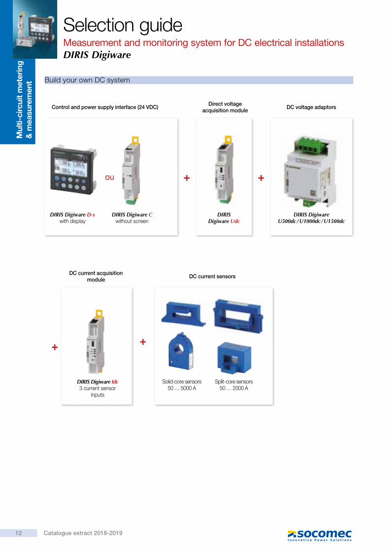
Control and power supply interface (24 VDC)
DIRIS Digiware D-x with display
DIRIS Digiware C without screen
DIRIS Digiware Udc
Direct voltage acquisition module
DIRIS Digiware U500dc / U1000dc / U1500dc
DC voltage adaptors
+ +ou
+ +
DIRIS Digiware Idc 3 current sensor
inputs
DC current acquisition module
Build your own DC system
DC current sensors
Solid-core sensors50 … 5000 a
Split-core sensors50 … 2000 a
Selection guideMeasurement and monitoring system for DC electrical installationsDIRIS Digiware
Mul
ti-ci
rcui
t m
eter
ing
&
mea
sure
men
t
Application Centralisation and display of data Data centralisation Repeater
DIRIS Digiware D-40 D-50 D-70 C-31 C-32
FunctionCentralising measurement points • • • • •
High-resolution LCD display (configuration, selection and visualisation display of circuits) • • •
Repeater •
Power supply24 VDC • • • • •
CommunicationRS485 Modbus OUT IN IN •
Digiware Bus • • • • •
Ethernet Modbus TCPModbus TCP
BACnet IPSNMP
Embedded web server •
Control and power supply interface
Selection guideMeasurement and monitoring system for DC electrical installations
DIRIS Digiware
12 Catalogue extract 2018-2019

Control and power supply interface (24 VDC)
DIRIS Digiware D-x with display
DIRIS Digiware C without screen
DIRIS Digiware Udc
Direct voltage acquisition module
DIRIS Digiware U500dc / U1000dc / U1500dc
DC voltage adaptors
+ +ou
+ +
DIRIS Digiware Idc 3 current sensor
inputs
DC current acquisition module
Build your own DC system
DC current sensors
Solid-core sensors50 … 5000 a
Split-core sensors50 … 2000 a
Selection guideMeasurement and monitoring system for DC electrical installationsDIRIS Digiware
Mul
ti-ci
rcui
t m
eter
ing
&
mea
sure
men
t
Application Centralisation and display of data Data centralisation Repeater
DIRIS Digiware D-40 D-50 D-70 C-31 C-32
FunctionCentralising measurement points • • • • •
High-resolution LCD display (configuration, selection and visualisation display of circuits) • • •
Repeater •
Power supply24 VDC • • • • •
CommunicationRS485 Modbus OUT IN IN •
Digiware Bus • • • • •
Ethernet Modbus TCPModbus TCP
BACnet IPSNMP
Embedded web server •
Control and power supply interface
Selection guideMeasurement and monitoring system for DC electrical installations
DIRIS Digiware
13Catalogue extract 2018-2019
p. 24 p. 24 p. 24 p. 24 p. 24

Direct voltage acquisition module (DC)
Application DC voltage measurement
DIRIS Digiware UdcU-31dc U-32dc
Nominal voltage range 24 … 48 VDC 60 … 150 VDC
Measuring range (min-max) 19,2 … 60 VDC 48 … 180 VDC
Multi-measurement
DC voltage (VDC) • •
Power quality
V ripple (voltage ripple) • •
Vrms • •Alarms
Thresholds and combinations • •Trends
Average values • •Format
Width/number of modules 18 mm / 1
Application DC voltage adaptors
DIRIS Digiware UdcU500dc U1000dc U1500dc
Max. voltage range 200 … 600 VDC 400 … 1200 VDC 1200 … 1650 VDC
Association
U-32dc • • •Format
Width/number of modules 54 mm / 3
Selection guideMeasurement and monitoring system for DC electrical installationsDIRIS Digiware
Modules d’acquisition du courant continu (DC)
Application Direct current (DC) measurement modules
DIRIS Digiware IdcI-30dc I-35dc
Number of current inputs3 3
Metering± kWh • •
Load curves •
Multi-measurement
DC current (I DC) • •
DC power (P DC) • •
Predictive power •
Measurement of current qualityI ripple (current ripple) •
I rms •
AlarmsThresholds and combinations •
TrendsAverage values •
FormatWidth/number of modules 18 mm / 1
DC current sensors
tor
e_0
71_a
.ep
S
tor
e_0
72_a
.ep
S
DC current sensors measure the load currents of a DC electrical installation and transmit the information to DIrIS Digiware Idc modules via a quick rJ12 connection with color-coded cables for an easy identification of circuits.the range comprises solid-core and split-core sensors, from 50 to 5000 a in various sizes, suitable for new or retrofit applications.
• easy connection to prevent wiring errors. • Up to 3 sensors on each DIrIS Digiware Idc measurement module.
Selection guideMeasurement and monitoring system for DC electrical installations
DIRIS Digiware
14 Catalogue extract 2018-2019
p. 48 p. 48
p. 48 p. 48 p. 48

Direct voltage acquisition module (DC)
Application DC voltage measurement
DIRIS Digiware UdcU-31dc U-32dc
Nominal voltage range 24 … 48 VDC 60 … 150 VDC
Measuring range (min-max) 19,2 … 60 VDC 48 … 180 VDC
Multi-measurement
DC voltage (VDC) • •
Power quality
V ripple (voltage ripple) • •
Vrms • •Alarms
Thresholds and combinations • •Trends
Average values • •Format
Width/number of modules 18 mm / 1
Application DC voltage adaptors
DIRIS Digiware UdcU500dc U1000dc U1500dc
Max. voltage range 200 … 600 VDC 400 … 1200 VDC 1200 … 1650 VDC
Association
U-32dc • • •Format
Width/number of modules 54 mm / 3
Selection guideMeasurement and monitoring system for DC electrical installationsDIRIS Digiware
Modules d’acquisition du courant continu (DC)
Application Direct current (DC) measurement modules
DIRIS Digiware IdcI-30dc I-35dc
Number of current inputs3 3
Metering± kWh • •
Load curves •
Multi-measurement
DC current (I DC) • •
DC power (P DC) • •
Predictive power •
Measurement of current qualityI ripple (current ripple) •
I rms •
AlarmsThresholds and combinations •
TrendsAverage values •
FormatWidth/number of modules 18 mm / 1
DC current sensors
tor
e_0
71_a
.ep
S
tor
e_0
72_a
.ep
S
DC current sensors measure the load currents of a DC electrical installation and transmit the information to DIrIS Digiware Idc modules via a quick rJ12 connection with color-coded cables for an easy identification of circuits.the range comprises solid-core and split-core sensors, from 50 to 5000 a in various sizes, suitable for new or retrofit applications.
• easy connection to prevent wiring errors. • Up to 3 sensors on each DIrIS Digiware Idc measurement module.
Selection guideMeasurement and monitoring system for DC electrical installations
DIRIS Digiware
15Catalogue extract 2018-2019
p. 52 p. 52
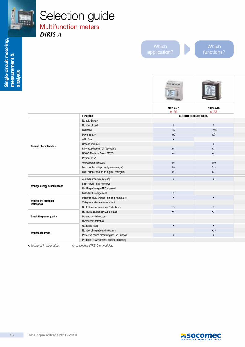
Which application?
Which functions?
DIRIS A-10 DIRIS A-20 DIRIS A-30DIRIS A-40
ModbusDIRIS A-40
Modbus + ProfibusDIRIS A-40
Modbus + Ethernet
Functions CURRENT TRANSFORMERS CURRENT TRANSFORMERS SMART SENSORS
General characteristics
Remote display
Number of loads 1 1 1 1
Mounting DIN 96*96 96*96 96*96
Power supply AC AC AC / DC AC
All In One • •
Optional modules • •
Ethernet (Modbus TCP / Bacnet IP) o / - o / - o / - - / - - / - • / •
RS485 (Modbus / Bacnet MSTP) • / - •/ - • / - • / - • / - • / -
Profibus DPV1 o - • -
Webserver / File export o / - o / o o / o o / o o / o • /•
Max. number of inputs (digital / analogue) 1 / - 3 / - 6 / 4 3 / -
Max. number of outputs (digital / analogue) 1 / - 1 / - 6 / 4 2 / -
Manage energy consumptions
4-quadrant energy metering • • • •
Load curves (local memory) o •
Rebilling of energy (MID approved)
Multi-tariff management 2 4
Monitor the electrical installation
Instantaneous, average, min and max values • • • •
Voltage unbalance measurement • •
Neutral current (measured / calculated) - / • - / • - / • - / •
Check the power quality
Harmonic analysis (THD / Individual) • / - • / - •/• • / •
Dip and swell detection •
Overcurrent detection •
Manage the loads
Operating hours • • • •
Number of operations (info / alarm) • / - • / - • / •
Protective device monitoring (on / off / tripped) • • • •
Predictive power analysis and load shedding • •
•: integrated in the product. o: optional via DIRIS-G or modules.
Selection guideMultifunction metersDIRIS A
Sing
le-c
ircui
t met
erin
g,
mea
sure
men
t &
anal
ysis
16 Catalogue extract 2018-2019
p. 76 p. 72

Selection guideMultifunction meters
DIRIS A
Which dimensions?
Which communication
protocol?
Which options?
DIRIS A-10 DIRIS A-20 DIRIS A-30DIRIS A-40
ModbusDIRIS A-40
Modbus + ProfibusDIRIS A-40
Modbus + Ethernet
Functions CURRENT TRANSFORMERS CURRENT TRANSFORMERS SMART SENSORS
General characteristics
Remote display
Number of loads 1 1 1 1
Mounting DIN 96*96 96*96 96*96
Power supply AC AC AC / DC AC
All In One • •
Optional modules • •
Ethernet (Modbus TCP / Bacnet IP) o / - o / - o / - - / - - / - • / •
RS485 (Modbus / Bacnet MSTP) • / - •/ - • / - • / - • / - • / -
Profibus DPV1 o - • -
Webserver / File export o / - o / o o / o o / o o / o • /•
Max. number of inputs (digital / analogue) 1 / - 3 / - 6 / 4 3 / -
Max. number of outputs (digital / analogue) 1 / - 1 / - 6 / 4 2 / -
Manage energy consumptions
4-quadrant energy metering • • • •
Load curves (local memory) o •
Rebilling of energy (MID approved)
Multi-tariff management 2 4
Monitor the electrical installation
Instantaneous, average, min and max values • • • •
Voltage unbalance measurement • •
Neutral current (measured / calculated) - / • - / • - / • - / •
Check the power quality
Harmonic analysis (THD / Individual) • / - • / - •/• • / •
Dip and swell detection •
Overcurrent detection •
Manage the loads
Operating hours • • • •
Number of operations (info / alarm) • / - • / - • / •
Protective device monitoring (on / off / tripped) • • • •
Predictive power analysis and load shedding • •
17Catalogue extract 2018-2019
p. 66 p. 62p. 62p. 62

WEBVIEW-S WEBVIEW-M WEBVIEW-L N'VIEW
Hosting of the application(1) DIRIS A-40 Ethernet DIRIS G DIRIS Digiware D-70 DATALOG H80/H81 Cloud
Data collection
Maximum number of connected measurement devices 1 32 32 100 (WEBVIEW-L100)
200 (WEBVIEW-L200) Unlimited
Import of data from files •
Interfacing to third-party applications via connector via connector
Export of data in CSV format • DIRIS G-50/G-60 • • •
Real time monitoring
U/V voltages and currents I • • • • n/a(2)
Powers P, Q, S, Power factor • • • • n/a(2)
Quality monitoring THDi, THDu, THDv, K factor,Harmonic analysis up to 63rd • • • • n/a(2)
Energy metering Ea+, Ea-, Er+, Er-, Es • • • • n/a(2)
Pulse counting • • • • n/a(2)
Input/Output monitoring • • • • n/a(2)
Measurement history U, V, I, P, Q, S, • DIRIS G-50/G-60 • • n/a(2)
Energy analysis
Energy consumption analysis • DIRIS G-50/G-60 • • •
Multi-parameter analysis • •
Compare time periods •
Active energy analysis •
Power demand analysis •
Cost analysis •
Energy performance indicators •
Linear regression •
Measurement and verification (IPMVP method) •
Predictive energy consumption •
Alarm management
Product alarms • • • •
Software alarms •
Alarms history • • • • •
Transmission of alarms e-mail e-mail e-mail e-mail e-mail and SMS
Reporting management
Creation of customised reports •
Automatic dispatch of reports by e-mail •
Creation of customised dashboards •
Site mapping Via Google Maps
Customisable user interface Photoview Photoview Synoptic App
Hierarchy management DIRIS G-50/G-60 • • •
Conformity to standards
Energy Server Standard - IEC 62974-1 • • •
(1) For more information on the hardware please refer to the appropriate catalogue pages.(2) N’VIEW is a software solution intended for energy management purposes only.
What are the features?
Where is the data stored?
For what size of project?
Selection guideSoftware solutions for energy monitoring and analysis
So
ftw
are
suit
e
18 Catalogue extract 2018-2019
p. 80 p. 80 p. 80 p. 80 p. 82

Architecture
SO
FT_0
60_B
_EN
Ethernet
Ethernet
Isolated or single metering points DIRIS Digiware measurement systemmulti-point and multi-fluid
Other devices connected to Modbus
Level 1PMD & sensors
Level 2Local communication network (LAN)
Level 3Long-distance communication network (WAN)
Level 4Cloud hosting
COUNTIS E Ci3
N'VIEWCloud hosting
Lan/Wan
Multi-fluid pulsed meteringand analogue inputs
RS485
Pulse
Ethernet
DIRIS A COUNTIS ECOUNTIS ECix
DATALOG H80
RS485
3G
Digiware Bus
COUNTIS E Ci3
DIRIS A-40
DIRIS G
WEBVIEW-L
WEBVIEW-M
WEBVIEW-MWEBVIEW-S
DIRIS Digiware D-70
DIRIS Digiware
Expert Services
Require integration onto your network?No problem for our Expert Services team. They work out all the details of the measurement schedule, the complete integration of all devices in your energy management system, the configuration of your software application, the training of your teams and details of operational support. For further information, please contact your nearest Socomec office.
Selection guideSoftware solutions for energy monitoring and analysis
19Catalogue extract 2018-2019
Sing
le-c
ircui
t met
erin
g,
mea
sure
men
t &
anal
ysis
diris
-q_0
12_a
DIRIS Q
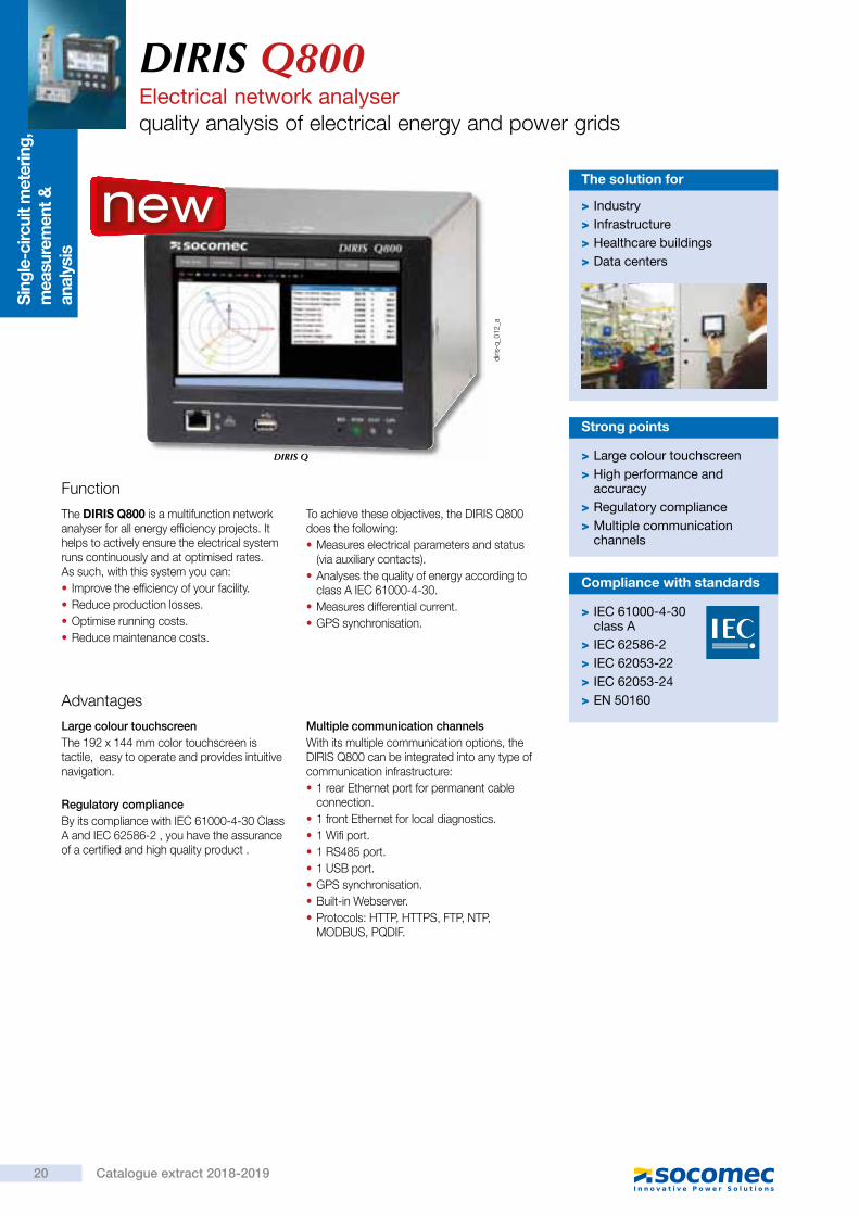
DIRIS Q800Electrical network analyserquality analysis of electrical energy and power grids
Function
The DIRIS Q800 is a multifunction network analyser for all energy efficiency projects. It helps to actively ensure the electrical system runs continuously and at optimised rates. As such, with this system you can: • Improve the efficiency of your facility. • Reduce production losses. • Optimise running costs. • Reduce maintenance costs.
To achieve these objectives, the DIRIS Q800 does the following: • Measures electrical parameters and status (via auxiliary contacts).
• Analyses the quality of energy according to class A IEC 61000-4-30.
• Measures differential current. • GPS synchronisation.
> Large colour touchscreen > High performance and accuracy
> Regulatory compliance > Multiple communication channels
Strong points
Advantages
Large colour touchscreenThe 192 x 144 mm color touchscreen is tactile, easy to operate and provides intuitive navigation.
Regulatory complianceBy its compliance with IEC 61000-4-30 Class A and IEC 62586-2 , you have the assurance of a certified and high quality product .
Multiple communication channelsWith its multiple communication options, the DIRIS Q800 can be integrated into any type of communication infrastructure: • 1 rear Ethernet port for permanent cable connection.
• 1 front Ethernet for local diagnostics. • 1 Wifi port. • 1 RS485 port. • 1 USB port. • GPS synchronisation. • Built-in Webserver. • Protocols: HTTP, HTTPS, FTP, NTP, MODBUS, PQDIF.
> Industry > Infrastructure > Healthcare buildings > Data centers
The solution for
> IEC 61000-4-30 class A
> IEC 62586-2 > IEC 62053-22 > IEC 62053-24 > EN 50160
Compliance with standards
new
DIRIS Q800Electrical network analyser
quality analysis of electrical energy and power grids
Specifications
Functions
Dimensions
Measurements
• Measures across 4 quadrants • Voltage by phase, current by phase, frequency. • Neutral current, differential current. • Neutral/earth voltage. • Active, reactive and apparent power. • Cos phi and power factor. • THD and spectral analysis up to the 63rd for current and voltage. • Flicker (Pst, Plt). • Voltage imbalance. • Remote control signals.
Logging
• EN 50160 events ½ period (10 ms): voltage dips, voltage cutouts, voltage surges.
• Data exported automatically via FTP. • EN50160 compliant. • Transients (20 micro seconds).
Inputs/outputs • 4 digital inputs. • 4 digital outputs. • 4 analogue outputs.
Auxiliary power supply
Voltage range 100 ... 240 VAC / 65 … 250 VDCFrequency 50/60 HzPower consumption Max. 15 VABackup battery Li-ion 2500 mAh (>15 min autonomy)
Measurement inputs
Direct voltage measurement input P-N: max 580 V RMS CAT IIIL-L: max 1000 V RMS CAT III
U4 direct voltage measurement input Max 580 V RMS CAT IIVoltage input crest factor 2Current inputs Max 7 A RMSCurrent input consumption 0.04 VACurrent input crest factor 3Voltage input impedance › 6 MΩFrequency range 42.5 to 57.5 Hz/51 to 69 HzVoltage reference channel U1N/U12Sampling 51.2 kHz @50 Hz
Accuracy
Three-phase voltage ± 0.1% 4th voltage (neutral/earth) ± 0.2%Currents ± 0.2%Power ± 0.2%Frequency ± 10 mHzHarmonics lC. 1 IEC/EN 61000-4-7Active energy lC. 0.5S IEC/EN 62053-22Reactive energy lC. 1 IEC/EN 62053-24
Communication
Ethernet ports 2 Auto MDIX RJ45 10/100 Base EthernetRS485 opto-insulated port (slave) 0.5 UL 4800 to 115200 bpsPassive WIFI antenna RP-SMA femaleActive GPS antenna SMA female
Protocols HTTP, HTTPS, FTP, SFTP, NTP, NMEA, Modbus RTU/TCP
USB port USB 2.0
Environmental conditions
Operating temperature (max. range) -25 … +55°CStorage temperature -25 … +75°C Humidity Max. 95 %Max.altitude 2000 m
Standards and safety
Product comformity IEC/EN 62586-2Safety EN 61010-2-030Degree of pollution 2 (EN 61010-1)Degree of protection IP40 front, IP20 rear
Directive RED §3.1a Health EN 62311 :2008RED § 3.1b EMC
References
Designation ReferenceDIRIS Q800 4826 0100
Dimensions
Cutout 192 x 144 DIN / 186 x 138 mm
Front panel (L x H) 191 x 143 mmEnclosures (L x H x P) 183 x 135 x 190 mmWeight 1400 g
diris
_935
_c_1
_cat
206191
183
135
6
143
20 Catalogue extract 2018-2019

Sing
le-c
ircui
t met
erin
g,
mea
sure
men
t &
anal
ysis
diris
-q_0
12_a
DIRIS Q
DIRIS Q800Electrical network analyserquality analysis of electrical energy and power grids
Function
The DIRIS Q800 is a multifunction network analyser for all energy efficiency projects. It helps to actively ensure the electrical system runs continuously and at optimised rates. As such, with this system you can: • Improve the efficiency of your facility. • Reduce production losses. • Optimise running costs. • Reduce maintenance costs.
To achieve these objectives, the DIRIS Q800 does the following: • Measures electrical parameters and status (via auxiliary contacts).
• Analyses the quality of energy according to class A IEC 61000-4-30.
• Measures differential current. • GPS synchronisation.
> Large colour touchscreen > High performance and accuracy
> Regulatory compliance > Multiple communication channels
Strong points
Advantages
Large colour touchscreenThe 192 x 144 mm color touchscreen is tactile, easy to operate and provides intuitive navigation.
Regulatory complianceBy its compliance with IEC 61000-4-30 Class A and IEC 62586-2 , you have the assurance of a certified and high quality product .
Multiple communication channelsWith its multiple communication options, the DIRIS Q800 can be integrated into any type of communication infrastructure: • 1 rear Ethernet port for permanent cable connection.
• 1 front Ethernet for local diagnostics. • 1 Wifi port. • 1 RS485 port. • 1 USB port. • GPS synchronisation. • Built-in Webserver. • Protocols: HTTP, HTTPS, FTP, NTP, MODBUS, PQDIF.
> Industry > Infrastructure > Healthcare buildings > Data centers
The solution for
> IEC 61000-4-30 class A
> IEC 62586-2 > IEC 62053-22 > IEC 62053-24 > EN 50160
Compliance with standards
new
DIRIS Q800Electrical network analyser
quality analysis of electrical energy and power grids
Specifications
Functions
Dimensions
Measurements
• Measures across 4 quadrants • Voltage by phase, current by phase, frequency. • Neutral current, differential current. • Neutral/earth voltage. • Active, reactive and apparent power. • Cos phi and power factor. • THD and spectral analysis up to the 63rd for current and voltage. • Flicker (Pst, Plt). • Voltage imbalance. • Remote control signals.
Logging
• EN 50160 events ½ period (10 ms): voltage dips, voltage cutouts, voltage surges.
• Data exported automatically via FTP. • EN50160 compliant. • Transients (20 micro seconds).
Inputs/outputs • 4 digital inputs. • 4 digital outputs. • 4 analogue outputs.
Auxiliary power supply
Voltage range 100 ... 240 VAC / 65 … 250 VDCFrequency 50/60 HzPower consumption Max. 15 VABackup battery Li-ion 2500 mAh (>15 min autonomy)
Measurement inputs
Direct voltage measurement input P-N: max 580 V RMS CAT IIIL-L: max 1000 V RMS CAT III
U4 direct voltage measurement input Max 580 V RMS CAT IIVoltage input crest factor 2Current inputs Max 7 A RMSCurrent input consumption 0.04 VACurrent input crest factor 3Voltage input impedance › 6 MΩFrequency range 42.5 to 57.5 Hz/51 to 69 HzVoltage reference channel U1N/U12Sampling 51.2 kHz @50 Hz
Accuracy
Three-phase voltage ± 0.1% 4th voltage (neutral/earth) ± 0.2%Currents ± 0.2%Power ± 0.2%Frequency ± 10 mHzHarmonics lC. 1 IEC/EN 61000-4-7Active energy lC. 0.5S IEC/EN 62053-22Reactive energy lC. 1 IEC/EN 62053-24
Communication
Ethernet ports 2 Auto MDIX RJ45 10/100 Base EthernetRS485 opto-insulated port (slave) 0.5 UL 4800 to 115200 bpsPassive WIFI antenna RP-SMA femaleActive GPS antenna SMA female
Protocols HTTP, HTTPS, FTP, SFTP, NTP, NMEA, Modbus RTU/TCP
USB port USB 2.0
Environmental conditions
Operating temperature (max. range) -25 … +55°CStorage temperature -25 … +75°C Humidity Max. 95 %Max.altitude 2000 m
Standards and safety
Product comformity IEC/EN 62586-2Safety EN 61010-2-030Degree of pollution 2 (EN 61010-1)Degree of protection IP40 front, IP20 rear
Directive RED §3.1a Health EN 62311 :2008RED § 3.1b EMC
References
Designation ReferenceDIRIS Q800 4826 0100
Dimensions
Cutout 192 x 144 DIN / 186 x 138 mm
Front panel (L x H) 191 x 143 mmEnclosures (L x H x P) 183 x 135 x 190 mmWeight 1400 g
diris
_935
_c_1
_cat
206191
183
135
6
143
21Catalogue extract 2018-2019

DIRIS Q800Electrical network analyserquality analysis of electrical energy and power grids
Terminals
1
2
7
6
5
4
8
WIFI ant.GPS ant. (3.3 VDC out)
3+1 Phase AC Voltage - max. 3x580/1000 V CAT III
DIG. OUT - 24 VDC/max 50 mA1 2 3 4 5 6 7 8 1 2 3 4 5 6 7 8 1 2 3 4 5 6 7 8
DIG. IN - 24 VDC AN. OUT - 4-20 mA/max 500 ohm
3+1 Phase AC Current1(7) A RMS
CH5 (EL) AC Current1(7) A RMS
L1
L1 L2 L3 L4 L5
L2 L3 L4 N
RS485 100-240 VAC 50-60 Hz 15 W 65-250 VDC AUX
C B- A+1 2 3
L N
T500 mAH 250 V
1 2
ON
BATT
ETHERNET10/100 Base T
OFF
9
3
1. Product label2. Earth connection3. RS485 MODBUS RTU communication4. Auxiliary power supply and fuse5. Voltage and current inputs6. Auto MDIX ETHERNET port7. Battery switch8. GPS and WIFI antenna9. Logical outputs, analogue inputs/outputs
1-2: optocoupler output 13-4: optocoupler output 25-6: optocoupler output 37-8: optocoupler output 4
L1, L2, L3, L4, N: voltage inputs
1-2: optocoupler input 13-4: optocoupler input 25-6: optocoupler input 37-8: optocoupler input 4
1-2: current input i13-4: current input i25-6: current input i37-8: current input iN
1-2: differential core connections
1-2: analogue output 13-4: analogue output 25-6: analogue output 37-8: analogue output 4
Communication via RS485 link
Digital outputs
Current and voltage inputs
Ethernet communication
Digital inputs Analogue outputs
AC and DC auxiliary power supply
diris
_933
_a_1
_x_c
at
RS485
C B- A+
LIYCY-CY
diris
_920
_a_1
_x_c
at.e
ps
AUX
85/265 VAC65/250 VDC
PE
L NPE
diris
_921
_a_1
_x_c
at.e
ps
DIRIS Q800
71 4 5 6
DIG. OUT 24 VDC / max 50 mA
2 3 8
diris
_922
_a_1
_x_c
at.e
ps
DIRIS Q800
71 4 5 6
DIG. IN 24 VDC
2 3 8
diris
_923
_a_1
_x_c
at.e
ps
DIRIS Q800
Ethernet 10/100 Base T
diris
_928
_a_1
_x_c
at.e
ps
DIRIS Q800
71 4 5 6
AN. OUT 4-20 mA / max 500 Ohm
2 3 8
diris
_924
_a_1
_x_c
at.e
ps
DIRIS Q800
1
Ch5 (EL) AC current
2
I5
diris
_927
_a_1
_x_c
at.e
ps
DIRIS Q800
71 5
3+1 phase AC current
3 82 4 6
I1 I2 I3 IN
diris
_926
_a_1
_x_c
at.e
ps
DIRIS Q800
L4L1 L3
3+1 phase AC voltage
L2 N
diris
_925
_a_1
_x_c
at.e
ps
DIRIS Q800Electrical network analyser
quality analysis of electrical energy and power grids
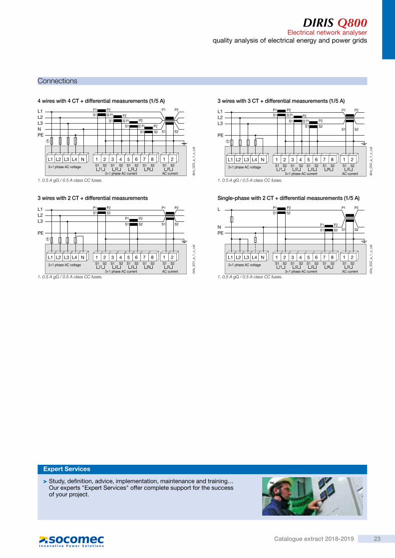
Connections
4 wires with 4 CT + differential measurements (1/5 A)
1. 0.5 A gG / 0.5 A class CC fuses. 1. 0.5 A gG / 0.5 A class CC fuses.
1. 0.5 A gG / 0.5 A class CC fuses.1. 0.5 A gG / 0.5 A class CC fuses.
3 wires with 3 CT + differential measurements (1/5 A)
3 wires with 2 CT + differential measurements Single-phase with 2 CT + differential measurements (1/5 A)
P2
P2S1
S1 S2 S1 S2
P1 P2
P2S1
P1 P2S1 S2 P1
S2 P1
3+1 phase AC voltage
3+1 phase AC current AC current
L1 L2 L3 L4 N
1
L1L2L3NPE
S2
1 2 3S1 S1
I3 INI2I1S1S2 S2 S1 S2
I5S1 S2
4 5 6 7 8 21
S2 P1P2
S1 S2S1 S2
P1 P2
P2S1 S2 P1
P1 P2S1 S2 P1
3+1 phase AC voltage
3+1 phase AC current AC current
L1 L2 L3 L4 N
1
L1L2L3
PE
S2
1 2 3S1 S1
I3 INI2I1S1S2 S2 S1 S2
I5S1 S2
4 5 6 7 8 21
P2P1
S1 S2
P1 P2S1 S2
3+1 phase AC voltage
3+1 phase AC current AC current
L1 L2 L3 L4 N
1
L1L2L3
PE
S2
1 2 3S1 S1
I3 INI2I1S1S2 S2 S1 S2
I5S1 S2
4 5 6 7 8 21
S1 S2
P1 P2
P1S1 S2
P2S1 S2
P1 P2P1 P2S1 S2
3+1 phase AC voltage
3+1 phase AC current AC current
L1 L2 L3 L4 N
L
NPE
S2
1 2 3S1 S1
I3 INI2I1S1S2 S2 S1 S2
I5S1 S2
4 5 6 7 8 21
diris
_929
_a_1
_x_c
at
diris
_930
_a_1
_x_c
atdi
ris_9
32_a
_1_x
_cat
diris
_931
_a_1
_x_c
at
> Study, definition, advice, implementation, maintenance and training… Our experts "Expert Services" offer complete support for the success of your project.
Expert Services
22 Catalogue extract 2018-2019
DIRIS Q800Electrical network analyserquality analysis of electrical energy and power grids
Terminals
1
2
7
6
5
4
8
WIFI ant.GPS ant. (3.3 VDC out)
3+1 Phase AC Voltage - max. 3x580/1000 V CAT III
DIG. OUT - 24 VDC/max 50 mA1 2 3 4 5 6 7 8 1 2 3 4 5 6 7 8 1 2 3 4 5 6 7 8
DIG. IN - 24 VDC AN. OUT - 4-20 mA/max 500 ohm
3+1 Phase AC Current1(7) A RMS
CH5 (EL) AC Current1(7) A RMS
L1
L1 L2 L3 L4 L5
L2 L3 L4 N
RS485 100-240 VAC 50-60 Hz 15 W 65-250 VDC AUX
C B- A+1 2 3
L N
T500 mAH 250 V
1 2
ON
BATT
ETHERNET10/100 Base T
OFF
9
3
1. Product label2. Earth connection3. RS485 MODBUS RTU communication4. Auxiliary power supply and fuse5. Voltage and current inputs6. Auto MDIX ETHERNET port7. Battery switch8. GPS and WIFI antenna9. Logical outputs, analogue inputs/outputs
1-2: optocoupler output 13-4: optocoupler output 25-6: optocoupler output 37-8: optocoupler output 4
L1, L2, L3, L4, N: voltage inputs
1-2: optocoupler input 13-4: optocoupler input 25-6: optocoupler input 37-8: optocoupler input 4
1-2: current input i13-4: current input i25-6: current input i37-8: current input iN
1-2: differential core connections
1-2: analogue output 13-4: analogue output 25-6: analogue output 37-8: analogue output 4
Communication via RS485 link
Digital outputs
Current and voltage inputs
Ethernet communication
Digital inputs Analogue outputs
AC and DC auxiliary power supply
diris
_933
_a_1
_x_c
at
RS485
C B- A+
LIYCY-CY
diris
_920
_a_1
_x_c
at.e
ps
AUX
85/265 VAC65/250 VDC
PE
L NPE
diris
_921
_a_1
_x_c
at.e
ps
DIRIS Q800
71 4 5 6
DIG. OUT 24 VDC / max 50 mA
2 3 8
diris
_922
_a_1
_x_c
at.e
ps
DIRIS Q800
71 4 5 6
DIG. IN 24 VDC
2 3 8
diris
_923
_a_1
_x_c
at.e
ps
DIRIS Q800
Ethernet 10/100 Base T
diris
_928
_a_1
_x_c
at.e
ps
DIRIS Q800
71 4 5 6
AN. OUT 4-20 mA / max 500 Ohm
2 3 8
diris
_924
_a_1
_x_c
at.e
ps
DIRIS Q800
1
Ch5 (EL) AC current
2
I5
diris
_927
_a_1
_x_c
at.e
ps
DIRIS Q800
71 5
3+1 phase AC current
3 82 4 6
I1 I2 I3 IN
diris
_926
_a_1
_x_c
at.e
ps
DIRIS Q800
L4L1 L3
3+1 phase AC voltage
L2 N
diris
_925
_a_1
_x_c
at.e
ps
DIRIS Q800Electrical network analyser
quality analysis of electrical energy and power grids
Connections
4 wires with 4 CT + differential measurements (1/5 A)
1. 0.5 A gG / 0.5 A class CC fuses. 1. 0.5 A gG / 0.5 A class CC fuses.
1. 0.5 A gG / 0.5 A class CC fuses.1. 0.5 A gG / 0.5 A class CC fuses.
3 wires with 3 CT + differential measurements (1/5 A)
3 wires with 2 CT + differential measurements Single-phase with 2 CT + differential measurements (1/5 A)
P2
P2S1
S1 S2 S1 S2
P1 P2
P2S1
P1 P2S1 S2 P1
S2 P1
3+1 phase AC voltage
3+1 phase AC current AC current
L1 L2 L3 L4 N
1
L1L2L3NPE
S2
1 2 3S1 S1
I3 INI2I1S1S2 S2 S1 S2
I5S1 S2
4 5 6 7 8 21
S2 P1P2
S1 S2S1 S2
P1 P2
P2S1 S2 P1
P1 P2S1 S2 P1
3+1 phase AC voltage
3+1 phase AC current AC current
L1 L2 L3 L4 N
1
L1L2L3
PE
S2
1 2 3S1 S1
I3 INI2I1S1S2 S2 S1 S2
I5S1 S2
4 5 6 7 8 21
P2P1
S1 S2
P1 P2S1 S2
3+1 phase AC voltage
3+1 phase AC current AC current
L1 L2 L3 L4 N
1
L1L2L3
PE
S2
1 2 3S1 S1
I3 INI2I1S1S2 S2 S1 S2
I5S1 S2
4 5 6 7 8 21
S1 S2
P1 P2
P1S1 S2
P2S1 S2
P1 P2P1 P2S1 S2
3+1 phase AC voltage
3+1 phase AC current AC current
L1 L2 L3 L4 N
L
NPE
S2
1 2 3S1 S1
I3 INI2I1S1S2 S2 S1 S2
I5S1 S2
4 5 6 7 8 21
diris
_929
_a_1
_x_c
at
diris
_930
_a_1
_x_c
atdi
ris_9
32_a
_1_x
_cat
diris
_931
_a_1
_x_c
at
> Study, definition, advice, implementation, maintenance and training… Our experts "Expert Services" offer complete support for the success of your project.
Expert Services
23Catalogue extract 2018-2019

Mul
ti-ci
rcui
t m
eter
ing
&
mea
sure
men
tDIRIS Digiware D and CControl and power supply interfaces
Function
DIRIS Digiware D-40, D-50 and D-70DIRIS Digiware D remote displays allow:
- a local view of the data from DIRIS Digiware U, I and IO modules
- a power supply to the DIRIS Digiware modules,
- access to this data over Ethernet (D-50/D-70) or RS485 (D-40).
DIRIS Digiware D-50 and D-70 displays also act as a gateway, centralising measurements from DIRIS Digiware, DIRIS A, DIRIS B and COUNTIS E devices and making them available over Ethernet.With the DIRIS Digiware D-70 display, data can be visualized on Webview, the "Power & Energy monitoring" embedded web server.DIRIS Digiware screens are 24 VDC powered.
DIRIS Digiware C-31For applications without a local displayDIRIS Digiware C-31 interfaces centralise all the system data.An RS485 Modbus output allows them to provide all this information to energy efficiency software (DIRIS G communication gateways are available for communication via Ethernet - Modbus TCP).DIRIS Digiware C-31 interfaces and C-32 repeaters are 24 VDC powered.
> Centralising and displaying measurement data
> A single power supply for the entire system
> A single RS485 or Ethernet output for the entire system
> Webview embedded web server
Strong points
Advantages
DIRIS Digiware D • High-resolution graphic screen • Embedded web server (DIRIS Digiware D-70) • Multi-protocols (Modbus, BACnet, SNMP) • 24 VDC SELV (Safety Extra Low Voltage) power supply elimination of hazardous voltage on cabinet doors.
• Ergonomic and easy to use with 10 direct access buttons for:- measurement information,- output selection,- equipment configuration.
• Centralising measurement points:- circuit selection,- displaying data.
DIRIS Digiware C-31Compact: Centralise your measurement data on 1 module without a local screen, for a complete system:- single 24 V power supply (no dangerous
voltage on DIRIS Digiware modules for a connection with no interruption),
- a single RS485 communication.
> Industry > Building > Infrastructure > Data centers
The solution for
diris
-dw
_006
_a_c
at
diris
-dw
_142
_a
DIRIS Digiware D-40/D-50/D-70Centralisation and display of data
DIRIS Digiware C-31Centralisation
> IEC 61557-12
> ISO 14025
> UL
Compliance with standards
Configuration with EasyConfig,
> Find the best DIRIS Digiware configuration:www.meter-selector.com
Create your project
DIRIS Digiware D and CControl and power supply interfaces
Application Control and power supply interface
DIRIS Digiware C-31 D-40 D-50 D-70
Digiware input • • • •
RS485 input • •
RS485 Modbus output • •
Ethernet output ModbusModbus
BACnet IPSNMP
Webview web server •
WebviewEmbedded web server in the DIRIS Digiware D-70 display
Webview allows the display and remote monitoring of all the electric parameters measured by up to 32 devices. They are displayed in the form of overview screens, graphs or tables for clear and user-friendly analysis.
Access to Webview is made by a web browser on a PC or tablet and offers multiple features such as the automatic export of data by FTP or e-mail notification in the presence of alarms (SMTP).
The Photoview application is available via the Webview interface embedded in the DIRIS Digiware D-70 display. It allows the display of electrical quantities on a customised background picture such as a cabinet, a wiring diagram or the map of a site.
Functions
24 Catalogue extract 2018-2019

Mul
ti-ci
rcui
t m
eter
ing
&
mea
sure
men
t
DIRIS Digiware D and CControl and power supply interfaces
Function
DIRIS Digiware D-40, D-50 and D-70DIRIS Digiware D remote displays allow:
- a local view of the data from DIRIS Digiware U, I and IO modules
- a power supply to the DIRIS Digiware modules,
- access to this data over Ethernet (D-50/D-70) or RS485 (D-40).
DIRIS Digiware D-50 and D-70 displays also act as a gateway, centralising measurements from DIRIS Digiware, DIRIS A, DIRIS B and COUNTIS E devices and making them available over Ethernet.With the DIRIS Digiware D-70 display, data can be visualized on Webview, the "Power & Energy monitoring" embedded web server.DIRIS Digiware screens are 24 VDC powered.
DIRIS Digiware C-31For applications without a local displayDIRIS Digiware C-31 interfaces centralise all the system data.An RS485 Modbus output allows them to provide all this information to energy efficiency software (DIRIS G communication gateways are available for communication via Ethernet - Modbus TCP).DIRIS Digiware C-31 interfaces and C-32 repeaters are 24 VDC powered.
> Centralising and displaying measurement data
> A single power supply for the entire system
> A single RS485 or Ethernet output for the entire system
> Webview embedded web server
Strong points
Advantages
DIRIS Digiware D • High-resolution graphic screen • Embedded web server (DIRIS Digiware D-70) • Multi-protocols (Modbus, BACnet, SNMP) • 24 VDC SELV (Safety Extra Low Voltage) power supply elimination of hazardous voltage on cabinet doors.
• Ergonomic and easy to use with 10 direct access buttons for:- measurement information,- output selection,- equipment configuration.
• Centralising measurement points:- circuit selection,- displaying data.
DIRIS Digiware C-31Compact: Centralise your measurement data on 1 module without a local screen, for a complete system:- single 24 V power supply (no dangerous
voltage on DIRIS Digiware modules for a connection with no interruption),
- a single RS485 communication.
> Industry > Building > Infrastructure > Data centers
The solution for
diris
-dw
_006
_a_c
at
diris
-dw
_142
_a
DIRIS Digiware D-40/D-50/D-70Centralisation and display of data
DIRIS Digiware C-31Centralisation
> IEC 61557-12
> ISO 14025
> UL
Compliance with standards
Configuration with EasyConfig,
> Find the best DIRIS Digiware configuration:www.meter-selector.com
Create your project
DIRIS Digiware D and CControl and power supply interfaces
Application Control and power supply interface
DIRIS Digiware C-31 D-40 D-50 D-70
Digiware input • • • •
RS485 input • •
RS485 Modbus output • •
Ethernet output ModbusModbus
BACnet IPSNMP
Webview web server •
WebviewEmbedded web server in the DIRIS Digiware D-70 display
Webview allows the display and remote monitoring of all the electric parameters measured by up to 32 devices. They are displayed in the form of overview screens, graphs or tables for clear and user-friendly analysis.
Access to Webview is made by a web browser on a PC or tablet and offers multiple features such as the automatic export of data by FTP or e-mail notification in the presence of alarms (SMTP).
The Photoview application is available via the Webview interface embedded in the DIRIS Digiware D-70 display. It allows the display of electrical quantities on a customised background picture such as a cabinet, a wiring diagram or the map of a site.
Functions
25Catalogue extract 2018-2019

DIRIS Digiware D and CControl and power supply interfaces
Dimensions
DIRIS Digiware D-40/D-50/D-70 DIRIS Digiware C-31
C-3x
90
18 6544 15di
ris-d
w_0
62_a
_1_x
_cat
diris
-dw
_037
_b_1
_x_c
at
92 1827
92
Configuration
The total power consumed by the equipment connected to the Digiware Bus must not exceed the power from the 24 VDC supply.The power supply must not exceed 20 W/70°C or 27 W/40°C.Size with P15 power supply (ref: 4829 0120) delivering 15 WFor example, it is possible to use • 1 DIRIS Digiware D-50 display (2W) • 1 DIRIS Digiware voltage module U-xx (0.72 W) • 50 metres of cable (1.5 W)
and • 20 DIRIS Digiware current modules I-3x (20 x 0.52 = 10.4 W) Total power = 14.62 W
or • 9 DIRIS Digiware current modules I-4x (9 x 1.125 = 10.125 W) Total power = 14.345 W.
Size with a 24 VDC power supply delivering a maximum of 20 WFor example, it is possible to use • 1 DIRIS Digiware D-50 display (2W) • 1 DIRIS Digiware voltage module U-xx (0.72 W) • 50 metres of cable (1.5 W)
and • 30 DIRIS Digiware current modules I-3x (30 x 0.52 = 15.6 W) Total power = 19.82 W
or • 14 DIRIS Digiware current modules I-4x (14 x 1.125 = 15.72) Total power = 19.97 W.
Product Power delivered (W) Power consumed (W)
Power supplyP15 100-240 VAC / 24 VDC 15
Cables50 metre package 1.5
System interfacesDIRIS Digiware D-40/D-50 2
DIRIS Digiware D-70 2.5
DIRIS Digiware C-31 0.8
Module voltageDIRIS Digiware U-xx 0.72
Current modulesDIRIS Digiware I-3x 0.52
DIRIS Digiware I-4x 1.125
DIRIS Digiware I-6x 0.7
Input/output modulesDIRIS Digiware IO-10/IO-20 0.5
RepeaterDIRIS Digiware C-32 1.5
Equipment consumption Calculation rules for the max. number of products on the Digiware Bus
diris
-dw
_039
_b_1
_en_
cat
RepeaterWhenever the power consumption is higher than 20 W or the distance is greater than 100 m, a DIRIS Digiware C-32 repeater is required.In a DIRIS Digiware system, a maximum of 2 repeaters may be used.
100 m maxor max. 20 W power consumption
100 m maxor max. 20 W power consumption
U-xx I-3x I-3xC-32
I-4x I-4x24 VDC power supply
24 VDC power supply
DIRIS Digiware D-x0
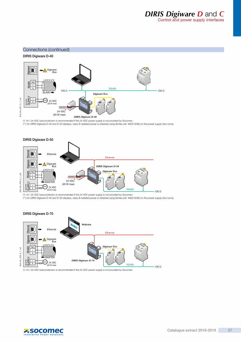
DIRIS Digiware D and CControl and power supply interfaces
Connections (continued)
*
RS485 120 Ω120 Ω
DIRIS Digiware D-40
Digiware Bus
24 VDC(20 W max)
NC
RS48
5Di
giw
are
LIYCY-CY
SLAVE
24 V
SUPP
LY
24 VDC(20 W max)
DigiwareBus
*24 VDC(20 W max)
RS485
DIRIS Digiware D-50
Digiware Bus
Ethernet
120 Ω
NC
RS48
5Di
giw
are
LIYCY-CY
Ethernet
DigiwareBus
MASTER
24 VDC(20 W max)
Ethe
rnet
24 V
SUPP
LY
RS485
DIRIS Digiware D-70
Webview
Digiware Bus
Ethernet
120 Ω
NC
RS48
5Di
giw
are
LIYCY-CY
Ethernet
DigiwareBus
MASTER
24 VDC(20 W max)
Ethe
rnet
24 V
SUPP
LY
DIRIS Digiware D-40
DIRIS Digiware D-50
DIRIS Digiware D-70
diris
-dw
_057
_b_1
_cat
diris
-dw
_056
_b_1
_cat
diris
-dw
_056
_a_1
_cat
(*) 1A / 24 VDC fuse protection is recommended if the 24 VDC power supply is not provided by Socomec.(**) On DIRIS Digiware D-40 and D-50 displays, class B radiated power is obtained using ferrites (ref. 4829 0048) on the power supply (two turns).
(*) 1A / 24 VDC fuse protection is recommended if the 24 VDC power supply is not provided by Socomec.(**) On DIRIS Digiware D-40 and D-50 displays, class B radiated power is obtained using ferrites (ref. 4829 0048) on the power supply (two turns).
(*) 1A / 24 VDC fuse protection is recommended if the 24 VDC power supply is not provided by Socomec.
26 Catalogue extract 2018-2019
DIRIS Digiware D and CControl and power supply interfaces
Dimensions
DIRIS Digiware D-40/D-50/D-70 DIRIS Digiware C-31
C-3x
90
18 6544 15di
ris-d
w_0
62_a
_1_x
_cat
diris
-dw
_037
_b_1
_x_c
at
92 1827
92
Configuration
The total power consumed by the equipment connected to the Digiware Bus must not exceed the power from the 24 VDC supply.The power supply must not exceed 20 W/70°C or 27 W/40°C.Size with P15 power supply (ref: 4829 0120) delivering 15 WFor example, it is possible to use • 1 DIRIS Digiware D-50 display (2W) • 1 DIRIS Digiware voltage module U-xx (0.72 W) • 50 metres of cable (1.5 W)
and • 20 DIRIS Digiware current modules I-3x (20 x 0.52 = 10.4 W) Total power = 14.62 W
or • 9 DIRIS Digiware current modules I-4x (9 x 1.125 = 10.125 W) Total power = 14.345 W.
Size with a 24 VDC power supply delivering a maximum of 20 WFor example, it is possible to use • 1 DIRIS Digiware D-50 display (2W) • 1 DIRIS Digiware voltage module U-xx (0.72 W) • 50 metres of cable (1.5 W)
and • 30 DIRIS Digiware current modules I-3x (30 x 0.52 = 15.6 W) Total power = 19.82 W
or • 14 DIRIS Digiware current modules I-4x (14 x 1.125 = 15.72) Total power = 19.97 W.
Product Power delivered (W) Power consumed (W)
Power supplyP15 100-240 VAC / 24 VDC 15
Cables50 metre package 1.5
System interfacesDIRIS Digiware D-40/D-50 2
DIRIS Digiware D-70 2.5
DIRIS Digiware C-31 0.8
Module voltageDIRIS Digiware U-xx 0.72
Current modulesDIRIS Digiware I-3x 0.52
DIRIS Digiware I-4x 1.125
DIRIS Digiware I-6x 0.7
Input/output modulesDIRIS Digiware IO-10/IO-20 0.5
RepeaterDIRIS Digiware C-32 1.5
Equipment consumption Calculation rules for the max. number of products on the Digiware Bus
diris
-dw
_039
_b_1
_en_
cat
RepeaterWhenever the power consumption is higher than 20 W or the distance is greater than 100 m, a DIRIS Digiware C-32 repeater is required.In a DIRIS Digiware system, a maximum of 2 repeaters may be used.
100 m maxor max. 20 W power consumption
100 m maxor max. 20 W power consumption
U-xx I-3x I-3xC-32
I-4x I-4x24 VDC power supply
24 VDC power supply
DIRIS Digiware D-x0
DIRIS Digiware D and CControl and power supply interfaces
Connections (continued)
*
RS485 120 Ω120 Ω
DIRIS Digiware D-40
Digiware Bus
24 VDC(20 W max)
NC
RS48
5Di
giw
are
LIYCY-CY
SLAVE
24 V
SUPP
LY
24 VDC(20 W max)
DigiwareBus
*24 VDC(20 W max)
RS485
DIRIS Digiware D-50
Digiware Bus
Ethernet
120 Ω
NC
RS48
5Di
giw
are
LIYCY-CY
Ethernet
DigiwareBus
MASTER
24 VDC(20 W max)
Ethe
rnet
24 V
SUPP
LY
RS485
DIRIS Digiware D-70
Webview
Digiware Bus
Ethernet
120 Ω
NC
RS48
5Di
giw
are
LIYCY-CY
Ethernet
DigiwareBus
MASTER
24 VDC(20 W max)
Ethe
rnet
24 V
SUPP
LY
DIRIS Digiware D-40
DIRIS Digiware D-50
DIRIS Digiware D-70
diris
-dw
_057
_b_1
_cat
diris
-dw
_056
_b_1
_cat
diris
-dw
_056
_a_1
_cat
(*) 1A / 24 VDC fuse protection is recommended if the 24 VDC power supply is not provided by Socomec.(**) On DIRIS Digiware D-40 and D-50 displays, class B radiated power is obtained using ferrites (ref. 4829 0048) on the power supply (two turns).
(*) 1A / 24 VDC fuse protection is recommended if the 24 VDC power supply is not provided by Socomec.(**) On DIRIS Digiware D-40 and D-50 displays, class B radiated power is obtained using ferrites (ref. 4829 0048) on the power supply (two turns).
(*) 1A / 24 VDC fuse protection is recommended if the 24 VDC power supply is not provided by Socomec.
27Catalogue extract 2018-2019

DIRIS Digiware D and CControl and power supply interfaces
References
DIRIS Digiware Part number
D-40 Multipoint display, RS485 output 4829 0199D-50 Multipoint display, Ethernet output 4829 0201D-70 Multipoint display, Ethernet output + web server 4829 0202C-31 System interface 4829 0101C-32 Repeater 4829 0103
Power supply Part number
P15 Powers supply 100-240 VAC/ 24 VDC 15 W 4829 0120Digiware connection cables Part number
RJ45 cables for Digiware Bus
Length 0.10m 4829 0181Length 0.20 m 4829 0188Length 0.50 m 4829 0182Length 1 m 4829 0183Length 2 m 4829 0184Length 5 m 4829 0186Length 10 m 4829 018750 m reel + 100 connectors 4829 0185
Termination for Digiware Bus (supplied with interfaces C and D) 4829 0180USB configuration cable 4829 0050
Single-point display Part number
DIRIS D-30(1) Single-point display for DIRIS Digiware I-4x 4829 0200(1) DIRIS D-30 display characteristics
Accessories
Accessories To be orderedin multiples of Part number
Fuse circuit breakers to protect voltage inputs (type RM) 1 pole + neutral 4 5601 0017
gG 10x38 0.5 A fuses 10 6012 0000
Expert Services
Require integration onto your network?No problem for our "Expert Services" team. They will fully integrate all your SOCOMEC devices, audit your system, commission selected equipment and train your staff on its use.For further information, please contact your nearest SOCOMEC branch.
DIRIS Digiware D and CControl and power supply interfaces
Technical characteristics
Environmental specificationsAmbient operating temperature -10 to +70°C
Storage temperature -25 to +70°C
Operating humidity 55 °C / 97% HR
Operating altitude < 2000 m
Mechanical featuresCasing type DIN-rail mounting module and base
Casing protection index IP20 / IK06
Front panel protection index IP40 on the nose in modular assembly / IK06
Electrical characteristicsDIRIS Digiware C-31
Input voltage 24 VDC ± 20 % - 20 W max
Connection Removable screw terminal block, 2 positions,stranded or solid 0.2-2.5 mm² cable
P15 power supply Characteristics: 100-240 VAC/ 24 VDC - 0,63 A - 15 WModular format - Dimensions (H x L): 90 x 25 mm
Communication specificationsDigiware Bus
Function Connection between DIRIS Digiware modules
Cable type Specific Socomec cable with RJ45 connections
RS485
Connection type 2 to 3 half duplex wires
Protocol Modbus RTU
Baudrate 1200 to 115 200 bauds
Function Data configuration and reading
Location Single-point on DIRIS Digiware C
Ports D-40 D-50/D-70
Inputs Digiware Digiware RS485
Outputs RS485 Ethernet
DIRIS Digiware D-40/D-50/D-70 featuresMechanical characteristics
Type of screen Capacitive touch-screen technology, 10 keys
Screen resolution 350 x 160 pixels
Front panel protection index IP65
Communication
Ethernet RJ45 10/100 Mbs
Gateway function:Modbus TCP (D-50/D-70)BACnet IP (D-70)SNMP v1, v2, v3 (D-70)
RJ45 Digiware Control and power supply interface function
RS485 2-3 wires Modbus RTU communication function(input D-50/D-70/output D-40)
USB Upgrade and configuration via type B micro USB connector
Electrical characteristics
Power supply 24 VDC +10 % / -20%
Power consumption 2 VA (D-40/D-50) / 2.5 VA (D-70)
Environmental specifications
Storage temperature -20 to +70°C
Operating temperature -10 to +55°C
Humidity 95% at 40°C
Installation category, degree of pollution CAT III, 2
NCR
S48
5 LIYCY-CYS
uppl
y24
VD
C1
2O
N
Communication
diris
-dw
_018
_b_1
_x_c
at
diris
-dw
_057
_a_1
_en_
cat
24 V
SUPP
LYR
S48
5NC
DIG
IWA
RE
BU
S
RJ4
5
Digiware busPower supply
DIRIS Digiware C-31
diris
-dw
_012
_a_1
_x_c
at
diris
-dw
_023
_b_1
_x_c
at
DIG
IWA
RE
BU
S
RJ4
5 INO
UT
24 V
SUPP
LY
Digiware busPower supply
DIRIS Digiware C-32
diris
-dw
_024
_b_1
_x_c
at
diris
-dw
_013
_a_1
_x_c
at
7 mm
24VDCSupply
7 mm
ComRS485 ModbusComRS485 Modbus
DIRIS Digiware C-31
Connections
28 Catalogue extract 2018-2019

DIRIS Digiware D and CControl and power supply interfaces
References
DIRIS Digiware Part number
D-40 Multipoint display, RS485 output 4829 0199D-50 Multipoint display, Ethernet output 4829 0201D-70 Multipoint display, Ethernet output + web server 4829 0202C-31 System interface 4829 0101C-32 Repeater 4829 0103
Power supply Part number
P15 Powers supply 100-240 VAC/ 24 VDC 15 W 4829 0120Digiware connection cables Part number
RJ45 cables for Digiware Bus
Length 0.10m 4829 0181Length 0.20 m 4829 0188Length 0.50 m 4829 0182Length 1 m 4829 0183Length 2 m 4829 0184Length 5 m 4829 0186Length 10 m 4829 018750 m reel + 100 connectors 4829 0185
Termination for Digiware Bus (supplied with interfaces C and D) 4829 0180USB configuration cable 4829 0050
Single-point display Part number
DIRIS D-30(1) Single-point display for DIRIS Digiware I-4x 4829 0200(1) DIRIS D-30 display characteristics
Accessories
Accessories To be orderedin multiples of Part number
Fuse circuit breakers to protect voltage inputs (type RM) 1 pole + neutral 4 5601 0017
gG 10x38 0.5 A fuses 10 6012 0000
Expert Services
Require integration onto your network?No problem for our "Expert Services" team. They will fully integrate all your SOCOMEC devices, audit your system, commission selected equipment and train your staff on its use.For further information, please contact your nearest SOCOMEC branch.
DIRIS Digiware D and CControl and power supply interfaces
Technical characteristics
Environmental specificationsAmbient operating temperature -10 to +70°C
Storage temperature -25 to +70°C
Operating humidity 55 °C / 97% HR
Operating altitude < 2000 m
Mechanical featuresCasing type DIN-rail mounting module and base
Casing protection index IP20 / IK06
Front panel protection index IP40 on the nose in modular assembly / IK06
Electrical characteristicsDIRIS Digiware C-31
Input voltage 24 VDC ± 20 % - 20 W max
Connection Removable screw terminal block, 2 positions,stranded or solid 0.2-2.5 mm² cable
P15 power supply Characteristics: 100-240 VAC/ 24 VDC - 0,63 A - 15 WModular format - Dimensions (H x L): 90 x 25 mm
Communication specificationsDigiware Bus
Function Connection between DIRIS Digiware modules
Cable type Specific Socomec cable with RJ45 connections
RS485
Connection type 2 to 3 half duplex wires
Protocol Modbus RTU
Baudrate 1200 to 115 200 bauds
Function Data configuration and reading
Location Single-point on DIRIS Digiware C
Ports D-40 D-50/D-70
Inputs Digiware Digiware RS485
Outputs RS485 Ethernet
DIRIS Digiware D-40/D-50/D-70 featuresMechanical characteristics
Type of screen Capacitive touch-screen technology, 10 keys
Screen resolution 350 x 160 pixels
Front panel protection index IP65
Communication
Ethernet RJ45 10/100 Mbs
Gateway function:Modbus TCP (D-50/D-70)BACnet IP (D-70)SNMP v1, v2, v3 (D-70)
RJ45 Digiware Control and power supply interface function
RS485 2-3 wires Modbus RTU communication function(input D-50/D-70/output D-40)
USB Upgrade and configuration via type B micro USB connector
Electrical characteristics
Power supply 24 VDC +10 % / -20%
Power consumption 2 VA (D-40/D-50) / 2.5 VA (D-70)
Environmental specifications
Storage temperature -20 to +70°C
Operating temperature -10 to +55°C
Humidity 95% at 40°C
Installation category, degree of pollution CAT III, 2
NC
RS
485 LIYCY-CY
Sup
ply
24V
DC
12
ON
Communication
diris
-dw
_018
_b_1
_x_c
at
diris
-dw
_057
_a_1
_en_
cat
24 V
SUPP
LYR
S48
5NC
DIG
IWA
RE
BU
S
RJ4
5
Digiware busPower supply
DIRIS Digiware C-31
diris
-dw
_012
_a_1
_x_c
at
diris
-dw
_023
_b_1
_x_c
at
DIG
IWA
RE
BU
S
RJ4
5 INO
UT
24 V
SUPP
LY
Digiware busPower supply
DIRIS Digiware C-32
diris
-dw
_024
_b_1
_x_c
at
diris
-dw
_013
_a_1
_x_c
at
7 mm
24VDCSupply
7 mm
ComRS485 ModbusComRS485 Modbus
DIRIS Digiware C-31
Connections
29Catalogue extract 2018-2019

Mul
ti-ci
rcui
t m
eter
ing
&
mea
sure
men
t
Function
The DIRIS Digiware U module measures voltage for the entire system. This pools together all voltage measurements.The Digiware RJ45 Bus allows you to pass voltage measurements as well as power supply and communication to all connected products.
> 1 single voltage measurement point for the entire system
> Plug & Play > Compact
Strong points
Advantages
• 1 single voltage measurement point for the entire system.
• Single point of protection for voltage measuring.
• A complete, dedicated solution:- metering,- monitoring voltage,- quality analysis of the supplied voltage.
• No hazardous voltage on cabinet doors. • Adapted to all types of network: single-phase, three-phase.
> Industry > Building > Infrastructure > Data center
The solution for
diris
-dw
_005
_a_c
at
DIRIS Digiware U-10/U-20/ U-30
> IEC 61557-12
> ISO 14025
> UL
Conformity to standards
> Find the best DIRIS Digiware configuration:www.meter-selector.com
Create your project
Configuration with EasyConfig,
DIRIS Digiware UVoltage acquisition module
RJ45 (Digiware Bus) cables are available.
RJ45Communication
DIRIS Digiware UVoltage acquisition module
Dimensions
DIRIS Digiware U
90
18 6544 15 di
ris-d
w_0
59_a
_1_x
_cat
Voltage measurement moduleApplication Metering Monitoring Analysis
DIRIS Digiware U U-10 U-20 U-30
Multi-measurementU12, U23, U31, V1, V2, V3, f • • •
U system, V system •
Ph/N unbalance •
Ph/Ph unbalance •
Quality analysisTHDv1, THDv2, THDv3, THDu12, THDu23, THDu31 • •
Individual harmonics U & V (up to rank 63) •
Voltage dips, cutoffs and surges (EN 50160) •
AlarmsOn threshold •
History of average values45 days (max) •
FormatWidth/number of modules 18 mm / 1 18 mm / 1 18 mm / 1
Specifications
Communication specificationsUSB
Protocol Modbus RTU on USB
Function Configuration of DIRIS Digiware U and I modules
Location On each DIRIS Digiware U and I measurement module
Connection Type B micro USB connector
Measuring characteristicsVoltage measurement - DIRIS Digiware U
Characteristics of the network measured 50-300 VAC (Ph/N) - 87-520 VAC (Ph/Ph) - CAT III
Frequency range 45 … 65 Hz
Frequency accuracy Class 0.02
Network type Single-phase/ Two-phase / Two-phase with neutral / Three-phase / Three-phase with neutral
Measurement by voltage transformer
Primary: 400 000 VACSecondary: 60, 100, 110, 173, 190 VAC
Input consumption ≤ 0.1 VA
Permanent overload 300 VAC Ph/N
Accuracy of voltage measurement Class 0.2
Connection Removable screw terminal block, 4 positions,stranded or solid 0.2 … 2.5 mm² cable
ReferencesDigiware connection cables Reference
RJ45 cables for Digiware Bus
Length 0.10 m 4829 0181Length 0.20 m 4829 0188Length 0.50 m 4829 0182Length 1 m 4829 0183Length 2 m 4829 0184Length 5 m 4829 0186Length 10 m 4829 0187Reel 50 m + 100 connectors 4829 0185
Digiware bus terminating resistor (supplied with C and D devices) 4829 0180USB configuration cable 4829 0050
DIRIS Digiware Reference
U-10 Metering 4829 0105U-20 Monitoring 4829 0106U-30 Analysis 4829 0102
Accessories
Description of accessories To be orderedin multiples of Reference
Fuse holder to protect voltage inputs (type RM) 3 pole 4 5601 0018
gG 10x38 0.5 A fuses 10 6012 0000
30 Catalogue extract 2018-2019
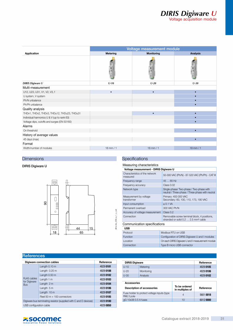
Mul
ti-ci
rcui
t m
eter
ing
&
mea
sure
men
t
Function
The DIRIS Digiware U module measures voltage for the entire system. This pools together all voltage measurements.The Digiware RJ45 Bus allows you to pass voltage measurements as well as power supply and communication to all connected products.
> 1 single voltage measurement point for the entire system
> Plug & Play > Compact
Strong points
Advantages
• 1 single voltage measurement point for the entire system.
• Single point of protection for voltage measuring.
• A complete, dedicated solution:- metering,- monitoring voltage,- quality analysis of the supplied voltage.
• No hazardous voltage on cabinet doors. • Adapted to all types of network: single-phase, three-phase.
> Industry > Building > Infrastructure > Data center
The solution for
diris
-dw
_005
_a_c
at
DIRIS Digiware U-10/U-20/ U-30
> IEC 61557-12
> ISO 14025
> UL
Conformity to standards
> Find the best DIRIS Digiware configuration:www.meter-selector.com
Create your project
Configuration with EasyConfig,
DIRIS Digiware UVoltage acquisition module
RJ45 (Digiware Bus) cables are available.
RJ45
Communication
DIRIS Digiware UVoltage acquisition module
Dimensions
DIRIS Digiware U
90
18 6544 15 di
ris-d
w_0
59_a
_1_x
_cat
Voltage measurement moduleApplication Metering Monitoring Analysis
DIRIS Digiware U U-10 U-20 U-30
Multi-measurementU12, U23, U31, V1, V2, V3, f • • •
U system, V system •
Ph/N unbalance •
Ph/Ph unbalance •
Quality analysisTHDv1, THDv2, THDv3, THDu12, THDu23, THDu31 • •
Individual harmonics U & V (up to rank 63) •
Voltage dips, cutoffs and surges (EN 50160) •
AlarmsOn threshold •
History of average values45 days (max) •
FormatWidth/number of modules 18 mm / 1 18 mm / 1 18 mm / 1
Specifications
Communication specificationsUSB
Protocol Modbus RTU on USB
Function Configuration of DIRIS Digiware U and I modules
Location On each DIRIS Digiware U and I measurement module
Connection Type B micro USB connector
Measuring characteristicsVoltage measurement - DIRIS Digiware U
Characteristics of the network measured 50-300 VAC (Ph/N) - 87-520 VAC (Ph/Ph) - CAT III
Frequency range 45 … 65 Hz
Frequency accuracy Class 0.02
Network type Single-phase/ Two-phase / Two-phase with neutral / Three-phase / Three-phase with neutral
Measurement by voltage transformer
Primary: 400 000 VACSecondary: 60, 100, 110, 173, 190 VAC
Input consumption ≤ 0.1 VA
Permanent overload 300 VAC Ph/N
Accuracy of voltage measurement Class 0.2
Connection Removable screw terminal block, 4 positions,stranded or solid 0.2 … 2.5 mm² cable
ReferencesDigiware connection cables Reference
RJ45 cables for Digiware Bus
Length 0.10 m 4829 0181Length 0.20 m 4829 0188Length 0.50 m 4829 0182Length 1 m 4829 0183Length 2 m 4829 0184Length 5 m 4829 0186Length 10 m 4829 0187Reel 50 m + 100 connectors 4829 0185
Digiware bus terminating resistor (supplied with C and D devices) 4829 0180USB configuration cable 4829 0050
DIRIS Digiware Reference
U-10 Metering 4829 0105U-20 Monitoring 4829 0106U-30 Analysis 4829 0102
Accessories
Description of accessories To be orderedin multiples of Reference
Fuse holder to protect voltage inputs (type RM) 3 pole 4 5601 0018
gG 10x38 0.5 A fuses 10 6012 0000
31Catalogue extract 2018-2019
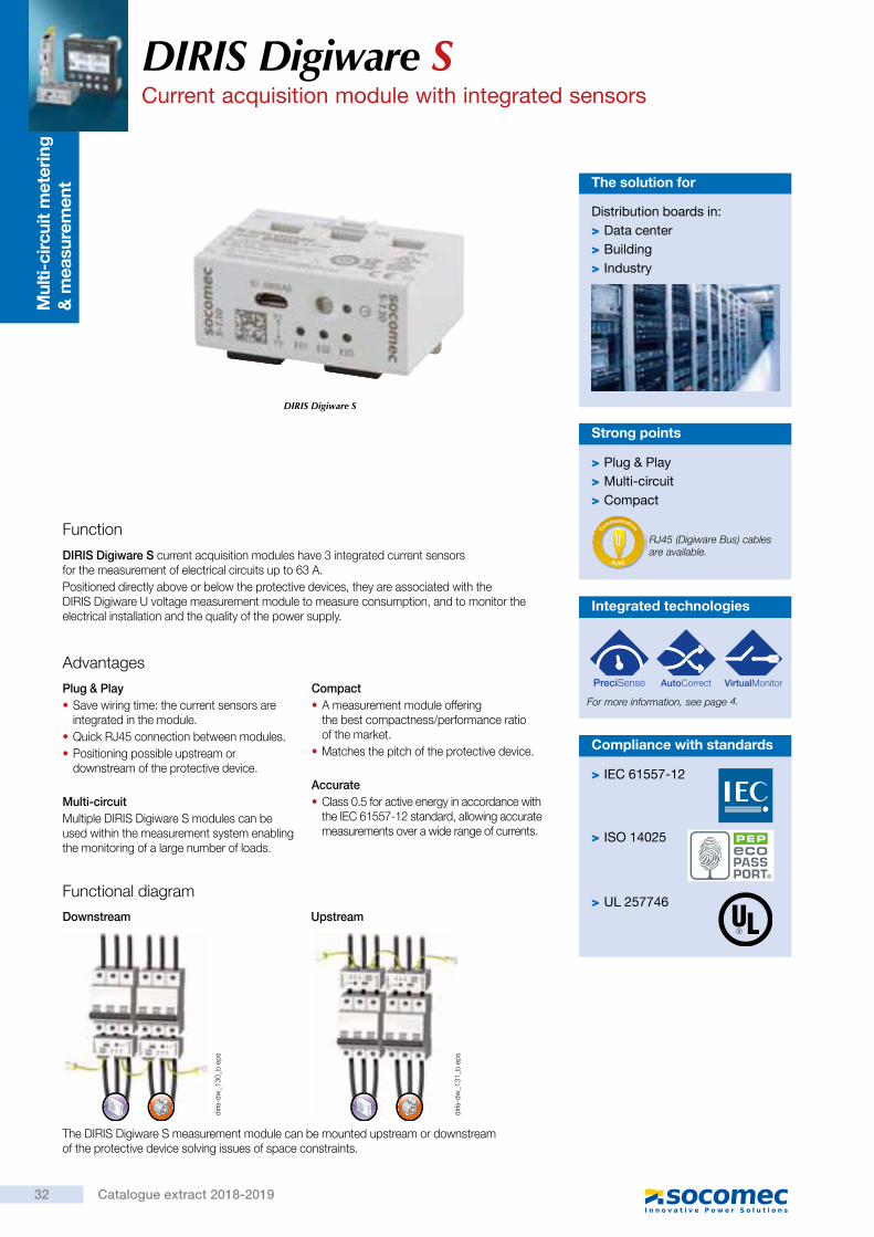
Mul
ti-ci
rcui
t m
eter
ing
&
mea
sure
men
t
Function
DIRIS Digiware S current acquisition modules have 3 integrated current sensors for the measurement of electrical circuits up to 63 A.Positioned directly above or below the protective devices, they are associated with the DIRIS Digiware U voltage measurement module to measure consumption, and to monitor the electrical installation and the quality of the power supply.
Advantages
Plug & Play • Save wiring time: the current sensors are integrated in the module.
• Quick RJ45 connection between modules. • Positioning possible upstream or downstream of the protective device.
Multi-circuitMultiple DIRIS Digiware S modules can be used within the measurement system enabling the monitoring of a large number of loads.
Compact • A measurement module offering the best compactness/performance ratio of the market.
• Matches the pitch of the protective device.
Accurate • Class 0.5 for active energy in accordance with the IEC 61557-12 standard, allowing accurate measurements over a wide range of currents.
Functional diagram
Distribution boards in: > Data center > Building > Industry
The solution for
DIRIS Digiware S
> IEC 61557-12
> ISO 14025
> UL 257746
Compliance with standards
Configuration with EasyConfig,
DIRIS Digiware SCurrent acquisition module with integrated sensors
> Plug & Play > Multi-circuit > Compact
Strong points
RJ45 (Digiware Bus) cables are available.
RJ45
Communication
Downstream Upstream
The DIRIS Digiware S measurement module can be mounted upstream or downstream of the protective device solving issues of space constraints.
Integrated technologies
For more information, see page
diris
-dw
_130
_b.e
ps
diris
-dw
_131
_b.e
ps
DIRIS Digiware SCurrent acquisition module with integrated sensors
Current measurement module with integrated sensorsApplication Metering Analysis Monitoring
DIRIS Digiware S S-130 S-135 S-DatacenterNumber of current inputs 3 3 3Base current Ib 10 A 10 A 10 A
Maximum current Imax 63 A 63 A 63 A
Load type accepted1P + N
2P / 2P + N3P / 3P + N
1P + N2P / 2P + N3P / 3P + N
1P + N
Metering± kWh, ± kvarh, kVAh • • •
Multi-tariff (max 8) •
Load curves • •
Multi-measurement
I1, I2, I3, In, ΣP, ΣQ, ΣS, ΣPF • • •
P, Q, S, PF per phase • •
Predictive power •
Current unbalance (Inba, Inb, Idir, Iinv, Ihom) •
Phi, cos Phi, tan Phi • •
QualityTHDi1, THDi2, THDi3, THDin • •
Individual harmonics I (up to level 63rd) •
Crest factors U, V, I •
K factor •
Overcurrents •
AlarmsThresholds and combinations • •
Load level •
Wiring errors • •
Protective device • •
TrendsAverage values • •
FormatWidth 54 mm 54 mm 54 mm
Mounting accessories
Temporary MCB insert(for use during panel assembly)
DIN rail and back plate mounting Cable tie tether
diris
-dw
_139
_a.e
ps
diris
-dw
_138
_a.e
ps
diris
-dw
_137
_a.e
ps
32 Catalogue extract 2018-2019
4.

Mul
ti-ci
rcui
t m
eter
ing
&
mea
sure
men
t
Function
DIRIS Digiware S current acquisition modules have 3 integrated current sensors for the measurement of electrical circuits up to 63 A.Positioned directly above or below the protective devices, they are associated with the DIRIS Digiware U voltage measurement module to measure consumption, and to monitor the electrical installation and the quality of the power supply.
Advantages
Plug & Play • Save wiring time: the current sensors are integrated in the module.
• Quick RJ45 connection between modules. • Positioning possible upstream or downstream of the protective device.
Multi-circuitMultiple DIRIS Digiware S modules can be used within the measurement system enabling the monitoring of a large number of loads.
Compact • A measurement module offering the best compactness/performance ratio of the market.
• Matches the pitch of the protective device.
Accurate • Class 0.5 for active energy in accordance with the IEC 61557-12 standard, allowing accurate measurements over a wide range of currents.
Functional diagram
Distribution boards in: > Data center > Building > Industry
The solution for
DIRIS Digiware S
> IEC 61557-12
> ISO 14025
> UL 257746
Compliance with standards
Configuration with EasyConfig,
DIRIS Digiware SCurrent acquisition module with integrated sensors
> Plug & Play > Multi-circuit > Compact
Strong points
RJ45 (Digiware Bus) cables are available.
RJ45
Communication
Downstream Upstream
The DIRIS Digiware S measurement module can be mounted upstream or downstream of the protective device solving issues of space constraints.
Integrated technologies
For more information, see page
diris
-dw
_130
_b.e
ps
diris
-dw
_131
_b.e
ps
DIRIS Digiware SCurrent acquisition module with integrated sensors
Current measurement module with integrated sensorsApplication Metering Analysis Monitoring
DIRIS Digiware S S-130 S-135 S-DatacenterNumber of current inputs 3 3 3Base current Ib 10 A 10 A 10 A
Maximum current Imax 63 A 63 A 63 A
Load type accepted1P + N
2P / 2P + N3P / 3P + N
1P + N2P / 2P + N3P / 3P + N
1P + N
Metering± kWh, ± kvarh, kVAh • • •
Multi-tariff (max 8) •
Load curves • •
Multi-measurement
I1, I2, I3, In, ΣP, ΣQ, ΣS, ΣPF • • •
P, Q, S, PF per phase • •
Predictive power •
Current unbalance (Inba, Inb, Idir, Iinv, Ihom) •
Phi, cos Phi, tan Phi • •
QualityTHDi1, THDi2, THDi3, THDin • •
Individual harmonics I (up to level 63rd) •
Crest factors U, V, I •
K factor •
Overcurrents •
AlarmsThresholds and combinations • •
Load level •
Wiring errors • •
Protective device • •
TrendsAverage values • •
FormatWidth 54 mm 54 mm 54 mm
Mounting accessories
Temporary MCB insert(for use during panel assembly)
DIN rail and back plate mounting Cable tie tether
diris
-dw
_139
_a.e
ps
diris
-dw
_138
_a.e
ps
diris
-dw
_137
_a.e
ps
33Catalogue extract 2018-2019

DIRIS Digiware SCurrent acquisition module with integrated sensors
Connections
3 Load Fuses : 0.5 A gG / BS 88 2 A gG / 0.5 A class CCI01 I02 I03
DIRIS Digiware S
Current is measured by the integrated inputs I01, I02 and I03 on the DIRIS Digiware S module.
3P+N - 3CT 2P+N - 2CT & 2P+N - 1CT
3P+N - 1CT (3x)
3P - 3 CT
1P+N - 1 CT (3x) 2P+N - 1CT (3x)
V1 V2 V3 VNV
L1
L2L3N
3
I01 I02 I03I01 I02 I03
V1 V2 V3 VNV
L1
L2N
2 2
I01 I02 I03
V1 V2 V3 VNV
L1
L2
L3
N
111
V1 V2 V3 VNV
L1
L2L3N
3
I01 I02 I03
I01 I02 I03
V1 V2 V3 VNV
L1
N
111
I01 I02 I03
V1 V2 V3 VNV
L1
L2
N
111
diris
-dw
_123
_a_x
_cat
.ai
diris
-dw
_122
_a_x
_cat
.ai
diris
-dw
_121
_a_x
_cat
.ai
diris
-dw
_120
_a_x
_cat
.ai
diris
-dw
_119
_a_x
_cat
.ai
diris
-dw
_118
_a_x
_cat
.ai
Dimensions (mm)
13
11.5 15.5 15.5
8
28
42.5
54
diris
-dw
_117
_a_e
n_ca
t.eps
DIRIS Digiware SCurrent acquisition module with integrated sensors
Technical characteristics
Measurement characteristics
Mechanical characteristics
Measurement of current
Number of current inputs 3
Associated current sensors Integrated in the product
Basic current Ib 10 A
Maximum current Imax 63 A
Current measurement accuracy Class 0.5 IEC 61557-12
Casing type DIN rail or back plate mounting
Casing protection index IP20 / IK08
Weight 63 g
Module power consumption 0.35 VA
Measurement of energy
Accuracy of active energy Class 0.5 IEC 61557-12
Accuracy of reactive energy Class 1 IEC 61557-12
Communication specificationsDigiware BUS
Function Connection between DIRIS Digiware S, U, I modules and system interfaces
Cable type Specific Socomec cable with RJ45 connections
USB
Protocol MODBUS RTU on USB
Function Configuration of DIRIS Digiware modules
Location On each DIRIS Digiware module
Connection Type B micro USB connector
Environmental specificationsAmbient operating temperature -10 … +55°C
Storage temperature -25 … +70°C
Operating humidity 40°C / 95% RH
Operating altitude < 2000 m
References
DIRIS Digiware S Reference
S-130 Metering - 3 integrated current inputs 4829 0160S-135 Analysis - 3 integrated current inputs 4829 0161
S-Datacenter Single-phase monitoring - 3 integrated current inputs 4829 0162
Accessories Reference
DIN rail and back plate mounting clip (x10) 4829 0195Temporary MCB insert (x10) 4829 0196
Expert Services
Require integration onto your network?No problem for our "Expert Services" team. They will fully integrate all your SOCOMEC devices, audit your system, commission selected equipment and train your staff on its use.For further information, please contact your nearest SOCOMEC branch.
Digiware connection cables Part number
RJ45 cables for Digiware Bus
Length 0.06 m(1) 4829 0189Length 0.10 m 4829 0181Length 0.20 m 4829 0188Length 0.50 m 4829 0182Length 1 m 4829 0183Length 2 m 4829 0184Length 5 m 4829 0186Length 10 m 4829 018750 m reel + 100 connectors 4829 0185
Termination for Digiware Bus (supplied with interfaces C and D) 4829 0180USB configuration cable 4829 0050
(1) The RJ45 6 cm cables can be used on 3-pole or 4-pole protective devices.
34 Catalogue extract 2018-2019
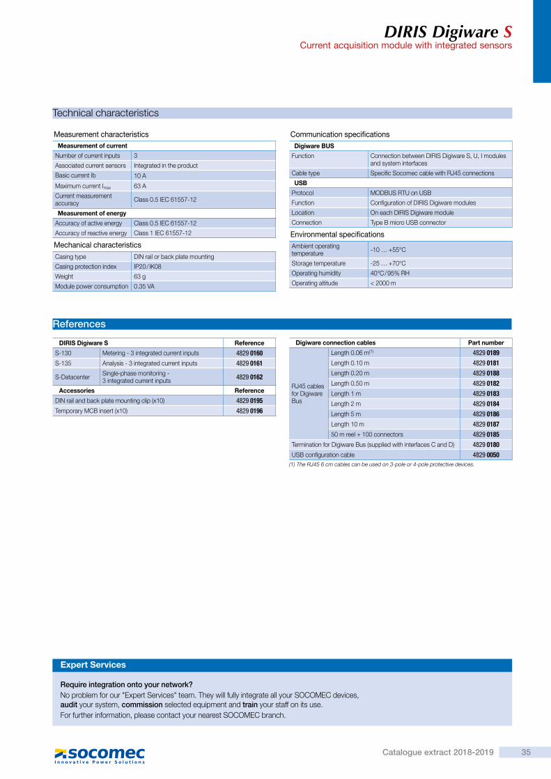
DIRIS Digiware SCurrent acquisition module with integrated sensors
Connections
3 Load Fuses : 0.5 A gG / BS 88 2 A gG / 0.5 A class CCI01 I02 I03
DIRIS Digiware S
Current is measured by the integrated inputs I01, I02 and I03 on the DIRIS Digiware S module.
3P+N - 3CT 2P+N - 2CT & 2P+N - 1CT
3P+N - 1CT (3x)
3P - 3 CT
1P+N - 1 CT (3x) 2P+N - 1CT (3x)
V1 V2 V3 VNV
L1
L2L3N
3
I01 I02 I03I01 I02 I03
V1 V2 V3 VNV
L1
L2N
2 2
I01 I02 I03
V1 V2 V3 VNV
L1
L2
L3
N
111
V1 V2 V3 VNV
L1
L2L3N
3
I01 I02 I03
I01 I02 I03
V1 V2 V3 VNV
L1
N
111
I01 I02 I03
V1 V2 V3 VNV
L1
L2
N
111
diris
-dw
_123
_a_x
_cat
.ai
diris
-dw
_122
_a_x
_cat
.ai
diris
-dw
_121
_a_x
_cat
.ai
diris
-dw
_120
_a_x
_cat
.ai
diris
-dw
_119
_a_x
_cat
.ai
diris
-dw
_118
_a_x
_cat
.ai
Dimensions (mm)
13
11.5 15.5 15.5
8
28
42.5
54
diris
-dw
_117
_a_e
n_ca
t.eps
DIRIS Digiware SCurrent acquisition module with integrated sensors
Technical characteristics
Measurement characteristics
Mechanical characteristics
Measurement of current
Number of current inputs 3
Associated current sensors Integrated in the product
Basic current Ib 10 A
Maximum current Imax 63 A
Current measurement accuracy Class 0.5 IEC 61557-12
Casing type DIN rail or back plate mounting
Casing protection index IP20 / IK08
Weight 63 g
Module power consumption 0.35 VA
Measurement of energy
Accuracy of active energy Class 0.5 IEC 61557-12
Accuracy of reactive energy Class 1 IEC 61557-12
Communication specificationsDigiware BUS
Function Connection between DIRIS Digiware S, U, I modules and system interfaces
Cable type Specific Socomec cable with RJ45 connections
USB
Protocol MODBUS RTU on USB
Function Configuration of DIRIS Digiware modules
Location On each DIRIS Digiware module
Connection Type B micro USB connector
Environmental specificationsAmbient operating temperature -10 … +55°C
Storage temperature -25 … +70°C
Operating humidity 40°C / 95% RH
Operating altitude < 2000 m
References
DIRIS Digiware S Reference
S-130 Metering - 3 integrated current inputs 4829 0160S-135 Analysis - 3 integrated current inputs 4829 0161
S-Datacenter Single-phase monitoring - 3 integrated current inputs 4829 0162
Accessories Reference
DIN rail and back plate mounting clip (x10) 4829 0195Temporary MCB insert (x10) 4829 0196
Expert Services
Require integration onto your network?No problem for our "Expert Services" team. They will fully integrate all your SOCOMEC devices, audit your system, commission selected equipment and train your staff on its use.For further information, please contact your nearest SOCOMEC branch.
Digiware connection cables Part number
RJ45 cables for Digiware Bus
Length 0.06 m(1) 4829 0189Length 0.10 m 4829 0181Length 0.20 m 4829 0188Length 0.50 m 4829 0182Length 1 m 4829 0183Length 2 m 4829 0184Length 5 m 4829 0186Length 10 m 4829 018750 m reel + 100 connectors 4829 0185
Termination for Digiware Bus (supplied with interfaces C and D) 4829 0180USB configuration cable 4829 0050
(1) The RJ45 6 cm cables can be used on 3-pole or 4-pole protective devices.
35Catalogue extract 2018-2019

Mul
ti-ci
rcui
t m
eter
ing
&
mea
sure
men
t
Function
DIRIS Digiware I modules measure consumption and monitor the system at the closest point to the loads. The flexibility of these modules allows you to allocate the loads to be measured or monitored through independent current inputs.For example:- 1 three-phase load,- 3 single-phase loads.
The RJ45 and RJ12 connections allow you to connect modules very quickly and to automatically configure connected current sensors:- communication address,- load type,- sensor type and ratio,- automatic rating and verification of current
travel direction.Wiring errors are also prevented and installation is simplified.
> Multi-circuit > Plug and Play > Compact > High-precision measurement chain
Strong points
Advantages
• RJ45 and RJ12 rapid connection. • Available with 3, 4 or 6 inputs. • Single-output or multi-output for maximum optimisation of the number of products.
• Compact format: 1 or 2 modules sized for integration at the closest point to the loads.
• A complete, dedicated solution:- metering,- monitoring,- quality analysis.
• Compliant with standard IEC 61557-12, guaranteeing the quality and accuracy of the system:- class 0.5 for the 2 - 120% rated current
global measurement chain In (with TE/TF current sensors).
> Industry > Building > Infrastructure > Data center
The solution for
diris
-dw
_004
_a_c
at
diris
-dw
_007
_a_c
at
diris
-dw
_007
_a_c
at
DIRIS Digiware I-3x DIRIS Digiware I-4x DIRIS Digiware I-6x
> IEC 61557-12
> ISO 14025
> UL
Conformity to standards
Configuration with EasyConfig,
DIRIS Digiware I Current acquisition modules
diris
-dw
_007
_a_c
at
diris
-dw
_007
_a_c
at
Integrated technologies
For more information, see page
> Find the best DIRIS Digiware configuration:www.meter-selector.com
Create your project
DIRIS Digiware ICurrent acquisition modules
Current measurement modulesApplication Metering Monitoring Analysis Monitoring Analysis Metering
DIRIS Digiware I I-30 I-31 I-33 I-35 I-43 I-45 I-60 I-61
Number of current inputs3 3 3 3 4 4 6 6
Metering± kWh, ± kvarh, kVAh • • • • • • • •
Load curves • • • •
Multi-tariff • • • •
Multi-measurement
I1, I2, I3, In, ΣP, ΣQ, ΣS, ΣPF • • • • • • • •
P, Q, S, PF per phase • • • •
Predictive power • •
Current unbalance (Inba, Idir, Iinv, Ihom, Inb) • •
Phi, cos Phi, tan Phi • •
QualityTHDi1, THDi2, THDi3, THDin • • • •
Individual harmonics I (up to level 63) • •
Overcurrents • •
AlarmsOn threshold • •
Inputs/outputs 2/2 2/2
History of average values45 days (max) • •
FormatWidth/number of modules 18 mm / 1 18 mm / 1 18 mm / 1 18 mm / 1 27 mm / 1.5 27 mm / 1.5 36 mm / 2 36 mm / 2
Digiware plug-in connectorWith the Digiware plug-in connector you can disconnect a DIRIS Digiware module form the Bus while ensuring the DIRIS Digiware system continues to run downstream. This accessory is particularly useful in applications with retractable drawers or critical applications such as in data centres.
Accessories
I-3x
U-xx
= TEST
ONON
OFF
ON
CLICK
I-3x
I-3x
I-3x
diris
-o_0
25_a
.eps
diris
-o_0
26_a
_1_c
at.a
i
36 Catalogue extract 2018-2019
4.

Mul
ti-ci
rcui
t m
eter
ing
&
mea
sure
men
t
Function
DIRIS Digiware I modules measure consumption and monitor the system at the closest point to the loads. The flexibility of these modules allows you to allocate the loads to be measured or monitored through independent current inputs.For example:- 1 three-phase load,- 3 single-phase loads.
The RJ45 and RJ12 connections allow you to connect modules very quickly and to automatically configure connected current sensors:- communication address,- load type,- sensor type and ratio,- automatic rating and verification of current
travel direction.Wiring errors are also prevented and installation is simplified.
> Multi-circuit > Plug and Play > Compact > High-precision measurement chain
Strong points
Advantages
• RJ45 and RJ12 rapid connection. • Available with 3, 4 or 6 inputs. • Single-output or multi-output for maximum optimisation of the number of products.
• Compact format: 1 or 2 modules sized for integration at the closest point to the loads.
• A complete, dedicated solution:- metering,- monitoring,- quality analysis.
• Compliant with standard IEC 61557-12, guaranteeing the quality and accuracy of the system:- class 0.5 for the 2 - 120% rated current
global measurement chain In (with TE/TF current sensors).
> Industry > Building > Infrastructure > Data center
The solution for
diris
-dw
_004
_a_c
at
diris
-dw
_007
_a_c
at
diris
-dw
_007
_a_c
at
DIRIS Digiware I-3x DIRIS Digiware I-4x DIRIS Digiware I-6x
> IEC 61557-12
> ISO 14025
> UL
Conformity to standards
Configuration with EasyConfig,
DIRIS Digiware I Current acquisition modules
diris
-dw
_007
_a_c
at
diris
-dw
_007
_a_c
at
Integrated technologies
For more information, see page
> Find the best DIRIS Digiware configuration:www.meter-selector.com
Create your project
DIRIS Digiware ICurrent acquisition modules
Current measurement modulesApplication Metering Monitoring Analysis Monitoring Analysis Metering
DIRIS Digiware I I-30 I-31 I-33 I-35 I-43 I-45 I-60 I-61
Number of current inputs3 3 3 3 4 4 6 6
Metering± kWh, ± kvarh, kVAh • • • • • • • •
Load curves • • • •
Multi-tariff • • • •
Multi-measurement
I1, I2, I3, In, ΣP, ΣQ, ΣS, ΣPF • • • • • • • •
P, Q, S, PF per phase • • • •
Predictive power • •
Current unbalance (Inba, Idir, Iinv, Ihom, Inb) • •
Phi, cos Phi, tan Phi • •
QualityTHDi1, THDi2, THDi3, THDin • • • •
Individual harmonics I (up to level 63) • •
Overcurrents • •
AlarmsOn threshold • •
Inputs/outputs 2/2 2/2
History of average values45 days (max) • •
FormatWidth/number of modules 18 mm / 1 18 mm / 1 18 mm / 1 18 mm / 1 27 mm / 1.5 27 mm / 1.5 36 mm / 2 36 mm / 2
Digiware plug-in connectorWith the Digiware plug-in connector you can disconnect a DIRIS Digiware module form the Bus while ensuring the DIRIS Digiware system continues to run downstream. This accessory is particularly useful in applications with retractable drawers or critical applications such as in data centres.
Accessories
I-3x
U-xx
= TEST
ONON
OFF
ON
CLICK
I-3x
I-3x
I-3x
diris
-o_0
25_a
.eps
diris
-o_0
26_a
_1_c
at.a
i
37Catalogue extract 2018-2019

DIRIS Digiware ICurrent acquisition modules
Connections
diris
-dw
_032
_c_1
_x_c
at
Three-phase3P - 3CT (1 three-phase load)
V1 V2 V3 VN
V II01 I02 I03
3
L1
L2
L3
111
diris
-dw
_033
_c_1
_x_c
at
Three-phase3P - 1CT (3 balanced, three-phase loads)
V1 V2 V3 VN
V I
333
I01 I02 I03
L1
L2
L3
111
diris
-b_0
61_a
_1_x
_cat
Single-phase1P+N-1CT (4 single-phase loads)
IV
V1 V2 V3 VN
L1
N
I02 I03I01 I04
1 1 1 1
11
Network and connection examples
1. 0.5 A gG / 0.5 A class CC fuses. 3 Load CT: Current sensor
diris
-dw
_038
_c_1
_x_c
at
Three phase + neutral3P+N - 4CT (1 three-phase load + Neutral measured)
II01 I02 I03 I04
N
V1 V2 V3 VN
V
L1
L2
L3
3 + N
1 1 1
Associated current sensorsVarious types of current sensors are connected to the DIRIS Digiware: closed (TE), split core (TR) or flexible (TF). This range of sensors can be adapted to all types of new or existing installations. A rapid RJ12 connection makes wiring easy and reliable and prevents wiring errors. The DIRIS Digiware system automatically recognises the sensor size and type. This guarantees the overall accuracy of the DIRIS Digiware + current sensor measurement chain.For more information:
I3x
I4x
Dimensions
DIRIS Digiware I-3x / I-6x
I-6xI-3x
90
18 36 6544 15
diris
-dw
_060
_a_1
_x_c
at
DIRIS Digiware I-4x
72
2745
27
21
150
58
45
diris
-dw
_022
_b_1
_x_c
at
DIRIS Digiware ICurrent acquisition modules
Specifications
Measuring characteristicsCurrent measurement - DIRIS Digiware I
Number of current inputs I-3x: 3 / I-45: 4 / I-6x: 6
Associated current sensors Solid TE, split-core TR, flexible TF current sensors
Accuracy of current measurement
0.2 DIRIS Digiware class only Class 0.5 with TE or TF sensors Class 1 with TR sensors
Connection Specific Socomec cable with RJ12 connectors
Inputs - DIRIS Digiware I-45
Number of inputs 2
Type / Power supply Non-insulated input, internal polarisation 12 VDC max, 1mA
Input functions Logic status, pulse meter, multi-tariff
Connection Removable screw terminal block, stranded or solid 0.14-1.5 mm² cable
Outputs - DIRIS Digiware I-45
Number of outputs 2
Relay type 230 VAC ±15 % - 1 A
Function Configurable alarm (current, power, etc.) when threshold is exceeded or remote controlled status
Connection Removable screw terminal block, stranded or solid 0.2-2.5 mm² cable
Communication specificationsUSB
Protocol Modbus RTU on USB
Function Configuration of DIRIS Digiware U and I modules
Location On each DIRIS Digiware U and I measurement module
Connection Type B micro USB connector
References
DIRIS Digiware Reference
I-30 Metering - 3 current inputs 4829 0110I-31 Metering + load curve - 3 current inputs 4829 0111I-33 Monitoring - 3 current inputs 4829 0128I-35 Analysis - 3 current inputs 4829 0130I-43 Monitoring - 2 inputs/ 2 outputs - 4 current inputs 4829 0129I-45 Analysis - 2 inputs/ 2 outputs - 4 current inputs 4829 0131I-60 Metering - 6 current inputs 4829 0112I-61 Metering + load curve - 6 current inputs 4829 0113
Accessories Reference
Digiware x 5 plug-in connector 4829 0605
Digiware connection cables Reference
RJ45 cables for Digiware Bus
Length 0.10 m 4829 0181Length 0.20 m 4829 0188Length 0.50 m 4829 0182Length 1 m 4829 0183Length 2 m 4829 0184Length 5 m 4829 0186Length 10 m 4829 0187Reel 50 m + 100 connectors 4829 0185
Digiware bus terminating resistor (supplied with C and D devices) 4829 0180USB configuration cable 4829 0050
(1) DIRIS D-30 display characteristics
Expert Services
Require integration onto your network?No problem for our "Expert Services" team. They will fully integrate all your SOCOMEC devices, audit your system, commission selected equipment and train your staff on its use.For further information, please contact your nearest SOCOMEC branch.
38 Catalogue extract 2018-2019
see page 40.
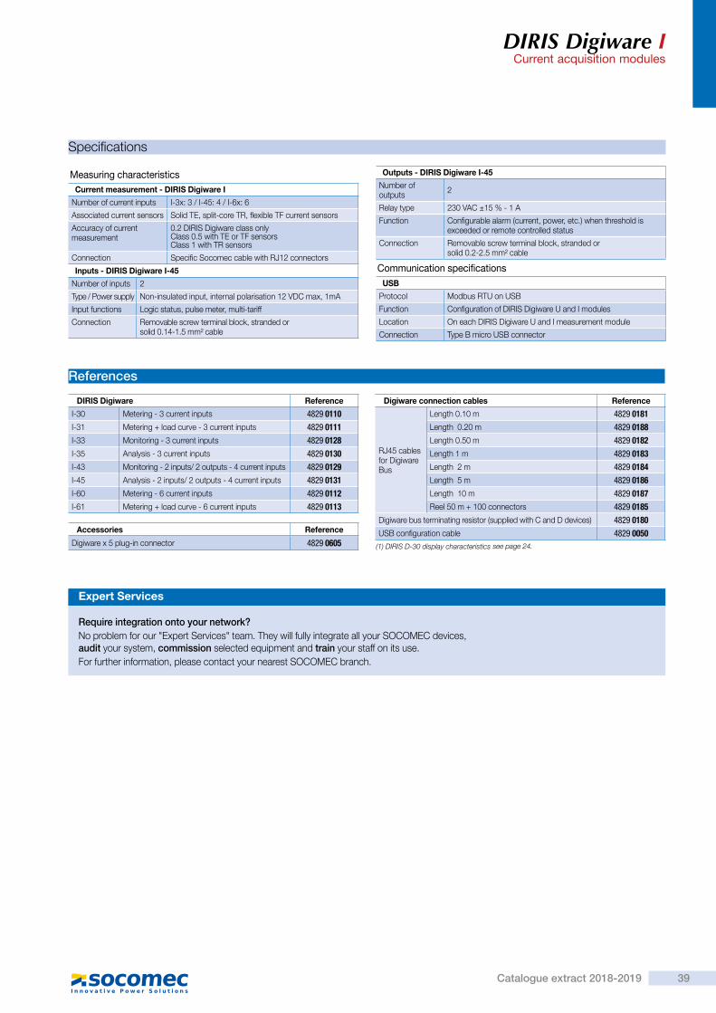
DIRIS Digiware ICurrent acquisition modules
Connections
diris
-dw
_032
_c_1
_x_c
at
Three-phase3P - 3CT (1 three-phase load)
V1 V2 V3 VN
V II01 I02 I03
3
L1
L2
L3
111
diris
-dw
_033
_c_1
_x_c
at
Three-phase3P - 1CT (3 balanced, three-phase loads)
V1 V2 V3 VN
V I
333
I01 I02 I03
L1
L2
L3
111
diris
-b_0
61_a
_1_x
_cat
Single-phase1P+N-1CT (4 single-phase loads)
IV
V1 V2 V3 VN
L1
N
I02 I03I01 I04
1 1 1 1
11
Network and connection examples
1. 0.5 A gG / 0.5 A class CC fuses. 3 Load CT: Current sensor
diris
-dw
_038
_c_1
_x_c
at
Three phase + neutral3P+N - 4CT (1 three-phase load + Neutral measured)
II01 I02 I03 I04
N
V1 V2 V3 VN
V
L1
L2
L3
3 + N
1 1 1
Associated current sensorsVarious types of current sensors are connected to the DIRIS Digiware: closed (TE), split core (TR) or flexible (TF). This range of sensors can be adapted to all types of new or existing installations. A rapid RJ12 connection makes wiring easy and reliable and prevents wiring errors. The DIRIS Digiware system automatically recognises the sensor size and type. This guarantees the overall accuracy of the DIRIS Digiware + current sensor measurement chain.For more information:
I3x
I4x
Dimensions
DIRIS Digiware I-3x / I-6x
I-6xI-3x
90
18 36 6544 15
diris
-dw
_060
_a_1
_x_c
at
DIRIS Digiware I-4x
72
2745
27
21
150
58
45
diris
-dw
_022
_b_1
_x_c
at
DIRIS Digiware ICurrent acquisition modules
Specifications
Measuring characteristicsCurrent measurement - DIRIS Digiware I
Number of current inputs I-3x: 3 / I-45: 4 / I-6x: 6
Associated current sensors Solid TE, split-core TR, flexible TF current sensors
Accuracy of current measurement
0.2 DIRIS Digiware class only Class 0.5 with TE or TF sensors Class 1 with TR sensors
Connection Specific Socomec cable with RJ12 connectors
Inputs - DIRIS Digiware I-45
Number of inputs 2
Type / Power supply Non-insulated input, internal polarisation 12 VDC max, 1mA
Input functions Logic status, pulse meter, multi-tariff
Connection Removable screw terminal block, stranded or solid 0.14-1.5 mm² cable
Outputs - DIRIS Digiware I-45
Number of outputs 2
Relay type 230 VAC ±15 % - 1 A
Function Configurable alarm (current, power, etc.) when threshold is exceeded or remote controlled status
Connection Removable screw terminal block, stranded or solid 0.2-2.5 mm² cable
Communication specificationsUSB
Protocol Modbus RTU on USB
Function Configuration of DIRIS Digiware U and I modules
Location On each DIRIS Digiware U and I measurement module
Connection Type B micro USB connector
References
DIRIS Digiware Reference
I-30 Metering - 3 current inputs 4829 0110I-31 Metering + load curve - 3 current inputs 4829 0111I-33 Monitoring - 3 current inputs 4829 0128I-35 Analysis - 3 current inputs 4829 0130I-43 Monitoring - 2 inputs/ 2 outputs - 4 current inputs 4829 0129I-45 Analysis - 2 inputs/ 2 outputs - 4 current inputs 4829 0131I-60 Metering - 6 current inputs 4829 0112I-61 Metering + load curve - 6 current inputs 4829 0113
Accessories Reference
Digiware x 5 plug-in connector 4829 0605
Digiware connection cables Reference
RJ45 cables for Digiware Bus
Length 0.10 m 4829 0181Length 0.20 m 4829 0188Length 0.50 m 4829 0182Length 1 m 4829 0183Length 2 m 4829 0184Length 5 m 4829 0186Length 10 m 4829 0187Reel 50 m + 100 connectors 4829 0185
Digiware bus terminating resistor (supplied with C and D devices) 4829 0180USB configuration cable 4829 0050
(1) DIRIS D-30 display characteristics
Expert Services
Require integration onto your network?No problem for our "Expert Services" team. They will fully integrate all your SOCOMEC devices, audit your system, commission selected equipment and train your staff on its use.For further information, please contact your nearest SOCOMEC branch.
39Catalogue extract 2018-2019
see page 24.

Cur
rent
sen
sors
TE sensorsSolid current sensorsused with DIRIS Digiware, DIRIS A-40 and DIRIS B
TE solid sensors
Function
TE smart current sensors measure the load currents of an electrical system and send the data to meters and measurement hubs via an RJ12 plug-and-play output. Thanks to a wide measurement range, TE current sensors cover the full current range of 5 to 2000 A, with 7 references. TE solid current sensors can be connected to DIRIS Digiware and DIRIS B-30 via a rapid RJ12 connection.Numerous accessories are available to aid the installation of sensors in any type of cabinet.
> Plug & Play > Accuracy as per standard IEC 61557-12
> Installation
Strong points
Advantages
Plug & Play • A rapid RJ12 connection makes wiring easy and reliable and prevents wiring errors. This also allows automatic detection of the sensor type and size/transformation ratio.
• The sensors can be installed in both directions.
Accuracy as per standard IEC 61557-12 • Class 0.5 for the global measuring chain (measurement hub + TE current sensors) from 2 to 120% of the nominal current In.
Installation • The TE solid sensor range is specially designed for new installations, and has the same pitch as the most common protective devices.
> Industry > Building > Infrastructure > Data center
The solution for
diris
-t_0
10_a
_1_c
at
diris
-t_0
03_a
_1_c
at
tore
_065
_a
> IEC 61557-12
> ISO 14025
> UL
Conformity to standards
diris
-t_0
03_a
_1_c
at
tore
_065
_a
new
> Find the best DIRIS Digiware configuration:www.meter-selector.com
Create your project
TE sensorsSolid current sensors
used with DIRIS Digiware, DIRIS A-40 and DIRIS B
Mounting
Connections
DIN rail mounted
diris-t_033_a_1_cat
diris-t_036_a_1_cat
Bar mounting
diris-t_034_a_1_cat
Back-plate mounting
Staggered assembly
TE-18 / TE-35 / TE-45 / TE-55
diris
-t_0
05_a
_1_c
at
diris-t_035_a_1_cat
Cable mountingLinear assembly with the protective devices
TE-25 / TE-35 / TE-45 / TE-55 / TE-90
diris
-t_0
05_a
_1_c
at
TE-90 clamps
diris
-t_0
48_a
diris
-t_0
49_a
diris-b_033_a_cat
TE / TR / TF current sensors
TR
TF
TE
RJ12 Connection
DIRIS B-30 or
DIRIS DIGIWARE I
40 Catalogue extract 2018-2019
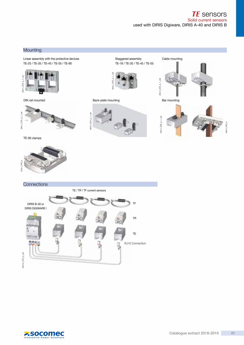
Cur
rent
sen
sors
TE sensorsSolid current sensorsused with DIRIS Digiware, DIRIS A-40 and DIRIS B
TE solid sensors
Function
TE smart current sensors measure the load currents of an electrical system and send the data to meters and measurement hubs via an RJ12 plug-and-play output. Thanks to a wide measurement range, TE current sensors cover the full current range of 5 to 2000 A, with 7 references. TE solid current sensors can be connected to DIRIS Digiware and DIRIS B-30 via a rapid RJ12 connection.Numerous accessories are available to aid the installation of sensors in any type of cabinet.
> Plug & Play > Accuracy as per standard IEC 61557-12
> Installation
Strong points
Advantages
Plug & Play • A rapid RJ12 connection makes wiring easy and reliable and prevents wiring errors. This also allows automatic detection of the sensor type and size/transformation ratio.
• The sensors can be installed in both directions.
Accuracy as per standard IEC 61557-12 • Class 0.5 for the global measuring chain (measurement hub + TE current sensors) from 2 to 120% of the nominal current In.
Installation • The TE solid sensor range is specially designed for new installations, and has the same pitch as the most common protective devices.
> Industry > Building > Infrastructure > Data center
The solution for
diris
-t_0
10_a
_1_c
at
diris
-t_0
03_a
_1_c
at
tore
_065
_a
> IEC 61557-12
> ISO 14025
> UL
Conformity to standards
diris
-t_0
03_a
_1_c
at
tore
_065
_a
new
> Find the best DIRIS Digiware configuration:www.meter-selector.com
Create your project
TE sensorsSolid current sensors
used with DIRIS Digiware, DIRIS A-40 and DIRIS B
Mounting
Connections
DIN rail mounted
diris-t_033_a_1_cat
diris-t_036_a_1_cat
Bar mounting
diris-t_034_a_1_cat
Back-plate mounting
Staggered assembly
TE-18 / TE-35 / TE-45 / TE-55
diris
-t_0
05_a
_1_c
at
diris-t_035_a_1_cat
Cable mountingLinear assembly with the protective devices
TE-25 / TE-35 / TE-45 / TE-55 / TE-90
diris
-t_0
05_a
_1_c
at
TE-90 clamps
diris
-t_0
48_a
diris
-t_0
49_a
diris-b_033_a_cat
TE / TR / TF current sensors
TR
TF
TE
RJ12 Connection
DIRIS B-30 or
DIRIS DIGIWARE I
41Catalogue extract 2018-2019

TE sensorsSolid current sensorsused with DIRIS Digiware, DIRIS A-40 and DIRIS B
Dimensions (mm)
TE - Solid current sensorsTE-18
PL
HØ
Model Nominal current range (A) Actual coverage range (A) Pitch (mm) H x W x D (mm) F (mm) T (mm)
TE-18 5 … 20 / 25 ... 63 0.1 … 24 / 0.5 … 75 18 45 x 28 x 20 8.6 -
TE-25 40 … 160 0.8 … 192 25 65 x 25 x 32.5 13.5 x 13.5 17.5
TE-35 63 … 250 1.26 … 300 35 71 x 35 x 32.5 21 x 21 17.5
TE-45 160 … 630 3.2 … 756 45 86 x 45 x 32.5 31 x 31 19.5
TE-55 400 … 1000 8 … 1200 55 100 x 55 x 32.5 41 x 41 21.5
TE-90 600 … 2000 12 … 2400 90 126 x 90 x 24.6 64 x 64 -
TE-25 / TE-35 / TE-45 / TE-55 TE-90
PL
H
T
= F =
==
==
1
1
P2.2L
36
19.7
= F =
H
diris
-t_0
23_b
_1_f
r_ca
t
diris
-t_0
47_a
_1_f
r_ca
t
1. Switch mounting
Mounting accessories
diris
-t_0
42_a
- 0
43_a
- 0
44_a
- 0
45_a
Mounting accessories delivered with TE sensors:
Switch mounting TE-18 TE-25
TE-35TE-45TE-55 TE-90
DIN rail and back-plate 1 pc 2 pcs
DIN rail 2 pcs 2 pcs
Back-plate 4 pcs 4 pcs 6 pcs
Busbar 2 pcs
Compatible accessoriesAdapter for CT with 5A secondary
• With this adapter you can use a current transformer with a 5 A output on the DIRIS Digiware and DIRIS B-30.For use with standard 5 A sensors for measuring applications of > 2000 A. The dimensions are the same as the TE-18.
Coupling link • Associated with the TE range, this accessory is for inter-connecting the sensors when linear or staggered mounted.
Sealable cover • Using a sealable cover guarantees the immunity of the sensor connection on TE/TR/TF current sensors.
diris
-t_0
20_a
_1_c
at
diris
-t_0
46_a
_1_c
at
diris
-t_0
41_a
_1_c
atTE sensors
Solid current sensorsused with DIRIS Digiware, DIRIS A-40 and DIRIS B
Specifications
References
Accessories Reference
Coupling link (20 linear assembly parts and 10 for staggered assembly) 4829 0598CT/5A adapter (measurements of >2000 A) (max primary current 10000 A/5/A) 4829 0599Sealable caps (20 pieces) 4829 0600
RJ12 connection cables
Cable length (m)
0.1 0.2 0.3 0.5 1 2 5 1050 m reel + 100
connectors
Number of cables Reference Reference Reference Reference Reference Reference Reference Reference Reference1 - - - - - - 4829 0602 4829 0603 4829 06013 4829 0580 4829 0581 4829 0582 4829 0595 4829 0583 4829 0584 - - -4 - - - 4829 0596 4829 0588 4829 0589 - - -6 4829 0590 4829 0591 4829 0592 4829 0597 4829 0593 4829 0594 - - -
TE - Solid current sensorsModel TE-18 TE-18 TE-25 TE-35 TE-45 TE-55 TE-90
Nominal current range In (A) 5 … 20 25 … 63 40 … 160 63 … 250 160 … 630 400 … 1000 600 … 2000
Actual coverage range (A) 0.1 … 24 0.5 … 75 0.8 … 192 1.26 … 300 3.2 … 756 8 … 1200 12 … 2400
Max. current (A) 24 75.6 192 300 756 1200 2400
Weight (g) 24 24 69 89 140 187 163
Max. voltage (phase/neutral) 300 V
Rated withstand voltage 3 kV
Frequency 50/60 Hz
Intermittent overload 10 x In over 1 sec
Measurement category CAT III
Protection degree IP30 / IK06
Operating temperature -10 … +70°C
Storage temperature -25 … +85°C
Relative humidity 95% RH non-condensing
Altitude < 2000 m
Connection Socomec RJ12 cable
Model Nominal current range (A) Actual coverage range (A) Pitch (mm) Reference
TE-18 5 … 20 0.1 … 24 18 4829 0500TE-18 25 … 63 0.5 … 75 18 4829 0501TE-25 40 … 160 0.8 … 192 25 4829 0502TE-35 63 … 250 1.26 … 300 35 4829 0503TE-45 160 … 630 3.2 … 756 45 4829 0504TE-55 400 … 1000 8 … 1200 55 4829 0505TE-90 600 … 2000 12 … 2400 90 4829 0506
42 Catalogue extract 2018-2019
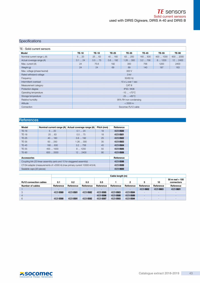
TE sensorsSolid current sensorsused with DIRIS Digiware, DIRIS A-40 and DIRIS B
Dimensions (mm)
TE - Solid current sensorsTE-18
PL
HØ
Model Nominal current range (A) Actual coverage range (A) Pitch (mm) H x W x D (mm) F (mm) T (mm)
TE-18 5 … 20 / 25 ... 63 0.1 … 24 / 0.5 … 75 18 45 x 28 x 20 8.6 -
TE-25 40 … 160 0.8 … 192 25 65 x 25 x 32.5 13.5 x 13.5 17.5
TE-35 63 … 250 1.26 … 300 35 71 x 35 x 32.5 21 x 21 17.5
TE-45 160 … 630 3.2 … 756 45 86 x 45 x 32.5 31 x 31 19.5
TE-55 400 … 1000 8 … 1200 55 100 x 55 x 32.5 41 x 41 21.5
TE-90 600 … 2000 12 … 2400 90 126 x 90 x 24.6 64 x 64 -
TE-25 / TE-35 / TE-45 / TE-55 TE-90
PL
H
T
= F =
==
==
1
1
P2.2L
36
19.7
= F =
H
diris
-t_0
23_b
_1_f
r_ca
t
diris
-t_0
47_a
_1_f
r_ca
t
1. Switch mounting
Mounting accessories
diris
-t_0
42_a
- 0
43_a
- 0
44_a
- 0
45_a
Mounting accessories delivered with TE sensors:
Switch mounting TE-18 TE-25
TE-35TE-45TE-55 TE-90
DIN rail and back-plate 1 pc 2 pcs
DIN rail 2 pcs 2 pcs
Back-plate 4 pcs 4 pcs 6 pcs
Busbar 2 pcs
Compatible accessoriesAdapter for CT with 5A secondary
• With this adapter you can use a current transformer with a 5 A output on the DIRIS Digiware and DIRIS B-30.For use with standard 5 A sensors for measuring applications of > 2000 A. The dimensions are the same as the TE-18.
Coupling link • Associated with the TE range, this accessory is for inter-connecting the sensors when linear or staggered mounted.
Sealable cover • Using a sealable cover guarantees the immunity of the sensor connection on TE/TR/TF current sensors.
diris
-t_0
20_a
_1_c
at
diris
-t_0
46_a
_1_c
at
diris
-t_0
41_a
_1_c
at
TE sensorsSolid current sensors
used with DIRIS Digiware, DIRIS A-40 and DIRIS B
Specifications
References
Accessories Reference
Coupling link (20 linear assembly parts and 10 for staggered assembly) 4829 0598CT/5A adapter (measurements of >2000 A) (max primary current 10000 A/5/A) 4829 0599Sealable caps (20 pieces) 4829 0600
RJ12 connection cables
Cable length (m)
0.1 0.2 0.3 0.5 1 2 5 1050 m reel + 100
connectors
Number of cables Reference Reference Reference Reference Reference Reference Reference Reference Reference1 - - - - - - 4829 0602 4829 0603 4829 06013 4829 0580 4829 0581 4829 0582 4829 0595 4829 0583 4829 0584 - - -4 - - - 4829 0596 4829 0588 4829 0589 - - -6 4829 0590 4829 0591 4829 0592 4829 0597 4829 0593 4829 0594 - - -
TE - Solid current sensorsModel TE-18 TE-18 TE-25 TE-35 TE-45 TE-55 TE-90
Nominal current range In (A) 5 … 20 25 … 63 40 … 160 63 … 250 160 … 630 400 … 1000 600 … 2000
Actual coverage range (A) 0.1 … 24 0.5 … 75 0.8 … 192 1.26 … 300 3.2 … 756 8 … 1200 12 … 2400
Max. current (A) 24 75.6 192 300 756 1200 2400
Weight (g) 24 24 69 89 140 187 163
Max. voltage (phase/neutral) 300 V
Rated withstand voltage 3 kV
Frequency 50/60 Hz
Intermittent overload 10 x In over 1 sec
Measurement category CAT III
Protection degree IP30 / IK06
Operating temperature -10 … +70°C
Storage temperature -25 … +85°C
Relative humidity 95% RH non-condensing
Altitude < 2000 m
Connection Socomec RJ12 cable
Model Nominal current range (A) Actual coverage range (A) Pitch (mm) Reference
TE-18 5 … 20 0.1 … 24 18 4829 0500TE-18 25 … 63 0.5 … 75 18 4829 0501TE-25 40 … 160 0.8 … 192 25 4829 0502TE-35 63 … 250 1.26 … 300 35 4829 0503TE-45 160 … 630 3.2 … 756 45 4829 0504TE-55 400 … 1000 8 … 1200 55 4829 0505TE-90 600 … 2000 12 … 2400 90 4829 0506
43Catalogue extract 2018-2019

Cur
rent
sen
sors
TR / iTR sensorsSplit-core AC current sensorsused with DIRIS Digiware, DIRIS A-40 and DIRIS B
TR Split-core current sensors
Function
The split-core current sensors in the TR and iTR ranges enable the current of an electrical installation to be measured. Used with power monitoring device DIRIS Digiware, DIRIS A-40, DIRIS B, they make it possible to perform measurements between 25 and 600 A,with guaranteed accuracy. The RJ12 connection provides quick connections, and the integrated intelligence prevents any configuration errors.The sensors in the iTR range revolutionise the world of measurement and provide access to VirtualMonitor status monitoring technologies and to AutoCorrect automatic configuration.
> Smart sensors > PreciSense technology: Global accuracy in accordance with the IEC 61557-12 standard.
> Easy installation and configuration.
Strong points
Advantages of the TR and iTR ranges
Smart sensors • Sensors with an extended operational range.
• Automatic detection of rating. • Secured disconnection of load. • Quick connection via RJ12 and identification of cable by colour code.
Accurate • Measurement precision guaranteed in acc. with standard IEC 61557-12 : class 0.5 (iTR) or 1 (TR) for the global measuring chain from 2 to 120% of In.
> Retrofit applications > Industry > Building > Infrastructure > Data centers
The solution for
> IEC 61557-12
> ISO 14025
> UL
Compliance with standards
Integrated technologies(1)
For more information, see page
(1) AutoCorrect and VirtualMonitor are only available with iTR sensors.
TR Split-core current sensors
tore
_074
_a.e
ps
Unique advantages of the iTR range
VirtualMonitor technologyVirtualMonitor technology makes it possible to monitor the status of protective devices: • Throughout your electrical installation. • Remotely and in real-time. • Without additional hardware or wiring.
AutoCorrect technologyAutoCorrect technology guarantees that your measurement system will function properly through: • Automatic installation verification (by checking phase sequencing and automatic configuration of the direction of current).
• Correction of errors.
> Find the best DIRIS Digiware configuration:www.meter-selector.com
Create your project
TR / iTR sensorsSplit-core AC current sensors
used with DIRIS Digiware, DIRIS A-40 and DIRIS B
Installation Dimensions
Cable mounting TR-10 / TR-14 / TR-21 / TR-32
ModelNominal current
range (A)Actual coverage
range (A)A
(mm)B
(mm)C
(mm)D
(mm)E
(mm)Ø
(mm)
TR / iTR-10 25 ... 63 0.5 … 90 44 26 28 - - 10
TR / iTR-14 40 ... 160 0.64 … 120 67 29 28 14 15 14
TR / iTR-21 63 ... 250 1.26 … 200 65 37 43 21 23 21
TR / iTR-32 160 ... 600 4 … 720 86 53 47 32 33 32
Technical characteristics
References
Model TR-10 iTR-10 TR-14 iTR-14 TR-21 iTR-21 TR-32 iTR-32
Nominal current range In (A) 25 ... 63 40 ... 160 63 ... 250 160 ... 600
Actual coverage range (A) 0.5 ... 75.6 0.8 ... 192 1.26 ... 300 3.2 ... 720
Max. current (A) 75.6 192 300 720
Weight (g) 74 117 211 311
Max. voltage (phase/neutral) 300 V
Rated withstand voltage 3 kV
Frequency 50/60 Hz
Intermittent overload 10 x In for 1 s
Measurement category CAT III
Global class used with Diris Digiware / A-40 / B-10 / B-30 Class 1 Class 0.5 Class 1 Class 0.5 Class 1 Class 0.5 Class 1 Class 0.5
Protection degree IP20 / IK07
Operating temperature range -10 to +70°C -10°...+55°C
Storage temperature range -25 to +85°C
Relative humidity 95% RH non-condensing
Altitude < 2000 m
Connection Socomec RJ12 cable
RJ12 connection cables
Cable length (m)
0.1 0.2 0.3 0.5 1 2 5 1050 m reel + 100
connectors
Number of cables Part number Reference Reference Reference Reference Reference Reference Reference Reference1 - - - - - - 4829 0602 4829 0603 4829 06013 4829 0580 4829 0581 4829 0582 4829 0595 4829 0583 4829 0584 - - -4 - - - 4829 0596 4829 0588 4829 0589 - - -6 4829 0590 4829 0591 4829 0592 4829 0597 4829 0593 4829 0594 - - -
ModelNominal current
range (A)Actual coverage
range (A) Ø (mm) Part number
TR-10 25 … 63 0.5 ... 75 10 4829 0555TR-14 40 … 160 0.8 ... 192 14 4829 0556TR-21 63 … 250 1.26 ... 300 21 4829 0557TR-32 160 … 600 3.2 … 720 32 4829 0558
ModelNominal current
range (A)Actual coverage
range (A) Ø (mm) Part number
iTR-10 25 … 63 0.5 … 75 10 4829 0655iTR-14 40 … 160 0.8 … 192 14 4829 0656iTR-21 63 … 250 1.26 … 300 21 4829 0657iTR-32 160 … 600 3.2 … 720 32 4829 0658
diris
-t_0
37_b
_1_c
at.e
ps
diris
-t_0
38_b
_1_c
at.e
ps
D
A
E
B C
diris
-t_0
24_c
_1_x
_cat
.eps
44 Catalogue extract 2018-2019
4.

Cur
rent
sen
sors
TR / iTR sensorsSplit-core AC current sensorsused with DIRIS Digiware, DIRIS A-40 and DIRIS B
TR Split-core current sensors
Function
The split-core current sensors in the TR and iTR ranges enable the current of an electrical installation to be measured. Used with power monitoring device DIRIS Digiware, DIRIS A-40, DIRIS B, they make it possible to perform measurements between 25 and 600 A,with guaranteed accuracy. The RJ12 connection provides quick connections, and the integrated intelligence prevents any configuration errors.The sensors in the iTR range revolutionise the world of measurement and provide access to VirtualMonitor status monitoring technologies and to AutoCorrect automatic configuration.
> Smart sensors > PreciSense technology: Global accuracy in accordance with the IEC 61557-12 standard.
> Easy installation and configuration.
Strong points
Advantages of the TR and iTR ranges
Smart sensors • Sensors with an extended operational range.
• Automatic detection of rating. • Secured disconnection of load. • Quick connection via RJ12 and identification of cable by colour code.
Accurate • Measurement precision guaranteed in acc. with standard IEC 61557-12 : class 0.5 (iTR) or 1 (TR) for the global measuring chain from 2 to 120% of In.
> Retrofit applications > Industry > Building > Infrastructure > Data centers
The solution for
> IEC 61557-12
> ISO 14025
> UL
Compliance with standards
Integrated technologies(1)
For more information, see page
(1) AutoCorrect and VirtualMonitor are only available with iTR sensors.
TR Split-core current sensors
tore
_074
_a.e
ps
Unique advantages of the iTR range
VirtualMonitor technologyVirtualMonitor technology makes it possible to monitor the status of protective devices: • Throughout your electrical installation. • Remotely and in real-time. • Without additional hardware or wiring.
AutoCorrect technologyAutoCorrect technology guarantees that your measurement system will function properly through: • Automatic installation verification (by checking phase sequencing and automatic configuration of the direction of current).
• Correction of errors.
> Find the best DIRIS Digiware configuration:www.meter-selector.com
Create your project
TR / iTR sensorsSplit-core AC current sensors
used with DIRIS Digiware, DIRIS A-40 and DIRIS B
Installation Dimensions
Cable mounting TR-10 / TR-14 / TR-21 / TR-32
ModelNominal current
range (A)Actual coverage
range (A)A
(mm)B
(mm)C
(mm)D
(mm)E
(mm)Ø
(mm)
TR / iTR-10 25 ... 63 0.5 … 90 44 26 28 - - 10
TR / iTR-14 40 ... 160 0.64 … 120 67 29 28 14 15 14
TR / iTR-21 63 ... 250 1.26 … 200 65 37 43 21 23 21
TR / iTR-32 160 ... 600 4 … 720 86 53 47 32 33 32
Technical characteristics
References
Model TR-10 iTR-10 TR-14 iTR-14 TR-21 iTR-21 TR-32 iTR-32
Nominal current range In (A) 25 ... 63 40 ... 160 63 ... 250 160 ... 600
Actual coverage range (A) 0.5 ... 75.6 0.8 ... 192 1.26 ... 300 3.2 ... 720
Max. current (A) 75.6 192 300 720
Weight (g) 74 117 211 311
Max. voltage (phase/neutral) 300 V
Rated withstand voltage 3 kV
Frequency 50/60 Hz
Intermittent overload 10 x In for 1 s
Measurement category CAT III
Global class used with Diris Digiware / A-40 / B-10 / B-30 Class 1 Class 0.5 Class 1 Class 0.5 Class 1 Class 0.5 Class 1 Class 0.5
Protection degree IP20 / IK07
Operating temperature range -10 to +70°C -10°...+55°C
Storage temperature range -25 to +85°C
Relative humidity 95% RH non-condensing
Altitude < 2000 m
Connection Socomec RJ12 cable
RJ12 connection cables
Cable length (m)
0.1 0.2 0.3 0.5 1 2 5 1050 m reel + 100
connectors
Number of cables Part number Reference Reference Reference Reference Reference Reference Reference Reference1 - - - - - - 4829 0602 4829 0603 4829 06013 4829 0580 4829 0581 4829 0582 4829 0595 4829 0583 4829 0584 - - -4 - - - 4829 0596 4829 0588 4829 0589 - - -6 4829 0590 4829 0591 4829 0592 4829 0597 4829 0593 4829 0594 - - -
ModelNominal current
range (A)Actual coverage
range (A) Ø (mm) Part number
TR-10 25 … 63 0.5 ... 75 10 4829 0555TR-14 40 … 160 0.8 ... 192 14 4829 0556TR-21 63 … 250 1.26 ... 300 21 4829 0557TR-32 160 … 600 3.2 … 720 32 4829 0558
ModelNominal current
range (A)Actual coverage
range (A) Ø (mm) Part number
iTR-10 25 … 63 0.5 … 75 10 4829 0655iTR-14 40 … 160 0.8 … 192 14 4829 0656iTR-21 63 … 250 1.26 … 300 21 4829 0657iTR-32 160 … 600 3.2 … 720 32 4829 0658
diris
-t_0
37_b
_1_c
at.e
ps
diris
-t_0
38_b
_1_c
at.e
ps
D
A
E
B C
diris
-t_0
24_c
_1_x
_cat
.eps
45Catalogue extract 2018-2019

Cur
rent
sen
sors
TF sensorsFlexible current sensorsused with DIRIS Digiware, DIRIS A-40 and DIRIS B
TF Flexible current sensors
Function
TF smart current sensors measure the load currents of an electrical system and send the data to meters and measurement hubs via an RJ12 plug-and-play output. Thanks to a wide measurement range, TF current sensors cover the full current range of 150 to 6000 A, with 3 references. TF flexible current sensors can be connected to DIRIS Digiware and DIRIS B-30 via a rapid RJ12 connection.
> Plug & Play > Accuracy as per standard IEC 61557-12
> Installation
Strong points
Advantages
Plug & Play • A rapid RJ12 connection makes wiring easy and reliable and prevents wiring errors. This also allows automatic detection of the sensor type and size/transformation ratio.
• The sensors can be installed in both directions.
Accuracy as per standard IEC 61557-12 • Class 0.5 for the global measuring chain (measurement hub + TF current sensors) from 2 to 120% of the nominal current In.
Installation • The TF flexible sensor range is specially designed for existing installations restricted by strict integration constraints or with high-intensity currents.
> Industry > Building > Infrastructure > Data center
The solution for
diris
-t_0
16_a
_1_c
at
> IEC 61557-12
> ISO 14025
> UL
Conformity to standards
> Find the best DIRIS Digiware configuration:www.meter-selector.com
Create your project
TF sensorsFlexible current sensors
used with DIRIS Digiware, DIRIS A-40 and DIRIS B
Mounting
Dimensions
Connections
diris
-t_0
39_a
_1_c
at
diris
-t_0
40_a
_1_c
at
Bar mountingCable mounting
TF-55 TF-120 / TF-300
18
85
Ø 6
L Ø
1500
383818
85 Ø 11
L
Ø
1500
Model Nominal current range (A) Actual coverage range (A) Ø loop (mm) L = Loop length (mm)TF-55 150 … 600 3 … 720 55 182TF-120 500 … 2000 10 … 2400 120 376TF-300 1600 … 6000 32 … 7200 300 942
diris
-t_0
27_c
_1_x
_cat
diris
-t_0
28_a
_1_x
_cat
AccessoriesSealable cover • Using a sealable cover guarantees the immunity of the sensor connection on TE/TR/TF current sensors.
diris
-t_0
46_a
_1_c
at
Specifications ReferencesModel TF-55 TF-120 TF-300Nominal current range In (A) 150 … 600 500 … 2000 1600 … 6000Actual coverage range (A) 3 … 720 10 … 2400 32 … 7200Weight (g) 114 142 220Max. voltage (phase/neutral) 600 VRated withstand voltage 3.6 kVFrequency 50 / 60 HzIntermittent overload 10 x In for 1 sMeasurement category CAT IIIProtection degree IP30 / IK07Operating temperature -10 … +70°CStorage temperature -25 … +75°CRelative humidity 95% RH non-condensingAltitude < 2000 m
Connection Socomec cable or equivalent RJ12 straight, twisted pair, unshielded 300 V cat. III cable. -40 / +85 °C
Accessories Reference
Sealable caps (20 pieces) 4829 0600
ModelNominal current
range (A)
Actual coverage range (A)
Ø loop (mm) Reference
TF-55 150 … 600 3 … 720 55 4829 0570TF-120 500 … 2000 10 … 2400 120 4829 0571TF-300 1600 … 6000 32 … 7200 300 4829 0572
RJ12 connection cables
Cable length (m)
0.1 0.2 0.3 0.5 1 2 5 1050 m reel + 100
connectors
Number of cables Reference Reference Reference Reference Reference Reference Reference Reference Reference1 - - - - - - 4829 0602 4829 0603 4829 06013 4829 0580 4829 0581 4829 0582 4829 0595 4829 0583 4829 0584 - - -4 - - - 4829 0596 4829 0588 4829 0589 - - -6 4829 0590 4829 0591 4829 0592 4829 0597 4829 0593 4829 0594 - - -
diris
-b_0
33_a
_cat
TE / TR / TF current sensors
TR
TF
TE
RJ12 Connection
DIRIS B-30
or DIRIS DIGIWARE I
46 Catalogue extract 2018-2019
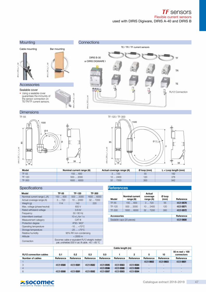
Cur
rent
sen
sors
TF sensorsFlexible current sensorsused with DIRIS Digiware, DIRIS A-40 and DIRIS B
TF Flexible current sensors
Function
TF smart current sensors measure the load currents of an electrical system and send the data to meters and measurement hubs via an RJ12 plug-and-play output. Thanks to a wide measurement range, TF current sensors cover the full current range of 150 to 6000 A, with 3 references. TF flexible current sensors can be connected to DIRIS Digiware and DIRIS B-30 via a rapid RJ12 connection.
> Plug & Play > Accuracy as per standard IEC 61557-12
> Installation
Strong points
Advantages
Plug & Play • A rapid RJ12 connection makes wiring easy and reliable and prevents wiring errors. This also allows automatic detection of the sensor type and size/transformation ratio.
• The sensors can be installed in both directions.
Accuracy as per standard IEC 61557-12 • Class 0.5 for the global measuring chain (measurement hub + TF current sensors) from 2 to 120% of the nominal current In.
Installation • The TF flexible sensor range is specially designed for existing installations restricted by strict integration constraints or with high-intensity currents.
> Industry > Building > Infrastructure > Data center
The solution for
diris
-t_0
16_a
_1_c
at
> IEC 61557-12
> ISO 14025
> UL
Conformity to standards
> Find the best DIRIS Digiware configuration:www.meter-selector.com
Create your project
TF sensorsFlexible current sensors
used with DIRIS Digiware, DIRIS A-40 and DIRIS B
Mounting
Dimensions
Connections
diris
-t_0
39_a
_1_c
at
diris
-t_0
40_a
_1_c
atBar mountingCable mounting
TF-55 TF-120 / TF-300
18
85
Ø 6
L Ø
1500
383818
85 Ø 11
L
Ø
1500
Model Nominal current range (A) Actual coverage range (A) Ø loop (mm) L = Loop length (mm)TF-55 150 … 600 3 … 720 55 182TF-120 500 … 2000 10 … 2400 120 376TF-300 1600 … 6000 32 … 7200 300 942
diris
-t_0
27_c
_1_x
_cat
diris
-t_0
28_a
_1_x
_cat
AccessoriesSealable cover • Using a sealable cover guarantees the immunity of the sensor connection on TE/TR/TF current sensors.
diris
-t_0
46_a
_1_c
at
Specifications ReferencesModel TF-55 TF-120 TF-300Nominal current range In (A) 150 … 600 500 … 2000 1600 … 6000Actual coverage range (A) 3 … 720 10 … 2400 32 … 7200Weight (g) 114 142 220Max. voltage (phase/neutral) 600 VRated withstand voltage 3.6 kVFrequency 50 / 60 HzIntermittent overload 10 x In for 1 sMeasurement category CAT IIIProtection degree IP30 / IK07Operating temperature -10 … +70°CStorage temperature -25 … +75°CRelative humidity 95% RH non-condensingAltitude < 2000 m
Connection Socomec cable or equivalent RJ12 straight, twisted pair, unshielded 300 V cat. III cable. -40 / +85 °C
Accessories Reference
Sealable caps (20 pieces) 4829 0600
ModelNominal current
range (A)
Actual coverage range (A)
Ø loop (mm) Reference
TF-55 150 … 600 3 … 720 55 4829 0570TF-120 500 … 2000 10 … 2400 120 4829 0571TF-300 1600 … 6000 32 … 7200 300 4829 0572
RJ12 connection cables
Cable length (m)
0.1 0.2 0.3 0.5 1 2 5 1050 m reel + 100
connectors
Number of cables Reference Reference Reference Reference Reference Reference Reference Reference Reference1 - - - - - - 4829 0602 4829 0603 4829 06013 4829 0580 4829 0581 4829 0582 4829 0595 4829 0583 4829 0584 - - -4 - - - 4829 0596 4829 0588 4829 0589 - - -6 4829 0590 4829 0591 4829 0592 4829 0597 4829 0593 4829 0594 - - -
diris
-b_0
33_a
_cat
TE / TR / TF current sensors
TR
TF
TE
RJ12 Connection
DIRIS B-30
or DIRIS DIGIWARE I
47Catalogue extract 2018-2019

Mul
ti-ci
rcui
t m
eter
ing
&
mea
sure
men
t
Function
The DIRIS Digiware U-3xdc module measures DC voltage for the entire system. It measures up to 180 VDC with a direct connection and is therefore compatible with typical nominal voltages (24 VDC, 48 VDC…).The voltage adaptors make the system compatible with all voltage levels up to 1650 VDC to respond to the needs of all applications.The RJ45 Digiware Bus transmits voltage measurements along with power supply and communication to all connected products.
Advantages
Single voltage measurement • 1 single voltage measurement point for the entire system.
• Single point of protection for the voltage measurement.
• No hazardous voltage on panel doors.
Flexible • The voltage adaptors make the measurement system compatible with all DC electrical networks.
Plug & Play • Easy to configure from DIRIS Digiware D interfaces or from the Easy Config configuration software.
> Data centre > Telecommunication > Renewable power > Transportation
The solution for
diris
-dw
_116
_a
diris
-dw
_005
_a_c
at
DIRIS Digiware U-31dc/U-32dc DIRIS Digiware U500dc/U1000dc/U1500dc adaptor
Configuration with EasyConfig,
DIRIS Digiware UdcDC voltage acquisition module
> Centralisation of voltage measurement
> Flexible > Plug & Play
Strong points
> IEC 61557-12
> ISO 14025
> UL E257746
Compliance with standards
RJ45 (Digiware Bus) cables are available.
RJ45Communication
new
DIRIS Digiware UdcDC voltage acquisition module
Application DC voltage measurement
DIRIS Digiware Udc U-31dc U-32dc
Nominal voltage range 24 … 48 VDC 60 … 150 VDC
Measuring range (min-max) 19.2 … 60 VDC 48 … 180 VDC
Multi-measurement
DC voltage (VDC) • •
Power quality
V ripple (voltage ripple) • •
Vrms • •
Alarms
Thresholds and combinations • •
Trends
Average values • •
Format
Width/number of modules 18 mm / 1
Application DC voltage adaptors
DIRIS Digiware Udc U500dc U1000dc U1500dc
Max. voltage range 200 … 600 VDC 400 … 1200 VDC 1200 … 1650 VDC
Association
U-32dc • • •
Format
Width/number of modules 54 mm / 3
ConnectionsConnecting DIRIS Digiware DC adaptors
380.4 v
DIRIS Digiware Ddisplay unit
Digiware bus
Voltage input
or
End-of-line resistor RJ45
I-3xdc with 3 inputs to DC sensorsU-32 dc
RS485 Modbuscommunication
Udc adaptor
24 VDCpower supply
+
- (0 V)
+
-
diris
-dw
_132
_a_e
n.ai
48 Catalogue extract 2018-2019

Mul
ti-ci
rcui
t m
eter
ing
&
mea
sure
men
t
Function
The DIRIS Digiware U-3xdc module measures DC voltage for the entire system. It measures up to 180 VDC with a direct connection and is therefore compatible with typical nominal voltages (24 VDC, 48 VDC…).The voltage adaptors make the system compatible with all voltage levels up to 1650 VDC to respond to the needs of all applications.The RJ45 Digiware Bus transmits voltage measurements along with power supply and communication to all connected products.
Advantages
Single voltage measurement • 1 single voltage measurement point for the entire system.
• Single point of protection for the voltage measurement.
• No hazardous voltage on panel doors.
Flexible • The voltage adaptors make the measurement system compatible with all DC electrical networks.
Plug & Play • Easy to configure from DIRIS Digiware D interfaces or from the Easy Config configuration software.
> Data centre > Telecommunication > Renewable power > Transportation
The solution for
diris
-dw
_116
_a
diris
-dw
_005
_a_c
at
DIRIS Digiware U-31dc/U-32dc DIRIS Digiware U500dc/U1000dc/U1500dc adaptor
Configuration with EasyConfig,
DIRIS Digiware UdcDC voltage acquisition module
> Centralisation of voltage measurement
> Flexible > Plug & Play
Strong points
> IEC 61557-12
> ISO 14025
> UL E257746
Compliance with standards
RJ45 (Digiware Bus) cables are available.
RJ45
Communication
new
DIRIS Digiware UdcDC voltage acquisition module
Application DC voltage measurement
DIRIS Digiware Udc U-31dc U-32dc
Nominal voltage range 24 … 48 VDC 60 … 150 VDC
Measuring range (min-max) 19.2 … 60 VDC 48 … 180 VDC
Multi-measurement
DC voltage (VDC) • •
Power quality
V ripple (voltage ripple) • •
Vrms • •
Alarms
Thresholds and combinations • •
Trends
Average values • •
Format
Width/number of modules 18 mm / 1
Application DC voltage adaptors
DIRIS Digiware Udc U500dc U1000dc U1500dc
Max. voltage range 200 … 600 VDC 400 … 1200 VDC 1200 … 1650 VDC
Association
U-32dc • • •
Format
Width/number of modules 54 mm / 3
ConnectionsConnecting DIRIS Digiware DC adaptors
380.4 v
DIRIS Digiware Ddisplay unit
Digiware bus
Voltage input
or
End-of-line resistor RJ45
I-3xdc with 3 inputs to DC sensorsU-32 dc
RS485 Modbuscommunication
Udc adaptor
24 VDCpower supply
+
- (0 V)
+
-
diris
-dw
_132
_a_e
n.ai
49Catalogue extract 2018-2019

DIRIS Digiware UdcDC voltage acquisition module
ReferencesDigiware connection cables Part number
RJ45 cables for Digiware Bus
Length 0.06 m 4829 0189Length 0.10 m 4829 0181Length 0.20 m 4829 0188Length 0.50 m 4829 0182Length 1 m 4829 0183Length 2 m 4829 0184Length 5 m 4829 0186Length 10 m 4829 018750 m reel + 100 connectors 4829 0185
Termination for Digiware Bus (supplied with interfaces C and D) 4829 0180USB configuration cable 4829 0050
DIRIS Digiware Part number
U-31dc Voltage measurement 19.2 … 60 VDC 4829 0150U-32dc Voltage measurement 48 … 180 VDC 4829 0151U500dc Voltage adaptor 200 … 600 VDC 4829 0153U1000dc Voltage adaptor 400 … 1200 VDC 4829 0154U1500dc Voltage adaptor 1200 … 1650 VDC 4829 0155
DIRIS Digiware UdcDC voltage acquisition module
Technical characteristics
Measurement characteristicsDC voltage measurement - DIRIS Digiware U
Features of the network measured (min-max)
Without adaptors:U-31dc : 19.2 - 60 VDCU-32dc : 48 - 180 VDC
With adaptor:U-32dc + adaptor U500dc : 200 - 600 VDCU-32dc + adaptor U1000dc : 400 - 1200 VDCU-32dc + adaptor U1500dc : 1200 - 1650 VDC
Voltage measurement accuracy without adaptor
Class 0.5 IEC 61557-12
Voltage measurement accuracy with adaptor
Class 1 IEC 61557-12
Connection without adaptor Removable screw terminal block, 2 positions, stranded or solid 0.2 - 2.5 mm² cable
Connection with adaptor Adaptor input: removable screw terminal block, 2 positions, stranded or solid 0.2 … 2.5 mm² cableAdaptor output: removable screw terminal block, 2 positions, stranded or solid 0.2 … 2.5 mm² cable
Module power consumption 0.6 VA
Environmental specificationsAmbient operating temperature -10 to +70°C
Storage temperature -25 to +70°C
Operating humidity 55 °C / 97% HR
Operating altitude < 2000 m
Communication specificationsUSB
Protocol Modbus RTU on USB
Function Configuration of DIRIS Digiware modules
Location On each DIRIS Digiware measurement module
Connection Type B micro USB connector
Digiware bus
Function Connection between DIRIS Digiware modules
Cable type Specific Socomec cable with RJ45 connections
Mechanical featuresCasing type DIN-rail mounting module and base
Casing protection index IP20 / IK06
Front panel protection index IP40 front face in modular assembly / IK06
Weight 64 g
Dimensions (mm)
DIRIS Digiware U-3xdc DIRIS Digiware adaptors U500dc / U1000dc / U1500dc
diris
-dw
_106
_a_1
_cat
diris
--dw
_115
_a_1
_x_c
at
44 15
65
45
18
90
54
48
26.5
58
5
905
50 Catalogue extract 2018-2019

DIRIS Digiware UdcDC voltage acquisition module
ReferencesDigiware connection cables Part number
RJ45 cables for Digiware Bus
Length 0.06 m 4829 0189Length 0.10 m 4829 0181Length 0.20 m 4829 0188Length 0.50 m 4829 0182Length 1 m 4829 0183Length 2 m 4829 0184Length 5 m 4829 0186Length 10 m 4829 018750 m reel + 100 connectors 4829 0185
Termination for Digiware Bus (supplied with interfaces C and D) 4829 0180USB configuration cable 4829 0050
DIRIS Digiware Part number
U-31dc Voltage measurement 19.2 … 60 VDC 4829 0150U-32dc Voltage measurement 48 … 180 VDC 4829 0151U500dc Voltage adaptor 200 … 600 VDC 4829 0153U1000dc Voltage adaptor 400 … 1200 VDC 4829 0154U1500dc Voltage adaptor 1200 … 1650 VDC 4829 0155
DIRIS Digiware UdcDC voltage acquisition module
Technical characteristics
Measurement characteristicsDC voltage measurement - DIRIS Digiware U
Features of the network measured (min-max)
Without adaptors:U-31dc : 19.2 - 60 VDCU-32dc : 48 - 180 VDC
With adaptor:U-32dc + adaptor U500dc : 200 - 600 VDCU-32dc + adaptor U1000dc : 400 - 1200 VDCU-32dc + adaptor U1500dc : 1200 - 1650 VDC
Voltage measurement accuracy without adaptor
Class 0.5 IEC 61557-12
Voltage measurement accuracy with adaptor
Class 1 IEC 61557-12
Connection without adaptor Removable screw terminal block, 2 positions, stranded or solid 0.2 - 2.5 mm² cable
Connection with adaptor Adaptor input: removable screw terminal block, 2 positions, stranded or solid 0.2 … 2.5 mm² cableAdaptor output: removable screw terminal block, 2 positions, stranded or solid 0.2 … 2.5 mm² cable
Module power consumption 0.6 VA
Environmental specificationsAmbient operating temperature -10 to +70°C
Storage temperature -25 to +70°C
Operating humidity 55 °C / 97% HR
Operating altitude < 2000 m
Communication specificationsUSB
Protocol Modbus RTU on USB
Function Configuration of DIRIS Digiware modules
Location On each DIRIS Digiware measurement module
Connection Type B micro USB connector
Digiware bus
Function Connection between DIRIS Digiware modules
Cable type Specific Socomec cable with RJ45 connections
Mechanical featuresCasing type DIN-rail mounting module and base
Casing protection index IP20 / IK06
Front panel protection index IP40 front face in modular assembly / IK06
Weight 64 g
Dimensions (mm)
DIRIS Digiware U-3xdc DIRIS Digiware adaptors U500dc / U1000dc / U1500dc
diris
-dw
_106
_a_1
_cat
diris
--dw
_115
_a_1
_x_c
at
44 15
65
45
18
90
54
48
26.5
58
5
905
51Catalogue extract 2018-2019
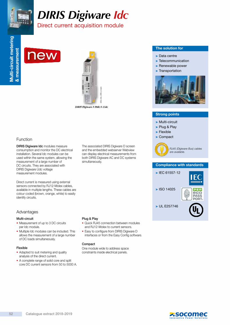
Mul
ti-ci
rcui
t m
eter
ing
&
mea
sure
men
t
Function
DIRIS Digiware Idc modules measure consumption and monitor the DC electrical installation. Several Idc modules can be used within the same system, allowing the measurement of a large number of DC circuits. They are associated with DIRIS Digiware Udc voltage measurement modules.
Direct current is measured using external sensors connected by RJ12-Molex cables, available in multiple lengths. These cables are colour coded (brown, orange, white) to easily identify circuits.
The associated DIRIS Digiware D screen and the embedded webserver Webview can display electrical measurements from both DIRIS Digiware AC and DC systems simultaneously.
> Multi-circuit > Plug & Play > Flexible > Compact
Strong points
Advantages
Multi-circuit • Measurement of up to 3 DC circuits per Idc module.
• Multiple Idc modules can be included. This allows the measurement of a large number of DC loads simultaneously.
Flexible • Adapted to suit metering and quality analysis of the direct current.
• A complete range of solid core and split core DC current sensors from 50 to 5000 A.
Plug & Play • Quick RJ45 connection between modules and RJ12-Molex to current sensors.
• Easy to configure from DIRIS Digiware D interfaces or from the Easy Config software.
CompactOne module wide to address space constraints inside electrical panels.
DIRIS Digiware I-30dc/I-35dc
> IEC 61557-12
> ISO 14025
> UL E257746
Compliance with standards
Configuration with EasyConfig,
DIRIS Digiware Idc Direct current acquisition module
RJ45 (Digiware Bus) cables are available.
RJ45Communication
new
DIRIS Digiware I-30dc/I-35dc
diris
-dw
_095
_b.e
ps
> Data centre > Telecommunication > Renewable power > Transportation
The solution for
DIRIS Digiware IdcDirect current acquisition module
Application Direct current (DC) measurement modules
DIRIS Digiware Idc I-30dc I-35dc
Number of current inputs3 3
Metering± kWh • •
Load curves •Multi-measurement
DC current (I DC) • •
DC power (P DC) • •
Predictive power •
Measurement of current qualityI ripple (current ripple) •
I rms •
AlarmsThresholds and combinations •
TrendsAverage values •
FormatWidth/number of modules 18 mm / 1
Dimensions (mm)
DIRIS Digiware Idc
diris
-dw
_106
_a_1
_cat
44 15
65
45
18
90
52 Catalogue extract 2018-2019

Mul
ti-ci
rcui
t m
eter
ing
&
mea
sure
men
t
Function
DIRIS Digiware Idc modules measure consumption and monitor the DC electrical installation. Several Idc modules can be used within the same system, allowing the measurement of a large number of DC circuits. They are associated with DIRIS Digiware Udc voltage measurement modules.
Direct current is measured using external sensors connected by RJ12-Molex cables, available in multiple lengths. These cables are colour coded (brown, orange, white) to easily identify circuits.
The associated DIRIS Digiware D screen and the embedded webserver Webview can display electrical measurements from both DIRIS Digiware AC and DC systems simultaneously.
> Multi-circuit > Plug & Play > Flexible > Compact
Strong points
Advantages
Multi-circuit • Measurement of up to 3 DC circuits per Idc module.
• Multiple Idc modules can be included. This allows the measurement of a large number of DC loads simultaneously.
Flexible • Adapted to suit metering and quality analysis of the direct current.
• A complete range of solid core and split core DC current sensors from 50 to 5000 A.
Plug & Play • Quick RJ45 connection between modules and RJ12-Molex to current sensors.
• Easy to configure from DIRIS Digiware D interfaces or from the Easy Config software.
CompactOne module wide to address space constraints inside electrical panels.
DIRIS Digiware I-30dc/I-35dc
> IEC 61557-12
> ISO 14025
> UL E257746
Compliance with standards
Configuration with EasyConfig,
DIRIS Digiware Idc Direct current acquisition module
RJ45 (Digiware Bus) cables are available.
RJ45
Communication
new
DIRIS Digiware I-30dc/I-35dc
diris
-dw
_095
_b.e
ps
> Data centre > Telecommunication > Renewable power > Transportation
The solution for
DIRIS Digiware IdcDirect current acquisition module
Application Direct current (DC) measurement modules
DIRIS Digiware Idc I-30dc I-35dc
Number of current inputs3 3
Metering± kWh • •
Load curves •Multi-measurement
DC current (I DC) • •
DC power (P DC) • •
Predictive power •
Measurement of current qualityI ripple (current ripple) •
I rms •
AlarmsThresholds and combinations •
TrendsAverage values •
FormatWidth/number of modules 18 mm / 1
Dimensions (mm)
DIRIS Digiware Idc
diris
-dw
_106
_a_1
_cat
44 15
65
45
18
90
53Catalogue extract 2018-2019

DIRIS Digiware IdcDirect current acquisition module
Connections
DIRIS Digiware U-31dcVoltage (VDC): 19 - 60 V
DIRIS Digiware U-32dc + adaptor U1000dcVoltage (VDC): 400 - 1200 V
DIRIS Digiware U-32dc + adaptor U1500dcVDC voltage: 1200 - 1500 V +10%
DIRIS Digiware U-32dcVoltage (VDC): 48 - 180 V
DIRIS Digiware U-32dc + adaptor U500dcVoltage (VDC): 200 - 600 V
I
- + NC NC
V
0 V± 19 - 60 VDC
I01 I02 I03
1 1 1
U-31
dc
I-3xd
c
I
NC NC - +
V
0 V± 48 - 180 VDC
I01 I02 I03
1 1 1
U-32
dc
I-3xd
c
I
NC NC - +
V
0 V± 200 - 600 VDC
I01 I02 I03
1 1 1
- +
- NC NC +
U-32
dc
I-3xd
c
U500
dc
I
NC NC - +
V
0 V± 400 - 1200 VDC
I01 I02 I03
1 1 1
- +
NC- NC +
U-32
dc
I-3xd
c
U100
0dc
I
NC NC - +
V
0 V± 1200 - 1500 VDC
+ 10%
I01 I02 I03
1 1 1
- +
NC- NC +
U-32
dc
I-3xd
c
U150
0dc
Network and connection examples
1. Fuse: 2A gPV 1 DC load DC current sensor
Measurement of 3 DC loads
DC current is measured by external sensors connected to the DIRIS Digiware I-3xdc modules via RJ12-Molex cables. Connection of the current sensors is quick and error-free. A wide range of current sensors is available from Socomec to suit all installations and applications including split-core current sensors for retrofit applications.
• Open-loop Hall effect sensors • Solid core or split core. • Power supply voltage: ± 15 V. • Power supply current: ± 25 mA depending on sensor. • Output voltage: ± 4 V. • 4-point male Molex terminal strip. • Measuring range: 16 to 6000 A. • Category III overvoltage.
• PIN 1: + 15 V (+ Vc) • PIN 2: - 15 V (- Vc) • PIN 3: sensor input (M) • PIN 4: 0 V sensor (0)
RJ12-Molex cable
DIRIS Digiware I-3xdc
3 DC current sensors
diris
-dw
_113
_a_1
_x_c
at.e
ps
diris
-dw
_112
_a_1
_x_c
at.e
ps
diris
-dw
_111
_a_1
_x_c
at.e
ps
diris
-dw
_110
_a_1
_x_c
at.e
ps
diris
-dw
_109
_a_1
_x_c
at.e
ps
1 2 3 4
DIRIS Digiware IdcDirect current acquisition module
Technical characteristics
Measurement characteristicsDC current measurement - DIRIS Digiware Idc
Number of current inputs 3
Associated current sensors Open-loop Hall effect
Accuracy of current measurement Class 0.5
Precision measurement of power and energy
With U-31dc/U-32dc only: class 1With U-32dc + adaptor: class 2
Connection Specific Socomec cable with RJ12-Molex connectors
Power consumption of module 2 VA
Environmental specificationsAmbient operating temperature -10 to +70°C
Storage temperature -25 to +70°C
Operating humidity 55 °C / 97% HR
Operating altitude < 2000 m
Communication specificationsUSB
Protocol Modbus RTU on USB
Function Configuration of DIRIS Digiware U and I modules
Location On each DIRIS Digiware U and I measurement module
Connection Type B micro USB connector
Digiware bus
Function Connection between DIRIS Digiware modules
Cable type Specific Socomec cable with RJ45 connections
References
DIRIS Digiware I-3xdc Part number
I-30dc Metering - 3 current inputs 4829 0156I-35dc Analysis - 3 current inputs 4829 0157RJ12-Molex cables
Number of cables
Length of cables Part number
3 0.3 m 4829 07823 0.5 m 4829 07833 1 m 4829 07843 2 m 4829 07851 5 m 4829 0786
Digiware connection cables Part number
RJ45 cables for Digiware Bus
Length 0.06 m 4829 0189Length 0.10 m 4829 0181Length 0.20 m 4829 0188Length 0.50 m 4829 0182Length 1 m 4829 0183Length 2 m 4829 0184Length 5 m 4829 0186Length 10 m 4829 018750 m reel + 100 connectors 4829 0185
Termination for Digiware Bus (supplied with interfaces C and D) 4829 0180USB configuration cable 4829 0050
Expert Services
Do you require services for your metering system?No problem for our "Expert Services" team. They will fully integrate all your Socomec devices, audit your system, commission selected equipment and train your staff on its use.For further information, please contact your nearest Socomec branch.
Mechanical featuresCasing type DIN-rail mounting module and base
Casing protection index IP20 / IK06
Front panel protection index IP40 front face in modular assembly / IK06
Weight 69 g
54 Catalogue extract 2018-2019

DIRIS Digiware IdcDirect current acquisition module
Connections
DIRIS Digiware U-31dcVoltage (VDC): 19 - 60 V
DIRIS Digiware U-32dc + adaptor U1000dcVoltage (VDC): 400 - 1200 V
DIRIS Digiware U-32dc + adaptor U1500dcVDC voltage: 1200 - 1500 V +10%
DIRIS Digiware U-32dcVoltage (VDC): 48 - 180 V
DIRIS Digiware U-32dc + adaptor U500dcVoltage (VDC): 200 - 600 V
I
- + NC NC
V
0 V± 19 - 60 VDC
I01 I02 I03
1 1 1
U-31
dc
I-3xd
c
I
NC NC - +
V
0 V± 48 - 180 VDC
I01 I02 I03
1 1 1
U-32
dc
I-3xd
c
I
NC NC - +
V
0 V± 200 - 600 VDC
I01 I02 I03
1 1 1
- +
- NC NC +
U-32
dc
I-3xd
c
U500
dc
I
NC NC - +
V
0 V± 400 - 1200 VDC
I01 I02 I03
1 1 1
- +
NC- NC +
U-32
dc
I-3xd
c
U100
0dc
I
NC NC - +
V
0 V± 1200 - 1500 VDC
+ 10%
I01 I02 I03
1 1 1
- +
NC- NC +
U-32
dc
I-3xd
c
U150
0dc
Network and connection examples
1. Fuse: 2A gPV 1 DC load DC current sensor
Measurement of 3 DC loads
DC current is measured by external sensors connected to the DIRIS Digiware I-3xdc modules via RJ12-Molex cables. Connection of the current sensors is quick and error-free. A wide range of current sensors is available from Socomec to suit all installations and applications including split-core current sensors for retrofit applications.
• Open-loop Hall effect sensors • Solid core or split core. • Power supply voltage: ± 15 V. • Power supply current: ± 25 mA depending on sensor. • Output voltage: ± 4 V. • 4-point male Molex terminal strip. • Measuring range: 16 to 6000 A. • Category III overvoltage.
• PIN 1: + 15 V (+ Vc) • PIN 2: - 15 V (- Vc) • PIN 3: sensor input (M) • PIN 4: 0 V sensor (0)
RJ12-Molex cable
DIRIS Digiware I-3xdc
3 DC current sensors
diris
-dw
_113
_a_1
_x_c
at.e
ps
diris
-dw
_112
_a_1
_x_c
at.e
ps
diris
-dw
_111
_a_1
_x_c
at.e
ps
diris
-dw
_110
_a_1
_x_c
at.e
ps
diris
-dw
_109
_a_1
_x_c
at.e
ps
1 2 3 4
DIRIS Digiware IdcDirect current acquisition module
Technical characteristics
Measurement characteristicsDC current measurement - DIRIS Digiware Idc
Number of current inputs 3
Associated current sensors Open-loop Hall effect
Accuracy of current measurement Class 0.5
Precision measurement of power and energy
With U-31dc/U-32dc only: class 1With U-32dc + adaptor: class 2
Connection Specific Socomec cable with RJ12-Molex connectors
Power consumption of module 2 VA
Environmental specificationsAmbient operating temperature -10 to +70°C
Storage temperature -25 to +70°C
Operating humidity 55 °C / 97% HR
Operating altitude < 2000 m
Communication specificationsUSB
Protocol Modbus RTU on USB
Function Configuration of DIRIS Digiware U and I modules
Location On each DIRIS Digiware U and I measurement module
Connection Type B micro USB connector
Digiware bus
Function Connection between DIRIS Digiware modules
Cable type Specific Socomec cable with RJ45 connections
References
DIRIS Digiware I-3xdc Part number
I-30dc Metering - 3 current inputs 4829 0156I-35dc Analysis - 3 current inputs 4829 0157RJ12-Molex cables
Number of cables
Length of cables Part number
3 0.3 m 4829 07823 0.5 m 4829 07833 1 m 4829 07843 2 m 4829 07851 5 m 4829 0786
Digiware connection cables Part number
RJ45 cables for Digiware Bus
Length 0.06 m 4829 0189Length 0.10 m 4829 0181Length 0.20 m 4829 0188Length 0.50 m 4829 0182Length 1 m 4829 0183Length 2 m 4829 0184Length 5 m 4829 0186Length 10 m 4829 018750 m reel + 100 connectors 4829 0185
Termination for Digiware Bus (supplied with interfaces C and D) 4829 0180USB configuration cable 4829 0050
Expert Services
Do you require services for your metering system?No problem for our "Expert Services" team. They will fully integrate all your Socomec devices, audit your system, commission selected equipment and train your staff on its use.For further information, please contact your nearest Socomec branch.
Mechanical featuresCasing type DIN-rail mounting module and base
Casing protection index IP20 / IK06
Front panel protection index IP40 front face in modular assembly / IK06
Weight 69 g
55Catalogue extract 2018-2019

Cur
rent
sen
sors
DC current sensorsAssociated with DIRIS Digiware DC
Solid-core sensors 50 … 600 A
Solid-core sensors 850 ... 5000 A
Split-core sensors 50 … 500 A
Split-core sensors 800 … 2000 A
Function
The DC current sensors measure the DC load currents of an electrical installation and transmit information to the DIRIS Digiware Idc measurement modules via an RJ12 to Molex cable on the sensor side.
The range comprises solid-core and split-core sensors ranging from 50 to 5000 A in various sizes allowing them to be used in new or existing electrical installations.Up to 3 different DC sensors can be connected to the same DIRIS Digiware Idc module.
Advantages
Plug & Play • A quick RJ12 connection makes wiring easy and reliable.
• Fast configuration of the sensor's rating.
Flexible • A complete range of solid-core and split-core sensors from 50 to 5000 A designed for new or existing electrical installations.
Installation • Easy to install. • Ideal for installations with limited space available.
• Only 4 different frame sizes cover a wide measurement range.
• Colour-coded cables for ease of identification, and to prevent wiring errors.
> Plug & Play > Wide selection of ratings > Simplified installation
Strong points
new > Data centre > Telecommunication > Renewable power > Transportation
The solution for
tore
_066
_a.e
ps
tore
_068
_a.e
ps
tore
_071
_a.e
ps
tore
_072
_a.e
ps
> IEC 61010-1
> UL
Compliance with standards
DC current sensorsAssociated with DIRIS Digiware DC
Dimensions (mm)
Solid-core sensors 50 … 600 A (frame size 1)
Split-core sensors 50 … 500 A (frame size 1)
Solid-core sensors 850 … 5000 A (frame size 2)
Split-core sensors 800 … 2000 A (frame size 2)
160
104
148
174
150
29.5 29.525.5
2 x
5.5
4 x Ø 3.3 x 10
Ø 5.5
8
2515
2340 86
50
45
20
9
tore
_091
_a_1
_x.a
i
Ø 3.2
21.5
16.5
8.25
18 18
Ø 21Ø 3.2
38
50
3
46
Ø 3.2
Ø 2.5
3
69
2.5
tore
_090
_a_1
_x.a
i
Ø 5.5
Ø 5.5
126
3715
5.7
5.5
12.8
12.5
5.5
8
144
421
2162
10864
(51.3)4643
18
12 4
tore
_092
_a_1
_x.a
i
4020.4
10.4
3
Ø 2.5
9.8
4.8
30
2.5
8.320
30
55
Ø 4.5
22.8
1610.4
tore
_093
_a_1
_x.a
i
56 Catalogue extract 2018-2019

Cur
rent
sen
sors
DC current sensorsAssociated with DIRIS Digiware DC
Solid-core sensors 50 … 600 A
Solid-core sensors 850 ... 5000 A
Split-core sensors 50 … 500 A
Split-core sensors 800 … 2000 A
Function
The DC current sensors measure the DC load currents of an electrical installation and transmit information to the DIRIS Digiware Idc measurement modules via an RJ12 to Molex cable on the sensor side.
The range comprises solid-core and split-core sensors ranging from 50 to 5000 A in various sizes allowing them to be used in new or existing electrical installations.Up to 3 different DC sensors can be connected to the same DIRIS Digiware Idc module.
Advantages
Plug & Play • A quick RJ12 connection makes wiring easy and reliable.
• Fast configuration of the sensor's rating.
Flexible • A complete range of solid-core and split-core sensors from 50 to 5000 A designed for new or existing electrical installations.
Installation • Easy to install. • Ideal for installations with limited space available.
• Only 4 different frame sizes cover a wide measurement range.
• Colour-coded cables for ease of identification, and to prevent wiring errors.
> Plug & Play > Wide selection of ratings > Simplified installation
Strong points
new > Data centre > Telecommunication > Renewable power > Transportation
The solution for
tore
_066
_a.e
ps
tore
_068
_a.e
ps
tore
_071
_a.e
ps
tore
_072
_a.e
ps
> IEC 61010-1
> UL
Compliance with standards
DC current sensorsAssociated with DIRIS Digiware DC
Dimensions (mm)
Solid-core sensors 50 … 600 A (frame size 1)
Split-core sensors 50 … 500 A (frame size 1)
Solid-core sensors 850 … 5000 A (frame size 2)
Split-core sensors 800 … 2000 A (frame size 2)
160
104
148
174
150
29.5 29.525.5
2 x
5.5
4 x Ø 3.3 x 10
Ø 5.5
8
2515
2340 86
50
45
20
9to
re_0
91_a
_1_x
.ai
Ø 3.2
21.5
16.5
8.25
18 18
Ø 21Ø 3.2
38
50
3
46
Ø 3.2
Ø 2.5
3
69
2.5
tore
_090
_a_1
_x.a
i
Ø 5.5
Ø 5.5
126
3715
5.7
5.5
12.8
12.5
5.5
8
144
421
2162
10864
(51.3)4643
18
12 4
tore
_092
_a_1
_x.a
i
4020.4
10.4
3
Ø 2.5
9.8
4.8
30
2.5
8.320
30
55
Ø 4.5
22.8
1610.4
tore
_093
_a_1
_x.a
i
57Catalogue extract 2018-2019

DC current sensorsAssociated with DIRIS Digiware DC
Connections
Technical characteristics
DC current is measured by external sensors connected to the DIRIS Digiware I-3xdc modules via RJ12-Molex cables. Connection of the current sensors is quick and error-free. A wide range of current sensors is available from Socomec to suit all installations and applications including split-core current sensors for retrofit applications. The DC current sensors have the following technical characteristics:
• Open-loop Hall effect sensors • Solid-core or split-core. • Power supply voltage: ± 15 V. • Power supply current: ± 25 mA depending on the sensor. • Output voltage: ± 4 V. • 4-point male Molex terminal strip. • Measurement range: 16 to 6000 A. • Category III overvoltage.
• PIN 1: + 15 V (+ Vc) • PIN 2: - 15 V (- Vc) • PIN 3: sensor input (M) • PIN 4: 0 V sensor (0)
RJ12-Molex cable
DIRIS Digiware I-3xdc
3 DC current sensors
1 2 3 4
Type of current sensor Open-loop Hall effect
Connection Specific Socomec cable with RJ12-Molex connectors
Accuracy of current measurement Solid-core sensors: 50 ... 600 A: < 1%Solid-core sensors: 850 ... 5000 A: < 1%Split-core sensors: 50 ... 500 A: < 2%Split-core sensors: 800 ... 2000 A: < 2%
Weight Solid-core sensors 50 … 600 A 60 g
Solid-core sensors 850 … 5000 A 450 g
Split-core sensors 50 … 500 A 80 g
Split-core sensors 800 … 2000 A 590 g
Operating temperature
Solid-core sensors 50 … 600 A -10 ... +80°C
Solid-core sensors 850 … 5000 A -25 ... +85°C
Split-core sensors 50 … 500 A -10 ... +70°C
Split-core sensors 800 … 2000 A -10 ... +70°C
Storage temperature
Solid-core sensors 50 … 600 A -25 ... +80°C
Solid-core sensors 850 … 5000 A -25 ... +85°C
Split-core sensors 50 ... 500 A -20 ... +85°C
Split-core sensors 800 … 2000 A -25 ... +85°C
DC current sensorsAssociated with DIRIS Digiware DC
References
DC current sensors Reference
Solid-core sensors (frame size 1)
50 A 4829 0700
100 A 4829 0701
200 A 4829 0702
300 A 4829 0703
400 A 4829 0704
500 A 4829 0705
600 A 4829 0706
Solid-core sensors (frame size 2)
850 A 4829 0707
1000 A 4829 0708
1500 A 4829 0709
2000 A 4829 0710
2500 A 4829 0711
5000 A 4829 0712
Split-core sensors (frame size 1)
50 A 4829 0750
100 A 4829 0751
200 A 4829 0752
300 A 4829 0753
400 A 4829 0754
500 A 4829 0755
Split-core sensors (frame size 2)
800 A 4829 0756
1000 A 4829 0757
1500 A 4829 0758
2000 A 4829 0759
RJ12-MOLEX cables
Number of cables Length of cables Reference
3 0.3 m 4829 0782
3 0.5 m 4829 0783
3 1 m 4829 0784
3 2 m 4829 0785
1 5 m 4829 0786
58 Catalogue extract 2018-2019

DC current sensorsAssociated with DIRIS Digiware DC
Connections
Technical characteristics
DC current is measured by external sensors connected to the DIRIS Digiware I-3xdc modules via RJ12-Molex cables. Connection of the current sensors is quick and error-free. A wide range of current sensors is available from Socomec to suit all installations and applications including split-core current sensors for retrofit applications. The DC current sensors have the following technical characteristics:
• Open-loop Hall effect sensors • Solid-core or split-core. • Power supply voltage: ± 15 V. • Power supply current: ± 25 mA depending on the sensor. • Output voltage: ± 4 V. • 4-point male Molex terminal strip. • Measurement range: 16 to 6000 A. • Category III overvoltage.
• PIN 1: + 15 V (+ Vc) • PIN 2: - 15 V (- Vc) • PIN 3: sensor input (M) • PIN 4: 0 V sensor (0)
RJ12-Molex cable
DIRIS Digiware I-3xdc
3 DC current sensors
1 2 3 4
Type of current sensor Open-loop Hall effect
Connection Specific Socomec cable with RJ12-Molex connectors
Accuracy of current measurement Solid-core sensors: 50 ... 600 A: < 1%Solid-core sensors: 850 ... 5000 A: < 1%Split-core sensors: 50 ... 500 A: < 2%Split-core sensors: 800 ... 2000 A: < 2%
Weight Solid-core sensors 50 … 600 A 60 g
Solid-core sensors 850 … 5000 A 450 g
Split-core sensors 50 … 500 A 80 g
Split-core sensors 800 … 2000 A 590 g
Operating temperature
Solid-core sensors 50 … 600 A -10 ... +80°C
Solid-core sensors 850 … 5000 A -25 ... +85°C
Split-core sensors 50 … 500 A -10 ... +70°C
Split-core sensors 800 … 2000 A -10 ... +70°C
Storage temperature
Solid-core sensors 50 … 600 A -25 ... +80°C
Solid-core sensors 850 … 5000 A -25 ... +85°C
Split-core sensors 50 ... 500 A -20 ... +85°C
Split-core sensors 800 … 2000 A -25 ... +85°C
DC current sensorsAssociated with DIRIS Digiware DC
References
DC current sensors Reference
Solid-core sensors (frame size 1)
50 A 4829 0700
100 A 4829 0701
200 A 4829 0702
300 A 4829 0703
400 A 4829 0704
500 A 4829 0705
600 A 4829 0706
Solid-core sensors (frame size 2)
850 A 4829 0707
1000 A 4829 0708
1500 A 4829 0709
2000 A 4829 0710
2500 A 4829 0711
5000 A 4829 0712
Split-core sensors (frame size 1)
50 A 4829 0750
100 A 4829 0751
200 A 4829 0752
300 A 4829 0753
400 A 4829 0754
500 A 4829 0755
Split-core sensors (frame size 2)
800 A 4829 0756
1000 A 4829 0757
1500 A 4829 0758
2000 A 4829 0759
RJ12-MOLEX cables
Number of cables Length of cables Reference
3 0.3 m 4829 0782
3 0.5 m 4829 0783
3 1 m 4829 0784
3 2 m 4829 0785
1 5 m 4829 0786
59Catalogue extract 2018-2019
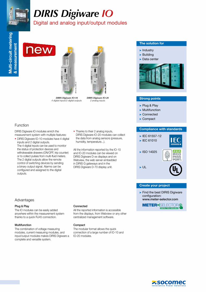
Mul
ti-ci
rcui
t m
eter
ing
&
mea
sure
men
t
Function
DIRIS Digiware IO modules enrich the measurement system with multiple features: • DIRIS Digiware IO-10 modules have 4 digital inputs and 2 digital outputs. The 4 digital inputs can be used to monitor the status of protection devices and withdrawable drawers (ON/OFF, trip counter) or to collect pulses from multi-fluid meters. The 2 digital outputs allow the remote control of switching devices by sending a binary output signal. Alarms can be configured and assigned to the digital outputs.
• Thanks to their 2 analog inputs, DIRIS Digiware IO-20 modules can collect the data from analog sensors (pressure, humidity, temperature...).
All the information reported by the IO-10 and IO-20 modules can be viewed on DIRIS Digiware D-xx displays and on Webview, the web server embedded in DIRIS G gateways and in the DIRIS Digiware D-70 display unit.
> Plug & Play > Multifunction > Connected > Compact
Strong points
Advantages
Plug & PlayThe IO modules can be easily added anywhere within the measurement system thanks to a quick RJ45 connection.
MultifunctionThe combination of voltage measuring modules, current measuring modules, and input/output modules makes DIRIS Digiware a complete and versatile system.
ConnectedAll the reported information is accessible from the displays, from Webview or any other centralized management software.
CompactThe modular format allows the quick connection of a large number of IO-10 and IO-20 modules.
> Industry > Building > Data center
The solution for
> IEC 61557-12 > IEC 61010
> ISO 14025
> UL
Compliance with standards
DIRIS Digiware IO-104 digital inputs/2 digital outputs
DIRIS Digiware IO-202 analog inputs
Configuration with EasyConfig,
DIRIS Digiware IO Digital and analog input/output modules
new
diris
-dw
_092
_b
diris
-dw
_093
_bdi
ris-d
w_0
93_b
> Find the best DIRIS Digiware configuration:www.meter-selector.com
Create your project
DIRIS Digiware IODigital and analog input/output modules
Digiware BusDigital inputs/outputs
Digiware BusAnalog inputs
DIRIS Digiware IO-10
DIRIS Digiware IO-20
Dimensions (in/mm)
References
Technical characteristics
Application diagram Connections
Digiware Bus
DIRIS Digiware D-xx
13
14
23
24
12-48VDC12-24VAC
50mA
12VDCIN1
COM-
IN2
IN3
IN4
OUT1
OUT2
OU
TPU
TIN
PU
T
DIG
IWA
RE
BU
S
RJ4
5
DIG
IWA
RE
BU
S
RJ4
50/4-20mA200 Ω max
1+
1-
2+
2-INP
UT
1.7344
0.5915
2.5665
1.77 45
0.7018
0.195
3.94
100
Digiware connection cables Reference
RJ45 cables for Digiware Bus
Length 0.10 m 4829 0181Length 0.20 m 4829 0188Length 0.50 m 4829 0182Length 1 m 4829 0183Length 2 m 4829 0184Length 5 m 4829 0186Length 10 m 4829 018750 m reel + 100 connectors 4829 0185
Termination for Digiware Bus (supplied with interfaces C and D) 4829 0180USB configuration cable 4829 0050
Measuring characteristicsDigital inputs/outputs- DIRIS Digiware IO-10
Number of inputs 4
Type/power supply Insulated input, internal polarisation 12 VDC max., 3 mA
Input function - Logical status- Status of the circuit breaker, of the drawer
(ON/OFF, trip counter)- Pulse counter
Number of outputs 2
Type Insulated output, 48 VDC max., 50 mA and 24 VAC max.
Output function - Remote control of status- Alarm signal linked to the inputs
(exceeding threshold, status...)
Input/output connection
Removable screw terminal block, 9 positions (5 dedicated to inputs, 4 dedicated to outputs)Stranded or solid 0.14 to 1.5 mm² cable
Analog inputs - DIRIS Digiware IO-20
Number of inputs 2
Type/power supply 0/4-20 mA, 200 Ω max
Accuracy 0.5% full scale
Function Connection of analog sensors (pressure, humidity, temperature...) with choice of interpolation (linear or quadratic)
Input connection Removable screw terminal block 2x2 positions,Stranded or solid 0.14 to 1.5 mm² cable
diris
-o_0
28_a
_1_c
at.a
i
diris
-g_0
22_b
_1_x
_cat
.ai
diris
-g_0
22_b
_1_x
_cat
.ai
diris
-o_0
29_a
_1_c
at.a
i
diris
-o_0
27_a
_1_c
at.a
i
DIRIS Digiware input/output modules Reference
IO-10 4 digital inputs/2 outputs module 4829 0140IO-20 2 analog input module 4829 0145
diris
-o_0
30_a
_1_c
at.a
i
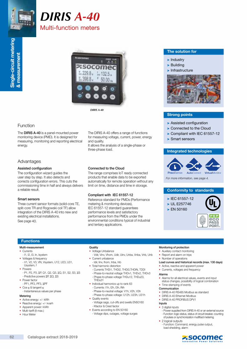
Sin
gle-
circ
uit m
eter
ing
&
mea
sure
men
tDIRIS A-40Multi-function meters
DIRIS A-40
Function
The DIRIS A-40 is a panel-mounted power monitoring device (PMD). It is designed for measuring, monitoring and reporting electrical energy.
The DIRIS A-40 offers a range of functions for measuring voltage, current, power, energy and quality. It allows the analysis of a single-phase or three-phase load.
> Assisted configuration > Connected to the Cloud > Compliant with IEC 61557-12 > Smart sensors
Strong points
AdvantagesAssisted configurationThe configuration wizard guides the user step by step. It also detects and corrects configuration errors. This cuts the commissioning time in half and always delivers a reliable result.
Smart sensorsThree current sensor formats (solid-core TE, split-core TR and Rogowski coil TF) allow integration of the DIRIS A-40 into new and existing electrical installations.See page
Connected to the CloudThe range comprises IoT ready connected products that enable data to be exported automatically for remote operation without any limit on time, distance and time in storage.
Compliant with IEC 61557-12Reference standard for PMDs (Performance metering & monitoring devices), IEC 61557-12 standard guarantees performance levels and satisfactory performance from the PMDs under the environmental conditions typical of industrial and tertiary applications.
> Industry > Building > Infrastructure
The solution for
> IEC 61557-12 > UL E257746 > EN 50160
Conformity to standards
Multi-measurement • Currents
- I1, I2, I3, In, Isystem • Voltages & frequency
- V1, V2, V3, VN, Vsystem, U12, U23, U31, Usystem, f
• Powers- P1, P2, P3, ΣP, Q1, Q2, Q3, ΣQ, S1, S2, S3, ΣS- Predictive powers ΣP, ΣQ, ΣS
• Power factor- PF1, PF2, PF3, ΣPF
• Cos ϕ & tangent ϕ- Instantaneous values per phase
Metering • Active energy: +/- kWh • Reactive energy: +/- kvarh • Apparent power: kVAh • Multi-tariff (8 max.) • Hour Meter
Quality • Voltage Unbalance
- Vdir, Vinv, Vhom, Udir, Uinv, Unba, Vnba, Vnb, Unb • Current unbalance
- Idir, Iinv, Ihom, Inba, Inb • Total harmonic distortion
- Currents THDi1, THDi2, THDi3,THDiN, TDDI- Phase-to-neutral voltage THDv1, THDv2, THDv3- Phase-to-phase voltage THDu12, THDu23,
THDu31 • Individual harmonics up to rank 63
- Currents: I1h, I2h, I3h, INh- Phase-to-neutral voltage: V1h, V2h, V3h- Phase-to-phase voltage: U12h, U23h, U31h
• Quality events- Voltage sags, cut-offs and swells EN50160 - Kfactor & Crest factor
• Events according to EN 50160- Voltage dips, outages, voltage surges
Monitoring of protection • Auxiliary contact monitoring • Report and alarm on trips • Number of operations
Load curves and historical records (max. 130 days) • Active, reactive and apparent power • Currents, voltages and frequency
Alarms • Alarms for all electrical values, events and input
status changes, possibility of logical combination • Time-stamping of events
Communication • DIRIS A-40 RS485 Modbus as standard • DIRIS A-40 Ethernet Modbus • DIRIS A-40 PROFIBUS DPV1
Inputs • 3 digital inputs
- Power supplied from DIRIS A-40 or an external source- Function: logic status, status of circuit breaker, counting
of pulses or synchronization multifluid metering • 2 logical outputs- Function: Command, energy pulse output,
load shedding, alarm
Functions
Integrated technologies
For more information, see page
DIRIS A-40Multi-functions meters
Dimensions (mm)
98
92 68 17
9892
3 inputs supplied by the product
3 inputs with external power supply 2 outputs Earth
Current measurement
NCSla
veR
S48
5
LIYC
Y-CYI 01
RS485Voltage connections inc auxiliary power supply
1. 0.5 A gG / 0.5 A class CC fuses.
110-230VACN
L1
L2
L3
V2 V3 VNV1
NL
111
INPUT
OUTPUT
Monitoring • Real-time measurement of electrical values. • View data as graphs or tables. • Power quality analysis of the utility supply and of loads.
Metering • Measurement of active, reactive and apparent energies.
• Historical record of measurements. • Graphic display on monthly, weekly, daily or hourly basis.
Alarming • Display of alarms. • History of alarms.
Functions
Terminals
diris
_977
_a.a
i
RJ12
I 03I 02I 01
diris_
969_
a_1_
x_ca
t.ai
diris-b_024_b_1_x_cat.ai
123
IN
10-30 VDC
diris
_972
_a_1
_x_c
at.a
i
123
IN
12 VDC
diris
_971
_a_1
_x_c
at.a
i
USB
RS485
Auxiliary power supply
Voltage measurement
3 digital inputs
Ethernet
Profibus
2 digital outputs
Current measurement
diris
_968
_a_1
_en_
cat.a
i
diris
_967
_a_1
_x_c
at.a
i
soft_025_a_1_fr_cat.eps
soft_036_a_1_fr_cat.eps
soft_027_a_1_fr_cat.eps
40.
62 Catalogue extract 2018-201962 Catalogue extract 2018-2019
4.
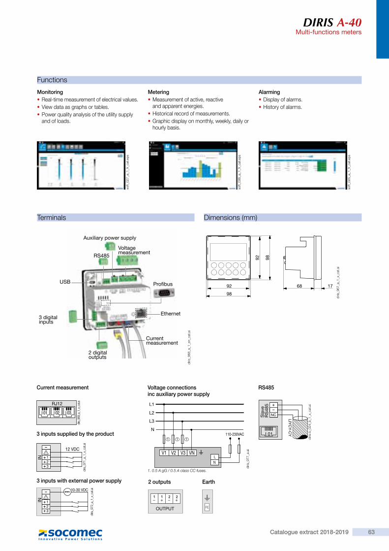
Sin
gle-
circ
uit m
eter
ing
&
mea
sure
men
t
DIRIS A-40Multi-function meters
DIRIS A-40
Function
The DIRIS A-40 is a panel-mounted power monitoring device (PMD). It is designed for measuring, monitoring and reporting electrical energy.
The DIRIS A-40 offers a range of functions for measuring voltage, current, power, energy and quality. It allows the analysis of a single-phase or three-phase load.
> Assisted configuration > Connected to the Cloud > Compliant with IEC 61557-12 > Smart sensors
Strong points
AdvantagesAssisted configurationThe configuration wizard guides the user step by step. It also detects and corrects configuration errors. This cuts the commissioning time in half and always delivers a reliable result.
Smart sensorsThree current sensor formats (solid-core TE, split-core TR and Rogowski coil TF) allow integration of the DIRIS A-40 into new and existing electrical installations.See page
Connected to the CloudThe range comprises IoT ready connected products that enable data to be exported automatically for remote operation without any limit on time, distance and time in storage.
Compliant with IEC 61557-12Reference standard for PMDs (Performance metering & monitoring devices), IEC 61557-12 standard guarantees performance levels and satisfactory performance from the PMDs under the environmental conditions typical of industrial and tertiary applications.
> Industry > Building > Infrastructure
The solution for
> IEC 61557-12 > UL E257746 > EN 50160
Conformity to standards
Multi-measurement • Currents
- I1, I2, I3, In, Isystem • Voltages & frequency
- V1, V2, V3, VN, Vsystem, U12, U23, U31, Usystem, f
• Powers- P1, P2, P3, ΣP, Q1, Q2, Q3, ΣQ, S1, S2, S3, ΣS- Predictive powers ΣP, ΣQ, ΣS
• Power factor- PF1, PF2, PF3, ΣPF
• Cos ϕ & tangent ϕ- Instantaneous values per phase
Metering • Active energy: +/- kWh • Reactive energy: +/- kvarh • Apparent power: kVAh • Multi-tariff (8 max.) • Hour Meter
Quality • Voltage Unbalance
- Vdir, Vinv, Vhom, Udir, Uinv, Unba, Vnba, Vnb, Unb • Current unbalance
- Idir, Iinv, Ihom, Inba, Inb • Total harmonic distortion
- Currents THDi1, THDi2, THDi3,THDiN, TDDI- Phase-to-neutral voltage THDv1, THDv2, THDv3- Phase-to-phase voltage THDu12, THDu23,
THDu31 • Individual harmonics up to rank 63
- Currents: I1h, I2h, I3h, INh- Phase-to-neutral voltage: V1h, V2h, V3h- Phase-to-phase voltage: U12h, U23h, U31h
• Quality events- Voltage sags, cut-offs and swells EN50160 - Kfactor & Crest factor
• Events according to EN 50160- Voltage dips, outages, voltage surges
Monitoring of protection • Auxiliary contact monitoring • Report and alarm on trips • Number of operations
Load curves and historical records (max. 130 days) • Active, reactive and apparent power • Currents, voltages and frequency
Alarms • Alarms for all electrical values, events and input
status changes, possibility of logical combination • Time-stamping of events
Communication • DIRIS A-40 RS485 Modbus as standard • DIRIS A-40 Ethernet Modbus • DIRIS A-40 PROFIBUS DPV1
Inputs • 3 digital inputs
- Power supplied from DIRIS A-40 or an external source- Function: logic status, status of circuit breaker, counting
of pulses or synchronization multifluid metering • 2 logical outputs- Function: Command, energy pulse output,
load shedding, alarm
Functions
Integrated technologies
For more information, see page
DIRIS A-40Multi-functions meters
Dimensions (mm)
98
92 68 17
9892
3 inputs supplied by the product
3 inputs with external power supply 2 outputs Earth
Current measurement
NCSla
veR
S48
5
LIYC
Y-CYI 01
RS485Voltage connections inc auxiliary power supply
1. 0.5 A gG / 0.5 A class CC fuses.
110-230VACN
L1
L2
L3
V2 V3 VNV1
NL
111
INPUT
OUTPUT
Monitoring • Real-time measurement of electrical values. • View data as graphs or tables. • Power quality analysis of the utility supply and of loads.
Metering • Measurement of active, reactive and apparent energies.
• Historical record of measurements. • Graphic display on monthly, weekly, daily or hourly basis.
Alarming • Display of alarms. • History of alarms.
Functions
Terminals
diris
_977
_a.a
i
RJ12
I 03I 02I 01
diris_
969_
a_1_
x_ca
t.ai
diris-b_024_b_1_x_cat.ai
123
IN
10-30 VDC
diris
_972
_a_1
_x_c
at.a
i
123
IN
12 VDC
diris
_971
_a_1
_x_c
at.a
i
USB
RS485
Auxiliary power supply
Voltage measurement
3 digital inputs
Ethernet
Profibus
2 digital outputs
Current measurement
diris
_968
_a_1
_en_
cat.a
i
diris
_967
_a_1
_x_c
at.a
i
soft_025_a_1_fr_cat.eps
soft_036_a_1_fr_cat.eps
soft_027_a_1_fr_cat.eps
63Catalogue extract 2018-2019 63Catalogue extract 2018-2019
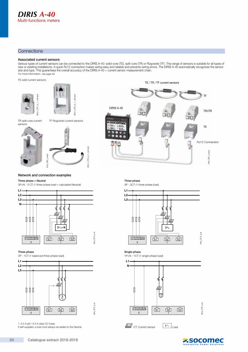
DIRIS A-40Multi-functions meters
Connections
Associated current sensorsVarious types of current sensors can be connected to the DIRIS A-40: solid-core (TE), split-core (TR) or Rogowski (TF). This range of sensors is suitable for all types of new or existing installations. A quick RJ12 connection makes wiring easy and reliable and prevents wiring errors. The DIRIS A-40 automatically recognizes the sensor size and type. This guarantees the overall accuracy of the DIRIS A-40 + current sensor measurement chain.For more information:
TE solid current sensors
Three phase + Neutral3P+N - 3 CT (1 three-phase load + calculated Neutral)
Three-phase3P - 1CT (1 balanced three-phase load)
Single-phase1P+N - 1CT (1 single-phase load)
N
V1 V2 V3 VNV I
L1
L2
L3
I01 I02 I03
3 + N
V1 V2 V3 VNV I
L1
L2
L3
3
I01 I02 I03 V1 V2 V3 VNV I
L1
N
I02 I03
1
I01
Network and connection examples
1. 0.5 A gG / 0.5 A class CC fuses.If self-supplied, a fuse must always be added to the Neutral. 3 Load CT: Current sensor
TR split-core current sensors
TF Rogowski current sensors
Three-phase3P - 3CT (1 three-phase load)
V1 V2 V3 VNV I
L1
L2
L3
I01 I02 I03
3
DIRIS A-40
TE / TR / TF current sensors
TR/iTR
TF
TE
RJ12 Connection
diris
_974
_a.a
idi
ris_9
76_a
.ai
diris
_975
_a.a
idi
ris_9
73_a
.ai
diris
_991
_a.e
ps
diris
-t_0
16_a
_1_c
at.e
ps
tore
_082
_a.e
ps
diris
-t_0
03_a
_1_c
at.e
ps
diris
-t_0
01_a
_1_c
at.e
ps
DIRIS A-40Multi-functions meters
References
DIRIS A-40 monitoring devices ReferenceDIRIS A-40 RS485 Modbus - 3 inputs / 2 outputs 4825 0500DIRIS A-40 Ethernet Modbus TCP and webserver - RS485 Modbus - 3 inputs / 2 outputs 4825 0501DIRIS A-40 Profibus DPV1 - RS485 Modbus - 3 inputs / 2 outputs 4825 0502
DIRIS A-40 characteristics
Current measurement
Number of current inputs 3
Associated current sensors Solid TE, split-core TR, flexible TF current sensors
Accuracy 0.2 DIRIS A-40 class only Class 0.5 with TE, TF or iTR sensorsClass 1 with TR sensors
Connection Specific Socomec cable with RJ12 connectors
Voltage measurement
Characteristics of the network measured
50-300VAC (Ph/N) - 87-520VAC (Ph/Ph) - CAT III
Frequency range 45 to 65Hz
Frequency accuracy Class 0.02
Network type Single-phase/ Two-phase / Two-phase with neutral / Three-phase / Three-phase with neutral
Measurement by voltage transformer Primary: 400 000 VACSecondary: 60, 100, 110, 173, 190 VAC
Input consumption ≤ 0,1 VA
Accuracy of voltage measurement Class 0.2
Connection Removable spring-cage terminal block, 4 positions, 0.5 - 2.5 mm² solid cable or 0.25 - 1.5 mm² stranded cable with end piece
Measurement characteristicsPower and energy measurement
AccuracyActive energy and active power
0.2 DIRIS A-40 class only Class 0.5 with TE, TF or iTR sensorsClass 1 with TR sensors
Accuracy of reactive energy Class 2 with TE, TR or TF sensors
Electrical characteristicsAuxiliary power supply
Alternative voltage 110/400 VAC or 120/300 VDC - Cat III
Frequency 50/60 Hz
Power consumption
5VA AC / 1,5VA DC (48250500)8VA AC / 2,5VA DC (48250501 & 48250502)
Connection Removable spring-cage terminal block, 2x 2 positions, 0.5 - 2.5 mm² solid cable or 0.25 - 1.5 mm² stranded cable with end piece
Input characteristicsNumber 3
Type / Power supply
Optocoupler with internal (12 VDC ± 10%) or external (12-24 VDC ± 20%) polarisation
Input function Logic status, status of circuit breaker, synchronization topography, multifluid pulse metering
Connection Removable screw terminal block, 5 positions, stranded or solid 0.14 - 1.5 mm² cable
Output characteristicsNumber 2
Type Optocoupler 30 Vd.c. max 20mA max - SELV
Output function Command, energy pulse output, load shedding, alarm
Connection Removable screw terminal block, 4 positions, stranded or solid 0.14 - 1.5 mm² cable
Communication characteristicsDIRIS A-40 RS485
Link RS485
Connection type 2 to 3 half duplex wires
Protocol Modbus RTU
Baud rate 1200 to 115 200 baud
USB Configuration of DIRIS A-40
Power factor measurement
Accuracy Class 0.5 with TE, TF or iTR sensorsClass 1 with TR sensors
64 Catalogue extract 2018-201964 Catalogue extract 2018-2019
see page 40.

DIRIS A-40Multi-functions meters
Connections
Associated current sensorsVarious types of current sensors can be connected to the DIRIS A-40: solid-core (TE), split-core (TR) or Rogowski (TF). This range of sensors is suitable for all types of new or existing installations. A quick RJ12 connection makes wiring easy and reliable and prevents wiring errors. The DIRIS A-40 automatically recognizes the sensor size and type. This guarantees the overall accuracy of the DIRIS A-40 + current sensor measurement chain.For more information:
TE solid current sensors
Three phase + Neutral3P+N - 3 CT (1 three-phase load + calculated Neutral)
Three-phase3P - 1CT (1 balanced three-phase load)
Single-phase1P+N - 1CT (1 single-phase load)
N
V1 V2 V3 VNV I
L1
L2
L3
I01 I02 I03
3 + N
V1 V2 V3 VNV I
L1
L2
L3
3
I01 I02 I03 V1 V2 V3 VNV I
L1
N
I02 I03
1
I01
Network and connection examples
1. 0.5 A gG / 0.5 A class CC fuses.If self-supplied, a fuse must always be added to the Neutral. 3 Load CT: Current sensor
TR split-core current sensors
TF Rogowski current sensors
Three-phase3P - 3CT (1 three-phase load)
V1 V2 V3 VNV I
L1
L2
L3
I01 I02 I03
3
DIRIS A-40
TE / TR / TF current sensors
TR/iTR
TF
TE
RJ12 Connection
diris
_974
_a.a
idi
ris_9
76_a
.ai
diris
_975
_a.a
idi
ris_9
73_a
.ai
diris
_991
_a.e
ps
diris
-t_0
16_a
_1_c
at.e
ps
tore
_082
_a.e
ps
diris
-t_0
03_a
_1_c
at.e
ps
diris
-t_0
01_a
_1_c
at.e
ps
DIRIS A-40Multi-functions meters
References
DIRIS A-40 monitoring devices ReferenceDIRIS A-40 RS485 Modbus - 3 inputs / 2 outputs 4825 0500DIRIS A-40 Ethernet Modbus TCP and webserver - RS485 Modbus - 3 inputs / 2 outputs 4825 0501DIRIS A-40 Profibus DPV1 - RS485 Modbus - 3 inputs / 2 outputs 4825 0502
DIRIS A-40 characteristics
Current measurement
Number of current inputs 3
Associated current sensors Solid TE, split-core TR, flexible TF current sensors
Accuracy 0.2 DIRIS A-40 class only Class 0.5 with TE, TF or iTR sensorsClass 1 with TR sensors
Connection Specific Socomec cable with RJ12 connectors
Voltage measurement
Characteristics of the network measured
50-300VAC (Ph/N) - 87-520VAC (Ph/Ph) - CAT III
Frequency range 45 to 65Hz
Frequency accuracy Class 0.02
Network type Single-phase/ Two-phase / Two-phase with neutral / Three-phase / Three-phase with neutral
Measurement by voltage transformer Primary: 400 000 VACSecondary: 60, 100, 110, 173, 190 VAC
Input consumption ≤ 0,1 VA
Accuracy of voltage measurement Class 0.2
Connection Removable spring-cage terminal block, 4 positions, 0.5 - 2.5 mm² solid cable or 0.25 - 1.5 mm² stranded cable with end piece
Measurement characteristicsPower and energy measurement
AccuracyActive energy and active power
0.2 DIRIS A-40 class only Class 0.5 with TE, TF or iTR sensorsClass 1 with TR sensors
Accuracy of reactive energy Class 2 with TE, TR or TF sensors
Electrical characteristicsAuxiliary power supply
Alternative voltage 110/400 VAC or 120/300 VDC - Cat III
Frequency 50/60 Hz
Power consumption
5VA AC / 1,5VA DC (48250500)8VA AC / 2,5VA DC (48250501 & 48250502)
Connection Removable spring-cage terminal block, 2x 2 positions, 0.5 - 2.5 mm² solid cable or 0.25 - 1.5 mm² stranded cable with end piece
Input characteristicsNumber 3
Type / Power supply
Optocoupler with internal (12 VDC ± 10%) or external (12-24 VDC ± 20%) polarisation
Input function Logic status, status of circuit breaker, synchronization topography, multifluid pulse metering
Connection Removable screw terminal block, 5 positions, stranded or solid 0.14 - 1.5 mm² cable
Output characteristicsNumber 2
Type Optocoupler 30 Vd.c. max 20mA max - SELV
Output function Command, energy pulse output, load shedding, alarm
Connection Removable screw terminal block, 4 positions, stranded or solid 0.14 - 1.5 mm² cable
Communication characteristicsDIRIS A-40 RS485
Link RS485
Connection type 2 to 3 half duplex wires
Protocol Modbus RTU
Baud rate 1200 to 115 200 baud
USB Configuration of DIRIS A-40
Power factor measurement
Accuracy Class 0.5 with TE, TF or iTR sensorsClass 1 with TR sensors
65Catalogue extract 2018-2019 65Catalogue extract 2018-2019

Sing
le-c
ircui
t met
erin
g,
mea
sure
men
t &
an
alys
isDIRIS A-30/A-41Multifunction performance metering & monitoring device - PMDEnergy monitoring
Functions
Multi-measurement • Currents- instantaneous: I1, I2, I3, In, Isystem- average/max average: I1, I2, I3, In
• Voltages & frequency- instantaneous: V1, V2, V3, U12,
U23, U31, F, Vsystem, Usystem- average/max average: V1, V2, V3,
U12, U23, U31, F • Powers- instantaneous: 3P, ΣP, 3Q, ΣQ,
3S, ΣS- max average: ΣP, ΣQ, ΣS- predictive: (ΣP), (ΣQ), (ΣS)
• Power factors- instantaneous: 3PF, ΣPF- average/max average: ΣPF
• Kfactor • Temperatures (1)
- internal- external via 3 PT100 probes
Metering • Active energy: +/- kWh • Reactive energy: +/- kvarh • Effective power: kVAh • Timetable:
Harmonic analysis • Level of harmonic distortion
- Currents: thd I1, thd I2, thd I3, thd In- Phase-to-neutral voltage: thd V1, thd
V2, thd V3 Phase-to-phase voltage: thd U12, thd U23, thd U31
• Individual readings up to 63rd level- Currents: HI1, HI2, HI3, HIn- Phase-to-neutral voltage:
HV1, HV2, HV3,- Phase-to-phase voltages:
HU12, HU23, HU31Load curve (1)
• Active & reactive power: ΣP+/- ; ΣQ+/-
• Voltages & frequency: V1, V2, V3, U12, U23, U31, F
Events (1)
• Alarms on all electrical parameters.
Communications (1)
• RS485 (Modbus & Profibus-DP) • Ethernet (Modbus/TCP or Modbus RTU over TCP and Web server)
• Ethernet with RS485 Modbus RTU gateway over TCP
Inputs/ Outputs(1)
• Pulse counting • Checking / control of equipment items
• Alarm report • Pulse report
Analogue output • Analogue 0/4- 20 mA
(1) Available as an option(see following pages).
diris
_581
_h_1
_en_
cat
Advantages
User-friendly operationWith its large backlit multiple-display screen with 6 hot keys, the DIRIS A-30 is easy to use.Detects wiring errors. The DIRIS A-30 is provided with a correction function for TC wiring errors.CustomisableThe DIRIS A-30 can be equipped with additional modules that give the user flexibility throughout the service life of the product. Communication modules and additional digital or analogue inputs/outputs can be used to increase its range of functionality.
Compliant with IEC 61557-12Reference standard for PMDs (Performance metering & monitoring devices), IEC 61557-12 guarantees performance levels and satisfactory performance from the PMDs under the environmental conditions typical of industrial and tertiary applications.
DIRIS A-30
FunctionThe DIRIS A-30 and A-41 are performance metering & monitoring devices that provide the user with all of the measurements needed to complete energy efficiency projects and to assure the monitoring of electrical distribution.All the information can be used and analysed remotely using energy efficiency software packages.
> Industry > Building > Infrastructures
The solution for
> User-friendly operation > Detects wiring errors. > Customisable > Web server function > Compliant with IEC 61557-12
Strong points
Functional diagram
RS485
DIRIS A-30 DIRIS A-30 DIRIS A-30
Eth
erne
t
Energy efficiency software
PLC
DIRIS A-41
WEBVIEW
> IEC 61557-12 > IEC 62053-22 class 0.5 S
> IEC 62053-23 class 2
> UL
Compliance with standards
diris
_984
_a_f
ront
.eps
DIRIS A-30/A-41Multifunction performance metering & monitoring device - PMD
Energy monitoring
Integratable modules
diris
_773
_a
DIRIS® A-30
diris
_774
_a
DIRIS® A-41*
diris
_445
_a_1
_cat
2 configurable pulse outputs (type, weight and run) on ±kWh, ±kvarh and kVAh.
Pulse outputs
diris
_447
_a_1
_cat
RS485 link with MODBUS® protocol (speed up to 38400 baud).
MODBUS® communication
diris
_448
_a_1
_cat You can connect a maximum of 2 modules, i.e. 4 analogue outputs.
2 outputs can be allocated to:3I, In, 3V, 3U, F, ±ΣP, ±ΣQ, ΣS, ΣPFL/C, I sys, Vsys, Usys, Ppred, Q pred, Spred, T°C internal, T°C 1, T°C 2, T°C3 and to 30 VDC power supply.
Analogue outputs
diris
_449
_a_1
_cat
You can connect a maximum of 3 modules, i.e. 6 inputs / 6 outputs.2 outputs can be allocated to:- monitoring: 3I, In, 3V, 3U, F, ±ΣP, ±ΣQ, ΣS, ΣPFL/C, THD 3I, THD In, THD 3V, THD
3U, Ppred, Qpred, Spred, T°C internal, T°C 1, T°C2, T°C3 and of time counter,- remote control,- timed remote control,- 2 inputs for pulse counting.
2 inputs - 2 outputs
diris
_682
_a_1
_cat • Memory function up to max. 62 days for P+, P-, Q+, Q- with a TOP for internal or
external synchronisation of 5, 8, 10, 15, 20, 30 and 60 minutes. • Memory function for the last 10 timed and dated alarms. • Memory function for the last min and max instantaneous values for 3U, 3V, 3I, In, F, ΣP±, ΣQ±, ΣS, THD 3U, THD 3V, THD, 3U, THD, 3V, THD, 3I, THD In.
• Memory function of average values 3U, 3V et F as a function of synchronisation (maximum 60 days).
Storage capability
1 2 3 4 5 6 7diris
_984
x_a_
1_ca
t
1. Backlit LCD display2. Pushbutton for currents and for connection correction function3. Pushbutton for voltages and frequency..4. Pushbutton for active, reactive and effective powers and for power factor.5. Pushbutton for maximum and average values for currents and power levels.6. Pushbutton for harmonics.7. Pushbutton for electrical energy meters, timers and impulse counters
Front panel
* With current measurement module for Neutral as standard.
• Ethernet link with MODBUS/TCP or MODBUS RTU over TCP. • Connect 1 to 247 RS485 MODBUS slaves. • Integrated webserver function (1).
Ethernet communication with RS485 MODBUS gateway
diris
_776
_a_1
_cat
diris
_777
_a_1
_cat Ethernet communication
• Ethernet link with MODBUS/TCP or MODBUS RTU over TCP. • Integrated web server function (1).
66 Catalogue extract 2018-201966 Catalogue extract 2018-2019
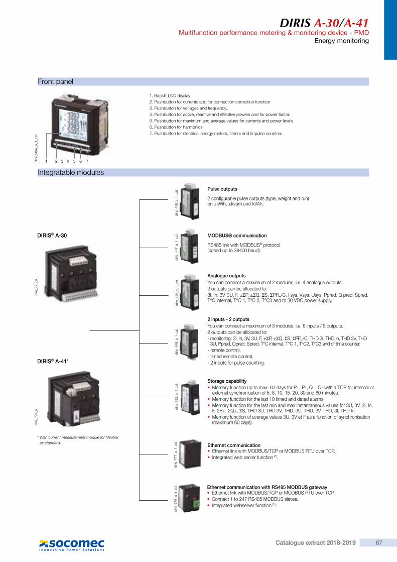
Sing
le-c
ircui
t met
erin
g,
mea
sure
men
t &
an
alys
is
DIRIS A-30/A-41Multifunction performance metering & monitoring device - PMDEnergy monitoring
Functions
Multi-measurement • Currents- instantaneous: I1, I2, I3, In, Isystem- average/max average: I1, I2, I3, In
• Voltages & frequency- instantaneous: V1, V2, V3, U12,
U23, U31, F, Vsystem, Usystem- average/max average: V1, V2, V3,
U12, U23, U31, F • Powers- instantaneous: 3P, ΣP, 3Q, ΣQ,
3S, ΣS- max average: ΣP, ΣQ, ΣS- predictive: (ΣP), (ΣQ), (ΣS)
• Power factors- instantaneous: 3PF, ΣPF- average/max average: ΣPF
• Kfactor • Temperatures (1)
- internal- external via 3 PT100 probes
Metering • Active energy: +/- kWh • Reactive energy: +/- kvarh • Effective power: kVAh • Timetable:
Harmonic analysis • Level of harmonic distortion
- Currents: thd I1, thd I2, thd I3, thd In- Phase-to-neutral voltage: thd V1, thd
V2, thd V3 Phase-to-phase voltage: thd U12, thd U23, thd U31
• Individual readings up to 63rd level- Currents: HI1, HI2, HI3, HIn- Phase-to-neutral voltage:
HV1, HV2, HV3,- Phase-to-phase voltages:
HU12, HU23, HU31Load curve (1)
• Active & reactive power: ΣP+/- ; ΣQ+/-
• Voltages & frequency: V1, V2, V3, U12, U23, U31, F
Events (1)
• Alarms on all electrical parameters.
Communications (1)
• RS485 (Modbus & Profibus-DP) • Ethernet (Modbus/TCP or Modbus RTU over TCP and Web server)
• Ethernet with RS485 Modbus RTU gateway over TCP
Inputs/ Outputs(1)
• Pulse counting • Checking / control of equipment items
• Alarm report • Pulse report
Analogue output • Analogue 0/4- 20 mA
(1) Available as an option(see following pages).
diris
_581
_h_1
_en_
cat
Advantages
User-friendly operationWith its large backlit multiple-display screen with 6 hot keys, the DIRIS A-30 is easy to use.Detects wiring errors. The DIRIS A-30 is provided with a correction function for TC wiring errors.CustomisableThe DIRIS A-30 can be equipped with additional modules that give the user flexibility throughout the service life of the product. Communication modules and additional digital or analogue inputs/outputs can be used to increase its range of functionality.
Compliant with IEC 61557-12Reference standard for PMDs (Performance metering & monitoring devices), IEC 61557-12 guarantees performance levels and satisfactory performance from the PMDs under the environmental conditions typical of industrial and tertiary applications.
DIRIS A-30
FunctionThe DIRIS A-30 and A-41 are performance metering & monitoring devices that provide the user with all of the measurements needed to complete energy efficiency projects and to assure the monitoring of electrical distribution.All the information can be used and analysed remotely using energy efficiency software packages.
> Industry > Building > Infrastructures
The solution for
> User-friendly operation > Detects wiring errors. > Customisable > Web server function > Compliant with IEC 61557-12
Strong points
Functional diagram
RS485
DIRIS A-30 DIRIS A-30 DIRIS A-30
Eth
erne
t
Energy efficiency software
PLC
DIRIS A-41
WEBVIEW
> IEC 61557-12 > IEC 62053-22 class 0.5 S
> IEC 62053-23 class 2
> UL
Compliance with standards
diris
_984
_a_f
ront
.eps
DIRIS A-30/A-41Multifunction performance metering & monitoring device - PMD
Energy monitoring
Integratable modules
diris
_773
_a
DIRIS® A-30
diris
_774
_a
DIRIS® A-41*
diris
_445
_a_1
_cat
2 configurable pulse outputs (type, weight and run) on ±kWh, ±kvarh and kVAh.
Pulse outputs
diris
_447
_a_1
_cat
RS485 link with MODBUS® protocol (speed up to 38400 baud).
MODBUS® communication
diris
_448
_a_1
_cat You can connect a maximum of 2 modules, i.e. 4 analogue outputs.
2 outputs can be allocated to:3I, In, 3V, 3U, F, ±ΣP, ±ΣQ, ΣS, ΣPFL/C, I sys, Vsys, Usys, Ppred, Q pred, Spred, T°C internal, T°C 1, T°C 2, T°C3 and to 30 VDC power supply.
Analogue outputs
diris
_449
_a_1
_cat
You can connect a maximum of 3 modules, i.e. 6 inputs / 6 outputs.2 outputs can be allocated to:- monitoring: 3I, In, 3V, 3U, F, ±ΣP, ±ΣQ, ΣS, ΣPFL/C, THD 3I, THD In, THD 3V, THD
3U, Ppred, Qpred, Spred, T°C internal, T°C 1, T°C2, T°C3 and of time counter,- remote control,- timed remote control,- 2 inputs for pulse counting.
2 inputs - 2 outputs
diris
_682
_a_1
_cat • Memory function up to max. 62 days for P+, P-, Q+, Q- with a TOP for internal or
external synchronisation of 5, 8, 10, 15, 20, 30 and 60 minutes. • Memory function for the last 10 timed and dated alarms. • Memory function for the last min and max instantaneous values for 3U, 3V, 3I, In, F, ΣP±, ΣQ±, ΣS, THD 3U, THD 3V, THD, 3U, THD, 3V, THD, 3I, THD In.
• Memory function of average values 3U, 3V et F as a function of synchronisation (maximum 60 days).
Storage capability
1 2 3 4 5 6 7diris
_984
x_a_
1_ca
t
1. Backlit LCD display2. Pushbutton for currents and for connection correction function3. Pushbutton for voltages and frequency..4. Pushbutton for active, reactive and effective powers and for power factor.5. Pushbutton for maximum and average values for currents and power levels.6. Pushbutton for harmonics.7. Pushbutton for electrical energy meters, timers and impulse counters
Front panel
* With current measurement module for Neutral as standard.
• Ethernet link with MODBUS/TCP or MODBUS RTU over TCP. • Connect 1 to 247 RS485 MODBUS slaves. • Integrated webserver function (1).
Ethernet communication with RS485 MODBUS gateway
diris
_776
_a_1
_cat
diris
_777
_a_1
_cat Ethernet communication
• Ethernet link with MODBUS/TCP or MODBUS RTU over TCP. • Integrated web server function (1).
67Catalogue extract 2018-2019 67Catalogue extract 2018-2019

DIRIS A-30/A-41Multifunction performance metering & monitoring device - PMDEnergy monitoring
Accessories
traf
o_02
4_a_
2_ca
t
Current transformer (see page
traf
o_07
7_b_
2_ca
t
diris
_720
_a_2
_cat
IP65 protection.
Terminals
DIRIS A-30
A U XV3 VNV1 V2
I3I2I1
S2S1 S2S1 S2S1
diris
_569
_a_1
_x_c
at
S1 - S2 : current inputs
AUX : auxiliary power supplies Us
V1- V2 - V3 - VN : voltage inputs
DIRIS A-30
0 V - +
R = 120 RS4850n
1
DIRIS A-30 / A-41diris
_571
_a_1
_x_c
at
RS485 link.R = 120 Ω : internal resistance for the RS485 link.
5 6 7 8
DIRIS A-30 / A-41
0/4-20 mAOUT 1
0/4-20 mAOUT 2
-+ -+
diris
_573
_a_1
_x_c
at
5 - 6 : analogue output n°1.7 - 8 : analogue output n°2.
1 2 3 4
DIRIS A-30 / A-41OUT 1 OUT 2
diris
_572
_a_1
_x_c
at
1 - 2 : pulse output n°1.3 - 4 : relay output n°2.
9 10 11 12
DIRIS A-30 / A-41IN 1
OUT 2A-Cd
OUT 1A-Cd
1 3 14 15 16
IN 2- + - +
diris
_574
_b_1
_x_c
at
9 - 10 : relay output n°1.11 - 12 : relay output n°2.13 - 14 : optical input n°1.15 - 16 : optical input n°2.
17 18
DIRIS A-30 / A-41
INsynchro
-+
diris
_683
_a_1
_x_c
at
17 - 18 : synchronisation input.
DIRIS A-30 / A-41
10 BASE T100 BASE T
RJ45
diris
_752
_a_1
_x_c
at
DIRIS A-41
A U XV3 VNV1 V2
I3I2I1
S2S1 S2S1 S2S1
IN
S2S1
diris
_570
_a_1
_x_c
at
S1 - S2 : current inputs
AUX: auxiliary power supplies Us
V1 - V2 - V3 - VN : voltage inputs
DIRIS A-41
DIRIS A-30 / A-41
22 23 24 262519 20 21
27 28 29 30
sonde 1 sonde 2
sonde 3diris
_753
_a_1
_fr_
cat
DIRIS A-30 / A-41
10 BASE T100 BASE T
RJ45
0 V +-
PasserelleRS485 R = 120Ω
0n1
diris
_751
_c_1
_fr_
cat
Communication module Analogue output modulePulse output module
2 input / 2 output module Memory module
Ethernet module
Temperature module
Ethernet module + RS485 MODBUS gateway
Probe 119 : red20 : red21 : white22 : white
Probe 223 : red24 : red25 : white26 : white
Probe 327: red28 : red29 : white30 : white
DIRIS A-30/A-41Multifunction performance metering & monitoring device - PMD
Energy monitoring
Case
Type IntegratableDimensions W x H x D 96 x 96 x 60 mmCase degree of protection IP30Front degree of protection IP52Display type Backlit LCD displayType of terminal strips Fixed or detachableSection of connection for voltages and other terminals 0,2 … 2.5 mm2
Section of connection for currents 0.5 … 6 mm2
Weight 400 g
Measurement of currents on insulated inputs (TRMS)Via CT primary 9,999 AVia CT secondary 1 or 5 AMeasurement range 0 … 11 kAInput consumption ≤ 0,1 VAMeasurement updating period 1 sAccuracy 0.2%Permanent overload 6 AIntermittent overload 10 In for 1 sVoltage measurements (TRMS)Direct measurement between phases 50 to 500 VACDirect measurement between phase and neutral 28 to 289 VACVT primary measurement 500,000 VACVT secondary measurement 60, 100, 110, 173, 190 VACFrequency 50 / 60 HzInput consumption ≤ 0,1 VAMeasurement updating period 1 sAccuracy 0.2%Current - voltage productLimitation for TC 1 A 10,000,000Limitation for TC 5 A 10,000,000Power measurementMeasurement updating period 1 sAccuracy 0.5%Power factor measurementMeasurement updating period 1 sAccuracy 0.5%Frequency measurementMeasurement range 45 … 65 HzMeasurement updating period 1 sAccuracy 0.1%Energy accuracyActive (according to IEC 62053-22) Class 0.5 SReactive (according to IEC 62053-23) Class 2Auxiliary power supplyAlternative voltage 110 …400 VACAC tolerance ± 10 %Direct current 120 … 350 VDC / 12 … 48 VDCDC tolerance ± 20 % / - 6 … + 20 %Frequency 50 / 60 HzPower consumption ≤ 10 VA
Electrical characteristics
Module 2 inputs - 2 outputs: outputs (alarms / control)Number of relays 2(1)
Type 250 VAC - 5 A - 1150 VAModule 2 inputs - 2 outputs: optical coupler inputsNumber 2(1)
Power supply 10 … 30 VDCMinimum width of signal 10 msMinimum length between 2 pulses 18 msType Optical couplersPulse output moduleNumber of relays 2Type 100 VDC - 0.5 A - 10 VAMax. number of manoeuvres ≤ 108
Analogue output moduleNumber of outputs 2(2)
Type InsulatedScale 0 / 4 … 20 mALoad resistance 600 ΩMaximum current 30 mAMODBUS communication moduleLink RS485Type 2 to 3 half duplex wiresProtocol MODBUS® RTUMODBUS® speed 4800 to 38400 baudPROFIBUS DP communication moduleLink SUB-D9Protocol PROFIBUS® DPPROFIBUS® speed 9.8 kbaud … 12 MbaudEthernet communication moduleConnection technology RJ45Baud rate 10 base T / 100 base TProtocol MODBUS TCP or MODBUS RTU on TCPTemperature module (inputs)Type PT100Connection 2, 3 or 4 wiresDynamic - 20°C ... 150°CAccuracy ± 1 digitMaximum length 300 cmOperating conditions
Operating temperature range -10 to +55°C
Storage temperature -20 to 85°C
Relative humidity 95%
(1) Max. 3 modules / DIRIS.(2) Max. 2 modules / DIRIS.
DIRIS A4096
96
4515
35
92+ 0.8- 0.0
92+ 0.8- 0.0
diris
_582
_f_1
_x_c
at
68 Catalogue extract 2018-201968 Catalogue extract 2018-2019
(see general catalogue)
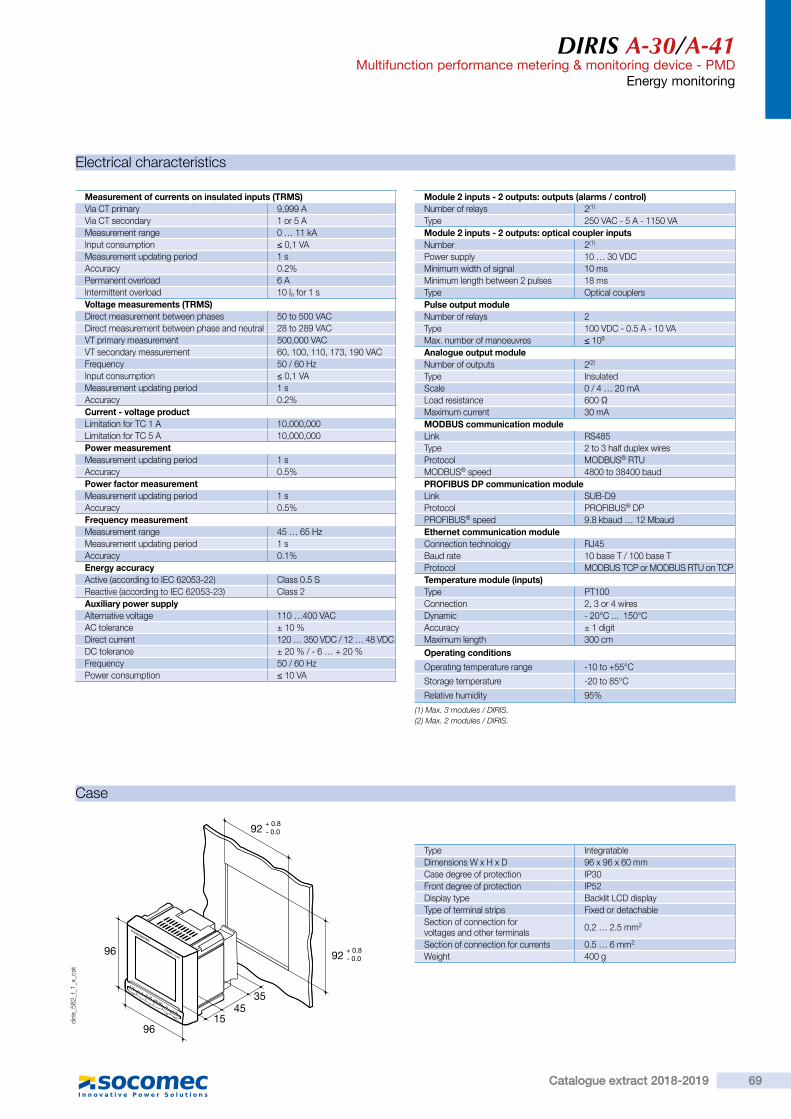
DIRIS A-30/A-41Multifunction performance metering & monitoring device - PMDEnergy monitoring
Accessories
traf
o_02
4_a_
2_ca
t
Current transformer (see page
traf
o_07
7_b_
2_ca
t
diris
_720
_a_2
_cat
IP65 protection.
Terminals
DIRIS A-30
A U XV3 VNV1 V2
I3I2I1
S2S1 S2S1 S2S1
diris
_569
_a_1
_x_c
at
S1 - S2 : current inputs
AUX : auxiliary power supplies Us
V1- V2 - V3 - VN : voltage inputs
DIRIS A-30
0 V - +
R = 120 RS4850n
1
DIRIS A-30 / A-41diris
_571
_a_1
_x_c
at
RS485 link.R = 120 Ω : internal resistance for the RS485 link.
5 6 7 8
DIRIS A-30 / A-41
0/4-20 mAOUT 1
0/4-20 mAOUT 2
-+ -+
diris
_573
_a_1
_x_c
at
5 - 6 : analogue output n°1.7 - 8 : analogue output n°2.
1 2 3 4
DIRIS A-30 / A-41OUT 1 OUT 2
diris
_572
_a_1
_x_c
at
1 - 2 : pulse output n°1.3 - 4 : relay output n°2.
9 10 11 12
DIRIS A-30 / A-41IN 1
OUT 2A-Cd
OUT 1A-Cd
1 3 14 15 16
IN 2- + - +
diris
_574
_b_1
_x_c
at
9 - 10 : relay output n°1.11 - 12 : relay output n°2.13 - 14 : optical input n°1.15 - 16 : optical input n°2.
17 18
DIRIS A-30 / A-41
INsynchro
-+
diris
_683
_a_1
_x_c
at
17 - 18 : synchronisation input.
DIRIS A-30 / A-41
10 BASE T100 BASE T
RJ45
diris
_752
_a_1
_x_c
at
DIRIS A-41
A U XV3 VNV1 V2
I3I2I1
S2S1 S2S1 S2S1
IN
S2S1
diris
_570
_a_1
_x_c
at
S1 - S2 : current inputs
AUX: auxiliary power supplies Us
V1 - V2 - V3 - VN : voltage inputs
DIRIS A-41
DIRIS A-30 / A-41
22 23 24 262519 20 21
27 28 29 30
sonde 1 sonde 2
sonde 3diris
_753
_a_1
_fr_
cat
DIRIS A-30 / A-41
10 BASE T100 BASE T
RJ45
0 V +-
PasserelleRS485 R = 120Ω
0n1
diris
_751
_c_1
_fr_
cat
Communication module Analogue output modulePulse output module
2 input / 2 output module Memory module
Ethernet module
Temperature module
Ethernet module + RS485 MODBUS gateway
Probe 119 : red20 : red21 : white22 : white
Probe 223 : red24 : red25 : white26 : white
Probe 327: red28 : red29 : white30 : white
DIRIS A-30/A-41Multifunction performance metering & monitoring device - PMD
Energy monitoring
Case
Type IntegratableDimensions W x H x D 96 x 96 x 60 mmCase degree of protection IP30Front degree of protection IP52Display type Backlit LCD displayType of terminal strips Fixed or detachableSection of connection for voltages and other terminals 0,2 … 2.5 mm2
Section of connection for currents 0.5 … 6 mm2
Weight 400 g
Measurement of currents on insulated inputs (TRMS)Via CT primary 9,999 AVia CT secondary 1 or 5 AMeasurement range 0 … 11 kAInput consumption ≤ 0,1 VAMeasurement updating period 1 sAccuracy 0.2%Permanent overload 6 AIntermittent overload 10 In for 1 sVoltage measurements (TRMS)Direct measurement between phases 50 to 500 VACDirect measurement between phase and neutral 28 to 289 VACVT primary measurement 500,000 VACVT secondary measurement 60, 100, 110, 173, 190 VACFrequency 50 / 60 HzInput consumption ≤ 0,1 VAMeasurement updating period 1 sAccuracy 0.2%Current - voltage productLimitation for TC 1 A 10,000,000Limitation for TC 5 A 10,000,000Power measurementMeasurement updating period 1 sAccuracy 0.5%Power factor measurementMeasurement updating period 1 sAccuracy 0.5%Frequency measurementMeasurement range 45 … 65 HzMeasurement updating period 1 sAccuracy 0.1%Energy accuracyActive (according to IEC 62053-22) Class 0.5 SReactive (according to IEC 62053-23) Class 2Auxiliary power supplyAlternative voltage 110 …400 VACAC tolerance ± 10 %Direct current 120 … 350 VDC / 12 … 48 VDCDC tolerance ± 20 % / - 6 … + 20 %Frequency 50 / 60 HzPower consumption ≤ 10 VA
Electrical characteristics
Module 2 inputs - 2 outputs: outputs (alarms / control)Number of relays 2(1)
Type 250 VAC - 5 A - 1150 VAModule 2 inputs - 2 outputs: optical coupler inputsNumber 2(1)
Power supply 10 … 30 VDCMinimum width of signal 10 msMinimum length between 2 pulses 18 msType Optical couplersPulse output moduleNumber of relays 2Type 100 VDC - 0.5 A - 10 VAMax. number of manoeuvres ≤ 108
Analogue output moduleNumber of outputs 2(2)
Type InsulatedScale 0 / 4 … 20 mALoad resistance 600 ΩMaximum current 30 mAMODBUS communication moduleLink RS485Type 2 to 3 half duplex wiresProtocol MODBUS® RTUMODBUS® speed 4800 to 38400 baudPROFIBUS DP communication moduleLink SUB-D9Protocol PROFIBUS® DPPROFIBUS® speed 9.8 kbaud … 12 MbaudEthernet communication moduleConnection technology RJ45Baud rate 10 base T / 100 base TProtocol MODBUS TCP or MODBUS RTU on TCPTemperature module (inputs)Type PT100Connection 2, 3 or 4 wiresDynamic - 20°C ... 150°CAccuracy ± 1 digitMaximum length 300 cmOperating conditions
Operating temperature range -10 to +55°C
Storage temperature -20 to 85°C
Relative humidity 95%
(1) Max. 3 modules / DIRIS.(2) Max. 2 modules / DIRIS.
DIRIS A4096
96
4515
35
92+ 0.8- 0.0
92+ 0.8- 0.0
diris
_582
_f_1
_x_c
at
69Catalogue extract 2018-2019 69Catalogue extract 2018-2019

DIRIS A-30/A-41Multifunction performance metering & monitoring device - PMDEnergy monitoring
Recommendation: When disconnecting the DIRIS, the secondary of each current transformer must be short-circuited. This operation can be carried out automatically by a SOCOMEC PTI, which can be found in the SOCOMEC catalogue: please consult us.In TNC mode, it is advisable to connect the DIRIS A-30/A-41 to earth using the functional earth module.
Balanced low-voltage network for DIRIS A-30
Connections
V1 V2 V3 VN
S2P1S1
NL1L2L3
I3I2I1
S2S1 S2S1 S2S1
1 1 1
diris
_392
_d_1
_x_c
at
The use of 1 TC reduces by 0.5% the accuracy of the phases, the current for which is worked out by vector calculation.
3/4 wires with 1 CTs
V1 V2 V3 VN
S2S1P1 L1
N
I3I2I1
S2S1 S2S1 S2S1
1
diris
_393
_e_1
_x_c
at
Single-phase
V1 V2 V3 VN
S2P1S1
L1L2
I3I2I1
S2S1 S2S1 S2S1
1 1
diris
_394
_d_1
_x_c
at
Two-phase
1. 0.5 A gG / 0.5 A class CC fuses. 1. 0.5 A gG / 0.5 A class CC fuses.
1. 0.5 A gG / 0.5 A class CC fuses.
Balanced low-voltage network for DIRIS A-30
NL1L2L3
S2
S2
P1S1
P1S1
V1 V2 V3 VN
I3I2I1
S2S1 S2S1 S2S1
1 1 1
diris
_395
_d_1
_x_c
at
3/4 wires with 3 CTs
1. 0.5 A gG / 0.5 A class CC fuses. The use of 2 TC reduces by 0.5% the accuracy of the phase, the current for which is worked out by vector calculation.
diris
_396
_d_1
_x_c
at
L1L2L3
S2
S2P1S1
P1S1
V1 V2 V3 VN
I3I2I1
S2S1 S2S1 S2S1
1 1 1
3 wires with 2 CTs
1. 0.5 A gG / 0.5 A class CC fuses.
The use of 2 TC reduces by 0.5% the accuracy of the phase, the current for which is worked out by vector calculation.
L1L2L3
S2P1S1
P1S1
V1 V2 V3 VN
I3I2I1
S2S1 S2S1 S2S1
1 1 1
diris
_397
_d_1
_x_c
at
3 wires with 2 CTs
1. 0.5 A gG / 0.5 A class CC fuses.
Balanced low-voltage network for DIRIS A-41
NL1L2L3
V1 V2 V3 VN
S2
S2P1S1
P1S1
I3I2I1
S2S1 S2S1 S2S1
1 1 1
S1 S2
P1S1
IN
diris
_575
_b_1
_x_c
at
4 wires with 4 CTs
1. 0.5 A gG / 0.5 A class CC fuses.
Additional information
RS485
0 V - +ON
LIYCY-CY
diris
_398
_c_1
_x_c
at
Communication via RS485 link
V1 V2 V3 N
L1L2L3
diris
_399
_b_1
_x_c
at
Connection of potential transformer for HV networks
A U X
110 / 400 VAC120 / 350 VDC
11
diris
_400
_i_1
_x_c
at
AC and DC auxiliary power supply
1. 0.5 A gG / 0.5 A class CC fuses.
DIRIS A-30/A-41Multifunction performance metering & monitoring device - PMD
Energy monitoring
References
Basic device DIRIS A-30 DIRIS A-41With TC on the neutral
Auxiliary power supply Us Part number Reference110 ... 400 VAC / 120 ... 350 VDC 4825 0403 4825 040412 ... 48 VDC 4825 0405 4825 0406
OptionsIntegratable modules(1) Part number ReferencePulse outputs 4825 0090 4825 0090RS485 MODBUS® communication 4825 0092 4825 0092Analogue outputs 4825 0093 4825 00932 inputs - 2 outputs 4825 0094 4825 0094Storage capability 4825 0097 4825 0097Ethernet communication (integrated web server function)(2) 4825 0203 4825 0203Ethernet communication + RS485 gateway (integrated web server function)(2) 4825 0204 4825 0204Temperature inputs. 4825 0206 4825 0206
(1) Ease of integration of additional functions (maximum 4 placements on A-30 and 3 on A-41).(2) Dimensions: 2 placements.
Accessories
Accessories To be orderedin multiples of Part number To be ordered
in multiples of Part number
IP65 protection. 1 4825 0089 1 4825 0089Integration kit for 144 x 96 mm cutout 1 4825 0088 1 4825 0088Fuse circuit breakers to protect voltage inputs (type RM) 3 pole 4 5601 0018 4 5601 0018Fuse circuit breakers to protect the auxiliary power supply (type RM) 1 pole + neutral 6 5601 0017 6 5601 0017
gG 10x38 0.5 A fuses 10 6012 0000 10 6012 0000Range of current transformers 1 See page 1 See pageFerrite for use with communication modules 1 4899 0011 4899 0011PT100 temperature probe, M6 screw 1 4825 0208 1 4825 0208PT100 temperature probe, M6 lug 1 4825 0209 1 4825 0209Associated DIRIS software See page
> Study, definition , advice, implementation , maintenance and training ... Our experts "Expert Services" offer complete support for the success of your project.
Expert Services
70 Catalogue extract 2018-201970 Catalogue extract 2018-2019

DIRIS A-30/A-41Multifunction performance metering & monitoring device - PMDEnergy monitoring
Recommendation: When disconnecting the DIRIS, the secondary of each current transformer must be short-circuited. This operation can be carried out automatically by a SOCOMEC PTI, which can be found in the SOCOMEC catalogue: please consult us.In TNC mode, it is advisable to connect the DIRIS A-30/A-41 to earth using the functional earth module.
Balanced low-voltage network for DIRIS A-30
Connections
V1 V2 V3 VN
S2P1S1
NL1L2L3
I3I2I1
S2S1 S2S1 S2S1
1 1 1
diris
_392
_d_1
_x_c
at
The use of 1 TC reduces by 0.5% the accuracy of the phases, the current for which is worked out by vector calculation.
3/4 wires with 1 CTs
V1 V2 V3 VN
S2S1P1 L1
N
I3I2I1
S2S1 S2S1 S2S1
1
diris
_393
_e_1
_x_c
at
Single-phase
V1 V2 V3 VN
S2P1S1
L1L2
I3I2I1
S2S1 S2S1 S2S1
1 1
diris
_394
_d_1
_x_c
at
Two-phase
1. 0.5 A gG / 0.5 A class CC fuses. 1. 0.5 A gG / 0.5 A class CC fuses.
1. 0.5 A gG / 0.5 A class CC fuses.
Balanced low-voltage network for DIRIS A-30
NL1L2L3
S2
S2
P1S1
P1S1
V1 V2 V3 VN
I3I2I1
S2S1 S2S1 S2S1
1 1 1
diris
_395
_d_1
_x_c
at
3/4 wires with 3 CTs
1. 0.5 A gG / 0.5 A class CC fuses. The use of 2 TC reduces by 0.5% the accuracy of the phase, the current for which is worked out by vector calculation.
diris
_396
_d_1
_x_c
at
L1L2L3
S2
S2P1S1
P1S1
V1 V2 V3 VN
I3I2I1
S2S1 S2S1 S2S1
1 1 1
3 wires with 2 CTs
1. 0.5 A gG / 0.5 A class CC fuses.
The use of 2 TC reduces by 0.5% the accuracy of the phase, the current for which is worked out by vector calculation.
L1L2L3
S2P1S1
P1S1
V1 V2 V3 VN
I3I2I1
S2S1 S2S1 S2S1
1 1 1
diris
_397
_d_1
_x_c
at
3 wires with 2 CTs
1. 0.5 A gG / 0.5 A class CC fuses.
Balanced low-voltage network for DIRIS A-41
NL1L2L3
V1 V2 V3 VN
S2
S2P1S1
P1S1
I3I2I1
S2S1 S2S1 S2S1
1 1 1
S1 S2
P1S1
IN
diris
_575
_b_1
_x_c
at
4 wires with 4 CTs
1. 0.5 A gG / 0.5 A class CC fuses.
Additional information
RS485
0 V - +ON
LIYCY-CY
diris
_398
_c_1
_x_c
at
Communication via RS485 link
V1 V2 V3 N
L1L2L3
diris
_399
_b_1
_x_c
at
Connection of potential transformer for HV networks
A U X
110 / 400 VAC120 / 350 VDC
11
diris
_400
_i_1
_x_c
at
AC and DC auxiliary power supply
1. 0.5 A gG / 0.5 A class CC fuses.
DIRIS A-30/A-41Multifunction performance metering & monitoring device - PMD
Energy monitoring
References
Basic device DIRIS A-30 DIRIS A-41With TC on the neutral
Auxiliary power supply Us Part number Reference110 ... 400 VAC / 120 ... 350 VDC 4825 0403 4825 040412 ... 48 VDC 4825 0405 4825 0406
OptionsIntegratable modules(1) Part number ReferencePulse outputs 4825 0090 4825 0090RS485 MODBUS® communication 4825 0092 4825 0092Analogue outputs 4825 0093 4825 00932 inputs - 2 outputs 4825 0094 4825 0094Storage capability 4825 0097 4825 0097Ethernet communication (integrated web server function)(2) 4825 0203 4825 0203Ethernet communication + RS485 gateway (integrated web server function)(2) 4825 0204 4825 0204Temperature inputs. 4825 0206 4825 0206
(1) Ease of integration of additional functions (maximum 4 placements on A-30 and 3 on A-41).(2) Dimensions: 2 placements.
Accessories
Accessories To be orderedin multiples of Part number To be ordered
in multiples of Part number
IP65 protection. 1 4825 0089 1 4825 0089Integration kit for 144 x 96 mm cutout 1 4825 0088 1 4825 0088Fuse circuit breakers to protect voltage inputs (type RM) 3 pole 4 5601 0018 4 5601 0018Fuse circuit breakers to protect the auxiliary power supply (type RM) 1 pole + neutral 6 5601 0017 6 5601 0017
gG 10x38 0.5 A fuses 10 6012 0000 10 6012 0000Range of current transformers 1 See page 1 See pageFerrite for use with communication modules 1 4899 0011 4899 0011PT100 temperature probe, M6 screw 1 4825 0208 1 4825 0208PT100 temperature probe, M6 lug 1 4825 0209 1 4825 0209Associated DIRIS software See page
> Study, definition , advice, implementation , maintenance and training ... Our experts "Expert Services" offer complete support for the success of your project.
Expert Services
71Catalogue extract 2018-2019 71Catalogue extract 2018-2019
40
See general catalogue
40
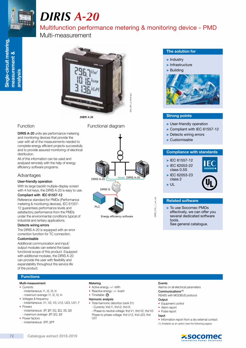
Sing
le-c
ircui
t met
erin
g,
mea
sure
men
t &
an
alys
isDIRIS A-20Multifunction performance metering & monitoring device - PMDMulti-measurement
DIRIS A-20
Function
DIRIS A-20 units are performance metering and monitoring devices that provide the user with all of the measurements needed to complete energy efficient projects successfully and to provide assured monitoring of electrical distribution.All of this information can be used and analysed remotely with the help of energy efficiency software programs.
> Industry > Infrastructure > Building
The solution for
> User-friendly operation > Compliant with IEC 61557-12 > Detects wiring errors > Customisable
Strong points
Functions
Multi-measurement • Currents- instantaneous: I1, I2, I3, In- maximum average: I1, I2, I3, In
• Voltages & frequency- instantaneous: V1, V2, V3, U12, U23, U31, F
• Powers- instantaneous: 3P, ΣP, 3Q, ΣQ, 3S, ΣS- maximum average: ΣP, ΣQ, ΣS
• Power factors- instantaneous: 3PF, ΣPF
Metering • Active energy: +/- kWh • Reactive energy: +/- kvarh • Timetable:
Harmonic analysis • Total harmonic distortion (rank 51)- Currents: thd I1, thd I2, thd I3- Phase-to-neutral voltage: thd V1, thd V2, thd V3 Phase-to-phase voltage: thd U12, thd U23, thd U31
EventsAlarms on all electrical parametersCommunications (1)
RS485 with MODBUS protocolOutput • Equipment control • Alarm report • Pulse report
Input • Information report from a dry external contact
(1) Available as an option (see the following pages).
RS485DIRIS A-20 DIRIS A-20
Energy efficiency software
PLC
DIRIS G
DIR
IS_5
76_i
_1_e
n_ca
t
AdvantagesUser-friendly operationWith its large backlit multiple-display screen with 4 hot keys, the DIRIS A-20 is easy to use.Compliant with IEC 61557-12Reference standard for PMDs (Performance metering & monitoring devices), IEC 61557-12 guarantees performance levels and satisfactory performance from the PMDs under the environmental conditions typical of industrial and tertiary applications.Detects wiring errorsThe DIRIS A-20 is equipped with an error correction function for TC connection.CustomisableAdditional communication and input/output modules can extend the basic functional scope of this product. Equipped with additional modules, the DIRIS A-20 can provide the user with flexibility and expandability throughout the service life of the product.
Functional diagram
> To use Socomec PMDs effectively, we can offer you several dedicated software tools.See page
Related software
> IEC 61557-12 > IEC 62053-22 class 0.5S
> IEC 62053-23 class 2
> UL
Compliance with standards
DIRIS A-20
diris
_981
_a_f
ront
.eps
DIRIS A-20Multifunction performance metering & monitoring device - PMD
Multi-measurement
54321
DIR
IS_9
81x_
a_1_
cat
1. Backlit LCD display2. Pushbutton for currents (instantaneous and maximum), THD currents
and the connection correction function.3. Pushbutton for voltages, frequency and THD voltages.4. Pushbutton for power (instantaneous and maximum), active, reactive
and effective, power factor.5. Pushbutton for energy sources and timer counter.
Front panel
Case
Type Plug-in
Dimensions L x H x P 96 x 96 x 60 mm
Case degree of protection IP30
Front degree of protection IP52
Display type Backlit LCD
Type of terminal strips Fixed or removable
Section for connection of voltages and other terminals 0.2 … 2.5 mm2
Section for connection of currents 0.5 … 6 mm2
Weight 400 g5/TEST 4 OK PROG
I V F P PF E
96
96
4535
15
92 + 0.8- 0.0
92 + 0.8- 0.0
DIR
IS_5
77_e
_1_x
_cat
Plug-in optional modules
DIR
IS_7
73_a
_1_c
at
diris
_445
_a_1
_cat 1 output that can be configured for:
• pulses: configurable (type, weight, duration) to kWh or kVarh.
• Monitoring: 3I, In, 3V, 3U, F, ΣP, ΣQ, ΣS, ΣPFL/C, THD 3I, THD 3V, THD 3U and timer meter.
• Equipment control
1 output
diris
_447
_a_1
_cat
RS485 link with MODBUS protocol (speed up to 38 400 baud).
3 inputs can be configured into: • Information report from an external contact.
1 output that can be configured for: • pulses: configurable (type, weight, duration) to kWh or kVarh. • Monitoring: 3I, In, 3V, 3U, F, ΣP, ΣQ, ΣS, ΣPFL/C, THD 3I, THD 3V, THD 3U and timer meter.
• Equipment control
Communication
3 inputs , 1 output
Accessoriestr
afo_
024_
a_2_
cat
Current transformer (see page
traf
o_07
7_b_
2_ca
t
DIR
IS_7
20_a
_2_c
at
IP65 protection
DIRIS® A-20
diris
_449
_a_1
_cat
72 Catalogue extract 2018-2019
See general catalogue.
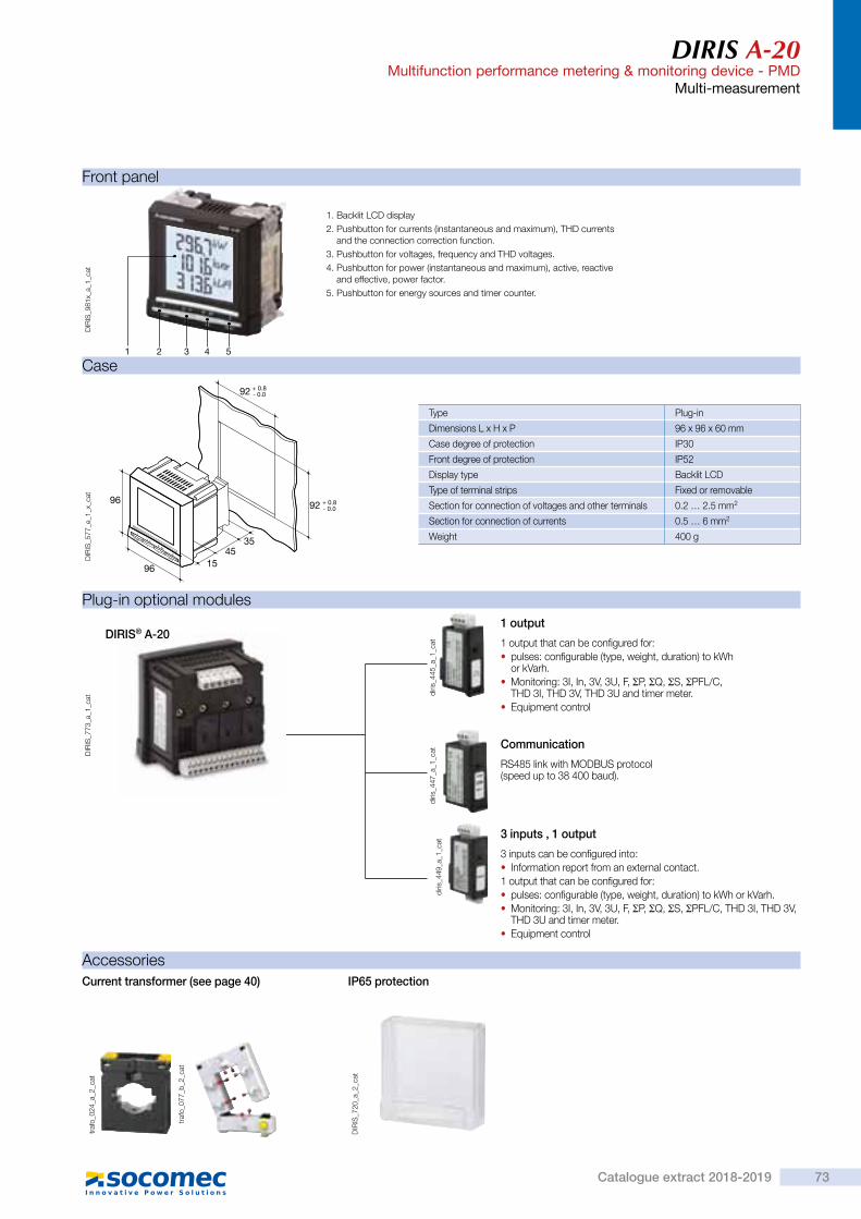
Sing
le-c
ircui
t met
erin
g,
mea
sure
men
t &
an
alys
is
DIRIS A-20Multifunction performance metering & monitoring device - PMDMulti-measurement
DIRIS A-20
Function
DIRIS A-20 units are performance metering and monitoring devices that provide the user with all of the measurements needed to complete energy efficient projects successfully and to provide assured monitoring of electrical distribution.All of this information can be used and analysed remotely with the help of energy efficiency software programs.
> Industry > Infrastructure > Building
The solution for
> User-friendly operation > Compliant with IEC 61557-12 > Detects wiring errors > Customisable
Strong points
Functions
Multi-measurement • Currents- instantaneous: I1, I2, I3, In- maximum average: I1, I2, I3, In
• Voltages & frequency- instantaneous: V1, V2, V3, U12, U23, U31, F
• Powers- instantaneous: 3P, ΣP, 3Q, ΣQ, 3S, ΣS- maximum average: ΣP, ΣQ, ΣS
• Power factors- instantaneous: 3PF, ΣPF
Metering • Active energy: +/- kWh • Reactive energy: +/- kvarh • Timetable:
Harmonic analysis • Total harmonic distortion (rank 51)- Currents: thd I1, thd I2, thd I3- Phase-to-neutral voltage: thd V1, thd V2, thd V3 Phase-to-phase voltage: thd U12, thd U23, thd U31
EventsAlarms on all electrical parametersCommunications (1)
RS485 with MODBUS protocolOutput • Equipment control • Alarm report • Pulse report
Input • Information report from a dry external contact
(1) Available as an option (see the following pages).
RS485DIRIS A-20 DIRIS A-20
Energy efficiency software
PLC
DIRIS G
DIR
IS_5
76_i
_1_e
n_ca
t
AdvantagesUser-friendly operationWith its large backlit multiple-display screen with 4 hot keys, the DIRIS A-20 is easy to use.Compliant with IEC 61557-12Reference standard for PMDs (Performance metering & monitoring devices), IEC 61557-12 guarantees performance levels and satisfactory performance from the PMDs under the environmental conditions typical of industrial and tertiary applications.Detects wiring errorsThe DIRIS A-20 is equipped with an error correction function for TC connection.CustomisableAdditional communication and input/output modules can extend the basic functional scope of this product. Equipped with additional modules, the DIRIS A-20 can provide the user with flexibility and expandability throughout the service life of the product.
Functional diagram
> To use Socomec PMDs effectively, we can offer you several dedicated software tools.See page
Related software
> IEC 61557-12 > IEC 62053-22 class 0.5S
> IEC 62053-23 class 2
> UL
Compliance with standards
DIRIS A-20
diris
_981
_a_f
ront
.eps
DIRIS A-20Multifunction performance metering & monitoring device - PMD
Multi-measurement
54321
DIR
IS_9
81x_
a_1_
cat
1. Backlit LCD display2. Pushbutton for currents (instantaneous and maximum), THD currents
and the connection correction function.3. Pushbutton for voltages, frequency and THD voltages.4. Pushbutton for power (instantaneous and maximum), active, reactive
and effective, power factor.5. Pushbutton for energy sources and timer counter.
Front panel
Case
Type Plug-in
Dimensions L x H x P 96 x 96 x 60 mm
Case degree of protection IP30
Front degree of protection IP52
Display type Backlit LCD
Type of terminal strips Fixed or removable
Section for connection of voltages and other terminals 0.2 … 2.5 mm2
Section for connection of currents 0.5 … 6 mm2
Weight 400 g5/TEST 4 OK PROG
I V F P PF E
96
96
4535
15
92 + 0.8- 0.0
92 + 0.8- 0.0
DIR
IS_5
77_e
_1_x
_cat
Plug-in optional modules
DIR
IS_7
73_a
_1_c
at
diris
_445
_a_1
_cat 1 output that can be configured for:
• pulses: configurable (type, weight, duration) to kWh or kVarh.
• Monitoring: 3I, In, 3V, 3U, F, ΣP, ΣQ, ΣS, ΣPFL/C, THD 3I, THD 3V, THD 3U and timer meter.
• Equipment control
1 output
diris
_447
_a_1
_cat
RS485 link with MODBUS protocol (speed up to 38 400 baud).
3 inputs can be configured into: • Information report from an external contact.
1 output that can be configured for: • pulses: configurable (type, weight, duration) to kWh or kVarh. • Monitoring: 3I, In, 3V, 3U, F, ΣP, ΣQ, ΣS, ΣPFL/C, THD 3I, THD 3V, THD 3U and timer meter.
• Equipment control
Communication
3 inputs , 1 output
Accessories
traf
o_02
4_a_
2_ca
t
Current transformer (see page
traf
o_07
7_b_
2_ca
t
DIR
IS_7
20_a
_2_c
at
IP65 protection
DIRIS® A-20
diris
_449
_a_1
_cat
73Catalogue extract 2018-2019
40)

DIRIS A-20Multifunction performance metering & monitoring device - PMDMulti-measurement
Low voltage balanced network
Connection
Voltage measurements (TRMS)Direct measurement between phases 50 … 500 VACDirect measurement between phase and neutral 28 … 289 VAC
Input consumption ≤ 0.1 VAMeasurement updating period 1 sAccuracy 0.2%Power measurementMeasurement updating period 1 sAccuracy 0.5%Power factor measurementMeasurement updating period 1 sAccuracy 0.5%Frequency measurementMeasurement range 45 … 65 HzMeasurement updating period 1 sAccuracy 0.1%
Energy accuracyActive (according to IEC 62053-22) Class 0.5 SReactive (in acc. with CEI 62053-23) Class 2Auxiliary power supplyAlternative voltage 110 … 400 VACAC tolerance ± 10%DC voltage 120 … 289 VDCDC tolerance ± 20%Frequency 50 / 60 HzPower consumption 10 VAPulse or alarm outputNumber 1Type 100 VDC - 0,5 A - 10 VAMax. number of manoeuvres ≤ 108
InputsNumber 3Power supply 10 … 30 VDCMinimum width of signal 10 msMinimum length between 2 pulses 18 msType Optical couplersCommunicationLink RS485Type 2 to 3 half duplex wiresProtocol MODBUS® in RTU modeMODBUS® speed 1400 … 38400 baudOperating conditionsOperating temperature range - 10 … + 55°CStorage temperature - 20 … + 85°CRelative humidity 95%
Electrical characteristics
Terminals
DIRIS A20
A U XV3 VNV1 V2
I3I2I1
S2S1 S2S1 S2S1
DIR
IS_5
78_a
_1_x
_cat S1 - S2 : current inputs.
AUX : auxiliary power supply Us.V1, V2, V3 & VN : voltage inputs.
0 V - +
R = 120RS4850n
1
DIRIS A20
DIR
IS_5
79_a
_1_x
_cat
RS485 link.R = 120 Ω : internal resistance for the RS485 link.
Module communication
1 8 19
DIRIS A20
OUT 11 9 18
DIRIS A20
OUT 1
1 2 13
IN 3
+ - + - + -
1 4 15
IN 2
1 6 17
IN 1
DIR
IS_5
80_b
_1_x
_cat
18 - 19 : output n°1
Output or alarm module Module with 3 inputs, 1 output
The 1CT solution reduces by 0.5% the accuracy of the phase for which the current is deduced by a vector calculation.
3/4 wires with 1 CT Single-phase Two-phase
Current measurement (TRMS)Via CT primary 9 999 AVia CT secondary 5 AMeasurement range 0 … 11 kAInput consumption 0.6 VAMeasurement updating period 1 sAccuracy 0.2%Permanent overload 6 AIntermittent overload 10 In over 1 sec
1. 0.5 A gG / 0.5 A class CC fuses.1. 0.5 A gG / 0.5 A class CC fuses.1. 0.5 A gG / 0.5 A class CC fuses.
Recommendation- For IT earthing systems, it is recommended that the CT secondary is not connected to earth.- When disconnecting the DIRIS, the secondary of each current transformer must be short-circuited. This operation can be carried out automatically
by a SOCOMEC PTI, which can be found in the SOCOMEC catalogue: please consult us.
diris
_392
_d_1
_x_c
at
V1 V2 V3 VN
S2P1S1
NL1L2L3
I3I2I1
S2S1 S2S1 S2S1
1 1 1
diris
_393
_d_1
_x_c
at
V1 V2 V3 VN
S2S1P1 L1
N
I3I2I1
S2S1 S2S1 S2S1
1
diris
_394
_d_1
_x_c
at
V1 V2 V3 VN
S2P1S1
L1L2
I3I2I1
S2S1 S2S1 S2S1
1 1
DIRIS A-20Multifunction performance metering & monitoring device - PMD
Multi-measurement
Low voltage unbalanced network
NL1L2L3
S2
S2
P1S1
P1S1
V1 V2 V3 VN
I3I2I1
S2S1 S2S1 S2S1
1 1 1
diris
_395
_d_1
_fr_
cat
3/4 wires with 3 CTs
L1L2L3
S2
S2P1S1
P1S1
V1 V2 V3 VN
I3I2I1
S2S1 S2S1 S2S1
1 1 1
diris
_396
_d_1
_fr_
cat
The 2CT solution reduces by 0.5% the accuracy of the phase for which the current is deduced by a vector calculation.
3 wires with 2 CTs
L1L2L3
S2P1S1
P1S1
V1 V2 V3 VN
I3I2I1
S2S1 S2S1 S2S1
1 1 1
diris
_397
_e_1
_x_c
at
The 2CT solution reduces by 0.5% the accuracy of the phase for which the current is deduced by a vector calculation.
3 wires with 2 CTs
References
Basic device DIRIS A-20Auxiliary power supply Us Part number110 … 400 VAC / 120 … 350 VDC 4825 0402OptionsPlug-in optional modules Part numberOn/Off output. 4825 0080RS485 MODBUS® communication 4825 00823 inputs, 1 output 4825 0083AccessoriesDesignation of accessories To be ordered in multiples of Part numberProtection IP65 1 4825 0089Plug-in kit for cutout 144 x 96 mm 1 4825 0088Fuse circuit breakers to protect voltage inputs (type RM) 3 pole 4 5601 0018Fuse circuit breakers to protect the auxiliary power supply (type RM) 1 pole + neutral 6 5601 0017gG 10x38 0.5 A fuses 10 6012 0000Ferrite for use with communication modules 1 4899 0011Current transformer range 1Software associated with DIRIS
1. 0.5 A gG / 0.5 A class CC fuses.
Additional information
RS485
0 V - +ON
LIYCY-CY
diris
_398
_c_1
_x_c
at
Communication via RS485 link
A U X
110 / 400 VAC120 / 350 VDC
11
diris
_400
_i_1
_fr_
cat
AC and DC auxiliary power supply
1. 0.5 A gG / 0.5 A class CC fuses.
1. 0.5 A gG / 0.5 A class CC fuses. 1. 0.5 A gG / 0.5 A class CC fuses.
> Study, definition , advice, implementation , maintenance and training ... Our experts "Expert Services" offer complete support for the success of your project.
Expert Services
74 Catalogue extract 2018-2019

DIRIS A-20Multifunction performance metering & monitoring device - PMDMulti-measurement
Low voltage balanced network
Connection
Voltage measurements (TRMS)Direct measurement between phases 50 … 500 VACDirect measurement between phase and neutral 28 … 289 VAC
Input consumption ≤ 0.1 VAMeasurement updating period 1 sAccuracy 0.2%Power measurementMeasurement updating period 1 sAccuracy 0.5%Power factor measurementMeasurement updating period 1 sAccuracy 0.5%Frequency measurementMeasurement range 45 … 65 HzMeasurement updating period 1 sAccuracy 0.1%
Energy accuracyActive (according to IEC 62053-22) Class 0.5 SReactive (in acc. with CEI 62053-23) Class 2Auxiliary power supplyAlternative voltage 110 … 400 VACAC tolerance ± 10%DC voltage 120 … 289 VDCDC tolerance ± 20%Frequency 50 / 60 HzPower consumption 10 VAPulse or alarm outputNumber 1Type 100 VDC - 0,5 A - 10 VAMax. number of manoeuvres ≤ 108
InputsNumber 3Power supply 10 … 30 VDCMinimum width of signal 10 msMinimum length between 2 pulses 18 msType Optical couplersCommunicationLink RS485Type 2 to 3 half duplex wiresProtocol MODBUS® in RTU modeMODBUS® speed 1400 … 38400 baudOperating conditionsOperating temperature range - 10 … + 55°CStorage temperature - 20 … + 85°CRelative humidity 95%
Electrical characteristics
Terminals
DIRIS A20
A U XV3 VNV1 V2
I3I2I1
S2S1 S2S1 S2S1
DIR
IS_5
78_a
_1_x
_cat S1 - S2 : current inputs.
AUX : auxiliary power supply Us.V1, V2, V3 & VN : voltage inputs.
0 V - +
R = 120RS4850n
1
DIRIS A20
DIR
IS_5
79_a
_1_x
_cat
RS485 link.R = 120 Ω : internal resistance for the RS485 link.
Module communication
1 8 19
DIRIS A20
OUT 11 9 18
DIRIS A20
OUT 1
1 2 13
IN 3
+ - + - + -
1 4 15
IN 2
1 6 17
IN 1
DIR
IS_5
80_b
_1_x
_cat
18 - 19 : output n°1
Output or alarm module Module with 3 inputs, 1 output
The 1CT solution reduces by 0.5% the accuracy of the phase for which the current is deduced by a vector calculation.
3/4 wires with 1 CT Single-phase Two-phase
Current measurement (TRMS)Via CT primary 9 999 AVia CT secondary 5 AMeasurement range 0 … 11 kAInput consumption 0.6 VAMeasurement updating period 1 sAccuracy 0.2%Permanent overload 6 AIntermittent overload 10 In over 1 sec
1. 0.5 A gG / 0.5 A class CC fuses.1. 0.5 A gG / 0.5 A class CC fuses.1. 0.5 A gG / 0.5 A class CC fuses.
Recommendation- For IT earthing systems, it is recommended that the CT secondary is not connected to earth.- When disconnecting the DIRIS, the secondary of each current transformer must be short-circuited. This operation can be carried out automatically
by a SOCOMEC PTI, which can be found in the SOCOMEC catalogue: please consult us.
diris
_392
_d_1
_x_c
at
V1 V2 V3 VN
S2P1S1
NL1L2L3
I3I2I1
S2S1 S2S1 S2S1
1 1 1
diris
_393
_d_1
_x_c
at
V1 V2 V3 VN
S2S1P1 L1
N
I3I2I1
S2S1 S2S1 S2S1
1
diris
_394
_d_1
_x_c
at
V1 V2 V3 VN
S2P1S1
L1L2
I3I2I1
S2S1 S2S1 S2S1
1 1
DIRIS A-20Multifunction performance metering & monitoring device - PMD
Multi-measurement
Low voltage unbalanced network
NL1L2L3
S2
S2
P1S1
P1S1
V1 V2 V3 VN
I3I2I1
S2S1 S2S1 S2S1
1 1 1
diris
_395
_d_1
_fr_
cat
3/4 wires with 3 CTs
L1L2L3
S2
S2P1S1
P1S1
V1 V2 V3 VN
I3I2I1
S2S1 S2S1 S2S1
1 1 1
diris
_396
_d_1
_fr_
cat
The 2CT solution reduces by 0.5% the accuracy of the phase for which the current is deduced by a vector calculation.
3 wires with 2 CTs
L1L2L3
S2P1S1
P1S1
V1 V2 V3 VN
I3I2I1
S2S1 S2S1 S2S1
1 1 1
diris
_397
_e_1
_x_c
at
The 2CT solution reduces by 0.5% the accuracy of the phase for which the current is deduced by a vector calculation.
3 wires with 2 CTs
References
Basic device DIRIS A-20Auxiliary power supply Us Part number110 … 400 VAC / 120 … 350 VDC 4825 0402OptionsPlug-in optional modules Part numberOn/Off output. 4825 0080RS485 MODBUS® communication 4825 00823 inputs, 1 output 4825 0083AccessoriesDesignation of accessories To be ordered in multiples of Part numberProtection IP65 1 4825 0089Plug-in kit for cutout 144 x 96 mm 1 4825 0088Fuse circuit breakers to protect voltage inputs (type RM) 3 pole 4 5601 0018Fuse circuit breakers to protect the auxiliary power supply (type RM) 1 pole + neutral 6 5601 0017gG 10x38 0.5 A fuses 10 6012 0000Ferrite for use with communication modules 1 4899 0011Current transformer range 1Software associated with DIRIS
1. 0.5 A gG / 0.5 A class CC fuses.
Additional information
RS485
0 V - +ON
LIYCY-CY
diris
_398
_c_1
_x_c
at
Communication via RS485 link
A U X
110 / 400 VAC120 / 350 VDC
11
diris
_400
_i_1
_fr_
cat
AC and DC auxiliary power supply
1. 0.5 A gG / 0.5 A class CC fuses.
1. 0.5 A gG / 0.5 A class CC fuses. 1. 0.5 A gG / 0.5 A class CC fuses.
> Study, definition , advice, implementation , maintenance and training ... Our experts "Expert Services" offer complete support for the success of your project.
Expert Services
75Catalogue extract 2018-2019
See general catalogueSee page 40

Sing
le-c
ircui
t met
erin
g,
mea
sure
men
t &
an
alys
isDIRIS A-10Multifunction meters - PMDmodular multifunction meter
Function
Advantages
The DIRIS A-10 is a modular multifunction meter for measuring electrical values in low voltage networks.It allows all electrical parameters to be displayed and utilised for communication and/or output functions.
Easy to useFive direct access pushbuttons enable all measurements to be clearly viewed on its backlit LCD display.
Integrated temperature sensorIt allows variations in temperature to be detected.
Detects wiring errorsAn integrated test function can be utilised to detect incorrect wiring and to automatically correct CT installation errors.
Compliant with IEC 61557-12IEC 61557-12 is a high-level standard for all PMDs (Performance Monitoring Devices) that are designed to measure and monitor electrical parameters in distribution networks.Compliance with IEC 61557-12 ensures a high level of equipment performance, in terms of metrology, and the mechanical and environmental aspects (EMC, temperature, etc.).
> Industry > Infrastructures > Tertiary
The solution for
> Easy to use > Integrated temperature sensor
> Detects wiring errors > Compliant with IEC 61557-12
Strong points
Functions
Multi-measurement • Currents- instantaneous: I1, I2, I3, In- maximum average: I1, I2, I3, In
• Voltages & frequency- instantaneous: V1, V2, V3, U12, U23, U31, F
• Power- instantaneous: 3P, ΣP, 3Q, ΣQ, 3S, ΣS- maximum average: ΣP, ΣQ, ΣS
• Power factors- instantaneous: 3PF, ΣPF
• Metering • Active energy: +/- kWh • Reactive energy: +/- kVarh
• Hours: • Harmonic analysis • Total harmonic distortion (level 51)- Currents: thd I1, thd I2, thd I3- Phase-to-neutral voltage: thd V1, thd V2, thd V3- Phase-to-phase voltage: thd U12, thd U23,
thd U31Dual tariff functionSelection of one out of 2 billing tariffs
EventsAlarms on all electrical valuesCommunications(1)
RS485 with MODBUS protocol
Input • Tariff selection • Remote device status
Output • Remote command of device • Alarm report • Pulse report
(1) Available on specific version (see the following pages).
485
ETHGeneral measurementreport
Curves for current per phase
PC
PLC
Energy efficiency software
RS485DIRIS A-10 DIRIS A-10
TEST
OK
PROG
TEST
OK
PROG
diris
_808
_f_1
_gb_
cat
Principle diagram
> IEC 61557-12 > IEC 62053-22 class 0.5S
> IEC 62053-23 class 2
> UL
Conformity to standards
DIRIS A-10di
ris_9
78_a
_fro
nt.e
ps
DIRIS A-10Multifunction meters - PMDmodular multifunction meter
1. Backlit LCD display.2. Direct access key for currents (instant and maximum), current THD and test function.3. Direct access key for voltages, frequency and voltage THD.4. Direct access key for active, reactive and apparent power (instantaneous and max. values) and
power factor.5. Direct access key for energies.6. Pushbutton for hour meter, temperature and programming menu access.7. Metrological LED.
Front panel
Case
Type modular
Number of modules 4
Dimensions W x H x D 72 x 90 x 64 mm
Case degree of protection IP 30
Front degree of protection IP 52
Display type backlit LCD display
Voltage and current connection cross-section 4 mm2
Connection cross-section for AUX supply, input, output and comms. 2.5 mm2
Weight 205 g (4825 0010) - 215 g (4825 0011)
72
90 45
44
64
diris
_809
_b_1
_x_c
at
Current measurement (TRMS)Via CT primary 9 999 AVia CT secondary 5 AMeasurement range 0 … 11 kAInput consumption 0.6 VAMeasurement updating period 1 sAccuracy 0.2 %Permanent overload 6 AIntermittent overload 10 In for 1 sVoltage measurements (TRMS)Direct measurement between phases 50 … 500 VACDirect measurement between phase and neutral 28 … 289 VACInput consumption ≤ 0.1 VAMeasurement updating period 1 sAccuracy 0.2 %Power measurementMeasurement updating period 1 sAccuracy 0.5 %Power factor measurementMeasurement updating period 1 sAccuracy 0.5 %Frequency measurementMeasurement range 45 … 65 HzMeasurement updating period 1 sAccuracy 0.1 %
Energy accuracyActive (according to IEC 62053-22) Class 0.5 SReactive (according to IEC 62053-23) Class 2Auxiliary power supplyAlternating voltage 110 … 277 VACAC tolerance ± 15 %Frequency 50 / 60 HzConsumption < 3 VADigital output (pulses or on/off)Number 1Type 20 / 30 VDC - 0.5 A - 10 VAMax. number of operations ≤ 108
CommunicationLink RS485Type 2 … 3 half duplex wiresProtocol MODBUS RTUMODBUS® speed 2400 … 38400 baudsOperating conditionsOperating temperature - 10 … + 55 °CStorage temperature - 20 … + 70 °CRelative humidity 85 %
Electrical characteristics
Input (tariff)Number 1Type 0 VAC: T1 / 200-277 VAC: T2
1
234567
diris
_978
x_a_
1_ca
t
76 Catalogue extract 2018-2019

Sing
le-c
ircui
t met
erin
g,
mea
sure
men
t &
an
alys
is
DIRIS A-10Multifunction meters - PMDmodular multifunction meter
Function
Advantages
The DIRIS A-10 is a modular multifunction meter for measuring electrical values in low voltage networks.It allows all electrical parameters to be displayed and utilised for communication and/or output functions.
Easy to useFive direct access pushbuttons enable all measurements to be clearly viewed on its backlit LCD display.
Integrated temperature sensorIt allows variations in temperature to be detected.
Detects wiring errorsAn integrated test function can be utilised to detect incorrect wiring and to automatically correct CT installation errors.
Compliant with IEC 61557-12IEC 61557-12 is a high-level standard for all PMDs (Performance Monitoring Devices) that are designed to measure and monitor electrical parameters in distribution networks.Compliance with IEC 61557-12 ensures a high level of equipment performance, in terms of metrology, and the mechanical and environmental aspects (EMC, temperature, etc.).
> Industry > Infrastructures > Tertiary
The solution for
> Easy to use > Integrated temperature sensor
> Detects wiring errors > Compliant with IEC 61557-12
Strong points
Functions
Multi-measurement • Currents- instantaneous: I1, I2, I3, In- maximum average: I1, I2, I3, In
• Voltages & frequency- instantaneous: V1, V2, V3, U12, U23, U31, F
• Power- instantaneous: 3P, ΣP, 3Q, ΣQ, 3S, ΣS- maximum average: ΣP, ΣQ, ΣS
• Power factors- instantaneous: 3PF, ΣPF
• Metering • Active energy: +/- kWh • Reactive energy: +/- kVarh
• Hours: • Harmonic analysis • Total harmonic distortion (level 51)- Currents: thd I1, thd I2, thd I3- Phase-to-neutral voltage: thd V1, thd V2, thd V3- Phase-to-phase voltage: thd U12, thd U23,
thd U31Dual tariff functionSelection of one out of 2 billing tariffs
EventsAlarms on all electrical valuesCommunications(1)
RS485 with MODBUS protocol
Input • Tariff selection • Remote device status
Output • Remote command of device • Alarm report • Pulse report
(1) Available on specific version (see the following pages).
485
ETHGeneral measurementreport
Curves for current per phase
PC
PLC
Energy efficiency software
RS485DIRIS A-10 DIRIS A-10
TEST
OK
PROG
TEST
OK
PROG
diris
_808
_f_1
_gb_
cat
Principle diagram
> IEC 61557-12 > IEC 62053-22 class 0.5S
> IEC 62053-23 class 2
> UL
Conformity to standards
DIRIS A-10
diris
_978
_a_f
ront
.eps
DIRIS A-10Multifunction meters - PMDmodular multifunction meter
1. Backlit LCD display.2. Direct access key for currents (instant and maximum), current THD and test function.3. Direct access key for voltages, frequency and voltage THD.4. Direct access key for active, reactive and apparent power (instantaneous and max. values) and
power factor.5. Direct access key for energies.6. Pushbutton for hour meter, temperature and programming menu access.7. Metrological LED.
Front panel
Case
Type modular
Number of modules 4
Dimensions W x H x D 72 x 90 x 64 mm
Case degree of protection IP 30
Front degree of protection IP 52
Display type backlit LCD display
Voltage and current connection cross-section 4 mm2
Connection cross-section for AUX supply, input, output and comms. 2.5 mm2
Weight 205 g (4825 0010) - 215 g (4825 0011)
72
90 45
44
64
diris
_809
_b_1
_x_c
at
Current measurement (TRMS)Via CT primary 9 999 AVia CT secondary 5 AMeasurement range 0 … 11 kAInput consumption 0.6 VAMeasurement updating period 1 sAccuracy 0.2 %Permanent overload 6 AIntermittent overload 10 In for 1 sVoltage measurements (TRMS)Direct measurement between phases 50 … 500 VACDirect measurement between phase and neutral 28 … 289 VACInput consumption ≤ 0.1 VAMeasurement updating period 1 sAccuracy 0.2 %Power measurementMeasurement updating period 1 sAccuracy 0.5 %Power factor measurementMeasurement updating period 1 sAccuracy 0.5 %Frequency measurementMeasurement range 45 … 65 HzMeasurement updating period 1 sAccuracy 0.1 %
Energy accuracyActive (according to IEC 62053-22) Class 0.5 SReactive (according to IEC 62053-23) Class 2Auxiliary power supplyAlternating voltage 110 … 277 VACAC tolerance ± 15 %Frequency 50 / 60 HzConsumption < 3 VADigital output (pulses or on/off)Number 1Type 20 / 30 VDC - 0.5 A - 10 VAMax. number of operations ≤ 108
CommunicationLink RS485Type 2 … 3 half duplex wiresProtocol MODBUS RTUMODBUS® speed 2400 … 38400 baudsOperating conditionsOperating temperature - 10 … + 55 °CStorage temperature - 20 … + 70 °CRelative humidity 85 %
Electrical characteristics
Input (tariff)Number 1Type 0 VAC: T1 / 200-277 VAC: T2
1
234567
diris
_978
x_a_
1_ca
t
77Catalogue extract 2018-2019
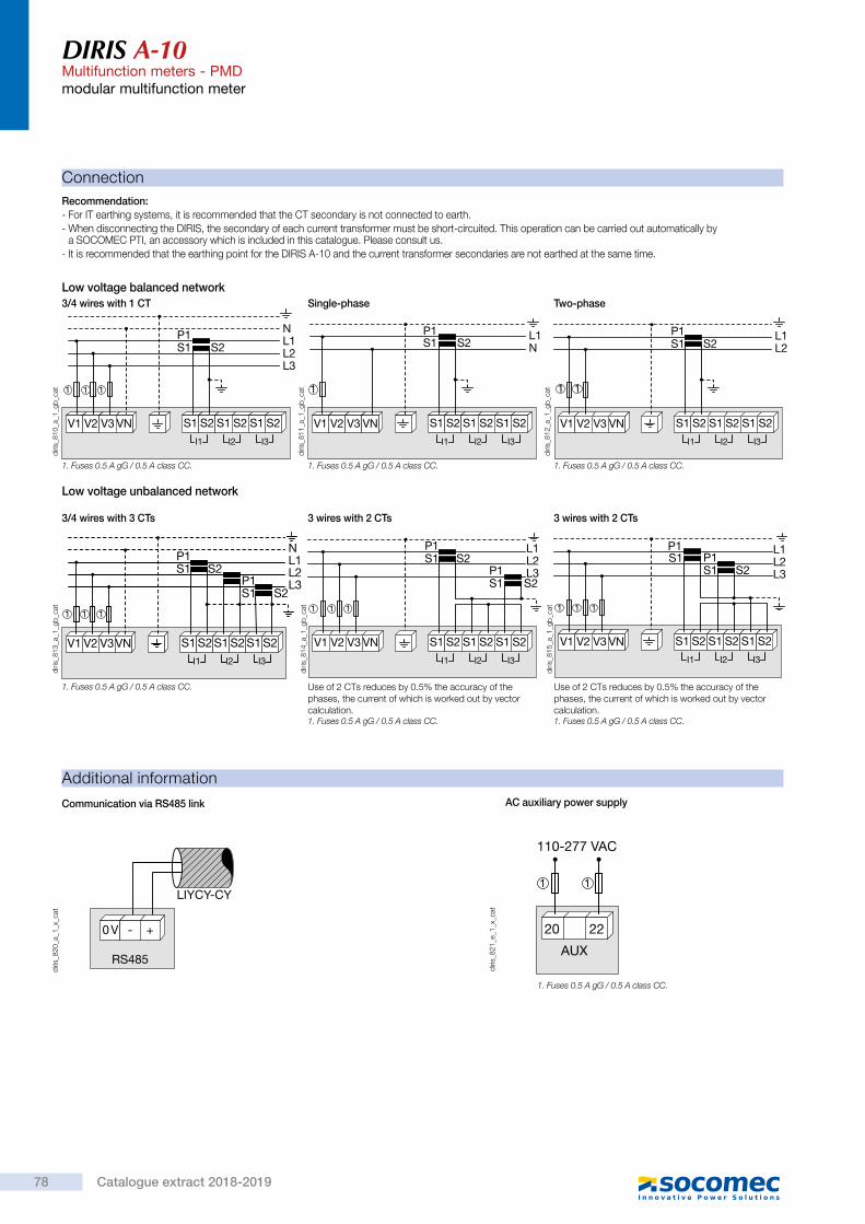
DIRIS A-10Multifunction meters - PMDmodular multifunction meter
ConnectionRecommendation:- For IT earthing systems, it is recommended that the CT secondary is not connected to earth.- When disconnecting the DIRIS, the secondary of each current transformer must be short-circuited. This operation can be carried out automatically by
a SOCOMEC PTI, an accessory which is included in this catalogue. Please consult us.- It is recommended that the earthing point for the DIRIS A-10 and the current transformer secondaries are not earthed at the same time.
V1 V2 V3 VN
S2P1S1
NL1L2L3
I3I2I1
S2S1 S2S1 S2S1
1 1 1
diris
_810
_a_1
_gb_
cat
3/4 wires with 1 CT
V1 V2 V3 VN
S2P1S1
L1N
I3I2I1
S2S1 S2S1 S2S1
1
diris
_811
_a_1
_gb_
cat
Single-phase
V1 V2 V3 VN
S2P1S1
L1L2
I3I2I1
S2S1 S2S1 S2S1
1 1
diris
_812
_a_1
_gb_
cat
Two-phase
Additional information
RS485
0 V - +
LIYCY-CY
diris
_820
_a_1
_x_c
at
Communication via RS485 link
AUX
110-277 VAC
20 22
11
diris
_821
_e_1
_x_c
at
AC auxiliary power supply
Low voltage unbalanced network
NL1L2L3
S2
S2P1S1
P1S1
V1 V2 V3VNI3I2I1
S2S1 S2S1 S2S1
1 1 1
diris
_813
_a_1
_gb_
cat
3/4 wires with 3 CTs
L1L2L3S2
S2P1S1
P1S1
V1 V2 V3 VNI3I2I1
S2S1 S2S1 S2S1
1 1 1
diris
_814
_a_1
_gb_
cat
Use of 2 CTs reduces by 0.5% the accuracy of the phases, the current of which is worked out by vector calculation.
3 wires with 2 CTs
L1L2L3S2
P1S1
P1S1
V1 V2 V3 VNI3I2I1
S2S1 S2S1 S2S1
1 1 1
diris
_815
_a_1
_gb_
cat
Use of 2 CTs reduces by 0.5% the accuracy of the phases, the current of which is worked out by vector calculation.
3 wires with 2 CTs
Low voltage balanced network
1. Fuses 0.5 A gG / 0.5 A class CC. 1. Fuses 0.5 A gG / 0.5 A class CC. 1. Fuses 0.5 A gG / 0.5 A class CC.
1. Fuses 0.5 A gG / 0.5 A class CC.1. Fuses 0.5 A gG / 0.5 A class CC.
1. Fuses 0.5 A gG / 0.5 A class CC.
1. Fuses 0.5 A gG / 0.5 A class CC.
DIRIS A-10Multifunction meters - PMDmodular multifunction meter
Terminals
DIRIS A-10
20 2216 212 14
I3I2I1
31 75 119
A U XV3 VNV1 V2 S2S1 S2S1 S2S1
18
diris
_816
_a_1
_x_c
at
AUX: auxiliary power supply Us.V1, V2, V3 & VN: voltage inputs.
S1 - S2: current inputs.
1 3 15 170 V + -
RS485
DIRIS A-10 diris
_816
_a_1
_x_c
at
RS485 link.
Communication terminals
4 6
DIRIS A-10
OUT 1
diris
_819
_b_1
_x_c
at
4 - 6 : output n°1
Pulse or alarm output terminals
8 10
DIRIS A-10
IN 1
diris
_818
_a_1
_x_c
at
8 - 10 : input n°1
Input terminals
References
Basic device DIRIS A-10Description ReferenceDIRIS A-10 4825 0400DIRIS A-10 with RS485 MODBUS communication 4825 0401Description of accessories To be ordered in multiples of ReferenceFuse disconnect switches for the protection of voltage inputs (type RM) 3 poles 4 5701 0018Fuse disconnect switches for the protection of the auxiliary supply (type RM) 1 pole + neutral 6 5701 0017Fuses type gG 10x38 0.5 A 10 6012 0000Current transformer range 1Management software for DIRIS
> Study, definition, advice, implementation, maintenance and training… Our experts “Expert Services” offer complete support for the success of your project.
Expert Services
78 Catalogue extract 2018-2019
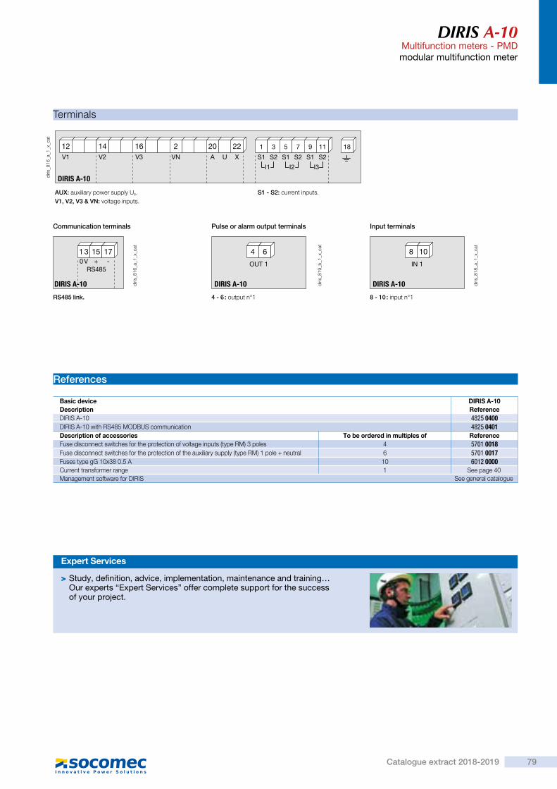
DIRIS A-10Multifunction meters - PMDmodular multifunction meter
ConnectionRecommendation:- For IT earthing systems, it is recommended that the CT secondary is not connected to earth.- When disconnecting the DIRIS, the secondary of each current transformer must be short-circuited. This operation can be carried out automatically by
a SOCOMEC PTI, an accessory which is included in this catalogue. Please consult us.- It is recommended that the earthing point for the DIRIS A-10 and the current transformer secondaries are not earthed at the same time.
V1 V2 V3 VN
S2P1S1
NL1L2L3
I3I2I1
S2S1 S2S1 S2S1
1 1 1
diris
_810
_a_1
_gb_
cat
3/4 wires with 1 CT
V1 V2 V3 VN
S2P1S1
L1N
I3I2I1
S2S1 S2S1 S2S1
1
diris
_811
_a_1
_gb_
cat
Single-phase
V1 V2 V3 VN
S2P1S1
L1L2
I3I2I1
S2S1 S2S1 S2S1
1 1
diris
_812
_a_1
_gb_
cat
Two-phase
Additional information
RS485
0 V - +
LIYCY-CY
diris
_820
_a_1
_x_c
at
Communication via RS485 link
AUX
110-277 VAC
20 22
11
diris
_821
_e_1
_x_c
at
AC auxiliary power supply
Low voltage unbalanced network
NL1L2L3
S2
S2P1S1
P1S1
V1 V2 V3VNI3I2I1
S2S1 S2S1 S2S1
1 1 1
diris
_813
_a_1
_gb_
cat
3/4 wires with 3 CTs
L1L2L3S2
S2P1S1
P1S1
V1 V2 V3 VNI3I2I1
S2S1 S2S1 S2S1
1 1 1
diris
_814
_a_1
_gb_
cat
Use of 2 CTs reduces by 0.5% the accuracy of the phases, the current of which is worked out by vector calculation.
3 wires with 2 CTs
L1L2L3S2
P1S1
P1S1
V1 V2 V3 VNI3I2I1
S2S1 S2S1 S2S1
1 1 1
diris
_815
_a_1
_gb_
cat
Use of 2 CTs reduces by 0.5% the accuracy of the phases, the current of which is worked out by vector calculation.
3 wires with 2 CTs
Low voltage balanced network
1. Fuses 0.5 A gG / 0.5 A class CC. 1. Fuses 0.5 A gG / 0.5 A class CC. 1. Fuses 0.5 A gG / 0.5 A class CC.
1. Fuses 0.5 A gG / 0.5 A class CC.1. Fuses 0.5 A gG / 0.5 A class CC.
1. Fuses 0.5 A gG / 0.5 A class CC.
1. Fuses 0.5 A gG / 0.5 A class CC.
DIRIS A-10Multifunction meters - PMDmodular multifunction meter
Terminals
DIRIS A-10
20 2216 212 14
I3I2I1
31 75 119
A U XV3 VNV1 V2 S2S1 S2S1 S2S1
18
diris
_816
_a_1
_x_c
at
AUX: auxiliary power supply Us.V1, V2, V3 & VN: voltage inputs.
S1 - S2: current inputs.
1 3 15 170 V + -
RS485
DIRIS A-10 diris
_816
_a_1
_x_c
at
RS485 link.
Communication terminals
4 6
DIRIS A-10
OUT 1
diris
_819
_b_1
_x_c
at
4 - 6 : output n°1
Pulse or alarm output terminals
8 10
DIRIS A-10
IN 1
diris
_818
_a_1
_x_c
at
8 - 10 : input n°1
Input terminals
References
Basic device DIRIS A-10Description ReferenceDIRIS A-10 4825 0400DIRIS A-10 with RS485 MODBUS communication 4825 0401Description of accessories To be ordered in multiples of ReferenceFuse disconnect switches for the protection of voltage inputs (type RM) 3 poles 4 5701 0018Fuse disconnect switches for the protection of the auxiliary supply (type RM) 1 pole + neutral 6 5701 0017Fuses type gG 10x38 0.5 A 10 6012 0000Current transformer range 1Management software for DIRIS
> Study, definition, advice, implementation, maintenance and training… Our experts “Expert Services” offer complete support for the success of your project.
Expert Services
79Catalogue extract 2018-2019
See page 40See general catalogue

So
ftw
are
suit
e
soft_
027_
a_1_
fr_ca
t
Function
The WEBVIEW web server embedded in DIRIS A-40 meters and in communication gateways (DIRIS G, DIRIS Digiware D-70, DATALOG H80/H81) delivers real-time monitoring of all measurements from up to 200 devices and displays the breakdown of energy consumption.
Uncover the causes of electrical disturbances and anticipate maintenance requirements thanks to historical records of multiple electrical parameters. Pre-set alarms defined by the user can be sent by e-mail. Users can access WEBVIEW via a web browser on a PC or a tablet.
Advantages
Plug & PlayQuickly configure WEBVIEW thanks to the automatic detection of Socomec devices. Create geographical and electrical hierarchies to reflect your installation and your processes.
Easy to useWEBVIEW centralises all the device measurements via a single clear and user friendly interface. The ergonomics of the display screens allow users to easily and quickly analyse the parameters and the behaviour of the installation.
Various functionsVery easy to configure and to use, WEBVIEW offers a wide range of features including real-time monitoring, alarm management and transmission by e-mail, multi-utility analysis (electricity, water, gas), power parameter logging and allocation of consumption by end-use and location.
> Plug & Play > Easy to use > Various functions
Strong points
> Industry > Building > Infrastructure > Local authority
The solution for
Type Hosting Functions Number of measurement devices
WEBVIEW-S DIRIS A-40 Monitor, Alarm, View 1
WEBVIEW-M
DIRIS G-30 / G-40 Monitor, View 32
DIRIS G-50 / G-60 Monitor, Alarm, View, 32
DIRIS Digiware D-70 Monitor, Alarm, View, Represent 32
WEBVIEW-L DATALOG H80 / H81 Monitor, Alarm, View, Represent 100/200
Characteristics
WEBVIEWMonitoring software for energy measurement and analysis
> IEC 62974-1(1)
(1) Energy Server standard applicable to WEBVIEW-M and L versions hosted on DIRIS G, DIRIS Digiware D-70 and DATALOG H80.
Compliance with standards
WEBVIEWMonitoring software for energy measurements and analysis
Monitor • Automatic detection of connected devices. • Summary of the parameters measured for the electrical network and loads. • Display of voltage, current, power, power factor, total harmonic distortion (THD) and harmonics per rank.
• Display of average/instantaneous values with min/max limits depending on the devices. • Total and partial energy consumption per load. • Input / output status. • Synchronisation of device clocks. • Graphical or table representation.
Alarm • Alarms for overloads, events and input status changes. • Display of alarms history. • Sorting by type, nature, criticality or state. • Alarms displayed on the main page. • Transmission of alarms by e-mail (SMTP).
View • Historical measurements and consumption. • Historical records of multiple power parameters. • Distribution of consumption by location, by end-use and by utility (water, gas, electricity…). • Export of consumption data in a CSV format.
Represent • Photoview: customised synoptic of the WEBVIEW environment via the upload of graphical files (building plans, electrical circuit diagrams, production processes…)
• Real time data tracking via the insertion of parameters on the background pictures (measurement points, alarms, text…).
• Display of the mapping of the measurement plan by cascading of several images.
References
Functions
Type Hosting Part number
WEBVIEW-S DIRIS A-40 4825 0501
WEBVIEW-M
DIRIS Digiware D-70 4829 0202DIRIS G-30 4829 0300DIRIS G-40 4829 0301DIRIS G-50 4829 0302DIRIS G-60 4829 0303
WEBVIEW-L 100DATALOG H80 4854 0020
DATALOG H81 (3G network) 4854 0021
WEBVIEW-L 200DATALOG H80 4854 0030
DATALOG H81 (3G network) 4854 0031
80 Catalogue extract 2018-2019

So
ftw
are
suit
e
soft_
027_
a_1_
fr_ca
t
Function
The WEBVIEW web server embedded in DIRIS A-40 meters and in communication gateways (DIRIS G, DIRIS Digiware D-70, DATALOG H80/H81) delivers real-time monitoring of all measurements from up to 200 devices and displays the breakdown of energy consumption.
Uncover the causes of electrical disturbances and anticipate maintenance requirements thanks to historical records of multiple electrical parameters. Pre-set alarms defined by the user can be sent by e-mail. Users can access WEBVIEW via a web browser on a PC or a tablet.
Advantages
Plug & PlayQuickly configure WEBVIEW thanks to the automatic detection of Socomec devices. Create geographical and electrical hierarchies to reflect your installation and your processes.
Easy to useWEBVIEW centralises all the device measurements via a single clear and user friendly interface. The ergonomics of the display screens allow users to easily and quickly analyse the parameters and the behaviour of the installation.
Various functionsVery easy to configure and to use, WEBVIEW offers a wide range of features including real-time monitoring, alarm management and transmission by e-mail, multi-utility analysis (electricity, water, gas), power parameter logging and allocation of consumption by end-use and location.
> Plug & Play > Easy to use > Various functions
Strong points
> Industry > Building > Infrastructure > Local authority
The solution for
Type Hosting Functions Number of measurement devices
WEBVIEW-S DIRIS A-40 Monitor, Alarm, View 1
WEBVIEW-M
DIRIS G-30 / G-40 Monitor, View 32
DIRIS G-50 / G-60 Monitor, Alarm, View, 32
DIRIS Digiware D-70 Monitor, Alarm, View, Represent 32
WEBVIEW-L DATALOG H80 / H81 Monitor, Alarm, View, Represent 100/200
Characteristics
WEBVIEWMonitoring software for energy measurement and analysis
> IEC 62974-1(1)
(1) Energy Server standard applicable to WEBVIEW-M and L versions hosted on DIRIS G, DIRIS Digiware D-70 and DATALOG H80.
Compliance with standards
WEBVIEWMonitoring software for energy measurements and analysis
Monitor • Automatic detection of connected devices. • Summary of the parameters measured for the electrical network and loads. • Display of voltage, current, power, power factor, total harmonic distortion (THD) and harmonics per rank.
• Display of average/instantaneous values with min/max limits depending on the devices. • Total and partial energy consumption per load. • Input / output status. • Synchronisation of device clocks. • Graphical or table representation.
Alarm • Alarms for overloads, events and input status changes. • Display of alarms history. • Sorting by type, nature, criticality or state. • Alarms displayed on the main page. • Transmission of alarms by e-mail (SMTP).
View • Historical measurements and consumption. • Historical records of multiple power parameters. • Distribution of consumption by location, by end-use and by utility (water, gas, electricity…). • Export of consumption data in a CSV format.
Represent • Photoview: customised synoptic of the WEBVIEW environment via the upload of graphical files (building plans, electrical circuit diagrams, production processes…)
• Real time data tracking via the insertion of parameters on the background pictures (measurement points, alarms, text…).
• Display of the mapping of the measurement plan by cascading of several images.
References
Functions
Type Hosting Part number
WEBVIEW-S DIRIS A-40 4825 0501
WEBVIEW-M
DIRIS Digiware D-70 4829 0202DIRIS G-30 4829 0300DIRIS G-40 4829 0301DIRIS G-50 4829 0302DIRIS G-60 4829 0303
WEBVIEW-L 100DATALOG H80 4854 0020
DATALOG H81 (3G network) 4854 0021
WEBVIEW-L 200DATALOG H80 4854 0030
DATALOG H81 (3G network) 4854 0031
81Catalogue extract 2018-2019
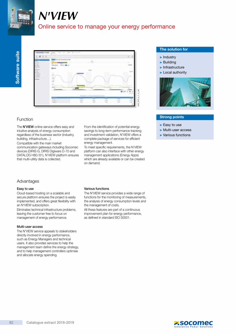
So
ftw
are
suit
e
soft_
043_
a_1_
x_ca
t
N'VIEWOnline service to manage your energy performance
Function
The N’VIEW online service offers easy and intuitive analysis of energy consumption regardless of the business sector (industry, building, infrastructure…).Compatible with the main market communication gateways including Socomec devices (DIRIS G, DIRIS Digiware D-70 and DATALOG H80 / 81), N’VIEW platform ensures that multi-utility data is collected.
From the identification of potential energy savings to long-term performance tracking and investment validation, N’VIEW offers a complete package of services for efficient energy management.To meet specific requirements, the N’VIEW platform can also interface with other energy management applications (Energy Apps) which are already available or can be created on demand.
Advantages
Easy to useCloud-based hosting on a scalable and secure platform ensures the project is easily implemented, and offers great flexibility with an N'VIEW subscription.Eliminates technical infrastructure problems, leaving the customer free to focus on management of energy performance.
Multi-user accessThe N'VIEW service appeals to stakeholders directly involved in energy performance, such as Energy Managers and technical users. It also provides services to help the management team define the energy strategy, and to help management controllers optimise and allocate energy spending.
Various functionsThe N’VIEW service provides a wide range of functions for the monitoring of measurements, the analysis of energy consumption levels and the management of costs. All these features are part of a continuous improvement plan for energy performance, as defined in standard ISO 50001.
> Easy to use > Multi-user access > Various functions
Strong points
> Industry > Building > Infrastructure > Local authority
The solution for
N'VIEWOnline service to manage your energy performance
Type Reference
Pack N ’VIEW 25 datapoints
Commissioning package for 25 datapoints Contact us
Annual subscription for 25 datapoints Contact us
Pack N ’VIEW 50 datapoints
Commissioning package for 50 datapoints Contact us
Annual subscription for 50 datapoints Contact us
Pack N ’VIEW 100 datapoints
Commissioning package for 100 datapoints Contact us
Annual subscription for 100 datapoints Contact us
Pack N ’VIEW 250 datapoints
Commissioning package for 250 datapoints Contact us
Annual subscription for 250 datapoints Contact us
References
View • Display of all data collected. • Configuration of multiple viewing options (widgets) appropriate to the data displayed. • Customisation of dashboards by user and by site. • Graphical representation of the energy data (electrical hierarchy, site map or building map, industrial process diagram...).
• Comparison and ranking of sites based on their energy performance.
Analyse • Analysis and comparison of multi-utility energy consumption according to multiple criteria (time frames, sites, fluids).
• Analyse energy costs. • Tariff simulation and comparison. • Management of external influencing factors (temperature, surface area, occupancy rate, production). • Set up indicators for measuring energy efficiency. • Measurement and verification based on the international method, IPMVP (International Performance Measurement and Verification Protocol).
• Forecasting of consumption levels and costs. • Manage and archive customisable queries.
Alert and communicate • Generation of personalised reports. • Programming of multiple alarms (quality of data, cost overruns, consumption overruns). • Manage and log alerts. • Sending reports and alarms by e-mail (and by SMS for alarms).
Functions
82 Catalogue extract 2018-2019
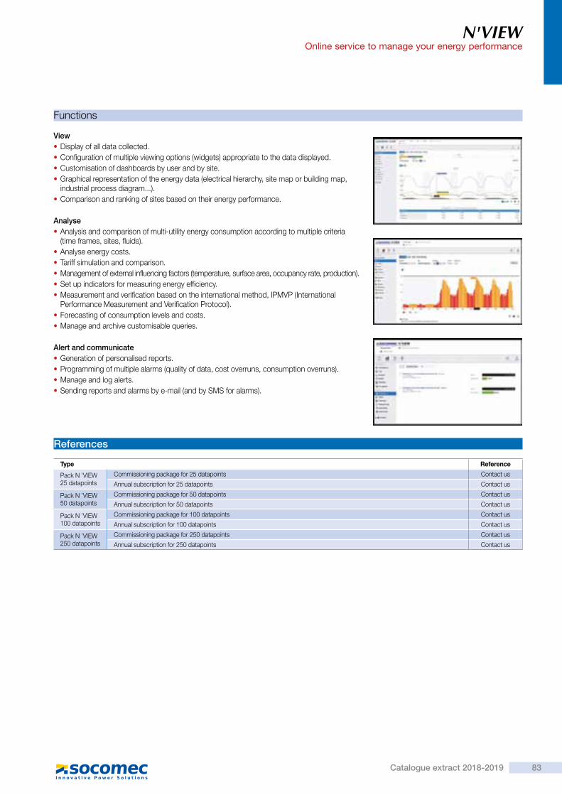
So
ftw
are
suit
e
soft_
043_
a_1_
x_ca
t
N'VIEWOnline service to manage your energy performance
Function
The N’VIEW online service offers easy and intuitive analysis of energy consumption regardless of the business sector (industry, building, infrastructure…).Compatible with the main market communication gateways including Socomec devices (DIRIS G, DIRIS Digiware D-70 and DATALOG H80 / 81), N’VIEW platform ensures that multi-utility data is collected.
From the identification of potential energy savings to long-term performance tracking and investment validation, N’VIEW offers a complete package of services for efficient energy management.To meet specific requirements, the N’VIEW platform can also interface with other energy management applications (Energy Apps) which are already available or can be created on demand.
Advantages
Easy to useCloud-based hosting on a scalable and secure platform ensures the project is easily implemented, and offers great flexibility with an N'VIEW subscription.Eliminates technical infrastructure problems, leaving the customer free to focus on management of energy performance.
Multi-user accessThe N'VIEW service appeals to stakeholders directly involved in energy performance, such as Energy Managers and technical users. It also provides services to help the management team define the energy strategy, and to help management controllers optimise and allocate energy spending.
Various functionsThe N’VIEW service provides a wide range of functions for the monitoring of measurements, the analysis of energy consumption levels and the management of costs. All these features are part of a continuous improvement plan for energy performance, as defined in standard ISO 50001.
> Easy to use > Multi-user access > Various functions
Strong points
> Industry > Building > Infrastructure > Local authority
The solution for
N'VIEWOnline service to manage your energy performance
Type Reference
Pack N ’VIEW 25 datapoints
Commissioning package for 25 datapoints Contact us
Annual subscription for 25 datapoints Contact us
Pack N ’VIEW 50 datapoints
Commissioning package for 50 datapoints Contact us
Annual subscription for 50 datapoints Contact us
Pack N ’VIEW 100 datapoints
Commissioning package for 100 datapoints Contact us
Annual subscription for 100 datapoints Contact us
Pack N ’VIEW 250 datapoints
Commissioning package for 250 datapoints Contact us
Annual subscription for 250 datapoints Contact us
References
View • Display of all data collected. • Configuration of multiple viewing options (widgets) appropriate to the data displayed. • Customisation of dashboards by user and by site. • Graphical representation of the energy data (electrical hierarchy, site map or building map, industrial process diagram...).
• Comparison and ranking of sites based on their energy performance.
Analyse • Analysis and comparison of multi-utility energy consumption according to multiple criteria (time frames, sites, fluids).
• Analyse energy costs. • Tariff simulation and comparison. • Management of external influencing factors (temperature, surface area, occupancy rate, production). • Set up indicators for measuring energy efficiency. • Measurement and verification based on the international method, IPMVP (International Performance Measurement and Verification Protocol).
• Forecasting of consumption levels and costs. • Manage and archive customisable queries.
Alert and communicate • Generation of personalised reports. • Programming of multiple alarms (quality of data, cost overruns, consumption overruns). • Manage and log alerts. • Sending reports and alarms by e-mail (and by SMS for alarms).
Functions
83Catalogue extract 2018-2019
References Pages References Pages References Pages References Pages
References list
4825 0080 754825 0082 754825 0083 754825 0088 71, 754825 0089 71, 754825 009x 714825 02xx 714825 0400 794825 0401 794825 0402 754825 0403 714825 0404 714825 0405 714825 0406 714825 0500 654825 0501 65, 834825 0502 654826 0100 214829 0050 29, 31, 35, 39, 51, 55, 614829 0101 294829 0102 31
4829 0103 294829 0105 314829 0106 314829 011x 394829 0120 294829 0128 394829 0129 394829 013x 394829 014x 614829 0150 514829 0151 514829 0153 514829 0154 514829 0155 514829 0156 554829 0157 554829 016x 354829 0180 29, 31, 35, 39, 51, 55, 614829 0181 29, 31, 35, 39, 51, 55, 614829 0182 29, 31, 35, 39, 51, 55, 614829 0183 29, 31, 35, 39, 51, 55, 61
4829 0184 29, 31, 35, 39, 51, 55, 614829 0185 29, 31, 35, 39, 51, 55, 614829 0186 29, 31, 35, 39, 51, 55, 614829 0187 29, 31, 35, 39, 51, 55, 614829 0188 29, 31, 35, 39, 51, 55, 614829 0189 35, 51, 554829 0195 354829 0196 354829 0199 294829 0200 294829 0201 294829 0202 29, 834829 03xx 834829 050x 434829 055x 454829 057x 474829 058x 43, 45, 474829 0590 43, 45, 474829 0591 43, 45, 474829 0592 43, 45, 474829 0593 43, 45, 47
4829 0594 43, 45, 47
4829 0595 43, 45, 47
4829 0596 43, 45, 47
4829 0597 43, 45, 47
4829 0598 43
4829 0599 43
4829 0600 43, 47
4829 0601 43, 45, 47
4829 0602 43, 45, 47
4829 0603 43, 45, 47
4829 0605 39
4829 065x 45
4829 07xx 55
485x xxxx 83
4899 0011 71
5601 0017 29, 71, 75, 79
5601 0018 31, 71, 75, 79
6012 0000 29, 31, 71, 75, 79
84 Catalogue extract 2018-2019

Note
85Catalogue extract 2018-2019

Note
86 Catalogue extract 2018-2019

Model: SOCOMECProduction: SOCOMECPhotography: Martin Bernhart and Studio ObjectifPrinting:

Réf
: DC
G 1
9401
3i -
05/
18
Socomec: our innovations supporting your energy performance
The specialist for critical applications
Your power management expert
10 % of sales revenue dedicated to R&D
•Energy quality•Energy availability•Energy storage
400 experts dedicated to service provision
• Prevention and repairs•Measurement and analysis•Optimisation• Consultancy, commissioning
and training
1 independent manufacturer
• Control, command of LV facilities
•Safety of persons and assets
3,200 employees worldwide
• Measurement of electrical parameters
•Energy management
A worldwide presence
80 countries where our brand is distributed
8 production sites•France (x3)•Italy•Tunisia•India•China (x2)
27 subsidiaries•Australia•Belgium•China•France•Germany•India•Italy•Netherlands•Poland•Romania•Singapore •Slovenia•Spain•Switzerland•Thailand•Tunisia•Turkey•UK•USA
POwER switChing
POwER mOnitORing
POwER COnvERsiOn
ExPERt sERviCEs
HEAD OFFICE
SOCOMEC GROUPSAS SOCOMEC capital 10 633 100 €R.C.S. Strasbourg B 548 500 149 B.P. 60010 - 1, rue de Westhouse F-67235 Benfeld CedexTel. +33 3 88 57 41 41 - Fax +33 3 88 57 78 [email protected]
YOUR DISTRIBUTOR / PARTnER
www.socomec.com
Noncontractualdocum
ent.©2018,Socom
ecSAS.Allrightsreserved.-Docum
entprintedonpaperfrom
sustainablymanagedforests.
Top Related