


Languages
Pages
Legal

NEW JERSEY'S FIRST RESOURCE RECOVERY
FACILITY
(The Warren County Energy Resource Facility)
WOLFRAM G. SCHUETZENDUEBEL AND WILLIAM C. NOBLES Blount Energy Resource Corp.
Montgomery, Alabama
ABSTRACf
New Jersey's first waste-to-energy facility has been constructed in Oxford Township, New Jersey, and has been in operation since June, 1988. This paper provides a detailed description of the Warren County Energy Resource Facility, its major process systems and poststartup design modifications. Certain aspects of the
,plant design philosophy are also described.
INTRODUCfION
The Pollution Control Financing Authority of Warren County, New Jersey formulated a long-range Waste Management Plan to comply with a mandate established by the New Jersey legislature. This plan called for the construction of a 400 TPD resource recovery facility to serve the population of 584,500 in the Warren County area. A flow control plan was established that directs the anticipated 94,660 TPY of MSW to the resource recovery facility. In addition, a sanitary landfill has been constructed adjacent to the facility to receive the residue from the facility as well as bypassed MSW, and unprocessible or unacceptable waste. The landfill also accepts small private loads of refuse, eliminating the need for a public dumping station at the facility.
321
The Pollution Control Financing Authority has negotiated contracts for the supply of additional refuse to the facility from adjacent counties to assure full capacity of the facility.
In June 1 985, the County of Warren contracted with BERC to design, build and operate their resource recovery facility. Under the contract, the facility was to guarantee the annual processing capacity of 1 1 6,800 tons of MSW with a design heating value of 5300 Btul lb (HHV), whereas the reference fuel heating value of the fuel, upon which all guarantees are based, is 4500 Btu/lb (HHV).
An ultimate analysis of the design fuel is presented in Table 1 . Of interest is the relatively high sulfur content in the fuel analysis supplied by the County.
GENERAL PLANT DESCRIPTION
The plant consists of two independent processing trains with a nominal capacity of 200 TPD each, based upon the design fuel. This allows for combusting the guaranteed amount of MSW with an 80% plant availability.
The higher anticipated availability, in addition to the design conservatism, permits this facility to process significantly larger amounts of reference MSW, or MSW with higher calorific values, provided that the
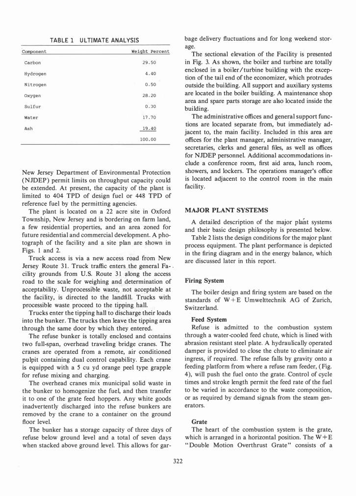
TABLE 1 ULTIMATE ANALYSIS Component Weight Percent
Carbon 29.50
Hydrogen 4.40
Nitrogen 0.50
Oxygen 28.20
Sulfur 0.30
Water 17.70
Ash 19.40
100.00
New Jersey Department of Environmental Protection (NJDEP) permit limits on throughput capacity could be extended. At present, the capacity of the plant is limited to 404 TPD of design fuel or 448 TPD of reference fuel by the permitting agencies.
The plant is located on a 22 acre site in Oxford Township, New Jersey and is bordering on farm land, a few residential properties, and an area zoned for future residential and commercial development. A photograph of the facility and a site plan are shown in Figs. 1 and 2.
Truck access is via a new access road from New Jersey Route 3 1 . Truck traffic enters the general Fa- . cility grounds from U.S. Route 3 1 along the access road to the scale for weighing and determination of acceptability. Unprocessible waste, not acceptable at the facility, is directed to the landfill. Trucks with processible waste proceed to the tipping hall.
Trucks enter the tipping hall to discharge their loads into the bunker. The trucks then leave the tipping area through the same door by which they entered.
The refuse bunker is totally enclosed and contains two full-span, overhead traveling bridge cranes. The cranes are operated from a remote, air conditioned pulpit containing dual control capability. Each crane is equipped with a 5 cu yd orange peel type grapple for refuse mixing and charging.
The overhead cranes mix municipal solid waste in the bunker to homogenize the fuel, and then transfer it to one of the grate feed hoppers. Any white goods inadvertently discharged into the refuse bunkers are removed by the crane to a container on the ground floor level.
The bunker has a storage capacity of three days of refuse below ground level and a total of seven days when stacked above ground level. This allows for gar-
322
bage delivery fluctuations and for long weekend storage.
The sectional elevation of the Facility is presented in Fig. 3. As shown, the boiler and turbine are totally enclosed in a boiler I turbine building with the exception of the tail end of the economizer, which protrudes outside the building. All support and auxiliary systems are located in the boiler building. A maintenance shop area and spare parts storage are also located inside the building.
The administrative offices and general support functions are located separate from, but immediately adjacent to, the main facility. Included in this area are offices for the plant manager, administrative manager, secretaries, clerks and general files, as well as offices for NJDEP personnel. Additional accommodations include a conference room, first aid area, lunch room, showers, and lockers. The operations manager's office is located adj acent to the control room in the main facility.
MAJOR PLANT SYSTEMS
A detailed description of the major plant systems and their basic design philosophy is presented below.
Table 2 lists the design conditions for the major plant process equipment. The plant performance is depicted in the firing diagram and in the energy balance, which are discussed later in this report.
Firing System
The boiler design and firing system are based on the standards of W + E Umwelttechnik AG of Zurich, Switzerland.
Feed System
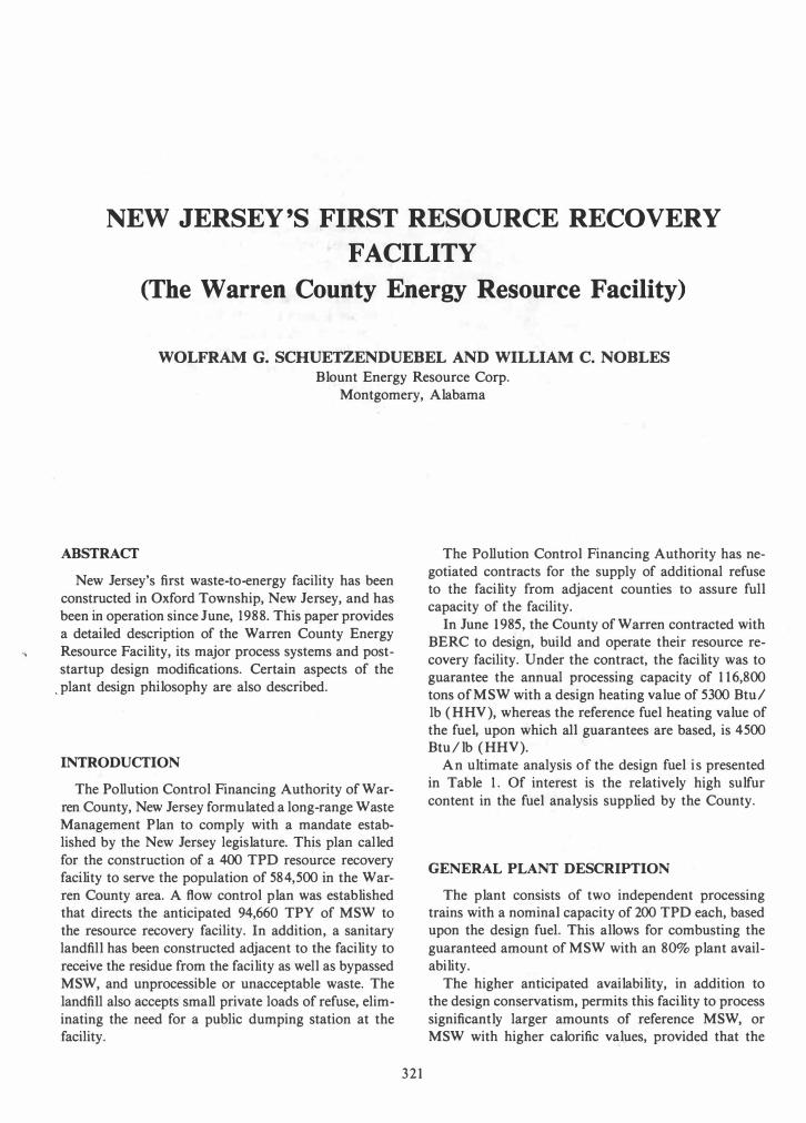
Refuse is admitted to the combustion system through a water-cooled feed chute, which is lined with abrasion resistant steel plate. A hydraulically operated damper is provided to close the chute to eliminate air ingress, if required. The refuse falls by gravity onto a feeding platform from where a refuse ram feeder, (Fig. 4), will push the fuel onto the grate. Control of cycle times and stroke length permit the feed rate of the fuel to be varied in accordance to the waste composition, or as required by demand signals from the steam generators.
Grate
The heart of the combustion system is the grate, which is arranged in a horizontal position. The W + E "Double Motion Overthrust Grate" consists of a

323

z <t ....I a.. LIJ l-v; � Z
• ::::I 0 r (..) Z LIJ 0:: 0:: <t � N (.!J t:i:
+ +
324

�I r�·� .
I �I 1
L __ _ _
325
�--�---
i - -.- � � � - -. - � � - �
J - - - - �
L _
- . -.-.-----�---.-g -�---.-.- _. �·I · l
z o t= <C > I.&J -l I.&J -l <C z o t= u I.&J Vl
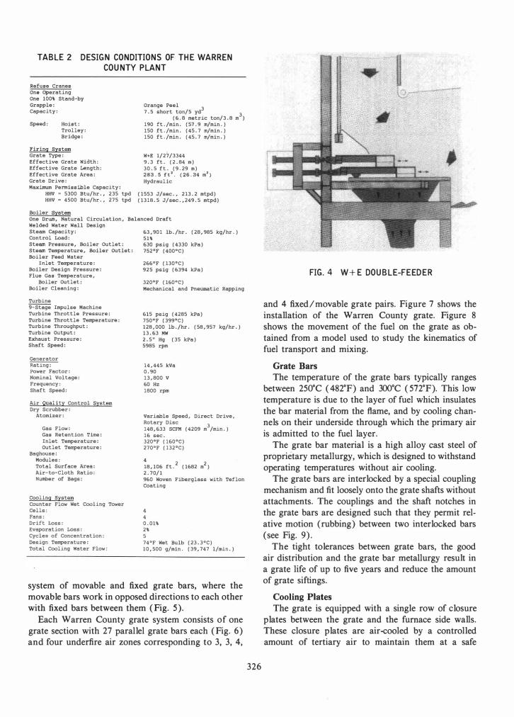
TABLE 2 DESIGN CONDITIONS OF THE WARREN COUNTY PLANT
Refuse Cranes One Operating One 100\ Stand-by Grapple: Capacity:
Speed: Hoist: Trolley: Bridge:
Firing System Grate Type: Effective Grate Width: Effective Grate Length: Effective Grate Area: Grate Drive: Maximum Permissible Capacity:
HHV • 5300 Btu/hr., 235 tpd HHV = 4500 Btu/hr., 275 tpd
Boiler System
Orange Peel 3
7.5 short ton/5 yd 3
(6.8 metric ton/3.8 m ) 190 ft./min. (57.9 m/min.) 150 ft./min. (45.7 m/min.) 150 ft./min. (45.7 m/min.)
W+E 1/27/3344 9.3 ft. (2.84 m) 30.5 ft. (9.29 m) 283.5 ft'. (26.34 m') Hydraulic
(1553 J/sec., 213.2 mtpd) (1318.5 J/sec. ,249.5 mtpd)
One Drum, Natural Circulation, Balanced Draft Welded Water Wall Design Steam Capacity: Control Load: Steam Pressure, Boiler Outlet: Steam Temperature, Boiler Outlet: Boiler Feed water
Inlet Temperature: Boiler Design Pressure: Flue Gas Temperature,
Boiler OUtlet: Boiler Cleaning:
Turbine 9-Stsge Impulse Machine Turbine Throttle Pressure: Turbine Throttle Temperature: Turbine Throughput: Turbine output: Exhaust Pressure: Shaf t Speed:
Generator Rating: Power Factor: Nominal Vol tege: Frequency: Shaft Speed:
Air Quality Control System Dry Scrubber:
Atomizer:
Gas Flow: Gas Retention Time: Inlet Temperature: Outlet Temperature:
Baghouse: Modules: Total Surface Area: Air-to-Cloth Ratio: Number of Bags:
Cooling System Counter Flow Wet Cooling Tower Cells: Fans: Drift Loss: Evaporation Loss: Cycles of Concentration: Design Temperature: Total Cooling water Flow:
63,901 lb./hr. (28,985 kg/hr.) 51\ 630 psig (4330 kPa) 752°F (400°C)
266°F (130°C) 925 psig (6394 kPa)
320°F (160°C) Mechanical and Pneumatic Rapping
615 psig (4285 kPa) 750°F (399°C) 128,000 lb./hr. (58,957 kg/hr.) 13.63 MW 2.5" Hg (35 kPa) 5985 rpm
14,445 kVa 0.90 13,800 V 60 Hz 1800 rpm
Variable Speed, Direct Drive, Rotary Disc
3 148,633 SCFII (4209 m /min.) 16 sec. 320°F (160°C) 270°F (132°C)
4 18,106 ft.
2 (1682 m
2)
2.70/1 960 Woven Fiberglass with Teflon Coating
4 0.01\ 2\ 5 74°F Wet Bulb (23.3°C) 10,500 g/min. (39,747 l/min.)
system of movable and fixed grate bars, where the movable bars work in opposed directions to each other with fixed bars between them (Fig. 5).
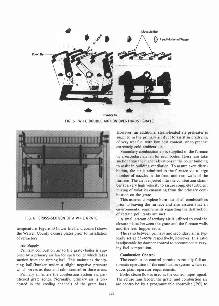
Each Warren County grate system consists of one grate section with 27 parallel grate bars each (Fig. 6) and four underfire air zones corresponding to 3, 3, 4,
326
FIG. 4 W+E DOUBLE-FEEDER
and 4 fixed/movable grate pairs. Figure 7 shows the installation of the Warren County grate. Figure 8 shows the movement of the fuel on the grate as obtained from a model used to study the kinematics of fuel transport and mixing.
Grate Bars
The temperature of the grate bars typically ranges between 250°C (482°F) and 300°C (572°F). This low temperature is due to the layer of fuel which insulates the bar material from the flame, and by cooling channels on their underside through which the primary air is admitted to the fuel layer.
The grate bar material is a high alloy cast steel of proprietary metallurgy, which is designed to withstand operating temperatures without air cooling.
The grate bars are interlocked by a special coupling mechanism and fit loosely onto the grate shafts without attachments. The couplings and the shaft notches in the grate bars are designed such that they permit relative motion (rubbing) between two interlocked bars (see Fig. 9).
The tight tolerances between grate bars, the good air distribution and the grate bar metallurgy result in a grate life of up to five years and reduce the amount of grate siftings.
Cooling Plates
The grate is equipped with a single row of closure plates between the grate and the furnace side walls. These closure plates are air-cooled by a controlled amount of tertiary air to maintain them at a safe
Movable Bar
o Feed Motion of Waste
Fixed Bar ---:: ........ -:
---------
PrimaryAlr FIG. 5 W+E DOUBLE MOTION OVERTHRUST GRATE
FIG.6 CROSS-SECTION OF A W+E GRATE
temperature. Figure 10 (lower left-hand comer) shows the Warren County closure plates prior to installation of refractory.
Air Supply
Primary combustion air to the grate/boiler is supplied by a primary air fan for each boiler which takes suction from the tipping hall. This maintains the tipping hall/bunker under a slight negative pressure which serves as dust and odor control in these areas.
Primary air enters the combustion system via partitioned grate zones. Normally, primary air is preheated in the cooling channels of the grate bars.
327
However, an additional steam-heated air preheater is supplied in the primary air duct to assist in predrying of very wet fuel with low heat content, or to preheat extremely cold ambient air.
Secondary combustion air is supplied to the furnace by a secondary air fan for each boiler. These fans take suction from the higher elevations in the boiler building to assist in building ventilation. To assure even distribution, the air is admitted to the furnace via a large number of nozzles in the front and rear walls of the furnace. The air is injected into the combustion chamber at a very high velocity to assure complete turbulent mixing of volatiles emanating from the primary combustion on the grate.
This assures complete bum-out of all combustibles prior to leaving the furnace and also assures that all environmental requirements regarding the destruction of certain pollutants are met.
A small stream of tertiary air is utilized to cool the closure plates between the grate and the furnace walls and the feed hopper table.
The ratio between primary and secondary air is typically set at 55-45% respectively; however, this ratio is adjustable by damper control to accommodate varying fuel composition.
Combustion Control
The combustion control permits essentially full automatic operation of the combustion system which reduces plant operator requirements.
Boiler steam flow is used as the control input signal. The refuse ram feeder, the grate, and combustion air are controlled by a programmable controller (PC) to
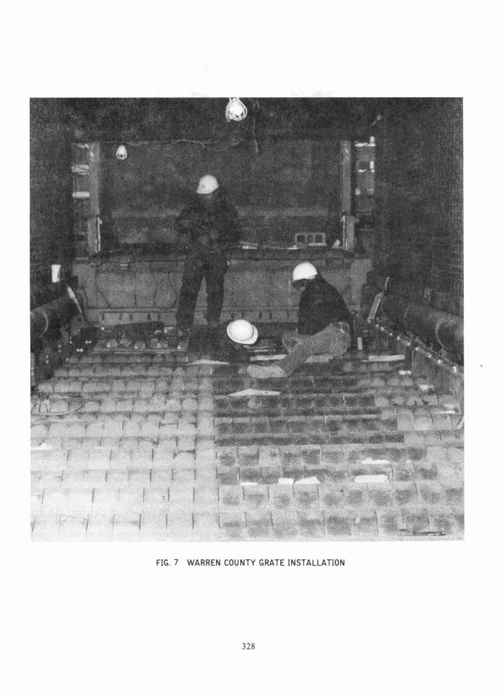
FIG. 7 WARREN COUNTY GRATE INSTALLATION
328

1
3
2
4
FIG.8 FUEL KINEMATICS ON A W+E GRATE
FIG. 9 W+E GRATE BAR
329
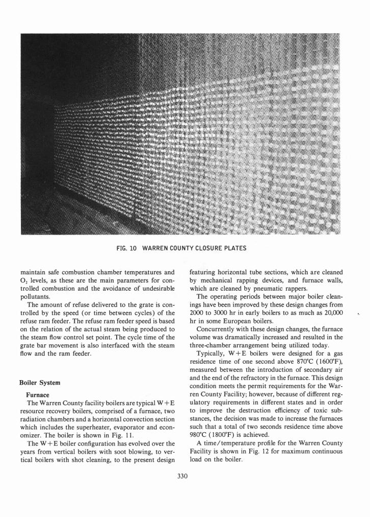
FIG. 10 WARREN COUNTY CLOSURE PLATES
maintain safe combustion chamber temperatures and O2 levels, as these are the main parameters for controlled combustion and the avoidance of undesirable pollutants.
The amount of refuse delivered to the grate is controlled by the speed (or time between cycles) of the refuse ram feeder. The refuse ram feeder speed is based on the relation of the actual steam being produced to the steam flow control set point. The cycle time of the grate bar movement is also interfaced with the steam flow and the ram feeder.
Boiler System
Furnace
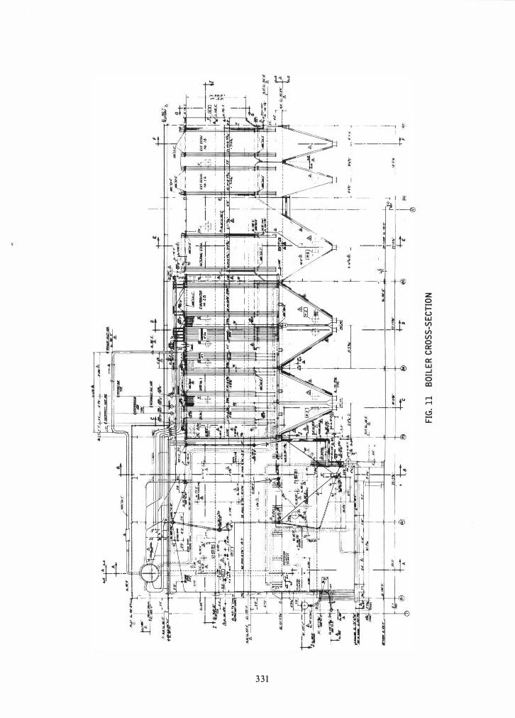
The Warren County facility boilers are typical W + E resource recovery boilers, comprised of a furnace, two radiation chambers and a horizontal convection section which includes the superheater, evaporator and economizer. The boiler is shown in Fig. 1 1 .
The W + E boiler configuration has evolved over the years from vertical boilers with soot blowing, to vertical boilers with shot cleaning, to the present design
330
featuring horizontal tube sections, which are cleaned by mechanical rapping devices, and furnace walls, which are cleaned by pneumatic rappers.
The operating periods between major boiler cleanings have been improved by these design changes from 2000 to 3000 hr in early boilers to as much as 20,000 hr in some European boilers.
Concurrently with these design changes, the furnace volume was dramatically increased and resulted in the three-chamber arrangement being utilized today.
Typically, W + E boilers were designed for a gas residence time of one second above 870·C (1 600·F), measured between the introduction of secondary air and the end of the refractory in the furnace. This design condition meets the permit requirements for the Warren County Facility; however, because of different regulatory requirements in different states and in order to improve the destruction efficiency of toxic substances, the decision was made to increase the furnaces such that a total of two seconds residence time above 980·C (1 800·F) is achieved.
A time/temperature profile for the Warren County Facility is shown in Fig. 1 2 for maximum continuous load on the boiler.
331
z o j:: u UJ VI
I VI VI o c::: u c::: UJ ...J (5 aJ

CONTROL TEf1P. (1600° F)
WARREN COUNTY NEW JERSEY RESOURCE RECOVERY FACILITY
TIME - TEMPERATURE PROFILE
(COMBUSTION/RADIATION CHAr1BER)
ESTIMATED FOR 100% BOILER LO�D CONDITION
FUEL (HHV) = 5300 Btu/lb MSW, EXCESS AIR = 120%
LIMIT OF REFRACTORY 1--.,---,..--( 2
SECONDARY AIR
TEMPERATURE
24 ft
9 ft 2.2 sec
33 ft 1. 9 sec
TEMPERATURE
2B ft 2.0 sec
c:!» 2000°F (FLAME TEMPERATURE)
c:i) 1650°F (LIMIT OF REFRACTORY)
� 1600°F (CONTROL TEMPERATURE)
G) Q CD
1500°F (END OF FURNACE)
1350°F
1200�F (ENTRANCE TO CONVECTION SECTION)
FIG. 12 TIME/TEMPERATURE PROFILE
332

Performance
The design conditions for the boiler are based on the maximum firing capability of the grate (see Firing Diagram, Fig. 13) and its resulting heat release, from combusting 8505 kg/h (1 8,750 lb/hr) of fuel with a higher heating value of 1 336 kcallkg (5300 Btu/lb). The resultant sensible heat supplied to the boiler is approximately 21 .7 X 106 kcal/h (86 X 106 Btu/hr) from which approximately 29,000 kg/h (64,000 lb/ hr) of superheated steam at 400°C (752°F) and 4.3 X 10⁶ Pascals (630 psig) are generated.
The design pressure of the boiler pressure parts is 6.3 X 10⁶ Pascals (925 psig).
Demineralized and deaerated feed water is supplied to the boiler at 1 30°C (266°F).
The control load point of the boiler was selected at about 14,970 kg/h (33,000 lb/hr) steam flow, or 5 1 % of the boiler maximum rating. This selection results in an attemperator flow of 907 kg/h (2000 lb/hr) to reduce the final superheater inlet temperature from 350°C (660°F) to 320°C (60rF) to maintain the 400°C (752°F) boiler outlet steam temperature. On the gas side, the temperature under maximum operating conditions and based upon 1 00% excess air are as follows:
Furnace, end of refractory = 980°C (1 800°F)
Superheater inlet = 680° (1255°F)
Economizer outlet = 1 60°C (320°F)
The resulting boiler efficiency was predicted to be 75%.
Heating Surface
The boiler is equipped with welded waterwalls in the furnace, the radiation chambers and the convection section side walls, except for the economizer section. Here the gas temperature is too low to justify the expense of waterwalls. The roof is also water cooled. The superheater consists of a final and an initial superheater with a spray desuperheating station between the two sections. The final superheater is arranged in parallel flow with the gas in order to reduce the tube temperatures for corrosion protection. All other surfaces are arranged in counter flow. In the direction of the gas flow, the superheater is followed by two evaporator bundles and a final economizer bundle and two external economizer bundles.
Provisions are made to bypass the external two economizer bundles during start-up, shut-down, low-load operation, or operation with feedwater heaters out of service to avoid falling below the dew point in the tail end of the boiler with l�w feedwater temperature.
333
IIIW 0 ' VAIlIOUI .. IATI 0 ' COIIIUITION
�11I'OIlIlANCI INVlLO�1
100
�IAK LOAD � �III"IATIO II.NOI It ITUII
• / - --7-- Z z ,-- I ;0 / I .. • • 10
/ I ! / 1 I
4 / I
.. C 1M Z
I I I I I
: 7 .. c ... � .. ... c ..
I
I 7 . . 10 T,,"oua"-�UT �III COII.UITION TIIAIN
(TON/HIII
IIIW:IIUNICI�.L 10LIO WAITI
H".:HlaHIll .. IATIOIO YALUI
FIG. 13 COMBUSTION TRAIN PERFORMANCE
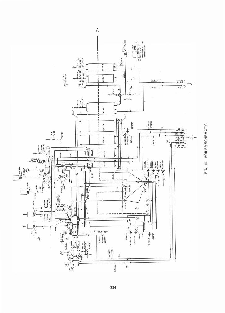
A flow-schematic of the boiler is presented in Fig. 14.
Tube materials are all low-carbon steel with the exception of the final superheater which is T - 1 1 material for corrosion protection.
The wall thicknesses selected for all boiler tubes include a significant corrosion allowance.
Cleaning System
The boilers are designed for on-line cleaning by mechanically rapping the vertical tubes of the convection sections and pneumatically rapping sections of the welded furnace walls, the roof area, and arches. To this end, the lower header of the pendant tube sections is equipped with an impact shaft, which is hit by a free falling hammer rotating on a motor driven shaft alongside the boiler walls (Fig. 1 5). Multiple hammers are located on a single shaft impacting on sequential headers in a predetermined sequence. Acceleration of the headers and tubes up to about 1 00 g are achieved, which cause the deposits to slide off the tube in a
w
w
�
.. '
",
''':::'' �Tt �
, �t _-,
; .•. __
,�
--
. ,
I ...
".:"
I '.-
"
, e�
r - ""-�
r - "" ��::.. -
"'::" �
a::::]
¥f.=:
�'
I -
--
. .
'"
.. ,
I: /=
� i
r.. .•
1'r-'CF
If-.JI)
�.,.
1�-I/Jl1
I·n �
I_ I�"'IIJIW
'''�_
/ I",:
, 1i
illi:Et
.--
--
--
--
I •
I I
I I
I I
I I
I I
I I
I I
1 ,1u(
.-
-----I I I
+1: (i
: i I I o
� \)
�
"
""-.
FIG.
14
BOIL
ER S
CHEM
ATIC
A' ··-
·· �
/· t. __
."
.�t.I:
:
---c;>
• I
I l><Ho
o1
� ! I ce=
I "
� •
t""","a,
,,�
,..
<>
�I I�
'& &!
I· .,
... L
T-,
1
:- � ";.
.:oo - ; ' I
�-T
-. .:.tkJ;'; --'
- -i 1�
' :�'�
:"!"I!�
�J __
: ntS
'IN..'15:
WIU. BE
90FPE
D LOO
SE

FIG. 15 MECHANICAL RAPPER SYSTEM
fashion similar to that experienced with electrostatic precipitator rapping systems. The frequency of the rapping cycles, which is a function of the fuel quality, is adjustable.
On the furnace walls, roof, and arches, pneumatic rapping devices are used because of the various required elevations. Here, pneumatically caused acceleration acts upon an impact plate, which is mounted to a number of waterwall tubes (Fig. 1 6). The cycle for the pneumatic rappers is also controllable as a function of furnace deposit build-up.
Auxiliary Burners
Each boiler is equipped with two auxiliary oil-fired burners in compliance with NJDEP permit conditions. The burners are sized to start-up a cold boiler and bring it up to 1 800°F at the end of the furnace refractory. According to the permit, MSW charging may not begin, unless a 1 500°F temperature level is reached one second downstream of secondary air injection. Oil firing is maintained until stable MSW combustion is achieved. After that, the burners are shut down and only restarted if the control temperature in the furnace falls below 1600°F.
The burners are equipped with their own air fans, as the high velocity secondary air could possibly cause a flame-out. The burners are withdrawn from the furnace, and the burner openings in the furnace wall are
335
FIG. 16 PNEUMATIC RAPPER SYSTEM
closed by a refractory lined guillotine type closure when the burners are not in operation.
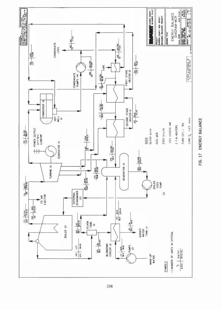
The Turbine Cycle
The overall turbine cycle is depicted schematically in the energy balance diagram (Fig. 1 7) and represents the predicted plant performance under maximum load conditions.
Steam is conveyed to the turbine-generator via a common main steam line. The turbine-generator is a nominal 1 3 MW Westinghouse impulse type machine with a gear-driven Brush generator rated at 14,445 kV A. The turbine, which has a total of nine stages and 30.5 cm (12 in.) long last stage blades, is equipped with four uncontrolled extraction ports for supply of steam to the two low pressure feed water heaters and the deaerator. Additional plant auxiliary requirements are also supplied from extraction steam, if needed.
The turbine exhausts into a main condenser, which is maintained at 63.5 mm (2X in. ) Hg back pressure by a water cooling system. The plant is equipped with a bypass condenser, which permits full boiler operation during turbine outage. In this case, pressure and temperature reduction takes place prior to admitting the steam to the bypass condenser. A four-cell cooling tower provides for plant cooling, including operation in the bypass mode . .
The condensate pumps are sized to take suction from either the main or bypass condenser. Two condensate pumps are provided, sized for 1 00% flow each. Three feedwater pumps are sized for 65% of total plant flow each. There are two motor-driven and one turbinedriven feed pumps.
A make-up water treatment system and a split flow
v.>
v.>
0\
495
1.124
650
481.90
205
I ..
3IXI
2-33:'
"
BLO
WD
OW
N
COO
LER
(1) _
r �-
I
10 1
,.30
38.'
I 38."
PUN
PS
(2)
WA
KE-U
P W
AT
ER
SYW
BOLS
',52
112.43
.
�
BOIL
ER (
2)
80 I
811 'SO I
1378 .9
3 H
. 615
,.3 -T,.30
38.'
1130.s
o
38.< I
'8.15
QUE
NCH
W
AT
ER
TA
NK (
I)
( )
NU
WB
ER
OF
UNIT
S IN
SY
STEW
.
OF
Ibs
/h
r p
slo
BT
U/lb
.
H.
I ... "
� 113
78.93
TO
AIR
EJ
ECT
OR
TU
RBI
NE (
I)
109 I
95.185
L2l
T ..
.. 91
PO
WER
O
UTP
UT
ef
f=
81
%
1I.9
88M
I'I
� G
ENER
AT
OR
(I)
I EXT
ERN
AL
""""'"
I ,�
(2
)
1079.11
270 1
.. 35
1 39J8
\'7L
4'
COND
ENSE
R (I)
HOTL
W
ELL
(I) 113
4'.
9 104
.780
>40.95
COND
ENSA
TE
PUN
PS
(4) 10'3
1 fO"
"l
H'
I 104
.180
10.
I SOO
L2lJ
76M
CON
DEN
SAT
E LO
SS 10.
I Rig
10
\ 11.
0'
105.5 �
I
7.04
59 .•
16:98
SJ
AE
f--
DE
AER
AT
OR
(I)
200
10<.78
0 la
.. 173
.9"
J
+ J I P
IJ �.
,� IL.
L{)--
(3)
BO
ILER
F
EED
PU
I.IP
205
1,3.5
58 la."
--1233
...
I SECO
ND
ST
AG
E t
HEA
TER
(I)
183..
.bo..
8 I
150.02
BA
SIS
112
.43
4
Ib/
hr
100
%
NCR
53
00
b
tu/
lb
122%
EXCE
SS
AIR
2 F.
W. H
EAT
ERS
TU
RB
EFF
. =
81%
eOND
PB
=
1.2
3
psi a
FIG. 1
7 EN
ERGY
BAL
ANCE
FIR
ST
STA
GE
HEA
TER
(I)
10.1
9Ot.
illT16
,8i
ALfR
ED W
. ENT
OIWAN
JR.
N.J. L
ICENS
E NO
.11663
1 .... -��
�.1
II�� COUN
TY f€
. JE
RSEY
RESOUfIC[
RECO
VERY
PROJECT
ORA
WMi T
IlLE
ENER
GY B
ALAN
CE II
DIAG
RAM-
MCR
� NOHE
D,UL
01' ..
.. 15
I
I ....... DOClI
IS.OOC. I ..
000. II
!f�..=.
.l'=Y.
8�
06
9
l-..etooO.
_ ...
1""1
_ ._
1 WC
-OI-0
2-01-
B 2
I. (' ... 'rOIl Inc1neratou 2. Oryn Out let ea ... ), .. ,hou .. Out let ca ... 4. '.bble LiM S. Proce •• Water 6. Shker Water 7. Dilution Water 8. Shked LIM 9. 1.1 .. Grit
llf1:
SilO
-!-.FIlER
,
INC [f<RAlOR -0- ----;:::::=::;� <>"5£5
. CP..F.S
10. feed Pu.p Oi.char.e II. 'eed Slurry to Dryer
GRfNllY
12. Feed Slurry aecirculated I). Drye .. rnction 14 . ... hou.e 'uctlon IS. Tot.l Powder To Oiapo .. l
L I f"'C F"[[OCR -/,
. ---
,
,
*+---' 0 '-----'
L I 1"'£ SLR<£R
, G?IT TO
DISPOSA.
LII"'£ TFN< F"EED TFf'1<
J. D. r""
FIG. 18 AQCS SCHEMATIC
demineralizer system are provided. Boiler feedwater treatment to ABMA specifications is accomplished by phosphate treatment and oxygen scavenging. The condensate system is protected by amine injection.
Make-up water, as well as all other plant water is supplied from two wells, close to the plant site, at the bank of the Pequest River.
Air Quality Control System
Permit Conditions The plant was initially designed for a sulfur removal
capability of 70%, based upon a sulfur content of 0.3% in the design fuel. HCI removal was required to be 80% and particulate emissions were initially restricted to 0.31 g/Nm3 (0.02 gr/dscf). However, because of a high influx of S02 from a nearby coal-fired power plant in Pennsylvania, the NJDEP decreed during the permitting process that the facility's gas cleaning equipment should be designed in accordance with LAER with respect to HCI and S02' and set the permitted emission levels as follows:
S02 = 80% removal or 50 ppmvl (not to exceed 100 ppmv) HCI = 90% removal or 50 ppmvl HF = 90% removal
Furthermore, since another facility in New Jersey, located in a nonattainment area for particulate emissions, had guaranteed not to exceed 0.015 gr / dscf, corrected to 7 % O2, the NJDEP required the Warren
I Whichever is least stringent; dry basis corrected to 7% 0,.
337
County Facility to meet the same particulate emission limits.
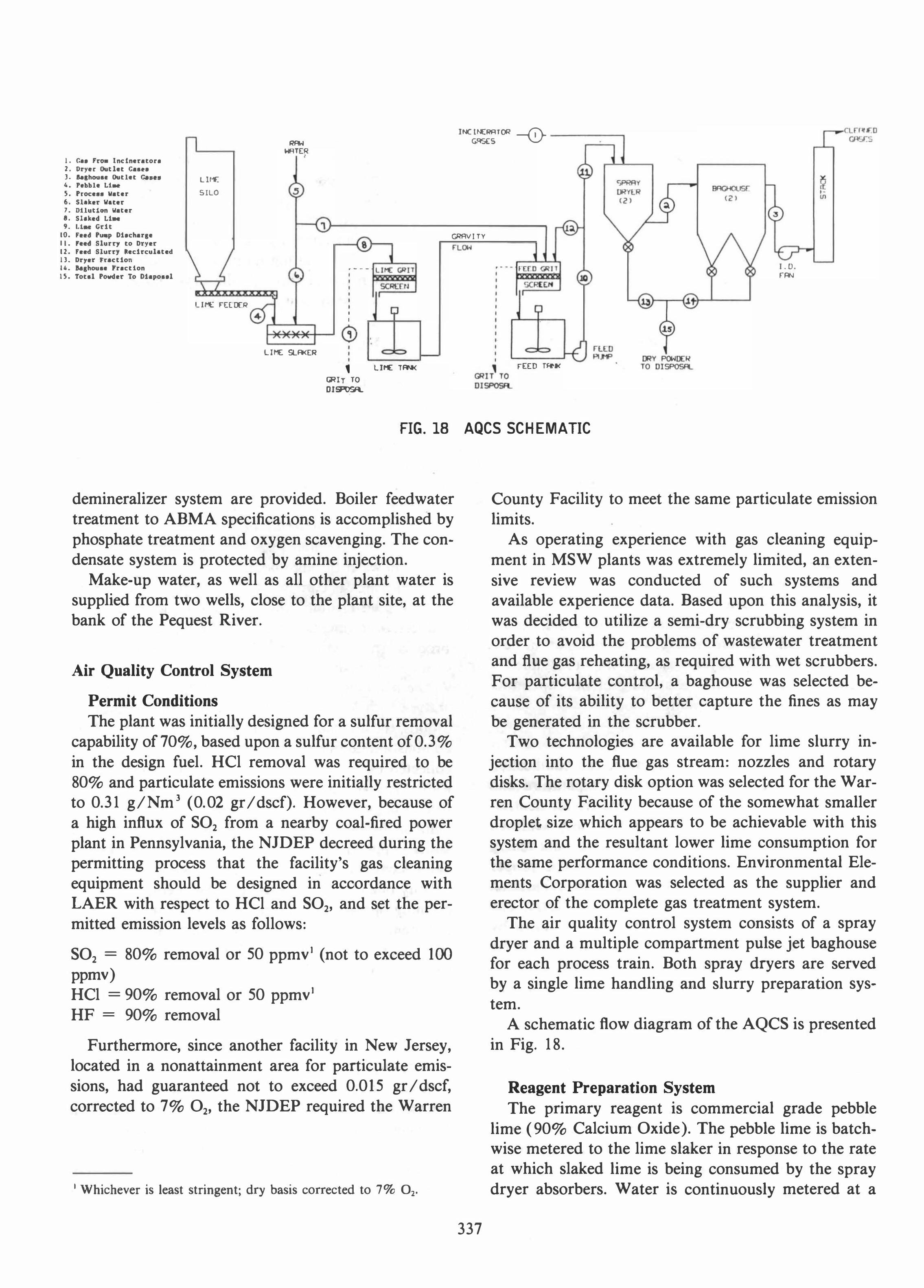
As operating experience with gas cleaning equipment in MSW plants was extremely limited, an extensive review was conducted of such systems and available experience data. Based upon this analysis, it was decided to utilize a semi-dry scrubbing system in order to avoid the problems of wastewater treatment and flue gas reheating, as required with wet scrubbers. For particulate control, a baghouse was selected because of its ability to better capture the fines as may be generated in the scrubber.
Two technologies are available for lime slurry injection into the flue gas stream: nozzles and rotary disks. The rotary disk option was selected for the Warren County Facility because of the somewhat smaller droplet size which appears to be achievable with this system and the resultant lower lime consumption for the same performance conditions. Environmental Elements Corporation was selected as the supplier and erector of the complete gas treatment system.
The air quality control system consists of a spray dryer and a multiple compartment pulse jet baghouse for each process train. Both spray dryers are served by a single lime handling and slurry preparation system.
A schematic flow diagram of the AQCS is presented in Fig. 18 .
Reagent Preparation System The primary reagent is commercial grade pebble
lime (90% Calcium Oxide). The pebble lime is batchwise metered to the lime slaker in response to the rate at which slaked lime is being consumed by the spray dryer absorbers. Water is continuously metered at a
fixed ratio to the rate of pebble lime being fed to the slaker. In order to produce the highest quality slaked lime, it is necessary to achieve high temperatures within the slaker. This is accomplished by maintaining a paste-like consistency of 43% solids in the slaker, which results in very high slaking temperatures. This high-solids lime slurry is sluiced to 20% solids by a pre-set water spray bar to enable gravity flow of the lime milk. The dilute slaked lime flows to a vibrating wire mesh screen for separation of grit and tramp material before entering the lime milk holding tank. The flow of pebble lime, slaking water and sluicing water are all turned on and off in response to the lime milk holding tank high and low level switches. The cycle time between high and low level is adjusted to achieve near continuous operation of the slaking system. The lime milk holding tank provides an inventory of high solids lime slurry. This concentrated lime slurry flows by gravity to the feed tanks for final dilution before being fed to the spray dryers.
The feed tank is a source of surge capacity for the lime feed pumps which draw suction from the tanks and deliver to the spray dryer absorber system. The concentration or percent solids of the lime milk slurry in this tank is either automatically or manually adjusted to maintain the desired stack emission of acid gases. Each spray dryer absorber has a completely dedicated pump station, consisting of one operating and one installed spare pump.
Spray Dryer
To achieve the required reaction, the combustion gases are cooled to a pre-selected temperature and contacted with the alkaline lime particles for neutralization of the acids. This is simultaneously achieved by intimately mixing the atomized lime milk slurry droplets and the hot combustion gases. The proper amount of lime is controlled in the feed preparation system by adjusting the density of the lime slurry. The proper amount of water for cooling is controlled by throttling the flow of slurry entering the spray dryer to maintain the desired outlet gas temperature.
The lime slurry is atomized into very fine droplets and is sprayed directly into the dryer in a downward spiraling pattern. The hot combustion gases are introduced through an angular opening surrounding the atomized slurry spray pattern. This turbulent zone of liquid droplets and hot gas provides the necessary contact to promote rapid drying of the lime milk slurry and efficient reaction with the acid gases. Complete drying is accommodated by the proper gas residence time in the dryer. This assures that the calcium based salts are dry enough to leave as entrained particulate
338
in the gas stream rather than forming deposits on the dryer walls. The combustion gases exit the spray dryer absorber at a much lower temperature and in compliance with acid gas emissions criteria. A portion of the dry particulates drop out of the gas stream and exit through the bottom flange of the dryer cone, which is equipped with a rotating lump breaker to ensure free passage of material through the dryer cone, even in the unlikely event of upsets in dryer operation.
Fabric Filter
The gases, containing fly ash, calcium based salts and dried lime particles, are drawn into the inlet plenum of the baghouse by the induced draft fan. The inlet plenum spans the length of the baghouse and directs the gases through inlet butterfly type dampers into the hopper of each compartment. The gases are directed upward by vanes and baffles into each compartment containing the filter bags. Particulates are deposited on the exterior of the filter bags. Cleaned gases, exiting the filter bags of each compartment, are drawn upward through poppet dampers into an outlet plenum which is common to all compartments. Gases in the outlet plenum are directed via ductwork to the induced draft fan and exhausted through the flue. Each process train has its own flue. Both flues are housed in a common stack.
The baghouses are not bypassed during startup operation with MSW fuel, as under NJDEP permit conditions, the filters must be in operation whenever MSW combustion takes place in the furnace. The particulates collected on the exterior of the filter bags are periodically removed by a pulse jet cleaning system. Each row of bags has a pulse pipe which is connected to a main air header. A pulse of high pressure, low volume air is supplied to each row by a double diaphragm valve located at the end of each pulse pipe.
Only one of the baghouse compartments undergoes cleaning operation at a time, with the remaining compartments "on line", collecting particulate matter. A microprocessor in the control panel sequentially controls operation of all poppet dampers.
Residue Handling System
Bottom Ash
A ram discharger (Fig. 19) is directly connected to the residue chute at the end of the grate and is designed to quench the total amount of bottom ash and fly ash from the grate and boiler. The discharge from the ram is dust free, with no significant heat or odor emission. The unit is sealed by water against the furnace

FIG. 19 W+E RAM DISCHARGER
chamber. The ash is compressed and dewatered when it leaves the ram discharger. The ram forces the ash across a wear plate into a hopper above the ash conveyor.
The residue leaving the ram discharger is sterile and inert and contains less than 20% water. Due to the highly inconsistent size of the residue discharged from the furnace, the method of transferring residue from the ram discharger onto the conveying system is the single most vital element of a reliable residue handling system.
Vibrating feeders were selected with a manually operated diverter to an emergency stand-by belt conveyor as the most reliable transfer system. The benefit of the vibrating conveyor installation is the ability to scalp off oversize material over a grizzly. The grizzly is sized to classify the residue into ± 6 in. material. The - 6 in. material is conveyed by an inclined transfer belt
339
conveyor to the residue mixer and storage building. The + 6 in. material is collected in containers for direct disposal at the landfill.
Fly Ash
Fly ash from the spray dryer hopper and the particulate emission control system is conveyed to a fly ash surge hopper by a series of drag conveyors. The fly ash is extracted from the surge hopper and dosed into a rotary mixer, where it is mixed into a quasi homogenous residue stream with the boiler ash. The mixed residue is conveyed to and stockpiled in the residue storage building, where it is loaded by frontend loaders onto trucks for disposal at the landfill. Homogenizing of the residue prior to disposal is a NJDEP requirement. It could potentially be achieved in either the ram discharger or in the rotary mixer, as provided for the Warren County Facility.
In compliance with NJDEP requirements, all residue handling systems are totally enclosed to avoid human contact with the ash. This is a precautionary measure taken by the NJDEP, as they suspect that the individual residue streams could, at times, contain some toxic substances. To prove the residue stream nonhazardous and suitable for disposal in a sanitary landfill, an extensive ash testing program has been prescribed by the NJDEP. This program prescribes sampling of the combined residue stream for the generation of weekly and monthly composites which must be tested for EP toxicity and dioxins.
Electrical and Control System
Power Supply
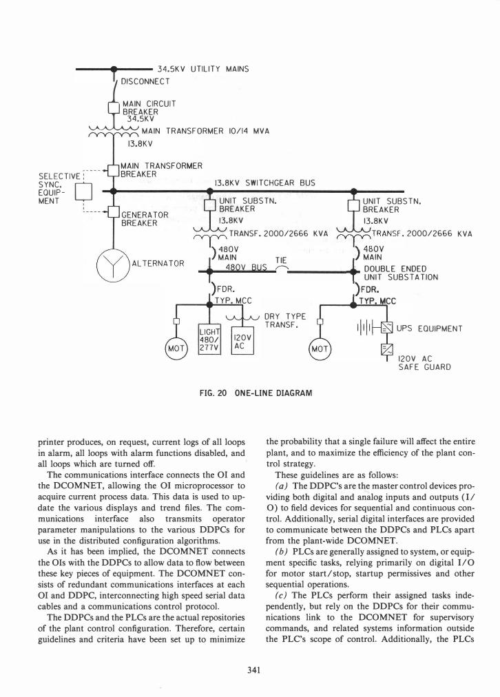
In normal operation, the turbo-generator plant is paralleled with the 34.5 kV main of the electric utility through the main transformer. Due to variations in the heat value of the refuse, the steam production of the boilers will fluctuate, as will the power output on the generator side. The generator delivers power to the electric utility and simultaneously provides the power for the facility.
As provided for in the power supply arrangement, the generator is connected via the generator breaker to the 1 3 .8 kV bus bars. The 13 . 8 kV switch gear is executed as a single collecting bus bar installation with draw-out circuit breakers. The medium voltage switchgear consists of four breaker panels and drawer sections for protective relaying and metering. Switching arrangements are designed to enable the turbo-generator to operate isolated from the grid in case of failure in the 34.5 kV line. Selective automatic synchronizing equipment, which permits paralleling to the utility upon start-up, is provided for this purpose.
In case of failure of the utility, the generator is free running in the isochronous mode, supplying only auxiliary power for continuous plant operation and refuse burning. Upon restoration of the utility availability, the generator is resynchronized for immediate load ramping.
The low voltage switchgear is supplied from the 1 3 . 8 kV bus via two 13 .8/0.48 kV transformers, each of 2000/2666 kVA capacity. The 480 V low voltage, double ended unit substation switchgear is contained in metal clad steel cabinets. Circuit breakers are of draw-out design. The entire double-ended unit substation is located directly on the turbine operating floor in visual range of the control room operator. The dou- . hIe ended unit substation feeds five motor control centers for 480 V motor loads and the lighting system. Small 1 20 V AC power is taken from dry type distri-
340
bution transformers and associated panel boards, strategically located throughout the plant.
A simplified one-line diagram is shown in Fig. 20. All equipment and components that are implicitly
required for shut-down of the resource recovery facility in a controlled manner, such as all measuring and control installations, turbine control and its lubricant supply, fire alarm and emergency lighting system, etc., receive their power supply from the station battery in conjunction with an un interruptible 120 V AC safeguard supply.
Controls
The control system for the Warren County Resource Recovery Facility is a microprocessor-based, distributed digital control with CRT operator consoles. Within the system there are four distinct types of microprocessor-based equipment:
(a) CRT Operator Interface Console (01) (b) Distributed Digital Process Controller (DDPC) (c) Programmable Logic Controller (PLC) (d) Data Communications Network (DCOMNET)
The 01 provides the means for process monitoring, control parameter manipulation, alarm and data logging. An Operator interface consists of: one color CRT monitor with keyboard, a floppy disk drive unit, a DCOMNET interface, a graphic printer, and a microprocessor unit.
Displays on the 01 consist of interactive plant graphics, plant overview, group, detail, trend, system status, and plant alarm status displays. Each 01 is loaded with the same interactive graphics, groups, and alarms so that any 01 may control any plant system or device interfaced with the Digital Control System (DCS).
The keyboards allow an operator to move between various displays, acknowledge alarms, adjust control parameters, connect, disconnect, download, and checkpoint anyone of the DDPCs or PLCs attached to the data highways. Engineers may place the keyboards in a configuration mode to allow for control tuning or configuration changes to the system programming.
The floppy disk drives are used to permanently store the operating system 01 and DDPC configuration programs which are downloaded prior to any plant cold restart. The hard disk drives are also used to record trend data for archival purposes. Permanent archiving is achieved by transferring trend information to a floppy disk for storage.
The graphic printer capability will allow an operator to make a hard copy of present displays on the 01 CRT monitor. The printer also provides an automatic means of logging both process and system status alarms, in the order in which they are detected. The
T 34.SK V UTILITY MAINS
MAIN CIRCUIT BREAKER
34.SKV
jilSCONNECT
-"'/"""'"'-"'/"""'"' MAIN TRANSFORMER 10/14 MVA
SELECTIVE: SYNC. 0 EOUIP-
13.8KV SWITCHGEAR BUS
MENT UNIT SUBSTN. UNIT SUBS TN. BREAKER BREAKER 13.8KV 13.8KV � TRANSF.2000/2666 KVA
�TRANSF. 2000/2666
) 480V ) 480V KVA
t. MAIN TIE t. MAIN _ 480V BUS � ______ ...... DOUBLE ENDED
UNIT SUBS T A TION )FDR. )FDR. TYP. MCC TVP.MCC
UGH 4801 277V
120V AC
DRY TYPE TRANSF. EQUIPMENT
120V AC SAFE GUARD
FIG. 20 ONE-LINE DIAGRAM
printer produces, on request, current logs of all loops in alarm, all loops with alarm functions disabled, and all loops which are turned off.
The communications interface connects the 01 and the DCOMNET, allowing the 01 microprocessor to acquire current process data. This data is used to update the various displays and trend files. The communications interface also transmits operator parameter manipulations to the various DDPCs for use in the distributed configuration algorithms.
As it has been implied, the DCOMNET connects the Ols with the DDPCs to allow data to flow between these key pieces of equipment. The DCOMNET consists of redundant communications interfaces at each 01 and DDPC, interconnecting high speed serial data cables and a communications control protocol.
The DDPCs and the PLCs are the actual repositories of the plant control configuration. Therefore, certain guidelines and criteria have been set up to minimize
341
the probability that a single failure will affect the entire plant, and to maximize the efficiency of the plant control strategy.
These guidelines are as follows: (a) The DDPC's are the master control devices pro
viding both digital and analog inputs and outputs (II 0) to field devices for sequential and continuous control. Additionally, serial digital interfaces are provided to communicate between the DDPCs and PLCs apart from the plant-wide DCOMNET.
(b) PLCs are generally assigned to system, or equipment specific tasks, relying primarily on digital 110 for motor start/stop, startup permissives and other sequential operations.
(c) The PLCs perform their assigned tasks independently, but rely on the DDPCs for their communications link to the DCOMNET for supervisory commands, and related systems information outside the PLC's scope of control. Additionally, the PLCs

supply status information to the DDPCs for use in the control of other systems and to relay information to the 01.
(d) The physical control entity of the plant is partitioned such that a component failure within a duplicate subsystem in the plant will not require the remaining subsystems to cease operations.
(e) Those subsystems where duplication does not exist are provided with redundance in the control system.
PLANT MODIFICATIONS
The following modifications have been incorporated into the plant design. The reason for each change and the status of its implementation are described below.
Demineralized Water Storage
The demineralized water storage capacity was increased from 3000 gal to 24,000 gal, and a 100 gpm pump was added to supplement the two original 20 gpm pumps. This change has been completed, and the system is in service. The reason for the change was to provide increased demineralized water storage, makeup, and surge capacity found to be needed during transients and for boiler fill.
Auxiliary Cooling Water System
In the original plant design, the condensers and all auxiliary equipment utilized the same cooling water systems with the cooling tower providing the heat sink for the system. After the plant experienced problems with plugging and scaling of heat exchangers, a number of auxiliaries were removed from the plant cooling water system, and a separate auxiliary cooling water system was designed to provide additional water chemistry control. The separate closed-loop system was provided by adding two 100% capacity plate type heat exchangers which transferred the auxiliary heat load to the plant cooling water system. A water softener was added to provide the chemistry control.
In addition, a head tank was added in the auxiliary cooling system to assure a source of cooling water to the turbine-driven boiler feed pump and diesel-driven air compressor in the event of total loss of plant electrical power. Necessary pumps, piping, valves, and instrumentation were also added to complete the system design.
The system has been operating for several months with no evidence of plugging or scaling. The following
342
auxiliaries are served by the auxiliary cooling water system:
(a) boiler feed pump bearing coolers (b) boiler feed pump turbine bearings (c) air compressors (3) (d) I .D. fan bearing coolers (e) I .D. fan variable speed drive coolers (/) sample coolers
Boiler Feed Pump Change
This change involved replacing the three single-stage boiler feed pumps with multi-stage type pumps. The two electric motors and the steam turbine were not changed. The flow was increased from 1 50 gpm to 170 gpm. The original single-stage pumps proved unreliable for the application. The pump manufacturer recommended changing to multi-stage type pumps. The new pumps have been in operation for several months and have given good service.
Magnetic Separator Addition
A magnetic separator was added over the existing inclined belt ash conveyor. Also, a 12 X 16 ft building was added for ferrous metal container storage. This change was required to remove ferrous metal left in the ash stream after the grizzly separator to minimize jamming of equipment such as the ash sampler and the mixing drum. The magnetic separator has performed well and has substantially reduced jamming of the ash handling equipment.
Ash/Water Separator Addition
The residue storage, ash mixing, and transfer buildings each originally employed sump pockets with centrifugal type sump pumps to transfer drainage, including wash down water directly to the boiler quench water tank. This drainage was frequently high in solids content and clogged the drain lines from the sump pocket.
A new design was developed for the drain system which added a 1000 gal ash/water separator and replaced the centrifugal type sump pumps with motor operated diaphragm pumps. The sump pumps discharge into the 1000 gal separator. The ash/water separator is a concrete settling basin with a weir. Clear water from the separator can be reused for washdown water in any of the three residue handling buildings. The ash accumulated in the ash/water separator must be periodically removed. The separator is open to allow access for manual cleaning.
The new ash/water separator pumps and associated valves and piping have been in service for several months with no significant problems reported.
SUMMARY
The Warren County Energy Resource Facility and its processing equipment has been described in detail. Construction of the facility was completed in June, 1988, and acceptance testing was successfully completed in April, 1 989. A severe shortage in MSW deliveries delayed full capacity shakedown and equipment checkout, which contributed to the late completion of the Acceptance Tests.
343
Throughput averaged 537 TPD of essentially reference fuel during the three-day acceptance test, or 1 34% of guaranteed capacity. The residue combustibles content remained below the 5% guarantee despite the high throughput. Electrical generation was significantly above guarantee during the test period.
The MSW delivery shortage has been resolved by the County and initial equipment shakedown difficulties have been overcome such that the plant now normally operates at full capacity. Through January 3 1 , 1 990, the plant had processed approximately 1 39,092 tons of MSW.
Key Words: Combustion; Facility; Mass Burn; New Jersey; Power Generation; Refuse; Warren County
Top Related