


Languages
Pages
Legal


K. Amine (PI)
Z. Chen, H. Wu, Y. Li, Z. Chen, J. Lu, and R. Xu,
Argonne National LaboratoryDOE merit review
June 6th ~10th , 2016
This presentation does not contain any proprietary, confidential, or otherwise restricted information.
New High-Energy Electrochemical Couple for Automotive Applications
Project ID: ES208
Overview
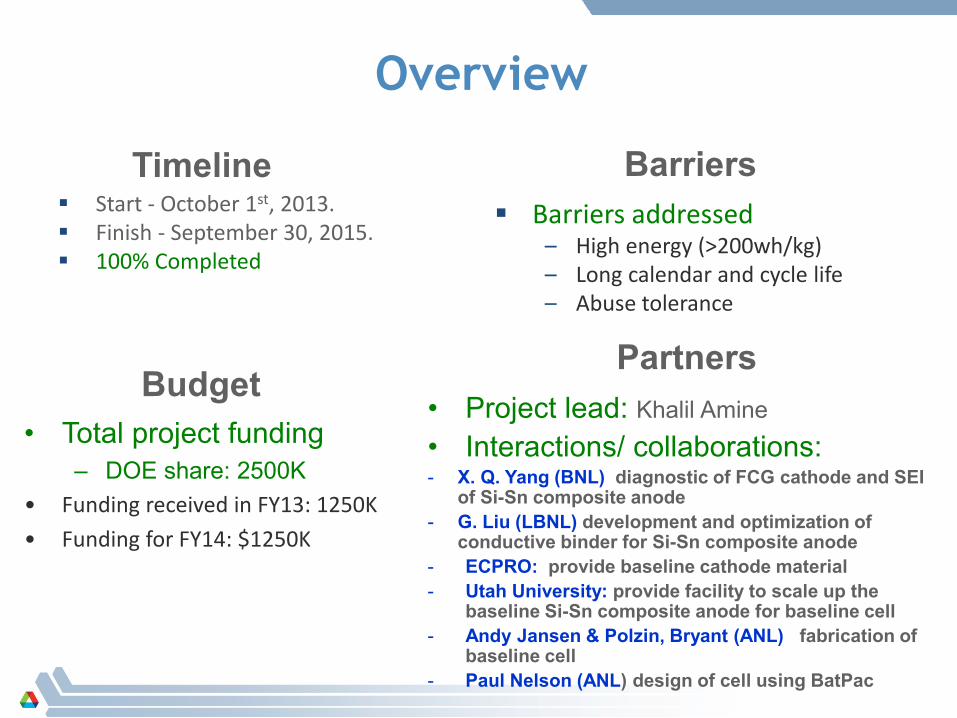
Start - October 1st, 2013. Finish - September 30, 2015. 100% Completed
Barriers addressed– High energy (>200wh/kg)– Long calendar and cycle life– Abuse tolerance
• Total project funding– DOE share: 2500K
• Funding received in FY13: 1250K• Funding for FY14: $1250K
Timeline
Budget
Barriers
• Project lead: Khalil Amine• Interactions/ collaborations:- X. Q. Yang (BNL) diagnostic of FCG cathode and SEI
of Si-Sn composite anode - G. Liu (LBNL) development and optimization of
conductive binder for Si-Sn composite anode - ECPRO: provide baseline cathode material- Utah University: provide facility to scale up the
baseline Si-Sn composite anode for baseline cell- Andy Jansen & Polzin, Bryant (ANL) fabrication of
baseline cell- Paul Nelson (ANL) design of cell using BatPac
Partners

Relevance and project Objectives Objective: develop very high energy redox couple (250wh/kg)
based on high capacity full gradient concentration cathode (FCG) (230mAh/g) and Si-Sn composite anode (900mAh/g) with long cycle life and excellent abuse tolerance to enable 40 miles PHEV and EVs
This technology, If successful, will have a significant impact on: – Reducing battery cost and expending vehicle electrification– Reduce greenhouse gases– Reduce our reliance on foreign oil

Milestones• March 2015:
– Improve efficiency of SiO-SnCoC anode to over 80% (completed)
• August 2015:– Finalize the Optimization of the processing of SiO-SnCoC-MAG to
get uniform electrodes and demonstrate up to 100 cycles of SiO-SnCoC-MAG using new LiPAA binder (completed)
• September 2015: – Optimize and scale up of Improve further FCG cathode with
210mA/g at 4.5V (completed).– Provide FCG cathode (1Kg) to CAM facility for cell design and build
( completed)– Supply 14 cells to INL for testing and validation (completed)
4
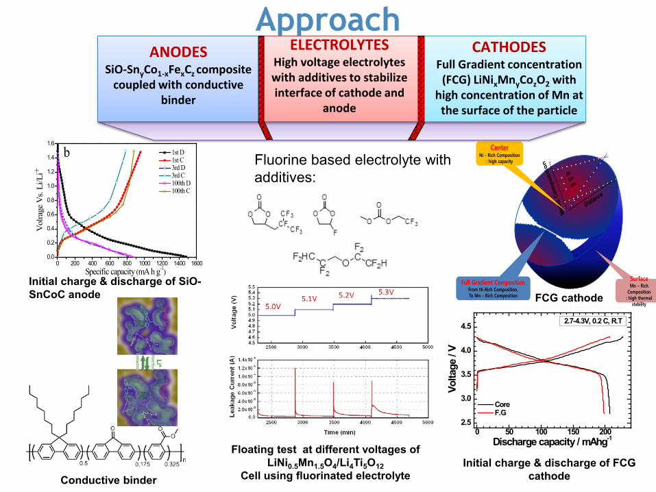
CenterNi - Rich Composition
: high capacity
Full Gradient CompositionFrom Ni-Rich Composition, To Mn – Rich Composition
SurfaceMn – Rich
Composition: high thermal
stability
0 200 400 600 800 1000 1200 1400 16000.0
0.2
0.4
0.6
0.8
1.0
1.2
1.4
1.6
Vol
rage
Vs.
Li/L
i+
b 1st D 1st C 3rd D 3rd C 100th D 100th C
Specific capacity (mA h g-1)
Approach
0 50 100 150 2002.5
3.0
3.5
4.0
4.5
Core F.G
2.7-4.3V, 0.2 C, R.T
Volta
ge /
VDischarge capacity / mAhg-1
ANODESSiO-SnyCo1-xFexCz composite
coupled with conductive binder
ELECTROLYTESHigh voltage electrolytes with additives to stabilize interface of cathode and
anode
CATHODESFull Gradient concentration
(FCG) LiNixMnyCozO2 with high concentration of Mn at
the surface of the particle
Fluorine based electrolyte with additives:
Floating test at different voltages of LiNi0.5Mn1.5O4/Li4Ti5O12
Cell using fluorinated electrolyteInitial charge & discharge of FCG
cathodeConductive binder
Initial charge & discharge of SiO-SnCoC anode FCG cathode

Technical accomplishments
Optimized the process of making FCG cathode and demonstrate capacity as high as 210mAh/g with 2.7 tap density
Characterized the FCG material using soft and hard X-ray in collaboration with BNL
Scaled up FCG cathode to 1Kg level for electrode making using CAMP facility at Argonne
Build cells based on FCG cathode and graphite anode and demonstrate good cyclability at high voltage
Developed a new prelithiation process to eliminate the large initial irreversible loss of SiO-SnCoC anode
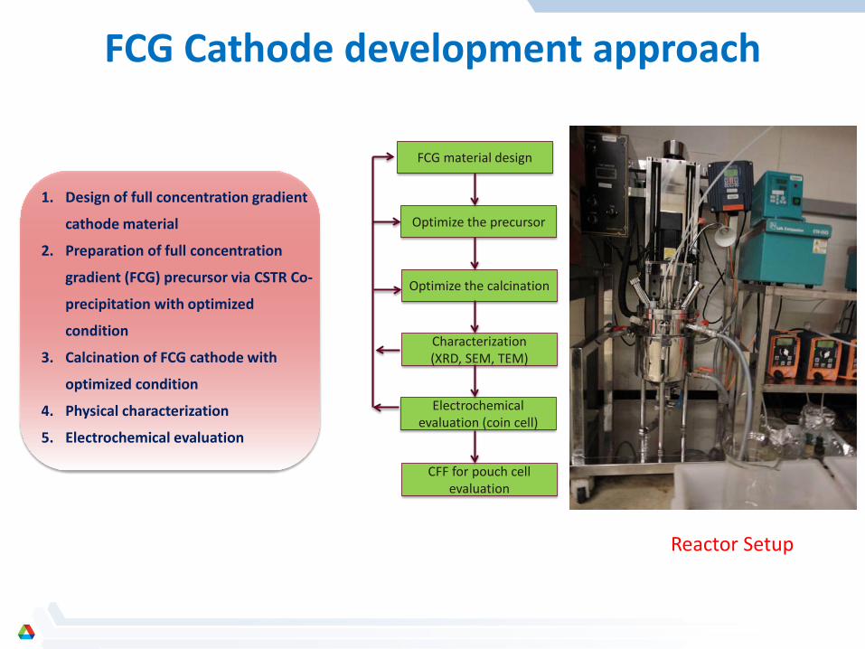
FCG Cathode development approach
1. Design of full concentration gradient
cathode material
2. Preparation of full concentration
gradient (FCG) precursor via CSTR Co-
precipitation with optimized
condition
3. Calcination of FCG cathode with
optimized condition
4. Physical characterization
5. Electrochemical evaluation
FCG material design
CFF for pouch cell evaluation
Electrochemicalevaluation (coin cell)
Optimize the precursor
Optimize the calcination
Characterization(XRD, SEM, TEM)
Reactor Setup

Characteristics of FCG gradient precursor & final active material made from hydroxide process after optimization
High tap density: 2.7 g/ccparticle distribution: D50=11.64 um
The average composition: ~LiNi0.6Co0.2Mn0.2O2Outer: ~LiNi0.46Co0.23Mn0.41O2Inner: ~LiNi0.8Co0.1Mn0.1O2
FCG (6:2:2) : LiNi0.6Co0.2Mn0.2O2
Ni0.6Co0.2Mn0.2(OH)2
0
10
20
30
40
50
60
70
80
00.
120.
240.
360.
48 0.6
0.72
0.84
0.96
1.08
1.21
1.33
1.45
1.57
1.69
1.81
1.93
2.05
2.17
2.29
2.41
2.53
2.65
2.77
2.89
3.01
3.13
3.25
3.38 3.
53.
623.
743.
863.
98 4.1
4.22
Mn K
Co K
Ni KRela
tive
inte
nsity
Distance (µm)center edge
Ni
Mn
Co

• 2.7 – 4.3 V (192 mAh/g)• 2.7 – 4.4 V (198 mAh/g)• 2.7 – 4.5 V (210 mAh/g)
Electrochemical performance of FCG cathode at different cut-off voltages

2\B&++&%.''B/B+4%#'C.)-4+4./').'HH$J'
!"A)M''J0,I)UNMNMK''
Electrochemical performance of FCG cathode at 55oC
JX[WVOX[K' JX[WVOX[K'

TR-XRD/MS of FCG (6:2:2) and NMC (6:2:2) baseline
A! @:)"G'1?'#)C'"&+&)C&'O).'40"'<H='$JS'K8"4%#'G:)C&'.")%C4*$%'T"$3'+)/&"&K'.$'K4C$"K&"&K'CG4%&+'G:)C&'
LiNi0.6Mn0.2Co0.2O4 (Baseline NMC 622) LiNi0.6Mn0.2Co0.2O4 (FCG-6:2:2))
AJ$%B&%.")*$%'#")K4&%.'OFJ]S'C)3G+&' C:$6C'38B:'-&l&"'.:&"3)+'C.)-4+4./' .:)%'-)C&+4%&'(hJ'9??''W'<C.'G:)C&'.")%C4*$%'$BB8""&K').'B)E'<^=' mJ'

845 850 855 860 865 870 875 880
Nor
mal
ized
inte
nsity
(arb
.uni
t)
Energy (eV)845 850 855 860 865 870 875 880
Nor
mal
ized
inte
nsity
(arb
.uni
t)
Energy (eV)
Ni L-edge soft XAS for baseline NMC622 (left ) and FCG-622 (right) Using Fluorescence detection (FY, bulk probing)
25 oC
150 oC
200 oC
250 oC
300 oC
350 oC
400 oC
450 oC
500 oC
25 oC
150 oC
200 oC
250 oC
300 oC
350 oC
400 oC
450 oC
500 oC
Ni reduction reflected as the lower energy peak occurred quickly at low temperature (~150 oC) in baseline NMC622. In contrast, FCG-622 is more stable and Ni is stable up to 250 oC and gradually reduced, and completed at 350 oC
Baseline-NMC622FCG-622

845 850 855 860 865 870 875 880
Nor
mal
ized
inte
nsity
(arb
.uni
t)
Energy (eV)845 850 855 860 865 870 875 880
Nor
mal
ized
inte
nsity
(arb
.uni
t)
Energy (eV)
25 oC
150 oC
200 oC
250 oC
300 oC
350 oC
400 oC
450 oC
500 oC
25 oC
150 oC
200 oC
250 oC
300 oC
350 oC
400 oC
450 oC
500 oC
- The structural change at near surface also shows same trend with bulk structure.- Ni reduction temperature is well coincident with the temperature of the phase
transition and O2 release in TR-XRD/MS data
Ni L-edge soft XAS for Baseline NMC622 (left ) and FCG (right)Using partial electron yield detection (PEY, Surface probing)
Baseline NMC622FCG NMC622

0 10 200
100
200
Cap
acity
Cycle number
Disch,mAh/g Ch,mAh/g
(a)
YC722PFM60% SiO-SnCoC+30%PFM +10%SP+C6H5Cl
Low efficiency: 65%~70%.
Optimization of SiO-SnCoC composite anode
0 300 600 900 1200 15000
1
2
3(b)
Vol
tage
(V)
Capacity (mAh/g)
1 cycle 2 cycle 3 cycle
Half cell SiO-SnCoC : 90/5%Timecal/5%PI
Electrode loading: 2.5mg/cm2
1st cycle reversibility between 70 to 72%.
Main Issues:Conductive binder (PFM) shows poor
performance with Si-SnCoC composite
14
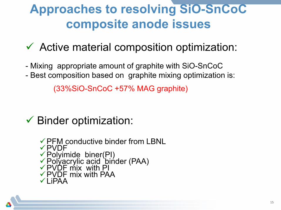
Active material composition optimization:- Mixing appropriate amount of graphite with SiO-SnCoC- Best composition based on graphite mixing optimization is:
(33%SiO-SnCoC +57% MAG graphite)
Binder optimization:
PFM conductive binder from LBNLPVDFPolyimide biner(PI)Polyacrylic acid binder (PAA)PVDF mix with PIPVDF mix with PAALiPAA
Approaches to resolving SiO-SnCoCcomposite anode issues
15

0 20 400
200
400
600
800
1000
Cap
acity
(mA
h/g)
Cycle number
Ch Disch
33% SiO-SnCoC+57%GC+5%LiPAA+5%C-45
1st cycle C.E. 81 %.
00.20.40.60.8
11.21.41.6
0 200 400 600 800
Volta
ge, (
V)
Capacity (mAh/g)
1. The cell shows high 1st C.E. efficiency (81%).2. The cell shows good rate performance.3. The cell shows high capacity (670 mAh/g) and
excellent cycle life so far.
33%SiO-Sn30Co30C40/57%MAG graphite with 5%LiPAA shows the best performance with 81% 1st cycle efficiency
33%SiO-Sn30Co30C40/57%MAG graphite /5%LiPAA/ 5%C-45 formulation was used by CAMP facility to fabricate electrode for cell
build

0
50
100
150
200
250
0 5 10 15 20 25 30
Cap
acit
y, m
Ah
/g
Cycle Number
CYCLE PERFORMANCE
0.0
0.5
1.0
1.5
2.0
2.5
3.0
3.5
4.0
4.5
0 50 100 150 200 250
Vo
ltag
e, V
Capacity, mAh/g
VOLTAGE PROFILE
Initial performance of Full cell SiO-SnCoC-MAG/FCG cathode
• The first discharge capacity is only 170mAh/g due to large initial irreversible loss of SiO-SnCoC-Mag anode
• Need to incorporate a pre-lithiation to maximize cathode capacity
17

1st C cap (mAh/g) 2181st D Cap (mAh/g) 1891st Cycle Eff (%) 86.5
Coupling FCG with Graphite instead of SiO-SnCoC-MAG shows excellent cycle life
00.5
11.5
22.5
33.5
44.5
0 100 200 300
Volta
ge, (
V)
Capacity (mAh/g) 020406080
100120140160180200
0 10 20 30
Capa
city
, (m
Ah/g
)Cycle Number
Discharge Capacity vs Cycle Life
By replacing SiO-SnCoC-MAG composite with graphite, the cycle life of the full cell with FCG cathode improved significantly,
Based on the result above, we decided to build FCG/MAG full cell while developing a pre-lithiation process to enable Si-SnCoC anode

Electrode Architecture and Cell Assembly based on FCG and MAG Graphite
Pouch cell build is using – Anode (LN3012-178) -> MagE graphite– Cathode (LN3012-179) -> FCG
Average Entire Cell Weight, as delivered: 11.0405 g
Electrode Architecture– Cathode Electrode Dimensions : 31.3 mm W x 45.0 mm T
• Cathode Electrode Area : 14.1 cm2 per side
– Anode Electrode Dimension : 32.4 mm W x 46.0 mm T• Anode Electrode Area : 14.9 cm2 per side
Cell Assembly– Total Number of Layers : 13
• Cathode Layers : 5 Double Side Layers + 2 Single Side Layers (outer 2 electrodes)• Anode Layers : 6 Double Side Layers
– Separator Used : Celgard 2325 - Trilayer PP/PE/PP– Electrolyte Used : 1.2M LiPF6 in EC:EMC (3:7 wt%)– Applied Cell Pressure during testing: ~15 kPa
Vehicle Technologies Program19

Cathode & Anode Formulation
Vehicle Technologies Program20
Cathode Formulation (Dry Composition)– 90 wt% FCG, Khal ABR 2014 (Lot 011915/012015)
– 5 wt% Timcal C-45 Carbon Black– 5 wt% Solvay 5130 PVDF Binder
Cathode Electrode Properties– Aluminum Foil Thickness: 20 microns– TTL DS Electrode Thickness: 159 microns– TTL SS Coating Thickness: 69 microns– Cathode Coating: 17.20 mg/cm² (SS)
(Total Material wt; No Foil)– Capacity: 2.87 to 3.06 mAh/cm²– Target Porosity: 39.5 %– Coating Density: 2.47 g/cm3
n:p Ratio: 1.10 to 1.16
Anode Formulation (Dry Composition)– 91.83 wt% Hitachi MagE– 2 wt% Timcal C-45 Carbon Black– 6 wt.% Kureha 9300 PVDF– 0.17wt.% Oxalic Acid
Anode Electrode Properties– Copper Foil Thickness: 10 microns– TTL DS Electrode Thickness: 162 microns– TTL SS Coating Thickness: 76 microns– Anode Coating: 11.33 mg/cm² (SS)
(Total Material wt; No Foil)– Capacity: 3.44 to 3.50 mAh/cm²– Target Porosity: 31.2 %– Coating Density: 1.49 g/cm3

0255075100125150175200225
050
100150200250300350400450500
0 100 200 300 Capa
city
, (m
Ah/g
of c
atho
de o
xide
)
Capa
city
, (m
Ah)
Cycle #
Average Discharge Capacity
Average Discharge Capacity (mAh)Average Discharge Capacity (mAh/g)
Initial performance of full cell based FCG (6:2:2) /MAG
0
20
40
60
80
100
120
140
160
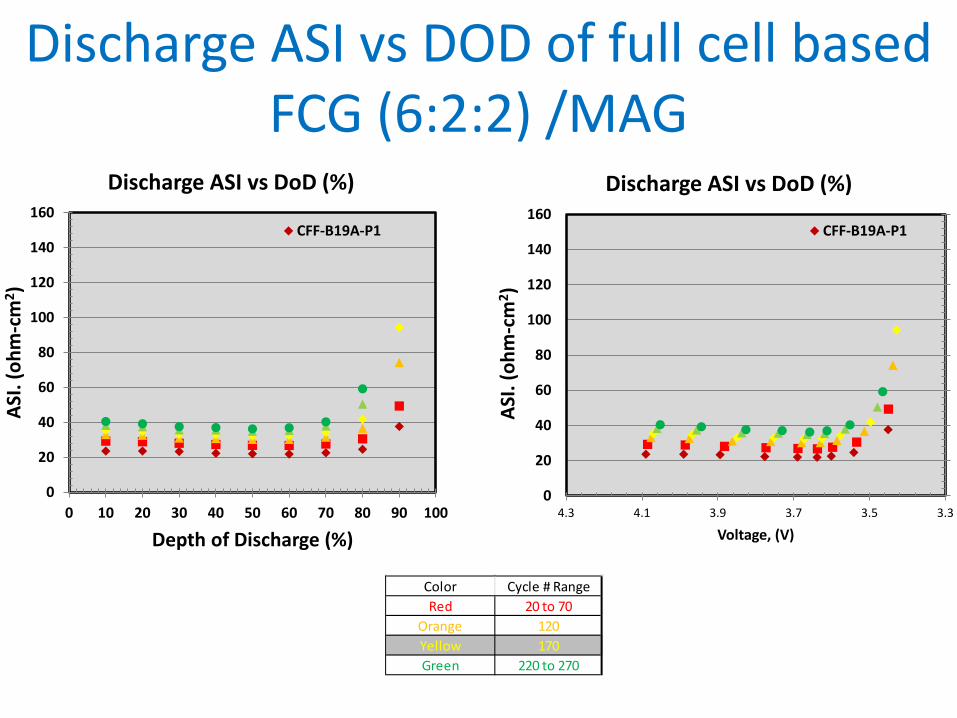
0 10 20 30 40 50 60 70 80 90 100
ASI.
(ohm
-cm
2 )
Depth of Discharge (%)
Discharge ASI vs DoD (%)
CFF-B19A-P1
0
20
40
60
80
100
120
140
160
3.33.53.73.94.14.3AS
I. (o
hm-c
m2 )
Voltage, (V)
Discharge ASI vs DoD (%)
CFF-B19A-P1
Color Cycle # RangeRed 20 to 70
Orange 120Yellow 170Green 220 to 270
Discharge ASI vs DOD of full cell based FCG (6:2:2) /MAG
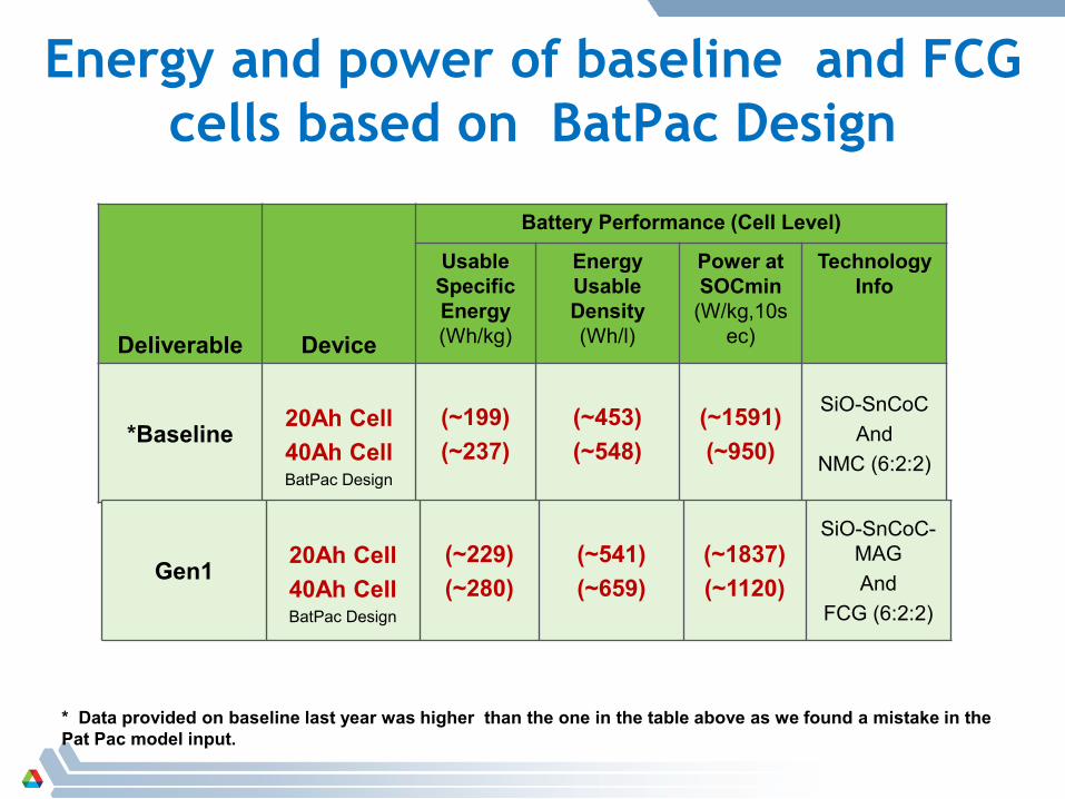
Deliverable Device
Battery Performance (Cell Level)
Usable Specific Energy(Wh/kg)
Energy Usable Density (Wh/l)
Power at SOCmin
(W/kg,10sec)
TechnologyInfo
*Baseline 20Ah Cell40Ah CellBatPac Design
(~199)(~237)
(~453)(~548)
(~1591)(~950)
SiO-SnCoCAnd
NMC (6:2:2)
Energy and power of baseline and FCG cells based on BatPac Design
Gen1 20Ah Cell40Ah CellBatPac Design
(~229)(~280)
(~541)(~659)
(~1837)(~1120)
SiO-SnCoC-MAGAnd
FCG (6:2:2)
* Data provided on baseline last year was higher than the one in the table above as we found a mistake in the Pat Pac model input.

ANL discover a new approach to pre-lithiation by activating Li2O at the cathode side at high voltage
Li2O : Li sources to compensate for lithium consumption in lithium-ion batteries (improve fist cycle irreversibility of silicon and other anodes) (capacity of Li2O ~ 1650 mAh/g)
Li2O could be combined with all cathodes non-containing Li such as: S; MnO2, V2O5, FeF3, SeSx……
Pre-lithiation of SiO-SnCoC to reduce the negative impact of large initial irreversible lose

LIB in the market is anode limitedbattery
- To balance battery with Graphite (CE:90%):1 g of graphite delivers 3.2 mAh and needs 2 (+10%)= 2.2g of cathode material with (160 mAh/g) to have a cell with 3.2 mAh. (0.2 g of the cathode is a dead weight in the battery).
- To balance battery with Graphite/Silicon (CE:80%, capacity 728 mAh/g):
1 g of graphite/silicon delivers 6.4 mAh and needs 4 (+20%)= 4.8g of cathode material with (160 mAh/g) to have a cell with 6.4 mAh. (0.8 g of the cathode is a dead weight in the battery).

0 100 200 300 400 500 6002.0
2.5
3.0
3.5
4.0
4.5
5.0
621
Gen II electrolyte Gen I electrolyte
Pot
entia
l (V
) vs.
Li
Capacity in mAh per gram of HEM
585
Voltage profile versus capacity of HEM-Li2O/Li half-cell with Gen I and Gen II electrolytes (I = 10 mA/g).
HEM: Li1.2Ni0.15Mn0.55Co0.1O2
High charge capacity is obtained when adding 15%Li2O. Two times the charge capacity of the HEM material.
Li2O with HEM electrode
Gen I: LiPF6/EC:EMC (3:7)GenII: LiClO4/EC:EMC (3:7)

0 200 400 600 800 1000
1.5
2.0
2.5
3.0
3.5
LTO "HEM" in Gen I
HEM in Gen I
LTO "HEM-Li2O" in Gen IVo
ltage
(V)
Capacity in mAh per gram of HEM
HEM-Li2O in Gen I
Voltage profile versus charge capacities of HEM/ LTO and HEM-Li2O/LTO full cells (I = 3 mA/g) and recovered LTO/Li half-cell in Gen I electrolyte (I = 8 mA/g).
Proof of activation : amount of Li in the full cell using LTO anode
The amount of lithium inserted in the LTO (from HEM-Li2O) in mAh/g equivalent is 600 mAh/g.
The amount of lithium inserted in the LTO (from HEM) in mAh/g equivalent is only 275 mAh/g.

F4"C.AB/B+&'5$+.)#&'G"$c+&'5&"C8C'B)G)B4./')%K'B/B+4%#'G&"T$"3)%B&'O4%C&.S'$T'N2hM,4?1Q@41A@%J$J')%K'N2hQ@41A@%J$J'T8++'B&++CE''
#!a:&'T8++'B&++'B)G)B4./'6)C'43G"$5&K'T"$3'<e9'3!:Q#'.$'?HY'3!:Q#E'
#!($'&w&B.'$%'.:&'B/B+4%#'$T'T8++'B&++C'$"':)+T'B&++CE'
#!a:&':4#:&"'c"C.'B:)"#&'C:$6C'%$'%&&K'$T'8C4%#')'+$.'$T',4?=E'''
?%K''G"$$T'$T'B$%B&G.'64.:'T8++'B&++'@41A@%J$1'3).&"4)+'64.:'+$6'J2';99Ae=I''

Responses to Previous Year Reviewers’ Comments
• Question: reviewer 2 The anode material target of 900 mAh/g, the reviewer said, can be sufficient for the DOE PHEV-40 target. It would be of additional benefit, the reviewer concluded, to investigate the potential of the material to exceed 1,000 mAh/g and thus also to address EV application !
• Answer: the reviewer is absolutely righ. However, the targeted energy density in this project is 200wh/kg and we believe less than 900mAh/g anode capacity can easily meet this target
• Question : reviewer No:4 The key barriers that must be addressed, the reviewer stated, is long calendar and cycle life, but it is not clear how to address this challenge. In particular, the reviewer said, a solution for the instability of the SEI layer and attack by dissolved Mn from the surface of the FCG cathode to the anode side were not clearly discussed or planned. Also, the current anode system shows poor capacity and cycle life, problems the reviewer said could not be solved by addressing only the binder
• Answer: the issue of Mn dissolution and its imp[act on the SEI of the anode was resolved by adding LiBDOF electrolyte additive that resist any attack by Mn dissolution. In the past we have demonstrated 1000 cycle with 91% retention using FCG/MCMB.
• The Si anode we developed can provide very high capacity, however, we blend it with large amount of carbon to get 600mAh/g that we believe can meet the 200wh/kg energy requirement. The cycle life vs lithium is excellent , however, the cycle life in full cell was not satisfactory because of the difficulty of CAM lab to make good electrodes during scale up!
29

Responses to previous year reviewers' comments
• Question: reviewer 1: the Nickel contact on FCG should increase to get high capacity.
• Answer: we totally agree with the reviewer. The development of Ni rich gradient will require more time to optimize the gradient slop. This will be the subject of a different project that we hope will be supported by DOE.
30

Collaborations• X.Q. Yang of BNL
• Diagnostic of FCG and SEI of Si-Sn composite electrodes using soft & hard X-ray.
• G. Liu (LBNL) •Development and optimization of conductive binder for Si-Sn composite anode
•H. Wu (ANL) •Optimize the synthesis of FCG cathode
•A. Abouimrane (ANL) •Development of SiO-SnyCo1-xFexCz anode
•J.Lu & Z. Chen (ANL)•Characterization of cathode, anode and cell during cycling using In-situ techniques
• ECPRO : Baseline cathode material
•University of Utah : Facility to scale up the baseline Si-Sn composite anode for baseline cell
• A. Jansen & B. Polzin (ANL)•Design & fabrication of baseline cell

Summary Relevance
• enable low battery cost by increasing energy density • Low battery cost will lead to mass electrification of vehicle and reduction of both
greenhouse gases and our reliance on foreign oil Approaches
• develop very high energy redox couple (250wh/kg) based on high capacity full gradient concentration cathode (FCG) (210mAh/g) and Si-Sn composite anode (670mAh/g) with long cycle life and excellent abuse tolerance to enable 40 miles PHEV and EVs
Technical Accomplishments• Optimize the process of making FCG cathode and demonstrate capacity as high as
210mAh/g with 2.7 tap density• Scale up FCG cathode to 1Kg level for electrode making using CAMP facility at Argonne• Improve the efficiency of SiO-Sn30 Co30C40 anode to 81% by Developing SiO-Sn30
Co30C40 –MAG graphite composite formulation and scale up the new composite to 1Kg level.
• Develop a novel pre-lithiation process to overcome the first irreversible loss at the Si0SnCoC anode
Proposed Future work• The project ended at the end of September 2015
32
Top Related