


Languages
Pages
Legal


USER MANUAL
NetGuardian 480/432 G3 & G4
April 22, 2019
Visit our website at www.dpstelecom.com for the latest PDF manual and FAQs.
Firmware Version 2.0N
D-PK-NG480D-PK-NG432
D-UM-NG480/NG432

© 2019 DPS Telecom
This document contains proprietary information which is protected by copyright. All rights are reserved. No part of thisdocument may be photocopied without prior written consent of DPS Telecom.
All software and manuals are copyrighted by DPS Telecom. Said software and manuals may not be reproduced, copied,transmitted or used to make a derivative work, by either mechanical, electronic or any other means in whole or in part, withoutprior written consent from DPS Telecom, except as required by United States copyright laws.
The material in this manual is for information purposes and is subject to change without notice. DPS Telecom shall not beliable for errors contained herein or consequential damages in connection with the furnishing, performance, or use of thismanual.
Notice
Revision History
April 22, 2019
July 18, 2018
October 28, 2016
October 16, 2014
March 4, 2014
Support for Modbus added
Merged with G3 manual, updated firmware
Added Derived Controls and Derived Expansion Controlssections.
Added Expansion Alarms and Controls section
Initial Release

ContentsVisit our website at www.dpstelecom.com for the latest PDF manual and FAQs
NetGuardian 480/432 Overview1 1
Specifications2 2
Shipping List3 3
Optional Shipping Items - Available by Request3.1 4
Installation4 5
Tools Needed4.1 5
Mounting4.2 5
NetGuardian Front Panel5 6
NetGuardian Back Panel6 7
Power Connection6.1 8
LAN Connection6.2 9
Serial Connection6.3 9
Alarm and Control Relay Connectors6.4 10
NetGuardian 432 G3 Pinouts6.4.1 10
NetGuardian 432 G4 Pinouts6.4.2 11
NetGuardian 480 G3 Pinouts6.4.3 12
NetGuardian 480 G4 Pinouts6.4.4 13
Discrete Alarms6.5 13
Optional 66 Block Connector6.6 14
D-Wire Sensor Input (analogs)6.7 15
Analog Step Sizes6.7.1 15
Quick Start: How to Connect to the NetGuardian7 16
...via Craft Port (using TTY Interface)7.1 16
...via LAN7.2 22
TTY Interface8 23
Configure Serial Port via TTY8.1 24
Quick Turn Up9 25
How to Send Email Notifications9.1 25
How to Send SNMP Traps9.2 27
Provisioning Menu Field Descriptions10 29
System10.1 30
User Profiles10.2 31
Ethernet10.3 32
RADIUS10.4 33
Serial Port10.5 34
SNMP10.6 35

Notifications10.7 36
Notification Settings10.7.1 36
Schedule10.7.2 37
Alarms10.8 38
Controls10.9 39
Derived Controls10.9.1 40
Derived Expansion Controls10.9.2 41
Sensors10.10 42
Ping Targets10.11 45
Modbus Devices10.12 46
Modbus Registers10.13 48
System Alarms10.14 50
Timers10.15 50
Date and Time10.16 51
Monitoring via the Web Browser11 52
Alarms11.1 52
Controls11.2 53
Sensors11.3 54
Ping Targets11.4 55
System Alarms11.5 56
Graph11.6 57
Device Access Descriptions12 59
Firmware Upgrade13 60
Reference Section14 61
Front and Back Panel LEDs14.1 61
Display Mapping14.2 62
System Alarms14.3 64
SNMP Manager Functions14.4 66
SNMP Granular Trap Packets14.5 68
Frequently Asked Questions15 69
General FAQs15.1 69
Technical Support16 70
End User License Agreement17 72

1
NetGuardian 480/432 Overview1
As an easy-to-install, high-density RTU, the NetGuardian effectively monitors sites with a lot of discrete alarmpoints.
Effective, easy-to-install, light-capacity alarm monitoringThe NetGuardian (NG) is a compact, LAN-based, high-density remote telemetry unit. The NetGuardian is designedfor easy installation at remote sites with up to 80 discrete alarm points, making it cost-effective to deploy alarmmonitoring at your larger facilities.
Powerful monitoring for high-density sitesThe NetGuardian is based on the time-tested NetGuardian 832A design. This telco-grade remote is housed in adurable aluminum case. This SNMP remote is scaled to the needs of high-density sites that require a lot of discreteinputs.
· 32 (NetGuardian 432) or 80 (NetGuardian 480) Discrete Alarm Inputs· 4 Control Relay Outputs· 1 Reach-through serial port (terminal server)
Reach-through serial port gives LAN access to on-site equipmentThe NetGuardian also features a reach-through serial port. This port provides remote users with LAN-based Telnetaccess to a variety of on-site telecom equipment, including switches, radios, PBXs and many other devices.
SNMP or T/MonThe NetGuardian can report alarms to any SNMP manager or to the DPS Telecom T/Mon Remote Alarm MonitoringSystem. The NetGuardian can also report via SNMP and DCPx concurrently to the T/Mon.
Easy Alerts via Email or SNMPEmail notification reports alarm events to the e-mail addresses of specified personnel and creates a supplementalrecord of alarm events in addition to your master via SNMP traps.
Upgraded Web 2.0 InterfaceThe overhauled web interface that boasts several time-saving new tools, including new analog gauges. You'll alsonotice the impressive speed boost. Menus load very quickly, and the alarm status updates automatically withoutrequiring a page refresh.
Note: The NetGuardian 432 is a subset of the NetGuardian 480, so the content in this manual will beapplicable to both units. Any differences between the units will be clearly identified.

2
Specifications2
Discrete Alarm Inputs: 80 (NetGuardian 480) or 32 (NetGuardian 432)
Temperature Sensors: Support for up to 32 D-Wire Sensors (see below)
Sensor Thresholds: 4 per sensor
Digital Sensor Inputs: 1 (up to 16 total daisy-chained sensors)
Control Relays: 4 Form C
Maximum Voltage: 60 VDC / 120 VAC
Maximum Current: 1 Amp, AC / DC
Protocols: SNMPv1, SNMPv2c, SNMPv3, DCPx, TELNET, HTTP, HTTPS, SMTP, ICMP, RADIUS
Dimensions: 1.72" H x 17" W x 5.14" D
(4.4 cm x 43.18 cm x 13.1 cm)
Weight: 4 lbs. 3oz. (1.9 kg)
Mounting: 19" or 23" rack mount
Shipping Box Size: 22" x 6" x 16" and 8 lbs.
Power Input: -48VDC (-36 to -72 VDC)
(Optional) +24 VDC via 110VAC wall transformer (12 to 30 VDC)
(Optional) -24VDC (-18 to -36 VDC)
Current Draw: 250 mA @ -24VDC
125 mA @ -48VDC
Fuse: Resettable Fuse (Internal), if +24V Power Input
3/4 Amp GMT Fuse, if -48V or -24V Power Input
Interfaces: 1 RJ45 10/100BaseT full-duplex Ethernet port
1 Push button switch
Serial port options: RS232, RS485, 202, 33.6 K internal dialup modem
Switch for 202 tuning
USB connection for front panel craft port
Visual Interface: 6 Front Panel LEDs
6 Back Panel LED
Audible Notification: Alarm speaker with volume control (Optional)
Operating Temperature: 32°–140° F (0°–60° C)
Operating Humidity: 0%–95% non-condensing
MTBF: 60 years
Windows Compatibility: Windows 2000, XP, Vista, 7 32/64 bit
RoHS: 5/6

3
Shipping List3
Please make sure all of the following items are included with your NetGuardian. If parts are missing, or if you everneed to order new parts, please refer to the part numbers listed and call DPS Telecom at 1-800-622-3314.
NetGuardian D-PK-NG480, or D-PK-NG432
NetGuardian User Manual NetGuardian Resource CDD-UM-NG480/NG432
USB Cable 14 ft. Ethernet CableD-PR-046-10A-06 D-PR-923-10B-14
23" Rack Ears 19" Rack EarsD-CS-325-10A-01 D-CS-325-10A-00
x8 x43/8" Ear Screws Rack Screwsand Lock Washers 1-000-12500-062-000-60375-05
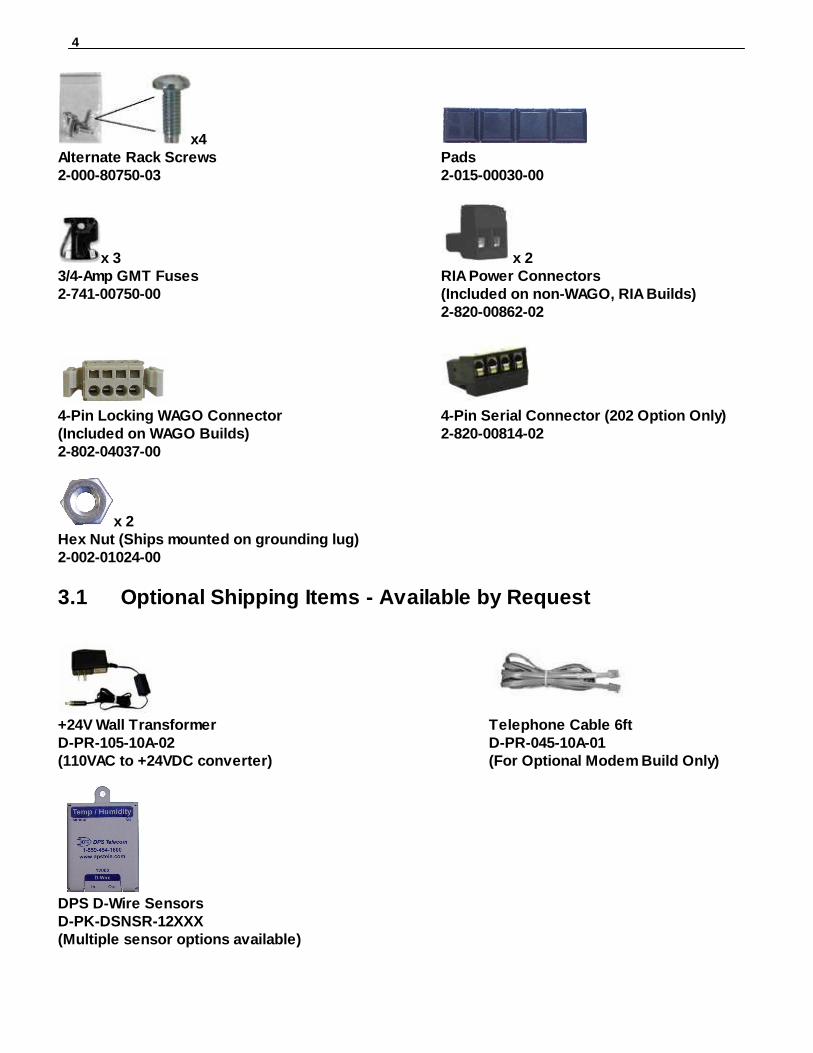
4
x4Alternate Rack Screws Pads2-000-80750-03 2-015-00030-00
x 3 x 23/4-Amp GMT Fuses RIA Power Connectors2-741-00750-00 (Included on non-WAGO, RIA Builds)
2-820-00862-02
4-Pin Locking WAGO Connector 4-Pin Serial Connector (202 Option Only)(Included on WAGO Builds) 2-820-00814-022-802-04037-00
x 2 Hex Nut (Ships mounted on grounding lug)2-002-01024-00
Optional Shipping Items - Available by Request3.1
+24V Wall Transformer Telephone Cable 6ftD-PR-105-10A-02 D-PR-045-10A-01(110VAC to +24VDC converter) (For Optional Modem Build Only)
DPS D-Wire SensorsD-PK-DSNSR-12XXX(Multiple sensor options available)

5
Installation4
Tools Needed4.1
To install the NetGuardian 480, you'll need the following tools:
Phillips No. 2 Screwdriver Small Standard No. 2 Screwdriver
PC with terminal emulator,
such as HyperTerminal
Mounting4.2
The NetGuardian 480 can be flush or rear-mounted
The NetGuardian 480 mounts in a 19" rack or a 23" rack using the provided rack ears for each size. Two rack earlocations are provided. Attach the appropriate rack ears in the flush-mount or rear-mount locations shown inFigure 6.2.1.
Note: Rack ears can be rotated 90° for wall mounting or 180º for other mounting options (not shown).

6
NetGuardian Front Panel5
NetGuardian 432 G3
NetGuardian 432 G4
NetGuardian 480 G3
NetGuardian 480 G4

7
NetGuardian Back Panel6
NetGuardian 432 G3 back panel connections
NetGuardian 432 G4 back panel connections
NetGuardian 480 G3 back panel connections
NetGuardian 480 G4 back panel connections
8
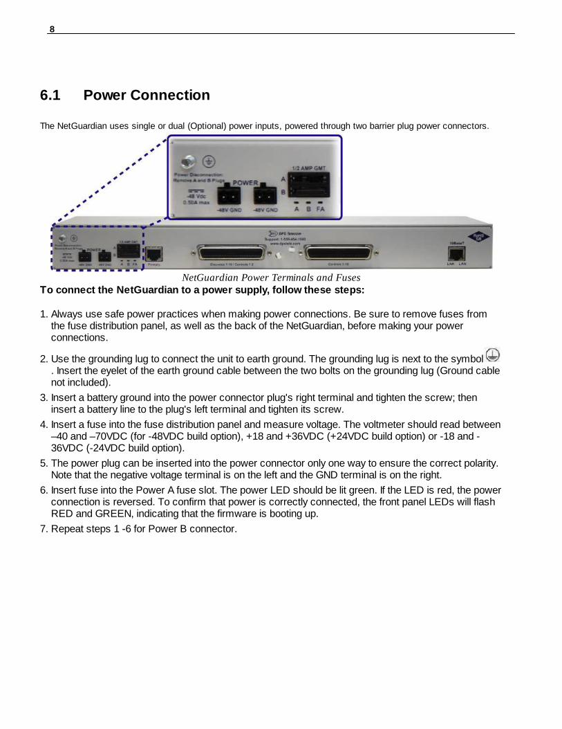
Power Connection6.1
The NetGuardian uses single or dual (Optional) power inputs, powered through two barrier plug power connectors.
NetGuardian Power Terminals and FusesTo connect the NetGuardian to a power supply, follow these steps:
1. Always use safe power practices when making power connections. Be sure to remove fuses fromthe fuse distribution panel, as well as the back of the NetGuardian, before making your powerconnections.
2. Use the grounding lug to connect the unit to earth ground. The grounding lug is next to the symbol. Insert the eyelet of the earth ground cable between the two bolts on the grounding lug (Ground cablenot included).
3. Insert a battery ground into the power connector plug's right terminal and tighten the screw; theninsert a battery line to the plug's left terminal and tighten its screw.
4. Insert a fuse into the fuse distribution panel and measure voltage. The voltmeter should read between–40 and –70VDC (for -48VDC build option), +18 and +36VDC (+24VDC build option) or -18 and -36VDC (-24VDC build option).
5. The power plug can be inserted into the power connector only one way to ensure the correct polarity.Note that the negative voltage terminal is on the left and the GND terminal is on the right.
6. Insert fuse into the Power A fuse slot. The power LED should be lit green. If the LED is red, the powerconnection is reversed. To confirm that power is correctly connected, the front panel LEDs will flash RED and GREEN, indicating that the firmware is booting up.
7. Repeat steps 1 -6 for Power B connector.

9
LAN Connection6.2
To connect the NetGuardian to the LAN, insert a standard RJ45 Ethernet cable into the 10/100BaseTEthernet port on the back of the unit. If the LAN connection is OK, the LNK LED will light SOLIDGREEN.
Serial Connection6.3
The NetGuardian has 4 build options for it's serial / dialup port. You can order your port as a Yost RS-232, RS-485, 4-wire 202 RJ45/4-pin connection, or with a dial-up modem. The serial port is locatedon the back panel.
! Hot Tip! If you are unsure of the serial port type on your NetGuardian, login to MyDPS andclick on the Product Information Search link. Type in the full part number of your unitand click the Submit button to access the specifications.
The serial port can be used for different functions:· Reach-through proxy connection for LAN-based Telnet access to switches, radios, PBXs and
other equipment. · Alarm reporting to the T/Mon Remote Alarm Monitoring System over an RS-232, 485, 202, or
dial-up modem.
Note: If the serial port is configured for alarm reporting to T/Mon, the port is not available for use as areach-through proxy port.

10
Alarm and Control Relay Connectors6.4
6.4.1 NetGuardian 432 G3 Pinouts
NetGuardian 432 G3 Alarm and Relay Connectors
The connectors for discrete alarms and control relays is the 50-pin connector on the NetGuardian 'sback panel.
NetGuardian 432 G3 Amphenol pinout.

11
6.4.2 NetGuardian 432 G4 Pinouts
NetGuardian 432 G4 Alarm and Relay Connectors
NetGuardian 432 G4 Amphenol pinouts.

12
6.4.3 NetGuardian 480 G3 Pinouts
NetGuardian 480 G3 Alarm and Relay Connectors
The connectors for discrete alarms and control relays are the two 50-pin connectors on theNetGuardian 's back panel.
NetGuardian 480 G3 Amphenol pinout.

13
6.4.4 NetGuardian 480 G4 Pinouts
NetGuardian 480 G4 Alarm and Relay Connectors
NetGuardian 480 G4 Amphenol pinouts.
Discrete Alarms6.5
To generate an alarm, tie the ALM pin to the RTN pin.

14
Optional 66 Block Connector6.6
Both of the 50-pin connectors on the back panel of the NetGuardian can be connected to DPSTelecom's optional 66 block connector. For pinout and color-code information, see the diagrams below.
Note: The 66 Block supports termination of 22 - 26 AWG (0.81 - 0.41mm) solid insulated cable or 18-19AWG (1.02 - 0.91mm) solid stripped cable. DPS recommends using 24 AWG wire (solid).
NetGuardian 480 G3
66 block connections for discretes 49-80 and control relays1-4 (left amphenol)
66 block connections for discretes 1-48 (right amphenol)

15
D-Wire Sensor Input (analogs)6.7
The port on your NetGuardian labeled "D-Wire" supports up the connection of up to 16 chained D-Wireanalog sensors. The NetGuardian powers and communicates with your D-Wire sensors via straight-through RJ-11 cables.
Connecting D-Wire SensorsUsing a 6P4C, straight-through RJ-11 cable, connect the D-Wire sensor port on the NetGuardian tothe In jack on a D-Wire sensor. Chain additional sensors to the NetGuardian (using the same straight-through cables) from the Out jack on the previous sensor to the In jack on the next (i.e. Out on sensor 4to In on sensor 5).
Pinout for D-Wire RJ-11 jacks
Note: Some sensors may consume 2 of your NetGuardian's 16 analog channels (the combined temp/humidity sensor, D-PK-DSNSR-12002, for example). Your NetGuardian can provide power to a sensorchain up to 800 feet long.
The Integrated temperature build option uses one of the maximum 16 sensors that are supported. The D-Wire line of sensors includes temp/humidity, additional analogs, discretes, and more. ContactDPS at 1-800-693-0351 for information about available D-Wire sensors.
For details about configuring your sensors though the web interface, see the Sensors section of thismanual.
6.7.1 Analog Step Sizes
Analog Step Sizes:Your Analogs are accurate to within +/- 1% of the analog range.
Analog Step Sizes and Accuracy
Input Voltage Range Resolution (Step Size) Accuracy
0-5 V .0015 V +/- .05V
5-14 V .0038 V +/- .14V
14-30 V .0081 V +/- .30V
30-70 V .0182 V +/-.70V
70-90 V .0231 V +/-.90V
Analog step sizes and accuracy

16
Quick Start: How to Connect to the NetGuardian7
Most NetGuardian users find it easiest to give the unit an IP address, subnet and gateway through thefront USB craft port (TTY interface) to start. Once these settings are saved and you reboot the unit, youcan access it over LAN to do the rest of your databasing via the Web Browser interface.
Alternative option: You can skip the TTY interface by using a LAN crossover cable directly from yourPC to the NetGuardian and access its Web Browser. See the "...via LAN" section of this chapter.
...via Craft Port (using TTY Interface)7.1
1. The simplest way to connect to the NetGuardian is over a physical cable connection between yourPC's USB port and the unit's USB craft port. Note: You must be connected via craft port or Telnetto use the TTY interface. Make sure you are using a standard A-B USB cable (this same cable iscommonly used for USB printers) to make a USB craft port connection. We'll be usingHyperTerminal to connect to the unit in the following example - however, most terminal-emulatingprograms are also compatible.

17
When you first connect the NetGuardian to your PC via USB, a "Found New Hardware" message willappear:
1. Click the "Found New Hardware" message/icon to launch the "Found New Hardware Wizard".
2. Select "Install from a list or specific location (Advanced)"3. Click "Next >"
4. Select "Search for the best driver in these locations."5. Insert NetGuardian Resource Disc (CD) into your PC.

18
6. Click "Browse"
7. Select the "Driver" folder of your NetGuardian Resource Disc (CD) and click "OK"
The following message will confirm installation of a new "USB Communications Port"
8. Click "Finish" to close the Wizard.
Now that the driver has been installed, a new COM port is being emulated on your PC. Before usinghyperterminal, you must confirm the identity of that new COM port (COM1, COM2, COM3...) in theWindows Device Manager.

19
9. Right-click the "My Computer" icon on your desktop, then click "Manage"
10.Click "Device Manager" in the left pane.

20
11.Expand the "Ports (COM & LPT)" section in the right pane. Look for "USB Communications Port(COMx)". Note the number of the COM port ("COM3" in the example above).
Now that you know which COM port to use, it's time to launch HyperTerminal (or other terminalsoftware):
12.Click on the Start menu > select Programs > Accessories > Communications >HyperTerminal.
13. At the Connection Description screen, enter aname for this connection. You may also select anicon. The name and icon do not affect your abilityto connect to the unit.
14. At the Connect To screen, use the drop-down menu to select the COM port you foundearlier in the Device Manager.

21
15. Select the following COM port options:• Bits per second: 9600• Data bits: 8• Parity: None• Stop bits: 1• Flow control: None
Once connected, you will see a blank, whiteHyperTerminal screen. Press Enter to activatethe configuration menu.
16. When prompted, enter the default username admin and password dpstelecom.NOTE: If you don't receive a prompt for youruser name and password, check the Com portyou are using on your PC and make sure youare using the cable provided. Additional cablescan be ordered from DPS Telecom.
17. The NetGuardian 's main menu will appear.Type C for C)onfig, then E for E)thernet. Configurethe unit's IP address, subnet mask, and defaultgateway.
18. ESC to the main menu. When asked ifyou'd like to save your changes, type Y for Y)es.Reboot the NetGuardian to save its newconfiguration.

22
Now you're ready to do the rest of your configuration via LAN. Plug the NetGuardian into your LAN andsee the "Logging On to the NetGuardian " section to continue databasing using the Web Browser.
NOTE: Hold down push button for 20 seconds to bypass TTY login.
...via LAN7.2
Connection through Ethernet port
To connect to the NetGuardian via LAN, all you need is the unit's IP address (Default IPaddress is 192.168.1.100).
If you DON'T have LAN, but DO have physical access to the NetGuardian , connect using a LANcrossover cable. NOTE: Newer PCs should be able to use a standard straight-through LAN cable andhandle the crossover for you. To do this, you will temporarily change your PC's IP address and subnetmask to match the NetGuardian's factory default IP settings. Follow these steps:
1. Get a LAN crossover cable and plug it directly into the NetGuardian 's LAN port.
2. Look up your PC's current IP address and subnet mask, and write this information down.
3. Reset your PC's IP address to 192.168.1.200. Contact your IT department if you are unsure howto do this.
4. Reset your PC's subnet mask to 255.255.0.0. You may have to reboot your PC to apply your
23
changes.
5. Once the IP address and subnet mask of your computer coincide with the unit, you can accessthe NetGuardian via a Telnet session or via Web browser by using the unit's default IP addressof 192.168.1.100.
6. Provision the NetGuardian with the appropriate information, then change your computer's IPaddress and subnet mask back to their original settings.
Now you're ready to do the rest of your configuration via LAN. Plug your NetGuardian into your LAN and see the "Logging On to the NetGuardian " section to continue databasing using the Web Browser.
TTY Interface8
The TTY interface is the NetGuardian's built-in interface for basic configuration. From the TTY interface, you can:· Edit the IPA, subnet, and gateway · Set DCP info for T/Mon polling· Configure primary port · Ping other devices on the network· Set unit back to factory defaults · Debug and troubleshoot
For more advanced configuration tools, please use the Web Browser Interface.
For Telnet, connect to the IP address at port 2002 to access the configuration menus after initial LAN/WAN setup. Telnet sessions are established at port 2002, not the standard Telnet port as an added security measure.
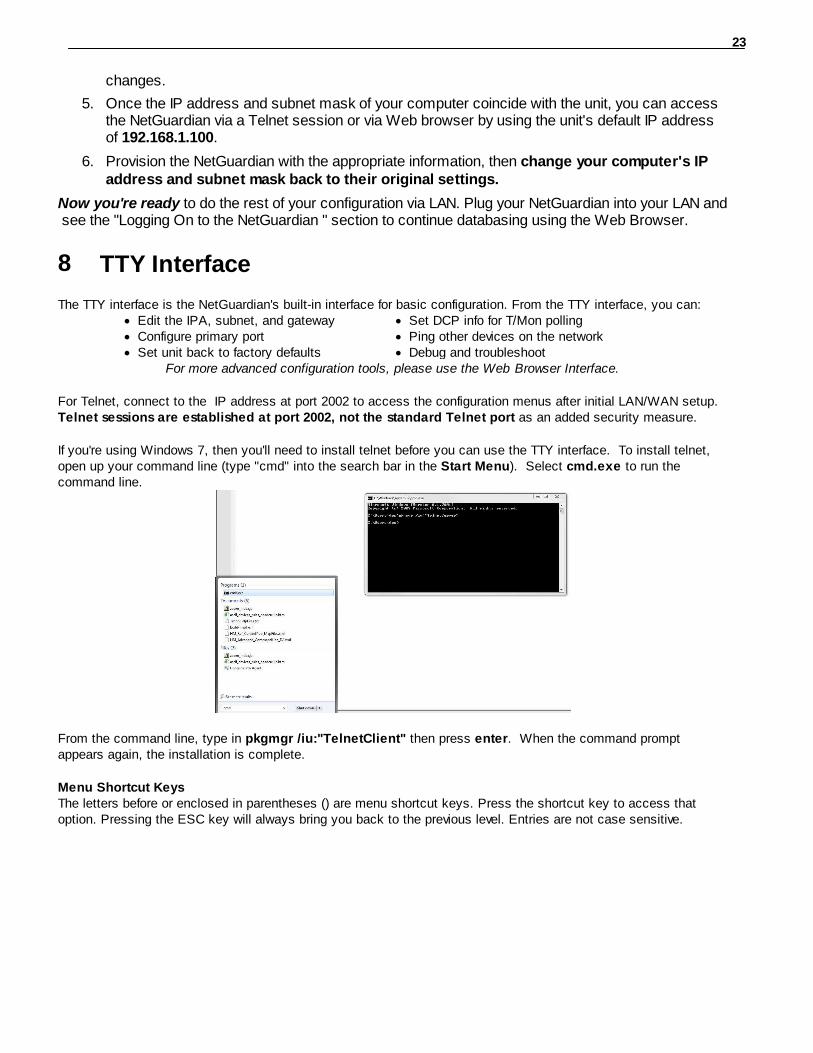
If you're using Windows 7, then you'll need to install telnet before you can use the TTY interface. To install telnet,open up your command line (type "cmd" into the search bar in the Start Menu). Select cmd.exe to run thecommand line.
From the command line, type in pkgmgr /iu:"TelnetClient" then press enter. When the command promptappears again, the installation is complete.
Menu Shortcut KeysThe letters before or enclosed in parentheses () are menu shortcut keys. Press the shortcut key to access thatoption. Pressing the ESC key will always bring you back to the previous level. Entries are not case sensitive.

24
Configure Serial Port via TTY8.1
1. To enter configuration setting for the Serial Port, login to the TTY interface and press C)onfig > s(E)rial.
2. Press the hot keys to toggle through the following options. (* Indicates default settings:) NOTE: Default settings may not reflect the primary interface that shipped in the unit.
· Port Type: 232*, 485· Baud: 9600*, 57600, 19200, 9600, 4800, 2400, 1200· Parity: None*, even, odd· Stop bits: 1*, 2
3. Set the RTS head / tail (Carrier time) Suggested settings are: 0,0 if using RS232.

25
Quick Turn Up9
The next sections of this manual will walk you through some of the most common tasks for using the NetGuardian.You will learn how to send email notifications, and send SNMP traps to your alarm master - all using the Webbrowser. For details on entering your settings into each Web browser menu, the section "Provisioning Menu FieldDescriptions" section.
How to Send Email Notifications9.1
1. Click on the Notifications button in the Provisioning menu. You can setup as many as 8 different notifications.Begin the setup "wizard" by clicking Edit for a notification number. In this example, we'll setup Notification 1 to sendemails.
2. At the Notification Setting screen, use the drop down box to set what events to use for this notification. Now,select the Send Email button and click Save and Next.
3. At the Email Notification screen, you'll enter your email server settings. Enter the IP address or Host Name ofyour email server. Note: if using Host Name, make sure that DNS Servers settings are configured. Enter the PortNumber (usually 25) and the "To" Email Address of the technician that will receive these emails. If authenticationis required, chose the type and fill in the necessary fields. Click Next.
4. At the Schedule screen, you'll select the exact days/times you want to receive email notifications. You can settwo schedules per notification. For example, you may want to receive notifications at certain times during the week,and at different hours on the weekend. Use the check boxes to select the days of the week, and select the timefrom the drop down menus. Click Finish. To try a test notification, click the Test button (See next step.)

26
5. If you chose to test the email notification you've just setup, you will prompted with a pop up . Click OK to send atest email alarm notification. Confirm all your settings by checking your email to see if you've received it. NOTE: Thistest only means that your notification settings are correct, but you still need to assign the notification to an alarmpoint. See the next step.
6. Now you will associate this notification to an alarm (system, base, analog, etc.) You have 8 notification devicesavailable to use. In the image below, you might assign Notification Device 1 to Alarm 1. This means that youwould receive an email notification when "Temperature Threshold 1" (Alarm Point 1) occurs. Remember thatNotification #1 in the Notifications menu corresponds to the first "Notifications" column of check boxes. (Notification#2 is the second column, and so on until Notification #8)

27
How to Send SNMP Traps9.2
1. Click on the SNMP button in the Provisioning menu. Enter the SNMP GET and SNMP SET community stringsfor your network, then click Save. The typical SNMP SET and GET community strings for network devices is"public". As an added security measure, we've made our default "dps_public".
2. Click on the Notifications button in the Provisioning menu. You can setup as many as 8 different notifications.Begin the setup "wizard" by clicking Edit for a notification number. In this example, we'll setup Notification 1 to sendSNMP traps to your alarm master.
3. At the SNMP Notification screen, you'll enter your network's SNMP settings. Enter the IP address of yourSNMP Trap Server. Enter the Trap Port Number (usually 162) and the Trap Community password. Click Saveand Next.
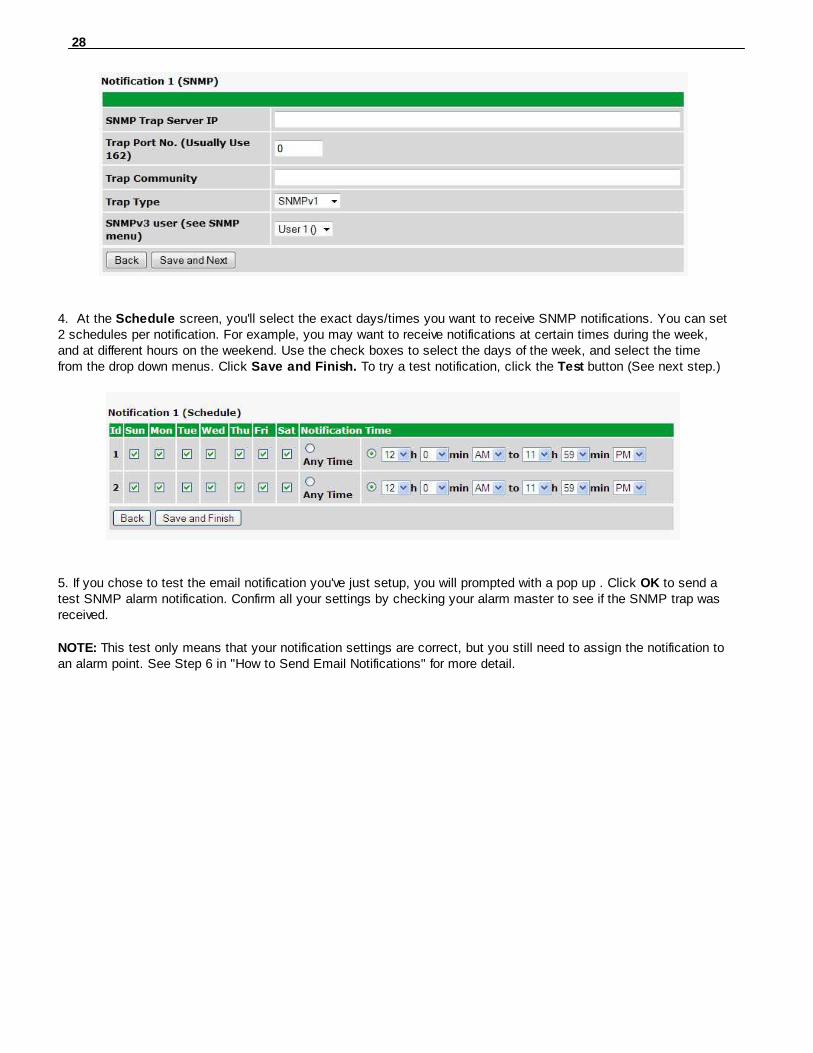
28
4. At the Schedule screen, you'll select the exact days/times you want to receive SNMP notifications. You can set2 schedules per notification. For example, you may want to receive notifications at certain times during the week,and at different hours on the weekend. Use the check boxes to select the days of the week, and select the timefrom the drop down menus. Click Save and Finish. To try a test notification, click the Test button (See next step.)
5. If you chose to test the email notification you've just setup, you will prompted with a pop up . Click OK to send atest SNMP alarm notification. Confirm all your settings by checking your alarm master to see if the SNMP trap wasreceived.
NOTE: This test only means that your notification settings are correct, but you still need to assign the notification toan alarm point. See Step 6 in "How to Send Email Notifications" for more detail.

29
Provisioning Menu Field Descriptions10
NetGuardian configuration is performed from the Provisioning menus, the menu options in green on the left-side ofthe web interface. The following pages provide a brief description of the options available in each menu.
Saving Configuration Changes to the NetGuardian:At the bottom of each screen you access from the Provisioning Menu, you will see a Save button. Clicking Savewill cache your changes locally. The web interface will then prompt you to either Write your changes to the unit orReboot the unit for changes to take effect in the top-left corner of your browser. The relevant options will behighlighted in the Device Access options.
Note: If the unit prompts you to both Write changes to the unit and Reboot, you will Write your changes first. Rebooting without writing to the unit (if a Write is required) will cause you to lose your configuration changes.
Status messages on the NetGuardian Device Access menu, inform you how to implement your changes
The control menu highlights items that must be completed for your changes to take effect

30
System10.1
From the Provisioning > System menu, you will configure and edit the global system, call, T/Mon and controlsettings for the NetGuardian.
The Provisioning > System menu
Global System SettingsName A name for this NetGuardian unit. {Optional field)
Location The location of this NetGuardian unit. {Optional field)
ContactContact telephone number for the person responsible for this NetGuardian unit.{Optional field)
Sound on COS Checking this box enables Sound on COS when viewing the Alarms, Sensors, PingTargets, or System Alarms page under the Monitor menu.
DCP Responder Settings (For use with T/Mon)Disable DCP, DCP over
LAN / SerialSelect one of these 3 options to send DCP protocol over LAN, serial, ordisable DCP completely.
DCP Unit ID User-definable ID number for the target unit (DCP Address).DCP Unit Protocol Drop-down menu of available protocols for use with DCP Address.DCP over LAN port Enter the DCP port for the target unit. (UDP/TCP port)
LAN Protocol Drop-down menu of available protocols for use over LAN.Expansions Select the number of expansion units connected to the NetGuardian.
System ControlsGet History Download a log of all configured analog and sensor values.
Get Alarm Log Download a log of the device's recent alarm history.Erase History Erase the log of all configured analog and sensor values.

31
User Profiles10.2
Clicking User Profiles gives you access to modify the default username and password, and to edit the administratorprofile and create up to 9 additional unique user profiles, each with different access rights to the NetGuardian 480'sweb interface.
Configure access privileges for users in the User Profile screen
To create or edit any of the 10 user profiles (including the Admin), click the Edit button. From there, you canchange all configurable settings for a user profile.
User Profile
Suspend this Profile If this box is checked, the profile will not be able to access the NetGuardian.
Username Enter a username or a user description
Password Enter a unique user password Note: All passwords are AES 128 encrypted.
Confirm Password Re-enter the password.
Access Rights
Check all Enables all Access Rights
Edit logon profiles Enables the user to add/modify user profiles and password information.
Write Config (changeunit configuration)
Enables the user to change the unit config by accessing the Write feature in thecontrol menu.
View monitor pages Allows the user to access Monitor menu options.
Send relay commands Allows the user to send commands to operate the device's control relays.
TTY access (access viaCraft port or via Telnet)
Grants the user access to the unit via TTY interface (via craft or telnet).
Initialize config tofactory defaults
Allows the user to use the Initialize option in the Device Access menu, resetting theNetGuardian to factory default settings. All user settings will be lost.
Upload new firmware,or config
Allows the user to upload firmware or backed-up configuration files.
Get audit log Allows the user to access the Audit Log (Get Log command).
Purge (delete) audit log Allows the user to deletes the existing audit log.
Get (backup) config Backs-up all user profile configuration settings.
Get and delete analoghistory
Allows the user to access and delete the analog and sensor history.
User profile field descriptions

32
Ethernet10.3
The Edit > Ethernet menu allows you to define and configure Ethernet settings.
The Provisioning > Ethernet menu
Ethernet Settings
MAC Address Hardware address of the NetGuardian. (Not editable - For reference only.)
Host Name
Used only for web browsing. Example: If you don't want to remember this NetGuardian'sIP address, you can type in a name is this field, such as "MyNetGuardian". Once yousave and reboot the unit, you can now browse to it locally by simply typing in"MyNetGuardian" in the address bar. (no "http://" needed).
Enable DHCP
Used to turn on Dynamic Host Connection Protocol. NOT recommended, because theunit is assigned an IP address from your DHCP server. The IP you've already assigned tothe unit becomes inactive. Using DHCP means the unit will NOT operate in a T/Monenvironment.
Unit IP IP address of the NetGuardian.
Subnet MaskA road sign to the NetGuardian, telling it whether your packets should stay on your localnetwork or be forwarded somewhere else on a wide-area network.
GatewayAn important parameter if you are connected to a wide-area network. It tells the
NetGuardian which machine is the gateway out of your local network. Set to255.255.255.255 if not using. Contact your network administrator for this info.
DNS Server 1 Primary IP address of the domain name server. Set to 255.255.255.255 if not using.
DNS Server 2 Secondary IP address of the domain name server. Set to 255.255.255.255 is not using.
Advanced TCP Settings
Force Max TCPWindow Size
The defined TCP window size is used. (For low-bandwidth networks)
Maximum TCPWindow Size
Sets the TCP receive window size.
Note: DNS Server settings are required if a hostname is being used for ping targets.

33
RADIUS10.4
RADIUS (Remote Authentication Dial In User Service) is an industry-standard way to manage logins to manydifferent types of equipment in one central location. The NetGuardian connects to your central RADIUS server. Everytime a device receives a login attempt (usually a username & password), it requests an authentication from theRADIUS server. If the username & password combination is found in the server's database, an affirmative "accessgranted" reply is sent back to the unit device, allowing the user to connect.
Fig. 2.1. RADIUS configuration screen
Fig. 2.2. RADIUS server prompt for Usernameand Password.
Global Settings
Retry Enter the number of times the RADIUS server should retry alogon attempt
Time-out Enter in the number of seconds before a logon request is timedout
Servers 1 / 2
IPA Enter the IP address of the RADIUS server
Port Port 1812 is an industry-standard port for using RADIUS
Secret Enter the RADIUS secret in this field
After successfully entering the settings for the RADIUS server, the NetGuardian Web Browser will prompt users forboth a Username and Password, which will be verified using the information and access rights stored in the RADIUSdatabase.
RADIUS logons are case-sensitive. If the RADIUS server is unavailable or access is denied, the master passwordwill work for craft port access only. Also, the "dictionary.dps" files (included on the Resource Disk) needs to beloaded on the RADIUS server for access-right definition. If RADIUS is enabled on the NetGuardian, the localauthentication will not be valid.

34
Serial Port10.5
The Provisioning > Serial Port menu allows you to change settings depending on the port type of yourNetGuardian. From this menu, you can select a mode of operation and enable reach-through serial port functionality.
The Provisioning > Serial Ports menu
LocationReminder that the primary serial port is located on the back of the NetGuardian chassis.
Port Configuration
Port TypeSelect the serial port for your build of the NetGuardian.Choose from 232, 485...
Baud, Parity, and Stop Bits Select the appropriate settings from the drop-down menu.
RTS HeadOnly used if your NetGuardian was built with a 202 modem.The most commonly used value is 30.
RTS TailOnly used if your NetGuardian was built with a 202 modem.The most commonly used value is 10.
Reach-Through
Enable Reach-through
Checking this box enables the port to be used as a terminalserver. Most commonly used to Telnet through the port overLAN to a hub, switch, or router. From a command prompt,type the following (note the spaces between each entry):
telnet [IP address] [port]Example: telnet 192.168.1.100 3000
Port Port number used for reach-through to a serial device.
TypeSelect TCP or UDP traffic to be passed through to a serialdevice.

35
SNMP10.6
The Provisioning > SNMP menu allows you to define and configure the SNMP settings.
SNMP Menu
Global Settings
Get Community Community name for SNMP requests.
Set Community Community name for SNMP SET requests.
Read and WriteAccess
This field defines how the NetGuardian may be accessed via SNMP. This can be set tothe following:· Access Disabled- Restricts all access to unit via SNMP· SNMPv2c only- Allows SNMPv2c access only· SNMPv2c and SNMPv1-Only- Allows SNMPv1 and SNMPv2c access· SNMPv3, SNMPv2c and SNMPv1- Allows SNMPv3, SNMPv2c and SNMPv1 access
Fields in the Provisioning > SNMP settings

36
Notifications10.7
From the initial Provisioning > Notifications menu, you will see which of the notifications are enabled, their server,and schedule. Click on the Edit link for one of the notifications to begin configuration.
Once you've chosen which notification you want to setup, check the Enable Notification to turn it "on." Thenchoose a notification method, either email, SNMP, voice call, or TRIP Dialup (T/Mon).
10.7.1 Notification Settings
Email Notification Fields
Editing Email Notification Settings
Email Notification
SMTP Server IP orHost Name
The IP address of your email server.
Port Number The port used by your email server to receive emails, usually set to 25.
Use SSL
Check this box to use SSL encryption. Currently this feature has been testedwith Gmail. To send with Gmail SMTP server, do the following:· SMTP Server IP or Host Name should be set to "smtp.gmail.com" · Port number must be set to 465. · SMTP authentication radio button must be selected. · User name and password (below under "How to Authenticate") are the user
name and password for the Gmail account in use.
"From" E-mail AddressDisplays the email address (defined in the Edit menu > System) that theNetGuardian will send emails from. Not editable from this screen.
"To" E-mail AddressThe email address of the person responsible for this NetGuardian, who willreceive email alarm notifications.
User Name User name for the Gmail account being used.
Password Password for the Gmail account being used.

37
SNMP Notification Fields
Editing SNMP notification settings
SNMP Notification
SNMP Trap Server IP The SNMP trap manager's IP address.
Trap Port No.The SNMP port (UDP port) set by the SNMP trap manager to receivetraps, usually set to 162.
Trap Community Community name for SNMP TRAP requests.
Trap TypeIndicate whether you would like to send SNMP v1, v2c, v2c inform, or v3traps.
10.7.2 Schedule
The notifications scheduling menu is where you will tell the NetGuardian exactly which days and times you want toreceive alarm notifications. You set 2 different schedules for each.
The Schedule creation screen
Notification SchedulingDays of the week From either Schedule 1 or 2, check which days you want to receive notifications.
Any TimeSelect this is if you want to receive alarm notifications at any time for the day(s)you've selected.
Notification TimeTells the unit to only send notifications during certain hours on the day(s) you'veselected.

38
Alarms10.8
Discrete alarms are configured from the Provisioning > Alarms and Provisioning > Exp. Alarms menus.Descriptions for the alarm points, polarity (normal or reversed) and notification type(s) are defined from this menu. You also have the option to use Basic or Advanced configuration methods, explained in this section.
The Provisioning > Alarms menu
The Provisioning > Exp. Alarms menu (NetGuardian 480 only)
Basic Alarm Configuration
ID Alarm ID number.
Description User-definable description for the discrete alarm point.
Rev (Reverse)Reverse: Check this box to reverse the polarity of the alarm point. Leaving this optionun-checked means a normally open contact closure is an alarm. When polarity isreversed, a normally closed alarm point is clear when closed.
Notification DevicesCheck which notification device(s), 1 through 8, you want to send alarm notificationsfor that alarm point.
Advanced Alarm Configuration (Advanced>>)
On SetUser-definable description (condition) that will appear for the discrete alarm input onSet. Example: "Alarm".
On ClearUser-definable description (condition) that will appear for the discrete alarm input onClear: "Example: "Alarm Cleared".
Qual. Time (QualificationTime)
The length of time that must pass, without interruption, in order for the condition to beconsidered an Alarm or a Clear.
Qual. Type (QualificationType)
Allows you to choose whether you want to apply the Qualification Time to the alarmSet, Clear, or Both.

39
Controls10.9
The NetGuardian control relays can be configured in the Provisioning > Controls and Provisioning Exp. Controlsmenus. You can enter your own description for these relays and designate them to a notification device(s).
The Provisioning > Exp. Controls screen
Basic Controls Configuration
ID ID number for the control relay.
Description User-definable description for the NetGuardian's control relay.
Momentary TimeControl on time (in milliseconds) when you execute the MOM command. Max limit of600 seconds.
Notification DevicesCheck which notification device(s), 1 through 8, you want to send alarm notificationsfor the control relay.

40
10.9.1 Derived Controls
The NetGuardian's derived controls can be configured in the Edit > Controls screen. Each control can be configuredfor derived control. Click on Detail to show the derived controls setting. Enter in a derived control equation into theDerived Description field. Click on Parse to issue a parse command. The parse command is a test that will attemptto parse the derived control equation. It will return with a "Parse Successful!" or "Parse FAILED!" message. If "ParseFAILED!" is returned, there is an error in the syntax of the equation.
Configure derive Controls in the Edit menu > Controls screen > Details > Derived Description
_OR : Set the current operation to OR._AN : Set the current operation to AND._XR : Set the current operation to XOR.
D : Tag to change the active display number.. : Used like a comma to delimit numbers.- : Used to specify a range of points.
Spaces included here are for readability purposes only.
! Hot Tip!
· Precedence of the operations are always left to right.
· All number references can either be one or two digits.
_OR D1.3-5 is logically equivalent to (1.3 || 1.4 || 1.5)
_AN D 1.3-5 D2.6 _OR D3.7 is logically equivalent to ((1.3 && 1.4 && 1.5 && 2.6) || 3.7)
_OR D01.03-05 D02.06 _AN D02.07 D03.10.-12 is logically equivalent to ((1.3 || 1.4 || 1.5 || 2.6&&(2.7 && 3.10 && 3.12))

41
_AN D1.3-5D2.6_OR.7D3.10.12 is logically equivalent to ((1.3 && 1.4 && 1.5 && 2.6 ) || 2.7 || 3.10 ||3.12))
10.9.2 Derived Expansion Controls
Derived expansion controls have the same functionality as derived controls. They are used for the expansion unitsuch as the NetGuardian E16 DX G2.
Configure derive Controls in Provisioning > Expansion Controls

42
Sensors10.10
D-Wire SensorsThe NetGuardian supports up to 16 daisy-chained D-Wire sensors via its D-Wire input. Sensors connected to theNetGuardian will appear on the web interface. The background color of the ROM field informs the user of the sensor'sconfiguration state.
Also the NetGuardian's first D-Wire sensor used to monitor the internal temperature. The internal temperature sensormeasures a range of -40° F to 180° F (-40° C to 82.2° C) within an accuracy of about ± 2°.
Basic configuration for the NetGuardian's D-Wire temperature sensors can be accomplished from the Provisioning> Sensors menu. From this screen, you can configure D-Wire sensors, select notification devices, and setthresholds.
The Provisioning > Sensors menu
Basic Sensor Configuration
ID Sensor ID number.
ROM ID
The ID number found on the sticker of the temperature sensor node. YourNetGuardian will automatically detect the sensor ID when you plug a sensor into theunit. The color of the sensor ID field will tell you the status of the connected sensor.Green - The sensor is connected and properly configured.Yellow - The sensor is connected but has not yet been configured (fill in yourconfiguration fields and click Save to configure the sensor).Red - The sensor is not detected and configured (i.e. a previous configured sensor isno longer connected).Blue - The sensor is not supported by the NetGuardian.To reconfigure or disable the Sensor ID, simply delete any data in this field and click Save.The unit will refresh the sensor ID on that channel.
Description User-definable description for the sensor channel.
Parse Checks to see if the Description field contains a valid derived equation.
Notification DevicesCheck which notification device(s), 1 through 8, you want to send alarm notificationsfor that alarm point.

43
Advanced Sensor Configuration (Details>>)
Record FreqThe amount of time, in minutes (min) or seconds (s), between each recorded sensorvalue.
DeadbandThe amount (in native units) that the channel needs to go above or below a thresholdin order to cause an alarm.
Qual Time (QualificationTime)
The length of time that must pass, without interruption, in order for the condition to beconsidered an Alarm or a Clear.
Qual. Type (QualificationType)
Allows you to choose whether you want to apply the Qualification Time to the alarmSet, Clear, or Both.
ThresholdsThese settings are set to indicate the severity of the alarm depending on whichthreshold values have been passed. Enter values for Major Under (MjU), Minor Under(MnU), Minor Over (MnO), and Major Over (MjO).
Analog Gauge TypeSelect the color-coded gauge that best represents your data. Selecting None willdisable the analog gauge and only a numerical representation of the value will bedisplayed under Monitor > Sensors.
Note: Before plugging in any additional D-Wire Sensors, set up the internal sensor.
Script SensorsA Script Sensor can be setup by entering a script type in the sensor ID field. The following types are currentlysupported:
~count - The equation will be evaluated continuously. If the evaluation changes at any point, the sensor's valueincreases by an increment of 1. This mode can be useful for counting the number of times a discrete inputtoggles.
Evaluation Sensor; every tenth of a minute (6 seconds).~evalMt - The equation is evaluated every 6 seconds and its result becomes the sensor's value.
Evaluation Sensor; every minute.~evalMn - The equation is evaluated every 60 seconds and its result becomes the sensor's value.
Interval counter.
Interval Sensor~intCnt - Sensor value will increment when the associated input's pulse length (high or low) is within a setinterval. Example: D5 V1000>V60000< means the sensor value will increment when a 1ms to 60ms pulseis detected on Discrete Input 5. This is useful for frequency detection/tracking.
A Script Sensor is configured to evaluate Reverse Polish Notation equations. A data token in an equation canrepresent a discrete alarm, analog reading, sensor reading, relay status, system alarm status, or a constant value. The format for a token in an equation must be a data type followed by an index (for example: Discrete Input 1 in anequation would be represented as "d1", Analog Channel 3 would be "a3", etc.). Each token is typically followed byanother token or an operator. The equations are entered in the description field for the Script Sensor.
Valid data types:
d Discrete Input
a Analog Channel
r Relay State
n Sensor
v Positive Integer Constant
s System Alarm

44
Valid operations:
+ Addition
- Subtraction
* Multiplication
/ Division1
> Greater than
< Less than
| Conditional Halt2
1. Division is NOT executed if the denominator's absolute value is less than 1!2. An equation is evaluated until it reaches the Conditional Halt. If the running value at that point is zero, then theevaluation stops, otherwise the evaluation continues as a new equation.
How equations are evaluated:Calculations are performed from left-to-right until the end of the equation is reached. As the equation is parsed, eachtoken's value is pushed onto a stack until an operator is found. When an operator is found, the previous 2 values arepopped from the stack and are used to perform the operation (the first item popped is the SECOND operand). Theresult of the operation is then pushed onto the stack. This repeats until the end of the equation is reached. Anequation is valid only if there is exactly ONE item left in the stack when the end of the equation is reached.
Example of how an equation is evaluated:
Equation: a8 a5 a6 + * a4 -Input Operation Stack Comment
a8 Push value a8
a5 Push value a5a8
a6 Push value a6a5a8
+ Add (a5+a6)a8
Pop a6 and a5, add them, push result to stack
* Multiply a8*(a5+a6) Pop (a5+a6) and a8, multiply them, push result to stack
a4 Push value a4a8*(a5+a6)
- Subtract a8*(a5+a6) - a4 Pop a4 and a8*(a5+a6), subtract them, push result to stack
In this example, after the subtraction there is only ONE item left in the stack (which is the result of all of theprevious computations), mak ing this a valid equation.

45
Ping Targets10.11
The Provisioning > Ping Targets menu allows you to configure the Description, IP Address, and NotificationDevices for each of your ping targets.
The Provisioning > Ping Targets menu
Provisioning Ping TargetsID ID number for the ping target.
Enab Check this box to enable the ping target.Description User-definable description for the ping target.
Server (IP orHostname)
IP address or hostname of the device you would like to ping.
Notification DevicesCheck which notification device(s), 1 through 8, you want to send alarmnotifications for ping target.

46
Modbus Devices10.12
The Provisioning > Modbus Devices
47
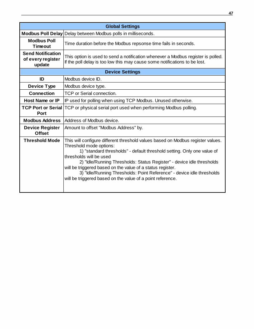
Global Settings
Modbus Poll Delay Delay between Modbus polls in milliseconds.
Modbus PollTimeout
Time duration before the Modbus repsonse time fails in seconds.
Send Notificationof every register
update
This option is used to send a notification whenever a Modbus register is polled.If the poll delay is too low this may cause some notifications to be lost.
Device Settings
ID Modbus device ID.
Device Type Modbus device type.
Connection TCP or Serial connection.
Host Name or IP IP used for polling when using TCP Modbus. Unused otherwise.
TCP Port or SerialPort
TCP or physical serial port used when performing Modbus polling.
Modbus Address Address of Modbus device.
Device RegisterOffset
Amount to offset "Modbus Address" by.
Threshold Mode This will configure different threshold values based on Modbus register values.Threshold mode options:
1) "standard thresholds" - default threshold setting. Only one value ofthresholds will be used
2) "Idle/Running Thresholds: Status Register" - device idle thresholdswill be triggered based on the value of a status register.
3) "Idle/Running Thresholds: Point Reference" - device idle thresholdswill be triggered based on the value of a point reference.

48
Modbus Registers10.13
The Provisioning > Modbus Registers

49
Basic Configuration
ID Modbus register ID
Modbus Device Modbus device settings used when polling.
Description User0definable description for the Modbus register.
Notifications Check which notification device(s), 1 through 8, you want to send alarmnotifications for that Modbus register.
Details
Function Code
Modbus function code to use when polling device
Event Qualification
Qual. Time - Threshold must be crossede for this length of time before alarms is triggered. (set to 0to deactivate)
Qual. Type - Determines which actions Qual Time applies to.
Recording Settings
Stable Frequency Frequency used when logging response history.
Register Attributes
Register Number Register to be polled.
Number of Bits Number of bits used to mask the response value.
Integer/Float Interpret response value as an integer for a float.
Unsigned/Signed Interpret the response value as signed or unsigned.
Byte Order Byte ordering of response from Modbus device.
Scaling Scaling factor that the response value is multiplied by.
Units Units displayed with the response value.
Thresholds
MjU (Major Under)MnU (Minor Under)MnO (Minor Over)MjO (Major Over)
Threshold settings that, when crossed, will prompt the NetGuardian to set analarm. Recorded values less than an under value or greater than an over valuewill cause alarms.NOTE: If the user has one of the Idle/Running threshold modes selected inDevice settings then there will be two sets of thresholds displayed here. IfStandard Thresholds is selected there will only be one.
Deadband The additional qualifying calue the NetGuardian requires above/below youralarm thresholds in order to set an alarm.
50
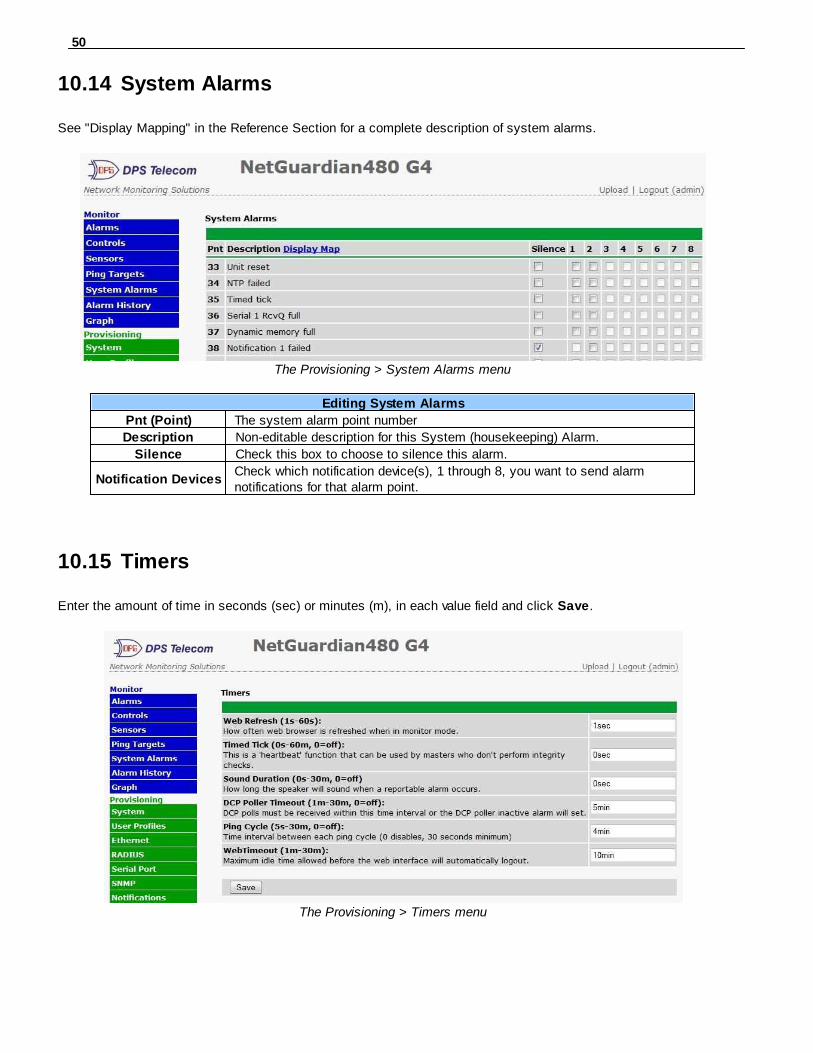
System Alarms10.14
See "Display Mapping" in the Reference Section for a complete description of system alarms.
The Provisioning > System Alarms menu
Editing System Alarms
Pnt (Point) The system alarm point number
Description Non-editable description for this System (housekeeping) Alarm.
Silence Check this box to choose to silence this alarm.
Notification DevicesCheck which notification device(s), 1 through 8, you want to send alarmnotifications for that alarm point.
Timers10.15
Enter the amount of time in seconds (sec) or minutes (m), in each value field and click Save.
The Provisioning > Timers menu

51
Date and Time10.16
The Provisioning > Date and Time menu
Unit TimeDate Set today's date.Time Set the current time.
Automatic Time Adjustment (NTP)Enable NTP Check this box to enable Network Time Protocol.
NTP Server Address or Host NameEnter the NTP server's IP address or host name, then click Sync.Example: us.pool.ntp.org. Note: Make sure to configure DNS before usinghost name instead of IP address.
Time Zone Select your time zone from the drop-down menu.Adjust Clock for Daylight Savings Time (DST)
Enable DST Check this box to have the NetGuardian 480 observe Daylight Savings.Start Day Select the month, weekday, and time when Daylight Savings will begin.End Day Select the month, weekday, and time when Daylight Savings will end.

52
Monitoring via the Web Browser11
Alarms11.1
This selection provides the status of the base and expansion alarms by indicating if an alarm has been triggered.Under the State column, the status will appear in red if an alarm has been activated. The status will be displayed ingreen when the alarm condition is not present.
Click on Alarms or Exp. Alarms in the Monitor menu to see if any discrete alarms have been triggered.
Expansion Alarm MonitoringID Alarm ID number.
Description User-definable description for the discrete alarm point.State The current state of the alarm. (Clear or Alarm)
53
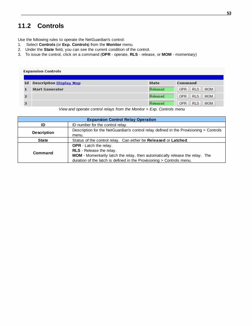
Controls11.2
Use the following rules to operate the NetGuardian's control: 1. Select Controls (or Exp. Controls) from the Monitor menu. 2. Under the State field, you can see the current condition of the control.3. To issue the control, click on a command (OPR - operate, RLS - release, or MOM - momentary)
View and operate control relays from the Monitor > Exp. Controls menu
Expansion Control Relay Operation
ID ID number for the control relay.
DescriptionDescription for the NetGuardian's control relay defined in the Provisioning > Controlsmenu.
State Status of the control relay. Can either be Released or Latched.
Command
OPR - Latch the relay.RLS - Release the relay.MOM - Momentarily latch the relay, then automatically release the relay. Theduration of the latch is defined in the Provisioning > Controls menu.

54
Sensors11.3
This selection provides the status of the system's analog channels by indicating if an alarm has been triggered. The Monitor > Sensors screen provides a description of each analog channel, the current reading, the units being read,and alarm conditions (major under, minor under, major over, minor over) according to your temperature settings. Ifconfigured under Provisioning > Sensors, your analog values will be displayed as a graphical gauge. SelectingTable View will display a non-graphical interface of your values.
The Monitor > Sensors menu

55
Ping Targets11.4
Ping Targets can be viewed by going to Monitor > Ping Targets. Here you can view the state (either Clear orAlarm) for each of your configured Ping Targets.
View the status of Ping Targets from the Monitor > Ping Targets menu.

56
System Alarms11.5
System alarms are not-editable, housekeeping alarms that are programmed into NetGuardian. The Monitor >System Alarms screen provides the status of the system alarms by indicating if an alarm has been triggered. Underthe State column, the status will appear in red if an alarm has been activated. The status will be displayed in greenwhen the alarm condition is not present.
See "Display Mapping" in the Reference Section for a complete description of system alarms.
View the status of System Alarms from the Monitor > System Alarms menu.
Monitor > Alarm History menu

57
Graph11.6
The Graph section of the monitor menu lets you build a graph of past sensor measurements, which gives you avisual indication of data over time and points out trending values. To create your Graph, specify the Channel( Sensors 1-32), Group Interval (1-120 minutes, hours, days, or weeks), the Group Function (Average, Min, Max),and Start & End Times. Once you have entered all of the desired values, click "Build Graph."
Provision the Channels, Group Interval, Group Function and more - all from theGraph Parameters section of the web browser interface.

58
Your graph will appear on the next screen. This graph is Adobe Flash-based and allows you to mouse over the linesto quickly view measurements (date, time, and value) within their context of the overall graphing trend. Below thegraph is a full textual list of all indexed points with their dates and values.
Specify your parameter values and build an interactivegraph based on the alarm point history.

59
Device Access Descriptions12
The Device Access options, listed in pink on the left side of the web interface, provide options for generating reports,updating the NetGuardian's firmware, and rebooting the unit. Click any of the options under Device Access toperform the desired action.
The control menu is located in the bottom left of the web interface
Device Access Option DescriptionBackup Config Backs up the units configuration settings
Read Reads a configuration file from the unit
WriteCommits all changes made in the web interface to the NetGuardian's non-volatilememory
Initialize Sets the unit's configuration to factory default valuesGet Log Opens the NetGuardian's event log in Notepad (or another plain text editor).
Purge Log Deletes the NetGuardian's event log history.Reboot Reboots the NetGuardian.

60
Firmware Upgrade13
To access the Firmware Load screen, click on the Upload link in the top right corner.
At the Firmware Load screen, simply browse for the firmware update you've downloaded from www.dpstele.comand click Load.
Browse for downloaded firmware upgrade

61
Reference Section14
Front and Back Panel LEDs14.1
Front panel LEDs
LED Status Description
StatusBlinking Green NetGuardian application running
Blinking Red Boot Loader is running
Craft Flashing Green NG data transmit over craft port
Flashing Red NG data receive over craft port
SerialBlinking Green Back-panel serial port transmit
Blinking Red Back-panel serial port receive
LAN Blinking Green LAN activity
AlarmFlashing Red New alarm
Solid Red Standing alarm acknowledged
Relay Solid Green 1 or more control relays latched
Tune 202 Solid Green NG is in 202 modem Tuning Mode
Front Panel LED Descriptions
Back panel LEDs
LED Status Description
A
Solid Green Power supply A OK
OffNo voltage or +24V and GND leads reversed onPower supply A
B Solid Green Power supply B OK
Off No voltage or +24V and GND leads reversed onPower supply B
FA Solid Red Blown Fuse
LNK Solid Green LAN connected
LAN Blinking Yellow LAN Activity
100BTSolid Green LAN connection speed is 100BaseT
Off LAN connection speed is 10BaseT
Back Panel LED Descriptions

62
Display Mapping14.2
Display Description Port Address Point
Display 1Discrete Alarms 99 1 1-32
Discrete Alarms for NetGuardian 480 G3/G4 Only 99 1 33-64
Display 2
Discrete Alarms 65-80 for NetGuardian 480 G3/G4 Only 99 1 1-16
Controls 1-4 99 1 17-20
System Alarms 99 1 33-45
System Alarms 99 1 46-64
Display 3 Ping Targets 99 1 1-64
Display 4
Digital Temp Sensor 1 Minor Under 99 1 1
Digital Temp Sensor 1 Minor Over 99 1 2
Digital Temp Sensor 1 Major Under 99 1 3
Digital Temp Sensor 1 Major Over 99 1 4
Digital Temp Sensor 1 - Sensor not detected 99 1 5
Control 99 1 9-16
Value* 99 1 17-32
Display 5
Digital Temp Sensor 2 Minor Under 99 1 1
Digital Temp Sensor 2 Minor Over 99 1 2
Digital Temp Sensor 2 Major Under 99 1 3
Digital Temp Sensor 2 Major Over 99 1 4
Digital Temp Sensor 2 - Sensor not detected 99 1 5
Control 99 1 9-16
Value* 99 1 17-32
Display 6
Digital Temp Sensor 3 Minor Under 99 1 1
Digital Temp Sensor 3 Minor Over 99 1 2
Digital Temp Sensor 3 Major Under 99 1 3
Digital Temp Sensor 3 Major Over 99 1 4
Digital Temp Sensor 3 - Sensor not detected 99 1 5
Control 99 1 9-16
Value* 99 1 17-32
Display 7
Digital Temp Sensor 4 Minor Under 99 1 1
Digital Temp Sensor 4 Minor Over 99 1 2
Digital Temp Sensor 4 Major Under 99 1 3
Digital Temp Sensor 4 Major Over 99 1 4
Digital Temp Sensor 4 - Sensor not detected 99 1 5
Control 99 1 9-16
Value* 99 1 17-32
Display 8
Digital Temp Sensor 5 Minor Under 99 1 1
Digital Temp Sensor 5 Minor Over 99 1 2
Digital Temp Sensor 5 Major Under 99 1 3
Digital Temp Sensor 5 Major Over 99 1 4
Digital Temp Sensor 5 - Sensor not detected 99 1 5
Control 99 1 9-16
Value* 99 1 17-32
Display 9
Digital Temp Sensor 6 Minor Under 99 1 1
Digital Temp Sensor 6 Minor Over 99 1 2
Digital Temp Sensor 6 Major Under 99 1 3
Digital Temp Sensor 6 Major Over 99 1 4
Digital Temp Sensor 6 - Sensor not detected 99 1 5
Control 99 1 9-16
Value* 99 1 17-32
Display Description Port Address Point

63
Display 10
Digital Temp Sensor 7 Minor Under 99 1 1Digital Temp Sensor 7 Minor Over 99 1 2Digital Temp Sensor 7 Major Under 99 1 3Digital Temp Sensor 7 Major Over 99 1 4Digital Temp Sensor 7 - Sensor not detected 99 1 5Control 99 1 9-16Value* 99 1 17-32
Display 11
Digital Temp Sensor 8 Minor Under 99 1 1Digital Temp Sensor 8 Minor Over 99 1 2Digital Temp Sensor 8 Major Under 99 1 3Digital Temp Sensor 8 Major Over 99 1 4Digital Temp Sensor 8 - Sensor not detected 99 1 5Control 99 1 9-16Value* 99 1 17-32
Display 12
Digital Temp Sensor 9 Minor Under 99 1 1
Digital Temp Sensor 9 Minor Over 99 1 2
Digital Temp Sensor 9 Major Under 99 1 3
Digital Temp Sensor 9 Major Over 99 1 4
Digital Temp Sensor 9 - Sensor not detected 99 1 5
Control 99 1 9-16
Value* 99 1 17-32
Display 13
Digital Temp Sensor 10 Minor Under 99 1 1
Digital Temp Sensor 10 Minor Over 99 1 2
Digital Temp Sensor 10 Major Under 99 1 3
Digital Temp Sensor 10 Major Over 99 1 4
Digital Temp Sensor 10 - Sensor not detected 99 1 5
Control 99 1 9-16
Value* 99 1 17-32
Display 14
Digital Temp Sensor 11 Minor Under 99 1 1
Digital Temp Sensor 11 Minor Over 99 1 2
Digital Temp Sensor 11 Major Under 99 1 3
Digital Temp Sensor 11 Major Over 99 1 4
Digital Temp Sensor 11 - Sensor not detected 99 1 5
Control 99 1 9-16
Value* 99 1 17-32
Display 15
Digital Temp Sensor 12 Minor Under 99 1 1
Digital Temp Sensor 12 Minor Over 99 1 2
Digital Temp Sensor 12 Major Under 99 1 3
Digital Temp Sensor 12 Major Over 99 1 4
Digital Temp Sensor 12 - Sensor not detected 99 1 5
Control 99 1 9-16
Value* 99 1 17-32*Note: "Digital Temp Sensor Value*" must be multiplied by the appropriate VBIT from table 14.2 in order to create a displayable Value*.
Display Mapping
64
Display Description Port Address Point
Display 16
Digital Temp Sensor 13 Minor Under 99 1 1
Digital Temp Sensor 13 Minor Over 99 1 2
Digital Temp Sensor 13 Major Under 99 1 3
Digital Temp Sensor 13 Major Over 99 1 4
Digital Temp Sensor 13 - Sensor not detected 99 1 5
Control 99 1 9-16
Value* 99 1 17-32
Display 17
Digital Temp Sensor 14 Minor Under 99 1 1
Digital Temp Sensor 14 Minor Over 99 1 2
Digital Temp Sensor 14 Major Under 99 1 3
Digital Temp Sensor 14 Major Over 99 1 4
Digital Temp Sensor 14 - Sensor not detected 99 1 5
Control 99 1 9-16
Value* 99 1 17-32
Display 18
Digital Temp Sensor 15 Minor Under 99 1 1
Digital Temp Sensor 15 Minor Over 99 1 2
Digital Temp Sensor 15 Major Under 99 1 3
Digital Temp Sensor 15 Major Over 99 1 4
Digital Temp Sensor 15 - Sensor not detected 99 1 5
Control 99 1 9-16
Value* 99 1 17-32
Display 19
Digital Temp Sensor 16 Minor Under 99 1 1
Digital Temp Sensor 16 Minor Over 99 1 2
Digital Temp Sensor 16 Major Under 99 1 3
Digital Temp Sensor 16 Major Over 99 1 4
Digital Temp Sensor 16 - Sensor not detected 99 1 5
Control 99 1 9-16
Value* 99 1 17-32
Display 20 Expansion 1 Alarms 1-64 99 1 1-64
Display 21Expansion 1 Controls 1-16 99 1 1-16
Undefined 99 1 17-64*Note: "Digital Temp Sensor Value*" must be multiplied by the appropriate VBIT from table 14.2 in order to create a displayable Value*.
Display Mapping
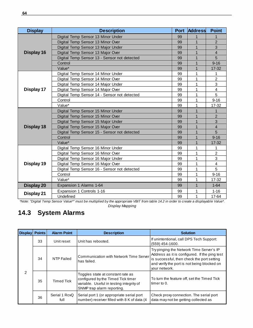
System Alarms14.3
Display Points Alarm Point Description Solution
2
33 Unit reset Unit has rebooted.If unintentional, call DPS Tech Support:(559) 454-1600.
34 NTP FailedCommunication with Network Time Serverhas failed.
Try pinging the Network Time Server’s IPAddress as it is configured. If the ping testis successful, then check the port settingand verify the port is not being blocked onyour network.
35 Timed Tick
Toggles state at constant rate asconfigured by the Timed Tick timervariable. Useful in testing integrity ofSNMP trap alarm reporting.
To turn the feature off, set the Timed Ticktimer to 0.
36Serial 1 RcvQ
fullSerial port 1 (or appropriate serial portnumber) receiver filled with 8 K of data (4
Check proxy connection. The serial portdata may not be getting collected as

65
Display Points Alarm Point Description Solution
K if BAC active) expected.
37Dynamic
memory fullNot expected to occur. Call DPS Tech Support (559) 454-1600
38Notification 1
failedA notification 1 event, such as a page oremail, was unsuccessful.
Use RPT filter debug to help diagnosenotification problems.
39Notification 2
failedA notification 2 event, such as a page oremail, was unsuccessful.
Use RPT filter debug to help diagnosenotification problems.
40Notification 3
failedA notification 3 event, such as a page oremail, was unsuccessful.
Use RPT filter debug to help diagnosenotification problems.
41Notification 4
failedA notification 4 event, such as a page oremail, was unsuccessful.
Use RPT filter debug to help diagnosenotification problems.
42Notification 5
failedA notification 5 event, such as a page oremail, was unsuccessful.
Use RPT filter debug to help diagnosenotification problems.
43Notification 6
failedA notification 6 event, such as a page oremail, was unsuccessful.
Use RPT filter debug to help diagnosenotification problems.
44Notification 7
failedA notification 7 event, such as a page oremail, was unsuccessful.
Use RPT filter debug to help diagnosenotification problems.
45Notification 8
failedA notification 8 event, such as a page oremail, was unsuccessful.
Use RPT filter debug to help diagnosenotification problems.
51
Expansion 1Failed
Expansion shelf 1 communication linkfailure.
Verify the number of configured NGDdxunits.Use EXP filter debug and port LEDs tohelp diagnose the problem. Verify theaddressing on the NGDdx unit.
57Default
Configuration
The internal NVRAM may be damaged.The unit is using default configurationsettings.
Login to the NetGuardian's web browserand configure the unit. Power cycle to see ifthe alarm clears.
58Dip Switch
Config
Reserved for future use to enablebackwards compatibility with theNetGuardian G2.
59MAC Address
Not SetThe MAC Address is not set Call DPS Tech Support - (559) - 454-1600
60IP Address Not
SetThe IP Address is not set
See Section "Quick Start: How to Connect tothe NetGuardian via Craft Port." If not usingthe NetGuardian over LAN, set the IPaddress to 255.255.255.255
61LAN hardware
errorThe unit does not have a solid LAN link tothe hub, switch, or router
If connecting to a hub, you might require aLAN crossover cable
62SNMP
processing errorSNMP trap address is not defined and anSNMP trap event occurred..
Check proxy connection. The serial portdata may not be getting collected asexpected.
63SNMP
community errorCommunity string does not match yourSNMP master's community string.
Verify both community strings to make surethey match.
64LAN TX packet
dropAn error occurred transmitting data overLAN.
Verify that you can ping both devices.
System Alarms
66
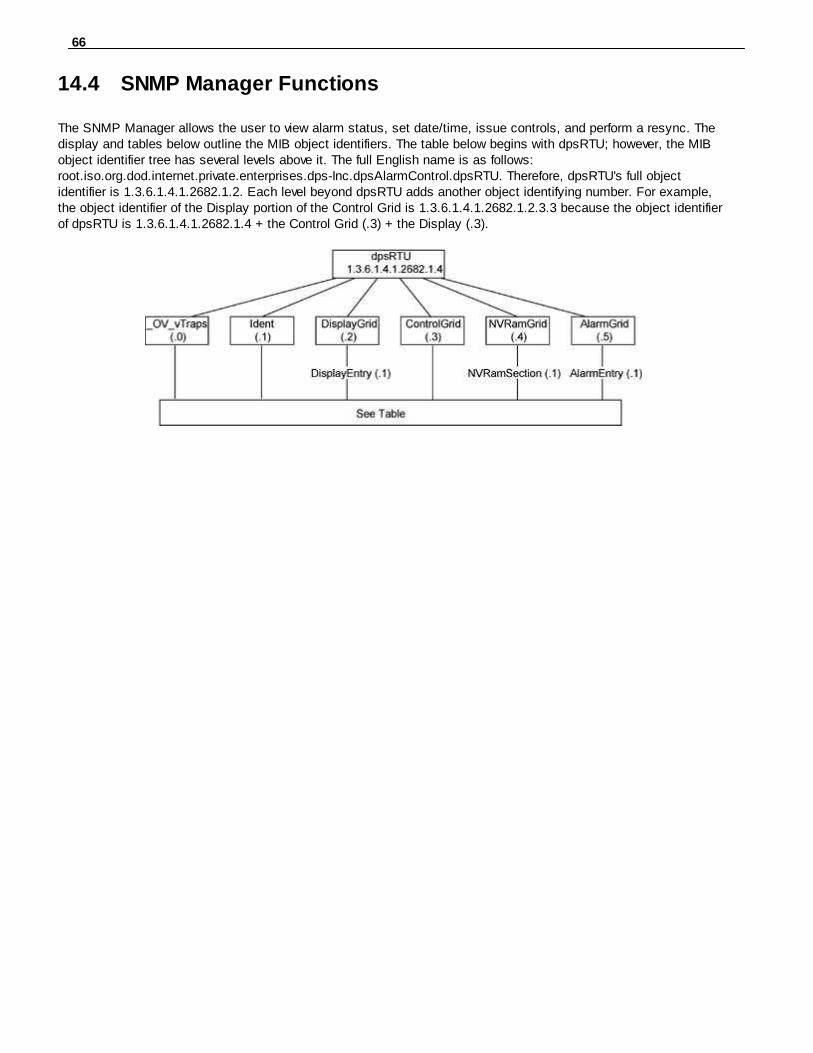
SNMP Manager Functions14.4
The SNMP Manager allows the user to view alarm status, set date/time, issue controls, and perform a resync. Thedisplay and tables below outline the MIB object identifiers. The table below begins with dpsRTU; however, the MIBobject identifier tree has several levels above it. The full English name is as follows: root.iso.org.dod.internet.private.enterprises.dps-Inc.dpsAlarmControl.dpsRTU. Therefore, dpsRTU's full objectidentifier is 1.3.6.1.4.1.2682.1.2. Each level beyond dpsRTU adds another object identifying number. For example,the object identifier of the Display portion of the Control Grid is 1.3.6.1.4.1.2682.1.2.3.3 because the object identifierof dpsRTU is 1.3.6.1.4.1.2682.1.4 + the Control Grid (.3) + the Display (.3).

67
Tbl. B1 (O.)_OV_Trapspoints
_OV_vTraps(1.3.6.1.4.1.2682.1.2.0)
PointSet (.20)
PointClr (.21)
SumPSet (.101)
SumPClr (.102)
ComFailed (.103)
ComRestored (.014)
P0001Set (.10001) throughP0064Set (.10064)
P0001Clr (.20001) throughP0064Clr (.20064)
Tbl. B2 (.1) Identity points
Ident (1.3.6.1.4.1.2682.1.2.1)
Manufacturer (.1)
Model (.2)
Firmware Version (.3)
DateTime (.4)
ResyncReq (.5)*
* Must be set to "1" to perform theresync request which will resend TRAPsfor any standing alarm.
Tbl. B3 (.2) DisplayGridpoints
DisplayEntry(1.3.6.1.4.1.2682.1.2.2.1)
Port (.1)
Address (.2)
Display (.3)
DispDesc (.4)*
PntMap (.5)*
Tbl. B3 (.3) ControlGridpoints
ControlGrid(1.3.6.1.4.1.2682.1.2.3)
Port (.1)
Address (.2)
Display (.3)
Point (.4)
Action (.5)
Tbl. B6 (.6) Analog Channels
Channel Entry(1.3.6.1.4.1.2682.1.4.6.1)
Channel Number (.1)
Enabled (.2)
Description (.3)
Value (.4)
Thresholds (.5)*
*If Mj, Mn is assumed
Tbl. B5 (.5) AlarmEntrypoints
AlarmEntry(1.3.6.4.1.2682.1.2.5.1)
Aport (.1)
AAddress (.2)
ADisplay (.3)
APoint (.4)
APntDesc (.5)*
AState (.6)
* For specific alarm points, seeTable B6

68
SNMP Granular Trap Packets14.5
The tables below provide a list of the information contained in the SNMP Trap packets sent by the NetGuardian.
SNMP Trap managers can use one of two methods to get alarm information: 1. Granular traps (not necessary to define point descriptions for the NetGuardian 480) OR2. The SNMP manager reads the description from the Trap.
UDP Header Description
1238 Source port
162 Destination port
303 Length
0xBAB0 Checksum
UDP Headers and descriptions
SNMP Header Description
0 Version
Public Request
Trap Request
1.3.6.1.4.1.2682.1.4 Enterprise
126.10.230.181 Agent address
Enterprise Specific Generic Trap
8001 Specific Trap
617077 Time stamp
1.3.7.1.2.1.1.1.0 Object
NetGuardian 480 v1.0K Value
1.3.6.1.2.1.1.6.0 Object
1-800-622-3314 Value
1.3.6.1.4.1.2682.1.4.4.1.0 Object
01-02-1995 05:08:27.760 Value
1.3.6.1.4.1.2682.1.4.5.1.1.99.1.1.1 Object
99 Value
1.3.6.1.4.1.2682.1.4.5.1.2.99.1.1.1 Object
1 Value
1.3.6.1.4.1.2682.1.4.5.1.3.99.1.1.1 Object
1 Value
1.3.6.1.4.1.2682.1.4.5.1.4.99.1.1.1 Object
1 Value
1.3.6.1.4.1.2682.1.4.5.1.5.99.1.1.1 Object
Rectifier Failure Value
1.3.6.1.4.1.2682.1.4.5.1.6.99.1.1.1 Object
Alarm Value
SNMP Headers and descriptions

69
Frequently Asked Questions15
Here are answers to some common questions from NetGuardian users. The latest FAQs can be found on theNetGuardian support web page, http://www.dpstele.com.
If you have a question about the NetGuardian, please call us at (559) 454-1600 or e-mail us [email protected].
General FAQs15.1
Q. How do I telnet to the NetGuardian?A. You must use Port 2002 to connect to the NetGuardian. Configure your Telnet client to connect using TCP/IP
(not "Telnet," or any other port options). For connection information, enter the IP address of the NetGuardianand Port 2002. For example, to connect to the NetGuardian using the standard Windows Telnet client, clickStart, click Run, and type "telnet <NetGuardian IP address> 2002."
Q. How do I connect my NetGuardian to the LAN?A. To connect your NetGuardian to your LAN, you need to configure the unit IP address, the subnet mask and the
default gateway. A sample configuration could look like this:Unit Address: 192.168.1.100subnet mask: 255.255.255.0Default Gateway: 192.168.1.1Save your changes by writing to NVRAM and reboot. Any change to the unit's IP configuration requires a reboot.
Q. When I connect to the NetGuardian through the craft port on the front panel it either doesn't work rightor it doesn't work at all. What's going on?
A. Make sure your using the right COM port settings. Your COM port settings should read:Bits per second: 9600 (9600 baud)Data bits: 8Parity: NoneStop bits: 1Flow control: NoneImportant! Flow control must be set to none. Flow control normally defaults to hardware in most terminalprograms, and this will not work correctly with the NetGuardian.
Q. The LAN link LED is green on my NetGuardian, but I can't poll it from my T/Mon.A. Some routers will not forward packets to an IP address until the MAC address of the destination device has
been registered on the router's Address Resolution Protocol (ARP) table. Enter the IP address of your gatewayand your T/Mon system to the ARP table.
70
Technical Support16
DPS Telecom products are backed by our courteous, friendly Technical Support representatives, who will give youthe best in fast and accurate customer service. To help us help you better, please take the following steps beforecalling Technical Support:
1. Check the DPS Telecom website.You will find answers to many common questions on the DPS Telecom website, at http://www.dpstele.com/support/. Look here first for a fast solution to your problem.
2. Prepare relevant information.
Having important information about your DPS Telecom product in hand when you call will greatly reduce the time ittakes to answer your questions. If you do not have all of the information when you call, our Technical Supportrepresentatives can assist you in gathering it. Please write the information down for easy access. Please haveyour user manual and hardware serial number ready.
3. Have access to troubled equipment.Please be at or near your equipment when you call DPS Telecom Technical Support. This will help us solve yourproblem more efficiently.
4. Call during Customer Support hours.Customer support hours are Monday through Friday, from 7 A.M. to 6 P.M., Pacific time. The DPS TelecomTechnical Support phone number is (559) 454-1600.
Emergency Assistance: Emergency assistance is available 24 hours a day, 7 days a week. For emergencyassistance after hours, allow the phone to ring until it is answered with a paging message. You will be asked to enteryour phone number. An on-call technical support representative will return your call as soon as possible.

71

72
End User License Agreement17
All Software and firmware used in, for, or in connection with the Product, parts, subsystems, or derivatives thereof, inwhatever form, including, without limitation, source code, object code and microcode, including any computerprograms and any documentation relating to or describing such Software is furnished to the End User only under anon-exclusive perpetual license solely for End User's use with the Product.
The Software may not be copied or modified, in whole or in part, for any purpose whatsoever. The Software may notbe reverse engineered, compiled, or disassembled. No title to or ownership of the Software or any of its parts istransferred to the End User. Title to all patents, copyrights, trade secrets, and any other applicable rights shallremain with the DPS Telecom.
DPS Telecom's warranty and limitation on its liability for the Software is as described in the warranty informationprovided to End User in the Product Manual.
End User shall indemnify DPS Telecom and hold it harmless for and against any and all claims, damages, losses,costs, expenses, obligations, liabilities, fees and costs and all amounts paid in settlement of any claim, action orsuit which may be asserted against DPS Telecom which arise out of or are related to the non-fulfillment of anycovenant or obligation of End User in connection with this Agreement.
This Agreement shall be construed and enforced in accordance with the laws of the State of California, withoutregard to choice of law principles and excluding the provisions of the UN Convention on Contracts for theInternational Sale of Goods. Any dispute arising out of the Agreement shall be commenced and maintained only inFresno County, California. In the event suit is brought or an attorney is retained by any party to this Agreement toseek interpretation or construction of any term or provision of this Agreement, to enforce the terms of thisAgreement, to collect any money due, or to obtain any money damages or equitable relief for breach, the prevailingparty shall be entitled to recover, in addition to any other available remedy, reimbursement for reasonable attorneys'fees, court costs, costs of investigation, and other related expenses.

73


WarrantyDPS Telecom warrants, to the original purchaser only, that its products a) substantially conform to DPS' publishedspecifications and b) are substantially free from defects in material and workmanship. This warranty expires two years from thedate of product delivery with respect to hardware and ninety days from the date of product delivery with respect to software.If the purchaser discovers within these periods a failure of the product to substantially conform to the specifications or thatthe product is not substantially free from defects in material and workmanship, the purchaser must promply notify DPS. Withinreasonable time after notification, DPS will endeavor to correct any substantial non-conformance with the specifications orsubstantial defects in material and workmanship, with new or used replacement parts. All warranty service will be performed atthe company's office in Fresno, California, at no charge to the purchaser, other than the cost of shipping to and from DPS,which shall be the responsiblity of the purchaser. If DPS is unable to repair the product to conform to the warranty, DPS willprovide at its option one of the following: a replacement product or a refund of the purchase price for the non-conformingproduct. These remedies are the purchaser's only remedies for breach of warranty. Prior to initial use the purchaser shall havedetermined the suitability of the product for its intended use. DPS does not warrant a) any product, components or parts notmanufactured by DPS, b) defects caused by the purchaser's failure to provide a suitable installation environment for theproduct, c) damage caused by use of the product for purposes other than those for which it was designed, d) damage causedby disasters such as fire, flood, wind or lightning unless and to the extent that the product specification provides forresistance to a defined disaster, e) damage caused by unauthorized attachments or modifications, f) damage during shipmentfrom the purchaser to DPS, or g) any abuse or misuse by the purchaser.
THE FOREGOING WARRANTIES ARE IN LIEU OF ALL OTHER WARRANTIES, EXPRESS OR IMPLIED, INCLUDING BUTNOT LIMITED TO THE IMPLIED WARRANTIES OF MERCHANTABILITY AND FITNESS FOR A PARTICULARPURPOSE.
In no event will DPS be liable for any special, incidental, or consequential damages based on breach of warranty, breach ofcontract, negligence, strict tort, or any other legal theory. Damages that DPS will not be responsible for include but are notlimited to, loss of profits; loss of savings or revenue; loss of use of the product or any associated equipment; cost of capital;cost of any substitute equipment, facilities or services; downtime; claims of third parties including customers; and injury toproperty.
The purchaser shall fill out the requested information on the Product Warranty Card and mail the card to DPS. This cardprovides information that helps DPS make product improvements and develop new products.
For an additional fee DPS may, at its option, make available by written agreement only an extended warranty providing anadditional period of time for the applicability of the standard warranty.
Technical SupportIf a purchaser believes that a product is not operating in substantial conformance with DPS' published specifications or thereappear to be defects in material and workmanship, the purchaser should contact our technical support representatives. If theproblem cannot be corrected over the telephone and the product and problem are covered by the warranty, the technicalsupport representative will authorize the return of the product for service and provide shipping information. If the product isout of warranty, repair charges will be quoted. All non-warranty repairs receive a 90-day warranty.

(800) 622-3314 • www.dpstele.com • 4955 E. Yale Avenue, Fresno, California 93727
Free Tech Support is Only a Click Away
Free Tech Support in Your Email: The Protocol Alarm Monitoring Ezine
The Protocol Alarm Monitoring Ezine is your free emailtech support alert, delivered directly to your in-boxevery two weeks. Every issue has news you can useright away:
Free Tech Support on the Web: MyDPS
MyDPS is your personalized, members-only online resource.Registering for MyDPS is fast, free, and gives you exclusiveaccess to:
• Firmware and software downloads and upgrades• Product manuals• Product datasheets• Exclusive user forms
Expert tips on using your alarm monitoringequipment — advanced techniques that will saveyou hours of work
Educational White Papers deliver fast informaltutorials on SNMP, ASCII processing, TL1 andother alarm monitoring technologies
New product and upgrade announcements keepyou up to date with the latest technology
Exclusive access to special offers for DPSTelecom Factory Training, product upgrade offersand discounts
To get your free subscription to The Protocol register online at
•
•
•
•
Need help with your alarm monitoring? DPS Information Services are ready toserve you … in your email or over the Web!
www.DpsTelecom.com
www.TheProtocol.com/register
www.DpsTelecom.com/register
Register for MyDPS online at
Top Related