


Languages
Pages
Legal


NEO-M9Nu-blox M9 standard precision module
Data sheet
AbstractTechnical data sheet describing the u-blox NEO-M9N module. NEO-M9N offers ultra-robust meter-level GNSS positioning performance withconcurrent reception of up to four GNSS (GPS, GLONASS, BeiDou, Galileo)in a 12.2 x 16.0 mm package.
www.u-blox.com
UBX-19014285 - R03
NEO-M9N - Data sheet
Document informationTitle NEO-M9N
Subtitle u-blox M9 standard precision module
Document type Data sheet
Document number UBX-19014285
Revision and date R03 24-Jan-2020
Document status Advance information
Product status Corresponding content status
In development /prototype
Objective specification Target values. Revised and supplementary data will be published later.
Engineering sample Advance information Data based on early testing. Revised and supplementary data will bepublished later.
Initial production Early production information Data from product verification. Revised and supplementary data may bepublished later.
Mass production /End of life
Production information Document contains the final product specification.
This document applies to the following products:
Product name Type number Firmware version PCN reference
NEO-M9N NEO-M9N-00B-00 SPG 4.00 N/A
u-blox reserves all rights to this document and the information contained herein. Products, names, logos and designsdescribed herein may in whole or in part be subject to intellectual property rights. Reproduction, use, modification ordisclosure to third parties of this document or any part thereof without the express permission of u-blox is strictly prohibited.
The information contained herein is provided "as is" and u-blox assumes no liability for the use of the information. No warranty,either express or implied, is given with respect to, including but not limited to, the accuracy, correctness, reliability and fitnessfor a particular purpose of the information. This document may be revised by u-blox at any time. For most recent documents,please visit www.u blox.com.
Copyright © 2020, u-blox AG.
u-blox is a registered trademark of u-blox Holding AG in the EU and other countries.
UBX-19014285 - R03
Page 2 of 21Advance information

NEO-M9N - Data sheet
Contents
1 Functional description......................................................................................................... 41.1 Overview.................................................................................................................................................... 41.2 Performance............................................................................................................................................. 41.3 Supported GNSS constellations.......................................................................................................... 51.4 Supported protocols............................................................................................................................... 61.5 Firmware features...................................................................................................................................6
2 System description...............................................................................................................72.1 Block diagram.......................................................................................................................................... 7
3 Pin definition........................................................................................................................... 83.1 Pin assigment.......................................................................................................................................... 8
4 Electrical specification...................................................................................................... 104.1 Absolute maximum ratings................................................................................................................ 104.2 Operating conditions............................................................................................................................104.3 Indicative power requirements...........................................................................................................11
5 Communications interfaces.............................................................................................125.1 UART interface...................................................................................................................................... 125.2 SPI interface...........................................................................................................................................125.3 Slave I2C interface................................................................................................................................135.4 USB interface.........................................................................................................................................155.5 Default interface settings...................................................................................................................15
6 Mechanical specification.................................................................................................. 16
7 Reliability tests and approvals....................................................................................... 177.1 Approvals................................................................................................................................................ 17
8 Labeling and ordering information................................................................................ 188.1 Product labeling.................................................................................................................................... 188.2 Explanation of product codes............................................................................................................ 188.3 Ordering codes...................................................................................................................................... 18
Related documents................................................................................................................ 19
Revision history....................................................................................................................... 20
UBX-19014285 - R03
Contents Page 3 of 21Advance information

NEO-M9N - Data sheet
1 Functional description
1.1 OverviewThe NEO-M9N GNSS receiver features the u-blox M9 standard precision GNSS platform, andprovides exceptional sensitivity and acquisition times for all L1 GNSS systems. u-blox M9 receiversare available in different variants to serve automotive and industrial tracking applications, such asnavigation, telematics and UAVs.
The u-blox M9 standard precision GNSS platform, which delivers meter-level accuracy, succeeds thewell-known u-blox M8 product range.
u-blox M9 receivers support concurrent reception of four GNSS. The high number of visible satellitesallows the receiver to select the best signals. This maximizes the position accuracy, in particularunder challenging conditions such as deep urban canyons.
u-blox M9 receivers detect jamming and spoofing events and report them to the host, which allowsthe system to react to such events. Advanced filtering algorithms mitigate the impact of RFinterference and jamming, thus enabling the product to operate as intended.
The receiver also provides higher navigation rate and improved security features compared toprevious u-blox GNSS generations.
The NEO-M9N module is available in the 12.2 x 16.0 mm NEO form factor LCC package.
1.2 PerformanceParameter Specification
Receiver type Multi-constellation GNSS standard precision receiver
Accuracy of time pulse signal RMS99%
30ns60ns
Frequency of time pulse signal 0.25 Hz to 10 MHz(configurable)
Operational limits1 Dynamics
Altitude
Velocity
≤ 4 g
80,000 m500 m/s
Velocity accuracy2 0.05 m/s
Dynamic heading accuracy 0.3 deg
GNSS GPS+GLO+GAL+BDS GPS+GLO+GAL GPS+GLO GPS+BDS GPS+GAL
Acquisition3 Cold start
Hot start
Aided start4
24 s
2 s
2 s
25 s
2 s
2 s
26 s
2 s
2 s
28 s
2 s
2 s
29 s
2 s
2 s
Nav. update rate PVT 25 Hz 25 Hz 25 Hz 25 Hz 25 Hz
1 Assuming Airborne 4 g platform2 50% @ 30 m/s for dynamic operation3 Commanded starts. All satellites at -130 dBm. GPS always in combination with QZSS and SBAS. Measured at room
temperature.4 Dependent on the speed and latency of the aiding data connection, commanded starts.
UBX-19014285 - R03
1 Functional description Page 4 of 21Advance information
NEO-M9N - Data sheet
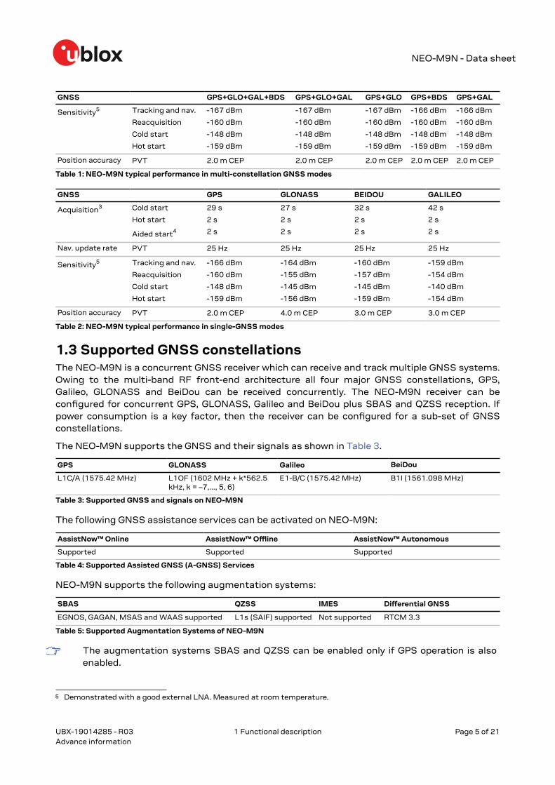
GNSS GPS+GLO+GAL+BDS GPS+GLO+GAL GPS+GLO GPS+BDS GPS+GAL
Sensitivity5 Tracking and nav.
Reacquisition
Cold start
Hot start
-167 dBm
-160 dBm
-148 dBm
-159 dBm
-167 dBm
-160 dBm
-148 dBm
-159 dBm
-167 dBm
-160 dBm
-148 dBm
-159 dBm
-166 dBm
-160 dBm
-148 dBm
-159 dBm
-166 dBm
-160 dBm
-148 dBm
-159 dBm
Position accuracy PVT 2.0 m CEP 2.0 m CEP 2.0 m CEP 2.0 m CEP 2.0 m CEP
Table 1: NEO-M9N typical performance in multi-constellation GNSS modes
GNSS GPS GLONASS BEIDOU GALILEO
Acquisition3 Cold start
Hot start
Aided start4
29 s
2 s
2 s
27 s
2 s
2 s
32 s
2 s
2 s
42 s
2 s
2 s
Nav. update rate PVT 25 Hz 25 Hz 25 Hz 25 Hz
Sensitivity5 Tracking and nav.
Reacquisition
Cold start
Hot start
-166 dBm
-160 dBm
-148 dBm
-159 dBm
-164 dBm
-155 dBm
-145 dBm
-156 dBm
-160 dBm
-157 dBm
-145 dBm
-159 dBm
-159 dBm
-154 dBm
-140 dBm
-154 dBm
Position accuracy PVT 2.0 m CEP 4.0 m CEP 3.0 m CEP 3.0 m CEP
Table 2: NEO-M9N typical performance in single-GNSS modes
1.3 Supported GNSS constellationsThe NEO-M9N is a concurrent GNSS receiver which can receive and track multiple GNSS systems.Owing to the multi-band RF front-end architecture all four major GNSS constellations, GPS,Galileo, GLONASS and BeiDou can be received concurrently. The NEO-M9N receiver can beconfigured for concurrent GPS, GLONASS, Galileo and BeiDou plus SBAS and QZSS reception. Ifpower consumption is a key factor, then the receiver can be configured for a sub-set of GNSSconstellations.
The NEO-M9N supports the GNSS and their signals as shown in Table 3.
GPS GLONASS Galileo BeiDou
L1C/A (1575.42 MHz) L1OF (1602 MHz + k*562.5kHz, k = –7,..., 5, 6)
E1-B/C (1575.42 MHz) B1I (1561.098 MHz)
Table 3: Supported GNSS and signals on NEO-M9N
The following GNSS assistance services can be activated on NEO-M9N:
AssistNow™ Online AssistNow™ Offline AssistNow™ Autonomous
Supported Supported Supported
Table 4: Supported Assisted GNSS (A-GNSS) Services
NEO-M9N supports the following augmentation systems:
SBAS QZSS IMES Differential GNSS
EGNOS, GAGAN, MSAS and WAAS supported L1s (SAIF) supported Not supported RTCM 3.3
Table 5: Supported Augmentation Systems of NEO-M9N
The augmentation systems SBAS and QZSS can be enabled only if GPS operation is alsoenabled.
5 Demonstrated with a good external LNA. Measured at room temperature.
UBX-19014285 - R03
1 Functional description Page 5 of 21Advance information

NEO-M9N - Data sheet
1.4 Supported protocolsThe NEO-M9N supports the following protocols:
Protocol Type
UBX Input/output, binary, u-blox proprietary
NMEA 4.10 Input/output, ASCII
RTCM 3.3 Input only, binary
Table 6: Supported protocols
For specification of the protocols, see the u-blox NEO-M9N Interface description [2].
1.5 Firmware featuresFeature Description
Assisted GNSS AssistNow Online, AssistNow Offline and AssistNow Autonomous supported
Backup modes Hardware backup mode, software backup mode
Data batching Autonomous tracking up to 5 min
Data-logger Position, velocity, time, and odometer data
Geo-fencing Up to 4 circular areas
Power save modes On/off, cyclic
Odometer Measure traveled distance with support for different user profiles
Upgradeable firmware Firmware can be upgraded via host upload or updated in the internal flash memory.
Table 7: Firmware features
Feature Description
Anti-jamming RF interference and jamming detection and reporting; Active GNSS in-band filtering
Anti-spoofing Spoofing detection and reporting
Configuration lockdown Receiver configuration can be locked by command
Message integrity All messages signed with SHA-256
Secure boot Only signed FW images executed
Table 8: Security features
UBX-19014285 - R03
1 Functional description Page 6 of 21Advance information

NEO-M9N - Data sheet
2 System description
2.1 Block diagram
Figure 1: NEO-M9N block diagram
UBX-19014285 - R03
2 System description Page 7 of 21Advance information
NEO-M9N - Data sheet
3 Pin definition
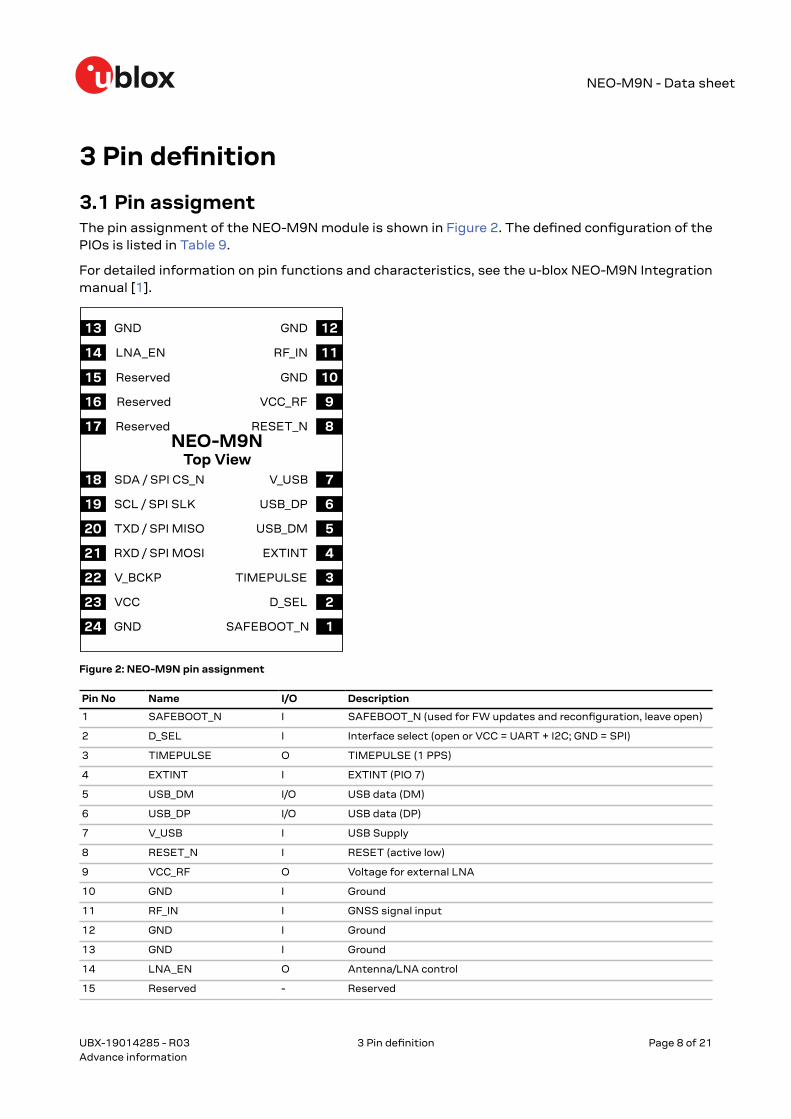
3.1 Pin assigmentThe pin assignment of the NEO-M9N module is shown in Figure 2. The defined configuration of thePIOs is listed in Table 9.
For detailed information on pin functions and characteristics, see the u-blox NEO-M9N Integrationmanual [1].
Figure 2: NEO-M9N pin assignment
Pin No Name I/O Description
1 SAFEBOOT_N I SAFEBOOT_N (used for FW updates and reconfiguration, leave open)
2 D_SEL I Interface select (open or VCC = UART + I2C; GND = SPI)
3 TIMEPULSE O TIMEPULSE (1 PPS)
4 EXTINT I EXTINT (PIO 7)
5 USB_DM I/O USB data (DM)
6 USB_DP I/O USB data (DP)
7 V_USB I USB Supply
8 RESET_N I RESET (active low)
9 VCC_RF O Voltage for external LNA
10 GND I Ground
11 RF_IN I GNSS signal input
12 GND I Ground
13 GND I Ground
14 LNA_EN O Antenna/LNA control
15 Reserved - Reserved
UBX-19014285 - R03
3 Pin definition Page 8 of 21Advance information

NEO-M9N - Data sheet
Pin No Name I/O Description
16 Reserved - Reserved
17 Reserved - Reserved
18 SDA / SPI CS_N I/O I2C data if D_SEL = VCC (or open); SPI chip select if D_SEL = GND
19 SCL / SPI SLK I/O I2C clock if D_SEL = VCC (or open); SPI clock if D_SEL = GND
20 TXD / SPI MISO O UART output if D_SEL = VCC (or open); SPI MISO if D_SEL = GND
21 RXD / SPI MOSI I UART input if D_SEL = VCC (or open); SPI MOSI if D_SEL = GND
22 V_BCKP I Backup voltage supply
23 VCC I Supply voltage
24 GND I Ground
Table 9: NEO-M9N pin assigment
For detailed information on the pin functions and characteristics see the u-blox NEO-M9NIntegration manual [1].
UBX-19014285 - R03
3 Pin definition Page 9 of 21Advance information

NEO-M9N - Data sheet
4 Electrical specificationThe limiting values given are in accordance with the Absolute Maximum Rating System(IEC 134). Stress above one or more of the limiting values may cause permanent damageto the device. These are stress ratings only. Operation of the device at these or at any otherconditions above those given below is not implied. Exposure to limiting values for extendedperiods may affect device reliability.
Where application information is given, it is advisory only and does not form part of thespecification.
For detailed information on the device integration, see the u-blox NEO-M9N Integrationmanual [1].
4.1 Absolute maximum ratingsParameter Symbol Condition Min Max Units
Power supply voltage VCC -0.5 3.6 V
Backup battery voltage V_BCKP -0.5 3.6 V
Input pin voltage Vin VCC ≤ 3.1 V -0.5 VCC + 0.5 V
VCC > 3.1 V -0.5 3.6 V
VCC_RF output current ICC_RF 100 mA
Supply voltage USB V_USB –0.5 3.6 V
USB signals USB_DN,USB_DP
-0.5 V_USB + 0.5 V
Input power at RF_IN Prfin source impedance =50 Ω, continuous wave
136 dBm
Storage temperature Tstg -40 +85 °C
Table 10: Absolute maximum ratings
The product is not protected against overvoltage or reversed voltages. Voltage spikesexceeding the power supply voltage specification, given in the table above, must be limitedto values within the specified boundaries by using appropriate protection diodes.
4.2 Operating conditionsAll specifications are at an ambient temperature of 25 °C. Extreme operating temperaturescan significantly impact the specification values. Applications operating near thetemperature limits should be tested to ensure the specification.
Parameter Symbol Min Typical Max Units Condition
Power supply voltage VCC 2.7 3.0 3.6 V
Backup battery voltage V_BCKP 1.65 3.6 V
Backup battery current I_BCKP 36 µA
SW backup current I_SWBCKP 0.33 mA
Input pin voltage range Vin 0 VCC V
Digital IO pin low level input voltage Vil 0.4 V
Digital IO pin high level input voltage Vih 0.8 * VCC V
Digital IO pin low level output voltage Vol 0.4 V Iol = 2 mA
Digital IO pin high level output voltage Voh VCC – 0.4 V Ioh = 2 mA
6 +13 dBm for outband; 0 dBm for inband
UBX-19014285 - R03
4 Electrical specification Page 10 of 21Advance information
NEO-M9N - Data sheet
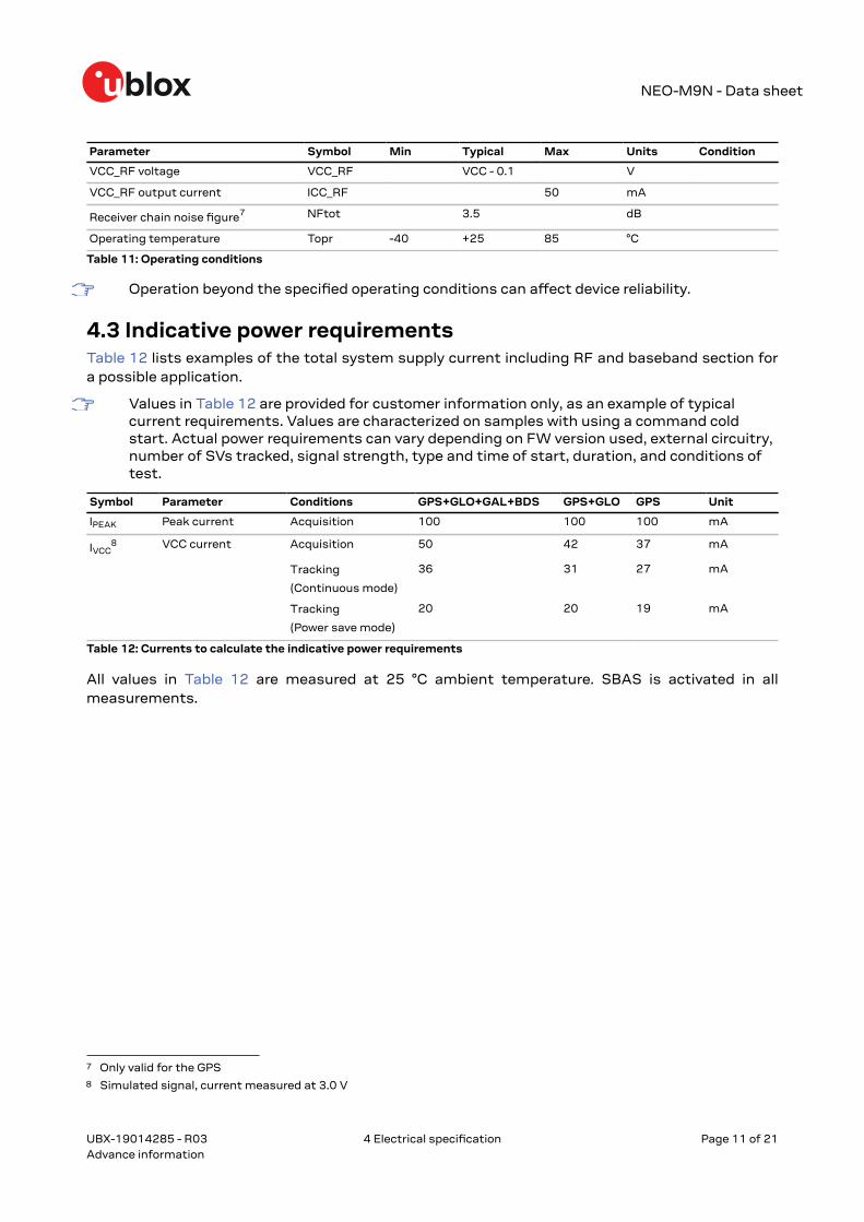
Parameter Symbol Min Typical Max Units Condition
VCC_RF voltage VCC_RF VCC - 0.1 V
VCC_RF output current ICC_RF 50 mA
Receiver chain noise figure7 NFtot 3.5 dB
Operating temperature Topr -40 +25 85 °C
Table 11: Operating conditions
Operation beyond the specified operating conditions can affect device reliability.
4.3 Indicative power requirementsTable 12 lists examples of the total system supply current including RF and baseband section fora possible application.
Values in Table 12 are provided for customer information only, as an example of typicalcurrent requirements. Values are characterized on samples with using a command coldstart. Actual power requirements can vary depending on FW version used, external circuitry,number of SVs tracked, signal strength, type and time of start, duration, and conditions oftest.
Symbol Parameter Conditions GPS+GLO+GAL+BDS GPS+GLO GPS Unit
IPEAK Peak current Acquisition 100 100 100 mA
IVCC8 VCC current Acquisition 50 42 37 mA
Tracking
(Continuous mode)
36 31 27 mA
Tracking
(Power save mode)
20 20 19 mA
Table 12: Currents to calculate the indicative power requirements
All values in Table 12 are measured at 25 °C ambient temperature. SBAS is activated in allmeasurements.
7 Only valid for the GPS8 Simulated signal, current measured at 3.0 V
UBX-19014285 - R03
4 Electrical specification Page 11 of 21Advance information

NEO-M9N - Data sheet
5 Communications interfacesThere are several communications interfaces including UART, SPI, I2C9 and USB.
All the inputs have internal pull-up resistors in normal operation and can be left open if not used.All the PIOs are supplied by VCC, therefore all the voltage levels of the PIO pins are related to VCCsupply voltage.
5.1 UART interfaceThere is one UART interface: UART1, which operates up to and including a speed of 921600 baud.No hardware flow control is supported.
UART1 is enabled by default if D_SEL = 1 or unconnected.
Figure 3: NEO-M9N module UART timing specifications
Symbol Parameter Min Max Unit
tECH High period of external data input 0 0.4 µs
tECL Low period of external data input TBA TBA µs
Ru Baudrate 4800 921600 bd
tCR Rise time of data 5 ns
tCF Fall time of data 5 ns
Table 13: NEO-M9N UART timings and specifications
5.2 SPI interfaceThe NEO-M9N has an SPI slave interface that can be selected by setting D_SEL = 0. The SPI pinsavailable are: SPI_MISO (TXD), SPI_MOSI (RXD), SPI_CS_N, SPI_CLK. The SPI interface is designedto allow communication to a host CPU. The interface can be operated in slave mode only. Note thatSPI is not available in the default configuration because its pins are shared with the UART and I2Cinterfaces. The maximum transfer rate using SPI is 125 kB/s and the maximum SPI clock frequencyis 5.5 MHz.
This section provides SPI timing values for the NEO-M9N slave operation. The following tablespresent timing values under different capacitive loading conditions. Default SPI configuration isCPOL = 0 and CPHA = 0.
9 I2C is a registered trademark of Philips/NXP
UBX-19014285 - R03
5 Communicationsinterfaces
Page 12 of 21Advance information
NEO-M9N - Data sheet
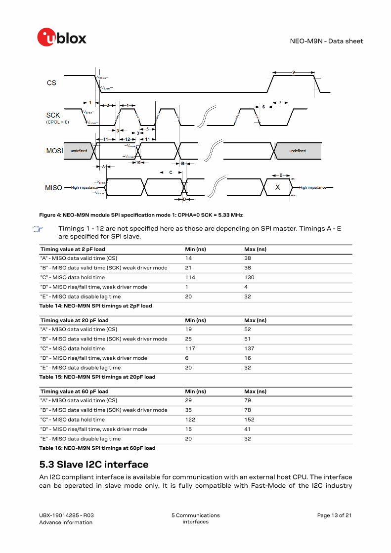
Figure 4: NEO-M9N module SPI specification mode 1: CPHA=0 SCK = 5.33 MHz
Timings 1 - 12 are not specified here as those are depending on SPI master. Timings A - Eare specified for SPI slave.
Timing value at 2 pF load Min (ns) Max (ns)
"A" - MISO data valid time (CS) 14 38
"B" - MISO data valid time (SCK) weak driver mode 21 38
"C" - MISO data hold time 114 130
"D" - MISO rise/fall time, weak driver mode 1 4
"E" - MISO data disable lag time 20 32
Table 14: NEO-M9N SPI timings at 2pF load
Timing value at 20 pF load Min (ns) Max (ns)
"A" - MISO data valid time (CS) 19 52
"B" - MISO data valid time (SCK) weak driver mode 25 51
"C" - MISO data hold time 117 137
"D" - MISO rise/fall time, weak driver mode 6 16
"E" - MISO data disable lag time 20 32
Table 15: NEO-M9N SPI timings at 20pF load
Timing value at 60 pF load Min (ns) Max (ns)
"A" - MISO data valid time (CS) 29 79
"B" - MISO data valid time (SCK) weak driver mode 35 78
"C" - MISO data hold time 122 152
"D" - MISO rise/fall time, weak driver mode 15 41
"E" - MISO data disable lag time 20 32
Table 16: NEO-M9N SPI timings at 60pF load
5.3 Slave I2C interfaceAn I2C compliant interface is available for communication with an external host CPU. The interfacecan be operated in slave mode only. It is fully compatible with Fast-Mode of the I2C industry
UBX-19014285 - R03
5 Communicationsinterfaces
Page 13 of 21Advance information

NEO-M9N - Data sheet
standard. Since the maximum SCL clock frequency is 400 kHz, the maximum bit rate is 400 kbit/s. The interface stretches the clock when slowed down while serving interrupts, therefore the realbit rates may be slightly lower.
The I2C interface is only available with the UART default mode. If the SPI interface isselected by using D_SEL = 0, the I2C interface is not available.
Figure 5: NEO-M9N module I2C slave specification
Symbol Parameter Min (Standard /Fast-mode)
Max Unit
fSCL SCL clock frequency 0 400 kHz
tHD;STA Hold time (repeated) START condition 4.0/1 - µs
tLOW Low period of the SCL clock 5/2 - µs
tHIGH High period of the SCL clock 4.0/1 - µs
tSU;STA Set-up time for a repeated START condition 5/1 - µs
tHD;DAT Data hold time 0/0 - µs
tSU;DAT Data set-up time 250/100 ns
tr Rise time of both SDA and SCL signals - 1000/300 (for C = 400pF) ns
tf Fall time of both SDA and SCL signals - 300/300 (for C = 400pF) ns
tSU;STO Set-up time for STOP condition 4.0/1 - µs
tBUF Bus free time between a STOP and STARTcondition
5/2 - µs
tVD;DAT Data valid time - 4/1 µs
tVD;ACK Data valid acknowledge time - 4/1 µs
VnL Noise margin at the low level 0.1 VCC - V
VnH Noise margin at the high level 0.2 VCC - V
Table 17: NEO-M9N I2C slave timings and specifications
UBX-19014285 - R03
5 Communicationsinterfaces
Page 14 of 21Advance information

NEO-M9N - Data sheet
5.4 USB interfaceA USB interface, which is compatible to USB version 2.0 FS (Full Speed, 12 Mbit/s), can be used forcommunication to a host. The V_USB pin supplies the USB interface.
5.5 Default interface settingsInterface Settings
UART 38400 Baud, 8 bits, no parity bit, 1 stop bit.
Output messages: NMEA GGA, GLL, GSA, GSV, RMC, VTG, TXT (no UBX).
Input protocols: UBX, NMEA and RTCM 3.3.
USB Output messages activated as in UART. Input protocols available as in UART.
I2C Output messages activated as in UART. Input protocols available as in UART.
SPI Output messages activated as in UART. Input protocols available as in UART.
Table 18: Default interface settings
Refer to the u-blox NEO-M9N Interface description [2] for information about furthersettings.
By default the NEO-M9N outputs NMEA 4.10 messages that include satellite data for all GNSSbands being received. This results in a higher-than-before NMEA load output for each navigationperiod. Make sure the UART baud rate being used is sufficient for the selected navigation rate andthe number of GNSS signals being received.
UBX-19014285 - R03
5 Communicationsinterfaces
Page 15 of 21Advance information

NEO-M9N - Data sheet
6 Mechanical specification
Figure 6: NEO-M9N mechanical drawing
UBX-19014285 - R03
6 Mechanical specification Page 16 of 21Advance information
NEO-M9N - Data sheet
7 Reliability tests and approvalsAll u-blox modules are based on AEC-Q100 qualified GNSS chips.
Tests for product family qualifications are according to ISO 16750 "Road vehicles – environmentalconditions and testing for electrical and electronic equipment”, and appropriate standards.
7.1 ApprovalsThe NEO-M9N is designed to in compliance with the essential requirements and other relevantprovisions of Radio Equipment Directive (RED) 2014/53/EU.
The NEO-M9N complies with the Directive 2011/65/EU (EU RoHS 2) and its amendment Directive(EU) 2015/863 (EU RoHS 3).
Declaration of Conformity (DoC) is available on the u-blox website.
UBX-19014285 - R03
7 Reliability testsand approvals
Page 17 of 21Advance information

NEO-M9N - Data sheet
8 Labeling and ordering informationThis section provides information about product labeling and ordering. For information aboutproduct handling and soldering see the NEO-M9N Integration manual [1].
8.1 Product labelingThe labeling of the NEO-M9N modules provides product information and revision information. Formore information contact u-blox sales.
8.2 Explanation of product codesThree different product code formats are used. The Product name is used in documentation suchas this data sheet and identifies all u-blox products, independent of packaging and quality grade.The Ordering code includes options and quality, while the Type number includes the hardware andfirmware versions. Table 19 below details these three different formats.
Format Structure Code for this product
Product name PPP-TGV NEO-M9N
Ordering code PPP-TGV-NNQ NEO-M9N-00B
Type number PPP-TGV-NNQ-XX NEO-M9N-00B-00
Table 19: Product code formats
The parts of the product code are explained in Table 20.
Code Meaning Example
PPP Product family NEO
TG Platform M9 = u-blox M9
V Variant N = Standard precision with SAW and LNA
NNQ Option / Quality grade NN: Option [00...99]Q: Grade, A = Automotive, B = Professional
XX Product detail Describes hardware and firmware versions
Table 20: Part identification code
8.3 Ordering codesOrdering code Product Remark
NEO-M9N-00B u-blox NEO-M9N module, professional grade
Table 21: Product ordering codes
Product changes affecting form, fit or function are documented by u-blox. For a list ofProduct Change Notifications (PCNs) see our website at: https://www.u-blox.com/en/product-resources.
UBX-19014285 - R03
8 Labeling andordering information
Page 18 of 21Advance information

NEO-M9N - Data sheet
Related documents[1] NEO-M9N Integration manual, doc. no. UBX-19014286[2] NEO-M9N Interface description, doc. no. UBX-19035940
For regular updates to u-blox documentation and to receive product change notificationsplease register on our homepage (http://www.u-blox.com).
UBX-19014285 - R03
Related documents Page 19 of 21Advance information

NEO-M9N - Data sheet
Revision historyRevision Date Name Status / comments
R01 15-Aug-2019 jesk Objective specification
R02 14-Nov-2019 jesk Advance information
R03 24-Jan-2020 jesk Advance information.Added outband value for Prfin, renamed VDD_USB to V_USB.
UBX-19014285 - R03
Revision history Page 20 of 21Advance information

NEO-M9N - Data sheet
ContactFor complete contact information visit us at www.u-blox.com.
u-blox Offices
North, Central and South America Headquarters Asia, Australia, Pacific
Europe, Middle East, Africa
u-blox America, Inc. u-blox AG u-blox Singapore Pte. Ltd.Phone: +1 703 483 3180 Phone: +41 44 722 74 44 Phone: +65 6734 3811E-mail: [email protected] E-mail: [email protected] E-mail: [email protected] Support: [email protected] Support: [email protected]
Regional Office West Coast Regional Office AustraliaPhone: +1 408 573 3640 Phone: +61 2 8448 2016E-mail: [email protected] E-mail: [email protected] Support: [email protected]
Technical Support Regional Office China (Beijing)Phone: +1 703 483 3185 Phone: +86 10 68 133 545E-mail: [email protected] E-mail: [email protected] Support: [email protected]
Regional Office China (Chongqing) Phone: +86 23 6815 1588 E-mail: [email protected] Support: [email protected]
Regional Office China (Shanghai) Phone: +86 21 6090 4832 E-mail: [email protected] Support: [email protected]
Regional Office China (Shenzhen) Phone: +86 755 8627 1083 E-mail: [email protected] Support: [email protected]
Regional Office India Phone: +91 80 4050 9200 E-mail: [email protected] Support: [email protected]
Regional Office Japan (Osaka) Phone: +81 6 6941 3660 E-mail: [email protected] Support: [email protected]
Regional Office Japan (Tokyo) Phone: +81 3 5775 3850 E-mail: [email protected] Support: [email protected]
Regional Office Korea Phone: +82 2 542 0861 E-mail: [email protected] Support: [email protected]
Regional Office Taiwan Phone: +886 2 2657 1090 E-mail: [email protected] Support: [email protected]
UBX-19014285 - R03
Page 21 of 21Advance information
Top Related