


Languages
Pages
Legal


NEAR EAST UNIVERSITY
Faculty of Engineering
Department of Electrical and ElectronicEngineering
GLOBAL MARITIME DISTRESS AND SAFETYSYSTEM
Graduation ProjectEE-400
Student: Jabra Dahdal (991589)
Supervisor: Prof. Dr. Fakhreddin Mamedov••
I!II~JI I ~jll 
TABLE OF CONTENTS
~"0\'\'LEDGMENT
OF ABBREVIATIONS
CT
ODUCTORY CONCEPTS
History
The Old System and the Need for Improvement
,IC CONCEPT OF THE GMDSS
General
Communications Functions in the GMDSS
---- I Alerting____ı SAR Co-ordinating Communications
____3 On-Scene Communication
Locating_ __.._5 Promulgation ofMSI
General Radio Communications
Bridge-to-Bridge Communications
General
SAT Systems
. I Introduction ..__ı Safety Advantages of Satellite Services
/\.
.•.. .3 Space Segment
--4 Coast Earth Stations
.2.5 Ship Earth Stations
..•..6 INMARSAT-A SES
INMARSAT-B SES
INMARSAT-C SES
..> •.!.9 Enhanced Group Calls,~ceiver
..11
ıv
V
1
1
3
5
5
99
10
10
10
11
11
11
12
12
13
13
14
15 •15
16
16
17
18
19
3 .3 INMARSAT Services
3.4 L-band satellite EPIRBs
3.5 Sea 6003 Specifications
4. COMMUNICATIONS SYSTEMS
4.1 COSPAS-SARSAT System
4.1.1 Introduction
4.1.2 General Concept of the System
4.1.3 Coverage Modes
4.1.4 COSPAS-SARSAT (LEOSAR) System
4.1.5 Space Segment
4.1.6 Local User Terminals and Mission Control Centers
4.2 System Performance and Operations
4.3 Operational Procedures4.3.1 Alert Data
4.3.2 System information
4.3.3 Message Formats
4.3.4 Communication Network
4.4 Digital Selective Calling (DSC) System
4.4. I Introduction
4.4.2 Advantages ofDigital Selective Calling
4.4.3 Basic Description of DSC
4.4.4 Operational Procedures
4.4.5 DSC Ship Borne Equipment
4.4.6 What is an MMSI?
4.5 Search and Rescue Radar Transponders~
4. 5. 1 Introduction•
4.5.2 Operational and Technical Characteristics
4.6 Maritime Safety Information System4.6.1 Introduction
4.6.2 The International NAVTEX System
4.6.3 Enhanced Group Call System
19
23
25
28
2828
28
31
33
35
36
39
41
41
42
42
43
4444
45
45
46
49
51
5252•52
5454
53
58

5. GMDSS REQUIREMENT AND PROCEDURES WORK 60
5 .1 GMDSS Equipment Carriage Requirements 60
5.2 How do GMDSS Radio Procedures Work? 62
5.3 Shore-Based SAR Communication Network and Operation 63
6. FLAWS IN THE SYSTEM 66
6 .1 Two Maritime Distress Systems 66
6.2 The False Alert Problem 68
6.3 Solutions 72
CONCLUSION
REFERENCES
74
75
•

ACKNOWLEDGMENTS
First of all I want to thank Prof Dr. Fakhreddien Mamedov to be my supervisor
ın my graduation project. It was a great thing that he accept to be my supervisor,
because I know that under his guidance and his advises I will overcome all the problems
and difficulties that can face me in my project. He always helps me either in study or in
the university in general.
Special thanks to Assoc. Prof. Şenol Bektaş and Mr. Tayseer Al-shanableh for
every thing. Really I want to say that, without your help in all the times I could not
solved most of the problems. I hope the university will improve more and more under
your hands.
I also want to thank Assoc. Prof. Adnan khashman, because he taught me
something new in the study (neural network) and in the life by how you can make the
other respecting you.
Special thanks to my mother and my single brother for moral supporting and
helping me to continue my study in the university.
Finally I want to thank all my friends for supporting me all this time and helping
me in the study and in the life.
••

LIST OF ABBREVIATIONS
IMO International Maritime Organization
SOLAS Safety OfLife At Sea
VHF Very High Frequency
MF Medium Frequency
CCIR International Radio Consultative Committee
SAR Sea And Rescue
ITU International Telecommunication Union
WMO World Meteorological Organization
IHO International Hydrographic Organization
GMDSS Global Maritime Distress and Safety System
MSI Maritime Safety Information
DSC Digital Selective Calling
ASRT Search And Rescue Transceiver
EGC Enhanced Group Call
ASGD Automatic Signal Generating Device
NBDP Narrow Band Direct Printing
HF High Frequency
RCC Rescue Co-ordination Center
EPIRB Emergency Position Indicating Radio Beacon
osc On-Scene Commander
css Co-ordinator Surface Search
CES Coast Earth Station~SES Ship Earth Station
occ Operation Control Center •••DMG Distress Message Generator
AOR-E Atlantic Ocean Region-East
AOR-W Atlantic Ocean Region-West
IOR Indian Ocean Region
POR Pacific Ocean Region
NCS Network Co-ordination Station
VDU Visual Display Unit
ii

peed Data
.itched Telephone Networks
.ftiıhc Switched Data Networks
~ Phase Shift Keying
Fıaıuency Division Multiple Access
6DbıJ Positioning System
Cser Terminal
.•• _ ey Locator Transmitter
Pıı:soııal Locator Beacon
ıılıssicm Control Center
Earth Orbit Search And Rescue
I - »national Civil Aviation Organization
· Frequency
Aıııomatic Level Control
lııamediate Frequency
AS Mission Control Center
Earth Station
Area Network
..._,,:.ıed Services Digital Networks
LllfUIU Crystal Display
u-rt.me Mobile Service Identity
Wide Navigational Warning Service
-Pnllitional Frequency Registration Board'"
lıılcmational Maritime Satellite System
iii
The GMDSS is primarily a vessel-to-shore alerting system where Rescue Co
ordination Centers (RCC' s) receive distress alerts from vessels and then co-ordinate an
appropriate rescue response.
Vessel-to-vessel distress alerting is also a feature ofGMDSS and operates in a
similar way to the current distress system. GMDSS also provides Urgency, Safety and
routine communications and safety information broadcasts (navigation warnings,
weather forecasts and search and rescue messages etc).
GMDSS is designed to provide an automatic means of transmitting and
receiving distress alerts either by using Digital Selective Calling (DSC) vıa
conventional radio or via the INMARSAT satellite system. DSC communication ismuch faster and has a greater probability of reception than the existing manually
operated distress system.
GMDSS also provides the facilities to send distress alerts and locating signals
using EPIRBS (EmergencyPosition Indicating Radio Beacons).
For the foreseeable future existing distress alerting arrangements for small craft
(particularly VHF Channel 16) will operate in parallel with GMDSS. However GMDSSwill eventually replace it and become the sole means of initiating distress and safety
epmmunications. You must therefore carefully consider the options, which are available
to you, thinking about your own needs for training and equipment to Understand and
w,eGMDSS.
•
iv
INTRODUCTION
The Global Maritime Distress and Safety System (GMDSS) has been developed
by the International Maritime Organization (IMO) to replace the existing worldwide
distress and safety communications system.
GMDSS is designed to provide an automatic means of transmitting and
receiving distress alerts either by using Digital Selective Calling (DSC) vıa
conventional radio or via the INMARSAT satellite system.
The main functions of this system are to provide vessel-to-shore and Vessel-to
vessel distress alerting and provide Urgency, Safety and routine communications and
safety information broadcasts (navigation warnings, weather forecasts and search and
rescue messages etc).
The main aim of this project is to improve the radio communication systems and
to replace the existing worldwide distress and safety communications system for safety
of life at sea.
The thesis consists of the introduction, six chapters and conclusion.
The chapter 1 introduces the historical view of GMDSS, the need of this system,
and the main functions öf GMDSS.
Chapter 2 covers the basic concept of the GMDSS and communications
functions in the GMDSS.
Chapter 3 involves the INMARSAT system in the GMDSS and it services, L
band satellite EPIRBs.
Chapter 4 explains the communication systems in GMDSS, it consist of
COSPAS-SARSAT system, System Performance and Operations, Operational
Procedures, Digital Selective .,Calling (DSC) System, Search and Rescue Radar
Transponders, the last section of this chapter presents Maritime Safety Information
System.
Chapter 5 presents GMDSS requirement and procedures work, shore-based SAR
communications network.
Chapter 6 flaws the system and studies the entire problems that faced the system
and it solutions.
Conclusion presents the importance and features of this system.
V

CHAPTER ONE
INTRODUCTORY CONCEPTS
1.1 History
Since its establishment in 1959, the International Maritime Organization (IMO),
ın its efforts to enhance safety at sea by the adoption of the highest practicable
standards, has sought to improve the radio communication provisions of the
international convention for The Safety Of Life At Sea (SOLAS) and to exploit the
advances made in radio communication technology.
The ship borne radio communication equipment prescribed by the 1960 and
1974 SOLAS conventions consisted of radio telegraph equipment for passenger ships of
all sizes and cargo ships of 1,600 tons gross tonnage and upwards, as well as
radiotelephone equipment for cargo ships of 300 to 1,600 tone gross tonnage. The ships
so fitted, although they could receive a distress alert, could not communicate with each
other, and it was not until 1984 that all ships were required to be able to communicate
by means of VHF and MF radio telephone. The range of transmission on MF was only
150 miles, so for ships beyond this distance from the nearest coast station, the old
system is essentially a ship- to-ship distress system.
In 1972, with the assistance of the International Radio Consultative Committee
(CCIR), IMO commenced a study of maritime satellite communication, which resulted
in the establishment, in 1979, of the INMERSAT organization, thus making available to
shipping an international satellite.communication system.
In 1973, IMO reviewed its policy on the developrnerıt of the-maritime distress
system so as to incorporate satellite communications and foresaw the possibility of
automatic alerting and transmission of maritime distress and safety information.
In 1979 the international conference on maritime search and rescue adopted the
international convention on maritime search and rescue, 1979 (1979 SAR convention),
the ultimate objective of which is to establish a global plan for maritime Search And
Rescue (SAR) on a frame work of multilateral or bilateral agreements between
1
assistance of the International Telecommunication Union (ITU), CCIR,
organization, notably the World Meteorological Organization
I national Hydrographic Organization (IHO), INMARSAT, and the
partners, IMO developed and proved the various equipment and
Global Maritime Distress and Safety System (GMDSS). The ITU
appropriate regulatory framework for the implementation of the
~ \9ı3 'i\.l\.\1. \ C)ıl ~C'i(\\\ 'i\.\1.fü\l\.\~\"('a.\\'l~l'i\.\1.\C'ı \'.,C)\\1.~l~l\.\'.,~~fol \\\~ m.C'ı\:ı\\~
services (WARC-Mob-83 and 87) and WARC-92 adopted amendments to the ITU radio
regulations which prescribe the frequencies, operational procedures and radio personnel"for the GMDSS.
•In 1988, the conference of contracting governments to the 1974 SOLAS
convention of global maritime distress and safety system (GMDSS conference) adopted
amendment to the 1974 SOLAS convention concerning radio communication for the
GMDSS, together with several relevant resolution. These amendments entered in to
force on 1 February 1992, and the GMDSS will be fully implemented on 1 February1999.
2

• What are the Advantages of the GMDSS Over the Current System?
1) Provides worldwide ship to shore alerting, it is not dependent upon passing ships;
2) Simplifies radio operations, alerts may be sent by "two simple actions" ;
3) Ensures redundancy of communications, it requires two separate systems for alerting;
4) Enhances search and rescue, operations are coordinated from shore centers;
5) Minimizes unanticipated emergencies at sea, maritime safety broadcasts are
included;6) Eliminates reliance on a single person for communications, it requires at least; two
licensed GMDSS radio operators and typically two maintenance methods to ensure
distress communications capability at all times.
• Are Radio Officers Still Required?Radio officers (trained in manual Morse code) are not part of the GMDSS
regulations or system. In lieu of a single radio officer, the GMDSS regulations require
at least two GMDSS radio operators and a GMDSS maintainer if the ship elects at sea
repair as one of its maintenance options.
• Functions of the GMDSS1) Transmitting ship to shore distress alerts (by at least two separate and
2) Independent means, each using a different radio communication service;
3) Transmitting and receiving ship to ship distress alerts;I
4) Receiving shore to ship distress alerts;
5) Transmitting and receiving search and rescue coordinating communications;
6) Transmitting and receiving on-scene and bridge to bridge communications ;••
7) Transmission and receipt of locating signals;
8) Receipt of maritime safety information(MSI);
9) Transmitting and receiving general radio communications to and from shore;
10) Based radio systems or networks.
4
CHAPTER TWO
BASIC CONCEPT OF THE GMDSS
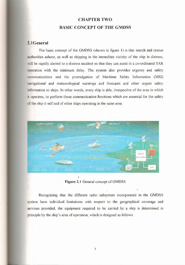
2.lGeneral
The basic concept of the GrvIDSS(shown in figure 1) is that search and rescue
authorities ashore, as well as shipping in the immediate vicinity of the ship in distress,
will be rapidly alerted to a distress incident so that they can assist in a co-ordinated SAR
operation with the minimum delay. The system also provides urgency and safety
communications and the promulgation of Maritime Safety Information (MSI)
navigational and meteorological warnings and forecasts and other urgent safety
information to ships. In other words, every ship is able, irrespective of the area in which
it operates, to perform those communication functions which are essential for the safety
of the ship it self and of other ships operating in the same area.
Figure 2.1 General concept of GrvIDSS,,
Recognizing that the different radio subsystem incorporated in the GrvIDSS
system have individual limitations with respect to the geographical coverage and
services provided, the equipment required to be carried by a ship is determined in
principleby the ship's area of operation, which is designed as follows:
5

• Sea area Al: an area within the radio telephone coverage of at least one VHF coast
station in which continuous Digital Selective Calling (DSC) alerting is available,
as may be defined by contracting government;
• Sea area A2: an area, excluding sea area Al, within the radio telephone coverage of
at least one :MF coast station in which continuous Digital Selective Calling (DSC)
alerting is available,as may be definedby contracting government;
• Sea are A3: an area excluding sea areas Al and A2, within the coverage of an
INMARSAT geostationary satellite in which continuous alerting is available;and
• Sea area A4: an area outside sea area Al, A2 and A3.
Figure 2.2 Sea areas
"'• GMDSS Shipboard Equipment of Those Areas
1. Area Al •• VHF radiotelephone.
• VHF DSC on Channel 70.
• VHF DSC watch receiver.
• SART (One).
• NAVTEX receiver.
• Enhanced Group Call (EGC) equipment Required if outside NAVTEX coverage.
• SatelliteEPIRB float free,or VHF.
6

• EPIRB capable of transmitting a DSC.
• Distress alert on Channel 70 VHF.
• 2182kHz watch receiver required untill st Feb 1999.
2. AreaA2
• VHF radiotelephone.
• VHF DSC on Channel 70.
• VHF DSC watch receiver.
• SART (One).
• NAVTEX receiver.
• Enhanced Group Call (EGC) and Printer equipment required if outside NAVTEX
coverage.
• Satellite EPIRB float free.
• 2182k:Hz watch receiver plus an Automatic Signal Generating Device (ASGD)
required until 1st Feb 1999.
• MF radiotelephone with DSC.
• MF watch receiver dedicated to 2187.SkHz.
• MF DSC encoder/decoder.
3. Area A3
• VHF radiotelephone.
• VHF DSC on Channel 70.
• VHF DSC watch receiver.
• SART (One).
• NAVTEX receiver. •• Enhanced Group Call (EGC) and printer required if outside NAVTEX coverage.
• 406MHz EPIRB float free.
• 2182k:Hz watch receiver plus an Automatic Signal Generating Device (ASGD)
required until 1st Feb 1999.
• MF radiotelephone with DSC.
• MF watch receiver dedicated to 2187.5 kHz.
• MF DSC encoder/decoder.
7

• INMARSAT MES.
• OR instead of above: MF/HF plus DSC (scanning watch receiver plus narrow band
direct printing (NBDP)).
4. Area A4
• VHF radiotelephone.
• VHF DSC on Channel 70.
• VHF DSC watch receiver.
• SART (One).
• NAVTEX receiver.
• 406MHz EPIRB float free.
• 2182kHz watch receiver plus an Automatic Signal Generating Device (ASGD)
required until 1 st Feb 1999.
• MF radiotelephone with DSC/NBDP.
• Telex (NBDP).
• MF/HF scanning DSC watch receiver.
The following type of radio communications mode is the minimum complement
of services that can be offered to meet GMDSS Sea Area A-4 guidelines:
Table 2.1 Radio communications mode
Frequency band DSC alerting R/T Distress\safety NBDP (broad cast)~
traffic frequency frequencyfrequency
HF4 4207.5 kHz 4125.0 kHz 4210.0 kHz..,
:IHF6 6312.0 kHz 6215.0 kHz 6314.0 kHz
I HF8 8414.5 kHz 8291.0 kHz 8416.5 kHz
:ı HF 12 12,577.0 kHz 12,290.0 kHz 12,579.0 kHz
HF 16 16,804.5 kHz 16,2\.20.0 kHz 16,806.5 kHz
8
2.2 Communications Functions in the GMDSSThe GMDSS comprises the following communications functions as required by
regulation IV/4. These functions are individually performed by the radio subsystem set
out in chapter3 and 4.
2.2.1 Alerting
Distress alerting is the rapid and successful reporting of a distress incident to a
unit, which can provide or co-ordinate assistance. This would be a Rescue Co
ordination Center (RCC) or another ship in the vicinity. When an alert is received by an
RCC, normally via a coast station or coast earth station, the RCC will relay the alert to
SAR units and to ships in the vicinity of the distress incident. A distress alert should
indicate the ship's identification and the position of the distress and, where practicable,
its natural and other information, which could be used for, rescue operations.
The communication arrangements under the GMDSS are designed to enable
distress alerting to be performed in all three directions ship-to-shore, ship-to-ship and
shore-to-ship- in all sea areas. The alerting function is based on both satellite and
terrestrial means and the initial distress alert is primarily transmitted in the ship-to-shore
direction. When the distress alert is transmitted by DSC on VHF, MF or HF, ships
within DSC range of the ship in distress will also be alerted (ship-to-ship alerting).
A distress alert is normally initiated manually and all distress alerts are
acknowledged manually. When a ship sinks, a float free satellite Emergency Position
Indicating Radio Beacon (EPIRB) is automatically activated. Ships operating"'exclusively in sea area Al may, in lieu of satellite EPIRRB, use VHF EPIRBs on
channel 70. •
The relaying of a distress alert from an RCC to ships in the vicinity of a distress
incident is made by satellite communication or by terrestrial communication using
appropriate frequencies. In either case, to avoid all ships in a large sea are being alerted,
an "area call" is normally transmitted so that only those ships in the vicinity of the
ess incident are alerted. On receipt of a relayed distress alert, ships in the area
addressed are required to establish communication with the RCC concerned to enable
9

the assistance to be co-ordinated. Chapter 4 deals with the operational procedure and
routing of the distress alert.
2.2.2 SAR Co-ordinating CommunicationsIn general these are the communications necessary for the co-ordination of ships
and aircraft participating in a search and rescue operation following a distress alert and
include communication between RCCs and any "On-Scene Commander (OSC)" or
"Co-ordinator Surface Search (CSS)" in the area of the distress incident.
For SAR operations messages are transmitted in both directions, as distinct from
"alerting", which is generally the transmission of specific message in one direction
only, and distress and safety traffic by radiotelephony and direct-printing telegraphy
will normally be used for passing such a messages.
The techniques, which are available for SAR co-ordinating communications, are
radiotelephony or direct-printing telegraphy or both. These communications can be
carried out by terrestrial or satellite means, dependent upon the equipment fitted on the
ship and the sea area in which the incident occurs.
2.2.3 On-Scene CommunicationOn-scene communications normally take place in the MF and VHF bands on
frequencies designated for distress and safety traffic, by radiotelephony or direct
printing telegraphy. These communications between the ship in distress and assisting
units relate to the prevision of assistance to the ship or the rescue of survivors. When@I
aircraft are involved in on-scene communications they are normally able to use 3023,
4125 and 5680 kHz. In addition, SAR aircraft can be provided with equipment to•communicate on 2182 kHz or 156.8 MHz or both, as well as on maritime mobile
frequencies.
2.2.4 LocatingLocating is the finding of a ship/aircraft in distress or its survival craft or
survivors. In the GMDSS this function is performed by means of9 GHz SAR radar
;ponders (SARTs) by the ship in distress or its survivors, whose position is
- f Med when the SART is interrogated by the searching unit's 9 GHz radar. Use of
10

the frequency 121.5 Mflz in most satellite EPIRBs is provided for homing by
aeronautical SAR units.
2.2.5 Promulgation of MSI
Ships need to be provided with up-to-date navigational warnings and
meteorological warnings and forecasts and other urgent safety information (MSI). MSI
is made available by narrow-band direct-printing telegraphy broadcasts, using forward
error correction on the frequency 518 kHz (international NAVTEX service) and, for
ships navigate beyond the NAVTEX coverage, by broadcast via INMARSAT Enhanced
Group Call (EGC) system (known as the international safety NET system). A high seas
MSI broadcast system by HF direct-printing telegraphy is under development. Details
for MSI systems are given in section 3.6.
2.2.6 General Radio CommunicationsGeneral radio communications in the GMDSS are those communications
between ship stations and shore-based communication networks, which concern the
management and operation of the ship and may have an impact on its safety. These
communications can be conducted on any appropriate channel, including those used for
public correspondence. Examples are orders for pilot and tug services, chart
replacement, repairs, etc.
2.2.7 Bridge-to-Bridge CommunicationsBridge-to-bridge communications are inter-ship safety communications
conducted from the position from which the ship is normally navigated. Normally"'performed by VHF radiotelephony.
•
11

CHAPTER THREE
INMARSAT SYSTEM IN GMDSS
3.1 General
• Satellite Communications
Satellite communications are particularly important elements of the GMDSS.
The INMARSAT system which employs geostationary satellites and operates in
the 1.5 and 1.6 GHz band (L band) provide ships fitted with ship earth station with a
means of distress alerting and a capability for two-way communication using direct
printing telegraphy and radio telephony. L-band satellite EPIRBs are also used for
distress alerting. The INMARSAT safety NET system is used as a main means to
provide MSI to areas not covered by the NAVTEX system.
A polar orbiting satellite system, orbiting in the 406 MHz band using satellite
EPIRBs (COSPAS-SARSAT system), provides one of the main means of distress
alerting and determining the identity and position of the ship in distress or its survivors
in the GMDSS.
• Terrestrial Communications
With terrestrial communications, DSC forms the passes of distress alerting and
safety communications. Distress and safety communications following a DSC call can
be performed by radiotelephony or direct-printing telegraphy or both.
"• Long-Range Service•Use of HF provides a long-range service in both the ship-to-shore and shore-to-
ship directions. In areas covered by INMARSAT it can be used as an alternative to
satellite communications and out side these areas it provides the only long-range
communication capability. Frequencies have been designated in the 4, 6, 8, 12 and 16
MHz bands for this service.
12

edium-Range Service
MF radio communications provide the medium range-service. In the ship-to-
re, ship-to-ship and shore-to-ship directions 2187. 5 kHz will be used for distress
alert and safety calls using DSC, and 2182 kHz will be used for distress and safety
traffic by radiotelephony, including SAR co-ordinating and on-scene communications.
2174.5 kHz will be used for distress and safety traffic by direct-printing telegraphy.
Short-Range Service
VHF provides short-rang service on the frequencies:
156.525 Mlfz (channel 70) for distress alert and safety calls using DSC, and
156.8 Ml-lz (channel 16) for distress and safety traffic by radiotelephony, including
SAR co-ordinating and on-scene communications.
There is no short-range direct-printing telegraphy service on VHF.
3.2 INMARSAT Systems3.2.1 Introduction
INMARSAT grew out of an idea that originated within IMO in 1966. Following
extensive study by IMO experts an international conference was convened which, after
three sessions on 3 September 1976, unanimously adopt the convention and operating
agreement on the International Maritime Satellite organization (INMARSAT).
According to its convention, INMARSAT is "to make provision for the space segment
necessary for improving maritime communications, there by assisting in improving
distress and safety of life at sea communications''.
The INMARSAT system has three major components: the space segment
provided by INMARSAT, the Coast Earth Stations (CESs) provided by INMARSAT
signatories and Ship Earth Stations (SESs).
The nerve center of the system is the Operations Control Center (OCC), located
at INMARSAT's headquarters in the United Kingdom. The OCC is responsible for
controlling the INMARSAT system operation as a whole. Operating 24 hours a day, it
13

co-ordinates a wide range of activities. The OCC also arrange the commissioning of
SESs upon application by the ship owner.
3.2.2 Safety Advantages of Satellite Services
Some of the advantages of maritime satellite communications for safety uses are:
• Satellite communications are fast, reliable and of high quality. Users are not plagued
by ionospheric disturbances and crowded radio waves, which can result in delays of
hours or even days when making a call with conventional radio communications.
• Satellite communications are simple and easy to use. A ship equipped with a ship
earth station can send a telex or make a telephone call directly to shore or to other
satcom-equipped ships as easily as if the call were being made between two offices
ashore.
• Maritime satellites provide near-global coverage (to about 75 degrees of latitude),
which means that a ship with a ship earth station can be virtually anywhere on the
navigable waters of the world and still send a distress alert or be reached by
telephone or message communications.
• A ship equipped with a ship earth station can be reached 24 hours a day.
• INMARSAT has granted access to its system by land-based ship earth stations at
RCCs, in accordance with n,rovisions in the ITU Radio Regulations, which permit
SESs at RCCs to communicate with other stations of the same category for distress
and safety purposes. INMARSAT-A SESs are installed at RCG:s in Argentina,
Bulgaria, China, Germany, Greece, Ireland, Israel and the United Kingdom. With an
INMARSAT ship earth station, safety authorities have virtually instant and
high-quality communications available for contacting help and co-ordinating rescueoperations.
• A distress message generator (DMG) can be built into the software of ship earth
stations. Some ship earth stations already have this. This feature permits a distress
14
message, which includes ship's position, course, speed and particulars of the distress,
etc., to be sent automatically, without the need to prepare the entire message at the
time of the emergency.
• The INMARSAT system can accommodate additional safety features, such as
automatic ship reporting at regular intervals. A ship polling system can be used so
that shore authorities could obtain ship's position information automatically. Many
ship earth station manufacturers already offer an interface between navigation
equipment and the ship earth station, which will allow this. Information relating to
the ship's heading and speed can be sent to or retrieved by authorized users on shore.
• The INMARSAT system provides business communications for ships and meets
many of the requirements specified for the GMDSS and included in amendments to
the SOLAS Convention. Satellite communications, with their high reliability, simple
operation and ability to handle a range of operating modes, are being enthusiastically
welcomed aboard ships for their business, safety and social benefits.
• Satellites bring rapid, reliable communications to the aid of the mariner, to help
avoid danger and to provide a means for summoning assistance when all else fails.
The ability to communicate with a vessel anywhere in the world, at any time of day,
and to know that you can be advised immediately of any difficulties, should appeal to
all owners and operators of ships. The ability to contact a rescue co-ordination center
or technical experts ashore for immediate assistance should appeal to every seafarer.
3.2.3 Space Segment
Four satellites in geostationary orbit 36,000 km above the •.equator cover for
ocean regions, namely AOR-E (Atlantic Ocean Region-East), AOR-W (Atlantic Ocean
region-west), IOR (Indian Ocean Region) and POR (Pacific Ocean Region), and
provide near-global coverage.
3.2.4 Coast Earth Stations
The CESs provide the link between the satellites and terrestrial
telecommunications networks. Currently, all CESs are owned and operated by
telecommunications carriers. A typical CES consists of a parabolic antenna about 1 lm15

to 14m in diameter, which is used for transmission of signals to the satellite at 6 GHz
and for reception from satellite at 4 GHz. The same antenna or another dedicated
antenna is used for L-band transmission (at 1.6 GHz) and reception (at 1.5 GHz) of
network control signals. The type of communication service provided varies depending
on the CES. Designated for each ocean area for each communication service (i.e.
telephone, direct-printing telegraph, etc.) service as a Network Co-ordination Station
CS) which assigns communication channels, on demand, to SESs and other CESs and
monitors signals transmitted by these stations.
3.2.5 Ship Earth Stations
The requirements for the SESs in the GMDSS can be met by INMARSAT SESs
capable of two-way communications, such as INMARSAT-A, INMARSAT-B and
INMARSAT-C SESs.
3.2.6 INMARSAT-A SES
An INMARSAT-A SES consists of two parts, Above-Deck Equipment (ADE)
and Below-Deck Equipment (BDE) (figure 3. 1 ). The BDE includes a parabolic antenna,
about 0.85m to 1.2m in diameter, mounted on a plate form and stabilized so that the
antenna remains pointed at the satellite regardless of ship motion. It also includes a sold
state L-band power amplifier, an L-band low-noise amplifier, a diplexer and a low-loss
protective radome. The ADE consists of an antenna control unit; communications
electronics used for transmission, reception, access control and signaling; and telephone
and telex equipment.
•
Figure 3.1 Example ofINMARSAT-A SES
16
The new generation ofINMARSAT-A equipment currently begins produced by
manufacturers is smaller and easier to use than earlier models. ADE is now available
weighing less than 50 kg, making it suitable for installation in most types and sizes of
vessels and yachts. Many of the current systems are modular in design and allow the
addition of optional equipment such as facsimile, data and slow-scan television, etc.
some BDE has a microcomputer with Visual Display Unit (VDU), alphanumeric
keyboard, hard-copy printer and modem. The computer can be used to prepare telex
messages with the ease of modern word-processing equipment. Messages can be
composed, edited and transmitted directly from the screen or stored for later
transmission. In some models, the computer memorizes the satellite's co-ordinates and
CES tariffs and automatically routes the call in the most economical way.
With additional facilities, users have modified their terminals to allow
automated vessel reporting. Those involved in vessel management on shore can dial the
ship at any time of the day or night and automatically receive information as to its
position, heading, etc., as well as data on its cargo and operation-all without disturbing
or distracting the crew. A distress message generator is normally built in to a terminal
(mostly a software modification) for storage of basic essential vessel information and
automatic transmission in a distress situation.
3.2. 7 INMARSAT-B SES
The INMARSAT-B SES is a digital complement of INMARSAT-A SES
developed to replace INMARSAT-A SES equipment in the future. It provides the same
communications services as an INMARSAT-A SES.
The INMARSAT satellite system provides nearly global coverage with a•.constellation of geostationary satellites. The original INMARSAT-A service is due to
be phased out in the coming years. Its re-placement, INMARSAT-B service, offers
high-quality Voice, Telex, Data and Group III fax capabilities.
INMARSAT-B service rates are significantly less than INMARSAT-A service,
making it a must for customers with high-volume requirements. The high-speed data
(HSD) option for the INMARSAT-B Service allows for data transfer at 56/64 kbps.
17

3.2.8 INMARSAT-C SES INMARSAT-C SESs are small, lightweight terminals designed for two-way
message communication (figure3.2). INMARSAT-C SESs can not be used for
radiotelephone communications; they operate at 600 bit/s and provide access to the
international telex/teletex networks, electronic mail services and computer databases.
This low-powered terminal with its Omni directional antenna and lightweight is a
ractical solution for installation on the smallest of vessels, there by bringing the
nefıts of satellite communications within the reach of all mariners. It will enlarge the
user community by providing equal access to exiting and emerging satellite services to
all seafarers.
Figure 3.2 Example ofINMARSAT-C SES"'
Additionally, an INMARSAT-C SES can serve as a back-up for an.INMARSAT-A SES on large ships and also fulfill potentially vital role as a fixed or
table transmitter/receiver for use on board ship or in survival craft. The Omni
directional antenna characteristics are particularly valuable for a vessel in distress as the
SES continues to operate even when the vessel is listing severely. As with the
INMARSAT-A SES, a distress message generator can be included in the terminal
software for storage of basic essential vessel information and automatic transmission in
a distress situation.
18

3.2.9 Enhanced Group Calls Receiver
The INMARSAT EGC receiver is a dedicated piece of equipment for the
reception of information by INMARSAT EGC service. It has been designed to enable
automatic continuous watch on international safety NET MSI broadcasts and
commercial INMARSAT fleet NET messages, such as superscription to news services,
etc. An EGC capability can be added to INMARSAT-A, INMARSAT-B and
INMARSAT-C SESs or it can be stand-alone receiver with its own antenna.
An EGC receiver is required in the GMDSS for all ships, which processed
beyond coverage of the international NAVTEX service.
3.3 INMARSA T Services 1. Ship-to-Shore Distress Alerting
The INMARSAT system provides priority access to satellite communications
channels in emergency situations. Each SES is capable of initiating a "request" message
with distress priority (INMARSAT priority-3 call). Any "request" message with a
distress priority indication is automatically recognized at the CES and a satellite channel
· instantly assigned. If all satellite channels happen to be busy, one of them will be
preempted and allocated to the SES, which initiated the distress priority call. The
processing of such calls is completely automatic and does not involve any human
intervention. The CES personnel, however, are notified of the reception and passing
through of a distress priority message by audio-visual alarms.
To ensure the correct treatment of distress priority request, the NCS in each
ocean region automatically monitors the processing of such calls by all other CESs in
region. In the event that any anomalies in processing are detected, the NCS will
e appropriate action to establish the end-to-end connection. In addition, the
nitoring NCS also checks the CES identity contain in the distress priority message
automatically accept the call if an identity of a non-operational CES has been
ected (which any happen due to operator error a board the vessel in distress).
The distress priority applies not only with respect to satellite channels but also to
automatic routeing of the call to the appropriate RCC. Each CES in the system is
19
required to provide reliable communication interconnection with an RCC; these national
RCCs are known as associated RCCs. The means of CES-RCC interconnection may
vary from country to country and include the use of dedicated lines or public switched
networks. Thus, any distress priority request message received at the CES is
automatically processed and passed to the associated RCC. Some CESs, due to national
consideration, pass distress priority message to special operators, who are responsible
for the subsequent routeing of the call to the appropriate RCC, or provide an option
which allows the ship board operator to contact any RCC when a satellite channel has
been assigned on the distress priority basis.
The initiation of a distress priority message in most SESs is made simple for
ship crewmembers by provision of a "distress button" or code in the SES. On activation
of this button, the equipment instantaneously transmits a distress priority message. This
single operation, a push of the "distress button", provides automatic, direct and assured
connection to a component rescue authority, there by avoiding the need for the SES
operator to select or key the telex or telephone number of the RCC and eliminating
possible human error. The establishment of this end-to-end connection, begin
completely automatic and on a priority basis, takes only a few seconds.
INMARSAT has issued technical guidelines to manufacturers for a Distress
Message Generator (DMG), which consist of SES soft ware to transmit automatically,
after the connection has been established, the distress message in a standardized format
that provides information on the vessel's identification, its position and the particular
emergency.
The procedure described above is the primary means of ship-to-shore distress
alerting in the INMARSAT system. It should be noted, however, that INMARSAT
SES-equipped ships can also contact any RCC of their choice by following the calling
procedure for routine calls. In this case, the complete international telephone/telex
number has to be selected.
A major benefit of the INMARSAT distress priority is that it eliminates the need
for dedicated frequencies to be allocated for distress and safety communications.
Distress messages made through the INMARSAT distress priority system are sent
20
through the general communication channels on an absolute priority basis to ensure an
immediate connection.
2. Shore-to-Ship Distress Alerting
Shore-to-ship alerting to groups of ships with INMARSAT-A, INMARSAT-B
or INMARSAT-C SESs but without INMARSAT safety NET capability can be
performed in the following modes:
1. "All ships call"-calls to ships in the ocean region concerned. It should be noted,
however, that due to the large coverage zones of geostationary satellite such alerting
is not very efficient, although it maybe justified under exceptional circumstances.
2. "Geographical area calls"-calls to ship navigation in a defined geographical area.
Each satellite coverage region is subdivided in to smaller areas, and the bounders of
these areas are based on NAVAREAs each having a unique two-digit area code.
SESs will automatically recognize and accept geographical area calls only if the
correct code has been input by the SES operator; the system requires the periodic
manual input of appropriate area cods; or
3. "Group calls to selected ships"-this service is provided by number of CESs in the
operator- assisted mode and allows alerting of a predetermined group ofvessels. This
service could be very useful for alerting, for example, SAR units.
As long as they are not engaged in traffic, SESs accept all incoming messages
without any differentiation of priority.
3. Shore-to-Ship Distress Alerting Through the INMARSAT Safety System
The EGC receiver can be an integral part of a SES or a completely separate unit
and it ensures a very high probability of receiving shore-to-ship distress alert messages.
When a distress priority message is received, an audible alarm will sound and it can
only be reset manually.
Accessing the INMARSAT safety NET service by RCCs requires arrangement
similar to those needed for shore-to-ship distress alerting to a standard SES. Those
21
Promulgation ofMSI (via INMARSAT Safety NET Services)
In the INMARSAT system, promulgation ofMSI is performed by means of the
INMARSAT safety NET system. Although an INMARSAT-A, INMARSAT-B or
INMARSAT-C SES can receive the safety NET broad casts, if uninterrupted receipt of
important MSI is required when the SES is engaged for other communications, then it is
essential to have a dedicated EGC reception capability for such broad casts.
Alternatively, an EGC receiver can be installed as a separate unit .
. General Radio Communications
The INMARSAT system provides ships at sea with the same types and quality
of modem communications as are available a shore. The capability for direct-dial,
automatic connection without delay using high-quality multi-mode communications is
provided by SES. Tele printers, VDUs and telephone sets, as well as facsimile machines
and data equipment can serve as peripheral equipment to SESs.
The quality and availability of general radio communications offered by the
INMARSAT system permit ship's master to rapidly consult and seek assistance on any
matter, whether of a safety or commercial nature. High-quality general communications
are therefore a valuable asset to safety at sea as well as the efficient operation of the
ship.
The following are examples ofINMARSAT services:
Direct-printing telegraphy.
Telephony.
Data communications.
Facsimile. "Slow-scan television.
Automatic data collection from ships. ••
3.4 L-band satellite EPIRBsL-band satellite EPIRBs operating through the INMARSAT system can be used
a means of alerting by ships operating in sea areas Al, A2 and A3 as an alternative to
406 MHz satellite EPIRBs.
23

The basic concept of the INMARSAT L-band satellite EPIRBs system is shown
figure 3.3. The distress signal transmitted from the float-free satellite EPIRBs on the
icated channel in the 1.6 GHz frequency (L-band) is relayed by an INMARSAT
rellite to CESs equipped with the appropriate receiver and processor equipment.
..'.
Figure 3.3 Basic concept of the L-band satelliteEPIRBsystem
The L-band satellite EPIRB provides for rapid distress alerting (in the order of
10 minutes with 1 W output power radiated by an EPIRB). Coverage up to ±70° latitude,
_o simultaneous alert within 1 O-minute time frame and the possibility of manual or
automatic entry and update of position information to the satellite EPIRB. The satellite
EPIRB can be activated either manually or automatically, by a floating free from the
sinkingship.
24
After activation, the satellite EPIRB transmits the distress message containing
ship station identity, position information and additional information, which could
used to facilitate rescue. The transmission is repeated on a pre-selected duty cycle.
itionally, unless an integrated electronic position- fixing device is included which
vides position updates, a built-in 9 GHz SART is activated for locating purposes.
After begin relayed by the satellite, the distress signal is down-converted at the
CES to the specified intermediate frequency to be transferred to the computer-aided
ti-channel receiver for satellite EPIRB identification and message decoding.
After the signal channels are identified, they are assigned to processor channels
ere the incoming signal plus noise is superimposed in the memory. Having
accomplished the necessary number of superposition which results in 2-3 dB
provement of signal-to noise ratio for every frame, the memory is read out and the
l processors, such as bit and frame synchronization, evaluation of the error
correcting code and the message print-out, are performed.
The distress message is then forwarded to an associated RCC for appropriate
on .
. 5 Sea 6003 Specifications
General
INMARSAT TIA: TA-04-060-04. Meets or exceeds all current and proposed
specifications for the INMARSAT-C Network and SOLAS/GMDSS requirements,@,
including CNl 14, IMO A.807 (19), IEC 1097-4, IEC 945, EEC EMC and CE Mark.
FCC ID: BZ6SEA6003
Protocol
Message transmission and reception with IA-5, ITA-2, and binary transfer
to/from the following destinations: Telex, PSTN (telephone and fax modems), PSDN
.25 network), EGC message reception with automatic geographical area selection,
polling and data reporting with automatic transmission of position reports down to 1 per
minute, special access codes, DNID messaging, program unreserved data reporting, pre-
25

assigned data reporting, SOLAS distress calling facilities (GMDSS). Transmit message
size: Max 32 Kbytes. Receive storage: 106 Kbytes.
Languages Available: English, Cyrillic, French and Spanish
Transceiver
Transmit Frequency: 1626.5 to 1660.5MHz.
Receive Frequency: 1525.0 to 1559.0MHz.
GPS Frequency: 1575.42MHz.
Channel Spacing: 5/2.5/1.25 kHz.
Modulation: 1200 symbols/sec BPSK.
Ambiguity Resolution: Unique Word.
Coding: R 1/2 K = 7 convolutional code. (Interleaved code symbols RX).
Data Rate: 600 bit/sec.
RX Frame Length: 8.64 seconds.
TX Signaling Access Mode: Slotted ALOHA.
TX Message Channel: TDMA & FDMA, interleaved code symbol.
Antenna Interface: Standard 50-0hm female TNC-connector.
GPS (Optional): 8 channel, I-second update rate, 15 m RMS accuracy (100 m with S/A)
Terminal Interface: Serial EIA-232-E DTE, CCITT Rec. V.24/28, 110-38400Baud IA-
5 code, DB-9F connector.
Printer Interface: Standard parallel IEEE 1284, Centronics, DB-25F connector.
1/0 Interface: NMEA 0183 version 2. 1, ArcNet 2.5 Mbit, Remote Alarm, DB-15F.
System Setup: Flash EEPROM programming from operator terminal.
Solid State Storage: 256 Kbytes SRAM, 512 Kbytes Flash."'DC Power Source: 10 to 32 V floating DC.
RX: 4.8/90 W Rx/Tx with GPS module.
Ambient Temperature: - 25°C to 55°C operating, - 40°C to 80°C storage.
Electronic Unit Mounting: Flange mounting, vertical or horizontal.
Compass Safe Distance: 0.5 m.
26
General Antenna Specifications
Type:
INMARSAT-C/GPS Omni directional, RHC polarized, G/T-23db/K, EIRP 14 dBW at
5° elevation. Coverage +90° to -15° elevation.
Ambient Temperature: - 35°C to 55°C operating, - 40°C to 80°C storage.
Relative Humidity: 95% non-condensing at 40°C.
Precipitation Up to 5 cm/hour, droplet size 0.5 to 4.5 mm.
Wind: Up to 200 km/h.
Ice: Up to 25 mm.
Vibration Operational: Random 5-20 Hz 0.005 g2/Hz, 20-150 Hz -3dB/Oct. (1.0g rms.).
Vibration Survival: Random 5-20 Hz 0.05 g2/Hz, 20-150 Hz-3dB/Oct. (1.7g rms.).
Shock: Half-Sine 20g/l lms.
Standard Capacity Antenna
Interface: Female TNC Connector.
Solar Radiation: 1200W/m2 max flux density.
Max. Transmission Length: 1 O Kbytes.
Mounting: Roof Standard 1.5" tube.
Heavy Capacity Antenna (Optional)
Interface: N Connector.
Solar Radiation: Infrared, 500W/m2.
Max. Transmission Length: 32 Kbytes.
Mounting: Roof Standard l.5"tube.•
27
CHAPTER FOUR
COMMUNICATIONS SYSTEMS
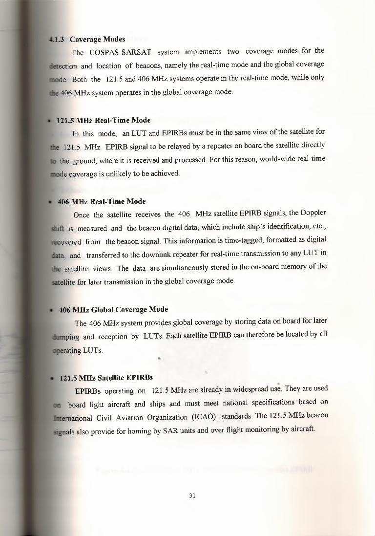
4.1 COSPAS-SARSAT System4.1.1 Introduction
The COSPAS-SARSAT system is a satellite-aided SAR system designed to
locate distress beacons transmitting on the frequencies 121.5MHz or 406 MHz. It is
intended to serve all organizations in the world with responsibility for SAR operations
whether a distress occurs at sea, in the air or in the land.
COSPAS-SARSAT is a joint international satellite-aided SAR system,
established by organizations in Canada, France, the United States and the former USSR.
The COSPAS-SARSAT system has demon started that the detection and
location of distress signals can be facilitated by global monitoring based on low
altitude satellites in near- polar orbits. It has been used successfully in a large number of
SAR operations worldwide.
Unless, as an alternative, a ship is provided with an L-band satellite EPIRB, the
carriage of a float-free satellite EPIRB operating on the frequency 406 MHz in the
COSPAS-SARSAT system is mandatory on all SOLAS ships.
• 1.2 General Concept of the System
The basic COSPAS-SARSAT system concept is given in figure (4.2). There are
at present three types of satellite beacons, namely Emergency Locator Transmitter
(ELTs) (air borne), EPIRBs (maritime) and Personal Locator Beacons (PLBs) (land).•.These beacons transmit signals that are located by COSPAS-SARSAT polar-orbiting
satellites equipped with a suitable receivers/processors. The signals are then relayed to a
ound receiving station, called a Local User Terminal (LUT), which process the
signals to determine the beacon location. An alert is then relayed, together with location
data and other information, via a Mission Control Center (MCC), either to a national
CC, to another MCC or to the appropriate SAR authority to initiate SAR activities.
28

Doppler shift (using the relative motion between the satellite and the beacon) is
used to locate the beacons. The carrier frequency transmitted by the beacon is
reasonably stable during the period of mutual beacon-satellite visibility. The frequencies
currently in use are 121.5 "MH.z (international aeronautical emergency frequency) and
406.025 l\1Hz. The 406 l\1Hz beacons are more sophisticated than the 121.5 MHz
beacons because of the inclusion of identification codes in the messages, but complexity
is kept to a minimum. To optimize Doppler location, a low-altitude near-polar orbit is
used. The low altitude results in a low up link power requirement, a pronounced
Doppler shift, and short interval between successive passes. The near-polar orbit results
in complete world coverage over a period of time.
The Doppler location concept provides two positions for each beacon: the true
position and its mirror image relative to the satellite ground track. This ambiguity is
resolved by calculations that take into account the earth's rotation. If the beacon
frequency stability is good enough, as with MHz beacons 406 MHz beacons, which are
designed for this purpose, the true solution is determined over a single pass. In the case
of I 2 I . 5 beacons, the ambiguity is resolved by the results of the second pass if the first
attempt is unsuccessful. The improved performance of 406 l\1Hz satellite EPIRBs is thereason tbese deviceswere selected for the GMDSS.
Figure 4.1 COSPAS-SARSAT satellites
29
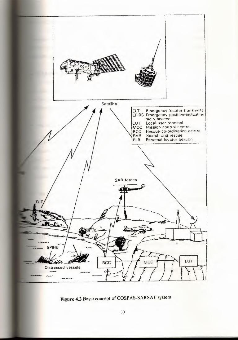
I. ·- -· -ıELT Emergency locator trans mitte;
EPIRE, Emergency position-indicatingradio beacon
LUT local user terminal IMCC Mission control centreRCC Rescue co-ordination centreSAR Search and rescue IPLB Personal locator bcacoı~---·i
\ I\. i
Distressed vessels
Figure 4.2 Basic concept ofCOSPAS-SARSAT system
30
1.3 Coverage Modes
The COSPAS-SARSAT system implements two coverage modes for the
ection and location of beacons, namely the real-time mode and the global coverage
e. Both the 121.5 and 406 MHz systems operate in the real-time mode, while only
406 MHz system operates in the global coverage mode.
121.5 MHz Real-Time Mode In this mode, an LUT and EPIR.Bsmust be in the same view of the satellite for
121. 5 MHz EPIRB signal to be relayed by a repeater on board the satellite directly
the ground, where it is received and processed. For this reason, world-wide real-time
e coverage is unlikely to be achieved.
406 MHz Real-Time Mode Once the satellite receives the 406 MHz satellite EPIRB signals, the Doppler
is measured and the beacon digital data, which include ship's identification, etc.,
vered from the beacon signal. This information is time-tagged, formatted as digital
and transferred to the downlink repeater for real-time transmission to any LUT in
satellite views. The data are simultaneously stored in the on-board memory of the
ellite for later transmission in the global coverage mode.
406 MHz Global Coverage Mode The 406 MHz system provides global coverage by storing data on board for later
ing and reception by LUTs. Each satellite EPIRB can therefore be located by all
121.5 MHz Satellite EPIRBs ..EPIR.Bs operating on 121.5 MHz are already in widespread use. They are used
board light aircraft and ships and must meet national specifications based on
ernational Civil Aviation Organization (ICAO) standards. The 121.5MHz beacon
· als also provide for horning by SAR units and over flight monitoring by aircraft.
31
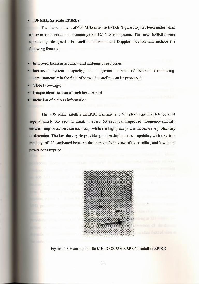
• 406 MHz Satellite EPIRBs
The development of 4061\1Hz satellite EPIRB (figure 3.5) has been under taken
to overcome certain shortcomings of 121.5 1\1Hz system. The new EPIRBs were
specifically designed for satellite detection and Doppler location and include the
following features:
• Improved location accuracy and ambiguity resolution;
• Increased system capacity, i.e. a greater number of beacons transmitting
simultaneously in the field of view of a satellite can be processed;
• Global coverage;
• Unique identification of each beacon; and
• Inclusion of distress information.
The 406 1\1Hz satellite EPIRBs transmit a 5 W radio frequency (RF) burst of
approximately 0.5 second duration every 50 seconds. Improved frequency stability
ensures improved location accuracy, while the high peak power increase the probability
of detection. The low duty cycle provides good multiple-access capability with a system
capacity of 90 activated beacons simultaneously in view of the satellite, and low mean
power consumption.
••
Figure 4.3 Example of 4061\1HzCOSPAS-SARSAT satellite EPIRB
32

An important feature of the new satellite EPIRBs is the inclusion of a digitally
aıcoded message, which may provide such information as the country of origin of the
unit in distress, identification of the vessel or aircraft, nature of distress and, in addition,
,r satellite EPIRBs coded in accordance with the maritime location protocol, the ship's
position as determined by it navigation equipment.
Most satellite EPIRBs are, as recommended, dual-frequency 121.5/406MHz
beacons, through the inclusion of the frequency 121.5 MHz is not mandatory. This
aıables suitable SAR units to home in on the 121.5 transmission and permits over flight
monitoring by aircraft. This type of homing facility, if provided, is indicated to the
rescue authorities by the message. As SARTs have limited range of operation (5
nautical miles), consideration is being given to requiring all maritime satellite EPIRBs
operate on the frequencies 121.5MHz and 406 MHz.
Depending on the type of beacon (maritime, airborne or land), beacons can be
activated either manually or automatically.
.• 1.4 COSPAS-SARSAT Low Earth Orbit Search and Rescue (LEOSAR) System
COSPAS-SARSAT has demonstrated that the detection and location of 406
MHz and 121.5 MHz distress beacon signals can be greatly facilitated by global
monitoring based on low-altitude spacecraft in near-polar orbits. Complete, yet non
continuous coverage of the Earth is achieved using simple emergency beacons operating
on 406 MHz to signal a distress. The non-continuous aspect of the coverage occurs
because the polar orbiting satellites can only view a portion of the earth at any given
time. Consequently the System 'cannot produce distress alerts until the satellite is in a
position where it can see the distress beacon. However, since the satellite onboard 406
MHz processor includes a memory module, the satellite is able to store distress beacon
information and rebroadcast it when the satellite comes within view of a LUT, thereby
oviding global coverage. With the older type of beacons operating at 121.5MHz, the
stem coverage is neither global nor continuous because detection of the distress
depends on the availability of a ground receiving station in the satellite field of view at
same time that the satellite receives the beacon signal.
33

As described above, a single satellite, circling the earth around the poles,
·entually views the entire Earth surface. The "orbital plane", or path of the satellite,
remains fixed, while the earth rotates underneath it. At most, it takes only one half
otation of the Earth (i.e. 12 hours) for any location to pass under the orbital plane. With
a second satellite, having an orbital plane at right angles to the first, only one quarter of
a rotation is required, or 6 hours maximum. Similarly,as more satellites orbit the Earth
· different planes, the waiting time is further reduced. The COSPAS-SARSAT System
esign constellation is four satellites, which provide a typical waiting time of less than
one hour at mid-latitudes.
The LEOSAR system calculates the location of distress events using Doppler
processing techniques. Doppler processing is based upon the principle that the
frequency of the distress beacon, as "heard" by the satellite instrument, is affected by
the relativevelocity of the satellite with respect to the beacon. By monitoring the change
of the beacon frequency of the received beacon signal and knowing the exact position of
the satellite, the LUT is able to calculate the location of the beacon.
Figure 4.4 LEOSAR satellites
34

1.5 Space Segment The SAR instrumentation on board the COSP AS and SARSAT satellites
rates in the following modes:
Real-time mode: 121.5 repeater;
Real-time mode: 406.025 MHz data processing and downlink; and
Global coverage mode: 406.025 MHz stored data transmission.
The equipment in the board the satellite consists of the following basic sub
assemblies:
121.5 MHz receiver;
406.025 MHz receiver/processor and memory unit; and
• 1544.5 MHz downlink transmitter.
• 121.5 MHz Receiver This unit has a bandwidth of 25 kHz. Automatic Level Control (ALC) ıs
provided to maintain a constant output level.
• 406.025 MHz Receiver/ Processor The functions of the receiver/processor are as follows:
• Demodulating the digital messages received from beacons;
• Measuring the received frequency; and
• Time-tagging the measurement.
All these data included in the output signal frame are modulated for down
linking to LUTs. The signal frame is transmitted at 2,400 Bits/second in the real time
mode and also stored in memory for later transmission by the global coverage mode. In
the global coverage mode, the on-board memory is dumped in the same format and at
the same bit rate as real-time data. LUTs thus directly receive the stored beacon
messages acquired during an entire orbital revolution. If a new beacon signal is received
during the stored memory dump, the dump is interrupted so that the signal can be
processed and the resultant message interleaved with the stored data. Appropriate flag
35
indicate whether the data are real-time or stored and the time at which full playback
the stored data was accomplished.
1544.5 MHz Downlink TransmitterThe 1544.5 MHz downlink transmitter accepts input from the 406 MHz
receiver/processor and receiver(s) operating on the other COSPAS-SARSAT band(s)
121.5 MHz and 243 MHz), adjusts the relative power level in accordance with ground
command, phase modulates low-frequency carrier with the composite signal, multiplies
the frequency to produce 1544.5 MHz, amplifiers the power level and drive the satellite
downlink antenna .
. 1.6 Local User Terminals and Mission Control Centers
The configuration and capabilities of each LUT vary to meet specific
requirements of countries, but the COSP AS and SARSAT satellite downlink signal
formats ensure interoperability between the various satellite and all LUTs meeting
COSPAS-SARSAT specifications.
There are tow types ofLUTs, those, which process 121.5 MHz, and 406 MHz
signals and those, which process 406 MHz, signals only.
Figure 4.5 is block diagram of typical COSPAS-SARSAT LUT. The antenna
and receiving system pick up the signal, which is down-converted to an intermediate
frequency (IF) and linearity demodulated to produce the composite baseband spectrum,
which is filtered and separated into the various bands of interest. As the signal is
received, the processing of each band is accomplished according to the specific
capabilities of the LUT. The option for LUT configuration incorporating analogue tape
recorders provides a back-up mode in the event of processor failure.
For the 121.5 MHz signal, each transmission is detected and the Doppler shift is
calculated. A beacon location is then determined using these data. All 406 MHz data
received from the satellite memory on each pass can be processed within a few minutes
of pass completion.
36

j~ ,-----, İJı
ıs:::ı::N_._
J
.-.i--....ı.ı
I I
1••
ı:tı orD on I:$q qo o e .(""ı~
I
37
MCCs have been set up in each country operating at lest on LUT. Their main
ctions are to collect, store and sort the data from LUTs and other MCCs, and to
vide such data to SAR networks (see figure 4.6). Most of the data handled consist of
following:
Alert data is the generic term for COSPAS-SARSAT 121.5 and 406 MHz data
derived from EPIRB information. Alert data comprise the beacon location and (for
406 MHz satellite EPIRBs) other information such as beacon identification data and
other coded information.
System information is primarily used to maintain efficient operation of the COSP AS
SARSAT system and to provide users with as accurate and timely alert data as
possible. It consists of tabulated data (ephemeris and time calibration) used to
determined beacon locations, the current status of all subsystems, and co-ordination
message required to operate the COSP AS-SARSAT system.
The COSP AS Mission Control Center (CMC) in Moscow is responsible for co
ordinating all COSPAS activities and provides the link via the SARSAT MCCs for all
interaction with the SARSAT system. The CMC computes and sends COSPAS satellite
ephemeris data to other MCCs and LUTs, and receives, processes and transmits
SARSAT ephemeris and time calibration data received from the SARSAT MCC to the
COSP AS MCCs and LUTs.
A designated MCC in the United States (USMCC) acts as a focal point for the
co-ordination of SARSAT satellite operations. It calculates 406 MHz satellite EPIRB
locations using stored data received from LUTs, distributes ephemeris data, processes
time calibration data (required for use of SARSAT 406 MHz data), and forwards the
appropriate results to other MCCs. The USMCC acts as the main system operational
contact point between the SARSAT system and the CMC.
38
2. EPIRB detection probability for 'the 406 MHz satellite EPIRB is defined as the
probability of detecting and decoding at least four individual message bursts during
a single satellite pass so that a Doppler curve-set estimate can be generated by the
LUT. At 121.5 MHz, EPIRB location probability is defined as the probability of
location during a satellite pass above 10° elevation with respect to the beacon.
EPIRB location probability relates to the two solutions ("true" and "mirror") and not
to a single unambiguous result.
3. EPIRB location error is defined as the difference between the location calculated by
the system using measured Doppler frequencies and the actual location.
Ambiguity resolution probability is defined as the ability of the system to select the
e" rather than the "mirror" location.
city is defined as the numbers ofEPIR.Bs in common view of the spacecraft,
ich the system can process simultaneously.
· - cation time is the period from activation of an EPIRB (i.e. first transmission)
reception of a valid alert message by the appropriate RCC.
rmance of the COSP AS-SARSAT system
ıt9!:tem performance characteristics are given in table 4. 1.
at 121.5 MHz is highly sensitive to EPIRB spectral" -.tPnstics. The values given below were confirmed by statistical analysis of over
beacons during the development and experiment phase.
40

Table 4.1 system performance characteristics
Characteristic 121.5 MHz 406MHz
Detection probability (not applicable) 0.98
Location probability 0.9 0.9
Location accuracy 17.2 km 90% within 5 km
Ambiguity resolution 0.73 0.96
Capacity 10 90
I. Coverage: the 12.1 MHz system operates in real-time only, while the 406 MHz
system operates in both real-time and global modes. The overall coverage is
provided by the COSPAS-SARSAT system in real-time mode is determined by the
number and positions of LUTs, each covering an area with a radius of
approximately 2,500 km. In the global coverage mode using 406 MHz satellite
EPIRBs, complete world coverage is achieved.
2. Notification time depends on the following parameters:
Satellite constellation;
LUT configuration;
Beacon location relative to an LUT;
Beacon latitude; and
Ground communication network.
4.3 Operational ProceduresThis section provides a description of alert data and system information and
general description of data flow.
4.3.1 Alert DataAlert data users are defined as those responsible for SAR operations; system
information users are primarily organizations with technical responsibility for the
COSPAS-SARSAT system (MCCs, LUT operators, and managers of ground segment
facilities).
41
Alert data are of two types: coded beacon-generated messages aıtô LUT/MCC
enerated alert messages. Signals transmitted by activated EPIRBs provide the initiali
input, which triggers the generation of alert messages. Once the incoming coded EPIRB
message has been received and processed by the LUTs, the alert data are forwarded to
the national MCC for distribution.
Each MCC distributes alert data according to its own requirements and
procedures to any country within its service area, which has greed to accept such data.
These data are given to SAR authorities so that immediate SAR action can be taken.
Additionally, any MCC receiving alert data relating to an EPIRB within another MCCs
service area or elsewhere in the world relays that information to the appropriate MCC or
SAR authority.
4.3.2 System informationThe term system information covers five types of system messages- ephemeris
messages, time calibration messages, telemetry data, satellite command and co-
ordination messages:
• Ephemeris or orbits vector information is used to acquire and track the satellite and
to compute EPIRB positions.• Spacecraft time calibration is vital for the accurate determination of EPIRB
locations.• Telemetry data provides for information on the status of the on-board SAR
instruments.• Satellite command messages are transmitted on up link during the post-launch
checkout procedure to correct faults or out-of-limit conditions. . • Co-ordination messages are used to communicate general information required for
COSPAS-SARSAT system operation.
4.3.3 Message FormatsMessages between MCCs are sent specific format permitting automatic
processing and retransmission, while messages between their LUTs are formatted in
42

rdance with national requirements. Standard message formats are used to transmit
data to RCCs outsides the COSP AS-SARSAT system.
Communication NetworkEach MCC transfer alert data and system information to ground system elements
service area according to communications network requirements and
How the global area network works
Take a TV crew's video package as an example:
First, software running on the notebook PC takes the output from the digital
rideo and compresses it to a more manageable size.
The resulting compressed file is then transferred from the notebook to the
mobile satellite unit, which transmits it as a stream of digital information over the
INMARSAT satellite network to the nearest land earth station (LES). At the LES it
joins the telecoms operator's ISDN backbone network. From there, it can:
• Travel across the TV company's private wide area network (WAN)
• Be sent across the public ISDN network, or
• Pass through the Internet, perhaps to the broadcast company's password-protected
web site.
Whichever route the message is sent, it takes just a few minutes for the file to"' amve at the newsroom computer on the other side of the world. There, it is
decompressed and ready for use in the next broadcast.
The latest breakthrough in INMARSAT's growing range of mobile e
communications. All in a notebook-sized package weighing about 4kgs. With 20 years'
experience in leading-edge mobile satellite technology, trust INMARSAT to keep you
networked everywhere business takes you.
43

Because it is satellite based, INMARSAT's Global Area Network can extend
company's IT reaches anywhere and everywhere, on any continent. And because it
dies the latest in 64kbps ISDN and IP technology the connection can be seamless
on-line for as long as it's needed
AR S:A't SAT£LU1'E 'ElWORK' .~-z
,,,..~,,.
Figure 4.7 Communicationnetwork
The three common elements are:The INMARSAT satellite network: The gateway to a fixed network: The Mobile
atcoms Unit (MSU)
4.4Digital Selective Calling (DSC) System4.4.1 Introduction
Digital Selective Calling (DSC) is an integral part of the GMDSS and is used for
ransmitting distress alerts from ships and for transmitting the associated
acknowledgment from coast stations. It is , also used by ships and coast stations for
relaying distress alerts and for other urgency and safety calls. Trials of DSC systems
were co-ordinated by the CCIR Interim Working party 8/10 during 1982-1986 and
included tests of the HF, MF and VHF DSC systems.
44

Advantages of Digital Selective Calling
A DSC-equipped VHF radio has all the features of your current VHF radio. In
ition, it lets you participate in GMDSS and provides you with these convenient,
ety-oriented features:
Includes a capability to send automatic distress .alerts
Achieves greater range for distress alerts and other DSC calls
Operates similar to a phone
Makes direct ship-to-ship calls avoiding calling channel congestion
Automatically alerts to incoming calls including notice of sudden storm warnings
and distress alerts.
DSC makes a VHF radio work more like a telephone. It allows boaters to send a
"tal call directly to another DSC-equipped vessel or shore station, much like a
on-to-person telephone call. Channel 70 has been set aside as the VHF/DSC digital
channel. Once the DSC call has been confirmed, both parties are automatically
.itched to a working voice channel.
45
4.3 Basic Description of DSC
Technical characteristicsThe system is a synchronous system using a ten-unit error-detecting code. The
ormation in the call is presented as a sequence of seven-unit binary combinations.
The classes of emission, frequency shifts and modulation rates are as follows:
FIB or J2B 170 Hz 100baud for use on HF and MF channels. When frequency-shift
keying is effected by applying audio signals to the input of single-side band
transmitters (J2B), the center of the audio-frequency spectrum offered to the
transmitter is 1700 Hz. a pre-emphasis of 6 dB/octave with frequency -shift of
~'a.\\'\\%~\ı\)-ı;:,'a,t"Ç\~t\.C)t \ı~~ C)t\~ ı;:,\\'a.t\t\~\~·.
- The frequency-shift is between 1300 Hz and 2100 Hz, the sub-carrierbeing at
1700;
The frequency tolerance of the 1300 Hz and 2100 Hz tons is ±lOHz;
The modulation rate is 1,200 baud; and
The modulation index is 2.0 ± 10%.
Operational ProceduresCCIR gives operational procedures of the DSC system. The content of a DSC
includes the numerical address of the station (or stations) to which the call is
mitted, the self-identification of the transmitting station and a message which
ııarnains several fields of information indicating the purpose of the call.
Various types ofDSC calls are available, being either distress and safety-related
or "commercial" calls (to indicate that a commercial communication, e.g. a
bony or telegraphy call, etc., is required). In the case ofVHF, automatic connection
e public network can also be established through suitably equipped coast stations.
The receipt of a DSC call by a receiving station is accompanied by a suitable
lay or printout of the address, the self-identification of the transmitting station and
content of the DSC message, together with an audible or visual alarm or both for
in categories of calls (e.g. for distress and safety related calls).
The transmission speed of a DSC call is 100 baud on MF and HF and 1,200 baud
VHF. Error-correction coding is included involving the transmission of each
acter twice, together with an overall message-check character. The duration of a
e DSC call varies between 6.2 and 7.2 seconds on MF and HF or 0.45 and 0.63
nds on VHF depending on the type ofD'sC call transmitted.
For distress and safety operations simplex frequencies are used, there being one
ency in the MF band, five in the HF bands and one in the VHF band. For
ercial operation at MF and HF paired frequencies are used, but at VHF the
plex channel 70 is used for both distress and safety and commercial calling.
In order to increase the probability of a DSC distress relay being received it is
ıed several times to form a distress call attempt. On MF and HF two types of
ess call attempts may be used, either a single frequency call attempt (five46
47
tive DSC distress calls in one frequency) or a multi-frequency call attempt (up
consecutive DSC distress calls dispersed over any of the six DSC distress
encies- one on MF and five on HF). On VHF only a single-frequency call attempt
since there is only one VHF DSC frequency (channel 70). VHF and MF/HF
s calls may be transmitted simultaneously.
The various distress and safety-related calls by DSC are itemized below,
er with a description · of the content of the message for each type of call. In
· ion to the message content, each DSC call also contains other information, which is
displayed to the receiving station but which is used to ensure the technical integrity
DSC system.
Distress Call (Alert)DSC distress calls are transmitted by a ship in distress and will be received by all
ly equipped ships and coast stations within propagation range of the radio
A DSC distress call contains various items of information including the self
tification of the ship in distress, which will be displayed to the receiving station.
· s information will either be automatically included in the transmitted DSC distress
or will be inserted by the operator prior to transmission. When time does not permit
insertion of any information, "default" information will be included automatically.
Distress AcknowledgmentDistress acknowledgments by DSC are-normally transmitted manually by coast
stations in response to a DSC distress call on the same frequency as the distress call was
received. However, a distress alert may be acknowledged by ship stations when they
lieve that no coast station is likely to be able to acknowledge it. In this case, the
acknowledgment is made by radiotelephony on the associated radiotelephone distress
and safety traffic frequency.

Distress Relay
DSC distress relays are transmitted in the following two situations:1. By a coast station to alert ships in the area of a distress incident. Such a relay
transmission would be addressed, as appropriate, to all ships, to a selected group
of ships or to a specific ship.
2. By a ship station to an appropriate coast station if it received a DSC distress call
on a HF frequency and it was not acknowledged by a coast station within 3
minutes.
The distress relay is transmitted as either single-frequency or multi-frequency
call attempt.
If a ship receives a DSC distress relay addressed to a ships in a particular
geographical area, then the display or print-out and alarm will not be activated if
geographical co-ordinates inserted manually or by navigational interface into the
receıvıng ship station's DSC equipment processor lie outside the addressed
geographical area.
• DSC Distress Call Repetition and Acknowledgment TransmissionsIf no distress acknowledgment is received in response to a DSC distress call
transmission, then the ship in distress may repeat the DSC distress call attempt (on
different DSC distress frequency if desired) after a delay of between 3.5 and 4.5
minutes from the beginning of the initial call. This allows time for any acknowledgment
to be received.
A coast station receıvıng a DSC distress call on MF or HF should transmit a
DSC distress acknowledgment after a minimum delay of 1 minute after receipt of the
distress call, normally within a maximum delay of 2,75 minutes. On VHF a DSC
distress acknowledgment should be transmitted as soon as practicable.
• Reception of DSC CallsAll DSC distress-related calls transmitted on MF and HF contain, at the
beginning of each single call, a 200-bit 100-baud (i.e. 2 seconds) dot pattern to allow48

It is important to ensure that, where a scanning receiver is used, all selected
encies are scanned within 2 seconds, and the dwell time on each frequency should
equate to allow detection of the dot pattern. The scan should only stop on detection
100-baud dot pattern. It is advisable that cost stations are able to receive more than
DSC distress-related call simultaneously on different frequencies, and scanning
· ers should therefore not be used at coast stations.
use of scanning receivers on board ships. When used, a scanning receiver should be
to scan only the desired DSC distress frequencies, i.e. selected from the one MF
ency and the five HF frequencies.
DSC Ship Borne Equipment
Figure 4.8 shows examples of a DSC control unit, which, together with suitable
or MF/HF radio equipment, provides a complete ship borne radio system for
~tic or manual operation within the DSC system for use in the maritime mobile
Figure 4.8 Examples of a DSC control unit
The unit consists of a modem and signal coder/decoder for producing DSC - it also contains a central processor unit for creating the different call formats,
49

In addition, the unit includes an interface sub-unit, enabling automatic channel
control of the connected VHF radio equipment, hard-copy printing of messages, and
data collection from, for example, the navigational equipment on board the ship.
The unit also contains an audio alarm gıvıng an acoustic alarm when a DSC
message is received.
The information contained in the received DSC message is decoded and
displayed on the front panel LCD display. This information maybe stored in an internal
memory.
When receiving DSC messages other than a distress, urgency and safety call, to
control unit provides for an automatic transmission acknowledging the call received.
Transmission of distress call by VHF DSC from the ship in distress can be
initiated by simply pushing the distress button on the front panel of the control unit. The
control unit also provides a function for including additional information concerning the
distress situation in the distress message. Once initiated, the distress call is
automatically repeated at intervals of about 4 minutes until acknowledged by another
station or interrupted manually.
By using the keypad on the front panel of the control unit, the operator can
compose different types of DSC message. In the case of VHF, the operator may, for
individual DSC messages to a coast station, include the message the telephone number
of the land subscriber, thus providing for the use of semi-automatic VHF systems
expected to be implemented t coast stations in the future.
The control unit includes an internal register enabling the operator to store, for
example, identity numbers of the coast stations with which the ship often operates.
Also, telephone numbers of land subscribers may be stored in the register. These
facilities make it possible for the operator to use abbreviated forms when composing
DSC messages to coast situations.
50

MMSI's can also be assigned to a group of vessels. This can prove invaluable,
for example, to fishing fleets and shipping lines to keep in touch with other vessels
within that group. A call made to a group rather than an individual MMSI will alert all
vessels within that group.
Why Should I Register My DSC Radio? To use DSC, you must obtain a Maritime Mobile Service Identity (MMSI)
ber. MMSI acts as your unique maritime "phone number" used by search and
ue authorities to identify you and by other boaters that wish to call you. When you
tain an MMSI, you will be asked for certain information about you and your boat.
This information is included in a national search and rescue database that the Coast
Guard will use to locate and identify you in an emergency.
. 4.6 What is an MMSI? Under GMDSS every vessel has it's own unique Maritime Mobile Service
Identity (MMSI). An MMSI is composed of nine digits. A vessel MMSI is built into the
DSC equipment and is not user-changeable. If a DSC unit is moved to another vessel, or
the vessel is sold, a technician must re-program the MMSI.
The Maritime mobile Access & Retrieval System maintained by the
International Telecommunication Union is a searchable database, which can be used to
identify a vessel or coast stationsMMSI number. The database is updated on a weekly
basis.
• MMSI Format The first three non-zero digits of an MMSI number are used to distinguish the
country of origin. Leading zero's are used to distinguish between vessels (no leading
zero's), vessel groups (one leading zero), and coast stations (two leading zeros).
• Example: - 232777777UK registered vessel
- 023266666Group of UK registered vessels
- 002325555Coast Radio Station
51

- Typical Australian merchant vessel M:MSI- 503001000 Where:
503is the Australian MID; and
O 1 OOOis the individual ship number
- Coast Station M:MSI - 005030001 where:
503is the Australian MID; and
OOOlis the individual Coast Station number
4.5 Search and Rescue Radar Transponders
4.5.1 Introduction Search And Rescue Radar Transponders (SARTs) are the main means in the
GMDSS for locating ships in distress or their survival craft, and their carriage on board
ships is mandatory. The SART operates in the 9 GHz frequency band and generates a
series of response signals on begin interrogated by an ordinary 9 GHz ship borne radar
or suitable airborne radar. No modification is needed to a ship's radar equipment for
detecting SART signals. SARTs can be either portable, for use on board ship or
carrying in to any survival craft, installed on the ship and in each survival craft, or so as
to operate after floating free from the sinking ship (figure 4.9). They may also be
incorporated into a float-free satellite EPIRB.
Figure 4.9 Search and rescue radar transponder
4.5.2 Operational and Technical Characteristics The SART can be activated manually or automatically when placed in to the
water so that it will thereafter respond when interrogated.
52
When activated in a distress situation SART respond to radar interrogation by
transmitting a swept frequency signal which generates a line of blip code (fıgure4.1 O)
on radar screen out word from the SART's position along its line of bearing. This
unique radar signal is easily recognize on the radar screen and the rescue vessel (an
aircraft, if equipped with suitable radar) can detected survivors even in poor visibility or
at night.
Figure 4.10 SART blip code on radar screen
The SART provides a visual or audible indication of its correct operation and
will also inform survivals when it is interrogated by a radar.
The SART will have sufficient battery capacity to operate in the stana-by
condition for 96 hours and will be able to operate under ambient temperatures of -20° C
to +55° C.
The vertical polar diagram of the antenna and hydrodynamic characteristics of
the device will permit the SART to respond to radars under heavy swell conditions.
SART transmission is substantially Omni-directional in the horizontal plane.
53

4.6 Maritime Safety Information System
4.6.1 Introduction
The world-wide Navigational Warning Service (WWNWS) was established by
IMO and IHO for the purpose of co-ordinating the transmission of navigational
warnings to ships in co-ordinated geographical areas (NAVAREAs).
Radio systems to be used internationally for the promulgation ofMSI in the
GMDSS and for which requirement have been included in SOLAS are:
• the international NAVTEX system;
• the INMARSAT safety NET system; and
• HF Narrow-Band Direct-Printing (NBDP) which may be used to augment these
systems (under development).
The HF Morse telegraphy system, which is currently used for broadcasts of
NAYAREA warnings, will be superseded by the above automated systems during the
implementation periods of the GMDSS.
4.6.2 The International NAVTEX SystemThis system is an international direct-printing service for promulgation ofMSI
in the English language, pertaining to coastal waters up to about 400 miles off shore.
Unlike NAVAREA warnings, which are tailored for international sea commerce on or
near main shipping lanes, NAVTEX carries information relevant to all sizes and types
of vessels within a region established for this service. It also carries routine
meteorological forecasts and warnings and other urgent safety information to ships. A
selective message-rejection feature of the receiver allows the mariner to receive only
that safety information pertinent to his requirements.
Procedures to be followed by Administrations and the International Frequency
Registration Board (IFRB) for co-ordination of the planned used of the frequency 518
kHz in the international NAVTEX system are contained in RR article 14A.
54
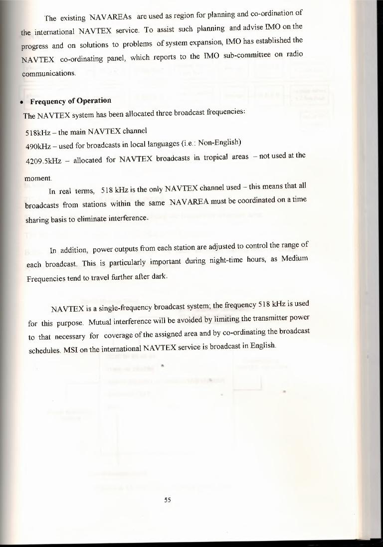
The existing NA VAREAs are used as region for planning and co-ordination of
the international NAVTEX service. To assist such planning and advise IMO on the
progress and on solutions to problems of system expansion, IMO has established the
NAVTEX co-ordinating panel, which reports to the IMO sub-committee on radio
communications.
• Frequency of Operation The NAVTEX system has been allocated three broadcast frequencies:
5 l 8kHz - the main NAVTEX channel490kHz - used for broadcasts in local languages (i.e.: Non-English)
4209.5kHz - allocated for NAVTEX broadcasts in tropical areas - not used at the
moment.In real terms, 518 kHz is the only NAVTEX channel used - this means that all
broadcasts from stations within the same NAVAREA must be coordinated on a time
sharing basis to eliminate interference.
In addition, power outputs from each station are adjusted to control the range of
each broadcast. This is particularly important during night-time hours, as Medium
Frequencies tend to travel further after dark.
NAVTEX is a single-frequency broadcast system; the frequency 518 kHz is used
for this purpose. Mutual interference will be avoided by limiting the transmitter power
to that necessary for coverage of the assigned area and by co-ordinating the broadcast
schedules. MSI on the international NAVTEX service is broadcast in English.
55
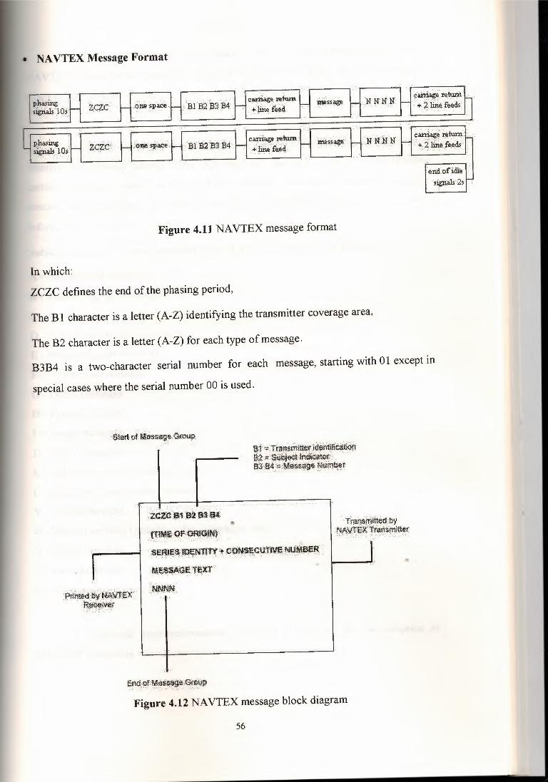
• NA VTEX Message Format
•~tc H""''i"" •ı:ıııııı~1!'ı '~.Ct' .,..,.,.. •Kl<N '~i:tt'
öııe s~ace Bfl32 B'.3 B4 c~r:r. ints~~ .N N1LN c~jt O p~ 11si¢i,ill)Ofr
i!nrl. of idle:ıjg:n;alı 2s I,;-,
Figure 4.11 NAVTEX message format
In which:
ZCZC defines the end of the phasing period,
The B 1 character is a letter (A-Z) identifying the transmitter coverage area,
The B2 character is a letter (A-Z) for each type of message.
B3B4 is a two-character serial number for each message, starting with 01 except in
special cases where the serial number 00 is used.
af ~Tra:rişmi~tıdeı:itfüt:a&m~f:;-$(i¢j~(J~cliiit~ .. ·.....BJ $4 ~r¢~~~efyıim¥t
· .. -.··~-- :- . ·. .- <·'· :- . _.· -·.: ..ZCZC 131 etB3: ij.f
.l1JMf. Qf'~9!NF. :SERJESİOENTITY~ .CöNSEbtitrvE NUMBER··••·.· .- ·.··.··.··.··.··.··.· -.-.··----· -·:. ·.· .. ··:.-··-:-.-::•:. ·.:-··-·.·.::··::::..-·:··_.-_:·····.-:··:.:: .·
· ·ME$$A$f rex.r.NNNN.
· Tra~iıfü±i~tıwNAVTfXtr~,ıirııııt~r·
p~~!)y NA'~"f:IEX.t~¢~i.ie,f
Figure 4.12 NAVTEX message block diagram
56

The transmitter identification character (BI) is a single letter allocated to each
NAVTEX shore station transmitter. NAVTEX receivers allow the operator to accept or
reject messages from any station, based on this single letter code.
The subject indicator character (B2) is also single letter code, which serves to
identify the message subject. NAVTEX receivers also allow the operator to reject
certain messages based on the subject indicator character. However, messages
concerning Navigational Warnings, Meteorological Warnings, and Search And Rescue
information can not be rejected.
Subject indicator characters assigned to the NAVTEX system are as follows:
A - Navigational warnings.
B - Meteorological warnings.
C - Ice reports.
D - Search and rescue information.
E - Meteorological forecasts.
F - Pilot service messages.
G - Decca messages.
H - Loran messages.
I - Omega messages.
J - Satnav messages.
K - Other electronic navaid messages.
L - Additional navigational messages.
V - Special services.
W - Special services (possible other languages use).
X - Special services.
Y- Special services.
Z - No message on hand (QRU).
A dedicated receiver/processor (figure 4.13) is used for the reception of
NA VTEX broadcasts.
57

58
Figure 4.13 Example ofNAVTEX receiver
4.6.3 Enhanced Group Call System
The Enhanced Group Call (EGC) (Safety NET) system, which was developed by
INMARSAT, enables the provision of unique global automated service capable of
addressing messages to pre-determined groups of ships or all vessels in both fixed and
variable geographical areas.
The system is able to meet requirements of broadcasting global, regional or local
navigational warnings, meteorological warnings and forecasts and shore-to-ship distress
alerts to any region within INMARSAT satellite coverage. In addition to coverage the
mid-ocean areas, the safety NET system can also provide an automated service in
coastal waters where it may not be feasible to establish the NAVTEX service or where
shipping density is too low to warrant its implementation.
A particularly useful feature is the ability to direct a call to a given geographical
area. The area may be fixed, as in the case of a NAV AREA or weather forecast area, or
it may be uniquely defined. This is useful for messages, such as a local storm warning
or a shore-to-ship distress alert, for which it is inappropriate to alert all ships in the
satellite coverage area.
Safety NET messages originate from registered information providers anywhere
the wor\d and are broadcast to the appropriate ocean region via a CES. Messages are
mitted bv the CES according to their 9riorit~, e.g. distress, urg,ern:.~, 1:,afot~ an.d
me.
A board ship, safety NET messages will be received either via a dedicated
'\\4.
\category, aural and visual\alarms are ,
. «; 1tl8~
receiver or via an optional receiver integrated in INMARSAT SES equipment. Upon
reception of messages of distress or urgency
activated and they can only be reset manually.
IMO has established an international safety NET co-ordinating panel for the
purpose of co-ordinating the development and the use of the international safety NET
system for promulgating MSI.
59
CHAPTER FIVE
GMDSS REQUIREMENT AND PROCEDURES WORK
5.1 GMDSS Equipment Carriage Requirements All the ships, to which the 1974 SOLAS convention, as amended in 1988,
applies, are required to carry the GMDSS radio equipment, depending on the sea areas
in which they operate.
One of two basic principles on which the GMDSS carriage requirement is based
ıs a functional requirement to answer the capability of transmitting ship-to-shore
distress alerts by at least two separate and independent means. The capability of
performing other communications functions is also required.
Carriage requirements for GMDSS radio equipment can be summarized as
follows:• Sea area Al ships will carry VHF equipment and either a satellite EPIRB or a VHF
EPIRB;
• Sea area A2 ships will carry VHF and MF equipment and a satellite EPIRB;
• Sea area A3 ships will carry VHF, MF and satellite EPIRB and either HF or satellite
communication equipment;
• Sea area A4 ships will carry VHF, MF and HF equipment and satellite EPIRB; and
• All ships will carry equipment for receiving MSI broadcasts.
The 1974 SOLAS convention, is amended in 1988, sets out the time frame for
installing the GMDSS radio equipment, taking in to account system amortization,
operational continuity, personal training, etc. to this and, the following transitional
approach for the implementation of the GMDSS is given:
60

• All ships constructed after 1 February 1992 to be fitted with a radar transponder and
two-way VHF radar telephone apparatus for survival craft;
• All ships to be fitted a NAVTEX receiver and a satellite EPIRB by 1 August 1993;
• All ships constructed before 1 February 1992 to be fitted with a radar transponder
and two-way VHF radar telephones apparatus for survival craft by 1 February 1995;
• All ships constructed after 1 February 1995 to comply with all the appropriate
requirements for the G1\1DSS;
• All ships to be fitted with at least one radar capably of operating in the 9 GHz band
by 1 February 1995; and
• All ships to comply with the appropriate requirements for the G1\1DSS by 1 February1999.
Ships which are not required to comply with the 1974 SOLAS convention are
recommended to comply with the guide lines for the participation of non-conventionships in the G1\1DSS.
Amendments to the following instruments are under consideration by IMO for
their compatibility with the G1\1DSS:
• Torremolions international convention for the safety of fishing vessels 1977;
• Code for the construction and equipment of mobile off shore drilling units;
• Code of safety dynamically supported craft;
• FAO/ILO/IMO code of safety for fisher men and fishing vessels; and
• FAO/ILO/IMO voluntary guide lines for the design, construction and equipment of
small fishing vessels.
61

• Power Supply Requirements
GMDSS equipment is required to be powered from three sources of supply:
Ship's normal alternators/generators;
Ship's emergency alternator/generator (if fitted); and
A dedicated radio battery supply.
62
The batteries are required to have a capacity to power the equipment for 1 hour
on ships with an emergency generator, and 6 hours on ships not fitted with an
emergency generator.
The batteries must be charged by an automatic charger, which is also required to
be powered from the main and emergency generators.
Changeover from AC to battery supply must be automatic and effected in such a
way that any data held by the equipment is not corrupted (i.e. "no break").
5.2 How do GMDSS Radio Procedures Work? The difference between current procedures and GMDSS is that DSC is used to
transmit the initial call. For example, currently you would initiate the call on Channel
16 to agree a working channel, whereas the GMDSS procedure would send a DSC call
on Channel 70 containing the proposed voice-working channel. Once the other station
has accepted the call then it can respond directly on the working channel.
If you are in distress, a DSC Distress Alert should be sent before the MAYDAY~procedure. This Distress Alert will activate all alarms in any DSC radios within range
and alert any radio operators to listen on the distress working channel (i.e. for VHF -
Channel 16) for the subsequent MAYDAY call. The DSC alert contains your
identification number and should contain a valid position (preferably as an automatic
input from your navigation receive.
5.3 Shore-Based SAR Communication Network and Operation
To exploit the full advantages of globally integrated satellite and terrestrial
communications, the GMDSS necessitates the establishment of an efficient
communication network between RCCs. This will consist of interconnecting links
between RCCs in accordance with arrangements made by IMO in support of the 1979
SAR Convention. In addition, each RCC will need rapid and effective communication
links with its associated coast stations, INMARSAT CESs and COSPAS-SARSAT
MCCs.
The interconnecting links between RCCs will usually be implemented using the
public switched networks or dedicated circuits. Some RCCs, particularly those not
having sufficient to access to the public switched networks, may use an INMARSAT
SES to assist in the rapid exchange of distress and safety information between RCCs.
The communications network for the future system and associated SAR
procedures will be flexible enough to satisfy many levels of international SAR co
ordination from the ideal of ocean areas where a SAR plan is operational, through many
variations in the designation of Search and Rescue Regions (SRR) and provision of
SAR facilities, to the worst cases where no responsibility has been assumed for, nor
facilities provided in, a specific area.
SAR action in response to any distress situation will be achieved through co
operation among SAR administrations, which are able to provide assistance.
The shore station nearest to the•. reported distress position should, whenever
possible, acknowledge the alert. Other shore stations receiving the alert should
acknowledge it if the nearest station does not appear to respond. The shore station,.which acknowledges the alert, must establish and maintain communications with the
ship in distress until relieved of this duty.
The first RCC, which is the RCC affiliated with the shore station which first
acknowledged the alert, should assume responsibility for all subsequent co-ordination of
63

SAR measures unless and until that responsibility is accepted by another RCC which is
in a better position to assist.
If it is not at once clear which RCC has become the first RCC because more than
one shore station has acknowledged the alert, the RCCs concerned should, as soon as
possible, agree which is to become the first RCC so that the incident is responded to
promptly. Follow-up action by the first RCC to co-ordinate SAR activities or to refer
action to a more suitable RCC should also be carried out promptly.
A flow-chart for communications and procedures illustrating the action to be
taken by the first RCC, is given in figure 5. 1.
64

e-------
zo
zo
~oıız
o zo
65
CHAPTER SIX
FLAWS IN THE SYSTEM
Despite what some would have you believe the GMDSS is NOT a perfect system.The system suffers from a number of flaws, all of which have the potential to
seriously undermine maritime safety.
The problems (and their possible solutions) are discussed below and in the following 2
sections.
6.1 Two Maritime Distress Systems The GMDSS was introduced worldwide on Feb 1, 1999.
To date, there are no facilities in many areas of the world, including many South
Pacific nations. In addition, the majority of vessels operating through many areas are
not GMDSS,equipped.
It can be argued that the GMDSS is a system primarily designed for developed
nations, with no real thought given to the needs of the developing world.GMDSS implementation by many Flag States is less than satisfactory - some ships,
particularly those registered under Flags of Convenience, are operating under
exemptions, in direct breach of the SOLAS Convention.
Whilst the theory of one universal global maritime communications system is
sound, the implementation of the system has been less than successful. For example,..Flag States are left to determine · their own requirements for vessels not covered by
SOLAS - i.e.: those engaged on domestic voyages, and those vessels under 300 GRT,
engaged on an international voyage.
Whilst this solution presents no real problems for Europe, with its multitude of
coast stations, and predominantly short voyages, it is next to useless for the vast
expanses of the Pacific and Indian Oceans, where voyages of thousands of miles are
undertaken by quite small vessels.
66

The result is that, in many parts of the world, there are two separate maritime
safety communication systems running in parallel.
Some nations are even maintaining their Morse code services on 500 kHz.
Whilst IMO have extended the requirement for merchant vessels to maintain
channel 16 VHF watch keeping until 2005, they have not continued the medium range
compatibility provisions that existed between GMDSS and non-GMDSS vessels on 2
MHz under the pre-GMDSS system.
What this means is that there are no direct communications available between
GMDSS and non-GMDSS vessels outside of VHF range (about 20 nautical miles).
A merchant ship can therefore sail by a small vessel in distress, and vice-versa.
The GMDSS pundits would have us believe that the shore based GMDSS
infrastructure will solve this problem by relaying ship-shore alerts from GMDSS vessels
to their non-equipped counterparts.
Again, this is fine in theory for Europe, but what if there is no GMDSS
compatible shore infrastructure in place?
How are the alerts to be received, and then re-broadcast on non-GMDSS systems?
Alerts go unheard, and people die.
The problem is exacerbated by the separation of commercial and distress/safety
functions brought about by the GMDSS.
Under the pre-GMDSS Morse and Radiotelephone systems, the distress and..safety services provided by Coast Radio Stations were subsidized to a certain extent by
revenue from commercial traffic (i.e.: telegrams and telephone calls).
The GMDSS has transferred the great majority of the world's maritime
commercial traffic to INMARSAT (satellite) systems.
67
Accordingly, many Coast Radio Stations are now forced to rely directly on
funding from their Governments and SAR agencies. Unfortunately, some developing
countries have precious little revenue to allocate to Coast Radio Networks.
Even Coast Stations in developed countries are feeling the effects of the
GMDSS --many of the world's major Coast Radio Stations have closed or severely
rationalized their services.
Some countries are now providing SAR-related services only from their stations.
What is being done?
To their credit, the IMO and the ITU are acting on the problem of GMDSS shore
infrastructure in developing nations.
The IMO are developing a regional SAR fund to assist in the development of
GMDSS shore stations, and the ITU have sent technical experts to many regions to
design GMDSS facilities.
Unfortunately, these initiatives may not come into effect for some time.
6.2 The False Alert Problem
• The DSC mess The GMDSS DSC system, particularly on HF, is plagued by an appallingly high
false alert rate - in excess of 99.5%.
Of the 1200 DSC alerts received hy Australian Coast Radio Stations in 1998/9,
only 2 were genuine.
This situation has reached critical levels, to the point that there is talk of
discontinuing DSC.
The root of the problem is that there is no real central operational and
administrative authority to oversee the DSC system - the operation of DSC systems on
vessels is effectively managed/regulated by individual Flag States.
68
The INMARSAT system used to suffer from a false alert rate approaching that
of DSC - INMARSAT instituted a strong and well managed program to combat the
problem, with the result that the INMARSAT false alert rate has dropped to negligible
levels.
69
The situation has reached the point that DSC has become an impediment to safety at
sea.
• Equipment complexity
Much of the DSC equipment available today is far too complex to operate.
In addition, the operating routines vary significantly from brand to brand, such that a
user trained on one type of equipment will have considerable difficulty operating
another.
DSC controller operation is complicated by the inclusion of many (unnecessary)
commercial functions - DSC controllers can be used to make automatic telephone calls
via suitably equipped HF Coast Stations. Unfortunately, there are very few, if any,
Coast Stations that offer this service.
Many controllers are equipped with small display screens - this makes operation
very difficult. There was a move some time ago at IMO* to mandate a minimum DSC
display screen size of 4 lines by 64 characters per line.
This recommendation was modified to require that a minimum of 160 characters
be displayed in two or more lines. These modifications have taken effect for all new
equipment fitted to ships as from 1 January 2000.
The modifications also mandate connection of a GPS and also the provision of
an alarm to indicate that no position data is received from the GPS or, in the case of
manual input, the position information is over 4 hours old. Any position information not
updated for more than 231/ı hours is also required to be erased from the system.
A complete copy of the new IMO requirements may be viewed here, or
downloaded here in doc format.
There is nothing in the IMO performance standards to prevent manufacturers
usıng a Personal Computer type system for DSC, i.e.: one with a large display screen -
however none have been produced, probably because of cost.
However, all is not lost - some manufacturers are producing simple to use DSC
systems, with large display screens.
It is hoped that this trend will spread.
• False alerts Equipment complexity is leading to an unprecedented number of false alerts
being transmitted.
The majority of these are caused by human error, however some have been
known to be deliberately sent out of ignorance by system installers - they program in a
bogus MMSI, and just push the distress button to see if the system works.
Such alerts are relatively easy to spot - the position is often suspect (12.34s
123.45e, for example), and the MMSI is often equally dubious (123456789, 111111111,
222222222, etc).
Can the system be too effective?
HF DSC' s effectiveness and worldwide range is leading to its downfall.
Alerts are often received from stations quite literally on the other side of the
world. It is not uncommon to receive a 12 MHz DSC alert from the North Sea in the
South Pacific.
Whilst this is quite interesting from a technical perspective, it is a complete
waste of time from a SAR viewpoint.
Compare the DSC system with INMARSAT - with INMARSAT, alerts are
directed straight to the RCC - surrounding ships are only alerted via a carefully
controlled re-broadcast from the RCC.
70

Although HF DSC is designed for ship-shore alerting, it operates in a broadcast
mode - all ships monitoring the frequency receive the call, and all are therefore able to
relay it.
• Users are too enthusiastic. The ITU operational guidelines for HF DSC require that, basically, a vessel
receiving a HF DSC alert is to immediately set watch on the corresponding R/T or
NBDP channel for the band in which the DSC alert was received and await
communications from the vessel in distress.
However, this is not happening - vessels are relaying HF DSC alerts
indiscriminately.
Ironically, the original distress alert being relayed is, in itself, probably false.
This is leading to serious congestion of the DSC channels - to the point that the original
alert has become so corrupted that it appears a Coast Station is in distress!
Unfortunately, DSC is becoming an end in itself, rather than a simple alerting
mechanism.
Many ships fail to adequately consider the information in a received alert before
relaying - an alert from a ship with an obviously false MMSI (such as 123456789)
should not be relayed.
Perusal of the international MID list .reveals that the following MID numbers are not
allocated:
000 123 111 222 333 444 777 888 999
It is very difficult for a ship's operator to change his/her DSC system's MMSI at
sea, so one can safety assume that MMSI's with the above MID's must be bogus.
Users receiving a DSC distress alert from a vessel with a MMSI starting with
any of these MID's can therefore IGNQRE the alert - it can not be genuine.
71

Misplaced enthusiasm does not stop at the shoreline either. ... Many Coast Radio
Stations are also guilty of jumping in too quickly and relaying or acknowledging alerts
that are clearly out of their area.
6.3 Solutions Solutions
So, how do we come to terms with the HF DSC fiasco?
A lot of the problem can be overcome by ships directing relays to specific coast
stations, and by Coast Stations using the geographic addressing capability of the system.
A ship receiving a HF DSC alert must:
1. WAiT and LISTEN on the corresponding radiotelephone or NBDP channel in the
band in which the DSC alert was received.
2. If no communications can be heard from the ship in distress, and/or the ship in
distress continues to send alerts, then the alert should be relayed to the nearest Coast
Station - NOT TO ALL SHIPS.
Coast stations receiving a HF DSC alert out of their area must wait for a closer
station to respond, rather than jumping in first.
DSC distress alert relays from Coast Stations should be addressed to a
Geographic area around the distressed vessel's position, in the same way as an
INMARSAT EGC message, not just broadcast to all ships.
Further, Coast Stations receiving a DSC alert from a bogus MMSI should not
relay the alert, only acknowledge it to stop the offending equipment from sending any
more.
(DSC distress acknowledgment messages automatically terminate the
transmission of DSC distress alerts).
72

These simple steps will go a long way to improving the current chaotic situationwith HF DSC.
The Th10 has finally released DSC flow charts to serve as a simple guide for
shipboard users. A link to these charts may be found at the bottom of the DSC page.
Whilst the charts are not as clear and simple as they might be, at least they are astep in the right direction.
73
CONCLUSION
The GMDSS is a system put in place internationally to enable rapid alerting of a
marine distress situation to take place. This in tum enables search and rescue proceedings
to be implemented with the minimum of time lost. The system involves the use of one or
more methods of communication including Digital Selective Calling (DSC), Emergency
Position Indicating Radio Beacons (EPIRBS), Search and Rescue Transponders (SARTS)
as well as voice radiotelephone and INMARSAT communications.
From the 1st February 1999, GMDSS was fully implemented. From this date also
the MF/HF radiotelegraphy (Morse code) service in Australia came to an end after 87 years
ofvaluable and dedicated service.
Maritime Communications Stations operate on the HF GMDSS frequencies and
broadcast weather reports and navigational warnings at scheduled times.
The basic concept of the GMDSS is that search and rescue authorities ashore, as
well as shipping in the immediate vicinity of the ship, or persons, in distress, will be rapidly
alerted to a distress incident so they can assist in a co-ordinated search and rescue operation
with the minimum delay.
The system also provides for urgency and safety communications and the
promulgation of maritime safety information (navigational and meteorological warnings
and forecasts and other urgent safety information).
In other words, every ship is able, irrespective of the area in which it operates, to perform
those communication functions, which are essential for the safety of the ship it self and of
other ships operating in the same area.
74
REFERENCES
[ 1] GMDSS Hand Book Part One and Part Two, International Maritime Organization(ThfO), 1997.
"-[2] Sue Fletcher ,Reeds VHF DSC Handbook, Thomas Reed, 1997.
[3] ENG. Abed Alhamed Abed Alassem, GMDSS, Arab Academy For Science AndTechnology College OfMaritime Transport And Technology, 1995.
[4] Michael Gale, VHF GMDSS Handbook, Femhurst, 1998.
[5] GMDSS Concept, http://:www.gmdss.com.au.
[6] lNMARSAT system, http://coastradio.tripod.com/gmdss.htm.
75
Top Related