


Languages
Pages
Legal

International Conference on Hydrogen Safety (ICHS3) Palais des Congrès Ajaccio - FRANCE
16-18 September 2009
NATURAL AND FORCED VENTILATION STUDY IN AN ENCLOSURE HOSTING A FUEL CELL
Marco N. Carcassi, Gennaro M. Cerchiara, Martino Schiavetti, Nicola Mattei.

The purpose of the experimental work is to determine the conditions for which an enclosure can guest a fuel cell for civil use.
ATEX – Limits.
Zone 0 : Continuous leakage → 25%LEL = 1%H2vol;Zone 1 : Operational release → 25%LEL = 1%H2vol;Zone 2 : Occasional leakage → 50%LEL = 2%H2vol.
CEI EN 60079 - 10“Electrical apparatus for explosive atmospheres
Guide for classification of hazardous areas”

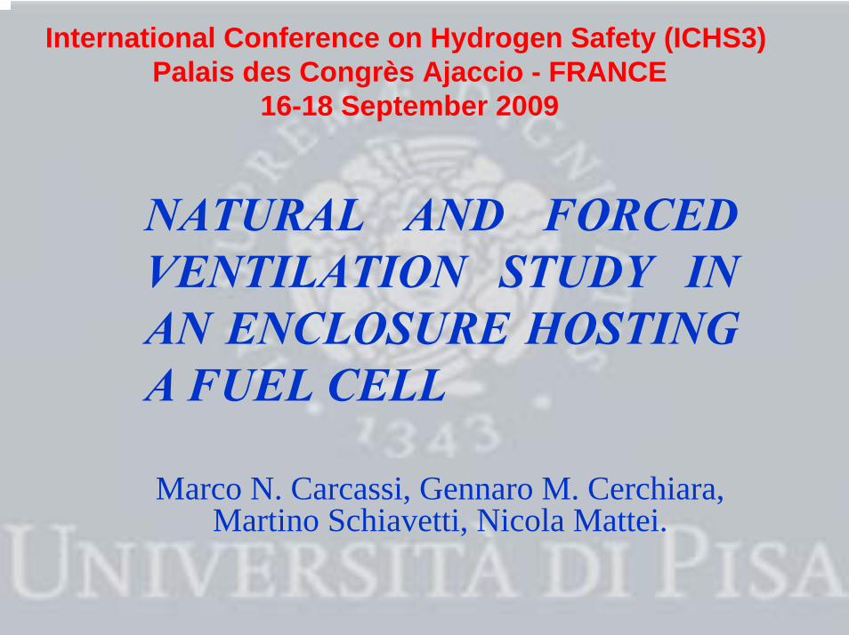
The fuel cell and the leakage monitoring system

Fuel Cell - Penta H2
PerformanceNet electric power: 1 to 5 and IdleVoltage:120 or 220 VAC
Hydrogen SupplyHydrogen Grade: Grade 5.5 (EU)Inlet pressure: 2-5 baraMass flow: Dead end - pulsingAnode stoichiometric: 1,02Fuel Consumption: 4,2 Nm3/hr at max power
Length 800 mm ; Depth 688 mmHeight 1024 mm; Weight 200 kg

Small leakage from H2 inletCEI 31 - 35 (2001 - 01) recommendation
Calculations performed by EFFECTS-SGIS 7.3.
PH2 [bar]ΦL[mm]
AL[mm2] 2 2,5 3 3,5 4 4,5 5
0,56 0.25 18,25 22,76 27,34 31,92 36,50 41,08 45,66
0,8 0.50 36,72 45,89 55,12 64,14 73,37 82,76 91,62
1.13 1.00 73,74 91,18 109,36 128,13 146,30 164,77 183,25
GH2[nl/min]
ΦL = H2 Leakage Diameter for pipelines < 150 mm the leakage Area is AL = 0.25 mm2
ΦP = 6 mm
Leakage Monitoring System

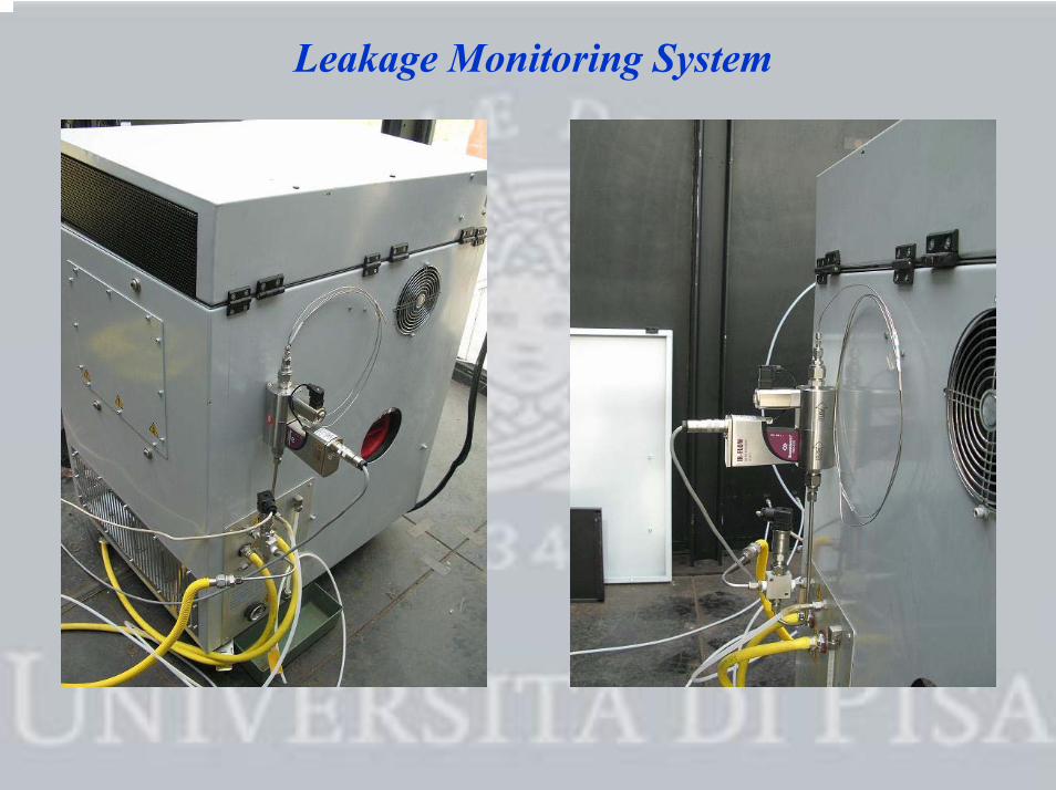
The CVE hosting the fuel cell and the vent system
Fuel cell PentaH2 installed inside CVE Particular of the Vent 1 (central)

Size and location of Vent 1(Side A) coordinates in [mm];
Vent 1 small = central rectangle AV1s = 0.35 m2;
Vent 1 big = both rectangles AV1b = 0.70 m2.
Size and location of Vent 2 and Vent 4 (Side C) coordinates in [mm]AV2 = AV4 = 0.14 m2.
AV = Vent Area [m2]
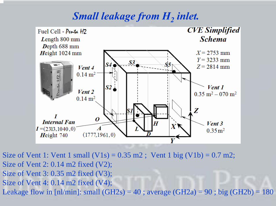
Small leakage from H2 inlet.
Size of Vent 1: Vent 1 small (V1s) = 0.35 m2 ; Vent 1 big (V1b) = 0.7 m2;Size of Vent 2: 0.14 m2 fixed (V2);Size of Vent 3: 0.35 m2 fixed (V3);Size of Vent 4: 0.14 m2 fixed (V4);Leakage flow in [nl/min]: small (GH2s) = 40 ; average (GH2a) = 90 ; big (GH2b) = 180

H2 sampling points.Five Channels - %H2vol.a) flow meters;b) sampling pipelines;c) zeolites;d) concentration measurers.

The geometry of ventilation and ATEX value of
recirculation air flow
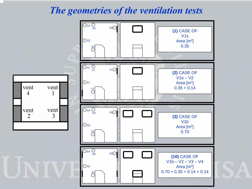
The geometries of the ventilation tests
S1
S2
S4S3 S5
(1) CASE OFV1s
Area [m2]0.35
S1
S2
S4S3 S5
(2) CASE OFV1s – V2Area [m2]
0.35 + 0.14
S1
S2
S4S3 S5
(10) CASE OFV1b – V2 – V3 – V4
Area [m2]0.70 + 0.35 + 0.14 + 0.14
S1
S2
S4S3 S5
(3) CASE OFV1b
Area [m2]0.70

ATEX Calculus of Qawvalue in all geometries(Natural Ventilation)
QAW = air flow recirculation in Natural Ventilation conditions

Natural Ventilation Test results
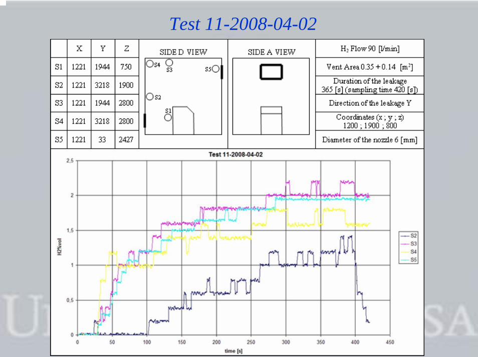
Test 11-2008-04-02

Test 12-2008-04-02H2 Flow [l/min] 90
Vent Area [m2] 0.70 + 0.14
Duration of the leakage [s] 373
Direction of the leakage -Y
Coordinates (x ; y ; z) 1200 ; 1900 ; 800
Diameter of the nozzle [mm] 6S1
S2
S4S3 S5

Empirical model for the calculus of the venting area

Natural Ventilation Model steps.
To set the ventilation system we need:
NV Geometry KV QAW AV

Calculus of KV
In Steady State Conditions
During the initial steps of the tests the enclosure volume with homogenous H2 concentration is a fraction KV of the whole internal volume.
H2(P)%vol and QH2 are measured during the experiments
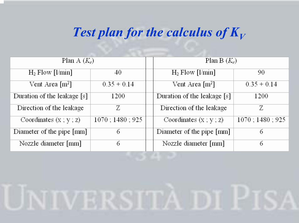
Test plan for the calculus of KV
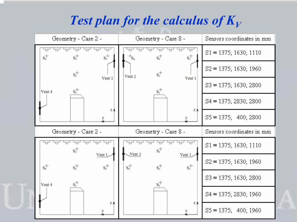
Test plan for the calculus of KV

Forced Ventilation Tests and results

Forced Ventilation Tests
Fan Model AX rpm Power
[kW]Voltage
[V]
current intensity
[A]
Diameter[mm]
Air – flow[m3/s]
Coordinates fan centre[x; y; z]
Fan 1 (1375; 0; 2670)254T 1500 0,04 220/380 0,25 260 0.33
Fan 2 (1375; 3220;2670)

Conclusions

Conclusions
Where it is possible, it is convenient to use one or more suitable solutions like:
-To reasonably increase the vent areas beyond the minimum value ;-To consider the vent areas for a leak flow reasonably bigger then the minimum; -To incline the roof making the NV easy and efficient;-To install a small fan able to remove the internal mixture from the enclosure.
The limit of 40 l/min of the leakage is relevant for every kind of fuel cell suitable for civil use. leaks beyond 90 l/min would refer to catastrophic leakage and therefore should not be considered with the assumptions made.

THANK YOU
Marco N. Carcassi, Gennaro M. Cerchiara, Martino Schiavetti, Nicola Mattei.
Top Related