


Languages
Pages
Legal


TM
Since 1985 » Simple. Predictable. Profitable.
Narrow Implant Catalog
™
IMPLANTSNARROW
™
Bicon implants, abutments, instrumentation, and components are engineered, manufactured, packaged, and/or sterilized at ISO Certified facilities.
Bicon fulfills the stringent requirements of the European Directive 93/42/EEC for medical devices as well as strict adherence to the ISO 13485 standard.
Copyright © 2010 Bicon LIT-004 R0610
Bicon offers a full complement of implants and restorative options to meet all clinical needs of an implant practice. In order to assist our clinicians, Bicon has created this catalog depicting our line of Narrow Implants.
The Bicon design is driven by simplicity. A cornerstone of its simplicity is narrow implants. The Bicon system has had 3.5mm implants since 1985. These narrow implants facilitate the restoration of missing maxillary lateral incisors as well as individual mandibular incisors. The sloping shoulder of the Bicon implant enhances crestal bone preservation while providing space for the interdental papillae — offering the opportunity for natural-looking gingival aesthetics.
The products contained in this manual represent those products which Bicon clinicians primarily use for narrow ridges where wider implants are unable to be placed. If a clinical situation arises in which other sizes of implants are required or if a different style of an abutment is needed, please refer to Bicon’s Complete Catalog or visit www.bicon.com to view our entire product line.

THE BICON SYSTEM A simple and elegant design with platform switching that
has remained unchanged and in continuous use since 1985.
3.5mmor 4.0mmImplant
3.0mm Well2.5mm Well2.0mm Well
www.bicon.com1
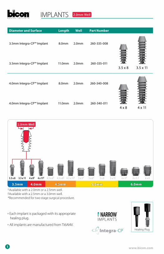
IMPLANTS 2.0mm Well
Diameter and Surface Length Well Part Number
3.5mm Integra-CP™ Implant 8.0mm 2.0mm 260-335-008
3.5 x 8 3.5 x 113.5mm Integra-CP™ Implant 11.0mm 2.0mm 260-335-011
4.0mm Integra-CP™ Implant 8.0mm 2.0mm 260-340-008
4 x 8 4 x 114.0mm Integra-CP™ Implant 11.0mm 2.0mm 260-340-011
3.5mm 4.0mm 4.5mm 5.0mm 6.0mm
3.5 x 113.5 x 8 4 x 11‡4 x 8‡ 6 x 84.5 x 11∆4.5 x 8∆ 5 x 8 5 x 11 6 x 5.7 6 x 5*5 x 6* 5 x 5*4.5 x 6*
‡ Available with a 2.0mm or a 2.5mm well.∆Available with a 2.5mm or a 3.0mm well.
**Recommended for two stage surgical procedure.
■ Each implant is packaged with its appropriate healing plug.
■ All implants are manufactured from Ti6Al4V.Healing Plug
™
IMPLANTSNARROW
™
Integra-CP™™
2
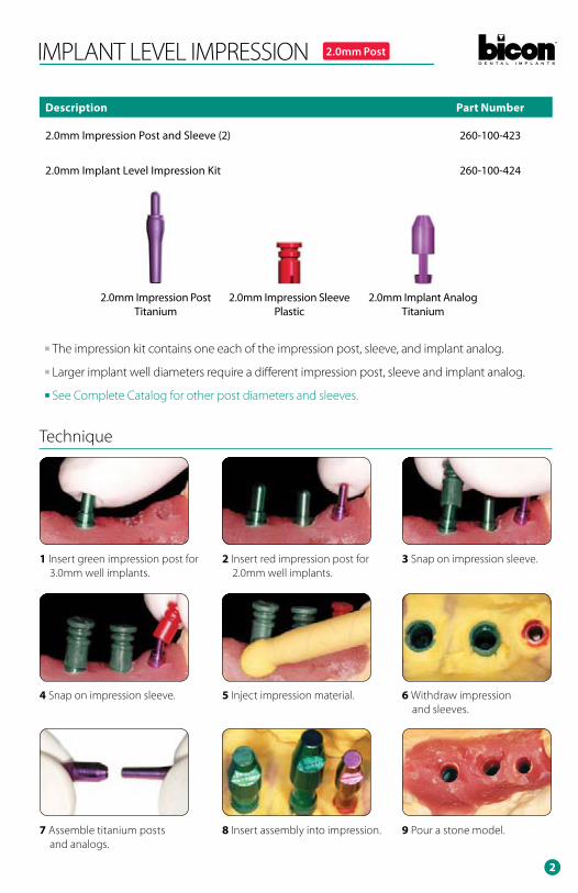
1 Insert green impression post for 3.0mm well implants.
2 Insert red impression post for 2.0mm well implants.
3 Snap on impression sleeve.
4 Snap on impression sleeve. 5 Inject impression material. 6 Withdraw impression and sleeves.
7 Assemble titanium posts and analogs.
8 Insert assembly into impression. 9 Pour a stone model.
IMPLANT LEVEL IMPRESSION 2.0mm Post
Description Part Number
2.0mm Impression Post and Sleeve (2) 260-100-423
2.0mm Implant Level Impression Kit 260-100-424
■ The impression kit contains one each of the impression post, sleeve, and implant analog.
■ Larger implant well diameters require a different impression post, sleeve and implant analog.
■ See Complete Catalog for other post diameters and sleeves.
2.0mm Impression PostTitanium
2.0mm Impression SleevePlastic
2.0mm Implant AnalogTitanium
Technique

www.bicon.com3
NON-SHOULDERED ABUTMENTS 2.0mm Post
Description Diameter Height Angle Post Part Number
4.0 x 6.5mm 0˚ Abutment
4.0mm 6.5mm 0˚ 2.0mm 260-140-002
0˚ 15˚4.0 x 6.5mm 15˚ Abutmen
4.0mm 6.5mm 15˚ 2.0mm 260-140-015
5.0 x 6.5mm 0˚ Abutment
5.0mm 6.5mm 0˚ 2.0mm 260-150-001
0˚ 15˚5.0 x 6.5mm 15˚ Abutment
5.0mm 6.5mm 15˚ 2.0mm 260-150-015
■ For additional abutment sizes see page 15–16.
■ The non-shouldered abutments are designed for PFM restorations and are useful for the IAC restorations.
■ Non-shouldered abutments are fully “preppable” and may be modified intra-orally or extra-orally.
■ Clinicians may make direct impressions of non-shouldered abutments or make indirect impressions with the use of an impression sleeve.
■ See Complete Catalog for information on emergence cuffs, impression sleeves, and transfer dies that are available.
4
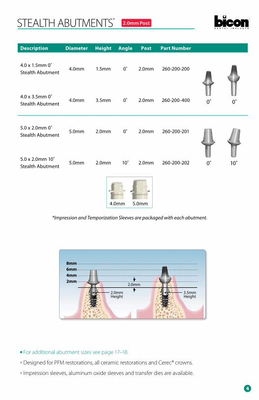
STEALTH ABUTMENTS* 2.0mm Post NON-SHOULDERED ABUTMENTS
Description Diameter Height Angle Post Part Number
4.0 x 1.5mm 0˚ Stealth Abutment
4.0mm 1.5mm 0˚ 2.0mm 260-200-200
0˚ 0˚4.0 x 3.5mm 0˚ Stealth Abutment
4.0mm 3.5mm 0˚ 2.0mm 260-200-400
5.0 x 2.0mm 0˚ Stealth Abutment
5.0mm 2.0mm 0˚ 2.0mm 260-200-201
0˚ 10˚5.0 x 2.0mm 10˚ Stealth Abutment
5.0mm 2.0mm 10˚ 2.0mm 260-200-202
■ For additional abutment sizes see page 17–18.
■ Designed for PFM restorations, all ceramic restorations and Cerec® crowns.
■ Impression sleeves, aluminum oxide sleeves and transfer dies are available.
2mm4mm6mm8mm
2.0mm
2.0mm Height
3.5mm Height
4.0mm 5.0mm
*Impression and Temporization Sleeves are packaged with each abutment.
www.bicon.com5
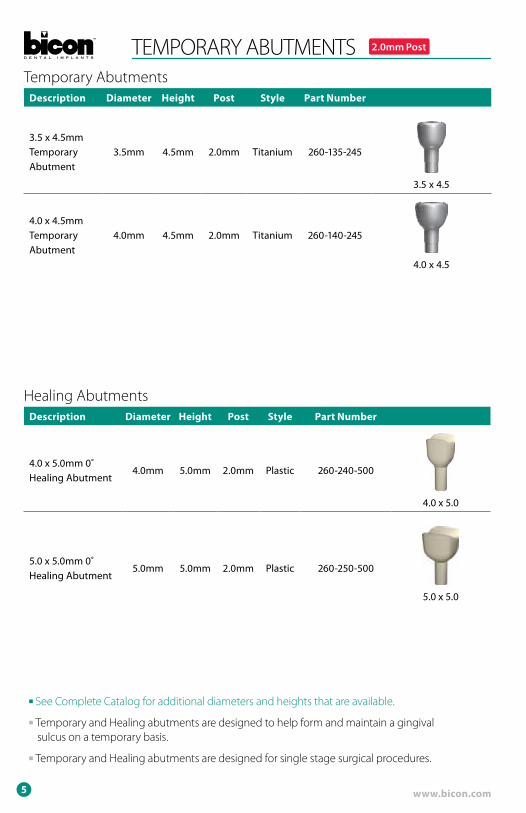
Description Diameter Height Post Style Part Number
4.0 x 5.0mm 0˚ Healing Abutment
4.0mm 5.0mm 2.0mm Plastic 260-240-500
4.0 x 5.0
5.0 x 5.0mm 0˚ Healing Abutment
5.0mm 5.0mm 2.0mm Plastic 260-250-500
5.0 x 5.0
Healing Abutments
TEMPORARY ABUTMENTS 2.0mm Post
Description Diameter Height Post Style Part Number
3.5 x 4.5mm Temporary Abutment
3.5mm 4.5mm 2.0mm Titanium 260-135-245
3.5 x 4.5
4.0 x 4.5mm Temporary Abutment
4.0mm 4.5mm 2.0mm Titanium 260-140-245
4.0 x 4.5
Temporary Abutments
■ See Complete Catalog for additional diameters and heights that are available.
■ Temporary and Healing abutments are designed to help form and maintain a gingival sulcus on a temporary basis.
■ Temporary and Healing abutments are designed for single stage surgical procedures.

6
Description Height Angle Post Part Number
2.0mm 0˚ Brevis Abutment 2.0mm 0˚ 2.0mm 260-100-404
0˚ 15˚2.0mm 15˚ Brevis Abutment 2.0mm 15˚ 2.0mm 260-100-405
4.0mm 0˚ Brevis Abutment 4.0mm 0˚ 2.0mm 260-100-406
0˚ 15˚4.0mm 15˚ Brevis Abutment 4.0mm 15˚ 2.0mm 260-100-407
*Each abutment is packaged with a titanium housing and o-ring.
Description Part Number
Brevis Abutment Chairside Kit 260-100-212
Rubber O-Ring Brevis Housing
Brevis Impression Kit without Housing 260-100-218
Impression Cap Aluminum Transfer Die
Restorative Components
2.0mm
3.0mm 3.0mm
4.0mm
3.0mm
6.0mm
Measurement Guide
■ See Complete Catalog for additional abutment heights that are available.
BREVIS™ ABUTMENTS* 2.0mm Post

www.bicon.com7
BICON SURGICAL KIT
Description Part Number
Comprehensive Surgical Kit 260-101-098
Surgical Mallet
Silicone Dappen Dish
Healing Plug Cutter
8
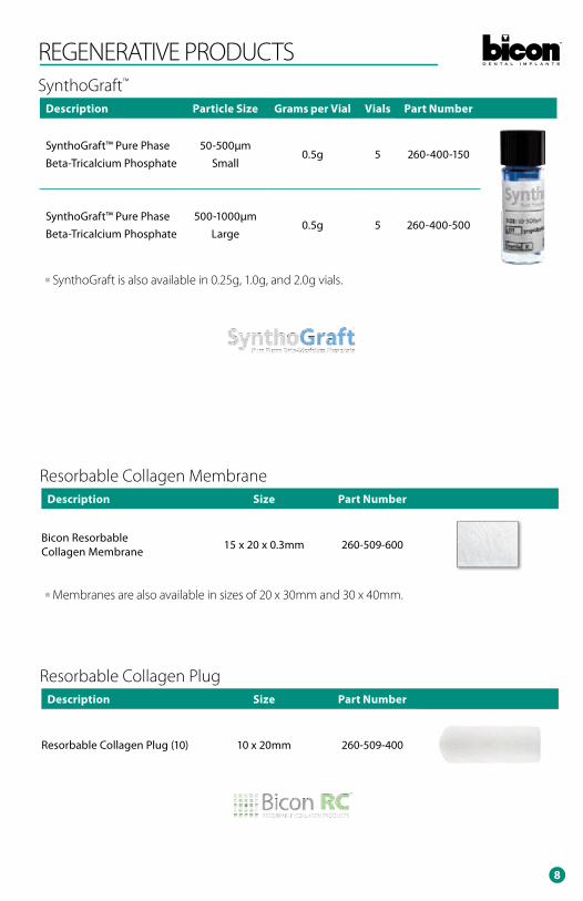
REGENERATIVE PRODUCTS
Description Particle Size Grams per Vial Vials Part Number
SynthoGraft™ Pure Phase Beta-Tricalcium Phosphate
50-500µmSmall
0.5g 5 260-400-150
SynthoGraft™ Pure Phase Beta-Tricalcium Phosphate
500-1000µmLarge
0.5g 5 260-400-500
SynthoGraft™
Description Size Part Number
Bicon Resorbable Collagen Membrane 15 x 20 x 0.3mm 260-509-600
Resorbable Collagen Membrane
Description Size Part Number
Resorbable Collagen Plug (10) 10 x 20mm 260-509-400
Resorbable Collagen Plug
■ SynthoGraft is also available in 0.25g, 1.0g, and 2.0g vials.
■ Membranes are also available in sizes of 20 x 30mm and 30 x 40mm.

www.bicon.com9
Seat implant by tapping gently on healing plug or directly into the implant well with an appropriate seating tip.
10
Cut healing plug. Ensure that no sharp edges remain that could irritate soft tissue.
11
Place harvested bone graft over shoulder of implant. See Step #6 above.
12
Close and wait a minimum of ten to twelve weeks for osseointegration.
13
Place an abutment with a 2.0mm post into pilot hole and confirm appropriateness with a vacu-press template.
Widen socket with sequentially larger reamers without irrigation at a maximum of 50 RPM. In this case, a 4.0 x 8.0mm implant has been chosen so the final bur used also has a diameter of 4.0mm.
Place harvested autogenous bone, intermittently removed from the flutes of the reamer burs, into a silicone dappen dish for later use.
4
4.0
54.0
6
The implant’s sterile blister pack is dropped onto a sterile tray prior to removing its Tyvek® backing before the implant’s inner packaging is cut with a pair of scissors.
Remove implant from poly bag.Harvest bone debris from reamer flutes and socket.
7 8 9
TWO STAGE SURGICAL TECHNIQUETwo Stage Surgery Implant Insertion Technique
Use paralleling pins to facilitate alignment when placing multiple implants.
3
For the best emergence, drill a 2.0mm pilot hole (with external irrigation) 2.0mm deeper than the chosen implant length when adequate bone height is available.
2
Extraction Site Envelope Scalloped
1 FLAP DESIGNS
10
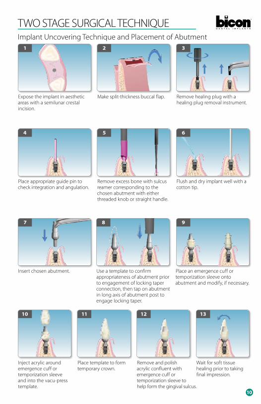
TWO STAGE SURGICAL TECHNIQUEImplant Uncovering Technique and Placement of Abutment
Inject acrylic around emergence cuff or temporization sleeve and into the vacu-press template.
10
Place template to form temporary crown.
11
Remove and polish acrylic confluent with emergence cuff or temporization sleeve to help form the gingival sulcus.
12
Wait for soft tissue healing prior to taking final impression.
13
Expose the implant in aesthetic areas with a semilunar crestal incision.
1
Remove healing plug with a healing plug removal instrument.
3
Make split-thickness buccal flap.
2
Place appropriate guide pin to check integration and angulation.
4
Flush and dry implant well with a cotton tip.
6
Remove excess bone with sulcus reamer corresponding to the chosen abutment with either threaded knob or straight handle.
5
Insert chosen abutment.
7
Use a template to confirm appropriateness of abutment prior to engagement of locking taper connection, then tap on abutment in long axis of abutment post to engage locking taper.
8
Place an emergence cuff or temporization sleeve onto abutment and modify, if necessary.
9

www.bicon.com11
NON-SHOULDERED ABUTMENT RESTORATIONSPorcelain Fused to Metal and Integrated Abutment Crown™
PFM PFM / IAC
NON-SHOULDERED ABUTMENT
Method of Impression
Direct Abutment Level
Indirect Abutment Level
Implant Level
Impression Product Needed None
Impression Sleeve for Non-Shouldered
Abutment
Implant Level Impression Kit
Temporization Product Needed
Emergence Cuff or Temporization Sleeve
for Non-Shouldered
Abutment
Temporization Sleeve for
Non-Shouldered Abutment
Temporary or Healing Abutment
and/or Transitional Crown
Laboratory Product Needed None
Abutment Transfer Die
and Waxing Sleeve for Non-Shouldered
Abutment
Non-Shoulderedor Laboraory
Abutment
FINAL CROWN
™
12
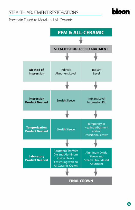
STEALTH ABUTMENT RESTORATIONSPorcelain Fused to Metal and All-Ceramic
PFM & ALL-CERAMIC
STEALTH SHOULDERED ABUTMENT
Method of Impression
Indirect Abutment Level
Implant Level
Impression Product Needed Stealth Sleeve Implant Level
Impression Kit
Temporization Product Needed Stealth Sleeve
Temporary or Healing Abutment
and/or Transitional Crown
Laboratory Product Needed
Abutment Transfer Die and Aluminum
Oxide Sleeve if restoring with an All Ceramic Crown
Aluminum Oxide Sleeve and
Stealth Shouldered Abutment
FINAL CROWN

www.bicon.com13
TEMPORIZATION OPTIONSOPTION ONE: TRANSITIONAL RESTORATION WITH SLEEvE
1 Insert appropriate non-shouldered or stealth shouldered abutment. The diameter of the abutment is dictated by the anatomy of the interdental papillae. The abutment should support the papillae without encroaching upon them.
2 Tap the abutment in the long axis of the abutment post and implant well.
3 Orientate the internal flat(s) of the appropriate temporization sleeve with the external flat(s) of the abutment prior to snapping it onto the abutment.
4 Confirm the appropriateness of the temporization sleeve with a vacuum formed template. Adjust the sleeve as necessary.
5 Inject transitional crown material around the temporization sleeve.
6 Inject transitional material into the vacuum-formed template prior to re-inserting it over the temporization sleeve to form a transitional prosthesis.
7 Remove transitional prosthesis for polishing.
8 Snap the completed transitional prosthesis onto the abutment to facilitate the formation and preservation of an aesthetic soft tissue emergence profile.
OPTION TWO: TEMPORIzATION WITH A TEMPORARy OR HEALING ABuTMENT
At the time of uncovering, place a titanium temporary abutment or a plastic healing abutment. These abutments will support the soft tissue and assist in the formation of the gingival sulcus. Either abutment may be modified to achieve a desired gingival contour. Transitional crowns should not be placed on temporary or healing abutments. See Bicon catalogs for a complete listing of abutment sizes and shapes that are available.
OPTION THREE: A TRANSITIONAL PROSTHESIS IN THE AESTHETIC zONE
4.0 x 4.5 4.0 x 6.5 5.0 x 4.5 5.0 x 6.5
1 Choose appropriately sized temporary or healing abutment. See Option #2 above.
2 Insert temporary or healing abutment into the implant well and gently seat the abutment by tapping on the head of the abutment. Removal of the abutment may be achieved with a variety of extraction forceps.
3 In aesthetic areas, a flipper may be inserted for aesthetics and function while tissue is healing around the temporary abutments.
4 View of inserted provisional restoration.
14
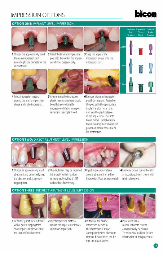
IMPRESSION OPTIONSOPTION ONE: IMPLANT LEvEL IMPRESSION
1 Choose the appropriately sized titanium impression post according to the diameter of the implant well.
2 Insert the titanium impression post into the well of the implant with finger pressure only.
3 Snap the appropriate impression sleeve onto the impression post.
4 Inject impression material around the plastic impression sleeve and make impression.
5 After making the impression, plastic impression sleeve should be withdrawn within the impression while titanium post remains in the implant well.
6 Remove titanium impression post from implant. Assemble the post with the appropriate implant analog. Insert this unit into the plastic sleeve in the impression. Pour soft tissue model. The laboratory technician may now choose the proper abutment for a PFM or IAC restoration.
OPTION TWO: DIRECT ABuTMENT LEvEL IMPRESSION
1 Choose an appropriately sized abutment and definitively seat the abutment with a gentle tapping force.
2 The abutment may be modified intra-orally with irrigation or extra-orally with a #1557 carbide bur, if necessary.
3 Inject impression material around abutment for a direct impression. Pour a stone model.
4 Fabricate crown conventionally at laboratory. Insert crown with minimal cement.
OPTION THREE: INDIRECT ABuTMENT LEvEL IMPRESSION
1 Definitively seat the abutment with a gentle tapping force. Snap impression sleeves onto the unmodified abutment.
2 Inject impression material around the impression sleeves and make impression.
3 Withdraw the plastic impression sleeves in the impression. Choose appropriately sized aluminum transfer die and insert the die into the plastic sleeve.
4 Pour a soft tissue model. Fabricate crowns conventionally. See Bicon Technique Manuals for further information on this procedure.
Impression Post
Titanium
Impression SleevePlastic
Implant Analog
Titanium
2.0mm
2.5mm
3.0mm

www.bicon.com15
NON-SHOULDERED ABUTMENT
3.5mm Diameter 4.0mm Diameter 5.0mm Diameter 6.5mm Diameter 7.5mm Diameter
0˚ 15˚ 0˚ 15˚ 25˚ 0˚ 15˚ 0˚ 15˚ 0˚ 15˚ 25˚ 0˚ 15˚ 0˚ 15˚ 0˚ 15˚ 0˚ 15˚ 0˚ 15˚
3.5 x 6.5 0˚260-135-001
3.5 x 6.5 15˚260-135-015
4.0 x 6.5 0˚260-140-002
4.0 x 6.5 15˚260-140-015
4.0 x 6.5 25˚260-140-025
4.0 x 10 0˚260-140-101
4.0 x 10 15˚260-140-115
5.0 x 5.0 0˚260-150-050
5.0 x 5.0 15˚260-150-055
5.0 x 6.5 0˚260-150-001
5.0 x 6.5 15˚260-150-015
5.0 x 6.5 25˚260-150-025
5.0 x 12 0˚260-150-201
5.0 x 12 15˚260-150-215
4.0 x 6.5 0˚260-240-001
4.0 x 6.5 15˚260-240-015
4.0 x 6.5 25˚260-240-025
4.0 x 10 0˚260-240-101
4.0 x 10 15˚260-240-115
5.0 x 6.5 0˚260-250-001
5.0 x 6.5 15˚260-250-015
5.0 x 6.5 25˚260-250-025
5.0 x 10 0˚260-250-111
5.0 x 10 15˚260-250-115
6.5 x 5.0 0˚260-265-050
6.5 x 5.0 15˚260-265-055
4.0 x 6.5 0˚260-340-001
4.0 x 6.5 15˚260-340-015
4.0 x 10 0˚260-340-101
4.0 x 10 15˚260-340-115
5.0 x 5.0 0˚260-350-050
5.0 x 5.0 15˚260-350-055
5.0 x 6.5 0˚260-350-001
5.0 x 6.5 15˚260-350-015
5.0 x 6.5 25˚260-350-025
5.0 x 10 0˚260-350-101
5.0 x 10 15˚260-350-115
5.0 x 12 0˚260-350-201
5.0 x 12 15˚260-350-215
6.5 x 5.0 0˚260-365-050
6.5 x 5.0 15˚260-365-055
6.5 x 6.5 0˚260-365-001
6.5 x 6.5 15˚260-365-015
7.5 x 8.0 0˚260-375-801
7.5 x 8.0 15˚260-375-815
™
2.5mm Post
10.0
6.5
5.0
Top of Implant
10.0
mm
2.5mm
™
IMPLANTS3.0mm Post
12.0
Top of Implant
10.0
8.0
6.5
5.0
12.0
mm
2.5mm
2.0mm PostIMPLANTS
NARROW™™
12.0
10.0
6.5
5.0
Top of Implant
12.0
mm
3.0mm

16
SELECTION GUIDE
3.5mm Diameter 4.0mm Diameter 5.0mm Diameter 6.5mm Diameter 7.5mm Diameter
0˚ 15˚ 0˚ 15˚ 25˚ 0˚ 15˚ 0˚ 15˚ 0˚ 15˚ 25˚ 0˚ 15˚ 0˚ 15˚ 0˚ 15˚ 0˚ 15˚ 0˚ 15˚
3.5 x 6.5 0˚260-135-001
3.5 x 6.5 15˚260-135-015
4.0 x 6.5 0˚260-140-002
4.0 x 6.5 15˚260-140-015
4.0 x 6.5 25˚260-140-025
4.0 x 10 0˚260-140-101
4.0 x 10 15˚260-140-115
5.0 x 5.0 0˚260-150-050
5.0 x 5.0 15˚260-150-055
5.0 x 6.5 0˚260-150-001
5.0 x 6.5 15˚260-150-015
5.0 x 6.5 25˚260-150-025
5.0 x 12 0˚260-150-201
5.0 x 12 15˚260-150-215
4.0 x 6.5 0˚260-240-001
4.0 x 6.5 15˚260-240-015
4.0 x 6.5 25˚260-240-025
4.0 x 10 0˚260-240-101
4.0 x 10 15˚260-240-115
5.0 x 6.5 0˚260-250-001
5.0 x 6.5 15˚260-250-015
5.0 x 6.5 25˚260-250-025
5.0 x 10 0˚260-250-111
5.0 x 10 15˚260-250-115
6.5 x 5.0 0˚260-265-050
6.5 x 5.0 15˚260-265-055
4.0 x 6.5 0˚260-340-001
4.0 x 6.5 15˚260-340-015
4.0 x 10 0˚260-340-101
4.0 x 10 15˚260-340-115
5.0 x 5.0 0˚260-350-050
5.0 x 5.0 15˚260-350-055
5.0 x 6.5 0˚260-350-001
5.0 x 6.5 15˚260-350-015
5.0 x 6.5 25˚260-350-025
5.0 x 10 0˚260-350-101
5.0 x 10 15˚260-350-115
5.0 x 12 0˚260-350-201
5.0 x 12 15˚260-350-215
6.5 x 5.0 0˚260-365-050
6.5 x 5.0 15˚260-365-055
6.5 x 6.5 0˚260-365-001
6.5 x 6.5 15˚260-365-015
7.5 x 8.0 0˚260-375-801
7.5 x 8.0 15˚260-375-815
2.5mm Post
Top of Implant
10.0
mm
2.5mm
10.0
6.5
5.0
3.0mm Post
Top of Implant
12.0
mm
2.5mm
12.0
10.0
8.0
6.5
5.0
2.0mm Post
12.0
10.0
6.5
5.0
Top of Implant
12.0
mm
3.0mm

www.bicon.com17
STEALTH SHOULDERED ABUTMENT
3.5mm Diameter 4.0mm Diameter 5.0mm Diameter 6.5mm Diameter
0˚ 10˚ 0˚ 10˚ 0˚ 10˚ 0˚ 10˚ 0˚ 10˚ 0˚ 10˚ 0˚ 10˚ 0˚ 10˚ 0˚ 10˚ 0˚ 15˚
3.5 x 1.5 0˚ 260-200-150
4.0 x 1.5 0˚ 260-200-200
4.0 x 3.5 0˚ 260-200-400
5.0 x 2.0 0˚ 260-200-201
5.0 x 2.0 10˚ 260-200-202
5.0 x 4.0 0˚ 260-200-221
5.0 x 4.0 10˚ 260-200-222
5.0 x 6.0 0˚ 260-200-241
5.0 x 6.0 10˚ 260-200-242
4.0 x 1.5 0˚ 260-250-300
4.0 x 3.5 0˚ 260-250-400
5.0 x 2.0 0˚ 260-250-301
5.0 x 2.0 10˚ 260-250-302
5.0 x 3.0 0˚ 260-250-311
5.0 x 3.0 10˚ 260-250-312
5.0 x 4.0 0˚ 260-250-321
5.0 x 4.0 10˚ 260-250-322
5.0 x 6.0 0˚ 260-250-341
5.0 x 6.0 10˚ 260-250-342
4.0 x 1.5 0˚ 260-300-300
4.0 x 3.5 0˚ 260-300-400
5.0 x 2.0 0˚ 260-300-301
5.0 x 2.0 10˚ 260-300-302
5.0 x 3.0 0˚ 260-300-311
5.0 x 3.0 10˚ 260-300-312
5.0 x 4.0 0˚ 260-300-321
5.0 x 4.0 10˚ 260-300-322
5.0 x 6.0 0˚ 260-300-341
5.0 x 6.0 10˚ 260-300-342
5.0 x 8.0 0˚ 260-300-361
6.5 x 2.0 0˚ 260-300-601
6.5 x 4.0 0˚ 260-300-621
™
2.5mm Post
2.0mm PostIMPLANTS
NARROW™™
0.02.04.06.08.0
8.0m
m
0.02.04.06.08.0
8.0m
m
™
IMPLANTS3.0mm Post
0.02.04.06.08.0
8.0m
m

18
SELECTION GUIDE
3.5mm Diameter 4.0mm Diameter 5.0mm Diameter 6.5mm Diameter
0˚ 10˚ 0˚ 10˚ 0˚ 10˚ 0˚ 10˚ 0˚ 10˚ 0˚ 10˚ 0˚ 10˚ 0˚ 10˚ 0˚ 10˚ 0˚ 15˚
3.5 x 1.5 0˚ 260-200-150
4.0 x 1.5 0˚ 260-200-200
4.0 x 3.5 0˚ 260-200-400
5.0 x 2.0 0˚ 260-200-201
5.0 x 2.0 10˚ 260-200-202
5.0 x 4.0 0˚ 260-200-221
5.0 x 4.0 10˚ 260-200-222
5.0 x 6.0 0˚ 260-200-241
5.0 x 6.0 10˚ 260-200-242
4.0 x 1.5 0˚ 260-250-300
4.0 x 3.5 0˚ 260-250-400
5.0 x 2.0 0˚ 260-250-301
5.0 x 2.0 10˚ 260-250-302
5.0 x 3.0 0˚ 260-250-311
5.0 x 3.0 10˚ 260-250-312
5.0 x 4.0 0˚ 260-250-321
5.0 x 4.0 10˚ 260-250-322
5.0 x 6.0 0˚ 260-250-341
5.0 x 6.0 10˚ 260-250-342
4.0 x 1.5 0˚ 260-300-300
4.0 x 3.5 0˚ 260-300-400
5.0 x 2.0 0˚ 260-300-301
5.0 x 2.0 10˚ 260-300-302
5.0 x 3.0 0˚ 260-300-311
5.0 x 3.0 10˚ 260-300-312
5.0 x 4.0 0˚ 260-300-321
5.0 x 4.0 10˚ 260-300-322
5.0 x 6.0 0˚ 260-300-341
5.0 x 6.0 10˚ 260-300-342
5.0 x 8.0 0˚ 260-300-361
6.5 x 2.0 0˚ 260-300-601
6.5 x 4.0 0˚ 260-300-621
2.5mm Post
2.0mm Post
0.02.04.06.08.0
8.0m
m
0.02.04.06.08.0
8.0m
m
3.0mm Post
0.02.04.06.08.0
8.0m
m


Copyright © 2010 Bicon LIT-004 R0610
world headquarters501 ArborwayBoston, MA 02130 USAtel 800.88.BICON ■ 617.524.4443fax 800.28.BICON ■ 617.524.0096www.bicon.com ■ [email protected]
Top Related