


Languages
Pages
Legal


Mounting and Operating Instructions
EB 8394 ENFirmware version 1.10Edition October 2012
Type 3725 Positioner
Series 3725Electropneumatic Positioner Type 3725

2 EB 8394 EN
Definition of the signal words used in these mounting and operating instructions
DANGER!indicates a hazardous situation which, if not avoided, will result in death or serious injury.
WARNING!indicates a hazardous situation which, if not avoided, could result in death or serious injury.
NOTICEindicates a property damage mes-sage.
Note:Supplementary explanations, informa-tion and tips

EB 8394 EN 3
Contents
1 Safety instructions .........................................................................................62 Article code ...................................................................................................73 Design and principle of operation ..................................................................83.1 Technical data .............................................................................................104 Attachment to the control valve – Mounting parts and accessories .................124.1 Direct attachment .........................................................................................144.1.1 Type3277-5andType 2780-2Actuators ......................................................144.1.2 Type3277Actuator .....................................................................................174.2 AttachmentaccordingtoIEC60534-6(NAMUR) ...........................................204.3 AttachmenttoType3372Actuator(V2001) ...................................................234.4 Attachmenttorotaryactuators ......................................................................244.4.1 MountingtheType 3710ReversingAmplifier .................................................264.5 Requiredmountingpartsandaccessories .......................................................275 Connections ................................................................................................295.1 Pneumaticconnections..................................................................................295.1.1 Signalpressuregauges ................................................................................295.1.2 Supplypressure ...........................................................................................295.2 Electrical connections ...................................................................................306 Operation ...................................................................................................336.1 Operatingcontrols .......................................................................................337 Start-up and settings ...................................................................................347.1 Adaptingthedisplaydirection ......................................................................357.2 Enablingconfiguration .................................................................................357.3 AdjustingthevolumerestrictionQ .................................................................367.4 Enteringtheopeningdirection/directionofaction ..........................................377.5 Enteringthedirectionofaction ......................................................................377.6 Limitingthesignalpressure ...........................................................................377.7 Settingotherparameters ...............................................................................387.8 Initialization ................................................................................................397.9 Zero calibration ...........................................................................................407.10 Manualmode ..............................................................................................41

4 EB 8394 EN
7.11 Reset ...........................................................................................................427.12 Faults ..........................................................................................................438 Code list .....................................................................................................449 Maintenance ...............................................................................................4810 Servicing explosion-protected devices ..........................................................4811 Dimensions in mm .......................................................................................4911.1 FixinglevelsaccordingtoVDI/VDE3845(September2010) ..........................50
Firmware revisions
1.02(old) 1.03(new)
Internalrevisions
1.03(old) 1.10(new)
SettingofthetravelinCodeP4instepsof0.5 mm
Monitoringoftheendstopsonlyduringinitializationandinman-ualmode
Tosuppresscommon-modeinterferenceonthesignallines,theDcomponentofthepositionerisswitchedoffwhentheactuatorisat a standstill.


Safety instructions
6 EB 8394 EN
1 Safety instructionsForyourownsafety,followtheseinstructionsconcerningthemounting,startupandopera-tionofthepositioner: − Thedeviceistobeassembled,starteduporoperatedonlybytrainedandexperiencedper-sonnelfamiliarwiththeproduct.Accordingtothesemountingandoperatinginstructions,trainedpersonnelisreferredtoasindividualswhoareabletojudgetheworktheyareas-signedtoandrecognizepossibledangersduetotheirspecializedtraining,theirknowledgeandexperienceaswellastheirknowledgeoftheapplicablestandards.
− Explosion-protectedversionsofthisdevicearetobeoperatedonlybypersonnelwhohasundergonespecialtrainingorinstructionsorwhoisauthorizedtoworkonexplosion-pro-tecteddevicesinhazardousareas.
− Anyhazardsthatcouldbecausedinthevalvebytheprocessmedium,thesignalpressureorbymovingpartsaretobepreventedbymeansoftheappropriatemeasures.
− Ifinadmissiblemotionsorforcesareproducedinthepneumaticactuatorasaresultofthesupplypressurelevel,itmustberestrictedusingasuitablesupplypressurereducingstation.
− Propershippingandstorageareassumed.
To avoid damage to any equipment, the following also applies: − Donotoperatethepositionerwiththebackofthepositioner/ventopeningfacingupwards.Theventopeningmustnotbesealedwhenthepositionerisinstalledonsite.
Ventopening
Note:Positioners with a CE marking fulfill the requirements of the Directives 2004/108/EC and 2006/95/EC. The Declaration of Conformity is available on request.
Article code
EB 8394 EN 7
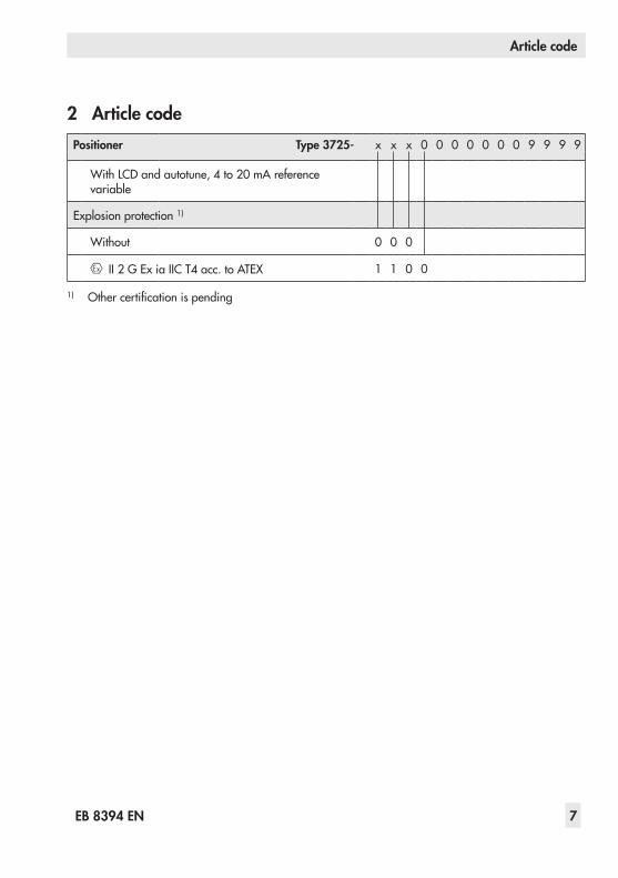
2 Article codePositioner Type 3725- x x x 0 0 0 0 0 0 0 9 9 9 9
WithLCDandautotune,4to20 mAreferencevariable
Explosion protection 1)
Without 0 0 0
II2GExiaIICT4acc.toATEX 1 1 0 0
1) Othercertificationispending

Design and principle of operation
8 EB 8394 EN
3 Design and principle of oper-ation
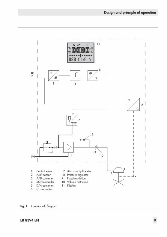
The electropneumatic positioner is mount-edonpneumaticcontrolvalvesandisusedtoassignthevalveposition(controlledvari-able x)tothecontrolsignal(referencevari-able w).Thepositionercomparestheelectriccontrolsignalofacontrolsystemtothetraveloropeningangleofthecontrolvalveandis-suesasignalpressure(outputvariable y)forthepneumaticactuator.Thepositionermainlyconsistsofthefollowingcomponents(seeFig.1): − Anisotropicmagnetoresistive(AMR)sen-sor(2)
− Analogi/pconverter(6)withadown-streamaircapacitybooster(7)
− Electronicsunitwithmicrocontroller(4)Thetraveloropeningangleismeasuredbythepick-upleverconnectedtoamagnetandanon-contactAMRsensor(2)installedinthepositioner and the downstream electronics.Themotionofthepick-uplevercausesthedi-rectionofthemagneticfieldtochange.ThischangeissensedbytheAMRsensor.Theelec-tronicsunitdeterminesthecurrentvalveposi-tionoropeninganglefromthisinformation.Thepositionofthevalveistransmittedtothemicrocontroller(4)overitsA/Dconverter(3).ThePDcontrolalgorithminthemicroproces-sorcomparesthisactualpositiontothe4to20 mAcontrolsignal(referencevariable)afterithasbeenconvertedbytheA/Dconverter(3).Incaseofasystemdeviation,theactiva-tionofthei/pconverter(6)ischangedsothat
theactuatorofthecontrolvalve(1)ispres-surizedorventedaccordinglyoverthedown-streambooster(7).Thesupplyairissuppliedtotheboosterandthepressureregulator(8).The output signal pressure supplied by theboostercanbelimitedto2.4 barbysoftware.ThevolumerestrictionQ(10)isusedtoopti-mizethepositionerbyadaptingittotheac-tuatorsize.
Tight-closing functionThe pneumatic actuator is completely filledwithairorventedassoonas thereferencevariablefallsbelow1 %orexceeds99 %(seeend positions set in P10 and P11 parame-tercodes).Airtoopen(ATO):P10 –>ON;P11 –> OFFAirtoclose(ATC):P10 –>OFF;P11 –>ON
Design and principle of operation
EB 8394 EN 9
%
Smm
%mm
Q
3 4
11
6
7
8
10
1
w
9
xy
2
5
1 Controlvalve2 AMRsensor3 A/Dconverter4 Microcontroller5 D/Aconverter6 i/pconverter
7 Aircapacitybooster 8 Pressureregulator9 Fixed restriction10 Volumerestriction11 Display
Fig. 1: Functional diagram
Design and principle of operation
10 EB 8394 EN
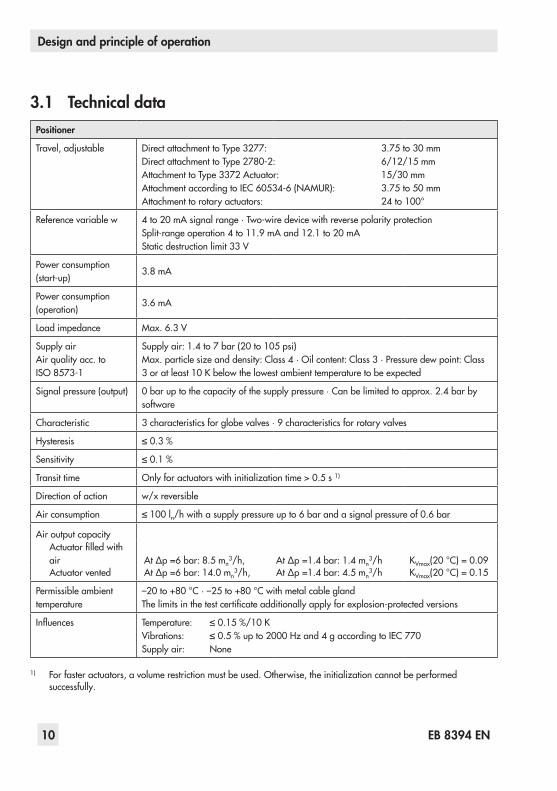
3.1 Technical dataPositioner
Travel,adjustable DirectattachmenttoType3277: 3.75to30 mmDirectattachmenttoType2780-2: 6/12/15mmAttachmenttoType3372Actuator: 15/30mmAttachmentaccordingtoIEC 60534-6(NAMUR): 3.75to50 mmAttachmenttorotaryactuators: 24to100°
Referencevariablew 4to20mAsignalrange·Two-wiredevicewithreversepolarityprotectionSplit-rangeoperation4to11.9mAand12.1to20mAStaticdestructionlimit33 V
Powerconsumption(start-up)
3.8mA
Powerconsumption(operation)
3.6mA
Loadimpedance Max.6.3 V
Supplyair Airqualityacc.toISO 8573-1
Supplyair:1.4to7 bar(20to105 psi) Max.particlesizeanddensity:Class4·Oilcontent:Class3·Pressuredewpoint:Class3oratleast10 Kbelowthelowestambienttemperaturetobeexpected
Signalpressure(output) 0baruptothecapacityofthesupplypressure·Canbelimitedtoapprox.2.4 barbysoftware
Characteristic 3characteristicsforglobevalves·9characteristicsforrotaryvalves
Hysteresis ≤0.3%
Sensitivity ≤0.1%
Transit time Onlyforactuatorswithinitializationtime>0.5s1)
Directionofaction w/xreversible
Airconsumption ≤100ln/hwithasupplypressureupto6 barandasignalpressureof0.6 bar
AiroutputcapacityActuatorfilledwithair AtΔp=6bar:8.5 mn
3/h, AtΔp=1.4bar:1.4 mn3/h KVmax(20°C)=0.09
Actuatorvented AtΔp=6bar:14.0 mn3/h, AtΔp=1.4bar:4.5 mn
3/h KVmax(20°C)=0.15
Permissible ambient temperature
–20to+80°C·–25to+80°Cwithmetalcablegland Thelimitsinthetestcertificateadditionallyapplyforexplosion-protectedversions
Influences Temperature: ≤0.15%/10KVibrations: ≤0.5%upto2000Hzand4gaccordingtoIEC770Supplyair: None
1) Forfasteractuators,avolumerestrictionmustbeused.Otherwise,theinitializationcannotbeperformed successfully.

Design and principle of operation
EB 8394 EN 11
Electromagneticcompatibility
ComplyingwithEN61000-6-2,EN61000-6-3andNAMURRecommendationNE21
Explosion protection II2GExiaIICT4
Degreeofprotection IP66
Materials
Body Polyphthalamide(PPA)
Cover Polycarbonate(transparent)
External parts Stainless steel 1.4571 and 1.4301
Cablegland M20x1.5,blackpolyamide
Venting High-densitypolyethylene(PE-HD)
Weight Approx. 0.5 kg
Attachment to the control valve – Mounting parts and accessories
12 EB 8394 EN
4 Attachment to the control valve – Mounting parts and accessories
NOTICEAttach the positioner, keeping the fol-lowing sequence:
1. Mount the positioner on the control valve2. Connect the supply air3. Connect the electrical power4. Perform the start-up settings
The positioner is suitable for the followingtypesofattachment: − DirectattachmenttoSAMSONType 3277andType 2780-2Actuators
− AttachmentaccordingtoIEC60534-6(NAMUR)
− AttachmenttoType 3372Actuator(Se-riesV2001Valves)
− Attachmenttorotaryactuatorsacc.toVDI/VDE3845
NOTICE − Attach the positioner to the control valve only using the mounting parts and accessories as described in sec-tion 4.5. − Observe the type of attachment! − Observe the assignment between le-ver and pin position!
Lever and pin positionThepositionerisadaptedtotheactuatorandtotheratedtravelbytheleveronthebackofthe positioner and the pin inserted into the le-ver.
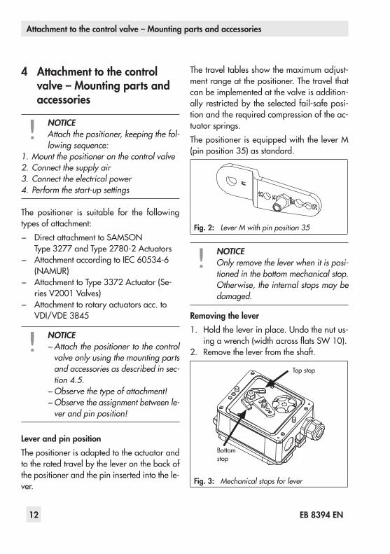
Thetraveltablesshowthemaximumadjust-mentrangeatthepositioner.Thetravelthatcan be implemented at the valve is addition-allyrestrictedbytheselectedfail-safeposi-tionandtherequiredcompressionoftheac-tuatorsprings.ThepositionerisequippedwiththeleverM(pinposition35)asstandard.
Fig. 2: Lever M with pin position 35
NOTICEOnly remove the lever when it is posi-tioned in the bottom mechanical stop. Otherwise, the internal stops may be damaged.
Removing the lever1. Holdtheleverinplace.Undothenutus-
ingawrench(widthacrossflatsSW10).2. Removetheleverfromtheshaft.
Top stop
Bottom stop
Fig. 3: Mechanical stops for lever

Attachment to the control valve – Mounting parts and accessories
EB 8394 EN 13
Travel tables
Note:The lever M is included in the scope of delivery.
Direct attachment to Type 3277-5 and Type 3277 Actuators
Actuator size Rated travel Adjustment range at positioner Required lever
Assigned pin position[cm²] [mm] Min. Travel Max.
120 7.5 5.0 to 16.0 M 25
120/240/350 15 7.0 to 22.0 M 35
355/700 30 10.0 to 32.0 M 50
Direct attachment to Type 2780-2 Actuator
Actuator size Rated travel Adjustment range at positioner Required lever
Assigned pin position[cm²] [mm] Min. Travel Max.
120 6/12 5.0 to 16.0 M 25
120 15 7.0 to 22.0 M 35
Attachment according to IEC 60534-6 (NAMUR)
SAMSON Type 3271 Actuator Travel of other valves [mm] Required lever
Assigned pin position
Size [cm²] Rated travel [mm] Min. Max.
120 7.5 3.5 11.0 S 17
120 7.5 5.0 25.0 M 25
120/240/350 157.0 35.0 M 35
700 7.5
700 15/30 10.0 50.0 M 50
Attachment to rotary actuators acc. to VDI/VDE 3845
Rotary actuators Required lever
Assigned pin positionMin. Openingangle Max.
24° to 100° M 90°

Attachment to the control valve – Mounting parts and accessories
14 EB 8394 EN
4.1 Direct attachment
4.1.1 Type 3277-5 and Type 2780-2 Actuators
Refer to Table 1 on page 27 for the re-quiredmountingpartsandaccessories.Observethetraveltableonpage13.
Actuator with 120 cm²Dependingonthetypeofpositionerattach-ment,thesignalpressureisroutedeitherleftorrightoftheyokethroughaholetotheac-tuatordiaphragm.Dependingonthefail-safeactionoftheac-tuator"Actuatorstemextends"or"Actuatorstemretracts"(valveclosesoropensifthesup-plyairfails),theswitchoverplate(9)mustfirstbeattachedto theactuatoryoke.Aligntheswitchoverplatewiththecorrespondingsym-bolforleftorrightattachmentaccordingtothemarking(viewlookingontotheswitcho-verplate).1. Mount connecting plate (6) or pressure
gaugebracket(7)withpressuregaugesontothepositioner,makingsurebothsealrings(6.1)areseatedproperly.
2. Screwthescrewplug(4)onthebackofthepositionerintotheholebelowit(parkposition)(seeFig.7)andsealthesignalpressureoutputon theconnectingplate(6)oronthepressuregaugebracket(7)with thestopper (5) included in theac-cessories.
3. Place follower clamp (3) on the actua-torstem,alignandscrewtightsothatthe
mountingscrewislocatedinthegrooveoftheactuatorstem.
4. 15mmtravel:Keepthefollowerpin(2)onleverM(1)onthebackoftheposition-erinthepinposition35(deliveredstate).7.5mmtravel:Removethefollowerpin(2)fromthepinposition35,repositionitintheholeforpinposition25andscrewtight.
5. Insertformedseal(15)intothegrooveofthepositionerhousing.
6. Placepositionerontheactuatorinsuchamannerthatthefollowerpin(2)restsontopofthefollowerclamp(3).Whiledo-ingthis,pressontheribbedareashowninFig.4tolockthepick-upleverinthetopposition.Thelever(1)mustrestonthefol-lowerclampwithspringforce.
Fig. 4: Locking the pick-up lever in position
Mountthepositionerontheactuatorusingthetwofixingscrews.

Attachment to the control valve – Mounting parts and accessories
EB 8394 EN 15
9 11Supply 9 Output 38
56
7
3
21
15
6.1
1.11.2
8
4
16
1 Lever1.1Nut1.2Diskspring 2 Follower pin3 Follower clamp4 Screwplug5 Stopper6 Connectingplate6.1 Seal7 Pressuregauge
bracket8 Pressuregauge
mountingkit9 Switchover plate
(actuator)11 Cover15 Formed seal16 Ventplug
Symbols
Actuatorstemextends
Switchoverplate(9)
Marking
Actuatorstemretracts
Signalpressureinputforrightattachment
Signalpressureinputforleftattachment
Note: Always use the connecting plate (6) or pressure gauge bracket (7) in-cluded in the accessories to connect supply and output.Never screw threaded parts directly into the housing. Otherwise, the fi lter will be damaged!
Leftattachment Rightattachment
Fig. 5: Direct attachment – Signal pressure connection for Type 3277-5 Actuator with 120 cm²
Attachment to the control valve – Mounting parts and accessories
16 EB 8394 EN
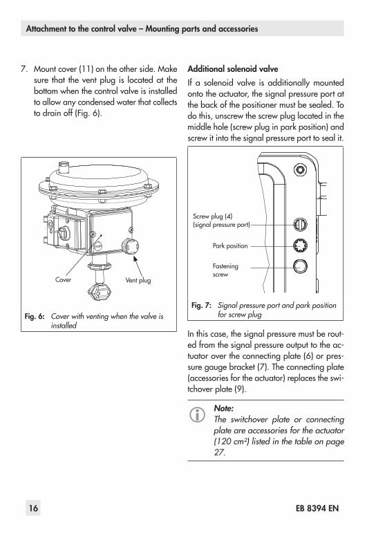
7. Mountcover(11)ontheotherside.Makesure that theventplug is locatedat thebottom when the control valve is installed to allow any condensed water that collects todrainoff(Fig.6).
Cover Ventplug
Fig. 6: Cover with venting when the valve is installed
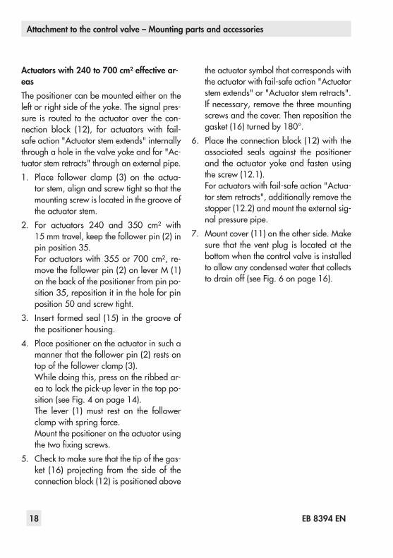
Additional solenoid valveIf a solenoid valve is additionallymountedontotheactuator,thesignalpressureportatthebackofthepositionermustbesealed.Todothis,unscrewthescrewpluglocatedinthemiddlehole(screwpluginparkposition)andscrewitintothesignalpressureporttosealit.
Screwplug(4) (signalpressureport)
Parkposition
Fasteningscrew
Fig. 7: Signal pressure port and park position for screw plug
Inthiscase,thesignalpressuremustberout-edfromthesignalpressureoutputtotheac-tuatorovertheconnectingplate(6)orpres-suregaugebracket(7).Theconnectingplate(accessoriesfortheactuator)replacestheswi-tchoverplate(9).
Note:The switchover plate or connecting plate are accessories for the actuator (120 cm²) listed in the table on page 27.

Attachment to the control valve – Mounting parts and accessories
EB 8394 EN 17
4.1.2 Type 3277 ActuatorRefertosection4.5fortherequiredmountingparts and accessories.Observethetraveltableonpage13.
Note:The actuators with 240 to 700 cm² ef-fective areas are described on the fol-lowing pages.
Fig. 8: Type 3372 Actuator with Type 3725 Positioner (direct attachment)
Attachment to the control valve – Mounting parts and accessories
18 EB 8394 EN
Actuators with 240 to 700 cm² effective ar-easThepositionercanbemountedeitherontheleftorrightsideoftheyoke.Thesignalpres-sure is routed to theactuatorover thecon-nection block (12), for actuators with fail-safeaction"Actuatorstemextends"internallythroughaholeinthevalveyokeandfor"Ac-tuatorstemretracts"throughanexternalpipe.1. Place follower clamp (3) on the actua-
torstem,alignandscrewtightsothatthemountingscrewislocatedinthegrooveoftheactuatorstem.
2. For actuators 240 and 350 cm² with15 mmtravel,keepthefollowerpin(2)inpin position 35.Foractuatorswith355or700 cm², re-movethefollowerpin(2)onleverM(1)onthebackofthepositionerfrompinpo-sition35,repositionitintheholeforpinposition50andscrewtight.
3. Insertformedseal(15)inthegrooveofthepositionerhousing.
4. Placepositionerontheactuatorinsuchamannerthatthefollowerpin(2)restsontopofthefollowerclamp(3).Whiledoingthis,pressontheribbedar-eatolockthepick-upleverinthetoppo-sition(seeFig.4onpage14).The lever (1) must rest on the followerclampwithspringforce.Mountthepositionerontheactuatorusingthetwofixingscrews.
5. Checktomakesurethatthetipofthegas-ket (16)projecting from the sideof theconnectionblock(12)ispositionedabove
theactuatorsymbolthatcorrespondswiththeactuatorwithfail-safeaction"Actuatorstemextends"or"Actuatorstemretracts".Ifnecessary,removethethreemountingscrews and the cover. Then reposition the gasket(16)turnedby180°.
6. Placetheconnectionblock(12)withtheassociated seals against the positionerand theactuatoryokeand fastenusingthescrew(12.1).Foractuatorswithfail-safeaction"Actua-torstemretracts",additionallyremovethestopper(12.2)andmounttheexternalsig-nalpressurepipe.
7. Mountcover(11)ontheotherside.Makesure that theventplug is locatedat thebottom when the control valve is installed to allow any condensed water that collects todrainoff(seeFig.6onpage16).

Attachment to the control valve – Mounting parts and accessories
EB 8394 EN 19
2
10 15 1 2 3 11
1.11.2
12.11216
16
12.2SUPPLY
A
Ansicht A
1
1 LeverM1.2 Nut1.2 Diskspring2 Follower pin3 Follower clamp11 Cover12 Connectionblock12.1 Screw12.2 Stopperorconnectionfor
externalpiping15 Formed seal16 Gasket
Fig. 9: Direct attachment – Signal pressure connection for Type 3277 Actuator with 240 to 700 cm²
ViewA

Attachment to the control valve – Mounting parts and accessories
20 EB 8394 EN
4.2 Attachment according to IEC 60534-6 (NAMUR)
The positioner is attached to the control valve usingaNAMURbracket(10).Refer to Table 3 on page 27 for the re-quiredmountingpartsandaccessories.Observethetraveltableonpage13.1. Screw the two bolts (14) to the brack-
et(9.1)ofthestemconnector(9),placethefollowerplate(3)ontopandusethescrews(14.1)forfastening.
2. MountNAMURbracket(10)usingtheM8screw(11)andtoothedlockwasherdi-rectlytotheyokehole.AligntheNAMURbracket (10) so that its mounting holesare approximately in line with the mid-dleofthetravelscaleindicator(15)(theslotofthefollowerplatemustbecentrallyalignedwiththeNAMURbracketatmidvalvetravel).
3. Mount connecting plate (6) or pressuregaugebracket(7)withpressuregauges(8)onthepositioner,makingsurethetwoseals(6.1)areseatedproperly.
4. PlacepositionerontheNAMURbracketinsuchamannerthatthefollowerpin(2)restsintheslotofthefollowerplate(3).Adjustthelever(1)correspondingly.ScrewthepositionertotheNAMURbrack-etusingbothitsmountingscrews.

Attachment to the control valve – Mounting parts and accessories
EB 8394 EN 21
10
11
14.1
3
14
11.21.12
9.1
9
6.1 6 7 81 Lever1.1 Nut1.2 Diskspring 2 Follower pin 3 Follower plate6 Connectingplate6.1 Seal7 Pressuregauge
bracket8 Pressuregauge 9 Stem connector9.1 Bracket10 NAMURbracket11 Screw14 Bolt14.1 Screws15 Travel indicator scale
15
Fig. 10: Attachment according to IEC 60534-6 (NAMUR)
Attachment to the control valve – Mounting parts and accessories
22 EB 8394 EN

Attachment to the control valve – Mounting parts and accessories
EB 8394 EN 23
4.3 Attachment to Type 3372 Actuator (V2001)
TheType3725Positionerisalreadyinclud-edinthescopeofdeliveryforSeriesV2001Valves(Type 3372Actuator).Theattachmentisbrieflydescribedbelowtoallowconversionworktobeperformed.
Actuator with 120/350 cm², stem extendsThesignalpressureisroutedthroughthecor-respondingportinthesupportelementtotheactuatordiaphragm.Threadthescrewplugonthepositionerintotheholebelow(parkposition)(seeFig.7onpage16).
Actuator with 120/350 cm², stem retractsThesignalpressureisroutedthroughpipingatthesideofthesupportelementtotheactu-atordiaphragm.
Attachment including solenoid valveThesignalpressureisroutedfromtheoutputport of thepositioner to the solenoid valveandthroughacorrespondingholeinthesup-portelementtotheactuatordiaphragm.
Type3372Actuator,version120cm²effectivearea
Type3372Actuator,version350cm²effectivearea
Fig. 11: Mounting on Type 3372 Actuator

Attachment to the control valve – Mounting parts and accessories
24 EB 8394 EN
4.4 Attachment to rotary actu-ators
Thepositionerismountedtotherotaryactua-torusingamountingbracket.Refer to Table 4 on page 28 for the re-quiredmountingpartsandaccessories.Before attaching the positioner onto theSAMSON Type 3278 Rotary Actuator(160 cm²)orVETECType S160Actuator,firstmounttheadapter(13)tothefreeendoftheshaftendusingfourscrews(11,12).
NOTICEOn attaching the positioner as de-scribed below, it is imperative that the actuator's direction of rotation is ob-served.
1. Placefollowerclamp(3)ontheslottedac-tuatorshaftoradapter(13).
2. Place coupling wheel (4) with flat sidefacingtheactuatoronthefollowerclamp(3).RefertoFig.12toalignslotsothatitmatchesthedirectionofrotationwhenthevalve is in its closed position.
3. Fastenthecouplingwheel(4)andfollow-erclamp(3)tightlyontotheactuatorshaftusingscrew(4.1)anddiskspring(4.2).
4. Mount connecting plate (6) or pressuregaugebracket(7)withpressuregauges(8)onthepositioner,makingsurethetwoseals are seated properly.
5. Fasten themountingbracket (10) to theactuatorusingfourscrews(10.1).
6. Unscrew the standard follower pin (2)fromthepositioner'sleverM(1).Usethemetalfollowerpin(Ø5 mm)includedinthemountingkitandscrewtightintotheholeforpinposition90°.
7. Placepositioneronthemountingbrack-et(10)andscrewtight.Takingtheactua-tor'sdirectionofrotationintoaccount,ad-justlever(1)sothatitengagesintheslotofthecouplingwheel(4)withitsfollowerpin(Fig.13).Itmustbeguaranteedthatthelever(1)isparalleltothelongsideofthepositionerwhentheactuatorisathalfitsangleofrotation.
8. Stickthescalelabelonthecouplingwheel(4) so that the arrow tip indicates theclosed position and it can be easily read when the valve is installed.
Fig. 12: Direction of rotation

Attachment to the control valve – Mounting parts and accessories
EB 8394 EN 25
8050
60
30
66.178
11.11.2
2
4.1
3
10.1
10
5
4
4.2
30
5080
66.178
11.11.2
2
4.1
3
10.1
10
5
13
10.1
4
4.2
1 Lever1.2 Nut1.2 Diskspring2 Follower pin3 Follower clamp4 Couplingwheel4.1 Screw4.2 Diskspring5 Actuatorshaft
6 Connectingplate6.1 Seal7 Pressuregauge
bracket8 Pressuregauge
mountingkit10 Mountingbracket10.1 Screws13 Adapter
AttachmenttoVETECType S160Actuatoror SAMSONType3278RotaryActuator,
160cm²
AttachmentaccordingtoVDI/VDE 3845, level 1
Fig. 13: Attachment to rotary actuators
Attachment to the control valve – Mounting parts and accessories
26 EB 8394 EN
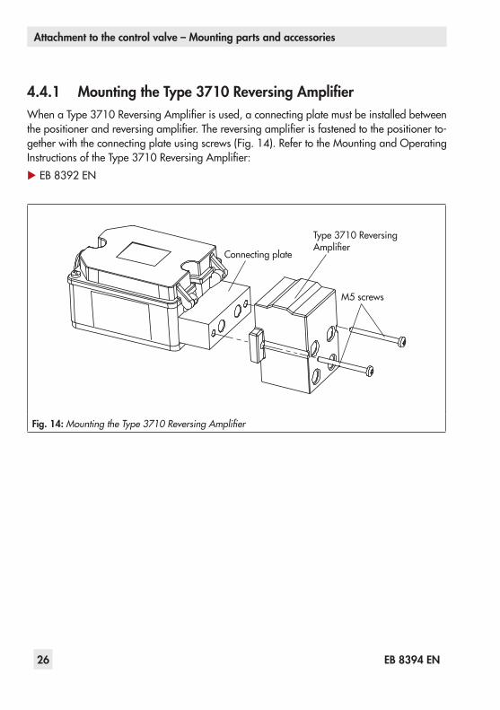
4.4.1 Mounting the Type 3710 Reversing AmplifierWhenaType 3710ReversingAmplifierisused,aconnectingplatemustbeinstalledbetweenthepositionerandreversingamplifier.Thereversingamplifierisfastenedtothepositionerto-getherwiththeconnectingplateusingscrews(Fig.14).RefertotheMountingandOperatingInstructionsoftheType 3710ReversingAmplifier:uEB8392EN
Connectingplate
Type3710ReversingAmplifier
M5screws
Fig. 14: Mounting the Type 3710 Reversing Amplifier

Attachment to the control valve – Mounting parts and accessories
EB 8394 EN 27
4.5 Required mounting parts and accessories
Table 1: Direct attachment to Types 3277-5 and 3277 Actuators (section 4.1) Order no.
Mountingparts Mountingpartsforactuatorswith120cm²effectiveareaorsmaller 1402-0239
Accessoriesforactuator
SwitchoverplateforType3277-5xxxxxx.01Actuator 1400-6822Connectingplateforadditionalattachment,e.g.solenoidvalve:G1/8 1400-6820
Accessoriesforpositioner
Connectingplate(6)G¼ 1402-0235¼NPT 1402-0236
Pressuregaugebracket(7)G¼ 1402-0237¼NPT 1402-0238
Pressuregaugemountingkit(8),uptomax.6bar(output/supply)
St.steel/brass 1400-6950St.steel/st.steel 1400-6951
Table 2: Direct attachment to Type 3277 Actuator (section 4.1.2) Order no.
Mountingparts Attachmenttoactuatorswith240,350,355and700cm² 1402-0240
AccessoriesConnectionblockwithsealsandscrew
G¼ 1402-0241¼NPT 1402-0242
Pressuregaugemountingkituptomax.6bar(output/supply)
St.steel/brass 1400-6950St.steel/st.steel 1400-6951
Table 3: Attachment to NAMUR ribs according to IEC 60534-6 (section 4.2)Travel [mm] Lever Foractuators Order no.3.75 to 50 Without,already
on positionerActuatorsfromothermanufacturersandType 3271with120to700cm²effectiveareas 1402-0330
Accessories
ConnectingplateG¼ 1402-0235¼NPT 1402-0236
PressuregaugebracketG¼ 1402-0237¼NPT 1402-0238
Pressuregaugemountingkituptomax.6bar(output/supply)
St.steel/brass 1400-6950St.steel/st.steel 1400-6951
Attachment to the control valve – Mounting parts and accessories
28 EB 8394 EN
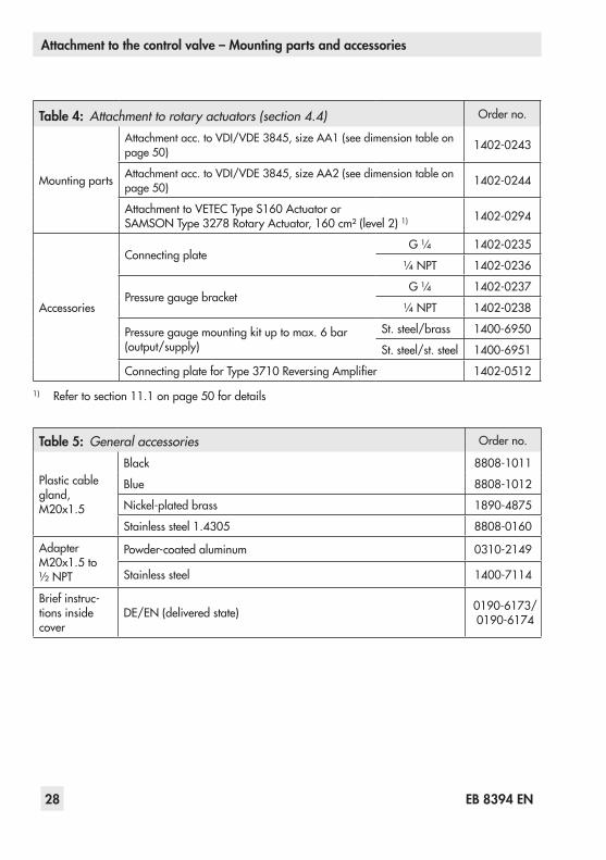
Table 4: Attachment to rotary actuators (section 4.4) Order no.
Mountingparts
Attachmentacc.toVDI/VDE3845,sizeAA1(seedimensiontableonpage50) 1402-0243
Attachmentacc.toVDI/VDE3845,sizeAA2(seedimensiontableonpage50) 1402-0244
AttachmenttoVETECType S160Actuatoror SAMSONType3278RotaryActuator,160cm²(level2)1) 1402-0294
Accessories
ConnectingplateG¼ 1402-0235
¼NPT 1402-0236
PressuregaugebracketG¼ 1402-0237
¼NPT 1402-0238
Pressuregaugemountingkituptomax.6bar(output/supply)
St.steel/brass 1400-6950
St.steel/st.steel 1400-6951
ConnectingplateforType 3710ReversingAmplifier 1402-0512
1) Refertosection11.1onpage50fordetails
Table 5: General accessories Order no.
Plastic cable gland,M20x1.5
Black 8808-1011
Blue 8808-1012
Nickel-platedbrass 1890-4875
Stainless steel 1.4305 8808-0160
AdapterM20x1.5to½ NPT
Powder-coatedaluminum 0310-2149
Stainless steel 1400-7114
Briefinstruc-tions inside cover
DE/EN(deliveredstate) 0190-6173/ 0190-6174

Connections
EB 8394 EN 29
5 Connections
5.1 Pneumatic connections
NOTICEThe threaded connections in the po-sitioner housing are not designed for the direct connection of pneumatic fit-tings!
The screwfittingsmustbe screwed into theconnectingplate,thepressuregaugemount-ingblockortheconnectionblockfromtheac-cessories. Their pneumatic connections areoptionallydesignedasaborewith¼NPTorG¼thread.Thecustomaryfittingsformet-al and copper pipes or plastic hoses can be used.Keepthelengthofthelineasshortaspossibletoavoiddelaysincontrolsignaltransmission.
NOTICEThe supply air must be dry and free from oil and dust. The maintenance in-structions for upstream pressure reduc-ing stations must be observed.Blow through all air pipes and hoses thoroughly prior to connecting them.
Thesignalpressureconnectionisfixedwhenthe positioner is directly attached to the Type 3277Actuator.For attachment according to IEC 60534-6(NAMUR),thesignalpressurecanberoutedtoeitherthetoporbottomdiaphragmcham-beroftheactuator,dependingontheactua-
tor'sfail-safeaction"Actuatorstemextends"or"Actuatorstemretracts".Forrotaryactuators,themanufacturer'sspec-ificationsforconnectionapply.
5.1.1 Signal pressure gaugesTomonitor the supplyair (supply)andsig-nalpressure(output),werecommendmount-ingpressuregauges(seeaccessoriesinsec-tion 4.5).
5.1.2 Supply pressureTherequiredsupplyairpressuredependsonthebenchrangeandtheactuator'soperatingdirection(fail-safeaction).Thebenchrangeisregisteredonthenameplateeitherasspringrangeorsignalpressurerangedependingontheactuator.ThedirectionofactionismarkedFAorFE,orbyasymbol.
Actuator stem extends FA (air to open)Fail-safeposition"ValveClosed"(forglobeandanglevalves): Requiredsupplypressure=Upperbenchrangevalue+0.2 bar,minimum1.4bar.

Connections
30 EB 8394 EN
Actuator stem retracts FE (air to close)Fail-safe position "Valve Open" (for globeandanglevalves):Fortight-closingvalves,themaximumsignalpressurepstmaxisroughlyestimatedasfollows:
pstmax ==F + d²·π·∆p [bar]4·A
d =Seatdiameter[cm]∆p =Differentialpressureacrossthevalve[bar]A =Actuatordiaphragmarea[cm²]F =Upperbenchrangevalue[bar]
If there are no specifications, calculate as follows:Required supply pressure = Upper benchrangevalue+1bar
Note:The signal pressure at the output (38) of the positioner can be restricted to approx. 2.4 bar by setting P9 param-eter code to ON.
5.2 Electrical connections
DANGER!Risk of electric shock and/or the for-mation of an explosive atmosphere!
− For electrical installation, observe the relevant electrotechnical regu-lations and the accident prevention regulations that apply in the coun-try of use. The following regulation applies to mounting and installation in hazardous areas: EN 60079-14: Explosive atmospheres – Part 14: Electrical installations design, selec-tion and erection. − Avoid electrostatic charging of the plastic housing when mounting and servicing the positioner in hazard-ous areas.
NOTICE − Do not loosen enameled screws in or on the housing. − The maximum permissible values (Ui, Ii, Pi, Li and Ci) specified in the EC-type examination certificate ap-ply when interconnecting intrinsical-ly safe electrical equipment).
NOTICEOnly a current source must be used for the electrical supply. Do not use a volt-age source!

Connections
EB 8394 EN 31
Selecting cables and wiresObserve EN 60079-14 and particularlyClause12 in itwhen installing intrinsicallysafecircuits.TheSubclause12.2.2.7applieswhenrunningmulti-corecablescontainingmorethanoneintrinsicallysafecircuit.Theminimumradialthicknessoftheconduc-torinsulationmustbesuitablefortheconduc-tordiameterandtypeofinsulation.Itmustbeatleast0.2 mm.Thediameterofanindividualwireinafine-strandedconductormustnotbesmallerthan0.1 mm.Protect theconductorendsagainstsplicing,e.g.byusingwire-endferrules.
Equipment for use in zone 2InequipmentoperatedwithtypeofprotectionEx nA(non-sparkingequipment)accordingtoEN60097-15,circuitsmaybeconnected,interruptedorswitchedwhileenergizedon-lyduringinstallation,maintenanceorrepair.
Cable entryTheM20x1.5cableglandisdesignedforaclampingrangeof6to12 mm.Thecageclampterminalsholdwirecross-sec-tionsof0.2to1.5 mm²andadditionallyhavetestconnectionsfor1 mmprobetips.
Notchonplasticpart
Fig. 15: Cage clamp terminal
NOTICEApplying excessive force to the cage clamp terminals may damage them.
Thetestconnectionsarealsousedtounlockthe cage clamp terminals: place a slottedscrewdriveronthenotchoftheplasticpartofthetestconnection(Fig.15)andpressdown,whileinsertingorremovingthewire.Thewiresforthereferencevariablemustbeconnected to the terminals 11 and 12 locat-edinthehousing.
NOTICEThe static destruction limit of the posi-tioner is at ± 33 V. Do not allow the input signal to fall below the lowest permissible value of 3.8 mA for posi-tioner operation.

Connections
32 EB 8394 EN
Accessories:Plasticcablegland,M20x1.5 − Black Orderno.8808-1011 − Blue Orderno.8808-1012 − Nickel-platedbrass Orderno.1890-4875
− Stainless steel 1.4305 Orderno.8808-0160
AdapterM20x1.5to½NPT − Powder-coatedaluminum
Order no. 0310-2149 − Stainless steel Order no. 1400-7114
mAcontrolsignal
+11 -12
Fig. 16: Electrical connections

Operation
EB 8394 EN 33
6 OperationThreecapacitivekeysandaLCDareusedtooperatethepositioner(seebelow).Toadapttheaircapacity,thevolumerestric-tionmustbeadjusted(section7.3).
6.1 Operating controlsTouch or to select a parameter code (P0 to P20).Thentouch toconfirmthese-lected code.
NOTICEAny parameter code settings that have been changed are first saved in a non-volatile memory after the display has returned to the display with status in-dication. Go to Code P0 by touching
or or wait three minutes until the display returns automatically.The icon on the display indicates that the changed parameter settings have not yet been saved in the non-volatile memory.
Note:After changing settings in P2, P3, P4, P8 and P9 parameter codes, the posi-tioner must be re-initialized.
%
Smm
%mm
Confirm
Up
Settingsnotyetsavedinanon-volatile memory
Unit
Bargraphforsystemdeviation
Fault
Manualmode
Closed-loopoperation
Parameter/errorcode
Fail-safepositionactive
Operationlocked
Down
Fig. 17: Capacitive keys and display
Start-up and settings
34 EB 8394 EN
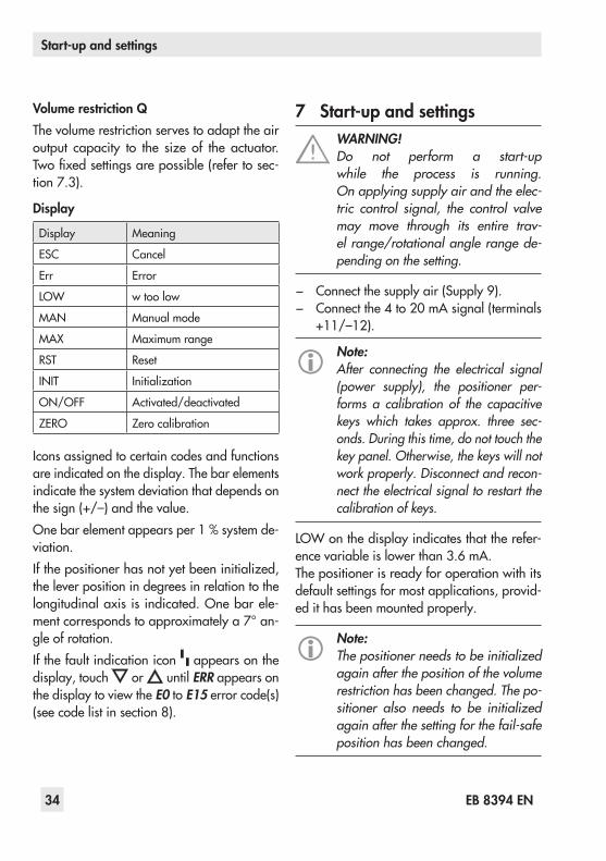
Volume restriction QThevolumerestrictionservestoadapttheairoutput capacity to the size of the actuator.Twofixedsettingsarepossible(refertosec-tion7.3).
Display
Display Meaning
ESC Cancel
Err Error
LOW w too low
MAN Manualmode
MAX Maximumrange
RST Reset
INIT Initialization
ON/OFF Activated/deactivated
ZERO Zero calibration
Iconsassignedtocertaincodesandfunctionsare indicated on the display. The bar elements indicate the system deviation that depends on thesign(+/–)andthevalue.Onebarelementappearsper1 %systemde-viation.Ifthepositionerhasnotyetbeeninitialized,theleverpositionindegreesinrelationtothelongitudinalaxisis indicated.Onebarele-mentcorrespondstoapproximatelya7°an-gleofrotation.Ifthefaultindicationicon appears on the display,touch or untilERR appears on the display to view the E0 to E15errorcode(s)(seecodelistinsection8).
7 Start-up and settingsWARNING!Do not perform a start-up while the process is running. On applying supply air and the elec-tric control signal, the control valve may move through its entire trav-el range/rotational angle range de-pending on the setting.
− Connectthesupplyair(Supply9). − Connectthe4to20mAsignal(terminals+11/–12).
Note:After connecting the electrical signal (power supply), the positioner per-forms a calibration of the capacitive keys which takes approx. three sec-onds. During this time, do not touch the key panel. Otherwise, the keys will not work properly. Disconnect and recon-nect the electrical signal to restart the calibration of keys.
LOWonthedisplayindicatesthattherefer-encevariableislowerthan3.6 mA.Thepositionerisreadyforoperationwithitsdefaultsettingsformostapplications,provid-edithasbeenmountedproperly.
Note:The positioner needs to be initialized again after the position of the volume restriction has been changed. The po-sitioner also needs to be initialized again after the setting for the fail-safe position has been changed.

Start-up and settings
EB 8394 EN 35
Reading after connecting the electrical sig-nalThe faultindicationiconandundS(fail-safeposition)appearonthedisplaywhenthepo-sitionerhasnotyetbeeninitialized.Theread-ingindicatestheleverpositionerindegreesrelativetothelongitudinalaxis.
S
Reading when the posi-tioner has not yet been initialized
− CodeP0appearsonthedisplayaftercon-nectingtheelectricalsignaltoaninitial-izedpositioner.
7.1 Adapting the display direc-tion
The data representation on the positioner dis-playcanbeturnedby180°.If thedisplayeddataappearupsidedown,proceedasfollows:Touch or untilCodeP1 appears.Touch to confirm the selected code.P1blinks.
Reading direction for right attachment of pneumatic connections
Touch or untiluntilthedisplayissetinthe desired direction.Touch toconfirmdisplaydirection.
7.2 Enabling configuration
Note:Before changing parameter settings, configuration must be enabled first by selecting Code P19.
Enabling configuration with Code 19
If no settings are entered within three minutes, the enabled configuration function becomes invalid. Touch or untilCodeP19 appears.
Touch toconfirmtheselectedcode.P19blinks.Touch untilOPENappearsonthedisplay.Touch tounlockoperation.
NOTICEDuring start-up, the actuator stem moves.Do not touch the actuator stem or ob-struct it to avoid risk of injury to hands or fingers.
The permissible range has been exceededwhenthedisplayedangleismorethan30°.Thepositionergoes to the fail-safeposition(SAFE).Make sure that the lever and pin positionmatch the details as described in section 4.

Start-up and settings
36 EB 8394 EN
Note:The positioner has a function to moni-tor the working range.If the lever moves too close to the me-chanical stops (risk of mechanical damage), the positioner vents the ac-tuator and the valve moves to its fail-safe position (S displayed together with E8 error code).In this case, check the positioner at-tachment. Reset the displayed error code by selecting RST (see section 7.11).
7.3 Adjusting the volume re-striction Q
Fig. 18: Volume restriction QMAX/MIN setting
ThevolumerestrictionQservestoadapttheairoutputcapacitytothesizeoftheactuator: − Actuatorswithatransit time < 1 s,e.g.linear actuators with an effective areasmallerthan240 cm²,requirearestrict-edairflowrate.SettingtoMIN
− Actuatorswithatransit time ≥ 1 s do not requiretheairflowratetoberestricted.SettingtoMAX
Intermediatesettingsarenotpermitted.
NOTICEThe positioner needs to be initialized again after the position of the restric-tion has been changed.
Start-up and settings
EB 8394 EN 37
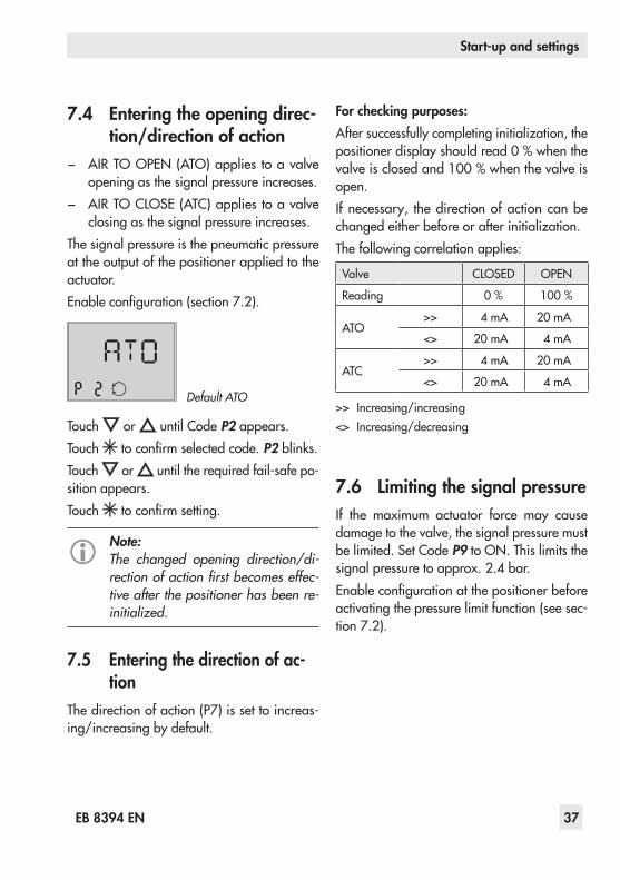
7.4 Entering the opening direc-tion/direction of action
− AIRTOOPEN(ATO)applies toavalveopeningasthesignalpressureincreases.
− AIRTOCLOSE(ATC)appliestoavalveclosingasthesignalpressureincreases.
Thesignalpressureisthepneumaticpressureattheoutputofthepositionerappliedtotheactuator.Enableconfiguration(section7.2).
Default ATO
Touch or untilCodeP2 appears.Touch toconfirmselectedcode.P2blinks.Touch or untiltherequiredfail-safepo-sition appears.Touch toconfirmsetting.
Note:The changed opening direction/di-rection of action fi rst becomes effec-tive after the positioner has been re-initialized.
7.5 Entering the direction of ac-tion
Thedirectionofaction(P7)issettoincreas-ing/increasingbydefault.
For checking purposes:Aftersuccessfullycompletinginitialization,thepositionerdisplayshouldread0 %whenthevalveisclosedand100 %whenthevalveisopen.Ifnecessary, thedirectionofactioncanbechangedeitherbeforeorafterinitialization.Thefollowingcorrelationapplies:
Valve CLOSED OPEN
Reading 0% 100%
ATO>> 4mA 20mA
<> 20mA 4mA
ATC>> 4mA 20mA
<> 20mA 4mA
>> Increasing/increasing<> Increasing/decreasing
7.6 Limiting the signal pressureIf the maximum actuator force may causedamagetothevalve,thesignalpressuremustbelimited.SetCodeP9toON.Thislimitsthesignalpressuretoapprox.2.4 bar.Enableconfigurationatthepositionerbeforeactivatingthepressurelimitfunction(seesec-tion7.2).

Start-up and settings
38 EB 8394 EN
7.7 Setting other parametersThe following table lists all the parametercodesandtheirdefaultsettings.Ifyouwanttochangethedefaultsettingofaparameter,proceedinthesamemanneraspreviouslyde-scribed.
Note:The selected parameter code remains active until you change the setting or exit the parameter code.
Moredetailsconcerningtheparametercodescanbefoundinsection8.
Parametercodes[Defaultsetting] Codesmarkedwith*indicatethattheposition-erneedstobere-initializedafterwards
P0 Operation
P1 Readingdirection
P2* Fail-safeposition[ATO]
P3* Pin position [35]
P4* Nominalrange[MAX]
P5 Characteristic[1]
P6 Referencevariable[4to20mA]
P7 w/xdirectionofaction[>>]
P8* GainKp[50]
P9 Pressurelimit2.4bar[OFF]
P10 Endpositionw<[ON]
P11 End position w > [OFF]
P14 Displayofreferencevariablew
P15 INITStartinitialization
P16 ZEROStartzerocalibration
Parametercodes[Defaultsetting] Codesmarkedwith*indicatethattheposition-erneedstobere-initializedafterwards
P17 Manualmode
P18 Reset
P19 Enableconfiguration
P20 Readfirmware

Start-up and settings
EB 8394 EN 39
7.8 InitializationDuringinitializationthepositioneradaptsit-selfoptimallytothefrictionconditionsandthesignalpressurerequiredbythecontrolvalve.
WARNING!During the initialization, the control valve moves through its entire travel range/angle of rotation.Therefore, do not start initialization while a process is running, but on-ly during start-up, when all shut-off valves are closed.
The type and extent of self-adaptation de-pends on the preset parameters.MAX is the default setting for the nominalrange(CodeP4).Duringtheinitializationprocess,theposition-erdeterminesthetravelrange/angleofrota-tionofthevalve(fromtheCLOSEDpositiontotheotherendposition).Alternatively,adifferenttravelcanbeselectedinCodeP4(seecodelistinsection8).
Note:The travel set in Code P4 is only lim-ited during initialization. However, it might be exceeded in closed-loop con-trol when the control signal is higher than 20 mA.
StartinitializationbyactivatingCodeP15 as follows:
Touch or toselectCodeP15.Touch six seconds long.6-5-4-3-2-1- is counted down on the display.Initialization starts. INIT blinks on the display!
Note:The time required for the initialization procedure depends on the actuator transit time and can take a few minutes.
%Initialization successfully completed, positioner runs in closed-loop operation
Afterasuccessfulinitialization,theposition-errunsinclosed-loopoperationindicatedbythe
%
closed-loop operation icon and con-trolpositionin%predeterminedbytherefer-encevariableonthedisplay.Configurationislocked.Amalfunctionleadstotheprocessbeingin-terrupted and the positionermoving to thefail-safeposition.Thefaultindicationiconap-pearsonthedisplay.Refertosection7.12.
S
Initialization canceled

Start-up and settings
40 EB 8394 EN
Canceling initializationTheinitializationcanbecanceledbytouch-ing .
− ESCblinksonthedisplay. − Touch toconfirm.
Note:This code must be confirmed by touch-ing . Otherwise, the code remains active.
Case 1:Apositionerthathasnotyetbeenini-tializedgoestothefail-safepositionaftertheinitializationprocesshasbeencanceled.Case 2:TheinitializedpositionergoestoAU-TOmodeafterthere-initializationprocesshasbeencanceled.Thesettingsof thepreviousinitializationareused.Anewinitializationcanbestarteddirectlyaf-terwards.
7.9 Zero calibrationIncaseofinconsistenciesintheclosingposi-tionofthevalve,e.g.withsoft-seatedplugs,itmightbenecessarytorecalibratezero.En-ableconfigurationasdescribedinsection7.2.StartthezerocalibrationbyactivatingCodeP16asfollows:
Touch or untilCodeP16 appears.Touch six seconds long.6-5-4-3-2-1- is counteddownonthedisplay.Zero calibration starts, the display blinks!The positioner moves the control valve to the CLOSEDpositionandrecalibratestheinternalelectriczeropoint.When the zero calibration has been suc-cessfullycompleted,thepositionerreturnstoclosed-loopoperation(displaywithstatusin-dication).

Start-up and settings
EB 8394 EN 41
Canceling zero calibrationThe zero calibration can be canceled bytouching .
− ESCblinksonthedisplay. − Touch toconfirm.
Note:This code must be confirmed by touch-ing . Otherwise, the code remains active.
Thepositionerreturnstoclosed-loopopera-tionwithoutperformingazerocalibration.Anewzerocalibrationcanbestarteddirect-lyafterwards.
7.10 Manual modeThevalvepositioncanbemovedasfollowsusingtheManual modefunction:Enableconfiguration(section7.2).Touch or untilCodeP17 appears.Touch six seconds long.6-5-4-3-2-1- is counteddownonthedisplay.P17blinks.Themanualsetpoint(wman)isindicatedonthedisplayofaninitializedpositioner.
%
Theleverpositionindegreesinrelationtothelongitudinalaxisisindicatedonthedisplayofapositionerthathasnotbeeninitialized.
Touch or to change themanual setpoint.
Initialized positionerThemanualmodestartsusingthelastsetpointoftheautomaticmode,ensuringabumplesschangeover.The bar elements on the display indicate the systemdeviationbetweenthemanualandau-tomaticsetpointwhilemanuallymovingthevalveinCodeP17.

Start-up and settings
42 EB 8394 EN
Themanualsetpoint isadjustedinstepsof0.1%.Youcanmovethevalvecontrolledwith-initsrange.Positioner that has not yet been initializedTouch or longer tomove the valvemanually.Thevalveisonlymovedinonedirectionun-controlled. The bar elements on the display in-dicatethechangeindirection.Touch to deactivate the Manual modefunc-tion.
Note:The Manualmode function can only be exited as described or by interrupting the electrical supply (cold start). The positioner does not automatically exit this function and return to the display with status indication.
7.11 ResetThe positioner is in closed-loop operation after the initialization has been successful-ly completed.Aresetcausesaninitializationtobeundoneandallparameterssettingsareresettothede-faultsettings(seecodelistinsection 8).Enableconfiguration(section7.2).Touch or untilCodeP18 appears.Touch six seconds long.6-5-4-3-2-1- is counteddownonthedisplay.RSTblinks.
Afterthepositionerhasbeenreset,thedisplayautomaticallyreturnstostatusindication(P0).Inthisdisplay,theangleisindicatedinde-greesrelativetothelongitudinalaxis.
S

Start-up and settings
EB 8394 EN 43
7.12 FaultsOntheoccurrenceofafault,thefaultindica-tion icon appearsatthebottomofthedis-play.Ifthefaultindicationiconappearsafterapa-rametercodesettinghasbeenchanged,thisindicatesthatthissettingdoesnotmatchthevaluesdeterminedduringinitialization.SeeCodeE1(seecodelistinsection8).Touch or pastCodeP0 or P20,there-spective error code E0 to E15togetherwithERR appear on the display.Refertothecodelistforthecauseoftheerrorsand the recommended action.Example:If,forinstance,atravelhasbeenenteredinCodeP4(nominalrange)whichislargerthanthemaximumvalvetravelpossible,theinitial-izationprocesswouldbeinterrupted(E2 er-rorcode)becausetheratedtravelwouldnothavebeenreached(E6errorcode).Thevalvemovestothefail-safeposition(S indicated on thedisplay).
S
Display of the fault indication
S S
The nominal range (Code P4) must bechangedandthepositionerre-initializedtoremedy this problem.Reset error codesThe E0 and E8 error codes can be reset as follows:
Touch or untiltheerrorcodeappears.Touch toconfirmtheerrorcode.ESC ap-pears on the display.Touch or untilRSTappears.Touch six seconds long.6-5-4-3-2-1- is counteddownonthedisplay.Touch to reset the error.The reset procedure can be canceled bytouching whenESCappears.

Code list
44 EB 8394 EN
8 Code listCode Display, values
[default setting]Description
Parametercodes·Codesmarkedwith*indicatethepositionerneedstobere-initializedafterwards
P0 Statusindicationmodeofthedisplayshowingbasicinformation Thereadingindicatesthevalvepositionortheangleofrotationin%whenthepositionerisinitialized. Thepositionoftheleverinrelationtothemid-axisisindicatedindegreeswhen istouchedandthepositionerhasnotyetbeeninitialized.
P1 Reading direction Thereadingdirectionofthedisplayisturnedby180°.
P2* ATO / ATC [ATO]
Parametertoadaptthepositionertohowthecontrolvalvefunc-tions: ATO–Airtoopen(valveCLOSEDinfail-safeposition) ATC–Airtoclose(valveOPENinfail-safeposition)
P3* Pin position 17/25/[35]/50/90°
Thefollowerpinmustbemountedintheproperpositiondepend-ingonthevalvetravel/openingangle. (selectaccordingtothetraveltablesonpage13).
P4* Nominal range [MAX]Valueswith defaultsetting[35]: e.g. 7.5/8.92/10.6/12.6/ 15.0/17.8/21.2mm
Firmware 1.03 and lower:Thepossibleadjustmentrangecanbeselectedinstagesdependingontheselectedpinposition:
17 3.75 to 10.6mm25 5.3 to 15.0 mm35 7.5 to 21.2 mm50 10.6 to 30.0 mm
For 90° Maximumrangeonly,ifP3=90° MAX Maximumpossibletravel
Nominal range [MAX]
Firmware 1.10 and higher:Thepossibleadjustmentrangecanbeselectedinstepsof0.5 mmdependingontheselectedpinposition:
17 3.5 to 11.0 mm,alternativelyMAX25 5.0 to 16.0mm,alternativelyMAX35 7.0 to 22.0 mm,alternativelyMAX50 10.0 to 32.0 mm,alternativelyMAX
For 90° Maximumrangeonly,ifP3=90° MAX Maximumpossibletravel
Code list
EB 8394 EN 45
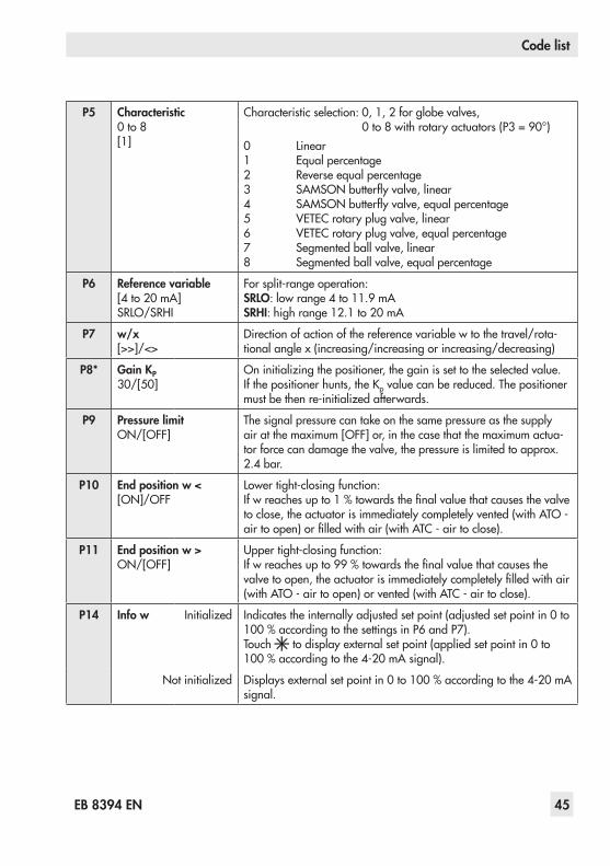
P5 Characteristic 0to8 [1]
Characteristicselection:0,1,2forglobevalves, 0to8withrotaryactuators(P3=90°)0 Linear 1 Equalpercentage 2 Reverseequalpercentage 3 SAMSONbutterflyvalve,linear 4 SAMSONbutterflyvalve,equalpercentage 5 VETECrotaryplugvalve,linear 6 VETECrotaryplugvalve,equalpercentage 7 Segmentedballvalve,linear 8 Segmentedballvalve,equalpercentage
P6 Reference variable [4to20mA] SRLO/SRHI
Forsplit-rangeoperation: SRLO:lowrange4to11.9mA SRHI:highrange12.1to20mA
P7 w/x [>>]/<>
Directionofactionofthereferencevariablewtothetravel/rota-tionalanglex(increasing/increasingorincreasing/decreasing)
P8* Gain KP 30/[50]
Oninitializingthepositioner,thegainissettotheselectedvalue. Ifthepositionerhunts,theKpvaluecanbereduced.Thepositionermustbethenre-initializedafterwards.
P9 Pressure limit ON/[OFF]
Thesignalpressurecantakeonthesamepressureasthesupplyairatthemaximum[OFF]or,inthecasethatthemaximumactua-torforcecandamagethevalve,thepressureislimitedtoapprox.2.4 bar.
P10 End position w < [ON]/OFF
Lowertight-closingfunction: Ifwreachesupto1%towardsthefinalvaluethatcausesthevalvetoclose,theactuatorisimmediatelycompletelyvented(withATO-airtoopen)orfilledwithair(withATC-airtoclose).
P11 End position w > ON/[OFF]
Uppertight-closingfunction: Ifwreachesupto99%towardsthefinalvaluethatcausesthevalvetoopen,theactuatorisimmediatelycompletelyfilledwithair(withATO-airtoopen)orvented(withATC-airtoclose).
P14 Info w Initialized Indicatestheinternallyadjustedsetpoint(adjustedsetpointin0to100%accordingtothesettingsinP6andP7). Touch todisplayexternalsetpoint(appliedsetpointin0to100%accordingtothe4-20mAsignal).
Notinitialized Displaysexternalsetpointin0to100%accordingtothe4-20mAsignal.

Code list
46 EB 8394 EN
P15 Start initialization Theinitializationprocesscanbeinterruptedbytouching . The controlvalvemovestoitsfail-safeposition. Afterapowersupplyfailureduringinitialization,thepositionerstartswiththesettingsfromthelastinitialization(iftheyexist).
P16 Start zero calibration Thezerocalibrationprocesscanbeinterruptedbytouching . Thecontrolvalvereturnstoclosed-loopoperation.Note: A zero calibration cannot be started when E1 error code ex-ists.Afterapowersupplyfailureduringzerocalibration,thepositionerstartswiththesettingsfromthelastzerocalibration.
P17 Manual mode 1) Touch or to enter the set point.
P18 Reset Parametersareresettotheirdefaultsetting. Thepositionercanonlyreturntoclosed-loopoperationafterithasbeenre-initialized.
P19 Enable configuration [LOCK]/OPEN
Enableconfigurationtochangeparametersettings. Thisfunctionisautomaticallycanceledwhennoneofthekeysaretouchedwithinthreeminutes.
P20 Read firmware Installedfirmwareversionisdisplayed.Touch to display the last fourdigitsoftheserialnumber.
Error codes
E0 Zero error (operationalerror)
Onlywithtight-closingfunctionP10w<settoON Thezeropointhasshiftedbymorethan5 %comparedtoinitial-ization.Theerrormayarisewhenthemountingposition/linkageofthepositionermovesorwhenthevalveseattrimisworn,espe-ciallywithsoft-seatedplugs.
Recommendedaction Checkvalveandpositionerattachment. IfOK,performazerocalibrationoverCodeP16(seesection7.9) orresettheerrorcode(seesection7.12).
E1 Displayed and INIT values are not identi-cal(operationalerror)
Parametercodesettingswerechangedaftertheinitialization.
Recommendedaction Resetparametersorperforminitialization.
E2 Positioner has not been initialized
Recommendedaction SetparametersandinitializethepositioneroverCodeP15.
1) Alsonotavailablewhenthepositionerhasnotbeeninitialized

Code list
EB 8394 EN 47
E3 KP setting (initializationerror)
Positionerhunts. Volumerestrictionsetincorrectly,toomuchgain.
Recommendedaction Checkthevolumerestrictionsettingasdescribedinsection7.3.LimitgainKPinCodeP8.Re-initializethepositioner.
E4 Transit time is too fast (initializationerror)
Thetransittimesoftheactuatordeterminedduringinitializationaresoshort(below0.5second)thattheoptimalpositionertuningisnotpossible.
Recommendedaction Checkthevolumerestrictionsettingasdescribedinsection7.3. Re-initializethepositioner.
E5 Standstill detection is not possible (initializationerror)
Supplypressureistooloworvaries.Mountingincorrect.
Recommendedaction Checksupplyairandpositionermounting. Re-initializethepositioner.
E6 Travel is not achieved during initialization (initializationerror)
Supplypressureistoolow,actuatorleaks,incorrecttraveladjustedorpressurelimitfunctionactivated.
Recommendedaction Checksupplyair,positionermountingandsetting. Re-initializethepositioner.
E7 Actuator does not move (initializationerror)
Nosupplyair,mountingblocked.
Recommendedaction Checksupplyair,positionermountingandmAinputsignal. Re-initializethepositioner.
E8 Travel signal at lower/upper limit
Wrongpinposition,wronglever,wrongattachmentdirectionwhenNAMURattachmentisused.
Recommendedaction Reseterrorcode(seesection7.12). Checkpositionermountingandre-initializethepositioner.
E9 to
E15
Device error Internaldeviceerror
Recommendedaction ReturnpositionertoSAMSONAGforrepair.
Maintenance
48 EB 8394 EN
9 MaintenanceThe positioner does not require any main-tenance.Therearefilterswitha100µmmeshsizeinthepneumaticconnectionsforsupplyandout-putwhichcanberemovedandcleaned,ifre-quired.Themaintenanceinstructionsofanyupstreamsupplyairpressurereducingstationsmustbeobserved.
10 Servicing explosion-protect-ed devices
Ifapartofthedeviceonwhichtheexplosionprotectionisbasedneedstobeserviced,thedevicemustnotbeputback intooperationuntilanapprovednotifiedbodyoraqual-ified inspectorhasassessed itaccording toexplosionprotectionrequirements,hasissuedaninspectioncertificateorgiventhedeviceamarkofconformity.Inspectionbyanapprovednotifiedbodyoraqualifiedinspectorisnotrequirediftheman-ufacturerperformsaroutinetestonthede-viceprior toputting itback intooperation.Thepassingoftheroutinetestmustbedoc-umentedbyattachingamarkofconformityto the device.Replaceexplosion-protectedcomponentson-lybyoriginal,routine-testedcomponentspro-videdbythemanufacturer.
Note:Devices that have already been used outside hazardous areas and are in-tended for future use inside hazardous areas must comply with the safety re-quirements placed on serviced devic-es. Before being operated inside haz-ardous areas, test the devices accord-ing to the specifications for servicing explosion-protected devices.

Dimensions in mm
EB 8394 EN 49
11 Dimensions in mm
1422
M 20x1.5
157.5
108
87
42
21
62.50
25
1422
M 20x1.5
157.5
108
87
42
21
62.50
25
Fig. 19: Dimensional drawings for Type 3375 Positioner

Dimensions in mm
50 EB 8394 EN
11.1 Fixing levels according to VDI/VDE 3845 (September 2010)
A
M6
C
B
25
Mmin
Ød
ØD
Fixinglevel2(bracketsurface)
Fixinglevel1(actuatorsurface)
Actuator
Dimensions in mmSize A B C Ød Mmin ØD*
AA0 50 25 15 5.5forM5 66 50
AA1 80 30 20 5.5forM5 96 50
AA2 80 30 30 5.5forM5 96 50
AA3 130 30 30 5.5forM5 146 50
AA4 130 30 50 5.5forM5 146 50
AA5 200 50 80 6.5forM6 220 50
* FlangetypeF05acc.toDINENISO 5211


52 EB 8394 EN

EB 8394 EN 53

54 EB 8394 EN

EB 8394 EN 55

SAMSONAG·MESS-UNDREGELTECHNIKWeismüllerstraße3·60314FrankfurtamMain·GermanyPhone:+49694009-0·Fax:+49694009-1507Internet:http://www.samson.de EB 8394 EN 20
12-1
1-05
Top Related