


Languages
Pages
Legal


7/16/2019 Motor Design Suite V12
http://slidepdf.com/reader/full/motor-design-suite-v12-5633856f5983f 1/60
+V
+
V
A
A
A
M3 ~ B
A
C
ET1
ET2
ET3
GND
VM1
VM2
AM1
AM2
AM3
Load
Generator_torque
T0 := 1.2 s
AMPL := -3.2k
Load_torque
AMPL := 3.204
T0 := 1 s
ASM_2
LS1 := 0.1726m
LS2 := 0.20222m
R1 := 4.8m Oh
LM := 9.81m
J := 10.5 kg m%
R2 := 13.3m Oh
P := 2
T
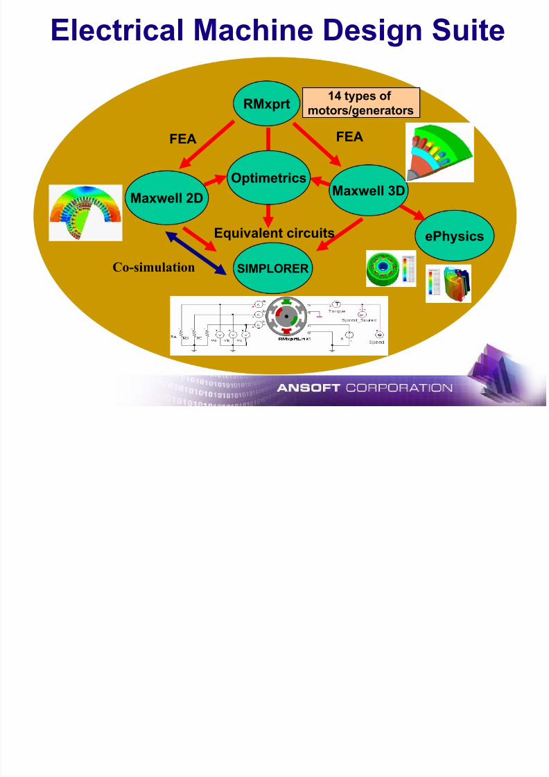
Electrical Machine Design Suite

7/16/2019 Motor Design Suite V12
http://slidepdf.com/reader/full/motor-design-suite-v12-5633856f5983f 2/60
Quick Introduction
Ansoft offers the most complete solution to electrical machine designin the industry through its Electrical Machine Design Suite
What is the Electrical Machine Design Suite?
Æ Five combinable tools which assist engineers in designing andanalyzing electrical machines
Æ Integrates electromagnetic, circuit, and system engineering usinga common desktop environment
The Electrical Machine Design Suite includes:
Æ RMxprt – for machine design
Æ Maxwell 2D/3D – for finite element analysis
Æ Optimetrics – for optimizationÆ Simplorer – for system analysis
Æ ePhysics – for thermal and stress analysis
7/16/2019 Motor Design Suite V12
http://slidepdf.com/reader/full/motor-design-suite-v12-5633856f5983f 3/60
Electrical Machine Design Suite
RMxprt
Maxwell 2DMaxwell 3D
SIMPLORER
14 types of
motors/generators
FEA FEA
Equivalent circuits
Co-simulation
ePhysics
Optimetrics

7/16/2019 Motor Design Suite V12
http://slidepdf.com/reader/full/motor-design-suite-v12-5633856f5983f 4/60
7/16/2019 Motor Design Suite V12
http://slidepdf.com/reader/full/motor-design-suite-v12-5633856f5983f 5/60
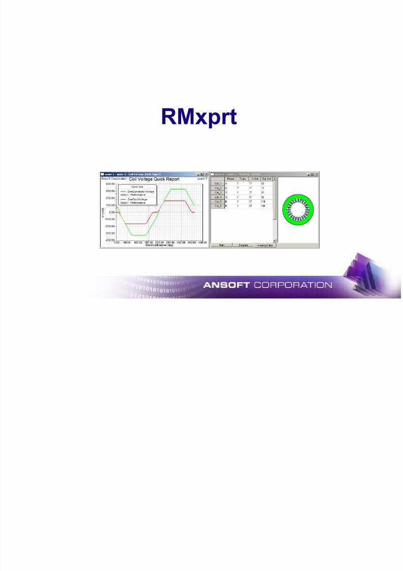
RMxprt

7/16/2019 Motor Design Suite V12
http://slidepdf.com/reader/full/motor-design-suite-v12-5633856f5983f 6/60
What is RMxprt ?• Analytical Design Software for Electric Machines• User can calculate machine performance, make material and size
decisions
• Flexible design and optimization process for rotating electric
machines which perform hundreds of "what if" analyses in a matter of seconds
Machine Types• Induction Machines : Three-Phase, Single-Phase
• Synchronous Machines : Line-Start PM, Adjustable Speed PM,
Salient Pole, Non-Salient Pole
• Brush commutated: DC, Permanent Magnet DC, Universal, Claw- pole Alternator
• Electronically commutated: Brushless PM, Switched Reluctance
7/16/2019 Motor Design Suite V12
http://slidepdf.com/reader/full/motor-design-suite-v12-5633856f5983f 7/60
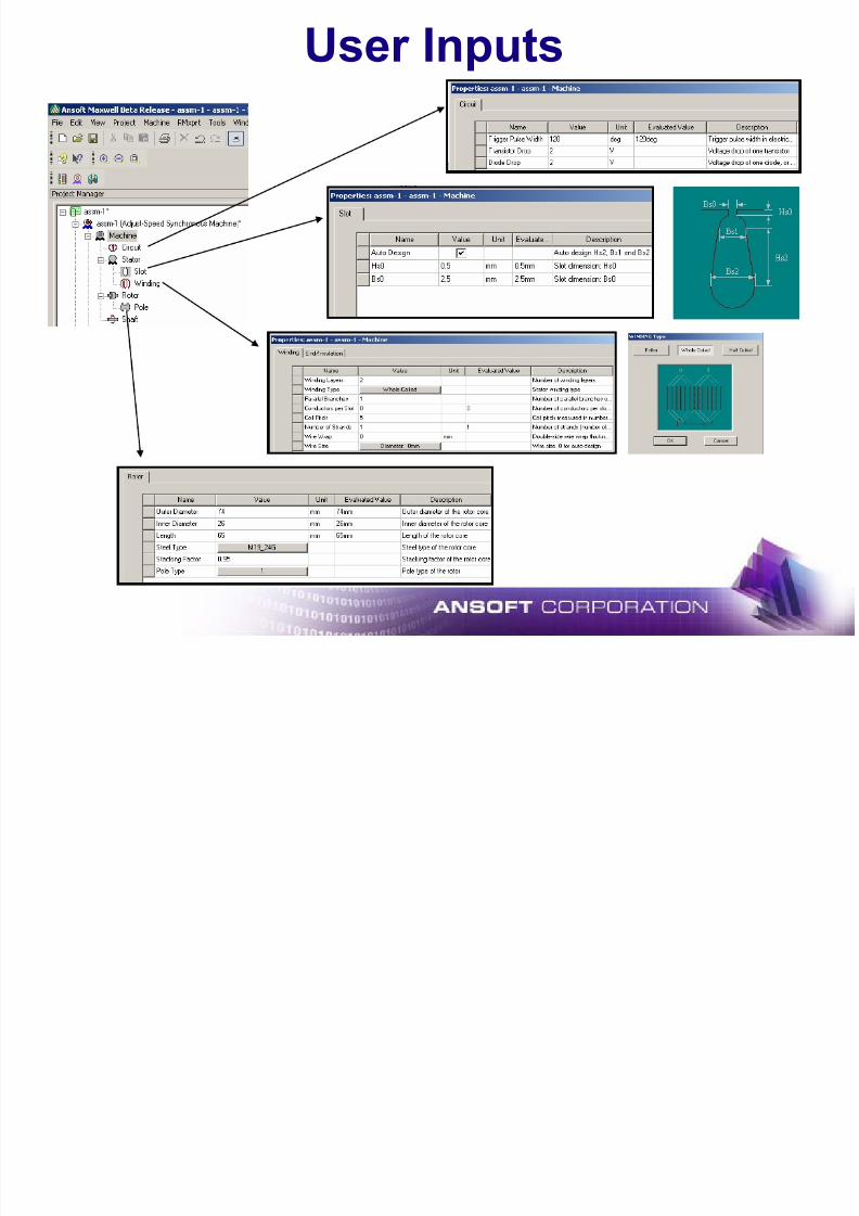
User Inputs

7/16/2019 Motor Design Suite V12
http://slidepdf.com/reader/full/motor-design-suite-v12-5633856f5983f 8/60
Typical Results
7/16/2019 Motor Design Suite V12
http://slidepdf.com/reader/full/motor-design-suite-v12-5633856f5983f 9/60
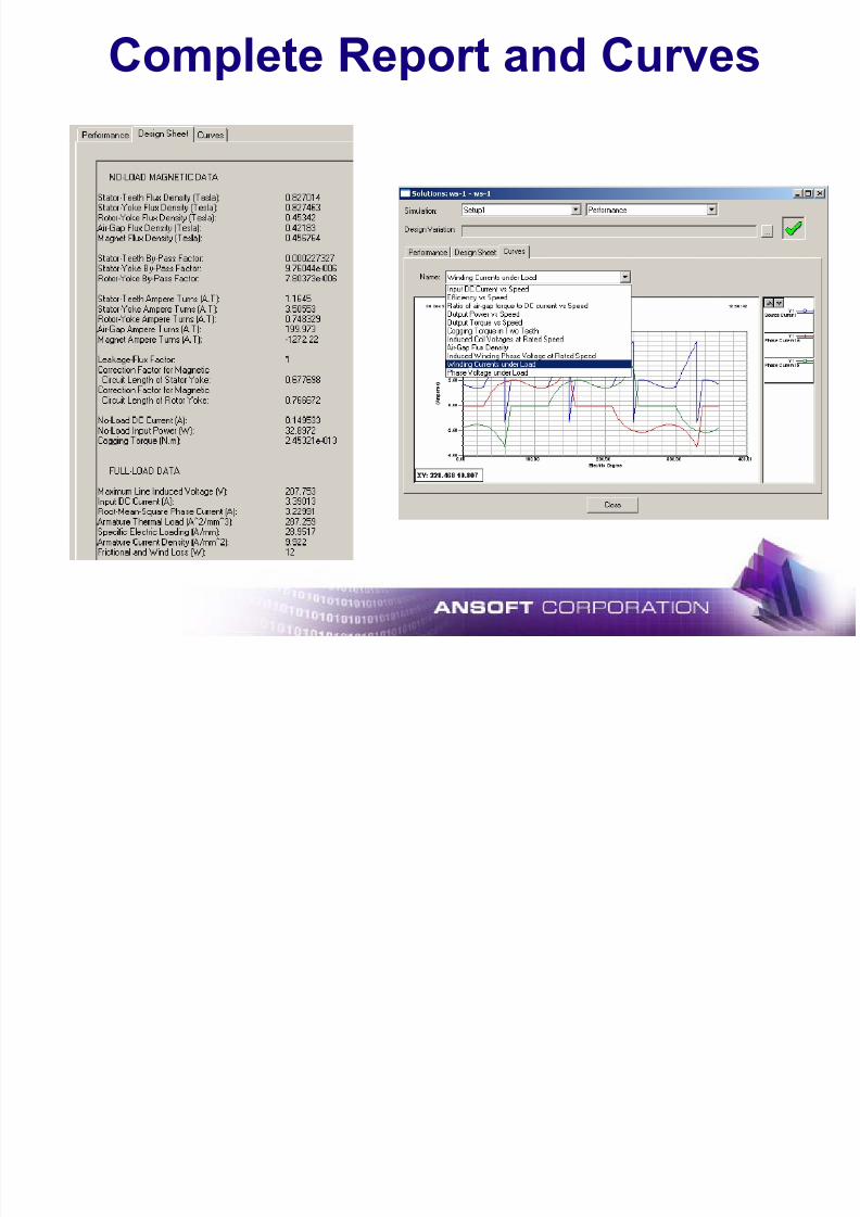
Complete Report and Curves
7/16/2019 Motor Design Suite V12
http://slidepdf.com/reader/full/motor-design-suite-v12-5633856f5983f 10/60
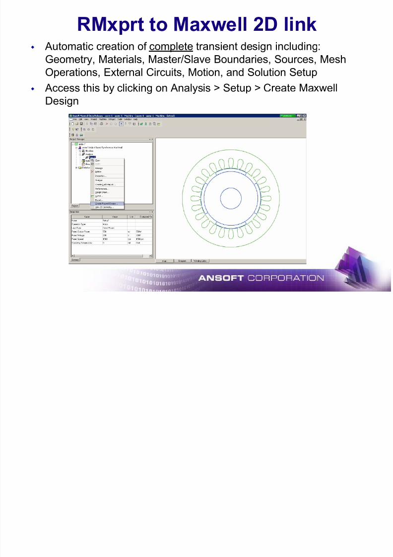
RMxprt to Maxwell 2D link
Automatic creation of complete transient design including:Geometry, Materials, Master/Slave Boundaries, Sources, Mesh
Operations, External Circuits, Motion, and Solution Setup
Access this by clicking on Analysis > Setup > Create Maxwell
Design

7/16/2019 Motor Design Suite V12
http://slidepdf.com/reader/full/motor-design-suite-v12-5633856f5983f 11/60
RMxprt to Maxwell 3D link
Complete geometry creation
One-click FEA design
Option for periodic or full
models Automatic update with project
variables
Geometry creation and materialassignment
General and dedicated machine
parts
Create new machine types with
arbitrary combinations
Dimension variables supported
7/16/2019 Motor Design Suite V12
http://slidepdf.com/reader/full/motor-design-suite-v12-5633856f5983f 12/60
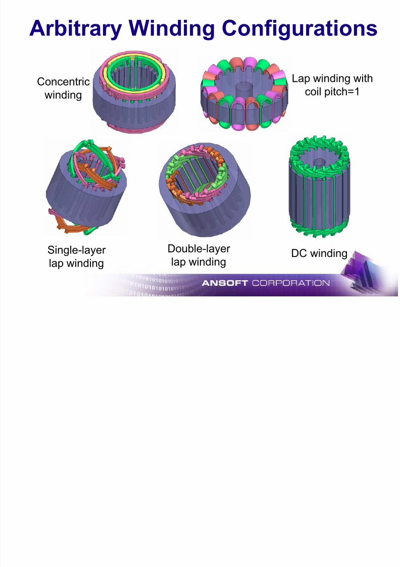
Arbitrary Winding Configurations
Lap winding with
coil pitch=1Concentric
winding
Double-layer
lap winding
Single-layer
lap windingDC winding

7/16/2019 Motor Design Suite V12
http://slidepdf.com/reader/full/motor-design-suite-v12-5633856f5983f 13/60
Common Slot Type Support
squirrel-cage cores
Single/double
squirrel-cage cores
Single/double
Inner/outer AC/DC
armature cores
Inner/outer AC/DC
armature cores
7/16/2019 Motor Design Suite V12
http://slidepdf.com/reader/full/motor-design-suite-v12-5633856f5983f 14/60
Maxwell
7/16/2019 Motor Design Suite V12
http://slidepdf.com/reader/full/motor-design-suite-v12-5633856f5983f 15/60
What is Maxwell?
Magnetic and Electric Finite Element Field Solvers
Static, Quasi-Static and Transient (time-domain)
solutions Linear and non-linear, isotropic and anisotropic, and
laminated materials
Parametric and Optimization capabilities includingstatistical, sensitivity and tuning analysis
Co-simulation with Simplorer
Direct link from RMxprt Direct link to ePhysics

7/16/2019 Motor Design Suite V12
http://slidepdf.com/reader/full/motor-design-suite-v12-5633856f5983f 16/60
Maxwell Desktop
Project
Manager Window
History
Tree
Window
3Dmodeler
Window
Message
Window
sixwindows
Properties
Window
ProgressWindow
7/16/2019 Motor Design Suite V12
http://slidepdf.com/reader/full/motor-design-suite-v12-5633856f5983f 17/60
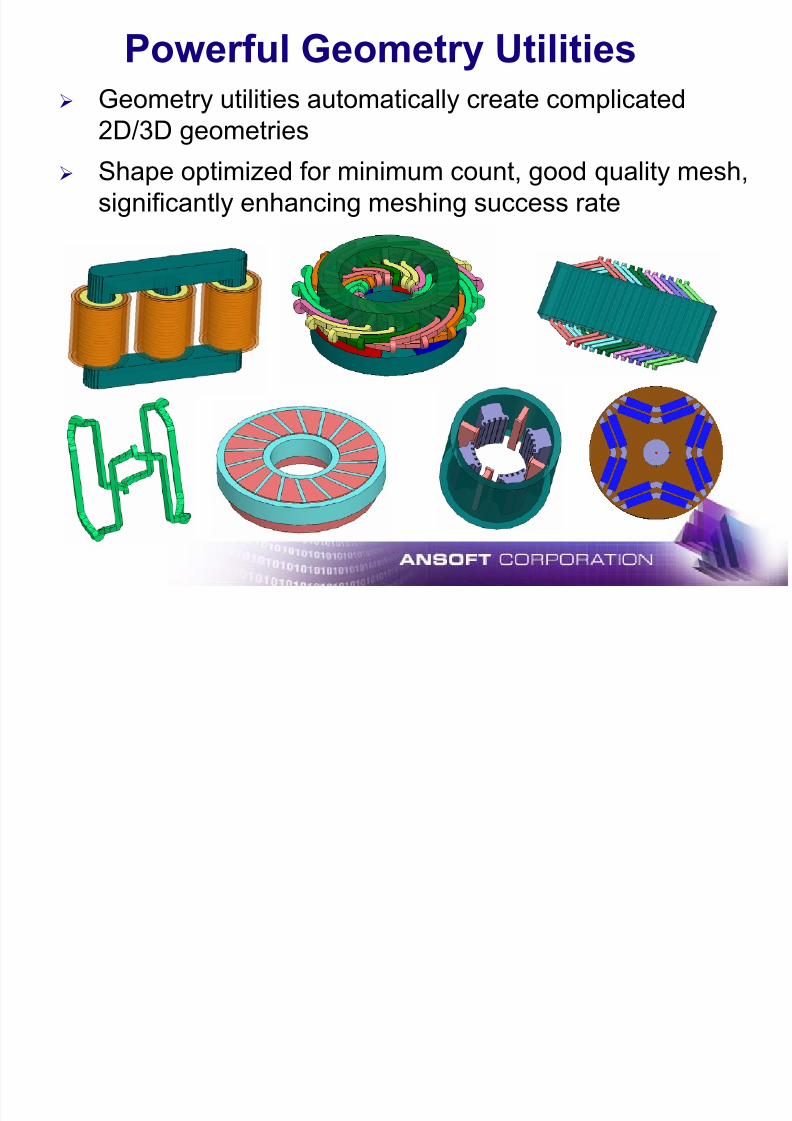
Powerful Geometry Utilities
¾ Geometry utilities automatically create complicated2D/3D geometries
¾ Shape optimized for minimum count, good quality mesh,
significantly enhancing meshing success rate
7/16/2019 Motor Design Suite V12
http://slidepdf.com/reader/full/motor-design-suite-v12-5633856f5983f 18/60
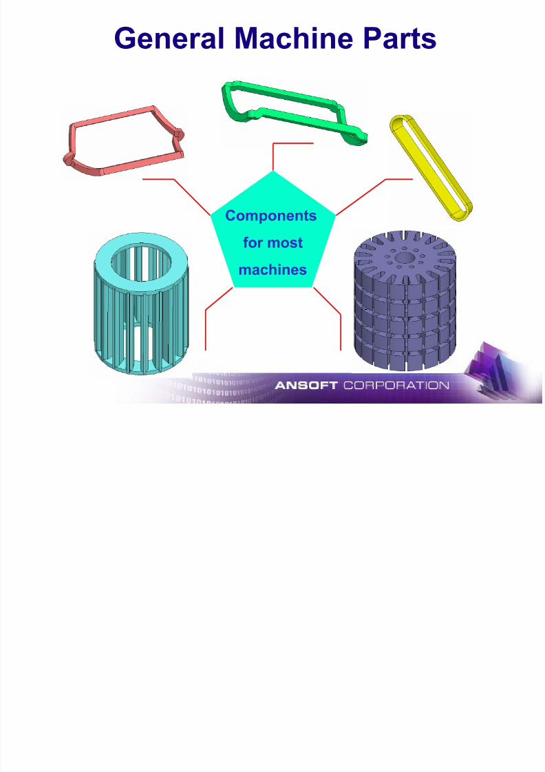
General Machine Parts
Components
for most
machines
7/16/2019 Motor Design Suite V12
http://slidepdf.com/reader/full/motor-design-suite-v12-5633856f5983f 19/60
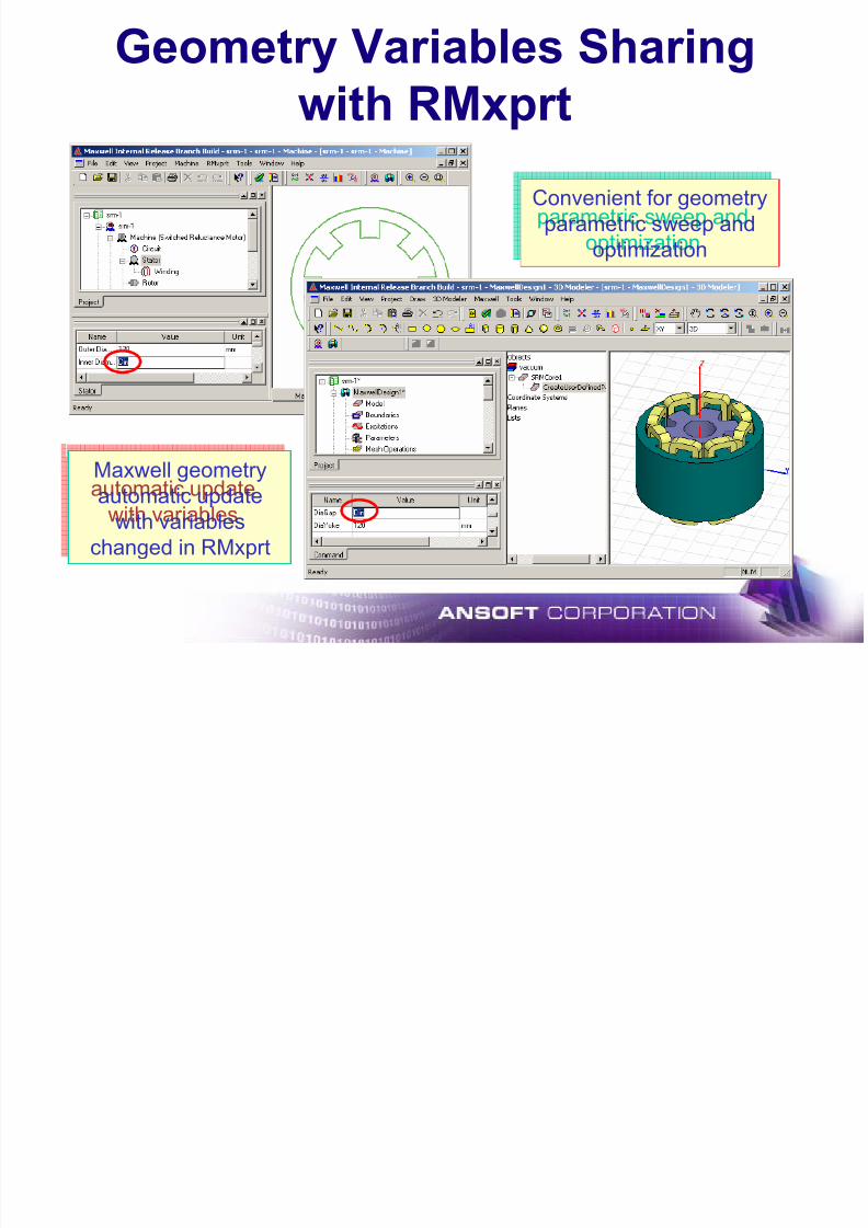
Geometry Variables Sharing
with RMxprt
Maxwell geometry
changed in RMxprt
Convenient for geometry
parametric sweep and
optimization
Convenient for geometry
parametric sweep andoptimization
automatic update
with variables
Maxwell geometry
automatic update
with variables
changed in RMxprt
7/16/2019 Motor Design Suite V12
http://slidepdf.com/reader/full/motor-design-suite-v12-5633856f5983f 20/60
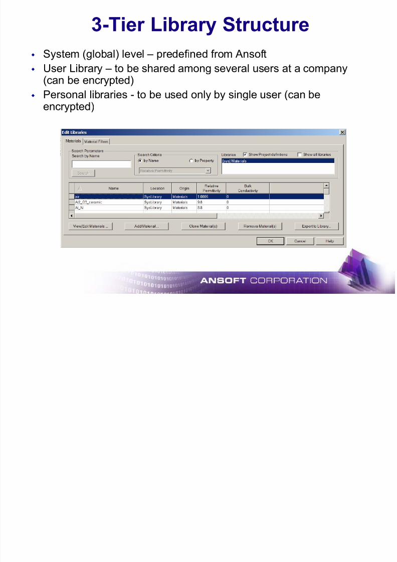
3-Tier Library Structure
System (global) level – predefined from Ansoft User Library – to be shared among several users at a company
(can be encrypted)
Personal libraries - to be used only by single user (can be
encrypted)
7/16/2019 Motor Design Suite V12
http://slidepdf.com/reader/full/motor-design-suite-v12-5633856f5983f 21/60
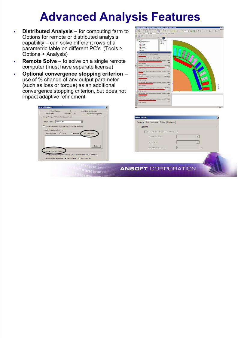
Advanced Analysis Features
Distributed Analysis – for computing farm toOptions for remote or distributed analysiscapability – can solve different rows of aparametric table on different PC’s (Tools >Options > Analysis)
Remote Solve – to solve on a single remotecomputer (must have separate license)
Optional convergence stopping criterion –use of % change of any output parameter (such as loss or torque) as an additionalconvergence stopping criterion, but does notimpact adaptive refinement

7/16/2019 Motor Design Suite V12
http://slidepdf.com/reader/full/motor-design-suite-v12-5633856f5983f 22/60
Double Rotor Motion
Rotor II
Rotor I
Stator
Two Bands in Transient Solver
For transient motion solver, two bands with two independently movingobjects now allowed
Both rotational and translational solvers can handle this

7/16/2019 Motor Design Suite V12
http://slidepdf.com/reader/full/motor-design-suite-v12-5633856f5983f 23/60
Multiple end connected conductors
Induction Motor with Dual Rotor Cages
squirrel cage I
squirrel cage II
For transient solver, can have for independently connected squirrelcage rotors
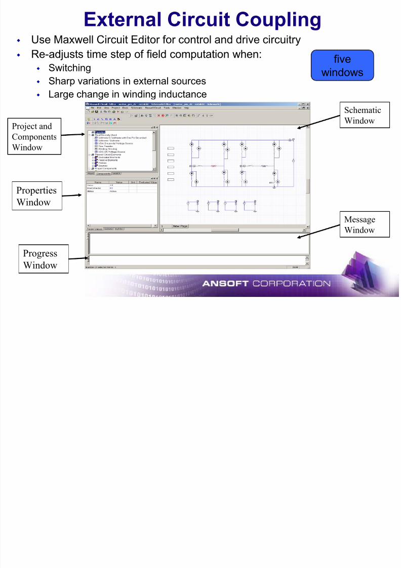
External Circuit Coupling
7/16/2019 Motor Design Suite V12
http://slidepdf.com/reader/full/motor-design-suite-v12-5633856f5983f 24/60
External Circuit Coupling Use Maxwell Circuit Editor for control and drive circuitry
Re-adjusts time step of field computation when: Switching
Sharp variations in external sources
Large change in winding inductance
fivewindows
Project and
Components
Window
Properties
Window
Schematic
Window
Message
Window
Progress
Window

7/16/2019 Motor Design Suite V12
http://slidepdf.com/reader/full/motor-design-suite-v12-5633856f5983f 25/60
Maxwell Co-simulation with Simplorer
¾ 2D transient co-simulation: Maxwell V12 – Simplorer V8
¾ Improved performance with asynchronous time steps
¾ Next step is to support 3D: Maxwell V12.x – Simplorer V8.x
Maxwell SIMPLORER
Lumped field
coupling parameters
Equivalent circuit
coupling parameters
7/16/2019 Motor Design Suite V12
http://slidepdf.com/reader/full/motor-design-suite-v12-5633856f5983f 26/60
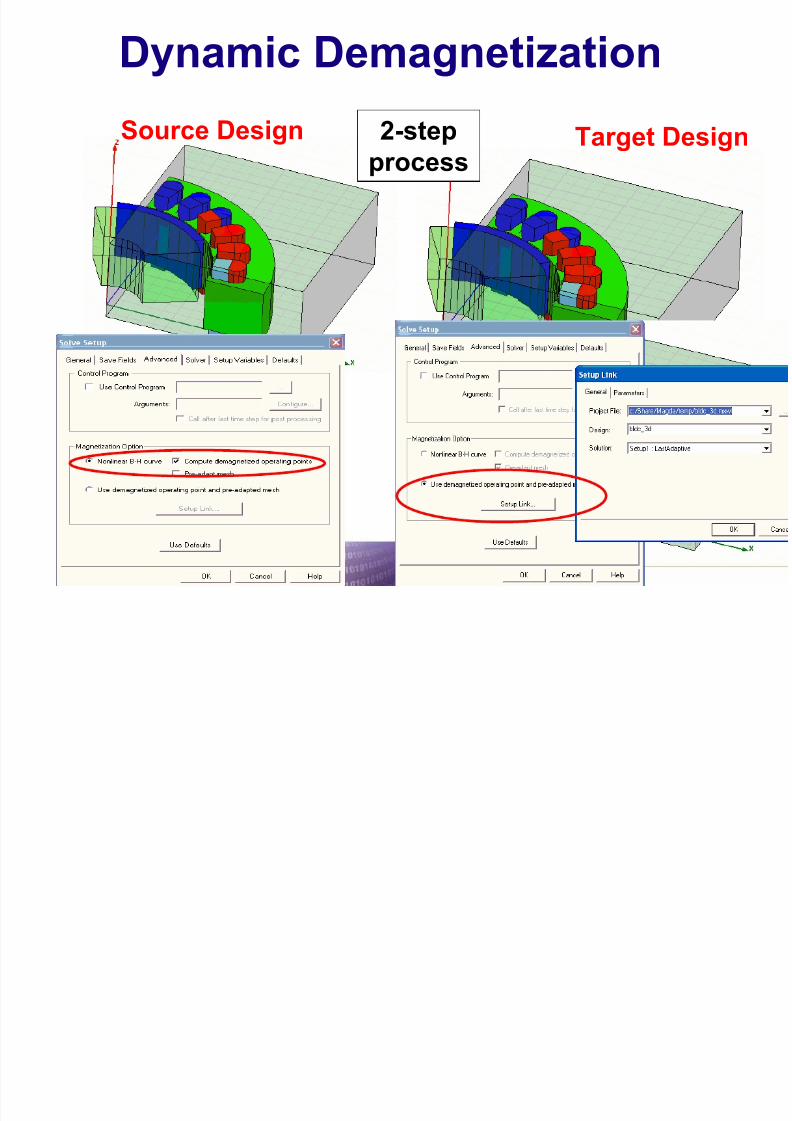
Dynamic Demagnetization
Source Design Target Design2-step
process

7/16/2019 Motor Design Suite V12
http://slidepdf.com/reader/full/motor-design-suite-v12-5633856f5983f 27/60
Dynamic Demagnetization - Results
Source H field
in the PM
Target H field
in the PM
Laminated Materials Core Loss
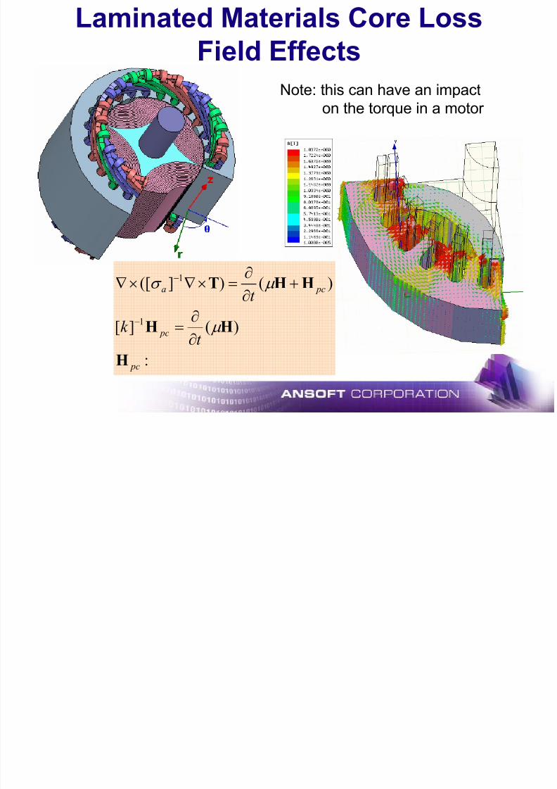
7/16/2019 Motor Design Suite V12
http://slidepdf.com/reader/full/motor-design-suite-v12-5633856f5983f 28/60
:
)(][
)()]([
1
1
pc
pc
pca
t k
t
H
HH
HHT
µ
µ σ
∂
∂=
+
∂
∂=×∇×∇
−
−
Laminated Materials Core Loss
Field Effects
Note: this can have an impact
on the torque in a motor
7/16/2019 Motor Design Suite V12
http://slidepdf.com/reader/full/motor-design-suite-v12-5633856f5983f 29/60
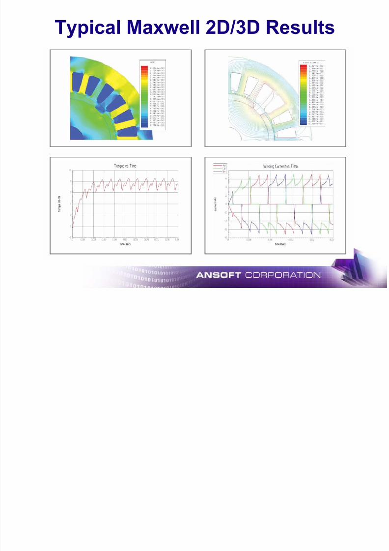
Typical Maxwell 2D/3D Results

7/16/2019 Motor Design Suite V12
http://slidepdf.com/reader/full/motor-design-suite-v12-5633856f5983f 30/60
Optimetrics
What is Optimetrics ?

7/16/2019 Motor Design Suite V12
http://slidepdf.com/reader/full/motor-design-suite-v12-5633856f5983f 31/60
What is Optimetrics ?
¾ Optimetrics enables engineers to determine the best design variationamong a model's possible variations.
¾ Create the original model, the nominal design, and then define design
parameters that vary
¾ Optimetrics includes five unique capabilities:
1. Parametrics: Define one or more variable sweep definitions, each specifying a series of variable
values within a range. Easily view and compare the results using plot or table to determine how each
design variation affects the performance of the design.
2.
Optimization: Identify the cost function and the optimization goal. Optimetrics automatically changesthe design parameter(s) to meet the goal. The cost function can be based on any solution quantity
that can be computes, such as field values, R,L,C force, torque, volume or weight.
3. Sensitivity: Determine the sensitivity of the design to small changes in variables in the vicinity of a
design point. Outputs include: Regression value at the current variable value, First derivative of the
regression, Second derivative of the regression
4. Tuning: Variable values are changed interactively and the performance of the design is monitored.
Useful after performing an optimization in which Optimetrics has determined an optimal variable
value, and you want to fine tune the value to see how the design results are affected.
5. Statistical: shows the distribution (Histogram) of a design output like force, torque or loss caused by
a statistical variation (Monte Carlo) of input variables.
Optimetrics Module (cont )

7/16/2019 Motor Design Suite V12
http://slidepdf.com/reader/full/motor-design-suite-v12-5633856f5983f 32/60
Optimetrics Module (cont.)
Distributed Parametrics and Optimization
Seamless setup Integrated with force,
torque, matrix
Complete support of Transient solution
Optimetrics Module (cont )
7/16/2019 Motor Design Suite V12
http://slidepdf.com/reader/full/motor-design-suite-v12-5633856f5983f 33/60
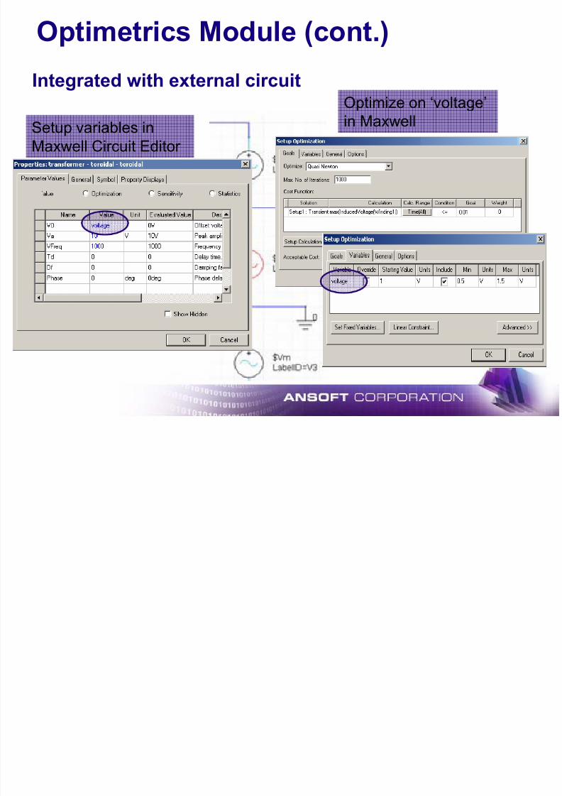
Optimetrics Module (cont.)
Integrated with external circuitOptimize on ‘voltage’
in MaxwellSetup variables in
Maxwell Circuit Editor
Optimetrics E ample
7/16/2019 Motor Design Suite V12
http://slidepdf.com/reader/full/motor-design-suite-v12-5633856f5983f 34/60
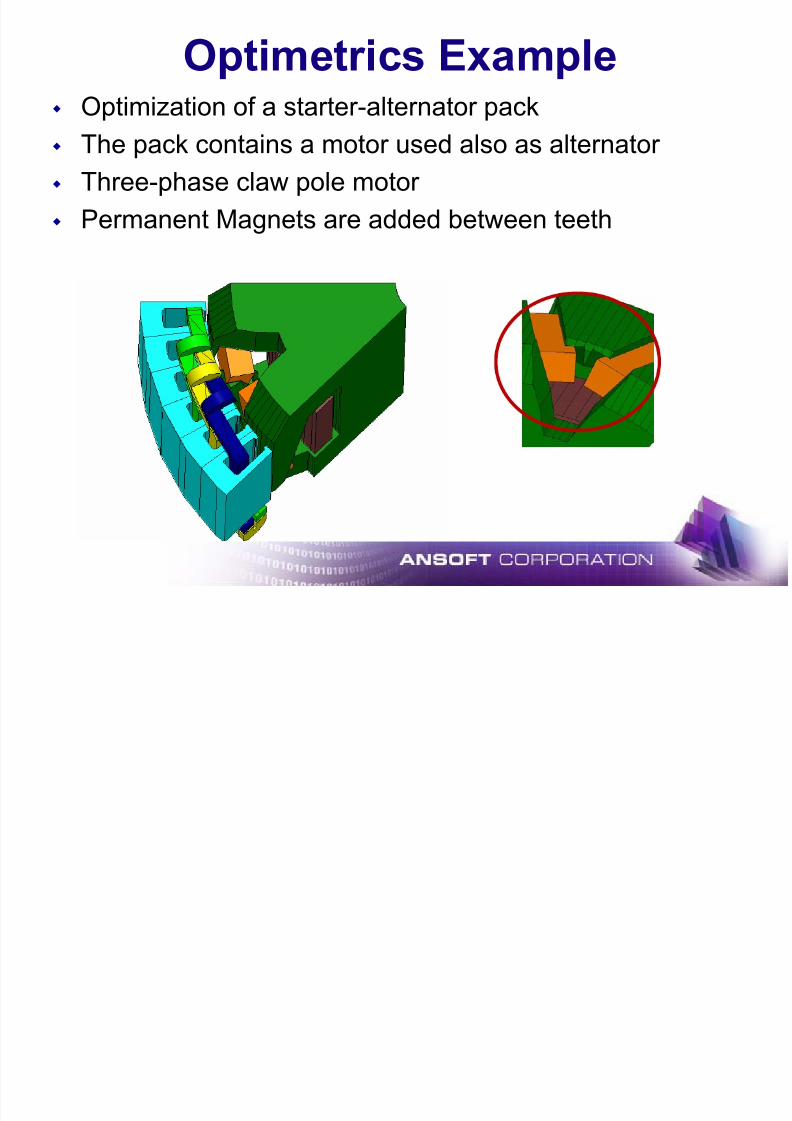
Optimetrics Example
Optimization of a starter-alternator pack The pack contains a motor used also as alternator
Three-phase claw pole motor
Permanent Magnets are added between teeth
Optimization of the Geometry
7/16/2019 Motor Design Suite V12
http://slidepdf.com/reader/full/motor-design-suite-v12-5633856f5983f 35/60
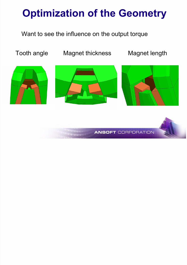
Optimization of the Geometry
Want to see the influence on the output torque
Tooth angle Magnet thickness Magnet length
R lt

7/16/2019 Motor Design Suite V12
http://slidepdf.com/reader/full/motor-design-suite-v12-5633856f5983f 36/60
Results
Transient analysis run for the optimized design
Initial Peak torque: 63.40 Nm
Optimized Peak Torque: 67.42 Nm
Initial Optimized
7/16/2019 Motor Design Suite V12
http://slidepdf.com/reader/full/motor-design-suite-v12-5633856f5983f 37/60
Simplorer
What is Simplorer ?

7/16/2019 Motor Design Suite V12
http://slidepdf.com/reader/full/motor-design-suite-v12-5633856f5983f 38/60
What is Simplorer ?
SUM2_6
CONST
id_ref
G(s)
GS2
I
I_PART_id
GAIN
idLIMIT
yd
UL := 9
LL := -9
GAIN
P_PART_id
KP := 0.76
12
R1 R2 R3 R450 1k 1k50
C1 C2
3.3u
3.3u
V0 := 5 V0 := 0
N0005
N0003N0004
N0002
Circuits
Block
Diagrams
State
Machines
• Multi-domain, system simulator for designing high performance systems
• Commonly used by the automotive,
aerospace/defense, and industrial
automation industries.• Integrated analysis with electromagnetic
simulation tools (Maxwell, PExprt, RMxprt,
Q3D, HFSS)
• Three Basic Simulation Engines:9 Circuits
9 Block Diagrams
9 State Machines
• Analysis Types: DC, AC, Transient• Co-simulation with Maxwell and Simulink
• Statistical Analysis and Optimization
• VHDL-AMS Capability
IMP = 0
IMP = 1IMP = 0
IMP = 1
IMP = 0 and RLine.I <= ILOW
IMP = 1 and RLine.I >= IUP
IMP = 0 and RLine.I >= IUP
IMP = 1 and RLine.I <= ILOW
SET: CS1:=-1
SET: CS2:=-1SET: CS3:=-1
SET: CS4:=-1
SET: CS1:=-1
SET: CS2:=1SET: CS3:=-1
SET: CS4:=-1
SET: CS1:=1
SET: CS2:=-1SET: CS3:=-1
SET: CS4:=-1
SET: CS1:=-1
SET: CS2:=-1SET: CS3:=-1
SET: CS4:=-1
C l t S t D i
7/16/2019 Motor Design Suite V12
http://slidepdf.com/reader/full/motor-design-suite-v12-5633856f5983f 39/60
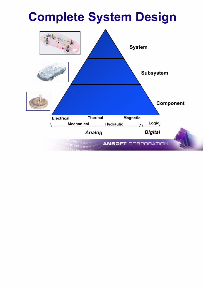
Complete System Design
ThermalElectrical
Mechanical Hydraulic
Magnetic
Logic
Analog Digital
Component
Subsystem
System
SIMPLORER Methodology
7/16/2019 Motor Design Suite V12
http://slidepdf.com/reader/full/motor-design-suite-v12-5633856f5983f 40/60
SIMPLORER Methodology
Electrical/Electronics(analog and digital circuits)
Digital Control Systems(state machine)
12
R1 R2 R3 R450
1k 1k50
C1 C2
3.3u
3.3u
V0 := 5 V0 := 0
N0005
N0003 N0004
N0002
C14.7m
MS3 ~
B A C
IGBT1 IGBT2 IGBT3
IGBT4 IGBT5 IGBT6
XOR
XOR2_DEL1
XOR
XOR2_DEL2
AND
AND2_DEL1
AND
AND2_DEL2 OR
OR2_DEL1
SUM
Carry
IMP = 0
IMP = 1IMP = 0
IMP = 1
IMP = 0 and RLine.I <= ILOW
IMP = 1 and RLine.I >= IUP
IMP = 0 and RLine.I >= IUP
IMP = 1 and RLine.I <= ILOW
SET: CS1:=-1SET: CS2:=-1
SET: CS3:=-1SET: CS4:=-1
SET: CS1:=-1SET: CS2:=1SET: CS3:=-1SET: CS4:=-1
SET: CS1:=1SET: CS2:=-1SET: CS3:=-1SET: CS4:=-1
SET: CS1:=-1SET: CS2:=-1SET: CS3:=-1SET: CS4:=-1
A
B
C
Analog Control, Mechanics
(block diagram)
SUM2_6
CONST
id_ref
G(s)
GS2
I
I_PART_id
GAIN
idLIMIT
yd
UL := 9
LL := -9
GAIN
P_PART_id
KP := 0.76
Each part of a complex technical
system is represented by the most
appropriate modeling language
Multi Domain Design

7/16/2019 Motor Design Suite V12
http://slidepdf.com/reader/full/motor-design-suite-v12-5633856f5983f 41/60
Multi Domain Design
Power Converter
Electro Mechanics
Sensors
Transformer
Control
Multitude of Domains
Multitude of Tools & Methods
MechanicsUtility
Simulator Coupling Technology

7/16/2019 Motor Design Suite V12
http://slidepdf.com/reader/full/motor-design-suite-v12-5633856f5983f 42/60
Simulator Coupling Technology
SimulinkMaxwell2D/3D
Electromagnetism
Electro mechanics
SIMPLORER Simulation Data Bus
Simulator Coupling Technology
MathCadC/C++
Interface
Circuit
Simulator
Block Diagram
Simulator
State Machine
Simulator VHDL-AMS
Simulator
Model Database
Electrical, Blocks, States, Machines, Automotive, Hydraulic,
Mechanics, Power, Semiconductors…
Integrated Design Environment
7/16/2019 Motor Design Suite V12
http://slidepdf.com/reader/full/motor-design-suite-v12-5633856f5983f 43/60
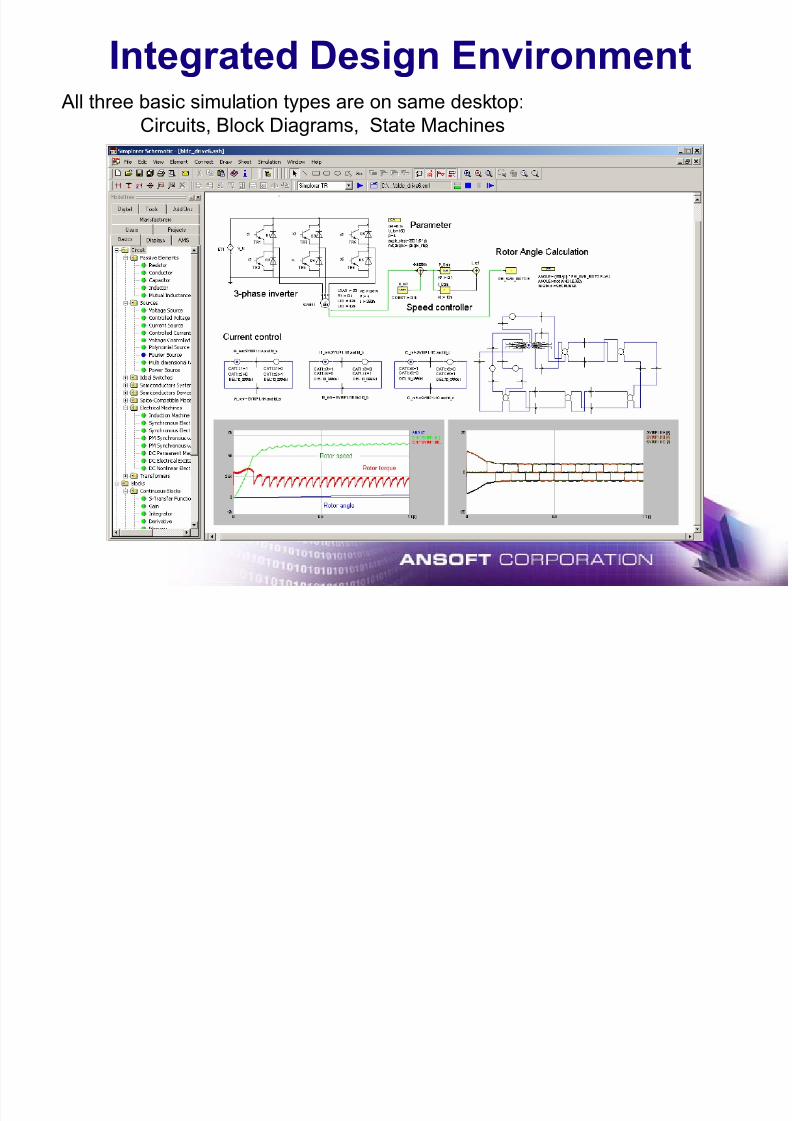
Integrated Design Environment All three basic simulation types are on same desktop:
Circuits, Block Diagrams, State Machines
Power Library

7/16/2019 Motor Design Suite V12
http://slidepdf.com/reader/full/motor-design-suite-v12-5633856f5983f 44/60
Power Library
Power System and Cable Models
Single Phase Power Supply
Ideal Three Phase Power Supply
Three Phase Power Supply with Impedance
WIRE - Gamma Model
Wire T-Model
Inverter Topologies
Line-commutated Converters
B2 Diode Bridge
B2 Fully Controlled
B2 Half-Controlled, Symmetrical
B2 Half-Controlled, Asymmetrical
B6 Diode Bridge
Two Level Inverter Equivalent Circuit
Three Phase Two Level Inverter
Single Phase Two Level Inverter
Three Phase Three Level Inverter
Single Phase Three Level Inverter
Control Algorithms
Two Level Square Wave
Two Level Natural Sampling
Three Level Single Phase
Three Level Three Phase
Load Models
Three Level Single Phase NS
Three Level Three Phase NSFour Quadrant Current Control
Four Quadrant Natural Sampling
B6 Thyristor Bridge
B6 Bridges - Inverse Parallel ConnectionB12 Diode Bridge
B12 Thyristor Bridge Parallel Connection
B12 Thyristor Bridge Cascade
B24 Thyristor Bridge
Single Phase A.C. Chopper
Three Phase A.C. Chopper
DC Link
Three Phase RL Load
Logic
Dead Time
Power Library
Applications:• AC/DC Converters
• Inverters (DC/AC)
• Drive Systems
• Power Quality
• Alternative Power
Industries:
• Industrial Automation
• Drives Manufacturers
• EV/EHV
• Power Conversion• Power Quality
+ Battery and Fuel Cell
Mechanical Elements Library

7/16/2019 Motor Design Suite V12
http://slidepdf.com/reader/full/motor-design-suite-v12-5633856f5983f 45/60
Mechanical Elements Library
Rotational
Mass
Translational
Mass
Coordinate Transformation
Rotational-Rotational
Rotational-Translational
Translational-Rotational
SYMP Synchronous Machine Permanent Excitation
SYMP Synchronous Machine Permanent Excitation w Damper
Electrical MachinesDCMP DC-Machine Permanent Excitation
ASMS Slip Ring Induction Machine
Rigidity
Rigidity
Torque Source
Ground
Angular Velocity Source
Velocity Source
Ground
Force Source
Translational-Translational
Mechanical Systems
Applications:
• Drive Trains
• Electro-HydraulicSystems
• Electro-MechanicalSystems
• Load Variations
Industries:
• Automotive Suppliers
• Drive Manufacturers
• Industrial Automation• Defense
• Aerospace
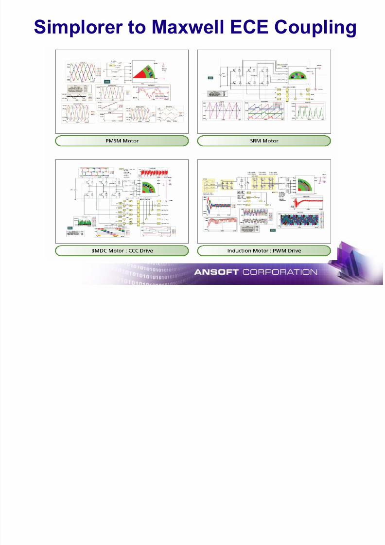
Simplorer to Maxwell ECE Coupling
7/16/2019 Motor Design Suite V12
http://slidepdf.com/reader/full/motor-design-suite-v12-5633856f5983f 46/60
Simplorer to Maxwell ECE Coupling
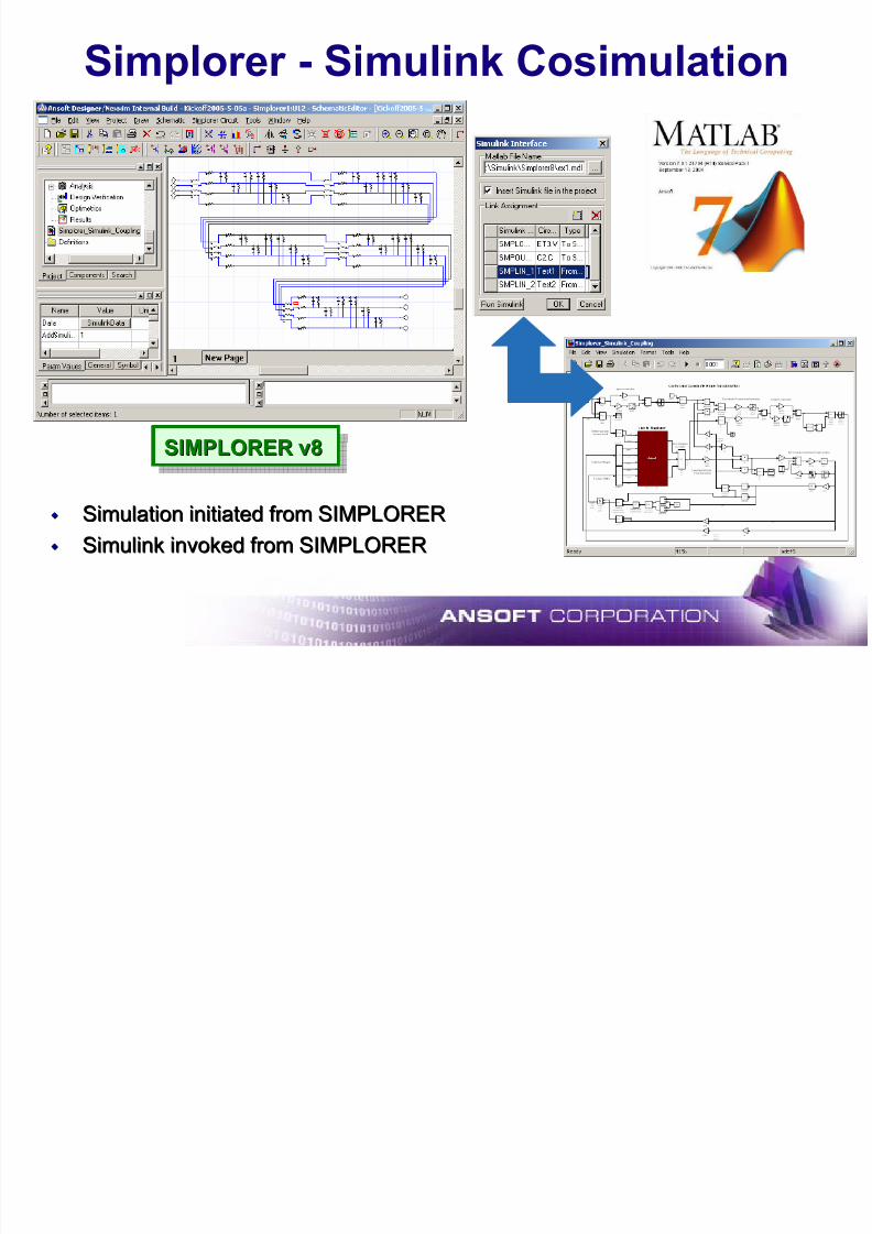
Simplorer - Simulink Cosimulation
7/16/2019 Motor Design Suite V12
http://slidepdf.com/reader/full/motor-design-suite-v12-5633856f5983f 47/60
Simplorer Simulink Cosimulation
SIMPLORER v8
SIMPLORER v8SIMPLORER v8
Simulation initiated from SIMPLORERSimulation initiated from SIMPLORER
SimulinkSimulink invoked from SIMPLORERinvoked from SIMPLORER
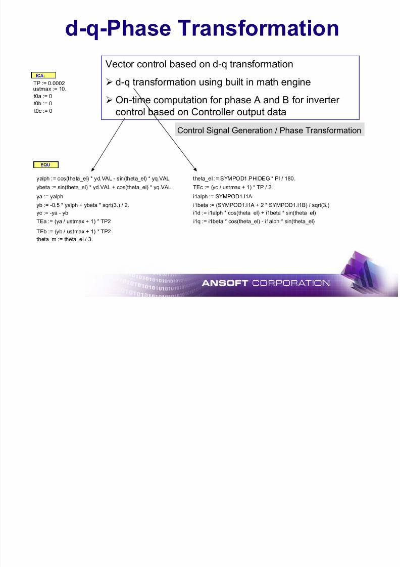
d-q-Phase Transformation
7/16/2019 Motor Design Suite V12
http://slidepdf.com/reader/full/motor-design-suite-v12-5633856f5983f 48/60
d q Phase Transformation
Control Signal Generation / Phase Transformation
Vector control based on d-q transformation
¾ d-q transformation using built in math engine
¾On-time computation for phase A and B for inverter
control based on Controller output data
ICA:
TP := 0.0002ustmax := 10.
t0a := 0
t0b := 0
t0c := 0
EQU
yalph := cos(theta_el) * yd.VAL - sin(theta_el) * yq.VAL theta_el := SYMPOD1.PHIDEG * PI / 180.
ybeta := sin(theta_el) * yd.VAL + cos(theta_el) * yq.VAL TEc := (yc / ustmax + 1) * TP / 2.
ya := yalph i1alph := SYMPOD1.I1A
yb := -0.5 * yalph + ybeta * sqrt(3.) / 2. i1beta := (SYMPOD1.I1A + 2 * SYMPOD1.I1B) / sqrt(3.)
yc := -ya - yb i1d := i1alph * cos(theta_el) + i1beta * sin(theta_el)TEa := (ya / ustmax + 1) * TP2 i1q := i1beta * cos(theta_el) - i1alph * sin(theta_el)
TEb := (yb / ustmax + 1) * TP2
theta_m := theta_el / 3.
Speed and Torque Control

7/16/2019 Motor Design Suite V12
http://slidepdf.com/reader/full/motor-design-suite-v12-5633856f5983f 49/60
Speed and Torque Control
Speed ControlI_nI_iq n
GAIN
GAIN Y t
GAIN
id
I
KI := 29.02k
UL := 10
LL := -10
GAIN
P_PART_n
KP := 0.1161k
Controller design using block
diagrams
¾ Speed Profile from Data
File
¾Reference Torque
Determination
ust_in
GAIN iq
ust
d-q-Current Controller
I
G ( s ) GS1
UL := 9
m_ref LL := -9 P_Iq
G(s)
GS2
I
I_id
LIMIT GAIN LIMIT
yq KP := 0.76
id_ref
CONST
KI := 80
yd P_id
LIMIT GAIN
UL := 9 KP := 0.76LL := -9
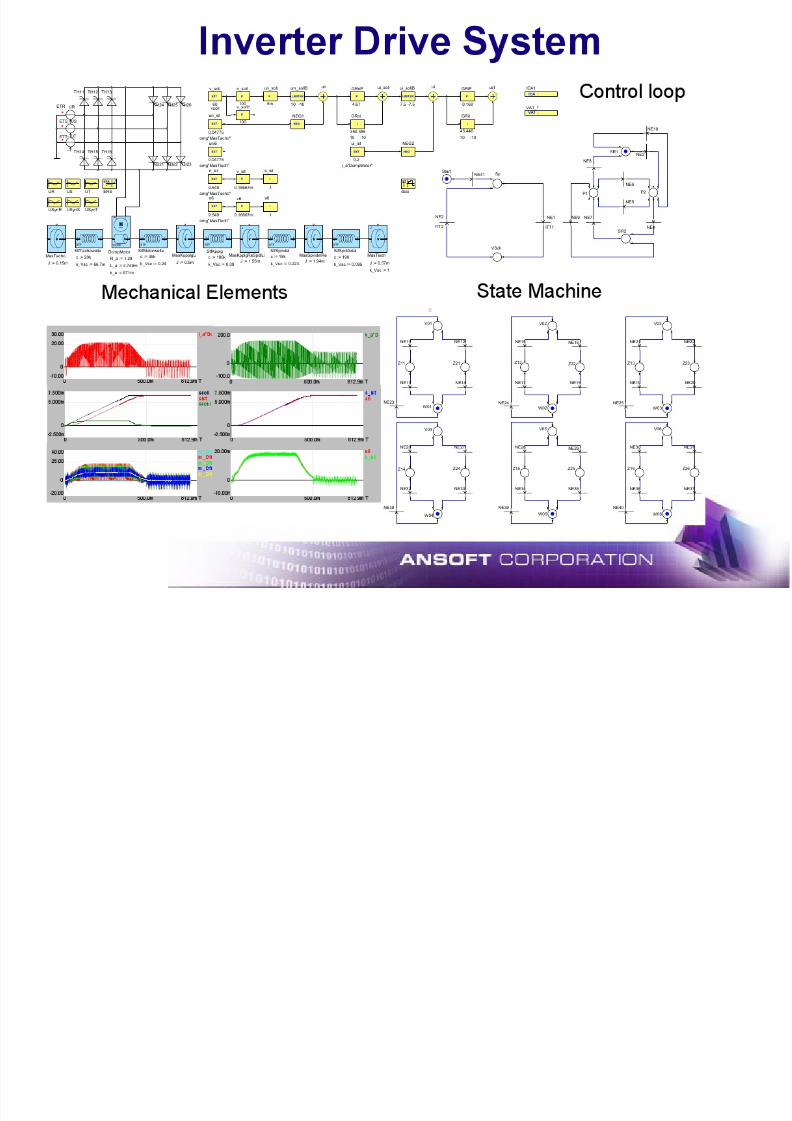
DC Motor Drive System

7/16/2019 Motor Design Suite V12
http://slidepdf.com/reader/full/motor-design-suite-v12-5633856f5983f 50/60
y
L_R
L_S
L_T
ET1
ET2
ET3
CD
1m
R_R
R_S
R_T
YtLOAD
CONTR_OUT
THRES2 := 2.5
VAL2 := 1
THRES1 := -2.5
VAL1 := -1
-16.66m
DCM.N P_GAIN
KP := 50
I_GAIN
KI := 20
LIMITER
UL := 20
LL := 0
10m
GAIN GAIN
I
LIMIT
CONST
N_REF
16.6667
0.3mM
DCM
RA := 1.2
LA := 9.5m
KE := 0.544
J := 4m
A
+ AM1D1 D2 D3
D4 D5 D6
D7
TR
CONST
CLOCK
.1m
0 50.00mT
15.00
0 0
10.00
0
0
100.00m
100.00m
50.00m
50.00m
Motor torque and
load torque
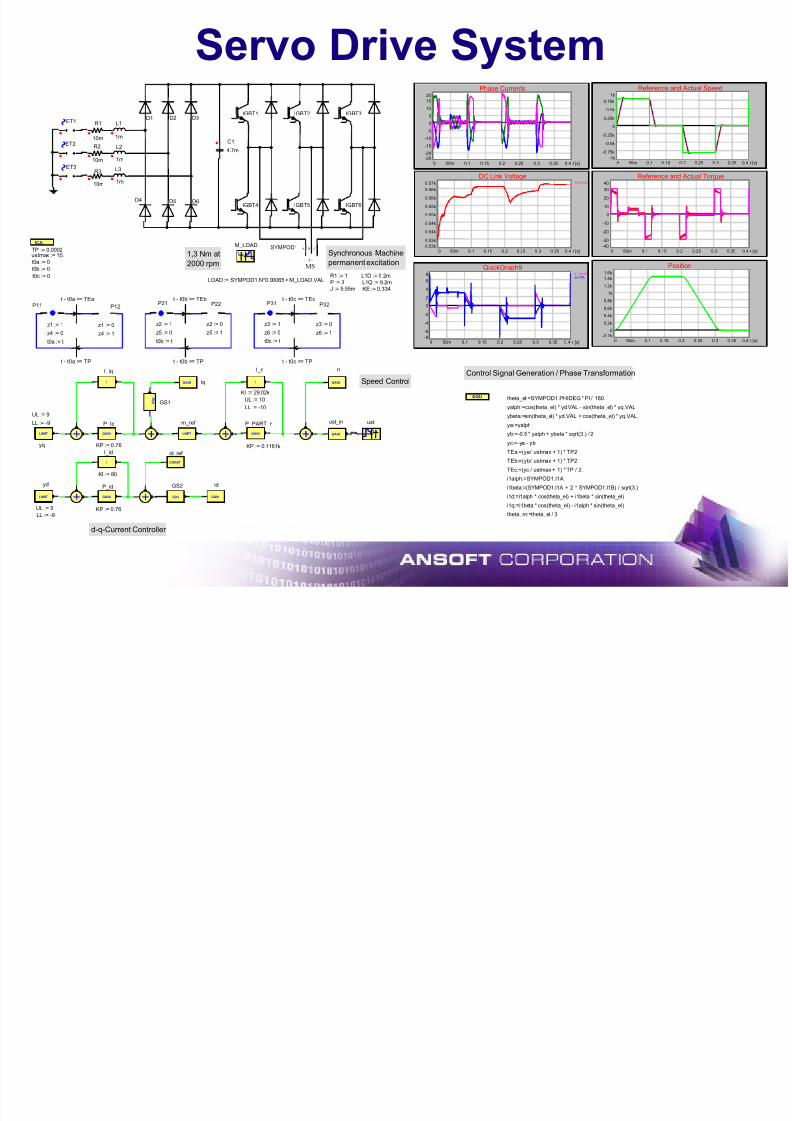
Servo Drive System
7/16/2019 Motor Design Suite V12
http://slidepdf.com/reader/full/motor-design-suite-v12-5633856f5983f 51/60
ET1
ET2
ET3
R1
R2
R3
L1
L2
L3
10m
10m
10m
1m
1m
1m
D1 D2 D3
D4 D5 D6
C1
4.7m
ICA:
EQU
TP := 0.0002ustmax := 10.
GAIN
n
GAIN
ust_in
GAIN iq
Y tust
d-q-Current Controller
Speed Control
1,3 Nm at
2000 rpm
Yt
M_LOAD
MS3 ~
BA CSYMPOD1
R1 := 1 L1D := 9.2m
L1Q := 9.2m
KE := 0.334
P := 3J := 5.55m
LOAD := SYMPOD1.N*0.00065 + M_LOAD.VAL
t0a := 0
t0b := 0
t0c := 0
Synchronous Machine
permanent excitation
Control Signal Generation / Phase Transformation
Phase Currents
t [s]
20
-25
0
-20
-15
-10
-5
5
10
15
0 0.450m 0.1 0.15 0.2 0.25 0.3 0.35
Reference and Actual Speed
t [s]
1k
-1k
0
-0.75k
-0.5k
-0.25k
0.25k
0.5k
0.75k
0 0.450m 0.1 0.15 0.2 0.25 0.3 0.35
DC Link VoltageC1.V [V]
t [s]
0.57k
0.53k
0.53k
0.54k
0.54k
0.55k
0.55k
0.56k
0.56k
0 0.450m 0.1 0.15 0.2 0.25 0.3 0.35
Position
t [s]
1.6k
-0.2k0
0.2k
0.4k
0.6k
0.8k
1k
1.2k
1.4k
0 0.450m 0.1 0.15 0.2 0.25 0.3 0.35
Reference and Actual Torque
t [s]
40
-40
0
-30
-20
-10
10
20
30
0 0.450m 0.1 0.15 0.2 0.25 0.3 0.35
QuickGraph92 * yd.VALyq.VAL
t [s]
8
-8
0
-6
-4
-2
2
4
6
0 0.450m 0.1 0.15 0.2 0.25 0.3 0.35
G(s)
GS2
I
I_id
GAIN
id
LIMIT
yq
UL := 9
LL := -9
LIMIT
yd
UL := 9
LL := -9
GAIN
P_id
KP := 0.76
P21
z2 := 1
z5 := 0
P22
z2 := 0
z5 := 1
t - t0b >= TP
t - t0b >= TEb
t0b := t
P11
z1 := 1
z4 := 0
t0a := t
P12
z1 := 0
z4 := 1
P31
z3 := 1
z6 := 0
t0c := t
P32
z3 := 0
z6 := 1
t - t0c >= TP
t - t0c >= TEct - t0a >= TEa
t - t0a >= TP
G ( s ) GS1
I
I_iq
I
I_n
KI := 29.02k
UL := 10
LL := -10
GAIN
P_PART_nLIMIT
m_ref
KP := 0.1161k
IGBT1 IGBT2 IGBT3
IGBT4 IGBT5 IGBT6
CONST
id_ref
KI := 80
GAIN
P_Iq
KP := 0.76
theta_el:=SYMPOD1.PHIDEG * PI / 180.
yalph:=cos(theta_el) * yd.VAL - sin(theta_el) * yq.VAL
ybeta:=sin(theta_el) * yd.VAL + cos(theta_el) * yq.VAL
ya:=yalph
yb:=-0.5 * yalph + ybeta * sqrt(3.) / 2.
yc:=-ya - yb
TEa:=(ya/ ustmax + 1) * TP2
TEb:=(yb/ ustmax + 1) * TP2
TEc:=(yc / ustmax + 1) * TP / 2.
i1alph:=SYMPOD1.I1A
i1beta:=(SYMPOD1.I1A + 2 * SYMPOD1.I1B) / sqrt(3.)
i1d:=i1alph * cos(theta_el) + i1beta * sin(theta_el)
i1q:=i1beta * cos(theta_el) - i1alph * sin(theta_el)
theta_m:=theta_el / 3.
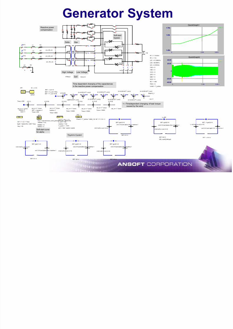
Generator System
7/16/2019 Motor Design Suite V12
http://slidepdf.com/reader/full/motor-design-suite-v12-5633856f5983f 52/60
+
V
+
V
+
V
A+
A+
A+ +
V
+
V
+
V
+
V
+
V
+
V
R1
R2
R3
L1
L2
L3
R4
1n
L4
1n
ET1
ET2
ET3
TH1
TH2
TH3
TH4
vm22 vm11vm33
TH5
TH6
vm_HS_U1
vm_HS_U2
vm_HS_U3
IGAIN
alpha2
KI := -0.1k
bypass:=0
Tmax:=-500
net_in:=1 * Unom
main:=1
bypass:=1
Tmax:=-5000
net_in:=1 * Unom
Tmax:=-10000
net_in:=1 * Unom net_in:=1 * Unom
Tmax:=-15000Tmax:=-19000
net_in:=1 * Unomnet_in:=1 * Unom
(t>=0.6) (t>=2.5) (t>=3.5) (t>=4.5) (t>=4.8)
SET: := con:=0
(t>=0.65) State10_3
con:=1
net_in:=1 * Unom
Tmax:=-500
SET: := bypass:=1
(t>0.1)
soft
con:=1(t>=(0.65+T_con))
(t>=(0.65+(2*T_con)))
(t>=(0.65+(3*T_con)))
(t>=(0.65+(4*T_con)))(t>=(0.65+(6*T_con)))
(t>=(0.65+(5*T_con))) (t>=(0.65+(7*T_con)))
(t>=(0.65+(8*T_con)))
SET: ignit11:=0
vm1.V>0 and alpha.VAL<=risetime-1
t>th1+toff or vm1.V<=0
SET: ignit12:=0
SET: th1:=t
vm1.V<0 and alpha.VAL<= risetime-1
t>th1+toff or vm1.V>=0
SET: ignit31:=0
SET: th3:=t
vm3.V>0 and alpha.VAL<=risetime-1
t>th3+toff or vm3.V<=0
SET: := ignit32:=0
SET: := th3:=t
vm3.V<0 and alpha.VAL <= risetime-1
t > th3+toff or vm3.V>=0
SET: ignit21:=0
SET: th2:=t
vm2.V>0 and alpha.VAL<=risetime-1
t>th2+toff or vm2.V<=0
n_off2
SET: ignit22:=0
vm2.V<0 and alpha.VAL<=risetime-1
t>th2+toff or vm2.V>=0
EQU Yt ICA: EQU
tignit := alpha.VAL/ (360 * freq)
freq := 50
toff := 1 / (2.1 * freq)
alpha
risetime := 120
C_com:= 10u
Unom:= 20k / 1.73
T_turbine:= -5000
VA2_1
Pmech := T_turbine * ASM_1.N / 60 * 2 * 3.14 / 3
Star
High Voltage Low Voltage
Dy5 TFR3LP1TFR3LS1
am1 := 20k * sqrt(2) / sqrt(3)
FILE := asynchronous_wind_generator5_ssh__alpha.mdx
TPERIO := 0.5
PHASE := 0PERIO := 0
Delta
M3 ~ B
A
C
R1 := 1.13333m
R2 := 1.7m
LS1 := 0.135667m
LS2 := 84.6667u
LM := 4.33333m
I1A0 := 0
I1B0 := 0
I1C0 := 0
I2A0 := 0
I2B0 := 0
I2C0 := 0
N0 := 1.49k
PHI0 := 0
LOAD := T_turbine
Reactive power
compensation
Soft start
bypass
Soft start curve
for alpha
<---Timedependent changing of load torque
caused by the wind
Thyristor Control
SET: := C_con:=100u
SET: := T_con:=0.05
Time dependent changing of the capacitances
in the reactive power compensation
QuickGraph1 ASM_1.N
t
1.70k
1.40k
1.60k
0 3.002.00
QuickGraph2vm1.Vvm2.Vvm3.V
t
40.00
-40.00
0
-25.00
25.00
0 3.002.00
SET: th1:=t
SET: th2:=t
DEL: ignit22 ## tignit
7/16/2019 Motor Design Suite V12
http://slidepdf.com/reader/full/motor-design-suite-v12-5633856f5983f 53/60
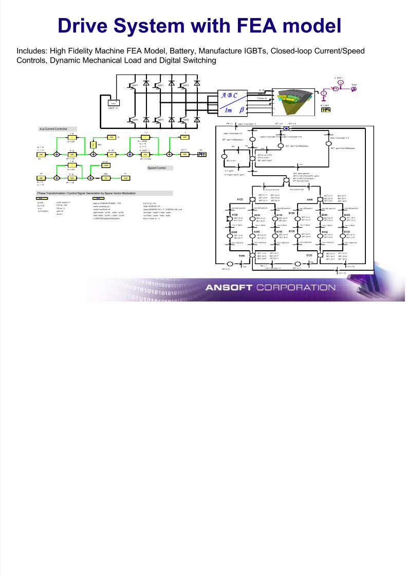
Drive System with FEA model
7/16/2019 Motor Design Suite V12
http://slidepdf.com/reader/full/motor-design-suite-v12-5633856f5983f 54/60
Includes: High Fidelity Machine FEA Model, Battery, Manufacture IGBTs, Closed-loop Current/Speed
Controls, Dynamic Mechanical Load and Digital Switching
GAIN
n
GAIN
u st i n
GAIN iq
Y t
ust
d-q-Current Controller
Speed Control
Yt
M L OAD
Phase Transformation / Control Signal Generation by Space Vector Modulation
G(s)
GS2
I
I id
GAIN
id
LIMIT
yq
UL := 10
LL := -10
LIMIT
yd
UL := 10
LL := -10
GAIN
P id
KP := 1.96
G ( s )
GS1
I
I n
KI := 29.02k
UL := 10
LL := -10
GAIN
P PART n
LIMIT
m r ef
KP := 0.1161k
IGBT1 IGBT2 IGBT3
IGBT4 IGBT5 IGBT6
CONST
i d ref
KI := 240
GAIN
P Iq
KP := 1.96
I
I iq
KI := 240
ICA: EQU
PI3:=pi / 3.
P18:=pi / 180.Tp:=1./fp
wu32:=sqrt(3.) / 2.
kA:=0.1
wu3:=sqrt(3.) gam1:=0.
fp:=10k
tx:=0 costhe:=cos(theta_el)
yalph:=costhe * yd.VAL - sinthe * yq.VAL
i1q:=i1beta * costhe - i1alph * sinthe
i1d:=i1alph * costhe + i1beta * sinthe
ybeta:=sinthe * yd.VAL + costhe * yq.VAL
sinthe:=sin(theta_el)
theta_el:=SYMPOD1.PHIDEG * P18
i1beta:=(SYMPOD1.I1A + 2 * SYMPOD1.I1B) / wu3
theta_m:=theta_el / 3.
i1alph:=SYMPOD1.I1A
SET: k:=k+1 SET: gam1:=gam1
SET: kr:=(k-1)*PI3
SET: kl:=k*PI3
kl <= gam1
true
t-tx >= Tp
kr <= gam1 and kl > gam1
yalph > 0 and ybeta >= 0
SET: tx :=t SET : k: =1yalph = 0 and ybeta = 0PRI := 1
(ybeta > 0 and yalph <= 0) or (yalph < 0 and ybeta <= 0)ybeta < 0 and yalph >= 0
SET: gam1:=pi-ASIN(ybeta/y)
SET: gam1:=2*pi+ASIN(ybeta/y)true
true
A126
SET: z3:=0SET: z6:=1
B345
SET: z6:=0SET: z3:=1
A234
SET: z1:=0SET: z4:=1
B246
SET: z5:=0SET: z2:=1
A135
SET: z2:=0SET: z5:=1
B156
SET: z4:=0
SET: z1:=1
A123SET: z3:=1
SET: z4:=0SET: z1:=1
SET: z6:=0
SET: z5:=0SET: z2:=1
E456 SET: z2:=0
SET: z6:=1
SET: z1:=0
SET: z3:=0
SET: z5:=1
SET: z4:=1
t-tx >= t02+tr+tl
t-tx>=t02 and k=2
t-tx >= t02+tr+tl
t-tx>=t02 and k=4
t-tx >= t02+tr+tl
t-tx>=t02 and k=6 t-tx>=t02 and k=5
t-tx >= t02+tr+tlt-tx >= t02+tr+tl
t-tx>=t02 and k=3
t-tx >= t02+tr+tl
t-tx>=t02 and k=1
B234
SET: z3:=1
SET: z6:=0
A246
SET: z4:=1
SET: z1:=0
B135SET: z4:=0
SET: z1:=1
A345
SET: z5:=1
SET: z2:=0
A156SET: z3:=0
SET: z6:=1
B126SET: z2:=1
SET: z5:=0
t-tx >= t02+tr t-tx >= t02+tr t-tx >= t02+tr t-tx >= t02+tr t-tx >= t02+tr t-tx >= t02+tr
E123
SET: z6:=0
SET: z4:=0
SET: z3:=1
SET: z5:=0
SET: z1:=1
SET: z2:=1
A456
SET: z4:=1
SET: z5:=1
SET: z6:=1
SET: z1:=0
SET: z3:=0
SET: z2:=0
SET: tl:=kA*y*Tp*sin(gamr)
SET: gamr:=gam1-kr
SET: tr:= kA*y*Tp*sin(PI3 - gamr)
SET: t02:=(Tp-tr-tl)/2
k=2 or k=4 or k=6 k=1 or k=3 or k=5
SET: k:=0
true PRI := 1
t-tx >= Tp and k = 0 SET: tx:=t
SET: gam1:=ASIN(ybeta/y)
true
true
t-tx >= Tp
y:=SQRT(SQU(yalph)+SQU(ybeta))
if (y>10.) {y:=10.}
ω+
T
ECE - LINKECE - LINK
TA B C
Im β
Rotor
V R OT1
TTheta IN
Im_IN
beta IN
Battery
- +
LBATT A1
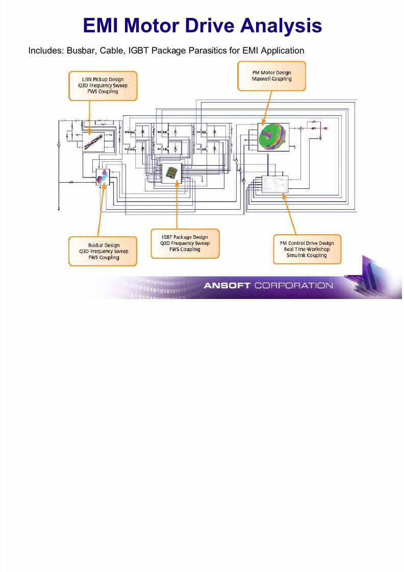
EMI Motor Drive Analysis
7/16/2019 Motor Design Suite V12
http://slidepdf.com/reader/full/motor-design-suite-v12-5633856f5983f 55/60
Includes: Busbar, Cable, IGBT Package Parasitics for EMI Application

7/16/2019 Motor Design Suite V12
http://slidepdf.com/reader/full/motor-design-suite-v12-5633856f5983f 56/60
ePhysics
What is ePhysics ?

7/16/2019 Motor Design Suite V12
http://slidepdf.com/reader/full/motor-design-suite-v12-5633856f5983f 57/60
• Coupled Thermal and Stress Analysis for electromagnetic devices
• Fully integrated with other Ansoft Desktops (Models, Materials, Meshetc.)
• Three Solvers:
9 Static Thermal
9 Transient Thermal9 Static Stress
Magnetic Analysis Thermal Analysis
Thermal Solution for Motors
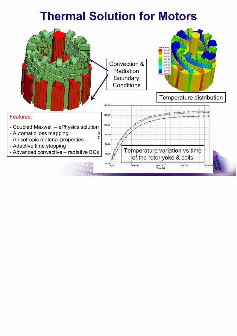
7/16/2019 Motor Design Suite V12
http://slidepdf.com/reader/full/motor-design-suite-v12-5633856f5983f 58/60
Temperature variation vs time
of the rotor yoke & coils
Features:
- Coupled Maxwell – ePhysics solution- Automatic loss mapping
- Anisotropic material properties
- Adaptive time stepping
- Advanced convective – radiative BCs
Convection &Radiation
Boundary
Conditions
Temperature distribution
Stress Solution for Motors
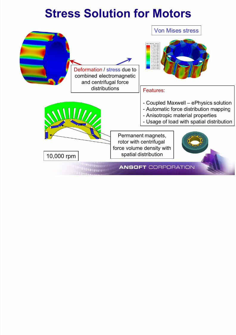
7/16/2019 Motor Design Suite V12
http://slidepdf.com/reader/full/motor-design-suite-v12-5633856f5983f 59/60
Deformation / stress due to
combined electromagnetic
and centrifugal force
distributions
Von Mises stress
Features:
- Coupled Maxwell – ePhysics solution
- Automatic force distribution mapping
- Anisotropic material properties
- Usage of load with spatial distribution
Permanent magnets,
rotor with centrifugal
force volume density with
spatial distribution
10,000 rpm
Embedded PM Motor
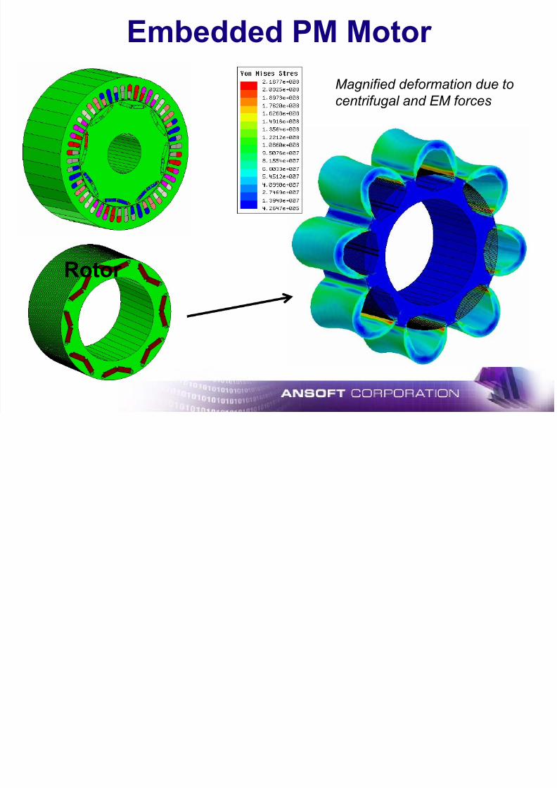
7/16/2019 Motor Design Suite V12
http://slidepdf.com/reader/full/motor-design-suite-v12-5633856f5983f 60/60
Rotor
Magnified deformation due tocentrifugal and EM forces
Top Related