


Languages
Pages
Legal

INSTITUTO SUPERIOR TÉCNICO Universidade Técnica de Lisboa
Morphing Aircraft Structures Design and Testing an Experimental UAV
Pedro Manuel Magalhães da Costa Aleixo
Dissertação para obtenção do Grau de Mestre em
Engenharia Aeroespacial
Júri
Presidente: Prof. Afzal Suleman
Orientador: Prof. Fernando Lau
Co-orientador: Prof. Afzal Suleman
Vogal: Prof. Alexandra Gomes
Outubro de 2007
I
Abstract
This thesis presents the design, build and test of a morphing structure, with the objective
of reducing the wing’s drag. The results of a computational assessment of the morphing
concept benefits are shown. Drag reductions from 5% to nearly 40% at different flight
speeds serve as motivation for designing, building and testing a prototype of the wing,
[24].
Design requirements of the morphing mechanism structure are pointed out and
manufacturing solutions are discussed. The main objective of this work is to prove the
feasibility and functionality of the morphing mechanism solutions. The whole
fabrication process of the wing is described. The difficulties found during the
manufacturing process are presented. Consequently the solutions to mitigate those
difficulties are discussed and the one thought to be the best is pointed.
The final wing is shown and described. The adaptations made in consequence of the
difficulties found during the manufacturing are explained. As a result, not all the
requirements are fulfilled, but the requirements dropped were thought not to have a
crucial influence in the aerodynamic performance.
The use of a flexible skin for the morphing wing is described. Skin stretch and rigidity
influence on the wing’s aerodynamics is studied qualitatively. Three different types of
skins, were tested and compared; the best solution was used to perform the tests to
prove the concept.
Wind tunnel test results are shown and are submitted to analysis. Different wing
planform tests performed with the morphing wing are described and drag reduction is
quantified for different airspeeds. The results achieved a drag reduction up to 25% when
compared to a fixed wing.
Finally it was found that the wing achieved its purpose and opened a new window to
keep the development of these types of wings. Possible further work suggestions are
made, such as wing structure and skin developments.
Key-words: morphing wing, structure, drag reduction, prototype, wind tunnel.
II
Resumo
O trabalho apresentado nesta tese versa sobre o design, construção e teste de uma
estrutura capaz de alterar a sua forma, com o objectivo de minimizar a resistência ao
avanço. Os resultados dos estudos computacionais são apresentados, assim comoas suas
vantagens. A redução da resistência de 5% até quase 40%, em diferentes velocidades de
voos, servem de motivação para o design, construção e teste de um protótipo da asa,
[24].
Os requisitos de design do mecanismo da estrutura são nomeados e as soluções para a
construção são discutidos. O principal objectivo deste trabalho é provar a viabilidade e
funcionalidade do mecanismo adaptativo proposto. Todo o processo de fabrico da asa é
descrito. As dificuldades encontradas durante o processo são apresentadas,
consequentemente as soluções para resolver estes problemas são discutidas e a solução
que apresentou melhores condições é implementada.
O modelo final da asa é apresentado e descrito. As adaptações feitas ao modelo, em
consequência das dificuldades de construção, são explicadas. Como tal, nem todos os
requisitos são cumpridos. No entanto, o requisitos deixados para trás são os que menos
influenciam o desmpenho aerodinâmico.
A utilização de um casca flexível é descrita. A influência do nível de extensão e da
rigidez da casca na aerodinâmica é qualitativamente estudada. Para tal são usadas três
diferentes cascas. Estas cascas foram testadas e a melhor solução foi usada para realizar
os testes para provar este conceito.
Os resultados do túnel de vento são mostrados e sujeitos a análise. As diferentes formas
da asa adaptativa foram testados para vérias velocidades, sendo a redução da resistência
em relação à asa fixa, calculada para cada caso; valores máximos de 25% de redução
foram observados.
Finalmente foi concluido que a asa proposta atingiu os seus objectivos e abriu novas
janelas para continuar o desenvolvimento desta solução. São feitas sugestões para
melhorar a asa proposta, como alterações à estrutura e casca.
Palavras-chave: morphing wing, estrutura, redução de resistência, protótipo, tunel
aerodinâmico.
III
Acknowledgments
This thesis means the end of my graduation, therefore I must be grateful to a lot of
persons who helped me and supported me throughout my long journey at Instituto
Superior Técnico.
Professor Afzal Suleman gave me the opportunity to work in such a revolutionary and
ambitious project I address my acknowledgments.
To José Vale, with whom I had the pleasure to work with, my gratitude for the help and
the guidelines that he gave me during the project. Without his help I could never
developed my work.
I am thankful to Professor Fernando Lau for his endless efforts to make this thesis better
and for the work he is developing to make the course of Aerospace Engineering better,
demander and with higher quality.
A special thanks to my colleague mates who made my studies much more interesting
for the discussions, different points of views in several subjects and the helpful notes to
study. I consider this one of most important part for my work.
I am deeply grateful to Filipa, for her enormous patience to help me in every single
issue I needed and her endless support and encouragement during all these times. She
has been my pillar.
Finally and the most important, to my family: my mother, Maria, and my sisters,
Andrea and Ana, to whom I hardly can express my gratitude and of whom I am very
proud. They listened, advised and supported me in all my decisions, which became to
me the fountain of strength and courage.
To Maria, Andrea, Ana and Filipa, who have been my foundation and I hope that I
made them proud, I dedicate this thesis.
IV
Contents
ABSTRACT..................................................................................................................................I
RESUMO .................................................................................................................................... II
ACKNOWLEDGMENTS ........................................................................................................III
LIST OF FIGURES ..................................................................................................................VI
LIST OF TABLES .................................................................................................................VIII
LIST OF TABLES .................................................................................................................VIII
CHAPTER 1 ................................................................................................................................ 1
1 - INTRODUCTION ................................................................................................................. 1
1.1 - BACKGROUND AND MOTIVATION ........................................................................... 1
1.2 - STATE OF THE ART........................................................................................................ 4
1.3 - SCOPE ............................................................................................................................... 10
1.4 - LAYOUT ........................................................................................................................... 11
CHAPTER 2 .............................................................................................................................. 12
2 - SPECIFIC BACKGROUND............................................................................................... 12
2.1 - AERODYNAMIC SHAPE OPTIMIZATION ............................................................... 12
2.1.1 - AERODYNAMIC SHAPE OPTIMIZATION RESULTS .............................................. 14
2.2 - STRUCTURAL DESIGN................................................................................................. 14
2.2.1 - WING FEM STRUCTURAL MODEL ........................................................................... 15
2.3 - COUPLED AERO-STRUCTURAL ANALYSIS .......................................................... 16
2.3.1 - COUPLED AERO-STRUCTURAL ANALYSIS RESULTS......................................... 17
2.4 - WING DRAG RESULTS................................................................................................. 19
2.4.1 - MORPHING WING CONCEPT LIMITATIONS .......................................................... 20
CHAPTER 3 .............................................................................................................................. 21
3 - STRUCTURAL DESIGN | WING ..................................................................................... 21
3.1 - MORPHING MECHANISM DESIGN FOR WIND TUNNEL TESTING................. 22
3.1.1 - MECHANISM DESIGN ................................................................................................. 23
V
3.1.2 - MECHANISM SIZING................................................................................................... 26
3.1.3 - SIZING OF RIB THREADED SHAFTS ........................................................................ 27
3.1.3.1 - SIZING OF THE SPARS ............................................................................................. 28
3.1.3.2 - SPARS ACTUATION MECHANISM THREADED SHAFTS .................................. 29
3.1.3.3 - TIP, ROOT AND ACTUATION PLATES .................................................................. 30
3.1.3.4 - ROTATING RIB NUT ................................................................................................. 30
3.1.3.5 - ACTUATION MECHANISM NUTS .......................................................................... 31
3.1.3.6 - CENTRAL BLOCK, LEADING AND TRAILING EDGE BLOCKS AND BEAMS 31
3.1.3.7 - CONNECTING PINS................................................................................................... 32
3.1.3.7 - ACTUATION TORQUE REQUIREMENTS .............................................................. 32
3.2 - WING MANUFACTURING ........................................................................................... 33
3.2.1 - NEW SKIN MATERIAL DESCRIPTION...................................................................... 38
CHAPTER 4 .............................................................................................................................. 40
4 - WIND TUNNEL TEST ....................................................................................................... 40
4.1 - TESTS................................................................................................................................ 40
4.1.1 - TESTED CONFIGURATIONS OF THE MORPHING WING...................................... 42
CHAPTER 5 .............................................................................................................................. 44
5 - RESULTS ANALYSIS ........................................................................................................ 44
5.1 - DETAIL ANALYSIS........................................................................................................ 44
5.1.1 - MORPHING WING CONFIGURATIONS COMPARISON ......................................... 47
CHAPTER 6 .............................................................................................................................. 51
6 - SYNTHESIS......................................................................................................................... 51
6.1 - CONCLUSIONS ............................................................................................................... 51
6.2 - FURTHER WORK........................................................................................................... 52
REFERENCES.......................................................................................................................... 54
VI
List of figures
FIGURE 1 - HIGH-LIFT DEVICES...........................................................................................................2
FIGURE 2 - F-14 TOM CAT: UNSWEPT AND SWEPT WINGS ...........................................................2
FIGURE 3 - FLEXIBLE WING ON A MICRO AIRCRAFT ....................................................................4
FIGURE 4 - SEGMENTED WING ............................................................................................................5
FIGURE 5 - HECS WING, ON THE LEFT: VIRGINIA UNIVERSITY; ON THE RIGHT: CORNELL
UNIVERSITY ....................................................................................................................................5
FIGURE 6 - INFLATABLE WINGS, ON THE LEFT: UNIVERSITY OF KENTUCKY; ON THE
RIGHT: DOVER ................................................................................................................................6
FIGURE 7 - CONFORMAL FLAPS ..........................................................................................................6
FIGURE 8 - VARIABLE CANT ANGLES................................................................................................6
FIGURE 9 - STANDARD, LOITER, DASH AND MANOEUVRE..........................................................7
FIGURE 10 - MORPHING AIRCRAFTS, ON THE LEFT: N-MAS; ON THE RIGHT: APVE ..............8
FIGURE 11 - LOCKHEED MARTIN’S MORPHING AIRCRAFT..........................................................8
FIGURE 12 - VARIABLE SPAN MORPHING WING.............................................................................9
FIGURE 13 - AIRFOIL SECTIONS AND WING PLANFORMS FOR FIVE SPEEDS ........................13
FIGURE 14 - WING MODEL SHOWING (ABOVE) THE UNDEFORMED AND STRETCHED SKIN
..........................................................................................................................................................16
FIGURE 15 - FLOW CHART OF COUPLED AERO-STRUCTURAL ANALYSIS OF AN OPTIMUM
MORPHING WING AT DIFFERENT FLIGHT SPEEDS ..............................................................17
FIGURE 16 - AIRFOIL SECTIONS AT WING TIP AND WING PLANFORMS FOR FIVE SPEEDS
FROM THE AERO-STRUCTURAL ANALYSIS...........................................................................18
FIGURE 17 - COMPARISON OF DRAG AND ANGLE OF ATTACK ESTIMATES OF THE
ORIGINAL WING, THE OPTIMIZED MORPHING WING AND THE DEFORMED
MORPHING WING FOR VARIOUS FLIGHT SPEEDS................................................................19
FIGURE 18 - MORPHING MECHANISM CONCEPTUAL CAPABILITY..........................................21
FIGURE 19 - DESIGNED RIB EXTENSION MECHANISM: ON THE LEFT EXTENDED, ON THE
RIGHT RETRACTED......................................................................................................................23
FIGURE 20 - RIB PARTS: ON THE LEFT ASSEMBLED RIB EXPANSION MECHANISM; ON THE
RIGHT CENTRAL BLOCK ............................................................................................................24
FIGURE 21 - RIB PARTS: ON TOP LEFT LEADING EDGE BLOCK; ON TOP RIGHT TRAILING
EDGE BLOCK ;ON BOTTOM LEFT LEADING EDGE SHAPING BEAMS; ON BOTTOM
RIGHT TRAILING EDGE SHAPING BEAMS..............................................................................24
FIGURE 22 - LEADING AND TRAILING EDGE BEAMS ASSEMBLY WITH THE RIB
EXPANSION MECHANISMS: TOP LEFT: STRAIGHT LEADING EDGE ASSEMBLY; TOP
RIGHT: TAPERED LEADING EDGE ASSEMBLY; BOTTOM LEFT: STRAIGHT TRAILING
EDGE ASSEMBLY; BOTTOM RIGHT TAPERED TRAILING EDGE ASSEMBLY .................25
VII
FIGURE 23 - SPAN EXTENSION MECHANISM: ON THE RIGHT: SPAR EXPANSION
MECHANISM AND ON THE LEFT SPAN ACTUATION MECHANISM .................................25
FIGURE 24 - COMPLETE ASSEMBLY OF THE MORPHING WING STRUCTURE ........................26
FIGURE 25 - ON THE LEFT: RIB THREADED SHAFT FEM MESH; RIB THREADED SHAFT
EQUIVALENT VON MISES STRESS............................................................................................28
FIGURE 26 – ON THE TOP LEFT: SPAR ECCENTRICALLY LOADED FEM MESH; ON THE TOP
RIGHT: SPAR ECCENTRICALLY LOADED EQUIVALENT VON MISES STRESS; ON THE
BOTTOM LEFT: SPAR AND SKIN FEM MESH; ON THE BOTTOM RIGHT: SPAR
EQUIVALENT VON MISES STRESS............................................................................................29
FIGURE 27 - ON THE TOP LEFT: CENTRAL BLOCK FEM MESH; ON THE TOP RIGHT:
CENTRAL BLOCK EQUIVALENT VON MISES STRESS; ON THE MIDDLE LEFT:
LEADING EDGE BLOCK FEM MESH; ON THE MIDDLE RIGHT: LEADING EDGE BLOCK
EQUIVALENT VON MISES STRESS; ON THE BOTTOM LEFT: TRAILING EDGE BLOCK
FEM MESH; ON THE BOTTOM RIGHT: TRAILING EDGE BLOCK EQUIVALENT VON
MISES STRESS ...............................................................................................................................32
FIGURE 28 - SHAFT AND ROTATING NUT .......................................................................................34
FIGURE 29 - LEADING AND TRAILING EDGE SLIDING BEAMS ..................................................35
FIGURE 30 - LEADING AND TRAILING EDGES MADE IN ACRYLIC ...........................................35
FIGURE 31 - CENTRAL BLOCK ...........................................................................................................36
FIGURE 32 - ASSEMBLE RIB................................................................................................................36
FIGURE 33 - ASSEMBLE WING: IN THE LEFT: EXTENDED; ON THE RIGHT: RETRACTED....36
FIGURE 34 - FINAL MECHANISM ASSEMBLY.................................................................................38
FIGURE 35 - LICRA FIBRE IN SILICONE MATRIX COMPOSITE MATERIAL FOR THE WING
SKIN.................................................................................................................................................39
FIGURE 36 - WIND TUNNEL TESTING ASSEMBLY: ON THE LEFT: SUPPORTING
STRUCTURE CONNECTED TO THE SCALE ON THE RIGHT: BOTTOM AND SIDE PLATE
PLACED AT THE WIND TUNNEL SECTION .............................................................................40
FIGURE 37 - AERODYNAMIC FORCES RESULTS FOR THE THREE DIFFERENT SKINS
TESTED FOR CONFIGURATION 4 AT 15, 20 AND 25 M/S AIRSPEED..................................45
FIGURE 38 - AERODYNAMIC FORCES RESULTS FOR THE TESTED SKINS AT 35 AND 40 M/S
AIRSPEED .......................................................................................................................................46
FIGURE 39 - INFLUENCE OF AIRSPEED IN CLΑ AND CD FOR SKIN 3........................................47
FIGURE 40 - DRAG VERSUS LIFT CURVES FOR 15, 20 AND 25 M/S AIRSPEEDS AND WING
PLANFORM CONFIGURATIONS.................................................................................................47
FIGURE 41 - DRAG VERSUS LIFT CURVES FOR 35 AND 40 M/S AIRSPEEDS AND WING
PLANFORM CONFIGURATIONS.................................................................................................48
FIGURE 42 - SOLUTION TO CHANGE ACTIVELY THE THICKNESS ............................................53
FIGURE 43 - SOLUTION TO DECREASE TO ACTUATION FORCE ................................................53
VIII
List of Tables
TABLE 1 - PERCENT DRAG REDUCTIONS WITH OPTIMIZED MORPHING WING AND
DEFORMED MORPHING WING ..................................................................................................19
TABLE 2 - MATERIAL MECHANICAL PROPERTIES........................................................................27
TABLE 3 - RIB THREADED SHAFT, SPARS ACTUATION SHAFTS SIZING RESULTS ...............28
TABLE 4 - TIP, ROOT AND ACTUATION PLATES SIZING RESULTS............................................30
TABLE 5 - ROTATING RIB AND ACTUATION NUTS’ SIZING RESULTS......................................31
TABLE 6 - ROTATING RIB AND ACTUATION NUTS SIZING RESULTS.......................................32
TABLE 7 - ROTATING RIB AND ACTUATION NUTS TORQUE REQUIREMENTS ......................33
TABLE 8 - FINAL MORPHING MECHANISM DIMENSIONS RANGES...........................................38
TABLE 9 - LIFT CORRECTIONS FOR GROUND EFFECT .................................................................41
TABLE 10 - LIFT RELATIONS BETWEEN ORIGINAL AND SCALED WING.................................41
TABLE 11 - TESTED CONFIGURATIONS’ GEOMETRIES AND EXPECTED LIFT........................42
TABLE 12 - TESTED SKINS CHARACTERISTICS..............................................................................44
TABLE 13 - MORPHING WING DRAG FOR DIFFERENT PLANFORM CONFIGURATIONS AT
DIFFERENT AIRSPEEDS FOR A 22.73 N REQUIRED LIFT......................................................48
TABLE 14 - MORPHING WING DRAG FOR DIFFERENT PLANFORM AT DIFFERENT
AIRSPEEDS FOR A 18.00 N REQUIRED LIFT ............................................................................49
TABLE 15 - MORPHING WING DRAG FOR DIFFERENT PLANFORM CONFIGURATIONS AT
DIFFERENT AIRSPEEDS FOR A 13.50 N REQUIRED LIFT......................................................49
1
Chapter 1
1 - Introduction
1.1 - Background and Motivation
Airplanes fly under a wide range of temperature, density and wind conditions. They also
have to perform different flight manoeuvres during a flight: take off, landing, cruise,
climb, coordinated turns and others manoeuvres. To perform efficiently in these
conditions the aircraft is required to have different configurations.
The aircrafts are designed to have the best performance in the most important flight
stage, which depend on the mission that the aircraft have to accomplish. For commercial
aircrafts the most important stage is cruise while for militaries aircrafts usually is
manoeuvring. When they fly out of the optimal flight condition, the performance is
severely affected. The ability to change the aerodynamic shape to increase the optimal
flight envelope is highly desirable. This is a very ambitious goal that motivates aircraft
designers to invent and create new innovative solutions for structural concepts.
Aeronautical history is full of innovative solutions to adapt aircraft. For instance,
Wright brothers used warping wings to provide lateral control for the Wright B flyer by
twisting the wings, but this concept vanished from the designers’ mind because it
requires high energy actuation. At that time there wasn’t enough technology to keep
developing this solution.
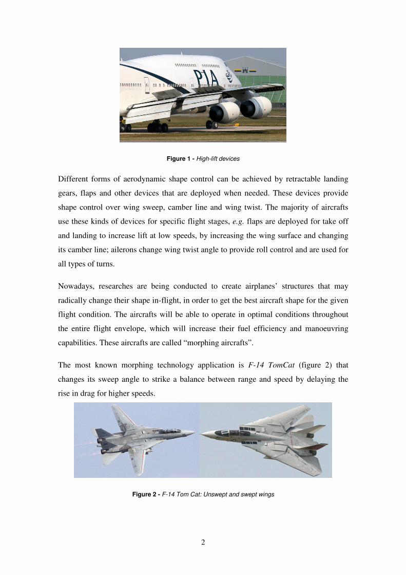
Although fixed wings must operate under the design condition, this is not possible
often, especially in aircrafts which have a wide operating range, like surveillance and
military aircrafts. For commercial aircrafts during take off, landing and other short flight
stages, high-lift devices are used to improve the performance (figure 1).
2
Figure 1 - High-lift devices
Different forms of aerodynamic shape control can be achieved by retractable landing
gears, flaps and other devices that are deployed when needed. These devices provide
shape control over wing sweep, camber line and wing twist. The majority of aircrafts
use these kinds of devices for specific flight stages, e.g. flaps are deployed for take off
and landing to increase lift at low speeds, by increasing the wing surface and changing
its camber line; ailerons change wing twist angle to provide roll control and are used for
all types of turns.
Nowadays, researches are being conducted to create airplanes’ structures that may
radically change their shape in-flight, in order to get the best aircraft shape for the given
flight condition. The aircrafts will be able to operate in optimal conditions throughout
the entire flight envelope, which will increase their fuel efficiency and manoeuvring
capabilities. These aircrafts are called “morphing aircrafts”.
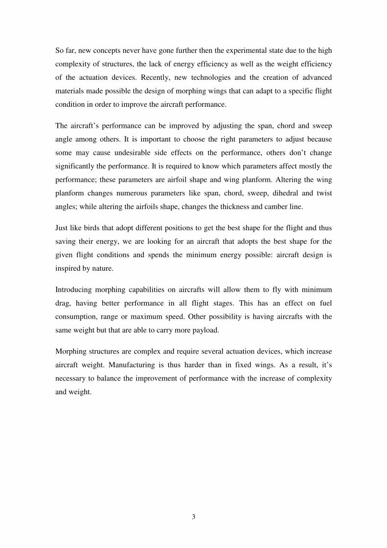
The most known morphing technology application is F-14 TomCat (figure 2) that
changes its sweep angle to strike a balance between range and speed by delaying the
rise in drag for higher speeds.
Figure 2 - F-14 Tom Cat: Unswept and swept wings
3
So far, new concepts never have gone further then the experimental state due to the high
complexity of structures, the lack of energy efficiency as well as the weight efficiency
of the actuation devices. Recently, new technologies and the creation of advanced
materials made possible the design of morphing wings that can adapt to a specific flight
condition in order to improve the aircraft performance.
The aircraft’s performance can be improved by adjusting the span, chord and sweep
angle among others. It is important to choose the right parameters to adjust because
some may cause undesirable side effects on the performance, others don’t change
significantly the performance. It is required to know which parameters affect mostly the
performance; these parameters are airfoil shape and wing planform. Altering the wing
planform changes numerous parameters like span, chord, sweep, dihedral and twist
angles; while altering the airfoils shape, changes the thickness and camber line.
Just like birds that adopt different positions to get the best shape for the flight and thus
saving their energy, we are looking for an aircraft that adopts the best shape for the
given flight conditions and spends the minimum energy possible: aircraft design is
inspired by nature.
Introducing morphing capabilities on aircrafts will allow them to fly with minimum
drag, having better performance in all flight stages. This has an effect on fuel
consumption, range or maximum speed. Other possibility is having aircrafts with the
same weight but that are able to carry more payload.
Morphing structures are complex and require several actuation devices, which increase
aircraft weight. Manufacturing is thus harder than in fixed wings. As a result, it’s
necessary to balance the improvement of performance with the increase of complexity
and weight.
4
1.2 - State of the Art
Morphing aircrafts can bring many advantages to aeronautical industries and to
militaries. Therefore, a lot of research in this area has been done due to the prospect of
large benefits.
The latest research has been made on Unmanned Aerials Vehicles (UAV) with
morphing technology and drones, because it is easy to build for experiments due to its
size, therefore accessible to universities and students.
The advance in new materials improves the design and new materials are developed
everyday. As a result they allow the development of new structures and actuation
mechanisms, since they are lighter, reliable and stiffer.
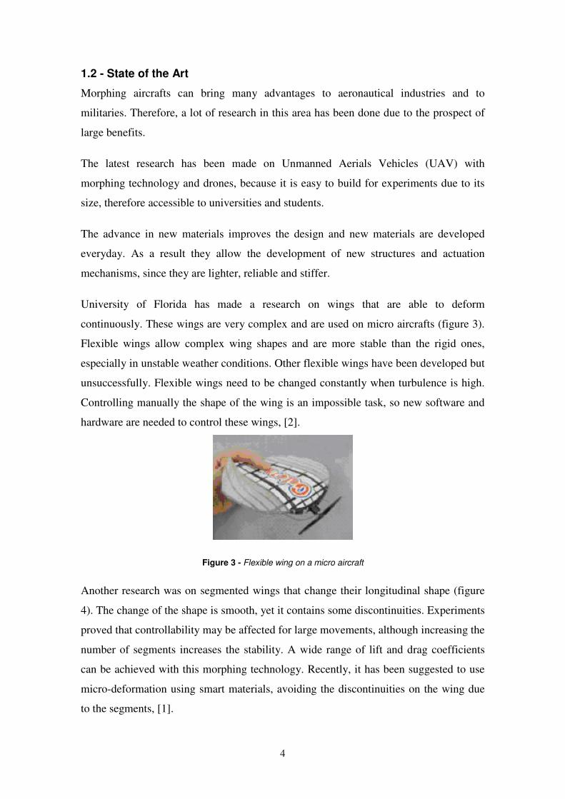
University of Florida has made a research on wings that are able to deform
continuously. These wings are very complex and are used on micro aircrafts (figure 3).
Flexible wings allow complex wing shapes and are more stable than the rigid ones,
especially in unstable weather conditions. Other flexible wings have been developed but
unsuccessfully. Flexible wings need to be changed constantly when turbulence is high.
Controlling manually the shape of the wing is an impossible task, so new software and
hardware are needed to control these wings, [2].
Figure 3 - Flexible wing on a micro aircraft
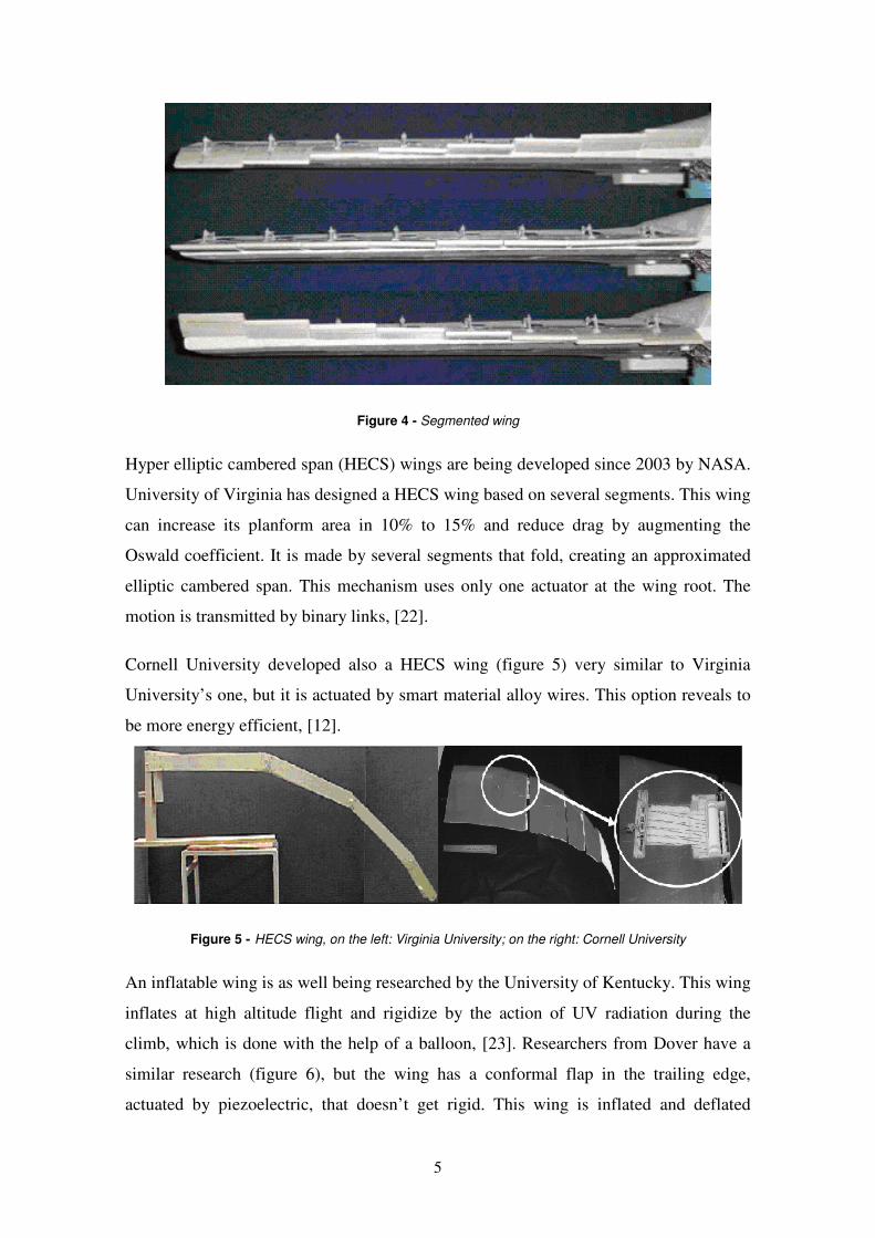
Another research was on segmented wings that change their longitudinal shape (figure
4). The change of the shape is smooth, yet it contains some discontinuities. Experiments
proved that controllability may be affected for large movements, although increasing the
number of segments increases the stability. A wide range of lift and drag coefficients
can be achieved with this morphing technology. Recently, it has been suggested to use
micro-deformation using smart materials, avoiding the discontinuities on the wing due
to the segments, [1].
5
Figure 4 - Segmented wing
Hyper elliptic cambered span (HECS) wings are being developed since 2003 by NASA.
University of Virginia has designed a HECS wing based on several segments. This wing
can increase its planform area in 10% to 15% and reduce drag by augmenting the
Oswald coefficient. It is made by several segments that fold, creating an approximated
elliptic cambered span. This mechanism uses only one actuator at the wing root. The
motion is transmitted by binary links, [22].
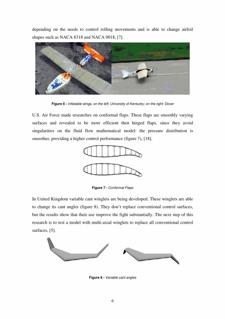
Cornell University developed also a HECS wing (figure 5) very similar to Virginia
University’s one, but it is actuated by smart material alloy wires. This option reveals to
be more energy efficient, [12].
Figure 5 - HECS wing, on the left: Virginia University; on the right: Cornell University
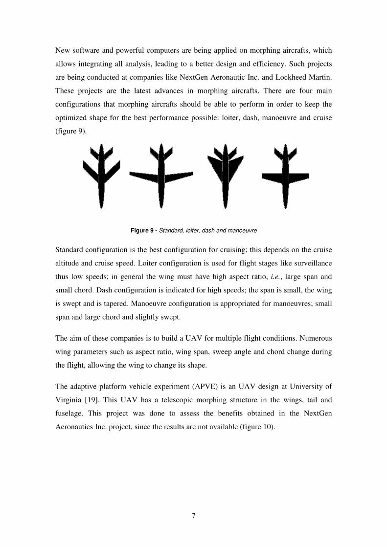
An inflatable wing is as well being researched by the University of Kentucky. This wing
inflates at high altitude flight and rigidize by the action of UV radiation during the
climb, which is done with the help of a balloon, [23]. Researchers from Dover have a
similar research (figure 6), but the wing has a conformal flap in the trailing edge,
actuated by piezoelectric, that doesn’t get rigid. This wing is inflated and deflated
6
depending on the needs to control rolling movements and is able to change airfoil
shapes such as NACA 8318 and NACA 0018, [7].
Figure 6 - Inflatable wings, on the left: University of Kentucky; on the right: Dover
U.S. Air Force made researches on conformal flaps. These flaps are smoothly varying
surfaces and revealed to be more efficient then hinged flaps, since they avoid
singularities on the fluid flow mathematical model: the pressure distribution is
smoother, providing a higher control performance (figure 7), [18].
Figure 7 - Conformal Flaps
In United Kingdom variable cant winglets are being developed. These winglets are able
to change its cant angles (figure 8). They don’t replace conventional control surfaces,
but the results show that their use improve the fight substantially. The next step of this
research is to test a model with multi-axial winglets to replace all conventional control
surfaces, [5].
Figure 8 - Variable cant angles
7
New software and powerful computers are being applied on morphing aircrafts, which
allows integrating all analysis, leading to a better design and efficiency. Such projects
are being conducted at companies like NextGen Aeronautic Inc. and Lockheed Martin.
These projects are the latest advances in morphing aircrafts. There are four main
configurations that morphing aircrafts should be able to perform in order to keep the
optimized shape for the best performance possible: loiter, dash, manoeuvre and cruise
(figure 9).
Figure 9 - Standard, loiter, dash and manoeuvre
Standard configuration is the best configuration for cruising; this depends on the cruise
altitude and cruise speed. Loiter configuration is used for flight stages like surveillance
thus low speeds; in general the wing must have high aspect ratio, i.e., large span and
small chord. Dash configuration is indicated for high speeds; the span is small, the wing
is swept and is tapered. Manoeuvre configuration is appropriated for manoeuvres; small
span and large chord and slightly swept.
The aim of these companies is to build a UAV for multiple flight conditions. Numerous
wing parameters such as aspect ratio, wing span, sweep angle and chord change during
the flight, allowing the wing to change its shape.
The adaptive platform vehicle experiment (APVE) is an UAV design at University of
Virginia [19]. This UAV has a telescopic morphing structure in the wings, tail and
fuselage. This project was done to assess the benefits obtained in the NextGen
Aeronautics Inc. project, since the results are not available (figure 10).
8
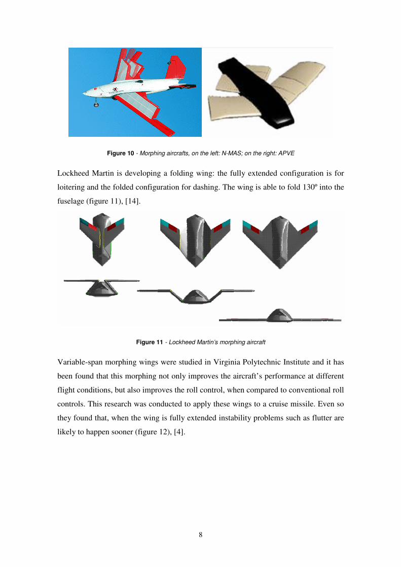
Figure 10 - Morphing aircrafts, on the left: N-MAS; on the right: APVE
Lockheed Martin is developing a folding wing: the fully extended configuration is for
loitering and the folded configuration for dashing. The wing is able to fold 130º into the
fuselage (figure 11), [14].
Figure 11 - Lockheed Martin’s morphing aircraft
Variable-span morphing wings were studied in Virginia Polytechnic Institute and it has
been found that this morphing not only improves the aircraft’s performance at different
flight conditions, but also improves the roll control, when compared to conventional roll
controls. This research was conducted to apply these wings to a cruise missile. Even so
they found that, when the wing is fully extended instability problems such as flutter are
likely to happen sooner (figure 12), [4].

9
Figure 12 - Variable Span Morphing Wing
Materials are very important in aeronautic industry due to the dichotomy of weight and
strain, hardness and flexibility and much work has been done to develop a material that
can be lighter but stiffer, hard but flexible. In the last years, researches have been
focused on composite materials, since it allows both rigid and flexible materials.
Projects such as NextGen use flexible composite materials.
Memory shape materials are being researched also. These materials are very promising
due to the possibility of changing its shape by the use of an electric sign or by varying
the temperature. Bending materials technology is preferable to the segmented wing,
since it provides a smooth airfoil, avoiding steps that cause turbulence in the flow.
However, smart materials have a long way to go to became reliable, [9].
University of Bristol is researching composite plates that are bi-stable and allow
swapping positions. These materials use the orthotropic proprieties to change its
position, [11].
Other materials based on nanotechnology and on spider silk are being researched.
Nanotechnology [15] is very promising due to its materials properties, since it has a
great tensile strength. But there is long way to go on the development of this
technology. Spider silk is hard to synthesise and DNA manipulation is on the very first
steps, [21].
The University of Virginia found a plastic material that could become the best material
for morphing wings (Tecoflex ©), because it requires less force to deform than other
tested materials. The other materials that they have tested are shape memory polymers,
polyurethanes among others [10].
10
1.3 - Scope
The present thesis is a part of a wider project that involves aerodynamic and structural
optimization. This part of the wider project is to design, build and test a prototype of a
morphing wing.
In this thesis I present the design and construction of a morphing wing that changes its
chord and span, unlike the ones I have stated before that only changes one parameter:
chord, span, dihedral angle or sweep angle. The project of APVE, NextGen and
Lockheed also change more than one parameter. Although NextGen and Lockheed
projects are not known deeply, due to the fact that they are being developed by
companies.
The first part of this thesis was the design of structure that was able to change the chord
and the span. Initially the aim was to change the airfoil thickness but this requirement
was dropped due to the high complexity that it involves.
The chord has to increase its minimum size of 0.22m to 0.33m, the span of 2.4m to
3.4m, the thickness also varies between 14mm and 25.2mm but that was not possible to
accomplish with the means we had.
The design was made using SolidWorks© software after dimensioning the structure
based on the loads calculated before. The dimensioning was done by the use of
ANSYS© software for numerical calculus; analytically formulas were used for the
simple calculus.
Afterwards, we built the prototype. This task took place at IST mechanical facilities. We
used the milling machine, the folding machine and the driller, in order to build every
parts of the wing’s structure: ribs, spars and central blocks.
With the prototype built we made some wind tunnel tests at AFA (Academia da Força
Aérea) aeronautical laboratory facility, using their wind tunnel. The wind tunnel tests
had the objective of evaluating the wing’s performance. Those results were compared
with the computational results.
This thesis validates the previous work done and led to a paper published at RTO
(Research and Technology Organisation) of NATO last April, [8].
11
1.4 - Layout
In the second chapter it is summarized the previous studies of aerodynamic shape
optimization, structural design and coupled aero-structural analysis. The objective of
this morphing wing is to be able to fly with a constant lift, equal to aircraft weight, with
the lowest drag possible, [24].
In the third chapter it is presented the wing structural design as well as the options taken
and its justifications. In the first part of this chapter we describe the geometric and loads
requirements for the wind tunnel and the adaptations made to the wing. Then a
description of the wing mechanism concept, its design and all the components are
described. Afterwards, the sizing of the mechanism components is done. The
manufacturing itself is explained, including the adaptations made during the
construction. Finally different skins materials are described.
The fourth chapter describes the method used for the wind tunnel tests, the structure
assembled to support the wing in the tunnel. Also we describe the configurations used
as well as the objective for each configuration.
Chapter five presents the results and its analysis. First of all, the different skins results
are analysed. The best skin is chosen and the results of the different configurations
using the chosen skin are presented. The emphasis is on the L vs. D charts, because
these are the parameters that show us if morphing wings have advantages over classic
wings.
Sixth chapter sets the conclusions and further work to improve this specific morphing
wing, by altering the chord and the span.
12
Chapter 2
2 - Specific Background
In this chapter it is summarized the previous studies of aerodynamic shape optimization,
structural design and coupled aero-structural analysis. The objective of this morphing
wing is to be able to fly with a constant lift, equal to aircraft weight, with the lowest
drag possible, [8, 24].
2.1 - Aerodynamic Shape Optimization
The aerodynamic analysis is done in two steps. First, the 2-dimensional (2D)
aerodynamic coefficients as functions of angle of attack and Reynolds number (Re) at
specified wing sections across the span are obtained. The airfoils are represented by b-
spline control points. Then, a non-linear lifting-line method [3] algorithm is used to
obtain the lift distribution and induced drag. The lift and the parasite drag are obtained
by integrating the lift and parasite drag coefficients corresponding to all local angles of
attack. The wing is represented by the chord and incidence at specified sections along
the semi-span. The sections’ aerodynamic information comes from the previous step.
The aerodynamic shape optimization is carried out with the sequential quadratic
programming (SQP).
A total of 13 design variables are adopted in this design problem. The design variables
are the angle of attack, α, the span of the wing, b, and the chord length, c, at two semi-
span positions (the chord where the wing joins the central wing and the tip chord) and
the airfoil shape. In this case, the span is allowed to vary between 2.4m and 3.4m and
the chord length is limited to a minimum of 0.22m and a maximum of 0.33m. The
variation of the chord length between these two design chords is linear. The airfoils at
the reference stations can change its thickness and camber distributions only limited by
a thickness in the range 14mm to 25.2mm. There is no twist of the wing since the
morphing concept does not permit such mechanism and the sweep angle at quarter
chord position is kept constant and equal to zero. These geometric constraints are
13
imposed due to the physical limitations of the morphing mechanisms and the rubber-
like material to be used for the skin. A fixed leading edge diameter, φLE, is imposed
since the morphing mechanism concept does not allow it to be changed.
The aim of the optimization is to minimize the drag of the wing at speeds between
15m/s and 50m/s. The lift required is the UAV weight of 100N.
The last design variables are the abcissas of the airfoil’s b-spline control points
coordinates non-dimensionalized by the chord length.
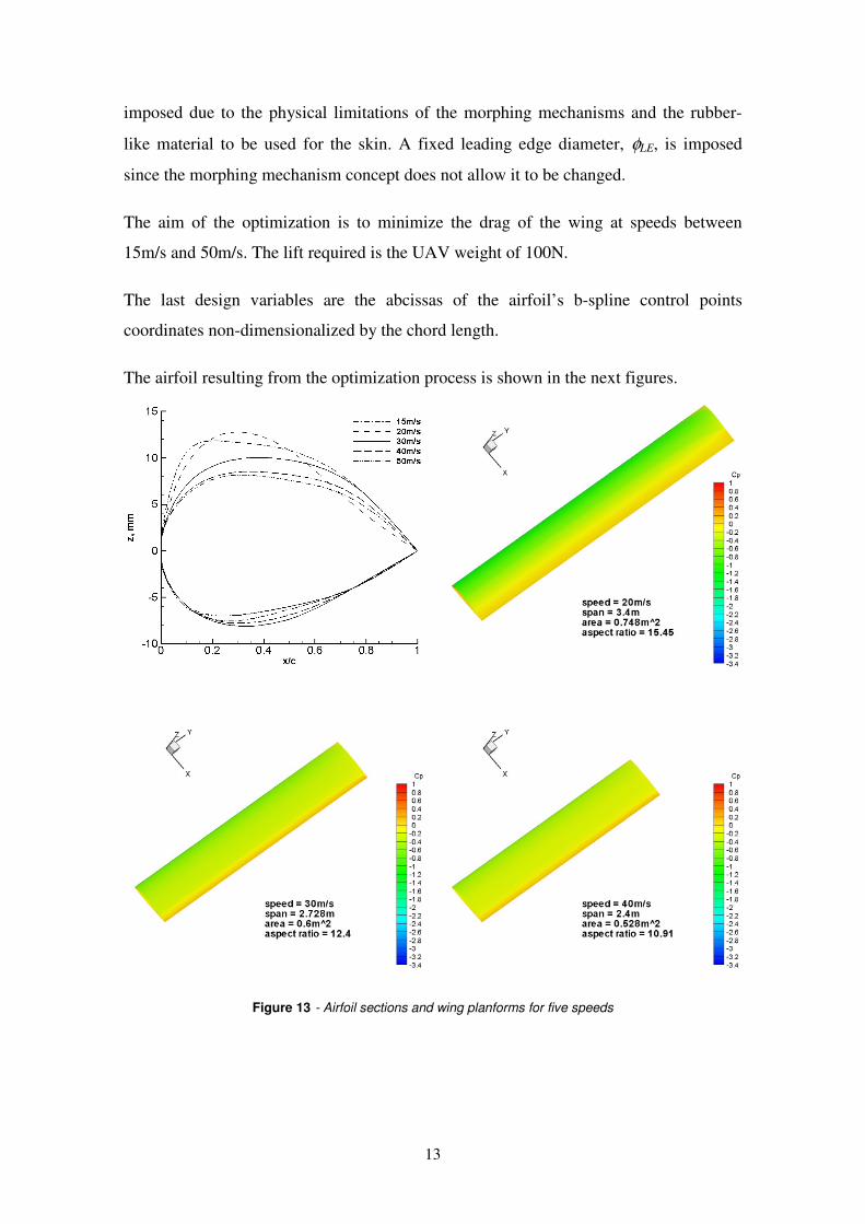
The airfoil resulting from the optimization process is shown in the next figures.
Figure 13 - Airfoil sections and wing planforms for five speeds
14
2.1.1 - Aerodynamic Shape Optimization Results
The optimized geometry of the morphing wing is summarized in figure 13. It can be
observed that, as speed reduces, the airfoil thickens up and the camber increases with its
maximum value moving slightly forward on the chord. The solution at lower speeds
was very much restricted by the airfoil geometry constraints. Since the morphing
concept has limited capability to increase thickness, the maximum allowable wing
planform area was never attained because, for the maximum chord length, the airfoil
becomes so thin (about 6.3% of relative thickness) that its maximum lift coefficient is
very low and the extra area is not sufficient to outperform the higher maximum lift
coefficient obtained from a slightly thicker airfoil with smaller chord length. The drag
results are presented in sub-section 2.4 below together with the drag results of the
conventional wing and the deformed wing obtained from the aero-structural analysis.
2.2 - Structural Design
In order to achieve the desired shape changes for the morphing wing, the skin material
has to endure high strains, which is not the case with the materials usually used in
conventional aircraft. Therefore, rigid materials, as metals or high stiffness/low strain
polymer membranes, were ruled out. Rubber materials and other polymers could be
considered candidates, including new smart materials as shape memory polymers.
Nevertheless, vulcanized rubber was chosen to be the skin material, due to its
availability, low price and the desire to prove the feasibility of the morphing concept
without much concern about cyclic fatigue or environmental hazard. The use of a shape
memory polymer was initially considered, but the increase in complexity of the
morphing system due to the heating requirements and the elastic-perfectly plastic
behaviour of such material makes its shape memory properties at least unusable when
the wing is loaded.
The structural model must not only be capable of increasing the chord at a wing section
but also of discretizing the airfoil and allowing changes in airfoil thickness at some
control points. In this work, it is considered that the mechanism divides the airfoil in 6
different sections along the chord, three of them being evenly spaced from the quarter
chord to the leading edge and the last three sections being evenly spaced from the
quarter chord to the trailing edge. The span expansion mechanism is intended to stretch
15
the wing skin and also maintain the rib expansion mechanisms evenly distributed along
the span of the wing.
2.2.1 - Wing FEM Structural Model
The finite element method (FEM) structural model of the wing was built not only to
perform the coupled aerodynamic-structural analysis but also to assess the wing
deformation forces involved in such a structure. Therefore, the model is required to
allow the application of aerodynamic loads on the wing deformable skin and stringers
and simulate some of the moving parts of the morphing mechanism in such a way that
relevant forces and moments acting on it can be obtained.
Rubber like materials can be modelled in a number of ways when a FEM is applied,
traditionally, using a strain energy function dependant only on deviatory deformations.
A variety of strain energy functions are supported by Ansys®, the commercial structural
analysis program.
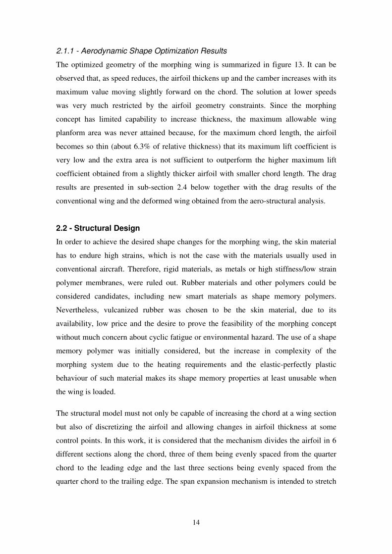
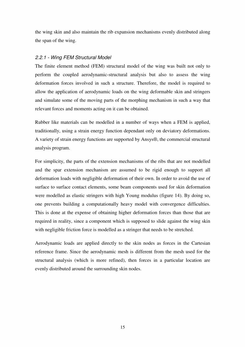
For simplicity, the parts of the extension mechanisms of the ribs that are not modelled
and the spar extension mechanism are assumed to be rigid enough to support all
deformation loads with negligible deformation of their own. In order to avoid the use of
surface to surface contact elements, some beam components used for skin deformation
were modelled as elastic stringers with high Young modulus (figure 14). By doing so,
one prevents building a computationally heavy model with convergence difficulties.
This is done at the expense of obtaining higher deformation forces than those that are
required in reality, since a component which is supposed to slide against the wing skin
with negligible friction force is modelled as a stringer that needs to be stretched.
Aerodynamic loads are applied directly to the skin nodes as forces in the Cartesian
reference frame. Since the aerodynamic mesh is different from the mesh used for the
structural analysis (which is more refined), then forces in a particular location are
evenly distributed around the surrounding skin nodes.
16
Figure 14 - wing model showing (above) the undeformed and stretched skin
A simple convergence study using a section of the wing was performed to assess the
suitability of the FEM mesh. This study revealed that the refinement of the mesh could
solve convergence problems but deformation forces and moments results did not differ
significantly from a less refined mesh to a more refined mesh. Therefore, to reduce
computation time requirements the least refined mesh was chosen to be used in the
structural analysis and more refined meshes were used whenever convergence problems
occurred.
In order to resist and transmit aerodynamic forces to the structure, the wing skin acting
as a membrane must be stretched prior to the loading. However, the rubber material
model used in this work becomes unstable at high stretches, say higher than 170%,
which means that for a fully deformed wing a high initial stretch would cause model
convergence problems. Therefore the initial stretch was adjusted to allow the full
analysis of the wing for each flight condition, bearing in mind that, real rubber materials
can stretch up to 300% and more and that this action will cause error in the prediction of
deformation forces.
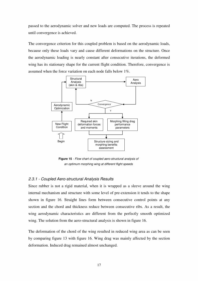
2.3 - Coupled Aero-Structural Analysis
The process used to estimate the morphing wing drag and structural requirements is
illustrated in figure 15. At a given flight condition and aircraft weight, the aerodynamic
optimization tool optimizes the wing shape and passes it together with the aerodynamic
loads to the structural model. Here the structural control points are made coincident to
the aerodynamic control points and the aerodynamic loads are distributed to the skin
FEM nodes. Then, the structural analysis is carried out with the control points fixed and
the deformations of the skin are obtained. In the next iteration, the new wing shape is
17
passed to the aerodynamic solver and new loads are computed. The process is repeated
until convergence is achieved.
The convergence criterion for this coupled problem is based on the aerodynamic loads,
because only these loads vary and cause different deformations on the structure. Once
the aerodynamic loading is nearly constant after consecutive iterations, the deformed
wing has its stationary shape for the current flight condition. Therefore, convergence is
assumed when the force variation on each node falls below 1%.
Structural Analysis
(skin & ribs)
Aero Analysis
New Flight Condition
Required skin deformation forces
and moments
Morphing Wing drag performance parameters
Begin
Aerodynamic Optimization
Convergence
Y
N
Structure sizing and morphing benefits
assessment
Figure 15 - Flow chart of coupled aero-structural analysis of
an optimum morphing wing at different flight speeds
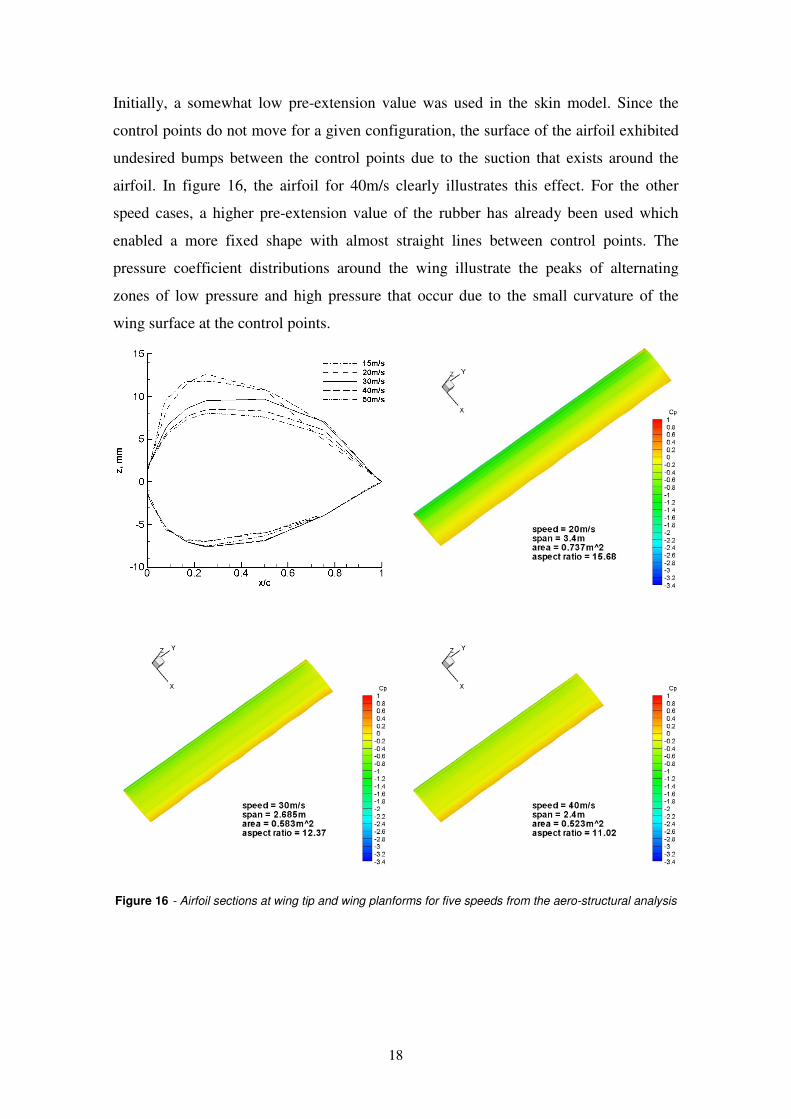
2.3.1 - Coupled Aero-structural Analysis Results
Since rubber is not a rigid material, when it is wrapped as a sleeve around the wing
internal mechanism and structure with some level of pre-extension it tends to the shape
shown in figure 16. Straight lines form between consecutive control points at any
section and the chord and thickness reduce between consecutive ribs. As a result, the
wing aerodynamic characteristics are different from the perfectly smooth optimized
wing. The solution from the aero-structural analysis is shown in figure 16.
The deformation of the chord of the wing resulted in reduced wing area as can be seen
by comparing figure 13 with figure 16. Wing drag was mainly affected by the section
deformation. Induced drag remained almost unchanged.
18
Initially, a somewhat low pre-extension value was used in the skin model. Since the
control points do not move for a given configuration, the surface of the airfoil exhibited
undesired bumps between the control points due to the suction that exists around the
airfoil. In figure 16, the airfoil for 40m/s clearly illustrates this effect. For the other
speed cases, a higher pre-extension value of the rubber has already been used which
enabled a more fixed shape with almost straight lines between control points. The
pressure coefficient distributions around the wing illustrate the peaks of alternating
zones of low pressure and high pressure that occur due to the small curvature of the
wing surface at the control points.
Figure 16 - Airfoil sections at wing tip and wing planforms for five speeds from the aero-structural analysis
19
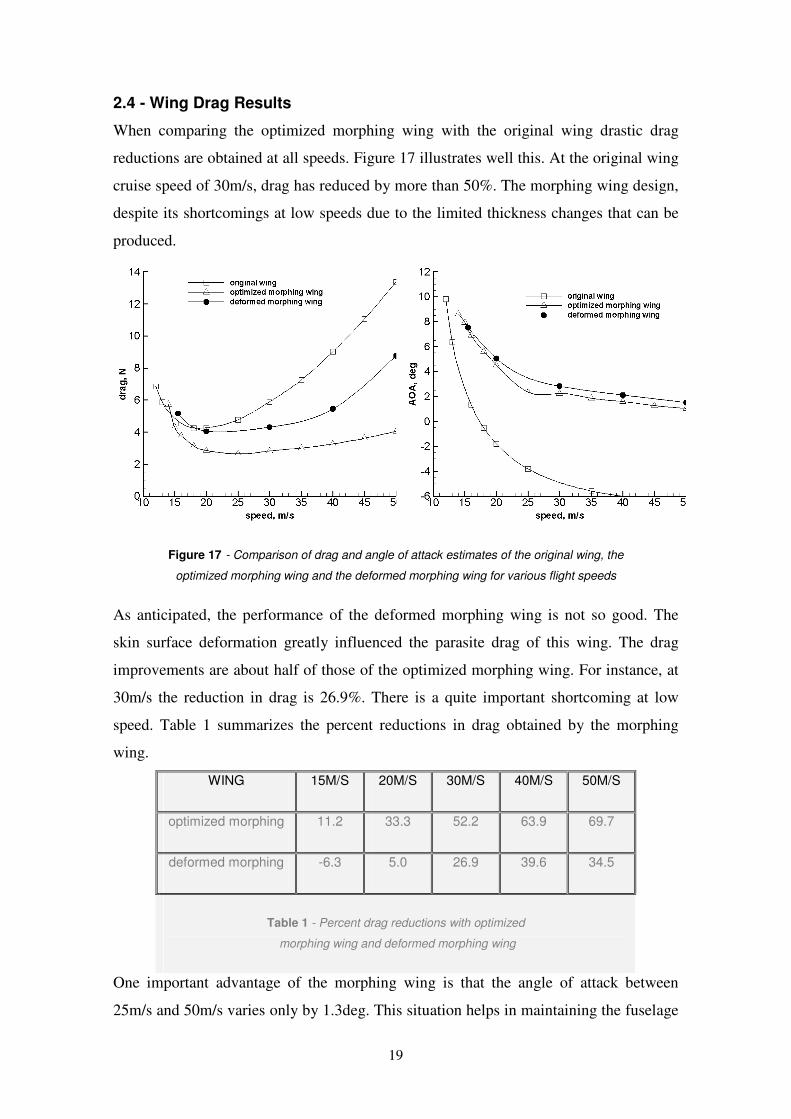
2.4 - Wing Drag Results
When comparing the optimized morphing wing with the original wing drastic drag
reductions are obtained at all speeds. Figure 17 illustrates well this. At the original wing
cruise speed of 30m/s, drag has reduced by more than 50%. The morphing wing design,
despite its shortcomings at low speeds due to the limited thickness changes that can be
produced.
Figure 17 - Comparison of drag and angle of attack estimates of the original wing, the
optimized morphing wing and the deformed morphing wing for various flight speeds
As anticipated, the performance of the deformed morphing wing is not so good. The
skin surface deformation greatly influenced the parasite drag of this wing. The drag
improvements are about half of those of the optimized morphing wing. For instance, at
30m/s the reduction in drag is 26.9%. There is a quite important shortcoming at low
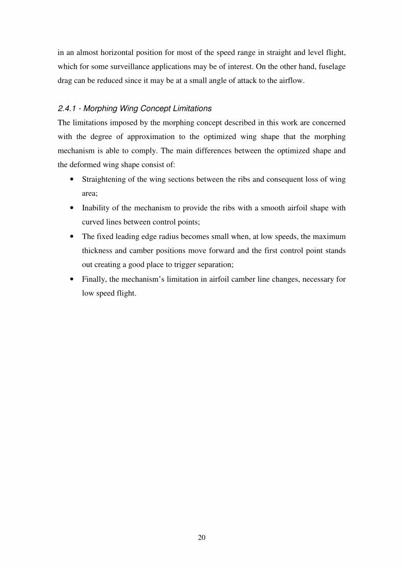
speed. Table 1 summarizes the percent reductions in drag obtained by the morphing
wing.
WING 15M/S 20M/S 30M/S 40M/S 50M/S
optimized morphing 11.2 33.3 52.2 63.9 69.7
deformed morphing -6.3 5.0 26.9 39.6 34.5
Table 1 - Percent drag reductions with optimized
morphing wing and deformed morphing wing
One important advantage of the morphing wing is that the angle of attack between
25m/s and 50m/s varies only by 1.3deg. This situation helps in maintaining the fuselage
20
in an almost horizontal position for most of the speed range in straight and level flight,
which for some surveillance applications may be of interest. On the other hand, fuselage
drag can be reduced since it may be at a small angle of attack to the airflow.
2.4.1 - Morphing Wing Concept Limitations
The limitations imposed by the morphing concept described in this work are concerned
with the degree of approximation to the optimized wing shape that the morphing
mechanism is able to comply. The main differences between the optimized shape and
the deformed wing shape consist of:
• Straightening of the wing sections between the ribs and consequent loss of wing
area;
• Inability of the mechanism to provide the ribs with a smooth airfoil shape with
curved lines between control points;
• The fixed leading edge radius becomes small when, at low speeds, the maximum
thickness and camber positions move forward and the first control point stands
out creating a good place to trigger separation;
• Finally, the mechanism’s limitation in airfoil camber line changes, necessary for
low speed flight.
21
Chapter 3
3 - Structural Design | Wing
This chapter describes the design and construction process of the morphing wing
prototype. The structural forces and moments that the morphing mechanism is required
to withstand were based on the deformation forces and moments obtained from the
structural FEM model, [24].
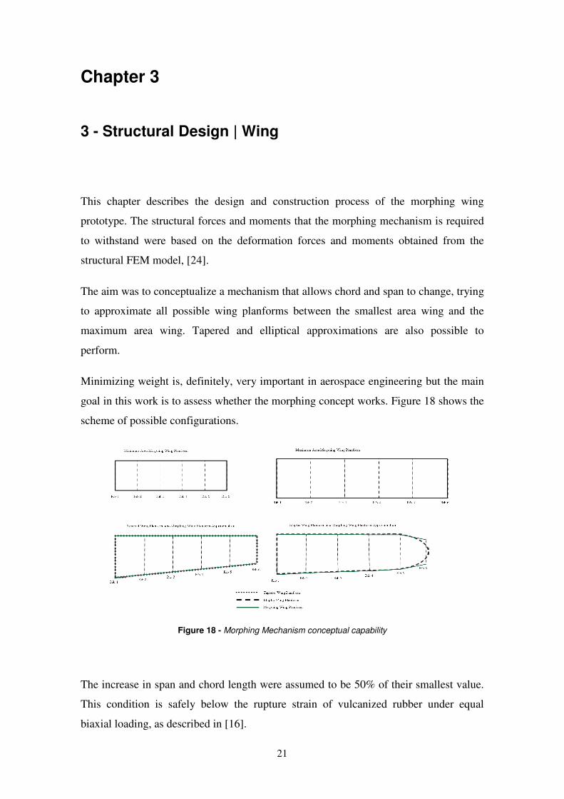
The aim was to conceptualize a mechanism that allows chord and span to change, trying
to approximate all possible wing planforms between the smallest area wing and the
maximum area wing. Tapered and elliptical approximations are also possible to
perform.
Minimizing weight is, definitely, very important in aerospace engineering but the main
goal in this work is to assess whether the morphing concept works. Figure 18 shows the
scheme of possible configurations.
Figure 18 - Morphing Mechanism conceptual capability
The increase in span and chord length were assumed to be 50% of their smallest value.
This condition is safely below the rupture strain of vulcanized rubber under equal
biaxial loading, as described in [16].
22
Each chord expansion mechanism is independently actuated and allows different
planform shapes to be obtained. At each rib section, independent servo-actuators are
used to extend the chord in the leading edge and in the trailing edge directions, so that
the quarter chord line can stay perpendicular to the wing root section.
3.1 - Morphing Mechanism Design for Wind Tunnel Testing
The structural FEM model produced the following results in terms of forces for a
morphing wing with the capabilities described in the previous chapter in its fully
extended position: the compressive force span wise is 8000N, compressive force chord
wise is 1500N and compressive force along thickness 250N.
These total forces refer to the full scale half wing, which in its retracted state is 1m long
span wise, 0.22m long chord wise and has a 0.002m thick rubber skin. In order to be
possible to fit the model in the wind tunnel testing facility the model has to be reduced
to half size. Therefore, span is 0.5m and chord is 0,11m. In order to reduce the actuation
forces needed to deform the wing skin, the skin thickness was reduced to 1mm.
The wind tunnel model is assumed to increase span and chord in the proportions used
for the full scale FEM model, which are 50% increase in span and chord dimensions.
Therefore, the stresses levels on the skin must be caused by the mechanism and are the
same of the full scale model.
For the normal stress in spanwise direction we have:
4
22
Fullscale
Halfscale
FullscaleFullscale
Halfscale
FullscaleFullscale
Fullscale
Halfscale
FullscaleFullscale
Fullscale
Fullscale
Fullscale
Fullscale
FF
scst
F
scst
F
sbst
F
A
F
=⇒=
=== σσ
Where σFullscale is the stress on the full scale component model, FFullscale is the force
actuating on the component, AFullscale in the area where the force is actuating, stFullsale is
the dimension chordwise of the component and scFullscale is the dimension along its
thickness. The subscripts “Half scale” correspond to the half scale model.
23
This means that the actuation forces in the half scale model with half skin thickness are
four times smaller relative to the full size model. The same reasoning can be used for
the stress in the chord wise direction. For the forces in the wing thickness direction, the
reasoning is slightly different since it depends on the wing sections’ relative thickness.
Assuming the final relative thickness of the half scale wing is approximately the same
as the full scale one, the compressive force in the thickness direction is reduced to half,
due to the reduction to half of the skin thickness.
Consequently, the sizing of the half scale wing model for wind tunnel testing is based
on the following actuation forces: span wise force is 2000N, chord wise force is 375N
and along the thickness the force is 125N.
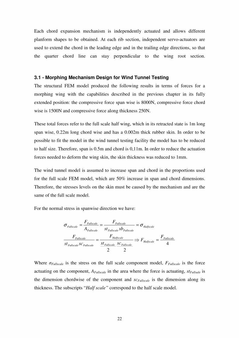
Since the half scale wing dimensions are very small, the thickness of the wing sections
doesn’t allow the design of an economically and technically feasible airfoil morphing
mechanism. Because of this, changing the wing airfoil thickness was discarded and only
chord and span changes were considered for the morphing mechanism design.
Naturally, changes in chord dimension changes the airfoil shape, but the airfoil
thickness cannot be actively altered for a given chord length.
As can be seen in figure 19, the airfoil at each rib will have three fixed shape sections
which will change their relative position along the chord axis as the total chord changes.
All the other requirements and assumptions made for the full scale FEM modelling are
taken into account in this new mechanism design.
Figure 19 - Designed rib extension mechanism: on the left extended, on the right retracted
3.1.1 - Mechanism Design
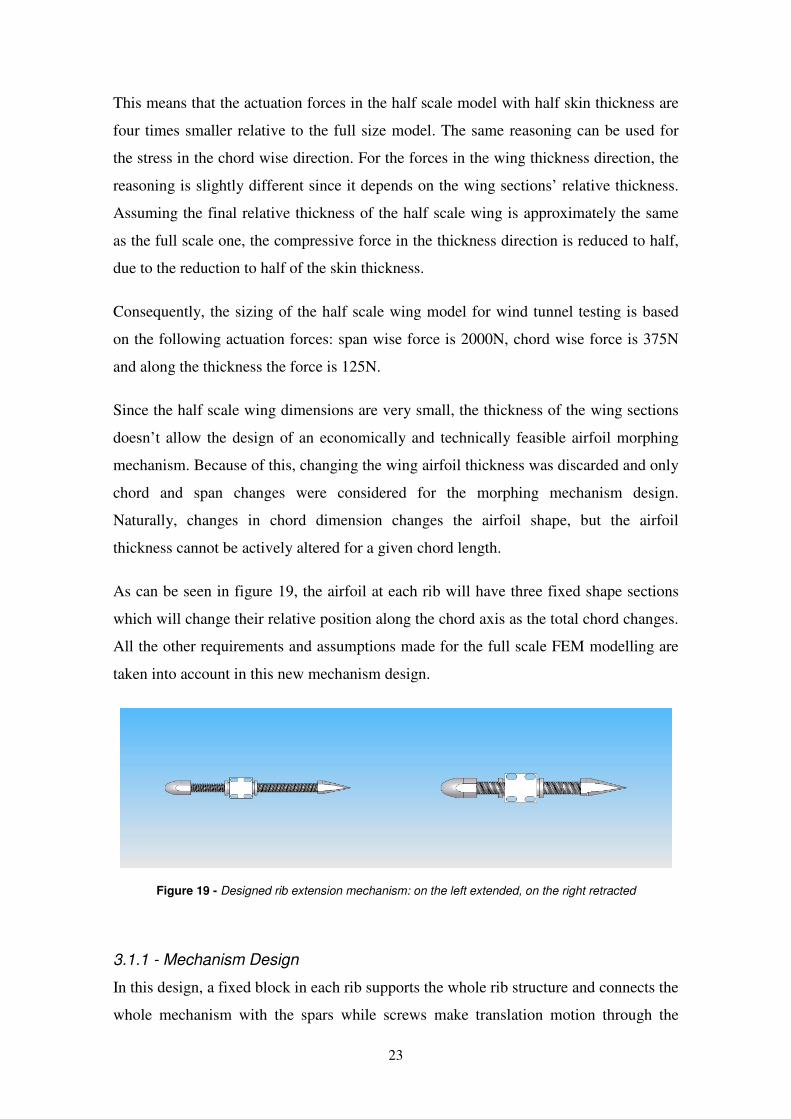
In this design, a fixed block in each rib supports the whole rib structure and connects the
whole mechanism with the spars while screws make translation motion through the
24
block core and stretch the wing skin. The block also supports the nuts which are mated
to the screws and are the only moving parts of the rib, since they are rotationally
actuated to cause the screws translation motion.
Figure 20 - Rib parts: on the left assembled rib expansion mechanism; on the right central block
Attached to the tip of the screws are the leading edge and trailing edge blocks. These
blocks have the function of shaping the wing skin at the leading and trailing edge,
respectively, and also serve as support elements for the leading and trailing edge
shaping beams, as can be seen in figure 20.
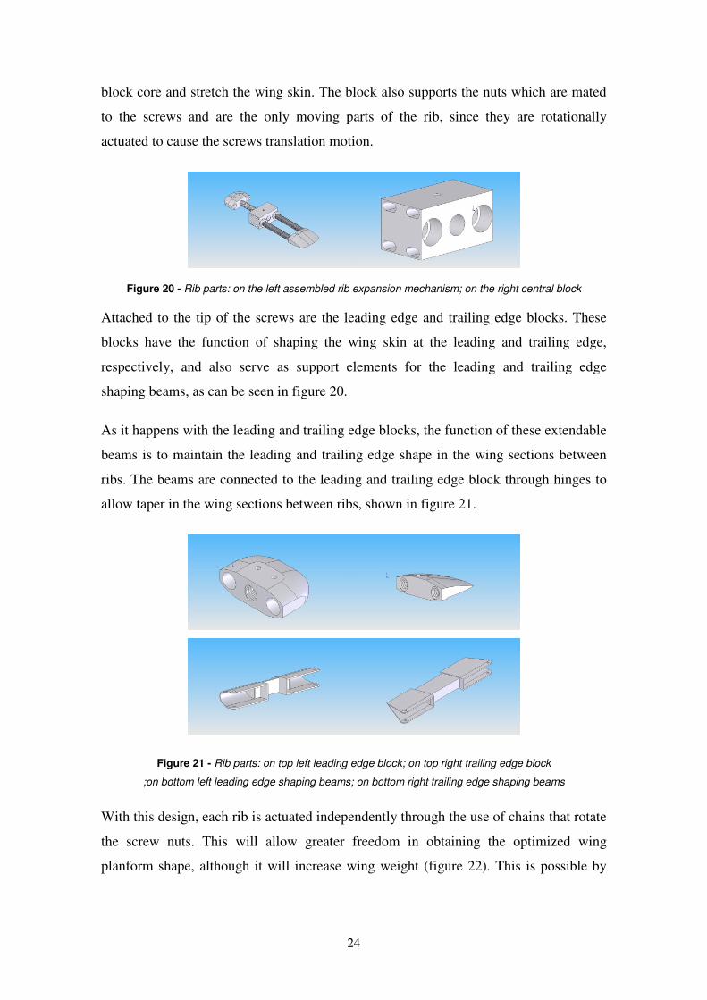
As it happens with the leading and trailing edge blocks, the function of these extendable
beams is to maintain the leading and trailing edge shape in the wing sections between
ribs. The beams are connected to the leading and trailing edge block through hinges to
allow taper in the wing sections between ribs, shown in figure 21.
Figure 21 - Rib parts: on top left leading edge block; on top right trailing edge block
;on bottom left leading edge shaping beams; on bottom right trailing edge shaping beams
With this design, each rib is actuated independently through the use of chains that rotate
the screw nuts. This will allow greater freedom in obtaining the optimized wing
planform shape, although it will increase wing weight (figure 22). This is possible by
25
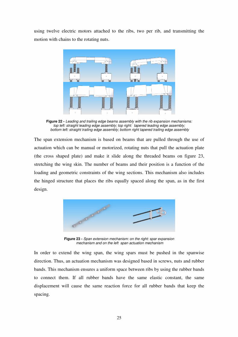
using twelve electric motors attached to the ribs, two per rib, and transmitting the
motion with chains to the rotating nuts.
Figure 22 - Leading and trailing edge beams assembly with the rib expansion mechanisms: top left: straight leading edge assembly; top right: tapered leading edge assembly;
bottom left: straight trailing edge assembly; bottom right tapered trailing edge assembly
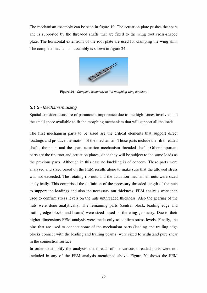
The span extension mechanism is based on beams that are pulled through the use of
actuation which can be manual or motorized, rotating nuts that pull the actuation plate
(the cross shaped plate) and make it slide along the threaded beams on figure 23,
stretching the wing skin. The number of beams and their position is a function of the
loading and geometric constraints of the wing sections. This mechanism also includes
the hinged structure that places the ribs equally spaced along the span, as in the first
design.
Figure 23 - Span extension mechanism: on the right: spar expansion mechanism and on the left span actuation mechanism
In order to extend the wing span, the wing spars must be pushed in the spanwise
direction. Thus, an actuation mechanism was designed based in screws, nuts and rubber
bands. This mechanism ensures a uniform space between ribs by using the rubber bands
to connect them. If all rubber bands have the same elastic constant, the same
displacement will cause the same reaction force for all rubber bands that keep the
spacing.
26
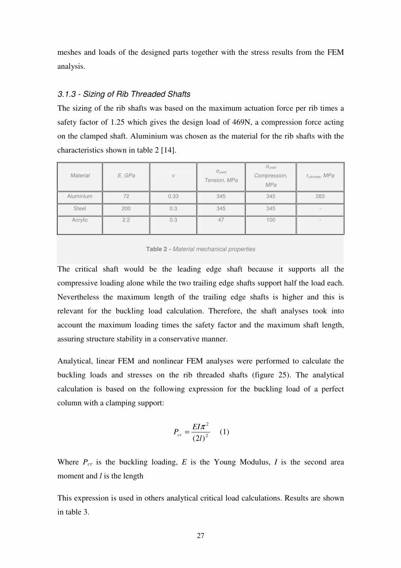
The mechanism assembly can be seen in figure 19. The actuation plate pushes the spars
and is supported by the threaded shafts that are fixed to the wing root cross-shaped
plate. The horizontal extensions of the root plate are used for clamping the wing skin.
The complete mechanism assembly is shown in figure 24.
Figure 24 - Complete assembly of the morphing wing structure
3.1.2 - Mechanism Sizing
Spatial considerations are of paramount importance due to the high forces involved and
the small space available to fit the morphing mechanism that will support all the loads.
The first mechanism parts to be sized are the critical elements that support direct
loadings and produce the motion of the mechanism. Those parts include the rib threaded
shafts, the spars and the spars actuation mechanism threaded shafts. Other important
parts are the tip, root and actuation plates, since they will be subject to the same loads as
the previous parts. Although in this case no buckling is of concern. These parts were
analyzed and sized based on the FEM results alone to make sure that the allowed stress
was not exceeded. The rotating rib nuts and the actuation mechanism nuts were sized
analytically. This comprised the definition of the necessary threaded length of the nuts
to support the loadings and also the necessary nut thickness. FEM analysis were then
used to confirm stress levels on the nuts unthreaded thickness. Also the gearing of the
nuts were done analytically. The remaining parts (central block, leading edge and
trailing edge blocks and beams) were sized based on the wing geometry. Due to their
higher dimensions FEM analysis were made only to confirm stress levels. Finally, the
pins that are used to connect some of the mechanism parts (leading and trailing edge
blocks connect with the leading and trailing beams) were sized to withstand pure shear
in the connection surface.
In order to simplify the analysis, the threads of the various threaded parts were not
included in any of the FEM analysis mentioned above. Figure 20 shows the FEM
27
meshes and loads of the designed parts together with the stress results from the FEM
analysis.
3.1.3 - Sizing of Rib Threaded Shafts
The sizing of the rib shafts was based on the maximum actuation force per rib times a
safety factor of 1.25 which gives the design load of 469N, a compression force acting
on the clamped shaft. Aluminium was chosen as the material for the rib shafts with the
characteristics shown in table 2 [14].
The critical shaft would be the leading edge shaft because it supports all the
compressive loading alone while the two trailing edge shafts support half the load each.
Nevertheless the maximum length of the trailing edge shafts is higher and this is
relevant for the buckling load calculation. Therefore, the shaft analyses took into
account the maximum loading times the safety factor and the maximum shaft length,
assuring structure stability in a conservative manner.
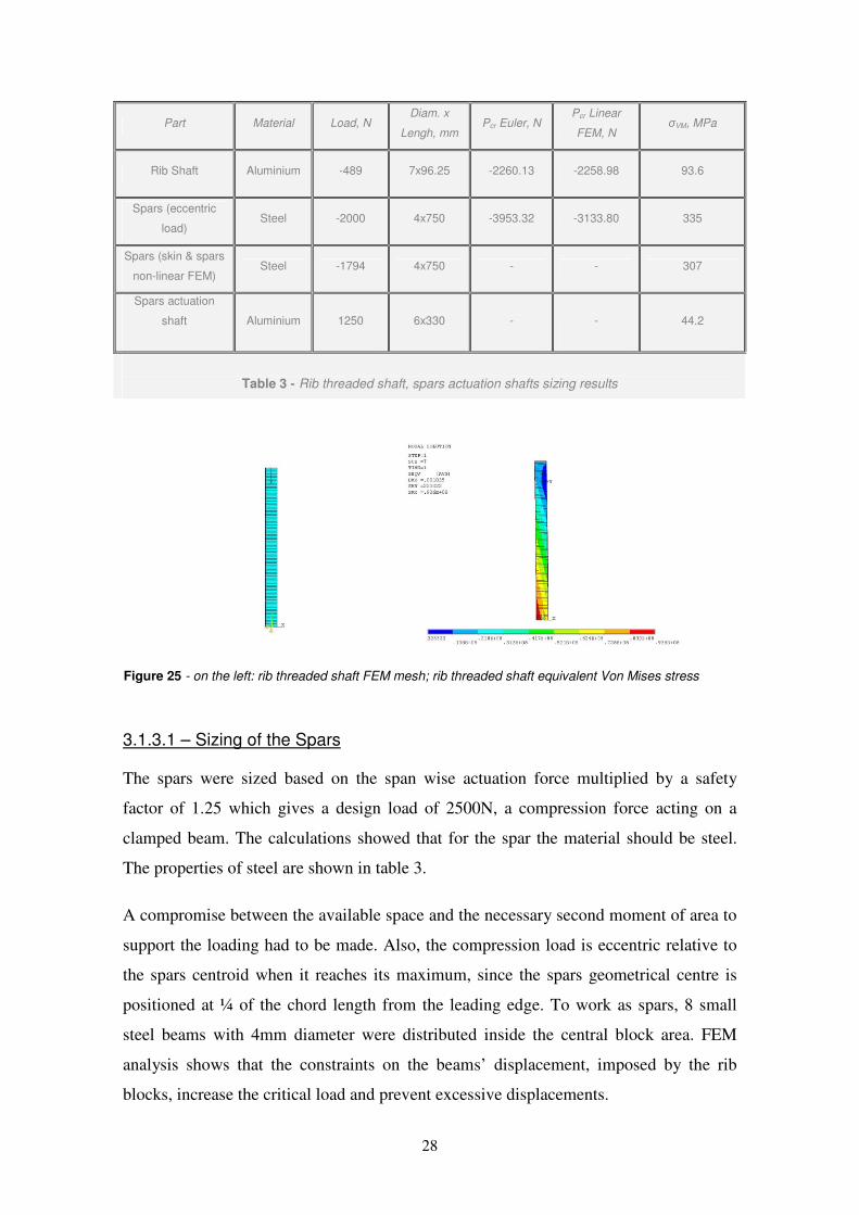
Analytical, linear FEM and nonlinear FEM analyses were performed to calculate the
buckling loads and stresses on the rib threaded shafts (figure 25). The analytical
calculation is based on the following expression for the buckling load of a perfect
column with a clamping support:
2
2
)2( l
EIPcr
π= (1)
Where Pcr is the buckling loading, E is the Young Modulus, I is the second area
moment and l is the length
This expression is used in others analytical critical load calculations. Results are shown
in table 3.
Material E, GPa ν σyield
Tension, MPa
σyield
Compression,
MPa
τultimate, MPa
Aluminium 72 0.33 345 345 283
Steel 200 0.3 345 345 -
Acrylic 2.2 0.3 47 100 -
Table 2 - Material mechanical properties
28
Part Material Load, N Diam. x
Lengh, mm Pcr Euler, N
Pcr Linear
FEM, N σVM, MPa
Rib Shaft Aluminium -489 7x96.25 -2260.13 -2258.98 93.6
Spars (eccentric
load) Steel -2000 4x750 -3953.32 -3133.80 335
Spars (skin & spars
non-linear FEM) Steel -1794 4x750 - - 307
Spars actuation
shaft Aluminium 1250 6x330 - - 44.2
Table 3 - Rib threaded shaft, spars actuation shafts sizing results
Figure 25 - on the left: rib threaded shaft FEM mesh; rib threaded shaft equivalent Von Mises stress
3.1.3.1 – Sizing of the Spars
The spars were sized based on the span wise actuation force multiplied by a safety
factor of 1.25 which gives a design load of 2500N, a compression force acting on a
clamped beam. The calculations showed that for the spar the material should be steel.
The properties of steel are shown in table 3.
A compromise between the available space and the necessary second moment of area to
support the loading had to be made. Also, the compression load is eccentric relative to
the spars centroid when it reaches its maximum, since the spars geometrical centre is
positioned at ¼ of the chord length from the leading edge. To work as spars, 8 small
steel beams with 4mm diameter were distributed inside the central block area. FEM
analysis shows that the constraints on the beams’ displacement, imposed by the rib
blocks, increase the critical load and prevent excessive displacements.
29
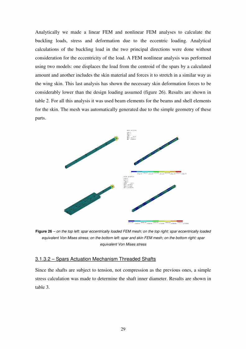
Analytically we made a linear FEM and nonlinear FEM analyses to calculate the
buckling loads, stress and deformation due to the eccentric loading. Analytical
calculations of the buckling load in the two principal directions were done without
consideration for the eccentricity of the load. A FEM nonlinear analysis was performed
using two models: one displaces the load from the centroid of the spars by a calculated
amount and another includes the skin material and forces it to stretch in a similar way as
the wing skin. This last analysis has shown the necessary skin deformation forces to be
considerably lower than the design loading assumed (figure 26). Results are shown in
table 2. For all this analysis it was used beam elements for the beams and shell elements
for the skin. The mesh was automatically generated due to the simple geometry of these
parts.
Figure 26 – on the top left: spar eccentrically loaded FEM mesh; on the top right: spar eccentrically loaded
equivalent Von Mises stress; on the bottom left: spar and skin FEM mesh; on the bottom right: spar
equivalent Von Mises stress
3.1.3.2 – Spars Actuation Mechanism Threaded Shafts
Since the shafts are subject to tension, not compression as the previous ones, a simple
stress calculation was made to determine the shaft inner diameter. Results are shown in
table 3.
30
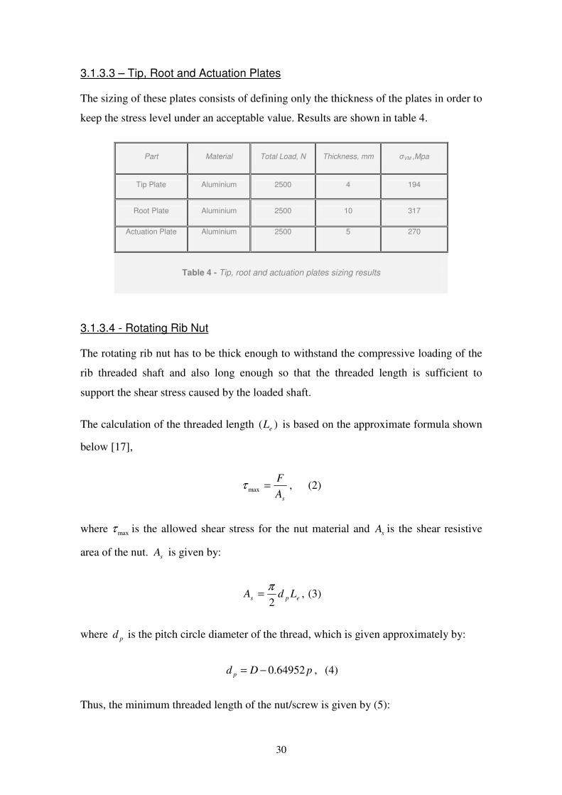
3.1.3.3 – Tip, Root and Actuation Plates
The sizing of these plates consists of defining only the thickness of the plates in order to
keep the stress level under an acceptable value. Results are shown in table 4.
Part Material Total Load, N Thickness, mm σVM ,Mpa
Tip Plate Aluminium 2500 4 194
Root Plate Aluminium 2500 10 317
Actuation Plate Aluminium 2500 5 270
Table 4 - Tip, root and actuation plates sizing results
3.1.3.4 - Rotating Rib Nut
The rotating rib nut has to be thick enough to withstand the compressive loading of the
rib threaded shaft and also long enough so that the threaded length is sufficient to
support the shear stress caused by the loaded shaft.
The calculation of the threaded length )( eL is based on the approximate formula shown
below [17],
sA
F=maxτ , (2)
where maxτ is the allowed shear stress for the nut material and sA is the shear resistive
area of the nut. sA is given by:
eps LdA2
π= , (3)
where pd is the pitch circle diameter of the thread, which is given approximately by:
pDd p 64952.0−= , (4)
Thus, the minimum threaded length of the nut/screw is given by (5):
31
max)64952.0(
2
τπ pD
FLe
−= , (5)
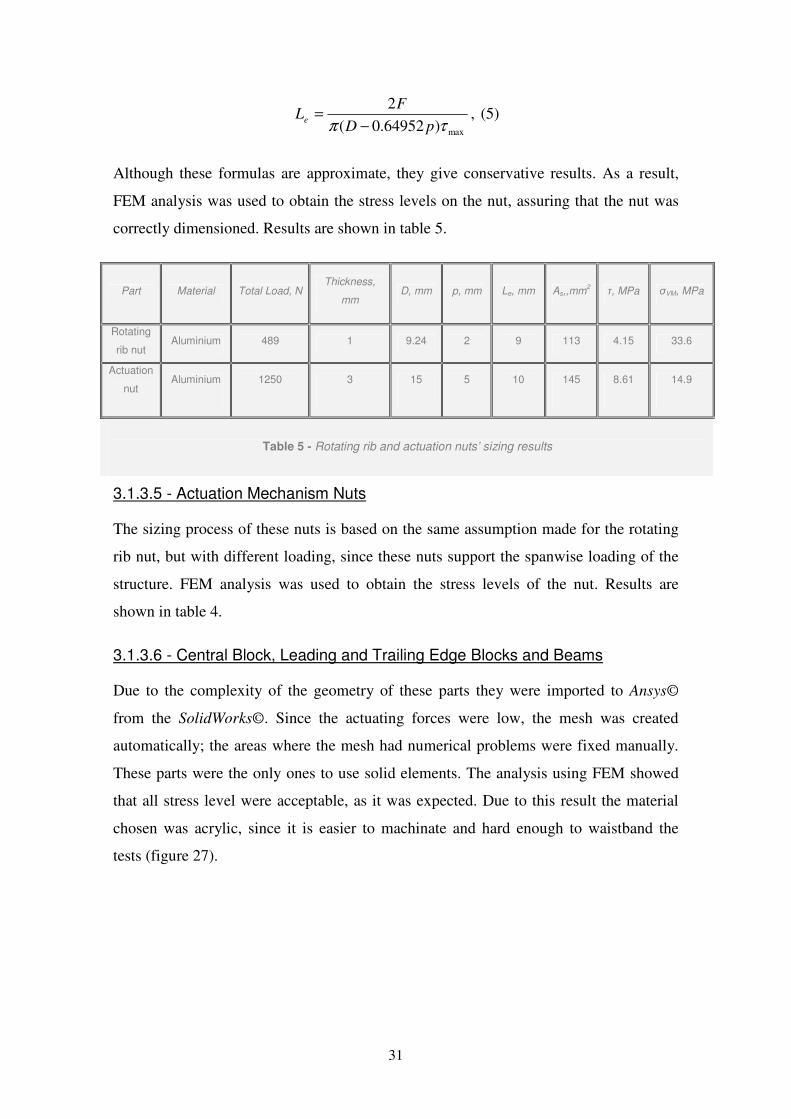
Although these formulas are approximate, they give conservative results. As a result,
FEM analysis was used to obtain the stress levels on the nut, assuring that the nut was
correctly dimensioned. Results are shown in table 5.
Part Material Total Load, N Thickness,
mm D, mm p, mm Le, mm As,,mm
2 τ, MPa σVM, MPa
Rotating
rib nut Aluminium 489 1 9.24 2 9 113 4.15 33.6
Actuation
nut Aluminium 1250 3 15 5 10 145 8.61 14.9
Table 5 - Rotating rib and actuation nuts’ sizing results
3.1.3.5 - Actuation Mechanism Nuts
The sizing process of these nuts is based on the same assumption made for the rotating
rib nut, but with different loading, since these nuts support the spanwise loading of the
structure. FEM analysis was used to obtain the stress levels of the nut. Results are
shown in table 4.
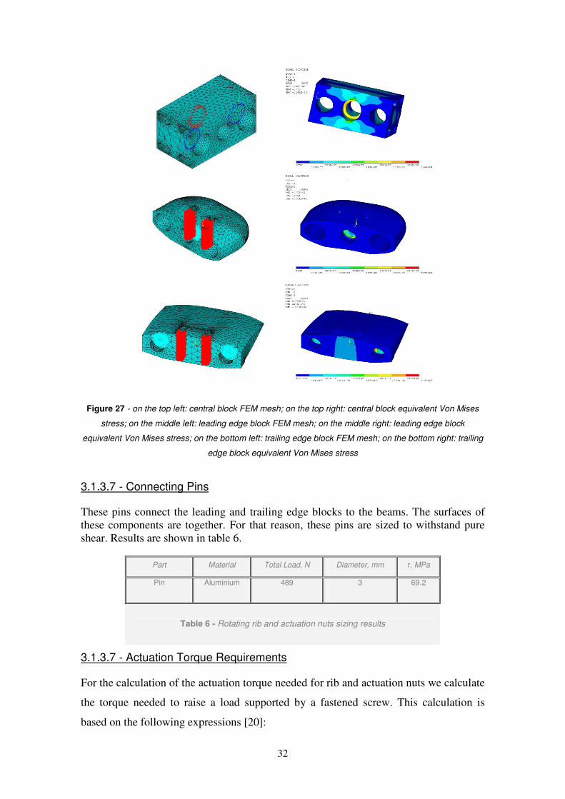
3.1.3.6 - Central Block, Leading and Trailing Edge Blocks and Beams
Due to the complexity of the geometry of these parts they were imported to Ansys©
from the SolidWorks©. Since the actuating forces were low, the mesh was created
automatically; the areas where the mesh had numerical problems were fixed manually.
These parts were the only ones to use solid elements. The analysis using FEM showed
that all stress level were acceptable, as it was expected. Due to this result the material
chosen was acrylic, since it is easier to machinate and hard enough to waistband the
tests (figure 27).
32
Figure 27 - on the top left: central block FEM mesh; on the top right: central block equivalent Von Mises
stress; on the middle left: leading edge block FEM mesh; on the middle right: leading edge block
equivalent Von Mises stress; on the bottom left: trailing edge block FEM mesh; on the bottom right: trailing
edge block equivalent Von Mises stress
3.1.3.7 - Connecting Pins
These pins connect the leading and trailing edge blocks to the beams. The surfaces of
these components are together. For that reason, these pins are sized to withstand pure
shear. Results are shown in table 6.
Part Material Total Load, N Diameter, mm τ, MPa
Pin Aluminium 489 3 69.2
Table 6 - Rotating rib and actuation nuts sizing results
3.1.3.7 - Actuation Torque Requirements
For the calculation of the actuation torque needed for rib and actuation nuts we calculate
the torque needed to raise a load supported by a fastened screw. This calculation is
based on the following expressions [20]:
33
'
)tan(2
cos
)tan(2
cos
2fFR
f
fd
FM m
n
n
p+
−
+
=
βθ
βθ
; (6)
= )cos(
2tantan
2β
θθan ; (7)
=
pd
pa
πβ tan ; (8)
The first term of the equation 6 represents the necessary torque to overcome the friction
between the threads of the screw and nut while the second term represents the necessary
torque to overcome the friction between the nut and the support surface where the nut
lies on. Equation 7 relates the angle between the reaction force and the axis of the screw
with the screw parameters θ and β , where θ is the thread profile angle and β is given
by equation 8. Results for the maximum torque are shown in table 7.
Part Material Total Load, N p, mm dp, mm θ, º f f' M, Nm
Rotating rib nut Aluminium 489 2 7.99 29 0.3 0.3 1.49
Actuation nut Aluminium 1250 5 9.24 29 0.3 0.3 5.47
Table 7 - Rotating rib and actuation nuts torque requirements
3.2 - Wing Manufacturing
Construction of the designed mechanism took place at I.S.T mechanical laboratory for
mechanical tooling. The main tool used was the milling machine. This machine has six
degrees of freedom, three rotations and three translation degrees and a digital position
indicator, which allows precision until centesimo of millimetre. This tool has revealed
to be very powerful, since its six degrees of freedom allowed to machine all the parts of
the wing structure and make the final assembly. The milling machine had recesses in the
gears, so the precision of the work was less than expected.

34
The available tooling machines allowed a limited precision in making holes and keeping
the alignment of the relatively great number of pieces to be manufactured. As a
consequence, the spar extension mechanism used to equalize the distance between ribs
as the span increases revealed to be extremely ineffective. Other affected parts that due
to alignment difficulties couldn’t withstand the loading were the expanding beams from
both the leading and trailing edge. The torsional stiffness of the eight spars was also
very low, because the tolerances involved were not able to constrain the eight spars to
act as a single spar. Finally, the friction force between the rotating rib nuts and the
central block was very high, both in the initial requirements and in the actual
mechanism assembly.
The screws and the rotating nuts were made by an exterior technician. We made the
order specifying the screws’ pitch and exterior diameter. For the nuts we specified
exterior dimensions to fit these nuts in the central blocks (figure 28).
Figure 28 - Shaft and rotating nut
All other parts were made by us, using the milling machine. The leading and trailing
edge beams were made with a folding machine. All the other parts of the wing were
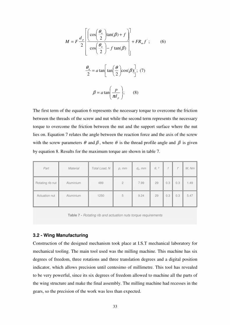
made in the milling machine (figure 29).
35
Figure 29 - Leading and trailing edge sliding beams
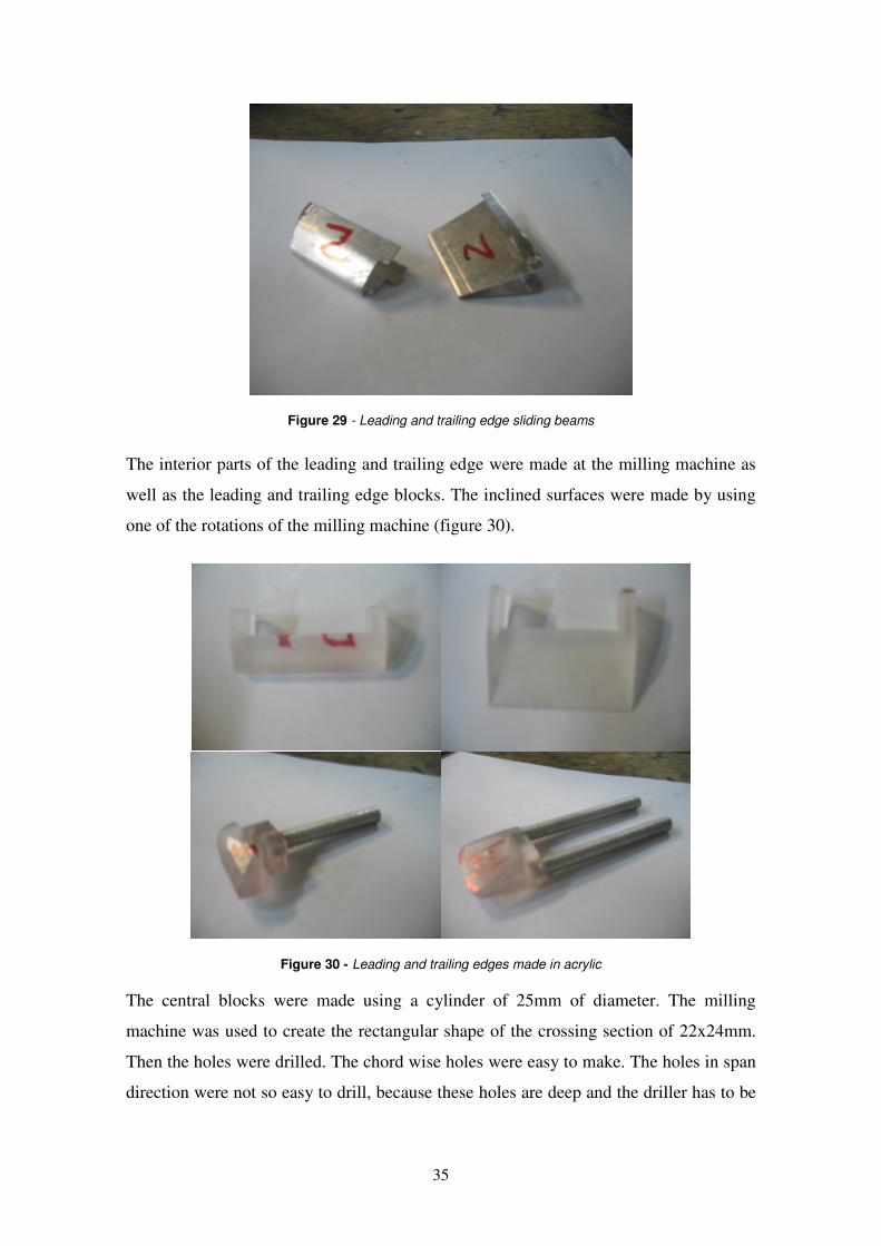
The interior parts of the leading and trailing edge were made at the milling machine as
well as the leading and trailing edge blocks. The inclined surfaces were made by using
one of the rotations of the milling machine (figure 30).
Figure 30 - Leading and trailing edges made in acrylic
The central blocks were made using a cylinder of 25mm of diameter. The milling
machine was used to create the rectangular shape of the crossing section of 22x24mm.
Then the holes were drilled. The chord wise holes were easy to make. The holes in span
direction were not so easy to drill, because these holes are deep and the driller has to be
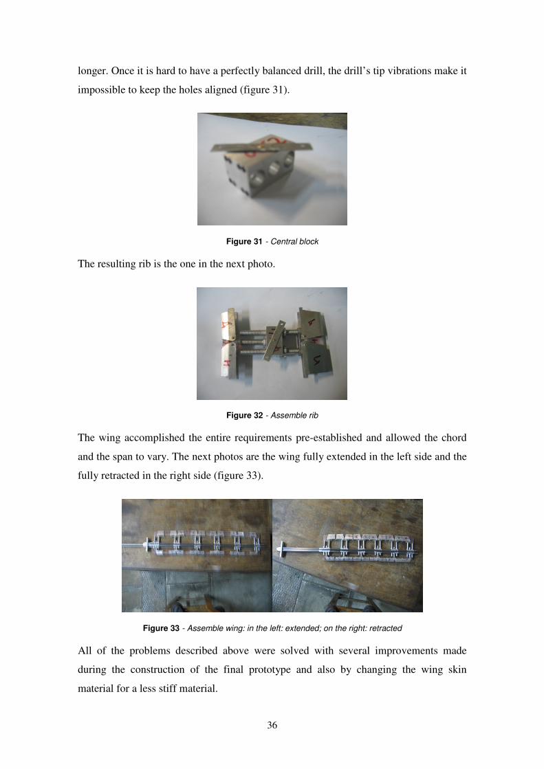
36
longer. Once it is hard to have a perfectly balanced drill, the drill’s tip vibrations make it
impossible to keep the holes aligned (figure 31).
Figure 31 - Central block
The resulting rib is the one in the next photo.
Figure 32 - Assemble rib
The wing accomplished the entire requirements pre-established and allowed the chord
and the span to vary. The next photos are the wing fully extended in the left side and the
fully retracted in the right side (figure 33).
Figure 33 - Assemble wing: in the left: extended; on the right: retracted
All of the problems described above were solved with several improvements made
during the construction of the final prototype and also by changing the wing skin
material for a less stiff material.
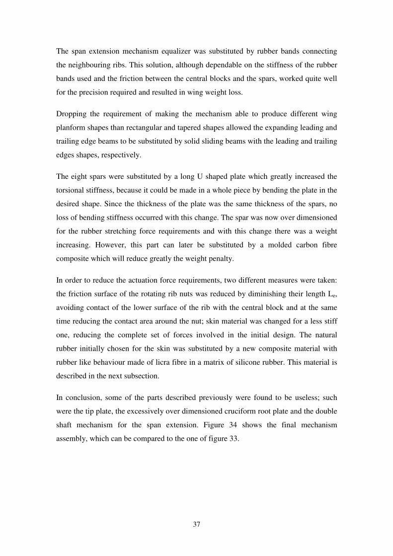
37
The span extension mechanism equalizer was substituted by rubber bands connecting
the neighbouring ribs. This solution, although dependable on the stiffness of the rubber
bands used and the friction between the central blocks and the spars, worked quite well
for the precision required and resulted in wing weight loss.
Dropping the requirement of making the mechanism able to produce different wing
planform shapes than rectangular and tapered shapes allowed the expanding leading and
trailing edge beams to be substituted by solid sliding beams with the leading and trailing
edges shapes, respectively.
The eight spars were substituted by a long U shaped plate which greatly increased the
torsional stiffness, because it could be made in a whole piece by bending the plate in the
desired shape. Since the thickness of the plate was the same thickness of the spars, no
loss of bending stiffness occurred with this change. The spar was now over dimensioned
for the rubber stretching force requirements and with this change there was a weight
increasing. However, this part can later be substituted by a molded carbon fibre
composite which will reduce greatly the weight penalty.
In order to reduce the actuation force requirements, two different measures were taken:
the friction surface of the rotating rib nuts was reduced by diminishing their length Le,
avoiding contact of the lower surface of the rib with the central block and at the same
time reducing the contact area around the nut; skin material was changed for a less stiff
one, reducing the complete set of forces involved in the initial design. The natural
rubber initially chosen for the skin was substituted by a new composite material with
rubber like behaviour made of licra fibre in a matrix of silicone rubber. This material is
described in the next subsection.
In conclusion, some of the parts described previously were found to be useless; such
were the tip plate, the excessively over dimensioned cruciform root plate and the double
shaft mechanism for the span extension. Figure 34 shows the final mechanism
assembly, which can be compared to the one of figure 33.
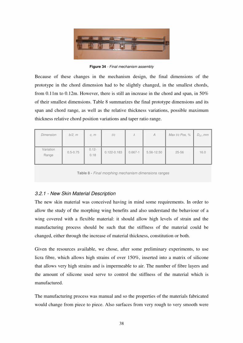
38
Figure 34 - Final mechanism assembly
Because of these changes in the mechanism design, the final dimensions of the
prototype in the chord dimension had to be slightly changed, in the smallest chords,
from 0.11m to 0.12m. However, there is still an increase in the chord and span, in 50%
of their smallest dimensions. Table 8 summarizes the final prototype dimensions and its
span and chord range, as well as the relative thickness variations, possible maximum
thickness relative chord position variations and taper ratio range.
Dimension b/2, m c, m t/c λ A Max t/c Pos, % DLE ,mm
Variation
Range 0.5-0.75
0.12-
0.18 0.122-0.183 0.667-1 5.56-12.50 25-56 16.0
Table 8 - Final morphing mechanism dimensions ranges
3.2.1 - New Skin Material Description
The new skin material was conceived having in mind some requirements. In order to
allow the study of the morphing wing benefits and also understand the behaviour of a
wing covered with a flexible material: it should allow high levels of strain and the
manufacturing process should be such that the stiffness of the material could be
changed, either through the increase of material thickness, constitution or both.
Given the resources available, we chose, after some preliminary experiments, to use
licra fibre, which allows high strains of over 150%, inserted into a matrix of silicone
that allows very high strains and is impermeable to air. The number of fibre layers and
the amount of silicone used serve to control the stiffness of the material which is
manufactured.
The manufacturing process was manual and so the properties of the materials fabricated
would change from piece to piece. Also surfaces from very rough to very smooth were
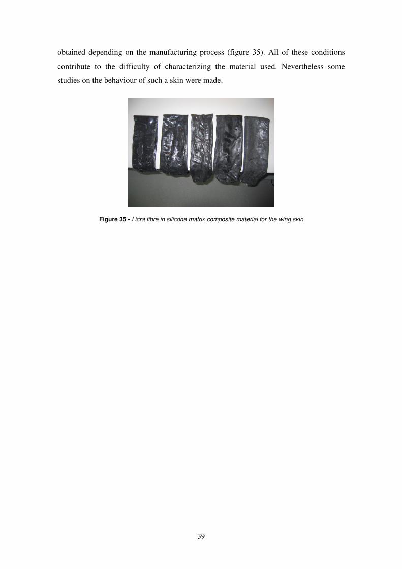
39
obtained depending on the manufacturing process (figure 35). All of these conditions
contribute to the difficulty of characterizing the material used. Nevertheless some
studies on the behaviour of such a skin were made.
Figure 35 - Licra fibre in silicone matrix composite material for the wing skin
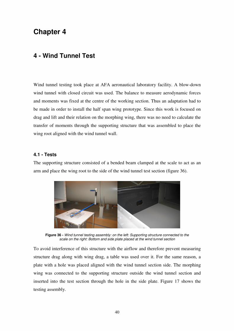
40
Chapter 4
4 - Wind Tunnel Test
Wind tunnel testing took place at AFA aeronautical laboratory facility. A blow-down
wind tunnel with closed circuit was used. The balance to measure aerodynamic forces
and moments was fixed at the centre of the working section. Thus an adaptation had to
be made in order to install the half span wing prototype. Since this work is focused on
drag and lift and their relation on the morphing wing, there was no need to calculate the
transfer of moments through the supporting structure that was assembled to place the
wing root aligned with the wind tunnel wall.
4.1 - Tests
The supporting structure consisted of a bended beam clamped at the scale to act as an
arm and place the wing root to the side of the wind tunnel test section (figure 36).
Figure 36 - Wind tunnel testing assembly: on the left: Supporting structure connected to the scale on the right: Bottom and side plate placed at the wind tunnel section
To avoid interference of this structure with the airflow and therefore prevent measuring
structure drag along with wing drag, a table was used over it. For the same reason, a
plate with a hole was placed aligned with the wind tunnel section side. The morphing
wing was connected to the supporting structure outside the wind tunnel section and
inserted into the test section through the hole in the side plate. Figure 17 shows the
testing assembly.
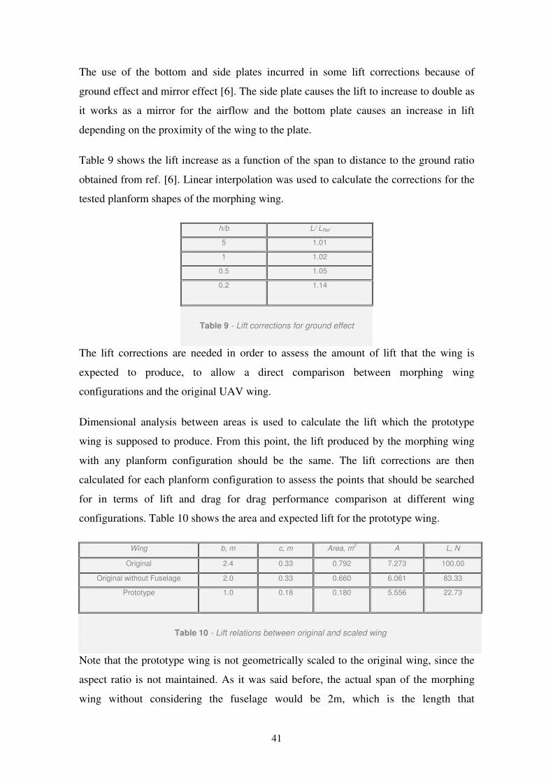
41
The use of the bottom and side plates incurred in some lift corrections because of
ground effect and mirror effect [6]. The side plate causes the lift to increase to double as
it works as a mirror for the airflow and the bottom plate causes an increase in lift
depending on the proximity of the wing to the plate.
Table 9 shows the lift increase as a function of the span to distance to the ground ratio
obtained from ref. [6]. Linear interpolation was used to calculate the corrections for the
tested planform shapes of the morphing wing.
h/b L/ LRef
5 1.01
1 1.02
0.5 1.05
0.2 1.14
Table 9 - Lift corrections for ground effect
The lift corrections are needed in order to assess the amount of lift that the wing is
expected to produce, to allow a direct comparison between morphing wing
configurations and the original UAV wing.
Dimensional analysis between areas is used to calculate the lift which the prototype
wing is supposed to produce. From this point, the lift produced by the morphing wing
with any planform configuration should be the same. The lift corrections are then
calculated for each planform configuration to assess the points that should be searched
for in terms of lift and drag for drag performance comparison at different wing
configurations. Table 10 shows the area and expected lift for the prototype wing.
Wing b, m c, m Area, m2 A L, N
Original 2.4 0.33 0.792 7.273 100.00
Original without Fuselage 2.0 0.33 0.660 6.061 83.33
Prototype 1.0 0.18 0.180 5.556 22.73
Table 10 - Lift relations between original and scaled wing
Note that the prototype wing is not geometrically scaled to the original wing, since the
aspect ratio is not maintained. As it was said before, the actual span of the morphing
wing without considering the fuselage would be 2m, which is the length that
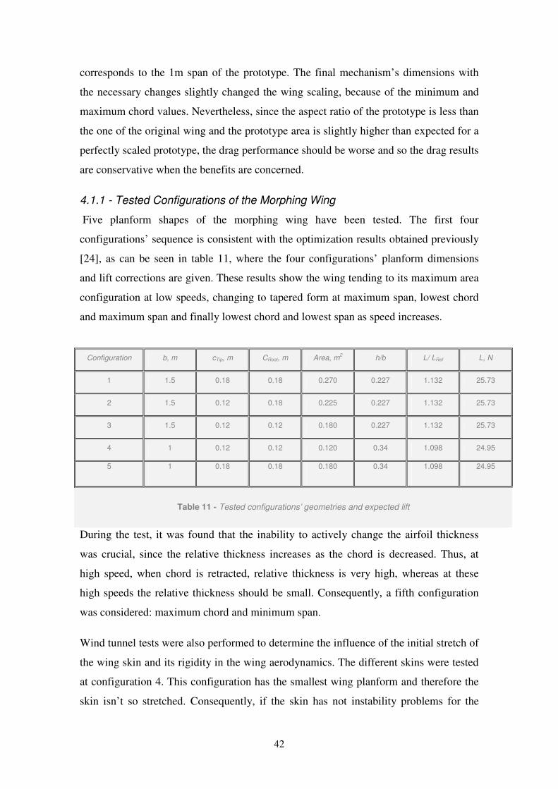
42
corresponds to the 1m span of the prototype. The final mechanism’s dimensions with
the necessary changes slightly changed the wing scaling, because of the minimum and
maximum chord values. Nevertheless, since the aspect ratio of the prototype is less than
the one of the original wing and the prototype area is slightly higher than expected for a
perfectly scaled prototype, the drag performance should be worse and so the drag results
are conservative when the benefits are concerned.
4.1.1 - Tested Configurations of the Morphing Wing
Five planform shapes of the morphing wing have been tested. The first four
configurations’ sequence is consistent with the optimization results obtained previously
[24], as can be seen in table 11, where the four configurations’ planform dimensions
and lift corrections are given. These results show the wing tending to its maximum area
configuration at low speeds, changing to tapered form at maximum span, lowest chord
and maximum span and finally lowest chord and lowest span as speed increases.
During the test, it was found that the inability to actively change the airfoil thickness
was crucial, since the relative thickness increases as the chord is decreased. Thus, at
high speed, when chord is retracted, relative thickness is very high, whereas at these
high speeds the relative thickness should be small. Consequently, a fifth configuration
was considered: maximum chord and minimum span.
Wind tunnel tests were also performed to determine the influence of the initial stretch of
the wing skin and its rigidity in the wing aerodynamics. The different skins were tested
at configuration 4. This configuration has the smallest wing planform and therefore the
skin isn’t so stretched. Consequently, if the skin has not instability problems for the
Configuration b, m cTip, m CRoot, m Area, m2 h/b L/ LRef L, N
1 1.5 0.18 0.18 0.270 0.227 1.132 25.73
2 1.5 0.12 0.18 0.225 0.227 1.132 25.73
3 1.5 0.12 0.12 0.180 0.227 1.132 25.73
4 1 0.12 0.12 0.120 0.34 1.098 24.95
5 1 0.18 0.18 0.180 0.34 1.098 24.95
Table 11 - Tested configurations’ geometries and expected lift
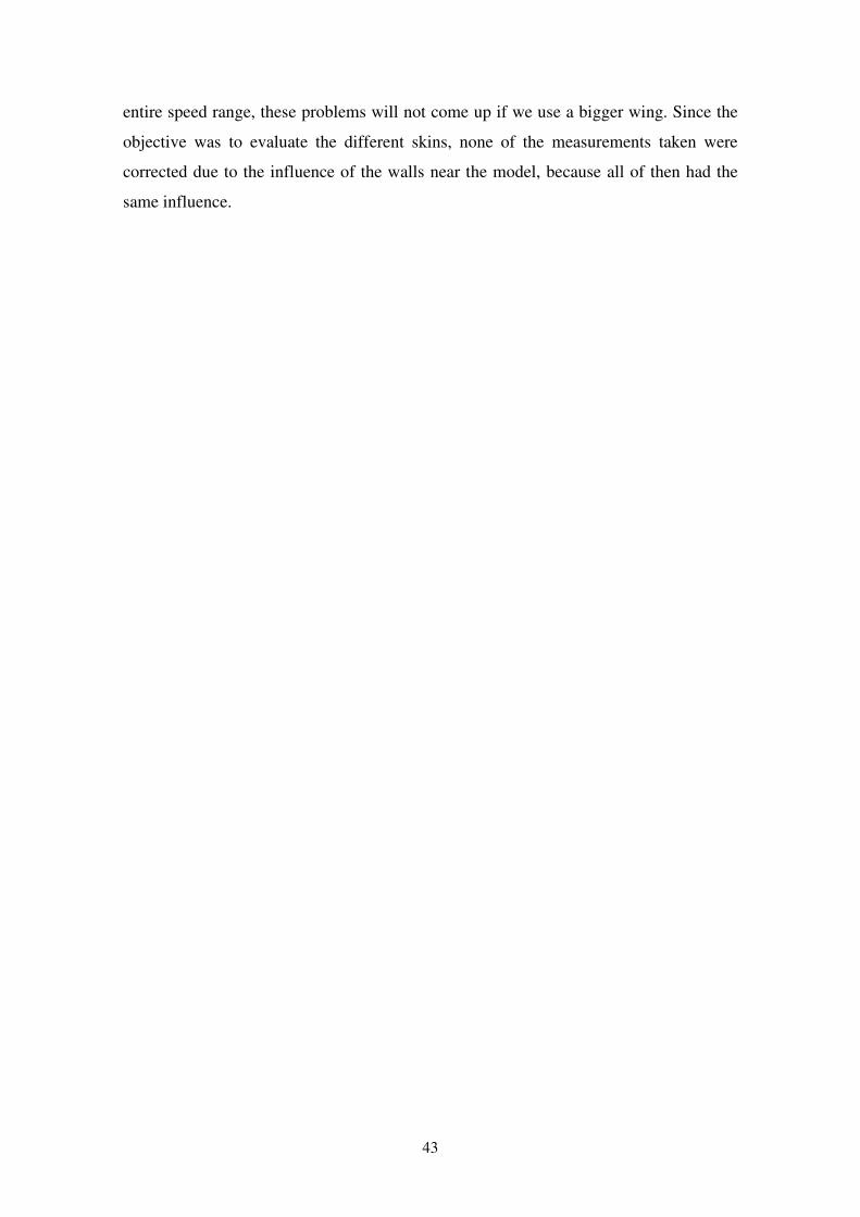
43
entire speed range, these problems will not come up if we use a bigger wing. Since the
objective was to evaluate the different skins, none of the measurements taken were
corrected due to the influence of the walls near the model, because all of then had the
same influence.

44
Chapter 5
5 - Results Analysis
In this chapter results obtained on the wind tunnel tests are described and also analysed.
First the different skins results are presented to validate which has the best behaviour at
different speeds. Then the different configurations results are presented
5.1 - Detail Analysis
During the tests, several observations were made: the flexible skin deforms due to the
pressure field of the flow; the deformation becomes higher at higher airspeeds and as
the speed increases the pressure decreases carrying to higher deformations; over certain
airspeed the vibration of the skin produced noise and cyclic deformations.
These observations leaded us to the study of the influence of the skin stretch and skin
stiffness, on the aerodynamics of the flexible skin wing. Therefore, using the morphing
wing at configuration four, experiments were made with the wing stretched at two
different expansions and also with a skin made of a double number of lycra fibre layers
and with a double overall thickness. Table 12 presents the skins characteristics.
Skin Spanwise
stretch
Chordwise
stretch
Nº of licra fibre
layers Thickness, mm
1 1.05 1.325 2 1
2 1.29 1.25 2 1
3 1.05 1.325 4 2
Table 12 - Tested skins characteristics
The results shown on the graphics of the figures 37 and 38 correspond to the
configuration 4 with three different skins. The charts are lift coefficient (CL) versus
angle of attack (AoA) and Drag (D) versus Lift (L), for the different airspeeds (U) for
which the tests were performed.
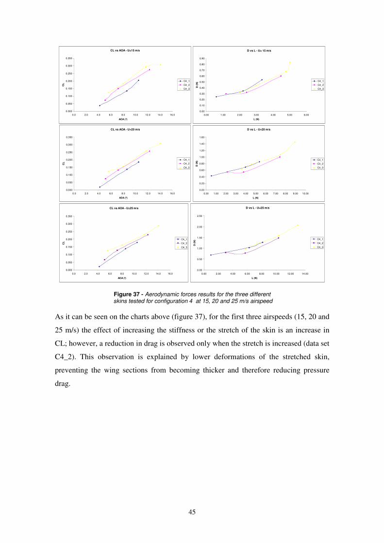
45
CL vs AOA - U=15 m/s
0.000
0.050
0.100
0.150
0.200
0.250
0.300
0.350
0.0 2.0 4.0 6.0 8.0 10.0 12.0 14.0 16.0
AOA (º)
CL
C4_1
C4_2
C4_3
D vs L - U= 15 m/s
0.00
0.10
0.20
0.30
0.40
0.50
0.60
0.70
0.80
0.90
0.00 1.00 2.00 3.00 4.00 5.00 6.00
L (N)
D (
N) C4_1
C4_2
C4_3
CL vs AOA - U=20 m/s
0.000
0.050
0.100
0.150
0.200
0.250
0.300
0.350
0.0 2.0 4.0 6.0 8.0 10.0 12.0 14.0 16.0
AOA (º)
CL
C4_1
C4_2
C4_3
D vs L - U=20 m/s
0.00
0.20
0.40
0.60
0.80
1.00
1.20
1.40
1.60
0.00 1.00 2.00 3.00 4.00 5.00 6.00 7.00 8.00 9.00 10.00
L (N)D
(N
) C4_1
C4_2
C4_3
CL vs AOA - U=25 m/s
0.000
0.050
0.100
0.150
0.200
0.250
0.300
0.350
0.0 2.0 4.0 6.0 8.0 10.0 12.0 14.0 16.0
AOA (º)
CL
C4_1
C4_2
C4_3
D vs L - U=25 m/s
0.00
0.50
1.00
1.50
2.00
2.50
0.00 2.00 4.00 6.00 8.00 10.00 12.00 14.00
L (N)
D (
N) C4_1
C4_2
C4_3
Figure 37 - Aerodynamic forces results for the three different skins tested for configuration 4 at 15, 20 and 25 m/s airspeed
As it can be seen on the charts above (figure 37), for the first three airspeeds (15, 20 and
25 m/s) the effect of increasing the stiffness or the stretch of the skin is an increase in
CL; however, a reduction in drag is observed only when the stretch is increased (data set
C4_2). This observation is explained by lower deformations of the stretched skin,
preventing the wing sections from becoming thicker and therefore reducing pressure
drag.
46
CL vs AOA - U=35 m/s
0.000
0.050
0.100
0.150
0.200
0.250
0.300
0.0 2.0 4.0 6.0 8.0 10.0 12.0 14.0 16.0
AOA (º)
CL
C4_1
C4_2
C4_3
D vs L - U=35 m/s
0.00
0.50
1.00
1.50
2.00
2.50
3.00
3.50
4.00
4.50
0.00 5.00 10.00 15.00 20.00 25.00
L (N)
D (
N) C4_1
C4_2
C4_3
CL vs AOA - U=40 m/s
0.000
0.050
0.100
0.150
0.200
0.250
0.300
0.0 2.0 4.0 6.0 8.0 10.0 12.0 14.0 16.0
AOA (º)
CL
C4_1
C4_2
C4_3
D vs L - U=40 m/s
0.00
1.00
2.00
3.00
4.00
5.00
6.00
7.00
8.00
0.00 5.00 10.00 15.00 20.00 25.00 30.00 35.00
L (N)D
(N
) C4_1
C4_2
C4_3
Figure 38 - Aerodynamic forces results for the tested skins at 35 and 40 m/s airspeed
When looking at the D versus L curves at the referred velocities, it is observed that for
the same stretch (data sets C4_1 and C4_3) the values of drag are similar for the same
lift values. The increase in the thickness of the airfoil due to the thicker skin may
explain the higher CL observed at the same AOA when comparing with the thinner
skin. The advantage of having a stiffer skin is to have the same lift at a lower AOA.
Between airspeeds of 35 and 40 m/s (figure 38) the occurrence of skin instability was
observed for skins 1 and 2, which did not happen with skin 3. This occurrence is visible
in the difference of slope of the CL versus AOA curves (CLα). For the thicker skin CLα
is lower, although D versus L curve shows that the skin instability happens sooner in
thinner skins.
In figure 39 is shown the influence of airspeed in CLα and the drag coefficient (CD) for
skin 3. It can be verified that as speed increases, CLα decreases while the CD varies
without showing a clear tendency. This is caused by the deformation of the skin, which
alters the wing sections and reduces the wing’s efficiency. Similar trends were verified
for skins 1 and 2.
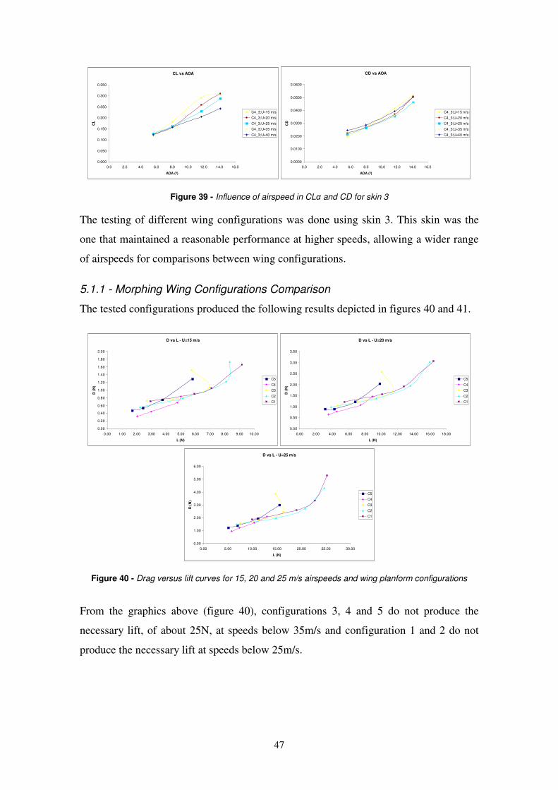
47
CL vs AOA
0.000
0.050
0.100
0.150
0.200
0.250
0.300
0.350
0.0 2.0 4.0 6.0 8.0 10.0 12.0 14.0 16.0
AOA (º)
CL
C4_3;U=15 m/s
C4_3;U=20 m/s
C4_3;U=25 m/s
C4_3;U=35 m/s
C4_3;U=40 m/s
CD vs AOA
0.0000
0.0100
0.0200
0.0300
0.0400
0.0500
0.0600
0.0 2.0 4.0 6.0 8.0 10.0 12.0 14.0 16.0
AOA (º)
CD
C4_3;U=15 m/s
C4_3;U=20 m/s
C4_3;U=25 m/s
C4_3;U=35 m/s
C4_3;U=40 m/s
Figure 39 - Influence of airspeed in CLα and CD for skin 3
The testing of different wing configurations was done using skin 3. This skin was the
one that maintained a reasonable performance at higher speeds, allowing a wider range
of airspeeds for comparisons between wing configurations.
5.1.1 - Morphing Wing Configurations Comparison
The tested configurations produced the following results depicted in figures 40 and 41.
D vs L - U=15 m/s
0.00
0.20
0.40
0.60
0.80
1.00
1.20
1.40
1.60
1.80
2.00
0.00 1.00 2.00 3.00 4.00 5.00 6.00 7.00 8.00 9.00 10.00
L (N)
D (
N)
C5
C4
C3
C2
C1
D vs L - U=20 m/s
0.00
0.50
1.00
1.50
2.00
2.50
3.00
3.50
0.00 2.00 4.00 6.00 8.00 10.00 12.00 14.00 16.00 18.00
L (N)
D (
N)
C5
C4
C3
C2
C1
D vs L - U=25 m/s
0.00
1.00
2.00
3.00
4.00
5.00
6.00
0.00 5.00 10.00 15.00 20.00 25.00 30.00
L (N)
D (
N)
C5
C4
C3
C2
C1
Figure 40 - Drag versus lift curves for 15, 20 and 25 m/s airspeeds and wing planform configurations
From the graphics above (figure 40), configurations 3, 4 and 5 do not produce the
necessary lift, of about 25N, at speeds below 35m/s and configuration 1 and 2 do not
produce the necessary lift at speeds below 25m/s.
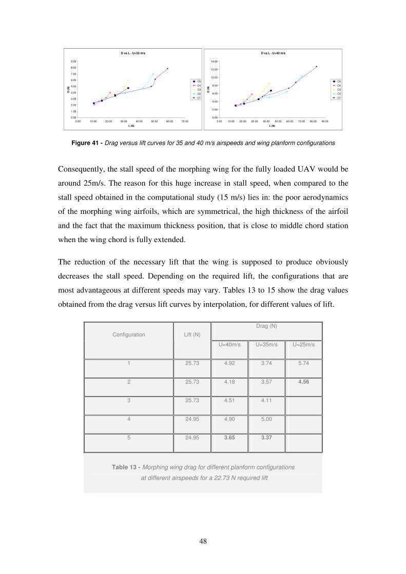
48
D vs L - U=35 m/s
0.00
1.00
2.00
3.00
4.00
5.00
6.00
7.00
8.00
9.00
0.00 10.00 20.00 30.00 40.00 50.00 60.00 70.00
L (N)
D (
N)
C5
C4
C3
C2
C1
D vs L - U=40 m/s
0.00
2.00
4.00
6.00
8.00
10.00
12.00
14.00
0.00 10.00 20.00 30.00 40.00 50.00 60.00 70.00 80.00 90.00
L (N)
D (
N)
C5
C4
C3
C2
C1
Figure 41 - Drag versus lift curves for 35 and 40 m/s airspeeds and wing planform configurations
Consequently, the stall speed of the morphing wing for the fully loaded UAV would be
around 25m/s. The reason for this huge increase in stall speed, when compared to the
stall speed obtained in the computational study (15 m/s) lies in: the poor aerodynamics
of the morphing wing airfoils, which are symmetrical, the high thickness of the airfoil
and the fact that the maximum thickness position, that is close to middle chord station
when the wing chord is fully extended.
The reduction of the necessary lift that the wing is supposed to produce obviously
decreases the stall speed. Depending on the required lift, the configurations that are
most advantageous at different speeds may vary. Tables 13 to 15 show the drag values
obtained from the drag versus lift curves by interpolation, for different values of lift.
Drag (N)
Configuration Lift (N)
U=40m/s U=35m/s U=25m/s
1 25.73 4.92 3.74 5.74
2 25.73 4.18 3.57 4.56
3 25.73 4.51 4.11
4 24.95 4.90 5.00
5 24.95 3.65 3.37
Table 13 - Morphing wing drag for different planform configurations
at different airspeeds for a 22.73 N required lift
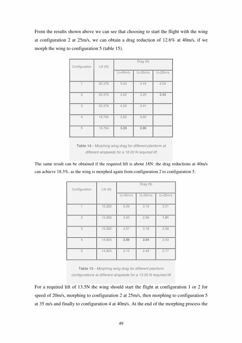
49
From the results shown above we can see that choosing to start the flight with the wing
at configuration 2 at 25m/s, we can obtain a drag reduction of 12.6% at 40m/s, if we
morph the wing to configuration 5 (table 15).
Drag (N)
Configuration Lift (N)
U=40m/s U=35m/s U=25m/s
1 20.376 5.04 3.44 2.54
2 20.376 4.02 3.25 2.43
3 20.376 4.29 3.41
4 19.764 3.62 3.60
5 19.764 3.28 2.86
Table 14 - Morphing wing drag for different planform at
different airspeeds for a 18.00 N required lift
The same result can be obtained if the required lift is about 18N: the drag reductions at 40m/s
can achieve 18.3%, as the wing is morphed again from configuration 2 to configuration 5.
Drag (N)
Configuration Lift (N)
U=40m/s U=35m/s U=25m/s
1 15.282 5.29 3.16 2.21
2 15.282 3.93 2.96 1.91
3 15.282 4.57 3.18 2.28
4 14.823 2.89 2.64 2.43
5 14.823 3.10 2.49 2.77
Table 15 - Morphing wing drag for different planform
configurations at different airspeeds for a 13.50 N required lift
For a required lift of 13.5N the wing should start the flight at configuration 1 or 2 for
speed of 20m/s, morphing to configuration 2 at 25m/s, then morphing to configuration 5
at 35 m/s and finally to configuration 4 at 40m/s. At the end of the morphing process the
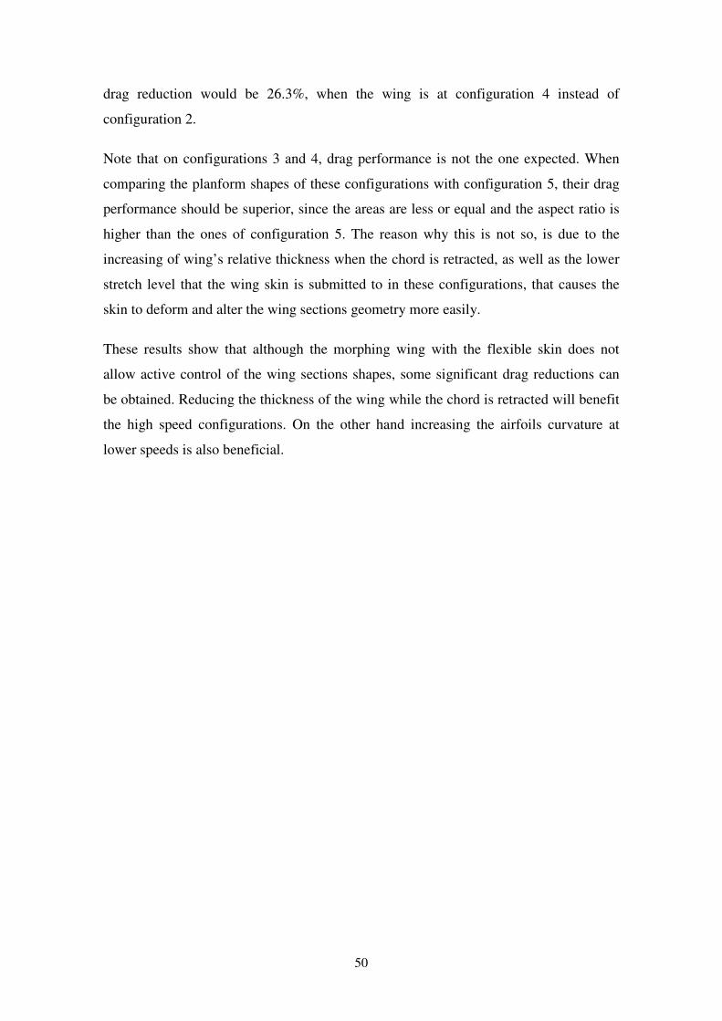
50
drag reduction would be 26.3%, when the wing is at configuration 4 instead of
configuration 2.
Note that on configurations 3 and 4, drag performance is not the one expected. When
comparing the planform shapes of these configurations with configuration 5, their drag
performance should be superior, since the areas are less or equal and the aspect ratio is
higher than the ones of configuration 5. The reason why this is not so, is due to the
increasing of wing’s relative thickness when the chord is retracted, as well as the lower
stretch level that the wing skin is submitted to in these configurations, that causes the
skin to deform and alter the wing sections geometry more easily.
These results show that although the morphing wing with the flexible skin does not
allow active control of the wing sections shapes, some significant drag reductions can
be obtained. Reducing the thickness of the wing while the chord is retracted will benefit
the high speed configurations. On the other hand increasing the airfoils curvature at
lower speeds is also beneficial.
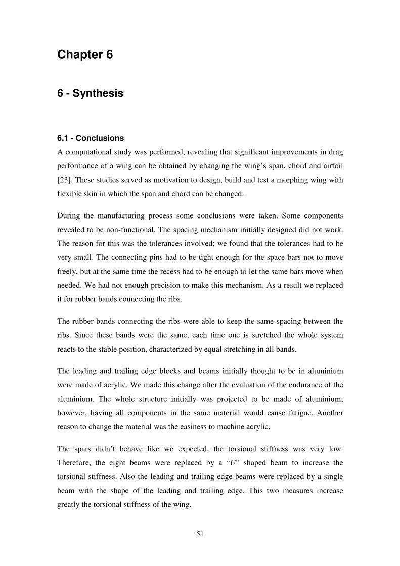
51
Chapter 6
6 - Synthesis
6.1 - Conclusions
A computational study was performed, revealing that significant improvements in drag
performance of a wing can be obtained by changing the wing’s span, chord and airfoil
[23]. These studies served as motivation to design, build and test a morphing wing with
flexible skin in which the span and chord can be changed.
During the manufacturing process some conclusions were taken. Some components
revealed to be non-functional. The spacing mechanism initially designed did not work.
The reason for this was the tolerances involved; we found that the tolerances had to be
very small. The connecting pins had to be tight enough for the space bars not to move
freely, but at the same time the recess had to be enough to let the same bars move when
needed. We had not enough precision to make this mechanism. As a result we replaced
it for rubber bands connecting the ribs.
The rubber bands connecting the ribs were able to keep the same spacing between the
ribs. Since these bands were the same, each time one is stretched the whole system
reacts to the stable position, characterized by equal stretching in all bands.
The leading and trailing edge blocks and beams initially thought to be in aluminium
were made of acrylic. We made this change after the evaluation of the endurance of the
aluminium. The whole structure initially was projected to be made of aluminium;
however, having all components in the same material would cause fatigue. Another
reason to change the material was the easiness to machine acrylic.
The spars didn’t behave like we expected, the torsional stiffness was very low.
Therefore, the eight beams were replaced by a “U” shaped beam to increase the
torsional stiffness. Also the leading and trailing edge beams were replaced by a single
beam with the shape of the leading and trailing edge. This two measures increase
greatly the torsional stiffness of the wing.
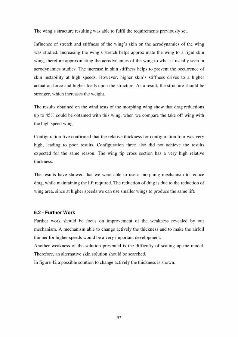
52
The wing’s structure resulting was able to fulfil the requirements previously set.
Influence of stretch and stiffness of the wing’s skin on the aerodynamics of the wing
was studied. Increasing the wing’s stretch helps approximate the wing to a rigid skin
wing, therefore approximating the aerodynamics of the wing to what is usually seen in
aerodynamics studies. The increase in skin stiffness helps to prevent the occurrence of
skin instability at high speeds. However, higher skin’s stiffness drives to a higher
actuation force and higher loads upon the structure. As a result, the structure should be
stronger, which increases the weight.
The results obtained on the wind tests of the morphing wing show that drag reductions
up to 45% could be obtained with this wing, when we compare the take off wing with
the high speed wing.
Configuration five confirmed that the relative thickness for configuration four was very
high, leading to poor results. Configuration three also did not achieve the results
expected for the same reason. The wing tip cross section has a very high relative
thickness.
The results have showed that we were able to use a morphing mechanism to reduce
drag, while maintaining the lift required. The reduction of drag is due to the reduction of
wing area, since at higher speeds we can use smaller wings to produce the same lift.
6.2 - Further Work
Further work should be focus on improvement of the weakness revealed by our
mechanism. A mechanism able to change actively the thickness and to make the airfoil
thinner for higher speeds would be a very important development.
Another weakness of the solution presented is the difficulty of scaling up the model.
Therefore, an alternative skin solution should be searched.
In figure 42 a possible solution to change actively the thickness is shown.
53
Figure 42 - Solution to change actively the thickness
With this kind of solution when the chord is extended or retracted the thickness also
increases or decreases. As a result, the relative thickness may be kept constant.
The solution presented will require a high actuation force due to the skin. The bigger
wing surface leads to a more stretched skin, increasing the tension on it. To overtake
this problem a screen cover with a flat plate solution can be very helpful, since the force
required to actuate this mechanism is not dependent on the wing surface, as it is
sketched in figure 43.
Figure 43 - Solution to decrease to actuation force
The flat plate will give the wing airfoil shape and prevent the turbulence that will be
created by the screen.
54
References
[1] M. Abdulrahim, “Flight Dynamics and Control of an Aircraft with Segmented
Control Surfaces”, University of Florida, AIAA-RSC2-2003-U-010.
[2] M. Abdulrahim and J. Cocquyt, “Development of mission capable flexible wing
micro air vehicles”, University of Florida, Gainesville, FL 32611-6250, 2002.
[3] Anderson, J. D., Corda, S., and Wie, D. M. V., “Numerical Lifting Line Theory Applied to
Drooped Leading-Edge Wings Below and Above Stall,” Journal of Aircraft, Vol. 17, No. 12,
1980, pp. 898-904.
[4] Jae-Sung Bae, T. M. Seigler, D. J. Inman, Virginia Polytechnic Institute and State
University, Blacksburg, VA 24061, USAand In Lee Korea Advanced Institute of
Science and Technology, Daejon 305-701, Korea, “Aerodynamic and Aeroelastic
Considerations of A Variable-Span Morphing Wing”
[5] P. Bourdin, A. Gatto and M. I. Friswell, “The Application of Variable Cant Angle
Winglets for Morphing Aircraft Control”, University of Bristol, AIAA2006-3660, 2006.
[6] V. Brederode, “Fundamentos de Aerodinâmica Incompressível”, Author’s ed., 1997
[7] D. Cadogan, T. Smith, F. Uhelsky and M. MacKusick, “Morphing Inflatable Wing
Development for Compact Package Unmanned Aerial Vehicles”, AIAA2004-1807,
2004.
[8] P. Gamboa, P. Aleixo, J. Vale, F. Lau, A. Suleman, “Design and Testing of a
Morphing Wing for an Experimental UAV”, RTO-MP-AVT-146
[9] L. Gonzalez, “Morphing Wing Using Shape Memory Alloy: A Concept Proposal”,
University of Puerto Rico, 2005.
55
[10] M. T. Kikuta, “Mechanical Properties of Candidate Materials for Morphing
Wings”, University of Virginia, December 2003.
[11] O. L. Majer, “The Application of Smart Actuators in the Development of a Model
Plane Wing”, Union College, June 2006.
[12] J. E. Manzo, “Analysis and design of a hyper elliptical cambered span morphing
aircraft wing”, Cornell University, 2006.
[13] www.matweb.com, March 2007
[14] D. A. Neal III, “Design, Development, and Analysis of a Morphing Aircraft Model
for Wing Tunnel Experimentation”, University of Virginia, April 2006.
[15] S. O’Donnel, “Nanotechnology Trends in Materials and Their Impact on
Aviation”, MITRE Corporation, 2004
[16] polymerfem.com/modules.php?name=Materials_Models&material=8, March 2007
[17] www.roymech.co.uk, March 2007
[18] B. Sanders U.S. Air Force Research Laboratory,Wright–Patterson Air Force Base,
Ohio 45433 F. E. Eastep University of Dayton, Dayton, Ohio 45469 and E. Forster U.S.
Air Force Research Laboratory,Wright–Patterson Air Force Base, Ohio 45433,
“Aerodynamic and Aeroelastic Characteristics of Wings with Conformal Control
Surfaces for Morphing Aircraft”
[19] T. M. Seigler, “Dynamics and Control of Morphing Aircraft”, University of
Virginia, 2005.
[20] J. E. Shigley and C. R Mischke, “Mechanical Engineering Design”, 7th
ed.,
McGraw Hill, 2003.
56
[21] A. Shuetze, “Carbon Nanotubes”, University of Victoria, 2006.
[22] M. D. Stubbs, “Kinematic Design and Analysis of a Morphing Wing”, Virginia
Polytechnic Institute and State University, 2003.
[23] M. Usui, J. D. Jacob and S. W. Smith, University of Kentucky, and Stephen E.
Scarborough and David P. Cadogan ILC Dover “Second Generation
Inflatable/Rigidizable Wings for Low-Density Flight Applications“
[24] J. Vale, F. Lau, and A. Suleman, IDMEC-Instituto Superior Tecnico, Lisbon,
Portugal; and P. Gamboa, Universidade da Beira Interior, Covilha, “Optimization of a
Morphing Wing Based on Coupled Aerodynamic and Structural Constraints”, Portugal
AIAA-2007-1890
Top Related