


Languages
Pages
Legal


Austin FrazerEileen KobalAna Maria MaldonadoMarie Rohrbaugh
Moog Gas EvacuationSystems Design Review

The Team Austin Frazer
Role: Lead Engineer - Analysis Major: Mechanical Engineering
Eileen Kobal Role: Lead Engineer – Mixtures
of Gas Fluids Major: Chemical Engineering
Ana Maria Maldonado Role: Team Manager Major: Industrial Engineering
Marie Rohrbaugh Role: Project Manager Major: Mechanical Engineering
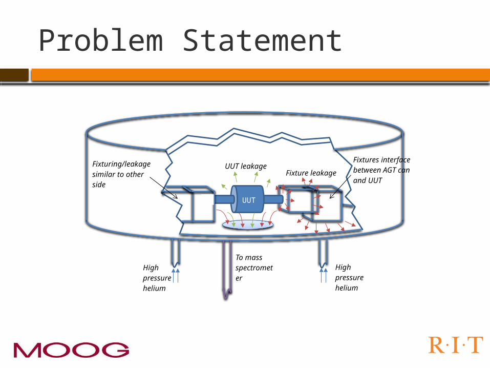
Problem Statement
To mass spectrometer
UUT
High pressure helium
High pressure helium
Fixturing/leakage similar to other side
Fixtures interface between AGT can and UUT
Fixture leakageUUT leakage

Current Procedure
Our process needs to minimize leakage from fixtures
Oring Leakage Diagram
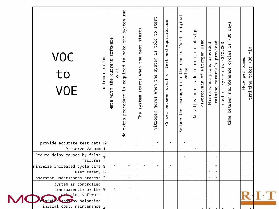
VOC to
VOE customer
rating
Mate with the
current softwar
e system
No extra procedur
e is required to make
the system
run
The system starts when
the test starts
Nitrogen
moves when
the system is
told to start
<5 sec between start of test
and equilibri
um
Reduce the
leakage into the can to 1% of
original value
No adjustment made to
original design
<100scc
/min of
Nitroge
n used
Maintenance plans
provided
Training
materials provided
cost of system is
<$10,000
time betwee
n mainten
ance cycles is
>30 days
FMEA performed
training
takes
<30 min
provide accurate test data 10 * * *
Preserve Vacuum 1 *
Reduce delay caused by false failures 7 * *
minimize increased cycle time 8 * * * * * *
user safety 12 * *
operator understands process 3 * * *
system is controlled transparently by the existing software 9 * *
minimize cost by balancing initial cost, maintenance cost, and consumable
materials6 * * * * * *
sturdy and robust system 11 * *
maximize time between maintenance cycles 4 * *
maintenance plans 5 *
maintenance can be accomplished with minimal money and time 2 * * *
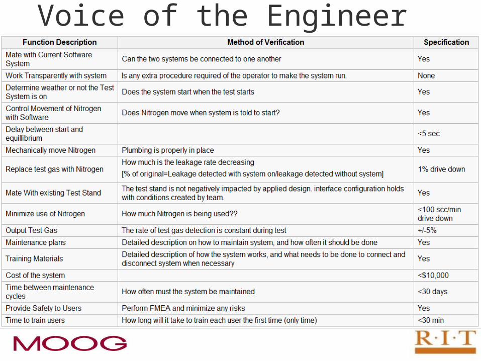
Voice of the Engineer

Design Constraints Safety Contamination
Class 10,000 clean room. All products should comply to a strict cleanliness
certification Existing Fixture
Cannot modify inside of can Must be attachable to can
Gas Flow Nitrogen gas at 120psia available Vacuum at 1psia available

Function Tree
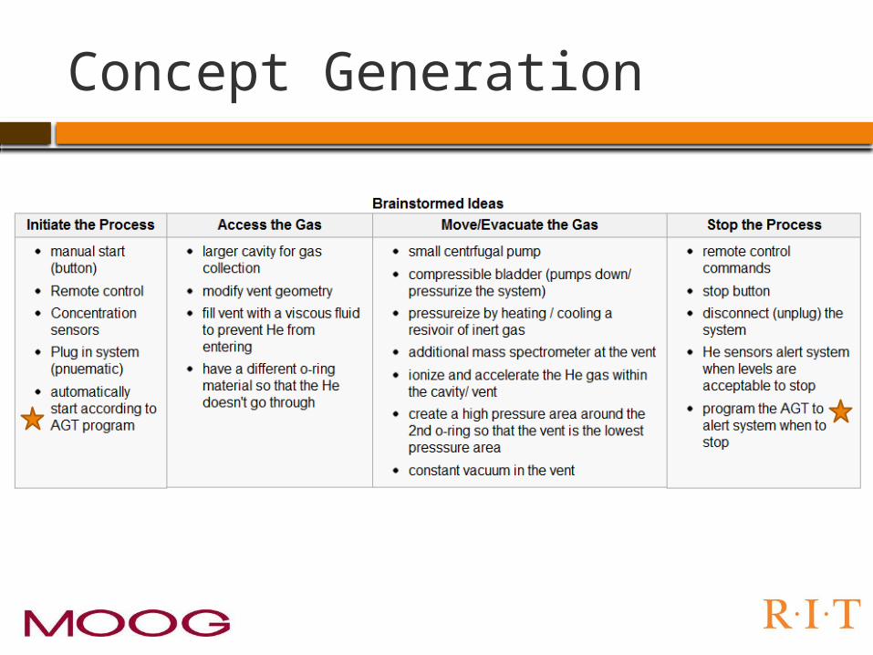
Concept Generation
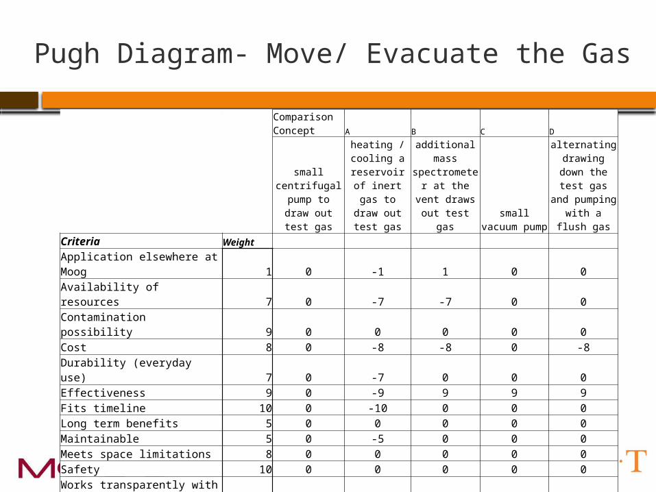
Pugh Diagram- Move/ Evacuate the Gas
Comparison Concept A B C D
small centrifugal pump to draw
out test gas
heating / cooling a
reservoir of inert gas to
draw out test gas
additional mass spectrometer at the vent draws
out test gassmall vacuum
pump
alternating drawing down
the test gas and pumping with a
flush gasCriteria Weight
Application elsewhere at Moog 1 0 -1 1 0 0Availability of resources 7 0 -7 -7 0 0Contamination possibility 9 0 0 0 0 0Cost 8 0 -8 -8 0 -8Durability (everyday use) 7 0 -7 0 0 0Effectiveness 9 0 -9 9 9 9Fits timeline 10 0 -10 0 0 0Long term benefits 5 0 0 0 0 0Maintainable 5 0 -5 0 0 0Meets space limitations 8 0 0 0 0 0Safety 10 0 0 0 0 0Works transparently with current system 9 0 0 -9 0 0 0 -47 -14 9 1

Pugh Diagram- Access the Gas
Comparison
Concept A B C
larger cavity for gas collection
modify vent geometry
fill vent with a viscous fluid to
prevent He from entering
have a different o-ring material so that the He
doesn't go through
Criteria Weight
Application elsewhere at Moog 1 0 0 -1 1
Availability of resources 7 0 0 -7 -7
Contamination possibility 9 0 0 -9 -9
Cost 7 0 -7 7 -7
Durability (everyday use) 7 0 0 -7 0
Effectiveness 9 0 9 -9 0
Fits timeline 10 0 0 0 0
Long term benefits 5 0 0 -5 0
Maintainable 5 0 0 -5 5
Meets space limitations 8 0 0 8 8
Safety 10 0 0 10 0
Works transparently with current system 9 0 0 -9 9
0 2 -27 0

Block Diagram

Flexline to Nitrogen Source
Flexline to Vacuum Source
To vent
To large o-ring X2
Relief Valve
AN Fitting
2-way 2-position solonoid valve

Flexline to Nitrogen Source
Flexline to Vacuum Source
To vent
To large o-ring X2
Relief Valve 3-way 2-
position solonoid valve
AN Fitting
2-way 2-position solonoid valve

Analysis Performed – Simscape Model
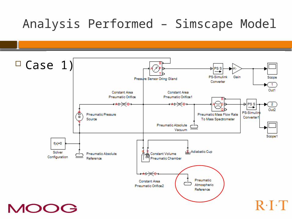
Analysis Performed – Simscape Model
Case 1)
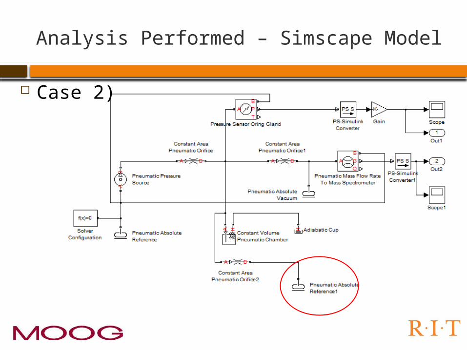
Analysis Performed – Simscape Model
Case 2)

Analysis Performed – Simscape Parameters
Model Orings as Orifices
1 2 𝐾=𝜌
2𝐶𝑑2 𝐴2
𝛿𝑃=𝑃1−𝑃2
L = Approximate leak rate of the seal, std. cc/sec.F = Permeability rate of the gas through the elastomer at the anticipated temperature, std. cc cm/cm2 sec bar. (example: Butyl's permeability at 77oF with Acetylene is 1.26 x 10⁻⁸ std. cc cm/cm2 sec bar)D = Inside diameter of the O-ring, inches.P = Pressure differential across the seal, lb/in2 .Q = Factor depending on the percent compression and whether the O-ring is lubricated or dry (from figure 3 below)S = Percent compression on the O-ring cross section expressed as a decimal (i.e. for 20% compression, S = 0.20)
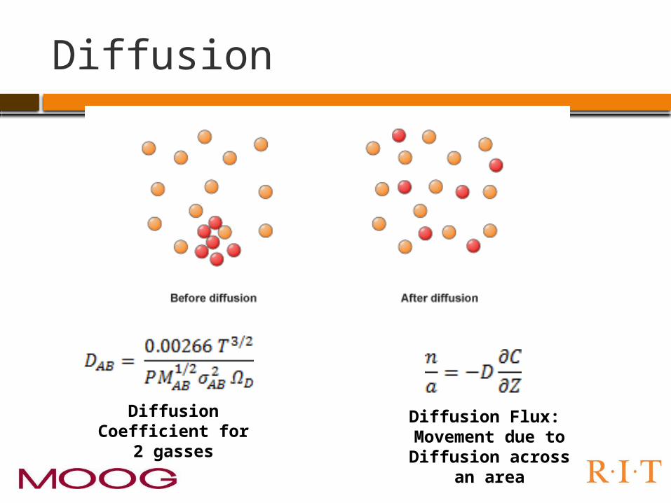
Diffusion
Diffusion Coefficient for 2
gasses
Diffusion Flux: Movement due to
Diffusion across an area
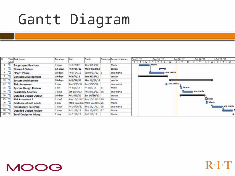
Gantt Diagram

Risk Assessment

Questions??
Top Related