


Languages
Pages
Legal


•Openframe
•Media Player
•Transparent Signage
•Video Wall
MONITOR SIGNAGE MODELS
1 OPENFRAME SIGNAGE
1-1. Keep temperature 0°C ~ 40°C(Mandatory)
1-2. Consider using a cooling & heater solution(Mandatory)
1-3. Do not disassemble Handle, Fan or Side bracket(Mandatory)
1-4. Do not use a screw is longer than 9.0mm(Mandatory)
1-5. Recommend not to place the front panel in direct sunlight
1-6. Use the side bracket to mount into the enclosure
1-7. Refer to brightness of according to ambient luminance
2 MEDIA PLAYER
2-1. Minimum distance between media player and structure(100mm)
2-2. Install Dust filter & keep temperature 0°C ~ 40°C(Mandatory)
3 TRANSPARENT SIGNAGE
3-1. Preparation for Installation
3-2. Portrait mode: Rotate the set clockwise 90°(Mandatory)
3-3. Attach the product using the prepared screw holes(Mandatory)
3-4. How to connect cable assembly
3-5. Refer to ventilation hole of enclosure
3-6. Refer to Lighting set up
3-7. Refer to storage place(AD Board & Media Player)
3-8. Dimension of Screw Holes(26TS30MF/47TS30MF)
3-9. Recommendation: Lighting is 600 LUX or more
4 VIDEO WALL
4-1. Precaution in movement & handling
4-2. Installing the Product
4-3. Tiling Display(How to join Sets)
4-4. Daisy Chain Monitors
4-5. Function Setting(Multivision Configuration)
4-6. Setting the Installation Menu
4-7. Setting the Tile Mode
4-8. Setting the Picture ID
CONTENTS

OPENFRAME SIGNAGE
1-1. Keep temperature 0°C ~ 40°C(Mandatory)
When designing the enclosure, the temperature inside the enclosure must be maintained
between 0°C and 40°C.
The Measurement method for checking the operating temperature inside the enclosure
Enclosure
0’C ~ 40’C
Openframe Signage (eg. 47WX50MF)
5cm
Thermal sensor 5cm
5cm Example
1. Should install a thermal sensor inside the enclosure.
There are three location for thermal sensor.
(backside of the top , backside of the middle,
backside of the bottom)
2. On this basis of you measuring temperature,
Ensuring that you keep the temperature being 0°C ~ 40°C

1-2. Consider using a cooling & heater solution (Mandatory)
To maintain the temperature inside the enclosure, you may consider using a cooling
and heater solution such as an air conditioner, heat exchanger, or combined cooler
and heater depending on the external environment. (Please see below examples)
You can also employ an air flow circulation system and air curtain* between the front
panel and the enclosure.
Example 2 : Enclosure (Heat exchanger) Example 1 : Enclosure (Just fans)
Example 4 : Direct Air Cooling Solution Example 3 : Enclosure (Air conditioner)
Air Curtain Air Curtain
Air Curtain Air Curtain
Heater
Membrane Filter
FAN
Humidity Sensor
Protection
glass
Recommend to design the exterior of the enclosure to meet with the IP65 standard.
Use a dust filter to prevent dust .(At air inlet and outlet )
Filter should be used for filtering out bugs, dust and water.
For preventing from rust of lead frame in circuit board,
operates the Heater if relative humidity is high.
*Air curtain :
Air flow circulation system between
the front panel and the enclosure.

1-3. Do not disassemble Handle, Fan or Side bracket (Mandatory)
Do not disassemble the parts such as Handle, Fan or Side bracket
for preventing of product safety & function problem
Handle
Side bracket
Fan
*47WX50MF

1-4. Do not use a screw is longer than 9.0mm (Mandatory)
You must use the side screw holes when mounting the panel
The Side screw holes are M4.0 Tap , Torque 4~5Kgf.cm, pitch 0.7mm
The Screw hole depth of the panel is:9.0mm (Max)
If a screw is longer than 9.0mm, it may cause damage to the LCD panel
It is advisable to only use spring washer-type screws.
▪Example : Spring washer type
Side Hole
47WX50MF

1-5. Recommend not to place the front panel in direct sunlight
NOTE
• To prevent sunlight, consider to attach a UV film on the glass
• It is recommended not to place the front panel in direct sunlight.
• For Example-Using a canopy may prevent the enclosure temperature increase due to
direct sunlight.
Good Example

1-6. Use the side bracket to mount into the enclosure
1-7. Refer to brightness of according to ambient luminance
• You should use the side bracket to mount the signage display into the enclosure.
•This is measurement of 47WX50MF’s Auto Brightness Control function
Ambient Luminance
(Lx)
Brightness
(nits)
0 410
10 415
25 419
50 421
100 602
200 784
300 1131
400 1850
500 2024
Bri
gh
tness (n
its)
Side Bracket
47WX50MF
Ambient light (Lx)
Auto Brightness Control Curve(47WX50MF)

2-1. Minimum distance between media player and structure
(100mm)
MEDIA PLAYER
• Monitor Back Cover Mount Condition
• Application model : NC1000, NA1000, NA1100, MP500, PC100
• Minimum distance between player & structure : 100mm distance to X,Y,Z axis direction
• 0°C< Ambient temperature <40°C
100mm
100mm 100mm
100mm
Piggy bag type

2-2. Install Dust filter & keep temperature 0°C ~ 40°C (Mandatory)
• Embedded Mount Condition
• Application model : NC1000, NA1000, NA1100, MP500, PC100
• Minimum distance between media player and structure : 100mm distance to X,Y,Z axis direction
•Should install dust filter in ventilation area
• When the unit is operating, you must keep temperature inside being 0°C ~ 40°C
100mm
100mm
100mm
100mm
100mm
Ventilation
Ventila
tion
Ventila
tion
Hot air
Cool air
▪ Dust filter
Enclosure
Media player

3-1. Preparation for Installation
TRANSPARENT SIGNAGE
• Preparation for Installation
• Please refer to the “LVDS Pin Map Guide” in the manual.
Preparation Items
(26TS30MF/47TS30MF)
• Need to purchase separately the below items

3-2. Portrait mode: Rotate the set clockwise 90°(Mandatory)
• Portrait Layout(Only supported for 47TS30MF)
• To install in portrait mode, rotate the set clockwise 90 degrees when looking at the front.
(The AD board should support portrait mode)
3-3. Attach the product using the prepared screw holes (Mandatory)
Landscape
Portrait CAUTION
• The 26TS30MF model don’t support the portrait mode because of module characteristic
• Transparent Signage enclosure construction.

3-4. How to connect cable assembly
Cable assembly

3-5. Refer to ventilation hole of enclosure
3-6. Refer to lighting set up
•Transparent Signage enclosure construction
•Transparent Signage enclosure construction
Front view Side view Back view
Opening the door view
Working display with enclosure Side type lighting Ceiling type lighting
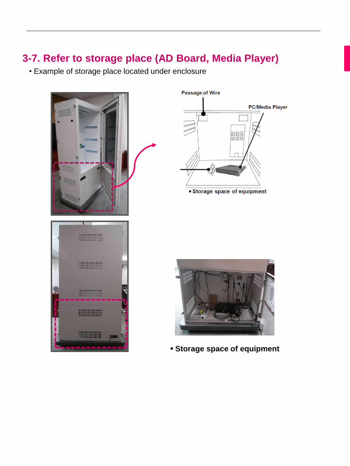
3-7. Refer to storage place (AD Board, Media Player)
• Example of storage place located under enclosure
▪ Storage space of equipment

3-8. Dimension of Screw Holes
Transparent Signage enclosure construction
Dimension of Screw Holes : You should use M3 screws to mount the monitor. There are
16ea(26”),20ea(47”) prepared screw holes on the rear side of the product.
Caution : The length of screw can vary according to thickness of the enclosure guide
frame. So please check this.
[Screw hole of backside for 47TS30MF]
[Screw hole of backside for 26TS30MF]

3-9. Recommendation: Lighting is 600 LUX or more
This product must be installed with lighting.
The Lighting must be installed behind the product so that
the display can be seen clearly.
NOTE The minimum required lighting luminance can vary according to the environmental conditions
and enclosure design.
Example of lighting
Installing a certain object behind the screen may
require additional lighting.
Side type lighting
Ceiling type lighting
600 lux or more
600 lux or more

4-1. Precaution in movement
Video wall
Adhere to the warning signs printed on the Box.
Don’t tumble the Set box sideward down.
Don’t lie on or lean on the Set box.
Precaution
Model:
47WV30MS
47WV30BR
47WV30BS
47WV30-BAAM
47WV30-BAAL

Precaution in Handling
Move the Set as a team of 2 persons.
When you move the bare Set, please use one hand on grabbing the handle
and the other support under the Set.
CAUTION This way up/ Fragile/ Keep away from rain/ Stacking limit 4.

Causes & Phenomena of the Line Defect
The line defect would occur on your Set if you strike on the edge of the Set.
LOG (LINE ON GLASS) DEFECT
Shock on Module Left/Top Corner Left/Top LOG Crack Horizontal Line Defect
LOG (LINE ON GLASS) DEFECT
Shock on Module Top Side Top COF Crack
Vertical Line Defect
Shock on Module Left Side Left COF Crack
Horizontal Line Defect

Do not Collide & Install with enough airflow
Be careful not to collide the sets with the floor or with each other.
Install in the space with enough airflow
Panel
Panel

4-2. Installing the Product
Cut Packing Strap of the Box.
Remove the Upper Box.
Cut Tape on the Box.
Open the Box and remove the top packing.
Open the Poly Bag. Undress the Poly Bag.

Lift up the Set using the SIDE/BACK Handle. Remove Bottom packing when lifting up the Set.
With one hand under the set and the other hand grabbing the set, move the set.
Lay the back of the Set down on the table.

Use the cushion or Pad when you lay the face of the Set downward.
Connect IR receiver to use remocon. And then, connect power code.

Remove L-brackets before Installation
Remove the L-brackets from each corner of the monitor before installing it.
NOTE
Keep the removed L-brackets and use them when moving the monitor later.
CAUTION
When you connect Monitor sets for multivision, you may find that the screen
color is not the same across all the Monitor sets. If you want to adjust
the screen color manually, please refer to the Installation Manual.
When you install multiple Monitor sets onto a wall, attach the IR Receiver
to all the sets, or use an RS-232C cable to connect them and then attach
the IR Receiver to the first set.
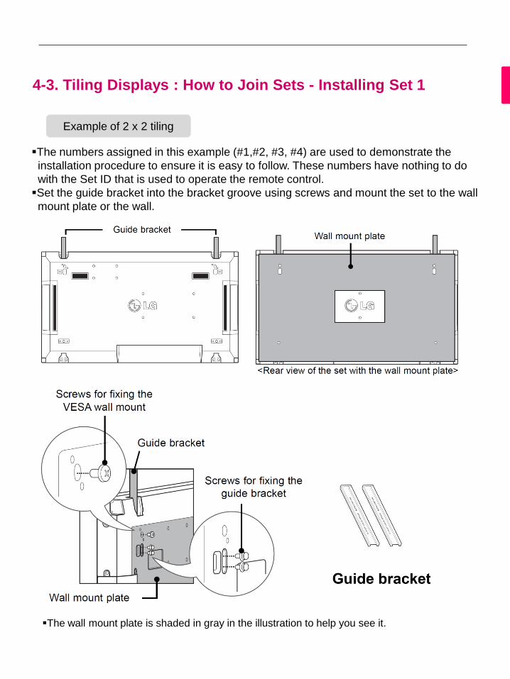
4-3. Tiling Displays : How to Join Sets - Installing Set 1
The numbers assigned in this example (#1,#2, #3, #4) are used to demonstrate the
installation procedure to ensure it is easy to follow. These numbers have nothing to do
with the Set ID that is used to operate the remote control.
Set the guide bracket into the bracket groove using screws and mount the set to the wall
mount plate or the wall.
Example of 2 x 2 tiling
The wall mount plate is shaded in gray in the illustration to help you see it.

4-3. Tiling Displays : How to Join Sets - Installing Set 2
Join Set 2 to Set 1 using the guide brackets on the top side of Set 1 and mount the two
sets to the wall mount plate or the wall.
Remove the guide brackets after mounting the sets.
The sets joined with the guide brackets
<Rear view of the set with the wall mount plate>
The sets after removing the guide brackets

Unscrew the guide bracket screws from the rear of the set and remove the guide brackets.
Once the screws are removed, the guide brackets will drop. You need to remove them
through the gap on the sides of the set.
This can be done only when there is enough space between the set and the wall mount
plate or the wall to unscrew the screws. (Please check whether there is enough space
to remove the screws before fixing the guide brackets.)
Removing the guide bracket through the side gap
How to remove the guide brackets

4-3. Tiling Displays : How to Join Sets - Installing Set 3
Fix the guide brackets to Set 3 following the steps above, and loosely mount the set to
the wall mount plate or the wall.
Minimize the space between the sides of the sets using the U-shaped fixture.
When the sets are firmly mounted to the wall, remove the U-shaped fixtures.

4-3. Tiling Displays : How to Join Sets - Installing Set 4
Loosely mount Set 4 to the wall mount plate or the wall and minimize the space
between the sets using the U-shaped fixtures.
When Set 4 is firmly mounted to the wall, remove the U-shaped fixtures.
Remove the guide brackets. See <How to Join Sets - Installing Set2,3>.
Now the 2 x 2 tiling is complete.
You can tile in various combinations, such as 3 x 3.
Set 4 joined to the rest of the sets
(2 x 2 tiling)
CAUTION
The guide brackets for tiling should only be used to join sets and should be
removed once they are joined.
The guide brackets should only be used as the assisting tool when tiling sets.
The load applied to each set should be supported by the wall mount plate or
the wall using a VESA wall mount (800 x 400).
(Each set must be firmly mounted to the wall mount plate or the wall.)
The guide brackets must be removed once the sets are joined. When joining
the sets without removing the guide brackets, extra caution is required to
prevent damage due to the set weight.
The U-shaped fixtures must also be removed after mounting the set to the
wall mount plate or the wall.

4-4. Daisy Chain Monitors
RGB Cable
15-pin D-Sub Signal Cable (Max 3m)
DVI Cable DVI Cable (Max 3m)
NOTE "Input signal may be degraded or lost when multiple monitors are connected.
For DVI, in general, up to 12 monitors can be connected via the DVI Out port
(at the recommended resolution) if the signal is stable and there is no cable loss.
(If you want to connect more than this number of monitors, we recommended
that you use a distributor.)
When the tile mode is configured via DVI cables, only the monitor that receives
first signals can play HDCP-encrypted content.
(The DVI Out port does not support HDCP).
If the signal cable between the product and your PC is too long, make sure to
use the DVI (RGB) booster or DVI (RGB) optical cable.
If input signals are received through the HDMI/DP cable, multiple monitors
cannot be connected via the DVI Out port"

4-5. Function Setting (Multivision Configuration) 1/2
1. IR Receiver connection. 2. Connecting the Power code
3. Set ID setup for each set.
4. IR Receiver removal for all sets except for Set 1.
5. Signal cable connection.
IR Receiver
Remote
control IN port
(example) 2x2 Set
Set ID:1 Set ID:2
Set ID:3 Set ID:4
Assign the “Set ID” to each Set as below:
1
3
2
4
5

4-5. Function Setting (Multivision Configuration) 2/2
6. Connect the Monitor sets, in series, using an RS-232C cable.
7. Installation Menu setup.
8. Tile Mode setup.
Refer to..
“ Setting the Installation Menu”
Refer to..
“ Setting the “Setting the Tile Mode”
6
7
8

4-6. Setting the Installation Menu (1/2)
If you press the MENU button on the remote control for more than five seconds,
the main menu appears and then disappears. The input data is also displayed in
the upper left corner of the screen.
Press the "0" button four times. Press the OK button.
When the Installation Menu is displayed, select the item you want.
1
2
3

4-6. Setting the Installation Menu (2/2)
Menu Description
Signage Mode
Operation
Decide to work all functions of 'Signage Mode Operation' or not.
15Min Force Off Turns off the monitor if there is no input for more than 15 minutes.
"No" is the recommended default value setting.
4 hours off Turns off the monitor if there is no input on the remote control for
more than four hours."No" is the recommended default value setting.
Wake On LAN Turns on the monitor remotely using LAN.
Total Set ID Sets the maximum value for picture IDs.
DPM Enters energy saving mode if there is no input signal.
Software Update Sets whether to use NSU (Network Software Update).
Power On Status Decide to select working status of Monitor Set when turn on main
power.
Input Source
Change
Decide to change input source or not by setting 'Input Source
Change' as Yes(Change possible) or No(Change impossible).
Menu Display MENU key does not work if 'Menu Display' is set to No.
OSD Display Decide to display OSD or not by setting 'OSD Display' as Yes(Mark)
or No(No Mark).
Min Volume Decide 'Min Volume' between changing range 0 to 100.
Max Volume Decide 'Max Volume' between changing range 0 to 100.
Power On
Default
With the power turned on, you can set the 'Input Source' and
'Volume’ options.
Input Source Set whether it is turned on by the set input source or by the last
stored input source.
Volume This sets whether to apply the Volume Level or not when the power
is turned on.
Aspect Ratio With the power turned on, you can set the 'Aspect Ratio' option with
the pre-defined value.
Intelligent Auto If the setting is Yes, Display is automatically arranged through
resolution size when you change the resolution at the first.
Factory Reset If it is set to No, 'Factory Reset' under OPTION is disabled.

4-7. Setting the Tile Mode
In Tile Mode you can view an image in a larger scale by connecting multiple monitors.
Tile Mode Off: An input image is not enlarged, and the same image is shown on
all connected monitors.
Tile Mode On: An input image is enlarged according to the value in the H. Set Count
and V. Set Count fields.
When using 9 monitors
Example: 2 x 2 Example: 3 x 3
Tile ID

4-8. Setting the Picture ID (1/2)
Picture ID is used to change the settings of a specific set (display) using a single IR
receiver for multi-vision. The set receiving the IR signal communicates with another
set via the RS232 connector. Each set is identified by a Set ID. If you assign the
Picture ID using the remote control, only displays with the same Picture ID and Set ID
can be controlled remotely.
2X2 Multi-Vision (Total Set ID: 4)
Set IDs are assigned as shown in the picture.

4-8. Setting the Picture ID (2/2)
1. Press the ID On (Red) button
on the remote control.
2 If you press the left/right buttons or press
the ON button repeatedly, the Picture ID
cycles through OFF and 1 to 4.Assign the
ID you want.
If you assign the Set ID to each set with multi-vision, and then assign the Picture ID
using the red button on the remote control, the key command is displayed for the set
with the same Set ID and Picture ID. A set with different Set IDs and Picture IDs
cannot be controlled by IR signals.
Refer to the Set ID on page 46 for assigning a Set ID.
The maximum value of the Picture ID can be set in the Total Set ID menu.
Please refer to the Installation Manual for more information on the assignment of
a Total Set ID.
NOTE For example, if the Picture ID is assigned to 2, the upper right display (Set ID: 2) can
be controlled by IR signals.
For each set, you can change the settings for the PICTURE, AUDIO, TIME, OPTION,
NETWORK and MY MEDIA menus or the hot keys on the remote control.
If you press the ID OFF (Green) button, the Picture IDs for all sets are turned off.
If you then press any button on the remote control, all sets will start working again.
The Picture ID function may not work during MY MEDIA operating.
1 2
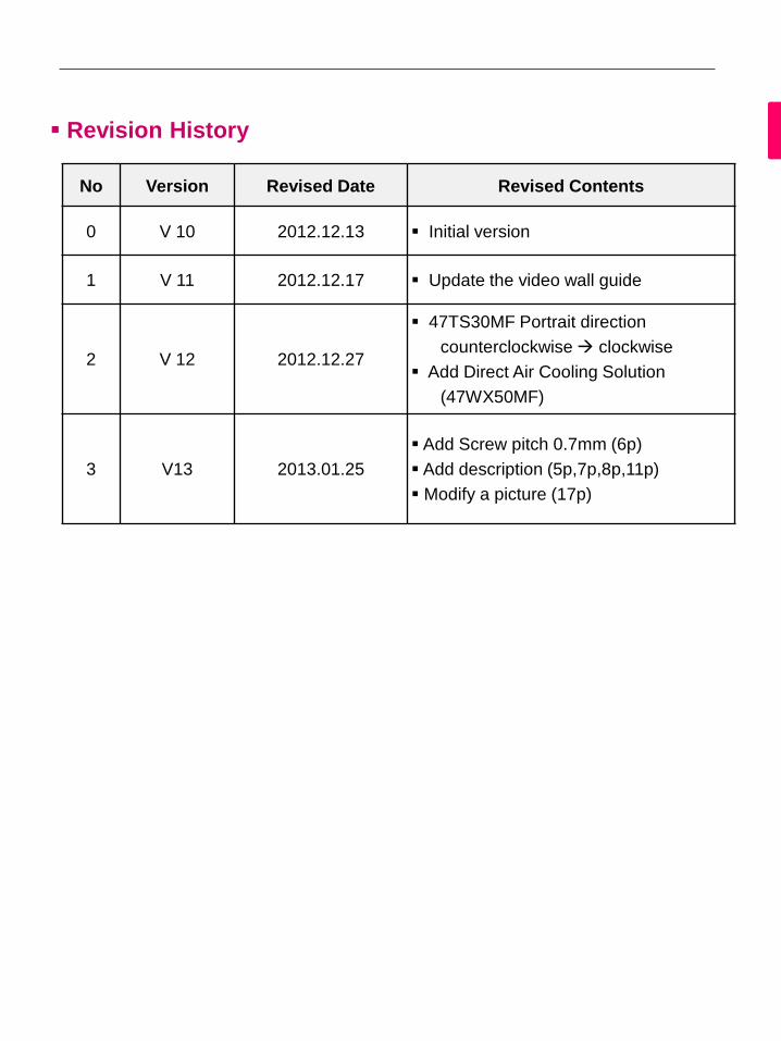
No Version Revised Date Revised Contents
0 V 10 2012.12.13 Initial version
1 V 11 2012.12.17 Update the video wall guide
2 V 12 2012.12.27
47TS30MF Portrait direction
counterclockwise clockwise
Add Direct Air Cooling Solution
(47WX50MF)
3 V13 2013.01.25
Add Screw pitch 0.7mm (6p)
Add description (5p,7p,8p,11p)
Modify a picture (17p)
Revision History

Top Related