


Languages
Pages
Legal


Modeling of Cyclic Load-Deformation Behavior of Shallow Foundations Supporting Rocking Shear Walls
Sivapalan Gajan
Advisor: Bruce Kutter
Seminar – 06. 01. 2005
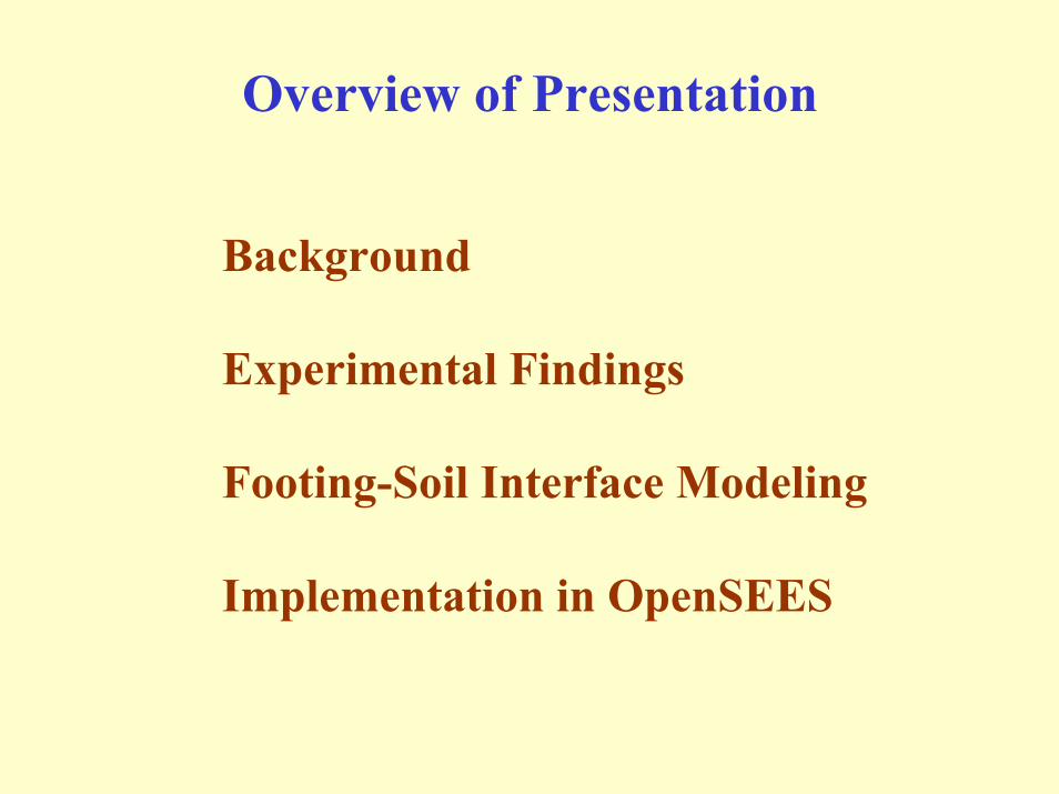
Overview of Presentation
Background
Experimental Findings
Footing-Soil Interface Modeling
Implementation in OpenSEES

Shallow Foundations Supporting Rocking Shear Walls
Material and geometrical nonlinearities – soil yielding and footing uplift
Nonlinear bearing pressure distribution – Nonlinear moment-rotation behavior
Energy dissipation beneath the footing and associated permanent deformations
Shear wall and frame structure (after ATC, 1997)

Soil-Foundation-Structure Interaction
∆, small
Stiff and Strong Foundation
High forcescause shearwall damage ∆, large
Flexible and Weak Foundation
Foundationyielding androcking protectsshear wall
Largedisplacementscause frame
damage
Small displacementsprotect framefrom damage
∆, small∆, small
Stiff and Strong Foundation
High forcescause shearwall damage
High forcescause shearwall damage ∆, large∆, large
Flexible and Weak Foundation
Foundationyielding androcking protectsshear wall
Largedisplacementscause frame
damage
Largedisplacementscause frame
damage
Small displacementsprotect framefrom damage
(ATC 40 – 1997)

Foundation rocking and mobilization of ultimate capacity reduce seismic demands on the structure (FEMA 1997 and ATC 1997)
Issues
•Analytical challenges to reliable modeling of soil-foundation behavior
•Uncertainty in soil properties
•Lack of interaction between Structural and Geotechnical Engineers/Researchers

Purposes of Research
•To further the understanding of footing-soil interface behavior under realistic confining pressures.
•To investigate the effects of static vertical factor of safety (FSV) on energy dissipation and permanent deformations
•To model the nonlinear cyclic load-displacement behavior of footing-soil interface for combined vertical, shear and moment loading - allowing soil yielding and footing uplift.

What Have We Done?
Centrifuge Experiments Macro-Element ModelingUnderstanding Footing-Soil Interface Behavior
Modeling Footing-Soil Interface Behavior
Outcome
Interface Model inOpenSEES

Centrifuge Experiments
Rosebrook (KRR01, KRR02, KRR03)Gajan and Phalen (SSG02, SSG03)Gajan and Thomas (SSG04)Thomas and Gajan (JMT01, JMT02)
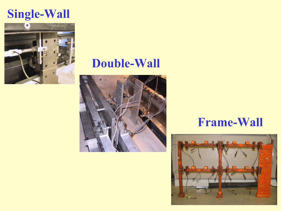
Single-Wall
Double-Wall
Frame-Wall
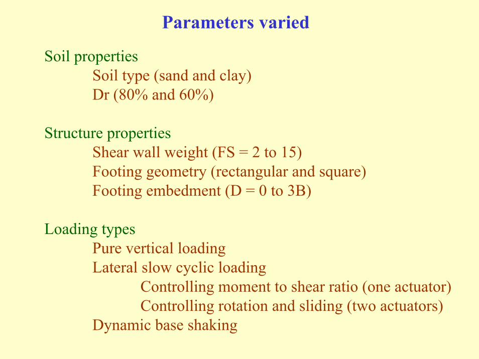
Parameters varied
Soil propertiesSoil type (sand and clay)Dr (80% and 60%)
Structure propertiesShear wall weight (FS = 2 to 15)Footing geometry (rectangular and square)Footing embedment (D = 0 to 3B)
Loading typesPure vertical loadingLateral slow cyclic loading
Controlling moment to shear ratio (one actuator)Controlling rotation and sliding (two actuators)
Dynamic base shaking

Forces and Displacements at the Interface

Load-Displacement Behavior at Interface
FS = 5.0, D = 0.0 m, L = 2.8 m, h = 4.9 m

Effect of Soil Type - Clay
FS = 3.0, D = 0.0 m, L = 2.7 m, h = 4.6 m

Load Paths in V-H-M Space
M
V
M
H
Vertical Load Ratio Moment-to-Shear Ratio
VVFS MAX
V = hHM
=
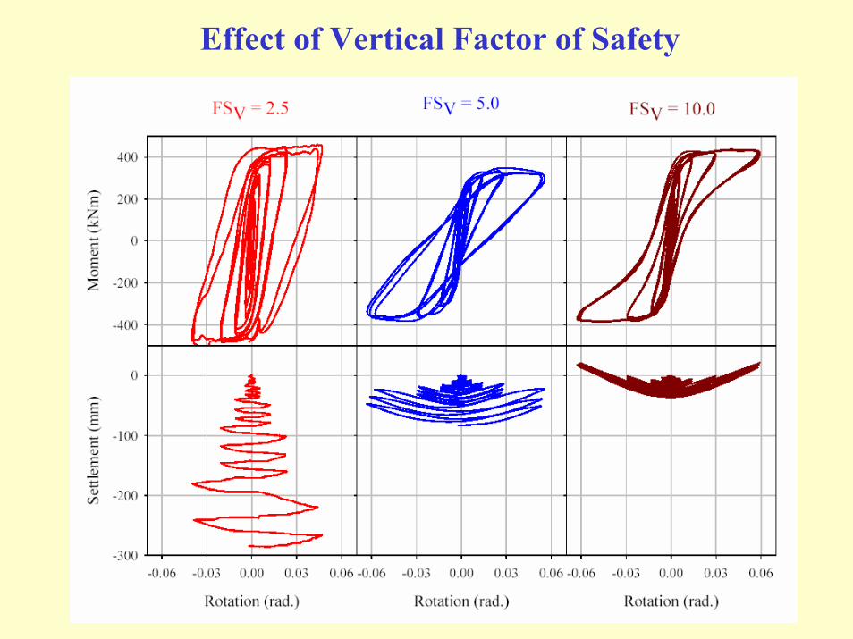
Effect of Vertical Factor of Safety

Effect of Vertical Factor of Safety
same Vult, different V same V, different Vult

Effect of Load Height (M/H = 1.2 m)
FS = 5.0, D = 0.0 m, L = 2.8 m, h = 1.2 m

Dynamic Base Shaking
FS = 5.0, D = 0.0 m, L = 2.8 m, a_max = 0.5 g

Energy Dissipation Vs Permanent Deformation
Half Amplitude Cyclic Rotation (Rad.)
0.001 0.01 0.1
Settl
emen
t per
Cyc
le (m
m)
0
10
20
30
40
FS = 2 ~ 4FS = 5 ~ 8FS = 10 ~ 15
Ener
gy D
issi
patio
n pe
r Cyc
le (k
Nm
)
0
10
20
30
40
A
M
θ
θ
s

Energy Dissipation Vs Permanent Deformation
Half Amplitude Cyclic Rotation (Rad.)
0.001 0.01 0.1
Nor
mal
ized
Set
tlem
ent
0.000
0.005
0.010
0.015
Ener
gy D
issi
patio
n R
atio
0.1
0.2
0.3
0.4
0.5
0.6
FS = 2 ~ 4FS = 5 ~ 8FS = 10 ~ 15
M
θ
A1
A2
EDR = A2 / A1
Uv = s / L

Failure Envelopes in V-H-M Space
Nor
mal
ized
Mom
ent [
F M =
M/(V
ULT
.L)]
-0.15
-0.10
-0.05
0.00
0.05
0.10
0.15
Normalized Vertical Load [FV = V/VULT]
0.0 0.1 0.2 0.3 0.4 0.5 0.6 0.7 0.8 0.9 1.0
Nor
mal
ized
She
ar [F
H =
H/V
ULT
]
-0.15
-0.10
-0.05
0.00
0.05
0.10
0.15
FM/FH = 1.75
FM/FH = 0.42
FM/FH = 1.25
FM/FH = 1.75
FM/FH = 1.25
FM/FH = 0.42Cremer et al. (2001)
Houlsby and Cassidy (2002)
Nova and Montrasio (1991)

Footing-Soil Interface ModelingConsiders foundation and surrounding soil as a single
macro-elementConstitutive model that relates the forces (V, H, M) and
displacements (s, u, θ) acting at the base center point of the footing
macro-element

Lateral Cyclic Loading - Animation
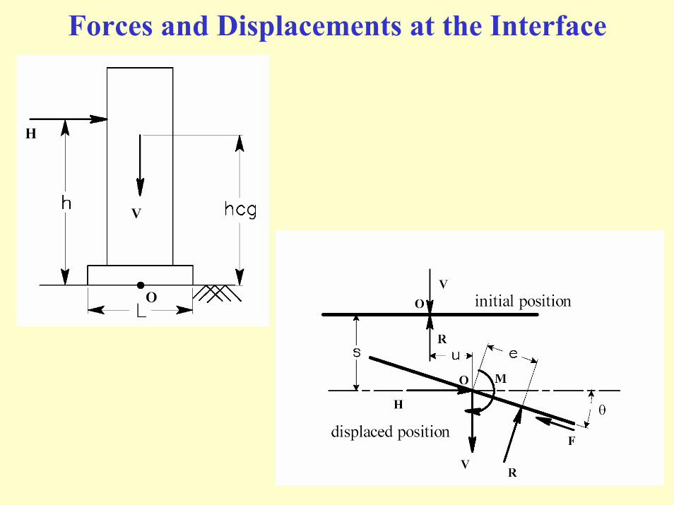
Forces and Displacements at the Interface

Modeling of Moment-Rotation Behavior
Footing locationCurrent soil surface location (soil_min)Maximum past settlement (soil_max)Current bearing pressureMaximum past pressure experienced
Internal variables
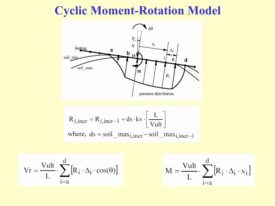
Cyclic Moment-Rotation Model

Model Simulations - Animation

Shear–Sliding Modeling: Coupling with V
1
0
p[i]
i_nodeFS1
qult]i[q]i[p
==
10 p[i]Vult
VFS1Fv ==
VultHFh = [ ]Fv1Fv
21Fh −⋅⋅=

Effect of Moment-to-Shear Ratio on Ultimate Capacities
Normalized Shear [H/VULT]
-0.20 -0.15 -0.10 -0.05 0.00 0.05 0.10 0.15 0.20
Nor
mal
ized
Mom
ent [
M/(V
ULT
.L)]
-0.15
-0.10
-0.05
0.00
0.05
0.10
0.15h/L = 1.75 h/L = 1.25
h/L = 0.42
15
5
FSV = 2
10
FM/FH = h/L
FSV = 2 ~ 5
FSV = 5 ~ 10
FSV = 10 ~ 15
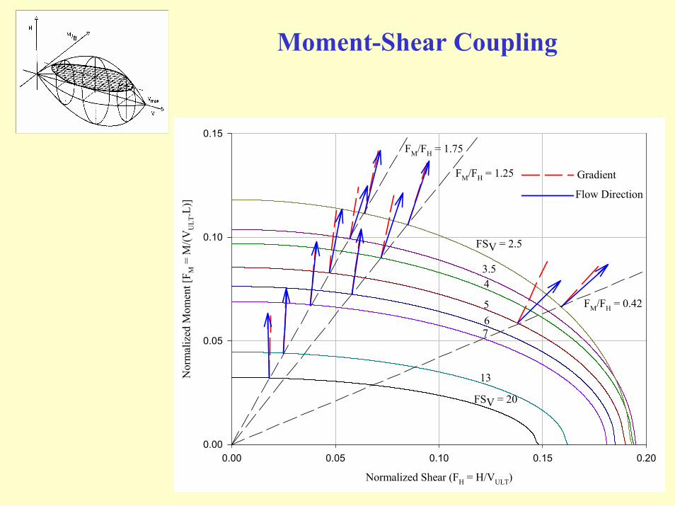
Moment-Shear Coupling
Normalized Shear (FH = H/VULT)
0.00 0.05 0.10 0.15 0.20
Nor
mal
ized
Mom
ent [
F M =
M/(V
ULT
.L)]
0.00
0.05
0.10
0.15
FSV = 20
FSV = 2.5
13
765
43.5
FM/FH = 1.75
FM/FH = 1.25
FM/FH = 0.42
Gradient
Flow Direction

Shear-Sliding Modeling: Global Coupling with M
−
=din_d
dglobal_f
When (d d_in)f_global infinite
When (d 0)f_global 0
2
2
2
2
AB
Lh
AB
FhFm
dud
⋅=⋅=θ
1BFh
AFm
2
2
2
2=+
LVultMFm⋅
=
VultHFh =
du
dθ
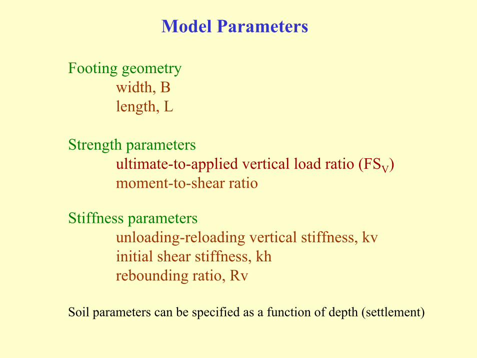
Model Parameters
Footing geometrywidth, Blength, L
Strength parametersultimate-to-applied vertical load ratio (FSV)moment-to-shear ratio
Stiffness parametersunloading-reloading vertical stiffness, kvinitial shear stiffness, khrebounding ratio, Rv
Soil parameters can be specified as a function of depth (settlement)
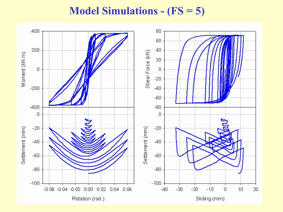
Model Simulations - (FS = 5)

Simulation and Experiment (FS = 5)

Model Simulations - (FS = 2.5)

Simulation and Experiment (FS = 2.5)

Model Simulations - (FS = 7.5)
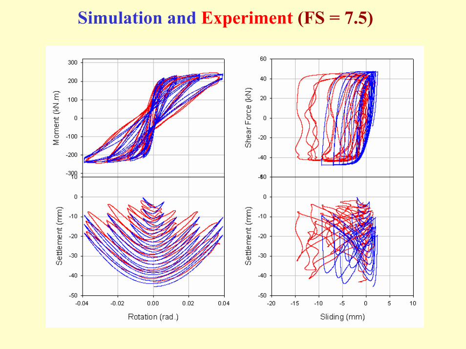
Simulation and Experiment (FS = 7.5)
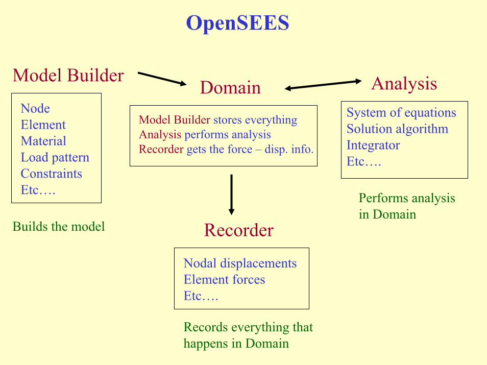
OpenSEES
NodeElementMaterialLoad patternConstraintsEtc….
Nodal displacementsElement forcesEtc….
System of equationsSolution algorithmIntegratorEtc….
Recorder
AnalysisDomain
Builds the model
Performs analysisin Domain
Model Builder stores everythingAnalysis performs analysisRecorder gets the force – disp. info.
Model Builder
Records everything thathappens in Domain
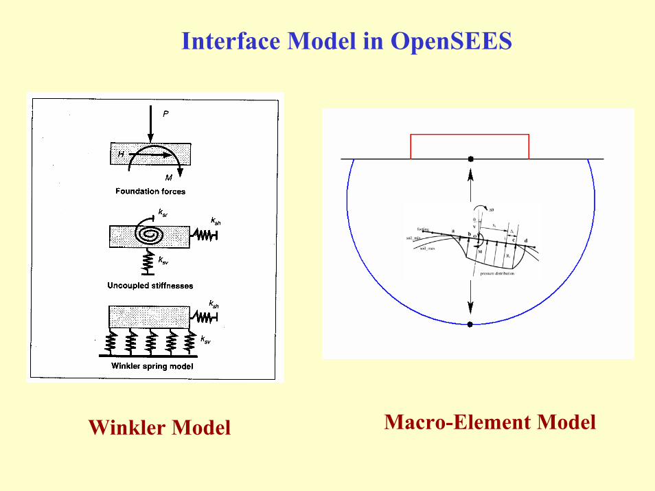
Interface Model in OpenSEES
Macro-Element ModelWinkler Model

Class Hierarchy in OpenSEES
OpenSEES
DomainComponent Material Analysis Classes
Node Element LoadUniaxial Section
SectionForceDeformationFiberSection
Integrator
BeamColumn
ZeroLengthSection
8-node Brick
ConvergenceTest
SoilFootingSection

Accessing the model in OpenSEES
Element - ZeroLengthSection
Section - SoilFootingSection
-ndm 2 –ndf 3
Node i (0, 0)
Node j (0, 0)
Fixed
Free
section SoilFootingSection -secID -Vult -V -L -Kv -Kh <-noSubNodes -tol>
element ZeroLengthSection -eleID -iNode -jNode -secID <-orientation>
i
j
Vult – Ultimate vertical loadV – Self weight of the structureL – Length of the footingKv – Initial vertical stiffnessKh – Initial horizontal stiffness
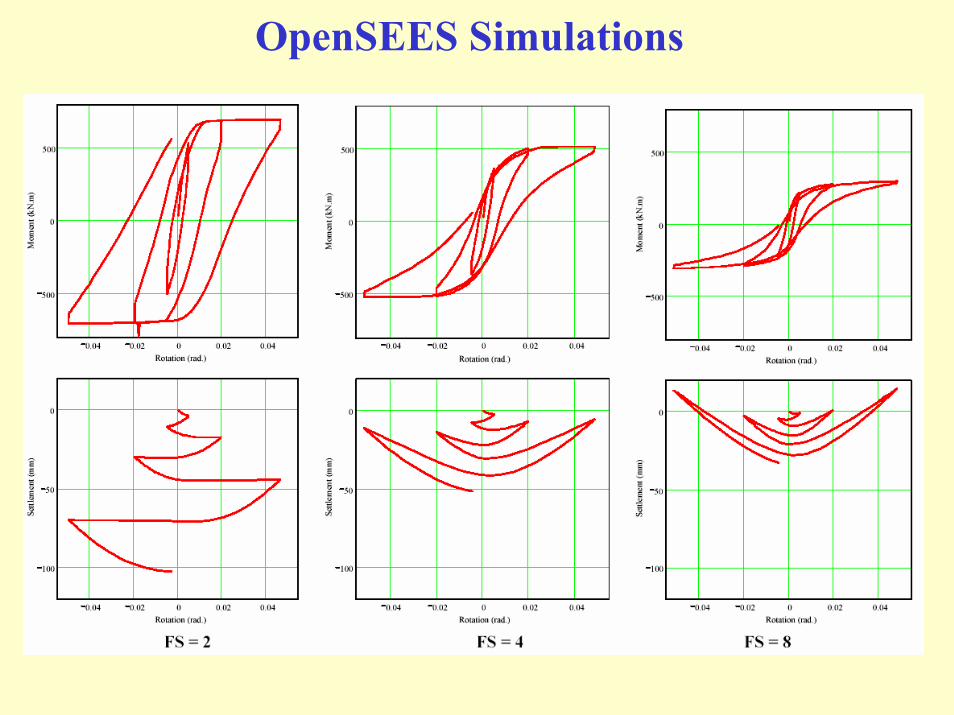
OpenSEES Simulations

Frame – Shear Wall – Foundation System
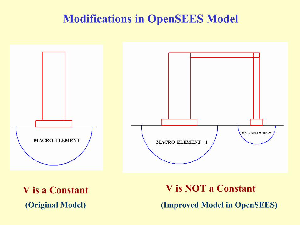
Modifications in OpenSEES Model
V is NOT a ConstantV is a Constant(Original Model) (Improved Model in OpenSEES)
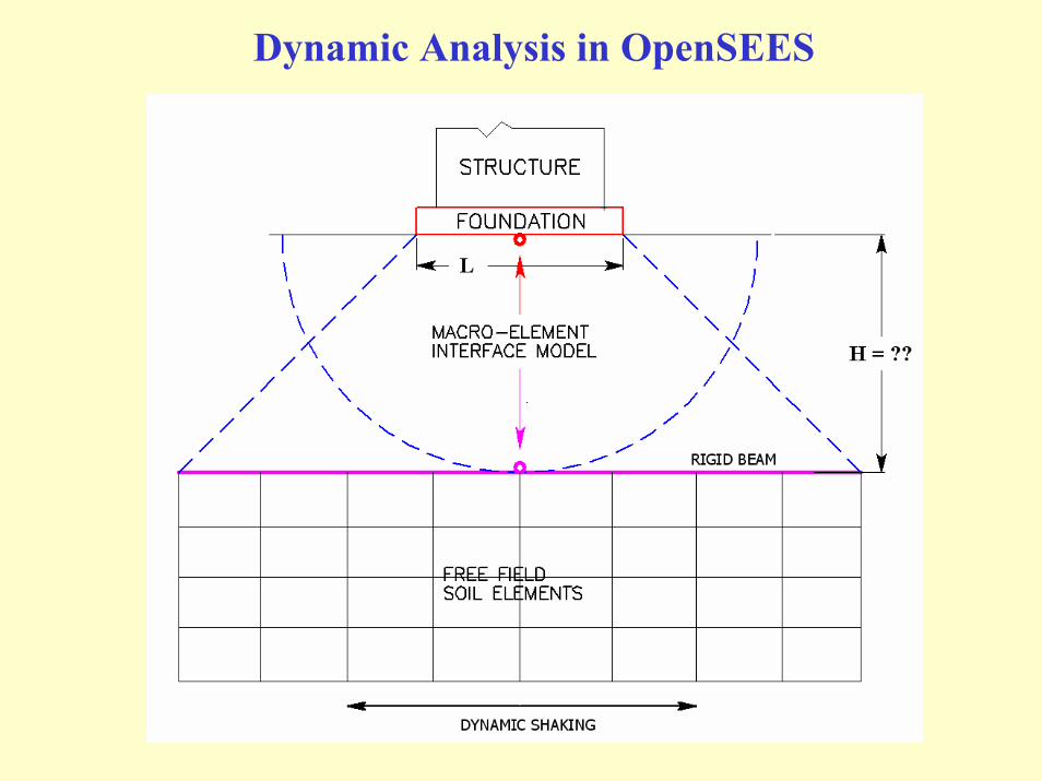
Dynamic Analysis in OpenSEES

Summary
Footing-soil interface behavior depends onStatic vertical factor of safety (FSV)Applied moment-to-shear ratio
Larger FSVIncreases the moment capacity Decreases the permanent deformation
Larger FSV + Rocking allowedConsiderable amount of energy can still be
dissipated without degradation in moment capacity

Footing-Soil “Interface-Element”
Model is based on the physics, geometry and mechanism of the problem and reproduces the load-displacement behavior observed in the experiments
Captures the coupled force-displacement relationships in (V-H-M) space with only 4 major model parameters
No need for external mesh generation and the model is computationally fast
Can be used independently as well as with other structural models to analyse soil-foundation-structure interaction problems
Further Work
Dynamic finite element analysis in OpenSEES with structural, soil and interface elements
Uncertainty analysis – Effect of uncertainties in soil properties on model predictions
Model simulations for I-shape foundations ?
Make the model work better !
Top Related