


Languages
Pages
Legal

Model-based Design, Simulation and Automatic Code Generation
For Embedded Systems and Robotic Applications
by
Ramtin Raji Kermani
A Thesis Presented in Partial Fulfillment of the Requirements for the Degree
Master of Science
Approved September 2013 by the Graduate Supervisory Committee:
Georgios Fainekos, Chair
Yann-Hang Lee Hessam Sarjoughian
ARIZONA STATE UNIVERSITY
December 2013

i
ABSTRACT
As the complexity of robotic systems and applications grows rapidly,
development of high-performance, easy to use, and fully integrated development
environments for those systems is inevitable. Model-Based Design (MBD) [1] of dynamic
systems using engineering software such as Simulink® [2] from MathWorks®, SciCos [3]
from Metalau team and SystemModeler® [4] from Wolfram® is quite popular nowadays.
They provide tools for modeling, simulation, verification and in some cases automatic
code generation for desktop applications, embedded systems and robots. For real-world
implementation of models on the actual hardware, those models should be converted
into compilable machine code either manually or automatically. Due to the complexity of
robotic systems, manual code translation from model to code is not a feasible optimal
solution so we need to move towards automated code generation for such systems.
MathWorks® offers code generation facilities called Coder® products for this purpose.
However in order to fully exploit the power of model-based design and code generation
tools for robotic applications, we need to enhance those software systems by adding and
modifying toolboxes, files and other artifacts as well as developing guidelines and
procedures. In this thesis, an effort has been made to propose a guideline as well as a
Simulink® library, StateFlow® interface API and a C/C++ interface API to complete this
toolchain for NAO humanoid robots. Thus the model of the hierarchical control
architecture can be easily and properly converted to code and built for implementation.
ii
DEDICATION
To:
My beloved parents, Irandokht and Fazlollah
My great brothers, Reza, Ramin, Armin
My wonderful sister, Shideh
My awesome nephew, Mahrad
My best friend, Behrouz
iii
ACKNOWLEDGMENTS
I would like to express my sincere gratitude towards my advisor and committee
chair, Professor Georgios Fainekos for giving me the chance to be a part of his research
team for more than two years and for providing me with invaluable guidelines, great
ideas and feedback, constructive supervision and infinite support as well as providing
state-of-the-art research resources. I would also like to thank Professor Yann-Hang Lee
and Professor Hessam Sarjoughian for their helpful feedback and comments on my work
and being in my defense committee.
I would also like to thank my friends and colleagues in
Cyber Physical Systems lab with whom I had a great experience and from whom I
learned a lot. I would particularly like to thank Kangjin Kim, Bardh Hoxha, Shashank
Srinivas, Shih-Kai Su, Housam Abbas, Adel Dokhanchi, Parth Pandya, Hengyi Yang and
Wei Wei.
I would like to thank all my friends at Arizona State University especially
Mojtaba Rahmati, Afsaneh Nasseri, Mikal Askarian, Pegah Shekh Olia, Mahmoud
Vahidi, Soroosh Gholami, Ronak Valamanesh, Sina Ghods, Shahrzad Shirazipour, Maral
Tabrizi, Nasim Karizi, Sheida Badvipour, Faraz Ebneali, Ali Azarnoush and Shahrouz
Sharifi being with whom I always felt like being at home with a new great family.
This work was partially supported by a grant from the NSF Industry/University
Cooperative Research Center (I/UCRC) on Embedded Systems at Arizona State
University and awards NSF CNS-1116136 and NSF CNS-1017074.
iv
TABLE OF CONTENTS
Page
LIST OF TABLES ............................................................................................................... ix
LIST OF FIGURES ...............................................................................................................x
1 INTRODUCTION ......................................................................................................... 1
1.1 ROBOTIC APPLICATIONS DEVELOPMENT .................................................................... 3
1.2 CYBER PHYSICAL SYSTEM.......................................................................................... 4
1.3 REAL-TIME SYSTEMS ................................................................................................ 4
1.4 MODEL-BASED DESIGN ............................................................................................ 5
1.4.1 Model-based design workflow ........................................................................ 5
1.5 SIMULATION OF PHYSICAL SYSTEMS .......................................................................... 6
1.6 AUTOMATED CODE GENERATION ................................................................................7
1.6.1 What do we mean by Automatic Code Generation? ........................................7
1.6.2 Why are we interested in automatic code generation? ....................................7
1.6.3 Code generation tools ..................................................................................... 9
1.6.4 Steps in code generation ................................................................................. 9
2 RELATED WORK ......................................................................................................10
3 PROBLEM STATEMENT .......................................................................................... 13
3.1 SUMMARY OF THESIS CONTRIBUTIONS ..................................................................... 14
3.2 PROBLEM FORMULATION ......................................................................................... 16
3.2.1 Simulink modeling and code generation ....................................................... 17
3.2.2 StateFlow modeling and code generation ...................................................... 17
3.3 IMPLEMENTATION OBJECTIVES ............................................................................... 20

v
CHAPTER Page
4 BACKGROUND MATERIAL .................................................................................... 23
4.1 AN INTRODUCTION TO MODEL-BASED DESIGN ........................................................ 23
4.1.1 Model based design....................................................................................... 23
4.1.2 Model-based design of cyber physical systems ............................................ 23
4.1.3 Available platforms ....................................................................................... 24
4.2 NAO ROBOTS ......................................................................................................... 26
4.2.1 NAO hardware .............................................................................................. 26
4.2.2 NAO Internals and Operating System .......................................................... 27
4.2.3 Programming NAO ....................................................................................... 28
4.2.4 Choregraphe® and Monitor® ........................................................................ 29
4.2.5 qiBuild system............................................................................................... 32
4.2.6 NAOqi SDK ................................................................................................... 33
4.2.7 Implementing simple behaviors using NAOqi Matlab® API ........................ 37
4.3 MATHWORKS® SOFTWARE ..................................................................................... 40
4.3.1 Simulink® and StateFlow® ........................................................................... 40
4.3.2 Understanding Simulink® simulation ........................................................... 41
4.3.3 Signals in simulation and mapping to the generated code ........................... 44
4.3.4 MathWorks® Coder® products ..................................................................... 48
4.3.5 Matlab® Executables (MEX-Files)................................................................ 50
4.3.6 Simulink Coder® and Embedded Coder® ..................................................... 50
4.3.7 Using PackNGo utility .................................................................................. 55
5 THE PROPOSED SOLUTION .................................................................................. 56
5.1 IDEAL SOLUTION: THE BIG PICTURE ......................................................................... 56

vi
CHAPTER Page
5.1.1 Ideal procedure ............................................................................................. 58
5.2 DESIGN CONSIDERATION .......................................................................................... 61
5.2.1 High level ....................................................................................................... 61
5.2.2 Encapsulation ................................................................................................ 61
5.2.3 Layered Architecture ..................................................................................... 61
5.2.4 Reusable ......................................................................................................... 61
5.2.5 Flexible .......................................................................................................... 62
5.2.6 Expandable ................................................................................................... 62
5.2.7 Hierarchical design ....................................................................................... 62
5.2.8 Debuggable and verifiable ............................................................................ 63
5.2.9 Interface Consistency .................................................................................... 63
5.2.10 Simulink/StateFlow support for proposed design consideration ................ 63
5.3 ARCHITECTURAL DESIGN ........................................................................................ 65
5.3.1 Framework Architecture ............................................................................... 67
5.3.2 NAO Simulink® Library ................................................................................. 71
5.3.3 Target Language Compiler (TLC) files .......................................................... 71
5.3.4 Interface Wrapper Classes and Functions ..................................................... 71
5.3.5 Default configuration file .............................................................................. 72
5.4 FRAMEWORK IMPLEMENTATION ............................................................................. 73
5.4.1 NAO StateFlow Interface API for simulation ............................................... 73
5.4.2 StateFlow® Code generation ......................................................................... 80
5.4.3 C/C++ Interface API for code generation ..................................................... 82
5.4.4 Simulink® model Simulation ........................................................................ 85
5.4.5 Simulink model-based code generation ....................................................... 88
vii
CHAPTER Page
5.4.6 Simulation using Webots ............................................................................... 91
6 EXAMPLES ............................................................................................................... 92
7 CONCLUSIONS AND FUTURE WORK ................................................................... 95
8 REFERENCE GUIDE................................................................................................ 96
8.1 NAO MATLAB API INSTALLATION ........................................................................... 96
8.1.1 NAO Matlab API troubleshooting................................................................. 97
8.2 QIBUILD AND SDK INSTALLATION .......................................................................... 99
8.2.1 qiBuild Installation ....................................................................................... 99
8.2.2 Creating a initializing a Work tree .............................................................. 100
8.2.3 Creating a toolchain ..................................................................................... 101
8.2.4 Status of available toolchains ...................................................................... 101
8.2.5 Creating, configuring and building a new project ....................................... 101
8.2.6 Using Microsoft Visual Studio to build the projects ................................... 104
8.3 CONNECTING TO OPENNAO THROUGH SSH.......................................................... 106
8.4 COMPILING AND BUILDING GENERATED CODE FOR THE MODEL CONTAINING
STATEFLOW CHART IN VISUAL STUDIO ........................................................................... 107
8.4.1 Procedure for generating code from a Simulink model for NAO ............... 109
8.4.2 Using model’s generated code in qiBuild project ........................................ 112
8.4.3 Compilation and run .................................................................................... 114
9 REFERENCES ......................................................................................................... 115
10 APPENDIX A ........................................................................................................... 121
11 APPENDIX B ........................................................................................................... 124
viii
CHAPTER Page
12 APPENDIX C ........................................................................................................... 129
13 APPENDIX D ........................................................................................................... 131
14 APPENDIX E ........................................................................................................... 135
15 APPENDIX F............................................................................................................ 137

ix
LIST OF TABLES
Table Page
1 NAO H25 technical specification ................................................................................. 26
2 Example NAO API classes and associated methods .................................................... 34
x
LIST OF FIGURES
Figure Page
1) Our goal; The big picture ............................................................................................... 2
2) Model-based design work flow ...................................................................................... 6
3) The interface concept necessary to connect Simulink/StateFlow and NAO API ......... 19
4) Internals of our interface framework .......................................................................... 20
5) NAO H25 humanoid robot from Aldebaran Robotics .................................................. 21
6) Choregraphe programming environment ................................................................... 30
7) Monitor software showing the content of selected memory cells................................. 31
8) Monitor software displaying what robot is seeing through its upper camera ............. 31
9) Using qiBuild for remote and standalone application development........................... 33
12) Simulation flow chart using Simulink ....................................................................... 42
13) Model configuration parameter window ................................................................... 43
14) A simple Simulink model without a time-varying signal ........................................... 44
15) Simulation result for the above model ....................................................................... 44
16) A Simulink model containing a time invariant vector signal..................................... 45
17) Simulation result for the above model ....................................................................... 46
18) A Simulink model with a time varying signal ............................................................ 46
19) Simulation result for the above model ....................................................................... 47
20) Simulation configuration for the last model ............................................................. 47
21) The result of using a larger simulation step-size ....................................................... 48
22) Coder products .......................................................................................................... 49
23) configuring the packaging setting of a subsystem ..................................................... 52
24) Available tools for creating S-Function blocks in Simulink ...................................... 55
25) PackNgo utility for code generation .......................................................................... 55

xi
Figure Page
26) The basic "White-board" idea ..................................................................................... 57
27) Simulation and code generation process and thesis contribution ............................ 65
28) High level architecture for frameworks usage for Simulink model .......................... 68
29) High level architecture for frameworks usage for StateFlow Charts ........................ 69
30) Framework architecture ............................................................................................ 70
31) specifying separate integrated code for simulation and code generation purposes .. 72
32) An StateFlow Interface API function created to utilize walkTo() function ............... 74
33) Provided template for model development ............................................................... 74
34) The interface function to create NAO objects ........................................................... 76
35) Example usage of the common interface API ............................................................ 76
36) An example of a StateFlow interface API function ..................................................... 77
37) Example model; block generating an event used in a StateFlow chart ..................... 79
38) Using the input event ................................................................................................ 79
39) StateFlow toolbox ...................................................................................................... 80
40) A portion of the header file for C/C++ interface API ................................................ 83
41) Manager objects instantiation from the manager class ............................................. 83
42) the first block created to utilize setAngles() function from NAO API ....................... 85
43) Masked parameter list of the naoSetAngle block ...................................................... 86
44) Matlab S-Function block parameters ........................................................................ 86
45) Example usage of the naoSetAngle block in a model ................................................ 87
46) Simulation result for the model utilizing naoSetAngle block ................................... 87
47) configuring the I/O of the S-Fnction block ............................................................... 89
48) the function call to the C Interface API is performed in the 'Output' section ............ 89
49) The resulting Simulink block and associated mask for setting the parameters ......... 90

xii
Figure Page
50) Webots 3D simulated environment for SPL soccer .................................................... 91
51) The Simulink model for following the ball.................................................................. 93
52) The StateFlow model for following the red ball ......................................................... 94
53) The initialization super state of the StateFlow chart and the actual super state
containing the chart of Figure 52 ...................................................................................... 94
54) NAO Matlab SDK installation .................................................................................... 96
55) Final stage of qiBuild installation ............................................................................... 99
56) Configuring qiBuild .................................................................................................. 100
57) checking available toolchains .................................................................................... 101
58) The file strcuture of qiBuild project after initial build ............................................. 104
59) Opening the qiBuild solution in VS and running it ................................................... 105
60) using PackNgo utility ................................................................................................ 107
61) Model containing a StateFlow chart ......................................................................... 108
62) the same StateFlow chart is used for code generation ............................................. 108
63)Making the chart Atomic reusable function ................................................................ 111
64) qiBuild project file hierarchy ..................................................................................... 113
65) Imitating the behavior of simulation engine inside a qiBuild project ....................... 113

1
1 INTRODUCTION
Robotic systems are predicted to become an essential part of everyday life of
humans. Right now most modern manufacturing industries are heavily taking advantage
of robots to facilitate and speed up the process of building and assembling fine products
and parts. Robot industry is already a billion dollar business and with regard to the
benefits it offers to the productivity and efficiency of factories, industries are investing
more and more in this area. Baxter [5] from RethinkRobotics® has been introduced to
assist in manufacturing plants. iRobot® Roomba® [6] is used to automatically take care
of vacuuming all areas of houses without assistance. NAO robots [7] are used in soccer
competitions known as Standard Platform League (SPL) [8], for educational activities
and research.
On the other hand, advances in robotic research in academia are pushing the robotic
industry forward with a great pace. Universities are getting more involved in various
aspects of robotics research and having robots sold as consumer electronic products is
imminent.
Robotic is a multi-disciplinary area, so it is a combination of various engineering
fields from mechanical engineering to electrical engineering and computer science. In
computer science, robotics has benefited from subjects such as artificial intelligence,
computer vision, algorithm design, hybrid systems etc. and now as robots get more
involved in ordinary people’s lives, researchers try to engage robotics with other fields
such as social networks to fill the gap between humans and computers and provide a
better, more reliable and safer human-machine interaction. As a result, research in
robotics can benefit many other engineering and science fields and even social sciences.
Model-Based Design (MBD) of engineering and dynamic systems is emerging as a
promising and beneficial approach for engineers to design, simulate and verify a

2
system’s functionality. Furthermore, MBD tools offer the capability of automatic code
generation and downloading onto the hardware. The advantages of MBD on industrial
projects have been demonstrated in the form of reduced project man/hours and reduced
number of software bugs [9].
In this work we have developed a Simulink® toolbox, a StateFlow® interface API as
well as a C/C++ interface API so that students, researchers and practitioners can utilize
the vast Matlab®/Simulink® libraries for the rapid development of code to run on NAO
robots. Our framework is going to be used in the development of code for the RoboCup
SPL competitions and research purposes. Figure 1 shows the big picture of our desired
procedure. Our solution provides an easy interchange between low fidelity simulation,
high fidelity simulation in Webots 3D simulator [10] and code generation to run on the
NAO platform. The toolbox is available for download at the following address:
http://kermani.us/index.php/nao-mbd-toolbox
Figure 1) Our goal; The big picture

3
1.1 Robotic applications development
One of the main challenges in robotic systems design is their complexity. Robot
manufacturers and designers have tried to leverage this issue by providing Application
Programming Interfaces (APIs) for the robots, sensors and actuators so adding a higher
level of abstraction for programming robot behaviors. As a result, programmers are able
to develop robotic applications without being concerned with low level code, the robot’s
operating system internals or the underlying hardware.
Some companies have stepped further and in addition to an API for advanced
users, provide a very high level and intuitive programming environment that even lets
kids program advanced robots using a block-based design environment. For example
NAO robots from Aldebaran Robotics are provided with Choregraphe software. Also
Lego Mindstorms robots come with a high level programming software based on
LabVIEW from National Instruments [11].
The high level block based development environments for robots, are a good point
to start but once a software/control engineer joins the team, that software cannot satisfy
their requirements for design and development of complex algorithms and control laws.
Even though block-based software that comes with academic robots such as NAO are
powerful, they are not actual modeling software and basically lack many algorithmic
tools to develop advanced behavior for systems such as signal processing, feedback
control loop, vision algorithms and many other facilities that a control engineer needs to
design an efficient, reliable and robust robot control system.
In this section, an introduction to the current academic literature referenced in
this thesis is presented. Basic concepts are discussed and in some cases reasons of their
importance in this work are mentioned.
4
1.2 Cyber Physical System
Cyber Physical Systems (CPS) [12] is referred to systems in which computational
units, usually as a networked collection, have a deep, two-way interaction with the real
world processes. Both sides can affect the characteristics and change the “state” of the
other side. For example any computer controlled plant is considered a Cyber Physical
System where the computational units affect the physical process through actuators and
the process influences the future behavior of the computational unit via feedback data
provided using sensors.
Thus CPS systems are usually an integration of physical, computational,
communication and intelligent systems and processes.
In many cases CPS interacts with humans as an integral part of the system via a Human
Machine Interface (HMI). Since human’s behavior is not predictable enough and cannot
be easily and precisely modeled and integrated as a mathematical component of the
system, design and development of this side of CPS systems could be a challenging task.
1.3 Real-Time systems
Many Cyber Physical Systems are categorized as real-time systems. In real-time
systems the correct functionality is not just about the right results, it’s about the right
results at “the right time”. In such systems, tasks and procedures have a timing
constraint. A real-time system “must” guarantee that a task is completed before a specific
deadline or gets to a specific point of execution in a predetermined time interval.
Because functional verification of such systems is not only limited to the resulting
values, we need more systematic methods to validate and verify them. One solution is to
use model-based design. Since one can integrate timing values in their model (either as
simulation time or real time), the verification and validation tools can also check the
timing correctness of the system as well as the resulting values. MathWorks® Coder

5
products such as Simulink® Coder also support code generation for real-time systems
[13].
1.4 Model-Based Design
Today there are more smart systems than humans on earth. As the functionality
and capabilities if these systems increases, they become more complex. A modern car to
function properly in propulsion, navigation and safety is running on approximately two
hundred million lines of code [14]. Designing, developing and testing a program of this
size that interacts with humans and the physical world is not possible without utilizing
Model-Based Design in the life cycle of the software.
Model-Based Design has many benefits and makes the development process faster, more
reliable, with higher quality, lower cost and greater flexibility.
Model-based design is used in various fields of robotics as well. In [15] a Simulink
library for the model-based development of robotic manipulators is presented. This
Simulink library provides blocks and functions to model kinematics of a robotic
manipulator as well as code generation support and verification. In [16] authors use
Simulink to simulate motion control loop of a mobile two-wheeled robot. The results of
the simulation helped them identify the proper parameter values for the control system
using parameter tuning in the simulation.
1.4.1 Model-based design workflow
In model-based design we use models of systems throughout the development
process instead of relying on and working with actual physical systems. Figure 2 shows a
diagram of this workflow.

6
Figure 2) Model-based design work flow
Model-based design (MBD) is a method for approaching and solving engineering
problems based on a mathematical basis that visualizes the building blocks of a system
and their interconnections. It is used in many engineering fields such as control systems,
signal processing, communication, process control, aerospace, automotive. Nowadays
there are plenty of tools and methods that enable this methodology for applying to
embedded systems design as well.
The work flow starts by acquiring system requirements, specifications and
characteristics. A model is developed for different parts of the system in a modular way
and using interconnections, these “subsystems” are united together to function as a
whole.
1.5 Simulation of physical systems
Model-Based Design facilitates testing and verifying designs and ideas before
actually implementing them on real-world physical systems. Simulation creates models
that can be manipulated logically which helps us understand how our design works in
7
action [17]. Simulation has become the de facto design technique for almost all control
systems design today.
One of the main issues that should be taken into account while dealing with a
simulated system is about the simulation time. A simulation doesn’t necessarily evolve in
real world time. Simulating a system’s behavior that in reality takes 20 seconds, might
take less or more than 20 seconds depending on the complexity of the computations in
each simulation time step.
1.6 Automated code generation
It is essential to first establish the meaning of code generation in this context and
then move to the reasons why we are interested in automatic code generation for NAO
robots.
1.6.1 What do we mean by Automatic Code Generation?
In this context, by (automatic) code generation we mean generating C/C++ code
from Matlab® programs or Simulink® models automatically using the tools provided by
MathWorks®. This process can also involve generating Make files for compilation and
linkage and also building the production executables from within Matlab® or any other
IDE or build system. The set of tools provided by MathWorks® for code generation is
discussed in sections 4.3.4 and 4.3.6.
1.6.2 Why are we interested in automatic code generation?
There are four main reasons why we are interested in exploring code generation
facilities and deploying this approach in our systems design.
The first reason is to accelerate model execution. Matlab® programs and
Simulink® models are always interpreted and executed from within Matlab® interpreter
and Simulink® simulation engine. The interpreting nature of execution is most of the

8
time “less efficient” than compiled approach. That’s why in some cases we prefer to
compile and run all or part of our model to speed up the execution. MathWorks®
provides various options that we can use to achieve this goal. Such as C S-Functions in
Simulink® and MEX functions in Matlab®. However it is worth mentioning that recent
advances in the latest versions of MathWorks® (current version, R2013b) products
executes the simulations and Matlab® scripts with a great performance and when dealing
with small to medium complexity applications it can compete with a compiled executable
in execution speed and efficiency. In addition to that, by choosing “Accelerator” or
“Rapid Accelerator” simulation mode, the model is compiled and then executed by
Simulink®.
The Second reason of interest for code generation is to be able to create
standalone executables for embedded systems and robots so the algorithm developed
using MathWorks® products could be downloaded on the actual hardware and executed
without any dependency to the development and modeling platform.
The Third reason one might be interested in code generation is the ability to
incorporate legacy C/C++ code into the models. There are many systems and algorithms
already developed in C/C++ libraries. The code is well tested and verified and we are
interested in taking advantage of this maturity in our next generation systems. Using
Code generation facilities of MathWorks®, we are able to use that code inside our models
for either simulation or code generation purposes.
The Forth reason would be the need to communicate with hardware for
example in Hardware-In-the-Loop (HIL) testing which is possible by using hardware
device driver code that is usually written in C/C++.
9
1.6.3 Code generation tools
There are many code generation tools available for translating high-level
computational and control models into low-level code typically to C/C++ code. Some are
presented as an extension to model-based design software (Simulink® Coder as a part of
Simulink®) and some are more generic products. A short list of the most notable of such
systems is as follows:
• Simulink Real-Time Workshop® (Now Coder products) (Mathworks®)
• Scicos (Inria)
• Lustre/SCADE (Verimag/Esterel-Tecnologies)
• Targetlink® (DSpace®)
• ASCET (ETAS)
1.6.4 Steps in code generation
Automated code generation is one of the most challenging tasks in software
engineering field. The algorithms used to generate code, validation and verification of
the generated code may vary based on the type of models, application field, target
hardware and the complexity of the model.
Depending on the tool and modeling software, the code generation process may
vary among different software tools but of the main steps are as follows [18]:
• Type inference
• Clock inference
• Code organization
• Equation sorting
• Optimization

10
2 RELATED WORK
Due to increasing complexity of the robotic applications, many research areas in this
field have shifted towards higher level system design and development. Researchers
working on the motion and path planning need to have frameworks to develop their
algorithms without getting too involved with the lower layers of the system architecture
and hardware details. As a result many high level APIs and tools are developed to answer
this need. Many toolboxes in Matlab® and Simulink® are developed which are suitable
for model-based design and simulation of the robotic systems and some support
automatic code generation as well. Some of these tools such as Robotic Toolbox for
Matlab [19] are more of general tools that could be utilized for almost any robot and
mainly contain physical and mechanical transformation functions, Jacobian, forward
and reverse kinematics and trajectory planning. In contrast, there are some tools
developed which are intended for use with a specific family or type of robots.
In this context, by model-based automated code generation for robots we mean the
process of automatic generation of compliable and verifiable C/C++ code for robotic
systems using the provided APIs, legacy code and system code with the aid of code
generation tools such as Simulink Coder® from MathWorks®. To the best of author’s
knowledge no similar effort has been made for NAO robots up to this point in time.
However similar research has been conducted either in improving code generation
algorithms or in verification and conformance testing of the generated code with the
actual model. We have taken many ideas from these works such as creating Simulink
toolbox, using graphical functions to create StateFlow interface API, the concept of
interfacing between Simulink/StateFlow environments and NAO API and finally having
support for code generation for both Simulink toolbox and StateFlow Interface API.

11
In [20] authors have proposed a method for generating modular code or hybrid
systems with continuous and discrete data dependencies. Since the robot models are
considered hybrid systems, the work inspired some ideas for our work. In [15] authors
have created a Simulink library that facilitates modeling of robot manipulators as well as
efficiently using code generation facilities of Simulink Coder®. Our work gets beneficial
directions from this work.
MBDMIRT [21] is a Simulink® toolbox that facilitates the simulation and control
application development for iRobot® Create™. This toolbox benefits from StateFlow®
graphical functions and creates an interface between StateFlow® models and the iRobot®
Create™ API [22] provided by United States Naval Academy. This work inspired many
ideas for our work. First we used the concept of creating interfaces between Simulink
environment and a 3rd party API package using StateFlow graphical functions. Second
this interface allows user to use the same model for both simulation and remote
execution, a concept based on which we designed our architecture. However, in contrast
to our work, this toolbox doesn’t support code generation for the target hardware.
NAO Robot Ankle support from Simulink [23] is developed for design and test of
complex behaviors for NAO ankle. It supports remote execution via a USB connection. It
is a very close work to ours but has significant differences. First of all it is limited to only
ankle of the robot. Second it mainly focuses on the mechanical and electrical modeling
than computational and behavioral design of the robot. Finally it doesn’t support code
generation.
In [24], the authors have developed an interface to integrate legacy systems with the
Robot Operating System (ROS). Their interface isolates the legacy systems and recreates

12
function interfaces that mimic the functionality of ROS and create a bridge for
communication between the two systems.
ROSbridge [25] is an application layer protocol provided for non-ROS client
processes. It transports JSON-formatted messages over TCP/IP network to
communicate with ROS, publishes topic messages, subscribes to topics and requests
services. ROSbridge is available in any language that supports WebSockets.
The last two works inspired us to use the wrapper idea to transfer data and messages
between two heterogeneous systems.
13
3 PROBLEM STATEMENT
As discussed earlier, many industrial and academic robots are supplied with an API
library or SDK to facilitate programming and some provide a high level block-based
environment for non-expert programmers to develop algorithms and behaviors for those
robots. We propose using general-purpose Model-Based Design that provides the best
properties of both environments. APIs usually provide a detailed and complex
programming interface, which in many cases are in lower level programming languages
such as C and C++ and heavily use advanced features of the languages such as pointers,
function templates or dynamic memory allocation. Dealing with these features distracts
programmers from focusing on the high level algorithm development and not only adds
to the complexity of the application but also makes the product error prone and very
difficult to debug and maintain.
On the other hand high-level block-based development environments such as
Choregraphe® are more useful for developing high level algorithms where the designer is
not looking to get involved in the lower levels of robot control. Also commercial
(e.g., Simulink®/StateFlow® and LabVIEW®) and academic (e.g., Ptolemy) MBD
environments offer more functionality and control over the design and code generation
process using which one can develop advanced robotic applications that include signal
processing, complex control algorithms or implementing real-time constraints.
A question that might arise is that if this is an issue for software developers in other
areas. The answer is twofold, first of all, in corporate software development teams,
modeling is an essential step in the design process which is performed using appropriate
tools such as Unified Modeling Language (UML) software. Second, one thing that
distinguishes desktop software from CPS software is the interaction with the real-world
systems and external hardware. The engineer needs to interact with sensors and
14
actuators through the supplied APIs for the drivers, which makes the development
process a more tedious task while keeping the developer in farther distance from the
original algorithm.
In addition, in many cases, robot application developers are control engineers who
have hands-on experience with modeling and simulation software such as Matlab® and
Simulink® and prefer this design methodology over coding to develop control
applications.
Model-Based Design [26] of dynamic reactive systems has always been a good
approach for engineers to design, simulate and verify a system’s functionality and as for
implementation they needed to manually convert the models into code for downloading
on the hardware. Nowadays with the increasing complexity of hardware and embedded
systems, manual model interpretation is not an option anymore. It is time consuming,
error prone and just not reliable.
3.1 Summary of Thesis contributions
The following items, put together as a framework, are developed as contributions of
this thesis to Model-Based Design process for NAO robots:
• StateFlow Interface API
A series of StateFlow Graphical Functions that are used by the end-user to create
behaviors in StateFlow charts. This API interfaces the chart to NAO Matlab API
in simulation and interfaces the models generated code to NAO C++ API for
creating executables.
• Simulink Toolbox for simulation
A series of Simulink blocks that are created using M-S-Functions for simulation
purposes. End=users uses this toolbox to create Simulink models for NAO.
• Simulink Toolbox for code generation

15
A series of Simulink blocks that are created using C-MEX S-Functions and are
used when the end-user needs to generate code for their model.
• C/C++ Interface API
Model’s generated code is interfaced to the NAO C++ API using the classes and
objects defined in this API. This API also has objects that take care of robot object
creation, listing and search. This API is used by both StateFlow charts and
Simulink models.
• Configurations for legacy code integration
To be able to simulate the models created using our framework as well as
generating code, one needs to make modifications to the model configuration
parameters. These configurations are exported and provided for the end-user to
import to the model instead of manual configuration.
• Procedures and guidelines
Since a variety of software, tools and procedures are used to implement our
framework, a comprehensive guideline and documentation is provided for the
end-user to be able to easily use this framework for model-based design of NAO
robots.

16
3.2 Problem formulation
The first motivations for this work initiated when students in our lab were starting
work on the NAO robots to participate in RoboCup Standard Platform League (SPL)
competition for the first time. By inspecting the recent champions’ codebase, it was
realized that the process of developing applications for six robots, albeit homogeneous,
will be challenging especially if the goal is to participate with a strong performing team.
In a scenario like RoboCup games the layered architecture of the application logic is
more obvious. Clearly one needs to separate the soccer playing strategies from lower
layers of vision processing and planning and that should be as well distinguished from
the much lower layers such as interacting with the camera APIs, joint control and device
drivers. One of the main goals of RoboCup soccer games is to implement a superior game
strategy as a high level distributed control logic which leads to the victory of the team.
There are high level modeling and logic design tools already available for
programming in Matlab® such as LTLMoP [27] that assists in developing and testing
robot controllers from high-level reactive behavior specifications and Open Motion
Planning Library (OMPL) [28] that now could be utilized for NAO robots. However the
problem is the integration with robots’ programming framework and the SDK.
Two main objectives were set to achieve this goal. One was to develop a framework
and procedure to model high level scenarios in Simulink® and generate code. The other
was to implement the high level logic of the players as finite state machine charts in
StateFlow® software and generate code for implementation. Having these handy, one
can easily design and model a dynamic system without being concerned about the
hardware details as well as low level API usage. Finally the generated code must run on
the platform of SPL competitions.

17
3.2.1 Simulink modeling and code generation
In section 4.3 we introduce Simulink® and Simulink Coder®, two major products
from MathWorks® that aid engineers to model and simulate dynamic systems and
generate production code. Control engineers already use Simulink® extensively in their
control applications. Many automotive and even aerospace companies and research
centers use model-based design using Simulink in life critical systems. So it is considered
a well tested and very reliable software tool.
In recent years many add-ons, toolboxes and extensions have been developed to
enhance the capabilities of Simulink® as well as making it suitable for specific
applications and platforms. Some of these toolboxes were discussed in section 2 on
related work.
To give a big picture, the basic idea was to be able to develop control algorithms
such as PID control in Simulink® to create feedback systems commanding the NAO
robot. Of course one is allowed to use already existing blocks from Simulink® toolboxes
and libraries such as Control Systems Toolbox, Robotic toolbox or Image processing
toolbox but we still need a library to contain blocks that model behavior of NAO robots
in different levels from joint angle control to higher level behavior such as setting NAO to
a specific posture control such as “sit down” or “standup”.
An ideal library would give the engineer the ability to model and simulate the
behavior of the robot without even connecting to it using a third-party simulator such as
Webots [10], control the actual robot’s behavior while connected to it and finally could
be used in Simulink Coder® to generate production C/C++ code.
3.2.2 StateFlow modeling and code generation
When we talk about robot control we might refer to different levels of abstraction.
It could be joint angle control which is easily attainable using a feedback control system
18
in Simulink. But sometime we are interested in higher level control of the robot action
which is better referred to as logical behavior. For example we would like to add a logic
sequence to the behavior of the robot as the following scenario:
- Stand up and Start turning your head around.
- If you see a red ball {
- stop moving your head.
- Walk towards the ball.
- If distance is less than 5cm: stop().}
- If your head is turned more than 10 times {
- Stop moving your head.
- Turn around the whole body in place for 180 degrees.
- Go to step one.
}
As one might realize, this if-else construct resembles a state machine structure. It
could be easily realized by a Finite State Machine (FSM) or by using If-Else or Switch
structure in a programming language.
Keeping in mind the capabilities of StateFlow software and the power of state
machines, we were interested in developing logical behavior for NAO robots in
StateFlow®. As in Simulink®, we are interested in being able to simulate the behavior of
the robots as well as being able to generate production code.
One important point that should be kept in mind is the different nature of program
execution in Simulink®/StateFlow® and a regular procedural program. The procedural
behavior of a state machine is closer to a regular C program while a Simulation in
Simulink® is controlled using a simulation engine which controls the execution of the
19
program’s logic in simulation steps. This difference will be discussed more in the
following sections specially when dealing with code generation process.
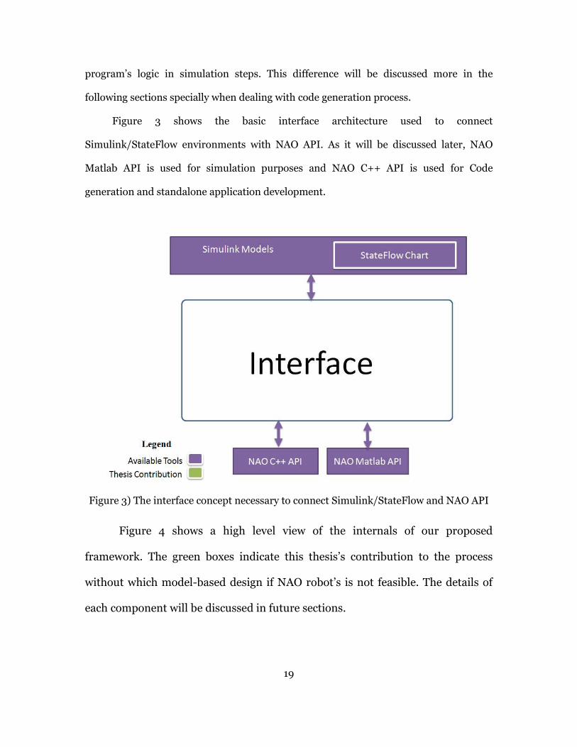
Figure 3 shows the basic interface architecture used to connect
Simulink/StateFlow environments with NAO API. As it will be discussed later, NAO
Matlab API is used for simulation purposes and NAO C++ API is used for Code
generation and standalone application development.
Figure 3) The interface concept necessary to connect Simulink/StateFlow and NAO API
Figure 4 shows a high level view of the internals of our proposed
framework. The green boxes indicate this thesis’s contribution to the process
without which model-based design if NAO robot’s is not feasible. The details of
each component will be discussed in future sections.

20
Figure 4) Internals of our interface framework
3.3 Implementation objectives
Currently engineering software such as MathWorks® products including Matlab®,
Simulink® and StateFlow® offer great tools and methodologies to model, simulate and
evaluate dynamic systems behavior. Diverse set of engineering toolboxes such as Control
design toolbox, computer vision toolbox, signal processing toolbox etc. help
programmers incorporate a great variety of algorithms from all engineering subjects into
their models. MathWorks® also provides code generation facilities called Matlab Coder®,
Simulink Coder® and StateFlow Coder® which previously were known as Real-time
Workshop®. These code generation tools allow engineers to generate C and C++ code for
target devices after they have developed their models and algorithms, simulated and
verified their correctness.

In this work, the objective is
developed for robotic applications using provided APIs has certain characteristics as well
as compile-time and run-time limitations that are missing from code generation facilities
of MathWorks® coder tools.
Coder® tools by creating a Simulink
(TLC) files which will include target robot APIs to generate ready
robots. For the StateFlow charts the same type
to be suitable for simulation and code generation within Simulink models.
chosen NAO robots from Aldebaran Robotics as our target platform because of its
powerful features, complete set of APIs, comprehensive document
For the high level use case, we are considering Robocup Standard Platform League (SPL)
competitions.
Figure 5) NAO H25 humanoid robot from Aldebaran Robotics
Even though the framework
made to create a comprehensive documentation as a generic guideline for
blocks and automated code generation so the methodology could be easily applied to
other robots such as iRobot Create and robotic
System (ROS) as well.
21
the objective is to facilitate development of robotic systems. The code
developed for robotic applications using provided APIs has certain characteristics as well
time limitations that are missing from code generation facilities
coder tools. We have tried to enhance the capabilities of Mathworks
tools by creating a Simulink® toolbox and related Target Language Compiler
(TLC) files which will include target robot APIs to generate ready-to-build code for our
For the StateFlow charts the same type of procedure has been developed in order
to be suitable for simulation and code generation within Simulink models.
from Aldebaran Robotics as our target platform because of its
powerful features, complete set of APIs, comprehensive documentation and ease of use.
level use case, we are considering Robocup Standard Platform League (SPL)
) NAO H25 humanoid robot from Aldebaran Robotics
framework is developed for NAO robots, a lot of effort has
to create a comprehensive documentation as a generic guideline for
automated code generation so the methodology could be easily applied to
other robots such as iRobot Create and robotic platforms such as Robot Operating
ic systems. The code
developed for robotic applications using provided APIs has certain characteristics as well
time limitations that are missing from code generation facilities
e capabilities of Mathworks
toolbox and related Target Language Compiler
build code for our
re has been developed in order
to be suitable for simulation and code generation within Simulink models. We have
from Aldebaran Robotics as our target platform because of its
ation and ease of use.
level use case, we are considering Robocup Standard Platform League (SPL)
a lot of effort has been
creating new
automated code generation so the methodology could be easily applied to
platforms such as Robot Operating
22
As it is explained in section 5, “The Proposed Solution”, after deeply investigating
robot programmers’ needs and capabilities and limitations of the software to be used, we
came up with a set of intermediate steps and a basic architecture for the framework to be
developed. The following is a brief list of these steps:
1. Developing a StateFlow® Interface API and a Simulink® toolbox for simulation
purposes which utilize the NAOqi Matlab API.
2. Developing a high level C/C++ Interface API acting as wrappers for NAO robots
based on the NAOqi API for facilitating the code generation process of high level
algorithms and behaviors. These classes act as an interface between the
automatically generated code and NAOqi API.
3. Developing a Simulink toolbox including blocks that resemble NAO API such as
initialization, motion, voice, vision for code generation purposes.
4. Creating appropriate Target Language Compiler (TLC) files for the automated
code generation of toolbox blocks mentioned in item 2.
5. Developing a procedure and accommodating documents that helps a beginner
start working with the developed framework quickly.

23
4 BACKGROUND MATERIAL
So far an effort has been made to clarify the problem we are facing and a big picture
of what we need and how we can approach the problem. But before starting to explain
the solution, since the proposed framework is taking advantage of many different
technologies, hardware and software and is trying to implement concepts such as model-
based design, it’s useful to have a brief overview of the methodologies as well as off-the-
shelf software, frameworks and hardware used as part of the solution.
4.1 An introduction to Model-Based Design
Model-based design is a powerful design methodology that relies on mathematical
models of systems to design, analyze, verify and validate the functionality of the system
[29]. Engineers start designing by inspecting the specification and requirement analysis.
In many cases the exact requirements are not identified at early stages of design and the
engineer has to rely on informal characteristics of the system. Model based design allows
users to start designing with minimal knowledge about the requirement.
4.1.1 Model based design
An important feature of model-based design is the ability to create modular
systems since the whole system is created using basic blocks. Using subsystem concept
one can achieve hierarchical design representing different layers of abstraction of the
system model. These feature let engineers to be able to encapsulate their subsystems’
functionality which helps in understanding the system as well as testing it.
4.1.2 Model-based design of cyber physical systems
Design of the Cyber Physical systems is more challenging than systems with only
computational units. When dealing with cyber physical systems, we have the element of
“Physical World”. To be able to precisely model the whole system, we need to specify the
24
characteristics of the outside world (Physical, electrical and mechanical systems) and
create a suitable model for them as well as for the computational elements.
4.1.3 Available platforms
Today there are many platforms and software available for Model-Based Design.
Most of these software have a graphical interface which resembles graphical sketches
used in design of feedback control systems or signal processing systems.
4.1.3.1 Simulink
Simulink® [2] from MathWorks® is an extension to Matlab® computing software
that enables modeling, analysis and simulation of dynamic systems. One can also
automatically generate C source code for real-time implementation of the models.
Simulink® also offers tools for systematic validation and verification of models through
requirement tractability, modeling style checking and model coverage analysis. Matlab®
and Simulink® are proprietary software and one should purchase each as well as the
required toolboxes and libraries. However there are some open source libraries and
toolboxes available for use in Matlab® and Simulink® such as “Matlab toolbox for the
iRobot Create” from United States Naval Academy [30] and TaLiRo Tools [31], [32]
from Cyber Physical Systems lab at Arizona State University which is a Matlab® toolbox
for analysis and falsification of hybrid automata and dynamical system models.
4.1.3.2 SciCos
Scicos [3] from Scilab is a free, open source modeling and simulation software. It
offers graphical modeling, compilation, simulation, and C code generation for hybrid
dynamical systems. In conjunction with Scicos-RTAI and Scicos-FLEX, one can generate
hard real-time control executables. Scicos models could also be integrated with the
Scilab programming language to enable scripting and batch processing of multiple

25
processing tasks. Models developed in Scicos could also be utilized in Scilab
programming language as functions. E4Coder is a commercial toolset extending
simulation and code generation capabilities of Scicos for embedded devices.
4.1.3.3 LabVIEW
LabVIEW® [33] from National Instruments® is a graphical programming
environment for instrumentation, system design, signal processing that uses block based
design and the data flow concepts. It resembles more of a visual programming platform
than modeling software. In fact LabVIEW® was initially created to allow non-
programmers to develop procedural programs without getting involved with coding as
“G programming language”. Capabilities of LabVIEW could be extended by installing
“Modules”. In fact to be able to fully model and simulate a dynamic system you need to
install the “Control design and Simulation Module (CDSim)”. Using MathScript node,
programmers are able to directly use a scripting language very close to Matlab® syntax.
National Instruments® also offers modules to interface LabVIEW® application with
other modeling and simulation software such as “LabVIEW® Simulation Interface
Toolkit” that allows users to compile Simulink® models for LabVIEW®.
4.1.3.4 MapleSim
MapleSim® from MapleSoft® is a multi-domain system level modeling and
simulation platform. One of the main pride points of MapleSim® is that it allows users to
specify, track, simulate and analyze the effect of changes and component-level parameter
tuning on the behavior of the system model.
26
4.2 NAO Robots
NAO is an autonomous programmable humanoid robot designed and
manufactured by Aldebaran Robotics. It offers a rapid development environment for
humanoid robotics. Since 2007 NAO robots are being used in Robocup Standard
Platform League (SPL) competitions succeeding AIBO four-legged robots from Sony.
There are various models of NAO developed, each suiting a specific application area. The
one used in academia and SPL competitions, NAO H25, has 25 degrees of freedom. In
the following sections features of this robot based on which this thesis is written, are
portrayed.
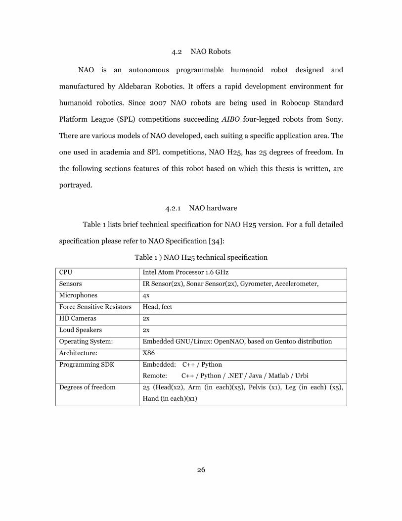
4.2.1 NAO hardware
Table 1 lists brief technical specification for NAO H25 version. For a full detailed
specification please refer to NAO Specification [34]:
Table 1 ) NAO H25 technical specification
CPU Intel Atom Processor 1.6 GHz
Sensors IR Sensor(2x), Sonar Sensor(2x), Gyrometer, Accelerometer,
Microphones 4x
Force Sensitive Resistors Head, feet
HD Cameras 2x
Loud Speakers 2x
Operating System: Embedded GNU/Linux: OpenNAO, based on Gentoo distribution
Architecture: X86
Programming SDK Embedded: C++ / Python
Remote: C++ / Python / .NET / Java / Matlab / Urbi
Degrees of freedom 25 (Head(x2), Arm (in each)(x5), Pelvis (x1), Leg (in each) (x5),
Hand (in each)(x1)
27
4.2.2 NAO Internals and Operating System
In this section we briefly explore the software internals of the NAO robots.
Understanding how a program is executed within NAO, helps users to better understand
and use the APIs as well as programming and configuring the robot.
An embedded software called NAOqi is always running on the robot on top of the
operating system and is responsible for managing robot modules, communications and
scheduling. NAOqi Software Development Kit (SDK) is a set of Application
Programming Interfaces (API) provided in several languages such as C++, Python,
Matlab®, Java and Urbi that help programmers develop application for NAO. The SDK
also is supplied alongside with a build system called qiBuild which is created based on
CMake and is responsible for project management, build and debugging the applications
written using the C++ SDK.
4.2.2.1 NAO operating system
NAO has a full-fledged computer embedded in its head utilizing an Atom
processor and running an embedded operating system called OpenNAO. OpenNAO is
developed explicitly for NAO robots and is based on the Gentoo Linux distribution. The
operating system is equipped with libraries and programs necessary to run NAO
programs.
There are two default Linux users defined with usernames “nao” and “root”. The
later has root privileges. It is possible to connect to the robot using an SSH client getting
access to the robot’s operating system command line as well as the file system.
4.2.2.2 NAOqi Software
NAOqi [35] is the main program residing on the NAO that is responsible for
managing resources in a higher level and provides an abstraction for the hardware and
operating system through software components called modules and also the APIs.

28
NAOqi includes a reliable, fast, cross-platform robotic framework, NAOqi Framework
[36], for developers to enhance the capabilities and functionalities of NAO. NAOqi
supports all requirements of a robotic application such as parallelism, resource
management, event handling and synchronization.
4.2.2.3 How NAOqi Works
NAOqi system provides system processes called “Modules” that are considered as
main interactive components of the robot’s functionalities. Each module is responsible
for taking care of a specific capability of the robot such as motion, text or speech
processing, vision, etc. and provides the interface for high level layer to interact with the
hardware and implement those functionalities.
Using the provided API’s, programmer creates appropriate “Proxy” objects that are used
to call the functions and services provided by the “Modules”.
Different levels of abstraction presented by NAOqi SDK will be a useful feature
for code generation. However, in many cases, for model based design we need to ignore
many underlying details and that is why we decided to create higher level classes in C++
which basically will function as wrappers for lower level functionalities and services. ROS
(Robot Operating System) users can think of NAOqi as ROS core and modules as ROS
packages/Nodes.
4.2.3 Programming NAO
There are various ways to exploit the capabilities of NAO robots and program it
for a specific task. First of all note that one can either use a simulated environment or an
actual real-world NAO to test the developed algorithms. In this project, both simulation
environment and real robots are considered as the target for code generation. Again we
have two choices for controlling NAO:
• Remote execution of the code from a desktop computer
29
• Building and downloading the code on the NAO and execute a local standalone
program
In both cases we need to use the NAO API which is provided as NAOqi Software
Development Kit and write the programs in either of the following languages: C++,
Python, Matlab, Java, .Net. However NAO only supports local execution of C++ and
Python code, the rest need to be executed on a host desktop/laptop computer and send
commands to NAOqi system either via Wi-Fi or Ethernet.
The following summarizes the above programming paths for programming NAO:
• Simulation (Webots, RoboCup Soccer Server 3D- RCSS3D, etc.)
o High level software (Choregraphe)
o Programming using SDK (Matlab, Python, C++, Java, .NET)
• Actual NAO
o Remote execution
� High level software (Choregraphe)
� Programming using SDK (Matlab, Python, C++, Java, .NET)
o Local execution (On the NAO; Python SDK, C++ SDK)
4.2.4 Choregraphe® and Monitor®
Choregraphe® [37] is a high level block based programming environment to
develop applications for NAO. It is used to create and edit movement and behaviors
using its intuitive graphical environment. The blocks are programmed to implement
behaviors from joint movements to high level posture transitions, walking algorithms
and even object tracking all in one simple to use block. As in LabVIEW® and Simulink®
environments, Choregraphe® takes advantage of execution flow concepts and the block
execution order is dependent to the order in which they are connected to each other.
Figure 6 shows a screenshot of Choregraphe software connected to an actual NAO.
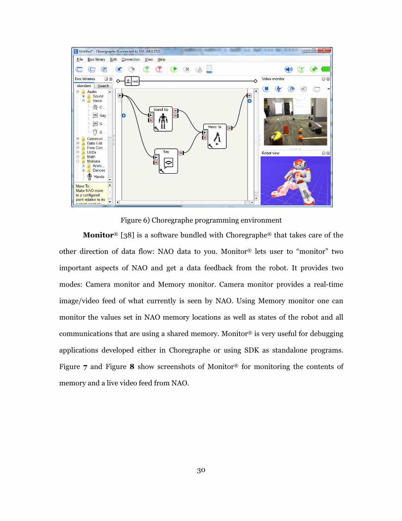
30
Figure 6) Choregraphe programming environment
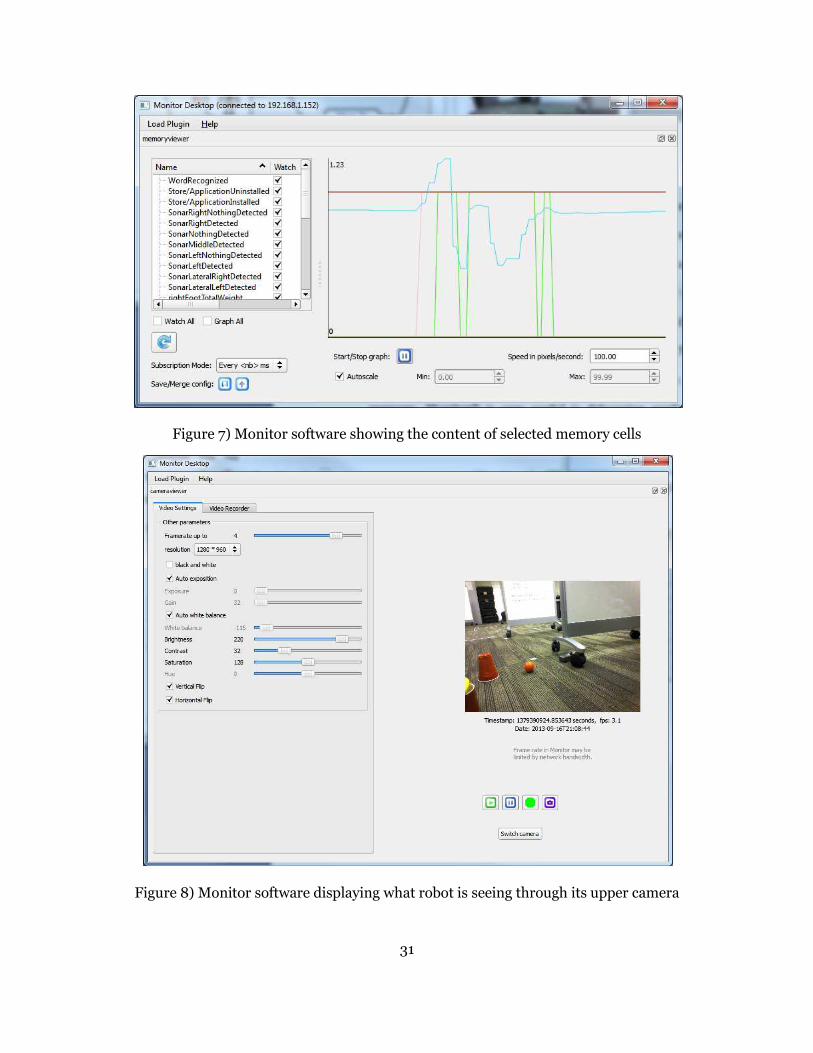
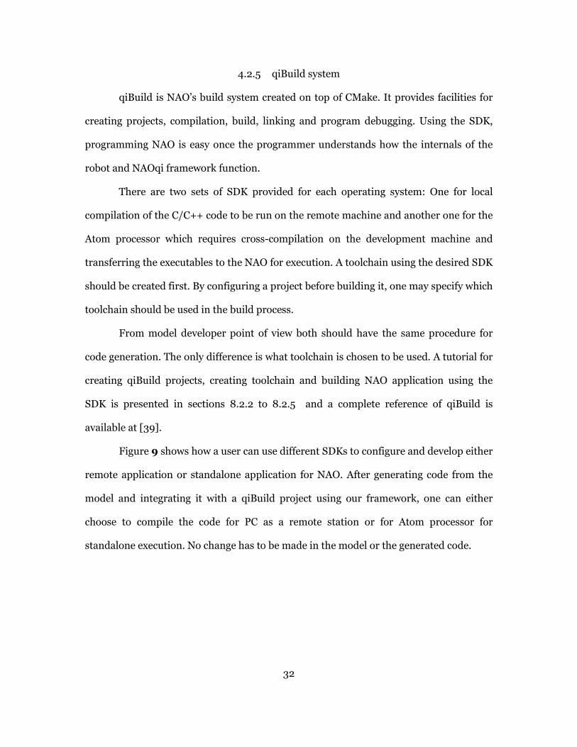
Monitor® [38] is a software bundled with Choregraphe® that takes care of the
other direction of data flow: NAO data to you. Monitor® lets user to “monitor” two
important aspects of NAO and get a data feedback from the robot. It provides two
modes: Camera monitor and Memory monitor. Camera monitor provides a real-time
image/video feed of what currently is seen by NAO. Using Memory monitor one can
monitor the values set in NAO memory locations as well as states of the robot and all
communications that are using a shared memory. Monitor® is very useful for debugging
applications developed either in Choregraphe or using SDK as standalone programs.
Figure 7 and Figure 8 show screenshots of Monitor® for monitoring the contents of
memory and a live video feed from NAO.
31
Figure 7) Monitor software showing the content of selected memory cells
Figure 8) Monitor software displaying what robot is seeing through its upper camera
32
4.2.5 qiBuild system
qiBuild is NAO’s build system created on top of CMake. It provides facilities for
creating projects, compilation, build, linking and program debugging. Using the SDK,
programming NAO is easy once the programmer understands how the internals of the
robot and NAOqi framework function.
There are two sets of SDK provided for each operating system: One for local
compilation of the C/C++ code to be run on the remote machine and another one for the
Atom processor which requires cross-compilation on the development machine and
transferring the executables to the NAO for execution. A toolchain using the desired SDK
should be created first. By configuring a project before building it, one may specify which
toolchain should be used in the build process.
From model developer point of view both should have the same procedure for
code generation. The only difference is what toolchain is chosen to be used. A tutorial for
creating qiBuild projects, creating toolchain and building NAO application using the
SDK is presented in sections 8.2.2 to 8.2.5 and a complete reference of qiBuild is
available at [39].
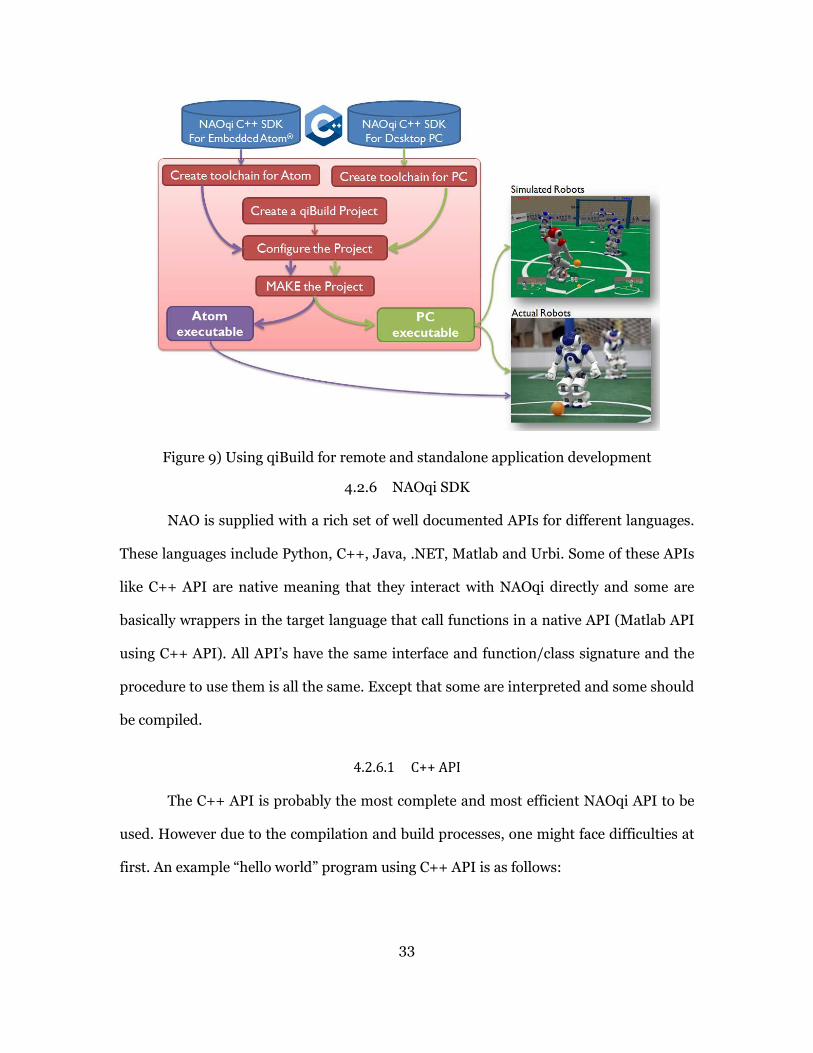
Figure 9 shows how a user can use different SDKs to configure and develop either
remote application or standalone application for NAO. After generating code from the
model and integrating it with a qiBuild project using our framework, one can either
choose to compile the code for PC as a remote station or for Atom processor for
standalone execution. No change has to be made in the model or the generated code.
33
Figure 9) Using qiBuild for remote and standalone application development
4.2.6 NAOqi SDK
NAO is supplied with a rich set of well documented APIs for different languages.
These languages include Python, C++, Java, .NET, Matlab and Urbi. Some of these APIs
like C++ API are native meaning that they interact with NAOqi directly and some are
basically wrappers in the target language that call functions in a native API (Matlab API
using C++ API). All API’s have the same interface and function/class signature and the
procedure to use them is all the same. Except that some are interpreted and some should
be compiled.
4.2.6.1 C++ API
The C++ API is probably the most complete and most efficient NAOqi API to be
used. However due to the compilation and build processes, one might face difficulties at
first. An example “hello world” program using C++ API is as follows:

34
#include <alproxies/altexttospeechproxy.h>
int main(int argc, char* argv[]){
AL::ALTextToSpeechProxy tts("192.168.1.155", 9559 );
tts.say(“Hello World!”);
return 0;}
As shown in the code snippet, An object of class ALTextToSpecchProxy is created
and a method on that object is called with appropriate arguments and that is all you need
to code to make NAO “say” something. However you need to go through the project
creation and build using qiBuild build system to be able to compile this code.
NAO API is composed of different sets of APIs each of which is dedicated to fulfill
a specific purpose. For example ALMotionProxy class is intended to take care of most of
motion-related behavior of the robot and ALRobotPostureProxy makes the robot switch
smoothly between various predefined postures such as “StandUp”, “SitDown”,
“LayBack”, etc. Example API classes and some associated methods are listed in Table 2.
Table 2) Example NAO API classes and associated methods
API name Sample methods
Stiffness Control API � ALMotionProxy::setStiffnesses()
� ALMotionProxy::getStiffnesses()
Joint Control API � ALMotionProxy::setAngles()
� ALMotionProxy::getAngles()
� ALMotionProxy::closeHand()
� ALMotionProxy::openHand()
Locomotion control API � ALMotionProxy::walkTo()
� ALMotionProxy::moveInit()
� ALMotionProxy::move()
A complete reference of ALMotionProxy API is available at [40]. You have to note
in the motion category there are ALRobotPosture and ALRobotNavigation classes also
available. There also exists other API for Core functionality, Audio, Vision, Sensors and
Tracking [41].
35
4.2.6.2 Python API
Using Python API is probably the best place to start working with NAO robots
since the API installation and integration with the Python environment is very
straightforward and it needs no compilation. An example usage of the API for the NAO
to say “Hello World” is presented here:
from naoqi import ALProxy
tts = ALProxy("ALTextToSpeech", "192.168.1.155”, 95 59)
tts.say("Hello world")
4.2.6.3 Matlab API
Most of NAO APIs are native classes and functions written and compiled in the
target language. However NAOqi Matlab API provided by Aldebaran Robotics for NAO is
not a native API. NAO Matlab API is actually a series of Matlab classes and function
wrappers that utilize a compiled version of C++ API through a compiled MEX file which
will be described later. We should note that the MEX C++ files provided and compiled by
Aldebaran is only a bridge between C++ API and Matlab wrapper functions.
As it will be explained in section 4.3.5, a MEX file is a dynamically linked library
file that is consist of a gateway function named “mexFunction()” which is the entry point
by Matlab engine. This function is considered the “main” function of the program. All
other C/C++ functions are called from this function. Based on the gateway nature of this
type of files, there is an interface to Matlab® workspace variables.
After installation of NAOqi Matlab API, the piece of code needed to implement
the ‘Hello World” program in Matlab is basically the same as C++ and Python as shown
below:
tts = ALTextToSpeechProxy('192.168.1.155',9559);
tts.insertData('Hello World');

36
Let’s take a deeper look at this piece of code. The ALTextTOSpeechProxy()
function is the constructor of a class with the same name defined as follows in a Matlab
file, ALTextToSpeechProxy.m:
Order of usage Function call
classdef ALTextToSpeechProxy < handle % class definition
properties (GetAccess='public', SetAccess='priv ate')
ptrProxyNaoQi;
end
methods
function obj=ALTextToSpeechProxy(ip, port) % constructor definition
obj.ptrProxyNaoQi = matlabproxy('ALText ToSpeech',ip,port);
end
ALTextTOSpeechProxy()
[in NAO Matlab API]
matlabproxy()
[in the MEX file; matlabproxy.cpp
YourMainFunction()
ALProxyRemote()
[in NAOqi C++ API ]
Obj.say()
[in NAO Matlab API]
matlabcall()
[in the MEX file: matlabcall.cpp ]
YourMainFunction()
genericCall()
[in NAOqi C++ API ]
Creating Object Calling Object method

37
% ... [rest of the code omitted]
function say(obj, varargin) % SAY meth od definition
matlabcall(obj.ptrProxyNaoQi, 'say', va rargin);
end
% ... [rest of the code omitted]
The constructor is calling matlabproxy() function which is a compiled MEX
function. The main line of code inside matlabproxy() MEX file is the following which is
responsible for creating a ALProxyRemote object for a specific module using NAO C++
API:
ALProxyRemote *proxy = new ALProxyRemote(moduleName , ip, port);
The complete source for matlabproxy.cpp used to create the MEX function is available in
APPENDIX .
Once the object for the action is created inside MEX function and is passed to
the Matlab environment, one can call the methods associated with it. For the methods
called from Matlab® code, another MEX function named “matlabcall()” is called which
makes a call to the C++ API function “genericCall()”.
The source code for matlabcall.cpp is presented in APPENDIX .
4.2.7 Implementing simple behaviors using NAOqi Matlab® API
Here we show how to use the Matlab® API to implement simple behaviors. This is
necessary to understand how the API works so later when the code generation tools and
process is discussed, the procedure is more comprehensible.
As with all other APIs, to make NAO do something, first we need to create an
object of that type of behavior ( e.g. Motion, Speech, Vision, etc.) and then call the
methods of the class on the object.
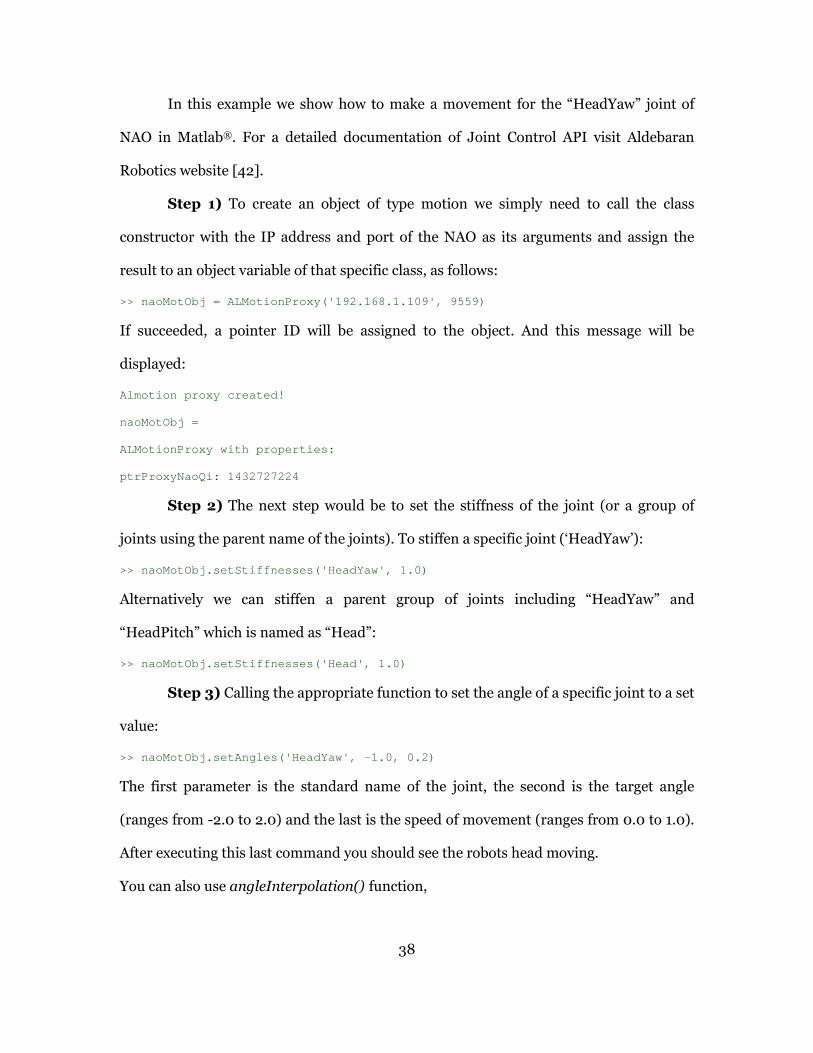
38
In this example we show how to make a movement for the “HeadYaw” joint of
NAO in Matlab®. For a detailed documentation of Joint Control API visit Aldebaran
Robotics website [42].
Step 1) To create an object of type motion we simply need to call the class
constructor with the IP address and port of the NAO as its arguments and assign the
result to an object variable of that specific class, as follows:
>> naoMotObj = ALMotionProxy('192.168.1.109', 9559)
If succeeded, a pointer ID will be assigned to the object. And this message will be
displayed:
Almotion proxy created!
naoMotObj =
ALMotionProxy with properties:
ptrProxyNaoQi: 1432727224
Step 2) The next step would be to set the stiffness of the joint (or a group of
joints using the parent name of the joints). To stiffen a specific joint (‘HeadYaw’):
>> naoMotObj.setStiffnesses('HeadYaw', 1.0)
Alternatively we can stiffen a parent group of joints including “HeadYaw” and
“HeadPitch” which is named as “Head”:
>> naoMotObj.setStiffnesses('Head', 1.0)
Step 3) Calling the appropriate function to set the angle of a specific joint to a set
value:
>> naoMotObj.setAngles('HeadYaw', -1.0, 0.2)
The first parameter is the standard name of the joint, the second is the target angle
(ranges from -2.0 to 2.0) and the last is the speed of movement (ranges from 0.0 to 1.0).
After executing this last command you should see the robots head moving.
You can also use angleInterpolation() function,

39
>> naoMotObj.angleInterpolation('HeadYaw', [1.0, -1 .0, 0.0], [5.0, 15.0, 25.0],
true)
The first argument specifies the joint. The second is a list of angles to be traversed
based on the corresponding times list as the next argument and the last argument is a
Boolean that denotes if the angles are absolute or the values are relative to the current
angle. In the above example, the ‘HeadYaw’ joint will go to the angle 1.0 at time 5.0 then
keeps moving “such that” it will be at angle -1.0 at time 15.0 (10 seconds later) and then
keeps moving till it is positioned at angle 0.0 at time 25. So the whole process takes
exactly 25 seconds from the beginning. This function smoothens the joint movement by
using interpolations.
Step 4) When you are done using a joint or a group of joints, you should
“unStiff” the joint(s) in order to avoid the motors to heat up as well as decreasing the
power consumption. You “Un-Stiff” a joint or set of joints using the same function but
calling it with a value of zero:
>> naoMotObj.setStiffnesses('Head', 0.0)
This command “un-stiffens” the “Head” joint group which includes “HeadYaw” and
“HeadPitch”.
In this section, the basic concepts and tools of programming simple NAO
behavior is briefly explained which will be used to understand the procedure of code
generation from Simulink® models and StateFlow® chart. Complete NAO SDK reference
and programming guide is available at [43].
40
4.3 MathWorks® Software
To develop a complete framework it was necessary to utilize a set of fully trusted
and reliable tools and software. Matlab®, Simulink®, Matlab Coder®, Simulink Coder®,
StateFlow® and StateFlow coder® are products from MathWorks® that this thesis heavily
relies on to produce a framework for modeling, simulation and automatic code
generation for NAO robots. In this section we briefly introduce these software and their
characteristics.
4.3.1 Simulink® and StateFlow®
Simulink® is a software tool for modeling and simulation of dynamic reactive
systems. It is developed as an extension to Matlab®. Capabilities of Simulink® could be
easily enhanced by installing hardware and software products from MathWorks® as well
as third-party developers. StateFlow® is one of the official extensions of Simulink® that
provides an environment for developing state machines and flowcharts. Simulink® also
has Support Packages for a number of embedded and robotic systems such as Lego
Mindstorms NXT, BeagleBoard, Raspberry Pi and Arduino boards. Support packages
provide more capabilities than a simple library. An engineer can develop a model using
these packages, simulate and run the model on the target hardware directly from
Simulink® environment without getting involved with the code generation and
compilation process and also monitor the signals and variable from within Simulink®
environment.
StateFlow® is a toolbox within Simulink® that allows adding modal systems and
defining Finite State Machine charts inside our models to model dynamic reactive
systems. If a system has no operating modes, the system is stateless. If a system has
operating modes, the system is modal.

41
There are already hundreds of proprietary and open source toolboxes developed
to be used with Simulink® for different purposes such as planning, control law
integration, verification and validation, vision etc. Some of these libraries also support
automatic code generation for models containing their blocks. One of the benefits of
using Simulink® and StateFlow® is being able to use the third-party tools that are
already developed, debugged and verified such as Robotic toolbox [44] for incorporating
basic locomotion and planning algorithms, S-TaLiRo [45] for verifying complex temporal
properties of Cyber Physical Systems and LROMP [46] for robust optimal multi-
robot planning with temporal logic constraint. Having a large variety of toolboxes and
add-ons for Simulink® makes it a good choice for modeling, simulation and development
of robotic applications, at least in university environments where access to the Matlab®
platform is provided.
4.3.2 Understanding Simulink® simulation
Before we dive into the modeling, simulation and code generation, let’s see how
Simulink® simulates a model of a dynamic system. Getting started to work with
Simulink® and understanding how the simulations work could be a little different for
computer science students who are more comfortable with structured procedural
programming in languages such as C++ or Python. User needs to know that what a
simulation is, how Simulink® simulates a model, what a solver is, what a time step and
step size are, and first of all what a signal is and how these properties map to the
generated code as a procedural program. In Figure 10 the flow chart of a Simulink®
simulation is illustrated.

42
Figure 10) Simulation flow chart using Simulink
When the simulation starts, as the first step, the model compiler is invoked and
the model is initialized. Then simulation phases begin which are described next [47].
1. Model compilation
Model compiler performs a series of task as follows: The block parameters’ values as
well as signal attributes are calculated and determined. A process called attribute
propagation is performed to resolve the unspecified attributes in the model. Model is
flattened if there are any virtual subsystems available and block reduction optimizations
are carried out.
2. Link phase
In link phase, necessary memory is allocated and initialized for the model states,
signals and parameters. In this phase methods of model’s blocks are listed to find out the
most efficient order of execution for computing each block’s output. Priorities and
execution order of blocks are also determined in this phase.
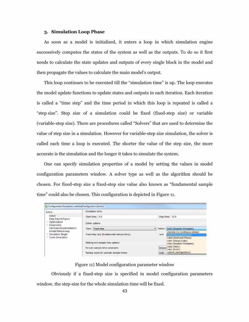
43
3. Simulation Loop Phase
As soon as a model is initialized, it enters a loop in which simulation engine
successively computes the states of the system as well as the outputs. To do so it first
needs to calculate the state updates and outputs of every single block in the model and
then propagate the values to calculate the main model’s output.
This loop continues to be executed till the “simulation time” is up. The loop executes
the model update functions to update states and outputs in each iteration. Each iteration
is called a “time step” and the time period in which this loop is repeated is called a
“step size”. Step size of a simulation could be fixed (fixed-step size) or variable
(variable-step size). There are procedures called “Solvers” that are used to determine the
value of step size in a simulation. However for variable-step size simulation, the solver is
called each time a loop is executed. The shorter the value of the step size, the more
accurate is the simulation and the longer it takes to simulate the system.
One can specify simulation properties of a model by setting the values in model
configuration parameters window. A solver type as well as the algorithm should be
chosen. For fixed-step size a fixed-step size value also known as “fundamental sample
time” could also be chosen. This configuration is depicted in Figure 11.
Figure 11) Model configuration parameter window
Obviously if a fixed-step size is specified in model configuration parameters
window, the step-size for the whole simulation time will be fixed.

In the next sections when discussing code generation, the suitable configuration
that should be set for models as well as how these settings affect the generated code, are
explained.
4.3.3 Signals in simulation and mapping t
A signal is a “Variable” that
different from a vector or an array in Simulink
model shown in Figure 12 and the result of simulation for 10 second i
Figure 12) A simple Simulink model without a time
Figure 13
When we start the simulation, Simulink
models and blocks and then begins going through a “simulation loop”. in each iteration,
Simulink® reads a value from the “Gain” input which is the constant value “1” calculates
44
In the next sections when discussing code generation, the suitable configuration
that should be set for models as well as how these settings affect the generated code, are
Signals in simulation and mapping to the generated code
signal is a “Variable” that its value changes over time. So this concept
different from a vector or an array in Simulink®. For example consider the following
and the result of simulation for 10 second in Figure
) A simple Simulink model without a time-varying signal
13) Simulation result for the above model
When we start the simulation, Simulink® first initializes the necessary variables,
models and blocks and then begins going through a “simulation loop”. in each iteration,
reads a value from the “Gain” input which is the constant value “1” calculates
In the next sections when discussing code generation, the suitable configurations
that should be set for models as well as how these settings affect the generated code, are
o the generated code
this concept is
le consider the following
Figure 13.
varying signal
first initializes the necessary variables,
models and blocks and then begins going through a “simulation loop”. in each iteration,
reads a value from the “Gain” input which is the constant value “1” calculates
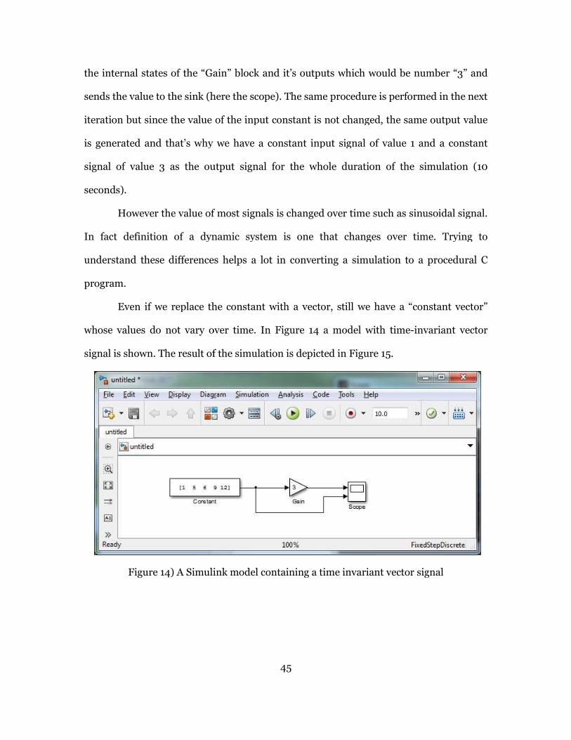
the internal states of the “Gain” b
sends the value to the sink (here the scope). The same procedure is performed in the next
iteration but since the value of the input constant is not changed, the same output value
is generated and that’s why we have a constant input signal of value 1 and a constant
signal of value 3 as the output signal for the whole duration of the simulation (10
seconds).
However the value of
In fact definition of a dynamic system is one that changes over time. Trying to
understand these differences helps a lot in converting a simulation to a procedural C
program.
Even if we replace the constant with a
whose values do not vary over time.
signal is shown. The result of the simulation is depicted in
Figure 14) A Simulink model containing a time invariant vector signal
45
the internal states of the “Gain” block and it’s outputs which would be number “3” and
value to the sink (here the scope). The same procedure is performed in the next
iteration but since the value of the input constant is not changed, the same output value
why we have a constant input signal of value 1 and a constant
signal of value 3 as the output signal for the whole duration of the simulation (10
the value of most signals is changed over time such as sinusoidal signal.
of a dynamic system is one that changes over time. Trying to
understand these differences helps a lot in converting a simulation to a procedural C
Even if we replace the constant with a vector, still we have a “constant vector”
over time. In Figure 14 a model with time-invariant vector
signal is shown. The result of the simulation is depicted in Figure 15.
) A Simulink model containing a time invariant vector signal
ld be number “3” and
value to the sink (here the scope). The same procedure is performed in the next
iteration but since the value of the input constant is not changed, the same output value
why we have a constant input signal of value 1 and a constant
signal of value 3 as the output signal for the whole duration of the simulation (10
sinusoidal signal.
of a dynamic system is one that changes over time. Trying to
understand these differences helps a lot in converting a simulation to a procedural C
, still we have a “constant vector”
invariant vector
) A Simulink model containing a time invariant vector signal
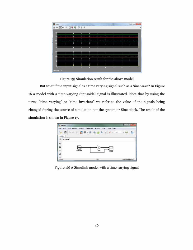
Figure 15
But what if the input signal is a time varying signal
16 a model with a time-varying Sinusoidal signal is illustrated. Note that by using the
terms “time varying” or “time invariant” we refer to the value of the signals being
changed during the course of simulation not the system or Sin
simulation is shown in Figure
Figure 16) A Si
46
15) Simulation result for the above model
the input signal is a time varying signal such as a Sine wave?
varying Sinusoidal signal is illustrated. Note that by using the
terms “time varying” or “time invariant” we refer to the value of the signals being
rse of simulation not the system or Sine block. The result of the
Figure 17.
) A Simulink model with a time varying signal
Sine wave? In Figure
varying Sinusoidal signal is illustrated. Note that by using the
terms “time varying” or “time invariant” we refer to the value of the signals being
block. The result of the

Figure 17
The model shown in
Fixed step size with no continuous states and the
By setting this to auto, based on a
between the calculations of each “time
common denominator of the specified sample times in the model
time of the model).
Figure 18) Simulation configuration for the last model
To make the simulation and how it works more clear, lets increase this fixed
size to a greater value such as 0.5 (seconds) instead of auto. The result of
is displayed in Figure 19.
47
17) Simulation result for the above model
shown in Figure 16 is simulated using the following setting:
size with no continuous states and the value of fixed-step size is set to “auto”.
By setting this to auto, based on a specific formula, Simulink calculates the “step time”
of each “time-step” and normally it is equal to the least
common denominator of the specified sample times in the model (fundamental sample
) Simulation configuration for the last model
To make the simulation and how it works more clear, lets increase this fixed
size to a greater value such as 0.5 (seconds) instead of auto. The result of the
using the following setting:
step size is set to “auto”.
calculates the “step time”
is equal to the least
(fundamental sample
To make the simulation and how it works more clear, lets increase this fixed-step
the simulation

.
Figure 19) The result of using a larger simulation step
Now that we have bigger step
10 the model is evaluated and the lines are drawn using a simple interpolation. So we can
say the simulation has iterated through the simulation loop 11 times.
For a more detailed explanation of this procedure
Systems” [47] and “Modeling Dynamic Systems
4.3.4
MathWorks® Coder®
used with Matlab® and Simulink
known as “Real-Time Workshop
and adding new features it was split
known as “Matlab Coder®”,
Figure 20.
48
) The result of using a larger simulation step-size
Now that we have bigger step-sizes, it is obvious that only at times 0,
10 the model is evaluated and the lines are drawn using a simple interpolation. So we can
say the simulation has iterated through the simulation loop 11 times.
detailed explanation of this procedure, visit “Simulating Dynamic
Modeling Dynamic Systems” [48].
4.3.4 MathWorks® Coder® products
® products are the next generation of code generation facility
and Simulink® [49]. Before version R2011a the whole package was
Time Workshop®” and “Embedded Coder®”. After some improvement
adding new features it was split and restructured into three separate
, “Simulink Coder®” and “Embedded Coder®” as shown in
0, 1, 2, … and
10 the model is evaluated and the lines are drawn using a simple interpolation. So we can
visit “Simulating Dynamic
products are the next generation of code generation facility
R2011a the whole package was
fter some improvement
into three separate products
” as shown in
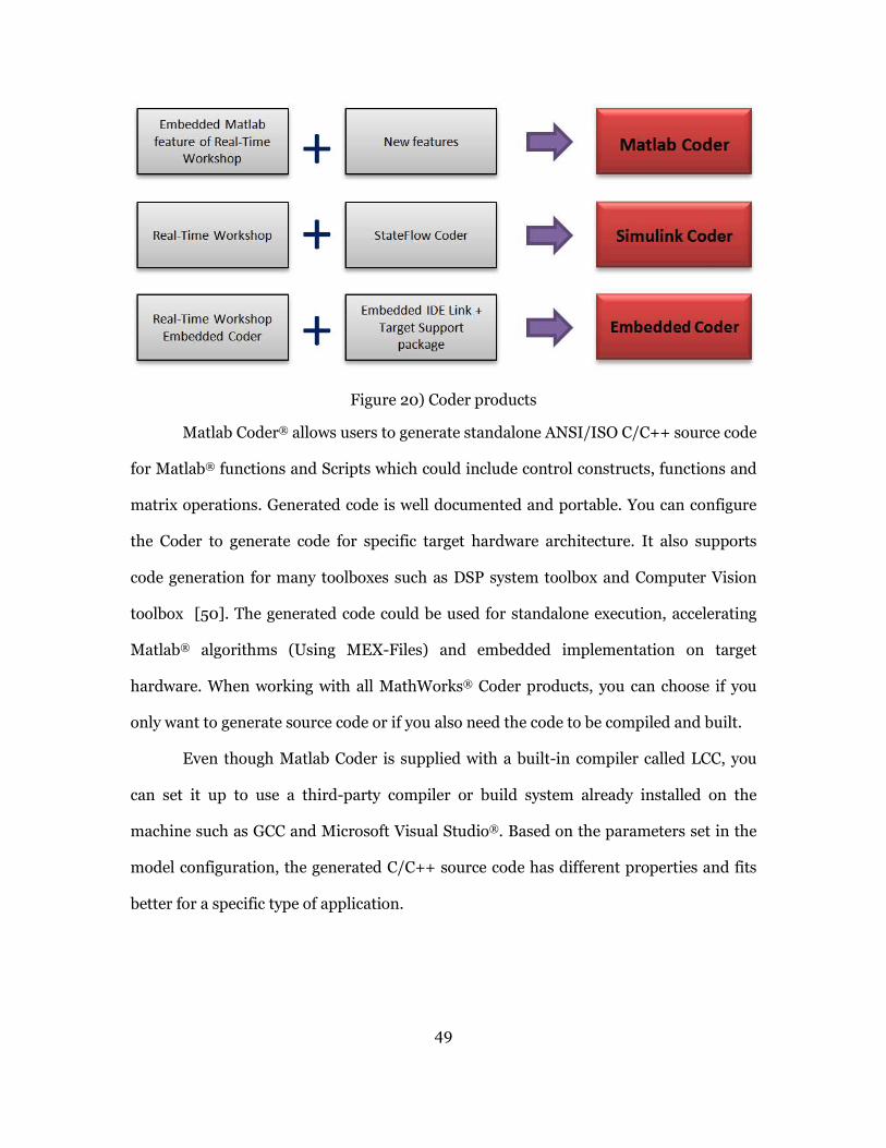
49
Figure 20) Coder products
Matlab Coder® allows users to generate standalone ANSI/ISO C/C++ source code
for Matlab® functions and Scripts which could include control constructs, functions and
matrix operations. Generated code is well documented and portable. You can configure
the Coder to generate code for specific target hardware architecture. It also supports
code generation for many toolboxes such as DSP system toolbox and Computer Vision
toolbox [50]. The generated code could be used for standalone execution, accelerating
Matlab® algorithms (Using MEX-Files) and embedded implementation on target
hardware. When working with all MathWorks® Coder products, you can choose if you
only want to generate source code or if you also need the code to be compiled and built.
Even though Matlab Coder is supplied with a built-in compiler called LCC, you
can set it up to use a third-party compiler or build system already installed on the
machine such as GCC and Microsoft Visual Studio®. Based on the parameters set in the
model configuration, the generated C/C++ source code has different properties and fits
better for a specific type of application.

50
4.3.5 Matlab® Executables (MEX-Files)
Using MEX (Matlab Executable [51]) a Matlab® programmer can execute C, C++
and Fortran code from Matlab® environments as if they were built-in Matlab® function.
Binary MEX files are user defined dynamically linked libraries that are generated using
MEX utility. MEX functions are also generated using Matlab® Coder and the same
configuration applies for both procedures.
A MEX source file is basically a C source code written based on a specific
structure and rules. A MEX source file should include a entry function named
mexFunction() that acts as the entry point of the routine and also as a bridge between
Matlab® and the binary MEX file. mexFunction() has the following signature:
void mexFunction( int nlhs, mxArray *plhs[],
int nrhs, const mxArray *prhs[] )
From inside mexFunction() you can call other C functions while passing input
parameters received from Matlab® environment using “prhs” array and sending back the
results to Matlab using “plhs” array. “prhs” stands for Pointer to the Right Hand Side
elements (inputs) and “plhs” stands for Pointer to the Left Hand Side elements
(Outputs). nrhs and nlhs arguments specify the number of input and output parameters,
respectively. These parameters are passed to and used by the mexFunction() in
run-time. Calling method of a MEX function is the same as calling a Matlab® function
and the name of the MEX file is considered the name of the function.
NAO Matlab API is written using this method, details of which is explained in section
4.2.6.3.
4.3.6 Simulink Coder® and Embedded Coder®
There are some automated code generation tools available for automatically
generating source code and executables from Simulink® models. The most prominent
51
one, Simulink Coder® formerly known as Real-Time Workshop®, is a subset of
Simulink® software that takes care of all tasks related to generating and compiling
S-Functions, generating code and compilation as well as debugging the code. Another
well-known commercial software tool that is used as a code generator for Simulink is
TargetLink® from dSpace® corporation [52] which is used for ANSI/ISO C as well as
production code generation optimized for specific processors. It also supports
AUTOSAR-compliant code for automotive applications [53].
Embedded Coder enhances capabilities of the two other Coder products by
generating embeddable code for Matlab® scripts and Simulink® models that is optimized
for use on embedded systems and processors.
4.3.6.1 Building a Simulink® model
Simulink Coder® makes the process of code generation very easy. In this section
the procedure of generating code from Simulink® models are explained on top of which
we build our framework.
4.3.6.2 Building® a Simulink block/sub system
There are times that you only need to generate code for a particular part of your
model, or a subsystem, instead of for the whole model. One reason is to replace the
subsystem with the equivalent S-Function to speed up the execution of that part of your
model. Since the subsystem is replaced with a compiled S-function, in complex cases you
can accelerate your model. The acceleration is noticeable if that part is computationally
intensive and has features such as highly iterative loops, a lot of hardware interaction or
comprises a notable amount of dynamic memory allocation.
The other reason for generating code for a subsystem is creating libraries and
reusable blocks that we can reuse later in further projects as well as implementing that
code on the actual hardware.

52
In this project as a part of developing the framework, it was necessary to build a
Simulink library consisting of basic reusable blocks that engineers could make use of in
their projects and later be able to generate code for that model.
As mentioned earlier, when the Simulink coder® is called to generate code for a
whole model, it takes steps such as model checking, flattening the virtual subsystems and
then it moves to generating code for the model. To do so, Simulink Coder® firsts needs to
know what is the equivalent C/C++ code for each single block. When this is clear, then it
can proceed and generate code for the whole model.
By setting a subsystem as “Atomic”, Simulink® treats the subsystem as a unit
when determining the execution order of block methods. After setting a subsystem as an
atomic unit, you have the option of configuring the code generation parameters of it as
well. Figure 21 shows the existing options for packaging of a subsystem in the generated
code.
Figure 21) configuring the packaging setting of a subsystem
“Inline” value embeds the body functionality of the subsystem within the source
of model’s main step function. “Nonreusable function”, generates a function without
arguments for the subsystem and it only acts on global variables. By setting this option to
“Reusable function” Simulink Coder® creates a function in a separate file that takes input
arguments so it could be used multiple times in different contexts.

53
Here we should be reminded of the importance of modular design in both
creating a library as well as creating engineering models. Based on this engineering
design principle, and by iterating the code generation process for simple blocks, we
realized that by labeling our blocks as “Reusable Atomic Subsystem” the code generated
by Simulink coder is more modular, more readable and it will be easier to debug and
maintain.
4.3.6.3 S-Functions
Using S-Functions [54] we can extend the capabilities of Simulink® and
implement our algorithms and add custom blocks to our models. S-functions utilize
MEX files (Which could be written in Matlab, C or C++) and are developed based on a
special format using “S-Function API”. Simulink® engine dynamically loads S-Functions
while executing the models.
S-Functions support implementation of continuous, discrete and hybrid systems. We
can also use S-Functions with code generation products and even customize the
generated code for those blocks by writing tailored TLC files.
An S-Function is composed of a series of call-back methods called by the simulation
engine in each simulation stage to perform a specific task or algorithm. These call-back
functions cover initialization, calculating next time step, calculation of outputs. Updating
states and integration for the block. There are two types of S-Functions:
• Matlab S-Functions
• C-Mex S-Functions
Matlab S-Functions (Level-2) are easier and faster to develop and have easier access
to Matlab® toolbox functions while avoiding the time-consuming compile-link-execute
cycle. C-MEX S-Functions are better for integrating legacy C-Code and it may simulate
faster than Matlab® S-Functions. We have used Matlab® S-Functions to develop the NAO

54
Simulink® library for simulation and have used C S-Functions for developing the NAO
Simulink® library for code generation.
4.3.6.4 Creating and using S-Functions
As the initial idea we decided to use the NAO Matlab APIs and created Simulink
blocks for NAO. In this way, we could create models and simple control algorithms in
Simulink®, simulate the system as a hardware-in-the-loop system. This method is not
the best way to create Simulink® blocks to utilize the NAO APIs because we cannot
generate code from Matlab S-functions that call MEX functions. However, we realized
that first creating blocks using this method helps us create C-MEX S-function blocks that
are suitable for code generation as well.
4.3.6.5 Available S-Function Implementations
You can create S-functions in one of the following ways [55]:
• A Level-1 MATLAB S-function
• A Level-2 MATLAB S-function
• A handwritten C-MEX S-function
• The S-Function Builder (C-MEX)
• The Legacy Code Tool
Level-1 Matlab S-Functions implement older version of S-Function API and lack
many of the power of the newer API implemented in level-2 Matlab S-Functions.
Hand-written S-Functions requires a great knowledge about the S-Function API and the
simulation procedure and finally legacy code tool is used for simple S-Functions. The
blocks to create S-Functions of different types are shown in Figure 22.

55
After investigations and creating examples, it was determined that the most flexible,
easiest and robust method suitable for developing our framework is to use
“The S-Function Builder”.
Figure 22) Available tools for creating S-Function blocks in Simulink
4.3.7 Using PackNGo utility
After code is generated using Coder products, you can use the “PackNgo” utility to
move all the generated code as well as all the necessary Matlab®/Simulink® files and
artifacts to your favorite IDE or build system and compile and build the model’s source
code in that environment. This is very useful for us since we can use that to move our
generated code to our qiBuild project. All you need to do is to choose the option in
model’s configuration parameter pane and start building. A Zip file will be created in the
current directory containing the generated code as well as all other Simulink® files,
headers and artifacts necessary or simulation and execution of the application. This
feature residing in model configuration pane is shown in Figure 23.
Figure 23) PackNgo utility for code generation
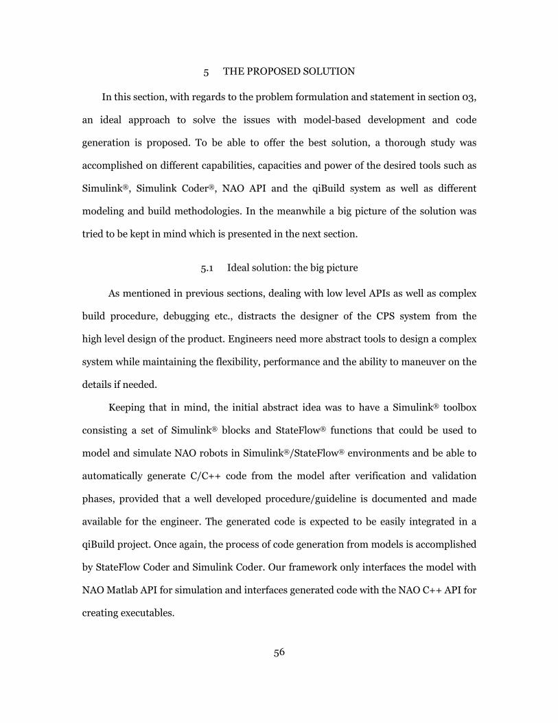
56
5 THE PROPOSED SOLUTION
In this section, with regards to the problem formulation and statement in section 03,
an ideal approach to solve the issues with model-based development and code
generation is proposed. To be able to offer the best solution, a thorough study was
accomplished on different capabilities, capacities and power of the desired tools such as
Simulink®, Simulink Coder®, NAO API and the qiBuild system as well as different
modeling and build methodologies. In the meanwhile a big picture of the solution was
tried to be kept in mind which is presented in the next section.
5.1 Ideal solution: the big picture
As mentioned in previous sections, dealing with low level APIs as well as complex
build procedure, debugging etc., distracts the designer of the CPS system from the
high level design of the product. Engineers need more abstract tools to design a complex
system while maintaining the flexibility, performance and the ability to maneuver on the
details if needed.
Keeping that in mind, the initial abstract idea was to have a Simulink® toolbox
consisting a set of Simulink® blocks and StateFlow® functions that could be used to
model and simulate NAO robots in Simulink®/StateFlow® environments and be able to
automatically generate C/C++ code from the model after verification and validation
phases, provided that a well developed procedure/guideline is documented and made
available for the engineer. The generated code is expected to be easily integrated in a
qiBuild project. Once again, the process of code generation from models is accomplished
by StateFlow Coder and Simulink Coder. Our framework only interfaces the model with
NAO Matlab API for simulation and interfaces generated code with the NAO C++ API for
creating executables.
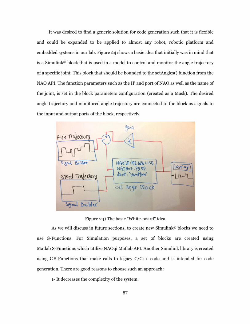
It was desired to find a generic solution for code
and could be expanded to
embedded systems in our lab.
is a Simulink® block that is used in a model to control and monitor the angle trajectory
of a specific joint. This block that should be bounded to the setAngles() function from the
NAO API. The function parameters such as the IP and port of NAO as well as the name of
the joint, is set in the block parameters configuration (created as a Mask). The desired
angle trajectory and monitored angle trajectory are connected to the block as signals to
the input and output ports of the block, respectively.
Figure
As we will discuss in future sections
use S-Functions. For Simulation purposes, a set of blocks are created using
Matlab S-Functions which utilize NAOqi Matlab API. Another Simulink library is created
using C S-Functions that make calls to legacy C/C++ code and is intended for code
generation. There are good reasons to choose such
1- It decreases the complexity of the system
57
to find a generic solution for code generation such that
to be applied to almost any robot, robotic platform
embedded systems in our lab. Figure 24 shows a basic idea that initially was in mind
block that is used in a model to control and monitor the angle trajectory
of a specific joint. This block that should be bounded to the setAngles() function from the
parameters such as the IP and port of NAO as well as the name of
the joint, is set in the block parameters configuration (created as a Mask). The desired
angle trajectory and monitored angle trajectory are connected to the block as signals to
d output ports of the block, respectively.
Figure 24) The basic "White-board" idea
in future sections, to create new Simulink® blocks we need
Functions. For Simulation purposes, a set of blocks are created using
which utilize NAOqi Matlab API. Another Simulink library is created
Functions that make calls to legacy C/C++ code and is intended for code
reasons to choose such an approach:
the complexity of the system.
such that it is flexible
platform and
shows a basic idea that initially was in mind that
block that is used in a model to control and monitor the angle trajectory
of a specific joint. This block that should be bounded to the setAngles() function from the
parameters such as the IP and port of NAO as well as the name of
the joint, is set in the block parameters configuration (created as a Mask). The desired
angle trajectory and monitored angle trajectory are connected to the block as signals to
blocks we need to
Functions. For Simulation purposes, a set of blocks are created using
which utilize NAOqi Matlab API. Another Simulink library is created
Functions that make calls to legacy C/C++ code and is intended for code
58
2- It reduces the issues with connecting MathWorks® Coder products and our
actual development build system (qiBuild).
3- You can add constructs such as “Try/Catch” for exception handling in your
legacy code. Some programming constructs such as try/catch are not basically supported
for code generation if used inside Matlab code.
4- This approach was desired to be a generic solution and could be applied to
many different robots, API, platforms, build systems, robotic frameworks (e.g. ROS).
5- This strategy hides the version incompatibility of the NAOqi API. For example
for moving NAO, before version 14, the function was named walkTo() and after that it
was renamed to moveTo(). We use the newer version as the unique interface in both
StateFlow Interface API, Simulink S-Functions and the C Interface API while underlying
code uses the most recent version of the API.
5.1.1 Ideal procedure
In the next paragraphs a procedure is presented that should be followed step by
step to create model-based NAO applications using our proposed framework.
The first step is to create the Simulink® model using the native blocks as well as
the proposed NAO Simulink® library for simulation. We also insert StateFlow charts
and use the StateFlow interface API to make functions calls such as “getAngles()”either
during transitions or inside states. Since both Simulink® block and the StateFlow®
interface API use the NAOqi Matlab API, we can start the simulation without any further
steps.
After we are satisfied with the simulation results we replace the NAO Simulink
library for simulation with its equivalent for code generation which includes
S-Functions utilizing the C/C++ interface API. To simplify the process, a configuration
file is provided for the users which should be imported to the model as its configuration

59
parameters setting. This file determines the basic configuration of the model such as the
type of solvers used or the properties of the generated code. It also specifies the legacy
interface header files to be included in the generated code as well as the “defines” that
are necessary for the application to run properly. One of the most important definitions
is the name mapping of robot addresses for facilitating the function call usage as shown
below. An example of the C interface function call is also presented. This address string
contains the IP and Port of the NAO. Interface API parses this string and extracts the IP
and port values automatically.
#define NAO_A “192.168.1.155:9559”
setAngles(NAO_A, “HeadYaw”, 1.2, 0.2);
Using Simulink Coder®, C/C++ code is generated for the whole model which in
part includes generated code for each single block that in turn incorporate interface API
function calls. Using PackNgo utility of Simulink coder, all the generated code, header
files and necessary Simulink files are packaged in one compressed file that makes the
transition to the qiBuild project easier. The generated code has one main file which
corresponds to the whole model and using three functions, Model_Initialize(),
Model_Step() and Model_Terminate() makes call to the associated functions of all the
blocks inside the model. There are other C/C++ files as well that each represents the
equivalent code for each block. We should note that due to the modularity feature of the
system we have defined all the custom blocks of our Simulink® library and also
StateFlow chart blocks as “Atomic reusable units” in the models and that is why for each
block a separate reusable function/file is generated.
The next step is the creation of the NAOqi project using the qiBuild system. After
initializing the project, a Microsoft Visual Studio® solution is also created which could be
used to develop the rest of the project in.

60
The final step would be the compilation. Since the Miscorosft Visual Studio®
solution is generated using the qiBuild system, all the linking to the compiler and make
system is taken care of so we can compile, run and debug the qiBuild project, which now
includes the model’s generated code, directly from Visual Studio. The resulting
executable could be executed from desktop machine and communicate with NAOqi
system running inside NAO via a Wi-Fi connection. Note that we can also generate code
and executable to be run on the NAO as a standalone module. The only change would be
to choose the cross-compile toolchain for Atom processors when creating the qiBuild
project.
61
5.2 Design consideration
Based on problem statement in section 3 it was established that a good solution
has to posses the following features to be accepted and utilized by control and software
engineers [56]:
5.2.1 High level
One of the core objectives of this thesis is to provide non-programmer engineers
with a high level tool that abstracts the functionality of NAO robots and is easy to
understand and model. While resembling a procedural programming interface it should
hold properties of a simulation environment.
5.2.2 Encapsulation
The blocks and intermediate functions/classes used in modeling and code
generation process should encapsulate the details of the system so the engineer is not
concerned about the details such as library dependencies or run-time error handling.
5.2.3 Layered Architecture
A good design principle in computer systems development is layered
architecture. This has been practiced in many standards such as ISO OSI reference mode
for networking and is proved to be valuable. In [57] and [58] author (Rodney Brooks,
founder of iRobot Corporation), has proposed a layered architecture for mobile robot
design and shows how to decompose a complex design problem using this type of
architecture. In the later publication, reusability of such design practice for different
targets is emphasized.
5.2.4 Reusable
Our proposed framework had to be modular and reusable so that the procedure
could be used in various situations. This constraint also contributes to the encapsulation

62
and high level features described before. An effort has been made to create all Simulink®
blocks, functions and also the interface C/C++ API to be reusable and modular such that
high-level models and low-level components could be reused.
5.2.5 Flexible
Even though the framework and examples in this work are based on a specific
operating system, particular build system and modeling software and a specific type of
robots (NAO Humanoids), the utmost effort has been made to provide the procedures
and guidelines as generic as possible such that high-level software models can be reused
on other low-level platforms that offer a similar set of APIs.
5.2.6 Expandable
All software, APIs and robotic systems used in this thesis are academic but
complex and full-featured products. The proposed framework is created to be used as
more of a “template” so that the rest of the system’s capacity could be integrated and
utilized as a part of the framework without a hassle.
5.2.7 Hierarchical design
Hierarchical design helps engineers to cope with complexity of the systems. If a
bottom-up design approach is taken, the designer of the system starts by developing
smaller systems. After verifying the functionality and testing, they could be used as the
atomic building blocks or components of the higher level hierarchy. In top-down
approach, first a big picture of the highest level system with the desired I/O and
computational functionality is designed and then the designer steps inside the top levels
system and starts designing the lower levels. In [59], [60], and [61] in separate
researches, authors have designed hierarchical controls systems for Unmanned Aerial
vehicles (UAV) emphasizing the importance of hierarchical approach.
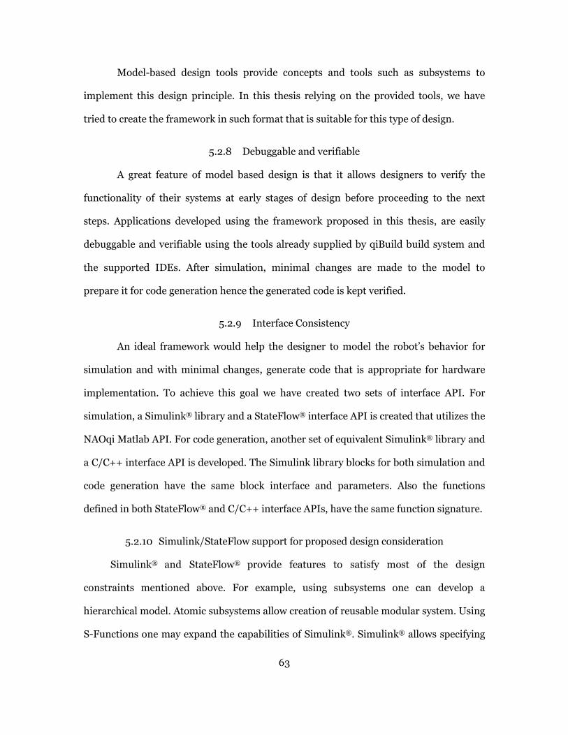
63
Model-based design tools provide concepts and tools such as subsystems to
implement this design principle. In this thesis relying on the provided tools, we have
tried to create the framework in such format that is suitable for this type of design.
5.2.8 Debuggable and verifiable
A great feature of model based design is that it allows designers to verify the
functionality of their systems at early stages of design before proceeding to the next
steps. Applications developed using the framework proposed in this thesis, are easily
debuggable and verifiable using the tools already supplied by qiBuild build system and
the supported IDEs. After simulation, minimal changes are made to the model to
prepare it for code generation hence the generated code is kept verified.
5.2.9 Interface Consistency
An ideal framework would help the designer to model the robot’s behavior for
simulation and with minimal changes, generate code that is appropriate for hardware
implementation. To achieve this goal we have created two sets of interface API. For
simulation, a Simulink® library and a StateFlow® interface API is created that utilizes the
NAOqi Matlab API. For code generation, another set of equivalent Simulink® library and
a C/C++ interface API is developed. The Simulink library blocks for both simulation and
code generation have the same block interface and parameters. Also the functions
defined in both StateFlow® and C/C++ interface APIs, have the same function signature.
5.2.10 Simulink/StateFlow support for proposed design consideration
Simulink® and StateFlow® provide features to satisfy most of the design
constraints mentioned above. For example, using subsystems one can develop a
hierarchical model. Atomic subsystems allow creation of reusable modular system. Using
S-Functions one may expand the capabilities of Simulink®. Simulink® allows specifying

64
two different set of legacy code for integrating with the model; one set for simulation and
another one for code generation. Using this feature the engineer can develop one
interface for two implementations. Finally Simulink® offers a great built-in debugging
utility as well as model checking tools.
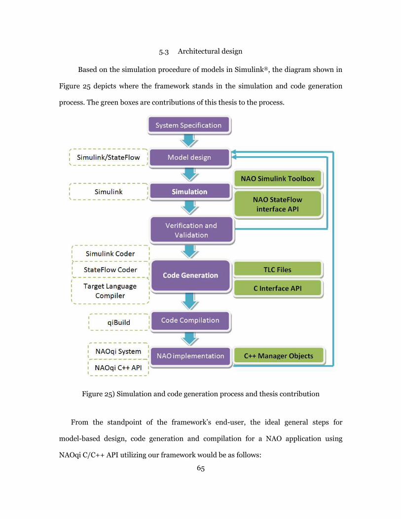
65
5.3 Architectural design
Based on the simulation procedure of models in Simulink®, the diagram shown in
Figure 25 depicts where the framework stands in the simulation and code generation
process. The green boxes are contributions of this thesis to the process.
Figure 25) Simulation and code generation process and thesis contribution
From the standpoint of the framework’s end-user, the ideal general steps for
model-based design, code generation and compilation for a NAO application using
NAOqi C/C++ API utilizing our framework would be as follows:

66
1. Creating a qiBuild project
2. Initializing and building the project
3. Developing Simulink model and StateFlow charts using NAO Simulink® toolbox
and StateFlow® Interface API
4. Configuring the model configuration parameter for code generation
5. Generating code from the model
6. Integrating the generated code with existing qiBuild project in an IDE
7. Compiling and building the project using qiBuild system through the IDE
8. Testing and verifying the conformance of the application with the model
9. Iterating the process from step 3 if the desired results are not achieved
To fully utilize the code generation tools of MathWorks® products, it is necessary to
add some extensions to the current system to enhance its capabilities. Based on the
accomplished literature review and studying the Coder products’ documentations, it was
established that we need to add the following modules to the system.
• A StateFlow Interface API for simulation (utilizing NAOqi Matlab API)
• A NAO Simulink Library for Simulation (using M-S-Functions utilizing NAOqi
Matlab API)
• A NAO Simulink Library for code generation (using C-S-Functions utilizing
NAOqi C++ API)
• A set of Target Language Compiler files
• C/C++ Interface API including implementing and wrapping NAO C++ API
• A default configuration file to be used for the models
The characteristic and architecture of these tools are explained in the following sections.

67
5.3.1 Framework Architecture
Based on the design considerations, the architecture shown in Figure 28 was
proposed. In this layered architecture, some components are off-the-shelf such as
Simulink®, Simulink Coder® and NAOqi API and some are designed and developed as a
part of our framework such as the StateFlow Interface API and C/C++ Interface API.
After developing the model, if user decides to simulate it, he/she proceeds with
the StateFlow® Interface API and Simulink® toolbox created for simulation. For code
generation, user simply replaces simulation toolbox and interface API with the
Simulink® toolbox and C/C++ interface API developed for code generation. Minimal or
no changes are made to the actual algorithm in the model. Figure 26 and Figure 27
demonstrate the high level architecture used to develop our framework. The top blue
layer us what is developed by the end-users of our framework, the middle green layer
shows our contribution and bottom purple section shows already available tools and
software.

68
Figure 26) High level architecture for frameworks usage for Simulink model

69
Figure 27) High level architecture for frameworks usage for StateFlow Charts

70
Figure 28) Framework architecture

71
5.3.2 NAO Simulink® Library
Using NAOqi framework APIs, a Simulink® toolbox containing Simulink blocks is
created that uses “Legacy Code Integration” features of Simulink Coder®. It is composed
of interfaces to the classes and functions of the API.
This block set includes NAO Initialization Blocks, NAO Motion Blocks, NAO
Vision Blocks and NAO Speech Blocks. The blocks are created in different levels of
abstractions. For example there are blocks for changing the angle of a joint (as a low level
functionality) as well as blocks for walking (which uses walking algorithms developed for
NAO). Development these blocks are based on the Simulink C-MEX S-functions which
are appropriate for code generation. S-Function Builder is used to create these blocks.
5.3.3 Target Language Compiler (TLC) files
Simulink Coder to be able to generate correct code and integrate legacy C code
into our models and the generated code, needs know about the functionality and how to
map each block to C/C++ code. This is performed by creating custom TLC files to be
used by the Target Language Compiler in code generation process. S-Function Builder
tool assists in automatic generation of these files however some modification of the
structure of these files was inevitable.
5.3.4 Interface Wrapper Classes and Functions
As mentioned before, one of the good approaches for code generation for custom
target systems is to provide higher level abstractions for the available functionalities as
well as creating higher level function wrappers to be used in models that will eventually
call the legacy API functions in compilation process.
Simulink allows users to integrate two sets of legacy code in their models and
blocks: one set for simulation purposes and one set for code generation as indicated in
Figure 29.

72
Figure 29) specifying separate integrated code for simulation and code generation purposes
The details of implementation are fully explained in section 5.4.
5.3.5 Default configuration file
All aspects of the model’s configuration could be defined and modified using the
“Model Configuration Parameter” panel. One can modify and tune these parameters to
achieve the desired results both in simulation and code generation. A model
configuration could be exported as an M-File and later used in future developments by
importing it.
After performing many tests and adjustments, a final configuration file was
determined to be the most suitable for use in our proposed framework. This
configuration also includes custom code directives, library paths, source codes, “include
files” and directories to be integrated in the generated code.
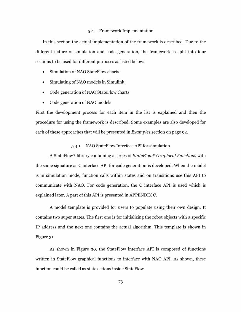
73
5.4 Framework Implementation
In this section the actual implementation of the framework is described. Due to the
different nature of simulation and code generation, the framework is split into four
sections to be used for different purposes as listed below:
• Simulation of NAO StateFlow charts
• Simulating of NAO models in Simulink
• Code generation of NAO StateFlow charts
• Code generation of NAO models
First the development process for each item in the list is explained and then the
procedure for using the framework is described. Some examples are also developed for
each of these approaches that will be presented in Examples section on page 92.
5.4.1 NAO StateFlow Interface API for simulation
A StateFlow® library containing a series of StateFlow® Graphical Functions with
the same signature as C interface API for code generation is developed. When the model
is in simulation mode, function calls within states and on transitions use this API to
communicate with NAO. For code generation, the C interface API is used which is
explained later. A part of this API is presented in APPENDIX C.
A model template is provided for users to populate using their own design. It
contains two super states. The first one is for initializing the robot objects with a specific
IP address and the next one contains the actual algorithm. This template is shown in
Figure 31.
As shown in Figure 30, the StateFlow interface API is composed of functions
written in StateFlow graphical functions to interface with NAO API. As shown, these
function could be called as state actions inside StateFlow.
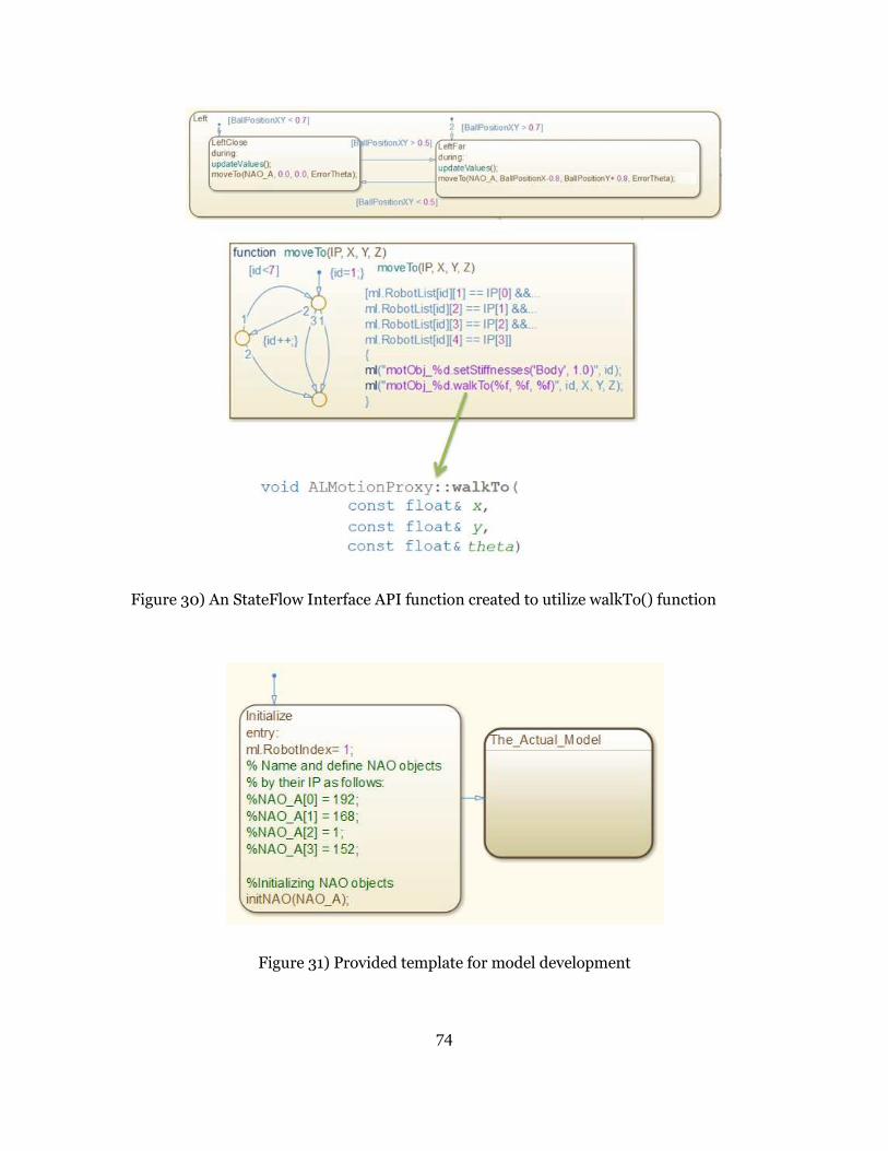
74
Figure 30) An StateFlow Interface API function created to utilize walkTo() function
Figure 31) Provided template for model development

75
In StateFlow, you can call a Matlab function as your action using the “ml”
namespace or ml() function. Using this function, we can call the Matlab® API functions
as we use them in Matlab® environment. The point is that since we are calling a Matlab®
function, we should assign the return values of functions to a Matlab® variable or object.
We can access Matlab environment variables using the following syntax:
ml.theVar
The approach that is taken for resolving run-time errors and catching exceptions
should have been declared. For example when the ALMotionProxy cannot connect and
create a function, an exception is thrown by the NAO API. One way is to use try and
catch in a Matlab script. However you cannot use try/catch construct inside states as
actions.
Before one starts to develop the algorithm in the model, they need to create robot
objects using their IP addresses. The function initNAO(NAO_IP) from the StateFlow
Interface API should be called in the first super state, passing an IP address as an array
of 4 integers. Due to the limitations of StateFlow® for using strings, it is not possible to
use a string for the IP addresses. The necessary objects will be created and placed inside
a list called RobotList[]. When a function is called within a state or on transitions, the list
is searched for the object with the specific IP and it calls the method on that object. Note
that for code generation there is no need to add these initial states since the object
creation and management is taken care of inside the C/C++ interface API.
Figure 32 shows the initNAO(IP[]) function used to create objects of three sample
NAOqi classes of one NAO and adding them to RobotList array.
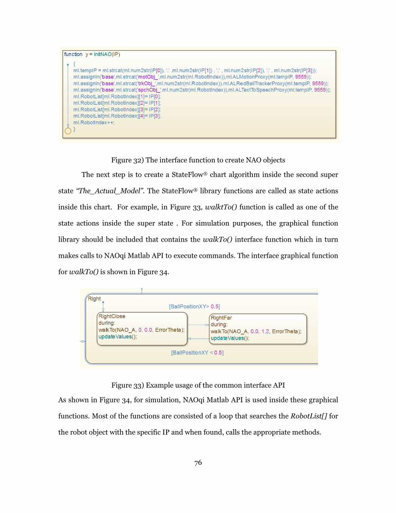
76
Figure 32) The interface function to create NAO objects
The next step is to create a StateFlow® chart algorithm inside the second super
state “The_Actual_Model”. The StateFlow® library functions are called as state actions
inside this chart. For example, in Figure 33, walktTo() function is called as one of the
state actions inside the super state . For simulation purposes, the graphical function
library should be included that contains the walkTo() interface function which in turn
makes calls to NAOqi Matlab API to execute commands. The interface graphical function
for walkTo() is shown in Figure 34.
Figure 33) Example usage of the common interface API
As shown in Figure 34, for simulation, NAOqi Matlab API is used inside these graphical
functions. Most of the functions are consisted of a loop that searches the RobotList[] for
the robot object with the specific IP and when found, calls the appropriate methods.

77
Figure 34) An example of a StateFlow interface API function
5.4.1.1 Time-based modeling
StateFlow chart execution is bounded to the execution of the parent
model. The timing constraints defined for the top level model such as step size is
also applied to the StateFlow chart. So in each simulation time step, the chart’s
internal states and outputs are calculated, state transitions are made and possible
state actions are executed. For example if you define a state action using “entry”
keyword, the NAO task will be executed once and if you call it inside a “during”, it
keeps executing in every time step.
Regarding delays, first of all, since a “call” is made to NAO native APIs to
perform a task and we are not using a multi-threaded structure here, the
simulation (as well as remote execution from within Simulink) is paused till the
execution is complete and then it moves to the next simulation step. To add more
timing constraints you can use StateFlow temporal operators such as “after”. All
these timings will be automatically considered and converted to the C/C++ code
by Simulink coder. No specific timing is utilized in our framework in the interface
APIs.

78
5.4.1.2 Event based modeling
StateFlow charts support event-based modeling. Our framework also
supports this feature. Using NAO Simulink toolbox, you can add blocks to your
model for reading sensor values or polling event signals from NAO. The outputs
of these blocks could be used as the events triggering a transition inside the
StateFlow chart. Of course you need to define the input as an event signal to the
state chart.
Regarding generating events, other than event generated inside StateFlow
as a part of your design, you can use the output of StateFlow interface functions
to create event signals for output. You can also subscribe to some events
produced using the NAOqi API. For example, you may subscribe to the
BatteryFullChargedFlagChanged event from ALBattery API:
callback(std::string eventName, bool fullyCharged, string subscriberIdentifier)
This event is raised when the “battery fully charged” changes and the callback
function is executed. You may use the callback functions inside your StateFlow
charts as well. Of course you first need to subscribe to this event to be notified
when it’s raised. Figure 36 and Figure 37 show the usage of events in an example.

79
Figure 35) Example model; block generating an event used in a StateFlow chart
Figure 36) Using the input event

80
5.4.2 StateFlow® Code generation
After creating and simulating the model using the StateFlow® interface API, in
order to proceed with code generation the only necessary action would be to remove the
StateFlow® library and import the specification for legacy C/C++ interface API in the
model’s configuration parameters.
The interface API is split into two sections. A pure C interface API that is
accessible through Simulink® S-Functions as well as by StateFlow® charts and the next
layer is the C++ Manager classes that take care of object creation and management. The
C interface API functions act as “wrappers” for the creation of appropriate objects from
NAOqi classes and making calls to their methods. The C Interface API has the same
signature as the StateFlow Interface API so that no change would be necessary in the
StateFlow® chart when transiting from simulation to code generation.
To be able to use the created interface wrapper class in StateFlow®, there is no
choice similar to creating S-Functions in Simulink. For implementing a StateFlow® chart
in a Simulink model, one has four options as shown in Figure 37.
Figure 37) StateFlow toolbox
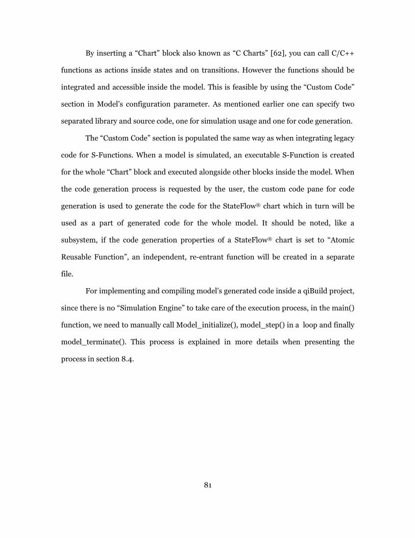
81
By inserting a “Chart” block also known as “C Charts” [62], you can call C/C++
functions as actions inside states and on transitions. However the functions should be
integrated and accessible inside the model. This is feasible by using the “Custom Code”
section in Model’s configuration parameter. As mentioned earlier one can specify two
separated library and source code, one for simulation usage and one for code generation.
The “Custom Code” section is populated the same way as when integrating legacy
code for S-Functions. When a model is simulated, an executable S-Function is created
for the whole “Chart” block and executed alongside other blocks inside the model. When
the code generation process is requested by the user, the custom code pane for code
generation is used to generate the code for the StateFlow® chart which in turn will be
used as a part of generated code for the whole model. It should be noted, like a
subsystem, if the code generation properties of a StateFlow® chart is set to “Atomic
Reusable Function”, an independent, re-entrant function will be created in a separate
file.
For implementing and compiling model’s generated code inside a qiBuild project,
since there is no “Simulation Engine” to take care of the execution process, in the main()
function, we need to manually call Model_initialize(), model_step() in a loop and finally
model_terminate(). This process is explained in more details when presenting the
process in section 8.4.
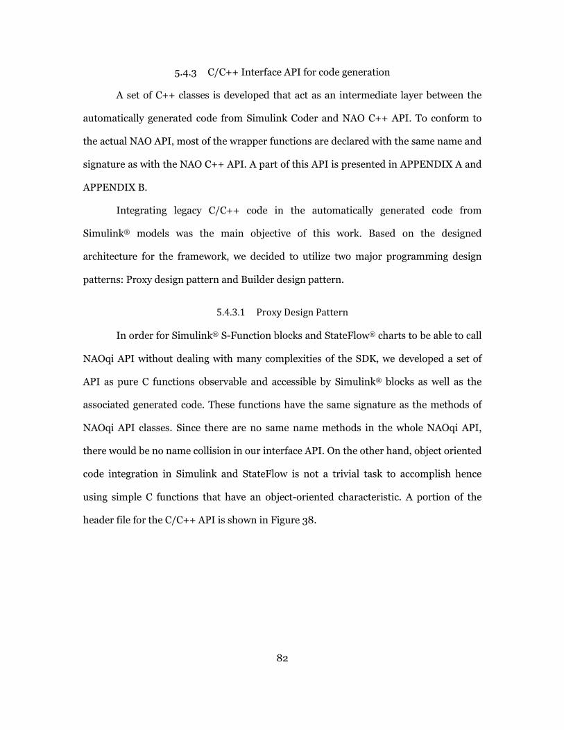
82
5.4.3 C/C++ Interface API for code generation
A set of C++ classes is developed that act as an intermediate layer between the
automatically generated code from Simulink Coder and NAO C++ API. To conform to
the actual NAO API, most of the wrapper functions are declared with the same name and
signature as with the NAO C++ API. A part of this API is presented in APPENDIX A and
APPENDIX B.
Integrating legacy C/C++ code in the automatically generated code from
Simulink® models was the main objective of this work. Based on the designed
architecture for the framework, we decided to utilize two major programming design
patterns: Proxy design pattern and Builder design pattern.
5.4.3.1 Proxy Design Pattern
In order for Simulink® S-Function blocks and StateFlow® charts to be able to call
NAOqi API without dealing with many complexities of the SDK, we developed a set of
API as pure C functions observable and accessible by Simulink® blocks as well as the
associated generated code. These functions have the same signature as the methods of
NAOqi API classes. Since there are no same name methods in the whole NAOqi API,
there would be no name collision in our interface API. On the other hand, object oriented
code integration in Simulink and StateFlow is not a trivial task to accomplish hence
using simple C functions that have an object-oriented characteristic. A portion of the
header file for the C/C++ API is shown in Figure 38.
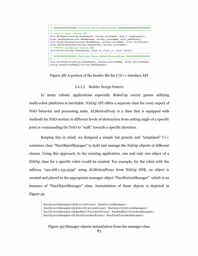
83
Figure 38) A portion of the header file for C/C++ interface API
5.4.3.2 Builder Design Pattern
In many robotic applications especially RoboCup soccer games utilizing
multi-robot platforms is inevitable. NAOqi API offers a separate class for every aspect of
NAO behavior and processing tasks. ALMotionProxy is a class that is equipped with
methods for NAO motion in different levels of abstraction from setting angle of a specific
joint or commanding the NAO to “walk” towards a specific direction.
Keeping this in mind, we designed a simple but generic and “templated” C++
container class “NaoObjectManager” to hold and manage the NAOqi objects of different
classes. Using this approach, in the running application, one and only one object of a
NAOqi class for a specific robot would be created. For example, for the robot with the
address “192.168.1.155:9559” using ALMotionProxy from NAOqi SDK, an object is
created and placed in the appropriate manager object “NaoMotionManager” which is an
instance of “NaoObjectManager” class. Instantiation of these objects is depicted in
Figure 39.
Figure 39) Manager objects instantiation from the manager class

84
Having these manager objects handy, a call to the C interface API functions from
the model, searches for a the associated robot object in the list, creates one instance if the
object is not already created, adds it to the list and uses that NAOqi object by calling its
standard methods.
Note that developed models from Simulink and StateFlow have no knowledge
about the existence of actual NAOqi API and only interact with our framework’s classes
and functions. Relying on manager objects, our framework also supports modeling and
code generation for multi-robot NAO systems as well as single robot models.
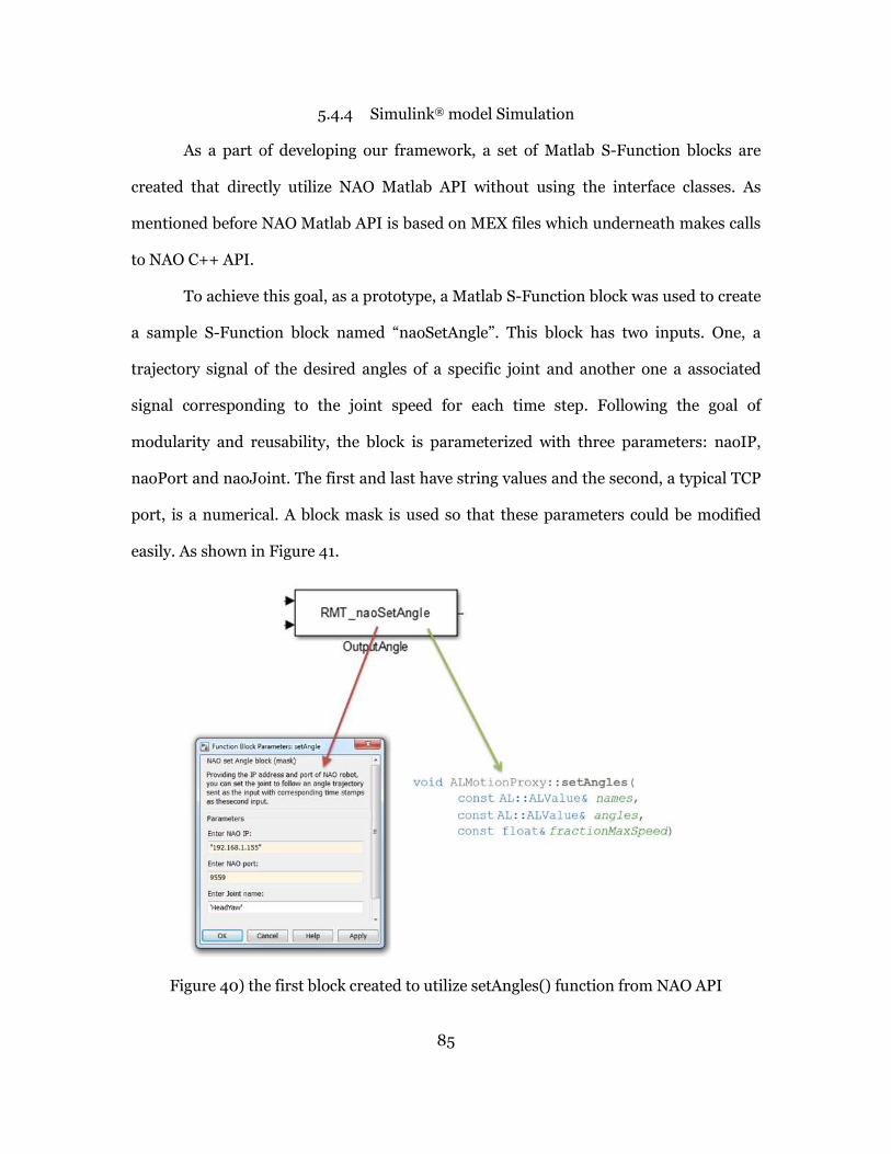
85
5.4.4 Simulink® model Simulation
As a part of developing our framework, a set of Matlab S-Function blocks are
created that directly utilize NAO Matlab API without using the interface classes. As
mentioned before NAO Matlab API is based on MEX files which underneath makes calls
to NAO C++ API.
To achieve this goal, as a prototype, a Matlab S-Function block was used to create
a sample S-Function block named “naoSetAngle”. This block has two inputs. One, a
trajectory signal of the desired angles of a specific joint and another one a associated
signal corresponding to the joint speed for each time step. Following the goal of
modularity and reusability, the block is parameterized with three parameters: naoIP,
naoPort and naoJoint. The first and last have string values and the second, a typical TCP
port, is a numerical. A block mask is used so that these parameters could be modified
easily. As shown in Figure 41.
Figure 40) the first block created to utilize setAngles() function from NAO API
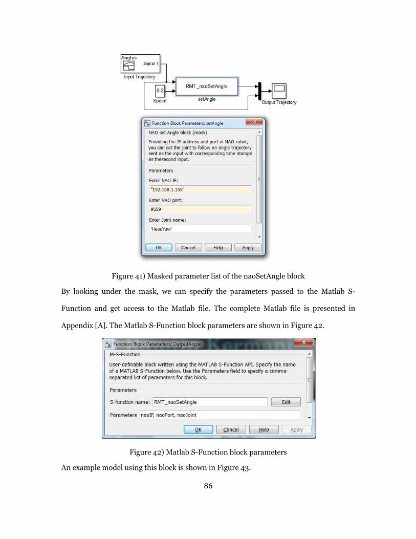
86
Figure 41) Masked parameter list of the naoSetAngle block
By looking under the mask, we can specify the parameters passed to the Matlab S-
Function and get access to the Matlab file. The complete Matlab file is presented in
Appendix [A]. The Matlab S-Function block parameters are shown in Figure 42.
Figure 42) Matlab S-Function block parameters
An example model using this block is shown in Figure 43.

87
Figure 43) Example usage of the naoSetAngle block in a model
The desired and actual trajectory signals have a very small error as depicted in Figure 44.
Figure 44) Simulation result for the model utilizing naoSetAngle block
Because this type of blocks (Matlab S-Functions) are using the NAO Matlab API
which in turn uses a pre-compiled MEX function, we cannot generate code for this
models and are only good for simulation and remote control of the robot from
simulation. As shown in the following sections, we have overcome this issue by using the
NAO C++ API and creating C-MEX S-Functions implementing legacy code that are
suitable for code generation as well.

88
5.4.5 Simulink model-based code generation
In section 5.4.3 the interface wrapper classes were introduced. Those classes are
used as an interface between the automatically generated code from the model and the
NAO C++ API.
In this section we illustrate how to create our Simulink blocks for inclusion in the
framework’s library and show an example usage and the code generation process in later
sections.
As explained in section 4.2.6.3, S-Functions are a good approach to enhance the
capabilities of Simulink® as well as integrating legacy C/C++ code into our models and it
was mentioned that there are a couple of ways to create a Simulink S Function blocks.
For this framework, S-Function Builder [42] is used to develop necessary
Simulink library blocks. Creating S-Function blocks using S-Function Builder is very
easy and the automatically generated blocks are suitable for both simulation as well as
code generation. Using S-Functions we create blocks that implement our interface
wrapper code (explained in section 5.4.1). The following figures show the process of
creating the S-Function block using the S-Function builder for setAngles() function.
Note that for simulation, we should use the Matlab S-Fucntion block and for code
generation use these blocks instead. We do not compile the S-Functions here. These
blocks are in fact place holders that call C Interface API in the generated code.

89
Figure 45) configuring the I/O of the S-Fnction block
Figure 46) the function call to the C Interface API is performed in the 'Output' section
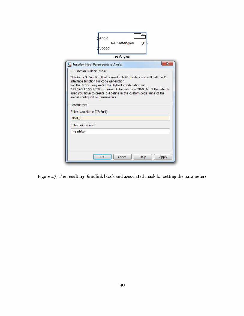
90
Figure 47) The resulting Simulink block and associated mask for setting the parameters
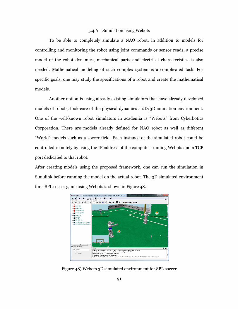
91
5.4.6 Simulation using Webots
To be able to completely simulate a NAO robot, in addition to models for
controlling and monitoring the robot using joint commands or sensor reads, a precise
model of the robot dynamics, mechanical parts and electrical characteristics is also
needed. Mathematical modeling of such complex system is a complicated task. For
specific goals, one may study the specifications of a robot and create the mathematical
models.
Another option is using already existing simulators that have already developed
models of robots, took care of the physical dynamics a 2D/3D animation environment.
One of the well-known robot simulators in academia is “Webots” from Cyberbotics
Corporation. There are models already defined for NAO robot as well as different
“World” models such as a soccer field. Each instance of the simulated robot could be
controlled remotely by using the IP address of the computer running Webots and a TCP
port dedicated to that robot.
After creating models using the proposed framework, one can run the simulation in
Simulink before running the model on the actual robot. The 3D simulated environment
for a SPL soccer game using Webots is shown in Figure 48.
Figure 48) Webots 3D simulated environment for SPL soccer

92
6 EXAMPLES
In this section two behavioral scenarios are defined for NAO and are developed
using traditional tools as well as the Framework proposed in previous sections. The goal
is to achieve an overall experience about the functionality and power of our framework
by comparing it with the conventional methods of programming NAO. We also would
investigate and make sure all the desired properties listed in section 5.2 are incorporate
into out Framework design.
The main objective of providing this framework is to facilitate the process of robot
application development as well as the usage of the off-the-shelf algorithms such as
Simulink® toolboxes for vision and control. To demonstrate the benefits offered by this
framework, we developed two applications, one a low level joint control and the other a
high level behavioral task. Both were implemented using traditional coding method and
also using model-based design and our framework.
First example was a simple PI control algorithm for controlling the HeadYaw joint
of NAO. We used the custom Simulink® block to utilize the setAngles() function to set
the angle of the HeadYaw joint and getAngles() to provide a feedback from the actual
angle of the joint. A simple PI controller is used to compensate for the error.
For the second example, which emphasized on the high-level logic of NAO’s
behavior, a StateFlow® chart was developed. We activated the RedBallTracker module
within NAO that makes the robot look for a red ball by turning its head and follow the
red ball. Based on the angle values read and the current position of the ball, NAO moves
its body towards the ball and if the ball is farther than a specific distance, it starts
walking towards it.
In both examples, model-based design as promised helped us focus on the
development of the algorithm and feedback control as well as the high level logic instead

93
of dealing with NAOqi class instantiation, exception handling, etc. Integration process
from generated code to the qiBuild project was comparatively longer compared to the
hand coding. However, this extra time is almost fixed and in larger projects will be
negligible compared to the time that model-based design saves us. Figure 49 and Figure
50 show the top level Simulink® model and the StateFlow® chart, respectively.
Figure 49) The Simulink model for following the ball

94
Figure 50) The StateFlow model for following the red ball
Figure 51) The initialization super state of the StateFlow chart and the actual super state containing the chart of Figure 50

95
7 CONCLUSIONS AND FUTURE WORK
In this thesis a framework along with a procedure for model-based design,
simulation and code generation for NAO robots is developed and presented. It was
shown that using model-based design we can benefit by saving time, preserving accuracy
and create validated and verified robot applications. The toolbox can be downloaded and
evaluated at
http://kermani.us/index.php/nao-mbd-toolbox
Beyond the benefits of utilizing state machines for the high level modeling of the
system behavior, now a range of verification and automatic synthesis tools become
accessible. Most importantly the system behavior can now be verified using tools like S-
TaLiRo [45], HyLink [63] , Simulink Design Verifier [64] and Polyspace [65].
The current approach would be to add blocks to the library on a “need-to” basis
since NAOqi API contains a very large set of classes and functions. One of the future
directions to continue this work would be to complete the Simulink® toolbox by adding
more blocks representing the rest of NAO API functionalities as well as the
corresponding C/C++ and StateFlow interface API.
One of the important design objectives of this framework is to provide a general
guideline and structure to be used for different types of robots and embedded systems.
Even though the implementation is focused on NAO robots, one can easily develop a
similar framework including the Simulink® library and interface C/C++ code that is
suitable for model-based design, simulation and code generation.
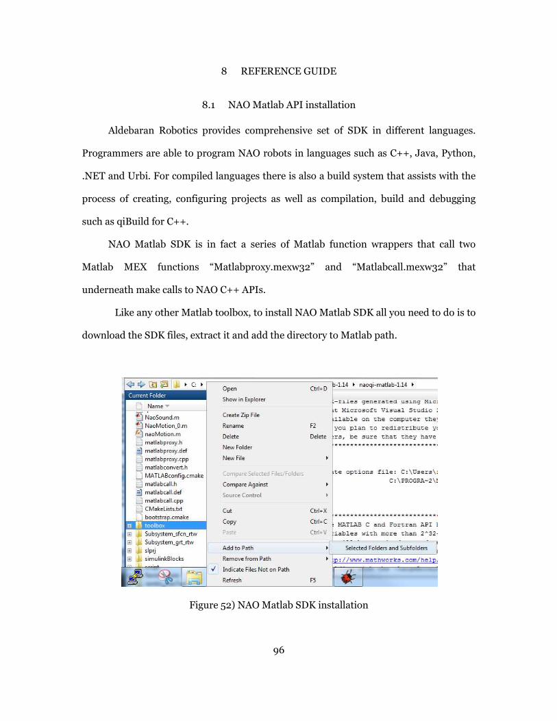
96
8 REFERENCE GUIDE
8.1 NAO Matlab API installation
Aldebaran Robotics provides comprehensive set of SDK in different languages.
Programmers are able to program NAO robots in languages such as C++, Java, Python,
.NET and Urbi. For compiled languages there is also a build system that assists with the
process of creating, configuring projects as well as compilation, build and debugging
such as qiBuild for C++.
NAO Matlab SDK is in fact a series of Matlab function wrappers that call two
Matlab MEX functions “Matlabproxy.mexw32” and “Matlabcall.mexw32” that
underneath make calls to NAO C++ APIs.
Like any other Matlab toolbox, to install NAO Matlab SDK all you need to do is to
download the SDK files, extract it and add the directory to Matlab path.
Figure 52) NAO Matlab SDK installation
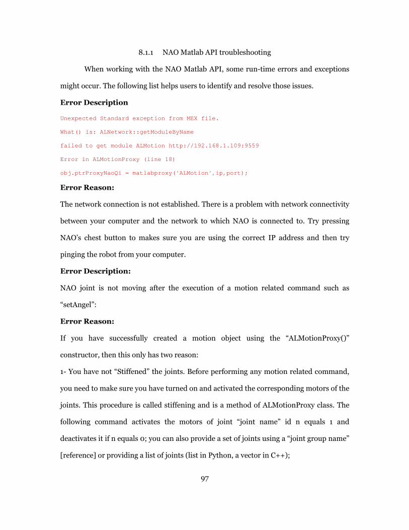
97
8.1.1 NAO Matlab API troubleshooting
When working with the NAO Matlab API, some run-time errors and exceptions
might occur. The following list helps users to identify and resolve those issues.
Error Description
Unexpected Standard exception from MEX file.
What() is: ALNetwork::getModuleByName
failed to get module ALMotion http://192.168.1.109: 9559
Error in ALMotionProxy (line 18)
obj.ptrProxyNaoQi = matlabproxy('ALMotion',ip,port) ;
Error Reason:
The network connection is not established. There is a problem with network connectivity
between your computer and the network to which NAO is connected to. Try pressing
NAO’s chest button to makes sure you are using the correct IP address and then try
pinging the robot from your computer.
Error Description:
NAO joint is not moving after the execution of a motion related command such as
“setAngel”:
Error Reason:
If you have successfully created a motion object using the “ALMotionProxy()”
constructor, then this only has two reason:
1- You have not “Stiffened” the joints. Before performing any motion related command,
you need to make sure you have turned on and activated the corresponding motors of the
joints. This procedure is called stiffening and is a method of ALMotionProxy class. The
following command activates the motors of joint “joint name” id n equals 1 and
deactivates it if n equals 0; you can also provide a set of joints using a “joint group name”
[reference] or providing a list of joints (list in Python, a vector in C++);

98
motionObj.setStifnesses(<joint name>, n)
2- You are setting the angle of a joint to its current angle which obviously wouldn’t make
it move.

99
8.2 QiBuild and SDK Installation
qiBuild is a build system by Aldebaran Robotics based on CMake that facilitates
creating cross-platform projects, compilation and build [66].
8.2.1 qiBuild Installation
• Install CMake from the website and modify the path to C:/CMake and when
prompted to add to PATH, say ok.
• Install Python 2.7+
• Download the C++ SDK from the DVD (naoqi-sdk-1.14.1-win32-vs2008.zip) and
copy it to a folder on your computer and unzip it. You can find it on the DVD
in Download > Software > SDK > NAOqi SDK > C++
• Also do the same for qibuild-1.14.1.zip. unzip it and run install-qibuild.bat, when
installation is complete you get the following message
Figure 53) Final stage of qiBuild installation
• Next you need to configure the qiBuild by entering:
> qibuild config --wizard
qiBuild finds the available IDEs and compilers on your system and asks to choose
one as depicted in Figure 54.

100
Figure 54) Configuring qiBuild
8.2.2 Creating a initializing a Work tree
A Work tree is a top level folder for creating all your NAO projects. A Work Tree
should be created, initialized and configured first. All new projects should be created
inside that directory so that it would be accessible by qiBuild.
To create a work tree and a project, go to your workspace directory and run:
> qibuild init
This command creates a work tree that you can add your projects under it. The result is a
folder names “.qi”.
For your whole working directory you only need to perform “qibuild init” once which will
cover all projects created inside that directory.

101
8.2.3 Creating a toolchain
As mentioned before, there are two SDK sets available for compiling NAO
applications, one for desktop remote applications (either in Windows, MAC or Linux)
and one for Atom processor to be run on the robot locally. A Toolchain is technically a
configuration that is hooked to a specific SDK and in compilation process by choosing a
toolchain, you implicitly choose which SDK to use.
The following line creates a toolchain named naoCPPtoolchain which points to
the SDK for desktop application running on Windows 32 bit.
> qitoolchain create naoCPPtoolchain C:\NAOqi\naoqi -sdk-1.14.1-win32- �
� vs2008\naoqi-sdk-1.14.1-win32-vs2008\toolchain.xml --default
8.2.4 Status of available toolchains
During work one might create multiple toolchains for different projects. It may
become confusing. Check the status of your available toolchains using the following
command. The result in Figure 55 shows the two available toolchains.
> qitoolchain info
Figure 55) checking available toolchains
8.2.5 Creating, configuring and building a new project
To create a new project in the current Work Tree, use the following command:
> qibuild create newProjectsName

102
To configure the project to use a specific toolchain, use the following command:
> qibuild configure -c NameOfTheToolchain Project Name
Note) you have to be at the same directory as “.qi” folder to be able to configure or make
a project, not inside the project folder.
At this point you should have the following project hierarchy:
You can simply open the main.cpp file, modify and compile it. To make and build a
project, execute the following command:
> qibuild make -c NameOfTheToolchain ProjectName
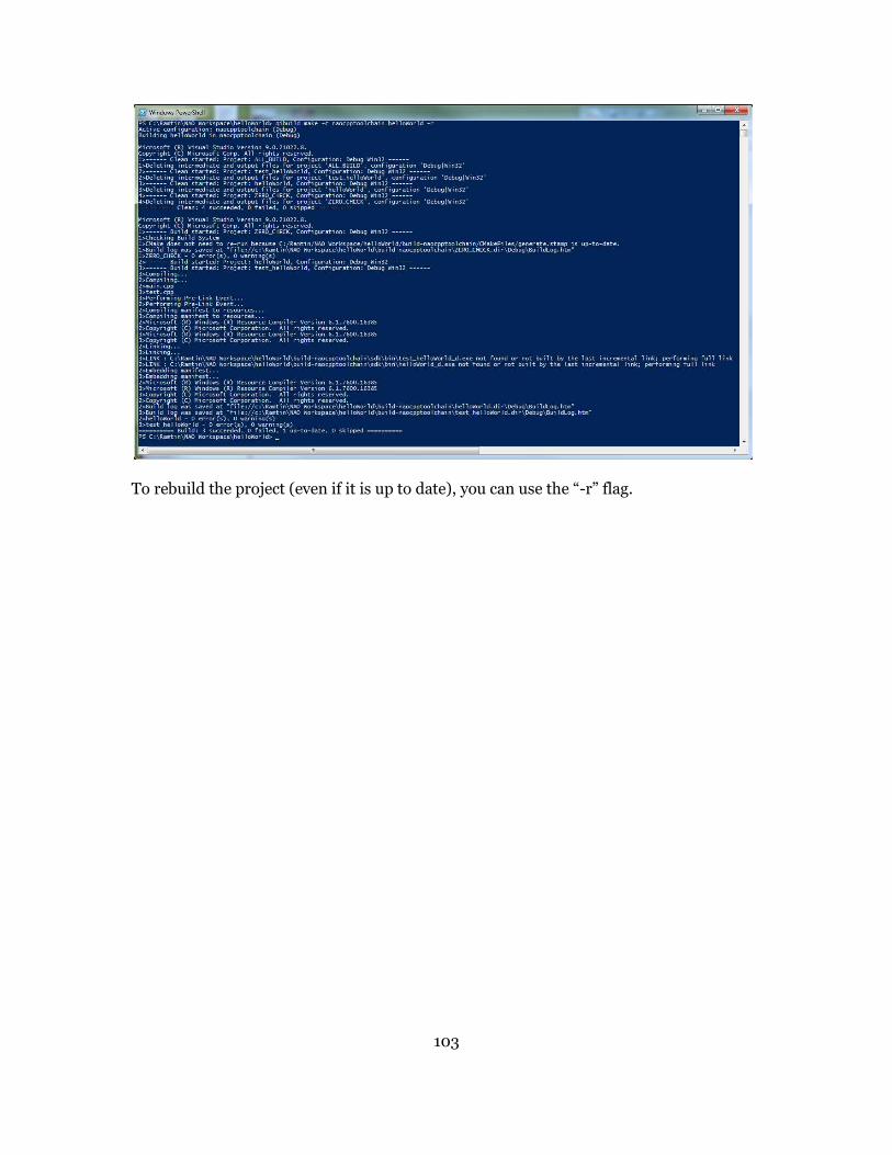
103
To rebuild the project (even if it is up to date), you can use the “-r” flag.

104
8.2.6 Using Microsoft Visual Studio to build the projects
Now if you check the projects directory you should notice that make files and
even a Visual Studio Solution file is created. That is because we chose “Visual Studio
2008” as our IDE and compiler. Now you can even open the solution in Visual Studio
and modify your code and run it there. As it will be explained in section 8.4, that is what
is needed to be done when we want to integrate the automatically generated code from
our Simulink models with our qiBuild project.
Figure 56) The file strcuture of qiBuild project after initial build
You can open the solution and simply use your designated IDE to write the code
and build it. In Figure 57, a qiBuild project is opened, built and run in Visual studio.
Note) When trying to run the project, after successful compilation, you need to
specify an executable name. Choose Browse and point to the following address (of course
if your project name is helloWorld):
“<NAOWorkspace>\helloWorld\build-naocpptoolchain\sd k\bin\helloWorld.exe”
105
Figure 57) Opening the qiBuild solution in VS and running it
Note) You can write and compile simple C/C++ applications at this point.
However if you want to use the NAO SDK, for example including a header file by using
the following directive
#include <alproxies/almotionproxy.h>
and actually work with the robot, you have to make one modification in the
“CMakeLists.txt” file by going to the project’s root directory, opening the CMakeList.txt
file and adding this line:
qi_use_lib(ProjectName ALCOMMON)
after this line:
qi_create_bin(ProjectName "main.cpp")
Finally remake the project using qiBuild make command as described previously.
106
8.3 Connecting to OpenNAO through SSH
There are times you need to connect to the OpenNAO operating systems running
on NAO’s motherboard. One reason is to download the compiled application that is built
using the Atom toolchain on the NAO. By modifying “autorun.ini” file, one can request
execution of that compiled application after the robot is booted.
You can use an SSH client such as putty to connect to the NAO via wi-fi or cable
and providing its IP address.
As mentioned before, there are two default Linux users defined in OpenNAO. One is the
“root” and the other is “nao”. After version 14.1, OpenNAO doesn’t allow users to
remotely connect SSH using the “root” user. You need to first connect using “nao” user
and then switch to “root” using “sudo -s” command.

107
8.4 Compiling and building generated code for the model containing StateFlow chart
in visual Studio
The code generated from Simulink models using Simulink Coder could be easily
added to Visual Studio projects and compiled. You can also inject a specific part or
function of the generated code into your current projects.
The first thing that you need to keep in mind is that since this code is generated by
Simulink Coder, it is dependent to some Simulink header files for type definitions and
function declarations even if you have generated generic ANSI C code. So only by
copying and taking the generated code to a Visual Studio project, you cannot compile it.
Simulink coder provides a mechanism called “PackNgo” functionality that when
generating code, packs all the generated code along with all necessary header files an
artifacts in one Zip file. Now you can take this Zip file to your development environment
and develop and build your application. This configuration is accessible from model
configuration parameter panel shown and is shown in Figure 58.
Figure 58) using PackNgo utility
In this example we created a simple StateFlow chart within a Simulink model and
transfer the generated code to a Visual Studio project and compile it. The model and the
StateFlow chart are shown in Figure 59.
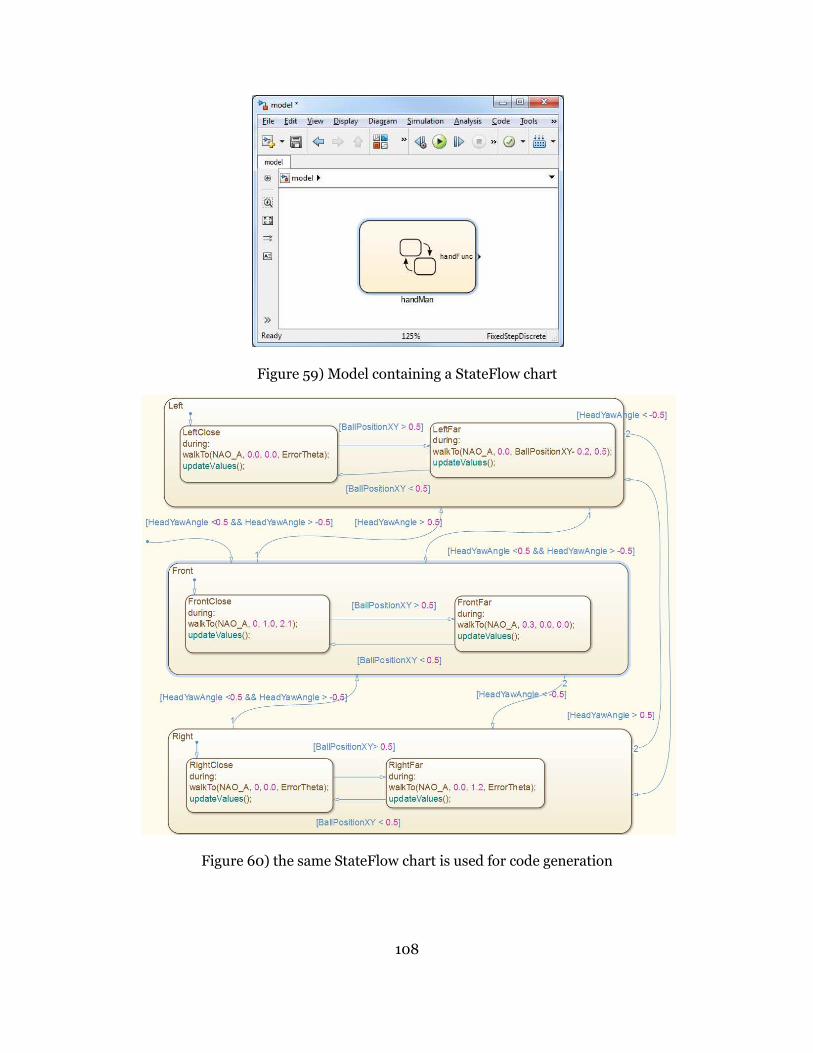
108
Figure 59) Model containing a StateFlow chart
Figure 60) the same StateFlow chart is used for code generation

109
Note) Since we are using QiBuild for compilation, we can modify the
configuration to be working with the naoqi-Atom-toolchain so we can cross compile and
run the code “on” the robot and not remotely from the host computer.
8.4.1 Procedure for generating code from a Simulink model for NAO
The following steps should be taken to properly generate code for the model and
integrate it into a qiBuild project.
1. First create a qiBuild project (qibuild workspace should be initiated already)
2. Configure and make the project
(>> qitoolchain info, >> qibuild config …, >> qibui ld make…)
3. go to CMAkeList.txt file and add the line
qi_use_lib(<ProjectName> ALCOMMON)
after
qi_create_bin(<ProjectName>"main.cpp")
4. Open the visual studio solution from the following folder inside your project
directory:
“build-<nameOfToolchain>”
5. There are 6 projects inside that solution one of which is the actual qiBuild project.
The rest are for testing and installation purposes. Click on the original project.
6. Create a directory (in windows explorer) inside that project named
“StateFlowModel”.
7. Open Matlab and then Simulink
8. Through Matlab interface navigate to your qiBuild project directory, then
“StateFlowModel” directory
9. Create a Simulink Model inside that directory
10. Before you continue, copy the “InterfaceAPI” folder to your project directory

110
11. Go to model explorer, in the model hierarchy pane, right click on the model and
select “Configuration …. >> import… and “import” the configuration file from
“InterfaceAPI” folder.
12. Go to the top level project directory (in Matlab) and add the whole directory and its
children files and folders to the Matlab path.
13. From StateFlow toolbox, insert a chart (C chart) and create your StateFlow
transition.
14. Make sure you are inside the project directory in Matlab workspace before starting
the simulation because when you start the simulation, Simulink creates the codes
and executable in your current active directory and if you are not in your project
folder it creates a mess.
15. After you simulate the model and make sure you have added the necessary local
variables and input outputs to the environment go for the code generation.
16. Before that right click on the state chart and in the properties, make the subsystem
as atomic and reusable function as shown in Figure 61.

111
Figure 61)Making the chart Atomic reusable function
17. Make sure before starting the code generation, tick the “Package code and artifacts”
and select a name for the Zip file so you have all the necessary files for compilation.
18. After unzipping the pack from Simulink (name it something like myModelPack),
now go to the Visual Studio project to start building the code.
19. click on your project and from the top menu go to project properties:
20. from the selected window, go to
Configuration Properties >> C/C++ >> General
and add the following include directories to the project:
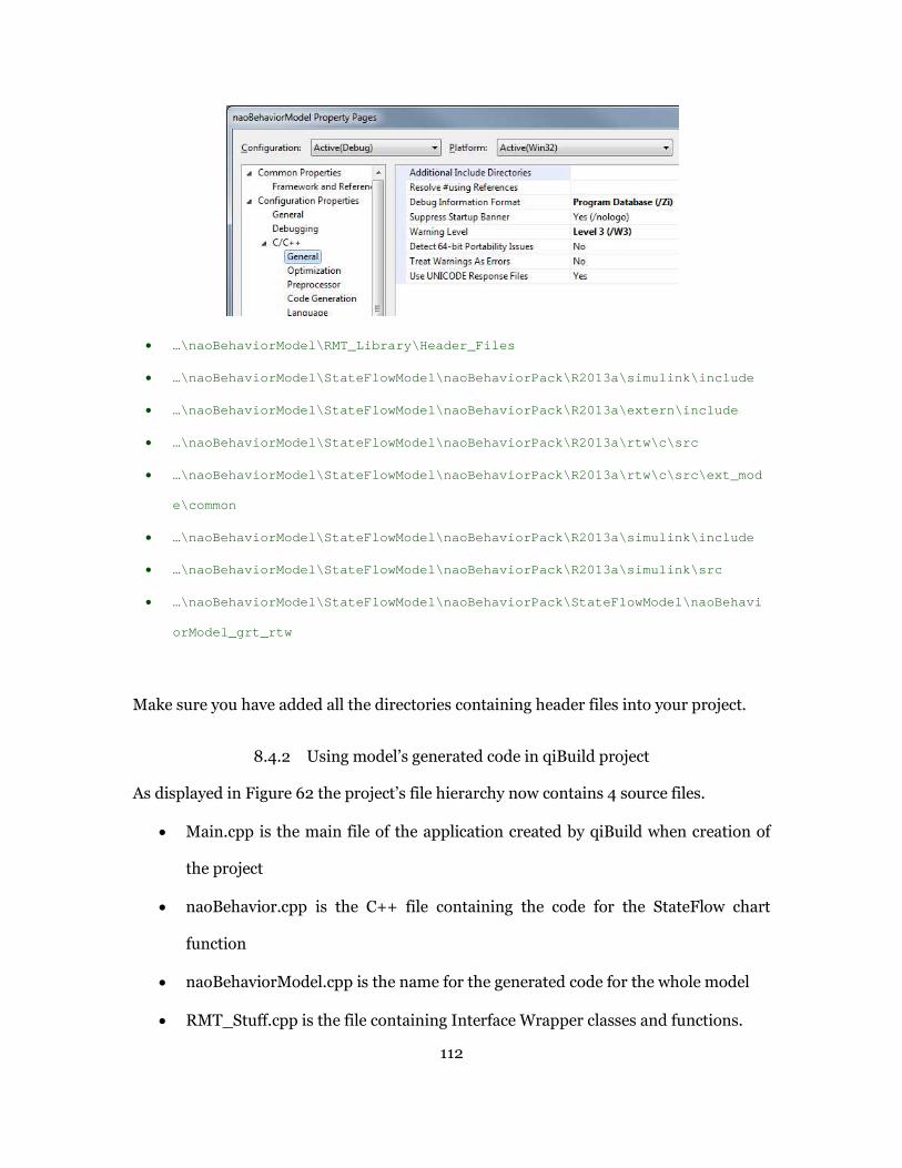
112
• …\naoBehaviorModel\RMT_Library\Header_Files
• …\naoBehaviorModel\StateFlowModel\naoBehaviorPack\R 2013a\simulink\include
• …\naoBehaviorModel\StateFlowModel\naoBehaviorPack\R 2013a\extern\include
• …\naoBehaviorModel\StateFlowModel\naoBehaviorPack\R 2013a\rtw\c\src
• …\naoBehaviorModel\StateFlowModel\naoBehaviorPack\R 2013a\rtw\c\src\ext_mod
e\common
• …\naoBehaviorModel\StateFlowModel\naoBehaviorPack\R 2013a\simulink\include
• …\naoBehaviorModel\StateFlowModel\naoBehaviorPack\R 2013a\simulink\src
• …\naoBehaviorModel\StateFlowModel\naoBehaviorPack\S tateFlowModel\naoBehavi
orModel_grt_rtw
Make sure you have added all the directories containing header files into your project.
8.4.2 Using model’s generated code in qiBuild project
As displayed in Figure 62 the project’s file hierarchy now contains 4 source files.
• Main.cpp is the main file of the application created by qiBuild when creation of
the project
• naoBehavior.cpp is the C++ file containing the code for the StateFlow chart
function
• naoBehaviorModel.cpp is the name for the generated code for the whole model
• RMT_Stuff.cpp is the file containing Interface Wrapper classes and functions.

113
Figure 62) qiBuild project file hierarchy
As mentioned earlier, the model’s generated code cannot be executed outside
Simulink since there is no Simulation Engine to take care of the process. Therefore we
need to call the model’s function manually from within the main function of the qiBuild
project as shown in Figure 63.
Figure 63) Imitating the behavior of simulation engine inside a qiBuild project
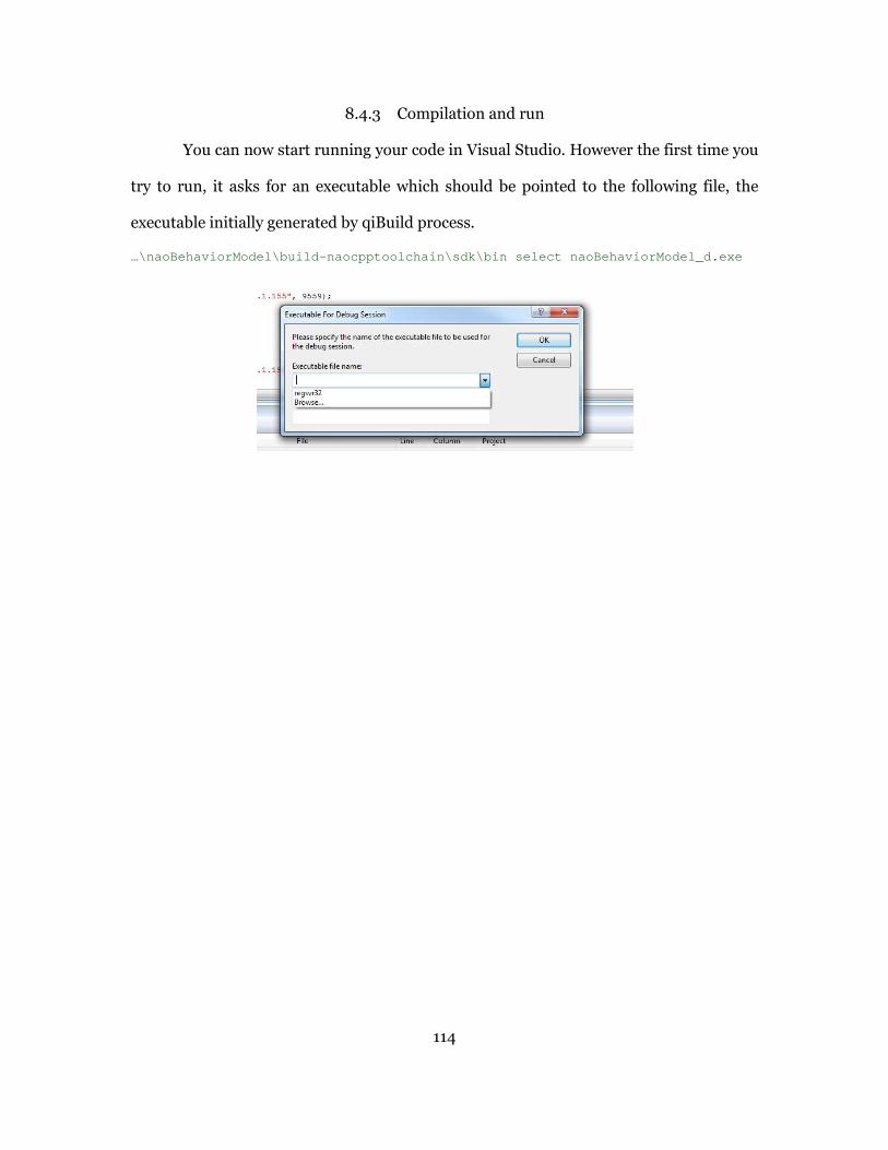
114
8.4.3 Compilation and run
You can now start running your code in Visual Studio. However the first time you
try to run, it asks for an executable which should be pointed to the following file, the
executable initially generated by qiBuild process.
…\naoBehaviorModel\build-naocpptoolchain\sdk\bin se lect naoBehaviorModel_d.exe

115
9 References
[1] E. A. Lee and S. A. Seshia, Introduction to Embedded Systems, 2011.
[2] Mathworks, "Simulink product page," Mathworks, 2013. [Online]. Available:
http://www.mathworks.com/products/simulink.
[3] Scilab, "Scicos: Block diagram modeler/simulator," 2013. [Online]. Available:
http://www.scicos.org/.
[4] Wolfram, "Wolfram SystemModeler," Wolfram, 2013. [Online]. Available:
http://www.wolfram.com/system-modeler/.
[5] Rethink Robotics, "Baxter, The Robot," [Online]. Available:
http://www.rethinkrobotics.com/products/baxter/.
[6] iRobot Corporation, "iRobot Roomba," [Online]. Available:
http://www.irobot.com/us/.
[7] Aldebaran Robotics, "NAO humanoid robots," [Online]. Available:
http://www.aldebaran-robotics.com/en/.
[8] University of Bremen, "Standard Platform League," 2013. [Online]. Available:
http://www.tzi.de/spl/bin/view/Website/WebHome.
[9] A. Ferrari, D. Grasso, G. Magnani, A. Fantechi and M. Tempestini, "The Metro Rio ATP
Case Study," Formal Methods for Industrial Critical Systems, Lecture Notes in
Computer Science, vol. 6371, pp. pp 1-16, 2010.
[10] "Webots simulator from Cyberbotics," Cyberbotics, [Online]. Available:
http://www.cyberbotics.com/overview.
[11] National Instruments, "NI LabVIEW for LEGO MINDSTORMS," 2013. [Online].
Available: http://www.ni.com/academic/mindstorms/.
[12] Wikipedia, "Cyber-physical system," [Online]. Available:
http://en.wikipedia.org/wiki/Cyber-physical_system.
[13] Mathworks, "Simulink Coder," Mathworks, [Online]. Available:
http://www.mathworks.com/products/simulink-coder/.

116
[14] MathWorks, "Model-Based Design video introduction," 2013. [Online]. Available:
http://www.mathworks.com/model-based-design/.
[15] N. Shankar and I. Saha, "ModelRob: A Simulink Library for Model-Based Development
of Robot Manipulators," in IEEE International Conference on Robotics and
Automation, 2012.
[16] F. Nagi, F. Hani Nprdin and E. S. Tan, "Mobile robot simulation and controller design
with Matlab/Simulink," in CARs&FOF, 2003.
[17] R. Gran, "What is simulation?," MathWorks, 2013. [Online]. Available:
http://www.mathworks.com/videos/what-is-simulation-73224.html.
[18] "Automatic Code Generation for embedded systems," 2013. [Online]. Available:
http://www.artist-
embedded.org/docs/Events/2007/China_School/Presentations/Caspi4_code_gen.pdf.
[19] P. Corke, "A robotics toolbox for MATLAB," in IEEE Robotics &Automation Magazine,
1996.
[20] J. Kim and I. Lee, "Modular code generation from hybrid automata based on data
dependency," in IEEE Real-time and embedded technology and application
symposium, 2003.
[21] S.-K. Su, "Model-Based Development of Multi-iRobot Simulation and Control, Masters
Thesis," Arizona State University, 2012.
[22] U.S. Naval Academy, "Matlab Toolbox for the iRobot Create (MTIC)," 2011. [Online].
Available: http://www.usna.edu/Users/weapsys/esposito/roomba.matlab/.
[23] MathWorks, "NAO Robot Ankle support from Simulink," 2013. [Online]. Available:
http://www.mathworks.com/hardware-support/nao-robot-simulink-ankle.html.
[24] F. D. Libera and H. Ishuguro, "ROSlink: Interfacing legacy systems with ROS".
[25] C. Crick, G. Jay, S. Osentosiki, B. Pitzer and O. C. Jenkins, in Proceedings of the 15th
International Symposium on Robotics Research, 2011.
[26] P. F. Smith, S. M. Prabhu and J. Friedman, "Best Practices for Establishing a Model-
Based Design Culture," SAE, 2007.
[27] C. Finucane, G. Jing and H. Kress-Gazit, "LTLMoP: Experimenting with Language,
Temporal Logic and robot control," in Intelligent Robots and Systems (IROS),
IEEE/RSJ International Conference on, 2010.

117
[28] L. A. Sucan, M. Moll and L. E. Kavraki, "The Open Motion Planning Library," IEEE
ROBOTICS & AUTOMATION MAGAZINE, pp. 72-82, December 2012.
[29] J. C. Jensen, "Elements of model-based design," University of California at Berkeley ,
2010.
[30] United States Naval Academy, "Matlab Toolbox for the iRobot Create (MTIC)," United
States Naval Academy, 2011. [Online]. Available:
http://www.usna.edu/Users/weapsys/esposito/roomba.matlab/.
[31] Cyber Physical Systems lab, "TALIRO Tols," 2013. [Online]. Available:
https://sites.google.com/a/asu.edu/s-taliro/home.
[32] G. Fainekos, S. Sankaranarayanan, K. Ueda and H. Yazarel, "Verification of automotive
control applications using S-TaLiRo," in American Control Conference, 2012.
[33] National Instruments, "LabVIEW System Design Software," 2013. [Online]. Available:
http://www.ni.com/labview/.
[34] Aldebaran Robotics, "NAO Robot H25 specification," Aldebaran Robotics, 2013.
[Online]. Available: https://community.aldebaran-robotics.com/nao/.
[35] Aldebaran Robotics, "NAoqi Software," 2013. [Online]. Available:
http://www.aldebaran-robotics.com/documentation/dev/naoqi/index.html.
[36] Aldebaran Robotics, "NAOqi Framework," 2013. [Online]. Available:
http://www.aldebaran-robotics.com/documentation/dev/naoqi/index.html.
[37] Aldebaran Robotics, "Choregraphe Software for NAO," Aldebaran Robotics, [Online].
Available: http://www.aldebaran-robotics.com/en/Discover-
NAO/Software/choregraphe.html.
[38] Aldebaran Robotics, "Monitor Software," 2013. [Online]. Available:
http://www.aldebaran-robotics.com/en/Discover-NAO/Software/monitor.html.
[39] Aldebaran Robotics, "qiBuild Programming guide," [Online]. Available:
http://www.aldebaran-robotics.com/documentation/qibuild/guide/index.html.
[40] Aldebaran Robotics, "NAO ALMotion API," [Online]. Available: http://www.aldebaran-
robotics.com/documentation/naoqi/motion/almotion-api.html.
[41] Aldebaran Robotics, "NAOqi modules API," [Online]. Available:
http://www.aldebaran-robotics.com/documentation/naoqi/index.html.
118
[42] Aldebaran Robotics, "NAO Joint Control API reference," [Online]. Available:
http://www.aldebaran-robotics.com/documentation/naoqi/motion/control-joint-
api.html.
[43] Aldebaran Robotics, "NAO Homepage," [Online]. Available: http://www.aldebaran-
robotics.com/documentation/index.html.
[44] P. Corke, "A robotics toolbox for MATLAB," in Robotics & Automation Magazine,
IEEE, 1996.
[45] Y. Annapureddy, C. Liu, G. Fainekos and S. Sankaranarayanan, "S-TaLiRo: A Tool for
Temporal Logic Falsification for Hybrid Systems," Tools and Algorithms for the
Construction and Analysis of Systems, Lecture Notes in Computer Science, vol. 6605,
pp. pp 254-257, 2011.
[46] A. Ulusoy, S. Smith, X. C. Ding and C. Belta, "Robust Multi-Robot Optimal Path
Planning with Temporal Logic Constraints," in IEEE International Conference on
Robotics and Automation, 2012.
[47] MathWorks, "Simulating Dynamic Systems," 2013. [Online]. Available:
http://www.mathworks.com/help/simulink/ug/simulating-dynamic-systems.html.
[48] MathWorks, "Modeling Dynamic Systems," 2013. [Online]. Available:
http://www.mathworks.com/help/simulink/ug/modeling-dynamic-systems.html.
[49] MathWorks, "Welcome to the Coders!," 2011. [Online]. Available:
http://blogs.mathworks.com/seth/2011/04/08/welcome-to-the-coders/.
[50] MathWorks, "Matlab Coder products," 2013. [Online]. Available:
http://www.mathworks.com/products/matlab-coder/description1.html.
[51] MathWorks, "Introduction to MEX-Files," 2013. [Online]. Available:
http://www.mathworks.com/help/matlab/matlab_external/introducing-mex-
files.html.
[52] dSpace GmbH, "TargetLink product page," 2013. [Online]. Available:
http://www.dspace.com/en/inc/home/products/sw/pcgs/targetli.cfm.
[53] dSpace, "TargetLink from dSpace," 2013. [Online]. Available:
http://en.wikipedia.org/wiki/TargetLink.
[54] MathWorks, "What is an S-Function?," 2013. [Online]. Available:
http://www.mathworks.com/help/simulink/sfg/what-is-an-s-function.html.
119
[55] MathWorks, "Available S-Function Implementations," 2013. [Online]. Available:
http://www.mathworks.com/help/simulink/sfg/available-s-function-
implementations.html.
[56] J. H. Saltzer and M. F. Kaashoek, Principles of Computer System Design: An
Introduction, Morgan Kaufmann, 2009.
[57] R. A. Brooks, "A Robust Layered Control System For A Mobile Robot," Massachusetts
Institute of Technology, 1985.
[58] R. A. Brooks, "A hardware retargetable distributed layered architecture for mobile
robot control," in IEEE International Conference on Robotics and Automation , 1987 .
[59] A. Karimoddini, G. Cai, B. M. Chen, H. Lin and T. H. Lee, "Hierarchical Control Design
of a UAV Helicopter," in Advances in Flight Control Systems, 2011.
[60] T. J. Koo, D. H. Shim, O. Shakernia, B. Sinopoli, F. Hoffmann and S. Sastry,
"Hierarchical Hybrid System Design on Berkeley UAV," in International Aerial
Robotics Competition, 1998.
[61] D. Shim, H. Kim and S. Sastry, "Hierarchical Flight Control System Synthesis for
Rotorcraft-based Unmanned Aerial Vehicles," in AIAA Guidance, Navigation, and
Control Conference and Exhibit, 2000.
[62] MathWorks, "C Charts in StateFlow," 2013. [Online]. Available:
http://www.mathworks.com/help/stateflow/ref/cchart.html.
[63] K. Manamcheri, S. Mitra, S. Bak and M. Caccamo, "A step towards verification and
synthesis from Simulink/Stateflow models," in Hybrid Systems: Computation and
Control (HSCC 2011), 2011.
[64] MathWorks, "Simulink Design Verifier," 2013. [Online]. Available:
http://www.mathworks.com/products/sldesignverifier/.
[65] MathWorks, "Static Analysis with Polyspace Products," 2013. [Online]. Available:
http://www.mathworks.com/products/polyspace/.
[66] Aldebaran Robotics, "Using qiBuild with Aldebaran packages," 2013. [Online].
Available: http://www.aldebaran-
robotics.com/documentation/dev/cpp/tutos/using_qibuild.html.
[67] R. Nikoukhah, "Scicos: Block diagram modeler/simulator," Metalau team, [Online].
Available: http://www.scicos.org/.
120
[68] N. Mavridis, W. Kazmi, P. Toulis and C. Ben-Abdelkader, "On The Synergies Between
Online Social Networking, Face Recognition And Interactive Robotics," in
International Conference on Computational Aspects of Social Networks, 2009.
[69] Lego, "Lego Mindstorms robotic platform," Lego , [Online]. Available:
http://mindstorms.lego.com/en-us/default.aspx.
[70] J. C. Jensen, "Elements of Model-Based Design," Electrical Engineering and Computer
Sciences, University of California at Berkeley, 2010.
[71] T. A. Henzinger, C. M. Kirsch, M. A. Sanvido and W. Pree, "From control models to
real-time code using Giotto," IEEE Control Systems Magazine, 2003.
[72] M. Frigerio, J. Buchli and D. Caldwell, "Model based code generation for kinematics
and dynamics computations in robot controllers," in 7th workshop on Software
Development and Integration in Robotics (ICRA SDIR VII), 2012.
[73] MathWorks, "S-Function Builder," 2013. [Online]. Available:
http://www.mathworks.com/help/simulink/slref/sfunctionbuilder.html.

121
10 APPENDIX A
THE C++ INTERFACE API DEFINTION

122
The C++ header file for C++ Manager class used in the C/C++ Interface API is
brought here. This is a builder class using which manager objects are created such as
NaoMotionManager and NaoRobotPostureManager.
#ifndef RMT_STUFF_H_ #define RMT_STUFF_H_ #include <iostream> #include <alproxies/almotionproxy.h> // RAMTIN ****** XXXXX #include <alproxies/alrobotpostureproxy.h> #include <alproxies/alredballtrackerproxy.h> #include <alproxies/alfacetrackerproxy.h> #include <windows.h> // RAMTIN ****** #include "rtwtypes.h" using namespace std; using namespace AL; struct NaoIpPort { string IP; int Port; }; // Function to parse the NaoAddress string variable into string variable "IP" and Integer variable "Port" NaoIpPort getNaoIpPort(string NaoAddress); // This struct can hold an object of type T such as ALMotionProxy or ALRobotPostureProxy objects as well as it's IP and Port template < class T> struct NaoObj { T ALObj; string IP; int port; }; template <class T> // An object containing a List of type T (ALmotionProxy, ALRobotPostureProxy etc.) class NaoObjectManager { private : std::vector<NaoObj<T>> NaoObjList; int objCount; // Number of objects already created and added to the list public : int isObjectCreated(string naoIP, int naoPort){ if (!NaoObjList.empty()){ for ( int i=0; i< objCount; i++)
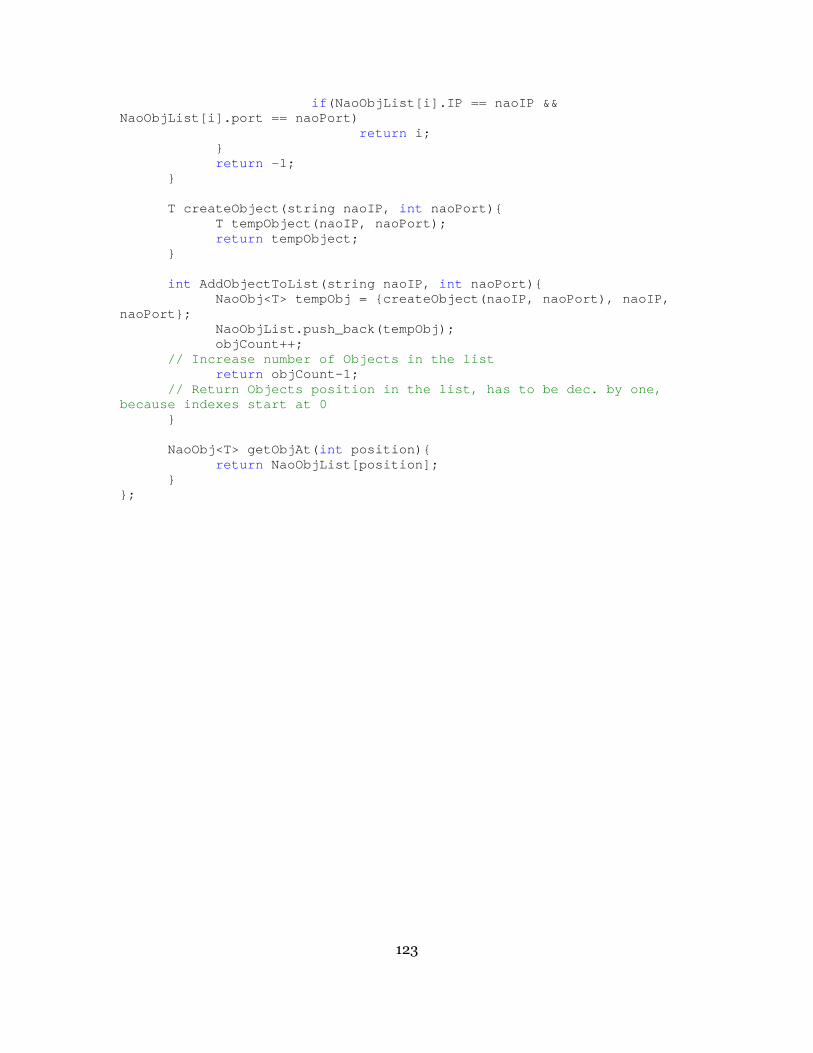
123
if (NaoObjList[i].IP == naoIP && NaoObjList[i].port == naoPort) return i; } return -1; } T createObject(string naoIP, int naoPort){ T tempObject(naoIP, naoPort); return tempObject; } int AddObjectToList(string naoIP, int naoPort){ NaoObj<T> tempObj = {createObject(naoIP, naoPort) , naoIP, naoPort}; NaoObjList.push_back(tempObj); objCount++; // Increase number of Objects in the list return objCount-1; // Return Objects position in the list, has to be d ec. by one, because indexes start at 0 } NaoObj<T> getObjAt( int position){ return NaoObjList[position]; } };

124
11 APPENDIX B
THE CPP FILE CONTAINING THE C INTERFACE
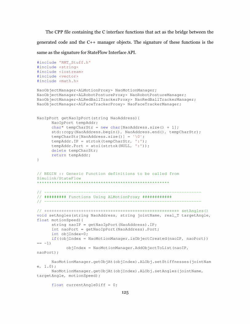
125
The CPP file containing the C interface functions that act as the bridge between the
generated code and the C++ manager objects. The signature of these functions is the
same as the signature for StateFlow Interface API.
#include "RMT_Stuff.h" #include <string> #include <iostream> #include <vector> #include <math.h> NaoObjectManager<ALMotionProxy> NaoMotionManager; NaoObjectManager<ALRobotPostureProxy> NaoRobotPostu reManager; NaoObjectManager<ALRedBallTrackerProxy> NaoRedBallT rackerManager; NaoObjectManager<ALFaceTrackerProxy> NaoFaceTracker Manager; NaoIpPort getNaoIpPort(string NaoAddress){ NaoIpPort tempAddr; char * tempCharStr = new char [NaoAddress.size() + 1]; std::copy(NaoAddress.begin(), NaoAddress.end(), te mpCharStr); tempCharStr[NaoAddress.size()] = '\0' ; tempAddr.IP = strtok(tempCharStr, ":" ); tempAddr.Port = atoi(strtok(NULL, ":" )); delete tempCharStr; return tempAddr; } // BEGIN :: Generic Function definitions to be call ed from Simulink/StateFlow *************************************************** *** // ------------------------------------------------ ---------------- // ######### Functions Using ALMotionProxy ######## #### // ------------------------------------------------ ---------------- // ++++++++++++++++++++++++++++++++++++++++++++++++ +++++++ setAngles() void setAngles(string NaoAddress, string jointName, rea l_T targetAngle, float motionSpeed){ string naoIP = getNaoIpPort(NaoAddress).IP; int naoPort = getNaoIpPort(NaoAddress).Port; int objIndex=0; if ((objIndex = NaoMotionManager.isObjectCreated(naoIP , naoPort)) == -1) objIndex = NaoMotionManager.AddObjectToList(naoIP , naoPort); NaoMotionManager.getObjAt(objIndex).ALObj.setStiff nesses(jointName, 1.0); NaoMotionManager.getObjAt(objIndex).ALObj.setAngle s(jointName, targetAngle, motionSpeed); float currentAngleDiff = 0;
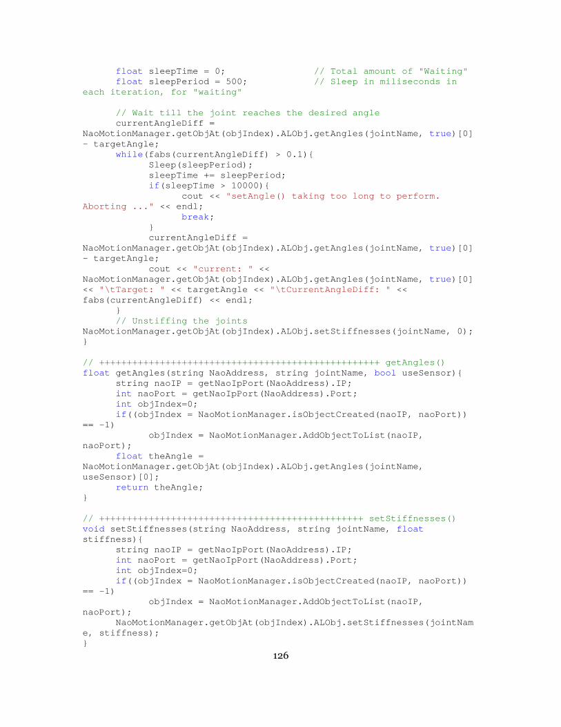
126
float sleepTime = 0; // Total amount of "Waiting" float sleepPeriod = 500; // Sleep in miliseconds in each iteration, for "waiting" // Wait till the joint reaches the desired angle currentAngleDiff = NaoMotionManager.getObjAt(objIndex).ALObj.getAngles (jointName, true )[0] - targetAngle; while (fabs(currentAngleDiff) > 0.1){ Sleep(sleepPeriod); sleepTime += sleepPeriod; if (sleepTime > 10000){ cout << "setAngle() taking too long to perform. Aborting ..." << endl; break ; } currentAngleDiff = NaoMotionManager.getObjAt(objIndex).ALObj.getAngles (jointName, true )[0] - targetAngle; cout << "current: " << NaoMotionManager.getObjAt(objIndex).ALObj.getAngles (jointName, true )[0] << "\tTarget: " << targetAngle << "\tCurrentAngleDiff: " << fabs(currentAngleDiff) << endl; } // Unstiffing the joints NaoMotionManager.getObjAt(objIndex).ALObj.setStiffn esses(jointName, 0); } // ++++++++++++++++++++++++++++++++++++++++++++++++ +++ getAngles() float getAngles(string NaoAddress, string jointName, bool useSensor){ string naoIP = getNaoIpPort(NaoAddress).IP; int naoPort = getNaoIpPort(NaoAddress).Port; int objIndex=0; if ((objIndex = NaoMotionManager.isObjectCreated(naoIP , naoPort)) == -1) objIndex = NaoMotionManager.AddObjectToList(naoIP , naoPort); float theAngle = NaoMotionManager.getObjAt(objIndex).ALObj.getAngles (jointName, useSensor)[0]; return theAngle; } // ++++++++++++++++++++++++++++++++++++++++++++++++ setStiffnesses() void setStiffnesses(string NaoAddress, string jointName , float stiffness){ string naoIP = getNaoIpPort(NaoAddress).IP; int naoPort = getNaoIpPort(NaoAddress).Port; int objIndex=0; if ((objIndex = NaoMotionManager.isObjectCreated(naoIP , naoPort)) == -1) objIndex = NaoMotionManager.AddObjectToList(naoIP , naoPort); NaoMotionManager.getObjAt(objIndex).ALObj.setStiff nesses(jointName, stiffness); }
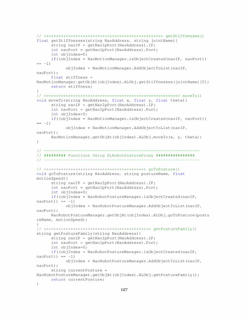
127
// ++++++++++++++++++++++++++++++++++++++++++++++++ + getStiffnesses() float getStiffnesses(string NaoAddress, string jointName ){ string naoIP = getNaoIpPort(NaoAddress).IP; int naoPort = getNaoIpPort(NaoAddress).Port; int objIndex=0; if ((objIndex = NaoMotionManager.isObjectCreated(naoIP , naoPort)) == -1) objIndex = NaoMotionManager.AddObjectToList(naoIP , naoPort); float stiffness = NaoMotionManager.getObjAt(objIndex).ALObj.getStiffn esses(jointName)[0]; return stiffness; } // ++++++++++++++++++++++++++++++++++++++++++++++++ ++++++++ moveTo() void moveTo(string NaoAddress, float x, float y, float theta){ string naoIP = getNaoIpPort(NaoAddress).IP; int naoPort = getNaoIpPort(NaoAddress).Port; int objIndex=0; if ((objIndex = NaoMotionManager.isObjectCreated(naoIP , naoPort)) == -1) objIndex = NaoMotionManager.AddObjectToList(naoIP , naoPort); NaoMotionManager.getObjAt(objIndex).ALObj.moveTo(x , y, theta); } // ------------------------------------------------ ---------------- // ######### Functions Using ALRobotPostureProxy ## ############## // ------------------------------------------------ ---------------- // ++++++++++++++++++++++++++++++++++++++++++ goToP osture() void goToPosture(string NaoAddress, string postureName, float motionSpeed){ string naoIP = getNaoIpPort(NaoAddress).IP; int naoPort = getNaoIpPort(NaoAddress).Port; int objIndex=0; if ((objIndex = NaoRobotPostureManager.isObjectCreated (naoIP, naoPort)) == -1) objIndex = NaoRobotPostureManager.AddObjectToList (naoIP, naoPort); NaoRobotPostureManager.getObjAt(objIndex).ALObj.go ToPosture(postureName, motionSpeed); } // ++++++++++++++++++++++++++++++++++++++++++++ get PostureFamily() string getPostureFamily(string NaoAddress){ string naoIP = getNaoIpPort(NaoAddress).IP; int naoPort = getNaoIpPort(NaoAddress).Port; int objIndex=0; if ((objIndex = NaoRobotPostureManager.isObjectCreated (naoIP, naoPort)) == -1) objIndex = NaoRobotPostureManager.AddObjectToList (naoIP, naoPort); string currentPosture = NaoRobotPostureManager.getObjAt(objIndex).ALObj.get PostureFamily(); return currentPosture; }

128
// ------------------------------------------------ --------------- // ########### Functions Using ALRedBallTrackerProx y ############## // ------------------------------------------------ ---------------- // ++++++++++++++++++++++++++++++++++++++++++++++++ +++ RBgetPosition() vector< float > RBgetPosition(string NaoAddress){ string naoIP = getNaoIpPort(NaoAddress).IP; int naoPort = getNaoIpPort(NaoAddress).Port; int objIndex=0; if ((objIndex = NaoRedBallTrackerManager.isObjectCreat ed(naoIP, naoPort)) == -1) objIndex = NaoRedBallTrackerManager.AddObjectToLi st(naoIP, naoPort); vector< float > redBallPosition = NaoRedBallTrackerManager.getObjAt(objIndex).ALObj.g etPosition(); return redBallPosition; } // ++++++++++++++++++++++++++++++++++++++++++++++++ ++ RBstartTracker() void RBstartTracker(string NaoAddress){ string naoIP = getNaoIpPort(NaoAddress).IP; int naoPort = getNaoIpPort(NaoAddress).Port; int objIndex=0; if ((objIndex = NaoRedBallTrackerManager.isObjectCreat ed(naoIP, naoPort)) == -1) objIndex = NaoRedBallTrackerManager.AddObjectToLi st(naoIP, naoPort); NaoRedBallTrackerManager.getObjAt(objIndex).ALObj. startTracker(); } // ++++++++++++++++++++++++++++++++++++++++++++++++ +++ RBstopTracker() void RBstopTracker(string NaoAddress){ string naoIP = getNaoIpPort(NaoAddress).IP; int naoPort = getNaoIpPort(NaoAddress).Port; int objIndex=0; if ((objIndex = NaoRedBallTrackerManager.isObjectCreat ed(naoIP, naoPort)) == -1) objIndex = NaoRedBallTrackerManager.AddObjectToLi st(naoIP, naoPort); NaoRedBallTrackerManager.getObjAt(objIndex).ALObj. stopTracker(); } // ++++++++++++++++++++++++++++++++++++++++++++++++ RBsetWholeBodyOn() void RBsetWholeBodyOn(string NaoAddress, bool wholeBodyOn){ string naoIP = getNaoIpPort(NaoAddress).IP; int naoPort = getNaoIpPort(NaoAddress).Port; int objIndex=0; if ((objIndex = NaoRedBallTrackerManager.isObjectCreat ed(naoIP, naoPort)) == -1) objIndex = NaoRedBallTrackerManager.AddObjectToLi st(naoIP, naoPort); NaoRedBallTrackerManager.getObjAt(objIndex).ALObj. setWholeBodyOn(wholeBodyOn); }

129
12 APPENDIX C
STATEFLOW® INTERFACE API
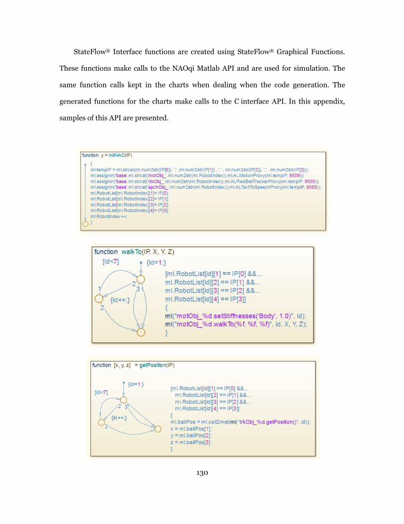
130
StateFlow® Interface functions are created using StateFlow® Graphical Functions.
These functions make calls to the NAOqi Matlab API and are used for simulation. The
same function calls kept in the charts when dealing when the code generation. The
generated functions for the charts make calls to the C interface API. In this appendix,
samples of this API are presented.

131
13 APPENDIX D
MATLAB CODE FOR RMT_NAOSETANGLE SIMULINK M-S-FUNCTION BLOCK.
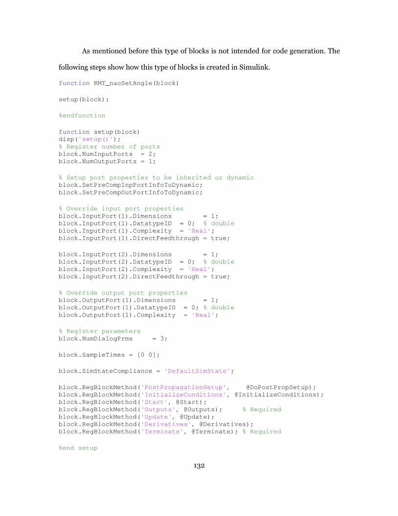
132
As mentioned before this type of blocks is not intended for code generation. The
following steps show how this type of blocks is created in Simulink.
function RMT_naoSetAngle(block) setup(block); %endfunction function setup(block) disp( 'setup()' ); % Register number of ports block.NumInputPorts = 2; block.NumOutputPorts = 1; % Setup port properties to be inherited or dynamic block.SetPreCompInpPortInfoToDynamic; block.SetPreCompOutPortInfoToDynamic; % Override input port properties block.InputPort(1).Dimensions = 1; block.InputPort(1).DatatypeID = 0; % double block.InputPort(1).Complexity = 'Real' ; block.InputPort(1).DirectFeedthrough = true; block.InputPort(2).Dimensions = 1; block.InputPort(2).DatatypeID = 0; % double block.InputPort(2).Complexity = 'Real' ; block.InputPort(2).DirectFeedthrough = true; % Override output port properties block.OutputPort(1).Dimensions = 1; block.OutputPort(1).DatatypeID = 0; % double block.OutputPort(1).Complexity = 'Real' ; % Register parameters block.NumDialogPrms = 3; block.SampleTimes = [0 0]; block.SimStateCompliance = 'DefaultSimState' ; block.RegBlockMethod( 'PostPropagationSetup' , @DoPostPropSetup); block.RegBlockMethod( 'InitializeConditions' , @InitializeConditions); block.RegBlockMethod( 'Start' , @Start); block.RegBlockMethod( 'Outputs' , @Outputs); % Required block.RegBlockMethod( 'Update' , @Update); block.RegBlockMethod( 'Derivatives' , @Derivatives); block.RegBlockMethod( 'Terminate' , @Terminate); % Required %end setup
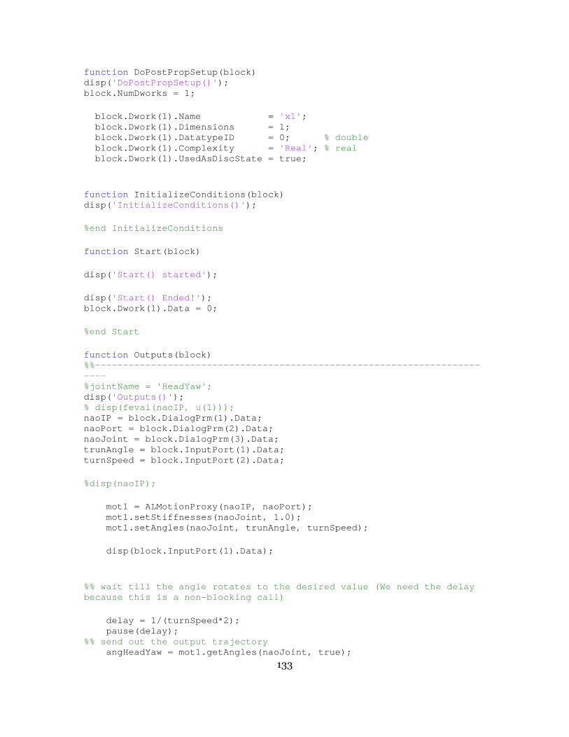
133
function DoPostPropSetup(block) disp( 'DoPostPropSetup()' ); block.NumDworks = 1; block.Dwork(1).Name = 'x1' ; block.Dwork(1).Dimensions = 1; block.Dwork(1).DatatypeID = 0; % double block.Dwork(1).Complexity = 'Real' ; % real block.Dwork(1).UsedAsDiscState = true; function InitializeConditions(block) disp( 'InitializeConditions()' ); %end InitializeConditions function Start(block) disp( 'Start() started' ); disp( 'Start() Ended!' ); block.Dwork(1).Data = 0; %end Start function Outputs(block) %%------------------------------------------------- ------------------------ %jointName = 'HeadYaw'; disp( 'Outputs()' ); % disp(feval(naoIP, u(1))); naoIP = block.DialogPrm(1).Data; naoPort = block.DialogPrm(2).Data; naoJoint = block.DialogPrm(3).Data; trunAngle = block.InputPort(1).Data; turnSpeed = block.InputPort(2).Data; %disp(naoIP); mot1 = ALMotionProxy(naoIP, naoPort); mot1.setStiffnesses(naoJoint, 1.0); mot1.setAngles(naoJoint, trunAngle, turnSpeed); disp(block.InputPort(1).Data); %% wait till the angle rotates to the desired value (We need the delay because this is a non-blocking call) delay = 1/(turnSpeed*2); pause(delay); %% send out the output trajectory angHeadYaw = mot1.getAngles(naoJoint, true);

134
%disp(angHeadYaw); block.OutputPort(1).Data = cell2mat(angHeadYaw) ; %block.OutputPort(1).Data = block.Dwork(1).Data + block.InputPort(1).Data; %% unStiff the joint %block.OutputPort(1).Data = 3*block.InputPort(1).Da ta; mot1.setStiffnesses(naoJoint, 0.0); disp( 'Outputs()ENDED!' ); %end Outputs %%------------------------------------------------- ------------------ function Update(block) disp( 'Update()' ); block.Dwork(1).Data = block.InputPort(1).Data; %end Update function Derivatives(block) disp( 'Derivatives()' ); %end Derivatives function Terminate(block) disp( 'Terminate()' ); %end Terminate

135
14 APPENDIX E
MATLABPROXY.CPP: THE CODE FOR MEX FUNCTION MATLABPROXY()

136
* Copyright Aldebaran Robotics #include "matlabproxy.h" #include "matlabconvert.h" #include <alcore/alptr.h> #include <alvalue/alvalue.h> #include <alremotecall/alremoteproxy.h> #include "mex.h" #include "matrix.h" #include <iostream> #include <vector> #include <string> using namespace AL; void mexFunction( int nlhs, mxArray *plhs[], int nrhs, const mxArray *prhs[]) { if (nrhs < 3){ mexErrMsgTxt( "Usage: proxy = ALProxy('moduleName','ip',port)" ); return ; } // get module name std::string moduleName, ip; int port; char buff[40]; mxGetString(prhs[0],buff,39); moduleName = buff; // get ip mxGetString(prhs[1],buff,39); ip = buff; // get port port = ( int ) mxGetScalar(prhs[2]); // create a proxy with NaoQi API ALProxyRemote *proxy = new ALProxyRemote(moduleName, ip, port); // store pointer in Matlab plhs[0] = getPtr2MxArray(proxy); } // constructor matlabproxy::matlabproxy( ) {} // destructor matlabproxy::~matlabproxy() {}

137
15 APPENDIX F
MATLABCALL.CPP: THE CODE FOR MEX FUNCTION MATLABCALL()
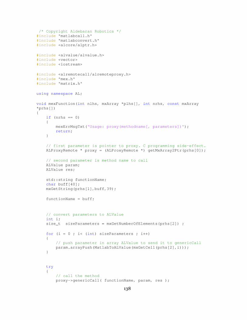
138
/* Copyright Aldebaran Robotics */ #include "matlabcall.h" #include "matlabconvert.h" #include <alcore/alptr.h>
#include <alvalue/alvalue.h> #include <vector> #include <iostream> #include <alremotecall/alremoteproxy.h> #include "mex.h" #include "matrix.h"
using namespace AL; void mexFunction( int nlhs, mxArray *plhs[], int nrhs, const mxArray *prhs[]) { if (nrhs == 0) { mexErrMsgTxt( "Usage: proxy(methodname[, parameters])" ); return ; } // first parameter is pointer to proxy. C programmi ng side-effect. ALProxyRemote * proxy = (ALProxyRemote *) getMx Array2Ptr(prhs[0]); // second parameter is method name to call ALValue param; ALValue res; std::string functionName; char buff[40]; mxGetString(prhs[1],buff,39); functionName = buff; // convert parameters to ALValue int i; size_t sizeParameters = mxGetNumberOfElements( prhs[2]) ; for (i = 0 ; i< ( int ) sizeParameters ; i++) { // push parameter in array ALValue to send it to ge nericCall param.arrayPush(MatlabToALValue(mxGetCell(p rhs[2],i))); } try { // call the method proxy->genericCall( functionName, param, re s );
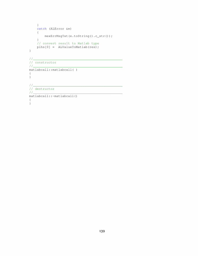
139
} catch (ALError &e) { mexErrMsgTxt(e.toString().c_str()); } // convert result to Matlab type plhs[0] = ALValueToMatlab(res); } //______________________________________________ // constructor //______________________________________________ matlabcall::matlabcall( ) { } //______________________________________________ // destructor //______________________________________________ matlabcall::~matlabcall() { }
Top Related