


Languages
Pages
Legal

MODBUS Tables Supplement COI/FET2XX/MOD/TBL–EN
AquaMaster 3Electromagnetic flowmeter
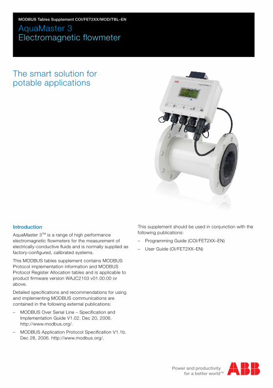
The smart solution for potable applications
Introduction
AquaMaster 3TM is a range of high performance electromagnetic flowmeters for the measurement of electrically-conductive fluids and is normally supplied as factory-configured, calibrated systems.
This MODBUS tables supplement contains MODBUS Protocol implementation information and MODBUS Protocol Register Allocation tables and is applicable to product firmware version WAJC2103 v01.00.00 or above.
Detailed specifications and recommendations for using and implementing MODBUS communications are contained in the following external publications:
– MODBUS Over Serial Line – Specification and Implementation Guide V1.02. Dec 20, 2006.http://www.modbus.org/.
– MODBUS Application Protocol Specification V1.1b. Dec 28, 2006. http://www.modbus.org/.
This supplement should be used in conjunction with the following publications:
– Programming Guide (COI/FET2XX–EN)
– User Guide (OI/FET2XX–EN)

The CompanyWe are an established world force in the design and manufacture of instrumentation for industrial process control, flow measurement, gas and liquid analysis and environmental applications.
As a part of ABB, a world leader in process automation technology, we offer customers application expertise, service and support worldwide.
We are committed to teamwork, high quality manufacturing, advanced technology and unrivalled service and support.
The quality, accuracy and performance of the Company’s products result from over 100 years experience, combined with a continuous program of innovative design and development to incorporate the latest technology.
Quality Control
The UKAS Calibration Laboratory No. 0255 is just one of the ten flow calibration plants operated by the Company and is indicative of our dedication to quality and accuracy.
����
UKAS Calibration Laboratory No. 0255

AquaMaster 3 Electromagnetic flowmeter
MODBUS Tables Supplement COI/FET2XX/MOD/TBL-EN 1
MODBUS Protocol
1 MODBUS Protocol ............................................................................................ 2 1.1 Implementation Information.......................................................................... 2 1.2 AquaMaster 3 MODBUS Register Mapping.................................................. 3 1.3 Register Usage ............................................................................................ 4
1.3.1 RW 1-Bit............................................................................................... 4 1.3.2 RO 1-Bit ............................................................................................... 5 1.3.3 RO 8/16-Bit .......................................................................................... 5 1.3.4 RO String.............................................................................................. 6 1.3.5 RO 32-Bit ............................................................................................. 7 1.3.6 RO Float ............................................................................................... 8 1.3.7 RW 8/16-Bit ......................................................................................... 8 1.3.8 RW String ........................................................................................... 10 1.3.9 RW 32-Bit........................................................................................... 12 1.3.10 RW Float .......................................................................................... 13
Appendix A – MODBUS Register Allocation Tables......................................... 14 RW 1-Bit .......................................................................................................... 14 RO 1-Bit .......................................................................................................... 14 RO 8/16-Bit ..................................................................................................... 15 RO String......................................................................................................... 16 RO 32-Bit ........................................................................................................ 17 RO Float .......................................................................................................... 18 RW 8/16-Bit..................................................................................................... 19 RW String ........................................................................................................ 21 RW 32-Bit ........................................................................................................ 22 RW Float.......................................................................................................... 23 Tables of Settings ............................................................................................ 24
Notes .................................................................................................................. 26

AquaMaster 3 Electromagnetic flowmeter
MODBUS Tables Supplement COI/FET2XX/MOD/TBL-EN 2
MODBUS Protocol
1 MODBUS Protocol AquaMaster 3 RS485 MODBUS option implements the MODBUS over Serial Line protocol described in the following MODBUS publications:
MODBUS Over Serial Line – Specification and Implementation Guide V1.02. Dec 20, 2006.
MODBUS Application Protocol Specification V1.1b. Dec 28, 2006.
Section 1.1 provides specific AquaMaster 3 MODBUS implementation details and section 1.2 provides an overview of the AquaMaster 3 MODBUS Register mapping.
1.1 Implementation Information The following information should be considered when implementing a MODBUS master to communicate with AquaMaster 3:
Transmission mode: Remote Terminal Unit (RTU) slave.
Response time-out: 1s
Turnaround delay: 800ms
Interface power-up considerations. The AquaMaster 3 MODBUS interface has been designed for low power consumption so that it can be used with battery or renewable energy supplies (as well as with mains power). When the AquaMaster 3 MODBUS interface is inactive (no characters received for 10s) it is switched into a low power state. In this low power state it is not possible for AquaMaster 3 to receive the first characters sent to it although the interface will be 'woken up' within 1s by communications activity. Therefore, after any period of inactivity longer than 10s it is necessary for a MODBUS master to perform 1 retry to communicate with AquaMaster 3s.
AquaMaster 3 Electromagnetic flowmeter
MODBUS Tables Supplement COI/FET2XX/MOD/TBL-EN 3
MODBUS Protocol
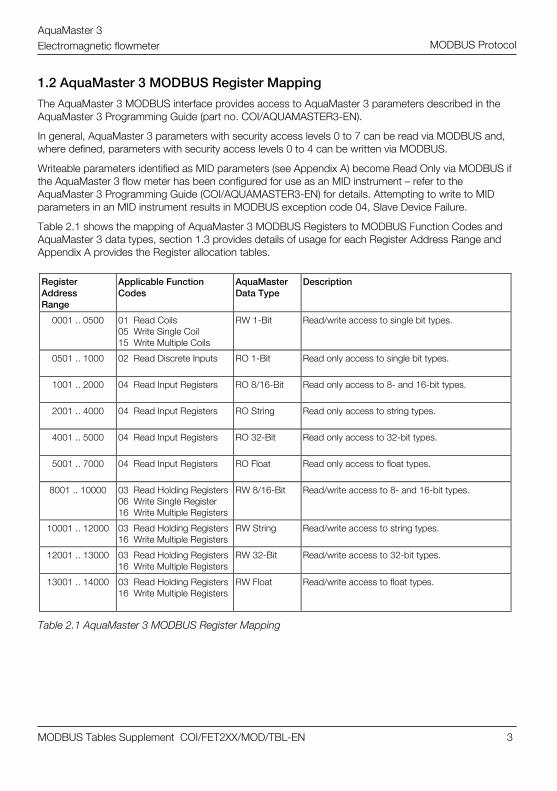
1.2 AquaMaster 3 MODBUS Register Mapping The AquaMaster 3 MODBUS interface provides access to AquaMaster 3 parameters described in the AquaMaster 3 Programming Guide (part no. COI/AQUAMASTER3-EN).
In general, AquaMaster 3 parameters with security access levels 0 to 7 can be read via MODBUS and, where defined, parameters with security access levels 0 to 4 can be written via MODBUS.
Writeable parameters identified as MID parameters (see Appendix A) become Read Only via MODBUS if the AquaMaster 3 flow meter has been configured for use as an MID instrument – refer to the AquaMaster 3 Programming Guide (COI/AQUAMASTER3-EN) for details. Attempting to write to MID parameters in an MID instrument results in MODBUS exception code 04, Slave Device Failure.
Table 2.1 shows the mapping of AquaMaster 3 MODBUS Registers to MODBUS Function Codes and AquaMaster 3 data types, section 1.3 provides details of usage for each Register Address Range and Appendix A provides the Register allocation tables. Register Address Range
Applicable Function Codes
AquaMaster Data Type
Description
0001 .. 0500 01 Read Coils 05 Write Single Coil 15 Write Multiple Coils
RW 1-Bit Read/write access to single bit types.
0501 .. 1000 02 Read Discrete Inputs RO 1-Bit Read only access to single bit types.
1001 .. 2000 04 Read Input Registers RO 8/16-Bit Read only access to 8- and 16-bit types.
2001 .. 4000 04 Read Input Registers RO String Read only access to string types.
4001 .. 5000 04 Read Input Registers RO 32-Bit Read only access to 32-bit types.
5001 .. 7000 04 Read Input Registers RO Float Read only access to float types.
8001 .. 10000 03 Read Holding Registers 06 Write Single Register 16 Write Multiple Registers
RW 8/16-Bit Read/write access to 8- and 16-bit types.
10001 .. 12000 03 Read Holding Registers 16 Write Multiple Registers
RW String Read/write access to string types.
12001 .. 13000 03 Read Holding Registers 16 Write Multiple Registers
RW 32-Bit Read/write access to 32-bit types.
13001 .. 14000 03 Read Holding Registers 16 Write Multiple Registers
RW Float Read/write access to float types.
Table 2.1 AquaMaster 3 MODBUS Register Mapping

AquaMaster 3 Electromagnetic flowmeter
MODBUS Tables Supplement COI/FET2XX/MOD/TBL-EN 4
MODBUS Protocol
1.3 Register Usage
This section provides further information and worked examples of MODBUS protocol messages, application data units (ADUs) and their responses for each of the Register ranges corresponding to AquaMaster 3 data types.
Note: MODBUS data model register addressing starts from XXXX1 but within the MODBUS protocol data unit (PDU) addressing starts from XXXX0.
Register addresses shown in the Register allocation tables (Appendix A) are MODBUS data model register addresses.
1.3.1 RW 1-Bit
Read/Write access to single bit types.
Read Coils 1 to 14
Read all RW 1-Bit items
Request Message (Hex) Response Message (Hex) Error Message (Hex)
Address 01 Address 01 Function 81
Function 01 Function 01 Exception Code Exception Code
Starting Address Hi 00 Byte count 02
Starting Address Lo 00 Outputs status 00008-00001* 61
Quantity of Inputs Hi 00 Outputs status 00014-00009* 05
Quantity of Inputs Lo 0E CRC 50
CRC BD CRC 6F
CRC CE
*Coils 1,6,7,9,11 = 1
*Coils 2,3,4,5,8,10,12,13,14 = 0
Write Single Coil 3
var54: Display Net Total = ON
Request Message (Hex) Response Message (Hex) Error Message (Hex)
Address 01 Address 01 Function 85
Function 05 Function 05 Exception Code Exception Code
Output address Hi 00 Output Address Hi 00
Output Address Lo 02 Output Address Lo 02
Output Value FF Output Value FF
Output Value 00 Output Value 00
CRC 2D CRC 2D
CRC FA CRC FA

AquaMaster 3 Electromagnetic flowmeter
MODBUS Tables Supplement COI/FET2XX/MOD/TBL-EN 5
MODBUS Protocol
1.3.2 RO 1-Bit
Read-only access to single bit types.
Read Discrete Inputs 501 to 503
Read all RO 1-bits
Request Message (Hex) Response Message (Hex) Error Message (Hex)
Address 01 Address 01 Function 82
Function 02 Function 02 Exception Code Exception Code
Starting Address Hi 01 Byte Count 01
Starting Address Lo f4 Outputs Status* 06
Quantity of Inputs Hi 00 CRC 21
Quantity of Inputs Lo 03 CRC 8a
CRC 78
CRC 05
*Outputs status = 06
Output status
Bit Register Value Variable Meaning
0 501 0 007 Flow sensor is not reverse wired
1 502 1 008 Flow sensor is a Probe
2 503 1 416 MID (read only switch) is Active
3 to 7 — — — Not Used
1.3.3 RO 8/16-Bit
Read-only access to 8- and 16-bit types.
8-Bit quantities use the Lo byte of Register Value. The Hi byte is 'don't care' and shows value 0 in Response Messages.
Read Input Register 1002
var12 – Flow sensor settling time (battery power) (16-bit)
Request Message (Hex) Response Message (Hex) Error Message (Hex)
Address 01 Address 01 Function 84
Function 04 Function 04 Exception Code Exception Code
Starting Address Hi 03 Byte Count 02
Starting Address Lo e9 Register Value Hi* 01
Quantity of Inputs Hi 00 Register Value Lo* d1
Quantity of Inputs Lo 01 CRC 78
CRC e0 CRC fc
CRC 7a
*Register Value = 01d1h = 465
AquaMaster 3 Electromagnetic flowmeter
MODBUS Tables Supplement COI/FET2XX/MOD/TBL-EN 6
MODBUS Protocol
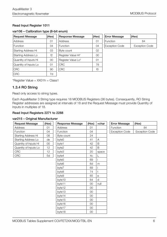
Read Input Register 1011
var106 – Calibration type (8-bit enum)
Request Message (Hex) Response Message (Hex) Error Message (Hex)
Address 01 Address 01 Function 84
Function 04 Function 04 Exception Code Exception Code
Starting Address Hi 03 Byte count 02
Starting Address Lo f2 Register Value Hi* 00
Quantity of Inputs Hi 00 Register Value Lo* 01
Quantity of Inputs Lo 01 CRC 78
CRC 90 CRC f0
CRC 7d
*Register Value = XX01h = Class1
1.3.4 RO String
Read only access to string types.
Each AquaMaster 3 String type requires 18 MODBUS Registers (36 bytes). Consequently, RO String Register addresses are assigned at intervals of 18 and the Request Message must provide Quantity of Inputs in multiples of 18.
Read Input Registers 2271 to 2288
var215 – Original Manufacturer
Request Message (Hex) Response Message (Hex) =char Error Message (Hex) Address 01 Address 01 Function 84 Function 04 Function 04 Exception Code Exception Code Starting Address Hi 08 Byte count 24 Starting Address Lo de byte0 41 A Quantity of Inputs Hi 00 byte1 42 B Quantity of Inputs Lo 12 byte2 42 B CRC 12 byte3 20 space CRC 5d byte4 4c L byte5 69 i byte6 6d m byte7 69 i byte8 74 t byte9 65 e byte10 64 d byte11 00 null byte12 00 byte13 00 byte14 00 byte15 00 byte16 00 byte17 00 byte18 00

AquaMaster 3 Electromagnetic flowmeter
MODBUS Tables Supplement COI/FET2XX/MOD/TBL-EN 7
MODBUS Protocol
Request Message (Hex) Response Message (Hex) =char Error Message (Hex) byte19 00 byte20 00 byte21 00 byte22 00 byte23 00 byte24 00 byte25 00 byte26 00 byte27 00 byte28 00 byte29 00 byte30 00 byte31 00 byte32 00 byte33 00 byte34 00 byte35 00 CRC 2c CRC ce
1.3.5 RO 32-Bit
Read-only access to 32-bit types.
Each AquaMaster 3 32-Bit type requires 2 MODBUS Registers (4 bytes). Consequently, RO 32-Bit Register addresses are assigned at intervals of 2 and the Request Message must provide Quantity of Inputs in multiples of 2.
32-Bit quantities are arranged in big-endian order.
Read Input Registers 4013 to 4014
var207 – Transmitter Unique ID
Request Message (Hex) Response Message (Hex) Error Message (Hex)
Address 01 Address 01 Function 84
Function 04 Function 04 Exception Code Exception Code
Starting Address Hi 0f Byte Count 04
Starting Address Lo ac H Register Value Hi 00
Quantity of Inputs Hi 00 H Register Value Lo 00
Quantity of Inputs Lo 02 L Register Value Hi 00
CRC b2 L Register Value Lo 1b
=27
CRC fe CRC bb
CRC 8f

AquaMaster 3 Electromagnetic flowmeter
MODBUS Tables Supplement COI/FET2XX/MOD/TBL-EN 8
MODBUS Protocol
1.3.6 RO Float
Read-only access to float types.
Each AquaMaster 3 float type requires 2 MODBUS Registers (4 bytes). Consequently, RO float Register addresses are assigned at intervals of 2 and the Request Message must provide Quantity of Inputs in multiples of 2.
Float values use IEEE-754 format arranged in big-endian order.
Read Input Registers 5033 to 5034
var237 – Calibrated bore Request Message (Hex) Response Message (Hex) Error Message (Hex) Address 01 Address 01 Function 84 Function 04 Function 04 Exception Code Exception Code Starting Address Hi 13 Byte count 04 Starting Address Lo a8 H Register Value Hi 41 Quantity of Inputs Hi 00 H Register Value Lo 20 Quantity of Inputs Lo 02 L Register Value Hi 00 CRC f4 L Register Value Lo 00
=10.0
CRC af CRC ee CRC 72
1.3.7 RW 8/16-Bit
Read/write access to 8- and 16-bit types.
8-Bit quantities use the Lo byte of Register Value. The Hi byte is 'don't care' and can be set to value 0 in Request Messages and shows value 0 in Response Messages.
Read Holding Register 8009
var69 – Pulse maximum frequency
Request Message (Hex) Response Message (Hex) Error Message (Hex)
Address 01 Address 01 Function 83
Function 03 Function 03 Exception Code Exception Code
Starting Address Hi 1f Byte count 02
Starting Address Lo 48 Register Value Hi 00
Quantity of Inputs Hi 00 Register Value Lo 32 =50
Quantity of Inputs Lo 01 CRC 39
CRC 03 CRC 91
CRC c8

AquaMaster 3 Electromagnetic flowmeter
MODBUS Tables Supplement COI/FET2XX/MOD/TBL-EN 9
MODBUS Protocol
Write Single Register 8019
var125 – Trip point for high flow = 14
Request Message (Hex) Response Message (Hex) Error Message (Hex)
Address 01 Address 01 Function 86
Function 06 Function 06 Exception Code Exception Code
Starting Address Hi 1f Starting Address Hi 1f
Starting Address Lo 52 Starting Address Lo 52
Register Value Hi 00 Register Value Hi 00
Register Value Lo 0e =14
Register Value Lo 0e =14
CRC ae CRC ae
CRC 0b CRC 0b
Write Multiple Registers 8019
var125 – Trip point for high flow = 15
Request Message (Hex) Response Message (Hex) Error Message (Hex)
Address 01 Address 01 Function 90
Function 10 Function 10 Exception Code Exception Code
Starting Address Hi 1f Starting Address Hi 1f
Starting Address Lo 52 Starting Address Lo 52
Quantity of Registers Hi 00 Quantity of Registers Hi 00
Quantity of Registers Lo 01 Quantity of Registers Lo 01
Byte Count 02 CRC a7
Register Value Hi 00 CRC cc
Register Value Lo 0f =15
CRC 05
CRC 27
AquaMaster 3 Electromagnetic flowmeter
MODBUS Tables Supplement COI/FET2XX/MOD/TBL-EN 10
MODBUS Protocol
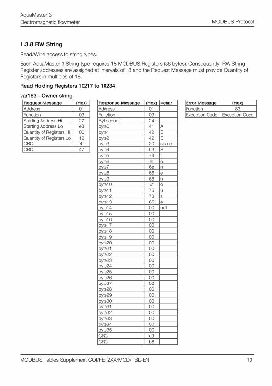
1.3.8 RW String
Read/Write access to string types.
Each AquaMaster 3 String type requires 18 MODBUS Registers (36 bytes). Consequently, RW String Register addresses are assigned at intervals of 18 and the Request Message must provide Quantity of Registers in multiples of 18.
Read Holding Registers 10217 to 10234
var163 – Owner string Request Message (Hex) Response Message (Hex) =char Error Message (Hex) Address 01 Address 01 Function 83 Function 03 Function 03 Exception Code Exception Code Starting Address Hi 27 Byte count 24 Starting Address Lo e8 byte0 41 A Quantity of Registers Hi 00 byte1 42 B Quantity of Registers Lo 12 byte2 42 B CRC 4f byte3 20 space CRC 47 byte4 53 S byte5 74 t byte6 6f o byte7 6e n byte8 65 e byte9 68 h byte10 6f o byte11 75 u byte12 73 s byte13 65 e byte14 00 null byte15 00 byte16 00 byte17 00 byte18 00 byte19 00 byte20 00 byte21 00 byte22 00 byte23 00 byte24 00 byte25 00 byte26 00 byte27 00 byte28 00 byte29 00 byte30 00 byte31 00 byte32 00 byte33 00 byte34 00 byte35 00 CRC a9 CRC b8

AquaMaster 3 Electromagnetic flowmeter
MODBUS Tables Supplement COI/FET2XX/MOD/TBL-EN 11
MODBUS Protocol
Write Multiple Registers 10199 to 10216
var162 – Location string = "Flow D&D Office UK" Request Message (Hex) =char Response Message (Hex) Error Message (Hex) Address 01 Address 01 Function 90 Function 10 Function 10 Exception Code Exception Code Starting Address Hi 27 Starting Address Hi 27 Starting Address Lo d6 Starting Address Lo d6 Quantity of Registers Hi 00 Quantity of Registers Hi 00 Quantity of Registers Lo 12 Quantity of Registers Lo 12 Byte count 24 CRC ab byte0 46 F CRC 48 byte1 6c l byte2 6f o byte3 77 w byte4 20 space byte5 44 D byte6 26 & byte7 44 D byte8 20 space byte9 4f O byte10 66 f byte11 66 f byte12 69 i byte13 63 c byte14 65 e byte15 20 space byte16 55 U byte17 4b K byte18 00 null byte19 00 byte20 00 byte21 00 byte22 00 byte23 00 byte24 00 byte25 00 byte26 00 byte27 00 byte28 00 byte29 00 byte30 00 byte31 00 byte32 00 byte33 00 byte34 00 byte35 00 CRC 9a CRC e9

AquaMaster 3 Electromagnetic flowmeter
MODBUS Tables Supplement COI/FET2XX/MOD/TBL-EN 12
MODBUS Protocol
1.3.9 RW 32-Bit
Read/Write access to 32-bit types.
Each AquaMaster 3 RW 32-Bit type requires 2 MODBUS Registers (4 bytes). Consequently, RW 32-Bit Register addresses are assigned at intervals of 2 and the Request Message must provide Quantity of Registers in multiples of 2.
32-Bit quantities are arranged in big-endian order.
Read Holding Registers 12003 to 12004
var224 – Totaliser Forward
Request Message (Hex) Response Message (Hex) Error Message (Hex)
Address 01 Address 01 Function 83
Function 03 Function 03 Exception Code Exception Code
Starting Address Hi 2e Byte count 04
Starting Address Lo e2 Register Value H Hi 00
Quantity of Inputs Hi 00 Register Value H Lo 3d
Quantity of Inputs Lo 02 Register Value L Hi ac
CRC 6d Register Value L Lo f0
=4041968
CRC 15 CRC 39
CRC 91

AquaMaster 3 Electromagnetic flowmeter
MODBUS Tables Supplement COI/FET2XX/MOD/TBL-EN 13
MODBUS Protocol
1.3.10 RW Float
Read/Write access to float types.
Float values use IEEE-754 format arranged in big-endian order.
Each AquaMaster 3 RW Float type requires 2 MODBUS Registers (4 bytes). Consequently, RW Float Register addresses are assigned at intervals of 2 and Fn03 (Read Holding Register) Request Messages must provide Quantity of Registers in multiples of 2.
Read Holding Registers 13005 to 13006
var30 – Insertion probe – profile factor
Request Message (Hex) Response Message (Hex) Error Message (Hex)
Address 01 Address 01 Function 83
Function 03 Function 03 Exception Code Exception Code
Starting Address Hi 32 Byte count 04
Starting Address Lo cc Register Value H Hi 3f
Quantity of Inputs Hi 00 Register Value H Lo 66
Quantity of Inputs Lo 02 Register Value L Hi 66
CRC 0a Register Value L Lo 67
=0.9000000
CRC 8c CRC 7c
CRC 72
Each AquaMaster 3 RW Float type requires 2 MODBUS Registers (4 bytes). Consequently, RW Float Register addresses are assigned at intervals of 2 and Fn16 (Write Multiple Register) Request Messages must provide Quantity of Registers in multiples of 2 and Byte Count in multiples of 4.
Write Multiple Registers 13009 to 13010
var32 – Probe pipe bore = 10.0000
Request Message (Hex) Response Message (Hex) Error Message (Hex)
Address 01 Address 01 Function 90
Function 10 Function 10 Exception Code Exception Code
Starting Address Hi 32 Starting Address Hi 32
Starting Address Lo d0 Starting Address Lo d0
Quantity of Registers Hi 00 Quantity of Registers Hi 00
Quantity of Registers Lo 02 Quantity of Registers Lo 02
Byte count 04 CRC 4e
Register Value H Hi 41 CRC 89
Register Value H Lo 20
Register Value L Hi 00
Register Value L Lo 00
10.0000
CRC a6
CRC 64

AquaMaster 3 Electromagnetic flowmeter
MODBUS Tables Supplement COI/FET2XX/MOD/TBL-EN 14
MODBUS Protocol
Appendix A – MODBUS Register Allocation Tables Note: MODBUS data model register addressing starts from XXXX1 but within the MODBUS protocol data unit (PDU) addressing starts from XXXX0.
Register addresses shown in these Register allocation tables are MODBUS data model register addresses.
RW 1-Bit Coil
Address AquaMaster 3
Parameter Name Range Note
1 052 DisplayForwardTotal 0=Off, 1=On Show Forward Total on AquaMaster 3 LCD display
2 053 DisplayReverseTotal 0=Off, 1=On —
3 054 DisplayNetTotal 0=Off, 1=On —
4 055 DisplayTariffA 0=Off, 1=On —
5 056 DisplayTariffB 0=Off, 1=On —
6 059 DisplayFlowRate 0=Off, 1=On —
7 060 DisplayFlowVelocity 0=Off, 1=On —
8 061 DisplayPressure 0=Off, 1=On —
9 062 DisplayDateAndTime 0=Off, 1=On Show Date & Time on AquaMaster 3 LCD display
10 066 PressureDisplayType 0=Absolute, 1=Gauge
—
11 321 DisableDiagnostics 0=No, 1=Yes —
12 343 ABB Reserved — —
13 356 ABB Reserved — —
14 375 ABB Reserved — —
RO 1—Bit
Address AquaMaster 3 Parameter
Name Range Note
501 007 FlowSensorReverseWired 0=No, 1=Yes —
502 008 FlowSensorIsAProbe 0=Full Bore,1=Probe Flow sensor type
503 416 ReadOnlySwitchState 0=Off, 1=On MID switch

AquaMaster 3 Electromagnetic flowmeter
MODBUS Tables Supplement COI/FET2XX/MOD/TBL-EN 15
MODBUS Protocol
RO 8/16—Bit Address AquaMaster 3
Parameter Name Size
(bytes) Range/Units Note
1001 011 FlowSensorZero 2 x0.01 mms—1 Sensor zero correction (mains power)
1002 012 FlowSensorSettlingTimeConstant 2 x0.1 ms Sensor settling time (battery power)
1003 021 FlowSensorLining 1 0 to 23 See Table A.1 Materials
1004 022 FlowSensorElectrodes 1 0 to 23 See Table A.1 Materials
1005 023 FlowSensorFlanges 1 0 to 23 See Table A.1 Materials
1006 024 FlowSensorBody 1 0 to 23 See Table A.1 Materials
1007 029 FlowSensorSettlingTimeHigh 2 x0.1 ms Sensor settling time (mains power)
1008 034 ABB Reserved 2 — —
1009 035 ABB Reserved 2 — —
1010 036 ABB Reserved 1 — —
1011 106 CalibrationType 1 0 to 4 See Table A.2 Calibration Types
1012 148 ABB Reserved 1 — —
1013 151 SupplierCode 2 — Logger supplier
1014 155 ABB Reserved 1 — —
1015 156 ABB Reserved 1 — —
1016 195 FlowSensorZeroLowCurrent 2 x 0.01 mms—1 Sensor zero correction (battery power)
1017 208 ABB Reserved 2 — —
1018 291 ABB Reserved 1 — —
1019 319 TxrPowerType 1 0 to 2 0 = Battery, 1 = Mains, 2 = Renewable
1020 324 ABB Reserved 1 — —
1021 340 ExtPowerStatus 1 0 to 7 See Table A.3 External Power Status
1022 348 ABB Reserved 2 — —
1023 349 IntPowerStatus 1 0 to 2 0 = OK, 1 = Low, 2 = Fail
1024 368 ABB Reserved 1 — —
1025 371 ABB Reserved 1 — —
1026 384 ABB Reserved 1 — —
1027 387 ABB Reserved 1 — —
1028 393 ABB Reserved 1 — —
1029 396 ABB Reserved 1 — —
1030 414 LoggerEnabled 1 0 = No, 1 = Yes
—
AquaMaster 3 Electromagnetic flowmeter
MODBUS Tables Supplement COI/FET2XX/MOD/TBL-EN 16
MODBUS Protocol
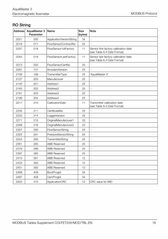
RO String Address AquaMaster 3
Parameter Name Size
(bytes) Note
2001 000 ApplicationVersionString 34 —
2019 017 FlowSensorContractNo 25 —
2037 018 FlowSensor1stFactory 11 Sensor first factory calibration date (see Table A.4 Date Format)
2055 019 FlowSensorLastFactory 11 Sensor last factory calibration date (see Table A.4 Date Format)
2073 020 FlowSensorCertNo 25 —
2091 101 AmodemVersion 25 —
2109 199 TransmitterType 25 'AquaMaster 3'
2127 200 Manufacturer 25 —
2145 201 Address1 25 —
2163 202 Address2 25 —
2181 203 Address3 25 —
2199 204 Address4 25 —
2217 210 CalibrationDate 11 Transmitter calibration date (see Table A.4 Date Format)
2235 211 CertificateNo 25 —
2253 214 LoggerVersion 25 —
2271 215 OriginalManufacturer1 33 —
2289 216 OriginalManufacturer2 33 —
2307 280 FlowSensorString 25 —
2325 281 PressureSensorString 25 —
2343 282 TransmitterString 25 —
2361 285 ABB Reserved 25 —
2379 286 ABB Reserved 25 —
2397 365 ABB Reserved 25 —
2415 381 ABB Reserved 12 —
2433 383 ABB Reserved 12 —
2451 392 ABB Reserved 12 —
2469 408 BootProgId 34 —
2487 409 UamProgId 34 —
2505 415 ApplicationCRC 12 CRC value for MID
AquaMaster 3 Electromagnetic flowmeter
MODBUS Tables Supplement COI/FET2XX/MOD/TBL-EN 17
MODBUS Protocol
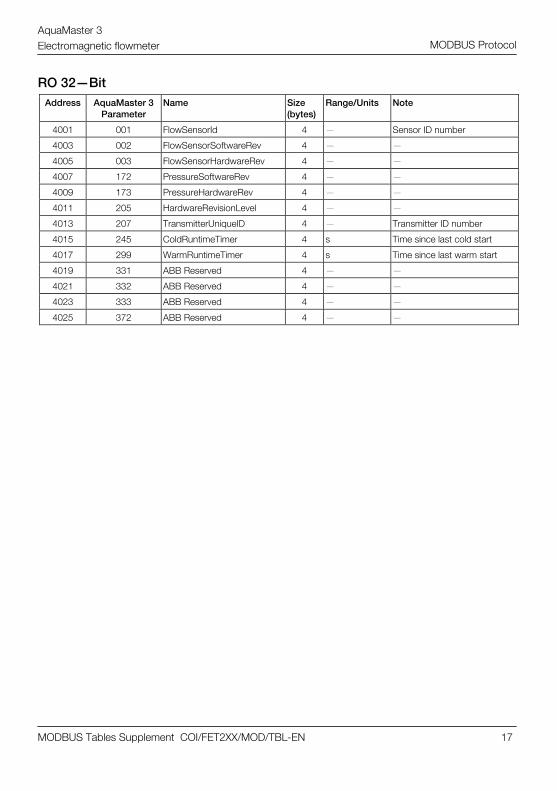
RO 32—Bit Address AquaMaster 3
Parameter Name Size
(bytes) Range/Units Note
4001 001 FlowSensorId 4 — Sensor ID number
4003 002 FlowSensorSoftwareRev 4 — —
4005 003 FlowSensorHardwareRev 4 — —
4007 172 PressureSoftwareRev 4 — —
4009 173 PressureHardwareRev 4 — —
4011 205 HardwareRevisionLevel 4 — —
4013 207 TransmitterUniqueID 4 — Transmitter ID number
4015 245 ColdRuntimeTimer 4 s Time since last cold start
4017 299 WarmRuntimeTimer 4 s Time since last warm start
4019 331 ABB Reserved 4 — —
4021 332 ABB Reserved 4 — —
4023 333 ABB Reserved 4 — —
4025 372 ABB Reserved 4 — —

AquaMaster 3 Electromagnetic flowmeter
MODBUS Tables Supplement COI/FET2XX/MOD/TBL-EN 18
MODBUS Protocol
RO Float Address AquaMaster 3
Parameter Name Size
(bytes) Range/Units Note
5001 004 ABB Reserved 4 — — 5003 006 ABB Reserved 4 — — 5005 009 ABB Reserved 4 — — 5007 010 FlowSensorCalFactor 4 — Factory sensor span factor 5009 013 HeadSpanLow 4 — Factory span adjustment 5011 016 EmptyPipeZero 4 — Factory empty pipe zero correction 5013 146 ABB Reserved 4 — — 5015 147 ABB Reserved 4 — — 5017 217 FlowRate 4 User flow units — 5019 218 FlowPercent 4 % — 5021 219 ABB Reserved 4 — — 5023 220 ABB Reserved 4 — — 5025 222 Pressure 4 User units — 5027 223 PressurePercent 4 % — 5029 234 LeftElectrode 4 kOhm — 5031 235 RightElectrode 4 kOhm — 5033 237 CalibratedBore 4 mm — 5035 238 ISpan 4 — Factory coil current span factor 5037 239 IZero 4 — Factory coil current zero correction 5039 243 CoilCurrent 4 A 5041 258 PulseOutput 4 Hz 5043 294 SignalCalHighCurrent 4 — Factory transmitter span (mains) 5045 295 ZeroOffsetHighCurrent 4 — Factory transmitter zero (mains) 5047 296 SignalCalLowCurrent 4 — Factory transmitter span (battery) 5049 297 ZeroOffsetLowCurrent 4 — Factory transmitter zero (battery) 5051 298 CalibratedVelocity 4 ms—1 — 5053 310 ABB Reserved 4 — — 5055 311 ABB Reserved 4 — — 5057 312 VoltageReference 4 V — 5059 313 PressureGain 4 — Factory transmitter pressure span 5061 314 PressureOffset 4 — Factory transmitter pressure zero 5063 328 SigAVolts 4 V Electrode A voltage 5065 329 SigBVolts 4 V Electrode B voltage 5067 341 ABB Reserved 4 — — 5069 376 PowerVExt 4 V External power supply voltage 5071 377 PowerV3V8 4 V Internal 3V8 voltage 5073 378 PowerV3V2 4 V Internal 3V2 voltage
AquaMaster 3 Electromagnetic flowmeter
MODBUS Tables Supplement COI/FET2XX/MOD/TBL-EN 19
MODBUS Protocol
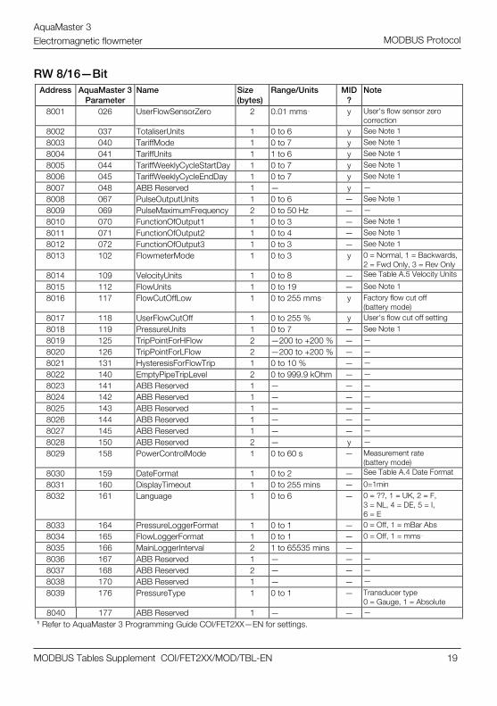
RW 8/16—Bit Address AquaMaster 3
Parameter Name Size
(bytes) Range/Units MID
? Note
8001 026 UserFlowSensorZero 2 0.01 mms—1 y User's flow sensor zero correction
8002 037 TotaliserUnits 1 0 to 6 y See Note 1 8003 040 TariffMode 1 0 to 7 y See Note 1 8004 041 TariffUnits 1 1 to 6 y See Note 1 8005 044 TariffWeeklyCycleStartDay 1 0 to 7 y See Note 1 8006 045 TariffWeeklyCycleEndDay 1 0 to 7 y See Note 1 8007 048 ABB Reserved 1 — y — 8008 067 PulseOutputUnits 1 0 to 6 — See Note 1 8009 069 PulseMaximumFrequency 2 0 to 50 Hz — — 8010 070 FunctionOfOutput1 1 0 to 3 — See Note 1 8011 071 FunctionOfOutput2 1 0 to 4 — See Note 1 8012 072 FunctionOfOutput3 1 0 to 3 — See Note 1 8013 102 FlowmeterMode 1 0 to 3 y 0 = Normal, 1 = Backwards,
2 = Fwd Only, 3 = Rev Only 8014 109 VelocityUnits 1 0 to 8 — See Table A.5 Velocity Units
8015 112 FlowUnits 1 0 to 19 — See Note 1 8016 117 FlowCutOffLow 1 0 to 255 mms—1 y Factory flow cut off
(battery mode) 8017 118 UserFlowCutOff 1 0 to 255 % y User's flow cut off setting 8018 119 PressureUnits 1 0 to 7 — See Note 1 8019 125 TripPointForHFlow 2 —200 to +200 % — — 8020 126 TripPointForLFlow 2 —200 to +200 % — — 8021 131 HysteresisForFlowTrip 1 0 to 10 % — — 8022 140 EmptyPipeTripLevel 2 0 to 999.9 kOhm — — 8023 141 ABB Reserved 1 — — — 8024 142 ABB Reserved 1 — — — 8025 143 ABB Reserved 1 — — — 8026 144 ABB Reserved 1 — — — 8027 145 ABB Reserved 1 — — — 8028 150 ABB Reserved 2 — y — 8029 158 PowerControlMode 1 0 to 60 s — Measurement rate
(battery mode) 8030 159 DateFormat 1 0 to 2 — See Table A.4 Date Format
8031 160 DisplayTimeout 1 0 to 255 mins — 0=1min 8032 161 Language 1 0 to 6 — 0 = ??, 1 = UK, 2 = F,
3 = NL, 4 = DE, 5 = I, 6 = E
8033 164 PressureLoggerFormat 1 0 to 1 — 0 = Off, 1 = mBar Abs 8034 165 FlowLoggerFormat 1 0 to 1 — 0 = Off, 1 = mms—1 8035 166 MainLoggerInterval 2 1 to 65535 mins — 8036 167 ABB Reserved 1 — — — 8037 168 ABB Reserved 2 — — — 8038 170 ABB Reserved 1 — — — 8039 176 PressureType 1 0 to 1 — Transducer type
0 = Gauge, 1 = Absolute 8040 177 ABB Reserved 1 — — —
1 Refer to AquaMaster 3 Programming Guide COI/FET2XX—EN for settings.
AquaMaster 3 Electromagnetic flowmeter
MODBUS Tables Supplement COI/FET2XX/MOD/TBL-EN 20
MODBUS Protocol
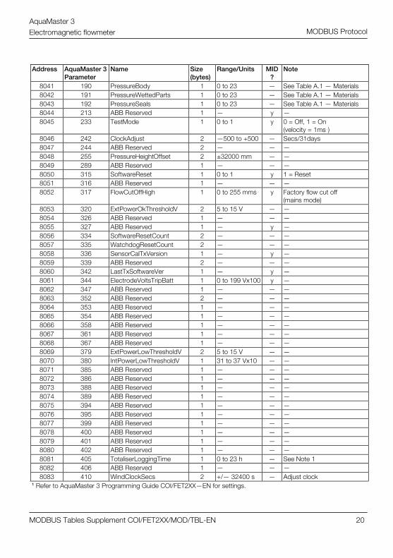
Address AquaMaster 3
Parameter Name Size
(bytes) Range/Units MID
? Note
8041 190 PressureBody 1 0 to 23 — See Table A.1 — Materials 8042 191 PressureWettedParts 1 0 to 23 — See Table A.1 — Materials 8043 192 PressureSeals 1 0 to 23 — See Table A.1 — Materials 8044 213 ABB Reserved 1 — y — 8045 233 TestMode 1 0 to 1 y 0 = Off, 1 = On
(velocity = 1ms—1) 8046 242 ClockAdjust 2 —500 to +500 — Secs/31days 8047 244 ABB Reserved 2 — — — 8048 255 PressureHeightOffset 2 ±32000 mm — — 8049 289 ABB Reserved 1 — — — 8050 315 SoftwareReset 1 0 to 1 y 1 = Reset 8051 316 ABB Reserved 1 — — — 8052 317 FlowCutOffHigh 1 0 to 255 mms—1 y Factory flow cut off
(mains mode) 8053 320 ExtPowerOkThresholdV 2 5 to 15 V — — 8054 326 ABB Reserved 1 — — — 8055 327 ABB Reserved 1 — y — 8056 334 SoftwareResetCount 2 — — — 8057 335 WatchdogResetCount 2 — — — 8058 336 SensorCalTxVersion 1 — y — 8059 339 ABB Reserved 2 — — — 8060 342 LastTxSoftwareVer 1 — y — 8061 344 ElectrodeVoltsTripBatt 1 0 to 199 Vx100 y — 8062 347 ABB Reserved 1 — — — 8063 352 ABB Reserved 2 — — — 8064 353 ABB Reserved 1 — — — 8065 354 ABB Reserved 1 — — — 8066 358 ABB Reserved 1 — — — 8067 361 ABB Reserved 1 — — — 8068 367 ABB Reserved 1 — — — 8069 379 ExtPowerLowThresholdV 2 5 to 15 V — — 8070 380 IntPowerLowThresholdV 1 31 to 37 Vx10 — — 8071 385 ABB Reserved 1 — — — 8072 386 ABB Reserved 1 — — — 8073 388 ABB Reserved 1 — — — 8074 389 ABB Reserved 1 — — — 8075 394 ABB Reserved 1 — — — 8076 395 ABB Reserved 1 — — — 8077 399 ABB Reserved 1 — — — 8078 400 ABB Reserved 1 — — — 8079 401 ABB Reserved 1 — — — 8080 402 ABB Reserved 1 — — — 8081 405 TotaliserLoggingTime 1 0 to 23 h — See Note 1 8082 406 ABB Reserved 1 — — — 8083 410 WindClockSecs 2 +/— 32400 s — Adjust clock
1 Refer to AquaMaster 3 Programming Guide COI/FET2XX—EN for settings.
AquaMaster 3 Electromagnetic flowmeter
MODBUS Tables Supplement COI/FET2XX/MOD/TBL-EN 21
MODBUS Protocol
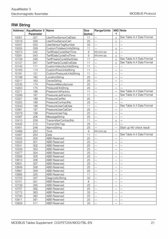
RW String Address AquaMaster 3
Parameter Name Size
(bytes) Range/Units MID
? Note
10001 027 UserFlowSensorCalDate 11 — y See Table A.4 Date Format 10019 028 UserFlowSensorCert 25 — y — 10037 033 UserSensorTagNumber 33 — — — 10055 039 CustomTotaliserUnitsString 11 — y — 10073 042 TariffDailyCycleStartTime 9 hh:mm:ss y — 10091 043 TariffDailyCycleEndTime 9 hh:mm:ss y — 10109 046 TariffYearlyCycleStartDate 11 — y See Table A.4 Date Format 10127 047 TariffYearlyCycleEndDate 11 — y See Table A.4 Date Format 10145 111 CustomVelocityUnitsString 11 — — — 10163 114 CustomFlowUnitsString 11 — — — 10181 121 CustomPressureUnitsString 11 — — — 10199 162 LocationString 25 — — — 10217 163 OwnerString 25 — — — 10235 174 PressureManufacturer 25 — — — 10253 175 PressureInfoString 25 — — — 10271 186 Pressure1stFactory 11 — — See Table A.4 Date Format 10289 187 PressureLastFactory 11 — — See Table A.4 Date Format 10307 188 PressureCertNo 25 — — 10325 189 PressureContractNo 25 — — — 10343 196 PressureUserCalDate 11 — — See Table A.4 Date Format 10361 197 PressureUserCalCert 25 — — — 10379 198 PressureUserTag 25 — — — 10397 206 MessageString 25 — — — 10415 209 TransmitterContractNo 11 — y — 10433 212 TransmitterTag 25 — — — 10451 246 AlarmsString 25 — — Start up NV check result 10469 253 Time 9 hh:mm:ss — 10487 254 Date 11 — — See Table A.4 Date Format 10505 300 ABB Reserved 25 — — — 10523 301 ABB Reserved 25 — — — 10541 302 ABB Reserved 25 — — — 10559 303 ABB Reserved 25 — — — 10577 304 ABB Reserved 25 — — — 10595 305 ABB Reserved 25 — — — 10613 306 ABB Reserved 25 — — — 10631 307 ABB Reserved 25 — — — 10649 308 ABB Reserved 25 — — — 10667 309 ABB Reserved 25 — — — 10685 325 ABB Reserved 11 — — — 10703 337 DiagnosticString 33 — — — 10721 351 ABB Reserved 6 — — — 10739 355 ABB Reserved 25 — — — 10757 362 ABB Reserved 25 — — — 10775 363 ABB Reserved 33 — — — 10793 382 ABB Reserved 25 — — — 10811 391 ABB Reserved 25 — — — 10829 411 ABB Reserved 33 — — —
AquaMaster 3 Electromagnetic flowmeter
MODBUS Tables Supplement COI/FET2XX/MOD/TBL-EN 22
MODBUS Protocol
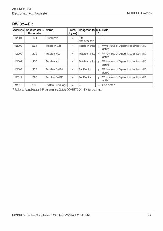
RW 32—Bit Address AquaMaster 3
Parameter Name Size
(bytes) Range/Units MID
? Note
12001 171 PressureId 4 0 to 999,999,999
— —
12003 224 TotaliserFwd 4 Totaliser units y Write value of 0 permitted unless MID active
12005 225 TotaliserRev 4 Totaliser units y Write value of 0 permitted unless MID active
12007 226 TotaliserNet 4 Totaliser units y Write value of 0 permitted unless MID active
12009 227 TotaliserTariffA 4 Tariff units y Write value of 0 permitted unless MID active
12011 228 TotaliserTariffB 4 Tariff units y Write value of 0 permitted unless MID active
12013 290 SystemErrorFlags 4 — — See Note 1 1 Refer to AquaMaster 3 Programming Guide COI/FET2XX—EN for settings.

AquaMaster 3 Electromagnetic flowmeter
MODBUS Tables Supplement COI/FET2XX/MOD/TBL-EN 23
MODBUS Protocol
RW Float Address AquaMaster
3 Parameter
Name Size (bytes)
Range/Units MID ?
Note
13001 005 EmptyPipeCal 4 — y —
13003 025 UserFlowSensorCal 4 — y User-defined flow sensor span
13005 030 ProfileFactor 4 — — Insertion probe profile factor
13007 031 InsertionFactor 4 — — Insertion probe insertion factor
13009 032 ProbePipeBore 4 mm — Insertion probe pipe bore
13011 038 CustomTotaliserUnits 4 per m3 y —
13013 068 PulsesPerPulseOutputUnit 4 — — —
13015 110 CustomVelocityUnits 4 per ms—1 — —
13017 113 CustomFlowUnits 4 per m3s—1 — —
13019 115 FlowUpperRange 4 Flow units y —
13021 116 FlowLowerRange 4 Flow units y —
13023 120 CustomPressureUnits 4 per mmHg — —
13025 122 PressureUpperRange 4 Pressure units
— —
13027 123 PressureLowerRange 4 Pressure units
— —
13029 178 PressureFactoryFSDBar 4 Bar — —
13031 179 PressureFactoryFSDVolts 4 V — —
13033 180 PressureFactoryZeroVolts 4 V — —
13035 193 UserPressureSpan 4 — — User span adjustment (dimensionless)
13037 194 UserPressureZero 4 mBar — User zero adjustment
13039 231 ExternalPowerUsageDays 4 days — —
13041 232 InternalPowerUsageDays 4 days — —
13043 256 FlowResponseTime 4 s y —
13045 257 PressureResponseTime 4 s — —
13047 345 ABB Reserved 4 — y —
13049 346 ABB Reserved 4 — y —

AquaMaster 3 Electromagnetic flowmeter
MODBUS Tables Supplement COI/FET2XX/MOD/TBL-EN 24
MODBUS Protocol
Tables of Settings 0 Special
1 N/A
2 PFA
3 PTFE
4 FEP
5 ABR
6 Rubber (WRC)
7 Polyurethane
8 HT Rubber
9 Polypropylene
10 PES
11 P E
12 PPS
13 Viton
14 St St
15 C St
16 Brass
17 Gold
18 Titanium
19 Hast B
20 Hast C
21 Plat
22 Tant
23 ?
Table A.1 Materials
0 N/A
1 Class1
2 Class2
3 MID Class1
4 MID Class2
Table A.2 Calibration Types
AquaMaster 3 Electromagnetic flowmeter
MODBUS Tables Supplement COI/FET2XX/MOD/TBL-EN 25
MODBUS Protocol
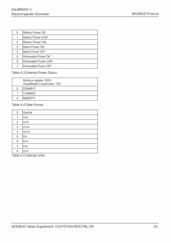
0 Battery Power OK
1 Battery Power LOW
2 Battery Power FAIL
3 Mains Power ON
4 Mains Power OFF
5 Renewable Power OK
6 Renewable Power LOW
7 Renewable Power OFF
Table A.3 External Power Status
Modbus register: 8030 AquaMaster 3 parameter: 159
0 DDMMYY
1 YYMMDD
2 MMDDYY
Table A.4 Date Format
Table A.5 Velocity Units
0 Special
1 m/s
2 m/m
3 cm/s
4 cm/m
5 ft/s
6 ft/m
7 in/s
8 in/m

AquaMaster 3 Electromagnetic flowmeter
MODBUS Tables Supplement COI/FET2XX/MOD/TBL-EN 26
MODBUS Protocol
Notes

AquaMaster 3 Electromagnetic flowmeter
MODBUS Tables Supplement COI/FET2XX/MOD/TBL-EN 27
MODBUS Protocol

AquaMaster 3 Electromagnetic flowmeter
MODBUS Tables Supplement COI/FET2XX/MOD/TBL-EN 28
MODBUS Protocol

Products and customer support
Automation SystemsFor the following industries:— Chemical & Pharmaceutical— Food & Beverage— Manufacturing— Metals and Minerals— Oil, Gas & Petrochemical— Pulp and Paper
Drives and Motors— AC and 6 Drives, AC and DC Machines, AC Motors to
1kV— Drive Systems— Force Measurement— Servo Drives
Controllers & Recorders— Single and Multi-loop Controllers— Circular Chart and Strip Chart Recorders— Paperless Recorders— Process Indicators
Flexible Automation— Industrial Robots and Robot Systems
Flow Measurement— Electromagnetic Flowmeters— Mass Flowmeters— Turbine Flowmeters— Wedge Flow Elements
Marine Systems & Turbochargers— Electrical Systems— Marine Equipment— Offshore Retrofit and Refurbishment
Process Analytics— Process Gas Analysis— Systems Integration
Transmitters— Pressure— Temperature— Level— Interface Modules
Valves, Actuators and Positioners— Control Valves— Actuators— Positioners
Water, Gas & Industrial Analytics Instrumentation— pH, Conductivity and Dissolved Oxygen Transmitters
and Sensors— Ammonia, Nitrate, Phosphate, Silica, Sodium,
Chloride, Fluoride, Dissolved Oxygen and Hydrazine Analyzers
— Zirconia Oxygen Analyzers, Katharometers, Hydrogen Purity and Purge-gas Monitors, Thermal Conductivity
Customer supportWe provide a comprehensive after sales service via a Worldwide Service Organization. Contact one of the following offices for details on your nearest Service and Repair Centre.
UKABB LimitedTel: +44 (0)1453 826661Fax: +44 (0)1453 829671
USAABB Inc.Tel: +1 215 674 6000Fax: +1 215 674 7183
Client WarrantyPrior to installation, the equipment referred to in this manual must be stored in a clean, dry environment, in accordance with the Company's published specification.Periodic checks must be made on the equipment's condition. In the event of a failure under warranty, the following documentation must be provided as substantiation:— A listing evidencing process operation and alarm
logs at time of failure.— Copies of all storage, installation, operating and
maintenance records relating to the alleged faulty unit.

Contact us
CO
I/FE
T2XX
/MO
D/T
BL–
EN
12.2
010
ABB LimitedProcess AutomationOldends LaneStonehouseGloucestershire GL10 3TAUKTel: +44 1453 826 661Fax: +44 1453 829 671
ABB Inc.Process Automation125 E. County Line RoadWarminsterPA 18974USATel: +1 215 674 6000Fax: +1 215 674 7183
www.abb.com
NoteWe reserve the right to make technical changes or modify the contents of this document without prior notice. With regard to purchase orders, the agreed particulars shall prevail. ABB does not accept any responsibility whatsoever for potential errors or possible lack of information in this document.
We reserve all rights in this document and in the subject matter and illustrations contained therein. Any reproduction, disclosure to third parties or utilization of its contents in whole or in parts – is forbidden without prior written consent of ABB.
Copyright© 2010 ABBAll rights reserved
3KXF208203R4501
MODBUS is a registered trademark of the Modbus-IDA organization
Top Related