


Languages
Pages
Legal


Digital Modulation and Detection
Mobile CommunicationsDigital Modulation and Detection
Wen-Shen Wuen
Trans. Wireless Technology LaboratoryNational Chiao Tung University
WS Wuen Mobile Communications 1
Outline Digital Modulation and Detection
Outline
1 Structure of Wireless Communication Link
2 Analog Modulation TechniquesAnalog Modulation Techniques
3 Digital Modulation TechniquesIntroductionLine CodingPulse ShapingGeometric Representation of Modulation Signals
4 Linear Modulations
5 Constant Envelope Modulation
6 Combined Linear and Contstant Envelope Modulation Techniques
WS Wuen Mobile Communications 2
Structure of Wireless Communication Link Digital Modulation and Detection
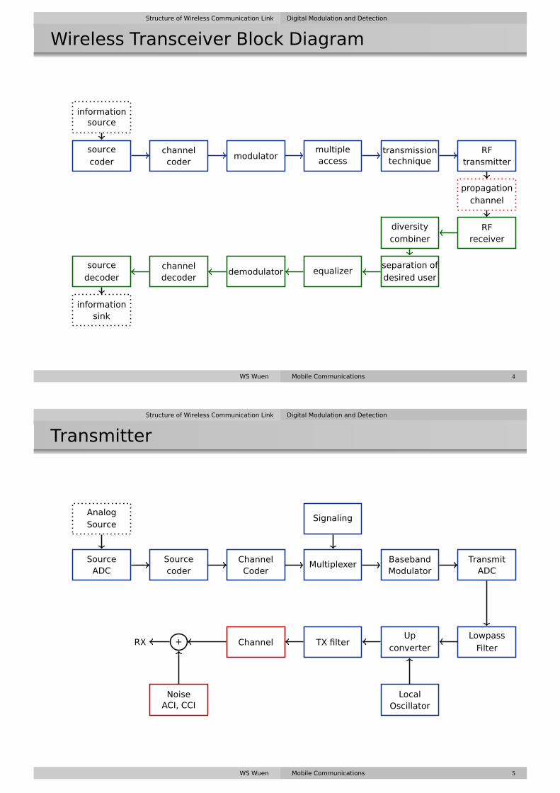
Wireless Transceiver Block Diagram
informationsource
source
coderchannelcoder
modulatormultipleaccess
transmissiontechnique
RFtransmitter
propagationchannel
RFreceiver
diversitycombiner
separation ofdesired user
equalizerdemodulatorchanneldecoder
source
decoder
informationsink
WS Wuen Mobile Communications 4
Structure of Wireless Communication Link Digital Modulation and Detection
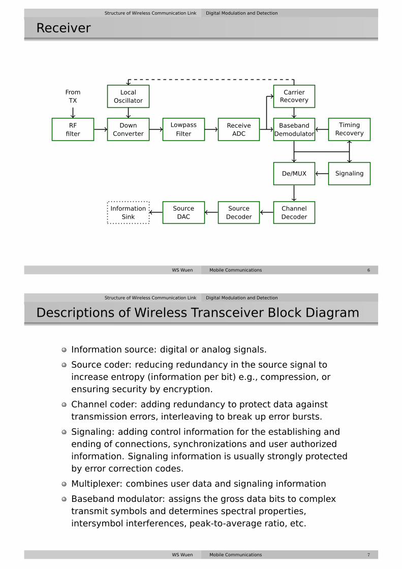
Transmitter
+RX
AnalogSource
SourceADC
Sourcecoder
ChannelCoder
Multiplexer
Signaling
BasebandModulator
TransmitADC
Lowpass
Filter
Upconverter
LocalOscillator
TX filterChannel
NoiseACI, CCI
WS Wuen Mobile Communications 5
Structure of Wireless Communication Link Digital Modulation and Detection
Receiver
FromTX
RFfilter
DownConverter
Lowpass
FilterReceiveADC
CarrierRecovery
BasebandDemodulator
De/MUX
TimingRecovery
Signaling
ChannelDecoder
SourceDecoder
LocalOscillator
SourceDAC
InformationSink
WS Wuen Mobile Communications 6
Structure of Wireless Communication Link Digital Modulation and Detection
Descriptions of Wireless Transceiver Block Diagram
Information source: digital or analog signals.
Source coder: reducing redundancy in the source signal toincrease entropy (information per bit) e.g., compression, orensuring security by encryption.
Channel coder: adding redundancy to protect data againsttransmission errors, interleaving to break up error bursts.
Signaling: adding control information for the establishing andending of connections, synchronizations and user authorizedinformation. Signaling information is usually strongly protectedby error correction codes.
Multiplexer: combines user data and signaling information
Baseband modulator: assigns the gross data bits to complextransmit symbols and determines spectral properties,intersymbol interferences, peak-to-average ratio, etc.
WS Wuen Mobile Communications 7

Structure of Wireless Communication Link Digital Modulation and Detection
Descriptions of Wireless Transceiver Block Diagram,
cont’d
Carrier recovery: determines the frequency and phase of thecarrier of the received signal.
Baseband demodulator: obtains soft-decision data fromdigitized baseband data and may also include equaliztion.
Symbol timing recovery: uses demodulated data to determinean estimate of the duration of symbols and use it to fine tunesampling intervals.
Decoders: use soft estimates from the demodulator to find theoriginal digital source data. Recent RX may perform jointdemodulation and decoding.
Demultiplexer: separates the user data and signalinginformation.
WS Wuen Mobile Communications 8
Analog Modulation Techniques Digital Modulation and Detection
Introduction
Modulation
The process by which some characteristic of a carrier wave isvaried in accordance with an information-bearing signal.
Modulating signal: information bearing signal
Modulated signal: the output of the modulation process
Linear modulation: if the input-output relation of the modulatorsatisfies the principle of superposition.
Benefits of modulation
Modulation used to shift the spectral content of a messagesignal so that it lies inside the operating frequency band of thewireless communication channel.
Modulation provides a mechanism for putting the informationcontent of a message signal into a form that may be lessvulnerable to noise or interference.
Modulation permits the use of multiple access.
WS Wuen Mobile Communications 10

Analog Modulation Techniques Digital Modulation and Detection
Introduction, cont’d
Analog and Digital Modulation Techniques
Analog modulation: m(t) and s(t) are continuous function oftime
Digital modulation: mapping of data bits to signal waveformsthat can be transmitted over an analog channel.
modulatorm(t) s(t)
Sinusoidal
Inputmodulating
signal
Outputmodulated
signal
carrierc(t)
WS Wuen Mobile Communications 11
Analog Modulation Techniques Digital Modulation and Detection
Amplitude and Angle Modulation
Amplitude modulation, AMthe amplitude of the carrier, A(t), is varied with linearly with themessage signal m(t)
Angle modulationthe angle of the carrier,
φ(t) = 2πfct +θ
is varied linearly with the message signal m(t)
Frequency Modulation, FMthe frequency of the carrier is varied linearly with the messagesignal m(t)Phase Modulation, PMthe phase of the carrier θ is varied linearly with the messagesignal m(t)
WS Wuen Mobile Communications 12

Analog Modulation Techniques Digital Modulation and Detection
Amplitude Modulation
AM signal
sAM (t) = Ac (1+m(t))cos(2πfct
)=Re{
g(t)ej2πfct}
where g(t) = Ac (1+m(t))Modulation index: the ratio of peak message signal amplitudeto the peak carrier amplitude.If m(t) = Am
Accos
(2πfmt
), k = Am
Ac
Spectrum of AM signal
SAM (f ) = 1
2Ac
(δ
(f − fc
)+M(f − fc
)+δ(f + fc
)+M(f + fc
))RF bandwidth of AM
BAM = 2fm
Total power of AM signal
PAM = 1
2A2
c (1+< m(t) >)2
if m(t) = k cos(2πfmt
)⇒ PAM = 12 A2
c
(1+ k2
2
)WS Wuen Mobile Communications 13
Analog Modulation Techniques Digital Modulation and Detection
Amplitude Modulation, cont’d
WS Wuen Mobile Communications 14

Analog Modulation Techniques Digital Modulation and Detection
Amplitude Modulation, cont’d
WS Wuen Mobile Communications 15
Analog Modulation Techniques Digital Modulation and Detection
Angle Modulation
FM signal
sFM (t) = Ac cos[2πfct +θ(t)
]= Ac cos
[2πfct +2πkf
∫ t
−∞m(τ)dτ
]
if m(t) = Am cos(2πfmt
)⇒ sFM (t) = Ac cos[
2πfct + kf Am
fmsin
(2πfmt
)]Frequency modulation index βf : defines the relation betweenthe message amplitude and the bandwidth of the transmittedsignal.
βf =kf Am
W= ∆f
W
PM signalsPM (t) = Ac cos
[2πfct +kθm(t)
]Phase modulation index βp
βp = kθAm =∆θ
WS Wuen Mobile Communications 16

Analog Modulation Techniques Digital Modulation and Detection
FM Demodulation: Slope Detection
v1(t) = V1 cos[2πfct +θ(t)
]= V1 cos
[2πfct +2πkf
∫ t
−∞m(τ)dτ
]v2(t) =−V1
[2πfct + dθ
dt
]sin
(2πfct +θ(t)
)vout (t) = V1
[2πfct + dθ
dt
]= V12πfc +V12πkf m(t)
WS Wuen Mobile Communications 17
Analog Modulation Techniques Digital Modulation and Detection
FM Demodulation: Quadrature Detection
WS Wuen Mobile Communications 18

Analog Modulation Techniques Digital Modulation and Detection
FM Demodulation: Zero-Crossing
WS Wuen Mobile Communications 19
Analog Modulation Techniques Digital Modulation and Detection
Bandwidth of FM Signals
Carson’s rule
An FM signal has 98% of the total transmitted power in a RFbandwidth BT is
BT = 2(βf +1
)fm (Upper bound)
BT = 2∆f (Lower bound)
Carson’s rule: for small values of modulation index (βf < 1), thespectrum of an FM wave is effectively limited to the carrierfrequency, and one pair of sideband frequencies at fc ± fm. Forlarge values of modulation index, the bandwidth approachesand is only slightly greater than 2∆f .
WS Wuen Mobile Communications 20

Analog Modulation Techniques Digital Modulation and Detection
Tradeoff Between SNR and Bandwidth in FM
SNR at the output of an FM receiver
SNRout = 6(βf +1
)β2
f
(m(t)
Vp
)2
SNRin
SNR at the input of an FM receiver
SNRin,FM = A2c /2
2N0(βf +1
)B
SNR at the input of an AM receiver
SNRin,AM = A2c
2N0B
for m(t) = Am sinωmt
SNRout = 3β2f
(βf +1
)SNRin,FM = 3β2
f SNRin,AM
FM offers excellent performance for fading signals.
WS Wuen Mobile Communications 21
Analog Modulation Techniques Digital Modulation and Detection
Example 1
How much bandwidth is required for an analog frequencymodulated signal that has an audio bandwidth of 5 kHz and amodulation index of three? How much output SNR improvementwould be obtained if the modulation index is increased to five?What is the tradeoff bandwidth for the improvement?Solution:BT = 2
(βf +1
)fm = 2(3+1)5 = 40 kHz.
The output SNR improvement factor is 3β2f (βf +1)
βf = 3 ⇒ 3 ·32(3+1) = 108 = 20.33 dB.βf = 5 ⇒ 3 ·52(5+1) = 450 = 26.53 dB. The improvement of output SNRis 26.53−20.33 = 6.2 dB. For βf = 5, the required bandwidth is 60 kHz.
WS Wuen Mobile Communications 22

Digital Modulation Techniques Digital Modulation and Detection
Digital Modulation Techniques
Advantages of Digital Modulation
greater noise immunity
robustness to channel impairments
easier multiplexing of various forms of information
greater security
Factors that influence the choice of digital modulation
Bandwidth efficiency
Adjacent channel interference
Sensitivity with respect to noise
Robustness with respect to delay and Doppler dispersion
Easy and cost-effective to implement
WS Wuen Mobile Communications 24
Digital Modulation Techniques Digital Modulation and Detection
Power Efficiency and Bandwidth Efficiency
Power efficiency (Energy efficiency), ηp
The ability of a modulation technique to preserve the fidelity ofthe digital message at low power levels.
Expressed as the ratio of the signal energy per bit to noisepower spectral density (Eb/N0) required at the receiver input fora certain probability of error.
Bandwidth efficiency, ηB
The ability of a modulation scheme to accommodate datawithin a limited bandwidth.
Defined as the ratio of the throughput data rate per Hertz in agiven bandwidth.
ηB = R
Bbps/Hz
WS Wuen Mobile Communications 25

Digital Modulation Techniques Digital Modulation and Detection
Shannon’s Channel Capacity Theorem
For an arbitrary small probability of error, the maximum possiblebandwidth efficiency is limited by the noise in the channel,
ηB,max = C
B= log2
(1+ S
N
)whereC is the channel capacity in bps,B is the RF bandwidth, andSN is the signal to noise ratio.
WS Wuen Mobile Communications 26
Digital Modulation Techniques Digital Modulation and Detection
Example 2
If the SNR of a wireless communication link is 20 dB and the RF bandwidthis 30 kHz, determine the maximum theoretical data rate that can betransmitted.Solution:SNR=20 dB=100, Bandwidth B=30000 Hz,C = B log2 (1+S/N) = 30000log2(1+100) = 199.75 kbps
Example 3
What is the theoretical maximum data rate that can be supported in a200 kHz channel for SNR=10 dB and 30 dB? How does this compare to theGSM standard?Solution:SNR=10 dB=10, B=200 kHz,C = B log2 (1+S/N) = 200000log2(1+10) = 691.886 kbpsGSM data rate is 270.833 kbps, which is about 40 % of the theoretical limitfor 10 dB SNR conditions.For SNR=30 dB=1000, B=200 kHz,C = B log2 (1+S/N) = 200000log2(1+1000) = 1.99 Mbps
WS Wuen Mobile Communications 27

Digital Modulation Techniques Digital Modulation and Detection
Bandwidth and Power Spectral Density of Digital
Signals
Various bandwidth definitions are based on the power spectraldensity of the signal.
Power spectral density (PSD) of a random signal w(t)
Pw(f ) = limT→∞
∣∣WT (f )∣∣2
T
where WT (f ) is the Fourier transform of wT (t) which is thetruncated version of the signal w(t)
wT (t) ={
w(t) −T/2 < t < T/20 otherwise
Power spectral density of a modulated (bandpass) signals(t) =Re
{g(t)ej2πfct
}Ps(f ) = 1
4
[Pg (f − fc)+Pg (−f − fc)
]where Pg (f ) is the PSD of g(t).
WS Wuen Mobile Communications 28
Digital Modulation Techniques Digital Modulation and Detection
Bandwidth and Power Spectral Density of Digital
Signals, cont’d
Absolute bandwidth: the range of frequencies over which thesignal has a non-zero power spectral density.
Null-to-null bandwidth: the width of the main spectral lobe
Half-power bandwidth (3-dB bandwidth): the interval betweenfrequencies at which the PSD has dropped to half power
Occupied bandwidth (FCC): the band which leaves exactly 0.5%of the signal above the upper band limit and exactly 0.5% ofthe signal power below the lower band limit, i.e. 99% of thesignal power is contained within the occupied bandwidth
WS Wuen Mobile Communications 29

Digital Modulation Techniques Digital Modulation and Detection
Line Coding
Mapping of binary information sequence into the digital signal thatenters the channel.
WS Wuen Mobile Communications 30
Digital Modulation Techniques Digital Modulation and Detection
Properties of Line Codes
Self-Synchronization There is enough timing informationbuilt into the code so that bit synchronizers can extract thetiming or clock signal.
Low Probability of Bit Error Receivers can be designed thatwill recover the binary data with a low probability of bit errorwhen the input data is corrupted by noise or ISI.
A Spectrum that is Suitable for the Channel For example,if the channel is AC coupled, the PSD of the line code signalshould not have DC component. In addition, the signalbandwidth needs to be sufficiently small compared to thechannel bandwidth, so that ISI will not be a problem.
Transmission Bandwidth This should be as small as possible.
Error Detection Capability It should be possible toimplement this feature easily by the addition of channelencoders and decoders, or the feature should be incorporatedinto the line code.
WS Wuen Mobile Communications 31

Digital Modulation Techniques Digital Modulation and Detection
Power Spectral Density of Line Codes
WS Wuen Mobile Communications 32
Digital Modulation Techniques Digital Modulation and Detection
The Need for Pulse Shaping
The most simple basis pulse is a rectangular pulse with duration T .
gR(t,T) ={
1 0 ≤ t ≤ T0 otherwise
GR(f ,T) = F{gR(t,T)
}= Tsinc(πfT
)e−jπfT
where sinc(x) = sin(x)/x.
When rectangular pulses are passed through a bandlimitedchannel, the pulses will spread in time, and the pulse for eachsymbol will smear into time intervals of succeeding symbols. ⇒inter-symbol interference (ISI)
In frequency domain the rectangular pulse creates largeadjacent channel interference. ⇒ the transmitting pulse shouldbe shaped to limit the bandwidth as well as to minimize ISI.
WS Wuen Mobile Communications 33

Digital Modulation Techniques Digital Modulation and Detection
Nyquist Criterion for ISI Cancellation
The effect of ISI could be completely nullified if the overall responseof the communication system is designed so that at every samplinginstant at the receiver, the response due to all symbols except thecurrent symbol is equal to zero.
Impulse response of the overall communication system, heff (t)
heff (nTs) ={
K n = 00 n 6= 0
heff (t) = δ(t)∗p(t)∗hc(t)∗hr(t)
heff (t) should have a fast decay with a small magnitude nearthe sample values for n 6= 0
WS Wuen Mobile Communications 34
Digital Modulation Techniques Digital Modulation and Detection
Nyquist Ideal Pulse Shaping
heff (t) =sin
(πtTs
)πtTs
= sinc
(πt
Ts
),Heff (f ) = 1
fsrect
(f
fs
)where fs is the symbol rate.Ideal Nyquist pulse shaping filter is difficult to implement
Noncausal system (heff (t) exists for t < 0) and is difficult toapproximate
Sensitive to jitter (error in sampling time of zero-crossings willcause significant ISI)
WS Wuen Mobile Communications 35

Digital Modulation Techniques Digital Modulation and Detection
Nyquist Filter
Nyquist proved that any filter with a transfer function having arectangular filter of bandwidth f0 ≥ 1/2Ts, convolved with anyarbitrary even function Z(f ) with zero magnitude outside thepassband, satisfied the zero ISI condition.
Heff (f ) = rect
(f
f0
)∗Z(f )
where Z(f ) = Z(−f ) and Z(f ) = 0 for |f | ≥ f0 ≥ 1/2Ts.
Nyquist criterion
Any filter with an impulse response
heff (t) = sin(πt/Ts)
πtz(t)
can achieve ISI cancellation. Filters which satisfies the Nyquistcriterion are called Nyquist filters.
WS Wuen Mobile Communications 36
Digital Modulation Techniques Digital Modulation and Detection
Nyquist Filter, cont’d
Heff is often achieved by using filters with transfer function√
Heff atboth the transmitter and receiver.⇒ providing a matched filter response for the system while at thesame time minimizing the bandwidth and ISI.
WS Wuen Mobile Communications 37

Digital Modulation Techniques Digital Modulation and Detection
Raised Cosine Rolloff Filter
HRC (f ) =
1 0 ≤ |f | ≤ 1−α
2Ts12
[1+cos
(π(2|f |Ts−1+α)
2α
)]1−α2Ts
≤ |f | ≤ 1+α2Ts
0 |f | > 1+α2Ts
where α is the rolloff factor which ranges between 0 and 1.
WS Wuen Mobile Communications 38
Digital Modulation Techniques Digital Modulation and Detection
Raised Cosine Rolloff Filter, cont’d
hRC (t) =sin
(πtTs
)πt
cos(παtTs
)1−
(4αt2Ts
)2
The symbol rate Rs that can be passed through a baseband raisedcosine rolloff filter is
Rs = 1
Ts= 2B
1+αwhere B is the absolute filter bandwidth.
WS Wuen Mobile Communications 39
Digital Modulation Techniques Digital Modulation and Detection
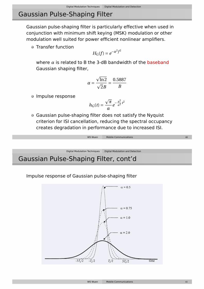
Gaussian Pulse-Shaping Filter
Gaussian pulse-shaping filter is particularly effective when used inconjunction with minimum shift keying (MSK) modulation or othermodulation well suited for power efficient nonlinear amplifiers.
Transfer functionHG(f ) = e−α
2f 2
where α is related to B the 3-dB bandwidth of the basebandGaussian shaping filter,
α=p
ln2p2B
= 0.5887
B
Impulse response
hG(t) =pπ
αe−
π2
α2 t2
Gaussian pulse-shaping filter does not satisfy the Nyquistcriterion for ISI cancellation, reducing the spectral occupancycreates degradation in performance due to increased ISI.
WS Wuen Mobile Communications 40
Digital Modulation Techniques Digital Modulation and Detection
Gaussian Pulse-Shaping Filter, cont’d
Impulse response of Gaussian pulse-shaping filter
WS Wuen Mobile Communications 41

Digital Modulation Techniques Digital Modulation and Detection
Example 4
Find the first zero-crossing RF bandwidth of a rectangular pulsewhich has Ts = 41.06 µs. Compare this to the bandwidth of a raisedcosine filter pulse with Ts = 41.06 µs and α= 0.35.Solution:The first zero-crossing filter (null-to-null) bandwidth of a rectangularpulse is equal to
2
Ts= 2
41.06×10−6= 48.71 kHz
and that for a raised cosine filter with α= 0.35 is
1
Ts(1+α) = 1
41.06×10⁻⁶(1+0.35) = 32.88 kHz
WS Wuen Mobile Communications 42
Digital Modulation Techniques Digital Modulation and Detection
Geometric Representation of Modulation Signals
M-ary modulation signals
Choosing a particular signal waveform si(t) from a finite set ofpossible signal waveforms (or symbols) based on theinformation bits applied to the modulator.
S = {s1(t),s2(t), . . . ,sM (t)}
where M represents a total of M possible signals in themodulation set S. ⇒ a maximum of log2 M bits of informationper symbol.
Represent the modulation signals on a vector space with a setof N orthonormal signals that form a basis for the vector space.Any point in the vector space can be represented as a linearcombination of the basis signals.
WS Wuen Mobile Communications 43

Digital Modulation Techniques Digital Modulation and Detection
Signal Space for Modulation Signals
Basis {φ1(t),φ2(t), . . . ,φN (t)
}Modulation Signals
si(t) =N∑
j=1sijφj(t).
Basis signals are orthogonal to one another in time∫ ∞
−∞φi(t)φj(t)dt = 0 i 6= j
Each basis signal is normalized to have unit energy
E =∫ ∞
−∞φ2
i (t)dt = 1
WS Wuen Mobile Communications 44
Digital Modulation Techniques Digital Modulation and Detection
Signal-Space for Digital Modulation
Consider two-dimensional signal constellations, the normalizedbasis of unite energy are φ1(t) and φ2(t)
φ1(t) =√
2
Tcos(2πfct), 0 ≤ t ≤ T
φ2(t) =√
2
Tsin(2πfct), 0 ≤ t ≤ T
where ∫ T
0φ1(t)φ2(t)dt = 0
and ∫ T
0φ2
1(t)dt =∫ T
0φ2
2(t)dt = 1
si(t) = si1φ1(t)+ si2φ2(t) or si = (si1,si2)
||si −sk|| =√√√√ N∑
j=1
(sij − skj
)2 =√∫ T
0(si(t)− sk(t))2 dt
WS Wuen Mobile Communications 45

Digital Modulation Techniques Digital Modulation and Detection
Example: BPSK Signals
s1(t) =√
2Eb
Tbcos(2πfct), 0 ≤ t ≤ Tb
s2(t) =−√
2Eb
Tbcos(2πfct), 0 ≤ t ≤ Tb
where Eb is the energy per bit, Tb is the bit period, and a rectangularpulse p(t) = rect((t −Tb/2)/Tb) is assumed.
φ1(t) =√
2
Tbcos(2πfct), 0 ≤ t ≤ Tb
BPSK signal set
SBPSK ={√
Ebφ1(t),−√
Ebφ1(t)}
WS Wuen Mobile Communications 46
Digital Modulation Techniques Digital Modulation and Detection
Constellation
WS Wuen Mobile Communications 47

Digital Modulation Techniques Digital Modulation and Detection
Error Probability
Upper bound for the probability of symbol error in an additive whiteGaussian noise channel (AWGN) with a noise density N0 for anarbitrary constellation
The average probability of error for a particular modulationsignal
Ps(ε|si) ≤∑
j=1,j 6=iQ
(dijp2N0
)where dij is the Euclidean distance between the i-th and j-thsignal point in the constellation.
If all the M modulation waveforms are equally likely to betransmitted, the average probability of error for a modulation
Ps(ε) = 1
M
M∑i=1
Ps(ε|si)P(si) = 1
M
M∑i=1
Ps(ε|si)
WS Wuen Mobile Communications 48
Linear Modulations Digital Modulation and Detection
Binary Phase Shift Keying (BPSK)
sinusoidal carrier amplitude Ac, Energy per bit Eb = 12 A2
c Tb
sBPSK (t) =√
2Eb
Tbcos(2πfct +θc) for binary 1
sBPSK (t) =−√
2Eb
Tbcos(2πfct +θc) for binary 0
or
sBPSK (t) = m(t)
√2Eb
Tbcos(2πfct +θc)
orsBPSK (t) =Re
{gBPSK (t)ej2πfct
}where
gBPSK (t) =√
2Eb
Tbm(t)ejθc
WS Wuen Mobile Communications 50

Linear Modulations Digital Modulation and Detection
Spectrum and BPSK Bandwidth
Power spectral density of the complex envelope gBPSK (t)
PgBPSK (f ) = 2Eb
(sinπfTb
πfTb
)2
PSD of a BPSK signal at RF
PBPSK (f ) = Eb
2
[(sinπ(f − fc)Tb
π(f − fc)Tb
)2
+(
sinπ(−f − fc)Tb
π(−f − fc)Tb
)2]
WS Wuen Mobile Communications 51
Linear Modulations Digital Modulation and Detection
BPSK Receiver
If no multipath impairments are introduced by the channel, thereceived BPSK signal
rBPSK (t) = m(t)
√2Eb
Tbcos(2πfct +θc +θch) = m(t)
√2Eb
Tbcos(2πfct +θ)
The output of the multiplier after the frequency divider
m(t)
√2Eb
Tbcos2(2πfct +θ) = m(t)
√2Eb
Tb
[1
2+ 1
2cos(4πfct +2θ)
]Probability of bit error
Pe,BPSK = Q
(√2Eb
N0
)
WS Wuen Mobile Communications 52

Linear Modulations Digital Modulation and Detection
BPSK Receiver, cont’d
WS Wuen Mobile Communications 53
Linear Modulations Digital Modulation and Detection
Differential Phase Shift Keying (DPSK)
Noncoherent form of phase shift keying ⇒ avoids the need for acoherent reference signal at the receiver.Input binary sequence is first differentially encoded and thenmodulated using BPSK modulator.Differentially encode: dk = mk ⊕dk−1. Leave dk unchanged fromthe previous symbol if the incoming binary symbol mk is 1 andto toggle dk if mk is 0.
mk 1 0 0 1 0 1 1 0dk−1 1 1 0 1 1 0 0 0
dk 1 1 0 1 1 0 0 0 1
WS Wuen Mobile Communications 54

Linear Modulations Digital Modulation and Detection
Differential Phase Shift Keying (DPSK), cont’d
DPSK signaling has about 3 dB worst energy efficency thancoherent PSK.
Average probability of error for DPSK in AWGN channel is
Pe,DPSK = 1
2e− Eb
N0
WS Wuen Mobile Communications 55
Linear Modulations Digital Modulation and Detection
Quadrature Phase Shift Keying (QPSK)
QPSK has twice the bandwidth efficiency of BPSK, since two bits aretransmitted in a single modulation symbol.
SQPSK (t) =√
2Es
Tscos
[2πfct + (i−1)
π
2
],0 ≤ t ≤ Ts, i = 1,2,3,4
where Ts = 2Tb. or
SQPSK (t) =√
2Es
Tscos
[(i−1)
π
2
]cos(2πfct)−
√2Es
Tssin
[(i−1)
π
2
]sin(2πfct)
if φ1 =p
2/Ts cos(2πfct) and φ2 =p
2/Ts sin(2πfct) are defined over0 ≤ t ≤ Ts,
SQPSK (t) ={√
Es cos[
(i−1)π
2
]φ1(t)−
√Es sin
[(i−1)
π
2
]φ2(t)
}i = 1,2,3,4
WS Wuen Mobile Communications 56

Linear Modulations Digital Modulation and Detection
Quadrature Phase Shift Keying (QPSK), cont’d
The average probability of bit error in the AWGN channel is
Pe,QPSK = Q
( p2Esp2N0
)= Q
(√2Eb
N0
)
WS Wuen Mobile Communications 57
Linear Modulations Digital Modulation and Detection
QPSK Power Spectral Density
The PSD of a QPSK signal using rectangular pulses can be expressedas
PQPSK (f ) = Es
2
[(sinπ(f − fc)Ts
π(f − fc)Ts
)2
+(
sinπ(−f − fc)Ts
π(−f − fc)Ts
)2]or
PQPSK (f ) = Eb
[(sin2π(f − fc)Tb
2π(f − fc)Tb
)2
+(
sin2π(−f − fc)Tb
2π(−f − fc)Tb
)2]
WS Wuen Mobile Communications 58
Linear Modulations Digital Modulation and Detection
QPSK Transmission and Detection
QPSK Transmitter
WS Wuen Mobile Communications 59
Linear Modulations Digital Modulation and Detection
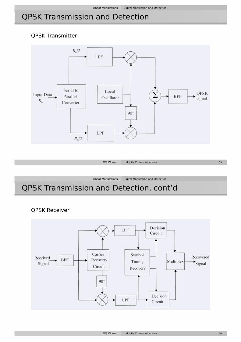
QPSK Transmission and Detection, cont’d
QPSK Receiver
WS Wuen Mobile Communications 60

Linear Modulations Digital Modulation and Detection
Offset QPSK
To ensure fewer baseband signal transitions applied to the RFamplifier ⇒ supports more efficient amplification and helpseliminate spectrum regrowthEven and odd bit streams, mI (t) and mQ(t) are offset in theirrelative alignment by one bit period (half-symbol period.)Only one of the two bit streams can change values ⇒ maximumphase shift of the signal is limited to ± 90◦
WS Wuen Mobile Communications 61
Linear Modulations Digital Modulation and Detection
QPSK v.s. Offset QPSK
WS Wuen Mobile Communications 62

Linear Modulations Digital Modulation and Detection
π/4 QPSK
Maximum phase change is limited to ± 135◦
Switching between two constellations, every successive bitensures that there is at least a phase shift nπ
4 for every symbol
WS Wuen Mobile Communications 63
Linear Modulations Digital Modulation and Detection
π/4 QPSK Transmission Techniques
Ik = cosθk = Ik−1 cosφk −Qk−1 sinφk
Qk = sinθk = Ik−1 sinφk +Qk−1 cosφk
where θk = θk−1 +φk.
sπ/4QPSK (t) = I(t)cos2πfct −Q(t)sin2πfct
where
I(t) =N−1∑k=0
Ikp(t −kTs −Ts/2) =N−1∑k=0
cosθkp(t −kTs −Ts/2)
Q(t) =N−1∑k=0
Qkp(t −kTs −Ts/2) =N−1∑k=0
sinθkp(t −kTs −Ts/2)
and the peak amplitude of I(t),Q(t) can take one of the five values{0,1,−1, 1p
2,− 1p
2
}WS Wuen Mobile Communications 64
Linear Modulations Digital Modulation and Detection
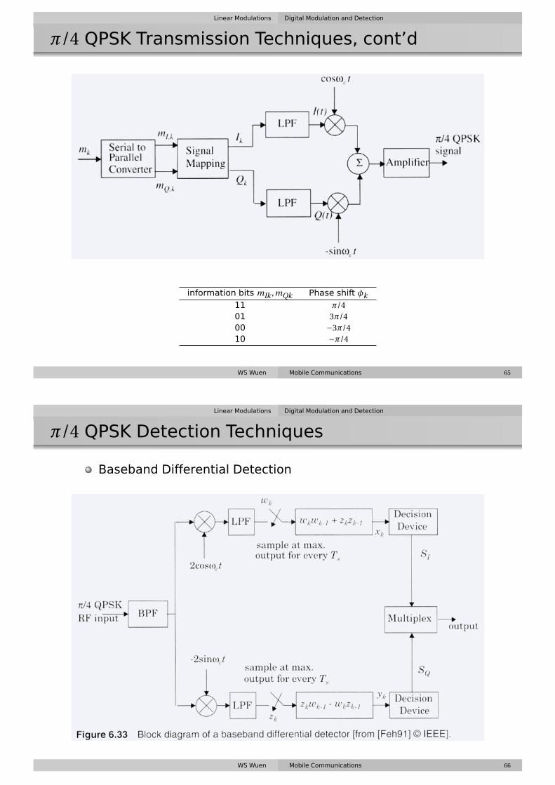
π/4 QPSK Transmission Techniques, cont’d
information bits mIk ,mQk Phase shift φk11 π/401 3π/400 −3π/410 −π/4
WS Wuen Mobile Communications 65
Linear Modulations Digital Modulation and Detection
π/4 QPSK Detection Techniques
Baseband Differential Detection
WS Wuen Mobile Communications 66

Linear Modulations Digital Modulation and Detection
π/4 QPSK Detection Techniques, cont’d
Baseband Differential Detection
wk = cos(φk −γ),zk = sin(φk −γ)
xk = wkwk−1 +zkzk−1,yk = zkwk−1 −wkzk−1
The output of differential decoder,
xk = cos(φk −γ)cos(φk−1 −γ)+ sin(φk −γ)sin(φk−1 −γ) = cos(φk −φk−1)
yk = sin(φk −γ)sin(φk−1 −γ)+cos(φk −γ)cos(φk−1 −γ) = sin(φk −φk−1)
The output of the decision device,
SI = 1, if xk > 0 or SI = 0, if xk < 0
SQ = 1, if yk > 0 or SQ = 0, if yk < 0
WS Wuen Mobile Communications 67
Linear Modulations Digital Modulation and Detection
π/4 QPSK Detection Techniques
IF Differential Detector
WS Wuen Mobile Communications 68

Linear Modulations Digital Modulation and Detection
π/4 QPSK Detection Techniques
FM Discriminator
WS Wuen Mobile Communications 69
Constant Envelope Modulation Digital Modulation and Detection
Nonlinear Modulation
Nonlinear modulation: the amplitude of the carrier is constant,regardless of the variation in the modulating signal
Advantages
Efficient power amplifier can be used ⇒ without introducingdegradation in the spectrum occupancy of the transmitted signal.Low out-of-band radiation of the order of −60 dB to −70 dB can beachieved.Limiter-discriminator detection can be used ⇒ simplifyingreceiver designs and providing high immunity against random FMnoise and signal fluctuation due to Rayleigh fading.
WS Wuen Mobile Communications 71

Constant Envelope Modulation Digital Modulation and Detection
Binary Frequency Shift Keying (BFSK)
sFSK (t) = vH (t) =√
2Eb
Tbcos
(2πfc +2π∆f
)t, 0 ≤ t ≤ Tb (binary 1)
sFSK (t) = vL(t) =√
2Eb
Tbcos
(2πfc −2π∆f
)t, 0 ≤ t ≤ Tb (binary 0)
Discontinuous FSK
sFSK (t) = vH (t) =√
2Eb
Tbcos
(2πfH t +θ1
), 0 ≤ t ≤ Tb (binary 1)
sFSK (t) = vL(t) =√
2Eb
Tbcos
(2πfLt +θ2
), 0 ≤ t ≤ Tb (binary 0)
Continuous FSK
sFSK (t) =√
2Eb
Tbcos
(2πfct +θ(t)
)=√2Eb
Tbcos
(2πfct +2πkf
∫ t
−∞m(τ)dτ
)WS Wuen Mobile Communications 72
Constant Envelope Modulation Digital Modulation and Detection
BPSK, cont’d
Transmission bandwidth BT of an FSK signal BT = 2∆f +2B
Rectangular pulses is B = R ⇒ BT = 2(∆f +R)
Raised cosine pulse-shaping filter BT = 2∆f + (1+α)R
Coherent Detection of Binary FSK
Pe,FSK = Q
(Eb
N0
)
WS Wuen Mobile Communications 73

Constant Envelope Modulation Digital Modulation and Detection
Noncoherent Detection of Binary FSK
Noncoherent Detection of Binary FSK
Pe,FSK ,NC = 1
2e− Eb
2N0
WS Wuen Mobile Communications 74
Constant Envelope Modulation Digital Modulation and Detection
Minimum Shift Keying (MSK)
A special type of continuous phase frequency shift keying(CPFSK) wherein the peak frequency deviation is equal to 1/4the bit rate.
Modulation index: kFSK = (2∆F)/Rb, where ∆F is the peak RFfrequency deviation and Rb is the bit rate.
Minimum shift keying: the minimum frequency separation (i.e.,bandwidth) that allows orthogonal detection.
MSK signal can be thought of as a special form of OQPSK wherethe base band rectangular pulses are replaced withhalf-sinusoidal pulses.
SMSK (t) =N−1∑i=0
mIi (t)p(t−2iTb)cos2πfct+N−1∑i=0
mQi (t)p(t−2iTb−Tb)sin2πfct
where
p(t) ={
cos(πt
2Tb
)0 ≤ t ≤ 2Tb
0 elsewhere
WS Wuen Mobile Communications 75

Constant Envelope Modulation Digital Modulation and Detection
Minimum Shift Keying (MSK), cont’d
MSK signal can be seen as a special type of a continuous phaseFSK
SMSK (t) =√
2Eb
Tbcos
[2πfct = mIi (t)mQi (t)
πt
2Tb+φk
]where phik is 0 or π depending on whether mIi (t) is 1 or −1.
Phase continuity at the bit transition period is ensured bychoosing the carrier frequency to be an integral multiple ofRb/4 = 1/(4T)
MSK signal is an FSK signal with binary signaling frequencies offc + 1
4T and fc − 14T .
MSK signal varies linearly during the course of each bit period.
WS Wuen Mobile Communications 76
Constant Envelope Modulation Digital Modulation and Detection
MSK Power Spectrum Density
The baseband pulse shaping function for MSK is
p(t) ={
cos(πt2T
) |t| < T0 elsewhere
PMSK (f ) = 16
π2
(cos2π(f + fc)T
1.16f 2T 2
)2
+ 16
π2
(cos2π(f − fc)T
1.16f 2T 2
)2
WS Wuen Mobile Communications 77

Constant Envelope Modulation Digital Modulation and Detection
MSK Transmitter
WS Wuen Mobile Communications 78
Constant Envelope Modulation Digital Modulation and Detection
MSK Receiver
WS Wuen Mobile Communications 79

Constant Envelope Modulation Digital Modulation and Detection
Gaussian Minimum Shift Keying (GMSK)
Passing the modulating NRZ data waveform through apremodulation Gaussian pulse-shaping filterConsiderably reducing the sidelobe levels in the transmittedspectrumExcellent power efficiency (due to the constant envelope) andspectrum efficiencyISI degradation is not sever if the 3-dB bandwidth bit durationproduct BT > 0.5.As long as GMSK irreducible error rate is less than thatproduced by the mobile channel, no penalty in using GMSK.
GMSK premodulation filter impulse response
hG(t) =pπ
αe−
π2
α2 t2
GMSK premodulation filter transfer function
HG(f ) = e−α2f 2
α=p
ln2p2B
= 0.5887
B
WS Wuen Mobile Communications 80
Constant Envelope Modulation Digital Modulation and Detection
Gaussian Minimum Shift Keying (GMSK), cont’d
GMSK bit error rate
Pe = Q
(√2γEb
N0
)where
γ'{
0.68 GMSK with BT = 0.250.85 MSK (BT =∞)
WS Wuen Mobile Communications 81

Constant Envelope Modulation Digital Modulation and Detection
GMSK Transmitter and Receiver
WS Wuen Mobile Communications 82
Constant Envelope Modulation Digital Modulation and Detection
Example 5
Find the 3-dB bandwidth for a Gaussian low pass filter used toproduce 0.25 GMSK with a channel data rate of Rb = 270 kbps. Whatis the 90% power bandwidth in the RF channel? Specify theGuassian filter parameter α.Solution:
T = 1
Rb= 1
270×103 = 3.7µs
∵ BT = 0.25 ∴ B = 0.25
T= 0.25
3.7×10−6 = 67.567kHz
RF bandwidth
BW = 0.57Rb = 0.57×270×103 = 153.9kHz
WS Wuen Mobile Communications 83

Combined Linear and Contstant Envelope Modulation Techniques Digital Modulation and Detection
M-ary Phase Shift Keying (MPSK)
The carrier phase takes on one of M possible values
θi = 2π(i−1)
M, i = 1,2, . . . ,M
MPSK signal waveform
si(t) =√
2Es
Tscos
(2πfct + 2π
M(i−1)
),0 ≤ t ≤ Ts, i = 1,2, . . . ,M
Es: Energy per symbol, Es = (log2 M)Eb
Ts: symbol period, Ts = (log2 M)Tb
MPSK in quadrature form
si(t) =√
2Es
Tscos
(2π
M(i−1)
)cos(2πfct)−
√2Es
Tssin
(2π
M(i−1)
)sin(2πfct)
Letφ1(t) =
√2/Ts cos(2πfct),φ2(t) =
√2/Ts sin(2πfct),
SMPSK (t) ={√
Es cos
(2π
M(i−1)
),−
√Es sin
(2π
M(i−1)
)}WS Wuen Mobile Communications 85
Combined Linear and Contstant Envelope Modulation Techniques Digital Modulation and Detection
Error Probability of M-ary PSK
Distance between adjacent symbols: 2p
Es sin(πM
)Average symbol error probability of an M-ary PSK is
Pe ≤ 2Q
(√2Eb log2 M
N0sin
( πM
))Average symbol error probability of a differential M-ary PSK inAWGN channel for M ≥ 4 is approximately
Pe ≈ 2Q
(√4Es
N0sin
( πM
))
WS Wuen Mobile Communications 86

Combined Linear and Contstant Envelope Modulation Techniques Digital Modulation and Detection
Power Spectra of M-ary PSK
PSD of the M-ary PSK signal with rectangular pulses is
PMPSK = Es
2
[(sinπ(f − fc)Ts
π(f − fc)Ts
)2
+(
sinπ(−f − fc)Ts
π(−f − fc)Ts
)2]
PMPSK = Eb log2 M
2
[(sinπ(f − fc)Tb log2 M
π(f − fc)Tb log2 M
)2
+(
sinπ(−f − fc)Tb log2 M
π(−f − fc)Tb log2 M
)2]
WS Wuen Mobile Communications 87
Combined Linear and Contstant Envelope Modulation Techniques Digital Modulation and Detection
Power Spectra of M-ary PSK, cont’d
WS Wuen Mobile Communications 88

Combined Linear and Contstant Envelope Modulation Techniques Digital Modulation and Detection
M-ary Quadrature Amplitude Modulation (QAM)
si(t) =√
2Emin
Tsai cos(2πfct)+
√2Emin
Tsbi sin(2πfct),
0 ≤ t ≤ T , i = 1,2, . . . ,M
where Emin is the energy of the signal with the lowest amplitude andthe coordinate of the ith point are ai
pEmin and bi
pEmin.
WS Wuen Mobile Communications 89
Combined Linear and Contstant Envelope Modulation Techniques Digital Modulation and Detection
M-ary Quadrature Amplitude Modulation, cont’d
(ai,bi) is an element of the L×L matrix
{ai,bi} =
(−L+1,L−1) (−L+3,L−1) · · · (L−1,L−1)(−L+1,L−3) (−L+3,L−3) · · · (L−1,L−3)
......
. . ....
(−L+1,−L+1) (−L+3,−L+1) · · · (L−1,−L+1)
where L =p
M
16-QAM: L =p16 = 4 4×4 matrix
{ai,bi} =
(−3,3) (−1,3) (1,3) (3,3)(−3,1) (−1,1) (1,1) (3,1)
(−3,−1) (−1,−1) (1,−1) (3,−1)(−3,−3) (−1,−3) (1,−3) (3,−3)
WS Wuen Mobile Communications 90

Combined Linear and Contstant Envelope Modulation Techniques Digital Modulation and Detection
M-ary QAM Error Probability
Average probability of error in AWGN channel for M-ary QAM,using coherent detection
Pe ≈ 4
(1− 1p
M
)Q
(√2Emin
N0
)
In terms of average signal energy Eav
Pe ≈ 4
(1− 1p
M
)Q
(√3Eav
(M −1)N0
)
WS Wuen Mobile Communications 91
Combined Linear and Contstant Envelope Modulation Techniques Digital Modulation and Detection
M-ary Frequency Shift Keying (MFSK)
M-ary FSK signal
si(t) =√
2Es
Tscos
[π
Ts(nc + i)t
]0 ≤ t ≤ Ts, i = 1,2, . . . ,M
where fc = nc/2Ts for some integer nc
The M transmitted signals are of equal energy and equalduration and the signal frequencies are separated by 1/2Ts Hz.For coherent M-ary FSK, the optimum receiver consists of abank of M correlators or matched filters tuned to the M distinctcarriers.⇒ Average probability of error
Pe ≤ (M −1)Q
(√Eb log2 M
N0
)For non-coherent detection using matched filters followed byenvelope detectors, the average probability of error
Pe =M−1∑k=1
((−1)k+1
k+1
(M −1
k
)e
−kEs(k+1)N0
)and using only the leading terms of the binomial expansion, theprobability of error is bounded as
Pe ≤ M −1
2e− Es
2N0
WS Wuen Mobile Communications 92

Combined Linear and Contstant Envelope Modulation Techniques Digital Modulation and Detection
M-ary Frequency Shift Keying (MFSK), cont’d
Channel bandwidth of a coherent M-ary FSK signal
B = Rb(M +3)
2log2 M
Channel bandwidth of a non-coherent M-ary FSK
B = RbM
2log2 M
WS Wuen Mobile Communications 93
Top Related