


Languages
Pages
Legal


Mixed Material Joining
Advancements and Challenges
Shashank Modi
Mark Stevens
Matt Chess
May
2017

For citations and reference to this publication, please use the following:
Modi, S., Stevens, M., & Chess, M. Mixed Material Joining Advancements and Challenges. Center for
Automotive Research, Ann Arbor, MI. May 2017.

ACKNOWLEDGEMENTS
The authors would like to thank the industry experts who contributed to this whitepaper. Their
willingness to share insights with the Center for Automotive Research (CAR) and provide thoughtful
feedback is greatly appreciated. We would like to especially thank the members of the CAR Coalition for
Automotive Lightweighting Materials (CALM) working group for their interest and support for
precompetitive collaborative research for advancing mixed-material joining technologies. We would like
to thank Dr. Manish Mehta for his contribution to this whitepaper. The authors would also like to thank
the CAR team, especially Dr. Jay Baron and Brian Esterberg for their guidance; Brett Smith, Dave Andrea,
and Lisa Hart for reviewing and editing this paper.
The organizations that contributed to this research include:
Vehicle Manufacturers Suppliers Organizations BMW AK Steel American Chemistry Council Fiat Chrysler Automobiles Altair Aluminum Association's Transportation Group Ford Motor Company Böllhoff General Motors Coldwater Machine Company Jaguar Land Rover Dow Automotive Toyota Motor Corporation DuPont
EJOT
Eastman Chemical Company
Faurecia
Henkel
Shiloh Industries
Shashank Modi Mark Stevens Matt Chess
3005 Boardwalk, Suite 200 Ann Arbor, MI 48108 www.cargroup.org CAR’s mission is to conduct independent research and analysis to educate, inform and advise
stakeholders, policy makers, and the general public on critical issues facing the automotive industry, and
the industry’s impact on the U.S. economy and society.

i | Page Center for Automotive Research © 2016
CONTENTS
I. INTRODUCTION AND METHOD ............................................................................................................. 1
II. MULTI-MATERIAL JOINING TECHNOLOGIES ......................................................................................... 2
III. PARAMETERS CONSIDERED FOR SELECTING JOINING TECHNOLOGIES ............................................... 9
IV. TEST PROCEDURES FOR EVALUATING JOINTS.................................................................................... 12
V. MAJOR CHALLENGES WITH MIXED-MATERIAL JOINING TECHNOLOGIES ......................................... 14
VI. FUTURE POTENTIAL WORK AND NEXT STEPS .................................................................................... 24
VII. SUMMARY AND THE WAY FORWARD ................................................................................................ 28
LIST OF FIGURES Figure 1: Example of a Multi-Material Design .............................................................................................. 2
Figure 2: Resistance Spot Welding Process .................................................................................................. 3
Figure 3: Friction Stir Spot Welding Process ................................................................................................. 4
Figure 4: Laser Brazing Process ..................................................................................................................... 4
Figure 5: a) Spin Welding Process ; b) Vibration Welding Process ............................................................... 5
Figure 6: Infrared Welding Process ............................................................................................................... 5
Figure 7: Self-Piercing Rivets Process ........................................................................................................... 6
Figure 8: Clinching Process............................................................................................................................ 6
Figure 9: One-Sided High Speed Nails Process ............................................................................................. 7
Figure 10: Property Range of Adhesives ....................................................................................................... 8
Figure 11: Magnetic Pulse Welding Process ................................................................................................. 8
Figure 12: Joining Technologies Commonly used for Different Material Combinations ............................. 9
Figure 13: Parameters OEMs Consider for Selecting Joining Technologies for a Body Shop ....................... 9
Figure 14: Basic Sheet Metal Joint Designs ................................................................................................. 10
Figure 15: Failure Modes in Bonded Joints ................................................................................................. 13
Figure 16: Common Adhesive Destructive Testing Methods ..................................................................... 13
Figure 17: Galvanic Series ........................................................................................................................... 15
Figure 18: Different Materials Expand Differently Under Thermal Load .................................................... 16
Figure 19:The Slotted Hole and Sliding Attachment at One End of the Plastic Cover in The Lower
Assembly Enables it to Accommodate The Thermal Expansion Difference With The Metal Base ............. 17
Figure 20: Stages in Making a Spot Weld .................................................................................................... 18
Figure 21: Frequency and Severity of Collision Physical Damage Claims from 2007-2015 ........................ 23
1 | Page Center for Automotive Research © 2017
I. INTRODUCTION AND METHOD
The global emphasis on reducing carbon emission is pushing automakers to improve the fuel economy
of their vehicle fleet. Vehicle performance (acceleration, road noise, vibrations, steering response, et
cetera) and comfort features also needs to be improved every model year to meet customer
expectations. Vehicle weight reduction, also called lightweighting, is being strategically pursed by
automakers around the world to meet regulatory and market goals. Reduction of vehicle weight is
mostly achieved through a combination of design optimization, downsizing, or down-gaging, and the use
of lower-density materials with higher strength to weight and/or higher stiffness to weight ratios. New
generations of automobiles are expected to contain an increasingly larger quantity and diversity of
innovative material in their components. The leading lightweighting material candidates for vehicle body
structures include advanced high strength steels (AHSS), aluminum, magnesium, and plastic and
polymer composites. Innovative combinations of these materials are available in product forms such as
sheet, plate, moldings/castings, and extrusions.
The use of these advanced materials creates the need to develop robust and cost-effective joining
solutions for mixed-material parts and assemblies. Manufacturers apply expertise in a range of robust
solutions well beyond conventional steel to steel resistance spot-welding (RSW), typically performed by
assembly-line robots. Because new supply chains are developing, the use of newer lightweight materials
in safety-critical automotive components often requires verification of their manufactured quality,
including joint quality when they are integrated into a structure.
Design for joining is an iterative engineering process, which at a minimum, requires the consideration of
diverse factors and properties of materials and joints such as energy absorption, fatigue, structural
integrity, surface quality, formability and noise, vibration and harshness (NVH). In order to join
advanced materials, a solid base of engineering knowledge and virtual tools for joint-modeling are
required. Material selection and design involving these dissimilar materials drives the need to be able to
factor chemical and thermodynamic interactions of adjacent components such as galvanic corrosion and
thermal mismatch.
To improve vehicle manufacturers’ confidence in multi-material joining, safety-critical parts are often
inspected offline in time-consuming and often redundant operations using both destructive and non-
destructive evaluation (NDE) methods. The successful application of mixed materials in future vehicles,
therefore, should also consider life cycle aspects such as disassembly, repair and end-of-life processing
of mixed material waste-streams. These multi-disciplinary challenges might best be addressed through
collaboration and co-development involving the automakers and their multi-tier supply bases.
All steps of the vehicle design and manufacturing (and possibly across the product life cycle) should be
considered in lightweighting decisions, as well as synergistic effects on powertrain and chassis accruing
from reductions in weight of the body structure. To effectively incorporate different materials into the
vehicle, the myriad of methods investigated to join them must be shown to be reliable, cost-effective
and durable under varying loads and environments. This is one of the greatest challenges that the
automotive industry faces with mixed materials.

2 | Page Center for Automotive Research © 2017
Joining is a critical enabler to mixed material vehicles and represents different challenges relative to
those with joining of monolithic materials - examples include; cost-effectiveness, thermal expansion,
corrosion, durability, and process compatibility. Materials selection considerations are broad and can
include considerations such as; energy absorption, structural integrity, stiffness for load transfer, surface
quality, formability, NVH, life cycle and environmental factors, infrastructure, simulation, and many
more.
This whitepaper investigates some of the popular methods for mixed material joining and identifies gaps
and challenges and opportunities in their implementation for a mass-produced vehicle. The content of
this whitepaper is the result of the information the CAR team collected by interviewing more than 20
joining experts at several vehicle manufacturers and high volume suppliers and conducting an extensive
literature survey.
Our objective is to highlight challenges and opportunities in joining of dissimilar materials and to
understand critical OEM requirements for mixed material structural joining and process capabilities and
concerns. This paper will provide a reference document, which aims to clarify and recommend
nomenclature, joint design strategies, joining methods, metrics, joint-isolation, testing, repair, and more
to advance meaningful discussions and to identify opportunities for further research collaboration, and
to accelerate knowledge transfer and access to additional lightweighting solutions.
II. MULTI-MATERIAL JOINING TECHNOLOGIES
A multi-material body structure utilizes different material combinations within a same part or assembly
for optimizing weight and performance. The material combinations can include high strength steel with
aluminum, aluminum with magnesium, metals with polymer composites, etc. Figure 1 illustrates the use
of different materials in the same part to save weight while maintaining performance.
Figure 1: Example of a Multi-Material Design (Source: Fraunhofer Institute)
A large selection of mixed material joining technologies is already available and has been proven
effective for a variety of applications. Although these technologies may not yet be ready for body shop
applications where many production requirements must be met, further investment into research and
development in these technologies may result in future high volume, industrial applications. Promising
technologies for mixed material joining are highlighted in the following section.
3 | Page Center for Automotive Research © 2017
Welding
Resistance Spot Welding
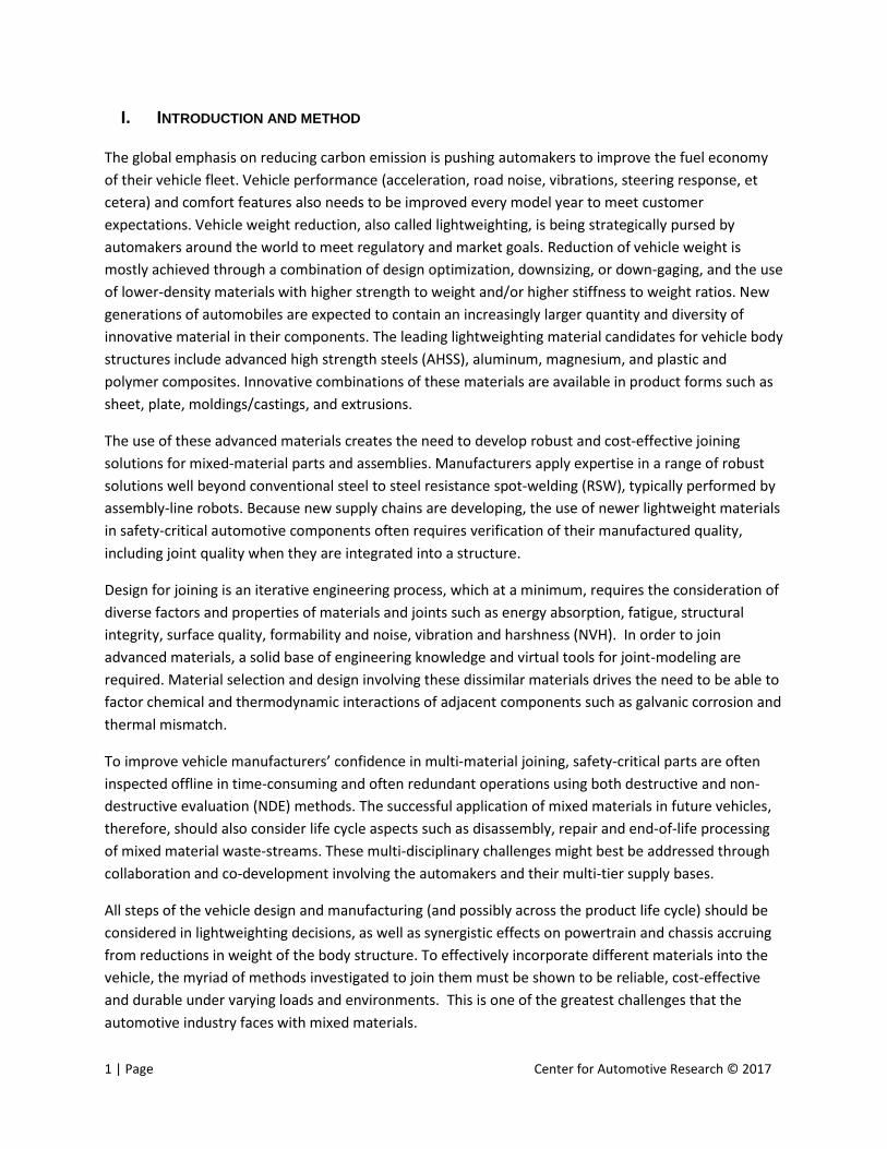
Resistance Spot Welding (RSW) is a commonly used joining method for steels in the auto industry.
Currently, the technology is being developed for dissimilar metals, particularly for welding steel to
aluminum. General Motors claims that it utilized RSW for mixed material applications in 2012 when
producing the 2013 Cadillac CTS-V. This application required joining steel to aluminum on the CTS-V
hood at medium volume production levels. Figure 2 demonstrates the RSW process where sheet metal
is forced between two copper electrodes at the spot of the weld which joins the dissimilar metals. This
process of welding has been extensively tested and documented in engineering literature.
Figure 2: Resistance Spot Welding Process (Source: Vista Industrial Products, Inc.)
Friction Stir Spot Welding
Friction Stir Spot Welding (FSSW) is also a widely-used technology for mixed material joining. It is a solid-
state welding method. This process involves spinning a narrow tool tip positioned perpendicular to the
stacked joining sheets at a speed between 2,000 and 4,500 revolutions per minute (rpm) depending on
the application. When the rotating tool is forced into the sheet, friction heats the material to its plastic
state without fully melting it. This process can be completed in less than two seconds. Figure 3 highlights
the key aspects of an FSSW cycle.

4 | Page Center for Automotive Research © 2017
Figure 3: Friction Stir Spot Welding Process (Source: Coldwater Machine Co.)
Laser Brazing and Laser Welding
Welding creates metal joints by applying concentrated heat at the joint to melt and fuse metals
together. Brazing, on the other hand, involves significantly lower temperatures and does not entail the
melting of base metals. Instead, a filler metal is melted and forced to flow into the joint through
capillary action (Welding usually adds a filler material as well.) Laser brazing is typically used for sealing
applications rather than applications requiring full mechanical strength from the weld. This process
requires that the subject metals be orientated in a fillet weld, or a lap weld configuration which allows
for a small gap between the materials which will be filled with brazing material. Figure 4 highlights this
setup. Brazing material is melted into this gap using a laser. This laser heats the brazing material to its
melting point but remains cool enough not to melt to subject metals. This process provides excellent
corrosion resistance compared to other joining technologies.
Figure 4: Laser Brazing Process (Source: ionix)

5 | Page Center for Automotive Research © 2017
Spin Welding and Vibration Welding
Spin welding and vibration welding are two friction welding processes commonly used for
thermoplastics and polymer composites. The process of spin welding uses heat generated by rotational
friction at the joint line to weld thermoplastic parts with rotationally symmetric joints (see figure 5a).
Linear vibration welding physically moves one of two parts horizontally under pressure, creating heat
through surface friction that melts and welds the parts together (see figure 5b).
Figure 5: a) Spin Welding Process ; b) Vibration Welding Process (source: Branson Ultrasonics)
Infrared (IR) Welding
Infrared welding is another joining process commonly used for plastic components with complex joining
outlines. The surface layer of the component is melted by heat generated through infrared radiation.
The components can then be joined by being pressed together (see figure 6). Infrared heat is transferred
without contact.
Figure 6: Infrared Welding Process (Source: Forward Technology)

6 | Page Center for Automotive Research © 2017
Fasteners
Self-piercing Rivets
Self-piercing rivets (SPR) are a widely-used technology which can be used in applications where
corrosion is not a factor. This fastener works by being forced into a material stack and piercing the top
layer material. The rivet then expands into the bottom layer and forces itself into a die. This process
requires that the bottom layer material is somewhat ductile but in-turn produces a strong mechanical
bond in under three seconds. Figure 7 shows the SPR joining process.
Figure 7: Self-Piercing Rivets Process (Source: Alcoa)
Clinching
Clinching is a common joining technology that does not require consumables or pre-drilled holes. It is
performed in a single step where stacked, ductile materials are pressed into a die with a punch. The
punch forces the materials down and radially out into the die which creates a strong mechanical bond.
This process does not provide corrosion resistance.
Figure 8: Clinching Process (Source: TOX)
7 | Page Center for Automotive Research © 2017
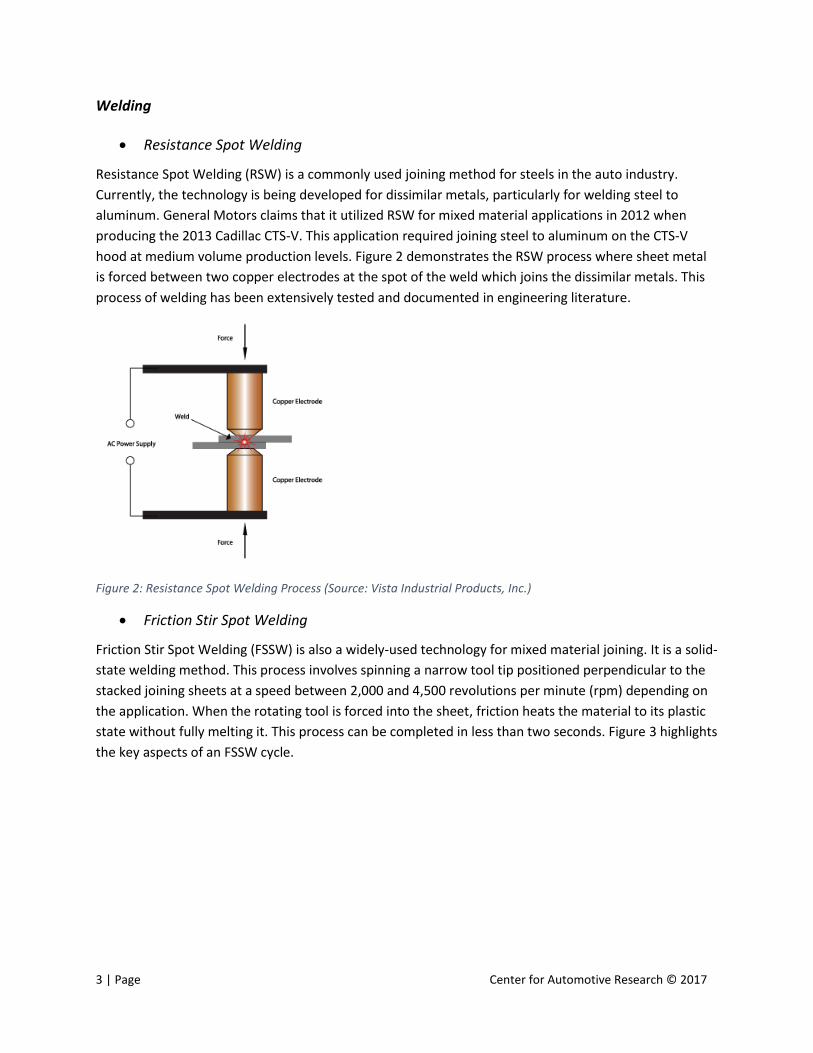
One-sided High Speed Nails
One-sided high speed nails are similar to SPR and clinching in that they do not require pre-drilled holes
but differs in that it only requires one-sided accessibility to the joint. A specially designed tack equipped
with a knurled point is forced into the stacked materials at a very high speed. This displaces the material
and invokes a restoring force on the joint which joins the materials. This process requires that the
subject materials have relatively high stiffness for sufficient restoring force.
Figure 9: One-Sided High Speed Nails Process (Source: Böllhoff)
Adhesive Bonding
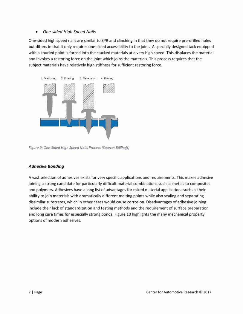
A vast selection of adhesives exists for very specific applications and requirements. This makes adhesive
joining a strong candidate for particularly difficult material combinations such as metals to composites
and polymers. Adhesives have a long list of advantages for mixed material applications such as their
ability to join materials with dramatically different melting points while also sealing and separating
dissimilar substrates, which in other cases would cause corrosion. Disadvantages of adhesive joining
include their lack of standardization and testing methods and the requirement of surface preparation
and long cure times for especially strong bonds. Figure 10 highlights the many mechanical property
options of modern adhesives.
8 | Page Center for Automotive Research © 2017
Figure 10: Property Range of Adhesives (Source: Henkel)
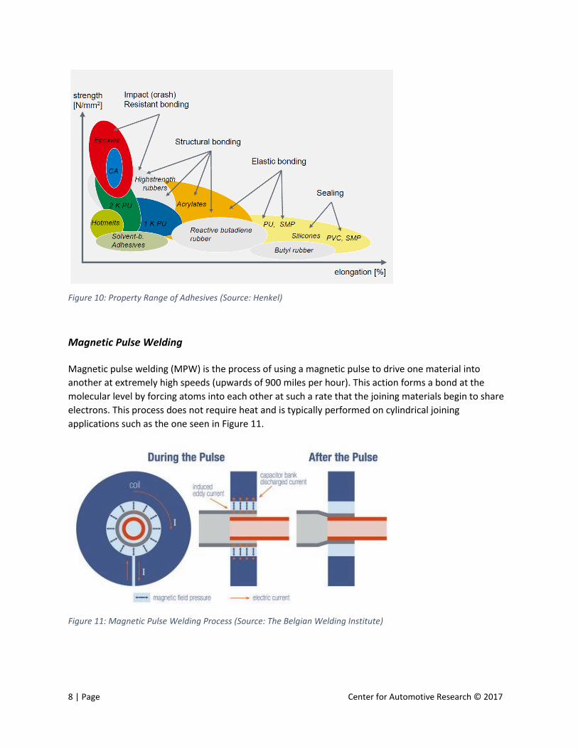
Magnetic Pulse Welding
Magnetic pulse welding (MPW) is the process of using a magnetic pulse to drive one material into
another at extremely high speeds (upwards of 900 miles per hour). This action forms a bond at the
molecular level by forcing atoms into each other at such a rate that the joining materials begin to share
electrons. This process does not require heat and is typically performed on cylindrical joining
applications such as the one seen in Figure 11.
Figure 11: Magnetic Pulse Welding Process (Source: The Belgian Welding Institute)
9 | Page Center for Automotive Research © 2017
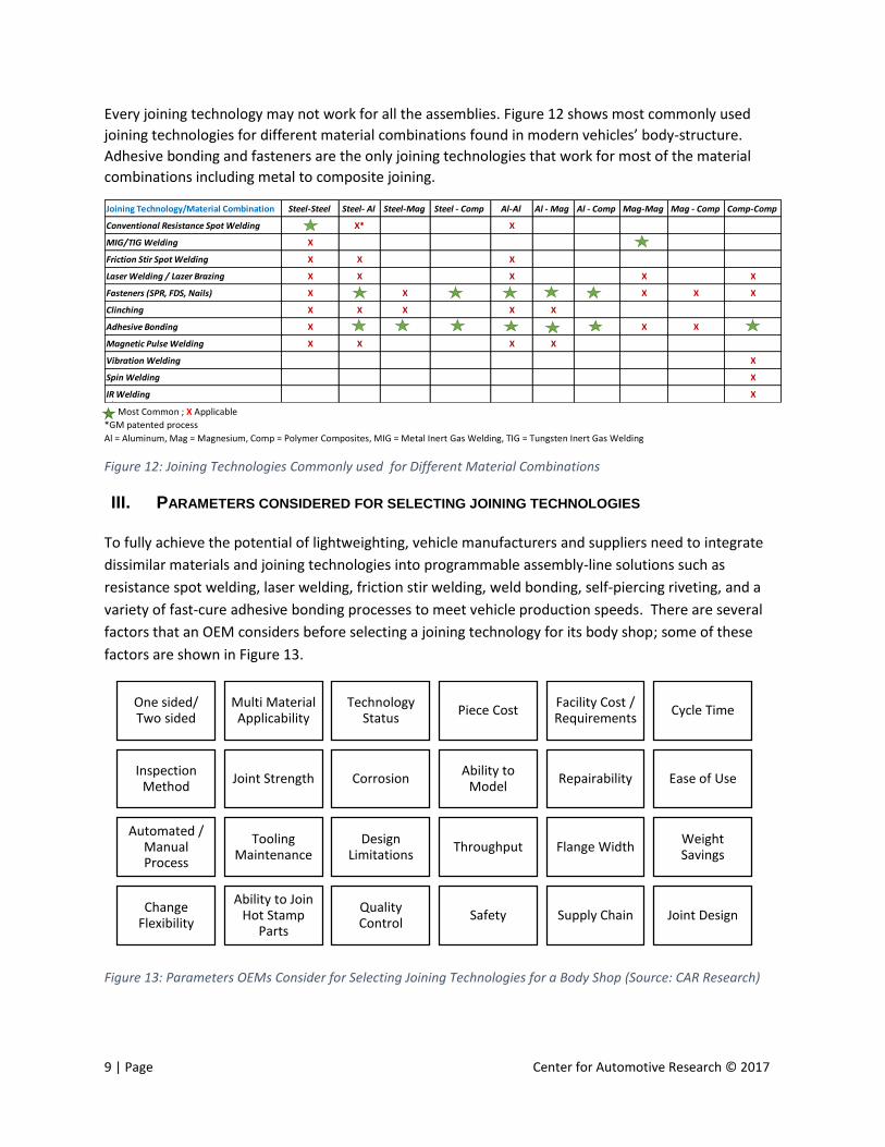
Every joining technology may not work for all the assemblies. Figure 12 shows most commonly used
joining technologies for different material combinations found in modern vehicles’ body-structure.
Adhesive bonding and fasteners are the only joining technologies that work for most of the material
combinations including metal to composite joining.
Most Common ; X Applicable
*GM patented process
Al = Aluminum, Mag = Magnesium, Comp = Polymer Composites, MIG = Metal Inert Gas Welding, TIG = Tungsten Inert Gas Welding
Figure 12: Joining Technologies Commonly used for Different Material Combinations
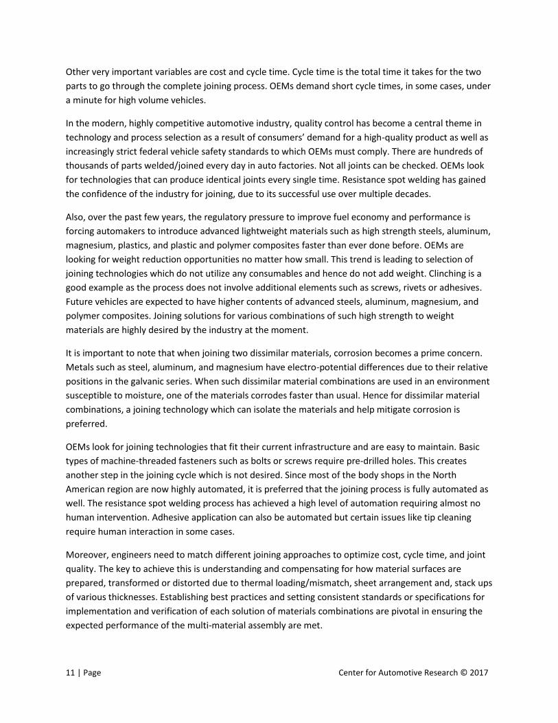
III. PARAMETERS CONSIDERED FOR SELECTING JOINING TECHNOLOGIES
To fully achieve the potential of lightweighting, vehicle manufacturers and suppliers need to integrate
dissimilar materials and joining technologies into programmable assembly-line solutions such as
resistance spot welding, laser welding, friction stir welding, weld bonding, self-piercing riveting, and a
variety of fast-cure adhesive bonding processes to meet vehicle production speeds. There are several
factors that an OEM considers before selecting a joining technology for its body shop; some of these
factors are shown in Figure 13.
Figure 13: Parameters OEMs Consider for Selecting Joining Technologies for a Body Shop (Source: CAR Research)
Joining Technology/Material Combination Steel-Steel Steel- Al Steel-Mag Steel - Comp Al-Al Al - Mag Al - Comp Mag-Mag Mag - Comp Comp-Comp
Conventional Resistance Spot Welding X* X
MIG/TIG Welding X
Friction Stir Spot Welding X X X
Laser Welding / Lazer Brazing X X X X X
Fasteners (SPR, FDS, Nails) X X X X X
Clinching X X X X X
Adhesive Bonding X X X
Magnetic Pulse Welding X X X X
Vibration Welding X
Spin Welding X
IR Welding X
One sided/ Two sided
Multi Material Applicability
Technology Status
Piece CostFacility Cost / Requirements
Cycle Time
Inspection Method
Joint Strength CorrosionAbility to
ModelRepairability Ease of Use
Automated / Manual Process
Tooling Maintenance
Design Limitations
Throughput Flange WidthWeight Savings
Change Flexibility
Ability to Join Hot Stamp
Parts
Quality Control
Safety Supply Chain Joint Design

10 | Page Center for Automotive Research © 2017
A primary consideration is the maturity and applicability of the technology for the material
combinations that need to be joined. Maturity of a technology is a subjective term which depends on
the vehicle program. In broad terms, a mature technology can be used in a mass-produced vehicle
(volume over 100,000 a year), has multiple product applications, and is available from multiple suppliers
with a global base. Even if the technology is mature for high volume production and offers a better
joining solution, it may be difficult to use due to design limitation.
An important consideration while selecting a joining process is the joint design. Figure 14 illustrates a
few basic sheet metal joints. It is important to select the joining process according to the joint design
and vice versa. For example, butt joints provide good lightweighting opportunity but they are not a good
design alternative for adhesive bonding because in order to have good bonding strength, a large surface
overlap area is needed between the materials. Lap joints are better for adhesive bonding; butt joints
can be utilized if laser welding is used.
Figure 14: Basic Sheet Metal Joint Designs (Source: TWI)
Another important consideration is type of access available to the material surfaces. Some technologies
such as resistance spot welding, riveting, clinching, et cetera can work only if there is two sided access
available. If two sided access is not available, technologies such as laser welding, arc welding, one-sided
nails, et cetera should be considered. Designers are demanding one-sided joining solutions to get more
flexibility in part design.
Some joining technologies may also require special surface treatment. Adhesives work best if the
material surface is cleaned prior to application. Recently, adhesive suppliers have launched products
that can work with oily or uncleaned material surfaces. Type of surface coating may also alter the
response of materials to various joining technologies. For example, galvannealed steel is easier to weld
than galvanized steel.
11 | Page Center for Automotive Research © 2017
Other very important variables are cost and cycle time. Cycle time is the total time it takes for the two
parts to go through the complete joining process. OEMs demand short cycle times, in some cases, under
a minute for high volume vehicles.
In the modern, highly competitive automotive industry, quality control has become a central theme in
technology and process selection as a result of consumers’ demand for a high-quality product as well as
increasingly strict federal vehicle safety standards to which OEMs must comply. There are hundreds of
thousands of parts welded/joined every day in auto factories. Not all joints can be checked. OEMs look
for technologies that can produce identical joints every single time. Resistance spot welding has gained
the confidence of the industry for joining, due to its successful use over multiple decades.
Also, over the past few years, the regulatory pressure to improve fuel economy and performance is
forcing automakers to introduce advanced lightweight materials such as high strength steels, aluminum,
magnesium, plastics, and plastic and polymer composites faster than ever done before. OEMs are
looking for weight reduction opportunities no matter how small. This trend is leading to selection of
joining technologies which do not utilize any consumables and hence do not add weight. Clinching is a
good example as the process does not involve additional elements such as screws, rivets or adhesives.
Future vehicles are expected to have higher contents of advanced steels, aluminum, magnesium, and
polymer composites. Joining solutions for various combinations of such high strength to weight
materials are highly desired by the industry at the moment.
It is important to note that when joining two dissimilar materials, corrosion becomes a prime concern.
Metals such as steel, aluminum, and magnesium have electro-potential differences due to their relative
positions in the galvanic series. When such dissimilar material combinations are used in an environment
susceptible to moisture, one of the materials corrodes faster than usual. Hence for dissimilar material
combinations, a joining technology which can isolate the materials and help mitigate corrosion is
preferred.
OEMs look for joining technologies that fit their current infrastructure and are easy to maintain. Basic
types of machine-threaded fasteners such as bolts or screws require pre-drilled holes. This creates
another step in the joining cycle which is not desired. Since most of the body shops in the North
American region are now highly automated, it is preferred that the joining process is fully automated as
well. The resistance spot welding process has achieved a high level of automation requiring almost no
human intervention. Adhesive application can also be automated but certain issues like tip cleaning
require human interaction in some cases.
Moreover, engineers need to match different joining approaches to optimize cost, cycle time, and joint
quality. The key to achieve this is understanding and compensating for how material surfaces are
prepared, transformed or distorted due to thermal loading/mismatch, sheet arrangement and, stack ups
of various thicknesses. Establishing best practices and setting consistent standards or specifications for
implementation and verification of each solution of materials combinations are pivotal in ensuring the
expected performance of the multi-material assembly are met.
12 | Page Center for Automotive Research © 2017
IV. TEST PROCEDURES FOR EVALUATING JOINTS
Testing is important in materials science and engineering to characterize and validate fundamental
properties. The joint between dissimilar materials is commonly accompanied by mismatch in the
mechanical, chemical and physical properties of the parts which have been joined. Mechanical
requirements include the strength, toughness and stiffness of the joint. Chemical requirements include
resistance to corrosion and degradation due to chemical attacks by the environment. Physical
requirement for a joint may be limited to the need to seal an enclosure from the surroundings, and thus
prevent access or egress of gas or liquid. It is important to understand the real-world loading conditions
of the assembly before deciding on the type of test and loading conditions. It is also important to
evaluate, not the joint, but rather a specific joining capability. Hence, many tests are made in order to
evaluate the competence of the welder rather than the weld, while many adhesive joints are prepared
to test the properties of the adhesives rather than the join (especially their shelf life or environmental
sensitivity).1 Testing is especially important for adhesives, where many variables are critical to the
ultimate performance of the bonded joint.2
A joint can fail in multiple ways. Cracking is a common defect that occurs within welded joints. Typically
cracking occurs because of the built-up stress that accumulates when a heated metal is rapidly cooled.
In order to prevent this form of defect the metal should be annealed. Sometimes the issues aren’t so
much the joints themselves, but the surrounding area. Distortion of metal due to heat can cause
undesired stress in the material. Oxidation is also a major issue with welded joints. An oxide can prevent
a good weld from forming. Slag is another troublemaker when it comes to weld joints. This includes
things such as dirt, debris, and oxides that are on the parts when welding occurs.3 Bonded joints can fail
due to failure in adhesive to substrate adhesion, cohesion or both. Figure 15 illustrates modes of failure
in bonded joints.
1 Brandon, W. D. Kaplan, Joining Processes, An Introduction, ISBN: 978-0471964889 2 Messler, Warren Savage, Joining of Advanced Materials, ISBN: 978-0750690089 3 Polymer Solutions, Why do weld joints fail?

13 | Page Center for Automotive Research © 2017
Figure 15: Failure Modes in Bonded Joints (Source: Henkel)
There are two kinds of tests that are often performed for checking the quality of joints:
1. Destructive Test: Some of these tests, such as tensile and bending tests, are destructive, in
that the test specimens are loaded until they fail, so the desired information can be gained.
2. Non-destructive Test (NDT): Other testing methods, such the X-ray and hydrostatic tests, are
nondestructive (NDT). This type of testing is also referred to as NDE or nondestructive
examination and NDI or nondestructive inspection. The goal of these methods is to exam
the welds without causing any damage.
Figure 16 illustrates some common adhesive testing methods. Similar testing methods are utilized for
testing welded and mechanically fastened joints.
Figure 16: Common Adhesive Destructive Testing Methods (Source: www.adhesivetest.com)

14 | Page Center for Automotive Research © 2017
V. MAJOR CHALLENGES WITH MIXED-MATERIAL JOINING TECHNOLOGIES
Materials selection criteria are aimed at satisfying engineering requirements by avoiding failure in both
production and service. The implementation of a joining process must meet the engineering
requirements for the system, both in the course of the joining process and throughout the subsequent
service life of the assembled components. A joint between dissimilar materials is commonly
accompanied by mismatch in the mechanical, physical and chemical properties of the components
which have been joined.4 Described below are the major challenges with mixed-material joining as
identified during the interviews with the subject matter experts at various OEMs and suppliers.
Corrosion
Corrosion is a natural process, which converts a refined metal to a more chemically-stable form, such as
oxide, hydroxide, or sulfide. It is the gradual
destruction of materials (usually metals) by chemical
and/or electrochemical reaction with the
environment. Galvanic corrosion (also called
bimetallic corrosion) is an electrochemical process in
which one metal corrodes preferentially to another
when both metals are in electrical contact, in the
presence of an electrolyte. When a galvanic couple forms, one of the metals in the couple becomes the
anode and corrodes faster than it would by itself, while the other becomes the cathode and corrodes
slower than it would alone. For a galvanic couple, the anode and cathode are determined by their
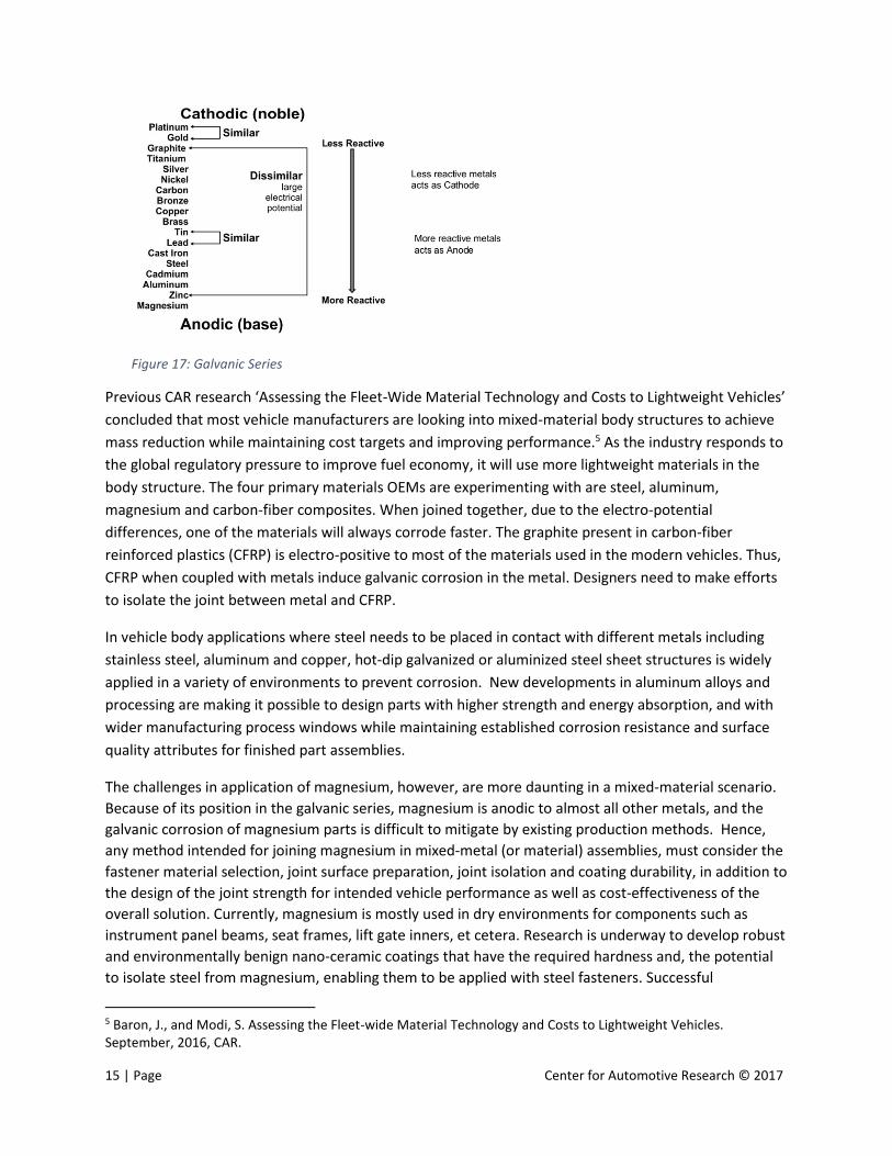
relative position in the galvanic series (see Figure 17). For example, in the case of magnesium joined
with steel, magnesium will act as an anode and will corrode faster. Galvanization (or galvanizing as it is
most commonly called in the industry) is the process of applying a protective zinc coating to steel or iron
to prevent rusting. Zinc serves as a sacrificial anode so that even if the coating is scratched, the exposed
steel will still be protected by the remaining zinc.
4 Brandon, W. D. Kaplan, Joining Processes, An Introduction, ISBN: 978-0471964889
“...major challenge is corrosion as we join
two dissimilar and different electro-
potential metals. Another challenge is how
to make sure quality of joining is robust
every time….” – OEM
15 | Page Center for Automotive Research © 2017
Figure 17: Galvanic Series
Previous CAR research ‘Assessing the Fleet-Wide Material Technology and Costs to Lightweight Vehicles’
concluded that most vehicle manufacturers are looking into mixed-material body structures to achieve
mass reduction while maintaining cost targets and improving performance.5 As the industry responds to
the global regulatory pressure to improve fuel economy, it will use more lightweight materials in the
body structure. The four primary materials OEMs are experimenting with are steel, aluminum,
magnesium and carbon-fiber composites. When joined together, due to the electro-potential
differences, one of the materials will always corrode faster. The graphite present in carbon-fiber
reinforced plastics (CFRP) is electro-positive to most of the materials used in the modern vehicles. Thus,
CFRP when coupled with metals induce galvanic corrosion in the metal. Designers need to make efforts
to isolate the joint between metal and CFRP.
In vehicle body applications where steel needs to be placed in contact with different metals including
stainless steel, aluminum and copper, hot-dip galvanized or aluminized steel sheet structures is widely
applied in a variety of environments to prevent corrosion. New developments in aluminum alloys and
processing are making it possible to design parts with higher strength and energy absorption, and with
wider manufacturing process windows while maintaining established corrosion resistance and surface
quality attributes for finished part assemblies.
The challenges in application of magnesium, however, are more daunting in a mixed-material scenario.
Because of its position in the galvanic series, magnesium is anodic to almost all other metals, and the
galvanic corrosion of magnesium parts is difficult to mitigate by existing production methods. Hence,
any method intended for joining magnesium in mixed-metal (or material) assemblies, must consider the
fastener material selection, joint surface preparation, joint isolation and coating durability, in addition to
the design of the joint strength for intended vehicle performance as well as cost-effectiveness of the
overall solution. Currently, magnesium is mostly used in dry environments for components such as
instrument panel beams, seat frames, lift gate inners, et cetera. Research is underway to develop robust
and environmentally benign nano-ceramic coatings that have the required hardness and, the potential
to isolate steel from magnesium, enabling them to be applied with steel fasteners. Successful
5 Baron, J., and Modi, S. Assessing the Fleet-wide Material Technology and Costs to Lightweight Vehicles. September, 2016, CAR.

16 | Page Center for Automotive Research © 2017
demonstration of such coating technologies could enable the increased use of magnesium alloys to
reduce vehicle weight and improve fuel economy.
Most of the OEM representatives interviewed agreed that understanding corrosion dynamics is very
important. The technology used for joining such multi-materials assemblies should help in mitigating
galvanic corrosion. Adhesives to some extent act as isolators between the two materials but fasteners
are often used with the adhesives which results in contact between the materials if the fastener is not
coated. Anti-corrosion coatings on fasteners, such as zinc, phosphate, polymers, et cetera act as a
barrier to inhibit the contact between chemical compounds or corrosive materials. Overall, galvanic
corrosion is a major challenge to overcome in order to use a mixed-material approach and the “right
material at the right place” philosophy for vehicle weight and performance optimization.
Thermal Expansion
Thermal expansion is the tendency of matter to change in shape, area, and volume in response to a
change in temperature. The coefficient of thermal expansion (CLTE) measures the fractional change in
size per degree change in temperature at a constant pressure. Figure 18 shows how different materials
react to thermal load. The body-in-white needs to go through the paint process which consists of a bake
oven to cure the paint, sealants, and adhesives in the vehicle. The paint bake oven temperatures range
from 180-250 degrees Celsius. The materials in a multi-material body will expand differently due to the
difference in CLTE. This can distort the body-structure if the joints are rigid and do not allow for free
expansion. For example, in a typical large plastic and metal assembly where movement is restricted,
high compressive or tensile stresses can develop. Because in general the plastic part expands more, it
develops a strain-induced compressive stress.6 An equal tensile stress develops in the metal part.
Figure 18: Different Materials Expand Differently Under Thermal Load (Source: CAR Research)
6 There are plastic materials developed which have lower than metal CLTE in one direction
0 0.0001 0.0002 0.0003 0.0004 0.0005 0.0006 0.0007 0.0008
ABS - glass fiber reinforced
Magnesium
Aluminum
Steel
Wood, parallel to grain
Delta L (m)
Initial Length = 1 meterTemperature Difference = 25 degree Celsius
17 | Page Center for Automotive Research © 2017
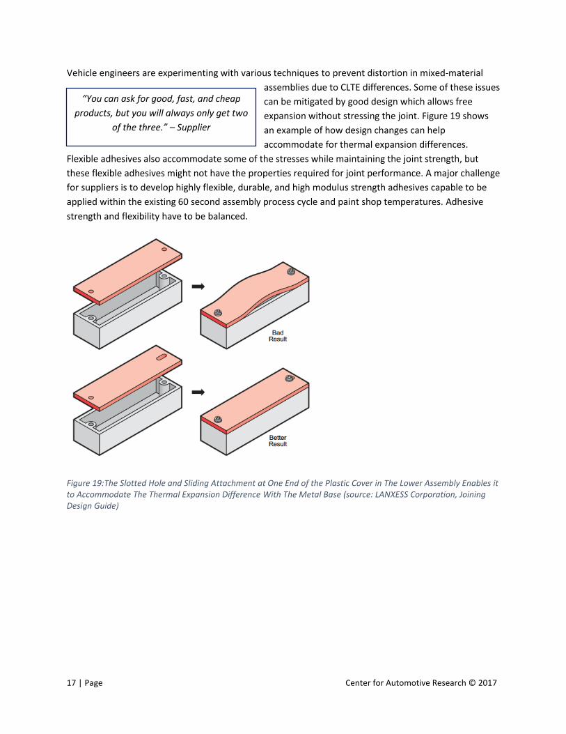
Vehicle engineers are experimenting with various techniques to prevent distortion in mixed-material
assemblies due to CLTE differences. Some of these issues
can be mitigated by good design which allows free
expansion without stressing the joint. Figure 19 shows
an example of how design changes can help
accommodate for thermal expansion differences.
Flexible adhesives also accommodate some of the stresses while maintaining the joint strength, but
these flexible adhesives might not have the properties required for joint performance. A major challenge
for suppliers is to develop highly flexible, durable, and high modulus strength adhesives capable to be
applied within the existing 60 second assembly process cycle and paint shop temperatures. Adhesive
strength and flexibility have to be balanced.
Figure 19:The Slotted Hole and Sliding Attachment at One End of the Plastic Cover in The Lower Assembly Enables it to Accommodate The Thermal Expansion Difference With The Metal Base (source: LANXESS Corporation, Joining Design Guide)
“You can ask for good, fast, and cheap
products, but you will always only get two
of the three.” – Supplier
18 | Page Center for Automotive Research © 2017
Cycle Time
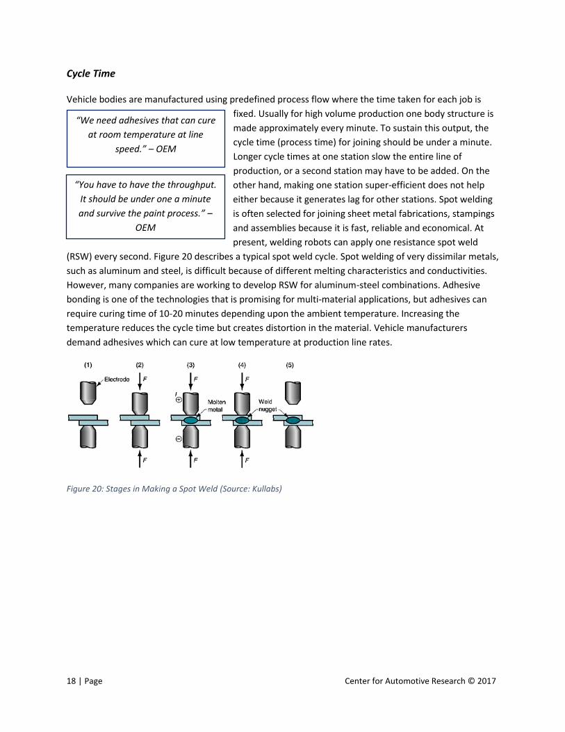
Vehicle bodies are manufactured using predefined process flow where the time taken for each job is
fixed. Usually for high volume production one body structure is
made approximately every minute. To sustain this output, the
cycle time (process time) for joining should be under a minute.
Longer cycle times at one station slow the entire line of
production, or a second station may have to be added. On the
other hand, making one station super-efficient does not help
either because it generates lag for other stations. Spot welding
is often selected for joining sheet metal fabrications, stampings
and assemblies because it is fast, reliable and economical. At
present, welding robots can apply one resistance spot weld
(RSW) every second. Figure 20 describes a typical spot weld cycle. Spot welding of very dissimilar metals,
such as aluminum and steel, is difficult because of different melting characteristics and conductivities.
However, many companies are working to develop RSW for aluminum-steel combinations. Adhesive
bonding is one of the technologies that is promising for multi-material applications, but adhesives can
require curing time of 10-20 minutes depending upon the ambient temperature. Increasing the
temperature reduces the cycle time but creates distortion in the material. Vehicle manufacturers
demand adhesives which can cure at low temperature at production line rates.
Figure 20: Stages in Making a Spot Weld (Source: Kullabs)
“We need adhesives that can cure
at room temperature at line
speed.” – OEM
“You have to have the throughput.
It should be under one a minute
and survive the paint process.” –
OEM
19 | Page Center for Automotive Research © 2017
Standardization
A single car has about 30,000 parts, making it a very complex machine. Product designers strive to
simplify design and standardize components and
manufacturing technologies as much as possible. The recent
trend in the automotive industry is to reduce the number of
platforms and promote more part sharing between vehicles
to share engineering cost and reduce complexity. Among the
various joining technologies, resistance spot welding is very
standardized. The major OEMs follow the national or
international standards for RSW. Also, spot welding works for
almost any type of steel combination with minor adjustments, which is a major advantage. On the other
hand, adhesives and fasteners are the least standardized. Fasteners are custom made for the product
application which increases engineering cost and complexity. Adhesives, too, are engineered as per the
application and there are no available national or international standards. Adhesive suppliers do not
want to commoditize their product because adhesive chemistry can be altered to better suit the
application. OEMs however are not in favor of specialized products because it adds complexity in the
body-shop. A product which can be purchased as a commodity from multiple suppliers is the priority as
it reduces cost, distributes risk of supplier production failure and, simplifies the manufacturing process.
OEMs also need the material and manufacturing technology to be available in all markets. At the
moment, some of the material grades and joining technologies which are available in Europe are not
available in North America. Also, the crash and emissions testing standards are different. Harmonization
of standards will accelerate the pace of technology introduction and will help the industry in general.
Various performance tests need to be executed for qualifying the technology to be used in production.
Most of the test procedures are decided
by the OEMs. There are no standardized
set of test procedures followed by the
industry. This makes the qualification
process time consuming and expensive.
Also, the software companies are unable
to create standard simulation packages
for joining analysis. Another issue with adhesives and fasteners is inventory management. The shelf life
of adhesives is only a few months in a closed barrel. Once the barrel is open, it needs to be used quickly.
“There is a need to come up with a
robust process like welding for mixed
materials. We need a dumb process
that works for everything.” – OEM
“We invest time with design and manufacturing
department at the OEMs. Then we need to deal with
purchasing who always demands commodity products.
Adhesives are highly engineered products; they will lose
their performance if commoditized.” – Supplier

20 | Page Center for Automotive Research © 2017
Nondestructive Evaluation and Computer Analytical Methods
While destructive physical testing is the best way to test joint performance, it is not economical for a
mass-produced vehicle. The automotive industry has been
joining steels with steels and to some extent aluminum with
aluminum over the last 100 years by using either welding or
rivets. Nondestructive Evaluation (NDE) techniques such as
ultrasonic, eddy current, X-ray, radiography, etc. have been
developed to test welds. Computer-aided engineering (CAE)
analysis tools are capable of predicting performance of welded
assemblies. However, the results are not always accurate enough
to match real world performance. Vehicle designers often add extra welds for safety. Accurate
prediction of real world performance, along with good process control is needed to eliminate
unnecessary welds and reduce the safety factor.
The growing use of carbon and glass-fiber reinforced polymer composites poses significant challenges
when these structures have to be
attached to existing steel or
aluminum/metallic vehicle sub-
structures, such as frame rails,
chassis, seating and roof structures.
Composites may be joined to metals with adhesives, which, in the manufacturing environment, are
vulnerable to substrate contamination such as lubrication oil. The curing process, if not tightly
controlled, can cause a number of process and downstream quality problems. Excess adhesives are
known to contaminate the painting process if not applied or cured properly. Substrates intended for
adhesive applications may have to be conditioned, driving up cost and process complexity. Joints with
adhesives may be supplemented with fasteners or weld-bonded to overcome process variation or to
increase peel strength. Due to these complexities, the tools and technologies for modeling of structural
adhesive joints are not considered implementation-ready, when compared with tools for metal-to-metal
joining. This forces the OEMs to perform destructive testing and to do extensive in-process control
which is a roadblock for new joining technologies.
“Math models are important
because if you don’t have
predictive analysis, nobody is
going to trust it before it is being
used in the production for at least
five years.” – Supplier
“If the failure happens in the field but there are no
mathematical models that can predict failure, you feel lucky,
but you gain no confidence in the technology.” – Supplier

21 | Page Center for Automotive Research © 2017
Intellectual Property
Most of the OEMs are putting forth efforts to solve their mixed-material joining problems. European
automakers in general are ahead of the curve in joining
technology research and implementation. OEMs who have
not used mixed-material body applications in the past and
do not have big R&D centers struggle to maintain their
competitiveness. Since the internal company research is
often protected by intellectual property rights, other
companies cannot use it without paying a large premium. Likewise, individual universities and
companies are also working internally to develop nondestructive evaluation methods. There is no
consortium of companies in the North America region to study mixed-material bonding at a
precompetitive level and publish results in a public domain format. There needs to be an industry-driven
effort (primarily driven by the OEMs) to advance technologies for mixed-material joining.
Legacy Mindset
OEMs are very risk averse by nature. New technologies pose several risks such as part failure, supply-
chain delays, end-of-life recycling issues, high upfront cost, et
cetera. The engineers want to take minimum risk because a
small error can cost billions of dollars in vehicle recalls and
legal fees. If a process or technology has been used for several
decades and is proven in the field, the task of replacing it
seems daunting. Even when the new joining technologies like
adhesives are ready for mass production and meet
performance and cost requirements, the OEMs are reluctant
because lab testing cannot simulate all the conditions in the field. This legacy mindset is one of the
biggest barriers to entry for any new technologies in the body shop. CAR’s previous research, ‘Material
Qualification in the Automotive Industry’ identified leadership approval as one of the major barriers to
entry for new materials.7 Regulatory pressure to improve fuel economy is pushing automakers to
implement new technologies at a faster rate. OEMs are introducing these material and manufacturing
technologies into premium low volume vehicles or in platforms which are not sold globally. For example,
BMW used carbon fiber as the primary material for the i3 and used adhesives as the primary joining
technology. BMW developed technology knowledge through implementation in the low volume vehicles
such as i3 and i8 and then used the learnings in the 7-series which is produced in relatively higher
volumes. Similarly, GM used 13 different materials and numerous joining technologies in the Cadillac
CT6 which is a premium, low volume vehicle. Technology demonstrations in precompetitive
collaborative research projects such as the Multi-Material Lightweight Vehicle (MMLV) (a concept
7 Modi, Shashank. Material Qualification in the Automotive Industry. Center for Automotive Research, Ann Arbor, MI. November 2016.
“Fighting the old process is a major
challenge.” – Supplier
“Mixed-material bonding research is
done at OEMs internal R&D centers.
Hence the research resides at one OEM
and nobody else can use it.” – Supplier
“If you are doing the same thing for
20 years, you are most probably
doing it wrong.” – Supplier

22 | Page Center for Automotive Research © 2017
vehicle designed by Ford and Magna under a project funded by the U.S. Department of Energy’s Vehicle
Technologies Office) can help develop confidence in new material and manufacturing technologies.
Repair
Miles driven in the United States reached 3.148 trillion miles by the end of 2015, beating the previous
record of 3.003 trillion miles in 2007. For a sense of
scale, 3.148 trillion miles is roughly the same distance
as 337 round trips from Earth to Pluto.8 The increase in
miles driven carries an unfortunate component.
Accident frequency is at its highest level in a decade,
rising steeply in 2014 and 2015 in strong correlation with the spike in miles driven.9 Figure 21 shows that
the frequency of vehicle collision damage claims rise with vehicle miles driven and has been
continuously increasing since 2007. Thus, easy reparability is an important consideration while selecting
materials and joining technologies. A difficult-to-repair vehicle will have increased insurance costs and
this in turn may affect sales. The industry has learned how to repair steels joined with spot welding over
a period of decades. New materials such as polymer composites, aluminum, and magnesium assembled
together with the help of adhesives and fasteners pose a significant challenge for the repair personnel.
Use of non-standard fasteners require custom tooling in the repair shops, which is an expensive
investment for small shops. Recently, the industry has witnessed some breakthroughs in reversible
bonding, enabling the auto repair industry, as well as advancements in weld tip design for direct
resistance spot welding of aluminum and steel.
Some of the OEMs with composite intensive vehicles have flagship dealerships with trained staff.
Customers are expected to remain loyal with the company’s flagship dealerships for service and repair
of their composite body-structure vehicles. OEMs also provide special training to dealership staff for
aluminum body panel repairs.
8 U.S. Department of Transportation’s (USDOT) Federal Highway Administration (FHWA) 9 Verisk Analytics, Inc.
“The repair processes for new technologies
need to work at dealership and
independent repair facilities.” – OEM

23 | Page Center for Automotive Research © 2017
Figure 21: Frequency and Severity of Collision Physical Damage Claims from 2007-2015
Stranded Capital
The automotive industry is very capital intensive. Large investments are required to buy equipment and
space for production. The body shop and
paint shop absorb much of the money
spent. The decision regarding which
technologies to be used in future vehicle
programs are made several years in
advance of start of production. Once the
component and assembly plants are up
and running, it becomes very difficult to change the manufacturing process or use a new technology
because of the prior investments which run in billions of dollars. In North America, the body shops
usually go through two changes in vehicle platforms before being fully amortized. This period can range
from 12-15 years. OEMs are willing to put new equipment in the plant after the amortization cycle is
completed to get the most value out of their investments. Due to the risk of stranded capital, that is,
capital investment that becomes obsolete before full pay-back, OEMs are reluctant to implement new
technologies into vehicles even if they are production ready and will improve vehicle performance.
“We are not building new plants very often. New body
shops are an expensive investment. OEMs do not want to
do that. If the platform is competitive then they will
continue with it. Thus, integration of new technologies in
existing plants is difficult.” – OEM
24 | Page Center for Automotive Research © 2017
Talent Gap
University education does not always line up with the skills needed for the real world, especially at the
undergraduate level. Welding has a well-
established curriculum in most of the
universities and community colleges, but it is
very difficult to hire a joining (adhesives,
fasteners etc.) engineer directly out of a
university. There is also a shortage of factory workers. Young students are not getting attracted towards
manufacturing due to its “rust belt” image. Parents are not encouraging their kids to work for the
automotive industry because they are fearful of another recession. CAR past research showed that one-
third of motor vehicle & parts employees currently are or will soon be eligible to retire. Moreover,
private and public spending on job training is not growing (hours of training per year remain flat). With
the current scenario, the industry will face a dire shortage of talent in the near future. It is essential to
change the image of the automotive industry and understand the needs and aspirations of young
professionals. Young professionals today demand flexible working hours, clean environments, non-
monotonous work, and competitive pay. Marketing on social media, factory tours, sponsored
apprenticeships and internships programs, career fairs, et cetera may inspire young students to consider
careers in automotive. One company or organization cannot possible solve the talent crisis. It must be a
collaborative effort between the automotive OEMs, suppliers, NGOs, and the government.
VI. FUTURE POTENTIAL WORK AND NEXT STEPS
Working through the multiple interviews of companies and meetings of engineers uncovered a list of
items needing additional study. The list of issues continues to grow as new solutions are developed and
tested. There are five of these issues listed here to be expanded on and reviewed as potential future
work that may be undertaken by the Coalition for Automotive Lightweighting Materials (CALM). Every
item noted here represents some level of value for the CALM companies and their customers. The list
includes:
1. Determine which assembly plants are likely to refresh their body and / or paint shops next
2. Align fasteners with recommended adhesives
3. Publish the recommended testing procedures to use with particular material mixes
4. Outline the next steps for the existing CALM mixed-material lightweight door project10, to assign
the joining techniques, locations, analysis, adhesives, fasteners and prototypes for the particular
solutions studied
5. Determine and document alternative geometries to isolate, absorb or address thermal
expansion
10 Stevens, M., Modi, S., & Chess, M., Mixed Material Solutions: Alternative Materials for Door Assemblies, CAR, August, 2016
“For the first time, we were able to hire a joining
expert directly from a university. Most of the
students coming out of colleges are just taught
welding. This creates a talent gap.” – Supplier
25 | Page Center for Automotive Research © 2017
All these ideas together help define the ultimate goal, to seek out alternatives of similar or less cost with
any weight savings, regardless of the material used in the assembly.
Assembly Plant Change-over Forecast
It is apparent that there is a sweet spot in timing the recommendations for introducing new equipment,
tooling and materials into an assembly operation. That specific point occurs as the plant is to go
through its normal, planned upgrades, as it readies for change-over to manufacturing new model
vehicles. This information is well known inside OEMs, and is part of their internal, regular program
planning cadence. This information is almost never shared or published, as it represents key portions of
a company’s investment plans. Those specific dates typically could move several times over the 10- or
12- year plans for most body shop changes, and going public at an early stage would prove to be a
distraction for the OEM as many project, location and model decisions change for a myriad of reasons.
The lack of this information drives the supplier community through unproductive pitches of ideas when
there is little opportunity for application. For example, Ford recently completed the second round of
product launches inside the F-150 plants as it introduced the Super Duty version. These plants now are
on their second year of full production for the F series, and have yet to complete one model life cycle.
Since most body shops use their installed infrastructure (robots mostly) for at least two product cycles
(turns), it would be of little value to pitch new ideas to add new equipment or alternatives for these
locations.
On the other hand, a plant that has successfully completed a full cycle of production on its original
models launched when the body shop was first installed, and which is now at least half way through the
four, five or six-year life planned for the most recent models launched, is ripe for considering new ideas,
alternative equipment or layouts, and even new materials. As a plant enters its second half of the
timing for the second turn, alternatives for the next major change are being analyzed and debated by
the OEM. This is an important time for the supplier community to present their new ideas, as the OEM
needs to incorporate these concepts before it locks in on a new plant layout supporting new or changed
processes and materials. To support this concept, the CAR research team recommends:
Opportunity 1: Develop a database of all assembly plants in North America, noting their current
products, date of launch, and expected timeframe for the next major change-over. This will provide a
sequenced list of plants to the suppliers to consider for proposing new ideas and concepts.

26 | Page Center for Automotive Research © 2017
Align Fasteners with Recommended Adhesives
Throughout the course of meetings and interviews with OEMs and suppliers, a common theme
regarding fasteners was uncovered. While it was apparent that there will continue to be a demand for
fasteners specified by OEMs, fasteners will be used in tandem with adhesives to enable multi-material
solutions. It is also apparent there is no recommended listing of fasteners and adhesives published
together, and the industry relies on the OEM to specify the required adhesive. The background of the
engineers releasing the sub-assembly at the OEM are more directed to vehicle engineering, and less
typically on the chemical engineering. It is of interest that the vehicle engineers may be the least able to
determine the recommended link between specific fasteners and adhesives, without relying on the
suppliers. This leads to the second of the five listed potential tasks to consider for CALM.
Publish Recommended Testing Procedures
Another discovery along the journey of many interviews was the wide variety of methods being applied
across industry to validate the joints derived from combinations of fasteners and adhesives. Time and
again during the meetings with various OEMs and suppliers, this lack of an accepted standard and / or
method was noted as one of the leading roadblocks to multi-material solutions.
When an OEM specifies a steel solution, it relies on time-tested and proven analytic testing backed up
by industry standard validation methods. For example, if a sub-assembly specified a typical steel to steel
joint, a standard finite element analysis would be applied to determine the number and location of
welds, and the resultant strength and durability of the joint to be expected. This would be backed up
with a standard monitoring process of amperage in the welding process, and a standard pull and peel
test in physical validation. These standards would be expected by any OEM and/or supplier, and are
generic to the industry.
During the interviewing process, it was reported that the industry lacked such a standard process for the
use of adhesives or combinations of adhesives and fasteners. In its place, the OEM or supplier typically
measures the amount of adhesive applied, and then again after assembly to verify the process was
correctly followed. While this validates a correct procedure was in place, it has no means to determine
if the adhesive actually bonded.
There were some discussions indicating on-going research at the university level to provide an analytic
approach to the design and simulated testing of bonded joints, but these were viewed as incomplete
Opportunity 2: Publish a listing of cross-referenced fasteners and adhesives recommended by industry
experts identifying the recommended combinations when dealing with multi-material solutions.
Opportunity 3: Publish an industry-wide standard procedure for testing the bonding of various
materials, and make this publication available to all universities conducting valuable research in this
effort.
27 | Page Center for Automotive Research © 2017
and certainly not accepted as an industry standard at this point. This leads to the third proposed
potential work for CALM.
Next Steps for CALM Door Project
Throughout the process of meetings and interviews there was much discussion about the dozen
potential material combinations referenced in the original CALM mixed-material lightweight door
project. The resulting presentation and white paper regarding door assemblies provided 12 alternatives
of material combinations each resulting in a different total door weight. Each alternative represented a
different targeted niche for application, with its own optimum volume and specific cost per pound saved
as compared to the original mild steel design.
Several times during the interview process it was recommended to add these joining process
recommendations to the existing CALM Door Study; this becomes the fourth of five proposed work
efforts for the CALM coalition.
Recommended Geometries
At nearly every site visited, it was mentioned the OEMs or suppliers had issues with thermal expansion
when applying solutions of mixed materials. This is due to the difference in expansion and contraction
rates, as each material responds to temperature changes in its own unique manner. For example, an
assembly of steel and aluminum has to accommodate for aluminum expanding at a faster rate than the
steel when the vehicle goes through the heat of the electro-coating and paint bake oven processes. This
also brings forth another issue, since as the assembly cools, the aluminum will cool faster than the steel.
As the interview process uncovered the issues, it also exposed the various methods deployed to remedy
thermal growth at various rates. It became clear each OEM and supplier would work on altering the
product geometry in order to address thermal expansion. A simplistic concept would be the addition of
a bead in the design, to act as an isolator of the joint. What this feature looked like, how deep, how
wide, where it started and stopped, etc., was figured out each time. There were examples discussed
Opportunity 4: Document the variety of joining methods most appropriate for any of the 12 mixed-
material door assembly solutions presented in the previous CALM study.
Opportunity 5: Study, sort and document past remedies for thermal expansion differences in mixed-
material assemblies. These would be published in a set of design guidelines for the overall industry,
showing recommended geometry and material for the joints, including the recommended adhesives
most appropriate for the particular application. This could be approached like the design-for-
manufacturing guidelines typical in the automotive industry, where the guidelines are generic, and
continuously updated.
28 | Page Center for Automotive Research © 2017
where this was not discovered prior to tooling, which led to expensive rework just prior to launch
activities. Therefore, the fifth recommendation of future work for the CALM coalition addresses this
issue.
VII. SUMMARY AND THE WAY FORWARD
Regulatory pressure and customer requirements are pushing new lightweight materials into the vehicle
body structure. The leading lightweighting material candidates for vehicle body structures include
advanced high strength steels (AHSS), aluminum, magnesium, plastics and polymer composites. Vehicle
designers are looking forward to apply the right material at the right place to achieve lightweight body-
structures which are also optimized for better performance. Advancements in manufacturing
technologies such as hot forming, resin transfer molding, 3D printing, etc. are making it possible to
produce lightweight parts in high volume.
The auto industry faces a major challenge with joining dissimilar materials. A large selection of mixed
material joining technologies are already available and have been proven effective for a variety of
applications. The industry has witnessed recent breakthroughs in reversible bonding which will enable
easy repair, as well as advancements in weld tip design for direct resistance spot welding of aluminum
and steel. However, many promising technologies may not be ready for mass production and require
further research and development efforts. The current major challenges include galvanic corrosion,
thermal expansion differences in materials, longer production cycle times, non-availability of non-
destructive testing methods for joint evaluation, and the risk averse nature of the OEMs. The
automakers demand availability of technology across the globe. Also, the repair processes for new
technologies need to work at dealership and independent repair facilities.
As the overall industry continues to push forward with lightweight mixed-material solutions, the Center
for Automotive Research researchers expect to see additional breakthrough technologies, especially
those related to: analytical nondestructive testing procedures, standardization of material, adhesives
and fasteners across world markets, and flexible adhesives with lower cure temperature.
Joining is clearly a critical enabler to mixed material vehicles. This whitepaper investigates some of the
popular methods for mixed material joining, and identifies gaps and challenges in their implementation
for a mass-produced vehicle. This report highlights challenges and opportunities in joining of dissimilar
materials and outlines critical OEM requirements for mixed material structural joining and process
capabilities and related concerns. This paper serves as a reference document to help clarify and
recommend nomenclature, joint design strategies, joining methods, metrics, joint-isolation, testing,
repair, and more to advance meaningful discussions and to identify opportunities for further research
collaboration, and seeks to help accelerate knowledge transfer and access to additional lightweighting
solutions.

29 | Page Center for Automotive Research © 2017
CAR and the Coalition for Automotive Lightweight Materials (CALM), a consortium of 40 major
automotive suppliers, stand ready to take on the projects needed by the auto industry to attain these
goals.
Top Related