


Languages
Pages
Legal


7/27/2019 Mitchell Pad Bearing Experimental Report
http://slidepdf.com/reader/full/mitchell-pad-bearing-experimental-report 1/12
MITCHELL PAD BEARING LABORATORY 1
Q u e e n s l a n d U n i v e r s i t y o f T e c h n o l o g y
Mitchell Pad Bearing Laboratory
ENB434 Tribology
Aaron Palm 07565887
7/27/2019 Mitchell Pad Bearing Experimental Report
http://slidepdf.com/reader/full/mitchell-pad-bearing-experimental-report 2/12
MITCHELL PAD BEARING LABORATORY 2
Table of Contents
INTRODUCTION 3
MATERIALS AND METHODS 3
RESULTS 4
DISCUSSION 8
CONCLUSION 9
APPENDICES 10
Figure 1 ______________________________________________________________________________________________________________ 3 Figure 2 ______________________________________________________________________________________________________________ 4 Figure 3 ______________________________________________________________________________________________________________ 5 Figure 4 ______________________________________________________________________________________________________________ 6 Figure 5 ______________________________________________________________________________________________________________ 6 Figure 6 ______________________________________________________________________________________________________________ 7 Figure 7 ______________________________________________________________________________________________________________ 7
Table 1 .......................................................................................................................................................................................................... 5 Table 2 .......................................................................................................................................................................................................... 5
7/27/2019 Mitchell Pad Bearing Experimental Report
http://slidepdf.com/reader/full/mitchell-pad-bearing-experimental-report 3/12
MITCHELL PAD BEARING LABORATORY 3
Introduction
Viscosity is commonly regarded as the most important rheological property of a fluid
lubricant. The viscosity is a measure of a fluids resistance to the shearing motion induced in
the fluid by an external force. This becomes increasingly significant when the lubricant is
used to separate two surfaces of adequate geometries that are under load, moving at arelative velocity to one another. Such a phenomenon is known as hydrodynamic
lubrication, where the two surfaces are know as a runner and bearing. The runner is wetted
by the fluid lubricant and moves at a relative velocity to the bearing. For a linear pad
bearing, the fluid is squeezed between the runner and bearing where the bearing is inclined
at a specific angle to generate sufficient fluid pressures to support the load that forces the
two surfaces together. In conjunction with this, the relative velocity between the two
surfaces must also be of a sufficient magnitude to generate adequate hydrodynamic fluid
thicknesses. This experiment will evaluate the effects on the fluid pressure when the
velocity of the runner, inclination or wedge angle and the trailing edge film thickness are
varied in separate instances.
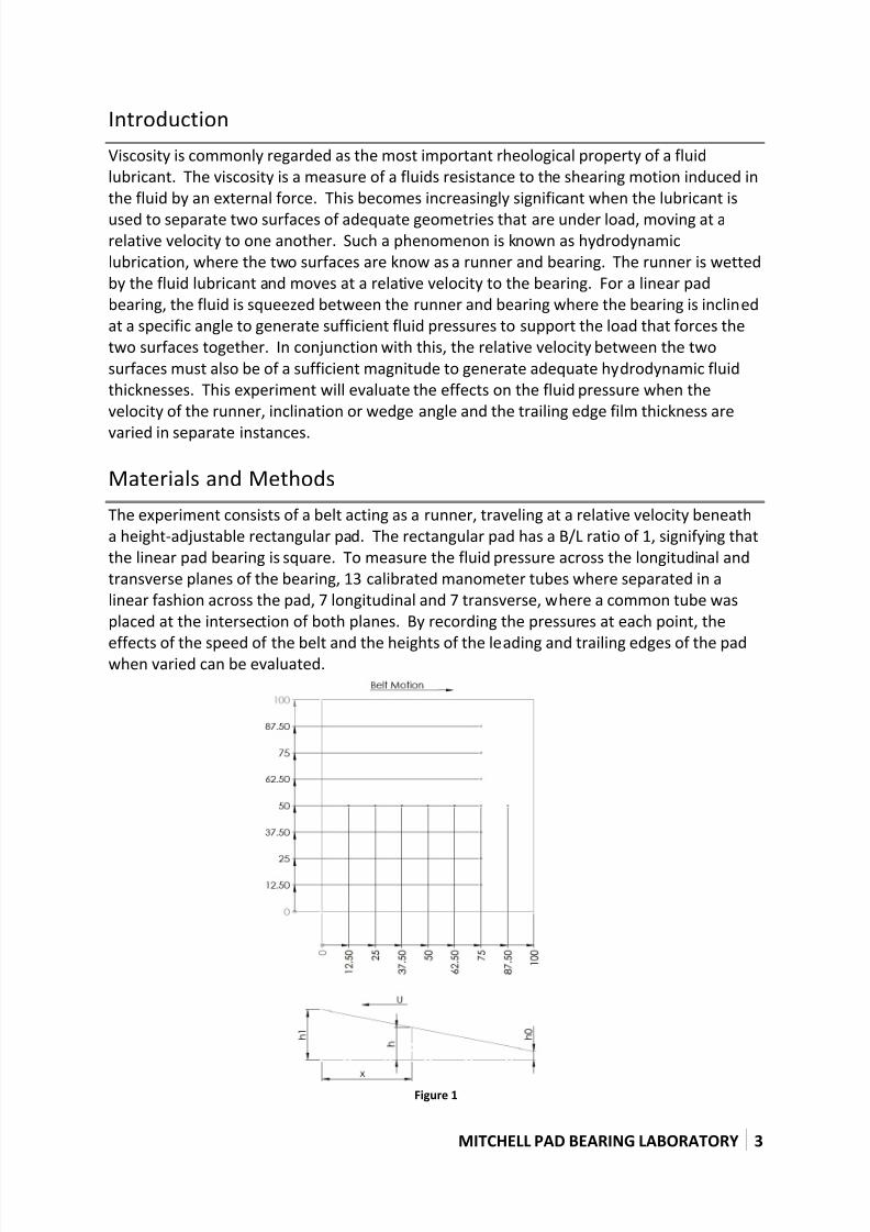
Materials and Methods
The experiment consists of a belt acting as a runner, traveling at a relative velocity beneath
a height-adjustable rectangular pad. The rectangular pad has a B/L ratio of 1, signifying that
the linear pad bearing is square. To measure the fluid pressure across the longitudinal and
transverse planes of the bearing, 13 calibrated manometer tubes where separated in a
linear fashion across the pad, 7 longitudinal and 7 transverse, where a common tube was
placed at the intersection of both planes. By recording the pressures at each point, the
effects of the speed of the belt and the heights of the leading and trailing edges of the padwhen varied can be evaluated.
Figure 1
7/27/2019 Mitchell Pad Bearing Experimental Report
http://slidepdf.com/reader/full/mitchell-pad-bearing-experimental-report 4/12
MITCHELL PAD BEARING LABORATORY 4
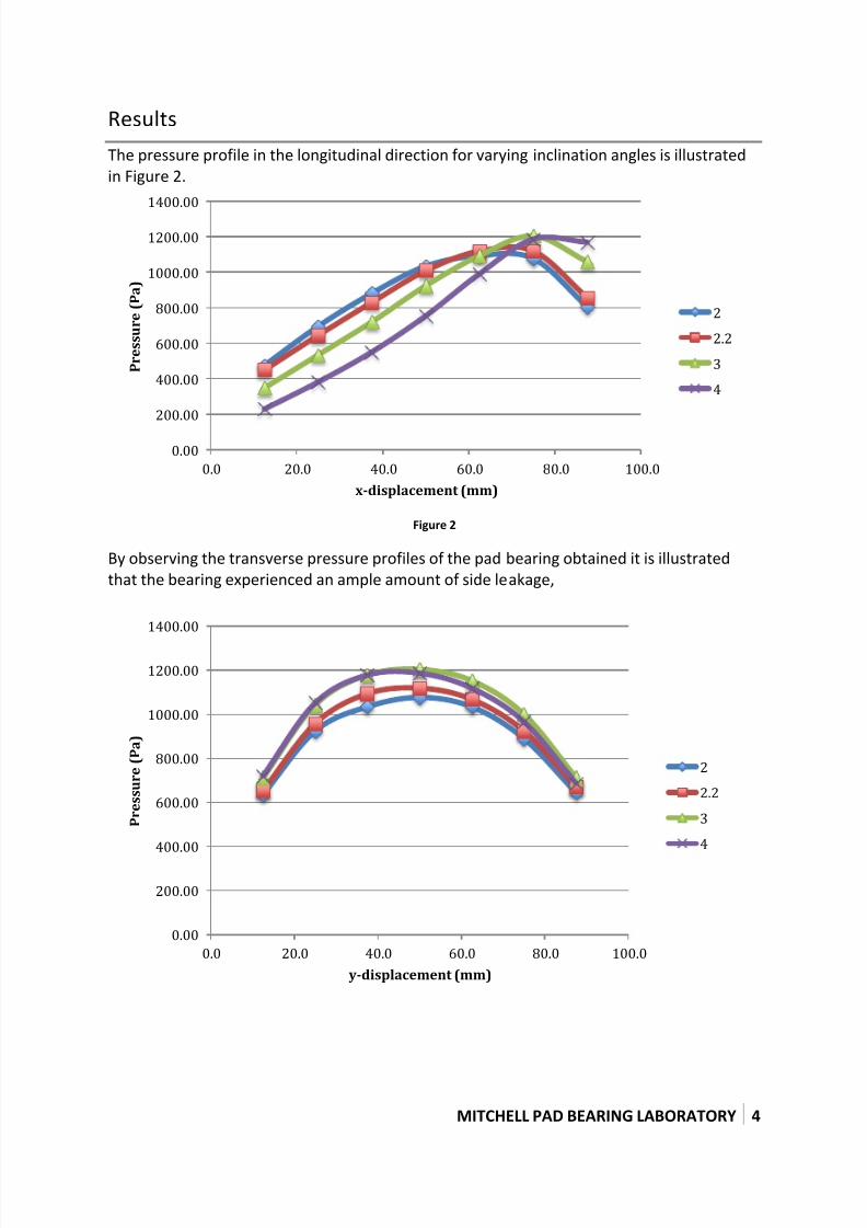
Results
The pressure profile in the longitudinal direction for varying inclination angles is illustrated
in Figure 2.
Figure 2
By observing the transverse pressure profiles of the pad bearing obtained it is illustrated
that the bearing experienced an ample amount of side leakage,
0.00
200.00
400.00
600.00
800.00
1000.00
1200.00
1400.00
0.0 20.0 40.0 60.0 80.0 100.0
P r e s s u r e ( P a )
x-displacement (mm)
2
2.2
3
4
0.00
200.00
400.00
600.00
800.00
1000.00
1200.00
1400.00
0.0 20.0 40.0 60.0 80.0 100.0
P r e s s u r e ( P a )
y-displacement (mm)
2
2.2
3
4
7/27/2019 Mitchell Pad Bearing Experimental Report
http://slidepdf.com/reader/full/mitchell-pad-bearing-experimental-report 5/12
MITCHELL PAD BEARING LABORATORY 5
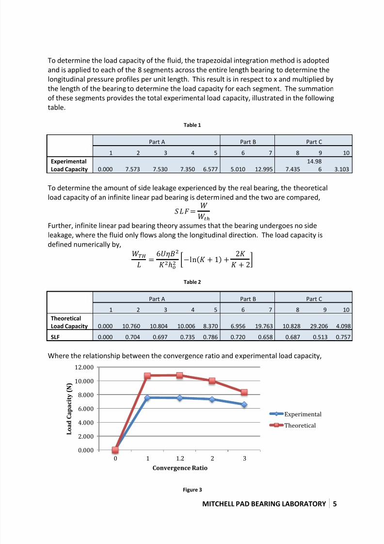
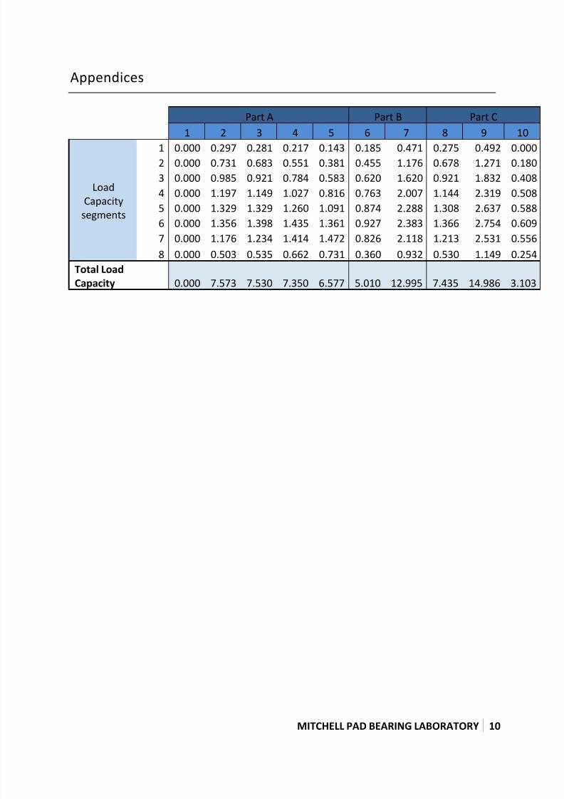
To determine the load capacity of the fluid, the trapezoidal integration method is adopted
and is applied to each of the 8 segments across the entire length bearing to determine the
longitudinal pressure profiles per unit length. This result is in respect to x and multiplied by
the length of the bearing to determine the load capacity for each segment. The summation
of these segments provides the total experimental load capacity, illustrated in the following
table.
Table 1
Part A Part B Part C
1 2 3 4 5 6 7 8 9 10
Experimental
Load Capacity 0.000 7.573 7.530 7.350 6.577 5.010 12.995 7.435
14.98
6 3.103
To determine the amount of side leakage experienced by the real bearing, the theoreticalload capacity of an infinite linear pad bearing is determined and the two are compared,
Further, infinite linear pad bearing theory assumes that the bearing undergoes no side
leakage, where the fluid only flows along the longitudinal direction. The load capacity is
defined numerically by,
[( ) ]
Table 2
Part A Part B Part C
1 2 3 4 5 6 7 8 9 10
Theoretical
Load Capacity 0.000 10.760 10.804 10.006 8.370 6.956 19.763 10.828 29.206 4.098
SLF 0.000 0.704 0.697 0.735 0.786 0.720 0.658 0.687 0.513 0.757
Where the relationship between the convergence ratio and experimental load capacity,
Figure 3
0.000
2.000
4.000
6.000
8.000
10.000
12.000
0 1 1.2 2 3
L o a d
C a p a c i t y ( N )
Convergence Ratio
Experimental
Theoretical
7/27/2019 Mitchell Pad Bearing Experimental Report
http://slidepdf.com/reader/full/mitchell-pad-bearing-experimental-report 6/12
MITCHELL PAD BEARING LABORATORY 6
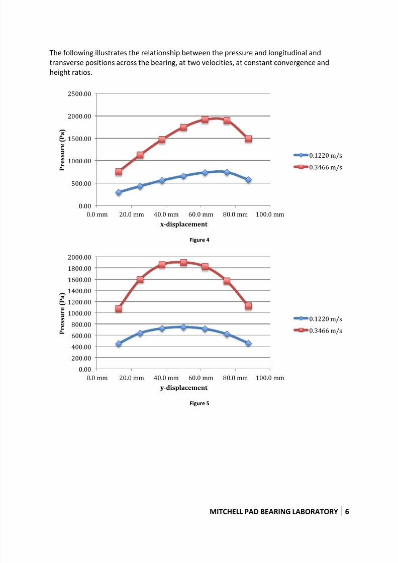
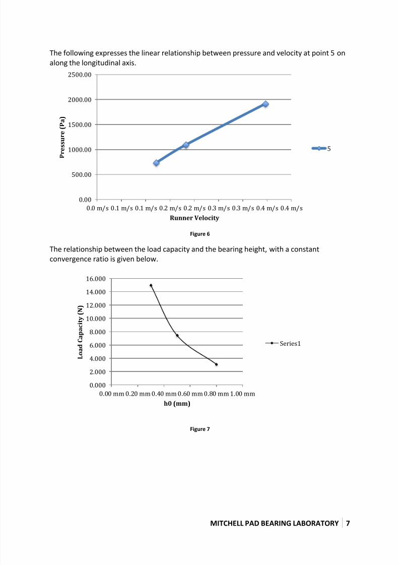
The following illustrates the relationship between the pressure and longitudinal and
transverse positions across the bearing, at two velocities, at constant convergence and
height ratios.
Figure 4
Figure 5
0.00
500.00
1000.00
1500.00
2000.00
2500.00
0.0 mm 20.0 mm 40.0 mm 60.0 mm 80.0 mm 100.0 mm
P r e s s u r e ( P a )
x-displacement
0.1220 m/s
0.3466 m/s
0.00
200.00
400.00
600.00
800.00
1000.00
1200.00
1400.00
1600.00
1800.00
2000.00
0.0 mm 20.0 mm 40.0 mm 60.0 mm 80.0 mm 100.0 mm
P r e s s u r e ( P a )
y-displacement
0.1220 m/s
0.3466 m/s
7/27/2019 Mitchell Pad Bearing Experimental Report
http://slidepdf.com/reader/full/mitchell-pad-bearing-experimental-report 7/12
MITCHELL PAD BEARING LABORATORY 7
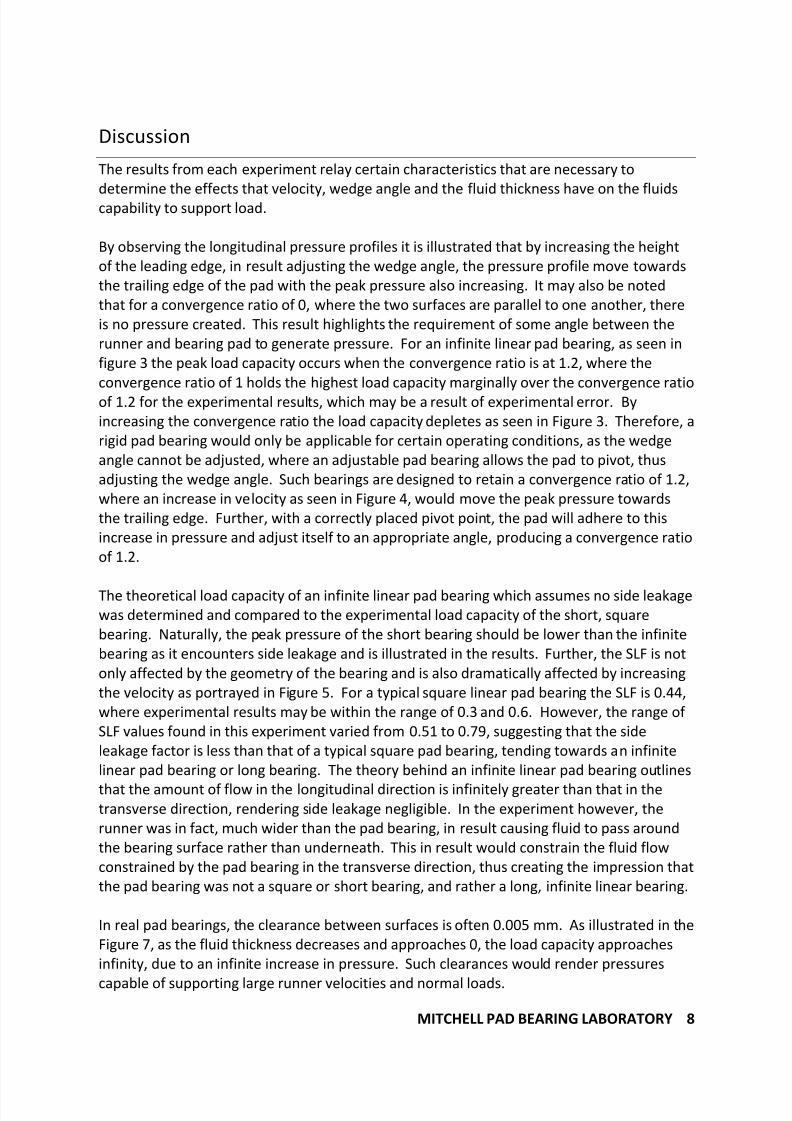
The following expresses the linear relationship between pressure and velocity at point 5 on
along the longitudinal axis.
Figure 6
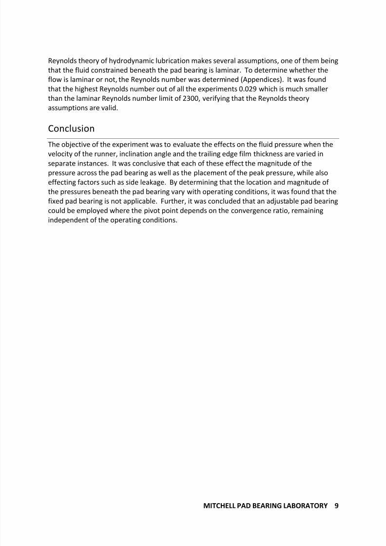
The relationship between the load capacity and the bearing height, with a constant
convergence ratio is given below.
Figure 7
0.00
500.00
1000.00
1500.00
2000.00
2500.00
0.0 m/s 0.1 m/s 0.1 m/s 0.2 m/s 0.2 m/s 0.3 m/s 0.3 m/s 0.4 m/s 0.4 m/s
P r e s s u r e ( P a )
Runner Velocity
5
0.000
2.000
4.000
6.000
8.000
10.000
12.000
14.000
16.000
0.00 mm 0.20 mm 0.40 mm 0.60 mm 0.80 mm 1.00 mm
L o a d
C a p a c i t y ( N )
h0 (mm)
Series1
7/27/2019 Mitchell Pad Bearing Experimental Report
http://slidepdf.com/reader/full/mitchell-pad-bearing-experimental-report 8/12
MITCHELL PAD BEARING LABORATORY 8
Discussion
The results from each experiment relay certain characteristics that are necessary to
determine the effects that velocity, wedge angle and the fluid thickness have on the fluidscapability to support load.
By observing the longitudinal pressure profiles it is illustrated that by increasing the height
of the leading edge, in result adjusting the wedge angle, the pressure profile move towards
the trailing edge of the pad with the peak pressure also increasing. It may also be noted
that for a convergence ratio of 0, where the two surfaces are parallel to one another, there
is no pressure created. This result highlights the requirement of some angle between the
runner and bearing pad to generate pressure. For an infinite linear pad bearing, as seen in
figure 3 the peak load capacity occurs when the convergence ratio is at 1.2, where the
convergence ratio of 1 holds the highest load capacity marginally over the convergence ratio
of 1.2 for the experimental results, which may be a result of experimental error. By
increasing the convergence ratio the load capacity depletes as seen in Figure 3. Therefore, a
rigid pad bearing would only be applicable for certain operating conditions, as the wedge
angle cannot be adjusted, where an adjustable pad bearing allows the pad to pivot, thus
adjusting the wedge angle. Such bearings are designed to retain a convergence ratio of 1.2,
where an increase in velocity as seen in Figure 4, would move the peak pressure towards
the trailing edge. Further, with a correctly placed pivot point, the pad will adhere to this
increase in pressure and adjust itself to an appropriate angle, producing a convergence ratio
of 1.2.
The theoretical load capacity of an infinite linear pad bearing which assumes no side leakage
was determined and compared to the experimental load capacity of the short, square
bearing. Naturally, the peak pressure of the short bearing should be lower than the infinite
bearing as it encounters side leakage and is illustrated in the results. Further, the SLF is not
only affected by the geometry of the bearing and is also dramatically affected by increasing
the velocity as portrayed in Figure 5. For a typical square linear pad bearing the SLF is 0.44,
where experimental results may be within the range of 0.3 and 0.6. However, the range of
SLF values found in this experiment varied from 0.51 to 0.79, suggesting that the side
leakage factor is less than that of a typical square pad bearing, tending towards an infinite
linear pad bearing or long bearing. The theory behind an infinite linear pad bearing outlines
that the amount of flow in the longitudinal direction is infinitely greater than that in thetransverse direction, rendering side leakage negligible. In the experiment however, the
runner was in fact, much wider than the pad bearing, in result causing fluid to pass around
the bearing surface rather than underneath. This in result would constrain the fluid flow
constrained by the pad bearing in the transverse direction, thus creating the impression that
the pad bearing was not a square or short bearing, and rather a long, infinite linear bearing.
In real pad bearings, the clearance between surfaces is often 0.005 mm. As illustrated in the
Figure 7, as the fluid thickness decreases and approaches 0, the load capacity approaches
infinity, due to an infinite increase in pressure. Such clearances would render pressures
capable of supporting large runner velocities and normal loads.
7/27/2019 Mitchell Pad Bearing Experimental Report
http://slidepdf.com/reader/full/mitchell-pad-bearing-experimental-report 9/12
MITCHELL PAD BEARING LABORATORY 9
Reynolds theory of hydrodynamic lubrication makes several assumptions, one of them being
that the fluid constrained beneath the pad bearing is laminar. To determine whether the
flow is laminar or not, the Reynolds number was determined (Appendices). It was found
that the highest Reynolds number out of all the experiments 0.029 which is much smaller
than the laminar Reynolds number limit of 2300, verifying that the Reynolds theory
assumptions are valid.
Conclusion
The objective of the experiment was to evaluate the effects on the fluid pressure when the
velocity of the runner, inclination angle and the trailing edge film thickness are varied in
separate instances. It was conclusive that each of these effect the magnitude of the
pressure across the pad bearing as well as the placement of the peak pressure, while also
effecting factors such as side leakage. By determining that the location and magnitude of
the pressures beneath the pad bearing vary with operating conditions, it was found that thefixed pad bearing is not applicable. Further, it was concluded that an adjustable pad bearing
could be employed where the pivot point depends on the convergence ratio, remaining
independent of the operating conditions.
7/27/2019 Mitchell Pad Bearing Experimental Report
http://slidepdf.com/reader/full/mitchell-pad-bearing-experimental-report 10/12
MITCHELL PAD BEARING LABORATORY 10
Appendices
Part A Part B Part C
1 2 3 4 5 6 7 8 9 10
Load
Capacity
segments
1 0.000 0.297 0.281 0.217 0.143 0.185 0.471 0.275 0.492 0.000
2 0.000 0.731 0.683 0.551 0.381 0.455 1.176 0.678 1.271 0.180
3 0.000 0.985 0.921 0.784 0.583 0.620 1.620 0.921 1.832 0.408
4 0.000 1.197 1.149 1.027 0.816 0.763 2.007 1.144 2.319 0.508
5 0.000 1.329 1.329 1.260 1.091 0.874 2.288 1.308 2.637 0.588
6 0.000 1.356 1.398 1.435 1.361 0.927 2.383 1.366 2.754 0.609
7 0.000 1.176 1.234 1.414 1.472 0.826 2.118 1.213 2.531 0.556
8 0.000 0.503 0.535 0.662 0.731 0.360 0.932 0.530 1.149 0.254
Total Load
Capacity 0.000 7.573 7.530 7.350 6.577 5.010 12.995 7.435 14.986 3.103

7/27/2019 Mitchell Pad Bearing Experimental Report
http://slidepdf.com/reader/full/mitchell-pad-bearing-experimental-report 11/12
MITCHELL PAD BEARING LABORATORY 1
1
Part A Part B Part C
Test Number 1 2 3 4 5 6 7 8 9 10
1 0.50 mm 1.00 mm 1.10 mm 1.50 mm 2.00 mm 1.10 mm 1.10 mm 1.10 mm 0.66 mm 1.76 mm
0 0.50 mm 0.50 mm 0.50 mm 0.50 mm 0.50 mm 0.50 mm 0.50 mm 0.50 mm 0.30 mm 0.80 mm
(h1/h0) 1 2 2.2 3 4 2.2 2.2 2.2 2.2 2.2
(h1-h0)/h0 0 1 1.2 2 3 1.2 1.2 1.2 1.2 1.2
0.1876 m/s 0.1832 m/s 0.1824 m/s 0.1830 m/s 0.1823 m/s 0.1220 m/s 0.3466 m/s 0.1828 m/s 0.1775 m/s 0.1840 m/s
24.50 °C 24.50 °C 24.50 °C 24.50 °C 24.50 °C 25.00 °C 25.00 °C 24.50 °C 24.50 °C 25.00 °C
0.09 Pas 0.09 Pas 0.09 Pas 0.09 Pas 0.09 Pas 0.09 Pas 0.09 Pas 0.09 Pas 0.09 Pas 0.09 Pas
107.00 cSt 107.00 cSt 107.00 cSt 107.00 cSt 107.00 cSt 103.00 cSt 103.00 cSt 107.00 cSt 107.00 cSt 103.00 cSt
M a n o m e t e r H e i g h t s / P
r e s s u r e
x d i r e c t i o n
1 12.5 mm 0 0 56 474.48 53 449.06 41 347.39 27 228.77 35 296.55 89 754.09 52 440.59 93 787.98 0 0.00
2 25.0 mm 0 0 82 694.78 76 643.94 63 533.79 45 381.28 51 432.12 133 1126.90 76 643.94 147 1245.52 34 288.08
3 37.5 mm 0 0 104 881.18 98 830.34 85 720.20 65 550.74 66 559.21 173 1465.81 98 830.34 199 1686.11 43 364.33
4 50.0 mm 0 0 122 1033.69 119 1008.27 109 923.55 89 754.09 78 660.89 206 1745.42 118 999.80 239 2025.02 53 449.06
5 62.5 mm 0 0 129 1093.00 132 1118.42 129 1093.00 117 991.33 87 737.14 226 1914.87 129 1093.00 259 2194.48 58 491.43
6 75.0 mm 0 0 127 1076.06 132 1118.42 142 1203.15 140 1186.21 88 745.61 224 1897.93 129 1093.00 261 2211.43 57 482.96
7 87.5 mm 0 0 95 804.93 101 855.76 125 1059.11 138 1169.26 68 576.16 176 1491.23 100 847.29 217 1838.62 48 406.70
y d i r e c t i o n
8 12.5 mm 0 0 75 635.47 77 652.41 84 711.72 85 720.20 53 449.06 127 1076.06 76 643.94 139 1177.73 36 305.02
9 25.0 mm 0 0 109 923.55 113 957.44 123 1042.17 124 1050.64 75 635.47 188 1592.90 110 932.02 209 1770.84 51 432.12
10 37.5 mm 0 0 122 1033.69 129 1093.00 139 1177.73 139 1177.73 85 720.20 219 1855.56 126 1067.59 250 2118.22 57 482.96
11 50.0 mm 0 0 127 1076.06 132 1118.42 142 1203.15 140 1186.21 88 745.61 224 1897.93 129 1093.00 261 2211.43 57 482.96
12 62.5 mm 0 0 122 1033.69 126 1067.59 136 1152.31 132 1118.42 84 711.72 215 1821.67 124 1050.64 254 2152.12 55 466.01
13 75.0 mm 0 0 105 889.65 109 923.55 118 999.80 114 965.91 73 618.52 185 1567.49 107 906.60 213 1804.73 48 406.70
14 87.5 mm 0 0 76 643.94 79 669.36 84 711.72 81 686.30 54 457.54 132 1118.42 77 652.41 160 1355.66 35 296.55
Maximum
x direction 0.00 1093.00 1118.42 1203.15 1186.21 745.61 1914.87 1093.00 2211.43 491.43
y direction 0.00 1076.06 1118.42 1203.15 1186.21 745.61 1897.93 1093.00 2211.43 482.96
Fluid PropertiesGeometry
B 100.0 mm
Density @ 15°C 863.7 L 100.0 mm
Reynolds Number 0.004 0.010 0.011 0.017 0.027 0.011 0.004 0.029 0.008 0.022

7/27/2019 Mitchell Pad Bearing Experimental Report
http://slidepdf.com/reader/full/mitchell-pad-bearing-experimental-report 12/12
MITCHELL PAD BEARING LABORATORY 1
2
Top Related