


Languages
Pages
Legal


13th ANNUAL MDEC CONFERENCE Sheraton Parkway, Toronto North, Canada
October 1 – 5, 2007
MDEC SHORT COURSE ON
ENGINE AND DPF TECHNOLOGY PRESENTED BY: KUBOTA, ECS, DCL & CEP
COORDINATED BY: MAHE GANGAL, NRCan
OCTOBER 2, 2007
M I N I N G D I E S E L E M I S S I O N S C O U N C I L

Diesel Workshop
MDEC Short Course on Engine and DPF Technology
Sheraton Parkway, Toronto North Ontario, Canada
Markham Room
Tuesday, October 2, 2007
08:00 – 08:30 Registration & Gathering (Coffee available) 08:30 – 10:00 Welcome (Mahe Gangal, Co-chair MDEC Conference) Engine Technology
• Combustion Fundamentals, Fuels, & Emissions (John Baxter, Kubota Canada Ltd)
10:00 – 10:30 Coffee Break 10:30 – 12:00 Engine Technology
• Service & Maintenance (Walter Steffler, Kubota Canada Ltd) • Discussion & Conclusion
12:00 – 13:00 Lunch (Markham Room) 13:00 – 14:30 DPF Technology
• Fundamentals (Glen Prisciak, DCL International Inc.) • Selection & Sizing (Ted Tadrous, Engine Control System Limited)
14:30 – 15:00 Coffee Break
15:00 – 16:30 DPF Technology
• Retrofit & Operation (Don Malgast, Engine Control Systems Limited) • Maintenance (John Stekar, Catalytic Exhaust Products Limited) • Discussion & Conclusion
M I N I N G D I E S E L E M I S S I O N S C O U N C I L

Diesel Workshop
MDEC Short Course on Engine and DPF Technology
Sheraton Parkway, Toronto North Ontario, Canada
Tuesday, October 2, 2007
CONTENTS
Contents Diesel Workshop Course Agenda Diesel Workshop Sections List Registration List Section 1 Engine Technology - Combustion Fundamentals, Fuels, & Emissions
(John Baxter, Kubota Canada Ltd)
Section 2 Engine Technology - Service & Maintenance (Walter Steffler, Kubota Canada Ltd)
Section 3 DPF Technology - Fundamentals
(Glen Prisciak, DCL International Inc.)
Section 4 DPF Technology - Selection & Sizing (Ted Tadrous, Engine Control System Limited)
Section 5 DPF Technology - Retrofit & Operation
(Don Malgast, Engine Control Systems Limited)
Section 6 DPF Technology - Maintenance (John Stekar, Catalytic Exhaust Products Limited)
M I N I N G D I E S E L E M I S S I O N S C O U N C I L

Workshop MDEC - 2007
Registration Address List
Cheryl Allen Bus: (705) 682-6857 Sr. Ventilation Eng. email: [email protected] CVRD - INCO 18 Rink Street Copper Cliff, Ontario P0M 1N0 Aleksandar Bugarski Bus: (412) 386-5912 Mechanical Engineer Fax: (412) 386-4917 NIOSH - PRL email: [email protected] 626 Cochrans Mill Rd. Pittsburgh, PA USA 15236 Peter Burrell Bus: (705) 566-5438 Service Planner Fax: (705_ 566-5422 Tracks & Wheels Equipment Brokers Inc. email: [email protected] 400 Hwy. 69 PO Box 2592 Sudbury, Ontario P3A 4S9 Gerald Carmichael Bus: (204) 687-4448 Vice President Fax: (204) 687 8176 United Steelworkers Local 7106 email: [email protected] 68 Church St., Flin Flon, Manitoba R8A 1K7 Emanuele Cauda Bus: (412) 386-4518 Research Engineer Fax: (412) 386-4917 NIOSH PRL email: [email protected] 626 Cochrans Mill Rd., Pittsburgh, PA USA 15236 Aldo Cerilli Bus: (705) 682-5037 Worker Rep South Mine email: [email protected] CVRD - INCO Copper Cliff Sudbury, Ontario P3E 6G8 Bob Clayton Bus: (713) 682-3651 Business Development Manager Fax: (713) 682-1109 T.F. Hudgins Inc. email: [email protected] PO Box 920946 Houston, Texas USA 77292-0946

Manfred Duering Bus: +49-6152-174112 Cummins Deutschland GmbH Fax: +49-6152-174141 Odenwaldstrasse 23 email: [email protected] Gross Gerau, Germany 64521 Sanjeev K. Duggal Bus: (812) 373-7645 Manager Mining Business Fax: (812) 377-1667 Cummins Inc. email: [email protected] 560 Jackson St., Columbas, Indiana Steve Fedrizzi Bus: (607) 533-4221 Maintenance Supervisor Fax: (607) 533-4501 Cargill Deicing Technology email: [email protected] 191 Portland Point Road Lansing, New York USA 14882 Steve Forbush email: [email protected] Diesel Equipment Specialist Arch Coal Inc. PO Box 240, Aurora Utah USA 84620 John Ford Bus: (607) 533-4221 Maintenance Technician Fax: (607) 533-4501 Cargill Deicing Technology 191 Portland Point Road Lansing, New York USA 14822 Mattias Forssén Bus: +45 3132 21621 Engineer email: [email protected] Volvo Penta Corp Gropegardsgatan Gothenburg, Sweden 4175 Sean Gannon Bus: (607) 533-4221 Mechanical Engineer Fax: (607) 533-4501 Cargill Deicing Technology email: [email protected] 191 Portland Point Road Lansing, New York USA 14822 David Griffiths Bus: 996-3411 Sr. Technologist Fax: 996-6590 Xstrata Nickel - Sudbury Mines/Mill email: [email protected] Strathcona Complex Onaping, Ontario P0M 2R0

Kevin Hinds GF Mobile CVRD - INCO Jeff Jacobs Bus: (860) 658-3438 Region Manager email: [email protected] Caterpillar 175 Power Forest Dr. Weatogue, CT USA 06089 Kenneth Jokela Bus: (705) 560-7820 OHSE CVRD - INCO 1991 Springdale Sudbury, Ontario P3A 4H9 Seppo Karhu Bus: +358 20544 5220 Sandvik Mining and Construction Fax: +358 20544 5555 Vahdontie 19, PO Box 434 email: [email protected] Turku, Finland 20101 Kevin G. Kroger Bus: (561) 547-9499 President Fax: (561) 547-8629 Puradyn Filter email: [email protected] 2017 High Ridge Rd., Baynton Beach, Florida USA 33467 Alain Landry Bus: (705) 966-3411 Mobile Maintenance Co-Ordinator Fax: (705) 966-6560 Xstrata Nickel email: [email protected] Craig Mine Onaping, Ontario P0M 2R0 George Larouche Bus: (705) 566-2561 HBET email: [email protected] CVRD - INCO 60 Mine Rd., Garson Ontario P3L 1N6 James McClintock Bus: (519) 972-2211 Mine Engineer Fax: (519) 972-1777 CSCL Ojibway Mine email: jmcclintock@windsorsalt .com 200 Morton Dr., Windsor, Ontario N9J 3W9

Ray Marsh Bus: (607) 533-4221 Maintenance Technician Fax: (607) 533-4501 Cargill Deicing Technology 191 Portland Point Road Lansing, New York USA 14882 Shawn Matthews Bus: (705) 693-3022 Worker Safety Rep. email: [email protected] CVRD - INCO 54 Monique Cres., Garson, Ontario P3L 1C6 Colin Morrish Bus: (306) 933-7594 Mines Inspector Fax: (306) 933-7339 Saskatchewan Labour email: [email protected] 122-3rd Avenue North Saskatoon, Sk S7K 6A5 Richard Paquin Bus: (705) 673-3661 Xstrata Nickel - Unit Chair Fax: (705) 673-1183 Mine Mill- Local 598 email: 19 Regent St., S. Sudbury, Ontario P3C 4B7 Peter Saal Bus: (705) 675-3503 Chair, Health, Safety & Env. Committee Fax: (705) 675-2438 Local 6500 United Steelworkers email: [email protected] 92 Frood Road Sudbury, Ontario P3C 4Z4 Mike St. Onge Bus: (705) 983-5556 Worker Rep. Fax: (705) 966-4114 CVRD - INCO email: [email protected] 300 Brobant Street Azilda, Ontario P0M 1B0 Brent Salem Bus: (705) 693-4906 General Forman email: [email protected] CVRD - INCO 848 St. Andrews Sudbury, Ontario P3A 3W7 George H. Schnakenberg, Jr. Bus: (412) 386-6655 Research Physicist Fax: (412) 386-4917 NIOSH - PRL email: [email protected] 626 Cochrans Mill Rd., Pittsburgh, PA USA 15236
Kevin Schutt Bus: (705) 525-3330 Maintenance Forman Fax: (705) 525-3271 CVRD- INCO email: [email protected] 143 Gordon St. Garson, Ontario P3L 1N1 Bill Spelliscy Bus: (204) 687-4448 Treasurer - Health and Safety Co-Chair Fax: (204) 687-8176 United Steelworkers Local 7106 email: [email protected] 68 Church St., Flin Flan, Manitoba R8A 1K7 Glen Staskus Bus:(705) 966-3411 Health & Safety Coordinator Bus: (705) 966-6560 Xstrata Nickel - Craig Mine email: [email protected] Onaping Ontario P0M 2R0 Daniel Stinnette Bus: (559) 452-0182 Engineer Fax: (559) 452-0184 Mine Ventilation Services Inc. email: [email protected] 4946 E. Yale Ave., Suite 103 Fresno Ca USA 93727 Karsten Taudte Bus: +49-6152-174187 Cummins Deutschland GbmH Fax: +49-6152-174141 Odenwaldstrasse 23 email: [email protected] Gross-Gerau, Germany 64521 Alan Thibert Bus: (519) 646-3235 Mining Health & Safety Inspector Fax: (519) 672-0268 Ministry of Labour email: [email protected] 217 York st., 5th Floor London, Ontario Frank Woit Bus: (705) 474-9196 Field Consultant Fax: (705) 472-5800 Mines & Aggregates Safety & Health Assn. email: [email protected] 690 McKeown Ave North Bay, Ontario P1B 9P1

1
Welcome to MDEC Workshop
John BaxterEngineering Manager - Engine
Kubota Canada Ltd
Tuesday 2nd October 2007
2
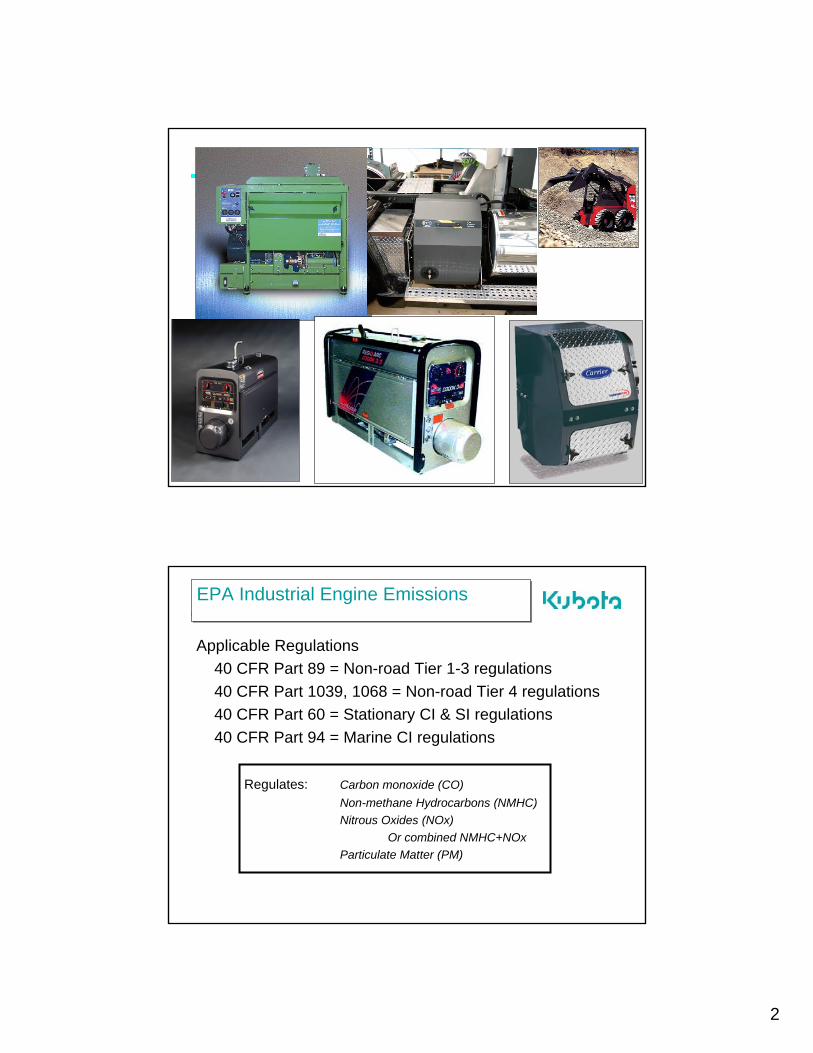
EPA Industrial Engine EmissionsEPA Industrial Engine Emissions
Applicable Regulations40 CFR Part 89 = Non-road Tier 1-3 regulations40 CFR Part 1039, 1068 = Non-road Tier 4 regulations40 CFR Part 60 = Stationary CI & SI regulations40 CFR Part 94 = Marine CI regulations
Regulates: Carbon monoxide (CO)Non-methane Hydrocarbons (NMHC) Nitrous Oxides (NOx)
Or combined NMHC+NOxParticulate Matter (PM)
3
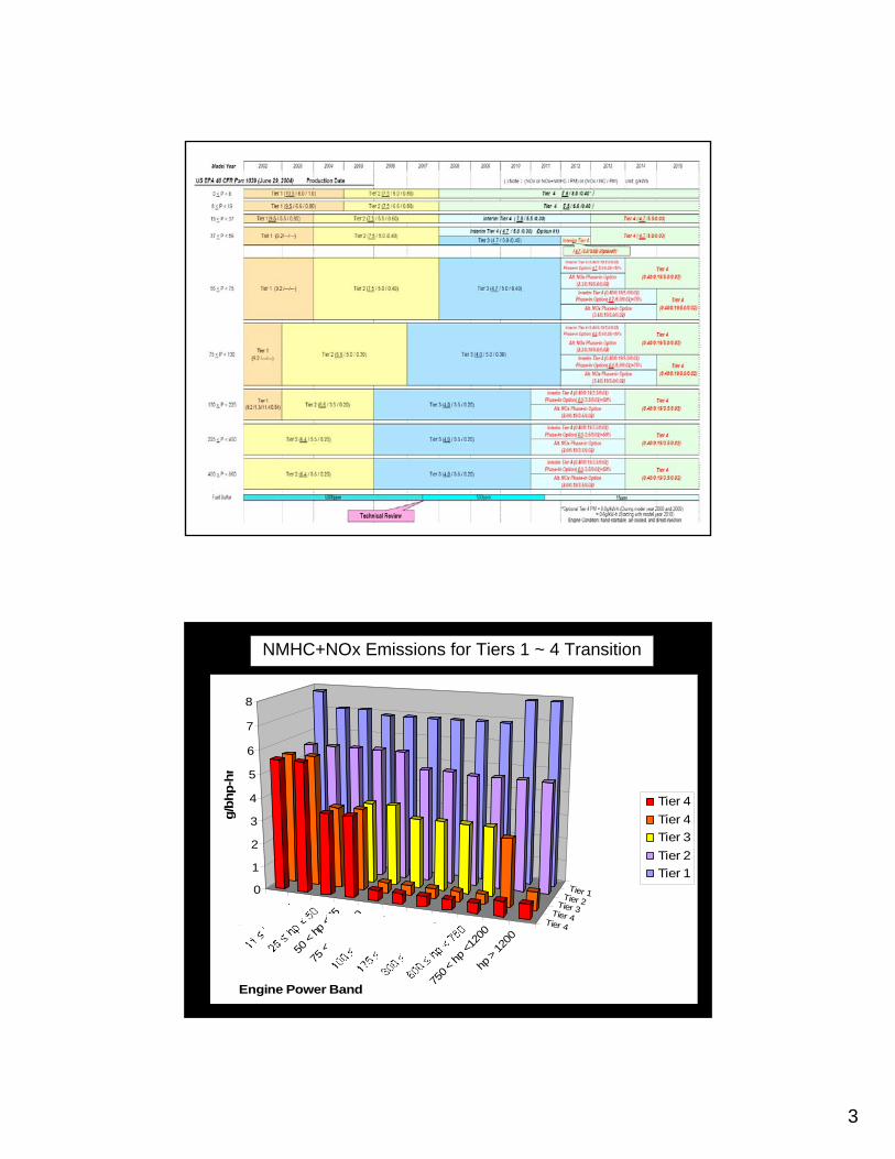
NMHC+NOx Emissions for Tiers 1 ~ 4 Transition
hp <
11
50 <
hp <7
5
75 <
hp <
100
750 <
hp <1
200
hp > 12
00Tier 4
Tier 4Tier 3
Tier 2Tier 10
1
2
3
4
5
6
7
8
g/bh
p-hr
Engine Power Band
Tier 4Tier 4Tier 3Tier 2Tier 1
4
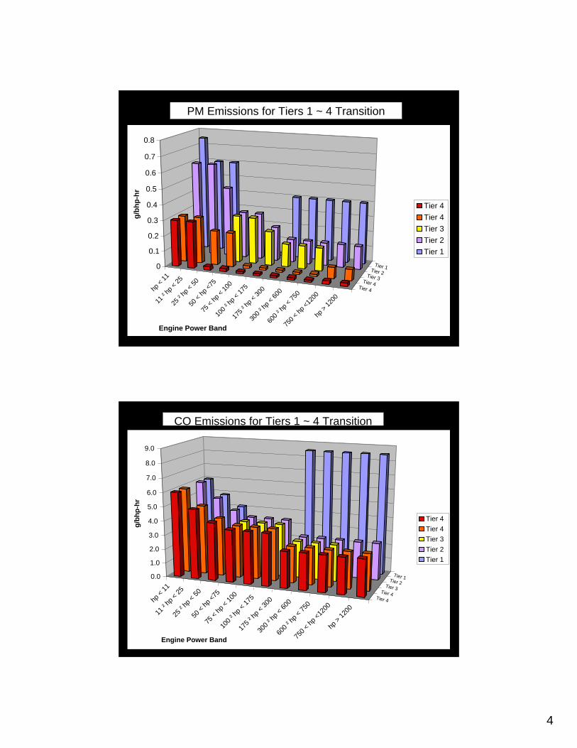
PM Emissions for Tiers 1 ~ 4 Transition
hp <
11
11 ² h
p < 25
25 ² h
p < 50
50 <
hp <7
5
75 <
hp <
100
100 ²
hp <
175
175 ²
hp <
300
300 ²
hp <
600
600 ²
hp <
750
750 <
hp <1
200
hp >
1200
Tier 4Tier 4
Tier 3Tier 2
Tier 10
0.1
0.2
0.3
0.4
0.5
0.6
0.7
0.8g/
bhp-
hr
Engine Power Band
Tier 4Tier 4Tier 3Tier 2Tier 1
CO Emissions for Tiers 1 ~ 4 Transition
hp <
11
11 ² h
p < 25
25 ² h
p < 50
50 <
hp <7
5
75 <
hp <
100
100 ²
hp <
175
175 ²
hp <
300
300 ²
hp <
600
600 ²
hp <
750
750 <
hp <1
200
hp >
1200
Tier 4
Tier 4Tier 3
Tier 2Tier 10.0
1.0
2.0
3.0
4.0
5.0
6.0
7.0
8.0
9.0
g/bh
p-hr
Engine Power Band
Tier 4Tier 4Tier 3Tier 2Tier 1
5
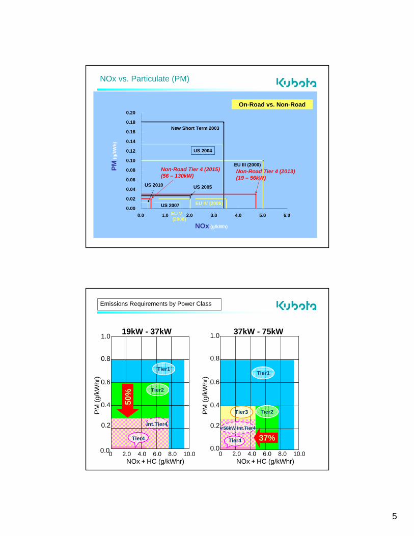
NOx vs. Particulate (PM)
0.00
0.02
0.04
0.06
0.08
0.10
0.12
0.14
0.16
0.18
0.20
0.0 1.0 2.0 3.0 4.0 5.0 6.0
PM(g
/kW
h)
NOx (g/kWh)
EU III (2000)
US 2010
US 2004
US 2007 EU IV (2005)
EU V(2008)
New Short Term 2003
US 2005
Non-Road Tier 4 (2013)(19 – 56kW)
Non-Road Tier 4 (2015)(56 – 130kW)
On-Road vs. Non-Road
Emissions Requirements by Power Class
19kW - 37kW
NOx+HC (g/kWhr)0 2.0 4.0 6.0 8.0 10.00.0
0.2
0.4
0.6
0.8
1.0
PM (g
/kW
hr)
37kW - 75kW
NOx+HC (g/kWhr)0 2.0 4.0 6.0 8.0 10.0
0.0
0.2
0.4
0.6
0.8
1.0
PM (g
/kW
hr)
Tier2
Tier1
Tier2
Int.Tier4
Tier3
<56kW Int.Tier4
Tier4 Tier4 37%
50%
Tier1

6
Possible Solutions to meet EPA Regulations
kW 03 04 05 06 07 08 09 10 11 12 13 14
Tier IV
Engine Optimization (same engine outline)
Engine Optimization (same engine outline)
Tier III and Int. Tier IV
Tier III Technologies +
EGR + DPF
Common Rail System & EGR + DPF & NOx
CatalystCommon Rail System & EGR
Engine Optimization + EGR + Additional Device(s)
75<
Tier ITier II
Engine Optimization and Closed
Breather system (same engine outline)
<19
19-37
37-56
56-75
Tier 4 Standards for CI< 19 kW (25 hp)Tier 4 Standards for CI< 19 kW (25 hp)
Effective Effective -- 20082008
<19kW (Tier 4) Focus = reduction of PM 50%(Other emissions same as Tier 2)
Internal engine optimization can be utilized
No need for exhaust after-treatment
EPA technology review to take place in 2007

7
Tier 4 Standards for CI< 19 kW (25 hp)Tier 4 Standards for CI< 19 kW (25 hp)
kW 03 04 05 06 07 08 09 10 11 12 13 14
Engine Optimization (same engine outline)
<19
Solutions to meet EPA Regulations
Engine Optimization and Closed
Breather system
・ Shape optimization
Modification Items of <19kW for Tier 4i
Combustion chamber
Minimize Production Tolerances Optimized Oil Consumption
Piston
・ Recess shape optimization
Intake / Exhaust Valve
・ Face shape Optimization
Same Engine OutlineSame Engine Outline

8
D905D722 D902
Pistons

9
Tier 3 – Interim Tier 4 Standards for CI19 ≤ kW < 37 (25 ≤ hp < 50)Tier 3 – Interim Tier 4 Standards for CI19 ≤ kW < 37 (25 ≤ hp < 50)
Effective Effective -- 2008 2008 19~37kW (Int. Tier 4) Focus = reduction of PM 50% (Other emissions same as Tier 2)
Possible Solutions to meet EPA Regulations
kW 03 04 05 06 07 08 09 10 11 12 13 14
Tier IV
Engine Optimization (same engine outline)
Engine Optimization (same engine outline)
Tier III and Int. Tier IV
Tier III Technologies +
EGR + DPF
Common Rail System & EGR + DPF & NOx
CatalystCommon Rail System & EGR
Engine Optimization + EGR + Additional Device(s)
75<
Tier ITier II
Engine Optimization and Closed
Breather system (same engine outline)
<19
19-37
37-56
56-75

10
Modification Items of 19~37kW for Tier 4i
Boost compensator (R-24 only)
(Turbo engine only)
Closed breather
(Turbo engines) ・ Shape optimization
Combustion chamber
Minimize Production Tolerances
Optimized Oil Consumption
Piston
・ Recess shape optimization
Intake / Exhaust Valve
・ Face shape optimization
Same Engine OutlineSame Engine Outline
Thermostat
Actuator
Decrease
Boost Compensator
20
EU - R-24Emissionsrequirement
Control Rack
Increase

11
Closed Breather System
Tier 3 – Interim Tier 4 Standards for CI37 ≤ kW < 56 (50 ≤ hp < 75)Tier 3 – Interim Tier 4 Standards for CI37 ≤ kW < 56 (50 ≤ hp < 75)
Effective Effective -- 2008 2008
37~56kW (TWO PATHS!) Focus =Option 1 = Interim Tier 4 –
reduce NMHC+NOx by 37%, PM levels by 25% (CO emissions same as Tier 2)
Interim Tier 4 sunsets at end of 2012
Option 2 = Tier 3 –reduce NMHC+NOx by 37% PM levels same as Tier 2
(Other emissions same as Tier 2)Tier 3 sunsets at end of 2011
Exhaust afterExhaust after--treatment required one whole year earlier with option 2treatment required one whole year earlier with option 2PM reduction requires use of Low Sulfur Diesel fuel (< 500 ppm) from June 2007 (nonroad applications)

12
Possible Solutions to meet EPA Regulations
kW 03 04 05 06 07 08 09 10 11 12 13 14
Tier IV
Engine Optimization (same engine outline)
Engine Optimization (same engine outline)
Tier III and Int. Tier IV
Tier III Technologies +
EGR + DPF
Common Rail System & EGR + DPF & NOx
CatalystCommon Rail System & EGR
Engine Optimization + EGR + Additional Device(s)
75<
Tier ITier II
Engine Optimization and Closed
Breather system (same engine outline)
<19
19-37
37-56
56-75
13
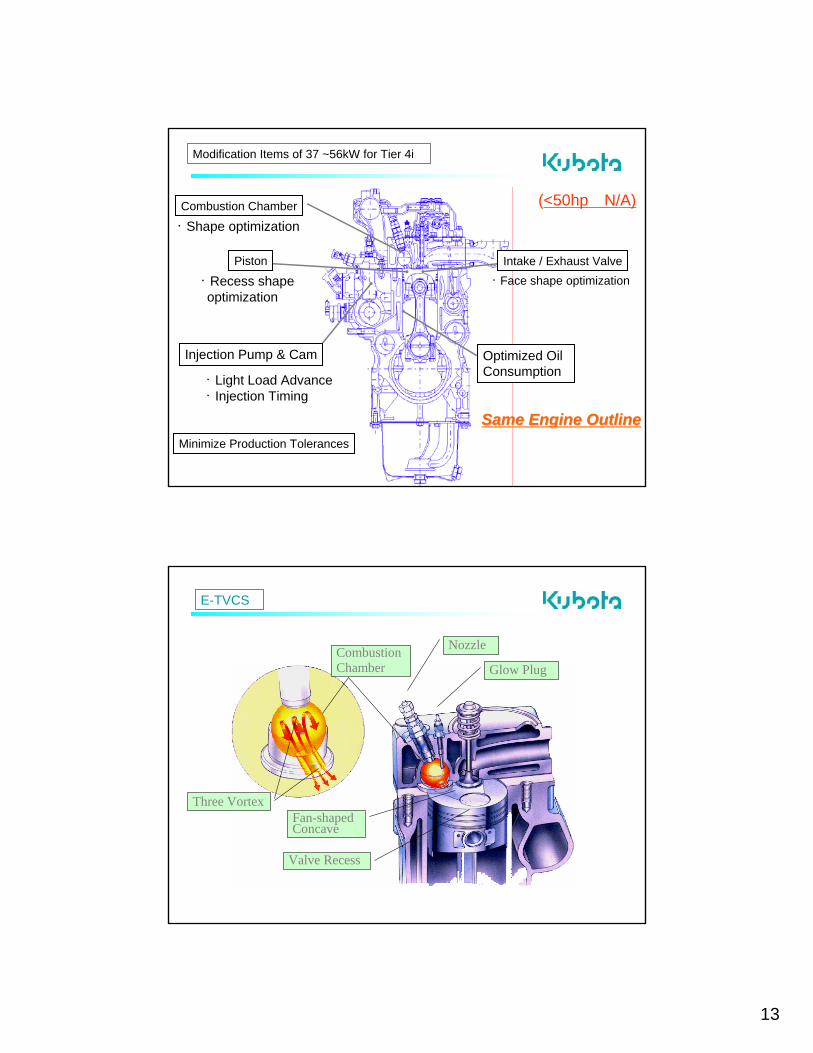
Modification Items of 37 ~56kW for Tier 4i
・ Light Load Advance・ Injection Timing
Injection Pump & Cam
(<50hp N/A)・ Shape optimization Combustion Chamber
Minimize Production Tolerances
Optimized Oil Consumption
Piston
・ Recess shape optimization
Intake / Exhaust Valve・ Face shape optimization
Same Engine OutlineSame Engine Outline
E-TVCS
Glow Plug
Nozzle
Three VortexFan-shaped Concave
Valve Recess
Combustion Chamber

14
PFR Injection Pump with Fine Spill Port

15
Current Hollow Chamber
Piston Temp.250C 225C
275CPiston Temp.
225C 250C275C
Hollow Chamber
29
Thermostat
Control Type Thermostat & Bottom Bypass System
tem
pera
ture
(°C
)
standard thermostat
bottom Bypass thermostat

16
Same Outline as V2403-M, with Turbo Charger No EGR required
V2403-M-IDI-T
New 03M Model
New V3600 Model
Same Outline as V3300-NA(IDI), with few minor changes – No EGR required
V3600-T (IDI)
Same Outline as V3300-NA(IDI), with few minor changes – No EGR required
V3600-NA (IDI)
17
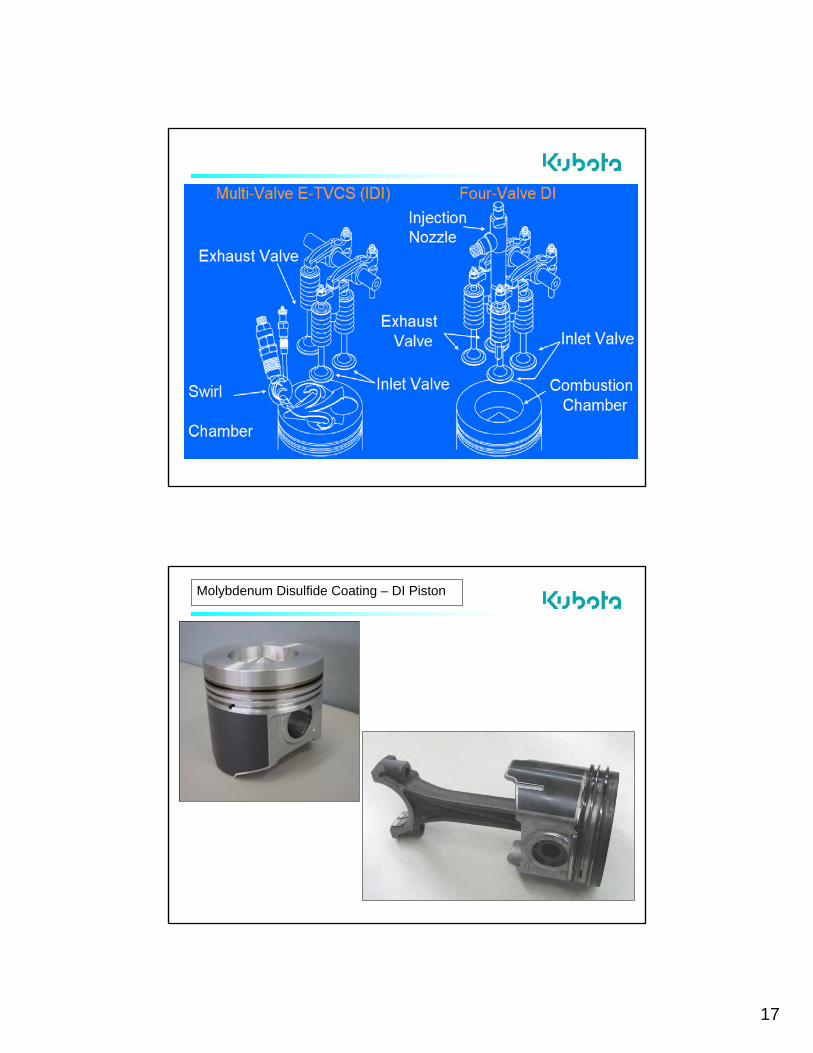
Molybdenum Disulfide Coating – DI Piston
18
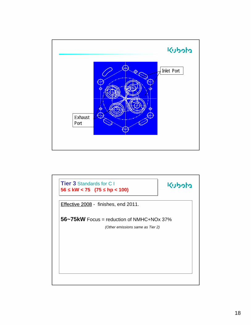
Inlet Port
Exhaust Port
Tier 3 Standards for C I56 ≤ kW < 75 (75 ≤ hp < 100)Tier 3 Standards for C I56 ≤ kW < 75 (75 ≤ hp < 100)
Effective 2008Effective 2008 - finishes, end 2011.
56~75kW Focus = reduction of NMHC+NOx 37%(Other emissions same as Tier 2)

19
Solutions for Tier3 – 56~75kW
Cooled EGR System
Optimized Piston Profile & Cyl. Liner
Double Element Type Intake Heater
Higher Pressure Injection System
Mechanical Timer with Cold Advanced function
Tighter Production Tolerance
Boost Compensator for
EU - R24

20
37-75kW Tier 1 (NOx)
0
0.2
0.4
0.6
0.8
0.0 2.0 4.0 6.0 8.0 10.0NOx+HC (g/kW・h)
PM
(g/k
W・h
)
37-75kW Tier 2 (2004)
Tier 3 engine
Tier 2 Models
37-56kW Int tier 4 (2008)
DI (37≦P<75kW)
Effect of Combustion Chamber Shape

21
Port2
Port1Two Inlet PortSwirl & DirectPort
One Exhaust Port
Water Channel between Exhaust Valves
Inlet Port
Exhaust Port
Port 2
Port 1
Mechanical (Speed) Timer
Centrifugal Force
Centrifugal Force
Rotation direction
Advance
22
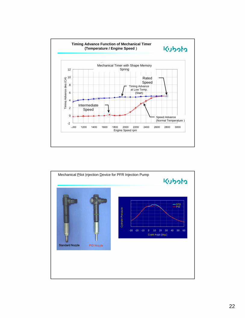
Timing Advance Function of Mechanical Timer(Temperature / Engine Speed)
形状記憶バネ メカタイマー(A56G3ーDI)
-1
0
1
2
3
4
5
6
1000 1200 1400 1600 1800 2000 2200 2400 2600 2800 3000エンジン回転速度rpm
タイマー
進角
℃A
Speed Advance (Normal Temperature)
Timing Advance at Low Temp.
(Start)
Intermediate Speed
Engine Speed rpm
Tim
ing
Adva
nce
deg
(CA)
Mechanical Timer with Shape Memory Spring
RatedSpeed
-2
0
2
4
6
8
10
12
Standard Nozzle PID Nozzle
Mechanical Pilot Injection Device for PFR Injection Pump
010002000300040005000600070008000
-30 -20 -10 0 10 20 30 40 50 60Crank Angle [deg.]
Cyl
inde
r Pre
ssur
e [k
Pa]
STDPID

23
Operating Principal of PID
PID:Valve closed
Piston
Injection Rate
Pressure on Nozzle side
Nozzle opening pressureNozzle closing pressure
Valve open
Pilot Injection Main Injection
Principle of Mechanical Pilot Injection
0
0.2
0.4
0.6
0.8
0.0 2.0 4.0 6.0 8.0 10.0NOx+HC (g/kW・h)
PM
(g/k
W・h
)
37-75kW Tier 2 (2004)
Tier 2 Models
Improvement ofCombustion and Injection SystemEGR
37-75kW Tier 1 (NOx)
DI (37≦P<75kW)
37-56kW Int Tier 4 (2008)
37-75kW Tier 3 (2008) “E2” Models
“E3” engine
24
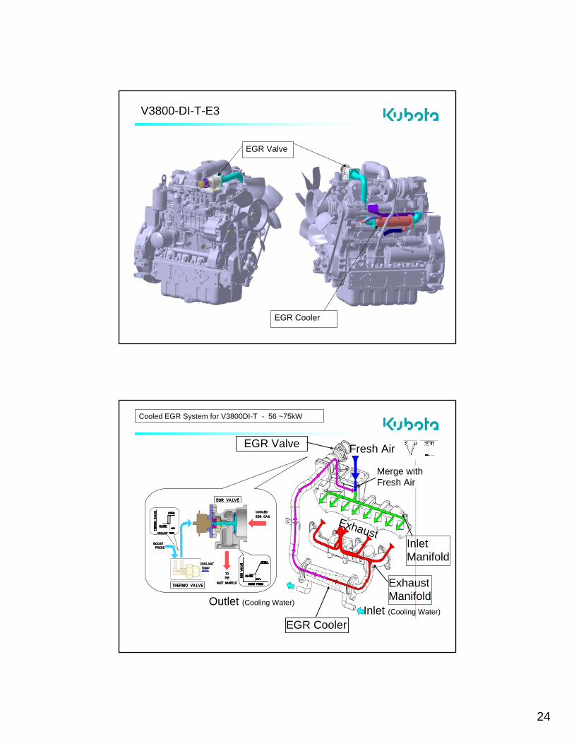
EGR Valve
EGR Cooler
V3800-DI-T-E3
Cooled EGR System for V3800DI-T - 56 ~75kW
Inlet Manifold
EGR Valve
Inlet (Cooling Water)
Fresh Air
Exhaust
Merge with Fresh Air
THER
MO
VALV
E OPEN
CLOSE
COOLANT TEMP
65℃
EGR VALVE
THERMO VALVE
COOLANTTEMP
BOOSTPRESS
EGR
VALV
E OPEN
CLOSE
BOOST PRESS
15kPa
TOTHE
INLET MANIFOLD
COOLEDEGR GAS
THER
MO
VALV
E OPEN
CLOSE
COOLANT TEMP
65℃THER
MO
VALV
E OPEN
CLOSE
COOLANT TEMP
65℃
EGR VALVE
THERMO VALVE
COOLANTTEMP
BOOSTPRESS
EGR
VALV
E OPEN
CLOSE
BOOST PRESS
15kPa
EGR
VALV
E OPEN
CLOSE
BOOST PRESS
15kPa
EGR
VALV
E OPEN
CLOSE
BOOST PRESS
15kPa
TOTHE
INLET MANIFOLD
COOLEDEGR GAS
Outlet (Cooling Water)
EGR Cooler
Exhaust Manifold
25
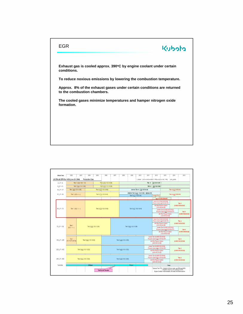
EGR
Exhaust gas is cooled approx. 390oC by engine coolant under certain conditions.
To reduce noxious emissions by lowering the combustion temperature.
Approx. 8% of the exhaust gases under certain conditions are returned to the combustion chambers.
The cooled gases minimize temperatures and hamper nitrogen oxideformation.
26
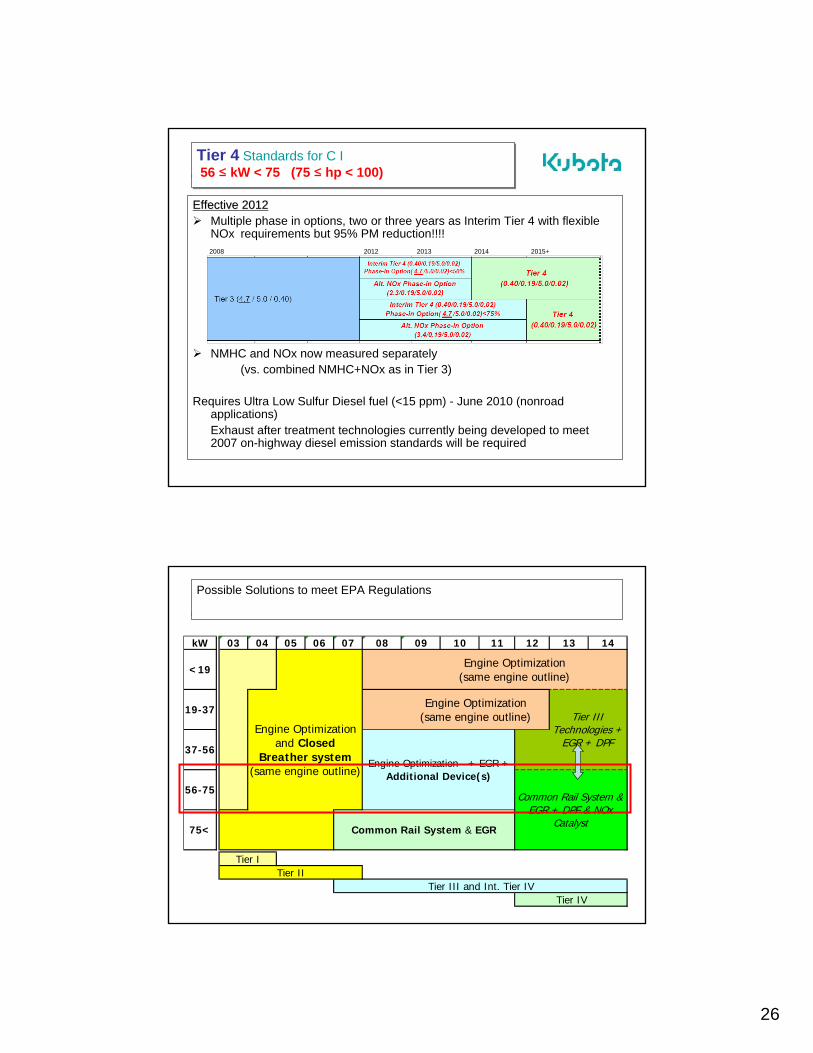
Tier 4 Standards for C I56 ≤ kW < 75 (75 ≤ hp < 100)
Tier 4 Standards for C I56 ≤ kW < 75 (75 ≤ hp < 100)
Effective 2012Effective 2012Multiple phase in options, two or three years as Interim Tier 4 with flexible NOx requirements but 95% PM reduction!!!!2008 2012 2013 2014 2015+
NMHC and NOx now measured separately(vs. combined NMHC+NOx as in Tier 3)
Requires Ultra Low Sulfur Diesel fuel (<15 ppm) - June 2010 (nonroad applications)Exhaust after treatment technologies currently being developed to meet 2007 on-highway diesel emission standards will be required
Possible Solutions to meet EPA Regulations
kW 03 04 05 06 07 08 09 10 11 12 13 14
Tier IV
Engine Optimization (same engine outline)
Engine Optimization (same engine outline)
Tier III and Int. Tier IV
Tier III Technologies +
EGR + DPF
Common Rail System & EGR + DPF & NOx
CatalystCommon Rail System & EGR
Engine Optimization + EGR + Additional Device(s)
75<
Tier ITier II
Engine Optimization and Closed
Breather system (same engine outline)
<19
19-37
37-56
56-75

27
Summary – CI Emissions Reductions Tier 2 to Tier 4:
<19kW (25hp) NOx, CO same, PM drops 50% 19 ~ 37kW (25~50hp) NOx drops 37%, PM drops 95%37 ~ 56kW (50~75hp) NOx drops 37%, PM drops 93%56 ~ 75kW (75~100hp) NOx drops 95%, PM drops 95%
Significant reductions requiring much greater control of combustion (Engine optimization + EGR) and addition of exhaust after treatment (PM filters).
Regulations Address New Engines
Electric Controlled Engines: 2007- ECU, Common rail fuel injection, EGRPM Control Aftertreatment: 2012/13- PM filter (DPF) over 19kW engines NOx Control Aftertreatment: 2014/15- NOx Catalyst over 57kW enginesFuel Diversity:- Low sulfur diesel (LSD) 500 ppm 2007- Ultra low sulfur diesel (USLD) 15 ppm 2010- Biodiesel B5 Immediate

28
V38DICR-TIE3-S

29
V38DICRV38DICR--TIE3TIE3--SSHigh Pressure Common Rail SystemHigh Pressure Common Rail System
ECU
Sensors
Fuel Injector
Rail (Max:160 MPa,23206 PSI) Supply Pump
1
23
V38DICRV38DICR--TIE3TIE3--SSNew and Modified Parts Location (1)New and Modified Parts Location (1)
Crankshaft Position Sensor
Pulsar Gear Intake Air Temperature Sensor
Intake Air Pressure Sensor
4
7
5
6
Rail
Supply Pump
3
2

30
V38DICRV38DICR--TIE3TIE3--SSNew and Modified Parts Location (2)New and Modified Parts Location (2)
Camshaft Position Sensor
EGR Valve10
9
Head Cover11
V38DICRV38DICR--TIE3TIE3--SSNew and Modified Parts Location (3)New and Modified Parts Location (3)
EGR Cooler
Coolant Temperature Sensor Cylinder Head8 18
14

31
V38DICRV38DICR--TIE3TIE3--SSHigh Pressure Common Rail SystemHigh Pressure Common Rail System
Fuel Injector
V38DICRV38DICR--TIE3TIE3--SSFUEL INJECTORFUEL INJECTOR EXTERNAL EXTERNAL VIEW (1)VIEW (1)
QR Codes
ID Codes
Connector

32
V38DICRV38DICR--TIE3TIE3--SSFUEL INJECTORFUEL INJECTOR
V38DICRV38DICR--TIE3TIE3--S EGR VALVES EGR VALVE
EGR Valve
10mm
Motor & Lift SensorConnector
33
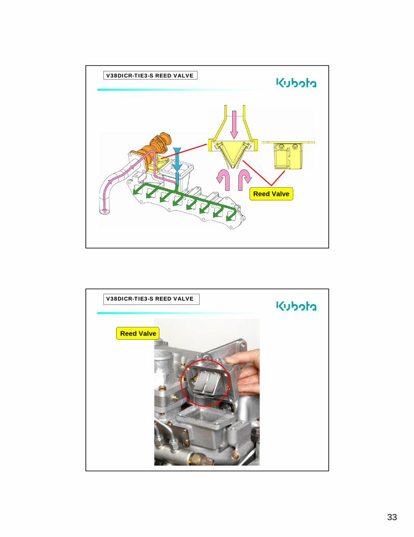
V38DICRV38DICR--TIE3TIE3--S REED VALVES REED VALVE
Reed Valve
V38DICRV38DICR--TIE3TIE3--S REED VALVES REED VALVE
Reed Valve

34
Typical CRS ECU CONTROLTypical CRS ECU CONTROL SYSTEM DIAGRAMSYSTEM DIAGRAM
Typical CRS ECU Typical CRS ECU CONTROLCONTROL SYSTEMSYSTEM
35
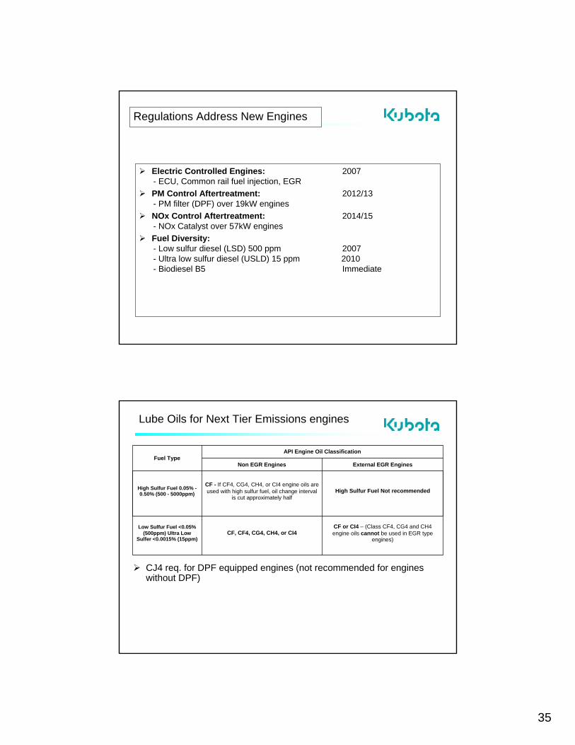
Regulations Address New Engines
Electric Controlled Engines: 2007- ECU, Common rail fuel injection, EGRPM Control Aftertreatment: 2012/13- PM filter (DPF) over 19kW engines NOx Control Aftertreatment: 2014/15- NOx Catalyst over 57kW enginesFuel Diversity:- Low sulfur diesel (LSD) 500 ppm 2007- Ultra low sulfur diesel (USLD) 15 ppm 2010- Biodiesel B5 Immediate
Lube Oils for Next Tier Emissions engines
CJ4 req. for DPF equipped engines (not recommended for engines without DPF)
CF or CI4 – (Class CF4, CG4 and CH4 engine oils cannot be used in EGR type
engines)CF, CF4, CG4, CH4, or CI4
Low Sulfur Fuel <0.05% (500ppm) Ultra Low
Sulfer <0.0015% (15ppm)
High Sulfur Fuel Not recommendedCF - If CF4, CG4, CH4, or CI4 engine oils are used with high sulfur fuel, oil change interval
is cut approximately half
High Sulfur Fuel 0.05% -0.50% (500 - 5000ppm)
External EGR EnginesNon EGR Engines
API Engine Oil ClassificationFuel Type

36
Nonroad Diesel FuelNonroad Diesel Fuel
ULSDULSDBenefits:
Allows use of Sulfur-Sensitive Control Technologies such as DOC and DPF’s etc.
Challenges:Lower lubricityPlunger / in-line injection pumps, much less susceptible than Rotary typesFuel economy may be lowered by 2-3% (less BTU content)
2010(CURRENT IN CALIFORNIA)
Jun-0615 (0.0015% wt)
Jun-071993500 (0.05% wt)
CURRENT<19933000
OFF ROADON ROADSulfur
Content (ppm)
Kubota "E 3" diesel engines less than 56kW (75hp) utilize EPA Tier 4 and IntermTier 4 standards Low sulfur or Ultra low sulfur fuel is mandatory for these engines when operated in US EPA regulated areas
Biodiesel
Renewable Energy InitiativesPolitical desire to utilize, off-shore fuel dependency etc.
Base = vegetable oil (soybean oil) in N. America
No current ASTM standard anything < B100 (B100 = 100% Bio Diesel, B50 = a blend of 50% Bio Diesel / 50% traditional diesel)B100 - ASTM standard D 6751, Standard Spec (B100) fuel, adopted 2002. Blends of BIO-DIESL ASTM D975
Wide variation in fuel characteristics geographically
37
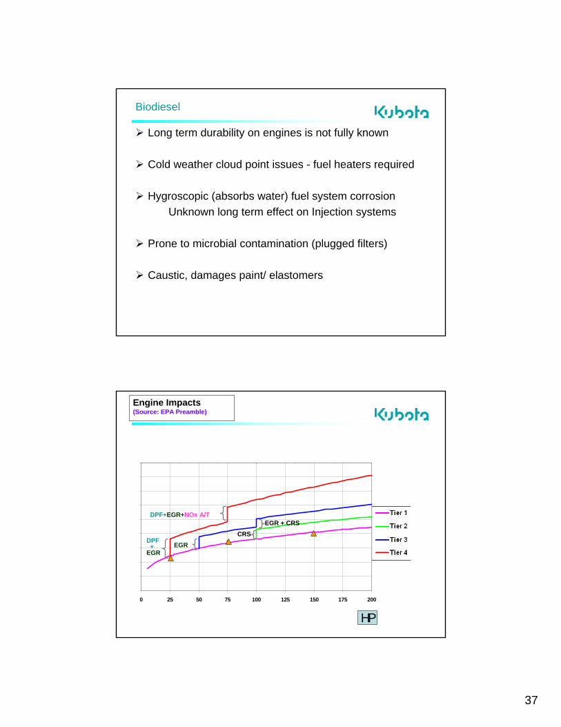
Biodiesel
Long term durability on engines is not fully known
Cold weather cloud point issues - fuel heaters required
Hygroscopic (absorbs water) fuel system corrosionUnknown long term effect on Injection systems
Prone to microbial contamination (plugged filters)
Caustic, damages paint/ elastomers
Engine Impacts(Source: EPA Preamble)
0 25 50 75 100 125 150 175 200
0 25 50 75 100 125 150
Kilowatts
Tier 1
Tier 2
Tier 3
Tier 4
DPF+
EGR
DPF+EGR+NOx A/T
EGRCRS
EGR + CRS
HP

38
Minimum Fuel Consumpt ion
150
160
170
180
190
200
210
220
1950 1960 1970 1980 1990 2000 2010Year of Development
Min
imum
Fue
l Con
sum
ptio
n (g
/PSh
IDI
DI
CHANGE OF KUBOTA DIESEL ENGINES POWER DENSITY
75
Power Output / Weight
0
0.05
0.1
0.15
0.2
0.25
0.3
0.35
0.4
0.45
1950 1960 1970 1980 1990 2000 2010Year of Development
Pow
er O
utpu
t/ W
eigh
t(PS
/kg
CHANGE OF KUBOTA DIESEL ENGINES POWER DENSITY
76

39
Pow er O u t pu t / C onst it u t ion
0
0 .05
0 .1
0 .15
0 .2
0 .25
0 .3
0 .35
1950 1960 1970 1980 1990 2000 201 0Year o f D eve lo pme n t
Pow
er O
utpu
t / C
onst
itutio
n(
PS/l)
CHANGE OF KUBOTA DIESEL ENGINES POWER DENSITY
77
Crankcase
D905D902

40
D905D722 D902
Pistons
V3307-DI-T

41
505.2 538.4
504.8
672.
8
760.
0
660.
6
671.2713.4
672.6
Comparison of L×W×H
V24030.228 m3
(100%)
V3307-DI0.224 m3
(98%)
V3300,V3800V3300,V38000.292 m3
(128%)
(2.434 L)
(3.331 L)
(3.318 L) (3.769 L)

MDEC 2007 Workshop
S2 - 1
Diesel Engine Maintenance
Presented by Walter StefflerKubota Canada Ltd.
MDEC ConferenceDiesel Workshop
October 2, 2007
Types of Maintenance Break in – During the break in period, engine oil and filter should be changed after the first 50 hours of service. The engine should be warmed up for a few minutes, before heavy use.
Daily – Checks should be performed ie oil, fuel, air ( only if restrictor is present), anti- freeze. Gauges and controls
Scheduled – As per engine manufacturer’s schedule.

MDEC 2007 Workshop
S2 - 2
Maintenance Practices
Questions I should be asking of my maintenance program.
Do I have one ? Or Repair as Required.
If I do , Are there accurate records ?
How are my supplies stored ?
How are my Actual vs Manufactures maintenance schedules ?
Daily Checks
Oil or coolant leaks
Engine oil level and contamination
Amount of fuel- fuel level.
Amount of coolant – coolant level
Check that the radiator is free of obstruction
Damaged parts, loose bolts or fasteners
Visual walk around.

MDEC 2007 Workshop
S2 - 3
In operating position.
Are the Gauges, Meters and Pilot lamps functioning properly?
Proper function of the glow lamps and timers.
When starting the engine, what is the colour of the exhaust ? Excessive smoke?
Is there unusual engine noise ?
Fluid Checks
Lubricating Oil Check Oil Level Too high is as bad as
too low! Look for leaks, check
date/hours of last service
Fuel Check Quantity Check for
contamination Drain water from
water separator if equipped

MDEC 2007 Workshop
S2 - 4
Fluid Checks
Antifreeze/Coolant50/50 mix is required. Higher concentrations can cause engine damage.If low, top off with:
50/50Antifreeze if low because of leakWater if low because of evaporation
Check both the radiator and recovery bottle !
With some types of leaks, the bottle could be full and the radiator empty.
OILS

MDEC 2007 Workshop
S2 - 5
Selecting oil
Diesel
What does the “C” represent?
Gas
What does the “S” represent?
Selecting Oil
What does the “E” in “CE” represent?What is “CF-4”?

MDEC 2007 Workshop
S2 - 6
Selecting Oil
As engine oils become more dedicated to specific applications, PLEASE be very careful
What happens if I do not have a regular maintenance program ?

MDEC 2007 Workshop
S2 - 7
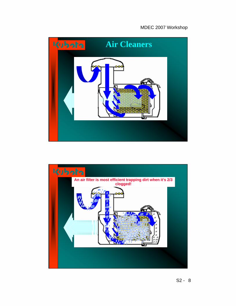
Air Cleaners
Air Cleaner System
Two of the most common air cleaner servicing problems.
1 ) Over servicing : Filter are the least efficient when new. Filter elements increase in efficiency as dust builds up on the media.
2) Improper servicing : your engine is highly vulnerable to abrasive dust contaminants during the servicing process when the filter is removed from the housing. A leading cause of engine damage is due to careless servicing procedures.
Note : It takes about 1 table spoon of dirt to damage a Diesel engine.
MDEC 2007 Workshop
S2 - 8
Air Cleaners
An air filter is most efficient trapping dirt when it’s 2/3 clogged!
An air filter is most efficient trapping dirt when it’s 2/3 clogged!
MDEC 2007 Workshop
S2 - 9
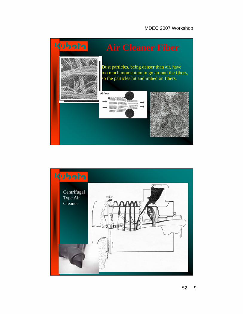
Air Cleaner Fiber
Dust particles, being denser than air, have too much momentum to go around the fibers, so the particles hit and imbed on fibers.
CentrifugalType AirCleaner

MDEC 2007 Workshop
S2 - 10
Air Cleaners
Check the dust cup or evacuator daily ( if equipped)
Don’t replace the air filter early!
Replacing the filter at ¼ the required interval means you’re 300% more likely to cause engine damage
Air Cleaner System
Centrifugal types
Baffle plate
Dust evacuatorWhat makes it discharge particles?
MDEC 2007 Workshop
S2 - 11
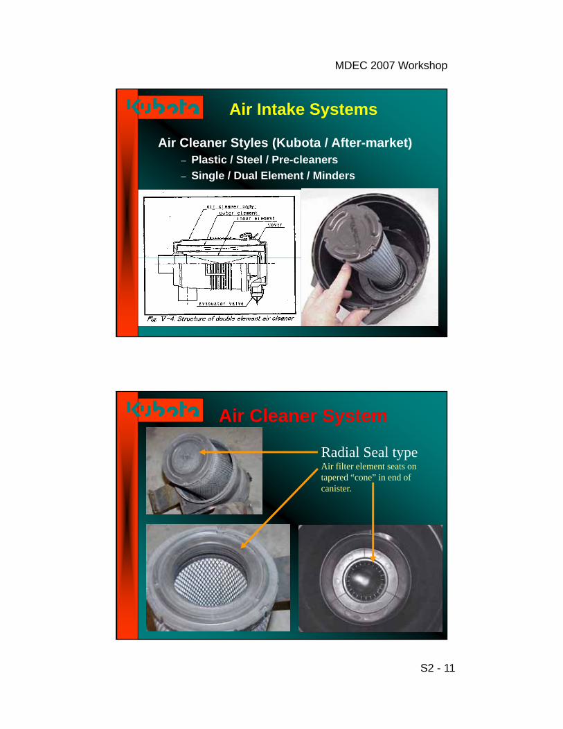
Air Intake Systems
Air Cleaner Styles (Kubota / After-market)– Plastic / Steel / Pre-cleaners– Single / Dual Element / Minders
Air Cleaner System
Radial Seal typeAir filter element seats on tapered “cone” in end of canister.

MDEC 2007 Workshop
S2 - 12
Air Cleaner System
Check for good seating of sealing washer
Check for good seating of air cleaner element against base of air cleaner housing.
Conventional type
Air Cleaner System
Square type seal
NOT ALL SEALS ARE GOOD!This type of seal cost big $$$$$
Lip type seal, as air intake restriction increases, lip seal tightens

MDEC 2007 Workshop
S2 - 13
Air Cleaner System
Inspection of element
Any problems?
Air Cleaner System
Poor air inlet system security, abrasive dust can enter inlet and engine failure results.

MDEC 2007 Workshop
S2 - 14
Air Intake SystemsAir Cleaner Location / Mounting
Intake Air Temperature
Fuel SystemDiesel
MDEC 2007 Workshop
S2 - 15
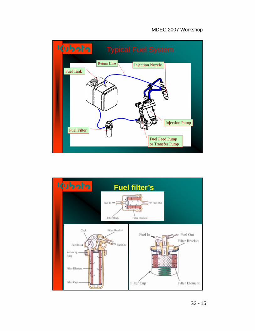
Typical Fuel System
Fuel Tank
Return Line Injection Nozzle
Injection Pump
Fuel Feed Pump or Transfer Pump
Fuel Filter
Fuel filter’s
MDEC 2007 Workshop
S2 - 16
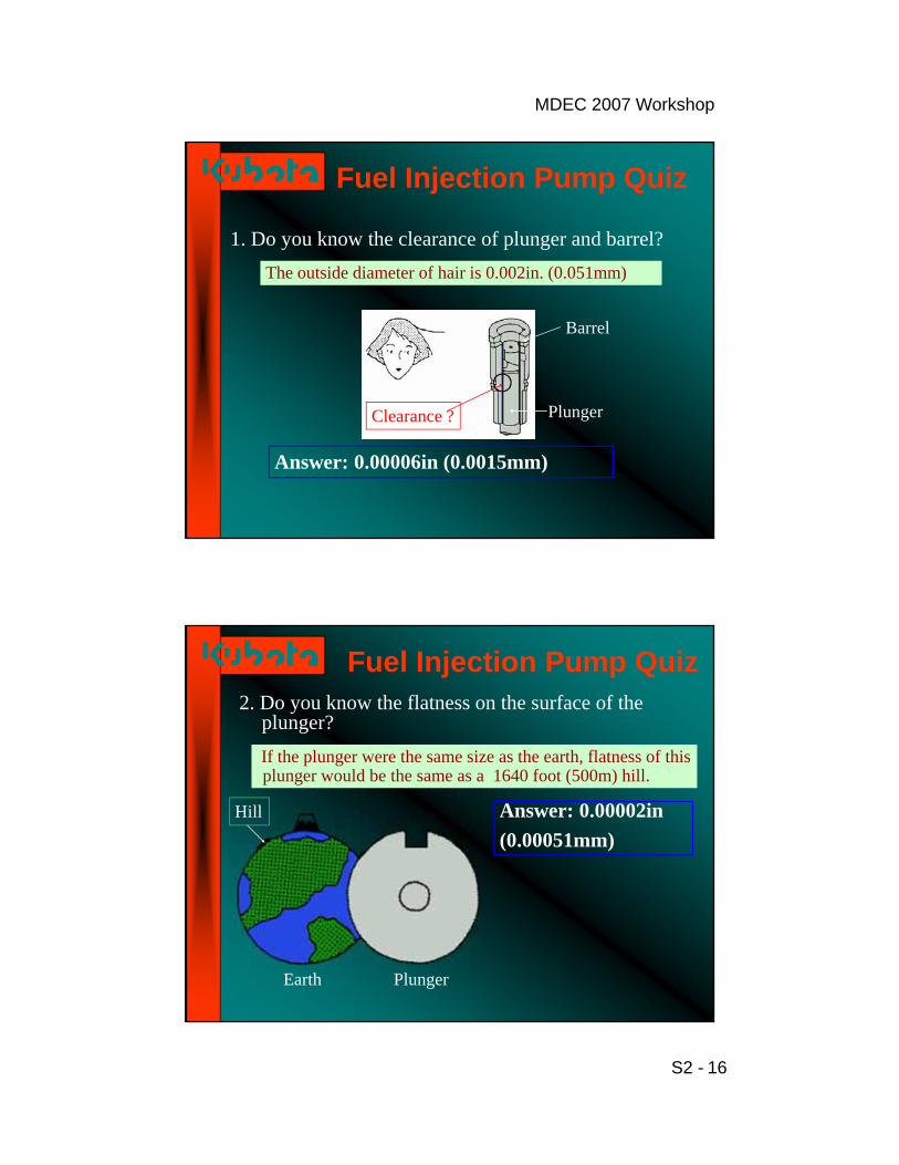
Fuel Injection Pump Quiz
1. Do you know the clearance of plunger and barrel?The outside diameter of hair is 0.002in. (0.051mm)
Barrel
PlungerClearance ?
Answer: 0.00006in (0.0015mm)
Fuel Injection Pump Quiz2. Do you know the flatness on the surface of the
plunger?If the plunger were the same size as the earth, flatness of this plunger would be the same as a 1640 foot (500m) hill.
Answer: 0.00002in(0.00051mm)
Hill
Earth Plunger
MDEC 2007 Workshop
S2 - 17
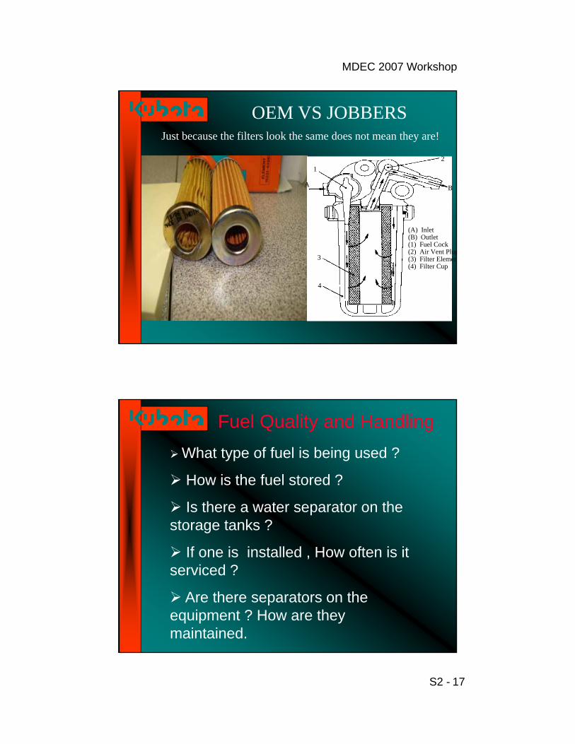
OEM VS JOBBERSJust because the filters look the same does not mean they are!
1
A
3
4
2
B
(A) Inlet (B) Outlet (1) Fuel Cock (2) Air Vent Plug(3) Filter Elemen(4) Filter Cup
Fuel Quality and Handling
What type of fuel is being used ?
How is the fuel stored ?
Is there a water separator on the storage tanks ?
If one is installed , How often is it serviced ?
Are there separators on the equipment ? How are they maintained.

MDEC 2007 Workshop
S2 - 18
Fuel
Fuel stored in outside tanks are susceptible to condensation build up. Micro organisms can build up to plug filters destroy the injection pumps and nozzles.
Bio diesels Biodiesel can be blended with petroleum-based diesel. Most manufactures allow up to 20% blended fuels.
Biodiesels are affected more by cold temperatures so heaters may have to be installed.
MDEC 2007 Workshop
S2 - 19
Cooling System
Cooling System
Things I should check.
Fan belt- Check for cracks, tears, pieces missing and tension.
Anti freeze – Correct level, correct mixture (50/50)
Radiator clean and free from obstruction.
Is my coolant mixture pre-mixed or not?

MDEC 2007 Workshop
S2 - 20
Boiling Points of Coolant vs. Water
Maximum operating temperature - below thermostat = 110C (230F) Normal operating temperature = 72 to 98C (161 to 208F)
Boiling point of coolant.
Rad cap pressure % of water / antifreeze Boiling point Celsius Fahrenheit
0 psi (0 kg/cm2) 100 % water 100 21250 / 50 108 226
13 psi (0.9 kg/cm2) 100 % water 118 24450 / 50 126 259
Maximum antifreeze concentration = 60%
Silicate GelationCaused by overdosing high silicate antifreeze and
supplemental coolant additives (SCA’s)
plugging
Purpose of Silicate: Aluminum protection
MDEC 2007 Workshop
S2 - 21
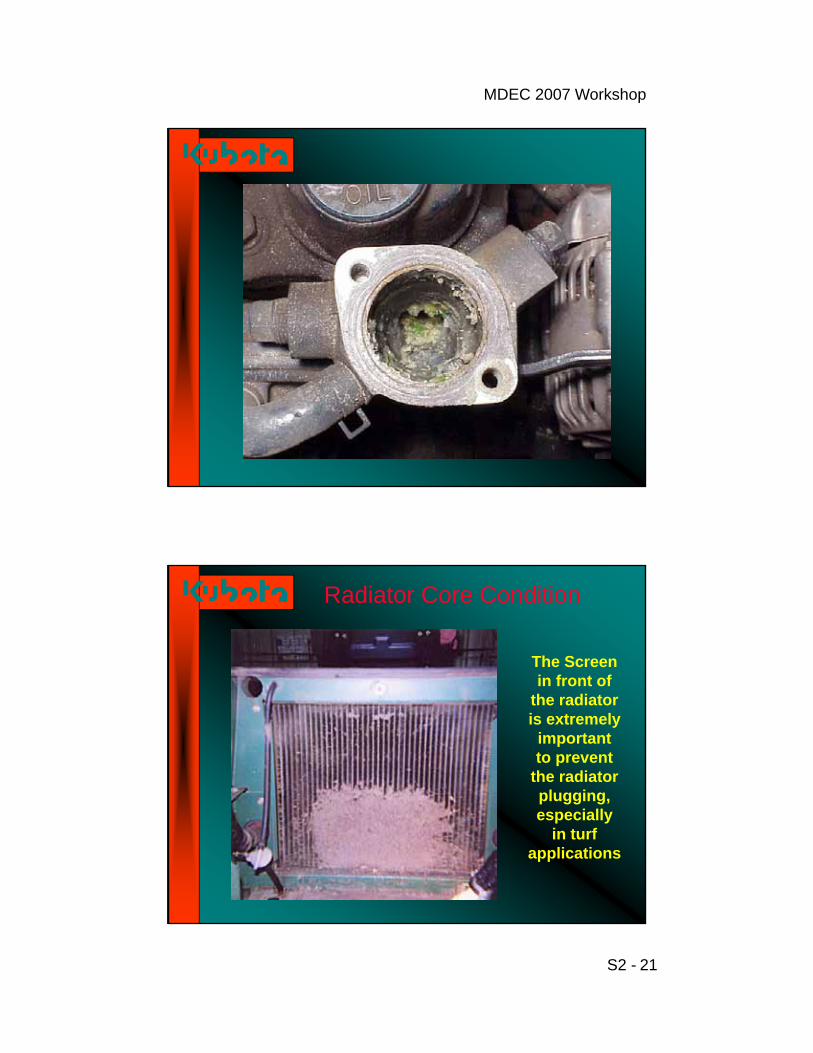
Radiator Core Condition
The Screen in front of
the radiator is extremely
important to prevent
the radiator plugging, especially
in turf applications

MDEC 2007 Workshop
S2 - 22
Check for restriction BETWEEN radiator and oil coolers
Valve Adjustment
Intake Valve “Bridge
To Adjust Bridge:
•Loosen Lock Nut.
•Push down on bridge gently
•Turn Adjusting Screw until it just contacts valve stem
•Tighten Lock Nut
•Adjust valves to proper specification

MDEC 2007 Workshop
S2 - 23
CONCLUSION
Factors that affect my engines life.
Application
Load factors
Oil change interval
Air cleaner service
Type of fuels used
Most important factor is “Preventive Maintenance”. NOT just repair.
Follow manufactures recommendation on maintenance intervals.
Thank You.

MDEC 2007 Workshop
S3 - 1
WORKSHOPDiesel Particulate Filter
FundamentalsSelection & Sizing
Retrofit & OperationMaintenance
MDECMining Diesel Emissions Council
October 1st – 5th, 2007
Presented By Glen PrisciakDCL International Inc.
WORKSHOPDiesel Particulate FilterFundamentals
Overview - Fundamentals
• What is a DPF and how does it work?
• Substrates and substrate properties
• Details of trapping mechanisms and backpressure derivatives
• DPF systems and regeneration strategies• Active off-board• Active on-board• Passive
MDEC 2007 Workshop
S3 - 2
WORKSHOPDiesel Particulate FilterFundamentals
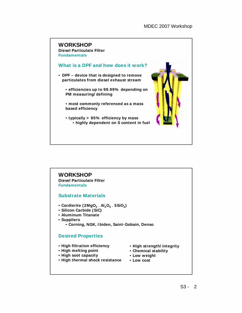
What is a DPF and how does it work?
• DPF – device that is designed to remove particulates from diesel exhaust stream
• efficiencies up to 99.99% depending on PM measuring/defining
• most commonly referenced as a mass based efficiency
• typically > 85% efficiency by mass• highly dependent on S content in fuel
WORKSHOPDiesel Particulate FilterFundamentals
Substrate Materials
• Cordierite (2MgO2 Al2O5 5SiO2)• Silicon Carbide (SiC)• Aluminum Titanate• Suppliers
• Corning, NGK, Ibiden, Saint-Gobain, Denso
Desired Properties
• High filtration efficiency• High melting point• High soot capacity• High thermal shock resistance
• High strength/integrity• Chemical stability• Low weight• Low cost

MDEC 2007 Workshop
S3 - 3
WORKSHOPDiesel Particulate FilterFundamentals
Cordierite
• Low thermal expansion coefficient• Good mechanical strength• Lower) melting point (~1450C)• Low heat capacity
SiC• High thermal expansion coefficient• High melting point (~2700C)• High heat capacity
Courtesy: www. ngk.co.jp
WORKSHOPDiesel Particulate FilterFundamentals
Trapping Mechanisms
• Inertial Impaction
• Interception
• Diffusional Deposition(Brownian Diffusion)

MDEC 2007 Workshop
S3 - 4
WORKSHOPDiesel Particulate FilterFundamentals
Particle Size in Perspective
• Typical DPF pore size is ~10-20 m• Typical diesel exhaust PM size distribution is:
Courtesy: www.dieselnet.com
WORKSHOPDiesel Particulate FilterFundamentals
To put it in perspective
Courtesy: www.sportschrome.com

MDEC 2007 Workshop
S3 - 5
WORKSHOPDiesel Particulate FilterFundamentals
Depth Bed vs. Cake Filtration
Courtesy: www.dieselnet.comCourtesy: Konstandopoulos, A., Masoudi, M.
WORKSHOPDiesel Particulate FilterFundamentals
Computational Model
Inverse Computational Model
Courtesy: Konstandopoulos, A., Masoudi, M.
MDEC 2007 Workshop
S3 - 6
WORKSHOPDiesel Particulate FilterFundamentals
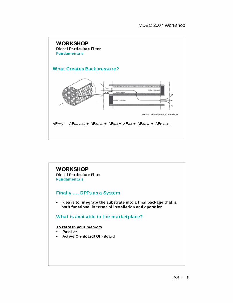
What Creates Backpressure?
PTOTAL = PContraction + PChannel + PSoot + PWall + PChannel + PExpansion
Courtesy: Konstandopoulos, A., Masoudi, M.
WORKSHOPDiesel Particulate FilterFundamentals
Finally …. DPFs as a System
• Idea is to integrate the substrate into a final package that is both functional in terms of installation and operation
What is available in the marketplace?
To refresh your memory• Passive• Active On-Board/Off-Board

MDEC 2007 Workshop
S3 - 7
What is available in the market? • Passive Regeneration
• Soot regeneration temperature is 550-600 deg-C but can be reduced significantly when filter block is coated with oxidation catalyst• Soot regeneration rate is enhanced by adding special ingredient to wash-coat composition - promoters• Two oxidation mechanisms;
• NO2 Oxidation• High loading DOC is upstream the DPF to produce NO2 from the ~90% engine out NO• NO2 oxidizes soot at low temperatures: 270-320 deg-C• NO2 consumption depends on soot load and that makes tailpipe NO2emissions uncontrolled
• O2 Oxidation • Two catalyst families;
• Precious Metal Catalyst: reduce BPT to 280-350 deg-C• Base Metal Catalyst: reduce BPT to 375-420 deg-C
• Fuel Born Catalyst (Additives)
WORKSHOPDiesel Particulate FilterFundamentals
WORKSHOPDiesel Particulate FilterFundamentals
NO2
Catalyst(Pt) Filter (Bare)
NO, O2
PM
NO2
PM
NO, NO2
Unpredictable in NO2 output
Generally high
Higher in CCRT
Filter (Pt)NO, O2
PM
NO, NO2
Filter (V2O5)NO, O2
PM
NO
Courtesy www.ect.jmcatalysts.com

MDEC 2007 Workshop
S3 - 8
What is available in the market?• Active Regeneration
• On-board automated active (passive forced regeneration)• Diesel burner is triggered by DPF differential pressure at target engine modes• Diesel fuel post injection (manifold) to produce exothermic condition over heavy loaded DOC to force the DPF regeneration
• Off-board manual active – Shift End• Diesel Burner is triggered manually at the end of each shift• Electrical Heater is triggered manually at the end of each shift
WORKSHOPDiesel Particulate FilterFundamentals
WORKSHOPDiesel Particulate FilterFundamentals
Active On-Board
Active Off-Board Courtesy: Konstandopoulos, A., Masoudi, M.
MDEC 2007 Workshop
S3 - 9
WORKSHOPDiesel Particulate FilterFundamentals
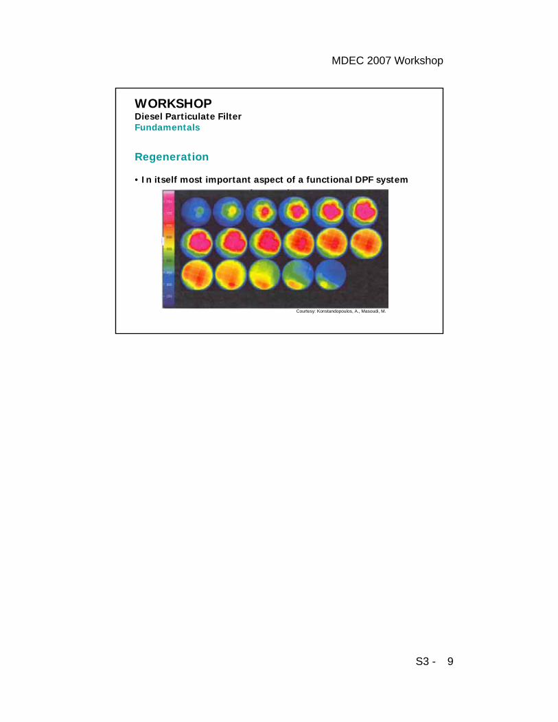
Regeneration
• In itself most important aspect of a functional DPF system
Courtesy: Konstandopoulos, A., Masoudi, M.

MDEC 2007 Workshop
S4 - 1
WORKSHOPDiesel Particulate Filter
FundamentalsSelection & Sizing
Retrofit & OperationMaintenance
MDECMining Diesel Emissions Council
October 1st – 5th, 2007
Presented By Ted N TadrousEngine Control Systems Limited
So you’ve determined you need a DPF!
To qualify your application for DPF retrofit – you need to determine;
• Duty cycle• Exhaust temperature profile• Shift pattern & duration
• Certified engine out PM level
• Available space envelope
• Sulfur level in diesel fuel
• Emission contribution of application as part of a fleet/shift
• Operation sensitivity to NO2 formation and/or ambient levels
• NOx / PM Ration [>20 is desired]
WORKSHOPDiesel Particulate FilterSelection & Sizing

MDEC 2007 Workshop
S4 - 2
• Selection is based on duty cycle & operation logistics• Shift duration & pattern• Exhaust temperature traces for at least 3 days to determine
repeated duty cycle.• Analysis of exhaust temperature trace & histogram• Duration of idling & low load condition
WORKSHOPDiesel Particulate FilterSelection & Sizing
Bare DPF Base Metal Precious Metal Active>550oC 380-420oC 280-320oC NA
WORKSHOPDiesel Particulate FilterSelection & Sizing
Courtesy of ECS
24.49%
56.21%

MDEC 2007 Workshop
S4 - 3
WORKSHOPDiesel Particulate FilterSelection & Sizing
Sizing is based on engine parameters & PM emission level• PDF capacity to accommodate max exhaust flow causing
minimum restriction leaving room for soot accumulation • More soot accumulation >>>> Larger DPF volume• SiC has slightly more soot capacity than Cordierite
Courtesy of ECS
SiC-DPFSafety Area
Cord.-DPF Safety Area
×
×
×
××
××
×
×S C Non crackSiC Cracked
i
5
10
15
20
25
30
35
0.2 0.4 0.6 0.8 1 . 0 1.2 1.4 1.6 1.8 2.0 2.2 2.40
Ai r veloc i ty (m/sec)
k
×
×
×
×Crack
×Co rd . Non cracCo rd . Cracked
or Me l ted
SiC limit is 8 g/lit soot loading while Cordierite has 6 g/lit capacity
PM W
eigh
t (g/
lit)
WORKSHOPDiesel Particulate FilterSelection & Sizing
Courtesy of Ibiden

MDEC 2007 Workshop
S4 - 4
WORKSHOPDiesel Particulate FilterSelection & Sizing
Courtesy of ECS
DPF System Supplier is Responsible for Sizing
• Using engine data sheet, obtain;– Exhaust flow rate @ rated power,
– Maximum allowable backpressure– Specific PM emission
• Using DPF System Sizing Guidelines / Tool;– Enter exhaust flow @ rated power, and– PM specific emission [g/bhp-hr]– Select the model corresponding to max allowable
BP
exh
atmvol
P
P
KAmbTemp
KTempExh][
][.
2
RPM
1728
[CID]EngineDisp]wRate[ACFMExhaustFlo η

MDEC 2007 Workshop
S4 - 5
WORKSHOPDiesel Particulate FilterSelection & Sizing
Snapshot of a typical engine data sheet
WORKSHOPDiesel Particulate FilterSelection & Sizing
Courtesy of ECS

MDEC 2007 Workshop
S4 - 6
WORKSHOPDiesel Particulate FilterSelection & Sizing
Courtesy of ECS

MDEC 2007 Workshop
S5 - 1
WORKSHOPDiesel Particulate Filter
FundamentalsSelection & Sizing
Retrofit & OperationMaintenance
MDECMining Diesel Emissions Council
October 1st – 5th, 2007
Presented By Don MalgastEngine Control Systems Limited
• Application specific requirements such as surface temperature, …etc.
• Vertical or horizontal orientation may be critical from a DPF system design or application vibration view point
• Following the manufacturer installation guidelines is critical
• Opacity baseline for tuned engine prior retrofit is important
• DPF system must include performance diagnostic kit including alarms
• Operator Training
WORKSHOPDiesel Particulate FilterRetrofit & Operation of your DPF System:

MDEC 2007 Workshop
S5 - 2
WORKSHOPDiesel Particulate FilterRetrofit & Operation of your DPF System:
Vertical Mount (Stack)•Locate best position for the DPF assembly.This usually is in the location of the existingsilencer/muffler.
•Remove the existing silencer/muffler.
•Support the DPF assembly at the filtercenter body using mounting brackets.
• Mount support brackets securely to frameor cab stanchion.
• Install exhaust flex pipe between inlet ofDPF and exhaust pipe 24” from engine, toabsorb vibration and cab movement.
•Install a Backpressure Monitor Kit as permanufacturer recommendation.
WORKSHOPDiesel Particulate FilterRetrofit & Operation of your DPF System:
Under Chassis Mounting•Locate the best position for the DPFassembly. This is in the location of theexisting silencer/muffler.
•Remove the existing silencer/muffler.
•Support the DPF assembly at the filtercenter body using mounting brackets.
•Mount support brackets securely tochassis.
•Install exhaust flex pipe between inletof DPF and exhaust pipe 24” fromengine to absorb vibration.
•Install a Backpressure Monitor Kit as
recommended by manufacturer.

MDEC 2007 Workshop
S5 - 3
WORKSHOPDiesel Particulate FilterRetrofit & Operation of your DPF System:
Horizontal Mounting•Locate the best position for the DPFassembly. This is in the location of theexisting silencer/muffler.
•Remove the existing silencer/muffler.
•Install DPF in place of the originalmuffler.
•Support the DPF assembly at the filtercenter body using mounting brackets.
•Mount support brackets securely todeck or fender
•Install exhaust flex between inlet of
DPF and exhaust pipe 24” from engineto absorb vibration.
•Install a Backpressure Monitor Kit asrecommended by manufacturer.
WORKSHOPDiesel Particulate FilterRetrofit & Operation of your DPF System:
Vertical Dual Mounting•Locate the best position for theDPF assembly. This is in thelocation of the existingsilencer/muffler.
•Remove the existingsilencer/muffler.
• Install DPF in place of the originalmuffler
• Mount support brackets securelyto deck
• Install exhaust flex between inlet
of DPF and exhaust pipe 24” fromengine to absorb vibration.
•Install the Backpressure MonitorKit as recommended bymanufacturer.

MDEC 2007 Workshop
S5 - 4
WORKSHOPDiesel Particulate FilterRetrofit & Operation of your DPF System:
Performance monitoring is essential to protect both the engine and DPF;
• Continuous monitoring for back pressure and alarming for excessive levels will help indicate cleaning requirement
• Continuous monitoring of duty cycle help explain DPF performance and prevent premature service and down time
WORKSHOPDiesel Particulate FilterRetrofit & Operation of your DPF System:

MDEC 2007 Workshop
S6 - 1
WORKSHOPDiesel Particulate Filter
FundamentalsSelection & Sizing
Retrofit & OperationMaintenance
MDECMining Diesel Emissions Council
October 2nd , 2007
Presented By John StekarCatalytic Exhaust Products Limited
Regardless of the regeneration strategy,DPF restriction will increase over time dueto the accumulation of the ash inside thefilter and compaction of un-combusted soot.
Diesel Particulate Filters (DPF) and DieselOxidation Catalysts (DOC) collect dieselparticulate matter and inorganic basedexhaust constituents. Inorganic basedexhaust constituents are typically known asash. Ash does not oxidize into a gaseousstate as does diesel particulate matter. Ashforms oxides and sulphates which arestored within the DPF.
An essential component to effective use andsafeguard the filter is to remove the ashoccasionally to avoid sintering with DPFmaterial under exothermic regenerationconditions.
WORKSHOPDiesel Particulate FilterMaintenance of your DPF System:

MDEC 2007 Workshop
S6 - 2
Sources of Inorganic based Ash:• diesel engine exhaust system corrosion (iron)
• diesel engine metals and engine component wear (copper, tin, aluminum, silicon, chromium, nickel and iron)
• oxidized engine crankcase lubrication oil. (sulphur, calcium, zinc, magnesium and phosphorus)
• by-products of diesel fuel additives (cerium, platinum and iron).
WORKSHOPDiesel Particulate FilterMaintenance of your DPF System:

MDEC 2007 Workshop
S6 - 3
Effects of Ash• With engine usage inorganic based ash will gradually
accumulate within the Diesel Particulate Filter and Diesel Oxidation Catalysts.
• The pressure drop across the DPF/DOC will increase until engine exhaust gas flow restriction exceeds engine manufacturer exhaust gas backpressure restriction recommendations.
• Excessive engine exhaust gas backpressure restriction will result in gradual degradation of diesel engine performance, increased fuel consumption, increased oil consumption, high oil temperatures, high coolant temperatures, etc….
WORKSHOPDiesel Particulate FilterMaintenance of your DPF System:
Effects of Phosphorus in Ash
• Ash which contains higher levels of phosphorus may increase oxidation temperatures of DPM. This may result in incomplete and/or partial regeneration of DPF. This may also result in reduced pollutant oxidation (HC, CO, SOF) performance of DPF and DOC.
• Therefore diesel engines which consume higher amounts of engine lubrication oil could prove to be problematic. Higher engine exhaust gas temperatures will be required to achieve complete DPF regeneration.
• Excessive diesel engine oil consumption will result in deactivation and irrepairable damage to precious metal catalysts which are coated onto DPF and DOC or are found in platinum based diesel fuel additives.
WORKSHOPDiesel Particulate FilterMaintenance of your DPF System:

MDEC 2007 Workshop
S6 - 4
Minimizing Effects of Ash using Correct Crankcase OilsRecommended Diesel Engine Crankcase
Lubricating Oils:• 1) CJ-4 – contains less than 1.0% wt.
sulphated ash and less than 0.12% wt. phosphorus.
• 2) CI-4/CI-4+ – contains less than 1.5% wt. sulphated ash and less than 0.15%wt phosphorus.
WORKSHOPDiesel Particulate FilterMaintenance of your DPF System:
Minimizing Effects of Ash by Minimizing Engine Oil ConsumptionEnsure that the diesel engine is not consuming an
inordinate amount of crankcase lubrication oil by:
• 1) analyzing engine crankcase oil on a periodic basis to determine possible engine faults.
• 2) measuring and record volume of engine crankcase oil consumed over unit engine hours.
• 3) ensuring that engine oil volume consumed is within Engine Manufacturer tolerances.
• 4) taking necessary maintenance and repair actions to minimize engine oil consumption.
WORKSHOPDiesel Particulate FilterMaintenance of your DPF System:

MDEC 2007 Workshop
S6 - 5
DPF/DOC ash removal intervals:1) for newer engines (Tier 1-3) using CJ-4 engine crankcase oil and
ULSD which have minimal lubrication oil consumption rates, DPF ash removal procedures should be carried out every 1500-2000 engine operating hours or once every 12 months (whichever occurs first) or as required according to engine exhaust gas backpressure restriction levels.
2) For older engines (pre-Tier 1)using CJ-4 engine crankcase oil and ~500 ppm S which have higher lubrication oil consumption rates, DPF ash removal procedures should be carried out every 1000-1500 hours or once every 6 months (whichever occurs first) or as required according to engine exhaust gas backpressure restriction levels.
3) For diesel engines (pre and post Tier 1) using diesel fuel additives, ash collection rates will be higher and will vary according to additive dosage rates.
WORKSHOPDiesel Particulate FilterMaintenance of your DPF System:
Oil Consumption and Engine Duty Cycle/Age Variables
• light engine duty cycles may result in diesel engines which consume inordinate amount of engine crankcase oil.
• low engine speeds may result in diesel engines which consume inordinate amounts of engine crankcase oil.
• high hour diesel engines may consume inordinate amounts of engine crankcase oil.
WORKSHOPDiesel Particulate FilterMaintenance of your DPF System:
MDEC 2007 Workshop
S6 - 6
Manual DPF/DOC Ash Removal Field Procedure - Safety Equipment
• wear soil resistant clothing or disposable coveralls.
• leather gloves. • 3M 5200 series respirator with 3M 6001
VOC filter and P100 particulate pre-filter/adapter.
• safety glasses with safety face shield. • perform cleaning operation is a well
ventilated area with adequate lighting.•
WORKSHOPDiesel Particulate FilterMaintenance of your DPF System:
Manual DPF/DOC Ash Removal Field Procedure - Cleaning Equipment
• Compressed Air Source with adjustable pressure regulator, water separator and particle filter.
• rubber tipped air nozzle, extended tip air nozzle with flexible tube nozzle.
• Pottery Kiln with adequate internal dimensions and a programmable temperature/time/cycle controller.
• 6.5 hp+ Rigid industrial vacuum equipped with HEPA filter and vacuum hose/end cone adapters.
• Weigh scales and calibration weight. • DPF/DOC cleaning cradle or equivalent.
WORKSHOPDiesel Particulate FilterMaintenance of your DPF System:
MDEC 2007 Workshop
S6 - 7
DPF/DOC nozzle air pressure limits• For catalyst coated DPF/DOC
recommended cleaning nozzle air pressure should be in the range of 40 to 50 psi. Nozzle air pressure in excess of 50 psi may damage or remove wash-coat and catalyst from DPF/DOC substrate surfaces.
• For uncoated DPF recommended cleaning nozzle air pressure should be in the range of 80 to 100 psi.
WORKSHOPDiesel Particulate FilterMaintenance of your DPF System:
Manual DPF/DOC Ash Removal ProcedureRemoval of DPF/DOC center body1) Carefully support bottom of DPF/DOC with wooden blocking,
etc… to prevent accidental drop damage. 2) Remove nuts from clamp bolts of V-band clamps which
connect end cones to DPF/DOC. Use rubber mallet or dead blow hammer or prying tool to loosen V-band clamps. Avoid striking threaded bolt sections.
3) Separate DPF/DOC center body from the end cones.4) Remove DPF/DOC center body from mining vehicle.5) Place DPF/DOC on a flat surface and block DPF/DOC center
body to prevent movement during cleaning procedure. Alternately use DPF/DOC cradle or steel angle mounting.
6) Remove end cone gaskets. Scrape old gasket material from end cone and center body flanges (if applicable).
WORKSHOPDiesel Particulate FilterMaintenance of your DPF System:

MDEC 2007 Workshop
S6 - 8
Pre-cleaning Inspection• Check backpressure measurement system gauges, sensors, lines, filters,
etc... • With the DPF/DOC dismantled, check the condition of the end cones, end
cone exhaust pipe clamps, end cone flange surfaces, test ports/plugs, end cone gasket surfaces, V-band clamps, V-band clamp bolts and nuts. Replace the end cone gaskets and replace/repair any other damaged components.
• Check the condition of DPF/DOC canning metal outer shell. Make note of any dents or other damage.
• Check the condition of the DPF/DOC end cone to center body flange surfaces. Check for corrosion, possible warp age and any other damage. If applicable sand the center body flange surfaces flat by using a small 4.5” diameter disc grinder with an 80 grit sanding disc.
• Check the DPF inlet and outlet face seals to make sure that they are not damaged, loose or missing.
• Check the DPF inlet and outlet faces for visible channel plug damage or pitting.
• Check the inlet face of the DPF/DOC inlet face for DPM plugging. Channel plugging indicates an excessive DPM loading.
• For segmented DPF check the condition of cemented seams.• Check the DPF outlet face for DPM spotting. DPM spotting is a telltale sign
of internal DPF damage.
WORKSHOPDiesel Particulate FilterMaintenance of your DPF System:
Manual DPF/DOC Ash Removal Procedure Step 1
Initial Cleaning of DPF/DOC center body• Using a weigh scale measure DPF/DOC center body weight only and record
weight/model number/serial number of DPF/DOC.• Install end cone and V-band clamp onto inlet end of DPF/DOC.• Install vacuum cleaner hose onto inlet end cone. • Using a fine tip sharpie marker or thin masking tape mark and divide the outlet face into
quadrants. • Working one quadrant at a time (using rubber tipped or flexible tube air nozzle) blow
compressed air into each open channel of the DPF/DOC outlet face. Pulse the rubber tipped air nozzle on/off when directed into each individual channel as required to clear the channel of particulate matter and as required.
• Channels located at the periphery of DPF/DOC outlet face may require additional effort due to probable higher DPM/Ash mass.
• Channels located at the center of the DPF/DOC outlet face may require less effort due to probable lower DPM/Ash mass.
• After initial cleaning, remove inlet end cone and vacuum hose from inlet face and inspect inlet face with flashlight. If compacted DPM “straws” are observed emitting from channels repeat cleaning procedure. Concentrate air flow into channels where DPM “straws” are observed.
• The accumulated DPM mass must be removed from DPF/DOC center body to minimize potential of “runaway” uncontrolled regeneration during DPF/DOC heating cycle.
• Larger DPF/DOC may require extended cleaning efforts. • Using weigh scale measure DPF/DOC center body weight after initial cleaning. Record
weight/model number/serial number of DPF/DOC.
WORKSHOPDiesel Particulate FilterMaintenance of your DPF System:

MDEC 2007 Workshop
S6 - 9
Manual DPF/DOC Ash Removal Procedure Step 2
Thermal Kiln Heating of DPF/DOC Center Body1) Install 4 metal or ceramic spacers (2.0” high by 2.0” long) oriented to
allow DPF/DOC center body to be situated above the kiln floor. This will allow upward air flow through the DPF/DOC substrate.
2) Install DPF/DOC center body into pottery kiln outlet face down.3) Open air vent holes located in the kiln body.4) Heating cycle should consist of a 2 to 4 hour minimum “ramp up”
segment which will gradually raise the kiln temperature to approximately 650 C to 700 C maximum.
5) Ramp up segment to be followed by a “constant heat” segment wherekiln temperature is held constant at approximately 650 C to 700 C degrees maximum for a 2 to 4 hour minimum time period.
6) Constant heat segment to be followed by “cooling” segment where kiln temperature is gradually reduced from 700 C maximum to ambient for a minimum 4+ hour time period. It is best to allow the DPF/DOC to fully cool down to ambient temperatures naturally in the kiln. Do not attempt to speed the cooling segment.
7) Remove DPF/DOC from kiln. 8) Using weigh scale measure DPF/DOC center body weight and record
weight/model number/serial number of DPF/DOC.
WORKSHOPDiesel Particulate FilterMaintenance of your DPF System:
Manual DPF/DOC Ash RemovalProcedure Step 3
Final Cleaning of DPF/DOC center body1) Install end cone and V-band clamp onto inlet end of DPF/DOC.• 2) Install vacuum cleaner hose onto inlet end cone. • 3) Using a fine tip sharpie marker or thin masking tape mark and divide the outlet face
into quadrants. • 4) Working one quadrant at a time (using rubber tipped or flexible tube air nozzle)
blow compressed air into each open channel of the DPF/DOC outlet face. Pulse the rubber tipped air nozzle on/off when directed into each individual channel as required to clear the channel of particulate matter and as required.
• 5) Channels located at the periphery of DPF/DOC outlet face may require additional effort due to probable higher DPM/Ash mass.
• 6) Channels located at the center of the DPF/DOC outlet face may require less effort due to probable lower DPM/Ash mass.
• 7) After initial cleaning, remove inlet end cone and vacuum hose from inlet face and inspect inlet face with flashlight. If DPM “straws” are observed emitting from channels repeat cleaning procedure. Concentrate air flow into channels where DPM “straws” are observed.
• 8) The accumulated DPM mass must be removed from DPF/DOC center body to minimize potential of “runaway” uncontrolled regeneration during DPF/DOC heating cycle.
• 9) Larger DPF/DOC may require extended cleaning efforts. • 10) Using weigh scale measure DPF/DOC center body weight after initial cleaning.
Record weight/model number/serial number of DPF/DOC.
WORKSHOPDiesel Particulate FilterMaintenance of your DPF System:

MDEC 2007 Workshop
S6 - 10
Post-cleaning DPF/DOC Inspection Tools
• 0.060” and .045” probing rods for 100 cell and 200 cell DPF densities.
• High intensity spot light (15,000,000 candlepower +).
• Bore scope with flexible .045” probe.• Contract X-ray inspection services.• Contract ultra sound inspection services. • Portable CO analyzer (0 – 2000 ppm)
WORKSHOPDiesel Particulate FilterMaintenance of your DPF System:
Post-cleaning DPF Inspection Methods• if DPM spotting on the outlet face was found earlier during pre-
cleaning inspection, the DPF should be internally inspected. DPM spotting is indicative of internal DPF damage. Low engine exhaust gas restriction, visible PM on exhaust tailpipe and poor engine performance are other telltale signs.
• gently use the .060”/040” probing rods in the area of DPM spotting. The probing rod should be able to easily slide the entire depth of the filter inlet/outlet channel without restriction.
• place a high intensity spotlight in close proximity to the filter inlet/outlet face. Visually inspect the opposite face for any leakage of bright light indicative of channel damage.
• alternately the DPF core may have to be inspected by use of bore scopes, endoscopes, x-ray and airflow testing to determine channel damage.
• measurement of CO % reduction efficiencies on a periodic basis (in the case of catalyzed DPF) will determine condition of precious metal coating.
WORKSHOPDiesel Particulate FilterMaintenance of your DPF System:
MDEC 2007 Workshop
S6 - 11
Discussion• Questions • Comments• Suggestions
WORKSHOPDiesel Particulate Filter
MDECMining Diesel Emissions Council
October 2nd, 2007
Top Related