


Languages
Pages
Legal

Microgravity Manufacturing: Extending Rapid Prototyping Past the Horizon
Ken Cooper, NASA Marshall Space Flight Center
Abstract
Over the last decade, rapid prototyping (RP) technologies have continued to advance in all aspects
of operation and application. From continuously advanced materials and processes development to more
hard-core manufacturing uses, the RP realm has stretched considerably past its original expectations as a
prototyping capability. This paper discusses the unique applications for which NASA has chosen these
manufacturing techniques to be utilized in outer space.
Background
Manufacturing capability in outer space remains one of the critical milestones to surpass to allow
for humans to conduct long duration manned space exploration. The high cost-to-orbit for leaving the
Earth s gravitational field continues to be the limiting factor in carrying sufficient hardware to maintain
extended life support in microgravity or on other planets. Additive manufacturing techniques, or chipless
fabrication, like RP are being considered as the most promising technologies for achieving in-situ or remote
processing of hardware components, as well as for the repair of existing hardware. At least three RP
technologies are currently being explored for use in microgravity and extraterrestrial fabrication.
Fused Deposition Modeling
Fused Deposition Modeling (FDM) is a rapid proto-typing process developed by Stratasys, Inc.,
which deposits a fine line of semi-molten polymer onto a substrate while moving via computer control to
form the cross sectional shape of the part it is building. The build platen is then lowered and the process is
repeated, building a component directly layer by layer. This method enables direct net-shape production of
polymer components directly from a computer file. The layered manufacturing process allows for the
manufacture of complex shapes and internal cavities otherwise impossible to machine.
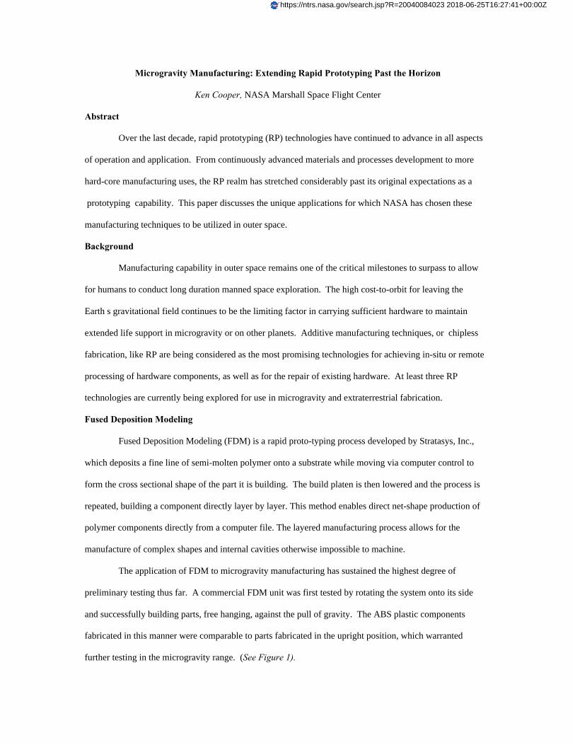
The application of FDM to microgravity manufacturing has sustained the highest degree of
preliminary testing thus far. A commercial FDM unit was first tested by rotating the system onto its side
and successfully building parts, free hanging, against the pull of gravity. The ABS plastic components
fabricated in this manner were comparable to parts fabricated in the upright position, which warranted
further testing in the microgravity range. (See Figure 1).
https://ntrs.nasa.gov/search.jsp?R=20040084023 2018-06-25T16:27:41+00:00Z
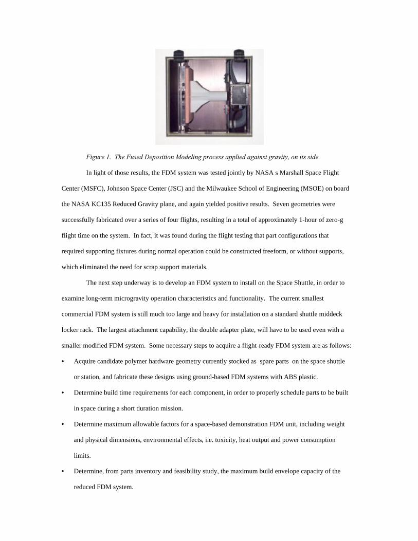
Figure 1. The Fused Deposition Modeling process applied against gravity, on its side.
In light of those results, the FDM system was tested jointly by NASA s Marshall Space Flight
Center (MSFC), Johnson Space Center (JSC) and the Milwaukee School of Engineering (MSOE) on board
the NASA KC135 Reduced Gravity plane, and again yielded positive results. Seven geometries were
successfully fabricated over a series of four flights, resulting in a total of approximately 1-hour of zero-g
flight time on the system. In fact, it was found during the flight testing that part configurations that
required supporting fixtures during normal operation could be constructed freeform, or without supports,
which eliminated the need for scrap support materials.
The next step underway is to develop an FDM system to install on the Space Shuttle, in order to
examine long-term microgravity operation characteristics and functionality. The current smallest
commercial FDM system is still much too large and heavy for installation on a standard shuttle middeck
locker rack. The largest attachment capability, the double adapter plate, will have to be used even with a
smaller modified FDM system. Some necessary steps to acquire a flight-ready FDM system are as follows:
• Acquire candidate polymer hardware geometry currently stocked as spare parts on the space shuttle
or station, and fabricate these designs using ground-based FDM systems with ABS plastic.
• Determine build time requirements for each component, in order to properly schedule parts to be built
in space during a short duration mission.
• Determine maximum allowable factors for a space-based demonstration FDM unit, including weight
and physical dimensions, environmental effects, i.e. toxicity, heat output and power consumption
limits.
• Determine, from parts inventory and feasibility study, the maximum build envelope capacity of the
reduced FDM system.

• Design and build part storage containers for safe return of test articles to Earth.
• Place the FDM demonstration flight unit in the queue for Space Shuttle flight experiments. The shuttle
flight would accomplish or establish the following: demonstration of long duration flight operation of
the FDM system, optimization of controls for astronaut friendly operation, allow for studying the
effects of surface tension on build capability, build shuttle spare part geometries as fabricated on the
ground for comparison and build microgravity-dependent part configurations to demonstrate advanced
manufacturing.
Once a flight system is completed and is used to build parts during a mission, NASA must test
components fabricated on the space shuttle for changes in mechanical properties, surface cohesion, layer-
to-layer bonding and physical properties (porosity, density, dimensional stability, etc.)
NASA will benefit in a variety of ways from the successful completion of this project. First,
fabrication of flight hardware spares in microgravity will lower flight weight, and particularly volume, due
to excessive spares inventory. Second, the creation of new hardware, i.e. modified designs for other in-
flight projects, will allow for innovation and optimization of flight experiments during a mission.
Selective Laser Sintering
Figure 2. A Selective Laser Sintering part just after fabrication.
Selective Laser Sintering (SLS) is a powder-based rapid prototyping process, which employs
scanning laser technology to fuse the build material in the shape of the part cross-sections, one on top of the
other. (See Figure 2). The current materials used with SLS include wax, polycarbonate, polyamide, nylon,
polymer matrix metals and polymer matrix sand. NASA is exploring the possibility of using SLS based
technology to form glass and structural materials from lunar and Martian soil, with the ultimate application
being the fabrication of spacecraft glass, large lenses or mirrors, and even glass bio-domes directly on the
surface of the moon and Mars using the existing soil. This would have a tremendous positive impact on
colonization, as the build materials required would not have to be transported from the Earth.
The SLS technology is probably the most versatile rapid prototyping process on the market as far
as polymer materials capability. SLS is largely researched for advanced materials capability in academia,
including direct metal sintering, direct ceramic powder sintering, and composite material RP development.
Some preliminary studies have been conducted at various universities on the formation of glass using laser
sintering technologies, using sand or lunar simulant. MSFC currently houses world-class experience in the
formation of glass from lunar soil, and the intent of this study is to draw on that capability along with the
in-house rapid prototyping expertise.
The next step will be to determine the feasibility of rapidly prototyping structural components
using SLS and lunar soil simulants as a build material. Studies must be conducted to determine laser power
requirements for small-spot glass formation, layer-to-layer bonding characteristics, and the effects of
scaling up the process for large-scale component fabrication.
Successful determination of sintering parameters will lead to materials properties testing and
International Space Station flight experiment development and demonstration. Power sources to be
considered are laser and focused solar energy. A KC135 Reduced Gravity demonstration will proceed the
space station flight to determine the feasibility of using this process in a low-gravity environment.
Laser Engineered Net Shaping
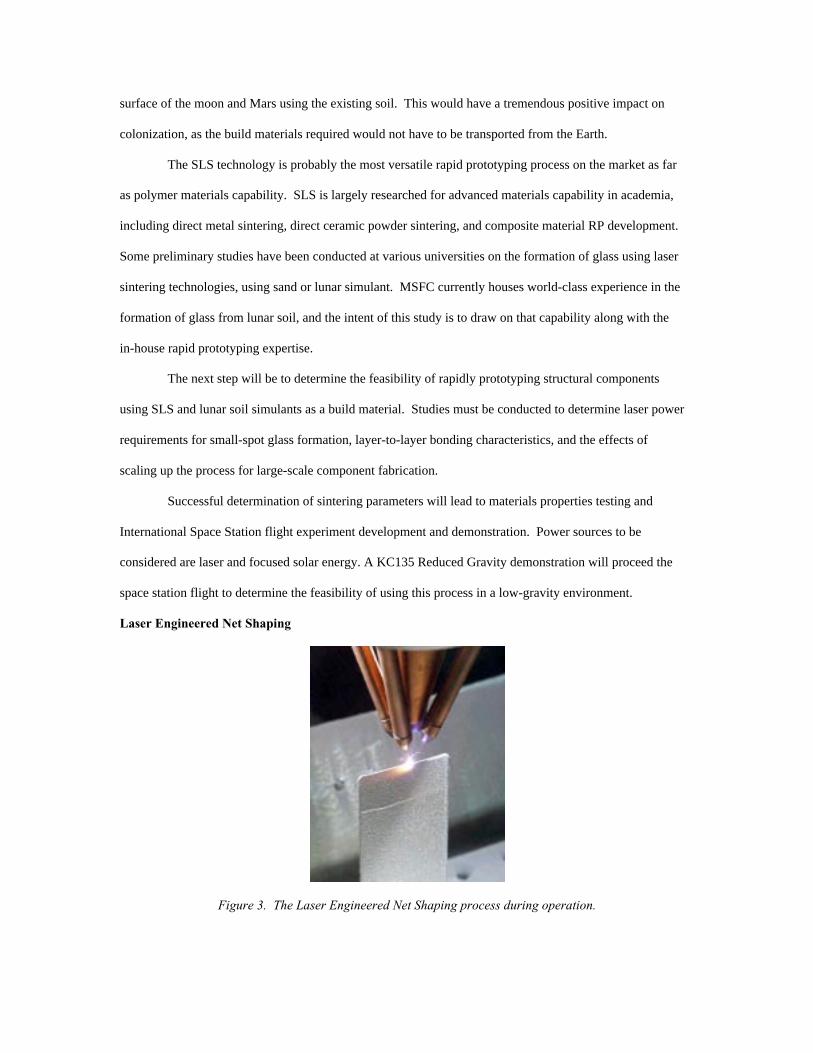
Figure 3. The Laser Engineered Net Shaping process during operation.
Laser Engineered Net Shaping (LENS) is a new rapid prototyping process developed by Sandia
National Laboratories and marketed by Optomec Design Company, which sprays a fine line of metal
powder into a moving, focused laser, building a component directly layer by layer. (See Figure 3). This
method enables direct near-net-shape production of metallic components directly from a computer file. The
layered manufacturing process allows for the manufacture of complex shapes and internal cavities
otherwise impossible to machine. NASA will exploit the benefits of the LENS technique to quickly and
inexpensively produce replacement components or repair broken hardware in a space shuttle or space
station environment.
The LENS technology has been in operation for a very short time, although it has been tested
against the pull of gravity by one of the current users of the system. In this application, the LENS head was
placed on a multi-axis robotic arm, which allowed for the fabrication of part components even in upside-
down situations. Additions were made to the system to keep powder overspray from accumulating on the
laser lens, which would also be necessary in a microgravity environment. The next step will be to build a
smaller, simpler LENS system in order to proof the feasibility of operation in a microgravity environment.
As in the FDM process, there a various steps to accomplish a flight-ready LENS-type system, including:
• NASA must acquire candidate hardware component geometry currently stocked as spare parts on the
space shuttle or station, and fabricate these designs using a ground-based LENS system with a suitable
metal, i.e. stainless steel or aluminum.
• Determine maximum allowable factors for a space-based demonstration LENS unit, including weight,
size and power consumption limits.
• Determine, from parts inventory and feasibility study, the maximum build envelope capacity of the
reduced LENS system, in addition to most suitable build materials for microgravity, powder
reclamation capability, and part removal from platen options.
• Fabricate a LENS demonstration flight unit.
After a flight unit is prepared, NASA must conduct flight feasibility studies using the NASA KC135
Reduced Gravity Flight Test and analyze the parts fabricated in Reduced Gravity Flight Test for
consistency with ground-based fabricated components to determine if any modifications will be required
prior to shuttle flight. NASA will then place the LENS demonstration flight unit in the queue for Space
Shuttle flight experiments, finally to test the components fabricated on the space shuttle for changes in
mechanical properties.
NASA will benefit in a variety of ways from the successful completion of the LENS project. First,
fabrication of flight hardware spares in microgravity will become a reality. Second, the repair of damaged
or broken components may also be accomplished without affecting the materials properties of the repaired
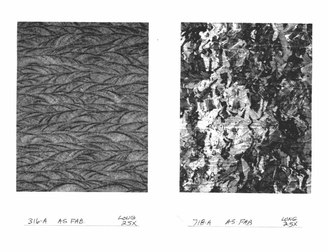
component. In addition, preliminary NASA studies of LENS-fabricated components have confirmed that
the mechanical properties are actually stronger than wrought-annealed properties. This will lead to the use
of more economical materials for higher performance applications.
NASA s advanced LENS system for use on space station will utilize an incorporated vision system for
component inspection and selective repair, multiple build materials capabilities to meet various processing
needs, low power (i.e. diode laser) consumption with maximum output, 100% powder reclamation
capability and an integrated platen/part separation system. NASA is also currently pursuing development
of hand-held LENS repair units for the regeneration of damaged spacecraft hulls during space flight. These
systems will smart scan spacecraft hull surfaces for micro-meteorite damage detection and repair, using
advanced digital imaging and void recognition software, and will selectively repair defects with parent
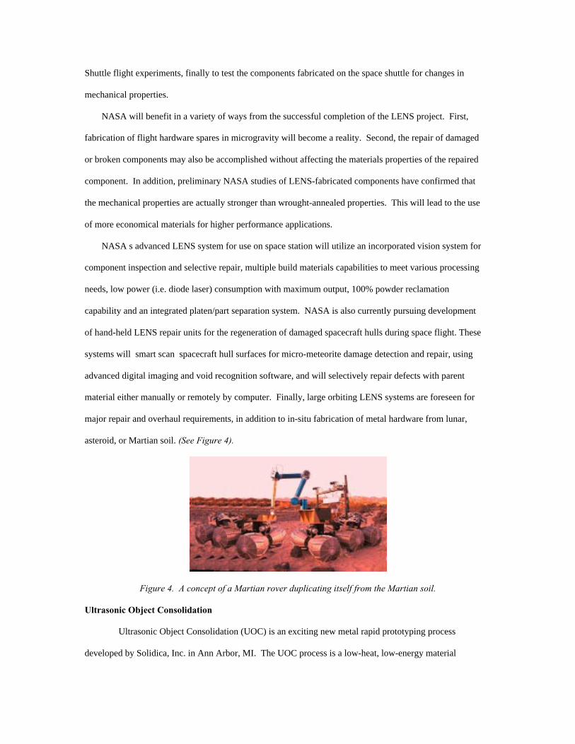
material either manually or remotely by computer. Finally, large orbiting LENS systems are foreseen for
major repair and overhaul requirements, in addition to in-situ fabrication of metal hardware from lunar,
asteroid, or Martian soil. (See Figure 4).
Figure 4. A concept of a Martian rover duplicating itself from the Martian soil.
Ultrasonic Object Consolidation
Ultrasonic Object Consolidation (UOC) is an exciting new metal rapid prototyping process
developed by Solidica, Inc. in Ann Arbor, MI. The UOC process is a low-heat, low-energy material

joining technique that shows the highest promise for fabricating aluminum or titanium hardware in
microgravity. The process works on the same principal as solid state welding currently used in electronics
manufacturing. Two thin layers of material are brought into contact under pressure, and are then submitted
to ultrasonic vibration between them (on the order of a few microns). The rubbing action causes the oxide
layers of each material to break away, exposing two atomic-clean metal surfaces to each other, causing a
solid-state weld. Figure 5 demonstrates the UOC process.
Figure 5. A Description of the Ultrasonic Object Consolidation (UOC) process from Solidica.
The amount of heat generated is negligible, and the energy and forces required to make a bond on
thin material are very low as well. NASA/MSFC is currently working with Solidica to develop a machine
based on this principal that will potentially be adaptable to use in microgravity. The main issues to be
addressed for adaptation will then be system size (volume), and the noise/vibration effects.
Laser Engineering Net Shaping
• Task- Present some of RP Lab's findingsand experiences with this technology.
• Standards- The audience; Experiment thevariables of this machine s operation.
• Conditions- 45 minutes, lecture and PowerPoint presentation in classroomenvironment.
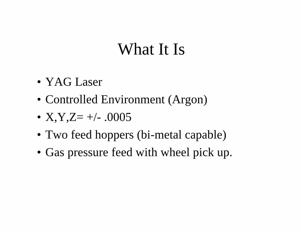
What It Is
• YAG Laser
• Controlled Environment (Argon)
• X,Y,Z= +/- .0005
• Two feed hoppers (bi-metal capable)
• Gas pressure feed with wheel pick up.

What It Isn t
• Perfected
• 100% Efficient
• Maintenance Free
• Cheap
• Real Smart

Our Machine
• LENS 750 byOPTOMEC
• 1999 Model
• Originally modifiedwith powder recoverysystem & weld poolmonitor (sinceremoved)
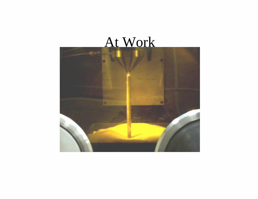
At Work
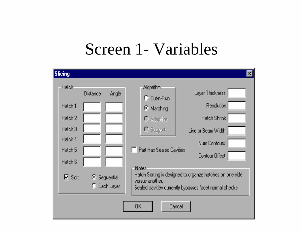
Screen 1- Variables

Screen 2- Variables

Considerations for ExperimentPlanning
Melting Temperatures of Constituents?
Oxidation & Effects?
Toxicity & Off-Gassing?
Spherical Diameter and Gradient?
Hydro & Feed Compatibility?

Materials We Have Tried-1
SS316 stainless steel success
Inco718 (nickel based alloy) success
Narloy Z (copper-silver alloy)+ Alumina Al2O3 didn’t deposit
Copper Chrome Niobium didn’t deposit
Aluminum 2026 didn’t deposit
Inco718 + Alumina Al2O3 (mechanical mix) deposit, but nothomogeneous
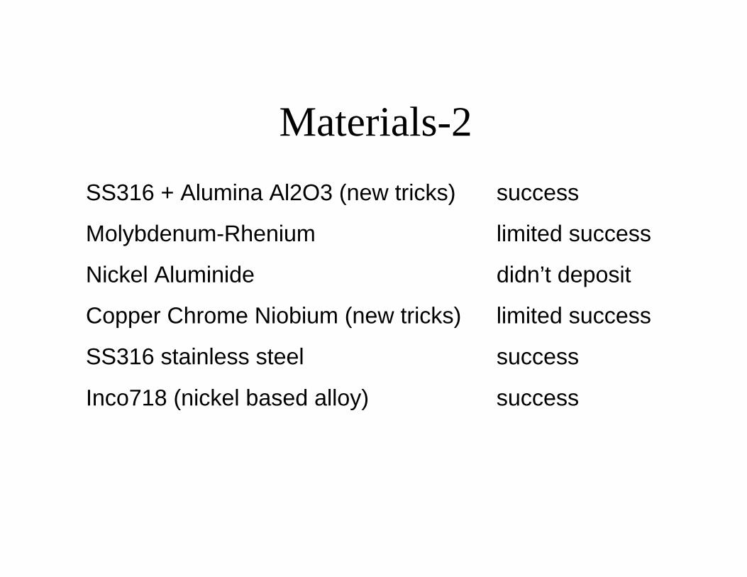
Materials-2
SS316 + Alumina Al2O3 (new tricks) success
Molybdenum-Rhenium limited success
Nickel Aluminide didn’t deposit
Copper Chrome Niobium (new tricks) limited success
SS316 stainless steel success
Inco718 (nickel based alloy) success

Materials-3Narloy Z (copper-silver alloy) + Alumina Al2O3 didn’t deposit
Copper Chrome Niobium didn’t deposit
Aluminum 2026 didn’t deposit
Inco718 + Alumina Al2O3 (mechanical mix) deposit, but not homogeneous

Materials-4
SS316 + Alumina Al2O3 (new tricks) success
Molybdenum-Rhenium limited success
Nickel Aluminide didn’t deposit
Copper Chrome Niobium (new tricks) limited success
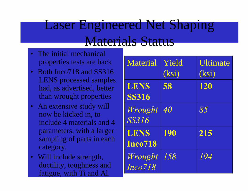
Laser Engineered Net ShapingMaterials Status
• The initial mechanicalproperties tests are back
• Both Inco718 and SS316LENS processed sampleshad, as advertised, betterthan wrought properties
• An extensive study willnow be kicked in, toinclude 4 materials and 4parameters, with a largersampling of parts in eachcategory.
• Will include strength,ductility, toughness andfatigue, with Ti and Al.
194158WroughtInco718
215190LENSInco718
8540WroughtSS316
12058LENSSS316
Ultimate(ksi)
Yield(ksi)
Material

Wrought vs. Deposited
194158Wrought Inco718
215190Inconel 718
8540Wrought SS316
12058Stainless Steel 316
Ultimate (ksi)Yield (ksi)
MSFC Laser Engineered Net Shaping Materials Properties

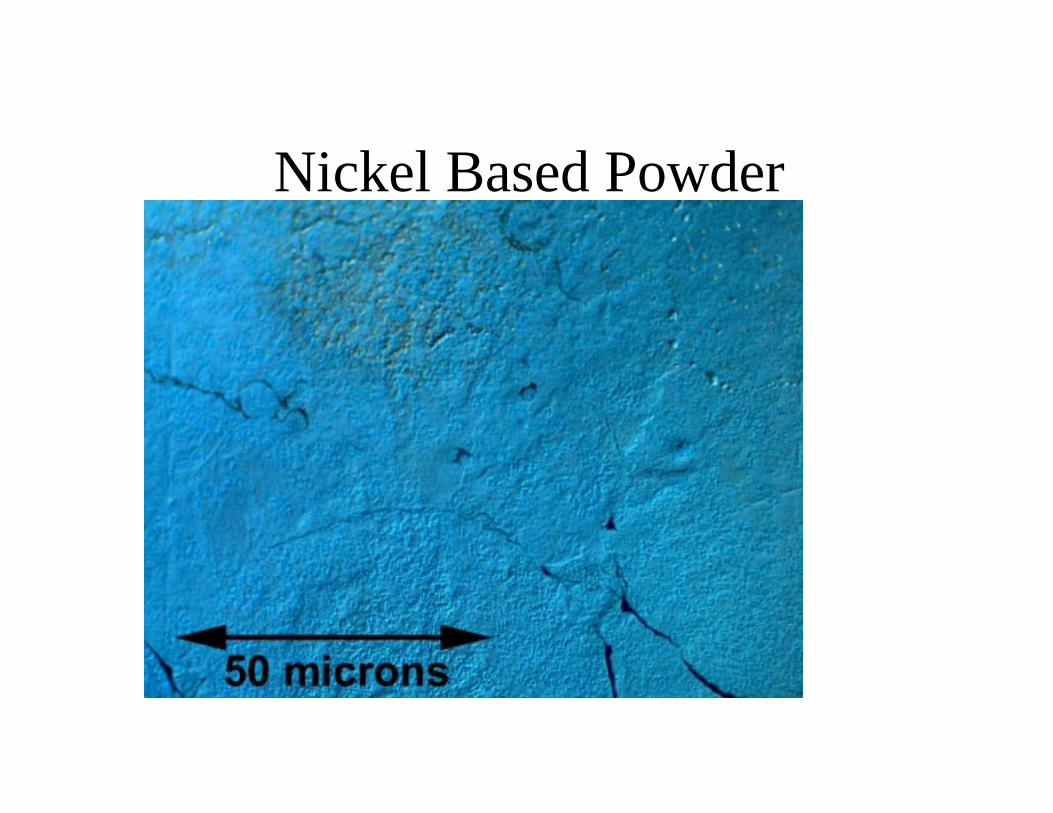
Nickel Based Powder

Copper Based Powder

For More Information
(256) 544-8591
(256) 544-1041
http://ncam.msfc.nasa.gov
http://www.optomec.com
Top Related