


Languages
Pages
Legal


Edition 2021 Australia
MICHELIN Truck and Bus TyreTECHNICAL DATABOOK

SAFETY WARNINGS
BE SURE TO READ THE SAFETYINFORMATION PROVIDED HEREIN AS SERIOUS INJURY OR DEATH CAN RESULT FROM FAILURE TO FOLLOW SAFETY WARNINGS
WARNING: Tyre and rim servicing can be dangerous and must be done only by trained personnel using proper tools and procedures. Failure to read and comply with all procedures may result in serious injury or death to you or others.
WARNING: Re-inflation of any type of tyre and rim assembly that has been operated in a run-flat or underinflated condition (80% or less of recommended operating pressure) can result in serious injury or death. The tyre may be damaged on the inside and can explode while you are adding air. The rim parts may be worn, damaged or dislodged and can explosively separate.
WARNING: Use of gasoline, petrol or any other flammable material to lubricate, seal or seat the beads of a tyre can cause the tyre to explode or can cause the explosive separation of the tyre/rim assembly resulting in serious injury or death. The use of any flammable material during tyre servicing is absolutely prohibited.
WARNING: Any inflated tyre mounted on a rim contains explosive energy. The use of damaged, mismatched or improperly assembled tyre/rim parts can cause the assembly to burst apart with explosive force. If you are struck by an exploding tyre, rim part or the air blast, you can be seriously injured or killed.
WARNING: Re-assembly and inflation of mismatched rim parts can result in serious injury or death. Just because parts fit together does not mean they belong together. Check for proper matching of all rim parts before putting any parts together.
WARNING: Mismatching tyre and rim diameters is dangerous. A mismatched tyre and rim assembly may explode and can result in serious injury or death. This warning applies to any combination of mismatched components. Never assemble a tyre and rim unless you have positively identified and correctly matched the parts.

1TYRE KNOWLEDGE
• Radial tyre components• Sidewall design• How to read tyre marking• InFLation Pressure
02
0304
06
3Appendix
• Tube & Flap assembly• Truck and Bus Wheel• Accessories• Conversion Table• General Information
7478
80
8285
2Technical characteristics table and product offer
• User focus, Usage focus• Technical characteristics table
0814 - 71
Contents


1TYRE KNOWLEDGE
• Radial tyre components• Sidewall design• How to read tyre marking• InFLation Pressure
04
TY
RE
KN
OW
LE
DG
E
0203
06

Tread Pattern
Tread Groove
Cushion Rubber
Protector Ply
Working Plies (belt)
Casing Ply
Bead ChaferInner Liner
Bead Toe
Bead Heel
Bead Wire
Shoulder Area
Sidewall Area
Bead Area
Crown Area
ComponentsTread Pattern
Tread Groove
Cushion Rubber
Protector Ply
Working Plies (belt)
Casing Ply
Bead ChaferInner Liner
Bead Toe
Crown Area
Shoulder Area
Sidewall Area
Bead Area
Infini Coil®
Stabilizing Ply
Bead Heel
Bead Wire
MICHELIN
02
1Tyre Knowledge
Radial Tyre Components

YOUR BRAND
YOUR APPLICATION
YOUR EQUIPMENT
295/80R22.5 D = Drive axle
275/70R22.5 Z = All position 455/55R22.5 T = Trailer axle
385/55R22.5 F = Front axle
This marking indicates the tyre is designed for steer axles.F
This marking indicates the tyre is designed for drive axles.D
This marking (<<Z>>) indicates the tyre is designed for all positions whichincludes steer, drive, free rolling, and trailer axles.
Z
This marking indicates the tyre is designed for trailer axles.Tyre with marking (<<T>>) is specifically developed for trailer and semi-trailerfitments and is not suitable for front axle usage.
T
03
MICHELIN Truck & Bus TyresNew Sidewall Design
TY
RE
KN
OW
LE
DG
E

1Tyre Knowledge
147M
150
NOITCART
43 11
1
2
3
4
5
6
7
8
9
10
11
12
1314
15
17
18
16
19
20
21
22
23
24
13 Place for logistic information: vignette, barcode& matricule number, ex: PRZ6596G
14 DOT: Department of transport.The last 4 numbers indicate tyre manufacturing.
15 Tyre evolution number: indicates production date
16 Brazil or China homologation
17 Option name: indicates tyre optional benefit.
18 Range Name: indicates tyre usage (see naming chart).
19 Usage Pictogram: illustrates tyre common usage
20 “Brand tire here”: free space for hot branding
21 X® symbol of MICHELIN radial tyre, it's a registeredbrand
22 E2...: CEE homologation number
23 MICHELIN registered brand
24 Warning: gives user information
1 MICHELIN brand logo
3 Tyre architecture
4 M+S Mud and Snow & 3PMSF picto
5 Traction new regulation (drive tyre) or FRT,free rolling tyre (trailer only tyre)
6 Specific code
7 Tyre position code (Letter F for Front axle, D forDrive, T for Trailer, Z for all axle ...) illustrated ona truck silhouette (arrow indicates axle position)
8 Tyre Size9 Indicates added load and speed index (see chart)
11 Load and speed index
12 Made in...: indicates where the tyre has beenmanufactured
10 Radial, tubeless, regroovable
2 Max load max press and max speed. US regulation
How to Read Tyre Marking
04

Tyre Marking Detailed Description
05
TY
RE
KN
OW
LE
DG
E
Speed symbol and load index
Speed symbolSpeed
mph km/h
A1 3 5
A2 6 10
A3 9 15
A4 12 20
A5 16 25
A6 19 30
A7 22 35
A8 25 40
B 31 50
C 37 60
D 40 65
E 43 70
F 50 80
G 56 90
J 62 100
K 68 110
L 74 120
M 81 130
N 87 140
Index Load kg Index Load kg Index Load kg Index Load kg
100 800 123 1550 146 3000 169 5800
101 825 124 1600 147 3075 170 6000
102 850 125 1650 148 3150 171 6150
103 875 126 1700 149 3250 172 6300
104 900 127 1750 150 3350 173 6500
105 925 128 1800 151 3450 174 6700
106 950 129 1850 152 3550 175 6900
107 975 130 1900 153 3650 176 7100
108 1000 131 1950 154 3750 177 7300
109 1030 132 2000 155 3875 178 7500
110 1060 133 2060 156 4000 179 7750
111 1090 134 2120 157 4125 180 8000
112 1120 135 2180 158 4250 181 8250
113 1150 136 2240 159 4375 182 8500
114 1180 137 2300 160 4500 183 8750
115 1215 138 2360 161 4625 184 9000
116 1250 139 2430 162 4750 185 9250
117 1285 140 2500 163 4875 186 9500
118 1320 141 2575 164 5000 187 9750
119 1360 142 2650 165 5150 188 10000
120 1400 143 2725 166 5300 189 10300
121 1450 144 2800 167 5450 190 10600
122 1500 145 2900 168 5600 191 10900
IMPORTANT :allowed vehicle speed and loading.
Load Capacity Index: These numerical values are designed to correspond to a load value listed in a table similar to excerpt shown right. For a omplete Load Capacity Index table, see page 85 in the appendix.
Speed Symbols: These alpha numeric symbols correspond to a maximum speed the tyre is designed for continuous operation. For a complete peed Symbol table, see page 85 in the appendix.
Overall dimensions
Rim diameter.
Minimum dual spacing.
Static deflection (R-R’).
Section height.
Ø
E
e
H
Section width whenmeasured onstandard rim
Free radius.
Laden radius.
S
R
R’
Free diameter (Rx2).D
Unique point
A number of truck tyre sizes carry a second load speed index marked on the sidewall. This is known as the«Unique Point» that is located after the main load index as shown below
For these sizes, the «Unique Point» provides additional load speed operatingconditions in order to satisfy particular requirements.
IMPORTANT : Load variances based on speed do not apply to the additionalcouple load index / speed symbol of the unique point.
135/133 G133
132J

1Tyre Knowledge
06
InFLation Pressure
UNDERINFLATIONCauses abnormal tyre deflection, which buildsup heat and causesirregular wear. Similar tothe rim being too wide.
OVERINFLATIONCauses tyre to run hard andbe more vulnerable to impacts.It also causes irregular wear.Similar to the rim beingtoo narrow.
PROPER INFLATIONThe correct profile for fullcontact with the roadpromotes traction, brakingcapability and safety.
The most critical factor in tyre maintenance is proper inflation. No tyre or tube is completely impervious to loss of air pressure. To avoid the hazards of under inflation, lost-air must be replaced. Inflation pressure has a direct impact in tyre performance - both tread life and endurance - as shown in the following charts :

2Technical characteristics table and product offer
• User focus, Usage focus• Technical characteristics table
Te
ch
nic
al
ch
ar
ac
te
ris
tic
s t
ab
le
a
nd
pr
od
uc
t o
ff
er08
14 - 71
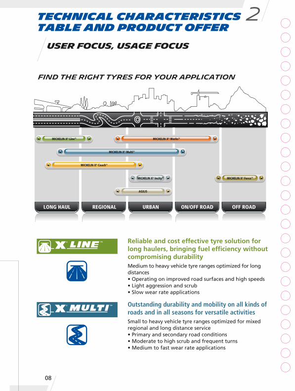
LONG HAUL REGIONAL URBAN ON/OFF ROAD OFF ROAD
MICHELIN X® CoachTM
MICHELIN X® MultiTM
MICHELIN X® WorksTMMICHELIN X® LineTM
AGILIS
MICHELIN X® ForceTMMICHELIN X® IncityTM
Technical characteristicstable and product offer
2
User Focus, Usage Focus
FIND THE RIGHT TYRES FOR YOUR APPLICATION
Reliable and cost effective tyre solution forlong haulers, bringing fuel efficiency withoutcompromising durabilityMedium to heavy vehicle tyre ranges optimized for longdistances• Operating on improved road surfaces and high speeds• Light aggression and scrub• Slow wear rate applications
Outstanding durability and mobility on all kinds ofroads and in all seasons for versatile activitiesSmall to heavy vehicle tyre ranges optimized for mixedregional and long distance service• Primary and secondary road conditions• Moderate to high scrub and frequent turns• Medium to fast wear rate applications
08
09
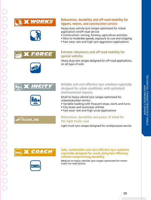
Robustness, durability and off-road mobility fortippers, mixers, and construction serviceHeavy duty vehicle tyre ranges optimized for mixedapplication on/off road service• Construction, mining, forestry, agriculture activities• Slow to moderate speeds, exposure to cuts and chipping• Fast wear rate and high tyre aggression applications
Extreme robustness and off-road mobility forspecial vehiclesHeavy duty tyre ranges designed for off-road applications,on all type of soils
Reliable and cost effective tyre solutions especiallydesigned for urban conditions, with optimizedenvironmental impactsSmall to heavy vehicle tyre ranges optimized forurban/suburban service• Variable loading with frequent stops, starts and turns• City buses and municipal utilities• Fast wear rate and high scrub applications
Safe, comfortable and cost effective tyre solutionsespecially designed for coach, bring fuel efficiencywithout compromising durabilityMedium to heavy vehicles tyre ranges optimized for motorcoach on-road service
Robustness, durability and peace of mind forthe light trucks userLight truck tyre ranges designed for multipurpose service
Te
ch
nic
al
ch
ar
ac
te
ris
tic
s t
ab
le
a
nd
pr
od
uc
t o
ff
er
Technical characteristicstable and product offer
2
10
MICHELINX MULTI HD Z
MICHELINX MULTIWAY XZE R
MICHELINXZE 3 R
MICHELINX MULTIWAY 3D XZE
MICHELINXZE
MICHELINXZN MIX ENERGY
MICHELINXJW 4+
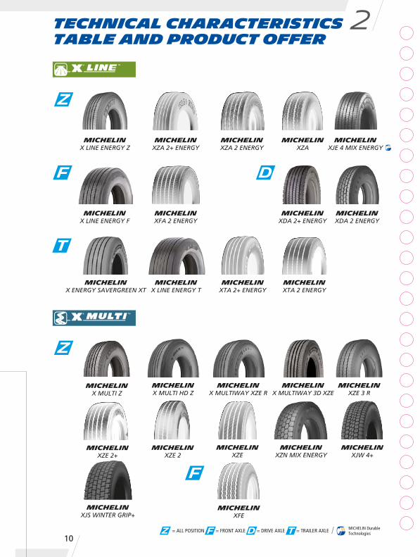
MICHELINXZA 2 ENERGY
MICHELINX LINE ENERGY Z
MICHELINXZA
MICHELINXJE 4 MIX ENERGY
MICHELINXFA 2 ENERGY
MICHELINX LINE ENERGY F
MICHELINXDA 2 ENERGY
MICHELINXDA 2+ ENERGY
MICHELINX ENERGY SAVERGREEN XT
MICHELINX LINE ENERGY T
MICHELINXTA 2+ ENERGY
MICHELINXTA 2 ENERGY
MICHELINXZA 2+ ENERGY
Z
F D
T
Z
= ALL POSITION = FRONT AXLE = DRIVE AXLE = TRAILER AXLE MICHELIN DurableTechnologiesZ F D T
MICHELINXFE
F
MICHELINXZE 2
MICHELINX MULTI Z
MICHELINXJS WINTER GRIP+
MICHELINXZE 2+
11
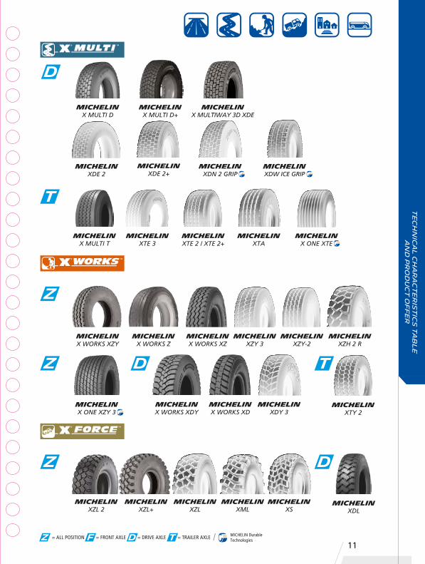
MICHELINXZL
MICHELINXZL 2
MICHELINXZL+
MICHELINXML
MICHELINXS
MICHELINX WORKS XZY
MICHELINX WORKS Z
MICHELINX WORKS XZ
MICHELINXZY 3
MICHELINXZY-2
MICHELINXZH 2 R
MICHELINX ONE XZY 3
MICHELINXTA
MICHELINXTE 2 / XTE 2+
MICHELINXTE 3
MICHELINX ONE XTE
MICHELINX MULTIWAY 3D XDE
MICHELINXDE 2
MICHELINXDN 2 GRIP
MICHELINXDW ICE GRIP
= ALL POSITION = FRONT AXLE = DRIVE AXLE = TRAILER AXLE MICHELIN DurableTechnologiesZ F D T
D
T
Z
Z
Z
MICHELINXDL
D
MICHELINX WORKS XDY
MICHELINX WORKS XD
MICHELINXDY 3
D
MICHELINXTY 2
T
MICHELINX MULTI T
Te
ch
nic
al
ch
ar
ac
te
ris
tic
s t
ab
le
a
nd
pr
od
uc
t o
ff
er
MICHELINX MULTI D
MICHELINX MULTI D+
MICHELINXDE 2+

MICHELIN AGILIS
MICHELINX COACH ENERGY Z
MICHELINAGILIS HD
MICHELINXZA
MICHELINXJE 4 MIX ENERGY
MICHELINXZY 3
MICHELINXDW Ice Grip
MICHELIN X INCITY Z
MICHELINXZU 3+
MICHELIN XZU 3
MICHELINXZU ENERGY
MICHELINXZU 2T
MICHELINX ONE XZU S
Technical characteristicstable and product offer
2
12
Z
Z
Z
= ALL POSITION = FRONT AXLE = DRIVE AXLE = TRAILER AXLE MICHELIN DurableTechnologiesZ F D T
D
MICHELINX COACH XD

Te
ch
nic
al
ch
ar
ac
te
ris
tic
s t
ab
le
a
nd
pr
od
uc
t o
ff
er
Te
ch
nic
al C
ha
ra
ct
er
ist
ics
15
- 1
6 I
nc
he
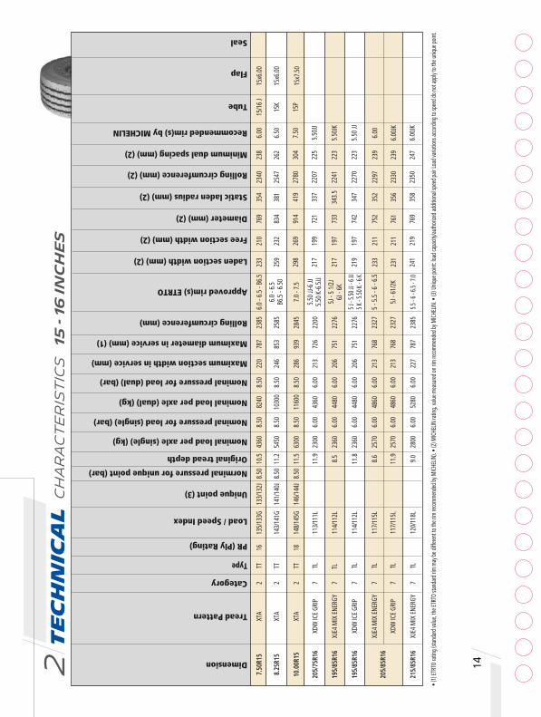
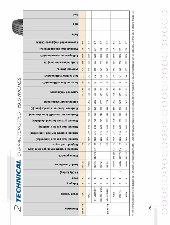
s2 Dimension
Tread Pattern
Category
Type
PR (Ply Rating)
Load / Speed Index
Norminal pressure for unique point (bar)
Original tread depth
Nominal load per axle (single) (kg)
Nominal pressure for load (single) (bar)
Nominal load per axle (dual) (kg)
Nominal pressure for load (dual) (bar)
Maximum section width in service (mm)
Maximum diameter in service (mm) (1)
Rolling circumference (mm)
Approved rim(s) ETRTO
Laden section width (mm) (2)
Free section width (mm) (2)
Diameter (mm) (2)
Static laden radius (mm) (2)
Rolling circumference (mm) (2)
Minimum dual spacing (mm) (2)
Recommended rim(s) by MICHELIN
Tube
Flap
Seal
Unique point (3)
23
3 21
0 76
9 35
4 23
40
238
6.00
15
/16
J 15
x6.0
0
25
9 23
2 83
4 38
1 25
47
262
6.50
15
K 15
x6.0
0
29
8 26
9 91
4 41
9 27
80
304
7.50
15
P 15
x7.5
0
21
7 19
9 72
1 33
7 22
07
225
5.50
JJ
21
7 19
7 73
3 34
3.5
2241
22
3 5.
50JK
21
9 19
7 74
2 34
7 22
70
223
5.50
JJ
23
3 21
1 75
2 35
2 22
97
239
6.00
23
1 21
1 76
1 35
6 23
30
239
6.00
JK
24
1 21
9 76
9 35
8 23
50
247
6.00
JK
7.
50R1
5 XT
A 2
TT
16
135/
133G
13
3/13
2J
8.50
10
.5
4360
8.
50
8240
8.
50
220
787
2385
6.
0 - 6
.5 -
B6.5
8.
25R1
5 XT
A 2
TT
14
3/14
1G
141/
140J
8.
50
11.2
54
50
8.50
10
300
8.50
24
6 85
3 25
85
6.0
- 6.5
B6
.5 -
6.50
10
.00R
15
XTA
2 TT
18
14
8/14
5G
146/
144J
8.
50
11.5
63
00
8.50
11
600
8.50
28
6 93
9 28
45
7.0
- 7.5
20
5/75
R16
XDW
ICE
GRIP
7
TL
11
3/11
1L
11.9
23
00
6.00
43
60
6.00
21
3 72
6 22
00
5.50
JJ-6
JJ
5.50
K-6
.5JJ
19
5/85
R16
XJE4
MIX
ENE
RGY
7 TL
114/
112L
8.
5 23
60
6.00
44
80
6.00
20
6 75
1 22
76
5J -
5 1/
2J
6J
- 6K
19
5/85
R16
XDW
ICE
GRIP
7
TL
11
4/11
2L
11.8
23
60
6.00
44
80
6.00
20
6 75
1 22
76
5 J - 5
.50 JJ
- 6 JJ
5 K
- 5.50
K - 6
K
20
5/85
R16
XJE4
MIX
ENE
RGY
7 TL
117/
115L
8.
6 25
70
6.00
48
60
6.00
21
3 76
8 23
27
5 - 5
.5 -
6 - 6
.5
XDW
ICE
GRIP
7
TL
11
7/11
5L
11.9
25
70
6.00
48
60
6.00
21
3 76
8 23
27
5J -
61/2
K
21
5/85
R16
XJE4
MIX
ENE
RGY
7 TL
120/
118L
9.
0 28
00
6.00
52
80
6.00
22
7 78
7 23
85
5.5 - 6
- 6.5
- 7.0
• (1)
ETRT
O ra
ting (
stand
ard v
alue,
the E
TRTO
stan
dard
rim
may b
e diff
erent
to th
e rim
reco
mmen
ded b
y MIC
HELIN
). • (
2) M
ICHE
LIN ra
ting,
value
mea
sured
on ri
m rec
omme
nded
by M
ICHE
LIN. •
(3) U
nique
point
: load
capa
city/a
utho
rized
addit
ional
spee
d pair
Load
varia
tions
acco
rding
to sp
eed d
o not
apply
to th
e uniq
ue po
int.
14

15
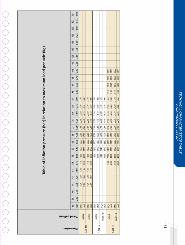
Tab
le o
f in
flat
ion
pre
ssu
re (
bar
) in
rel
atio
n t
o m
axim
um
load
per
axl
e (k
g)
Dimension
Tread pattern
7.5
0R15
XT
A
8.2
5R15
XT
A
1
0.00
R15
XTA
205/
75R1
6 XD
W IC
E GR
IP
195/
85R1
6 XJ
E4 M
IX EN
ERGY
195/
85R1
6 XD
W IC
E GR
IP
205/
85R1
6 XJE4
MIX EN
ERGY
XDW
ICE
GRIP
215/
85R1
6 XJ
E4 M
IX ENER
GY
29
50
3060
31
80
3300
34
20
3540
36
50
3770
38
90
4010
41
20
4240
43
60
5570
57
90
6010
62
40
6460
66
80
6900
71
30
7350
75
70
7790
80
20
8240
36
80
3830
39
80
4120
42
70
4420
45
70
4710
48
60
5010
51
60
5300
54
50
6960
72
40
7520
77
90
8070
83
50
8630
89
10
9190
94
60
9740
10
020
1030
0
4260
44
30
4600
47
70
4940
51
10
5280
54
50
5620
57
90
5960
61
30
6300
78
40
8150
84
60
8780
90
90
9410
97
20
1003
0 10
350
1066
0 10
970
1129
0 11
600
17
90
1870
19
60
2040
21
30
2210
23
00
3390
35
50
3710
38
80
4040
42
00
4360
18
40
1920
20
10
2100
21
90
2270
23
60
3480
36
50
3820
39
80
4150
43
10
4480
18
40
1920
20
10
2100
21
90
2270
23
60
3480
36
50
3820
39
80
4150
43
10
4480
20
00
2090
21
90
2280
23
80
2470
25
70
3780
39
60
4140
43
20
4500
46
80
4860
20
00
2090
21
90
2280
23
80
2470
25
70
3780
39
60
4140
43
20
4500
46
80
4860
21
80
2280
23
90
2490
25
90
2700
28
00
4110
43
00
4500
46
90
4890
50
80
5280
65
69
73
76
80
83
87
91
94
98
10
2 10
5 10
9 11
2 11
6
4.
50
4.75
5.
00
5.25
5.
50
5.75
6.
00
6.25
6.
50
6.75
7.
00
7.25
7.
50
7.75
8.
00
12
0 12
3 12
7 13
1
8.
25
8.50
8.
75
9.00
ps
i 36
40
44
47
51
54
58
62
ba
r 2.
50
2.75
3.
00
3.25
3.
50
3.75
4.
00
4.25
sin
gle
du
al
s
ingl
e
dual
sin
gle
dual
s
ingl
e
12
80
1360
14
50
1530
16
20
1700
du
al
24
20
2580
27
50
2910
30
70
3230
sin
gle
1310
14
00
1490
15
70
1660
17
50
dual
2490
26
50
2820
29
90
3150
33
20 s
ingl
e
13
10
1400
14
90
1570
16
60
1750
du
al
24
90
2650
28
20
2990
31
50
3320
sin
gle
1430
15
20
1620
17
10
1810
19
00
dual
2700
28
80
3060
32
40
3420
36
00 s
ingl
e
14
30
1520
16
20
1710
18
10
1900
du
al
27
00
2880
30
60
3240
34
20
3600
sin
gle
1560
16
60
1760
18
70
1970
20
70
dual
2930
31
30
3320
35
20
3720
39
10
Te
ch
nic
al
ch
ar
ac
te
ris
tic
s t
ab
le
a
nd
pr
od
uc
t o
ff
er

Te
ch
nic
al C
ha
ra
ct
er
ist
ics
15
- 1
6 I
nc
he
s2 16
• (1)
ETRT
O ra
ting (
stand
ard v
alue,
the E
TRTO
stan
dard
rim
may b
e diff
erent
to th
e rim
reco
mmen
ded b
y MIC
HELIN
). • (
2) M
ICHE
LIN ra
ting,
value
mea
sured
on ri
m rec
omme
nded
by M
ICHE
LIN. •
(3) U
nique
point
: load
capa
city/a
utho
rized
addit
ional
spee
d pair
Load
varia
tions
acco
rding
to sp
eed d
o not
apply
to th
e uniq
ue po
int.
Dimension
Tread Pattern
Category
Type
PR (Ply Rating)
Load / Speed Index
Norminal pressure for unique point (bar)
Original tread depth
Nominal load per axle (single) (kg)
Nominal pressure for load (single) (bar)
Nominal load per axle (dual) (kg)
Nominal pressure for load (dual) (bar)
Maximum section width in service (mm)
Maximum diameter in service (mm) (1)
Rolling circumference (mm)
Approved rim(s) ETRTO
Laden section width (mm) (2)
Free section width (mm) (2)
Diameter (mm) (2)
Static laden radius (mm) (2)
Rolling circumference (mm) (2)
Minimum dual spacing (mm) (2)
Recommended rim(s) by MICHELIN
Tube
Flap
Seal
Unique point (3)
7.
00 R
16
AG
ILIS
7 TL
16
11
7/11
3L
9.2
2570
6.
00
4600
6.
00
208
794
2406
4.
50E
- 5.0
0E
5.50
F - 6
.00G
AGILI
S 7
TL
12
117/
116L
9.
2 25
70
6.00
50
00
6.00
20
8 79
4 24
06
4.50
E - 5
.00E
5.
50F -
6.0
0G
7.
50R1
6 AG
ILIS
7 TL
14
12
2/12
1L
9.2
3000
7.
00
5800
7.
00
226
824
2497
5.
50F -
6.0
0G
6.50
H
AGILI
S HD
7
TL
14
122/
121L
10
.3
3000
7.
00
5800
7.
00
226
824
2497
5.
50F -
6.0
0G
6.
50H
8.25
R16
AGILI
S 7
TT
16
128/
126K
10
.5
3600
6.
75
6800
6.
75
239
878
2623
6.
00G
- 6.5
0H
AGILI
S HD
7
TT
16
128/
126K
11
.6
3600
6.
75
6800
6.
75
239
878
2623
6.
00G
- 6.5
0H
217
195
782
365.
5 23
88
221
5.50
F 16
J 16
x6.0
0
21
7 19
5 78
2 36
5 23
88
221
5.50
F 16
J 16
x6.0
0
23
1 20
9 80
0 37
5 24
50
237
6.00
G 16
J 16
x6.0
0
22
7 20
7 80
4 37
7 24
59
234
6.00
G 16
J 16
x6.0
0
25
6 23
2 85
8 40
0 26
19
263
6.50
H 16
K 16
x6.00
25
9 23
5 86
0 40
0.5
2627
26
5 6.
50H
16K
16x6
.00
Tab
le o
f in
flat
ion
pre
ssu
re (
bar
) in
rel
atio
n t
o m
axim
um
load
per
axl
e (k
g)
Dimension
Tread pattern
7.00
R16
AG
ILIS
AGILI
S
7.50
R16
AGILI
S
AGILI
S HD
8.25
R16
AGILI
S
AGILI
S HD
20
00
2090
21
90
2280
23
80
2470
25
70
3890
40
70
4260
44
40
4630
48
10
5000
20
00
2090
21
90
2280
23
80
2470
25
70
3890
40
70
4260
44
40
4630
48
10
5000
20
00
2090
21
90
2280
23
80
2470
25
70
3890
40
70
4260
44
40
4630
48
10
5000
20
00
2090
21
90
2280
23
80
2470
25
70
38
90
4070
42
60
4440
46
30
4810
50
00
2030
21
30
2230
23
20
2420
25
20
2610
27
10
2810
29
00
3000
39
30
4120
43
00
4490
46
80
4860
50
50
5240
54
30
5610
58
00
2030
21
30
2230
23
20
2420
25
20
2610
27
10
2810
29
00
3000
39
30
4120
43
00
4490
46
80
4860
50
50
5240
54
30
5610
58
00
65
69
73
76
80
83
87
91
94
98
10
2 10
5 10
9 11
2 11
6
4.
50
4.75
5.
00
5.25
5.
50
5.75
6.
00
6.25
6.
50
6.75
7.
00
7.25
7.
50
7.75
8.
00
12
0 12
3 12
7 13
1
8.
25
8.50
8.
75
9.00
ps
i 36
40
44
47
51
54
58
62
ba
r 2.
50
2.75
3.
00
3.25
3.
50
3.75
4.
00
4.25
sin
gle
1430
15
20
1620
17
10
1810
19
00
dual
2780
29
60
3150
33
30
3520
37
00 s
ingl
e
14
30
1520
16
20
1710
18
10
1900
du
al
27
80
2960
31
50
3330
35
20
3700
sin
gle
1840
19
40
dual
3550
37
40 s
ingl
e
18
40
1940
du
al
35
50
3740
sin
gle
21
60
2280
24
00
dual
40
80
4310
45
30 s
ingl
e
2160
22
80
2400
du
al
4080
43
10
4530
17
Te
ch
nic
al
ch
ar
ac
te
ris
tic
s t
ab
le
a
nd
pr
od
uc
t o
ff
er

Te
ch
nic
al C
ha
ra
ct
er
ist
ics
17
.5 I
nc
he
s2 18Dimension
Tread Pattern
Category
Type
PR (Ply Rating)
Load / Speed Index
Norminal pressure for unique point (bar)
Original tread depth
Nominal load per axle (single) (kg)
Nominal pressure for load (single) (bar)
Nominal load per axle (dual) (kg)
Nominal pressure for load (dual) (bar)
Maximum section width in service (mm)
Maximum diameter in service (mm) (1)
Rolling circumference (mm)
Approved rim(s) ETRTO
Laden section width (mm) (2)
Free section width (mm) (2)
Diameter (mm) (2)
Static laden radius (mm) (2)
Rolling circumference (mm) (2)
Minimum dual spacing (mm) (2)
Recommended rim(s) by MICHELIN
Tube
Flap
Seal
Unique point (3)
22
9 20
9 75
9 35
5 23
06
237
6.00
26
9 24
6 79
3 36
6 24
17
209
6.75
26
8 24
5 79
5 36
8 24
24
277
6.75
268
246
795
368
2415
27
8 6.
75
26
8 24
5 79
7 36
8 24
19
277
6.75
23
2 21
0 75
5 35
0 23
04
238
6.00
23
0 21
0 76
3 35
3 23
10
238
6.00
23
1 21
0 76
3 35
3 23
12
238
6.00
23
7 21
7 77
0 35
7 23
46
245
6.00
23
8 21
7 77
4 35
7 23
53
246
6.00
21
5/70
R17.
5 XZ
E2
6 TL
118/
116L
12
.8
2640
6.
00
5000
6.
00
222
759
2315
6.
00 -
6.75
X M
ULTI
Z
6 TL
136/
134M
12
.5
4480
8.
30
8480
8.
30
258
803
2449
6.
75 -
7.50
245/
70R1
7.5
XZE
2 6
TL
13
6/13
4M
13.5
44
80
8.00
84
80
8.00
25
8 80
3 24
49
6.75
- 7.
50
X M
ULTI
D
6 TL
136/
134M
12
.0
4480
8.
30
8480
8.
30
258
803
2449
6.
75
XDE
2 6
TL
13
6/13
4M
14.0
44
80
8.00
84
80
8.00
25
8 81
1 24
74
6.75
- 7.
50
X M
ULTI
Z
6 TL
14
12
4/12
2M
11.5
32
00
6.50
60
00
6.50
21
2 76
5 23
33
5.25 -
6.00
- 6.75
XZE
2 6
TL
12
4/12
2M
12.5
32
00
6.50
60
00
6.50
21
2 76
5 23
33
5.25 -
6.00
- 6.75
XDE
2 6
TL
12
4/12
2M
14.0
32
00
6.50
60
00
6.50
21
2 77
3 23
58
5.25 -
6.00
- 6.75
21
5/75
R17.
5 X
MUL
TI Z
6
TL
12
6/12
4M
11.5
34
00
6.90
64
00
6.90
22
0 77
9 23
76
6.00
- 6.
75
XZE
2 6
TL
12
6/12
4M
13.0
34
00
6.50
64
00
6.50
23
5 79
7 24
31
6.00
- 6.
75
205/
75R1
7.5
• (1)
ETRT
O ra
ting (
stand
ard v
alue,
the E
TRTO
stan
dard
rim
may b
e diff
erent
to th
e rim
reco
mmen
ded b
y MIC
HELIN
). • (
2) M
ICHE
LIN ra
ting,
value
mea
sured
on ri
m rec
omme
nded
by M
ICHE
LIN. •
(3) U
nique
point
: load
capa
city/a
utho
rized
addit
ional
spee
d pair
Load
varia
tions
acco
rding
to sp
eed d
o not
apply
to th
e uniq
ue po
int.
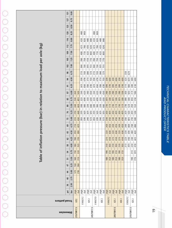
Tab
le o
f in
flat
ion
pre
ssu
re (
bar
) in
rel
atio
n t
o m
axim
um
load
per
axl
e (k
g)
Dimension
Tread pattern
20
50
2150
22
50
2350
24
40
2540
26
40
3890
40
70
4260
44
40
4630
48
10
5000
28
50
2970
30
90
3220
33
40
3470
35
90
3710
38
40
3960
40
80
4210
43
30
4460
5390
56
20
5860
60
90
6320
65
60
6790
70
30
7260
75
00
7730
79
60
8200
84
30
29
40
3070
32
00
3330
34
60
3580
37
10
3840
39
70
4100
42
20
4350
44
80
5570
58
10
6060
63
00
6540
67
80
7030
72
70
7510
77
50
8000
82
40
8480
28
50
2970
30
90
3220
33
40
3470
35
90
3710
38
40
3960
40
80
4210
43
30
4460
5390
56
20
5860
60
90
6320
65
60
6790
70
30
7260
75
00
7730
79
60
8200
84
30
29
40
3070
32
00
3330
34
60
3580
37
10
3840
39
70
4100
42
20
4350
44
80
5570
58
10
6060
63
00
6540
67
80
7030
72
70
7510
77
50
8000
82
40
8480
2320
24
30
2540
26
50
2760
28
70
2980
30
90
3200
43
40
4550
47
60
4970
51
70
5380
55
90
5790
60
00
2320
24
30
2540
26
50
2760
28
70
2980
30
90
3200
43
40
4550
47
60
4970
51
70
5380
55
90
5790
60
00
2320
24
30
2540
26
50
2760
28
70
2980
30
90
3200
43
40
4550
47
60
4970
51
70
5380
55
90
5790
60
00
23
30
2440
25
60
2670
27
80
2890
30
00
3110
32
20
3330
4390
46
00
4810
50
20
5230
54
40
5650
58
60
6070
62
70
24
60
2580
27
00
2810
29
30
3050
31
70
3280
34
00
4630
48
60
5080
53
00
5520
57
40
5960
61
80
6400
215
/70R
17.5
XZ
E2
X M
ULTI
Z 24
5/70
R17.
5
XZE
2
X M
ULTI
D
XDE
2
X M
ULTI
Z
XZE
2
XDE
2
X M
ULTI
Z
XZE
2
sin
gle
1470
15
60
1660
17
60
1860
19
60
dual
2780
29
60
3150
33
30
3520
37
00 s
ingl
e
du
al
sin
gle
dual
s
ingl
e
du
al
sin
gle
dual
s
ingl
e
18
80
1990
21
00
2210
dual
3520
37
20
3930
41
40 s
ingl
e
18
80
1990
21
00
2210
du
al
35
20
3720
39
30
4140
sin
gle
1880
19
90
2100
22
10
dual
3520
37
20
3930
41
40 s
ingl
e
21
10
2220
du
al
39
70
4180
sin
gle
1990
21
10
2230
23
40
dual
3750
39
70
4190
44
10
65
69
73
76
80
83
87
91
94
98
10
2 10
5 10
9 11
2 11
6
4.
50
4.75
5.
00
5.25
5.
50
5.75
6.
00
6.25
6.
50
6.75
7.
00
7.25
7.
50
7.75
8.
00
12
0 12
3 12
7 13
1
8.
25
8.50
8.
75
9.00
ps
i 36
40
44
47
51
54
58
62
ba
r 2.
50
2.75
3.
00
3.25
3.
50
3.75
4.
00
4.25
215
/75R
17.5
205/
75R1
7.5
19
Te
ch
nic
al
ch
ar
ac
te
ris
tic
s t
ab
le
a
nd
pr
od
uc
t o
ff
er

Te
ch
nic
al C
ha
ra
ct
er
ist
ics
17
.5 I
nc
he
s2 20Dimension
Tread Pattern
Category
Type
PR (Ply Rating)
Load / Speed Index
Norminal pressure for unique point (bar)
Original tread depth
Nominal load per axle (single) (kg)
Nominal load per axle (dual) (kg)
Nominal pressure for load (dual) (bar)
Rolling circumference (mm)
Approved rim(s) ETRTO
Laden section width (mm) (2)
Free section width (mm) (2)
Diameter (mm) (2)
Static laden radius (mm) (2)
Rolling circumference (mm) (2)
Minimum dual spacing (mm) (2)
Tube
Flap
Seal
Nominal pressure for load (single) (bar)
Maximum section width in service (mm)
Maximum diameter in service (mm) (1)
Recommended rim(s) by MICHELIN
Unique point (3)
23
6 21
5 77
7 35
9 23
70
243
6.00
22
6 20
8 76
6 35
4 23
53
6.
00
23
6 21
6 77
5 35
9 23
50
245
6.00
23
8 21
6 77
8 36
0 23
70
245
6.00
25
5 23
3 78
7 36
6 24
07
264
6.75
25
5 23
3 79
2 36
7 24
14
264
6.75
25
6 23
4 79
0 36
7 24
00
264
6.75
25
5 23
2 79
8 36
9 24
15
263
6.75
26
5 24
1 79
6 36
4 24
10
273
6.75
26
4 24
0 79
7 36
5 24
45
6.
75
24
3 24
1 79
9 37
1 24
39
272
6.75
26
1 23
9 80
5 37
3 24
51
271
6.75
26
2 24
0 50
1 37
0 24
33
272
6.75
26
2 23
9 80
7 37
3 24
47
271
6.75
XTE2
+ 2
TL
13
5/13
3J
12.2
43
60
8.50
82
40
8.50
22
0 77
9
6.00
- 6.
75
X M
ULTI
T2
2 TL
18
13
6/13
4J
12.2
44
80
9.00
84
80
9.00
22
0 77
9
6.00
- 6.
75
X M
ULTI
D
6 TL
126/
124M
13
.0
3400
6.
90
6400
6.
90
220
779
2376
6.
00 -
6.75
XDE
2 6
TL
12
6/12
4M
15.0
34
00
6.50
64
00
6.50
23
5 79
7 24
31
6.00
- 6.
75
X M
ULTI
Z
6 TL
129/
127M
11
.5
3700
7.
20
7000
7.
20
235
797
2431
6.
00 -
6.75
XZE
2 6
TL
12
9/12
7M
13.0
37
00
7.00
70
00
7.00
23
5 79
7 24
31
6.00
- 6.
75
X M
ULTI
D
6 TL
129/
127M
12
.5
3700
7.
20
7000
7.
20
235
797
2431
6.
00 -
6.75
XDE
2 6
TL
12
9/12
7M
15.0
37
00
7.00
70
00
7.00
23
5 80
3 24
49
6.00
- 6.
75
XTE2
+ 2
TL
14
3/14
1J
12.3
54
50
8.50
10
300
8.50
24
2 81
1
6.75
- 7.
50
X M
ULTI
T2
2 TL
18
14
3/14
1J
145/
145F
9.0
0 12
.6
5450
9.
00
1030
0 9.
00
242
811
6.
75 -
7.50
X M
ULTI
Z
6 TL
16
13
2/13
0M
12.5
40
00
7.60
76
00
7.60
24
2 81
1 24
74
6.75
- 7.
50
XZE
2 6
TL
13
2/13
0M
13.0
40
00
7.25
76
00
7.25
24
2 81
1 24
74
6.75
- 7.
50
X M
ULTI
D
6 TL
16
13
2/13
0M
12.5
40
00
7.60
68
00
7.60
24
2 81
1 24
74
6.75
- 7.
50
XDE
2 6
TL
13
2/13
0M
15.0
40
00
7.25
76
00
7.25
24
2 81
1 24
74
6.75
- 7.
50
• (1)
ETRT
O ra
ting (
stand
ard v
alue,
the E
TRTO
stan
dard
rim
may b
e diff
erent
to th
e rim
reco
mmen
ded b
y MIC
HELIN
). • (
2) M
ICHE
LIN ra
ting,
value
mea
sured
on ri
m rec
omme
nded
by M
ICHE
LIN. •
(3) U
nique
point
: load
capa
city/a
utho
rized
addit
ional
spee
d pair
Load
varia
tions
acco
rding
to sp
eed
do
not a
pply
to th
e uniq
ue po
int.
215/
75R1
7.5
235/
75R1
7.5
225/
75R1
7.5
21
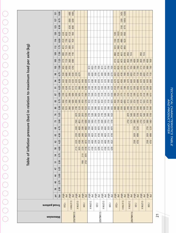
Tab
le o
f in
flat
ion
pre
ssu
re (
bar
) in
rel
atio
n t
o m
axim
um
load
per
axl
e (k
g)
Dimension
Tread pattern
XTE2
+
X M
ULTI
T2
X M
ULTI
D
XDE
2
X M
ULTI
Z
XZE
2
X M
ULTI
D
XDE
2
XTE2
+
X M
ULTI
T2
X M
ULTI
Z
XZE
2
X M
ULTI
D
XDE
2
sin
gle
du
al s
ingl
e
dual
sin
gle
2110
22
20
dual
3970
41
80 s
ingl
e
19
90
2110
22
30
2340
du
al
37
50
3970
41
90
4410
sin
gle
2210
23
30
dual
4180
44
00 s
ingl
e
22
70
2390
du
al
42
90
4520
sin
gle
2210
23
30
dual
4180
44
00 s
ingl
e
22
70
2390
du
al
42
90
4520
sin
gle
dual
s
ingl
e
du
al
sin
gle
dual
s
ingl
e
2500
du
al
4750
sin
gle
dual
s
ingl
e
2500
du
al
4750
29
50
3060
31
80
3300
34
20
3540
36
50
3770
38
90
4010
41
20
4240
5570
57
90
6010
62
40
6460
66
80
6900
71
30
7350
75
70
7790
80
20
28
60
2980
30
90
3210
33
20
3440
35
50
3660
37
80
3890
40
10
4120
42
40
4360
44
80
5460
56
80
5890
61
10
6330
65
40
6760
69
80
7190
74
10
7630
78
40
8080
82
80
8480
2330
24
40
2560
26
70
2780
28
90
3000
31
10
3220
33
30
4390
46
00
4810
50
20
5230
54
40
5650
58
60
6070
62
70
2460
25
80
2700
28
10
2930
30
50
3170
32
80
3400
4630
48
60
5080
53
00
5520
57
40
5960
61
80
6400
2440
25
60
2680
27
90
2910
30
30
3140
32
60
3370
34
90
3610
4620
48
40
5060
52
80
5500
57
20
5940
61
60
6380
66
00
6820
2510
26
30
2750
28
60
2980
31
00
3220
33
40
3460
35
80
3700
4740
49
70
5190
54
20
5650
58
70
6100
63
20
6550
67
70
7000
24
40
2560
26
80
2790
29
10
3030
31
40
3260
33
70
3490
36
10
46
20
4840
50
60
5280
55
00
5720
31
40
3260
33
70
3490
36
10
25
10
2630
27
50
2860
29
80
3100
32
20
3340
34
60
3580
37
00
47
40
4970
51
90
5420
56
50
5870
61
00
6320
65
50
6770
70
00
36
80
3830
39
80
4120
42
70
4420
45
70
4710
48
60
5010
51
60
5300
6960
72
40
7520
77
90
8070
83
50
8630
89
10
9190
94
60
9740
10
020
35
00
3630
37
70
3910
40
50
4190
43
30
4470
46
10
4750
48
80
5020
51
60
5300
54
50
6600
68
50
7110
73
80
7660
79
40
8200
84
50
8700
89
50
9220
95
00
9770
10
050
1030
0
2750
28
70
2990
31
10
3230
33
50
3470
35
90
3710
38
30
3950
52
30
5460
56
90
5920
61
40
6370
66
00
6830
70
50
7280
75
10
2630
27
50
2880
30
00
3130
32
50
3380
35
00
3630
37
50
3880
40
00
49
90
5230
54
60
5700
59
40
6180
64
10
6650
68
90
7130
73
60
7600
27
50
2870
29
90
3110
32
30
3350
34
70
3590
37
10
3830
39
50
5230
54
60
5690
59
20
6140
63
70
6600
68
30
7050
72
80
7510
26
30
2750
28
80
3000
31
30
3250
33
80
3500
36
30
3750
38
80
4000
4990
52
30
5460
57
00
5940
61
80
6410
66
50
6890
71
30
7360
76
00
65
69
73
76
80
83
87
91
94
98
10
2 10
5 10
9 11
2 11
6
4.
50
4.75
5.
00
5.25
5.
50
5.75
6.
00
6.25
6.
50
6.75
7.
00
7.25
7.
50
7.75
8.
00
12
0 12
3 12
7 13
1
8.
25
8.50
8.
75
9.00
ps
i 36
40
44
47
51
54
58
62
ba
r 2.
50
2.75
3.
00
3.25
3.
50
3.75
4.
00
4.25
215/
75R1
7.5
L
235/
75R1
7.5
225/
75R1
7.5
Te
ch
nic
al
ch
ar
ac
te
ris
tic
s t
ab
le
a
nd
pr
od
uc
t o
ff
er

Te
ch
nic
al C
ha
ra
ct
er
ist
ics
17
.5 I
nc
he
s2 22Dimension
Tread Pattern
Category
Type
PR (Ply Rating)
Load / Speed Index
Norminal pressure for unique point (bar)
Original tread depth
Nominal load per axle (single) (kg)
Nominal pressure for load (single) (bar)
Nominal load per axle (dual) (kg)
Nominal pressure for load (dual) (bar)
Maximum section width in service (mm)
Maximum diameter in service (mm) (1)
Rolling circumference (mm)
Approved rim(s) ETRTO
Laden section width (mm) (2)
Free section width (mm) (2)
Diameter (mm) (2)
Static laden radius (mm) (2)
Rolling circumference (mm) (2)
Minimum dual spacing (mm) (2)
Recommended rim(s) by MICHELIN
Tube
Flap
Seal
Unique point (3)
24
8 22
5 81
1 37
8 24
65
254
6.75
24
8 22
5 81
1 37
8 24
65
254
6.75
24
8 22
5 81
0 37
8 24
67
255
6.75
25
0 22
8 81
0 37
8 24
80
258
6.75
25
1 22
8 81
0 37
8 24
80
258
6.75
22
1 20
0 80
2 37
2 24
47
227
5.25
22
2 20
0 80
6 37
4 24
59
227
5.25
22
0 20
0 80
6 37
4 24
60
227
5.25
XZN+
MIX
ENE
RGY
6 TL
14
12
3/12
2L
11.8
31
00
6.00
60
00
6.00
22
8 81
0 24
71
6.00
- 6.
75
XZN
MIX
ENE
RGY
6 TL
14
12
3/12
2L
11.8
31
00
6.00
60
00
6.00
22
8 81
0 24
71
6.00
- 6.
75
22
5/80
R17.
5 XJ
E4 M
IX E
NERG
Y 6
TL
12
3/12
2L
13.3
31
00
6.00
60
00
6.00
22
8 81
0 24
71
6.00
- 6.
75
XJS
WIN
TER
GRIP
+ 6
TL
14
123/
122L
14
.5
3100
6.
00
6000
6.
00
228
810
2471
6.
00 -
6.75
XDW
ICE
GRIP
6
TL
14
123/
122L
14
.5
3100
6.
00
6000
6.
00
228
810
2471
6.
00 -
6.75
8.5R
17.5
XZ
A 6
TL
12
1/12
0L
12.5
29
00
6.25
56
00
6.25
22
4 81
7 24
92
5.25 -
6.00
- 6.75
XZT
6 TL
121/
120L
14
.7
2900
6.
25
5600
6.
25
224
817
2492
5.2
5 - 6.
00 - 6
.75
XZY
6 TL
121/
120L
13
.4
2900
6.
25
5600
6.
25
224
817
2492
5.2
5 - 6.
00 - 6
.75
• (1)
ETRT
O ra
ting (
stand
ard v
alue,
the E
TRTO
stan
dard
rim
may b
e diff
erent
to th
e rim
reco
mmen
ded b
y MIC
HELIN
). • (
2) M
ICHE
LIN ra
ting,
value
mea
sured
on ri
m rec
omme
nded
by M
ICHE
LIN. •
(3) U
nique
point
: load
capa
city/a
utho
rized
addit
ional
spee
d pair
Load
varia
tions
acco
rding
to sp
eed d
o not
apply
to th
e uniq
ue po
int.

Tab
le o
f in
flat
ion
pre
ssu
re (
bar
) in
rel
atio
n t
o m
axim
um
load
per
axl
e (k
g)
Dimension
Tread pattern
225/
80R1
7.5
XZN+
MIX
ENER
GY
XZ
N M
IX
EN
ERGY
XJE4
MIX
ENER
GY
XJ
S W
INTE
R
GR
IP+
XDW
ICE
GRIP
8.
5R17
.5
XZ
A
XZT
XZY
sin
gle
1720
18
40
1950
20
70
2180
23
00
dual
3330
35
60
3780
40
00
4220
44
40 s
ingl
e
17
20
1840
19
50
2070
21
80
2300
du
al
33
30
3560
37
80
4000
42
20
4440
sin
gle
1720
18
40
1950
20
70
2180
23
00
dual
3330
35
60
3780
40
00
4220
44
40 s
ingl
e
17
20
1840
19
50
2070
21
80
2300
du
al
33
30
3560
37
80
4000
42
20
4440
sin
gle
1720
18
40
1950
20
70
2180
23
00
dual
3330
35
60
3780
40
00
4220
44
40 s
ingl
e
1660
17
60
1860
19
70
2070
du
al
3200
34
00
3600
38
00
4000
sin
gle
16
60
1760
18
60
1970
20
70
dual
32
00
3400
36
00
3800
40
00 s
ingl
e
1660
17
60
1860
19
70
2070
du
al
3200
34
00
3600
38
00
4000
24
10
2530
26
40
2760
28
70
2990
31
00
46
70
4890
51
10
5330
55
60
5780
60
00
2410
25
30
2640
27
60
2870
29
90
3100
4670
48
90
5110
53
30
5560
57
80
6000
24
10
2530
26
40
2760
28
70
2990
31
00
46
70
4890
51
10
5330
55
60
5780
60
00
24
10
2530
26
40
2760
28
70
2990
31
00
46
70
4890
51
10
5330
55
60
5780
60
00
24
10
2530
26
40
2760
28
70
2990
31
00
46
70
4890
51
10
5330
55
60
5780
60
00
2180
22
80
2380
24
90
2590
26
90
2800
29
00
4200
44
00
4600
48
00
5000
52
00
5400
56
00
2180
22
80
2380
24
90
2590
26
90
2800
29
00
4200
44
00
4600
48
00
5000
52
00
5400
56
00
21
80
2280
23
80
2490
25
90
2690
28
00
2900
4200
44
00
4600
48
00
5000
52
00
5400
56
00
65
69
73
76
80
83
87
91
94
98
10
2 10
5 10
9 11
2 11
6
4.
50
4.75
5.
00
5.25
5.
50
5.75
6.
00
6.25
6.
50
6.75
7.
00
7.25
7.
50
7.75
8.
00
12
0 12
3 12
7 13
1
8.
25
8.50
8.
75
9.00
ps
i 36
40
44
47
51
54
58
62
ba
r 2.
50
2.75
3.
00
3.25
3.
50
3.75
4.
00
4.25
23
Te
ch
nic
al
ch
ar
ac
te
ris
tic
s t
ab
le
a
nd
pr
od
uc
t o
ff
er

Te
ch
nic
al C
ha
ra
ct
er
ist
ics
17
.5 I
nc
he
s2 24Dimension
Tread Pattern
Category
Type
PR (Ply Rating)
Load / Speed Index
Norminal pressure for unique point (bar)
Original tread depth
Nominal load per axle (single) (kg)
Nominal pressure for load (single) (bar)
Nominal load per axle (dual) (kg)
Nominal pressure for load (dual) (bar)
Maximum section width in service (mm)
Maximum diameter in service (mm) (1)
Rolling circumference (mm)
Approved rim(s) ETRTO
Laden section width (mm) (2)
Free section width (mm) (2)
Diameter (mm) (2)
Static laden radius (mm) (2)
Rolling circumference (mm) (2)
Minimum dual spacing (mm) (2)
Recommended rim(s) by MICHELIN
Tube
Flap
Seal
Unique point (3)
25
7 23
0 84
6 38
6 25
60
260
6.75
25
8 23
6 84
3 39
2 25
80
267
6.00
24
6 22
2 84
3 39
0 25
68
252
6.00
25
3 23
1 84
4 39
1 25
72
262
6.00
25
0 22
8 84
0 38
8 25
59
258
6.00
26
6 24
1 86
1 39
7 26
20
273
6.75
25
5 23
0 84
5 39
3 25
73
260
6.75
25
7 23
2 84
9 39
5 25
90
263
6.75
XTE2
2
TL
14
3/14
1J
13.0
54
50
8.50
10
300
8.50
25
0 85
7
6.00
- 6.
75
X M
ULTI
Z
6 TL
129/
127L
14
3J
8.50
11
.6
3700
7.
50
7000
7.
50
250
857
2614
6.
00 -
6.75
9.
5R17
.5
XZA+
6
TL
12
9/12
7L
143J
8.
50
12.1
37
00
7.00
70
00
7.00
25
0 85
7 26
14
6.00
- 6.
75
XZA
6 TL
14
12
9/12
7L
11.6
37
00
7.00
70
00
7.00
25
0 85
7 26
14
6.00
- 6.
75
XZT
6 TL
129/
127L
16
.0
3700
7.
00
7000
7.
00
250
857
2614
6.
00 -
6.75
XZY
6 TL
129/
127L
14
.0
3700
7.
00
7000
7.
00
250
857
2614
6.
00 -
6.75
10
R17.
5 XZ
A 6
TL
13
4/13
2L
12.5
42
40
7.50
80
00
7.50
26
4 87
5 26
69
6.75
- 7.
50
225/
90R1
7.5
XJE4
MIX
ENE
RGY
6 TL
140/
138L
13
.5
3500
6.
50
6600
6.
50
237
867
2644
6.
00 -
6.75
XDW
ICE
GRIP
6
TL
14
127/
125L
14
.5
3500
6.
50
6600
6.
50
237
867
2644
6.
75 -
6.00
• (1)
ETRT
O ra
ting (
stand
ard v
alue,
the E
TRTO
stan
dard
rim
may b
e diff
erent
to th
e rim
reco
mmen
ded b
y MIC
HELIN
). • (
2) M
ICHE
LIN ra
ting,
value
mea
sured
on ri
m rec
omme
nded
by M
ICHE
LIN. •
(3) U
nique
point
: load
capa
city/a
utho
rized
addit
ional
spee
d pair
Load
varia
tions
acco
rding
to sp
eed d
o not
apply
to th
e uniq
ue po
int.

25
Tab
le o
f in
flat
ion
pre
ssu
re (
bar
) in
rel
atio
n t
o m
axim
um
load
per
axl
e (k
g)
Dimension
Tread pattern
XTE2
X M
ULTI
Z
XZA+
XZA
XZT
XZY
10
R17.
5 XZ
A
XJE4
MIX
ENER
GY
XD
W IC
E
GR
IP
36
80
3830
39
80
4120
42
70
4420
45
70
4710
48
60
5010
51
60
5300
6960
72
40
7520
77
90
8070
83
50
8630
89
10
9190
94
60
9740
10
020
235
0 24
70
2580
26
90
2800
29
20
3030
31
40
3250
33
60
3480
35
90
3700
4
450
4670
48
80
5090
53
00
5520
57
30
5940
61
50
6360
65
80
6790
70
00
251
0 26
30
2750
28
60
2980
31
00
3220
33
40
3460
35
80
3700
4
740
4970
51
90
5420
56
50
5870
61
00
6320
65
50
6770
70
00
251
0 26
30
2750
28
60
2980
31
00
3220
33
40
3460
35
80
3700
4
740
4970
51
90
5420
56
50
5870
61
00
6320
65
50
6770
70
00
251
0 26
30
2750
28
60
2980
31
00
3220
33
40
3460
35
80
3700
4
740
4970
51
90
5420
56
50
5870
61
00
6320
65
50
6770
70
00
2
510
2630
27
50
2860
29
80
3100
32
20
3340
34
60
3580
37
00
474
0 49
70
5190
54
20
5650
58
70
6100
63
20
6550
67
70
7000
270
0 28
30
2960
30
80
3210
33
40
3470
36
00
3730
38
50
3980
41
10
4240
509
0 53
30
5580
58
20
6060
63
00
6550
67
90
7030
72
70
7520
77
60
8000
253
0 26
60
2780
29
00
3020
31
40
3260
33
80
3500
478
0 50
10
5230
54
60
5690
59
20
6140
63
70
6600
253
0 26
60
2780
29
00
3020
31
40
3260
33
80
3500
478
0 50
10
5230
54
60
5690
59
20
6140
63
70
6600
sin
gle
dual
s
ingl
e
du
al
sin
gle
2270
23
90
dual
4290
45
20 s
ingl
e
22
70
2390
du
al
42
90
4520
sin
gle
2270
23
90
dual
4290
45
20 s
ingl
e
22
70
2390
du
al
42
90
4520
sin
gle
dual
s
ingl
e
20
50
2170
22
90
2410
du
al
38
70
4100
43
20
4550
sin
gle
2050
21
70
2290
24
10
dual
3870
41
00
4320
45
50
65
69
73
76
80
83
87
91
94
98
10
2 10
5 10
9 11
2 11
6
4.
50
4.75
5.
00
5.25
5.
50
5.75
6.
00
6.25
6.
50
6.75
7.
00
7.25
7.
50
7.75
8.
00
12
0 12
3 12
7 13
1
8.
25
8.50
8.
75
9.00
ps
i 36
40
44
47
51
54
58
62
ba
r 2.
50
2.75
3.
00
3.25
3.
50
3.75
4.
00
4.25
225/
90R1
7.5
Te
ch
nic
al
ch
ar
ac
te
ris
tic
s t
ab
le
a
nd
pr
od
uc
t o
ff
er
9.5R
17.5
Te
ch
nic
al C
ha
ra
ct
er
ist
ics
19
.5 I
nc
he
s2 26
• (1)
ETRT
O ra
ting (
stand
ard v
alue,
the E
TRTO
stan
dard
rim
may b
e diff
erent
to th
e rim
reco
mmen
ded b
y MIC
HELIN
). • (
2) M
ICHE
LIN ra
ting,
value
mea
sured
on ri
m rec
omme
nded
by M
ICHE
LIN. •
(3) U
nique
point
: load
capa
city/a
utho
rized
addit
ional
spee
d pair
Load
varia
tions
acco
rding
to sp
eed d
o not
apply
to th
e uniq
ue po
int.
Dimension
Tread Pattern
Category
Type
PR (Ply Rating)
Load / Speed Index
Norminal pressure for unique point (bar)
Original tread depth
Nominal load per axle (single) (kg)
Nominal pressure for load (single) (bar)
Nominal load per axle (dual) (kg)
Nominal pressure for load (dual) (bar)
Maximum section width in service (mm)
Maximum diameter in service (mm) (1)
Rolling circumference (mm)
Approved rim(s) ETRTO
Laden section width (mm) (2)
Free section width (mm) (2)
Diameter (mm) (2)
Static laden radius (mm) (2)
Rolling circumference (mm) (2)
Minimum dual spacing (mm) (2)
Recommended rim(s) by MICHELIN
Tube
Flap
Unique point (3)
24
0 22
7 81
9 37
8 24
90
246
6.00
24
6 24
3 84
5 39
3 25
83
275
6.75
26
5 24
2 85
1 39
5 25
93
274
6.75
26
5 24
2 84
8 39
5 25
89
270
6.75
26
5 24
2 84
8 39
5 25
89
270
6.75
26
7 24
4 84
9 39
4 25
90
276
6.75
26
3 24
1 84
7 39
4 25
80
273
6.75
26
7 24
4 85
3 39
6 26
00
276
6.75
22
5/70
R19.
5 XZ
E 6
TL
12
5/12
3L
13.3
6.00
- 6.
75
245/
70R1
9.5
X M
ULTI
Z
6 TL
16
13
6/13
4M
12.0
44
80
7.90
84
80
7.90
25
8 85
3 26
02
6.75
- 7.
50
XJE4
MIX
ENE
RGY
6 TL
136/
134L
13
6/13
4J
7.75
13
.5
4480
7.
75
8480
7.
75
258
853
2602
6.
75 -
7.50
XZN+
MIX
ENE
RGY
6 TL
136/
134L
12
.3
4480
7.
75
8480
7.
75
248
839
2559
6.
75 -
7.50
XZN
MIX
ENE
RGY
6 TL
136/
134L
12
.3
4480
7.
75
8480
7.
75
248
839
2559
6.
75 -
7.50
XZE2
+ 6
TL
13
6/13
4M
136/
135J
7.
75
13.0
44
80
7.75
84
80
7.75
25
8 85
3 26
02
6.75
- 7.
50
X M
ULTI
D
6 TL
16
13
6/13
4M
136/
135J
7.
90
12.0
44
80
7.90
84
80
7.90
25
8 85
3 26
02
6.75
- 7.
50
XDE2
+ 6
TL
13
6/13
4M
136/
135J
7.
75
15.0
44
80
7.75
84
80
7.75
25
8 85
3 26
02
6.75
- 7.
50
Seal

27
Tab
le o
f in
flat
ion
pre
ssu
re (
bar
) in
rel
atio
n t
o m
axim
um
load
per
axl
e (k
g)
Dimension
Tread pattern
sin
gle
du
al
s
ingl
e
dual
sin
gle
du
al
s
ingl
e
dual
sin
gle
du
al
s
ingl
e
dual
sin
gle
du
al
s
ingl
e
du
al
225
/70R
19.5
XZ
E
245
/70R
19.5
X
MUL
TI Z
XJE4
MIX
ENER
GY
XZ
N+ M
IX
EN
ERGY
XZN
MIX
ENER
GY
XZE2
+
X M
ULTI
D
XDE2
+
65
69
73
76
80
83
87
91
94
98
10
2 10
5 10
9 11
2 11
6
4.
50
4.75
5.
00
5.25
5.
50
5.75
6.
00
6.25
6.
50
6.75
7.
00
7.25
7.
50
7.75
8.
00
12
0 12
3 12
7 13
1
8.
25
8.50
8.
75
9.00
ps
i 36
40
44
47
51
54
58
62
ba
r 2.
50
2.75
3.
00
3.25
3.
50
3.75
4.
00
4.25
25
00
2620
27
60
2830
29
00
2950
30
00
3140
33
00
47
20
4920
52
00
5300
54
00
5520
56
40
5880
62
00
29
80
3110
32
40
3370
35
00
3630
37
50
3880
40
10
4140
42
70
4400
56
40
5880
61
30
6370
66
20
6860
71
10
7350
76
00
7840
80
90
8330
2900
30
30
3160
32
90
3430
35
60
3690
38
20
3950
40
80
4220
43
50
4480
5490
57
40
5990
62
40
6480
67
30
6980
72
30
7480
77
30
7980
82
30
8480
2900
30
30
3160
32
90
3430
35
60
3690
38
20
3950
40
80
4220
43
50
4480
5490
57
40
5990
62
40
6480
67
30
6980
72
30
7480
77
30
7980
82
30
8480
2900
30
30
3160
32
90
3430
35
60
3690
38
20
3950
40
80
4220
43
50
4480
5490
57
40
5990
62
40
6480
67
30
6980
72
30
7480
77
30
7980
82
30
8480
2900
30
30
3160
32
90
3430
35
60
3690
38
20
3950
40
80
4220
43
50
4480
5490
57
40
5990
62
40
6480
67
30
6980
72
30
7480
77
30
7980
82
30
8480
29
80
3110
32
40
3370
35
00
3630
37
50
3880
40
10
4140
42
70
4400
56
40
5880
61
30
6370
66
20
6860
71
10
7350
76
00
7840
80
90
8330
2900
30
30
3160
32
90
3430
35
60
3690
38
20
3950
40
80
4220
43
50
4480
5490
57
40
5990
62
40
6480
67
30
6980
72
30
7480
77
30
7980
82
30
8480
Te
ch
nic
al
ch
ar
ac
te
ris
tic
s t
ab
le
a
nd
pr
od
uc
t o
ff
er
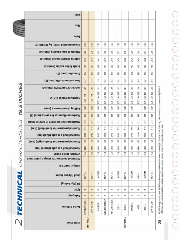
Te
ch
nic
al C
ha
ra
ct
er
ist
ics
19
.5 I
nc
he
s2 28Dimension
Tread Pattern
Category
Type
PR (Ply Rating)
Load / Speed Index
Norminal pressure for unique point (bar)
Original tread depth
Nominal load per axle (single) (kg)
Nominal pressure for load (single) (bar)
Nominal load per axle (dual) (kg)
Nominal pressure for load (dual) (bar)
Maximum section width in service (mm)
Maximum diameter in service (mm) (1)
Rolling circumference (mm)
Approved rim(s) ETRTO
Laden section width (mm) (2)
Free section width (mm) (2)
Diameter (mm) (2)
Static laden radius (mm) (2)
Rolling circumference (mm) (2)
Minimum dual spacing (mm) (2)
Recommended rim(s) by MICHELIN
Tube
Flap
Seal
Unique point (3)
26
9 24
7 85
5 39
7 26
10
280
6.75
26
8 24
6 85
7 39
7 26
10
278
6.75
28
7 25
9 86
4 40
1 26
42
293
7.50
29
6 26
2 87
0 39
3 26
15
300
7.50
29
6 26
2 87
0 39
3 26
15
300
7.50
28
7 26
3 87
0 40
2 26
50
297
7.50
28
3 26
3 87
2 40
5 26
60
298
7.50
28
5 26
2 86
8 40
2 26
38
296
7.50
28
6 26
5 87
0 40
3 26
50
300
7.50
26
2 26
2 87
5 40
4 26
60
297
7.50
28
8 26
4 87
5 40
5 26
70
299
7.50
XJS
WIN
TER
GRIP
+ 6
TL
13
6/13
4L
16.5
44
80
7.75
84
80
7.75
25
8 85
3 26
02
6.75
- 7.
50
XDW
ICE
GRIP
6
TL
13
6/13
4L
16.5
44
80
7.75
84
80
7.75
25
8 85
3 26
02
6.75
- 7.
50
X M
ULTI
Z
6 TL
14
14
0/13
8M
12.5
50
00
7.60
94
40
7.60
27
2 88
1 26
87
6.75 -
7.50
- 8.25
XZN+
MIX
ENE
RGY
6 TL
140/
138L
13
.0
5000
7.
75
9440
7.
75
272
881
2687
6.7
5 - 7.
50 - 8
.25
XZN
MIX
ENE
RGY
6 TL
140/
138L
13
.0
5000
7.
75
9440
7.
75
272
881
2687
6.7
5 - 7.
50 - 8
.25
XZE2
+ 6
TL
14
0/13
8M
13.6
50
00
7.75
94
40
7.75
27
2 88
1 26
87
6.75 -
7.50
- 8.25
26
5/70
R19.
5 XJ
W4+
6
TL
14
0/13
8L
15.0
50
00
7.75
94
40
7.75
27
2 88
1 26
87
6.75 -
7.50
- 8.25
X M
ULTI
D
6 TL
140/
138M
12
.5
5000
7.
60
9440
7.
60
272
881
2687
6.7
5 - 7.
50 - 8
.25
XTE2
2
TL
14
3/14
1J
14.0
54
50
8.50
10
300
8.60
27
2 88
1
6.75 -
7.50
- 8.25
XDE2
+ 6
TL
14
0/13
8M
16.0
50
00
7.75
94
40
7.75
27
2 88
1 26
87
6.75 -
7.50
- 8.25
XDW
ICE
GRIP
6
TL
14
0/13
8L
16.0
50
00
7.75
94
40
7.75
27
2 88
1 26
87
6.75 -
7.50
- 8.25
24
5/70
R19.
5
• (1)
ETRT
O ra
ting (
stand
ard v
alue,
the E
TRTO
stan
dard
rim
may b
e diff
erent
to th
e rim
reco
mmen
ded b
y MIC
HELIN
). • (
2) M
ICHE
LIN ra
ting,
value
mea
sured
on ri
m rec
omme
nded
by M
ICHE
LIN.
• (3)
Uniq
ue po
int: lo
ad ca
pacit
y/aut
horiz
ed ad
dition
al sp
eed p
air Lo
ad va
riatio
ns ac
cord
ing to
spee
d do n
ot ap
ply to
the u
nique
point
.

29
Tab
le o
f in
flat
ion
pre
ssu
re (
bar
) in
rel
atio
n t
o m
axim
um
load
per
axl
e (k
g)
Dimension
Tread pattern
sin
gle
dual
s
ingl
e
du
al
sin
gle
du
al
s
ingl
e
dual
sin
gle
du
al
s
ingl
e
dual
sin
gle
du
al
s
ingl
e
dual
sin
gle
du
al
s
ingl
e
dual
sin
gle
dual
2900
30
30
3160
32
90
3430
35
60
3690
38
20
3950
40
80
4220
43
50
4480
5490
57
40
5990
62
40
6480
67
30
6980
72
30
7480
77
30
7980
82
30
8480
2900
30
30
3160
32
90
3430
35
60
3690
38
20
3950
40
80
4220
43
50
4480
5490
57
40
5990
62
40
6480
67
30
6980
72
30
7480
77
30
7980
82
30
8480
3440
35
90
3740
38
90
4040
41
90
4340
44
90
4640
47
90
4940
6500
67
80
7070
73
50
7630
79
10
8200
84
80
8760
90
40
9330
32
40
3380
35
30
3680
38
20
3970
41
20
4260
44
10
4560
47
10
4850
50
00
6110
63
90
6660
69
40
7220
75
00
7770
80
50
8330
86
10
8880
91
60
9440
3240
33
80
3530
36
80
3820
39
70
4120
42
60
4410
45
60
4710
48
50
5000
6110
63
90
6660
69
40
7220
75
00
7770
80
50
8330
86
10
8880
91
60
9440
3230
33
80
3530
36
70
3820
39
70
4110
42
60
4410
45
50
4700
48
50
5000
6110
63
90
6660
69
40
7220
75
00
7770
80
50
8330
86
10
8880
91
60
9440
3230
33
80
3530
36
70
3820
39
70
4110
42
60
4410
45
50
4700
48
50
5000
6110
63
90
6660
69
40
7220
75
00
7770
80
50
8330
86
10
8880
91
60
9440
34
40
3590
37
40
3890
40
40
4190
43
40
4490
46
40
4790
49
40
65
00
6780
70
70
7350
76
30
7910
82
00
8480
87
60
9040
93
30
36
80
3830
39
80
4120
42
70
4420
45
70
4710
48
60
5010
51
60
5300
6960
72
40
7520
77
90
8070
83
50
8630
89
10
9190
94
60
9740
10
020
3230
33
80
3530
36
70
3820
39
70
4110
42
60
4410
45
50
4700
48
50
5000
6110
63
90
6660
69
40
7220
75
00
7770
80
50
8330
86
10
8880
91
60
9440
3230
33
80
3530
36
70
3820
39
70
4110
42
60
4410
45
50
4700
48
50
5000
6110
63
90
6660
69
40
7220
75
00
7770
80
50
8330
86
10
8880
91
60
9440
XJS
WIN
TER
GRIP
+
XDW
ICE
GRIP
X M
ULTI
Z
XZN+
MIX
ENER
GY
XZN
MIX
ENER
GY
XZE2
+
XJW
4+
X M
ULTI
D
XTE2
XDE2
+
XDW
ICE
GRIP
65
69
73
76
80
83
87
91
94
98
10
2 10
5 10
9 11
2 11
6
4.
50
4.75
5.
00
5.25
5.
50
5.75
6.
00
6.25
6.
50
6.75
7.
00
7.25
7.
50
7.75
8.
00
12
0 12
3 12
7 13
1
8.
25
8.50
8.
75
9.00
ps
i 36
40
44
47
51
54
58
62
ba
r 2.
50
2.75
3.
00
3.25
3.
50
3.75
4.
00
4.25
265
/70R
19.5
245/
70R1
9.5
Te
ch
nic
al
ch
ar
ac
te
ris
tic
s t
ab
le
a
nd
pr
od
uc
t o
ff
er

Te
ch
nic
al C
ha
ra
ct
er
ist
ics
19
.5 I
nc
he
s2 30
• (1)
ETRT
O ra
ting (
stand
ard v
alue,
the E
TRTO
stan
dard
rim
may b
e diff
erent
to th
e rim
reco
mmen
ded b
y MIC
HELIN
). • (
2) M
ICHE
LIN ra
ting,
value
mea
sured
on ri
m rec
omme
nded
by M
ICHE
LIN. •
(3) U
nique
point
: load
capa
city/a
utho
rized
addit
ional
spee
d pair
Load
varia
tions
acco
rding
to sp
eed d
o not
apply
to th
e uniq
ue po
int.
Dimension
Tread Pattern
Category
Type
PR (Ply Rating)
Load / Speed Index
Norminal pressure for unique point (bar)
Original tread depth
Nominal load per axle (single) (kg)
Nominal pressure for load (single) (bar)
Nominal load per axle (dual) (kg)
Nominal pressure for load (dual) (bar)
Maximum section width in service (mm)
Maximum diameter in service (mm) (1)
Rolling circumference (mm)
Approved rim(s) ETRTO
Laden section width (mm) (2)
Free section width (mm) (2)
Diameter (mm) (2)
Static laden radius (mm) (2)
Rolling circumference (mm) (2)
Minimum dual spacing (mm) (2)
Recommended rim(s) by MICHELIN
Tube
Flap
Seal
Unique point (3)
29
8 27
3 89
3 41
1 27
21
309
7.50
30
1 27
5 89
5 41
2 27
20
311
7.50
27
6 27
3 89
7 41
2 27
20
309
7.50
30
0 27
4 89
9 41
4 27
40
310
7.50
32
7 30
1 92
4 42
4 28
00
341
8.25
32
7 30
1 93
1 42
8 28
30
341
8.25
285/
70R1
9.5
X M
ULTI
Z
6 TL
146/
144L
14
5/14
3M 8
.30
12.5
60
00
8.30
11
200
8.30
29
4 91
1 27
79
7.50 -
8.25
- 9.00
XZE2
+ 6
TL
14
4/14
2M
145/
143L
8.0
0 13
.9
5600
8.
00
1060
0 8.
00
294
911
2779
7.5
0 - 8.
25 - 9
.00
X M
ULTI
D
6 TL
146/
144L
14
5/14
3M 8
.30
13.5
60
00
8.30
11
200
8.30
29
4 91
1 27
79
7.50 -
8.25
- 9.00
XDE2
+ 6
TL
14
4/14
2M
145/
143L
8.0
0 16
.5
5600
8.
00
1060
0 8.
00
294
911
2779
7.5
0 - 8.
25 - 9
.00
30
5/70
R19.
5 XZ
E2+
6 TL
147/
145M
14
8/14
6L 8
.00
14.9
61
50
8.00
11
600
8.00
30
9 94
1 28
70
8.25
- 9.
00
XDE2
+ 6
TL
14
7/14
5M
148/
146L
8.0
0 17
.5
6150
8.
00
1160
0 8.
00
309
949
2894
8.
25 -
9.00

31
Tab
le o
f in
flat
ion
pre
ssu
re (
bar
) in
rel
atio
n t
o m
axim
um
load
per
axl
e (k
g)
Dimension
Tread pattern
sin
gle
du
al
sin
gle
dual
s
ingl
e
du
al
singl
e
du
al s
ingl
e
du
al
sin
gle
dual
38
10
3980
41
40
4310
44
80
4640
48
10
4970
51
40
5300
54
70
5640
58
00
5970
71
20
7430
77
30
8040
83
50
8660
89
70
9280
95
90
9900
10
210
1052
0 10
830
1114
0
3680
38
40
4000
41
60
4320
44
80
4640
48
00
4960
51
20
5280
54
40
5600
6970
72
70
7570
78
70
8180
84
80
8780
90
90
9390
96
90
9990
10
300
1060
0
3810
39
80
4140
43
10
4480
46
40
4810
49
70
5140
53
00
5470
56
40
5800
59
70
7120
74
30
7730
80
40
8350
86
60
8970
92
80
9590
99
00
1021
0 10
520
1083
0 11
140
36
80
3840
40
00
4160
43
20
4480
46
40
4800
49
60
5120
52
80
5440
56
00
69
70
7270
75
70
7870
81
80
8480
87
80
9090
93
90
9690
99
90
1030
0 10
600
40
40
4220
43
90
4570
47
40
4920
51
00
5270
54
50
5620
58
00
5970
61
50
76
20
7950
82
90
8620
89
50
9280
96
10
9940
10
270
1061
0 10
940
1127
0 11
600
40
40
4220
43
90
4570
47
40
4920
51
00
5270
54
50
5620
58
00
5970
61
50
76
20
7950
82
90
8620
89
50
9280
96
10
9940
10
270
1061
0 10
940
1127
0 11
600
285/
70R1
9.5
X M
ULTI
Z
XZ
E2+
X M
ULTI
D
XD
E2+
305/
70R1
9.5
XZE2
+
XDE2
+
65
69
73
76
80
83
87
91
94
98
10
2 10
5 10
9 11
2 11
6
4.
50
4.75
5.
00
5.25
5.
50
5.75
6.
00
6.25
6.
50
6.75
7.
00
7.25
7.
50
7.75
8.
00
12
0 12
3 12
7 13
1
8.
25
8.50
8.
75
9.00
ps
i 36
40
44
47
51
54
58
62
ba
r 2.
50
2.75
3.
00
3.25
3.
50
3.75
4.
00
4.25
Te
ch
nic
al
ch
ar
ac
te
ris
tic
s t
ab
le
a
nd
pr
od
uc
t o
ff
er

Te
ch
nic
al C
ha
ra
ct
er
ist
ics
2
0-2
4 I
nc
he
s2 32
Dimension
Tread Pattern
Category
Type
PR (Ply Rating)
Load / Speed Index
Norminal pressure for unique point (bar)
Original tread depth
Nominal load per axle (single) (kg)
Nominal pressure for load (single) (bar)
Nominal load per axle (dual) (kg)
Nominal pressure for load (dual) (bar)
Maximum section width in service (mm)
Maximum diameter in service (mm) (1)
Rolling circumference (mm)
Approved rim(s) ETRTO
Laden section width (mm) (2)
Free section width (mm) (2)
Diameter (mm) (2)
Static laden radius (mm) (2)
Rolling circumference (mm) (2)
Minimum dual spacing (mm) (2)
Recommended rim(s) by MICHELIN
Tube
Flap
Unique point (3)
25
6 23
2 96
2 45
1 29
50
263
6.50
20
K
20x7
.50
283
256
1017
47
6.5
3115
29
0 7.
00
20 M
20
x7.5
0
30
7 27
7 10
49
489
3212
31
4 7.
50
20 N
20
x7.5
0
30
7 27
7 10
53
490
3211
31
4 7.
50
20 N
20
x7.5
0
30
9 27
7 10
57
495
31
3 7.
50
20 N
20
x7.5
0
31
1 28
0 10
60
494
3226
31
7 7.
50
20 N
20
x7.5
0
30
9 27
9 10
59
493
3240
31
6 7.
50
20 N
20
x7.5
0
31
0 28
1 10
64
497
3240
31
8 7.
50
20 N
20
x7.5
0
8.
25R2
0 XZ
E 6
TT
13
3/13
1K
133/
131L
6.5
0 11
.6
4120
6.
50
7800
6.
50
239
980
5.5
- B5.5
- 6.0
2989
6.0
0T - B
6.0 - 6
.5
B6.5
- 7.0
- B7.0
9.
00R2
0 XZ
E 2
2 TT
16
14
4/14
2K
13.7
56
00
9.00
10
600
9.00
6.0 - 6
.00T
6.
5 - 7
.0 -
7.5
10.0
0R20
XZ
E 3
R
2 TT
16
14
7/14
3K
12.5
61
50
8.00
10
900
8.00
28
6 10
74
3276
6.5
0 - 7.
00 - 7
.50
XZE
2 2
TT
16
147/
143K
14
6/14
3L 7
.75
13.8
61
50
8.00
10
900
8.00
28
6 10
74
3276
6.5
0 - 7.
00 - 7
.50
XZY3
HD
3 TT
16
14
7/14
3K
15.6
61
50
7.90
10
900
7.90
28
6 10
74
3276
6.5
0 - 7.
00
7.5
0 - 8.
00
XZY
3 3
TT
16
147/
143K
16
.6
6150
8.
00
1090
0 8.
00
286
1073
32
73
7.0
- 7.3
3
XDY3
HD
3 TT
16
14
7/14
3K
19.8
61
50
7.90
10
900
7.90
28
6 10
74
3276
6.
50 -
7.00
7.
50 -
8.00
XDY
3 3
TT
16
147/
143K
19
.8
6150
8.
00
1090
0 8.
00
286
1073
32
73
7.0 - 7
.33 - 7
.5 - 8
.0
Seal
• (1)
ETRT
O ra
ting (
stand
ard v
alue,
the E
TRTO
stan
dard
rim
may b
e diff
erent
to th
e rim
reco
mmen
ded b
y MIC
HELIN
). • (
2) M
ICHE
LIN ra
ting,
value
mea
sured
on ri
m rec
omme
nded
by M
ICHE
LIN. •
(3) U
nique
point
: load
capa
city/a
utho
rized
addit
ional
spee
d pair
Load
varia
tions
acco
rding
to sp
eed d
o not
apply
to th
e uniq
ue po
int.

33
Tab
le o
f in
flat
ion
pre
ssu
re (
bar
) in
rel
atio
n t
o m
axim
um
load
per
axl
e (k
g)
Dimension
Tread pattern
29
80
3130
32
70
3410
35
50
3690
38
40
3980
41
20
56
50
5920
61
90
6460
67
20
6990
72
60
7530
78
00
38
80
4020
41
60
4310
44
50
4590
47
40
4880
50
30
5170
53
10
5460
56
00
7340
76
10
7880
81
50
8430
87
00
8970
92
40
9510
97
80
1006
0 10
330
1060
0
4040
42
20
4390
45
70
4740
49
20
5100
52
70
5450
56
20
5800
59
70
6150
7160
74
70
7790
81
00
8410
87
20
9030
93
40
9650
99
70
1028
0 10
590
1090
0
40
40
4220
43
90
4570
47
40
4920
51
00
5270
54
50
5620
58
00
5970
61
50
71
60
7470
77
90
8100
84
10
8720
90
30
9340
96
50
9970
10
280
1059
0 10
900
4090
42
70
4440
46
20
4800
49
80
5150
53
30
5510
56
90
5870
60
40
7250
75
60
7880
81
90
8510
88
20
9140
94
50
9770
10
080
1040
0 10
710
4040
42
20
4390
45
70
4740
49
20
5100
52
70
5450
56
20
5800
59
70
6150
7160
74
70
7790
81
00
8410
87
20
9030
93
40
9650
99
70
1028
0 10
590
1090
0
40
90
4270
44
40
4620
48
00
4980
51
50
5330
55
10
5690
58
70
6040
72
50
7560
78
80
8190
85
10
8820
91
40
9450
97
70
1008
0 10
400
1071
0
40
40
4220
43
90
4570
47
40
4920
51
00
5270
54
50
5620
58
00
5970
61
50
71
60
7470
77
90
8100
84
10
8720
90
30
9340
96
50
9970
10
280
1059
0 10
900
8.2
5R20
XZ
E
9
.00R
20
16PR
10.0
0R20
XZ
E 3
R
XZE
2
XZY3
HD
XZY
3
XDY3
HD
XDY
3
65
69
73
76
80
83
87
91
94
98
10
2 10
5 10
9 11
2 11
6
4.
50
4.75
5.
00
5.25
5.
50
5.75
6.
00
6.25
6.
50
6.75
7.
00
7.25
7.
50
7.75
8.
00
12
0 12
3 12
7 13
1 13
4
8.2
5 8.
50
8.75
9.
00
9.25
ps
i 36
40
44
47
51
54
58
62
ba
r 2.
50
2.75
3.
00
3.25
3.
50
3.75
4.
00
4.25
sin
gle
2420
25
60
2700
28
40
du
al
45
70
4840
51
10
5380
sin
gle
dual
s
ingl
e
du
al
sin
gle
dual
s
ingl
e
du
al s
ingl
e
du
al
sin
gle
dual
sin
gle
dual
Te
ch
nic
al
ch
ar
ac
te
ris
tic
s t
ab
le
a
nd
pr
od
uc
t o
ff
er

Te
ch
nic
al C
ha
ra
ct
er
ist
ics
2
0-2
4 I
nc
he
s2 34
Dimension
Tread Pattern
Category
Type
PR (Ply Rating)
Load / Speed Index
Norminal pressure for unique point (bar)
Original tread depth
Nominal load per axle (single) (kg)
Nominal pressure for load (single) (bar)
Nominal load per axle (dual) (kg)
Nominal pressure for load (dual) (bar)
Maximum section width in service (mm)
Maximum diameter in service (mm) (1)
Rolling circumference (mm)
Approved rim(s) ETRTO
Laden section width (mm) (2)
Free section width (mm) (2)
Diameter (mm) (2)
Static laden radius (mm) (2)
Rolling circumference (mm) (2)
Minimum dual spacing (mm) (2)
Recommended rim(s) by MICHELIN
Tube
Flap
Unique point (3)
32
4 29
5 10
81
503
3311
33
4 8.
00
20 P
20
x8.5
0
30
7 27
7 10
53
490
3211
31
4 7.
50
20 N
20
x8.5
0
32
9 29
7 10
82
503
3303
33
6 8.
00
20 P
20
x8.5
0
33
0 29
8 10
90
506
3327
33
7 8.
00
20 P
20
x8.5
0
33
1 30
0 10
96
509
3329
34
0 8.
00
20 P
20
x8.5
0
345
313
1121
52
1 34
20
354
8.50
20
Q
20x8
.50
34
8 31
5 11
29
527
3451
35
7 8.
50
20 Q
20
x8.5
0
11.0
0R20
XZ
E 3
R 2
TT
16
150/
146K
15
0/14
7J
8.00
12
.3
6700
8.
00
1200
0 8.
00
297
1104
33
67
6.50
- 7.
0 - 7
.5
7.33
- 8.
0
XZ
E 2
2 TT
16
14
7/14
3K
13.8
61
50
8.00
10
900
8.00
28
6 10
74
3276
6.
50 -
7.0
- 7.5
7.
33 -
8.0
XZE
2 2
TT
16
150/
146K
14
.3
6700
8.
00
1200
0 8.
00
297
1104
33
67
7.33
V - 7
.5 -
8.0
8.
5 - B
8.5
- 9.0
XZY
3 3
TT
16
150/
146K
17
.5
6700
8.
00
1200
0 8.
00
297
1104
33
67
7.5
- 8.0
- 8.
0V
8.
5 - 8
.50V
XDY
3 3
TT
16
150/
146K
20
.8
6700
8.
00
1200
0 8.
00
297
1104
33
67
7.33 -
7.50
- 8.00
8.
50 -
9.00
12
.00R
20
XZE
2 2
TT
18
154/
150K
15
.2
7500
8.
50
1340
0 8.
50
319
1146
34
95
8.00
V - 8
.5
8.
50V
- 9.0
0V
XZY
3 3
TT
18
154/
150K
18
.1
7500
8.
50
1340
0 8.
50
319
1146
34
95
7.33
- 8.
00
Seal
• (1)
ETRT
O ra
ting (
stand
ard v
alue,
the E
TRTO
stan
dard
rim
may b
e diff
erent
to th
e rim
reco
mmen
ded b
y MIC
HELIN
). • (
2) M
ICHE
LIN ra
ting,
value
mea
sured
on ri
m rec
omme
nded
by M
ICHE
LIN. •
(3) U
nique
point
: load
capa
city/a
utho
rized
addit
ional
spee
d pair
Load
varia
tions
acco
rding
to sp
eed d
o not
apply
to th
e uniq
ue po
int.
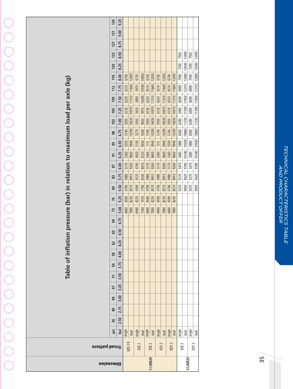
35
Tab
le o
f in
flat
ion
pre
ssu
re (
bar
) in
rel
atio
n t
o m
axim
um
load
per
axl
e (k
g)
Dimension
Tread pattern
sing
le
dua
l
sing
le
dua
l
sing
le
dua
l
sing
le
dua
l
sing
le
dua
l
sing
le
dua
l
sing
le
dua
l
44
00
4590
47
90
4980
51
70
5360
55
50
5740
59
30
6130
63
20
6510
67
00
78
90
8230
85
70
8910
92
60
9600
99
40
1029
0 10
630
1097
0 11
310
1166
0 12
000
4040
42
20
4390
45
70
4740
49
20
5100
52
70
5450
56
20
5800
59
70
6150
7160
74
70
7790
81
00
8410
87
20
9030
93
40
9650
99
70
1028
0 10
590
1090
0
44
00
4590
47
90
4980
51
70
5360
51
0 57
40
5930
61
30
6320
65
10
6700
7890
82
30
8570
89
10
9260
96
00
9940
10
290
1063
0 10
970
1131
0 11
660
1200
0
44
00
4590
47
90
4980
51
70
5360
51
0 57
40
5930
61
30
6320
65
10
6700
7890
82
30
8570
89
10
9260
96
00
9940
10
290
1063
0 10
970
1131
0 11
660
1200
0
44
00
4590
47
90
4980
51
70
5360
55
50
5740
59
30
6130
63
20
6510
67
00
78
90
8230
85
70
8910
92
60
9600
99
40
1029
0 10
630
1097
0 11
310
1166
0 12
000
5070
52
70
5470
56
80
5880
60
80
6280
64
90
6690
68
90
7090
73
00
7500
9050
94
20
9780
10
140
1050
0 10
860
1123
0 11
590
1195
0 12
310
1268
0 13
040
1340
0
50
70
5270
54
70
5680
58
80
6080
62
80
6490
66
90
6890
70
90
7300
75
00
90
50
9420
97
80
1014
0 10
500
1086
0 11
230
1159
0 11
950
1231
0 12
680
1304
0 13
400
11.0
0R20
XZ
E 3
R
XZE
2
XZ
E 2
XZY
3
XD
Y 3
12.
00R2
0 XZ
E 2
XZY
3
65
69
73
76
80
83
87
91
94
98
10
2 10
5 10
9 11
2 11
6
4.
50
4.75
5.
00
5.25
5.
50
5.75
6.
00
6.25
6.
50
6.75
7.
00
7.25
7.
50
7.75
8.
00
12
0 12
3 12
7 13
1 13
4
8.2
5 8.
50
8.75
9.
00
9.25
ps
i 36
40
44
47
51
54
58
62
ba
r 2.
50
2.75
3.
00
3.25
3.
50
3.75
4.
00
4.25
Te
ch
nic
al
ch
ar
ac
te
ris
tic
s t
ab
le
a
nd
pr
od
uc
t o
ff
er

Te
ch
nic
al C
ha
ra
ct
er
ist
ics
2
0-2
4 I
nc
he
s2 36
Dimension
Tread Pattern
Category
Type
PR (Ply Rating)
Load / Speed Index
Norminal pressure for unique point (bar)
Original tread depth
Nominal load per axle (single) (kg)
Nominal pressure for load (single) (bar)
Nominal load per axle (dual) (kg)
Nominal pressure for load (dual) (bar)
Maximum section width in service (mm)
Maximum diameter in service (mm) (1)
Rolling circumference (mm)
Approved rim(s) ETRTO
Laden section width (mm) (2)
Free section width (mm) (2)
Diameter (mm) (2)
Static laden radius (mm) (2)
Rolling circumference (mm) (2)
Minimum dual spacing (mm) (2)
Recommended rim(s) by MICHELIN
Tube
Flap
Unique point (3)
35
0 31
9 11
40
531
3468
36
0 8.
50
20
x8.5
0
35
1 31
8 11
35
529
3456
36
1 8.
50
20 Q
20
x8.5
0
34
7 31
1 12
23
566
3747
35
2 8.
50
24
/25x
8.50
34
8 31
4 12
30
570
3760
35
5 8.
50
24
/25x
8.50
12
.00R
20
XZH2
R
3 TL
154/
149G
15
6F
9.00
22
.0
7500
8.
50
1300
0 8.
50
319
1146
34
95
7.33V
- 8.0
- 8.0V
B8
.0 - 8
.5 - 8
.50V
B8
.5 - 9
.0 - 9
.00V
XDY
3 3
TT
18
154/
150K
21
.0
7500
8.
50
1340
0 8.
50
319
1158
35
32
7.33
- 8.
00
32
5/95
R24
X W
ORKS
XZ
3 TL
162/
160K
19
.0
9500
8.
50
1800
0 8.
50
327
1252
38
19
8.50
X W
ORKS
XD
3 TL
162/
160K
22
.0
9500
8.
50
1800
0 8.
50
327
1265
38
58
8.50
Seal
• (1)
ETRT
O ra
ting (
stand
ard v
alue,
the E
TRTO
stan
dard
rim
may b
e diff
erent
to th
e rim
reco
mmen
ded b
y MIC
HELIN
). • (
2) M
ICHE
LIN ra
ting,
value
mea
sured
on ri
m rec
omme
nded
by M
ICHE
LIN. •
(3) U
nique
point
: load
capa
city/a
utho
rized
addit
ional
spee
d pair
Load
varia
tions
acco
rding
to sp
eed d
o not
apply
to th
e uniq
ue po
int.

37
Tab
le o
f in
flat
ion
pre
ssu
re (
bar
) in
rel
atio
n t
o m
axim
um
load
per
axl
e (k
g)
Dimension
Tread pattern
sin
gle
dual
s
ingl
e
du
al
sin
gle
dual
s
ingl
e
du
al
4500
46
90
4880
50
70
5270
54
70
5680
58
80
6080
62
80
6490
66
90
6890
70
90
7300
75
00
7800
81
30
8450
87
80
9140
94
90
9840
10
190
1054
0 10
890
1124
0 11
590
1195
0 12
300
1265
0 13
000
5070
52
70
5470
56
80
5880
60
80
6280
64
90
6690
68
90
7090
73
00
7500
9050
94
20
9780
10
140
1050
0 10
860
1123
0 11
590
1195
0 12
310
1268
0 13
040
1340
0
69
30
7190
74
50
7700
79
60
8220
84
70
8730
89
90
9240
95
00
13
140
1362
0 14
110
1459
0 15
080
1557
0 16
050
1654
0 17
030
1751
0 18
000
6930
71
90
7450
77
00
7960
82
20
8470
87
30
8990
92
40
9500
1314
0 13
620
1411
0 14
590
1508
0 15
570
1605
0 16
540
1703
0 17
510
1800
0
XZH2
R 1
2.00
R20
XDY
3
325/
95R2
4 X
WOR
KS X
Z
X W
ORKS
XD
65
69
73
76
80
83
87
91
94
98
10
2 10
5 10
9 11
2 11
6
4.
50
4.75
5.
00
5.25
5.
50
5.75
6.
00
6.25
6.
50
6.75
7.
00
7.25
7.
50
7.75
8.
00
12
0 12
3 12
7 13
1 13
4
8.2
5 8.
50
8.75
9.
00
9.25
ps
i 36
40
44
47
51
54
58
62
ba
r 2.
50
2.75
3.
00
3.25
3.
50
3.75
4.
00
4.25
Te
ch
nic
al
ch
ar
ac
te
ris
tic
s t
ab
le
a
nd
pr
od
uc
t o
ff
er

Tech
nic
al C
ha
ra
ct
er
ist
ics
19
.5-2
2.5
In
ch
es
WID
EB
AS
E2 38
Dimension
Tread Pattern
Category
Type
PR (Ply Rating)
Load / Speed Index
Norminal pressure for unique point (bar)
Original tread depth
Nominal load per axle (single) (kg)
Nominal pressure for load (single) (bar)
Nominal load per axle (dual) (kg)
Nominal pressure for load (dual) (bar)
Maximum section width in service (mm)
Maximum diameter in service (mm) (1)
Rolling circumference (mm)
Approved rim(s) ETRTO
Laden section width (mm) (2)
Free section width (mm) (2)
Diameter (mm) (2)
Static laden radius (mm) (2)
Rolling circumference (mm) (2)
Minimum dual spacing (mm) (2)
Recommended rim(s) by MICHELIN
Tube
Flap
Unique point (3)
Seal
46
3 43
6 90
3 41
3 27
61
14
.00
464
434
1020
47
1
14
.00
464
435
1026
47
3
14
.00
46
4 43
5 10
04
465
14.0
0
458
433
1008
46
7
14
.00
47
4 44
2 10
71
495
3252
14.0
0
406
378
998
460
3068
11.7
5
410
381
1001
46
1 30
71
11
.75
40
3 37
6 99
6 45
8 30
60
11
.75
48
0 45
2 10
65
492
3245
14.0
0
480
452
1095
49
2 32
45
14
.00
497
1076
14.0
0
474
442
1071
49
5 32
52
14
.00
490
1058
14.0
0
445
/45R
19.5
XT
A2 E
NERG
Y 1
TL
16
0J
13.0
90
00
9.00
14.0
0
X
ONE
LINE
D 1
TL
20
LRL
19.2
92
50
8.25
46
3 10
36
14
.00
X ON
E LIN
E GR
IP D
2
TL
20
LRL
21.8
92
50
8.25
46
3 10
36
14
.00
X ON
E LIN
E EN
ERGY
T
1 TL
20
LR
L
10
.3
9250
8.
25
463
1036
14.0
0
X
ONE
MUL
TI E
NERG
Y T
2 TL
20
LR
L
12
.9
9250
8.
25
463
1036
14.0
0
XF
A2 E
NERG
Y 1
TL
15
8L
160J
9.
00
13.0
85
00
9.00
40
1 10
12
3087
11
.75
X M
ULTI
T
2 TL
160K
15
8L
8.50
13
.0
9000
9.
00
401
1012
30
87
11.7
5
X
MUL
TI T
2 2
TL
16
0K
158L
9.
00
14.9
45
00
9.00
40
1 10
12
3087
11
.75
- 12.
25
X
LINE
ENER
GY T
1
TL
16
0K
158L
9.
00
11.3
45
00
9.00
40
1 10
12
3087
11
.75
- 12.
25
X
ONE
XZY3
3
TL
LR
M
10.3
106
00
9.00
14.0
0
X
ONE
XZU
S 5
TL
LR
M
18.7
106
00
9.00
14.0
0
X
ONE
XDN2
2
TL
LR
L
21
.6 1
0000
9.
00
14
.00
X ON
E LIN
E GR
IP D
2
TL
20
164L
21
.8
1000
8.
30
470
1092
14.0
0
X
ONE
MUL
TI E
NERG
Y T
2 TL
LRL
12.8
100
00
9.00
14.0
0
• (1)
ETRT
O ra
ting (
stand
ard v
alue,
the E
TRTO
stan
dard
rim
may b
e diff
erent
to th
e rim
reco
mmen
ded b
y MIC
HELIN
). • (
2) M
ICHE
LIN ra
ting,
value
mea
sured
on ri
m rec
omme
nded
by M
ICHE
LIN. •
(3) U
nique
point
: load
capa
city/a
utho
rized
addit
ional
spee
d pair
Load
varia
tions
acco
rding
to sp
eed d
o not
apply
to th
e uniq
ue po
int.
385/
55R2
2.5
455/
55R2
2.5
445/
50R2
2.5

39
Tab
le o
f in
flat
ion
pre
ssu
re (
bar
) in
rel
atio
n t
o m
axim
um
load
per
axl
e (k
g)
Dimension
Tread pattern
sin
gle
s
ingl
e
sin
gle
s
ingl
e
sin
gle
s
ingl
e
sin
gle
s
ingl
e
sin
gle
s
ingl
e
sin
gle
s
ingl
e
sin
gle
s
ingl
e
62
30
6460
66
90
6920
71
50
7380
76
20
7850
80
80
8310
85
40
8770
90
00
63
00
6640
64
20
6699
69
78
7257
75
36
7816
82
40
8374
86
53
8932
92
50
63
00
6640
64
20
6699
69
78
7257
75
36
7816
82
40
8374
86
53
8932
92
50
6300
66
40
6420
66
99
6978
72
57
7536
78
16
8240
83
74
8653
89
32
9250
6300
66
40
6420
66
99
6978
72
57
7536
78
16
8240
83
74
8653
89
32
9250
62
30
6460
66
90
6920
71
50
7380
76
20
7850
80
80
8310
85
40
8770
90
00
6230
64
60
6690
69
20
7150
73
80
7620
78
50
8080
83
10
8540
87
70
9000
62
30
6460
66
90
6920
71
50
7380
76
20
7850
80
80
8310
85
40
8770
90
00
6230
64
60
6690
69
20
7150
73
80
7620
78
50
8080
83
10
8540
87
70
9000
76
26
7904
82
20
8497
86
53
8900
91
28
9433
97
01
1000
0 10
121
1041
9 10
600
76
26
7904
82
20
8497
86
53
8900
91
28
9433
97
01
1000
0 10
121
1041
9 10
600
6800
71
60
7462
76
97
7935
81
55
8469
86
88
8911
91
45
9450
96
63
1000
0
6800
71
60
7462
76
97
7935
81
55
8469
86
88
8911
91
45
9450
96
63
1000
0
68
00
7160
74
62
7697
79
35
8155
84
69
8688
89
11
9145
94
50
9663
10
000
445
/45R
19.5
XT
A2 E
NERG
Y
X
ONE
LINE
D
X
ONE
LINE
GRIP
D
X
ONE
LINE
ENER
GY T
X ON
E M
ULTI
ENE
RGY
T
XF
A2 E
NERG
Y
X
MUL
TI T
X M
ULTI
T2
X
LINE E
NERG
Y T
X ON
E XZ
Y3
X
ONE
XZU
S
X
ONE
XDN2
X ON
E LIN
E GR
IP D
X ON
E MUL
TI EN
ERGY
T
65
69
73
76
80
83
87
91
94
98
10
2 10
5 10
9 11
2 11
6
4.
50
4.75
5.
00
5.25
5.
50
5.75
6.
00
6.25
6.
50
6.75
7.
00
7.25
7.
50
7.75
8.
00
12
0 12
3 12
7 13
1
8.2
5 8.
50
8.75
9.
00
ps
i 36
40
44
47
51
54
58
62
ba
r 2.
50
2.75
3.
00
3.25
3.
50
3.75
4.
00
4.25
455/
55R2
2.5
385/
55R2
2.5
445/
50R2
2.5
Te
ch
nic
al
ch
ar
ac
te
ris
tic
s t
ab
le
a
nd
pr
od
uc
t o
ff
er

Tech
nic
al C
ha
ra
ct
er
ist
ics
19
.5-2
2.5
In
ch
es
WID
EB
AS
E2 40Dimension
Tread Pattern
Category
Type
PR (Ply Rating)
Load / Speed Index
Norminal pressure for unique point (bar)
Original tread depth
Nominal load per axle (single) (kg)
Nominal pressure for load (single) (bar)
Nominal load per axle (dual) (kg)
Nominal pressure for load (dual) (bar)
Maximum section width in service (mm)
Maximum diameter in service (mm) (1)
Rolling circumference (mm)
Approved rim(s) ETRTO
Laden section width (mm) (2)
Free section width (mm) (2)
Diameter (mm) (2)
Static laden radius (mm) (2)
Rolling circumference (mm) (2)
Minimum dual spacing (mm) (2)
Recommended rim(s) by MICHELIN
Tube
Flap
Unique point (3)
Seal
• (1)
ETRT
O ra
ting (
stand
ard v
alue,
the E
TRTO
stan
dard
rim
may b
e diff
erent
to th
e rim
reco
mmen
ded b
y MIC
HELIN
). • (
2) M
ICHE
LIN ra
ting,
value
mea
sured
on ri
m rec
omme
nded
by M
ICHE
LIN. •
(3) U
nique
point
: load
capa
city/a
utho
rized
addit
ional
spee
d pair
Load
varia
tions
acco
rding
to sp
eed d
o not
apply
to th
e uniq
ue po
int.
40
4 37
6 10
73
497
3288
11.7
5
405
376
1066
49
5 32
70
11
.75
40
4 37
9 10
72
499
3270
11.7
5
409
380
1074
49
8 32
74
11
.75
41
4 38
4 10
78
497
3309
11.7
5
409
379
1078
49
9 32
80
11
.75
40
6 37
7 10
66
494
3272
11.7
5
40
3 37
7 10
70
496
3286
11.7
5
407
376
1072
49
8 32
86
11
.75
40
7 37
8 10
74
497
3292
11.7
5
453
421
1136
52
3 34
60
13
.00
44
9 42
1 11
30
522
3440
13.0
0
486
451
1164
53
6 35
40
14
.00
48
1 45
1 11
58
534
3520
14.0
0
385/
65R2
2.5
X M
ULTI
F
2 TL
158L
16
0K
9.00
12
.5
8500
8.
50
405
1092
33
31
11.7
5
X
LINE
ENER
GY F
1 TL
160K
15
8L
9.00
12
.0
9000
9.
00
405
1092
33
31
11.7
5
XF
E 2
TL
16
0K
16.3
90
00
9.00
40
5 10
92
3331
11
.75
XFN
2 2
TL
15
8/L
160J
9.
00
15.4
85
00
8.50
40
5 11
03
3364
11
.75
- 12.
25
X
MUL
TIW
AY H
D XZ
E 2
TL
16
4K
15.3
10
000
9.00
40
5 11
03
3364
11
.75
XZY
3 3
TL
16
0K
158L
8.
50
17.7
90
00
9.00
40
5 10
92
3331
11
.75
- 12.
25
X
LINE
ENER
GY T
1
TL
16
0K
158L
8.
50
12.4
90
00
9.00
40
5 11
03
3364
11
.75
X M
ULTI
T
2 TL
160K
15
8L
8.50
15
.3
9000
9.
00
405
1103
33
64
11.7
5
X
ENER
GY S
AVER
GREE
N XT
1
TL
16
0J
158L
8.
50
16.0
90
00
9.00
38
9 10
72
3270
11
.75
XTE
3 2
TL
16
0J
158L
8.
50
17.3
90
00
9.00
38
9 10
92
3331
11
.75
425
/65R
22.5
XZ
Y 3
3 TL
20
16
5K
18.1
10
300
8.50
43
0 11
57
3529
13
.00
- 14.
00
XTE2
2
TL
20
165K
16
.3
1030
0 8.
50
447
1046
31
90
13.0
0 - 1
4.00
445
/65R
22.5
XZ
Y 3
3 TL
169K
18
.5
1160
0 9.
00
472
1174
35
81
14.0
0
XT
E2
2 TL
20
16
9K
16.8
11
600
9.00
47
2 11
74
3581
14
.00

41
Tab
le o
f in
flat
ion
pre
ssu
re (
bar
) in
rel
atio
n t
o m
axim
um
load
per
axl
e (k
g)
Dimension
Tread pattern
sin
gle
s
ingl
e
sin
gle
s
ingl
e
sin
gle
s
ingl
e
sin
gle
s
ingl
e
sin
gle
s
ingl
e
sin
gle
s
ingl
e
sin
gle
s
ingl
e
62
00
6430
66
60
6890
71
20
7350
75
80
7810
80
40
8270
85
00
6230
64
60
6690
69
20
7150
73
80
7620
78
50
8080
83
10
8540
87
70
9000
62
30
6460
66
90
6920
71
50
7380
76
20
7850
80
80
8310
85
40
8770
90
00
5740
59
70
6200
64
30
6660
68
90
7120
73
50
7580
78
10
8040
82
70
8500
69
20
7180
74
40
7690
79
50
8210
84
60
8720
89
70
9230
94
90
9740
10
000
62
30
6460
66
90
6920
71
50
7380
76
20
7850
80
80
8310
85
40
8770
90
00
6230
64
60
6690
69
20
7150
73
80
7620
78
50
8080
83
10
8540
87
70
9000
62
30
6460
66
90
6920
71
50
7380
76
20
7850
80
80
8310
85
40
8770
90
00
6230
64
60
6690
69
20
7150
73
80
7620
78
50
8080
83
10
8540
87
70
9000
62
30
6460
66
90
6920
71
50
7380
76
20
7850
80
80
8310
85
40
8770
90
00
7520
77
90
8070
83
50
8630
89
10
9190
94
60
9740
10
020
1030
0
69
60
7240
75
20
7790
80
70
8350
86
30
8910
91
90
9460
97
40
1002
0 10
300
8030
83
30
8630
89
20
9220
95
20
9820
10
110
1041
0 10
710
1101
0 11
300
1160
0
8030
83
30
8630
89
20
9220
95
20
9820
10
110
1041
0 10
710
1101
0 11
300
1160
0
385/
65R2
2.5
X M
ULTI
F
X
LINE
ENER
GY F
XFE
XFN
2
X
MUL
TIW
AY H
D XZ
E
XZ
Y 3
X LIN
E EN
ERGY
T
X
MUL
TI T
X EN
ERGY
SAVE
RGRE
EN X
T
XT
E 3
425/
65R2
2.5
XZY
3
XT
E2
445
/65R
22.5
XZ
Y 3
XTE2
65
69
73
76
80
83
87
91
94
98
10
2 10
5 10
9 11
2 11
6
4.
50
4.75
5.
00
5.25
5.
50
5.75
6.
00
6.25
6.
50
6.75
7.
00
7.25
7.
50
7.75
8.
00
12
0 12
3 12
7 13
1
8.2
5 8.
50
8.75
9.
00
ps
i 36
40
44
47
51
54
58
62
ba
r 2.
50
2.75
3.
00
3.25
3.
50
3.75
4.
00
4.25
Te
ch
nic
al
ch
ar
ac
te
ris
tic
s t
ab
le
a
nd
pr
od
uc
t o
ff
er

Tech
nic
al C
ha
ra
ct
er
ist
ics
2
2.5
In
ch
es
2 42Dimension
Tread Pattern
Category
Type
PR (Ply Rating)
Load / Speed Index
Norminal pressure for unique point (bar)
Original tread depth
Nominal load per axle (single) (kg)
Nominal pressure for load (single) (bar)
Nominal load per axle (dual) (kg)
Nominal pressure for load (dual) (bar)
Maximum section width in service (mm)
Maximum diameter in service (mm) (1)
Rolling circumference (mm)
Approved rim(s) ETRTO
Laden section width (mm) (2)
Free section width (mm) (2)
Diameter (mm) (2)
Static laden radius (mm) (2)
Rolling circumference (mm) (2)
Minimum dual spacing (mm) (2)
Recommended rim(s) by MICHELIN
Tube
Flap
Unique point (3)
Seal
24
5 22
2 96
5 45
0 29
50
251
6.00
24
6 21
9 96
9 45
0 29
60
248
6.00
27
0 24
5 10
14
473
3100
27
7 6.
75
27
1 24
4 10
17
473
3110
27
6 6.
75
30
2 28
1 10
48
492
3267
31
4 8.
25
29
9 27
2 10
44
488
3200
7.50
30
8 28
2 10
54
492
3221
32
0 8.
25
30
2 28
1 10
48
492
3267
31
4 8.
25
29
9 26
7 10
56
489
3228
30
2 7.
50
30
4 27
5 10
48
486
3198
31
1 7.
50
30
3 27
5 10
54
490
3220
31
1 7.
50
30
3 27
3 10
55
490
3225
30
9 7.
50
XZA
6 TL
133/
131L
13
.0
4120
6.
50
7800
6.
50
239
986
3007
6.
00 -
6.75
XZY
3 TL
133/
131K
13
.8
4120
6.
50
7800
6.
50
239
986
3007
6.
00 -
6.75
XZA
2 TL
144/
142L
15
.0
5600
8.
00
1060
0 8.
00
264
1038
31
66
6.75
- 7.
50
XZY
3 TL
144/
142K
13
.9
5600
8.
00
1060
0 8.
00
264
1038
31
66
6.75
- 7.
50
X M
ULTI
Z
2 TL
16
1
48/1
45L
13.8
63
00
8.00
11
600
8.00
29
0 10
70
3264
7.
50 -
8.25
X M
ULTI
Z2
2 TL
16
14
8/14
5L
14.5
63
00
8.50
11
600
8.50
29
0 10
70
3264
7.
50 -
8.25
X IN
CITY
Z
5 TL
16
14
8/14
5J
151/
148E
8.
30
16.0
63
00
8.30
11
600
8.30
29
0 10
70
3264
7.
50 -
8.25
X CO
ACH
ENER
GY Z
8
TL
14
8/14
5M
13.8
63
00
8.00
11
600
8.00
29
0 10
70
3264
7.
50 -
8.25
XZA
2+ E
NERG
Y 1
TL
14
8/14
5M
14.7
63
00
8.00
11
600
8.00
29
0 10
70
3264
7.
50 -
8.25
XJE4
MIX
ENE
RGY
1 TL
16
14
8/14
5L
14.3
63
00
8.00
11
600
8.00
27
9 10
37
3163
7.
50 -
8.25
XJW
4+
2 TL
16
14
8/14
5L
16.3
63
00
8.00
11
600
8.00
27
9 10
37
3163
7.
50 -
8.25
XZE2
+ 2
TL
16
148/
145L
15
.2
6300
8.
00
1160
0 8.
00
290
1070
32
64
7.50
- 8.
25
• (1)
ETRT
O ra
ting (
stand
ard v
alue,
the E
TRTO
stan
dard
rim
may b
e diff
erent
to th
e rim
reco
mmen
ded b
y MIC
HELIN
). • (
2) M
ICHE
LIN ra
ting,
value
mea
sured
on ri
m rec
omme
nded
by M
ICHE
LIN. •
(3) U
nique
point
: load
capa
city/a
utho
rized
addit
ional
spee
d pair
Load
varia
tions
acco
rding
to
spee
d do n
ot ap
ply to
the u
nique
point
.
9R22
.5
10R2
2.5
11R2
2.5

43
Tab
le o
f in
flat
ion
pre
ssu
re (
bar
) in
rel
atio
n t
o m
axim
um
load
per
axl
e (k
g)
Dimension
Tread pattern
XZA
XZY
XZA
XZY
X M
ULTI
Z
X M
ULTI
Z2
X IN
CITY
Z
X CO
ACH
ENER
GY Z
XZA
2+ E
NERG
Y
XJE4
MIX
ENE
RGY
XJW
4+
XZE2
+
29
80
3130
32
70
3410
35
50
3690
38
40
3980
41
20
5650
59
20
6190
64
60
6720
69
90
7260
75
30
7800
29
80
3130
32
70
3410
35
50
3690
38
40
3980
41
20
5650
59
20
6190
64
60
6720
69
90
7260
75
30
7800
36
80
3840
40
00
4160
43
20
4480
46
40
4800
49
60
5120
52
80
5440
56
00
6970
72
70
7570
78
70
8180
84
80
8780
90
90
9390
96
90
9990
10
300
1060
0
36
80
3840
40
00
4160
43
20
4480
46
40
4800
49
60
5120
52
80
5440
56
00
6970
72
70
7570
78
70
8180
84
80
8780
90
90
9390
96
90
9990
10
300
1060
0
41
40
4320
45
00
4680
48
60
5040
52
20
5400
55
80
5760
59
40
6120
63
00
7620
79
50
8290
86
20
8950
92
80
9610
99
40
1027
0 10
610
1094
0 11
270
1160
0
39
20
4070
42
30
4400
45
70
4750
49
20
5100
52
80
5460
56
20
5780
59
30
6110
63
00
7250
75
60
7870
81
80
8500
88
10
9120
94
30
9750
10
060
1036
0 10
670
1098
0 11
290
1160
0
41
80
4350
45
20
4700
48
70
5050
52
20
5400
55
70
5740
59
20
6090
62
70
7690
80
10
8330
86
50
8970
92
90
9610
99
30
1025
0 10
570
1090
0 11
220
1154
0
4140
43
20
4500
46
80
4860
50
40
5220
54
00
5580
57
60
5940
61
20
6300
76
20
7950
82
90
8620
89
50
9280
96
10
9940
10
270
1061
0 10
940
1127
0 11
600
4140
43
20
4500
46
80
4860
50
40
5220
54
00
5580
57
60
5940
61
20
6300
76
20
7950
82
90
8620
89
50
9280
96
10
9940
10
270
1061
0 10
940
1127
0 11
600
4140
43
20
4500
46
80
4860
50
40
5220
54
00
5580
57
60
5940
61
20
6300
76
20
7950
82
90
8620
89
50
9280
96
10
9940
10
270
1061
0 10
940
1127
0 11
600
4140
43
20
4500
46
80
4860
50
40
5220
54
00
5580
57
60
5940
61
20
6300
76
20
7950
82
90
8620
89
50
9280
96
10
9940
10
270
1061
0 10
940
1127
0 11
600
4140
43
20
4500
46
80
4860
50
40
5220
54
00
5580
57
60
5940
61
20
6300
76
20
7950
82
90
8620
89
50
9280
96
10
9940
10
270
1061
0 10
940
1127
0 11
600
sin
gle
2420
25
60
2700
28
40
dual
4570
48
40
5110
53
80 s
ingl
e
24
20
2560
27
00
2840
du
al
45
70
4840
51
10
5380
sin
gle
dual
s
ingl
e
du
al
sin
gle
dual
s
ingl
e
du
al
sin
gle
dual
s
ingl
e
du
al
sin
gle
dual
s
ingl
e
du
al
sin
gle
dual
s
ingl
e
du
al
65
69
73
76
80
83
87
91
94
98
10
2 10
5 10
9 11
2 11
6
4.
50
4.75
5.
00
5.25
5.
50
5.75
6.
00
6.25
6.
50
6.75
7.
00
7.25
7.
50
7.75
8.
00
12
0 12
3 12
7 13
1
8.2
5 8.
50
8.75
9.
00
ps
i 36
40
44
47
51
54
58
62
ba
r 2.
50
2.75
3.
00
3.25
3.
50
3.75
4.
00
4.25
9R22
.5
10R2
2.5
11R2
2.5
Te
ch
nic
al
ch
ar
ac
te
ris
tic
s t
ab
le
a
nd
pr
od
uc
t o
ff
er

Tech
nic
al C
ha
ra
ct
er
ist
ics
2
2.5
In
ch
es
2 44Dimension
Tread Pattern
Category
Type
PR (Ply Rating)
Load / Speed Index
Norminal pressure for unique point (bar)
Original tread depth
Nominal load per axle (single) (kg)
Nominal pressure for load (single) (bar)
Nominal load per axle (dual) (kg)
Nominal pressure for load (dual) (bar)
Maximum section width in service (mm)
Maximum diameter in service (mm) (1)
Rolling circumference (mm)
Approved rim(s) ETRTO
Laden section width (mm) (2)
Free section width (mm) (2)
Diameter (mm) (2)
Static laden radius (mm) (2)
Rolling circumference (mm) (2)
Minimum dual spacing (mm) (2)
Recommended rim(s) by MICHELIN
Tube
Flap
Unique point (3)
Seal
XZY
3 3
TL
16
148/
145K
19
.0
6300
8.
00
1160
0 8.
00
290
1070
32
64
7.5
0
XZY
2 3
TL
16
148/
145K
18
.2
6300
8.
00
1160
0 8.
00
290
1070
32
64
7.50
- 8.
25
XZU3
+ 5
TL
16
148/
145J
15
1/14
8E
8.00
19
.7
6300
8.
00
1160
0 8.
00
290
1070
32
64
7.50
- 8.
25
XJS
WIN
TER
GRIP
+ 2
TL
16
148/
145J
18
.9
6300
8.
00
1160
0 8.
00
290
1070
32
64
7.50
- 8.
25
X M
ULTI
D
2 TL
16
14
8/14
5L
21.5
63
00
8.00
11
600
8.00
29
0 10
70
3264
7.
50 -
8.25
X M
ULTI
D+
2
TL
16
148/
145L
23
.5
6300
8.
30
1160
0 8.
30
290
1070
32
64
7.50
- 8.
25
XDE
M/S
* 2
TL
16
LRH
28.0
60
00
8.25
10
900
8.25
29
0 10
70
3264
7.
50 -
8.25
XDY
3 3
TL
16
148/
145K
21
.5
6300
8.
00
1160
0 8.
00
290
1070
32
64
7.50
- 8.
25
XDW
ICE
GRIP
2
TL
16
19
.0
6300
8.
00
1160
0 8.
00
290
1070
32
64
7.50
- 8.
25
X M
ULTI
T
2 TL
16
14
8/14
5L
152/
148J
8.
30
13.5
63
00
8.30
11
600
8.30
29
0 10
70
3264
7.
50 -
8.25
XTE2
2
TL
14
142/
142J
13
.7
5300
8.
00
1060
0 8.
00
269
1064
32
45
7.50
- 8.
25
30
3 27
5 10
60
493
3236
31
1 7.
50
30
5 28
0 10
59
492
3230
31
6 7.
50
30
3 27
5 10
65
495
3227
31
1 7.
50
29
8 27
0 10
60
493
3240
30
5 7.
50
29
7 26
8 10
66
496
3234
30
3 7.
50
31
4 28
4 10
67
498
3233
32
1 8.
25
30
8 28
5
493
3238
31
8 8.2
5, 7.5
0
30
6 27
7 10
65
496
3250
31
4 7.
50
30
9 27
9 10
55
491
3220
31
5 7.
50
30
1 27
2 10
48
487
3206
30
8 8.
25
29
3 26
8 10
50
492
3216
30
3 7.
50
• (1)
ETRT
O ra
ting (
stand
ard v
alue,
the E
TRTO
stan
dard
rim
may b
e diff
erent
to th
e rim
reco
mmen
ded b
y MIC
HELIN
). • (
2) M
ICHE
LIN ra
ting,
value
mea
sured
on ri
m rec
omme
nded
by M
ICHE
LIN. •
(3) U
nique
point
: load
capa
city/a
utho
rized
addit
ional
spee
d pair
Load
varia
tions
acco
rding
to sp
eed d
o not
apply
to th
e uniq
ue po
int.
11
R22.
5

45
Tab
le o
f in
flat
ion
pre
ssu
re (
bar
) in
rel
atio
n t
o m
axim
um
load
per
axl
e (k
g)
Dimension
Tread pattern
sin
gle
dual
s
ingl
e
du
al
sin
gle
dual
s
ingl
e
du
al
sin
gle
dual
s
ingl
e
du
al
sin
gle
dual
s
ingl
e
du
al
sin
gle
dual
s
ingl
e
du
al
sin
gle
dual
41
40
4320
45
00
4680
48
60
5040
52
20
5400
55
80
5760
59
40
6120
63
00
7620
79
50
8290
86
20
8950
92
80
9610
99
40
1027
0 10
610
1094
0 11
270
1160
0
41
40
4320
45
00
4680
48
60
5040
52
20
5400
55
80
5760
59
40
6120
63
00
7620
79
50
8290
86
20
8950
92
80
9610
99
40
1027
0 10
610
1094
0 11
270
1160
0
41
40
4320
45
00
4680
48
60
5040
52
20
5400
55
80
5760
54
90
6120
63
00
7620
79
50
8290
86
20
8950
92
80
9610
99
40
1027
0 10
610
1094
0 11
270
1160
0
41
40
4320
45
00
4680
48
60
5040
52
20
5400
55
80
5760
54
90
6120
63
00
7620
79
50
8290
86
20
8950
92
80
9610
99
40
1027
0 10
610
1094
0 11
270
1160
0
41
40
4320
45
00
4680
48
60
5040
52
20
5400
55
80
5760
59
40
6120
63
00
7620
79
50
8290
86
20
8950
92
80
9610
99
40
1027
0 10
610
1094
0 11
270
1160
0
41
40
4320
45
00
4680
48
60
5040
52
20
5400
55
80
5760
59
40
6120
63
00
7620
79
50
8290
86
20
8950
92
80
9610
99
40
1027
0 10
610
1094
0 11
270
1160
0
4360
45
20
4650
48
40
5040
52
00
5320
54
80
5600
57
10
5790
59
00
6000
83
80
8640
88
50
9170
95
20
9840
10
080
1038
0 10
600
1069
0 10
760
1085
0 10
900
41
40
4320
45
00
4680
48
60
5040
52
20
5400
55
80
5760
59
40
6120
63
00
7620
79
50
8290
86
20
8950
92
80
9610
99
40
1027
0 10
610
1094
0 11
270
1160
0
41
40
4320
45
00
4680
48
60
5040
52
20
5400
55
80
5760
59
40
6120
63
00
7620
79
50
8290
86
20
8950
92
80
9610
99
40
1027
0 10
610
1094
0 11
270
1160
0
3820
40
10
4150
43
40
4480
47
00
4870
50
50
5220
54
00
5570
57
40
5920
60
90
6270
7050
74
10
7670
80
30
8290
86
50
8970
92
90
9610
99
30
1025
0 10
570
1090
0 11
220
1154
0
34
80
3630
37
90
3940
40
90
4240
43
90
4540
46
90
4850
50
00
5150
53
00
6970
72
70
7570
78
70
8180
84
80
8780
90
90
9390
96
90
9990
10
300
1060
0
XZY
3
XZY
2
XZU3
+
XJS
WIN
TER
GRIP
+
X M
ULTI
D
X M
ULTI
D+
XDE
M/S
*
XDY
3
XDW
ICE
GRIP
X M
ULTI
T
XTE2
65
69
73
76
80
83
87
91
94
98
10
2 10
5 10
9 11
2 11
6
4.
50
4.75
5.
00
5.25
5.
50
5.75
6.
00
6.25
6.
50
6.75
7.
00
7.25
7.
50
7.75
8.
00
12
0 12
3 12
7 13
1
8.2
5 8.
50
8.75
9.
00
ps
i 36
40
44
47
51
54
58
62
ba
r 2.
50
2.75
3.
00
3.25
3.
50
3.75
4.
00
4.25
11R2
2.5
Te
ch
nic
al
ch
ar
ac
te
ris
tic
s t
ab
le
a
nd
pr
od
uc
t o
ff
er
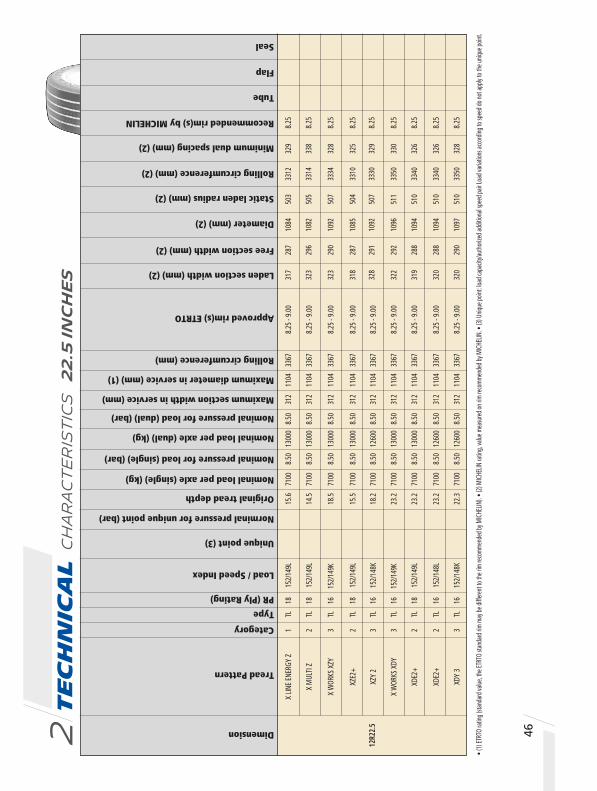
Tech
nic
al C
ha
ra
ct
er
ist
ics
2
2.5
In
ch
es
2 46Dimension
Tread Pattern
Category
Type
PR (Ply Rating)
Load / Speed Index
Norminal pressure for unique point (bar)
Original tread depth
Nominal load per axle (single) (kg)
Nominal pressure for load (single) (bar)
Nominal load per axle (dual) (kg)
Nominal pressure for load (dual) (bar)
Maximum section width in service (mm)
Maximum diameter in service (mm) (1)
Rolling circumference (mm)
Approved rim(s) ETRTO
Laden section width (mm) (2)
Free section width (mm) (2)
Diameter (mm) (2)
Static laden radius (mm) (2)
Rolling circumference (mm) (2)
Minimum dual spacing (mm) (2)
Recommended rim(s) by MICHELIN
Tube
Flap
Unique point (3)
Seal
31
7 28
7 10
84
503
3312
32
9 8.
25
32
3 29
6 10
82
505
3314
33
8 8.
25
32
3 29
0 10
92
507
3334
32
8 8.
25
31
8 28
7 10
85
504
3310
32
5 8.
25
32
8 29
1 10
92
507
3330
32
9 8.
25
32
2 29
2 10
96
511
3350
33
0 8.
25
31
9 28
8 10
94
510
3340
32
6 8.
25
32
0 28
8 10
94
510
3340
32
6 8.
25
32
0 29
0 10
97
510
3350
32
8 8.
25
12R2
2.5
X LIN
E EN
ERGY
Z
1 TL
18
15
2/14
9L
15.6
71
00
8.50
13
000
8.50
31
2 11
04
3367
8.
25 -
9.00
X M
ULTI
Z
2 TL
18
15
2/14
9L
14.5
71
00
8.50
13
000
8.50
31
2 11
04
3367
8.
25 -
9.00
X W
ORKS
XZY
3
TL
16
152/
149K
18
.5
7100
8.
50
1300
0 8.
50
312
1104
33
67
8.25
- 9.
00
XZE2
+ 2
TL
18
152/
149L
15
.5
7100
8.
50
1300
0 8.
50
312
1104
33
67
8.25
- 9.
00
XZY
2 3
TL
16
152/
148K
18
.2
7100
8.
50
1260
0 8.
50
312
1104
33
67
8.25
- 9.
00
X
WOR
KS X
DY
3 TL
16
15
2/14
9K
23.2
71
00
8.50
13
000
8.50
31
2 11
04
3367
8.
25 -
9.00
XDE2
+ 2
TL
18
152/
149L
23
.2
7100
8.
50
1300
0 8.
50
312
1104
33
67
8.25
- 9.
00
XDE2
+ 2
TL
16
152/
148L
23
.2
7100
8.
50
1260
0 8.
50
312
1104
33
67
8.25
- 9.
00
XD
Y 3
3 TL
16
15
2/14
8K
22.3
71
00
8.50
12
600
8.50
31
2 11
04
3367
8.
25 -
9.00
• (1)
ETRT
O ra
ting (
stand
ard v
alue,
the E
TRTO
stan
dard
rim
may b
e diff
erent
to th
e rim
reco
mmen
ded b
y MIC
HELIN
). • (
2) M
ICHE
LIN ra
ting,
value
mea
sured
on ri
m rec
omme
nded
by M
ICHE
LIN. •
(3) U
nique
point
: load
capa
city/a
utho
rized
addit
ional
spee
d pair
Load
varia
tions
acco
rding
to sp
eed d
o not
apply
to th
e uniq
ue po
int.

47
Tab
le o
f in
flat
ion
pre
ssu
re (
bar
) in
rel
atio
n t
o m
axim
um
load
per
axl
e (k
g)
Dimension
Tread pattern
12R2
2.5
X LIN
E EN
ERGY
Z
X M
ULTI
Z
X W
ORKS
XZY
XZE2
+
XZY
2
X
WOR
KS X
DY
XDE2
+
XDE2
+
XD
Y 3
48
00
4990
51
80
5370
55
60
5760
59
50
6140
63
30
6520
67
20
6910
71
00
8780
91
40
9490
98
40
1019
0 10
540
1089
0 11
240
1159
0 11
950
1230
0 12
650
1300
0
48
00
4990
51
80
5370
55
60
5760
59
50
6140
63
30
6520
67
20
6910
71
00
8780
91
40
9490
98
40
1019
0 10
540
1089
0 11
240
1159
0 11
950
1230
0 12
650
1300
0
48
00
4990
51
80
5370
55
60
5760
59
50
6140
63
30
6520
67
20
6910
71
00
8780
91
40
9490
98
40
1019
0 10
540
1089
0 11
240
1159
0 11
950
1230
0 12
650
1300
0
4800
49
90
5180
53
70
5560
57
60
5950
61
40
6330
65
20
6720
69
10
7100
87
80
9140
94
90
9840
10
190
1054
0 10
890
1124
0 11
590
1195
0 12
300
1265
0 13
000
4800
49
90
5180
53
70
5560
57
60
5950
61
40
6330
65
20
6720
69
10
7100
85
10
8850
91
90
9540
98
80
1022
0 10
560
1090
0 11
240
1158
0 11
920
1226
0 12
600
4800
49
90
5180
53
70
5560
57
60
5950
61
40
6330
65
20
6720
69
10
7100
87
80
9140
94
90
9840
10
190
1054
0 10
890
1124
0 11
590
1195
0 12
300
1265
0 13
000
4800
49
90
5180
53
70
5560
57
60
5950
61
40
6330
65
20
6720
69
10
7100
87
80
9140
94
90
9840
10
190
1054
0 10
890
1124
0 11
590
1195
0 12
300
1265
0 13
000
4800
49
90
5180
53
70
5560
57
60
5950
61
40
6330
65
20
6720
69
10
7100
85
10
8850
91
90
9540
98
80
1022
0 10
560
1090
0 11
240
1158
0 11
920
1226
0 12
600
4800
49
90
5180
53
70
5560
57
60
5950
61
40
6330
65
20
6720
69
10
7100
85
10
8850
91
90
9540
98
80
1022
0 10
560
1090
0 11
240
1158
0 11
920
1226
0 12
600
sin
gle
du
al
s
ingl
e
dual
sin
gle
du
al
s
ingl
e
dual
sin
gle
du
al
s
ingl
e
dual
sin
gle
du
al
s
ingl
e
dual
sin
gle
du
al
65
69
73
76
80
83
87
91
94
98
10
2 10
5 10
9 11
2 11
6
4.
50
4.75
5.
00
5.25
5.
50
5.75
6.
00
6.25
6.
50
6.75
7.
00
7.25
7.
50
7.75
8.
00
12
0 12
3 12
7 13
1
8.2
5 8.
50
8.75
9.
00
ps
i 36
40
44
47
51
54
58
62
ba
r 2.
50
2.75
3.
00
3.25
3.
50
3.75
4.
00
4.25
Te
ch
nic
al
ch
ar
ac
te
ris
tic
s t
ab
le
a
nd
pr
od
uc
t o
ff
er
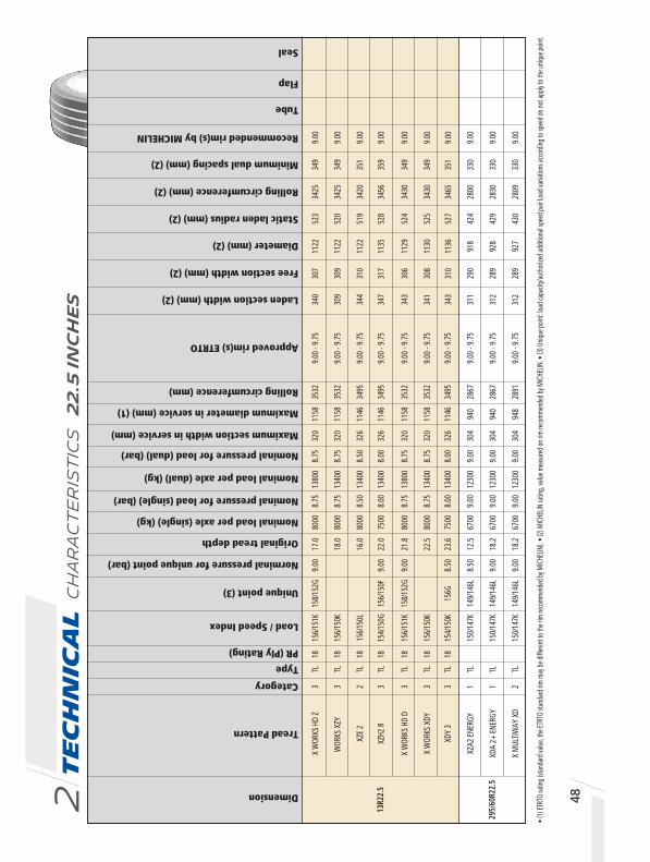
Tech
nic
al C
ha
ra
ct
er
ist
ics
2
2.5
In
ch
es
2 48
Dimension
Tread Pattern
Category
Type
PR (Ply Rating)
Load / Speed Index
Norminal pressure for unique point (bar)
Original tread depth
Nominal load per axle (single) (kg)
Nominal pressure for load (single) (bar)
Nominal load per axle (dual) (kg)
Nominal pressure for load (dual) (bar)
Maximum section width in service (mm)
Maximum diameter in service (mm) (1)
Rolling circumference (mm)
Approved rim(s) ETRTO
Laden section width (mm) (2)
Free section width (mm) (2)
Diameter (mm) (2)
Static laden radius (mm) (2)
Rolling circumference (mm) (2)
Minimum dual spacing (mm) (2)
Recommended rim(s) by MICHELIN
Tube
Flap
Unique point (3)
Seal
• (1)
ETRT
O ra
ting (
stand
ard v
alue,
the E
TRTO
stan
dard
rim
may b
e diff
erent
to th
e rim
reco
mmen
ded b
y MIC
HELIN
). • (
2) M
ICHE
LIN ra
ting,
value
mea
sured
on ri
m rec
omme
nded
by M
ICHE
LIN. •
(3) U
nique
point
: load
capa
city/a
utho
rized
addit
ional
spee
d pair
Load
varia
tions
acco
rding
to sp
eed d
o not
apply
to th
e uniq
ue po
int.
34
0 30
7 11
22
523
3425
34
9 9.
00
30
9 30
9 11
22
520
3425
34
9 9.
00
344
310
1122
51
9 34
20
351
9.00
34
7 31
7 11
35
528
3456
35
9 9.
00
34
3 30
6 11
29
524
3430
34
9 9.
00
34
1 30
8 11
30
525
3430
34
9 9.
00
343
310
1136
52
7 34
65
351
9.00
31
1 29
0 91
8 42
4 28
00
330
9.00
312
289
928
429
2830
33
0 9.
00
312
289
927
430
2809
33
0 9.
00
13R2
2.5
X W
ORKS
HD
Z 3
TL
18
156/
151K
15
8/15
2G
9.00
17
.0
8000
8.
75
1380
0 8.
75
320
1158
35
32
9.00
- 9.
75
W
ORKS
XZY
3
TL
18
156/
150K
18
.0
8000
8.
75
1340
0 8.
75
320
1158
35
32
9.00
- 9.
75
XZE
2 2
TL
18
156/
150L
16
.0
8000
8.
50
1340
0 8.
50
326
1146
34
95
9.00
- 9.
75
XZH2
R
3 TL
18
15
4/15
0G
156/
150F
9.
00
22.0
75
00
8.00
13
400
8.00
32
6 11
46
3495
9.
00 -
9.75
X W
ORKS
HD
D 3
TL
18
156/
151K
15
8/15
2G
9.00
21
.8
8000
8.
75
1380
0 8.
75
320
1158
35
32
9.00
- 9.
75
X W
ORKS
XDY
3
TL
18
156/
150K
22
.5
8000
8.
75
1340
0 8.
75
320
1158
35
32
9.00
- 9.
75
XDY
3 3
TL
18
154/
150K
15
6G
8.50
23
.6
7500
8.
00
1340
0 8.
00
326
1146
34
95
9.00
- 9.
75
295/
60R2
2.5
XZA2
ENE
RGY
1 TL
150/
147K
14
9/14
6L
8.50
12
.5
6700
9.
00
1230
0 9.
00
304
940
2867
9.
00 -
9.75
XDA
2+ E
NERG
Y 1
TL
15
0/14
7K
149/
146L
9.
00
18.2
67
00
9.00
12
300
9.00
30
4 94
0 28
67
9.00
- 9.
75
X
MUL
TIW
AY X
D 2
TL
15
0/14
7K
149/
146L
9.
00
18.2
67
00
9.00
12
300
9.00
30
4 94
8 28
91
9.00
- 9.
75

49
Tab
le o
f in
flat
ion
pre
ssu
re (
bar
) in
rel
atio
n t
o m
axim
um
load
per
axl
e (k
g)
Dimension
Tread pattern
56
80
5890
61
10
6320
65
30
6740
69
50
7160
73
70
7580
77
90
8000
9810
10
170
1053
0 10
890
1126
0 11
620
1198
0 12
350
1271
0 13
070
1344
0 13
800
56
80
5890
61
10
6320
65
30
6740
69
50
7160
73
70
7580
77
90
8000
9520
98
70
1023
0 10
580
1093
0 11
280
1164
0 11
990
1234
0 12
690
1305
0 13
400
62
70
6485
67
00
6920
71
40
7350
75
70
7780
80
00
1050
0 10
865
1123
0 11
590
1195
0 12
310
1268
0 13
040
1340
0
49
30
5140
53
60
5570
57
90
6000
62
10
6430
66
40
6860
70
70
7290
75
00
8810
91
90
9570
99
50
1034
0 10
720
1110
0 11
490
1187
0 12
250
1263
0 13
020
1340
0
56
80
5890
61
10
6320
65
30
6740
69
50
7160
73
70
7580
77
90
8000
9810
10
170
1053
0 10
890
1126
0 11
620
1198
0 12
350
1271
0 13
070
1344
0 13
800
56
80
5890
61
10
6320
65
30
6740
69
50
7160
73
70
7580
77
90
8000
9520
98
70
1023
0 10
580
1093
0 11
280
1164
0 11
990
1234
0 12
690
1305
0 13
400
49
30
5140
53
60
5570
57
90
6000
62
10
6430
66
40
6860
70
70
7290
75
00
8810
91
90
9570
99
50
1034
0 10
720
1110
0 11
490
1187
0 12
250
1263
0 13
020
1340
0
46
40
4810
49
80
5150
53
30
5500
56
70
5840
60
10
6180
63
60
6530
67
00
8520
88
30
9150
94
60
9780
10
090
1041
0 10
720
1104
0 11
350
1167
0 11
980
1230
0
4640
48
10
4980
51
50
5330
55
00
5670
58
40
6010
61
80
6360
65
30
6700
85
20
8830
91
50
9460
97
80
1009
0 10
410
1072
0 11
040
1135
0 11
670
1198
0 12
300
46
40
4810
49
80
5150
53
30
5500
56
70
5840
60
10
6180
63
60
6530
67
00
8520
88
30
9150
64
60
9780
10
090
1041
0 10
720
1104
0 11
350
1167
0 11
980
1230
0
sin
gle
dual
s
ingl
e
du
al
sin
gle
dual
s
ingl
e
du
al
sin
gle
dual
s
ingl
e
du
al
sin
gle
dual
s
ingl
e
du
al
sin
gle
dual
s
ingl
e
du
al
13R2
2.5
X W
ORKS
HD
Z
WOR
KS X
ZY
XZE
2
XZH2
R
X W
ORKS
HD
D
X W
ORKS
XDY
XDY
3
29
5/60
R22.
5 XZ
A2 E
NERG
Y
XDA
2+ E
NERG
Y
X M
ULTI
WAY
XD
65
69
73
76
80
83
87
91
94
98
10
2 10
5 10
9 11
2 11
6
4.
50
4.75
5.
00
5.25
5.
50
5.75
6.
00
6.25
6.
50
6.75
7.
00
7.25
7.
50
7.75
8.
00
12
0 12
3 12
7 13
1
8.2
5 8.
50
8.75
9.
00
ps
i 36
40
44
47
51
54
58
62
ba
r 2.
50
2.75
3.
00
3.25
3.
50
3.75
4.
00
4.25
Te
ch
nic
al
ch
ar
ac
te
ris
tic
s t
ab
le
a
nd
pr
od
uc
t o
ff
er

Tech
nic
al C
ha
ra
ct
er
ist
ics
2
2.5
In
ch
es
2 50
Dimension
Tread Pattern
Category
Type
PR (Ply Rating)
Load / Speed Index
Norminal pressure for unique point (bar)
Original tread depth
Nominal load per axle (single) (kg)
Nominal pressure for load (single) (bar)
Nominal load per axle (dual) (kg)
Nominal pressure for load (dual) (bar)
Maximum section width in service (mm)
Maximum diameter in service (mm) (1)
Rolling circumference (mm)
Approved rim(s) ETRTO
Laden section width (mm) (2)
Free section width (mm) (2)
Diameter (mm) (2)
Static laden radius (mm) (2)
Rolling circumference (mm) (2)
Minimum dual spacing (mm) (2)
Recommended rim(s) by MICHELIN
Tube
Flap
Unique point (3)
Seal
33
5 31
4 95
2 44
1 29
00
350
9.00
33
7 31
3 96
4 44
7 29
40
350
9.00
27
1 24
8 93
0 43
3 28
41
281
6.75
28
0 26
0 93
2 43
7 28
56
295
7.50
30
2 27
8 95
9 44
8 29
42
311
7.50
29
9 27
6 96
2 44
8 29
33
303
7.50
29
9 27
6 96
6 44
8 29
50
312
7.50
29
8 27
6 96
9 45
0 29
60
312
7.50
29
8 27
4 95
8 44
6 29
29
310
7.50
29
9 27
5 97
3 45
4 29
70
311
7.50
• (1)
ETRT
O ra
ting (
stand
ard v
alue,
the E
TRTO
stan
dard
rim
may b
e diff
erent
to th
e rim
reco
mmen
ded b
y MIC
HELIN
). • (
2) M
ICHE
LIN ra
ting,
value
mea
sured
on ri
m rec
omme
nded
by M
ICHE
LIN. •
(3) U
nique
point
: load
capa
city/a
utho
rized
addit
ional
spee
d pair
Load
varia
tions
acco
rding
to sp
eed d
o not
apply
to th
e uniq
ue po
int.
315
/60R
22.5
XZ
A2 E
NERG
Y 1
TL
15
2/14
8L
12.5
71
00
9.00
12
600
8.50
32
6 96
6 29
46
9.00
- 9.
75
XD
A 2+
ENE
RGY
1 TL
152/
148L
19
.0
7100
9.
00
1260
0 8.
50
326
966
2946
9.
00 -
9.75
255/
70R2
2.5
XZA
1 TL
140/
137M
14
0L
8.50
13
.0
5000
8.
00
9200
8.
00
265
944
2879
6.
75 -
7.50
- 8.
25
XZE*
2
TL
LR
H
14
.3
5000
8.
25
9200
8.
25
265
944
2879
6.
75 -
7.50
- 8.
25
275/
70R2
2.5
X M
ULTI
Z
2 TL
18
14
8/14
5L
149/
146K
9.
00
14.0
63
00
9.00
11
600
9.00
28
7 97
4 29
71
7.50
- 8.
25
X
INCI
TY Z
5
TL
18
148/
145J
15
2/14
8E
16
.0
6300
9.
00
1160
0 9.
00
287
974
2971
7.
50 -
8.25
XZE2
+ 2
TL
18
148/
145M
15
.0
6300
9.
00
1160
0 9.
00
287
974
2971
7.
50 -
8.25
XJW
4+
2 TL
148/
145L
16
.3
6300
9.
00
1160
0 8.
50
287
974
2971
7.
50 -
8.25
- 9.
00
X
MUL
TI D
2
TL
18
148/
145L
14
9/14
6K
9.00
15
.0
6300
9.
00
1160
0 9.
00
287
974
2971
7.
50 -
8.25
XDE2
+ 2
TL
16
148/
145M
18
.5
6300
9.
00
1160
0 9.
00
287
974
2971
7.
50 -
8.25

51
Tab
le o
f in
flat
ion
pre
ssu
re (
bar
) in
rel
atio
n t
o m
axim
um
load
per
axl
e (k
g)
Dimension
Tread pattern
49
20
5100
52
80
5460
56
40
5830
60
10
6190
63
70
6550
67
40
6920
71
00
9190
95
40
9880
10
220
1056
0 10
900
1124
0 11
580
1192
0 12
260
1260
0
49
20
5100
52
80
5460
56
40
5830
60
10
6190
63
70
6550
67
40
6920
71
00
9190
95
40
9880
10
220
1056
0 10
900
1124
0 11
580
1192
0 12
260
1260
0
32
90
3430
35
70
3710
38
60
4000
41
40
4290
44
30
4570
47
10
4860
50
00
6050
63
10
6570
68
30
7100
73
60
7620
78
90
8150
84
10
8670
89
40
9200
38
00
3910
40
20
4130
42
40
4360
44
80
4600
47
00
4800
49
00
5000
7200
74
00
7600
78
00
8000
81
20
8240
83
60
8570
87
80
8990
92
00
43
60
4520
46
80
4850
50
10
5170
53
30
5490
56
50
5820
59
80
6140
63
00
8030
83
30
8630
89
20
9220
95
20
9820
10
110
1041
0 10
710
1101
0 11
300
1160
0
4360
45
20
4680
48
50
5010
51
70
5330
54
90
5650
58
20
5980
61
40
6300
80
30
8330
86
30
8920
92
20
9520
98
20
1011
0 10
410
1071
0 11
010
1130
0 11
600
4360
45
20
4680
48
50
5010
51
70
5330
54
90
5650
58
20
5980
61
40
6300
80
30
8330
86
30
8920
92
20
9520
98
20
1011
0 10
410
1071
0 11
010
1130
0 11
600
43
60
4520
46
80
4850
50
10
5170
53
30
5490
56
50
5820
59
80
6140
63
00
8030
83
30
8630
89
20
9220
95
20
9820
10
110
1041
0 10
710
1101
0 11
300
1160
0
sin
gle
dual
s
ingl
e
du
al
sin
gle
dual
s
ingl
e
du
al
sin
gle
dual
s
ingl
e
du
al
sin
gle
dual
s
ingl
e
du
al
sin
gle
dual
s
ingl
e
du
al
315/
60R2
2.5
XZA2
ENE
RGY
XDA
2+ E
NERG
Y
255/
70R2
2.5
XZA
XZE*
275/
70R2
2.5
X M
ULTI
Z
X
INCI
TY Z
XZE2
+
XJW
4+
X M
ULTI
D
XDE2
+
65
69
73
76
80
83
87
91
94
98
10
2 10
5 10
9 11
2 11
6
4.
50
4.75
5.
00
5.25
5.
50
5.75
6.
00
6.25
6.
50
6.75
7.
00
7.25
7.
50
7.75
8.
00
12
0 12
3 12
7 13
1
8.2
5 8.
50
8.75
9.
00
ps
i 36
40
44
47
51
54
58
62
ba
r 2.
50
2.75
3.
00
3.25
3.
50
3.75
4.
00
4.25
Te
ch
nic
al
ch
ar
ac
te
ris
tic
s t
ab
le
a
nd
pr
od
uc
t o
ff
er

Tech
nic
al C
ha
ra
ct
er
ist
ics
2
2.5
In
ch
es
2 52
Dimension
Tread Pattern
Category
Type
PR (Ply Rating)
Load / Speed Index
Norminal pressure for unique point (bar)
Original tread depth
Nominal load per axle (single) (kg)
Nominal pressure for load (single) (bar)
Nominal load per axle (dual) (kg)
Nominal pressure for load (dual) (bar)
Maximum section width in service (mm)
Maximum diameter in service (mm) (1)
Rolling circumference (mm)
Approved rim(s) ETRTO
Laden section width (mm) (2)
Free section width (mm) (2)
Diameter (mm) (2)
Static laden radius (mm) (2)
Minimum dual spacing (mm) (2)
Rolling circumference (mm) (2)
Recommended rim(s) by MICHELIN
Tube
Flap
Unique point (3)
Seal
29
9 27
6 97
0 45
2 29
70
311
7.50
30
3 28
0 96
0 44
7 29
43
311
7.50
29
8 27
1 95
4 44
0 29
24
307
7.50
29
8 27
6 97
0 45
0 29
60
312
7.50
32
8 30
8 99
8 46
2 30
48
340
8.25
33
3 30
8 10
10
471
3093
34
0 8.
25
10
03
468
34
1 8.
25
32
3 29
6 10
08
466
3070
34
0 8.
25
32
4 30
0 99
5 46
0 30
30
339
8.25
32
7 30
2 10
03
465
3060
34
2 8.
25
32
5 29
9 10
02
466
3064
34
0 8.
25
32
5 30
1 10
06
467
3070
34
0 8.
25
32
6 29
9 10
06
464
3061
34
0 8.
25
XDW
ICE
GRIP
2
TL
14
8/14
5L
19.0
63
00
9.00
11
600
8.50
28
7 97
4 29
71
7.50
- 8.
25
X M
ULTI
T
2 TL
18
14
8/14
5L
152/
148J
14.0
63
00
9.00
11
600
9.00
28
7 97
4 29
71
7.50
- 8.
25
XTA2
ENE
RGY
1 TL
152/
148J
12
.4
7100
9.
00
1260
0 9.
00
287
974
2971
7.
50 -
8.25
XTY2
3
TL
16
148/
145J
17
.0
6300
9.
00
1160
0 8.
50
287
974
2971
7.
50 -
8.25
X M
ULTI
HL Z
2
TL
20
154/
150L
15
2/14
8M
9.00
14
.3
7500
9.
00
1340
0 9.
00
317
1018
31
05
8.25
- 9.
00
X M
ULTI
Z
2 TL
20
15
2/15
0L
13.5
71
00
9.00
13
400
9.00
31
7 10
18
3105
8.
25 -
9.00
X IN
CITY
Z
5 TL
153/
150J
19
.2
7100
9.
00
1340
0 9.
00
317
1018
31
05
8.25
- 9.
00
X IN
CITY
EV
Z 5
TL
20
153/
150J
15
6/15
0E
9.00
17
.5
7300
9.
00
1340
0 9.
00
317
1018
31
05
8.25
- 9.
00
XZA2
ENE
RGY
1 TL
16
15
2/14
8L
150/
147M
8.
50
12.5
71
00
9.00
12
600
9.00
31
7 10
18
3105
8.
25 -
9.00
XZU2
T 5
TL
16
150/
147J
15
4/15
0E
8.75
17
.5
6700
8.
50
1230
0 8.
00
317
1018
31
05
8.25
- 9.
00
XDA
2+ E
NERG
Y 1
TL
15
2/14
8L
150/
147M
8.
50
16.0
71
00
9.00
12
600
9.00
30
9 10
28
3135
8.
25 -
9.00
XDE2
+ 2
TL
15
2/14
8L
150/
147M
8.
50
19.0
71
00
9.00
12
600
9.00
31
7 10
18
3105
8.
25 -
9.00
X M
ULTI
D
2 TL
154/
150L
18
.5
7500
9.
00
1340
0 9.
00
317
1018
31
05
8.25
- 9.
00
• (1)
ETRT
O ra
ting (
stand
ard v
alue,
the E
TRTO
stan
dard
rim
may b
e diff
erent
to th
e rim
reco
mmen
ded b
y MIC
HELIN
). • (
2) M
ICHE
LIN ra
ting,
value
mea
sured
on ri
m rec
omme
nded
by M
ICHE
LIN. •
(3) U
nique
point
: load
capa
city/a
utho
rized
addit
ional
spee
d pair
Load
varia
tions
acco
rding
to sp
eed
do
not a
pply
to th
e uniq
ue po
int.
275
/70R
22.5
305/
70R2
2.5

Tab
le o
f in
flat
ion
pre
ssu
re (
bar
) in
rel
atio
n t
o m
axim
um
load
per
axl
e (k
g)
Dimension
Tread pattern
43
60
4520
46
80
4850
50
10
5170
53
30
5490
56
50
5820
59
80
6140
63
00
8460
87
80
9090
94
10
9720
10
030
1035
0 10
660
1097
0 11
290
1160
0
43
60
4520
46
80
4850
50
10
5170
53
30
5490
56
50
5820
59
80
6140
63
00
8030
83
30
8630
89
20
9220
95
20
9820
10
110
1041
0 10
710
1101
0 11
300
1160
0
4920
51
00
5280
54
60
5640
58
30
6010
61
90
6370
65
50
6740
69
20
7100
87
20
9050
93
70
9690
10
020
1034
0 10
660
1098
0 11
310
1163
0 11
950
1228
0 12
600
43
60
4520
46
80
4850
50
10
5170
53
30
5490
56
50
5820
59
80
6140
63
00
8460
87
80
9090
94
10
9720
10
030
1035
0 10
660
1097
0 11
290
1160
0
51
60
5370
55
70
5750
59
20
6120
63
30
6530
67
10
6890
70
70
7290
75
00
9280
96
40
1000
0 10
310
1062
0 10
930
1128
0 11
640
1200
0 12
350
1270
0 13
050
1340
0
4920
51
00
5280
54
60
5640
58
30
6010
61
90
6370
65
50
6740
69
20
7100
92
80
9620
99
60
1031
0 10
650
1099
0 11
340
1168
0 12
030
1237
0 12
710
1306
0 13
400
49
20
5100
52
80
5460
56
40
5830
60
10
6190
63
70
6550
67
40
6920
71
00
9280
96
20
9960
10
310
1065
0 10
990
1134
0 11
680
1203
0 12
370
1271
0 13
060
1340
0
4300
45
00
4700
48
80
5060
52
40
5420
56
00
5780
59
60
6160
63
60
6560
67
40
6920
71
00
7300
78
40
8200
85
60
8920
92
80
9640
10
000
1028
0 10
600
1092
0 11
280
1164
0 12
000
1232
0 12
680
1304
0 13
400
49
20
5100
52
80
5460
56
40
5830
60
10
6190
63
70
6550
67
40
6920
71
00
8720
90
50
9370
96
90
1002
0 10
340
1066
0 10
980
1131
0 11
630
1195
0 12
280
1260
0
4530
47
10
4890
50
70
5250
54
30
5610
57
90
5980
61
60
6340
65
20
6700
87
90
9140
94
90
9840
10
190
1054
0 10
890
1125
0 11
600
1195
0 12
300
4920
51
00
5280
54
60
5640
58
30
6010
61
90
6370
65
50
6740
69
20
7100
87
20
9050
93
70
9690
10
020
1034
0 10
660
1098
0 11
310
1163
0 11
950
1228
0 12
600
49
20
5100
52
80
5460
56
40
5830
60
10
6190
63
70
6550
67
40
6920
71
00
8720
90
50
9370
96
90
1002
0 10
340
1066
0 10
980
1131
0 11
630
1195
0 12
280
1260
0
4400
46
10
4810
49
70
5160
53
70
5570
57
50
5920
61
20
6330
65
30
6710
68
90
7070
72
90
7500
78
70
8210
85
70
8920
92
80
9640
10
000
1031
0 10
620
1093
0 11
280
1164
0 12
000
1235
0 12
700
1305
0 13
400
sin
gle
du
al
s
ingl
e
du
al
sin
gle
du
al
s
ingl
e
dual
sin
gle
du
al
s
ingl
e
dual
sin
gle
du
al
s
ingl
e
dual
sin
gle
du
al
s
ingl
e
dual
sin
gle
du
al
s
ingl
e
dual
sin
gle
du
al
XDW
ICE
GRIP
X M
ULTI
XTA2
ENE
RGY
XTY2
X M
ULTI
HL Z
X M
ULTI
Z
X IN
CITY
Z
X IN
CITY
EV
Z
XZA2
ENE
RGY
XZU2
T
XDA
2+ E
NERG
Y
XDE2
+
X M
ULTI
D
65
69
73
76
80
83
87
91
94
98
10
2 10
5 10
9 11
2 11
6
4.
50
4.75
5.
00
5.25
5.
50
5.75
6.
00
6.25
6.
50
6.75
7.
00
7.25
7.
50
7.75
8.
00
12
0 12
3 12
7 13
1
8.2
5 8.
50
8.75
9.
00
ps
i 36
40
44
47
51
54
58
62
ba
r 2.
50
2.75
3.
00
3.25
3.
50
3.75
4.
00
4.25
275/
70R2
2.5
305/
70R2
2.5
53
Te
ch
nic
al
ch
ar
ac
te
ris
tic
s t
ab
le
a
nd
pr
od
uc
t o
ff
er

Tech
nic
al C
ha
ra
ct
er
ist
ics
2
2.5
In
ch
es
2 54
Dimension
Tread Pattern
Category
Type
PR (Ply Rating)
Load / Speed Index
Norminal pressure for unique point (bar)
Original tread depth
Nominal load per axle (single) (kg)
Nominal pressure for load (single) (bar)
Nominal load per axle (dual) (kg)
Nominal pressure for load (dual) (bar)
Maximum section width in service (mm)
Maximum diameter in service (mm) (1)
Rolling circumference (mm)
Approved rim(s) ETRTO
Laden section width (mm) (2)
Free section width (mm) (2)
Diameter (mm) (2)
Static laden radius (mm) (2)
Rolling circumference (mm) (2)
Minimum dual spacing (mm) (2)
Recommended rim(s) by MICHELIN
Tube
Flap
Unique point (3)
Seal
34
5 31
7 10
14
470
3099
35
0 9.
00
34
2 31
6 10
20
476
3109
35
0 9.
00
34
4 31
6 10
20
474
3113
35
0 9.
00
33
9 31
8 10
18
473
3110
35
0 9.
00
306
278
1021
47
4 31
17
315
7.50
30
6 27
8 10
21
474
3117
31
5 7.
50
30
6 27
8 10
27
478
3138
31
5 7.
50
307
280
1023
47
5 31
20
317
7.50
30
6 27
7 10
21
474
3120
31
5 7.
50
307
280
1036
48
1 31
60
317
7.50
30
9 28
1 10
29
478
3140
31
7 7.
50
315
/70R
22.5
X
MUL
TIW
AY 3
D XZ
E 2
TL
15
6/15
0L
14.2
80
00
9.00
13
400
9.00
31
8 10
32
3148
9.
00
X M
ULTI
WAY
3D
XDE
2 TL
154/
150L
18
.3
7500
9.
00
1340
0 9.
00
318
1040
31
72
9.00
XDA
2+ E
NERG
Y 1
TL
15
4/15
0L
152/
148M
8.
50
17.0
75
00
9.00
13
400
9.00
31
8 10
32
3148
9.
00 -
9.75
XDW
ICE
GRIP
2
TL
15
4/15
0L
16.3
75
00
9.00
13
400
9.00
31
8 10
32
3148
9.
00 -
9.75
275/
80R2
2.5
XZN+
MIX
ENE
RGY
2 TL
151/
148J
14
9/14
6L
9.00
14
.6
6900
9.
00
1260
0 9.
00
276
1012
30
87
7.50
- 8.
25
XZN
MIX
ENE
RGY
2 TL
151/
148J
14
9/14
6L
9.00
14
.6
6900
9.
00
1260
0 9.
00
276
1012
30
87
7.50
- 8.
25
X
INCI
TY X
ZU3
5 TL
149/
146J
15
2/14
8E
8.75
17
.5
6500
8.
50
1200
0 8.
50
287
1030
31
42
7.50
- 8.
25
XZE2
+ 2
TL
16
149/
146L
15
.5
6500
8.
50
1200
0 8.
50
287
1030
31
42
7.50
- 8.
25
XJE4
MIX
ENE
RGY
1 TL
151/
148J
14
9/14
6L
8.50
14
.4
6900
9.
00
1260
0 9.
00
287
1030
31
42
7.50
- 8.
25 -
9.00
XDE2
+ 2
TL
16
149/
146L
22
.0
6500
8.
50
1200
0 8.
50
287
1030
31
42
7.50
- 8.
25
XD
W IC
E GR
IP
2 TL
151/
148J
14
9/14
6L
8.50
18
.2
6900
9.
00
1260
0 9.
00
287
1030
31
42
7.50
- 8.
25 -
9.00
• (1)
ETRT
O ra
ting (
stand
ard v
alue,
the E
TRTO
stan
dard
rim
may b
e diff
erent
to th
e rim
reco
mmen
ded b
y MIC
HELIN
). • (
2) M
ICHE
LIN ra
ting,
value
mea
sured
on ri
m rec
omme
nded
by M
ICHE
LIN. •
(3) U
nique
point
: load
capa
city/a
utho
rized
addit
ional
spee
d pair
Load
varia
tions
acco
rding
to sp
eed d
o not
apply
to th
e uniq
ue po
int.

55
Tab
le o
f in
flat
ion
pre
ssu
re (
bar
) in
rel
atio
n t
o m
axim
um
load
per
axl
e (k
g)
Dimension
Tread pattern
55
40
5740
59
50
6150
63
60
6560
67
70
6970
71
80
7380
75
90
7790
80
00
9280
96
20
9960
10
310
1065
0 10
990
1134
0 11
680
1203
0 12
370
1271
0 13
060
1340
0
5190
53
80
5580
57
70
5960
61
50
6350
65
40
6730
69
20
7120
73
10
7500
92
80
9620
99
60
1031
0 10
650
1099
0 11
340
1168
0 12
030
1237
0 12
710
1306
0 13
400
51
90
5380
55
80
5770
59
60
6150
63
50
6540
67
30
6920
71
20
7310
75
00
9280
96
20
9960
10
310
1065
0 10
990
1134
0 11
680
1203
0 12
370
1271
0 13
060
1340
0
5190
53
80
5580
57
70
5960
61
50
6350
65
40
6730
69
20
7120
73
10
7500
92
80
9620
99
60
1031
0 10
650
1099
0 11
340
1168
0 12
030
1237
0 12
710
1306
0 13
400
47
80
4950
51
30
5310
54
80
5660
58
40
6020
61
90
6370
65
50
6720
69
00
8720
90
50
9370
96
90
1002
0 10
340
1066
0 10
980
1131
0 11
630
1195
0 12
280
1260
0
4780
49
50
5130
53
10
5480
56
60
5840
60
20
6190
63
70
6550
67
20
6900
87
20
9050
93
70
9690
10
020
1034
0 10
660
1098
0 11
310
1163
0 11
950
1228
0 12
600
43
90
4570
47
40
4920
50
90
5270
54
50
5620
58
00
5970
61
50
6320
65
00
8110
84
30
8760
90
80
9410
97
30
1005
0 10
380
1070
0 11
030
1135
0 11
680
1200
0
43
90
4570
47
40
4920
50
90
5270
54
50
5620
58
00
5970
61
50
6320
65
00
8110
84
30
8760
90
80
9410
97
30
1005
0 10
380
1070
0 11
030
1135
0 11
680
1200
0
47
80
4950
51
30
5310
54
80
5660
58
40
6020
61
90
6370
65
50
6720
69
00
8720
90
50
9370
96
90
1002
0 10
340
1066
0 10
980
1131
0 11
630
1195
0 12
280
1260
0
4390
45
70
4740
49
20
5090
52
70
5450
56
20
5800
59
70
6150
63
20
6500
81
10
8430
87
60
9080
94
10
9730
10
050
1038
0 10
700
1103
0 11
350
1168
0 12
000
4780
49
50
5130
53
10
5480
56
60
5840
60
20
6190
63
70
6550
67
20
6900
87
20
9050
93
70
9690
10
020
1034
0 10
660
1098
0 11
310
1163
0 11
950
1228
0 12
600
315
/70R
22.5
X
MUL
TIW
AY 3
D XZ
E
X M
ULTI
WAY
3D
XDE
XDA
2+ E
NERG
Y
XDW
ICE
GRIP
275
/80R
22.5
XZ
N+ M
IX E
NERG
Y
XZ
N M
IX E
NERG
Y
X IN
CITY
XZU
3
XZE2
+
XJE4
MIX
ENE
RGY
XDE2
+
XDW
ICE
GRIP
sin
gle
dual
s
ingl
e
du
al
sin
gle
dual
s
ingl
e
du
al
sin
gle
dual
s
ingl
e
du
al
sin
gle
dual
s
ingl
e
du
al
sin
gle
dual
s
ingl
e
du
al
sin
gle
dual
65
69
73
76
80
83
87
91
94
98
10
2 10
5 10
9 11
2 11
6
4.
50
4.75
5.
00
5.25
5.
50
5.75
6.
00
6.25
6.
50
6.75
7.
00
7.25
7.
50
7.75
8.
00
12
0 12
3 12
7 13
1
8.2
5 8.
50
8.75
9.
00
ps
i 36
40
44
47
51
54
58
62
ba
r 2.
50
2.75
3.
00
3.25
3.
50
3.75
4.
00
4.25
Te
ch
nic
al
ch
ar
ac
te
ris
tic
s t
ab
le
a
nd
pr
od
uc
t o
ff
er

Tech
nic
al C
ha
ra
ct
er
ist
ics
2
2.5
In
ch
es
2 56Dimension
Tread Pattern
Category
Type
PR (Ply Rating)
Load / Speed Index
Norminal pressure for unique point (bar)
Original tread depth
Nominal load per axle (single) (kg)
Nominal pressure for load (single) (bar)
Nominal load per axle (dual) (kg)
Nominal pressure for load (dual) (bar)
Maximum section width in service (mm)
Maximum diameter in service (mm) (1)
Rolling circumference (mm)
Approved rim(s) ETRTO
Laden section width (mm) (2)
Free section width (mm) (2)
Diameter (mm) (2)
Static laden radius (mm) (2)
Rolling circumference (mm) (2)
Minimum dual spacing (mm) (2)
Recommended rim(s) by MICHELIN
Tube
Flap
Unique point (3)
Seal
32
4 29
6 10
53
490
3225
32
6 8.
25
32
6 29
8 10
55
492
3231
33
7 8.
25
32
5 29
5.5
1045
48
4 31
98
334
8.25
32
8 29
7 10
54
488
3221
32
6 8.
25
32
7 29
8 10
60
493
3239
32
6 8.
25
32
4 29
7 10
48
489
3232
32
6 8.
25
32
9 29
9 10
55
488
3229
32
6 8.
25
32
5 29
6 10
57
490
3220
33
5 8.
25
32
7 29
6 10
57
490
3220
33
4 8.
25
32
8 29
9 10
60
492
3240
33
0 8.
25
32
8 29
7 10
56
491
3225
33
6 8.
25
33
8 30
7 10
48
484
3194
8.25
32
7 29
9 10
54
489
3220
33
8 8.
25
X LIN
E EN
ERGY
Z
1 TL
18
15
2/14
9M
153/
150J
8.
50
14.0
71
00
9.00
13
000
9.00
31
0 10
72
3270
8.
25 -
9.00
X M
ULTI
Z
2 TL
18
15
2/14
9M
153/
150J
9.
00
15.3
71
00
9.00
13
000
9.00
31
0 10
72
3270
8.
25 -
9.00
X M
ULTI
Z2
2 TL
18
15
4/15
0L
152/
149M
8.
50
15.0
75
00
8.50
13
400
8.50
31
0 10
62
3270
8.
25 -
9.00
X M
ULTI
WAY
3D
XZE
2 TL
152/
148L
15
.2
7100
8.
30
1260
0 8.
00
310
1072
32
70
8.25
- 9.
00
X W
ORKS
Z
3 TL
18
15
2/14
9K
154/
150J
8.
50
17.0
71
00
8.50
13
000
8.50
31
0 11
12
3392
8.
25 -
9.00
X CO
ACH
ENER
GY Z
8
TL
18
152/
149M
15
3/15
0J
8.50
14
.1
6100
9.
00
1300
0 9.
00
310
1072
32
70
8.25
- 9.
00
X CO
ACH
HL Z
8
TL
15
4/14
9M
14.0
75
00
8.50
13
000
8.00
30
2 10
62
3239
8.
25
XZA
2+ E
NERG
Y 1
TL
16
152/
148M
15
3/15
0J
8.75
14
.8
7100
8.
50
1260
0 8.
50
310
1062
32
39
8.25
- 9.
00
XZE2
+ 2
TL
15
2/14
8M
15.3
71
00
8.50
12
600
8.50
31
0 10
62
3239
8.
25 -
9.00
XZY
2 3
TL
15
2/14
8K
17.8
71
00
8.50
12
600
8.50
31
0 11
12
3392
8.
25 -
9.00
X IN
CITY
XZU
3+
5
TL
16
152/
148J
15
4/15
0E
8.75
18
.0
7100
8.
50
1260
0 8.
50
310
1072
32
70
8.25
- 9.
00
X IN
CITY
Z
5 TL
16
15
4/14
9J
16.5
75
00
8.50
13
000
8.50
31
0 10
62
3270
8.
25 -
9.00
XJW
4+
2 TL
152/
149L
15
3/15
0J
8.75
16
.0
7100
8.
50
1300
0 8.
50
310
1112
33
92
8.25
- 9.
00
• (1)
ETRT
O ra
ting (
stand
ard v
alue,
the E
TRTO
stan
dard
rim
may b
e diff
erent
to th
e rim
reco
mmen
ded b
y MIC
HELIN
). • (
2) M
ICHE
LIN ra
ting,
value
mea
sured
on ri
m rec
omme
nded
by M
ICHE
LIN. •
(3) U
nique
point
: load
capa
city/a
utho
rized
addit
ional
spee
d pair
Load
varia
tions
acco
rding
to sp
eed
do
not a
pply
to th
e uniq
ue po
int.
295/
80R2
2.5

Tab
le o
f in
flat
ion
pre
ssu
re (
bar
) in
rel
atio
n t
o m
axim
um
load
per
axl
e (k
g)
Dimension
Tread pattern
X LIN
E EN
ERGY
Z
X M
ULTI
Z
X M
ULTI
Z2
X M
ULTI
WAY
3D
XZE
X W
ORKS
Z
X CO
ACH
ENER
GY Z
X CO
ACH
HL Z
XZA
2+ E
NERG
Y
XZE2
+
XZY
2
X IN
CITY
XZU
3+
X IN
CITY
Z
XJW
4+
X LIN
E EN
ERGY
Z
X M
ULTI
Z
X M
ULTI
Z2
X M
ULTI
WAY
3D
XZE
X W
ORKS
Z
X CO
ACH
ENER
GY Z
X CO
ACH
HL Z
XZA
2+ E
NERG
Y
XZE2
+
XZY
2
X IN
CITY
XZU
3+
X IN
CITY
Z
XJW
4+
49
20
5100
52
80
5460
56
40
5830
60
10
6190
63
70
6550
67
40
6920
71
00
9000
93
30
9670
10
000
1033
0 10
670
1100
0 11
330
1167
0 12
000
1233
0 12
670
1300
0
4920
51
00
5280
54
60
5640
58
30
6010
61
90
6370
65
50
6740
69
20
7100
90
00
9330
96
70
1000
0 10
330
1067
0 11
000
1133
0 11
670
1200
0 12
330
1267
0 13
000
55
00
5670
58
50
6040
62
50
6450
66
60
6870
70
80
7290
75
00
9710
10
080
1050
0 10
910
1128
0 11
640
1200
0 12
350
1270
0 13
050
1340
0
53
00
5490
56
90
5880
60
80
6280
64
70
6670
68
60
7060
9720
10
080
1044
0 10
800
1116
0 11
520
1188
0 12
240
1260
0
48
00
4990
51
80
5370
55
60
5760
59
50
6140
63
30
6520
67
20
6910
71
00
8780
91
40
9490
98
40
1019
0 10
540
1089
0 11
240
1159
0 11
950
1230
0 12
650
1300
0
49
20
5100
52
80
5460
56
40
5830
60
10
6190
63
70
6550
67
40
6920
71
00
9000
93
30
9670
10
000
1033
0 10
670
1100
0 11
330
1167
0 12
000
1233
0 12
670
1300
0
4770
49
70
5180
53
90
5590
58
00
6010
62
20
6420
66
30
6840
70
40
7250
74
60
85
40
8910
92
90
9660
10
030
1040
0 10
770
1114
0 11
510
1189
0 12
260
1263
0 13
000
4800
49
90
5180
53
70
5560
57
60
5950
61
40
6330
65
20
6720
69
10
7100
85
10
8850
91
90
9540
98
80
1022
0 10
560
1090
0 11
240
1158
0 11
920
1226
0 12
600
4800
49
90
5180
53
70
5560
57
60
5950
61
40
6330
65
20
6720
69
10
7100
85
10
8850
91
90
9540
98
80
1022
0 10
560
1090
0 11
240
1158
0 11
920
1226
0 12
600
4800
49
90
5180
53
70
5560
57
60
5950
61
40
6330
65
20
6720
69
10
7100
85
10
8850
91
90
9540
98
80
1022
0 10
560
1090
0 11
240
1158
0 11
920
1226
0 12
600
4800
49
90
5180
53
70
5560
57
60
5950
61
40
6330
65
20
6720
69
10
7100
85
10
8850
91
90
9540
98
80
1022
0 10
560
1090
0 11
240
1158
0 11
920
1226
0 12
600
4600
48
40
5080
52
80
5500
56
60
5840
60
40
6240
64
40
6660
68
60
7080
72
80
7500
81
20
8400
87
20
9040
94
00
9760
10
120
1048
0 10
840
1120
0 11
560
1192
0 12
280
1264
0 13
000
5180
53
70
5560
57
60
5950
61
40
6330
65
20
6270
69
10
7100
94
90
9840
10
190
1054
0 10
890
1124
0 11
590
1195
0 12
300
1265
0 13
000
sin
gle
dual
s
ingl
e
du
al
sin
gle
dual
s
ingl
e
du
al
sin
gle
dual
s
ingl
e
du
al
sin
gle
dual
s
ingl
e
du
al
sin
gle
dual
s
ingl
e
du
al
sin
gle
dual
s
ingl
e
du
al
sin
gle
dual
65
69
73
76
80
83
87
91
94
98
10
2 10
5 10
9 11
2 11
6
4.
50
4.75
5.
00
5.25
5.
50
5.75
6.
00
6.25
6.
50
6.75
7.
00
7.25
7.
50
7.75
8.
00
12
0 12
3 12
7 13
1
8.2
5 8.
50
8.75
9.
00
ps
i 36
40
44
47
51
54
58
62
ba
r 2.
50
2.75
3.
00
3.25
3.
50
3.75
4.
00
4.25
295/
80R2
2.5
57
Te
ch
nic
al
ch
ar
ac
te
ris
tic
s t
ab
le
a
nd
pr
od
uc
t o
ff
er

Tech
nic
al C
ha
ra
ct
er
ist
ics
2
2.5
In
ch
es
2 58Dimension
Tread Pattern
Category
Type
PR (Ply Rating)
Load / Speed Index
Norminal pressure for unique point (bar)
Original tread depth
Nominal load per axle (single) (kg)
Nominal pressure for load (single) (bar)
Nominal load per axle (dual) (kg)
Nominal pressure for load (dual) (bar)
Maximum section width in service (mm)
Maximum diameter in service (mm) (1)
Rolling circumference (mm)
Approved rim(s) ETRTO
Laden section width (mm) (2)
Free section width (mm) (2)
Diameter (mm) (2)
Static laden radius (mm) (2)
Rolling circumference (mm) (2)
Minimum dual spacing (mm) (2)
Recommended rim(s) by MICHELIN
Tube
Flap
Unique point (3)
Seal
30
6 27
9 10
30
479
3128
31
6 7.
50
32
9 29
9 10
64
495
3250
33
8 8.
25
32
7 29
7 10
61
493
3225
32
6 8.
25
32
9 29
8 10
64
493
3340
33
7 8.
25
32
8 29
7 10
61
492
3228
32
6 8.
25
32
9 30
0 10
62
494
3223
33
0 8.
25
32
7 30
0 10
55
491
3215
33
0 8.
25
32
8 30
0 10
70
497
3270
33
0 8.
25
32
9 30
0 10
66
496
3260
33
0 8.
25
9.
00
34
7 31
6 10
81
501
3302
35
0 9.
00
• (1)
ETRT
O ra
ting (
stand
ard v
alue,
the E
TRTO
stan
dard
rim
may b
e diff
erent
to th
e rim
reco
mmen
ded b
y MIC
HELIN
). • (
2) M
ICHE
LIN ra
ting,
value
mea
sured
on ri
m rec
omme
nded
by M
ICHE
LIN. •
(3) U
nique
point
: load
capa
city/a
utho
rized
addit
ional
spee
d pair
Load
varia
tions
acco
rding
to sp
eed
do
not a
pply
to th
e uniq
ue po
int.
XJS
WIN
TER
GRIP
+ 2
TL
15
1/14
8J
149/
146L
8.
50
19.4
69
00
9.00
12
600
9.00
29
0 10
30
3142
7.
50 -
8.25
- 9.
00
XJS
WIN
TER
GRIP
2
TL
16
152/
149L
15
3/15
0J
18
.5
7100
8.
50
1300
0 8.
50
310
1112
33
92
8.25
- 9.
00
X M
ULTI
D
2 TL
18
15
2/14
9M
18.7
71
00
8.50
13
000
8.50
31
0 10
72
3270
8.
25 -
9.00
X M
ULTI
D+
2 TL
18
15
2/14
9M
20.0
71
00
8.30
13
000
8.30
31
0 10
72
3270
8.
25 -
9.00
X M
ULTI
WAY
3D
XDE
2 TL
152/
148L
19
.0
7100
8.
30
1260
0 8.
00
310
1062
32
39
8.25
- 9.
00
X CO
ACH
XD
8 TL
152/
148M
15
4L
8.50
19
.4
7100
8.
50
1332
0 8.
50
302
1073
32
73
8.25
XDA
2+ E
NERG
Y 1
TL
15
2/14
8M
16.8
71
00
8.50
12
600
8.50
31
0 10
73
3273
8.
25 -
9.00
XDE2
+ 2
TL
15
2/14
8M
23.0
71
00
8.50
12
600
8.50
31
0 11
12
3392
8.
25 -
9.00
XDW
ICE
GRIP
2
TL
15
2/14
9L
153/
150J
8.
75
19.7
71
00
8.50
13
000
8.50
31
0 11
12
3392
8.
25 -
9.00
X M
ULTI
ENE
RGY
Z 2
TL
15
6/15
1L
15.5
80
00
8.50
13
800
8.25
31
8 10
96
3343
9.
00 -
9.75
X M
ULTI
WAY
3D
XZE
2 TL
156/
150L
15
4/15
0M
8.00
16
.5
8000
8.
50
1340
0 8.
00
318
1096
33
43
9.00
- 9.
75
295/
80R2
2.5
315/
80R2
2.5

Tab
le o
f in
flat
ion
pre
ssu
re (
bar
) in
rel
atio
n t
o m
axim
um
load
per
axl
e (k
g)
Dimension
Tread pattern
47
80
4950
51
30
5310
54
80
5660
58
40
6020
61
90
6370
65
50
6720
69
00
8720
90
50
9370
96
90
1002
0 10
340
1066
0 10
980
1131
0 11
630
1195
0 12
280
1260
0
4800
49
90
5180
53
70
5560
57
60
5950
61
40
6330
65
20
6720
69
10
7100
87
80
9140
94
90
9840
10
190
1054
0 10
890
1124
0 11
590
1195
0 12
300
1265
0 13
000
4520
47
00
4800
49
90
5180
53
70
5560
57
60
5950
61
40
6330
65
20
6720
69
10
7100
82
80
8640
87
80
9140
94
90
9840
10
190
1054
0 10
890
1124
0 11
590
1195
0 12
300
1265
0 13
000
53
00
5490
56
90
5880
60
80
6280
64
70
6670
68
60
7060
9720
10
080
1044
0 10
800
1116
0 11
520
1188
0 12
240
1260
0
51
80
5370
55
60
5760
59
50
6140
63
30
6520
67
20
6910
71
00
9190
95
40
9880
10
220
1056
0 10
900
1124
0 11
580
1192
0 12
260
1260
0
48
00
4990
51
80
5370
55
60
5760
59
50
6140
63
30
6520
67
20
6910
71
00
8510
88
50
9190
95
40
9880
10
220
1056
0 10
900
1124
0 11
580
1192
0 12
260
1260
0
48
00
4990
51
80
5370
55
60
5760
59
50
6140
63
30
6520
67
20
6910
71
00
8510
88
50
9190
95
40
9880
10
220
1056
0 10
900
1124
0 11
580
1192
0 12
260
1260
0
51
80
5370
55
60
5760
59
50
6140
63
30
6520
67
20
6910
71
00
9490
98
40
1019
0 10
540
1089
0 11
240
1159
0 11
950
1230
0 12
650
1300
0
54
10
5620
58
40
6050
62
70
6490
67
00
6920
71
40
7350
75
70
7780
80
00
9580
99
70
1035
0 10
730
1112
0 11
500
1188
0 12
270
1265
0 13
030
1342
0 13
800
58
40
6050
62
70
6490
67
00
6920
71
40
7350
75
70
7780
80
00
1034
0 10
720
1110
0 11
490
1187
0 12
250
1263
0 13
020
sin
gle
dual
s
ingl
e
du
al
sin
gle
dual
s
ingl
e
du
al
sin
gle
dual
s
ingl
e
du
al
sin
gle
dual
s
ingl
e
du
al
sin
gle
dual
s
ingl
e
du
al
sin
gle
dual
65
69
73
76
80
83
87
91
94
98
10
2 10
5 10
9 11
2 11
6
4.
50
4.75
5.
00
5.25
5.
50
5.75
6.
00
6.25
6.
50
6.75
7.
00
7.25
7.
50
7.75
8.
00
12
0 12
3 12
7 13
1
8.2
5 8.
50
8.75
9.
00
ps
i 36
40
44
47
51
54
58
62
ba
r 2.
50
2.75
3.
00
3.25
3.
50
3.75
4.
00
4.25
59
Te
ch
nic
al
ch
ar
ac
te
ris
tic
s t
ab
le
a
nd
pr
od
uc
t o
ff
er
XJS
WIN
TER
GRIP
+
XJS
WIN
TER
GRIP
X M
ULTI
D
X M
ULTI
D+
X M
ULTI
WAY
3D
XDE
X CO
ACH
XD
XDA
2+ E
NERG
Y
XDE2
+
XDW
ICE
GRIP
X M
ULTI
ENE
RGY
Z
X M
ULTI
WAY
3D
XZE
295/
80R2
2.5
315/
80R2
2.5

Tech
nic
al C
ha
ra
ct
er
ist
ics
2
2.5
In
ch
es
2 60
• (1)
ETRT
O ra
ting (
stand
ard v
alue,
the E
TRTO
stan
dard
rim
may b
e diff
erent
to th
e rim
reco
mmen
ded b
y MIC
HELIN
). • (
2) M
ICHE
LIN ra
ting,
value
mea
sured
on ri
m rec
omme
nded
by M
ICHE
LIN. •
(3) U
nique
point
: load
capa
city/a
utho
rized
addit
ional
spee
d pair
Load
varia
tions
acco
rding
to sp
eed d
o not
apply
to th
e uniq
ue po
int.
Dimension
Tread Pattern
Category
Type
PR (Ply Rating)
Load / Speed Index
Norminal pressure for unique point (bar)
Original tread depth
Nominal load per axle (single) (kg)
Nominal pressure for load (single) (bar)
Nominal load per axle (dual) (kg)
Nominal pressure for load (dual) (bar)
Maximum section width in service (mm)
Maximum diameter in service (mm) (1)
Rolling circumference (mm)
Approved rim(s) ETRTO
Laden section width (mm) (2)
Free section width (mm) (2)
Diameter (mm) (2)
Static laden radius (mm) (2)
Rolling circumference (mm) (2)
Minimum dual spacing (mm) (2)
Recommended rim(s) by MICHELIN
Tube
Flap
Unique point (3)
Seal
34
8 31
7 10
80
502
3308
35
0 9.
00
34
7 31
6 10
77
499
3300
35
8 9.
00
34
5 31
4 10
79
499
3306
35
5 9.
00
34
9 31
8 10
87
504
3303
35
0 9.
00
34
8 31
7 10
91
507
3312
35
0 9.
00
34
7 31
8 10
95
507
3320
35
0 9.
00
34
8 31
5 10
90
504
3320
35
0 9.
00
34
8 31
7 10
80
502
3308
35
0 9.
00
34
8 31
7 10
91
507
3312
35
0 9.
00
X W
ORKS
XZY
3
TL
15
6/15
0K
16.0
80
00
8.50
13
400
8.50
31
8 10
96
3343
9.
00 -
9.75
X M
ULTI
WAY
XZE
R
2 TL
18
15
6/15
1L
154/
150M
8.
50
13.9
80
00
8.50
13
800
8.30
31
8 10
96
3343
9.
00 -
9.75
XZA
2+ E
NERG
Y 1
TL
18
156/
151L
15
4/15
0M
8.50
15
.9
8000
8.
50
1380
0 8.
30
318
1106
33
73
9.00
- 9.
75
X M
ULTI
WAY
3D
XDE
2 TL
156/
150L
15
4/15
0M
8.00
19
.2
8000
8.
50
1340
0 8.
00
318
1106
33
73
9.00
- 9.
75
X W
ORKS
XDY
3
TL
15
6/15
0K
22.0
80
00
8.50
13
400
8.50
31
8 10
96
3343
9.
00 -
9.75
XDE2
+ 2
TL
15
6/15
0L
154/
150M
8.
00
23.5
80
00
8.50
13
400
8.50
31
8 11
07
3376
9.
00 -
9.75
XDW
ICE
GRIP
2
TL
15
6/15
0L
20.2
80
00
8.50
13
400
8.00
31
8 10
96
3343
9.
00 -
9.75
X W
ORKS
HD
Z 3
TL
15
6/15
0K
16.0
80
00
8.50
13
400
8.50
31
8 10
96
3343
9.
00 -
9.75
X W
ORKS
HD
D 3
TL
15
6/15
0K
22.0
80
00
8.50
13
400
8.50
31
8 10
96
3343
9.
00 -
9.75
315/
80R2
2.5
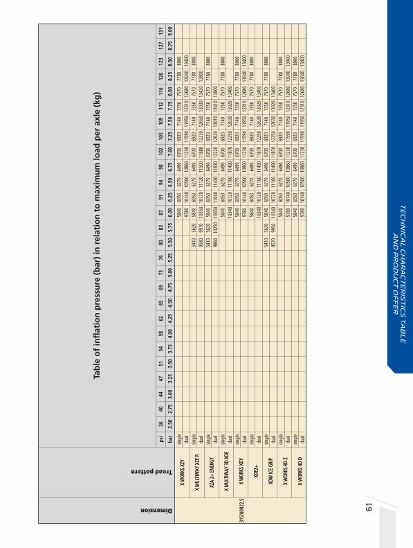
61
Tab
le o
f in
flat
ion
pre
ssu
re (
bar
) in
rel
atio
n t
o m
axim
um
load
per
axl
e (k
g)
Dimension
Tread pattern
X W
ORKS
XZY
X M
ULTI
WAY
XZE
R
XZA
2+ E
NERG
Y
X M
ULTI
WAY
3D
XDE
X W
ORKS
XDY
XDE2
+
XDW
ICE
GRIP
X W
ORKS
HD
Z
X W
ORKS
HD
D
X W
ORKS
XZY
X M
ULTI
WAY
XZE
R
XZA
2+ E
NERG
Y
X M
ULTI
WAY
3D
XDE
X W
ORKS
XDY
XDE2
+
XDW
ICE
GRIP
X W
ORKS
HD
Z
X W
ORKS
HD
D
58
40
6050
62
70
6490
67
00
6920
71
40
7350
75
70
7780
80
00
9780
10
140
1050
0 10
860
1123
0 11
590
1195
0 12
310
1268
0 13
040
1340
0
54
10
5620
58
40
6050
62
70
6490
67
00
6920
71
40
7350
75
70
7780
80
00
9580
99
70
1035
0 10
730
1112
0 11
500
1188
0 12
270
1265
0 13
030
1342
0 13
800
54
10
5620
58
40
6050
62
70
6490
67
00
6920
71
40
7350
75
70
7780
80
00
9860
10
250
1065
0 11
040
1143
0 11
830
1222
0 12
620
1301
0 13
410
1380
0
5840
60
50
6270
64
90
6700
69
20
7140
73
50
7570
77
80
8000
10
340
1072
0 11
100
1149
0 11
870
1225
0 12
630
1302
0 13
400
5840
60
50
6270
64
90
6700
69
20
7140
73
50
7570
77
80
8000
97
80
1014
0 10
500
1086
0 11
230
1159
0 11
950
1231
0 12
680
1304
0 13
400
5840
60
50
6270
64
90
6700
69
20
7140
73
50
7570
77
80
8000
10
340
1072
0 11
100
1149
0 11
870
1225
0 12
630
1302
0 13
400
5410
56
20
5840
60
50
6270
64
90
6700
69
20
7140
73
50
7570
77
80
8000
95
70
9950
10
340
1072
0 11
100
1149
0 11
870
1225
0 12
630
1302
0 13
400
5840
60
50
6270
64
90
6700
69
20
7140
73
50
7570
77
80
8000
97
80
1014
0 10
500
1086
0 11
230
1159
0 11
950
1231
0 12
680
1304
0 13
400
5840
60
50
6270
64
90
6700
69
20
7140
73
50
7570
77
80
8000
97
80
1014
0 10
500
1086
0 11
230
1159
0 11
950
1231
0 12
680
1304
0 13
400
sin
gle
dual
s
ingl
e
du
al
sin
gle
dual
s
ingl
e
du
al
sin
gle
dual
s
ingl
e
du
al
sin
gle
dual
s
ingl
e
du
al
sin
gle
dual
65
69
73
76
80
83
87
91
94
98
10
2 10
5 10
9 11
2 11
6
4.
50
4.75
5.
00
5.25
5.
50
5.75
6.
00
6.25
6.
50
6.75
7.
00
7.25
7.
50
7.75
8.
00
12
0 12
3 12
7 13
1
8.2
5 8.
50
8.75
9.
00
ps
i 36
40
44
47
51
54
58
62
ba
r 2.
50
2.75
3.
00
3.25
3.
50
3.75
4.
00
4.25
315/
80R2
2.5
Te
ch
nic
al
ch
ar
ac
te
ris
tic
s t
ab
le
a
nd
pr
od
uc
t o
ff
er

62
Te
ch
nic
al C
ha
ra
ct
er
ist
ics
o
ff
ro
ad
siz
es
2 Dimension
Tread Pattern
CategoryType
PR (Ply Rating)
Load / Speed Index
Norminal pressure for unique point (bar)
Original tread depth
Nominal load per axle (single) (kg)
Nominal pressure for load (single) (bar)
Nominal load per axle (dual) (kg)
Nominal pressure for load (dual) (bar)
Maximum section width in service (mm)
Maximum diameter in service (mm) (1)
Rolling circumference (mm)
Approved rim(s) ETRTO
Laden section width (mm) (2)
Free section width (mm) (2)
Diameter (mm) (2)
Static laden radius (mm) (2)
Rolling circumference (mm) (2)
Minimum dual spacing (mm) (2)
Recommended rim(s) by MICHELIN
Tube
Flap
Unique point (3)
32
5/85
R16
XML
4 TL
137J
13
4K
4.50
16
.5
4600
4.
50
4.
50
338
992
9.
0
25
5/10
0R16
XZ
L 4
TL
12
6K
134J
5.
75
16.5
34
00
4.50
26
0 94
6
16-6
.00
G
27
5/80
R20
XZL
4 TL
8
128K
15
.2
3600
4.
20
289
974
9
- W9
- 9 S
DC
33
5/80
R20
XZL
4 TL
16
14
1K
17.8
51
50
4.30
9-W
9-9
SDC-
W10
DW
10-1
1-11
SDC
-W11
DW
11-1
2-12
SDC
36
5/80
R20
XZL
4 TL
152K
19
.9
7100
6.
00
11
-11
SDC-
12-1
2 SD
C
47
5/80
R20
XML
4 TL
166G
23
.5 1
0600
6.
00
14
.0V5
°
365/
85R2
0 XZ
L 4
TL
16
4G
22.5
100
00
7.50
10.0
-10.
00V-
10.0
0W
39
5/85
R20
XZL 2
4
TL
16
8K
164L
8.
50
20.0
112
00
8.50
40
1 12
20
XZ
L 4
TL
16
8G
161J
8.
50
25.8
112
00
8.50
10.0
-10.
00V-
10.0
0W
9.
00R2
0 XL
4
TT
14
0/13
7K
17.0
50
00
7.00
92
00
7.00
26
8 10
38
6.
0-6.
00T-
6.5-
B6.5
-7.0
B7
.0-7
.33V
-7.5
-B7.
5
Seal
364
327
98
4 44
9 29
80
9.
0
Jt
1967
286
255
92
3 42
6 28
10
16
-6.5
0 H
Jt 19
67
305
280
93
9 43
1 28
50
9
20 P
23
0-20
LB /
20x8
.50
381
345
103
7 47
3 31
40
11
20
P
310-
20LB
/ 20
x10.
00
Jt 16
81
410
372
109
6 50
1 33
30
11
20
Q
310-
20LB
/ 20
x10.
00
Jt 14
43
526
480
127
2 58
1 38
59
14
.0V
4
11 3
68 1
144
520
3460
20-1
0.00
W
20 S
28
0-20
L
429
388
117
6 53
4 35
84
20
-10,
00 W
425
388
118
9 54
2 36
00
20
-10.
00 W
20
S
280-
20L
Jt 14
43
278
252
103
2 47
9 31
48 2
85
7.0
20 M
20
0-20
L / 2
0x7.
50
• (1)
ETRT
O ra
ting (
stand
ard v
alue,
the E
TRTO
stan
dard
rim
may b
e diff
erent
to th
e rim
reco
mmen
ded b
y MIC
HELIN
). • (
2) M
ICHE
LIN ra
ting,
value
mea
sured
on ri
m rec
omme
nded
by M
ICHE
LIN. •
(3) U
nique
point
: load
capa
city/a
utho
rized
addit
ional
spee
d pair
Load
varia
tions
acco
rding
to sp
eed d
o not
apply
to th
e uniq
ue po
int.

63
Tab
le o
f in
flat
ion
pre
ssu
re (
bar
) in
rel
atio
n t
o m
axim
um
load
per
axl
e (k
g)
Dimension
Tread pattern
sin
gle
3290
35
00
3720
39
40
4160
43
80
dual
- -
- -
- -
sin
gle
2430
25
90
2750
29
10
3080
32
40
dual
- -
- -
- -
sin
gle
2730
29
10
3090
32
70
3435
36
00
dual
- -
- -
- -
singl
e
du
al
-
- -
- -
- s
ingl
e
du
al
sin
gle
5890
62
80
6670
70
70
7460
78
50
dual
- -
- -
- -
sin
gle
dual
s
ingl
e
du
al
sin
gle
dual
s
ingl
e
30
60
3230
du
al
56
40
5940
46
00
-
34
00
-
6500
67
00
6900
71
00
-
- -
-
82
40
8640
90
30
9420
98
10
1021
0 10
600
- -
- -
- -
-
69
70
7270
75
80
7880
81
80
8480
87
90
9090
93
90
9700
10
000
- -
- -
- -
- -
- -
-
81
70
8480
87
80
9080
93
80
9690
99
90
1029
0 10
590
1090
0 11
200
-
- -
- -
- -
- -
- -
81
70
8480
87
80
9080
93
80
9690
99
90
1029
0 10
590
1090
0 11
200
-
- -
- -
- -
- -
- -
33
90
3550
37
10
3870
40
30
4190
43
50
4520
46
80
4840
50
00
6230
65
30
6830
71
20
7420
77
20
8010
83
10
8610
89
00
9200
32
5/85
R16
XML
255
/100
R16
XZL
27
5/80
R20
XZL
33
5/80
R20
XZL
36
5/80
R20
XZL
47
5/80
R20
XML
36
5/85
R20
XZL
39
5/85
R20
XZL 2
XZL
9.
00R2
0 XL
65
69
73
76
80
83
87
91
94
98
10
2 10
5 10
9 11
2 11
6
4.
50
4.75
5.
00
5.25
5.
50
5.75
6.
00
6.25
6.
50
6.75
7.
00
7.25
7.
50
7.75
8.
00
12
0 12
3 12
7 13
1 13
4
8.2
5 8.
50
8.75
9.
00
9.25
ps
i 36
40
44
47
51
54
58
62
ba
r 2.
50
2.75
3.
00
3.25
3.
50
3.75
4.
00
4.25
For P
ress
ure,
Plea
se C
onsu
lt M
ICHE
LIN’s
Repr
esen
tativ
es
Te
ch
nic
al
ch
ar
ac
te
ris
tic
s t
ab
le
a
nd
pr
od
uc
t o
ff
er

64
Dimension
Tread Pattern
CategoryType
PR (Ply Rating)
Load / Speed Index
Norminal pressure for unique point (bar)
Original tread depth
Nominal load per axle (single) (kg)
Nominal pressure for load (single) (bar)
Nominal load per axle (dual) (kg)
Nominal pressure for load (dual) (bar)
Maximum section width in service (mm)
Maximum diameter in service (mm) (1)
Rolling circumference (mm)
Approved rim(s) ETRTO
Laden section width (mm) (2)
Free section width (mm) (2)
Diameter (mm) (2)
Static laden radius (mm) (2)
Rolling circumference (mm) (2)
Minimum dual spacing (mm) (2)
Recommended rim(s) by MICHELIN
Tube
Flap
Unique point (3)
11
.00R
20
XZL
4 TL
16
15
0/14
6K
18.0
67
00
8.00
12
000
8.00
29
7 11
04
7.
33V-
7.5-
B7.5
-8.0
8.
0V-B
8.0-
8.5
8.
50V-
B8.5
-9.0
0V
12.0
0R20
XZ
L 4
TL
18
154/
149K
18
.7
7500
8.
50
1300
0 8.
50
319
1146
7.33
V-8.
0-8.
0V-B
8.0
8.
5-8.
50V-
B8.5
9.
0-9.
00V
XML
4 TL
18
14
9/14
6J
19.5
65
00
7.20
12
000
7.20
31
9 11
58
7.
33V-
8.0-
8.0V
B8
.0-8
.5-8
.50V
B8
.5-9
.0-9
.00V
14
.00R
20
XM
L 4
TL
15
3G
149K
6.
20
24.4
73
00
6.20
37
7 12
68
9.
0-10
.0-1
0.00
V
10
.00W
XZL+
4
TL
16
4/16
1J
166G
7.
90
22.3
100
00
7.80
18
500
7.80
XZL+
4
TL
22
164/
160J
16
6G
7.90
22
.3 1
0000
7.
60
1800
0 7.
60
XZ
L 4
TL
22
164/
160G
15
6J
7.60
23
.3 1
0000
7.
60
1600
0 7.
60
384
1258
9.0-
9.00
V-10
.0
10
.00V
-10.
00W
XS
4 TL
160/
157F
16
.5
9000
7.
00
1650
0 7.
00
377
1282
9.0-
10.0
-10.
00V
10
.00W
16
.00R
20
XZL
4 TL
173/
170G
27
.0 1
3000
7.
50
2400
0 7.
50
482
1413
Seal
330
299
109
2 50
8 33
40 3
38
8.0
20 P
20
x8.5
0MI
344
311
113
1 52
7 34
60 3
52
8.5
20 Q
23
0-20
LB /
20x8
.50
339
308
113
1 52
6 34
43 3
49
8.5
20 Q
421
383
125
8 58
1 38
30
10
.00W
428
386
125
8 57
8 38
32 4
36
20-1
0,00
W
428
386
125
8 57
8 38
32 4
36
20-1
0,00
W
427
384
125
8 57
9 38
26 4
34
10.0
0
410
369
123
8 56
6 37
72 4
17
10.0
0W
488
438
134
3 60
9 40
90 4
95
10.0
0W
20 V
31
0-20
LB /
20x1
0.00
• (1)
ETRT
O ra
ting (
stand
ard v
alue,
the E
TRTO
stan
dard
rim
may b
e diff
erent
to th
e rim
reco
mmen
ded b
y MIC
HELIN
). • (
2) M
ICHE
LIN ra
ting,
value
mea
sured
on ri
m rec
omme
nded
by M
ICHE
LIN. •
(3) U
nique
point
: load
capa
city/a
utho
rized
addit
ional
spee
d pair
Load
varia
tions
acco
rding
to sp
eed d
o not
apply
to th
e uniq
ue po
int.
Te
ch
nic
al C
ha
ra
ct
er
ist
ics
o
ff
ro
ad
siz
es
2
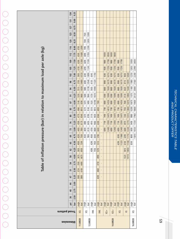
65
Tab
le o
f in
flat
ion
pre
ssu
re (
bar
) in
rel
atio
n t
o m
axim
um
load
per
axl
e (k
g)
Dimension
Tread pattern
sin
gle
30
00
3250
35
00
3670
38
30
dual
58
00
6100
64
00
6670
69
30 s
ingl
e
du
al
sin
gle
40
90
dual
75
50 s
ingl
e
4200
44
60
4730
49
90
5250
du
al
- -
- -
- s
ingl
e
du
al
sin
gle
du
al
sin
gle
dual
s
ingl
e
55
20
5810
du
al
10
110
1065
0 s
ingl
e
du
al
40
00
4200
44
00
4590
47
70
4960
51
40
5330
55
10
5700
59
00
6100
63
00
6500
67
00
7200
75
00
7800
81
70
8540
89
10
9290
96
60
1003
0 10
400
1072
0 11
040
1136
0 11
680
1200
0
4500
46
90
4880
50
70
5270
54
70
5680
58
80
6080
62
80
6490
66
90
6890
70
90
7300
75
00
78
00
8130
84
50
8780
91
40
9490
98
40
1019
0 10
540
1089
0 11
240
1159
0 11
950
1230
0 12
650
1300
0
4290
45
00
4700
49
10
5110
53
10
5520
57
20
5930
61
30
6340
79
20
8300
86
80
9060
94
30
9810
10
190
1057
0 10
940
1132
0 11
700
5510
57
80
6040
63
00
6560
68
30
7300
-
- -
- -
- -
6890
71
90
7490
77
80
8080
83
80
8680
89
80
9280
95
80
9880
10
000
12
400
1293
0 13
470
1401
0 14
550
1509
0 15
630
1617
0 16
710
1725
0 17
780
1850
0
6890
71
90
7490
77
80
8080
83
80
8680
89
80
9280
95
80
9880
10
000
12
400
1293
0 13
470
1401
0 14
550
1509
0 15
630
1617
0 16
710
1725
0 17
780
1800
0
6290
65
90
6890
71
90
7490
77
80
8080
83
80
8680
89
80
9280
95
80
9880
113
20
1186
0 12
400
1293
0 13
470
1401
0 14
550
1509
0 15
630
1617
0 16
710
1725
0 17
780
6100
63
90
6680
69
70
7260
75
50
7840
81
30
8420
87
10
9000
111
80
1171
0 12
240
1277
0 13
310
1384
0 14
370
1490
0 15
440
1597
0 16
500
8300
86
90
9090
94
90
9880
10
280
1067
0 11
070
1146
0 11
860
1225
0 12
650
1300
0
1581
0 16
530
1725
0 17
960
1868
0 19
400
2012
0 20
840
2156
0 22
280
2299
0 24
000
11
.00R
20
XZL
12
.00R
20
XZL
XML
14.0
0R20
XM
L
XZL+
XZL+
XZL
XS
16.0
0R20
XZ
L
65
69
73
76
80
83
87
91
94
98
10
2 10
5 10
9 11
2 11
6
4.
50
4.75
5.
00
5.25
5.
50
5.75
6.
00
6.25
6.
50
6.75
7.
00
7.25
7.
50
7.75
8.
00
12
0 12
3 12
7 13
1 13
4
8.2
5 8.
50
8.75
9.
00
9.25
ps
i 36
40
44
47
51
54
58
62
ba
r 2.
50
2.75
3.
00
3.25
3.
50
3.75
4.
00
4.25
Te
ch
nic
al
ch
ar
ac
te
ris
tic
s t
ab
le
a
nd
pr
od
uc
t o
ff
er

66
Dimension
Tread Pattern
CategoryType
PR (Ply Rating)
Load / Speed Index
Norminal pressure for unique point (bar)
Original tread depth
Nominal load per axle (single) (kg)
Nominal pressure for load (single) (bar)
Nominal load per axle (dual) (kg)
Nominal pressure for load (dual) (bar)
Maximum section width in service (mm)
Maximum diameter in service (mm) (1)
Rolling circumference (mm)
Approved rim(s) ETRTO
Laden section width (mm) (2)
Free section width (mm) (2)
Diameter (mm) (2)
Static laden radius (mm) (2)
Rolling circumference (mm) (2)
Minimum dual spacing (mm) (2)
Recommended rim(s) by MICHELIN
Tube
Flap
Unique point (3)
52
5/65
R20.
5 XS
4
TL
20
173F
16
.8 1
3000
8.
00
551
1231
16.0
0
24
/70R
20.5
XS
4
TL
17
6F
16.8
142
00
6.00
18.0
0
24
/70R
21
XZL
4 TL
16
17
6G
25.0
142
00
6.00
20
0 68
7
44
5/65
R22.
5 XZ
L 4
TL
16
8G
21.0
112
00
8.00
14.0
0
13
R22.
5 XZ
L 4
TL
18
154/
150K
20
.2
7500
8.
00
1340
0 8.
00
326
1146
9.00
- 9.
75
12
.00R
24
XDL
4 TT
LRJ
30.4
80
00
7.50
14
600
7.50
8.50
, 8.0
0
Seal
558
521
120
0 54
8 36
39
16
.00
19.5
/20.
5 UD
661
602
137
4 62
0 41
50
18
.00
20.5
WAM
D
663
608
138
8 63
1 42
00
18
.00
486
448
116
8 53
7 35
50
14
.00
338
307
113
0 52
5 34
50 3
47
9.00
356
323
125
5 58
6 39
44 3
58
8.50
• (1)
ETRT
O ra
ting (
stand
ard v
alue,
the E
TRTO
stan
dard
rim
may b
e diff
erent
to th
e rim
reco
mmen
ded b
y MIC
HELIN
). • (
2) M
ICHE
LIN ra
ting,
value
mea
sured
on ri
m rec
omme
nded
by M
ICHE
LIN. •
(3) U
nique
point
: load
capa
city/a
utho
rized
addit
ional
spee
d pair
Load
varia
tions
acco
rding
to sp
eed d
o not
apply
to th
e uniq
ue po
int.
Te
ch
nic
al C
ha
ra
ct
er
ist
ics
o
ff
ro
ad
siz
es
2

67
Tab
le o
f in
flat
ion
pre
ssu
re (
bar
) in
rel
atio
n t
o m
axim
um
load
per
axl
e (k
g)
Dimension
Tread pattern
sin
gle
dual
s
ingl
e
90
00
9500
10
000
1050
0
dual
- -
- -
sin
gle
9000
95
00
1000
0 10
500
du
al
-
- -
- s
ingl
e
du
al
sin
gle
dual
s
ingl
e
du
al
85
00
8875
92
50
9625
10
000
1037
5 10
750
1112
5 11
500
1187
5 12
250
1262
5 13
000
- -
- -
- -
- -
- -
- -
-
110
00
1150
0 12
000
1250
0 13
000
1360
0 14
200
- -
- -
- -
-
110
00
1150
0 12
000
1250
0 13
000
1360
0 14
200
- -
- -
- -
-
73
60
7680
80
00
8320
86
40
8960
92
80
9600
99
20
1024
0 10
560
1088
0 11
200
- -
- -
- -
- -
- -
- -
-
49
30
5140
53
60
5570
57
90
6000
62
10
6430
66
40
6860
70
70
7290
75
00
8810
91
90
9570
99
50
1034
0 10
720
1110
0 11
490
1187
0 12
250
1263
0 13
020
1340
0
5090
53
30
5580
58
20
6060
63
00
6550
67
90
7030
72
70
7520
77
60
8000
92
90
9730
10
180
1062
0 11
060
1150
0 11
950
1239
0 12
830
1327
0 13
720
1416
0 14
600
525/
65R2
0.5
XS
24
/70R
20.5
XS
24
/70R
21
XZL
445/
65R2
2.5
XZL
13
R22.
5 XZ
L
12
.00R
24
XDL
65
69
73
76
80
83
87
91
94
98
10
2 10
5 10
9 11
2 11
6
4.
50
4.75
5.
00
5.25
5.
50
5.75
6.
00
6.25
6.
50
6.75
7.
00
7.25
7.
50
7.75
8.
00
12
0 12
3 12
7 13
1 13
4
8.2
5 8.
50
8.75
9.
00
9.25
ps
i 36
40
44
47
51
54
58
62
ba
r 2.
50
2.75
3.
00
3.25
3.
50
3.75
4.
00
4.25
Te
ch
nic
al
ch
ar
ac
te
ris
tic
s t
ab
le
a
nd
pr
od
uc
t o
ff
er

BENEFITS:
Safety made to last • Shorter wet braking distance when new (5%) and when worn (11%) compared with leading competitor*
Your partner for longer • Michelin's excellence in longevity proven by +25% more mileage vs. previous generation**
• Less downtime for you and your business
Every drop counts • 12%*** superior rolling resistance resulting in reduced fuel consumption giving you the environmental advantage.
68
TECHNOLOGIES
Safety • With the Evergrip technology • Innovative compound with higher density of silica and carbon black to improve wet grip and reduce breaking distances (when new or worn).
Strength • From the sidewall kerbing protectors. • The position of kerbing protectors on the sidewall has been calculated to optimize tyre protection in all circumstances.
Technical characteristicstable and product offer
2
MICHELIN AGILIS3 FOR LIGHT TRUCK
TECHNOLOGYEVERGRIP
Optimized compound
TECHNOLOGYEVERGRIP
U-SHAPE GROOVE
TECHNOLOGYSHIELDS REINFORCED
SIDEWALL RUBBER
* Wet braking test 80 to 0 kph, conducted by TÜV Rheinland Thailand Ltd, on Michelin’s request, in June 2020 on dimension 215/70R15C on Toyota Hiace Commuter, laden condition of 2,950 kg GVW. Comparing new and worn MICHELIN Agilis 3 RC versus three other competitor brands of tyres. Wet braking reference: TÜV Rheinland Thailand Ltd, Techincal Report 242107901 001** Test results from Michelin internal test, conducted on real roads in Thailand, with 215/70R15C tyres fitted in Ford Ranger (Ute car). Load: Front axle: 1446kg / Rear axle: 1443 kg. Wear life index was calculated by the “Harmonic average” of 4 tyres assuming the Customer regularly rotates tyres.*** Rolling Resistance Test performed at Thailand Automotive Institute and certified by TÜV Rheinland Thailand Ltd, on Michelin’s request, in December 2019, on dimension 215/70R15C. Comparing MICHELIN Agilis 3 RC versus other competitor brands. TÜV Reference Report No. 242105960 001.
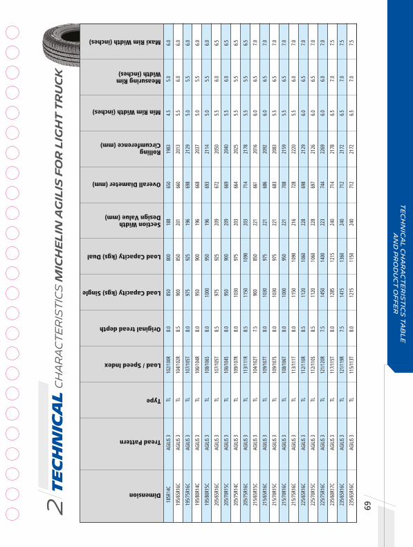
Te
ch
nic
al Ch
ar
ac
te
ris
tic
s M
ICH
EL
IN A
GIL
IS F
OR
LIG
HT
TR
UC
K2
Dimension
Tread Pattern
Type
Load / Speed Index
Original tread depth
Load Capacity (kgs) Single
Load Capacity (kgs) Dual
Section Width Design Value (mm)
Overall Diameter (mm)
Min Rim Width (inches)
Maxi Rim Width (inches)
RollingCircumference (mm)
18
5R14
C AG
ILIS
3 TL
10
2/10
0R
8.0
850
800
188
650
1983
4.
5 5.
0 6.
0
19
5/65
R16C
AG
ILIS
3 TL
10
4/10
2R
8.5
900
850
201
660
2013
5.
5 6.
0 6.
0
19
5/75
R16C
AG
ILIS
3 TL
10
7/10
5T
8.0
975
925
196
698
2129
5.
0 5.
5 6.
0
19
5/80
R14C
AG
ILIS
3 TL
10
6/10
4R
8.0
950
900
196
668
2037
5.
0 5.
5 6.
0
19
5/80
R15C
AG
ILIS
3 TL
10
8/10
6S
8.0
1000
95
0 19
6 69
3 21
14
5.0
5.5
6.0
20
5/65
R16C
AG
ILIS
3 TL
10
7/10
5T
8.5
975
925
209
672
2050
5.
5 6.
0 6.
5
20
5/70
R15C
AG
ILIS
3 TL
10
6/10
4S
8.0
950
900
209
669
2040
5.
5 6.
0 6.
5
20
5/75
R14C
AG
ILIS
3 TL
10
9/10
7R
8.0
1030
97
5 20
3 66
4 20
25
5.5
5.5
6.5
20
5/75
R16C
AG
ILIS
3 TL
11
3/11
1R
8.5
1150
10
90
203
714
2178
5.
5 5.
5 6.
5
21
5/65
R15C
AG
ILIS
3 TL
10
4/10
2T
7.5
900
850
221
661
2016
6.
0 6.
5 7.
0
21
5/65
R16C
AG
ILIS
3 TL
10
9/10
7T
8.0
1030
97
5 22
1 68
6 20
92
6.0
6.5
7.0
21
5/70
R15C
AG
ILIS
3 TL
10
9/10
7S
8.0
1030
97
5 22
1 68
3 20
83
5.5
6.5
7.0
21
5/70
R16C
AG
ILIS
3 TL
10
8/10
6T
8.0
1000
95
0 22
1 70
8 21
59
5.5
6.5
7.0
21
5/75
R16C
AG
ILIS
3 TL
11
3/11
1T
8.0
1150
10
90
216
728
2220
5.
5 6.
0 7.
0
22
5/65
R16C
AG
ILIS
3 TL
11
2/11
0R
8.5
1120
10
60
228
698
2129
6.
0 6.
5 7.
0
22
5/70
R15C
AG
ILIS
3 TL
11
2/11
0S
8.5
1120
10
60
228
697
2126
6.
0 6.
5 7.
0
22
5/75
R16C
AG
ILIS
3 TL
12
1/12
0R
7.5
1450
14
00
223
744
2269
6.
0 6.
0 7.
0
23
5/60
R17C
AG
ILIS
3 TL
11
7/11
5T
8.0
1285
12
15
240
714
2178
6.
5 7.
0 7.
5
23
5/65
R16C
AG
ILIS
3 TL
12
1/11
9R
7.5
1415
13
60
240
712
2172
6.
5 7.
0 7.
5
23
5/65
R16C
AG
ILIS
3 TL
11
5/11
3T
8.0
1215
11
50
240
712
2172
6.
5 7.
0 7.
5
69
Te
ch
nic
al
ch
ar
ac
te
ris
tic
s t
ab
le
a
nd
pr
od
uc
t o
ff
er
Measuring RimWidth (inches)

70
Technical characteristicstable and product offer
2
MICHELIN XCD2 FOR LIGHT TRUCK
Incorrect tyre usage and driving can lead to accidents. To reduce any possible risk, Michelin recommends
users to follow the tyre user manual, tyre sidewall information and vehicle user manual strictly. The tyre
user manual is available at all Michelin dealers. For more information, please visit www.michelin.com.au
with a combination of rubber compounds
robustness
with maximum bead strength
All claims are made in comparison to the previous generation of MICHELIN XCD tyres.*Based on MICHELIN XCD2 size 205/70 R15C
hard outer layer
michelin XCD2
michelin XCD
27%
soft inner layer
01
02
03
handling
with rubber insert on lower sidewall
• Hard outer layer of 100% natural rubber protects casing ply
• Soft inner layer of synthetic rubber content lowers heat generation
• Five more wires in bead package• 20% stronger bead
• Improved resistance to bead failure• Improved damage resistance during fitting
and removal
• 27% increased height*• 45% higher bead reinforcement*
• More rigid sidewall• Improved handling stability
BENEFITS:
MICHELIN XCD2 tyres are the reference for usage in the most challenging conditions.
HEight loading capacity • Perfect choice for commercial users.
Robust and strong • Built to endure and last with ability to carry heavy loads with maximum safety.

Te
ch
nic
al Ch
ar
ac
te
ris
tic
s M
ICH
EL
IN X
CD
2 F
OR
LIG
HT
TR
UC
K2
Dimension
Pattern
Type
Load Index
Load Index (Dual)
Speed Index
Load Capacity (kgs) Single
Load Capacity (Kgs) Dual
Section Width Design Value (mm)
Overall Diameter (mm)
Rolling Circumference (mm)
Min Rim Width (inches)
Measuring Rim Width (inches)
Maxi Rim Width (inches)
19
5R14
C
XCD
TL
106
P
950
19
8 66
6 20
31
5.00
5.
50
6.00
20
5R14
C
XCD
TL
109
P
1030
208
686
2092
5.
50
6.00
6.
50
21
5R14
C
XCD
TL
112
P
1120
218
714
2178
5.
50
6.00
7.
00
20
5/70
R15C
XC
D TL
10
6
Q 95
0
209
669
2040
5.
50
6.00
6.
50
21
5R15
C XC
D TL
11
2
Q 11
20
21
8 72
5 22
11
5.50
6.
00
7.00
20
5/75
R14C
XC
D2
TL
109
107
P 10
30
975
203
664
2025
5.
50
5.50
6.
50
21
5/75
R14C
XC
D2
TL
112
110
P 11
20
1060
21
6 67
8 20
68
5.50
6.
00
7.00
22
5/75
R14C
XC
D2
TL
115
113
P 12
15
1150
22
3 69
3 21
14
6.00
6.
50
7.00
20
5/70
R15C
*
XCD2
TL
10
6 10
4 S
950
900
209
669
2040
5.
50
6.00
6.
50
22
5/75
R15C
*
XCD2
TL
11
6 11
4 Q
1250
11
80
223
719
2193
6.
00
7.00
7.
50
71
Te
ch
nic
al
ch
ar
ac
te
ris
tic
s t
ab
le
a
nd
pr
od
uc
t o
ff
er


09
3
Ap
pe
nd
ix
Appendix
• Tube & Flap assembly• Truck and Bus Wheel• Accessories• Conversion Table• General Information
7478
80
8285

74
3Appendix
Tyre/Tube/Flap Assembly
Tyre dimensions
Tube Valve
Reference Reference Bend type
Flap Plates
Reference
For other CAIs not listed in this table, please contact your Michelin representative.
7.50R15 15/16J 570 Single
8.25R15 15K 1221 Double
10.00R15 15P 582 Triple
15P 1548 Straight
7.00R16 16J 77-95 TR77A Single, Fixed valve
7.50R16 16J 77-95 TR77A Single, Fixed valve
8.25R16 16K 77-95 TR77A Single, Fixed valve
8.25R20 20K 1021 Single
9.00R20 20M+ 175 95 TR175A Single, Fixed valve
10.00R20 20N+ 78 95 TR78A Single, Fixed valve
11.00R20 20P 78 95 TR78A Single, Fixed valve
12.00R20 20Q 1158 Single
335/80R20
14.00R20 G20 20S 582 Triple
365/85R20 20S 582 Triple
395/85R20 20S 582 Triple
16.00R20
20V 1188 Single
20V 1548 Straight
12.00R24 24Q 582 Triple
325/95R24 24Q 582 Triple
Flap 15X6.00 Plastic
Flap 15X6.00 Plastic
Flap 15X7.50 Plastic
Flap 16x6.00 Metal
Flap 16x6.00 Metal
Flap 16x6.00 Metal
Flap 20x7.50 Metal
Flap 20x7.50 Metal
Flap 20x7.50 Metal
Flap 20X8.50 Metal
Flap 20X8.50 Metal
Flap 20X10.00 Plastic
Flap 20X8.50 Metal
Flap 20X10.00 Plastic
Flap 20X10.00 Plastic
Flap 24/25X8.50 E Plastic
Flap 24/25X8.50 E Plastic
Flap 15X6.00 Plastic
Flap 15X6.00 Plastic
Flap 15X7.50 Plastic
Flap 16x6.00 Metal
Flap 16x6.00 Metal
Flap 16x6.00 Metal
Flap 20x7.50 Metal
Flap 20x7.50 Metal
Flap 20x7.50 Metal
Flap 20X8.50 Metal
Flap 20X8.50 Metal
Flap 20X10.00 Plastic
Flap 20X8.50 Metal
Flap 20X10.00 Plastic
Flap 20X10.00 Plastic
Flap 24/25X8.50 E Plastic
Flap 24/25X8.50 E Plastic

Ap
pe
nd
ix
Tyre size Rim width 15X6.00 15X7.50 16X6.00+
Flap Groups for use in MICHELIN tyres
75
Bold = Standard rim width
Preferred fitment on this rim
Fitment permitted but the flap may be wide
Fitment permitted but the flap may be narrow
7.00R15
5.00
7.50R15
5.50
6.00
6.50
8.25R15
5.00
5.50
6.00
6.50
10.00R15
6.50
7.00
7.50
7.00R16
5.00
5.50
6.00
7.50R16
5.50
6.00
6.50
8.25R16
6.00
6.50

3Appendix
Flap Groups for use in MICHELIN tyres
Tyre size Rim width 20X7.50 20X8.50 20X10.00 25/25X8.25 240-24/25L
76
Tube and Flap Assembly
Bold = Standard rim width
Preferred fitment on this rim
Fitment permitted but the flap may be wide
Fitment permitted but the flap may be narrow
8.25R20
6.00
6.50
7.00
9.00R20
6.50
7.00
7.50
10.00R20
7.00
7.50
8.00
11.00R20
7.50
8.00
8.50
12.00R20 8.00
335/80R20 8.50
9.00
14.00R20 9.00
365/80R20 10.00
16.00R20
10.00
11.25
12.00R24
8.00
8.50
9.00

Ap
pe
nd
ix

3Appendix
78
Truck and Bus Wheel
CharacteristicsA = Nominal Wheel Diameter D = OffsetB = Inside width E = Diameter of the fixing holes (PCD)C = Centre bore N = Number of fixing holes Dual Spacing = 2 x offset
Tube Type Wheel Tubeless Wheel
Dual spacing Dual spacing
HUBC E A
B
N
D
OFFSET DB B
N
OFFSET
seat
ˇ
C E
A
seat
ˇ
Types of Fixing
Cylindrical Spherical nut Conical nut
80˚
Spherical nut orSpherical washer + CylindricalSingle
80˚80˚
SPIGOT(P or M)
Hub centering
Budd/AMJ(American/Japanese)
SphericalDIN
Conical(AN)Twinned
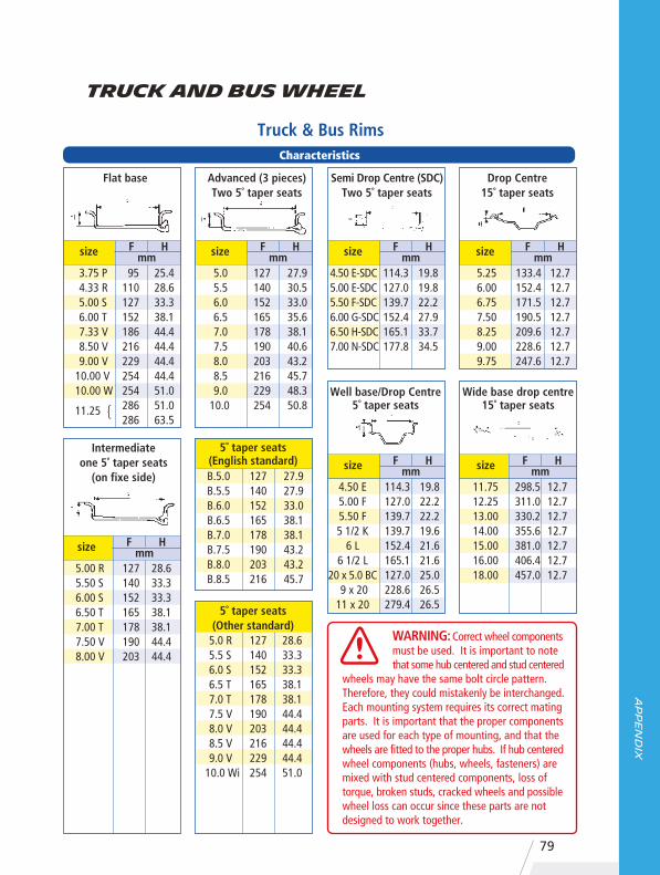
09
Ap
pe
nd
ix
79
Truck & Bus RimsCharacteristics
3.75 P 4.33 R 5.00 S 6.00 T 7.33 V 8.50 V 9.00 V 10.00 V 10.00 W 11.25
95 110 127 152 186 216 229 254 254 286 286
25.4 28.6 33.3 38.1 44.4 44.4 44.4 44.4 51.0 51.0 63.5
size F Hmm
{
Flat base
5.00 R 5.50 S 6.00 S 6.50 T 7.00 T 7.50 V 8.00 V
127140152165178190203
28.6 33.3 33.3 38.1 38.1 44.4 44.4
size F Hmm
Intermediateone 5˚ taper seats
(on fixe side)
5.0 5.5 6.0 6.5 7.0 7.5 8.0 8.5 9.0 10.0
127 140 152 165 178 190 203 216 229 254
27.9 30.5 33.0 35.6 38.1 40.6 43.2 45.7 48.3 50.8
size F Hmm
Advanced (3 pieces)Two 5˚ taper seats
5.0 R 5.5 S 6.0 S 6.5 T 7.0 T 7.5 V 8.0 V 8.5 V 9.0 V 10.0 Wi
127 140 152 165 178 190 203 216 229 254
28.6 33.3 33.3 38.1 38.1 44.4 44.4 44.4 44.4 51.0
5˚ taper seats(Other standard)
B.5.0B.5.5B.6.0B.6.5B.7.0B.7.5B.8.0B.8.5
127140152165178190203216
27.9 27.9 33.0 38.1 38.1 43.2 43.2 45.7
5˚ taper seats(English standard)
WARNING: Correct wheel components must be used. It is important to note that some hub centered and stud centered wheels may have the same bolt circle pattern. Therefore, they could mistakenly be interchanged. Each mounting system requires its correct mating parts. It is important that the proper components are used for each type of mounting, and that the wheels are fitted to the proper hubs. If hub centered wheel components (hubs, wheels, fasteners) are mixed with stud centered components, loss of torque, broken studs, cracked wheels and possible wheel loss can occur since these parts are not designed to work together.
4.50 E-SDC5.00 E-SDC5.50 F-SDC6.00 G-SDC6.50 H-SDC7.00 N-SDC
114.3 127.0 139.7 152.4 165.1 177.8
19.8 19.8 22.2 27.9 33.7 34.5
size F Hmm
Semi Drop Centre (SDC)Two 5˚ taper seats
4.50 E5.00 F5.50 F5 1/2 K
6 L6 1/2 L
20 x 5.0 BC 9 x 2011 x 20
114.3 127.0 139.7 139.7 152.4 165.1 127.0 228.6 279.4
19.8 22.2 22.2 19.6 21.6 21.6 25.0 26.5 26.5
size F Hmm
Well base/Drop Centre5˚ taper seats
5.25 6.00 6.75 7.50 8.25 9.00 9.75
133.4 152.4 171.5 190.5 209.6 228.6 247.6
12.7 12.7 12.7 12.7 12.7 12.7 12.7
size F Hmm
Drop Centre15˚ taper seats
11.75 12.25 13.00 14.00 15.00 16.00 18.00
298.5 311.0 330.2 355.6 381.0 406.4 457.0
12.7 12.7 12.7 12.7 12.7 12.7 12.7
size F Hmm
Wide base drop centre15˚ taper seats
Truck and Bus Wheel

3Appendix
80
Accessories
Lmm
Amm
Bmm
Hmm α° β°
ETRTO MICHELINV3-04-1V3-04-2V3-04-6V3-04-8V3-04-26V3-05-1
734
578579
119818771221
140
607612880
96
323886389932
374147434266
202020202016
909090909990
138153153167189165
Reference Lmm
Hmm α°
ETRTO MICHELINV3-02-2V3-02-3V3-02-4V3-02-5V3-02-7V3-02-9V3-02-10V3-02-12V3-02-13V3-02-14V3-02-20V3-02-23V3-03-4
57057657710031188115610211157751115875010121010
434444477199115132133138536684
22333920222020202020222915
12095110901009494949094959094
Reference Ø hole ofthe valve ETRTO MICHELIN
V2-01-1V2-01-2
746611
11,315,7
— 990 15,7Plastic ferrule for the fitment of valve746 in 15.7 mm diameter hole
Double bend valve stem
L
A
H
β°B
Single bend valve stem
H
L
Rubber base valves for truck
ØETRTO MICHELIN
V3-08-4 1548 57
Base for truck valve stem
Reference
Reference
a°
a°
ETRTO MICHELIN— 1964 49
Lmm
Valve with straight stem
L
Reference

09
Ap
pe
nd
ix
81
Reference Lmm
Amm
Bmm
Hmm
hmm α° γ°
ETRTO MICHELINV3-06-2V3-06-3V3-06-5V3-06-7
5805815821348
94114131106
44466245
12201918
20202020
17171717
90909090
125140139137
Triple bend valve stem
H
L
h
A B
Mounting a universal valve stem
1. Check that air-tight rubber must be dry and clean when fitting.
2. Screw down the stem until contact is made with the washer.
3. Continue to screw in two complete turns for air-tightness.
4. Tighten the stem further until the final position is reached.
NB : Do not tighten more than recommended above.Do not forget to fit the valve cap which keeps it clean and helpskeep the valve leakproof.
IMPORTANT : do not unscrew
a°
y°
y°
Accessories
Essential accessories
Truck Tyre valve extension
Fixing Clamps for Trucks Tyres valve
extension
When tyres are twinned, in order to avoid abnormal wear and tyre overload problems, it is essential to ensure that twinned tyres are the same size, same manufacture, same type and tread pattern, and that the wear rates and pressures are the same.
Valve extensions fitted to inner twins, permit easy verification of tyre pressures. It is essential to ensure that they are correctly fitted, and supported with the appropriate brackets where necessary.

3Appendix
82
Note : Before any change over please check : • Load capacity • Vehicle clearance • Recommended rim/wheel • Dual spacing
Equivalent Sizes
100 Series 90 Series Low Profile Series 7.50 R 15 215/75 R 17.5
8.25 R 15 9 R 17.5 235/75 R 17.5
10.00 R 15 285/70 R 19.5
7.00 R 16 8 R 17.5 205/75 R 17.5
215/75 R 17.5
7.50 R 16 8.5 R 17.5 225/75 R 17.5
225/80 R 17.5
9.5 R 17.5
8.25 R 16 10 R 17.5
225/90 R 17.5
7.50 R 20 8 R 22.5
8.25 R 20 9 R 22.5
9.00 R 20
10 R 22.5
255/70 R 22.5
275/70 R 22.5
295/80 R 22.5
10.00 R 20 11 R 22.5 275/80 R 22.5
275/70 R 22.5
11.00 R 20
12 R 22.5
295/80 R 22.5
315/80 R 22.5
305/70 R 22.5
315/70 R 22.5
12.00 R 20 13 R 22.5 315/80 R 22.5
235/75 R 17.5
245/70 R 19.5
Conversion Table

09
Ap
pe
nd
ix
83
Tube Type Tubeless Tubeless Tubeless
H/S 100 H/S 90 H/S 80 H/S 70/75
Conversion Table
kPa(kilo pascal)
m/s(meter per second)
kg(kilogram)
m(meter)
1 pound (lb) = 0.4536 kg
1 bar = 14.5 PSI1 bar = 100 kPa
1 kg/cm2 = 98.066 kPa
1 km per hour (km/hr)* = 0.27778 m/s1 mile per hour (m.p.h.) = 0.4470 m/s
1 mile per hour (m.p.h.) = 1.60935 km/h
1 inch (*) = 0.0254 m (or 25.4 mm)1 mile = 1,609 m (or 1.609 km)
Length
Mass
Pressure
Speed
Quantity Units Other Units
Load Range / Ply Rating
B - 4C - 6D - 8E - 10
F - 12G - 14H - 16J - 18
L - 20M -22
Conversion Table

3Appendix
84
* Values in psi and kg/cm2 rounded to the nearest pratical units.
Pressure Unit Conversion Tablebar 1.0 1.5 2.0 2.5 3.0 3.5 4.0 4.5 5.0 5.5 6.0 6.5 7.0 7.5 8.0 8.5 9.0 9.5 10.0 10.5
psi* 15 22 29 36 44 51 58 65 73 80 87 94102109116123131138145152
kg/cm2* 1.0 1.5 2.0 2.5 3.1 3.6 4.1 4.6 5.1 5.6 6.1 6.6 7.1 7.7 8.2 8.7 9.2 9.7 10.2 10.7
kPa 100 150 200 250 300 350 400 450 500 550 600 650 700 750 800 850 900 950 1,000 1,050
Conversion Table
Adjusted Inflation Pressure (psi) when inflating indoors at 18°C
RecommendedPressure (psi)
Outside Ambient Temperature (°C)
7580859095
100105110115120125130
98
10°78838893
103109114119124129134
4°80859095
101106111116122127132137
-1°81879298
103108114119124130135140
-7°838994
100105111116122127133138144
-12°869197
102108113119125130136141147
-18°889399
105111116122128133139145150
-23°9096
102108113119125131137143148154
-29°9298
104110116122128134140146152158
-34°95
101107113119125132138144150156162 166
-40°98
104110116123129135141148154160
-46°100107113119126132139145151158164171
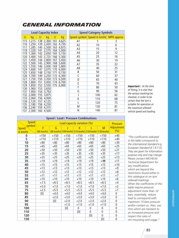
09
Ap
pe
nd
ix
85
General Information Load Capacity Index Speed Category Symbols
130 1,900 153 3,650131 1,950 154 3,750132 2,000 155 3,875133 2,060 156 4,000134 2,120 157 4,125135 2,180 158 4,250136 2,240 159 4,375137 2,300 160 4,500
115 1,215 138 2,360 161 4,625116 1,250 139 2,430 162 4,750117 1,285 140 2,500 163 4,875118 1,320 141 2,575 164 5,000119 1,360 142 2,650 165 5,150120 1,400 143 2,725 166 5,300121 1,450 144 2,800 167 5,450122 1,500 145 2,900 168 5,600123 1,550 146 3,000 169 5,800124 1,600 147 3,075 170 6,000125 1,650 148 3,150 171 6,150126 1,700 149 3,250 172 6,300127 1,750 150 3,350 173 6,500128 1,800 151 3,450 174 6,700129 1,850 152 3,550 175 6,900
LI kg LI kg LI kg Speed symbol Speed in km/hr MPH approx A1 5 3 A2 10 6 A3 15 9 A4 20 12 A5 25 16 A6 30 19 A7 35 22 A8 40 25 B 50 31 C 60 37 D 65 40 E 70 43 F 80 50 G 90 56 J 100 62 K 110 68 L 120 75 M 130 81 N 140 87
PressureAdjustment
(%)
Load capacity variation (%)
(80 km/hr) (90 km/hr) (100 km/hr) (110 km/hr) (120 km/hr) (130 km/hr)
05101520253035404550556065707580
+150+110+80+65+50+35+25+19+15+13+12+11+10+7.5 +5.0 +2.5 [0]
8590
+150+110+80+65+50+35+25+19+15+13+12+11+10+8.5 +7.0 +5.5 +4.0 +2.0 [0]
95100
+150+110+80+65+50+35+25+19+15+13+12+11+10+8.5 +7.0 +5.5 +4.0 +3.0 +2.0 +1.0 [0]
110
+150+110+80+65+50+35+25+19+15+13+12+11+10+8.5 +7.0 +5.5 +4.0 +3.0 +2.0 +1.0 0[0]
120
+150+110+80+65+50+35+25+19+15+13+12+11+10+8.5 +7.0 +5.5 +4.0 +3.0 +2.0 +1.0 00[0]
130
+150+110+80+65+50+35+25+19+15+13+12+11+10+8.5 +7.0 +5.5 +4.0 +3.0 +2.0 +1.0 000[0]
+40+40+30+25+21+17+13+11+10+9+8+7 +6 +4 +2 +1 00000000
Speed / Load / Pressure CombinationsSpeed
symbolSpeed in km/hr
“The coefficients indicatedin this table correspond to the international standard e.g.European Standard (E.T.R.T.O).They are given for information purpose only and may change.Please contact MICHELIN Technical Department for any modificationswhich are beyond the restrictions found either in this catalogue or on tyre sidewall markings.When the coefficients of this table require pressure adjustment more than 10 bars, essentially, reduceload to correspond withmaximum 10 bars pressure and/or contact us. Also, use rims which are resistant to an increased pressure and respect the rules ofrim mounting and usage.”
Important : At the time of fitting, it is vital that the various markings be checked, in order to be certain that the tyre is suitable for operation at the maximum allowed vehicle speed and loading.

MEMO


www.michelin.com.au
Top Related