


Languages
Pages
Legal

共 42 页第 1 页
Mg2C Energy-Saving
Screw Air Compressor
—— Used for Series of UNWX,SLB 、 SLD
4.5~355KW ——
OPERATION MANUAL

共 42 页第 2 页
Product Warranty Clause
1、 From the date of purchase, meeting the following conditions and implementing the following maintenance measures, The warranty period for the machine is 18 months after delivery or 12 months after boot commissioning(whichever is first arrived). airend warranty in five years. ① Compressors must be installed in a well-ventilated environment with little dust and
no harmful and corrosive gases, with solid ground formation and no resonance, and ambient temperatures operating within 0-45 °C
② The power supply voltage and capacity of the compressor must meet the National standards, and the power supply voltage must be positive or negative 5 % according to the rated voltage.
③ According to the compressor maintenance requirements by the company or authorized by the distributor's professional service personnel to carry out timely and regular maintenance. No extension.
④ The company provides the original air filtration, oil filtration, oil, lubricants, not using other brands of high imitation products and substitutes
⑤ The users have obtained the license and license for changing the parameters, adjusting parts and dismantling of factory settings during use
2、 For products not manufactured by the company, the warranty terms of the original manufacturer will be quoted directly where feasible. Within the warranty period, the company or agent must be notified in writing within 30 days of the discovery of the defect, together with all particulars for identification, including the factory serial number, model type, date of purchase, etc..
3、 The Company's sole responsibility under this warranty is to repair, replace or refund any product or part proved to be defective on the basis of the judgment. Where necessary, the Company may require the user to return the defective product or parts to the manufacturer for inspection by freight in advance
4、 The warranty period for the repaired products, parts or replacement parts(manufactured by the company itself) under normal use, maintenance, repair and maintenance is 90 days or the remaining warranty period for the repaired products
5、 The following conditions are not included in the free warranty, but still provide preferential paid maintenance services.
①The failure or damage of the machine caused by illegal operation such as installation, operation, maintenance or unauthorized disassembly or repair as required by the user's instructions. Such as less oil, low or high voltage, ambient temperature beyond the range of use of air compressor(0-45 °C), use of units in harsh environments containing corrosive gas or high dust, etc..
②Failing to regularly maintain and maintain the unit within the time limit specified in the manual
③Machine damage due to natural disasters or force majeure factors such as earthquakes, disasters, wars, etc..
共 42 页第 3 页
④The use of counterfeit and substitute parts and consumables other than the original parts of the company. Or the use of original parts and consumables sold by non-companies or authorized vendors of the company.
⑤Failure to provide this warranty card or there are omissions, alterations, and
no seller's seal on the warranty card
⑥Failure to use the compressor in accordance with the environmental regulations
of the company and causing damage to the unit
⑦Fault and damage caused by the repair, transformation or change of user and
manufacturer parameter setting by non-designated or authorized maintenance
personnel
⑧Unit damage caused by users during transportation, handling and installation
⑨Expendable parts are not covered by this warranty. Such as air filters, oil
separators, oil filters, lubricants, triangular belts and so on.
⑩Normal wear and tear, abnormal conditions of use, negligent or improper use of
equipment, damage caused by improper storage or transportation
⑾ Debt owed to the company
In any event, the seller's obligation to compensate is limited to a price not
exceeding the price. Whether the claim is for avoidance of contract or an inadvertent
warranty
Note:
This warranty is a single warranty clause of the Buyer, and any other warranty
clause, whether expressly stated in law or metaphorically, or factually
metaphorically, including any warranty clause of a commercial nature and for a
special purpose, shall not be excluded and shall not be accepted

共 42 页第 4 页
目 录
Preface……………………………………………………………………1 Copyright Statement……………………………………………………2 Warranty Clauses ……………………………………………3-5 C o n t e n t…………………………………………………… 6 - 7 Safety Tips………………………………………………………………8 Chapter I Safety rules…………………………… …9 1. General Rules…………………………………………………………9
2. P u b l i c A t t e n t i o n ……………………………………………… 9
3. Pressure Release………………………………………………………10
4. Running Components…………………………………………………10
5. High temperature surface, angle and sharp edge………………………………10
6. T o x i c a n d i r r i t a t i n g s u b s t a n c e s … … … …………………… 1 0
7. Suspension ins ta l l…………………………………………………10
Chapter II Introduction of Systems ……………………………11
1. Introduction of oil injection screw compressor 11
2. Structure of oil injection screw compressor……… ………11
3. Compression principle of screw compressor ……………………………12
4. The whole structure of screw compressor…………………………13
5. Introduction of system process ……………………………………14
5.1 Air and pipe system …………………………………15
5.2 Oil pipe system ……………………………………………16
5.3 Air volume adjustment system…………………………………………16
5.4 Electrical and automatic protection system…………………………………17 Chapter III Installation and Acceptance………………………………25
1. Summary………………………………………………………25
2 O v e r a l l h a n d l i n g … … … … … … … … … … 2 5
3 .Install Location…………………………………………………26
4 Attention to piping, foundation and cooling systems……………………………27
5. Installation of safety facilities…………………………………………28
6. Electrical installation…………………………………………………29
7.Drainage…………………………………………………………29
8.Belt adjustment……………………………………………………29
Chapter IV Operating Procedures………………………………………30 1.New machine Test…………………………………………………………30
共 42 页第 5 页
2.Daily Check Before Starting up…………………………………………30
3.Consideration During Operation……………………………………………31
4.Treatment of Long-term Parking……………………………………………32
Chapter V Maintenance……………………………………………32 1.Preparations before Maintenance…………………………………………32
2.Maintenance of screw compressor………………………………………33-36
3.Maintenance of Motor………………………………………………………36
4.Maintenance Plan…………………………………………………………37
Chapter VI Diagnosis and troubleshooting of common faults…………38 1.Summary………………………………………………………38
2.Fault diagnosis and troubleshooting table…………………………………39-43
Global Sales and Service ……………………………………………44

共 42 页第 6 页
Safety Tips Be sure to read carefully before operating and using the compressor
Warning
Compressed air and compressed air systems are dangerous! Failure to comply with the operating procedures and safety precautions of this manual can lead to accidents to your own or others.
In the chapter "Safety Rules", this manual describes in detail the safety precautions to be followed and the places where there are risks in the operation of the machine.
Before the machine leaves the factory, there are obvious warning stickers in places where there is a danger and where attention needs to be paid to operation.
1. This manual must be read and understood before any operation and maintenance is performed on the unit
2. The unit must not operate at a pressure higher than the unit's rated exhaust pressure, otherwise the motor will be damaged due to overload.
3. When the unit is out of the factory, all kinds of protection and control are set up in good condition. Never arbitrarily change or dismantle the control parts of the unit. Otherwise, it will cause major injury accidents. to the equipment and personal
4. Never remove or loosen any piping components, joints, plugs and connectors while the unit is in operation, and do not pull the safety valve. The unit is full of stressed thermal materials and can cause serious personal injury accidents.
5. Before any performing any repair work on the machine, you must conform:: l The machine stops;
l The internal pressure of the unit has been completely emptied; l Power is off。
6. Only use a safe solution to clean the compressor and the equipment attached to the unit.。
7. If any parts fail, they must be replaced immediately, otherwise they may cause immeasurable damage
共 42 页第 7 页
Chapter I Safety rules 1. General rules
The safety measures and safety precautions listed below are only part of, not
all of, the compliance required for the use of compressors and compressed air systems
Warning Failure to comply with the following safety measures will result in loss
of life, property or compressor damage
Only trained and authorized personnel can operate the compressor.
Read this manual carefully before any work and fully understand its
contents. Failure to follow the operating maintenance protocols and
safety rules in the operation manual can lead to accidents and casualties.
Never start a unit in unsafe conditions.; If the unit has problems,
do not try to boot, should cut off the power, make a clear sign, so that
people who do not know not to misoperate
Compressed air is dangerous. The unit can only be repaired and
maintained if the compressed air in the entire compressor system is empty.
Do not change the internal structure and control of the unit unless
it is approved in writing by the company
For routine maintenance and repair, the crew should be carefully
inspected every day to see if there are leaks and any loose parts, damage,
adjustment failure or loss of parts, etc..
2. Public attention
1) All power supply and any possible remote control devices should be cut off and locked and marked before repairing the machine
2) When the unit is shut down, do not assume that it is safe, because the unit has automatic starting and stopping devices and may start at any time
3) This compressor is designed to compress general air and can not allow other gases or vapors to approach the compressor entrance or flow through the compressor.
4) Proper size safety relief valves must be installed in the system. Failure to install safety relief valves may cause damage or explosion to the compressor or compressor parts
5) Do not change the pressure setting of the safety relief valve, nor limit its function or replace it with a plug, otherwise it will cause excessive pressure on the compressor parts or systems and cause casualties and property losses.
6) Do not use plastic pipes, rubber tubes or brazed connectors in compressed air systems. If you can't guarantee that the compressor pipe matches the system pipe, it will produce harmful noise.
共 42 页第 8 页
7) Do not use flammable or toxic solvents to clean air filters or
any parts
8) Do not remove any protective cover or soundproof panel while the compressor is in
operation. It is forbidden to repair any part of the unit during operation. 9) When the compressor is in operation, pay attention to observing the instrument and
recording it to ensure the normal operation of the compressor 10) Conduct regular inspections of all safety devices to ensure that they are in good condition
in compliance with maintenance and repair procedures 11) Never short, plug or remove high temperature protection switch(probe) 12) Prohibit the use of compressed air to play in order to avoid danger 13) Use of correct lubricants following maintenance and repair procedures
14) Do not open the cabinet when the unit is running to avoid noise leakage or burns caused by
the body's hot surface 15) Ensure that no one is on board before installing soundproof covers
3. Pressure Release
1) Open the relief valve at least once a week to check for blockage or other damage. Can not pull the relief valve handle when the unit is pressed
2) Confirm that the pneumatic equipment, hose, fittings, valves, filters and other accessories are in good condition and that the working pressure during use is not higher than its rated pressure
3) Stop the machine and ensure that the tank is not pressurized before opening the fuel cover of the oil and gas separator tank
4) When removing any pipe parts, valves and discharge plugs, and spare parts such as oil filters and oil separators, ensure that there is no pressure inside the system
5) Do not work on any exhaust outlet, whether it is the outlet of the supply pipe or the exhaust outlet of the compressor or pneumatic equipment
6) Only compressed air with a pressure of less than 30 PSI(2. lbar) can be used for dust removal and other operations. In practice, it should also be equipped with protective materials such as dust Shields. Compressed air of up to 85 PSI(5.88 bar) is allowed when maintaining air filter elements. But make sure that the compressed air does not directly to people, the personnel concerned do the necessary protection work
4. Running Components
1) Hands, arms and other parts of the body and clothes do not touch the running
parts such as the coupling, fan, etc
2) Do not operate the compressor after the shield of the fan, coupling or other
parts is removed
3) Wear tight clothes and bandage long hair when working, especially on hot surfaces

共 42 页第 9 页
or near running parts
4) The doors of the crew should be closed except for repairs
5) When starting up the machine, make sure no one is in the unit
6) Lubricating must be done after downtime
7) Sometimes it may be necessary to change the valve or pressure switch when the
unit is running. When adjusting, do not touch other moving parts and charged
bodies. Other adjustments can only be made after downtime
8) Remove oil and water stains from hands, feet, crew parts and the ground near
the crew to prevent slipping
5. High temperature surface, angle and sharp edge
1) Do not touch hot oils, lubricants, and hot surfaces, nor touch sharp edges
2) No part of the body should be directed at the vent of the compressor and the
vent of the cooling fan
3) Wear protective equipment such as gloves, helmets, etc. when operating or
maintaining in or around the unit
4) First aid kits should be provided. Treatment immediately after injury. Don't
ignore minor cuts and burns that may cause infection
6. Toxic and irritating substances
1) The use of compressed air generated by this compressor directly for breathing
or food processing will cause serious personal injury or death. Compressed air
used for the above purposes must meet the requirements of the OSHA 29CF R1910.134
or FDA 21XDE 178.3570 standard
2) Avoid skin contact and ingestion of lube oil(liquid). If you accidentally touch
the skin, rinse with soapy water. If swallowed carelessly, seek immediate medical
attention
7. Suspension Installation
1) Before lifting, carefully inspect the joints to see if there are cracks in the
weld of the base, whether the parts are cracked, deformed or corroded, and whether
the fasteners are loose
2) Ensure that the hoisting equipment and hoists used are of good performance and
can withstand the weight of the unit. If you do not know the weight of the unit,
you can weigh the unit before lifting it.
3) The lifting hook should have an insurance clasp, and the hanging ear or chain
should be firmly stuck when lifting.
4) Use a rope to hold the unit to prevent the unit from rotating or swinging after
lifting
5) Do not install hoisting units in strong winds
9) After lifting, no one can stand under the compression unit
6) After lifting, the hoist can not leave the scene
7) The unit can be lifted up high enough, no need to be too high
8) When the unit is put down, its support surface should be sufficiently hard and
strong
9) The base should be fixed with nails or bolts before transportation
Chapter II Introduction of Systems 1、Introduction of oil injection screw compressor
共 42 页第 10 页
The oil injection screw air compressor has become a new mainstream in the development
of today's air compressors. It has superior and reliable performance. With the advantages
of small vibration low noise, high efficiency, and non-fragile parts, and it has incomparable
advantages capering with the piston compressor(under the same exhaust pressure). the
precision coordination between the female and male rotors; and the rotor to the body shell
reduces the gas leakage and improves the efficiency. Only the rotor meshes with each other,
and there is no reciprocating motion of the cylinder, which reduces the vibration source
and noise source; The unique lubrication method brings many advantages
1) With its own pressure difference, continuous injection of lubricating oil into the
compression room and bearings, simplifying the complex mechanical structure
2) The injected lubricant can form an oil film between the rotors. The auxiliary rotors can be
directly driven by the main rotors without the need for high-precision synchronous gears.
3) The injection of lubricant can increase the effect of airtight
4) Lubricating oil reduces noise caused by high frequency compression
5) Lubricants absorb a large amount of compression heat, so even if the single-stage
compression ratio is as high as 16, the exhaust temperature will not be too high, and there
will be no friction between the rotor and the shell due to different thermal expansion
coefficients.
2 、 Structure of oil injection screw
compressor
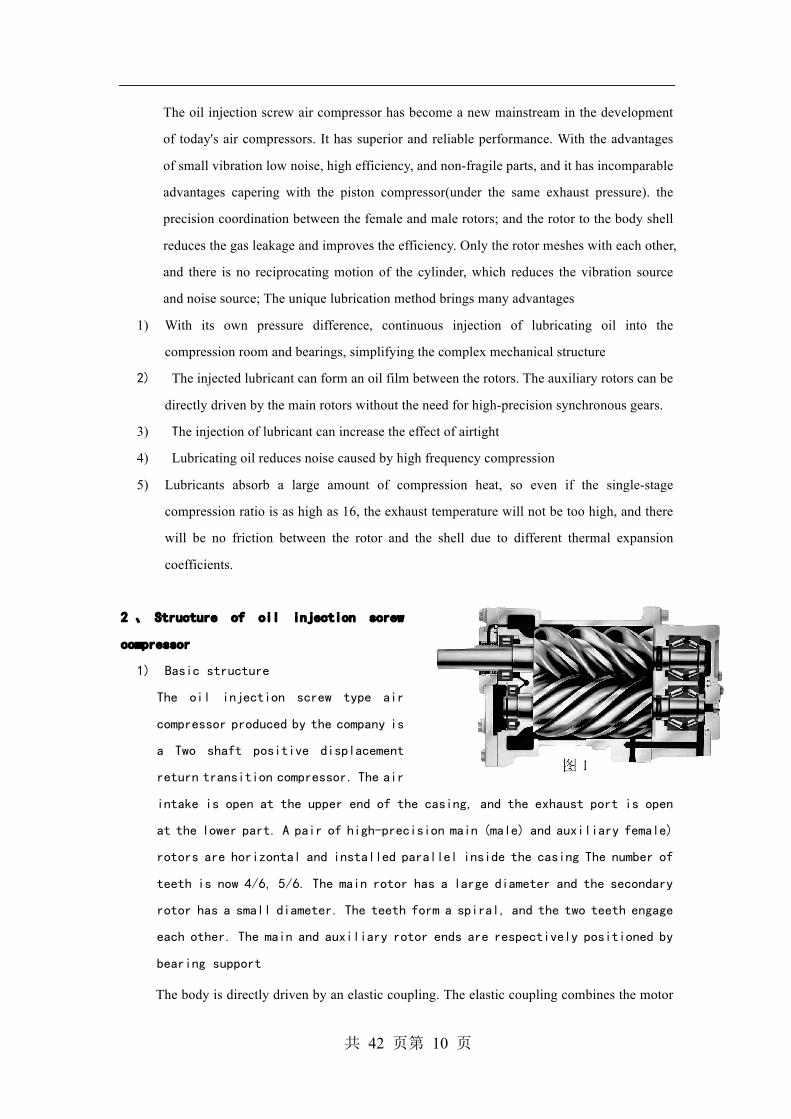
1) Basic structure
The oil injection screw type air
compressor produced by the company is
a Two shaft positive displacement
return transition compressor. The air
intake is open at the upper end of the casing, and the exhaust port is open
at the lower part. A pair of high-precision main (male) and auxiliary female)
rotors are horizontal and installed parallel inside the casing The number of
teeth is now 4/6, 5/6. The main rotor has a large diameter and the secondary
rotor has a small diameter. The teeth form a spiral, and the two teeth engage
each other. The main and auxiliary rotor ends are respectively positioned by
bearing support
The body is directly driven by an elastic coupling. The elastic coupling combines the motor
共 42 页第 11 页
with the main body with a coupling, and then increases the speed of the main rotor through a
set of high-precision growth gears. Belt-driven machine has no growth gear, while it driven
by the two pulleys made in proportion to speed.
2) Meshing
The main rotor is driven by the motor through the coupling, increasing gear
or belt. As the two rotors engage with each other, the main rotor directly
drives the auxiliary rotors to rotate together.The cooling lubricant is
directly sprayed into the meshing part of the rotor by the lower part of the
compressor shell through the nozzle, and mixed with the air to take away the
heat generated by the compression to achieve the cooling effect. At the same
time, an oil film is formed to prevent direct contact between metal and the
gap between the closed rotor and the shell. The lubricating oil injected can
also reduce the noise caused by high-speed compression. Due to the different
exhaust pressure, the weight of the injection oil is about 5-10 times the weight
of the air.
3、Compression principle of screw compressor(take reference to chart(1)-(4))
The screw compressor mainly relies on the main and auxiliary rotors in the airend
for air suction, compression and discharge. Since the air is compressed in the airend
and the air temperature rises, the compressor oil must be injected into the airend.
The oil injected into the compressor's airend has four effects: ①Cooling。②
Sealing。③Lubrication。④Reducing noise。
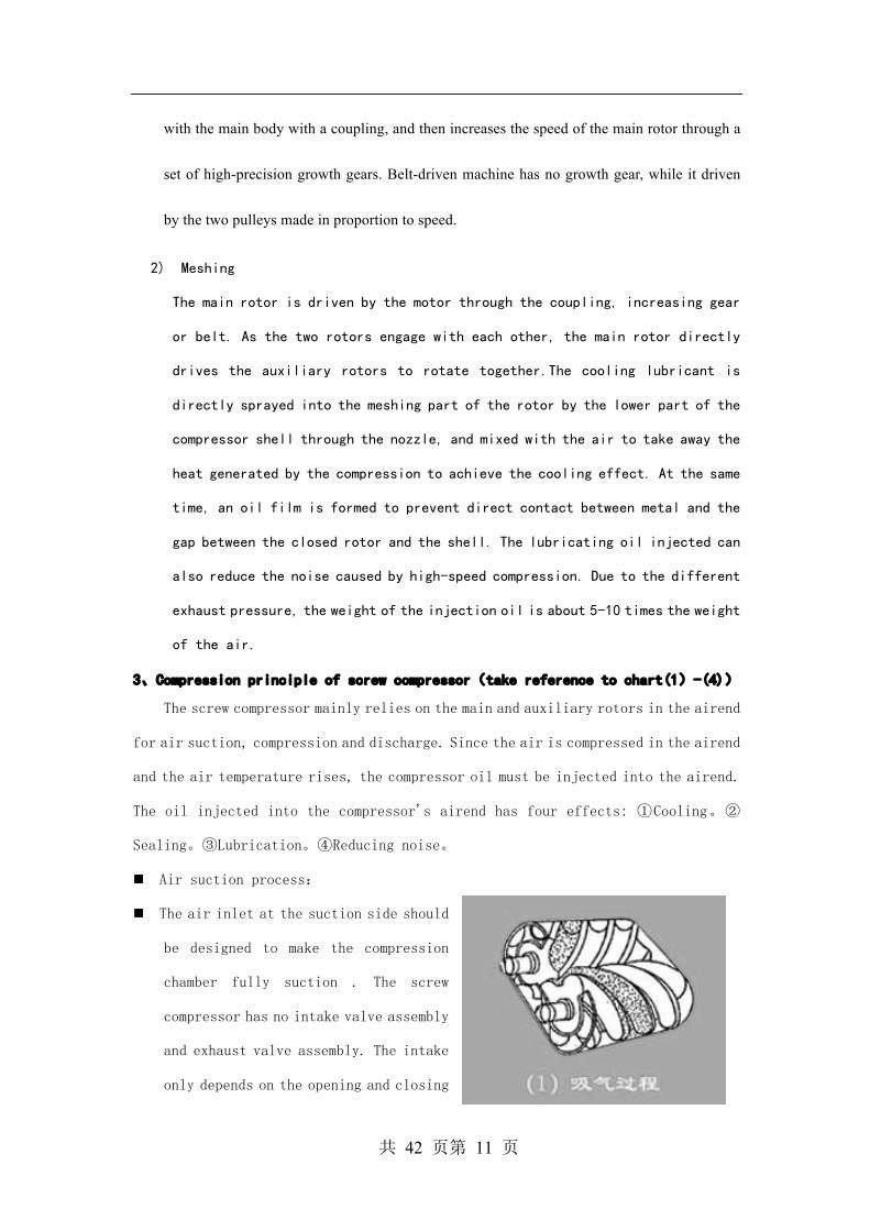
n Air suction process:
n The air inlet at the suction side should
be designed to make the compression
chamber fully suction . The screw
compressor has no intake valve assembly
and exhaust valve assembly. The intake
only depends on the opening and closing
共 42 页第 12 页
of the intake control valve. When the rotor rotates, the tooth groove space of
the main and secondary rotors is the largest when it turns to the opening of
the intake wall. At this time, the tooth groove space of the rotor is connected
to the free space of the air intake, because the air of the tooth groove is in
exhaust. Exhaust, when exhaust ends, The tooth groove is in a vacuum state. When
it turns to the air intake, the outside air is inhaled and flows axially into
the tooth groove of the main and secondary rotors. When the air is filled with
the entire tooth groove, the air intake side of the rotor turns away from the
air intake of the housing, and the air between the teeth is closed. The above
is the "intake process."
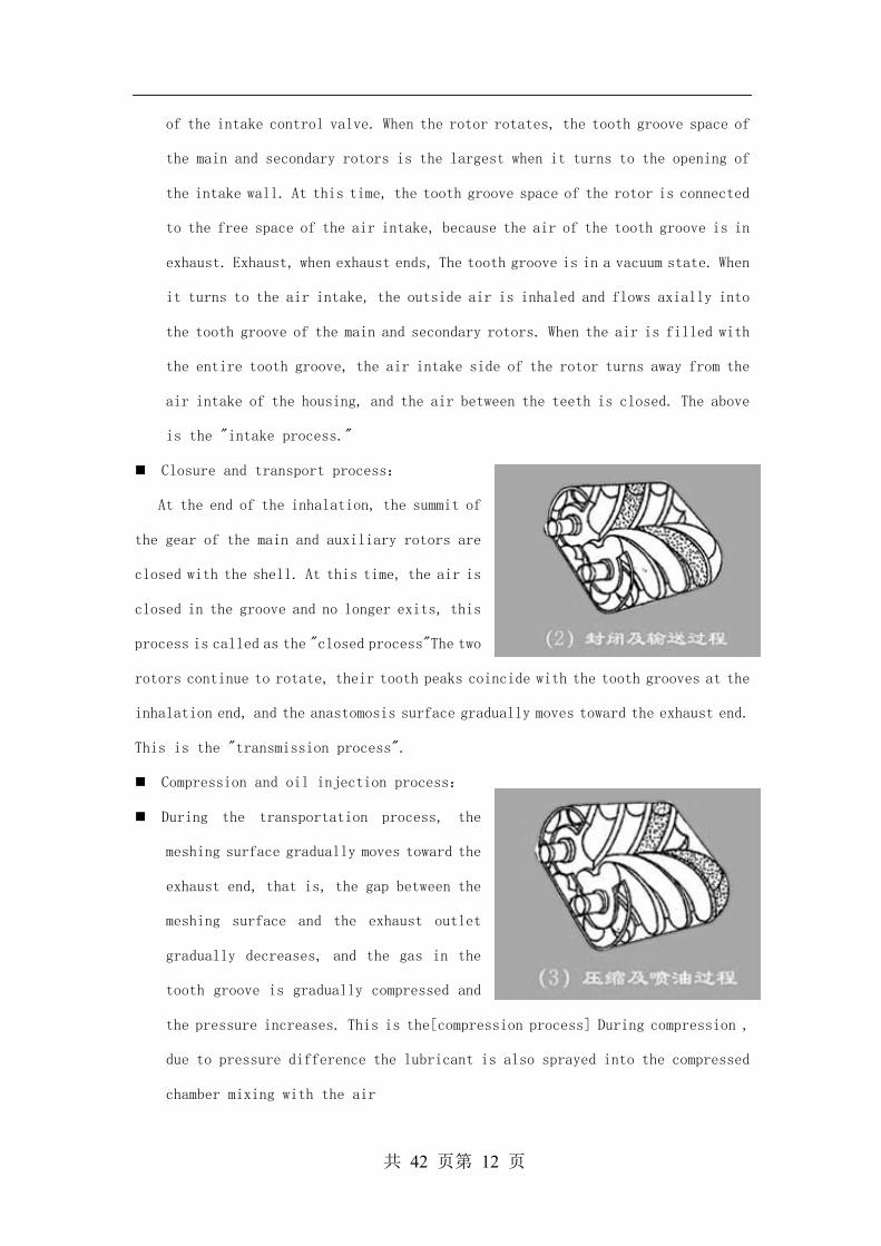
n Closure and transport process:
At the end of the inhalation, the summit of
the gear of the main and auxiliary rotors are
closed with the shell. At this time, the air is
closed in the groove and no longer exits, this
process is called as the "closed process"The two
rotors continue to rotate, their tooth peaks coincide with the tooth grooves at the
inhalation end, and the anastomosis surface gradually moves toward the exhaust end.
This is the "transmission process".
n Compression and oil injection process:
n During the transportation process, the
meshing surface gradually moves toward the
exhaust end, that is, the gap between the
meshing surface and the exhaust outlet
gradually decreases, and the gas in the
tooth groove is gradually compressed and
the pressure increases. This is the[compression process] During compression ,
due to pressure difference the lubricant is also sprayed into the compressed
chamber mixing with the air
共 42 页第 13 页
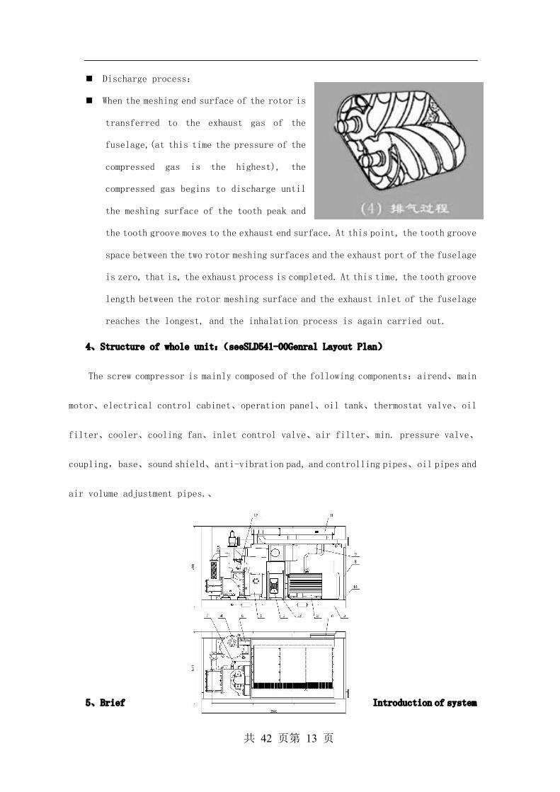
n Discharge process:
n When the meshing end surface of the rotor is
transferred to the exhaust gas of the
fuselage,(at this time the pressure of the
compressed gas is the highest), the
compressed gas begins to discharge until
the meshing surface of the tooth peak and
the tooth groove moves to the exhaust end surface. At this point, the tooth groove
space between the two rotor meshing surfaces and the exhaust port of the fuselage
is zero, that is, the exhaust process is completed. At this time, the tooth groove
length between the rotor meshing surface and the exhaust inlet of the fuselage
reaches the longest, and the inhalation process is again carried out.
4、Structure of whole unit:(seeSLD541-00Genral Layout Plan)
The screw compressor is mainly composed of the following components:airend、main
motor、electrical control cabinet、operation panel、oil tank、thermostat valve、oil
filter、cooler、cooling fan、inlet control valve、air filter、min. pressure valve、
coupling,base、sound shield、anti-vibration pad, and controlling pipes、oil pipes and
air volume adjustment pipes.、
5、Brief Introduction of system
共 42 页第 14 页
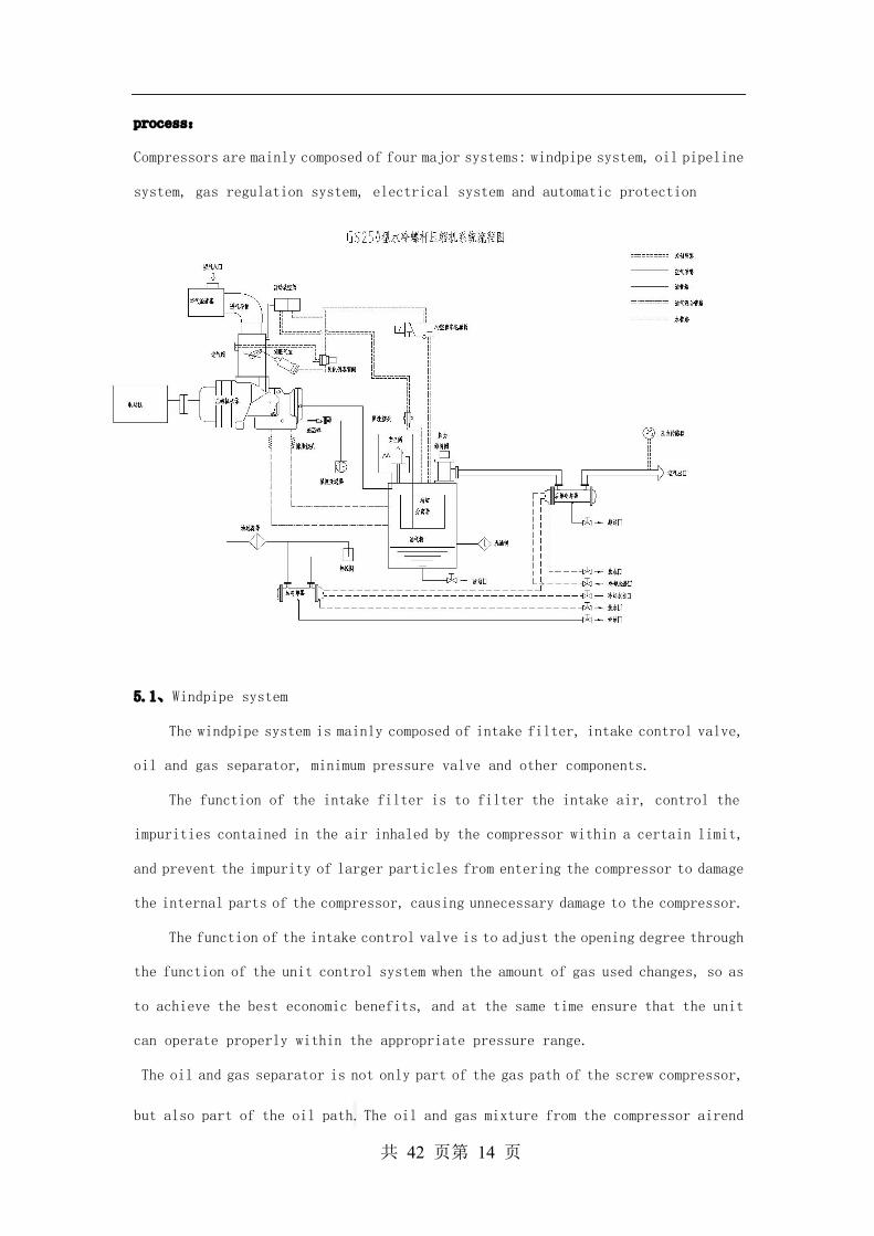
process:
Compressors are mainly composed of four major systems: windpipe system, oil pipeline
system, gas regulation system, electrical system and automatic protection
5.1、Windpipe system
The windpipe system is mainly composed of intake filter, intake control valve,
oil and gas separator, minimum pressure valve and other components.
The function of the intake filter is to filter the intake air, control the
impurities contained in the air inhaled by the compressor within a certain limit,
and prevent the impurity of larger particles from entering the compressor to damage
the internal parts of the compressor, causing unnecessary damage to the compressor.
The function of the intake control valve is to adjust the opening degree through
the function of the unit control system when the amount of gas used changes, so as
to achieve the best economic benefits, and at the same time ensure that the unit
can operate properly within the appropriate pressure range.
The oil and gas separator is not only part of the gas path of the screw compressor,
but also part of the oil path. The oil and gas mixture from the compressor airend

共 42 页第 15 页
is separated by the crude and refined filter of the oil and gas separator, and the
most of the oil is used by the user after the minimum pressure valve. The separated
oil accumulates in the lower part of the oil and gas separator and is recycled into
the oil pipeline system by pressure from the internal pressure of the system. A small
amount of oil deposited at the bottom of the filter core is filtered by the oil and
gas separator filter and recovered to the compressor via the oil-returning pipe
The function of the min. pressure valve: When the valve is fully open without back
pressure, the pressure of about 0.35 MPa in the separation tank is guaranteed to
meet the oil pressure requirements for the normal operation of the unit.In addition,
when the compressor is connected to the gas supply of the main pipe, the minimum
pressure valve can also act as a check valve to prevent the flow of gas back
5.2、Oil pipeline system
(1)、Requirements for lubricating oil for screw compressor:
The lubricating oil should contain anti-rust, anti-oxidation, anti-foam and
other additives. It should be emphasized that different grades of oil can not be
mixed. When a brand of lubricant is selected, it must be replaced for every 3000
H under normal circumstances, If working under dusty or high temperature conditions,
the oil change period is shortened accordingly, If the unit runs less than 1000 H
per year, it must also change oil once a year. When there is sludge deposition,
replace the new oil and remove the old sludge
(2)、Oil pipeline system
Oil pipeline system consists of oil and gas separator, oil cooler, oil filter
and other components。
The function of oil cooler is mainly to cool the circulating lubricant of the
system to ensure the oil temperature needed for the normal operation of the unit.
The oil filter is mainly used to filter out most of the impurities in the oil,
ensure the safe and reliable operation of the compressor, and extend the service
life of the compressor.
There is a back pipe in the oil pipeline system. Its role is to press the residual
lubricant at the bottom of the filter core into the nose in a timely manner so as
共 42 页第 16 页
not to cause too much residual oil, resulting in excessive oil content in the supply
of gas and increased fuel consumption.
In water-cooled screw compressor, the waterway system is an important group to
ensure the normal operation of screw compressor。
Air cooled oil cooler The cooler is an aluminum plate fin structure. The cooling fan forces the air to flow through the fins of the cooler and cools the lubricating
oil in the cooler pipe.。In order to maintain the normal operation of the compressor,
the cooling fins of the cooler should be kept clean, and the maximum ambient
temperature of the compressor should not exceed 45 °C. In daily maintenance, the
surface of the cooler should be washed regularly and, if necessary, rinsed with hot
pressure water not exceeding 3.5 Bar(51 psi)
Water cooled oil cooler: The water-cooled oil cooler uses a shell tube
structure. The lube oil flowing in the shell transmits most of the heat through the
wall of the pipe to the cooling water flowing through the pipe. Unlike air-cooled
models, the lubricant that leaves the cooler does not pass through the thermostat
valve but flows directly through the oil filter into the compression cavity.
Compressor oil temperature is controlled by the water temperature regulator in the
cooling waterway。The water temperature regulator probe senses the temperature of
the lubricant, controls the opening or closing of the regulator valve to regulate
the amount of water flowing through the cooler to achieve the purpose of controlling
the oil temperature, so that the unit operates within the normal temperature range
of 82 ~ 91 °C(180 ~ 195 °F).
5.3、Gas regulation system
The gas adjustment system consists of pressure controller, gas volume control
solenoid valve and air intake control valve
Regulation process as following:
1、Compressor running with load。
2、If gas consumption of the user’s is less than the compressor output, the pressure
of the pipe network increases. When the pressure point pressure reaches the set
discharge pressure, the pressure controller touches the point, the control system
makes the solenoid valve move, the regulation path opens, and the high pressure gas.
Makes the intake control valve close, The crew stopped breathing air. Unit is
operating in unloading state
3、The period of operation in the unloading state is within the time set by the
control system. If the pressure point pressure is reduced to the load pressure set
by the pressure controller, the pressure controller action, the solenoid valve
共 42 页第 17 页
action, the regulated gas path closure, the intake control valve is opened, and the
compressor load is operated. The unit resumes the supply.
4、If the operation time in the unloading state exceeds the set time, the unit will
automatically stop and be in the shutdown waiting state.;Once the pressure point
pressure drops to the load pressure, the unit will start automatically, and the
compressor will resume operation and supply of gas.
When the compressor is in the unloading state, its shaft power is only 20 to 30 %
of the load state, which greatly saves energy.
5.4 Electrical and automatic protection systems
The electric system is a control system that realizes the starting, stopping,
parameter display and automatic protection of the unit. The system mainly includes
motor, starting cabinet, controller, contactor, Transformer, terminal and cable,
etc.
Note:The units are shipped with relevant data. To avoid accidental operation,
please refer to the random attached electrical diagram when repairing and
maintaining the electrical system.。
The standard drive motor is IEC closed, the protection grade IP54, and the
maximum ambient temperature used is 40 °C(104 °F). This standard motor is not
suitable for salty, corrosive, dirty, wet and explosive situations.
This series of standard compression units is equipped with energy-saving
controller.
Warning:
High pressure electricity will cause serious casualties. Please cut off the power
before performing electrical repairs or opening the electrical control box
共 42 页第 18 页
Chapter III Installation and Acceptance
1..Summary
Check if there has any damage caused by transportation。If damage is found, the
carrier may be required to sign the shipping document and report the damage。If it
was not discovered at the time, but was found to be damaged afterwards, it was
concealed damage. Please inform the carrier within 15 days of receipt of the goods
and request the carrier to make a damage report. A detailed report is important for
the handling of the loss(claim)
Check the compressor nameplate to see if the machine is the type and
specification you ordered and if the parts is included. Check the oil and gas
separator and safety valve at the same time to confirm that the design or set pressure
is correct
2. Overall handling
The side or end of the base of the unit provides forklift holes. When using
forklift for handling, care should be taken to evenly distribute the weight of the
machine on the forklift.; If lifting equipment is used, please note that the chain
hook is only applied to the bottom frame of the compressor. Do not use other parts
to lift
“Note”
Incorrect lifting compressor will damage the machine or cause personal
injury. Follow good handling practices and safety procedures when
moving compressors。
3.Installation and location
Place the compressor in a clean, well lit and ventilated environment. The
foundation should be firm and flat. The entire base should be closely fitted to
the horizontal surface of the foundation and, if necessary, be covered with a hard
rubber pad, but be careful not to use wooden pods. For safety and maintenance and
daily inspection, there must be enough space around the machine(at least 1 meter
of space is reserved around and at the top of the compressor)
The operating ambient temperature of the compressor must not exceed
45 °C(113 °F). Otherwise the compressor will overheat and stop, not less than 0 °C
otherwise the condensed water will freeze The space size and shape of the compressor
room must be carefully considered so that the hot air emitted by the cooling fan
does not circulate in the engine room and cause the working environment temperature

共 42 页第 19 页
to rise In principle, all models in this series are for indoor installation. They
can also be installed outdoors. The hood is waterproof rather than sealed. Rain,
snow and ice should be avoided.
The foundation should be built on hard soil, and the base plane will be grinded
horizontally to avoid vibration and noise of the compressor. If air compressor
installed upstairs, must be good anti-vibration treatment to prevent vibration into
the downstairs or resonance. The vibration generated by the screw air compressor
is very small, so it does not need to make the basis. The ground set up is flat and
can not be a soft soil. If a rubber shock absorber 5 to 15 mm thick is added, the
effect is better.
The air compressor is a heating equipment, especially an air-cooled type. The
ventilation of the factory building is very important.。It is necessary to
install an exhaust equipment according to the outside wind. The amount
of air drawn must be greater than the amount of air drawn by the compressor
circulation fan or cooling fan, and the area of the cooling air inlet must
be sufficient. A hood can also be installed at the outlet of the exhaust fan
at the top of the air compressor to remove the hot air discharged by the air
compressor from the air duct to maintain room temperature between 5 to 40 °C.
When the exhaust pipe is used, space must be reserved for the installation of canvas
movable joints for maintenance(such as cleaning the cooler, there can be enough
space to remove the compressor cover and other parts).

共 42 页第 20 页
4、Attention to Piping, Foundation and Cooling Systems
“Warning” Compressors can not work under 0 °C(35 °F) or above the maximum
operating temperature limit。
Do not place the compressor in a high-temperature exhaust gas environment that
may be inhaled from other compressors or heat load equipment .Do not obstruct the
cooling and ventilation of the air-cooled compressor, it should be directed outdoors,
so as not to cause excessive ambient temperature in the compressor room. If the
compressor room is poorly ventilated, it may cause the machine to shut down at high
temperatures. Do not place compressors in the basement or in poorly ventilated areas.
Control the operating temperature of the compressor and monitor the lubricating oil
of the compressor, taking into account the possibility of water pollution to the
oil
“Note” Compressors need enough clean air to work.
共 42 页第 21 页
“Note”
Removing or changing the sound shield can create high noise levels
that can be harmful to human health。
This series of compressors operate smoothly, basically no vibration, can be
placed naturally without the need for foot connection However, the compressor may
be bolted to avoid damage to the pipes or electrical connections due to displacement
in the event of a collision, if required by the user. Please note that the bolts
should not be too tight to prevent the bolts from causing distortion of the bottom
frame of the machine and causing oil coolers, pipes and storage tanks to crack and
break。
“Warning” Do not install or expose compressors to toxic, volatile or corrosive
gases, nor store substances of similar nature in their vicinity. This will
cause serious casualties and property losses.
.Pipe connection
Do not use lead or tin welding in connections to pipes or connections. Lead or
tin welding material is low in strength and does not withstand high temperatures.
Its melting point is only 182 °C(360 °F), so do not confuse it with silver and copper
welding. Also be careful not to use plastics, PVC, ABS pipes or rubber hoses in
compressed air piping systems.
Care must be taken not to install rusty pipes on the compressor and the pipes
should be unbent and twisted to the proper position. In order to avoid the impact
of hot expansion and cooling on the system, install some flexible expansion joints
or hoses in the pipeline system as necessary. Pipes shall be supported and secured
independently to reduce vibration and prevent expansion and deformation. In any case,
the size of the pipe shall not be less than the connection size of the discharge
pipe of the compressor.
Clean air is vital to the compressor. Air filters are essential, and air sources
that provide clean air should be selected. If outdoor air sources are used, all pipes
must be short and straight. To properly set up the pipeline and avoid vibration.
Pipe diameter should not be less than the size of the air intake valve. For the long
pipeline, the diameter of the pipeline should also be increased. Pipe shall also
be leakproof and shall be absolutely clean after installation.
5. Installation of safety facilities
5.1. Safety valve(pressure release valve)
The safety valve is a suitable size, and the pressure relief device used to
protect the system it is set up at the factory. It can not be changed its pressure
setting or blocked the valve(generally for a compression unit with a rated pressure
of 7 Bar, the opening pressure of the safety valve is set to 9Bar; For a compression
共 42 页第 22 页
unit with a rated pressure of 8 Bar, the opening pressure of the relief valve is
set to 10 Bar; For a compression unit with a rated pressure of 10 Bar, the opening
pressure of the relief valve is set to 12 Bar). Only safety valve manufacturers or
qualified agents can perform this work
The relief valve should be located prior to the potential plug point, including
the cut-off valve, heat exchanger and exhaust silencer(but not limited to this).
In theory, the relief valve should be directly connected to the pressure tube or
container, rather than connecting them to the pipe
“Warning” The standard GB (or ASME) pressure vessel is not allowed to change, weld,
repair or reprocess. Neither to be used under conditions that exceed the nameplate
rating, otherwise it will affect the insurance terms and cause serious casualties
and property losses.
5.2. Protection shield
All mechanical movements are dangerous to varying degrees, so protective
shields should be provided. This series of units are completely in accordance with
the national and industry standards installed the necessary protection facilities,
users should make regularly inspection and maintenance, can not be arbitrarily
changed or demolition
5.3. Manual emptying valve and cut-off valve
The purpose of installing manual emptying valves is to drain air from the
compressor and its exhaust pipes into the atmosphere,When the system tank is only
used with a single compressor, the release valve can be installed on the tank。
If a cut-off valve is installed in the system, the manual release valve should be
installed upstream of the stop valve. This configuration ensures that personnel and
equipment are safe during maintenance
If only to isolate the compressor from the system for repair, please note that
the non-return valve is not used instead of the cut-off valve
“Warning” Manual emptying valves must be opened before repairing the machine, emptying
the pressure in the compressor and in the system. Neglect on the system relief may
result in serious personal injury, death and property damage.
6. Electrical installation
Before installation, check if that the power supply, power lines and transformer
capacity match, and that appropriate fuses or circuit breakers are provided during
installation. Unbalance between voltage phases should be limited to 5 % to prevent
over-current due to low voltage. The installation of motors, wiring, cables and all
electrical components must be in accordance with relevant national electrical
standards and local codes. Only qualified electricians can perform the above tasks.
Compressor must be well grounded, see electrical wiring chart
共 42 页第 23 页
7. Drainage(water-cooled)
Make sure the connection to the water supply and drainage pipes is clear The
configured waterway system shall at least have the same waterway diameter as the
compression unit. Drainage equipment should be easy to install and connect. And to
meet the local drainage standards and compressor itself requirements. Make sure that
the connection to the drain pipe is correct.
“Note”: The water regulator is located on the drainage pipe.。
“Warning” Removal or unpainted security signs can result in a state of no warning, which
may result in personal injury or property loss. Warning signs should be highlighted
and placed in a well-lit and eye-catching position. They should also be legible and
should not be moved with warning signs and other accompanying instructions
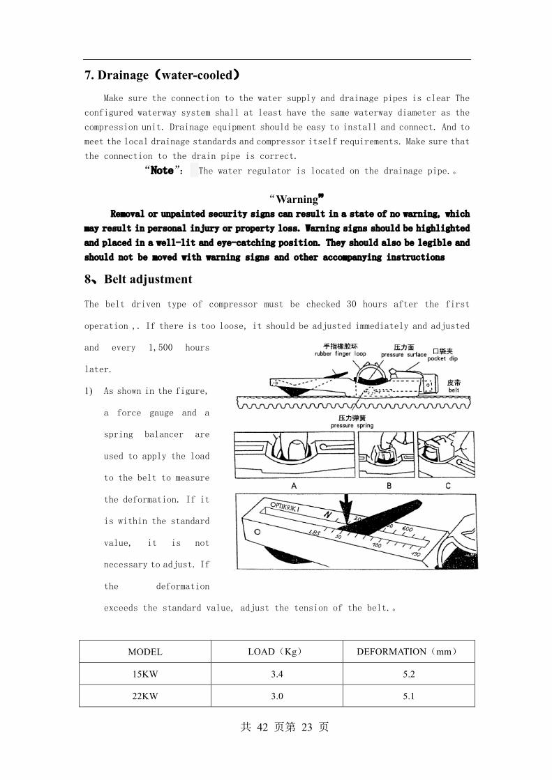
8、Belt adjustment
The belt driven type of compressor must be checked 30 hours after the first
operation ,. If there is too loose, it should be adjusted immediately and adjusted
and every 1,500 hours
later.
1) As shown in the figure,
a force gauge and a
spring balancer are
used to apply the load
to the belt to measure
the deformation. If it
is within the standard
value, it is not
necessary to adjust. If
the deformation
exceeds the standard value, adjust the tension of the belt.。
MODEL LOAD(Kg) DEFORMATION(mm)
15KW 3.4 5.2
22KW 3.0 5.1
共 42 页第 24 页
2) When adjusting the tension of the belt, first relax the tight screw behind the
motor seat, and then adjust the first two screws of the motor base to adjust
the belt tension, and after measuring by the tension meter ,tighten the fixed
screw on the motor.
3) If you want to replace the belt, all the belts must be replaced together. You
must not only replace one belt, otherwise the tension will be unbalanced,
influencing the useful life of the belt
4) 。Do not splash oil on the belt wheel when adjusting or replacing
5) After adjustment, the motor wheel and the fly wheel must be in the same line,
otherwise the belt is prone to wear and produce different sounds
Chapter IV Operating Procedures
1、New machine test
1) Connect the power cord and the ground cable to test whether the voltage is correct
and whether the three-phase voltage is balanced
2) Loosen the transportation fixed bolt of the shock table on the base
――――Note――――
When moving the machine, it is necessary to re-tighten the transport fixing bolt
to prevent damage to the shock cushion such as tilt, vibration, or cause the shock
cushion to shift, causing the expansion joint to break
3) Check whether the oil level in the oil separator tank is between the two lines
of the oil glass.
4) 1.4、If it takes a long time to deliver the test, add about 0.5 liters of lubricant
from the intake valve and turn the air compressor by hand to prevent the loss
of oil and burn damage Please pay special attention to not letting any materials
fall into the compression body to avoid damage to the compressor.
――――Note――――
No power to the compressor at this time
5) Power to compressor controller

共 42 页第 25 页
――――Note――――
If the phase of the power supply does not match, the electric fault light
will be on
6) Steering test: Press the "ON" key and the compressor rotates. Press
the "Emergency Stop Button" immediately to confirm the compressor's
steering. Please refer to the arrow on the compressed body for correct steering. In the case of a steering error, replace any two phases in
the power lines R, S, and T. Cooling fans also need to pay attention
to steering
――――Note――――
When overhauling electrical equipment, it is necessary to cut off the
power supply and prohibit electric operation
Although the compressor has been tested during the production process,
the steering test is still an important step for the new machine test
――――Note――――
Reverse phase protection is to detect the phase of the power supply. After
the motor is overhauled, it must be retested for steering.
7) Start up: Press "ON" to start the compressor
――――Note――――
This machine is fully automatic operation type, Y/△pressure-relief
start about 8 seconds, after switch it delays 3 seconds, the air intake
valve starts to move
8) Observe whether the instrument and indicator light are normal, if there
is abnormal sound, vibration, leakage, immediately press the
"Emergency Stop button", stop and repair
9) Stop: Press “OFF”,the compressor stops
――――Note―――
When the "OFF" key is pressed, the exhaust valve of the compressor is
discharged and unloaded, the timing relay starts to time, and the motor
stops within about 15 seconds.
――――Note――――
Under normal circumstances do not use the "emergency stop button” to stop
the machine
共 42 页第 26 页
2、Daily check before start up the machine
Daily pre-boot inspection is a necessary job for the compressor to
run normally. Please do it.。
1) Water drain of the oil separator tank:Slowly open the oil discharge
valve of the oil and gas barrel and drain the condensation water during
the shutdown until there is a lubricating oil flow.
――――Note――――
Make sure there is no pressure in the tank before opening the valve
2) Oil level check:Add to the level between the upper and lower limits
of the oil gauge if necessary
――――Note――――
Please use UINCOL special oil, do not mix other brand or different brands
of lube oil
Make sure there is no pressure in the system when adding lubricating oil
The oil level should be observed ten minutes after the shutdown. During
operation, the oil level may be slightly lower than the oil level at the
shutdown.
3) Other equipments preparation:power supply,cooling water tower、
water pump、open the outlet valve, start air dryer
4) Start up the compressor.
3、Operational considerations
1、Stop immediately when there is noise and abnormal vibration in operation
2、There has pressure in running lines and containers, do not to loosen
pipe screws and to open unnecessary valves
3、In the long-term operation, if the oil on the oil gauge is found to
be invisible and the oil temperature gradually rises, it should be
stopped immediately. Observation of oil level after 10 minutes of
downtime, and replenishment of lubricants when pressure is not present
in the system
4、There will be condensation water in the rear cooler and cyclone
separator. After the power is shut down every day, the plug under the
water separator should be released and the condensation water should
be released(after confirming that the system has no pressure).
共 42 页第 27 页
Otherwise, the water will be brought to the system when rebooting
5、Check the meter every 2 hours during operation to record voltage,
current, pressure, exhaust temperature, oil level, etc. for future
maintenance reference.
四、Treatment of long-term downtime
During long-term downtime, be careful to follow the following
methods, especially in high humidity seasons or areas
1、More than 3 weeks of downtime
(1)Electrical equipment, such as motor control panels, shall be wrapped
in plastic or oil paper to prevent moisture intrusion
(2)Exhaust completely the water from the oil cooler, the water in the
rear cooler
(3)If there is any fault, it should be resolved first to facilitate future
use
(4)After a few days, discharge the condensation water from the oil
separator tank, oil coolers, and post-coolers
2、More than 2months of downtime
(1)Seal all openings to prevent moisture, dust from entering.。
(2)Wrap up safety valves, control plates, etc. with oil or similar paper
to prevent rust
(3)Replace the oil with new oil before decommissioning, and run for
thirty minutes. Two or three days later, drain the condensing water from
the oil separator tank and oil coolers.
(4)Drain out completely the cooling water。
(5)Move machines as far as possible to less dust and dry places for
storage
3、Reboot program
(1)Remove plastic or oil paper from the platform
(2)Measurement of motor insulation should be at least 1MΩ
(3)Other procedures, such as test steps。

共 42 页第 28 页
CHAPTER V Maintenance
1. Preparations before maintenance
Good maintenance is the key to ensure the normal operation and long
service life of the unit. Therefore, the maintenance rules of the screw
compression unit must be carefully executed. Before proceeding with
maintenance, please read chapter 1 of this manual safety rules carefully
and prepare at least the following:
1.1. Cut the main power and put a sign on the power switch
1.2. Close the cut-off valve to the air supply system to prevent
compressed air from flowing back to the overhauled part. Never rely
on a one-way valve to isolate the supply system
1.3. Open the manual emptying valve, drain the pressure in the system
and keep the emptying valve open
1.4. For water-cooled machines, the water supply system must be shut down
to release pressure from the water line
1.5. Make sure the compressor unit is cooled to prevent burns
1.6. Wipe the surface oil marks, water tracks to prevent slipping
“Warning”
Don't assume that the machine is out of service and that the
machine's automatic control system will start the compressor at any
time
Poor maintenance not only affects the normal operation of the unit,
but also may affect the safety of the operator
Do not remove nuts, fuel plugs and other parts while the compressor
is running or under pressure
Do not use contingency solvents such as gasoline or kerosene to clean
air filters or other parts. Safe solvent should be used according to
instructions
2.Maintenance of screw compressor
2.1.1Requirements to the lubricant
The lubricating oil should contain anti-rust, antioxidant,
共 42 页第 29 页
anti-bubble and other additives
Our company uses Unicol screw compressor special oil. Unicol screw
compressor special oil, life 3000 H
Different grades of lube oil can not be mixed. When a certain brand
of lubricant is selected, it must be replaced after each 3000 H under
normal circumstances. If working in a multi-layer or high temperature
environment, the oil exchange cycle is shortened accordingly. If the
compressor runs less than 1000 H per year, it must also change oil once
a year
压缩机正常运转情况下油位不能超过油标的 2/3,初次加油可以多加一些。
“Danger”
High temperature and high pressure lubricants can cause serious burns
and even casualties. Do not open oil plugs during operation or pressure
in the machine. If you want to refuel, make sure the device is turned off
first, and the power of the device is convinced that the device has been
cut off, and the device has no possibility to start automatically.
2.1.2 Drainage and replacement of lubricant
Condensed water at the bottom of the oil and gas separator tank should
be periodically eliminated. When the moisture content of the lubricant
exceeds 200 PPM, the lubricant is heavily emulsified, resulting in damage
to the airend and bearings, and the lubricant needs to be replaced. Do
not mix different types or brands of oils when changing oil. Otherwise,
your warranty will be invalidated. If you really need to use other types
of lubricants due to special circumstances, please contact the Unicol
Agent or Unicol Service Department
2.1.3 Factors affecting the life of lubricants
1) Abnormal high operating temperature
共 42 页第 30 页
2) Pollution:
a) Other type or brand of lubricant
b) Strong oxidizing substances such as
sour
sulphur
chloride
Nitrogen oxide
Welding exhaust gas
ozone
c) Ammonia
d) Solvant smoke
e) Air dust
f) High temperature
2.2 Oil Filter
After 500 hours of operation of the new machine, the element of the oil filter
Should be replaced. After that oil filter should be replaced whenever the following
situations occur. The replacement procedure is described in Section 5 of this Chapter,
part replacement and adjustment procedures. When changing the filter element it is
necessary to stop the operation and carefully remove dirt and oil from the outside
to prevent impurities from entering the lubrication system as far as possible.
Filter indicator lit at normal operating temperature with filter pressure
difference exceeding 19 PSI;
Every 100 hours of running time;
When changing the lubricant;
When it is unqualified in sample test
“Note”
The indicator for the filter may be lit on a cold morning after the
compressor is started. This is due to the pressure difference caused by the low
mobility of the lubricant. Please monitor the indicator after the compressor is
operating at normal temperature.
If there are indications that insoluble sediment has formed on
the filter core of the oil filter, which indicates that the

共 42 页第 31 页
lubricating oil of the compressor is no longer working properly,
it must be replaced immediately
2.3Safety Valve
If there is a dirty or plug , it will cause the safety valve not to open or
can not be automatically closed after opening。Failure to open the safety valve
will cause it to lose the function of the protective pressure system and make the
safety of the unit unsafe. Failure to automatically close the safety valve will
result in an accident that a large number of oil ejected from the oil separator tank,
and resulting in property losses. Weekly downtime should be used to check the state
of the relief valve.
2.4The second time of oil-return pipe
The role of the secondary oil return pipeline is to lead the oil accumulated
inside the oil separator filter back to the low pressure cavity of the compressor,
where the throttle hole is used to ensure the return of oil stability.。If there
is a serious blockage in the secondary return pipeline(mainly in the throttle holes
and filters), the exhaust gas will be too oily。Check the secondary return line at
specified times and clean the throttle holes and filters
In daily maintenance, the throttle hole should be cleaned under the following
circumstance:
Can't see the oil flowing through the oil back window;
Found that the oil content was too high;
Every time to replace the lubricant;
Once every year.
2.5 Oil cooler
When there has oil, grease, dust, and dirt accumulate on the surface of the cooler,
the heat transfer effect of the cooler is weakened, and eventually the exhaust
temperature will rise too high
Every two months, use vacuum cleaners, cleaning fluids or compressed air(usually
共 42 页第 32 页
not higher than 3.5 bar) to clean the outer surface of the cooler
2.6 空气滤清器 Air filter
Air filters should be checked daily
Clean the dust-collection bag and clean the dust-collection cover every day. In
dusty environments, cleaning should be done more frequently. If the environment is
hazardous, it is recommended that the compressor air intake be directed to a place
where there is a clean air source outside.
Whenever the air filter vacuum switch moves and the indicator light is on, the
filter core should be maintained; For every 500 hours or three months of work,
the air filter should be checked for damage and to see if the air intake system is
strictly sealed; 2000 hours or one year, both cases, whoever appears first, should
replace the filter core;Replace the safety filter at the same time when changing
the main filter core. Safety filters do not need to be maintained during use.
The procedure for the maintenance or replacement of the filter elements can be
found in section 4 of this chapter “the replacement and adjustment of spare parts”
Check if the downstream side of the filter core is dirty every time the air filter
is maintained. If so, the reasons must be identified and resolved. To ensure that
the airtight between the air filter and the compression hole, thread connection,
flange connection, leather pipe connection is absolutely reliable
2.7Intake valve
There is an O-ring sealed piston propulsion system in the intake valve. To ensure
its normal operation, it is necessary to regularly inject unicol lubricant into the
rear of the intake valve.
2.8 Oil –gas separator
The element is an integral structure that condenses the oil mist to form oil
droplets on its surface, drops into the bottom of the separator, and is recycled
by the back pipe and flows back into the compression cavity. The separator must be
carefully handled to avoid damage. Once the core of the separator is deformed by
共 42 页第 33 页
impact, even a small amount of indentation will affect the separation efficiency,
resulting in an excessive amount of oil in the compressor. Even a tiny hole in the
component will cause a very high amount of oil.
Under normal circumstances, if the air filter and oil filter are properly
maintained, the oil and gas separator filter core does not need to be replaced
periodically
The element of oil separator should be replaced under the following
circumstance:
The separator pressure difference indicator gives an indication that the front
and rear pressure difference exceeds 10 PSI
The amount of oil in the compressed air is still too high when the oil level
is determined to be normal, the loading and unloading are normal, and the return
system is normal.
Every 4000 hours
2.9 Hose
For every 4,000 hours or half a year, the flexible the intake hose, lubricant
pipe and control pipe must be checked and replaced if necessary
2.10Compressor shaft seal
Compressor shaft seal belongs to wear type parts, sooner or later must be
replaced. The replacement of shaft seals can only be successful if they are equipped
with specialized tools and have a complete understanding of the installation process
and operating procedures. If you decide to do it yourself, please request a complete diagram, workmanship and maintenance instructions from either the unicol agent or
unicol
“Note”: When removing a defective shaft seal part, do not destroy it. Pay attention to the damaged part of the seal to understand the cause of the damage
3. Maintenance of motor
3.1 Use of conditions of Unicol special motor:
Environmental temperature ≤40℃
共 42 页第 34 页
Frequency 50Hz
Voltage 380V
Working mode S1
IP/Isl. class IP55/F
3.2Operation of Unicol special compressor motor
3.2.1When the voltage and frequency of the special motor for the
compressor of Unicol maintain the specified values on the nameplate,
the motor can continue to operate at the power rating multiplied by
the power of the service coefficient。When the frequency deviation of
the power supply exceeds 1 % of the nameplate value or the voltage
deviation exceeds 5 %, the motor can not guarantee continuous output
of this power.
3.2.2 When the three-phase imbalance of power supply does not exceed
1 %, the special motor of Unicol compressor can operate well.
3.2.3 There shall be no intermittent or abnormal sound or vibration
during the operation of unloaded or loaded motor.
3.3Maintenance and repair of Unicol special compressor motor
3.3.1 The environment should always keep dry, motor surface should
keep clean, air inlet should not be hindered by dust, fiber,
etc..
3.3.2 If the operating environment is wet or after a long period of
downtime, heat should be used to remove moisture when starting
3.3.3 When the thermal relay is in action, the source of the fault
should be checked and the fault eliminated before it can be put
into operation
3.3.4 The bearings shall be well lubricated during the operation of
the motor. General motor running around 2000 H should be
supplemented or replacement grease(closed bearings do not need

共 42 页第 35 页
to replace grease during the service life). If it is found that
the bearing is overheated or the grease has deteriorated, the
lubrication grease should be replaced in time. The grease
number is UNIREXN2. See the grease nameplate on the motor for
details.
3.3.5When the bearing life is over, the vibration and noise of the
motor during operation will increase significantly. At this
time, the bearing should be replaced.
3.3.6 If the motor fails, please contact the unicol service
department or agent
4.Maintenance Plan
The following table is the maintenance schedule for the screw compressor.
The daily maintenance plan for the compressor is formulated. Maintenance
of the corresponding items in the table is required regardless of whether
either of the working hours or the maintenance cycle is reached first
Table of maintenance schedule for Unicol Screw compressor
Working
hours
Period Item Content
10 Every
day
Air filter Clean the dust bag. Maintains the filter
if the alarm light is flashing
Oil separator Release the accumulated condensate before
booting.
50 Every
week
Safety valve Check for blockage or other damage
Oil filter Change of element for the first 50 hours
after the new machine is operational
Secondary
oil-return
pipeline
The first 50 hours after the new machine
is running, cleaning the throttle holes
and filters on the secondary return
pipeline
filter Release the water of the filter cup
100 Half
month
Oil and rear
cooler
Clean the surface
500 3months Oil filter Replace the element in primary use

共 42 页第 36 页
Air filter To check and maintain the element to
ensure the seal of the inlet system
1000 Half a
year
Oil filter Maintain and replace element
2000 One year
Secondary
oil-return pipe Clean the throttle holes and filters
Lubricant Take sample to analyze and replace if
necessary
Air filter Replace element
Upon request
Oil separator
element
Replace when oil separator gauge readings
exceed 10 PSI or are damaged
Oil filter Replace when the pressure difference
gauge reading exceeding 19psi
Chapter VI Diagnosis and troubleshooting of common faults
1. Summary
There are many reasons for the failure of the unit. A failure is usually not
caused by a part or a factor. Therefore, the diagnosis and elimination of the failure
are often difficult.
The fault diagnosis and troubleshooting table is based on a wide range of tests
in practical applications and manufacturers. The table points out the common
failures that may occur in the unit and the general reasons for the above failures,
as well as how to eliminate them, but it is impossible to list all the failures and
troubleshooting methods.
A comprehensive and systematic analysis of the possible causes of failure should
be undertaken prior to repair or replacement of components. If you encounter problems,
you should carefully observe, find out the faults, identify the reasons, and then
carry out the necessary maintenance work to avoid unnecessary damage to the unit
Here are a few things to keep in mind:
a. Check for loose wires;
b. Check for damaged lines; c. Check for damage to components due to overheating or circuit
short-circuit(usually with discoloration or scorching)
After checking according to the recommended method, if the failure can not be
solved, please consult the nearest Unicol agent or directly to the Unicol after-sales
service department.
2. Fault diagnosis and troubleshooting table
Fault Phenomenon and
Possible Causes Troubleshooting
共 42 页第 37 页
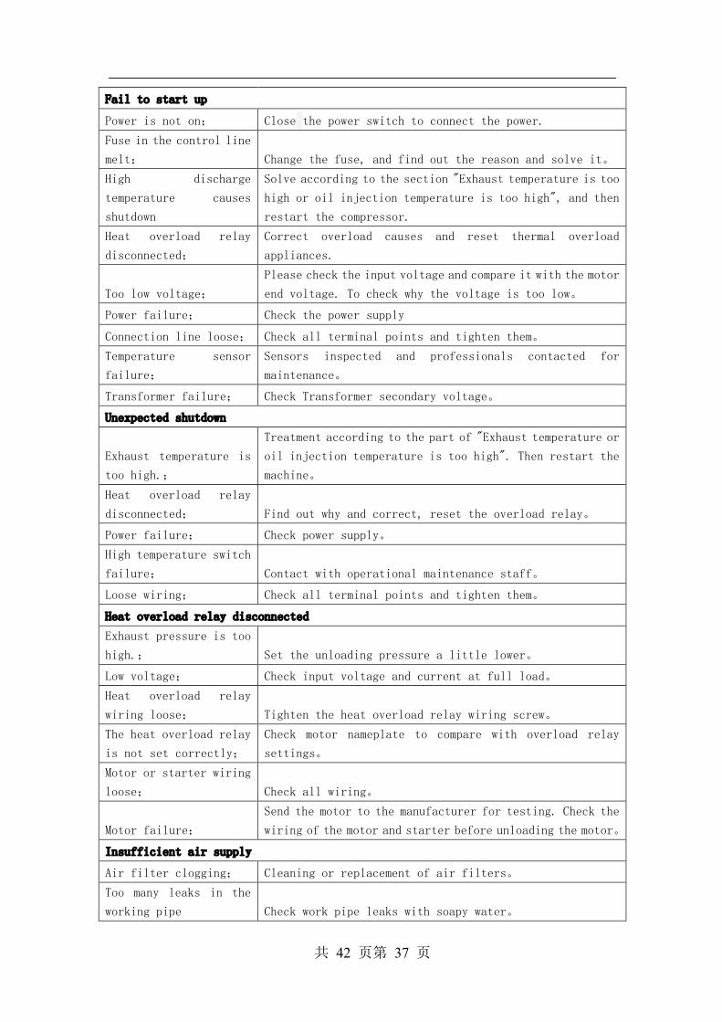
Fail to start up
Power is not on; Close the power switch to connect the power. Fuse in the control line
melt; Change the fuse, and find out the reason and solve it。 High discharge
temperature causes
shutdown
Solve according to the section "Exhaust temperature is too
high or oil injection temperature is too high", and then
restart the compressor. Heat overload relay
disconnected;
Correct overload causes and reset thermal overload
appliances.
Too low voltage;
Please check the input voltage and compare it with the motor
end voltage. To check why the voltage is too low。
Power failure; Check the power supply
Connection line loose; Check all terminal points and tighten them。 Temperature sensor
failure;
Sensors inspected and professionals contacted for
maintenance。
Transformer failure; Check Transformer secondary voltage。
Unexpected shutdown
Exhaust temperature is
too high.;
Treatment according to the part of "Exhaust temperature or
oil injection temperature is too high". Then restart the
machine。 Heat overload relay
disconnected; Find out why and correct, reset the overload relay。
Power failure; Check power supply。 High temperature switch
failure; Contact with operational maintenance staff。
Loose wiring; Check all terminal points and tighten them。
Heat overload relay disconnected Exhaust pressure is too
high.; Set the unloading pressure a little lower。
Low voltage; Check input voltage and current at full load。 Heat overload relay
wiring loose; Tighten the heat overload relay wiring screw。 The heat overload relay
is not set correctly;
Check motor nameplate to compare with overload relay
settings。 Motor or starter wiring
loose; Check all wiring。
Motor failure;
Send the motor to the manufacturer for testing. Check the
wiring of the motor and starter before unloading the motor。
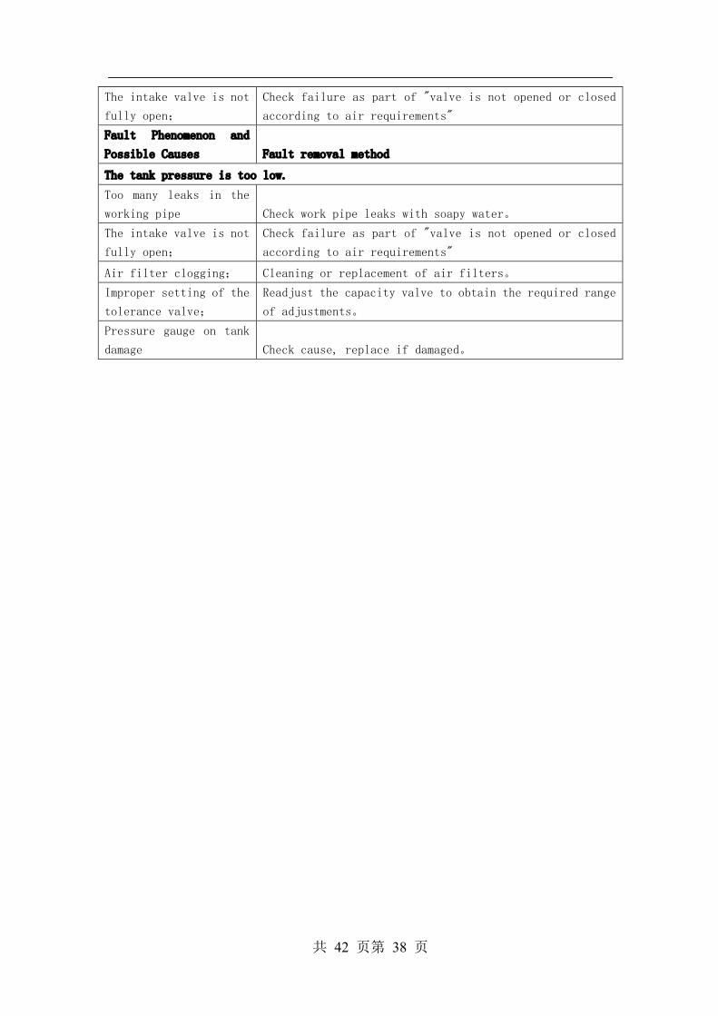
Insufficient air supply
Air filter clogging; Cleaning or replacement of air filters。
Too many leaks in the
working pipe Check work pipe leaks with soapy water。
共 42 页第 38 页
The intake valve is not
fully open;
Check failure as part of "valve is not opened or closed
according to air requirements" Fault Phenomenon and
Possible Causes Fault removal method
The tank pressure is too low.
Too many leaks in the
working pipe Check work pipe leaks with soapy water。 The intake valve is not
fully open;
Check failure as part of "valve is not opened or closed
according to air requirements"
Air filter clogging; Cleaning or replacement of air filters。
Improper setting of the
tolerance valve;
Readjust the capacity valve to obtain the required range
of adjustments。 Pressure gauge on tank
damage Check cause, replace if damaged。
共 42 页第 39 页
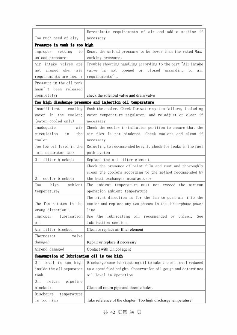
Too much need of air;
Re-estimate requirements of air and add a machine if
necessary
Pressure in tank is too high Improper setting to
unload pressure;
Reset the unload pressure to be lower than the rated Max.
working pressure。 Air intake valves are
not closed when air
requirements are low. ;
Trouble shooting handling according to the part "Air intake
valve is not opened or closed according to air
requirements" 。 Pressure in the oil tank
hasn’t been released
completely; check the solenoid valve and drain valve
Too high discharge pressure and injection oil temperature Insufficient cooling
water in the cooler;
(water-cooled only)
Wash the cooler. Check for water system failure, including
water temperature regulator, and re-adjust or clean if
necessary Inadequate air
circulation in the
cooler
Check the cooler installation position to ensure that the
air flow is not hindered. Check coolers and clean if
necessary Too low oil level in the
oil separator tank
Refueling to recommended height, check for leaks in the fuel
path system
Oil filter blocked; Replace the oil filter element
Oil cooler blocked;
Check the presence of paint film and rust and thoroughly
clean the coolers according to the method recommended by
the heat exchanger manufacturer Too high ambient
temperature;
The ambient temperature must not exceed the maximum
operation ambient temperature
The fan rotates in the
wrong direction ;
The right direction is for the fan to push air into the
cooler and replace any two phases in the three-phase power
line Improper lubrication
oil
Use the lubricating oil recommended by Unicol. See
lubrication section.
Air filter blocked Clean or replace air filter element Thermostat valve
damaged Repair or replace if necessary
Airend damaged Contact with Unicol agent
Consumption of lubrication oil is too high Oil level is too high
inside the oil separator
tank;
Discharge some lubricating oil to make the oil level reduced
to a specified height. Observation oil gauge and determines
oil level in operation Oil return pipeline
blocked; Clean oil return pipe and throttle holes。 Discharge temperature
is too high Take reference of the chapter” Too high discharge temperature”
共 42 页第 40 页
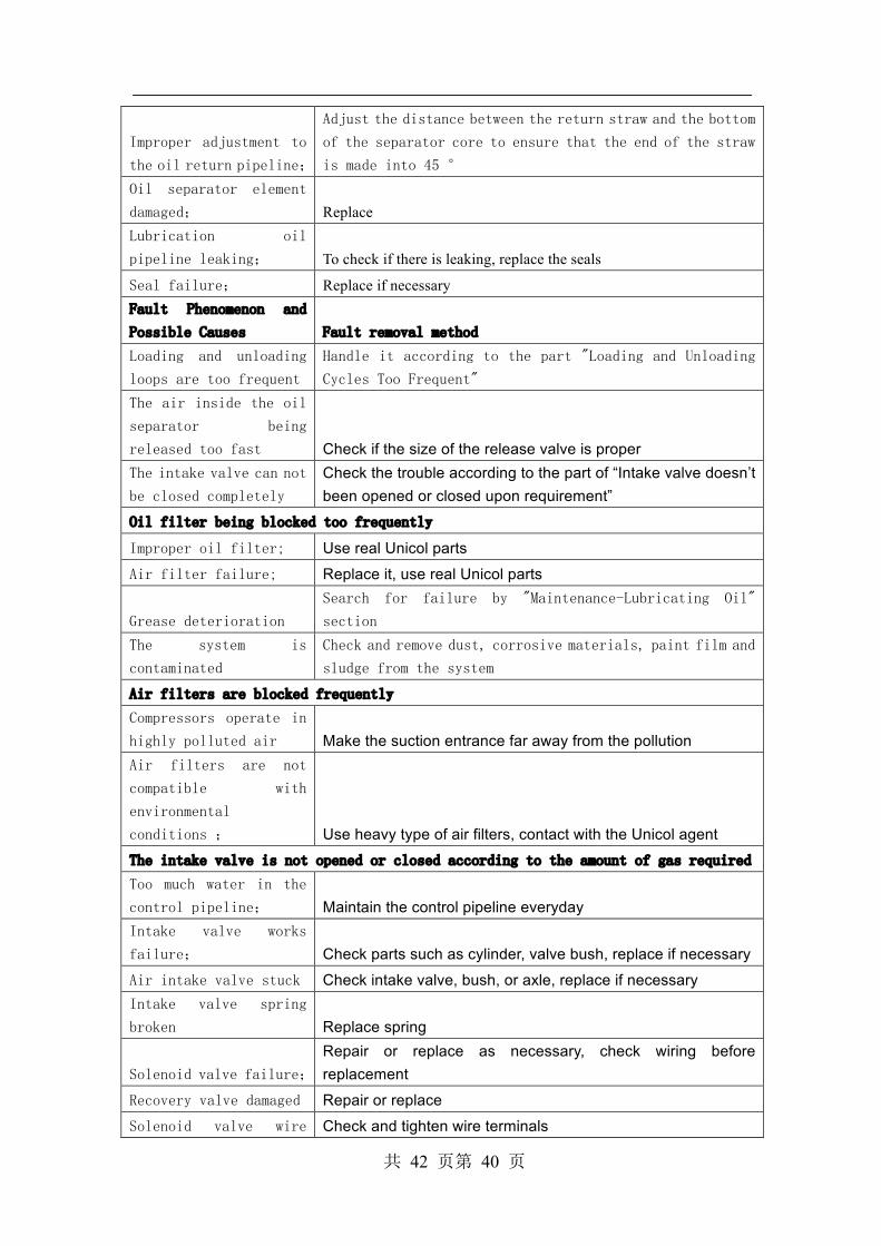
Improper adjustment to
the oil return pipeline;
Adjust the distance between the return straw and the bottom
of the separator core to ensure that the end of the straw
is made into 45 ° Oil separator element
damaged; Replace Lubrication oil
pipeline leaking; To check if there is leaking, replace the seals
Seal failure; Replace if necessary Fault Phenomenon and
Possible Causes Fault removal method
Loading and unloading
loops are too frequent
Handle it according to the part "Loading and Unloading
Cycles Too Frequent" The air inside the oil
separator being
released too fast Check if the size of the release valve is proper The intake valve can not
be closed completely
Check the trouble according to the part of “Intake valve doesn’t been opened or closed upon requirement”
Oil filter being blocked too frequently
Improper oil filter; Use real Unicol parts Air filter failure; Replace it, use real Unicol parts
Grease deterioration
Search for failure by "Maintenance-Lubricating Oil"
section The system is
contaminated
Check and remove dust, corrosive materials, paint film and
sludge from the system Air filters are blocked frequently Compressors operate in
highly polluted air Make the suction entrance far away from the pollution Air filters are not
compatible with
environmental
conditions ; Use heavy type of air filters, contact with the Unicol agent The intake valve is not opened or closed according to the amount of gas required
Too much water in the
control pipeline; Maintain the control pipeline everyday Intake valve works
failure; Check parts such as cylinder, valve bush, replace if necessary Air intake valve stuck Check intake valve, bush, or axle, replace if necessary Intake valve spring
broken Replace spring
Solenoid valve failure;
Repair or replace as necessary, check wiring before replacement
Recovery valve damaged Repair or replace Solenoid valve wire Check and tighten wire terminals

共 42 页第 41 页
connector loose
Compressors can not be unloaded when compressed air requirements are reduced
Improper set of unload
pressure; Reset the unload pressure Control pipeline leaks; Check and maintain the connectors in control pipeline Compressed air pipeline
leaks ; Check all compressed air pipeline Release valve damaged Replace or repair if necessary
Solenoid valve damaged; Repair or replace Regulator valve damaged; Repair or replace。
The compressor fails to load when the pressure reduces to the lower control limit Wire connection lines
loose; Check all connection lines。 The intake valve is
stuck Check and repair。 Regulator valve
failure; Clean the throttle holes or replace the valve Improper set of load
pressure; Reset。 Solenoid valve damaged; Repair or replace Transforming between loading and unloading is too fast Fault Phenomenon and
Possible Causes Fault removal method
Working pipe volume is
too small ; Increase the tank volume Unload pressure setting
close to regulator valve
setting ;
Reset pressure the difference between the unloading
pressure and the regulator valve Control pipelines leak; Check and repair Waterlogging or
freezing in control line Empty control line, repair filter, check valve throttle. Excessive water content of compressed air at exhaust end
Oil separator block; Clean or replace Installation or
operation problem; Check other compressors in the system Water-cooler
leaks(water-cooled type
only) Replace the water-cooler Safety valve opens abnormally Improper set of
unloading pressure
Readjust the unloading pressure to obtain the correct pressure difference range
The intake valve did not Solved by "valve not opened or closed as required" section 。

共 42 页第 42 页
close as required
Separator blocks Replace element oil separator
Defective safety valve ;
Check that the safety valve is in the correct pressure setting position. Replace if leakage 。
Top Related