


Languages
Pages
Legal


(88i~)
A
MINISTRY OF SUPPLY
AERONAUT][CAL RESEARCH COUNCZL REPORTS AND -MEMORANDA
t~,l,~,,-. ~ o ~ ~:= %-. :,&,~
Method of ~esting Smooth ~Sngs for Znkia~Shspe and Resistance to
]Distortion under Load '
B y '
J. C. KINO~ B.Sc.(ENG,) A N D D . H . TROLLOPE~ B . S c o
Crowz Copyright Reserved
LONDON: HIS MAJESTY'S STATIONERY OFFICE
~951 FOUR. SI-IILLINOS NET
...... ~.-.%
] ~ 91,,I~
h ., v '~ ! / .........

A Method Shape and
B y
j . c . KINO, B.Sc.(ENo.) AND D. H. TROLI~OVE, B.SC.
of Testing Resistance
Smooth Wings for Initial to Distortion under Load
COMMUNICATED BY THE PRINCIPAL DIRECTOR OF SCIENTIFIC RES'EARCH (AIR),
MINISTRY OF SUPPLY , '~-"~' ~,~.~_~:~-~,....-'~& r , ,~h l~ . l f e~ . -~' ~
g,:> ......... . /
I.,~.-~-'~- and Memoranda
May, 1945
Summary.--The development of special smooth wing constructions for laminar-flow aerofoils calls for a simple testing technique to check the suitability of these new designs. In the method now used a short parallel length of wing bounded by ribs is tested under uniform bending with torsion and internal pressure superimposed when necessary. A standard specimen and standard testing technique are described. A review of the existing instruments for measuring surface irregularities is included.
1. Introduction.--The satisfactory development of laminar-flow aerofoil sections, having lower drag coefficients than previous sections, has led to the problems of designing and con- structing wings fulfilling the requirements for surface smoothness both initially and under load. Theoretical design data for smooth wings having the conventional spar and reinforced light alloy sheet construction has already been published 1 and such wings are under development. To • check the suitability of such wings and others of less conventional construction tests are being made on samples o f these wings.
The purpose of the tests is to examine the initial shape of the specimens, to see whether they remain sufficiently smooth under light manoeuvring loads and to decide whether proof loading produces enough permanent deformation to destroy their laminar flow properties. The object of this report is to facilitate co-operation between the Royal Aircraft Establishment and firms interested in the smooth wing tests and to encourage uniformity in the test methods. To make the report complete information is included on the measurement of surface waviness.
Before going further it is necessary to summarize the present position regarding the require- ments for smooth wings. Until a great deal more work has been done and the difficulties inherent in smooth wing production have been at least partially solved, no official requirements can be laid down. In the next section, however, an at tempt has been made to formulate such require- ments as a basis for experiment and discussion,
2. Requirements for Smooth Wings.--2.1. Limiting Dimensions for Surface Distortion.--Surface irregularities on the wing surface forward of the design position of the transition point may cause turbulent flow and a resulting increase in the drag coefficient. The three major forms which these irregularities take together with approximate values for their maximum permissible size if transition is to be avoided are listed below : - -
(a) Buckles and Ridges.--The ratio of amplitude to wave length should not exceed 1 in 1,000 when measured in a chordwise direction and 3 in 1,000 when measured in a spanwise direction.
*R.A.E. Report S.M.E. 3327--received 10th July, 1945.
1 ~ba2s4) " a

(b) Ste2bs at Skin Joints.--The difference in level of the sheets at skin joints should not exceed 0.0005 in. ; this applies especially to spanwise jo in ts .
(e) Rivet and Screw Heads.--The protrusion or depression of these connections relative to the skin level should not exceed 0.0005 in., whilst the sharp corner Often found at the edge of spot welds should not exceed 0. 0002 in.
2.2. Smoothness u~der Load.--The operational conditions under which this smoothness must be maintained may be summarized in the following three requirements :=-
(a) The wing must be smooth initially. (b) The wing should remain smooth under light manoeuvring or gust loads up to a factor
of ~ = l~g at maximum level speed or ec0nomical cruising speed, depending on the operational use of the aircraft.
(c) Proof loading of the wing should not permanently distort the wing surface beyond the limiting amounts described" above.
3. Choice of Specime~.--Suitable specimens for these investigations should be (a) Suitable for wind tunnel, distortion and strength tests. (b) As simple as possible. (c) Similar to each other to facilitate comparison of results.
I t is therefore desirable that if possible a standard specimen be provided m a d e to the dimensions recommended below.
3.1. A erofoil Sectio~.--When it is required merely to obtain design information on a specific type of smoo.th wing construction it is recommended that an aerofoil section belonging either to the NACA 65 or 66 series with a tic ratio of 15 or 18 per cent. be used. However, if information is re.quired on a design of smooth wing intended for a particular aircraft, it is preferable that the specimen should have the actual aerofoil section to be used.
3.2. Pla~ Shape of SDecimen.--~aving in mind the need for a simple test rig, the choice of shape lies between a parallel specirhen tested under uniform bending and a tapered specimen tested as a cantilever with a single up-load at the end of an outrigger. These two types of test are illustrated in Fig. 1. The parallel specimen represents in all cases a narrow chordwise element of wing (whether the wing is tapered or not), over which there is no appreciable change of betiding moment or shear force. When tested under uniform bending it becomes an improved type of panel-test in which suction loads and rib anchorages can be represented. For test purposes, this type of specimen has numerous technical advantages over al tapered specimen. On the other hand it has been argued that as part of the object of making these specimens is to t ry out manu- facturing processes for smooth wings, which are obviously more complex with tapered wings, any specimen used for test should be tapered. This point is appreciated, but it has to be balanced against the undesirable consequence that a special test rig has to be built for each specimen.
I t is therefore recommended that a parallel specimen be used and, to suit the appropriate National Physical Laboratory Wind Tunnel, it should have a 6-ft. chord and a length of 8 ft. to 10 ft. Such a specimen may be considered as representing part of a medium aircraft wing near the tip or as a scale model of a section of a large aircraft wing. I t may be desirable in certain cases, such as very large aircraft, to make a larger specimen for distortioli and strength tests as a check on manufacturing methods. '
This report is concerned mainly with the 6-ft. chord parallel-slice type of specimen tested under un i form bending moment.
: 4. Preparation of Specime~.--For the structural distortion tests, the specimen with all necessary end fittings has to be prepared in such a manner as to ensure correct distribution Of the applied loads. The majori ty of additional fittings can only be assembled to the specimen after completion of the aerodynamic tests at the N.P.L.
4.1. Pressure Co~mctio~s.--The aerodynamic suction experienced by a wing in flight is simulated in these tests by internal pressure. This necessitates complete sealing of the specimen
2 , "

to prevent air leakage during test. This sealing is achieved by filling all rivet and screw holes, skin joints and similar discontinuities with some suitable filling during construction. To make the ends of the specimen airtight thin rubber sealing strips should be provided between the end sections and the end bulkheads (see section 4.2 below). Where cellular or corrugated construction is used suitably disposed holes must be drilled to ensure the pressure is effective over the skin itself. The necessary pressure connections should include one inlet and two outlets for measuring purposes.
4.2. Bending Fittings.--To distribute the bending moment applied to the specimen suitable fittings and reinforcement must be provided at both ends of the specimen. As it is essential tha t during the application of load the end planes of the specimen remain plane, a stiff bulkhead should b e provided at each end, and the ends should be reinforced adjacent to the bulkheads by doubler plates at least as thick as the underlying skin. Figs. 2 to 4 stlow various types of end fittings designed for use with different smooth wing constructions.
4.3. Torsion Fittir~gs.--For the application of torsion four extra brackets are required fitted to extensions at the fore-and-aft end of each bulkhead, to incorporate horizontal chordwise pins. Examples of these brackets and lugs are shown in Figs. 2 to 4.
5. ~ Method of Test.--5.1. Pressure Loads.--The most convenient method for applying the internal pressure, used to simulate the aerodynamic suction, is by using the compressed air supply usually available in a laboratory but reduced in pressure by a large drum with a hand controlled leak valve. If a pump is used the delivery must be large, as a considerable volume is needed owing to tile presence of many small leaks and to minor failures during tests. The applied pressure should be measured by two mercury U-tube manometers, the second manometer being a check gauge to assist the operator should the other fail at a critical moment.
5.2. Bending Loads.--The method of applying the bending load to a parallel slice type of specimen is illustrated in Fig. 5, which should be studied in conjunction with the photograph of Fig. 6. Vertical stanchions--three or four at either end tlave been found a suitable number - - should be bolted to the end bulkheads at the bottom and connected by a cross beam or beams at the top. The horizontal load is applied either directly by a turnbuckle or by a nutcracker device, illustrated in the figure, the open ends being pulled together by a spider* and the resulting load measured by a spring balance. The ideal chordwise position of the loading point is tha t which results in tile end planes remaining plane. This can be assured by using stiff end bulkheads and by some preliminary tests, using an arrangement of dial gauges similar to that shown in Fig. 7 to determine the best position of loading point.
If the specimen is of the heavy spar type, it may be desirable to apply the load more directly to tile spars by bolting vertical beams to the spar extensions and retaining tile end bulkheads for distributing some of the load into the interspar skin.
5.3. Torsion Loads.--These are applied by up-and-down loads at either end of one of the bulkheads, the other bulkhead being pin-jointed to tile supporting framework to provide the necessary vertical reactions while allowing the end plane to rotate about this joint to t ake 'up distortions arising from the applied bending load. A method of applying the up-and-down torsion loads is illustrated in Figs. 5 and 6.
5.4. Sim#lificatio~ of Rig.--If sufficient information can be obtained by the application of bending and pressure only, it is not necessary to provide the supporting framework otherwise necessitated by tile torsion loading gear. The specimen could then be supported on rollers, .the application of bendingand pressure loads being through a self-contained rig. This is especially useful with large specimens, when the provision of suitable supporting and torsion rigs is a major problem.
*Spider : this is the term Used for a straining gear comprising a long screwed bar fitted with a nut, having caps tan arms for ease of rotation, bearing against a collar or t runnion block.
3

6. Test Programme and Loading Conditions.--The following series of tests is made on each specimen after completion of the wind tunnel tests.
(1) Measurements of initial shape.
(2) Elastic distortion tests.
(3) Proof or permanent distortion tests.
(4) Ult imate test. As it is not possible to represent correct conditions of end stress and pressure on upper and lower
surfaces at the same time it is usual to make the top surface conditions fully representative, and to make all measurements, except the initial shape measurements, on this surface, as this is usually the most critically loaded surface from a skin distortion aspect.
• The test programme listed above is described in the following sections. The test measurements required are also described, but details of suitable measuring instruments are left to section 7.
6.1. Measurements of Initial Shape.--Information is first required on whether the type of construction and method of manufacture are suitable for the production of smooth wings. These measurements should be made on both surfaces forward of the transition point and should include measurements of the surface waviness, rivet, screw or spot weld protrusions and steps at skin joints, using the appropriate instruments.
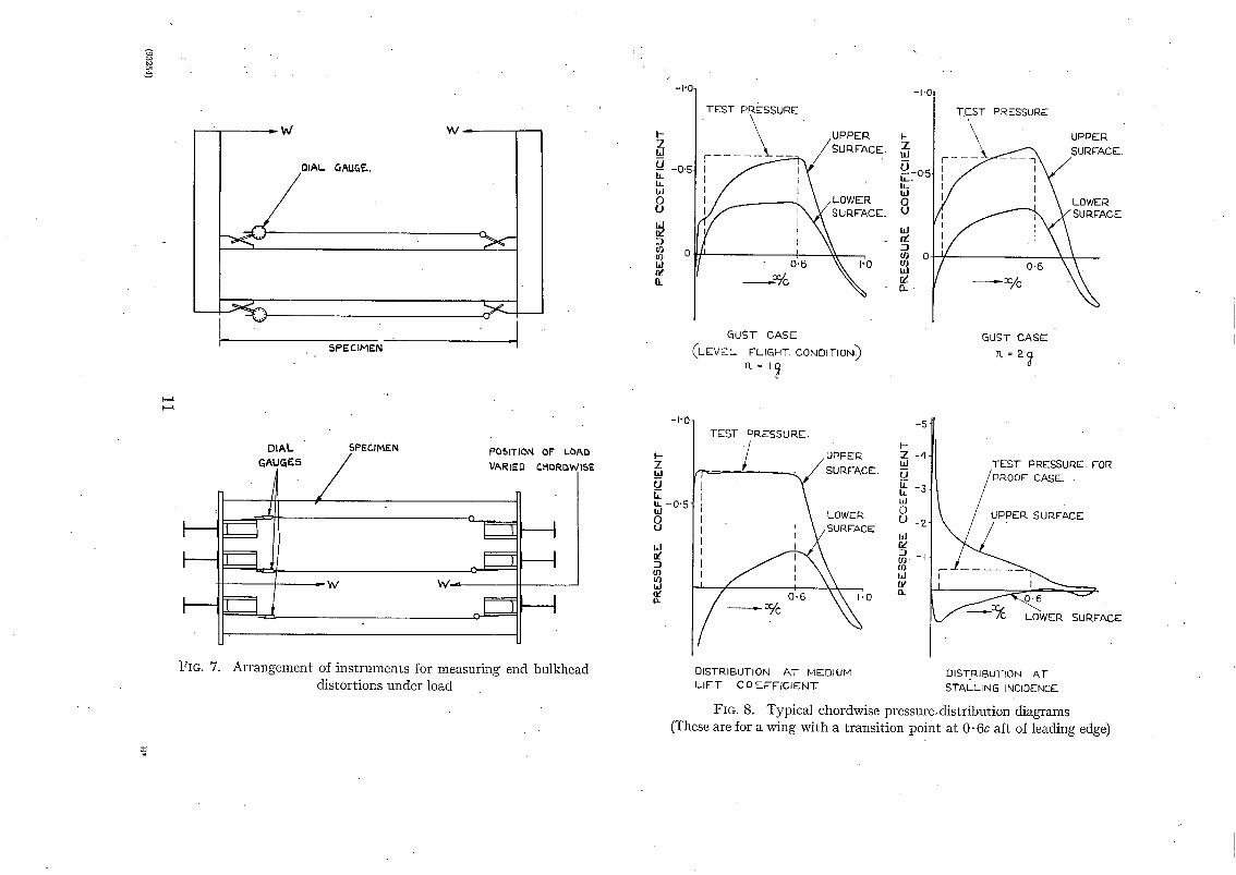
6.2. Elastic Distortion Tests up to a Factor n = l~g.--These tests are made to ensure that the wing surface remains smooth under light manoeuvring or gust loads at either the maximum level speed or the_ cruising speed, according to the aircraft type. The test loads should be calculated on these assumptions and the applied internal pressure should correspond to the peak suction on the top surface at the appropriate speed (Fig. 8). I t will be found that the pressure varies very slightly above lg loading owing to the large initial suction at zero lift. This is illustrated by the graphs of Fig. 9. The gust case loading is best illustrated by line C in Fig. 10, a rationalized stressing diagram for a typical aircraft.
To provide sufficient information it is recommended that tests be made up to ! ~g under
(a) Pressure only.
(b) Pressure and bending.
(c) Pressure and torsion.
(d) Pressure, torsion and bending.
Measurements of surface distortion should be made.
6.3. Proof Load Tests.--Tests are next required to determine the load which produces enough permanent distortion to destroy the aerodynamic efficiency of the wing. The test case should be chosen to give the most severe permanent buckling of the skin. As the pressure has a stabilising effect on the skin the tests would normally be made under the centre of pressure forward condition. This gives the lowest pressures over the part of the wing aft of the 5 to 10 per cent. chord position, as illustrated by the pressure variation graph of Fig. 10, and would therefore ensure that over the least curved part of the surface the pressure would be a minimum and tha t in the majori ty of wings appreciable torsion would be present. The uniform pressure used should correspond to the minimum over the test part of the chord as illustrated in Fig. 8.
A series of tests under the chosen loading conditions should be made, each test being taken a unit factor higher than the previous test until at zero load there is a permanent set in the skin in excess of that permitted. Measurements of the vertical deflection of the spars should be made in these tests as well as measuremerfts of skin distortion.
4

6.4. 'Ultimate Test.--The choice of loading case for this test depends largely on the design information required by the firm. It is usual during this test to omit the internal pressure as a safety precaution, and only the vertical deflections of the spars are measured.
6.5. Adjustment of A1bl~lied Bending and Torsion Loads:--The method of test described in section-4 produces a direct compression load as well as a bending moment, and hence the compression in the top surface is greater than the tension in the bottom surface. The magnitude of tile load at the top of the vertical arms should therefore be adjusted accordingly.
In the case of specimens of box construction the method of test does not reproduce the shear stress distribution arising from the vertical shear loads. Omission of this vertical shear results in a lower shear stress in the skin near the webs. Consequently the applied torsion load should be increased above the calculated value to m a k e u p for this omission approximately.
7. Measuring Instruments used in Smooth Wing Tests.--7.1. General Remarks.--The measure- ment of surface waviness and other irregularities in the skin of smooth wings may not be restricted to one instrument. A brief description of the various instruments, their application, and notes on possible future developments of particular types, are given at the end of this section.
The number of wing sections at which measurements should be made depends on the type of instrument and the surface finish. Enough initial shape measurements should be made to enable a good average picture of tile state of the surface to be obtained. In the distortion and proof tests the measurements should be made on at least the three sections comprising a central rib and half a rib pitch to either side.
7.2. Notes on Measuring Instruments.--(a) The Profile Gauge.--This gauge is intended for comparing the overall shape of the specimen aerofoil section with the true section as given by the aerofoil ordinates. I t is unsuitable for detecting spanwise ridges of very small amplitude and wave length owing to the difficulties of manufacture to very fine limits.
The features of the gauge are illustrated in Figs. 11 and 12. I t is used in conjunction with wedge or feeler gauges for measuring tile gap between the wing and tile gauge edge. (The gauge illus- trated in Fig. 11 was designed for use on a wing from which tile trailing edge had been detached.)
(b) The Traverse Gauge.--A photograph of this gauge is shown in Fig. 11, which illustrates its general design features. Its use is almost entirely limited to spanwise measurements, as chord- wise traverses are almost impossible to interpret, owing to the rapid variation of the gauge reading due to the surface curvature masking any slight waviness present. I t is, however, useful for measuring the step at spanwise skin joints, as illustrated by Fig. 12b.
(c) The Curvature Gauge.--A gauge of this type is illustrated in Fig. 11 in sufficient detail to show its main features. The present recommendations regarding the application of this gauge to smooth wing measurements may be summarized as follows. The feet should be set 2 in. apart and tile dial gauge midway between them. The gauge so adjusted should then be traversed chordwise across the wing at a humber of sections, readings being recorded at suitable intervals. A graph of the results will be of the form shown in Fig. 14 and the wing is smooth enough if the width of the "curvature gauge corrdation band ", enclosing all the results, is not greater than 0. 004 in. This is further illustrated on the graph of Fig. 14. Work is proceeding on tile applica- tion of this instrument and an auto-recording type is also under development.
(d) The Dial Board.--The dial board is of use where the type and extent of buckling can be predicted with a reasonable degree of accuracy. This instrument mounts a number of dials on a rigid board, suitably supported on the wing, locating the dials at the estimated positions of the crests and troughs of any buckling which may occur. A dial board used on some tests on a smooth wing of corrugated construction is shown in Fig. 1.1. The supporting blocks and fittings, which may be positioned at a number of sections along the wings, should provide for positive location of the board in all directions without preventing any distortion of the wing under load.

le) Chequer Board Reflections.--In its present form this method is only suitable for locating small distortions which are not discernible to the unaided eye. Some tests of the method for the quantitative analysis of surface waviness are described in Refs, 3, 4 and 5. Before the method can be applied to the location of buckles, the surface of the specimen has to be polished to some- thing like mirror finish. A chequer board, of one of the types shown in Fig. 13, is held in a span- wise direction in a plane normal to the wing surface and traversed to and fro. The reflection of the board in the wing is observed by ey~ and even slight buckling shows up well. Buckles so found may then be measured by either a traverse gauge or a curvature gauge.
No.
2
3
Author
D. M. A. Leggett . . . . . .
Staffs of S.M.E. and Aero Depts.
REFERENCES
. . o
• °
Title, etc.
Data for the Design of Smooth Wing Surfaces. R . & M. 2193. January, 1944.
The Design of Smooth Wings. A.R.C. 6334. November, 1942.
Preliminary investigation into the Possible Utilization of Reflection Methods for the Measurement of Deformations on Smooth Wing Specimens. Test Note No. S.M.E. 1702.
Measurement of Surface Deformation by Reflection Methods. Note on some Preliminary Photographs of Polished, Flat and Buckled Plates. Test Note S.M.E. 1772.
Measurements of Sulface Deformation by Reflection Methods-- Photographs taken during Test on Armstrong-Whitworth 6-ft. chord Smooth Wing. Test Note S.M.E. 1869.
6

FIG. 2. Construction of end bulkheads.
CAST IRON ~HOE$ 1 ~ E~,[~ ANGLF.
2 CAST iRON .~HOE~,
~ENT I ~ ~ -
IJ ~ f INT~'R~AL P L m ~ -
i ( ~ - , / " ~ ' ~ " ~ ' ~
t I ' ~ PART SECTION A-A
A .; .
. . I I I~11 , I ! I
Method 1 : separate castings bolted to angle or channel stiffeners
g
9-
\ \ \ \ \ \
i
l-
w
P
.5
/~ Z W z k / h i & ffl
t ' l Id iv
I
)
r
i.i
t~
h 0 p-
<~ 4 ¸
I -
>- , ¢ t -
~ Q
(D
" 3 -
" B
uO - ~ b/)
I v

, - ~ _ _ . i:)ISTKI~UTING 'SHOES" " ' ~ 1 I " ~ i ~ / I INTEGRP, L WITH CP~STING
• ]1 hOLlO C~$T~NG5 gOL'i'Eg I i I I '1 I l ' I I ',' Y TOGETHER AT ENOS
I I • . .
RUBBEr sEALInG I I ' I t I " I A ~1 '/ I I STP-.IP I ,I I ' , l I II I I I~ I I /
I 'l
; I /
i ~ - - - I I I ! ; I - - T ~ = ~ T - - . . ~ ' , ~ / i I I I ' I ' l, , I '1 I
LL. / - r ' -~ ' -~q :2 : ! : 1 1 ; ' '~ i : i i I i /AY J ~ /1 r r , ~ ' , : I , ! ~ ~ . ~ / /
TO~ION Acr ~'ACHED
TO HORIZONTAL PIN,
A F I G . 3.
.,ENn pLATE..
~TE. gR ~CKET.
P A R T 5 E C q ' I O N P.,IA.
Construction.of end bulkheads. Method 2 : Distributing " shoes " incorporated in castings acting " as bulkhead stiffeners
VER:TICAL 6ENDING P-~'AM5. T ~1 "-Jr1"-- ~ II T~'(,IN REINFORCEMENT. ', t'
ii d H !', '1', ',
~ F ,, 1,1 II " II It II
{- ' ' n Li i l l ii
0 LINE .
~ ~ ii il I 1 ~ ~ L j I I I I
LINK5 FOR APPLYING "ToR5ION A'TTACHEO HERE..
FIG. 4.
RUBB,ER SEALING hTRSR
A'T-rNcH MEN'r BR~.CI<.ETS ON 5PAR. ~OOMS
P A E T ,hEC' f lON A - A .
Method of applying bending load to specimen of heavy spar type

%
r.D
FULCRUM POINTS FOP. LEVERS FOR APPLICATION OF //TORSION LOADS. (THESE POINTS ARE LOCATED ON / /
BENDING BEAMS / / A N D SUPP01RTED BY TEST FRAME."I
I L - J " ~ J ', SPECIMEN / HANGING WEIGHER
/ • S TURNBUCKLE /
m
HORIZONTAL PIVOTS AT FORE AND AFT END 0F THIS BULKHEAD
SPlOF"R STRAININ G GEAR
I~NUTCRACKER" BEAMS FOR THE APPLICATION OF" THE BENDIN~i LOAD.
HORIZONTAL LOAD
S-TON SPRING BALANCE NOTE- THIS DIAGRAM SHOULD BE READ IN
~ l CON3"UNCTION WITH THE PHOTOGRAPH OF FIG 6 WHICH SHOWS A SPECIMEN FITTED IN A ~IG OF THIS TYPE
- FOR TORSION LEVERS
Ym. 5. Diagram showing suggested loading rig for testing smooth wing specimens

I .
! I
/ f i - - f .
FIG. 6. Front view of specimen in test frame
10
L
- ~ - - . - - - - ~ - W
OI/M,. QAU¢.I,~.
SPECIMEN
DIAL SPECIMEN GAUGF-.,5 /
d " /
POSITION OF LO&D VARIED c ltORBWISE
q
LI1
o
m
FIG. 7. Arrangement of il~s~ruments for measuring end bulkhead distortions under load
I- Z IlJ
IL LL ILl 0 O kl Iz' :3
M 0-
-I'0
-O'S
0
TEST PRESSURE \ \ UPPER
_ ~ S U ~ F A C E .
/ ~ - k \ / L ° W E R %URFACE. I " "a"l 0[6 \ L PIO
GuST CASE (LEVEl.- FLIGHT. CON01TION~
1l= I'~
-I'0
TEST PRESSURE
P ~ UPPER Z F - -- -~- SURFACE.
u ~ - o ' 5 , i
, , 1 ul LOWER
ffl ILl -
GUST CASE 'n. = 2~,
I-- Z w
L
W O U
W
--1 cll ul
n
- I ' 0 -
- 0 " 5
TEST PP-.ESSU RE.
. UPPEI~ i /
- - / SUP, FACE.
I ' I '~ I I ] I LOWER I /SURFACE
01STRIBUTION AT MEDIUM LIFT COEFFICIENT
I--
E Ld 0 El td
L0 W I:1_
-5
-4 TEST PRESSURE. FOR -3 / P R O O F CAsE..
/ RrACE
-Z- i - - I
I
d-- '- '-J
L0*ER
DIST.RIBUTION AT STALLING INCIDENCE-..
FIG. 8. Typical chordwise pressure,disEibution diagrams (These are for a wing with a transition point at 0" 6c aft of leading edge)

u
I - Z
IL t l .
8 t J
Ld
-7 ~3 U'J IJd
IL
3
:E
g . (
l - Z u
Ill O U
I -
- I
I'O
0'8
0.0 /
~ 4
.0
I
I I
. I
J / / I i I
'~ t I
/ I I /
I / i
l / i t
/ I
I [
I i I
i
COMA){ FOI~ UPPER .SURFACE / LEA, DIN~ EDr~E
/ - LIFT COEFFICI
\
/ /
I I I I I
I F /
,/
// ,/
+ .DU~TO qUST
FOR TRN'~ POINT UPPER ,SURFACE
~;i APPI~:)X C-H.~N~IE IN CL ~AR.ISlNP< F~C~VI EFFECT~ FIE:)MOF ~USTI TO Ip4.AT Y MAX~ TO IN( EASE
I ~ " ~ ,Cp MlkX FQI~ TRAN~rI'ION POINT
ON cOWEi~ 51,~FACE I a(o 8o I PJ 10 ° ~0 °
ANC-iI.E OF INCIDENCE = oC FIG. 9. Typical lift and pressure coefficient curves for laminar flow aerofoil, illustrating effect of gust of sufficient magnitude to increase factor from 1 to 1 }
O t a r o
[1-1, ~ o
8
6
C I
)
TYPICAL CLII~VE OF MII~MUM PRESSURE ON TE6T PAinT OF UPPER 5Ui~FACE AT Pi~OOF FAr.TO~. "-V
/
/ /
- - ~ . - 5PEEE) - V
/ -
LINE C - @LJBT
j / cAs~.
,,
/ I I i
I I I i
I- f c~E A
1 i
UNEVEN 6C/kLE )
RATIONALISED ,,~TR E~61NI~ OIAr~ FOR AIR C, R/kFT.
ULTIMATE FACTOR
._PI~O; ~A(
/ I i i
---DYNAMIC PRESSURE -- ]?./o V ~"
I i --,--3PEE0 - V V MAX LEVE.E
(UNEVEN F,C. ~LE) I I
FIG. 10. "Loading conditions--minimum pressure curves and rationa]ised loading diagram.

e * 7 1 " e, 5 ¢ , ' o ' , ' " ~ 1 3 " ~ I s ~
FIG. 11. Smooth wing measuring instruments
K.
TRAVERSE
S ~ 5K IN ~'OINT
~,a~GB
4
I
(3 < Id
Z - i
o I
o.<~" o.bz" o.b~" OI S"TANC ~" INCHr..~
(o..)METHOD OF MEASURING STEP IN SKIN JOINT.
®
I" = "1
a
~'uTu,,,'lw^v~i.~N~'r, = orb - orA+~C
OC
$ja. IF" :Y • 3" THEN £B - t-J-'A.'i"ol"c '~(I-OO3 'i Z
(b)METHOD OF MEASURING SURFACE WAVING USING DIAL GAUGES AT
FIXED LOCATIONS. FIG. ]2
1 3

I
w
ID
,¢
iv :} ~J
0.0~-0
O' 03G
0"0~0
0"0t0
NOTA'T I ON.
PLG'T OF" C U R V A T U R E . G,&LIGE R E S U L T S .
L I N E 5 r ' ,EFINING ROUNDARIE,$ O F " C.-LIRV,'~,'TI3RI
GALIG ~" C O R R E L A T I O N &,~,N o "
q 'HE WIE iTH O F "THIS & A N B S H O U L n No - r
E ~ G E ~ ' [ 5 0 . 0 0 4 " W H E N T H E G A U G E F E F _ T
,~RF_. S E T A'T ~-" A P ~ R ' T .
I I \
\
CORRELATION I~AN 13"
> - - - - _ _
"~ ~ ' / / / W I O T H OF" " CURV,~3"URF- C~'/kUGE
i
IO 2 0 3 0 '~-0
@IST~NC~ AFT Off LEANING E~G~. - ~/o CHOlera
EIG. 14. Diagram ~]lus~rat~ng " curv&ture gauge correlation band "
o ~
e_ e- 4:
c O
21::
(93254) W t . 13/806 K . 5 6/51 ~[w.
Z
Z n e
0
ILl n~ ..j LI.I
1 0 1 - 0
, , inc"
' - ,9 W
0
14
t
o l d ,,i , , ,g~
aP--~ , - - a ~
::3 ~ . ~ :r__ ::3 t~l IL 1
'..~o
::~-o ,I~l t.~.l i - ~___. '3c ~1=
eQ ~ n - o ~ i - _l I~ ~:
• j B Q -
w o p~ - ~- gW
~. o O "
-
131.. >- I--
, , ,
n,- W D
8 "1- (O

(8816) A . E . & ~eehnieN ~e~or~
Publ.Scadons of the Aeronautical[ Research torero{tree
T E C H N I C A L REPORTS OF T H E AERONAUTICAL RESEARCH C O M M I T T E E -
1934-35 Vol. I. Aerodynamics. 4os. (4os. 8d.) Vol. II. 8eaplanes, Structures, Engines, Materials, etc. 4os.. (4os. 8d.)
I935-36 Vol. I. Aerodynamics. 3os. (3os. 7d.) Vol. II. Structures, FMtter, Engines, Seaplanes, etc. 3os. (3os. 7d.)
1936 Vol. I. Aerodynamics General, Performance, Airscrews, Flutter and Spinning. 4os. (4os. 9d.)
Vol. n . Stability and Control, Structures, Seaplanes, Engines, etc. 5os. (5os. Iod.)
1937 Vol. I. Aerodynamics General, Performance, Airscrews, Flutter and Spinning. 4os. (4os. 9d.)
Vol. II. Stability" and Control, Structures, Seaplanes, Engines, etc. 6os. (6IS.)
1938 Vol. I. Aerodynamics General, Performance, Airserews. 50 s. (5IS.) Vol. II. Stability and Control, Flutter, Structures, Seaplanes, Wind Tunnels,
Materials. 3os. (3ox. 9d.)
1939 Vol. I. Aerodynamics General, Performance, Airserews, Engines. 5os. (5os. IId.) Vol. II. Stability and Control, Flutter and Vibnition, Instruments, Structures,
Seaplanes, etc. 63s. (64s. 2d.)
194o Aero and Hydrodynamics, Aerofoils, Airscrews, Engines, Flutter, Icing, Stability and Control, Structures, and a miscellaneous section. 5os. (5 is.)
Certain otker reports proper to the i94 o volume wi l l subsefuently be included in a separate volume.
ANNUAL REPORTS OF T H E AERONAUTICAL RESEARCH C O M M I T T E E - - 1933-34 IS. 6d. (IS. 8d.) 1934-35 IS. 6d. (IS. 8d.)
April I, 1935 to December 31, 1936. 4 s. (4 s. 4d.) 1937 : . :2s. (2s. 2d.) 1938 : IS. 6,/. (IS. 8d.)
1939-48 3 s. (3s. 2d.)
INDEX T O ALL REPORTS A N D MEMORANDA PUBLISHED IN T H E ANNUAL T E C H N I C A L REPORTS, AND SEPARATELY--
April, 195o R. & M. No. 2600. 2s. 6d. (2s. 7d.)
INDEXES T O T H E T E C H N I C A L REPORTS OF T H E ADVISORY C O M M I T T E E ON A E R O N A U T I C S - -
December I, 1 9 3 6 - - J u n e 30, 1939. JuIy r, I 9 3 9 - - J u n e 3 ° , 1945 . July I, 1945 - - J u n e 3 o, 1946. July I, I 9 4 6 - - D e c e m b e r 31, 1946. January I, 1947 - - J u n e 3 o, 1947.
R. & M. No. 1850. R. & M. No. 195o. R. & M. No. 2050. R. & M. No. 215o. R. & M. No. 2250.
IS. 3 d. (IS. 5d.) IS. (rs. 2d.) is. (is. Id.) IS. 3 d. (is. 4d.) ' IS. 3d. (IS. 4d.)
Prices in brackets b~clude postage.
Obtainable from
HIS M A J E S T Y ' S S T A T I O N E R Y O F F I C E York House, Kingsway, LONDON, W.C.2 429 Oxibrd Street, LONDON, W.I )
P.O. Box 569, LONDON, S.E.1 13a Castle Street, EDINBURGH,'2 1 St. Andrew's Crescent, CARDIFF 39 King Street, MANCHESTER, 2 Tower Lane, BlUSTOL, 1
2 Ednmnd Street, BIRMINGHAM, 3 80 Chichester Street, BELFAST
or through any bookseller.
S.O. Code No 23-253i
Top Related