


Languages
Pages
Legal


MetaFabric™ Architecture VirtualizedData Center
Design and Implementation Guide
Release
1.0
Published: 2014-03-18
Copyright © 2014, Juniper Networks, Inc.

Juniper Networks, Inc.1194 North Mathilda AvenueSunnyvale, California 94089USA408-745-2000www.juniper.net
Copyright © 2014, Juniper Networks, Inc. All rights reserved.
Juniper Networks, Junos, Steel-Belted Radius, NetScreen, and ScreenOS are registered trademarks of Juniper Networks, Inc. in the UnitedStates and other countries. The Juniper Networks Logo, the Junos logo, and JunosE are trademarks of Juniper Networks, Inc. All othertrademarks, service marks, registered trademarks, or registered service marks are the property of their respective owners.
Juniper Networks assumes no responsibility for any inaccuracies in this document. Juniper Networks reserves the right to change, modify,transfer, or otherwise revise this publication without notice.
[Insert Series Title] [Insert Book Title]Copyright © 2014, Juniper Networks, Inc.All rights reserved.
The information in this document is current as of the date on the title page.
YEAR 2000 NOTICE
Juniper Networks hardware and software products are Year 2000 compliant. Junos OS has no known time-related limitations through theyear 2038. However, the NTP application is known to have some difficulty in the year 2036.
ENDUSER LICENSE AGREEMENT
The Juniper Networks product that is the subject of this technical documentation consists of (or is intended for use with) Juniper Networkssoftware. Use of such software is subject to the terms and conditions of the End User License Agreement (“EULA”) posted athttp://www.juniper.net/support/eula.html. By downloading, installing or using such software, you agree to the terms and conditions ofthat EULA.
Copyright © 2014, Juniper Networks, Inc.ii

Table of Contents
Part 1 MetaFabric™ArchitectureVirtualized ITDataCenterDesignandImplementation Guide
Chapter 1 Overview . . . . . . . . . . . . . . . . . . . . . . . . . . . . . . . . . . . . . . . . . . . . . . . . . . . . . . . . . . 3
MetaFabric Architecture Overview . . . . . . . . . . . . . . . . . . . . . . . . . . . . . . . . . . . . . . 3
Domain . . . . . . . . . . . . . . . . . . . . . . . . . . . . . . . . . . . . . . . . . . . . . . . . . . . . . . . . . . . . 5
Goals . . . . . . . . . . . . . . . . . . . . . . . . . . . . . . . . . . . . . . . . . . . . . . . . . . . . . . . . . . . . . . 6
Audience . . . . . . . . . . . . . . . . . . . . . . . . . . . . . . . . . . . . . . . . . . . . . . . . . . . . . . . . . . . 7
Validated Solution Design and Implementation Guide Overview . . . . . . . . . . . . . . 8
MetaFabric 1.0 Overview . . . . . . . . . . . . . . . . . . . . . . . . . . . . . . . . . . . . . . . . . . . . . . 8
Solution Overview . . . . . . . . . . . . . . . . . . . . . . . . . . . . . . . . . . . . . . . . . . . . . . . . . . . 10
Compute . . . . . . . . . . . . . . . . . . . . . . . . . . . . . . . . . . . . . . . . . . . . . . . . . . . . . . 10
Network . . . . . . . . . . . . . . . . . . . . . . . . . . . . . . . . . . . . . . . . . . . . . . . . . . . . . . . . 11
Storage . . . . . . . . . . . . . . . . . . . . . . . . . . . . . . . . . . . . . . . . . . . . . . . . . . . . . . . . 12
Applications . . . . . . . . . . . . . . . . . . . . . . . . . . . . . . . . . . . . . . . . . . . . . . . . . . . . 12
High Availability . . . . . . . . . . . . . . . . . . . . . . . . . . . . . . . . . . . . . . . . . . . . . . . . . 13
Class of Service . . . . . . . . . . . . . . . . . . . . . . . . . . . . . . . . . . . . . . . . . . . . . . . . . 13
Security . . . . . . . . . . . . . . . . . . . . . . . . . . . . . . . . . . . . . . . . . . . . . . . . . . . . . . . 13
Network Management . . . . . . . . . . . . . . . . . . . . . . . . . . . . . . . . . . . . . . . . . . . . 14
Chapter 2 Design . . . . . . . . . . . . . . . . . . . . . . . . . . . . . . . . . . . . . . . . . . . . . . . . . . . . . . . . . . . . 17
Design Considerations . . . . . . . . . . . . . . . . . . . . . . . . . . . . . . . . . . . . . . . . . . . . . . . . 17
Design Scope . . . . . . . . . . . . . . . . . . . . . . . . . . . . . . . . . . . . . . . . . . . . . . . . . . . . . . 18
Design Topology Diagram . . . . . . . . . . . . . . . . . . . . . . . . . . . . . . . . . . . . . . . . . . . . . 19
Design Highlights . . . . . . . . . . . . . . . . . . . . . . . . . . . . . . . . . . . . . . . . . . . . . . . . . . . 20
Solution Design . . . . . . . . . . . . . . . . . . . . . . . . . . . . . . . . . . . . . . . . . . . . . . . . . . . . . 21
Compute . . . . . . . . . . . . . . . . . . . . . . . . . . . . . . . . . . . . . . . . . . . . . . . . . . . . . . . 21
Virtual Machines . . . . . . . . . . . . . . . . . . . . . . . . . . . . . . . . . . . . . . . . . . . . . 21
Servers . . . . . . . . . . . . . . . . . . . . . . . . . . . . . . . . . . . . . . . . . . . . . . . . . . . . 22
Hypervisor Switching . . . . . . . . . . . . . . . . . . . . . . . . . . . . . . . . . . . . . . . . . 23
Blade Switching . . . . . . . . . . . . . . . . . . . . . . . . . . . . . . . . . . . . . . . . . . . . . 24
Network . . . . . . . . . . . . . . . . . . . . . . . . . . . . . . . . . . . . . . . . . . . . . . . . . . . . . . . 26
Access and Aggregation . . . . . . . . . . . . . . . . . . . . . . . . . . . . . . . . . . . . . . . 27
Core Switching . . . . . . . . . . . . . . . . . . . . . . . . . . . . . . . . . . . . . . . . . . . . . . 28
Edge Routing and WAN . . . . . . . . . . . . . . . . . . . . . . . . . . . . . . . . . . . . . . . 31
Storage . . . . . . . . . . . . . . . . . . . . . . . . . . . . . . . . . . . . . . . . . . . . . . . . . . . . . . . 35
Applications . . . . . . . . . . . . . . . . . . . . . . . . . . . . . . . . . . . . . . . . . . . . . . . . . . . . 37
Compute Management . . . . . . . . . . . . . . . . . . . . . . . . . . . . . . . . . . . . . . . 38
Network Management . . . . . . . . . . . . . . . . . . . . . . . . . . . . . . . . . . . . . . . . 38
Network Services . . . . . . . . . . . . . . . . . . . . . . . . . . . . . . . . . . . . . . . . . . . . 38
Business-Critical Applications . . . . . . . . . . . . . . . . . . . . . . . . . . . . . . . . . 39
iiiCopyright © 2014, Juniper Networks, Inc.

High Availability . . . . . . . . . . . . . . . . . . . . . . . . . . . . . . . . . . . . . . . . . . . . . . . . 39
Hardware Redundancy . . . . . . . . . . . . . . . . . . . . . . . . . . . . . . . . . . . . . . . 39
Software Redundancy . . . . . . . . . . . . . . . . . . . . . . . . . . . . . . . . . . . . . . . 40
Class of Service . . . . . . . . . . . . . . . . . . . . . . . . . . . . . . . . . . . . . . . . . . . . . . . . . 47
Security . . . . . . . . . . . . . . . . . . . . . . . . . . . . . . . . . . . . . . . . . . . . . . . . . . . . . . . 48
Application Security . . . . . . . . . . . . . . . . . . . . . . . . . . . . . . . . . . . . . . . . . 49
Perimeter Security . . . . . . . . . . . . . . . . . . . . . . . . . . . . . . . . . . . . . . . . . . . 51
Secure Remote Access . . . . . . . . . . . . . . . . . . . . . . . . . . . . . . . . . . . . . . . 52
Network Management . . . . . . . . . . . . . . . . . . . . . . . . . . . . . . . . . . . . . . . . . . . 53
Out-of-Band Management . . . . . . . . . . . . . . . . . . . . . . . . . . . . . . . . . . . . 55
Network Director . . . . . . . . . . . . . . . . . . . . . . . . . . . . . . . . . . . . . . . . . . . . 57
Security Director . . . . . . . . . . . . . . . . . . . . . . . . . . . . . . . . . . . . . . . . . . . . . 57
Performance and Scale . . . . . . . . . . . . . . . . . . . . . . . . . . . . . . . . . . . . . . . . . . . 57
Summary of Key Design Elements . . . . . . . . . . . . . . . . . . . . . . . . . . . . . . . . . . . . . 58
Benefits . . . . . . . . . . . . . . . . . . . . . . . . . . . . . . . . . . . . . . . . . . . . . . . . . . . . . . . . . . 58
Chapter 3 MetaFabric 1.0 High Level Testing and Validation Overview . . . . . . . . . . . . . 61
Overview . . . . . . . . . . . . . . . . . . . . . . . . . . . . . . . . . . . . . . . . . . . . . . . . . . . . . . . . . . 61
Key Characteristics of Implementation . . . . . . . . . . . . . . . . . . . . . . . . . . . . . . . . . . 62
POD1 (QFX3000-M QFabric) Configuration . . . . . . . . . . . . . . . . . . . . . . . . . . 63
POD2 (QFX3000-M QFabric) Configuration . . . . . . . . . . . . . . . . . . . . . . . . . . 63
Core Switch (EX9214) Implementation . . . . . . . . . . . . . . . . . . . . . . . . . . . . . . 64
Edge Firewall (SRX3600) Implementation . . . . . . . . . . . . . . . . . . . . . . . . . . 64
Edge routers (MX240) Implementation . . . . . . . . . . . . . . . . . . . . . . . . . . . . . 64
Compute (IBM Flex chassis) Implementation . . . . . . . . . . . . . . . . . . . . . . . . . 65
OOB-Mgmt (EX4300-VC) Implementation . . . . . . . . . . . . . . . . . . . . . . . . . . 65
Hardware and Software Requirements . . . . . . . . . . . . . . . . . . . . . . . . . . . . . . 66
Chapter 4 Transport (Routing and Switching) Configuration . . . . . . . . . . . . . . . . . . . . . 73
Network Configuration . . . . . . . . . . . . . . . . . . . . . . . . . . . . . . . . . . . . . . . . . . . . . . . 73
Overview . . . . . . . . . . . . . . . . . . . . . . . . . . . . . . . . . . . . . . . . . . . . . . . . . . . . . . 73
Configuring theNetworkBetween theDataCenterEdgeand theDataCenter
Core . . . . . . . . . . . . . . . . . . . . . . . . . . . . . . . . . . . . . . . . . . . . . . . . . . . . . . 73
Topology . . . . . . . . . . . . . . . . . . . . . . . . . . . . . . . . . . . . . . . . . . . . . . . . . . . 74
Verification . . . . . . . . . . . . . . . . . . . . . . . . . . . . . . . . . . . . . . . . . . . . . . . . . . . . . 81
Verification . . . . . . . . . . . . . . . . . . . . . . . . . . . . . . . . . . . . . . . . . . . . . . . . . . . . . . . . 81
Implementing MC-LAG Active/Active with VRRP . . . . . . . . . . . . . . . . . . . . . . . . . . 85
Summary of Implementation Details for MC-LAG Active/Active . . . . . . . . . . 85
MC-LAG Configuration for Better Convergence . . . . . . . . . . . . . . . . . . . . . . . . 86
Configuring the Network Between the Data Center Core and the Data Center
PODs . . . . . . . . . . . . . . . . . . . . . . . . . . . . . . . . . . . . . . . . . . . . . . . . . . . . . . . . . 86
Verification . . . . . . . . . . . . . . . . . . . . . . . . . . . . . . . . . . . . . . . . . . . . . . . . . . . . . . . . 95
Routing Configuration . . . . . . . . . . . . . . . . . . . . . . . . . . . . . . . . . . . . . . . . . . . . . . 104
Overview . . . . . . . . . . . . . . . . . . . . . . . . . . . . . . . . . . . . . . . . . . . . . . . . . . . . . 104
Topology . . . . . . . . . . . . . . . . . . . . . . . . . . . . . . . . . . . . . . . . . . . . . . . . . . . . . 104
Configuring BGP Between the EDGE and Service Provider . . . . . . . . . . . . . . 106
Verification . . . . . . . . . . . . . . . . . . . . . . . . . . . . . . . . . . . . . . . . . . . . . . . . . . . 108
Configuring OSPF in the Data Center . . . . . . . . . . . . . . . . . . . . . . . . . . . . . . . . 111
Verification . . . . . . . . . . . . . . . . . . . . . . . . . . . . . . . . . . . . . . . . . . . . . . . . . . . . 118
Copyright © 2014, Juniper Networks, Inc.iv
MetaFabric™ Architecture Virtualized Data Center
Chapter 5 High Availability . . . . . . . . . . . . . . . . . . . . . . . . . . . . . . . . . . . . . . . . . . . . . . . . . . 123
High Availability Overview . . . . . . . . . . . . . . . . . . . . . . . . . . . . . . . . . . . . . . . . . . . 123
Hardware Redundancy . . . . . . . . . . . . . . . . . . . . . . . . . . . . . . . . . . . . . . . . . . 123
Software Redundancy . . . . . . . . . . . . . . . . . . . . . . . . . . . . . . . . . . . . . . . . . . . 123
QFabric-M Configuration . . . . . . . . . . . . . . . . . . . . . . . . . . . . . . . . . . . . . 123
Configurint the Core and Edge Router . . . . . . . . . . . . . . . . . . . . . . . . . . . 124
Configuring the Perimeter Firewall . . . . . . . . . . . . . . . . . . . . . . . . . . . . . . 125
Verification . . . . . . . . . . . . . . . . . . . . . . . . . . . . . . . . . . . . . . . . . . . . . . . . . . . . 125
Chapter 6 Class-of-Service Configuration . . . . . . . . . . . . . . . . . . . . . . . . . . . . . . . . . . . . . 129
Class-of-Service Overview . . . . . . . . . . . . . . . . . . . . . . . . . . . . . . . . . . . . . . . . . . . 129
Requirements . . . . . . . . . . . . . . . . . . . . . . . . . . . . . . . . . . . . . . . . . . . . . . . . . 129
Configuring Class-of-Service . . . . . . . . . . . . . . . . . . . . . . . . . . . . . . . . . . . . . . . . . 130
Configuring Class-of-Service (POD Level) . . . . . . . . . . . . . . . . . . . . . . . . . . . 130
Configuring Data Center Bridging and Lossless Ethernet . . . . . . . . . . . . . . . . . . . 130
Configuring Class-of-Service (POD Level) . . . . . . . . . . . . . . . . . . . . . . . . . . . 130
Verification . . . . . . . . . . . . . . . . . . . . . . . . . . . . . . . . . . . . . . . . . . . . . . . . . . . . 134
Chapter 7 Security Configuration . . . . . . . . . . . . . . . . . . . . . . . . . . . . . . . . . . . . . . . . . . . . 137
Perimeter Security . . . . . . . . . . . . . . . . . . . . . . . . . . . . . . . . . . . . . . . . . . . . . . . . . . 137
Overview . . . . . . . . . . . . . . . . . . . . . . . . . . . . . . . . . . . . . . . . . . . . . . . . . . . . . . 137
Configuring Chassis Clustering . . . . . . . . . . . . . . . . . . . . . . . . . . . . . . . . 138
Configure Chassis Clustering Data Fabric . . . . . . . . . . . . . . . . . . . . . . . . 138
Configuring Chassis Clustering Groups . . . . . . . . . . . . . . . . . . . . . . . . . . 139
Configuring Chassis Clustering Redundancy Groups . . . . . . . . . . . . . . . 139
Configuring Chassis Clustering Data Interfaces . . . . . . . . . . . . . . . . . . . 140
Configuring Chassis Clustering – Security Zones and Security Policy . . . 141
Verification . . . . . . . . . . . . . . . . . . . . . . . . . . . . . . . . . . . . . . . . . . . . . . . . . . . . 144
Configuring Network Address Translation . . . . . . . . . . . . . . . . . . . . . . . . . . . 144
Configure Source NAT . . . . . . . . . . . . . . . . . . . . . . . . . . . . . . . . . . . . . . . 144
Configure Destination NAT . . . . . . . . . . . . . . . . . . . . . . . . . . . . . . . . . . . . 145
Verification . . . . . . . . . . . . . . . . . . . . . . . . . . . . . . . . . . . . . . . . . . . . . . . . . . . . 146
Configuring Intrusion Detection and Prevention . . . . . . . . . . . . . . . . . . . . . . 148
Verification . . . . . . . . . . . . . . . . . . . . . . . . . . . . . . . . . . . . . . . . . . . . . . . . . . . . 153
Host Security . . . . . . . . . . . . . . . . . . . . . . . . . . . . . . . . . . . . . . . . . . . . . . . . . . . . . . 155
Overview . . . . . . . . . . . . . . . . . . . . . . . . . . . . . . . . . . . . . . . . . . . . . . . . . . . . . 155
Configuring the Firefly Host . . . . . . . . . . . . . . . . . . . . . . . . . . . . . . . . . . . . . . . 156
Verification . . . . . . . . . . . . . . . . . . . . . . . . . . . . . . . . . . . . . . . . . . . . . . . . . . . . 159
Chapter 8 Data Center Services . . . . . . . . . . . . . . . . . . . . . . . . . . . . . . . . . . . . . . . . . . . . . . 161
Data Center Services Overview . . . . . . . . . . . . . . . . . . . . . . . . . . . . . . . . . . . . . . . . 161
Configuring Compute Hardware . . . . . . . . . . . . . . . . . . . . . . . . . . . . . . . . . . . . . . 162
Overview . . . . . . . . . . . . . . . . . . . . . . . . . . . . . . . . . . . . . . . . . . . . . . . . . . . . . 162
Requirements . . . . . . . . . . . . . . . . . . . . . . . . . . . . . . . . . . . . . . . . . . . . . . . . . 162
Topology . . . . . . . . . . . . . . . . . . . . . . . . . . . . . . . . . . . . . . . . . . . . . . . . . . 162
Compute Hardware Overview . . . . . . . . . . . . . . . . . . . . . . . . . . . . . . . . . 163
Configuring Compute Switching . . . . . . . . . . . . . . . . . . . . . . . . . . . . . . . 167
Configuring Compute Nodes . . . . . . . . . . . . . . . . . . . . . . . . . . . . . . . . . . 170
Configuring POD to Pass-thru Chassis Compute Nodes . . . . . . . . . . . . . 172
Configuring the CNA Fabric Switches . . . . . . . . . . . . . . . . . . . . . . . . . . . 176
vCopyright © 2014, Juniper Networks, Inc.
Table of Contents

Configuring the 10Gb CNA Module Connections . . . . . . . . . . . . . . . . . . . 181
Verification . . . . . . . . . . . . . . . . . . . . . . . . . . . . . . . . . . . . . . . . . . . . . . . . . . . . 185
Virtualization . . . . . . . . . . . . . . . . . . . . . . . . . . . . . . . . . . . . . . . . . . . . . . . . . . . . . . 186
Virtualization Overview . . . . . . . . . . . . . . . . . . . . . . . . . . . . . . . . . . . . . . . . . . 187
Configuring LACP . . . . . . . . . . . . . . . . . . . . . . . . . . . . . . . . . . . . . . . . . . . . . . 190
Configuring VMware Clusters, High Availability, and Dynamic Resource
Scheduler . . . . . . . . . . . . . . . . . . . . . . . . . . . . . . . . . . . . . . . . . . . . . . . . . 193
Configuring VMware Enhanced vMotion Compatibility . . . . . . . . . . . . . . . . . 197
Mounting Storage Using the iSCSI Protocol . . . . . . . . . . . . . . . . . . . . . . . . . 200
Configuring Fault Tolerance . . . . . . . . . . . . . . . . . . . . . . . . . . . . . . . . . . . . . . 201
Configuring VMware vMotion . . . . . . . . . . . . . . . . . . . . . . . . . . . . . . . . . . . . . 203
EMC Storage Overview . . . . . . . . . . . . . . . . . . . . . . . . . . . . . . . . . . . . . . . . . . . . . 204
Configuring EMC Storage . . . . . . . . . . . . . . . . . . . . . . . . . . . . . . . . . . . . . . . . 204
Configuring EMC FAST Cache . . . . . . . . . . . . . . . . . . . . . . . . . . . . . . . . . 205
Configuring FAST Cache . . . . . . . . . . . . . . . . . . . . . . . . . . . . . . . . . . . . . . . . . 205
Configuring Storage Pools . . . . . . . . . . . . . . . . . . . . . . . . . . . . . . . . . . . 206
Configuring Logical Unit Numbers . . . . . . . . . . . . . . . . . . . . . . . . . . . . . . 210
Enabling Storage Groups . . . . . . . . . . . . . . . . . . . . . . . . . . . . . . . . . . . . . 214
Configuring the Network File System . . . . . . . . . . . . . . . . . . . . . . . . . . . 218
Configuring VNX Snapshot Replicas . . . . . . . . . . . . . . . . . . . . . . . . . . . . 221
Load Balancing . . . . . . . . . . . . . . . . . . . . . . . . . . . . . . . . . . . . . . . . . . . . . . . . . . . . 227
Overview . . . . . . . . . . . . . . . . . . . . . . . . . . . . . . . . . . . . . . . . . . . . . . . . . . . . . 227
Topology . . . . . . . . . . . . . . . . . . . . . . . . . . . . . . . . . . . . . . . . . . . . . . . . . . 227
Configuring Redundancy . . . . . . . . . . . . . . . . . . . . . . . . . . . . . . . . . . . . . 228
Configuring the Link and Network . . . . . . . . . . . . . . . . . . . . . . . . . . . . . . 229
Configuring VIP and Server Pool . . . . . . . . . . . . . . . . . . . . . . . . . . . . . . . 230
Load-Balanced Traffic Flow . . . . . . . . . . . . . . . . . . . . . . . . . . . . . . . . . . 234
Applications . . . . . . . . . . . . . . . . . . . . . . . . . . . . . . . . . . . . . . . . . . . . . . . . . . . . . . 235
Overview . . . . . . . . . . . . . . . . . . . . . . . . . . . . . . . . . . . . . . . . . . . . . . . . . . . . . 235
Microsoft Exchange Implementation . . . . . . . . . . . . . . . . . . . . . . . . . . . . . . . 235
Installation Checklist and Scope . . . . . . . . . . . . . . . . . . . . . . . . . . . . . . 236
Deploying Network for Exchange VM . . . . . . . . . . . . . . . . . . . . . . . . . . . 236
Configuring Storage for Exchange VM . . . . . . . . . . . . . . . . . . . . . . . . . . 242
Enabling Storage Groups with Unisphere . . . . . . . . . . . . . . . . . . . . . . . . 245
Provisioning LUNs to ESXi Hosts . . . . . . . . . . . . . . . . . . . . . . . . . . . . . . . 248
Configuring vMotion Support . . . . . . . . . . . . . . . . . . . . . . . . . . . . . . . . . 259
Chapter 9 Network Management and Orchestration . . . . . . . . . . . . . . . . . . . . . . . . . . . 267
Overview . . . . . . . . . . . . . . . . . . . . . . . . . . . . . . . . . . . . . . . . . . . . . . . . . . . . . . . . . 267
Topology . . . . . . . . . . . . . . . . . . . . . . . . . . . . . . . . . . . . . . . . . . . . . . . . . . . . . 267
Configuring Junos Space with Network Director . . . . . . . . . . . . . . . . . . . . . . 268
Configuring VM Orchestration in the Network Director 1.5 Virtual View . . . . 269
Network Director Provisioning . . . . . . . . . . . . . . . . . . . . . . . . . . . . . . . . . . . . 270
Configuring Class of Service Using Network Director . . . . . . . . . . . . . . . . . . . 272
Creating VLANs Using Network Director . . . . . . . . . . . . . . . . . . . . . . . . . . . . 274
Setting Up QFabric Using Network Director . . . . . . . . . . . . . . . . . . . . . . . . . . 275
Setting Up QFabric Using Network Director – Ports and VLAN . . . . . . . . . . . 277
Setting Up a QFabric System Using Network Director – Create Link
Aggregation Groups . . . . . . . . . . . . . . . . . . . . . . . . . . . . . . . . . . . . . . . . . 282
Copyright © 2014, Juniper Networks, Inc.vi
MetaFabric™ Architecture Virtualized Data Center

Network Director – Downloading and Upgrading Software Images . . . . . . . 283
Network Director – Monitoring the QFabric System . . . . . . . . . . . . . . . . . . . 285
Configuring Security Director . . . . . . . . . . . . . . . . . . . . . . . . . . . . . . . . . . . . . . . . . 287
Overview . . . . . . . . . . . . . . . . . . . . . . . . . . . . . . . . . . . . . . . . . . . . . . . . . . . . . 287
Discovery and Basic Configuration Using Security Director . . . . . . . . . . 288
Resolving DMI Mismatch . . . . . . . . . . . . . . . . . . . . . . . . . . . . . . . . . . . . . 290
Object Builder (Using Security Director) . . . . . . . . . . . . . . . . . . . . . . . . . 291
Creating Firewall Policy Using Security Director . . . . . . . . . . . . . . . . . . . 292
Creating NAT Policy Using Security Director . . . . . . . . . . . . . . . . . . . . . . 294
Jobs Workspace in Security Director . . . . . . . . . . . . . . . . . . . . . . . . . . . . 296
Audit Logs in Security Director . . . . . . . . . . . . . . . . . . . . . . . . . . . . . . . . . 297
Chapter 10 Solution Scale and Known Issues . . . . . . . . . . . . . . . . . . . . . . . . . . . . . . . . . . 299
Overview of Solution Scale Known Issues . . . . . . . . . . . . . . . . . . . . . . . . . . . . . . 299
Scale . . . . . . . . . . . . . . . . . . . . . . . . . . . . . . . . . . . . . . . . . . . . . . . . . . . . . . . . . . . 300
Known Issues . . . . . . . . . . . . . . . . . . . . . . . . . . . . . . . . . . . . . . . . . . . . . . . . . . . . . 300
viiCopyright © 2014, Juniper Networks, Inc.
Table of Contents

Copyright © 2014, Juniper Networks, Inc.viii
MetaFabric™ Architecture Virtualized Data Center

List of Figures
Part 1 MetaFabric™ArchitectureVirtualized ITDataCenterDesignandImplementation Guide
Chapter 1 Overview . . . . . . . . . . . . . . . . . . . . . . . . . . . . . . . . . . . . . . . . . . . . . . . . . . . . . . . . . . 3
Figure 1: Applications Drive IT Transformation . . . . . . . . . . . . . . . . . . . . . . . . . . . . . 3
Figure 2: Data Center Before MetaFabric . . . . . . . . . . . . . . . . . . . . . . . . . . . . . . . . . . 4
Figure 3: Data Center After MetaFabric . . . . . . . . . . . . . . . . . . . . . . . . . . . . . . . . . . . 5
Figure 4: MetaFabric – Putting It All Together . . . . . . . . . . . . . . . . . . . . . . . . . . . . . . 5
Figure 5: MetaFabric Architecture . . . . . . . . . . . . . . . . . . . . . . . . . . . . . . . . . . . . . . . 6
Figure 6: Juniper Networks Virtualized IT Data Center - Sizing Options . . . . . . . . . . 9
Figure 7: Juniper Networks Virtualized IT Data Center – Solution
Components . . . . . . . . . . . . . . . . . . . . . . . . . . . . . . . . . . . . . . . . . . . . . . . . . . . 10
Figure 8: Network Management Requirements . . . . . . . . . . . . . . . . . . . . . . . . . . . . 14
Chapter 2 Design . . . . . . . . . . . . . . . . . . . . . . . . . . . . . . . . . . . . . . . . . . . . . . . . . . . . . . . . . . . . 17
Figure 9: Virtualized IT Data Center Ecosystem . . . . . . . . . . . . . . . . . . . . . . . . . . . . 18
Figure 10: Virtualized IT Data Center Topology . . . . . . . . . . . . . . . . . . . . . . . . . . . . 19
Figure 11: Virtual Machine Design . . . . . . . . . . . . . . . . . . . . . . . . . . . . . . . . . . . . . . . 22
Figure 12: Server Design . . . . . . . . . . . . . . . . . . . . . . . . . . . . . . . . . . . . . . . . . . . . . . 23
Figure 13: VMware Distributed Virtual Switch . . . . . . . . . . . . . . . . . . . . . . . . . . . . . 23
Figure 14: VMware Network I/O Control Design . . . . . . . . . . . . . . . . . . . . . . . . . . . 24
Figure 15: Sample Blade Switch, Rear View . . . . . . . . . . . . . . . . . . . . . . . . . . . . . . . 25
Figure 16: Juniper Networks QFabric Systems Enable a Flat Data Center
Network . . . . . . . . . . . . . . . . . . . . . . . . . . . . . . . . . . . . . . . . . . . . . . . . . . . . . . . 28
Figure 17: Core Switching . . . . . . . . . . . . . . . . . . . . . . . . . . . . . . . . . . . . . . . . . . . . . 29
Figure 18: Core Switching Design . . . . . . . . . . . . . . . . . . . . . . . . . . . . . . . . . . . . . . . 31
Figure 19: Edge Routing . . . . . . . . . . . . . . . . . . . . . . . . . . . . . . . . . . . . . . . . . . . . . . 33
Figure 20: Edge Routing Design . . . . . . . . . . . . . . . . . . . . . . . . . . . . . . . . . . . . . . . . 34
Figure 21: Storage Lossless Ethernet Design . . . . . . . . . . . . . . . . . . . . . . . . . . . . . . 36
Figure 22: Storage Design . . . . . . . . . . . . . . . . . . . . . . . . . . . . . . . . . . . . . . . . . . . . . 37
Figure 23: Virtualized IT Data Center Solution Software Stack . . . . . . . . . . . . . . . 38
Figure 24: MC-LAG – ICCP and ICL Design . . . . . . . . . . . . . . . . . . . . . . . . . . . . . . . . 41
Figure 25: VRRP and MC-LAG – Active/Active Option . . . . . . . . . . . . . . . . . . . . . . 43
Figure 26: MC-LAG – MAC Address Synchronization Option . . . . . . . . . . . . . . . . . 44
Figure 27: MC-LAG – Traffic Forwarding Rules . . . . . . . . . . . . . . . . . . . . . . . . . . . . 44
Figure 28: MC-LAG – ICCP Down . . . . . . . . . . . . . . . . . . . . . . . . . . . . . . . . . . . . . . 45
Figure 29: MC-LAG – ICL Down . . . . . . . . . . . . . . . . . . . . . . . . . . . . . . . . . . . . . . . . 46
Figure 30: MC-LAG – Peer Down . . . . . . . . . . . . . . . . . . . . . . . . . . . . . . . . . . . . . . . 46
Figure 31: Class of Service – Classification and Queuing . . . . . . . . . . . . . . . . . . . . 47
Figure 32: Class of Service – Buffer and Transmit Design . . . . . . . . . . . . . . . . . . . 48
Figure 33: Physical Security Compared to Virtual Network Security . . . . . . . . . . . 49
ixCopyright © 2014, Juniper Networks, Inc.

Figure 34: Application Security Design . . . . . . . . . . . . . . . . . . . . . . . . . . . . . . . . . . 50
Figure 35: Physical Security Design . . . . . . . . . . . . . . . . . . . . . . . . . . . . . . . . . . . . . 51
Figure 36: Remote Access Flow . . . . . . . . . . . . . . . . . . . . . . . . . . . . . . . . . . . . . . . . 53
Figure 37: Seven Tier Model of Network Management . . . . . . . . . . . . . . . . . . . . . . 54
Figure 38: Out of Band Management Network Design . . . . . . . . . . . . . . . . . . . . . . 56
Figure 39: Out of Band Management – Detail . . . . . . . . . . . . . . . . . . . . . . . . . . . . . 57
Chapter 3 MetaFabric 1.0 High Level Testing and Validation Overview . . . . . . . . . . . . . 61
Figure 40: The End to End Lab Topology . . . . . . . . . . . . . . . . . . . . . . . . . . . . . . . . . 62
Figure 41: MC-LAG Active/Active Logical Topology . . . . . . . . . . . . . . . . . . . . . . . . 69
Figure 42: Topology of Core-to-POD Roles in the Data Center . . . . . . . . . . . . . . . . 71
Chapter 4 Transport (Routing and Switching) Configuration . . . . . . . . . . . . . . . . . . . . . 73
Figure 43: Configuration of RETH Interfaces and MC-LAG Between Core and
Perimeter (Right) Compared to Configuration of RETH Interfaces and AE
(Left) . . . . . . . . . . . . . . . . . . . . . . . . . . . . . . . . . . . . . . . . . . . . . . . . . . . . . . . . . 74
Figure 44: Interface Configuration Between Edge, Perimeter, and Core . . . . . . . . . 75
Figure 45: MetaFabric 1.0 Routing Configuration and Topology . . . . . . . . . . . . . . 105
Figure 46: OSPF Area Configuration Between Edge and Core (Including
Out-of-Band Management) . . . . . . . . . . . . . . . . . . . . . . . . . . . . . . . . . . . . . . 112
Figure 47: OSPF Area Configuration Between Core and PODs . . . . . . . . . . . . . . . 112
Figure 48: Loop-Free Alternate Convergence Example . . . . . . . . . . . . . . . . . . . . . 114
Chapter 6 Class-of-Service Configuration . . . . . . . . . . . . . . . . . . . . . . . . . . . . . . . . . . . . . 129
Figure 49: The VDC POD and Compute/Storage Topology . . . . . . . . . . . . . . . . . . 131
Chapter 7 Security Configuration . . . . . . . . . . . . . . . . . . . . . . . . . . . . . . . . . . . . . . . . . . . . 137
Figure 50: Logical View of Juniper Networks Firefly Host Installation . . . . . . . . . . 155
Figure 51: An Example dvPort Group . . . . . . . . . . . . . . . . . . . . . . . . . . . . . . . . . . . 157
Figure 52: Configure an Application Group . . . . . . . . . . . . . . . . . . . . . . . . . . . . . . . 157
Figure 53: The Annotation Allows Firefly Host to Detect Related VMs . . . . . . . . . 158
Figure 54: Define Security Policies . . . . . . . . . . . . . . . . . . . . . . . . . . . . . . . . . . . . . 159
Chapter 8 Data Center Services . . . . . . . . . . . . . . . . . . . . . . . . . . . . . . . . . . . . . . . . . . . . . . 161
Figure 55: Compute and Virtualization as Featured in the MetaFabric 1.0
Solution . . . . . . . . . . . . . . . . . . . . . . . . . . . . . . . . . . . . . . . . . . . . . . . . . . . . . . 163
Figure 56: IBM x3750 M4 . . . . . . . . . . . . . . . . . . . . . . . . . . . . . . . . . . . . . . . . . . . . 163
Figure 57: IBM Flex System Enterprise Chassis (Front View) . . . . . . . . . . . . . . . . 166
Figure 58: IBM Flex System (Rear View) . . . . . . . . . . . . . . . . . . . . . . . . . . . . . . . . 166
Figure 59: IBM Flex System Fabric CN4093 10Gb/40Gb Converged Scalable
Switch . . . . . . . . . . . . . . . . . . . . . . . . . . . . . . . . . . . . . . . . . . . . . . . . . . . . . . . 168
Figure 60: IBM Flex System EN4091 10Gb Ethernet Pass-thru Module . . . . . . . . 169
Figure 61: IBM Flex System x220 Compute Node . . . . . . . . . . . . . . . . . . . . . . . . . 170
Figure 62: IBM Pure Flex Pass-thru Chassis . . . . . . . . . . . . . . . . . . . . . . . . . . . . . . 171
Figure 63: POD1 Topology with the IBM Pure Flex Chassis + 40Gbps CNA
Module . . . . . . . . . . . . . . . . . . . . . . . . . . . . . . . . . . . . . . . . . . . . . . . . . . . . . . . 175
Figure 64: POD 2 Topology Using the IBM Pure Flex System Chassis with the
10-Gbps CNA I/O Module . . . . . . . . . . . . . . . . . . . . . . . . . . . . . . . . . . . . . . . . . 181
Figure 65: VMware vSphere Client Manages vCenter Server Which in Turn
Manages Virtual Machines in the Data Center . . . . . . . . . . . . . . . . . . . . . . . . 187
Figure 66: VMWare vSphere Distributed Switch Topology . . . . . . . . . . . . . . . . . . 188
Copyright © 2014, Juniper Networks, Inc.x
MetaFabric™ Architecture Virtualized Data Center

Figure 67: VMware vSphere Distributed Switch Topology . . . . . . . . . . . . . . . . . . 189
Figure 68: Log In to vCenter Server . . . . . . . . . . . . . . . . . . . . . . . . . . . . . . . . . . . . 190
Figure 69: vCenter Web Client . . . . . . . . . . . . . . . . . . . . . . . . . . . . . . . . . . . . . . . . 191
Figure 70: Click Networking . . . . . . . . . . . . . . . . . . . . . . . . . . . . . . . . . . . . . . . . . . . 191
Figure 71: Click Related Objects . . . . . . . . . . . . . . . . . . . . . . . . . . . . . . . . . . . . . . . 192
Figure 72: Click Uplink Ports and Select a Port . . . . . . . . . . . . . . . . . . . . . . . . . . . 192
Figure 73: Enable LACPMode . . . . . . . . . . . . . . . . . . . . . . . . . . . . . . . . . . . . . . . . . 192
Figure 74: Infra Cluster Hosts Detail . . . . . . . . . . . . . . . . . . . . . . . . . . . . . . . . . . . . 194
Figure 75: POD1 Cluster Hosts Detail . . . . . . . . . . . . . . . . . . . . . . . . . . . . . . . . . . . 194
Figure 76: POD2 Cluster Hosts Detail . . . . . . . . . . . . . . . . . . . . . . . . . . . . . . . . . . . 194
Figure 77: INFRA Cluster VMs . . . . . . . . . . . . . . . . . . . . . . . . . . . . . . . . . . . . . . . . . 195
Figure 78: POD1 Cluster . . . . . . . . . . . . . . . . . . . . . . . . . . . . . . . . . . . . . . . . . . . . . 196
Figure 79: POD2 Cluster . . . . . . . . . . . . . . . . . . . . . . . . . . . . . . . . . . . . . . . . . . . . . 196
Figure 80: Port Groups . . . . . . . . . . . . . . . . . . . . . . . . . . . . . . . . . . . . . . . . . . . . . . 198
Figure 81: Port Group and NIC Teaming Example . . . . . . . . . . . . . . . . . . . . . . . . . 199
Figure 82: Configure Teaming and Failover . . . . . . . . . . . . . . . . . . . . . . . . . . . . . . 199
Figure 83: POD1 PG-STORAGE-108 Created for iSCSI . . . . . . . . . . . . . . . . . . . . . 201
Figure 84: VMware Fault Tolerance . . . . . . . . . . . . . . . . . . . . . . . . . . . . . . . . . . . . 202
Figure 85: VMware Fault Tolerance on POD1 . . . . . . . . . . . . . . . . . . . . . . . . . . . . 202
Figure 86: VMware vMotion Enables Virtual Machine Mobility . . . . . . . . . . . . . . 203
Figure 87: VMware vMotion Configured in the Test Lab . . . . . . . . . . . . . . . . . . . . 204
Figure 88: EMC FAST Cache Configuration (Select System, then Properties in
the Drop-Down) . . . . . . . . . . . . . . . . . . . . . . . . . . . . . . . . . . . . . . . . . . . . . . . 205
Figure 89: EMC FAST Cache Configuration . . . . . . . . . . . . . . . . . . . . . . . . . . . . . . 206
Figure 90: Pool 1 - Exchange-DB . . . . . . . . . . . . . . . . . . . . . . . . . . . . . . . . . . . . . . 207
Figure 91: Selected Storage Pool Properties . . . . . . . . . . . . . . . . . . . . . . . . . . . . . 207
Figure 92: Storage Pool Disks Properties . . . . . . . . . . . . . . . . . . . . . . . . . . . . . . . 208
Figure 93: Storage Pool Properties, Advanced Tab . . . . . . . . . . . . . . . . . . . . . . . 208
Figure 94: VM-Pool Selected . . . . . . . . . . . . . . . . . . . . . . . . . . . . . . . . . . . . . . . . 209
Figure 95: VM-Pool Properties . . . . . . . . . . . . . . . . . . . . . . . . . . . . . . . . . . . . . . . 209
Figure 96: VM-Pool Disk Membership . . . . . . . . . . . . . . . . . . . . . . . . . . . . . . . . . . 210
Figure 97: Exchange-DB-LUN Properties . . . . . . . . . . . . . . . . . . . . . . . . . . . . . . . . 212
Figure 98: LUN Created for All ESX Hosts . . . . . . . . . . . . . . . . . . . . . . . . . . . . . . . 213
Figure 99: The Selected Pool Was Created for MS Exchange Logs . . . . . . . . . . . . 213
Figure 100: Exchange Logs the LUN Created . . . . . . . . . . . . . . . . . . . . . . . . . . . . . 214
Figure 101: Example Storage Group Properties Window . . . . . . . . . . . . . . . . . . . . 215
Figure 102: LUN Added to Storage Group . . . . . . . . . . . . . . . . . . . . . . . . . . . . . . . . 216
Figure 103: ESXi Hosts Added to Storage Group . . . . . . . . . . . . . . . . . . . . . . . . . . 217
Figure 104: Add LUNs to Storage Group . . . . . . . . . . . . . . . . . . . . . . . . . . . . . . . . . 217
Figure 105: NFS Pool Properties . . . . . . . . . . . . . . . . . . . . . . . . . . . . . . . . . . . . . . . 218
Figure 106: LUN Created on the New Storage Pool . . . . . . . . . . . . . . . . . . . . . . . . 219
Figure 107: NFS Pool Properties . . . . . . . . . . . . . . . . . . . . . . . . . . . . . . . . . . . . . . . 220
Figure 108: NFS Export Configuration . . . . . . . . . . . . . . . . . . . . . . . . . . . . . . . . . . . 221
Figure 109: Snapshot Configuration Wizard . . . . . . . . . . . . . . . . . . . . . . . . . . . . . . 221
Figure 110: Select Source Server . . . . . . . . . . . . . . . . . . . . . . . . . . . . . . . . . . . . . . . 222
Figure 111: Select Snapshot Target . . . . . . . . . . . . . . . . . . . . . . . . . . . . . . . . . . . . . 222
Figure 112: Select Source LUNs . . . . . . . . . . . . . . . . . . . . . . . . . . . . . . . . . . . . . . . . 223
Figure 113: Select Snapshot Storage Overhead . . . . . . . . . . . . . . . . . . . . . . . . . . . 224
Figure 114: ChooseWhen to Create LUN Snapshot . . . . . . . . . . . . . . . . . . . . . . . . 225
xiCopyright © 2014, Juniper Networks, Inc.
List of Figures

Figure 115: Assign Snapshot to a Server . . . . . . . . . . . . . . . . . . . . . . . . . . . . . . . . 226
Figure 116: Summary of Snapshot Wizard Configuration . . . . . . . . . . . . . . . . . . . 227
Figure 117: Load Balancing Topology . . . . . . . . . . . . . . . . . . . . . . . . . . . . . . . . . . . 228
Figure 118: Configure nPath . . . . . . . . . . . . . . . . . . . . . . . . . . . . . . . . . . . . . . . . . . . 231
Figure 119: Verify Objects during nPath Configuration . . . . . . . . . . . . . . . . . . . . . . 233
Figure 120: Configure and Verify VIP . . . . . . . . . . . . . . . . . . . . . . . . . . . . . . . . . . . 233
Figure 121: Load-Balancing Traffic Flow . . . . . . . . . . . . . . . . . . . . . . . . . . . . . . . . . 234
Figure 122: Home > Inventory > Networking . . . . . . . . . . . . . . . . . . . . . . . . . . . . . 239
Figure 123: Create New Port Group . . . . . . . . . . . . . . . . . . . . . . . . . . . . . . . . . . . . 240
Figure 124: Modify Teaming Policy . . . . . . . . . . . . . . . . . . . . . . . . . . . . . . . . . . . . . 241
Figure 125: PG-STORAGE-108 Settings . . . . . . . . . . . . . . . . . . . . . . . . . . . . . . . . . 241
Figure 126: PG-STORAGE-208 Settings . . . . . . . . . . . . . . . . . . . . . . . . . . . . . . . . 242
Figure 127: EMC Unisphere Tool . . . . . . . . . . . . . . . . . . . . . . . . . . . . . . . . . . . . . . . 243
Figure 128: Create Storage Pool Name . . . . . . . . . . . . . . . . . . . . . . . . . . . . . . . . . 243
Figure 129: FAST Cache enabled . . . . . . . . . . . . . . . . . . . . . . . . . . . . . . . . . . . . . . 244
Figure 130: Exchange-DB LUN . . . . . . . . . . . . . . . . . . . . . . . . . . . . . . . . . . . . . . . . 245
Figure 131: Storage Group Created . . . . . . . . . . . . . . . . . . . . . . . . . . . . . . . . . . . . . 246
Figure 132: Storage Group Properties - LUNs Tab . . . . . . . . . . . . . . . . . . . . . . . . . 247
Figure 133: Hosts Allowed to Access the Storage Group . . . . . . . . . . . . . . . . . . . 248
Figure 134: Add LUN to Storage Group . . . . . . . . . . . . . . . . . . . . . . . . . . . . . . . . . 248
Figure 135: Manage Virtual Adapters . . . . . . . . . . . . . . . . . . . . . . . . . . . . . . . . . . . 249
Figure 136: Add New VMkernel Port . . . . . . . . . . . . . . . . . . . . . . . . . . . . . . . . . . . 250
Figure 137: Select VMkernel as Adapter Type . . . . . . . . . . . . . . . . . . . . . . . . . . . . 250
Figure 138: Select Port Group . . . . . . . . . . . . . . . . . . . . . . . . . . . . . . . . . . . . . . . . . 251
Figure 139: VMkernel IP Settings . . . . . . . . . . . . . . . . . . . . . . . . . . . . . . . . . . . . . . 251
Figure 140: Install iSCSI Software Adapter . . . . . . . . . . . . . . . . . . . . . . . . . . . . . . 253
Figure 141: iSCSI Initiator Is Enabled . . . . . . . . . . . . . . . . . . . . . . . . . . . . . . . . . . . . 253
Figure 142: iSCSI Initiator Network Configuration . . . . . . . . . . . . . . . . . . . . . . . . . 254
Figure 143: Add iSCSI Server Location in Dynamic Discovery . . . . . . . . . . . . . . . . 255
Figure 144: LUN Present on the Server . . . . . . . . . . . . . . . . . . . . . . . . . . . . . . . . . 255
Figure 145: Add Storage from vSphere Client . . . . . . . . . . . . . . . . . . . . . . . . . . . . 256
Figure 146: Select Disk/LUNfor Storage Type . . . . . . . . . . . . . . . . . . . . . . . . . . . . 256
Figure 147: Select LUN to Mount . . . . . . . . . . . . . . . . . . . . . . . . . . . . . . . . . . . . . . 257
Figure 148: Select VMFS-5 as a File System . . . . . . . . . . . . . . . . . . . . . . . . . . . . . 257
Figure 149: Name the Datastore . . . . . . . . . . . . . . . . . . . . . . . . . . . . . . . . . . . . . . 258
Figure 150: Datastore Creation Complete . . . . . . . . . . . . . . . . . . . . . . . . . . . . . . . 258
Figure 151: Create New VM . . . . . . . . . . . . . . . . . . . . . . . . . . . . . . . . . . . . . . . . . . . 259
Figure 152: VM Type . . . . . . . . . . . . . . . . . . . . . . . . . . . . . . . . . . . . . . . . . . . . . . . . 260
Figure 153: Give the VM a Name . . . . . . . . . . . . . . . . . . . . . . . . . . . . . . . . . . . . . . . 261
Figure 154: Select Storage . . . . . . . . . . . . . . . . . . . . . . . . . . . . . . . . . . . . . . . . . . . 262
Figure 155: Select Operating System . . . . . . . . . . . . . . . . . . . . . . . . . . . . . . . . . . . 263
Figure 156: Configure Network . . . . . . . . . . . . . . . . . . . . . . . . . . . . . . . . . . . . . . . . 264
Figure 157: Select Virtual Disk Size . . . . . . . . . . . . . . . . . . . . . . . . . . . . . . . . . . . . . 265
Figure 158: Virtual Machine with Additional Disks and Network Adapters . . . . . 266
Chapter 9 Network Management and Orchestration . . . . . . . . . . . . . . . . . . . . . . . . . . . 267
Figure 159: The OOB Management Topology . . . . . . . . . . . . . . . . . . . . . . . . . . . . 268
Figure 160: Select IP address, IP Range, IP-Subnet, or HostName . . . . . . . . . . . 269
Figure 161: Configure Virtual Network target . . . . . . . . . . . . . . . . . . . . . . . . . . . . . 269
Copyright © 2014, Juniper Networks, Inc.xii
MetaFabric™ Architecture Virtualized Data Center

Figure 162: Enable Orchestration Mode in Network Director . . . . . . . . . . . . . . . . 270
Figure 163: Configure Device Common Settings . . . . . . . . . . . . . . . . . . . . . . . . . . 271
Figure 164: Change in Pending Deployment . . . . . . . . . . . . . . . . . . . . . . . . . . . . . . 271
Figure 165: Change in Pending Deployment . . . . . . . . . . . . . . . . . . . . . . . . . . . . . 272
Figure 166: Select the Data Center Switching Device Family . . . . . . . . . . . . . . . . 272
Figure 167: Select the Profile "Hierarchal Port Switching (ELS)" . . . . . . . . . . . . . 273
Figure 168: Enable PFC Code-point and Queue for NO-LOSS Behavior . . . . . . . 273
Figure 169: COS Profile Deployed . . . . . . . . . . . . . . . . . . . . . . . . . . . . . . . . . . . . . 274
Figure 170: Create VLAN-ID and VLAN Name . . . . . . . . . . . . . . . . . . . . . . . . . . . . 274
Figure 171: Configure Layer 2 Filters and MAC Move Limit . . . . . . . . . . . . . . . . . . . 275
Figure 172: VLAN Profile ND-Test1Created . . . . . . . . . . . . . . . . . . . . . . . . . . . . . . . 275
Figure 173: Select Setup QFabric . . . . . . . . . . . . . . . . . . . . . . . . . . . . . . . . . . . . . . 276
Figure 174: Configure Device Aliases . . . . . . . . . . . . . . . . . . . . . . . . . . . . . . . . . . . 276
Figure 175: Configure Node Group Type RNSG . . . . . . . . . . . . . . . . . . . . . . . . . . . . 277
Figure 176: Configure Center Switching Non ELS . . . . . . . . . . . . . . . . . . . . . . . . . . 277
Figure 177: Configure VLAN Service, Port, CoS, and so on . . . . . . . . . . . . . . . . . . . 278
Figure 178: Port Profile Created (NDTestport) . . . . . . . . . . . . . . . . . . . . . . . . . . . . 278
Figure 179: Assign Port Profile to Available Port . . . . . . . . . . . . . . . . . . . . . . . . . . 279
Figure 180: Assign Port Profile . . . . . . . . . . . . . . . . . . . . . . . . . . . . . . . . . . . . . . . . 279
Figure 181: Click Assign . . . . . . . . . . . . . . . . . . . . . . . . . . . . . . . . . . . . . . . . . . . . . 280
Figure 182: New Physical Port Added to Port Profile List . . . . . . . . . . . . . . . . . . . 280
Figure 183: Port Profile Created Successfully . . . . . . . . . . . . . . . . . . . . . . . . . . . . . 281
Figure 184: Check to Confirm Port Profile Is Pending . . . . . . . . . . . . . . . . . . . . . . . 281
Figure 185: Select Deploy Now . . . . . . . . . . . . . . . . . . . . . . . . . . . . . . . . . . . . . . . 282
Figure 186: Add New Port Group . . . . . . . . . . . . . . . . . . . . . . . . . . . . . . . . . . . . . . 282
Figure 187: Select Devices to Add as LAG Member Links . . . . . . . . . . . . . . . . . . . 283
Figure 188: Links Selected to Be LAG Member Links . . . . . . . . . . . . . . . . . . . . . . 283
Figure 189: Network Director Image Repository . . . . . . . . . . . . . . . . . . . . . . . . . . 284
Figure 190: Image Staging on Network Director . . . . . . . . . . . . . . . . . . . . . . . . . . 284
Figure 191: Stage Image to Device for Install or for Later Installation . . . . . . . . . . 285
Figure 192: Select Image to Stage to Remote Device . . . . . . . . . . . . . . . . . . . . . . 285
Figure 193: Device Dashboard . . . . . . . . . . . . . . . . . . . . . . . . . . . . . . . . . . . . . . . . 286
Figure 194: QFabric Traffic Statistics . . . . . . . . . . . . . . . . . . . . . . . . . . . . . . . . . . . 286
Figure 195: Hardware Dashboard . . . . . . . . . . . . . . . . . . . . . . . . . . . . . . . . . . . . . . 287
Figure 196: Confirmation of Run Fabric Analyzer Operation . . . . . . . . . . . . . . . . . 287
Figure 197: DMI Mismatch . . . . . . . . . . . . . . . . . . . . . . . . . . . . . . . . . . . . . . . . . . . 289
Figure 198: DMI Schema Repository Requires Authentication . . . . . . . . . . . . . . . 290
Figure 199: Security Zone Creation . . . . . . . . . . . . . . . . . . . . . . . . . . . . . . . . . . . . 290
Figure 200: Address Object Creation . . . . . . . . . . . . . . . . . . . . . . . . . . . . . . . . . . 292
Figure 201: New Rule Created (Test-1) . . . . . . . . . . . . . . . . . . . . . . . . . . . . . . . . . 294
Figure 202: Add New Source Address to Rule . . . . . . . . . . . . . . . . . . . . . . . . . . . . 294
Figure 203: Example NAT Policies in Security Director . . . . . . . . . . . . . . . . . . . . . 296
xiiiCopyright © 2014, Juniper Networks, Inc.
List of Figures

Copyright © 2014, Juniper Networks, Inc.xiv
MetaFabric™ Architecture Virtualized Data Center

List of Tables
Part 1 MetaFabric™ArchitectureVirtualized ITDataCenterDesignandImplementation Guide
Chapter 1 Overview . . . . . . . . . . . . . . . . . . . . . . . . . . . . . . . . . . . . . . . . . . . . . . . . . . . . . . . . . . 3
Table 1: Juniper Networks Virtualized IT Data Center – Details of Sizing
Options . . . . . . . . . . . . . . . . . . . . . . . . . . . . . . . . . . . . . . . . . . . . . . . . . . . . . . . . 9
Chapter 2 Design . . . . . . . . . . . . . . . . . . . . . . . . . . . . . . . . . . . . . . . . . . . . . . . . . . . . . . . . . . . . 17
Table 2: MetaFabric 1.0 Solution Design Highlights . . . . . . . . . . . . . . . . . . . . . . . . 20
Table 3: Comparison of Pass-Through Blade Servers andOversubscribed Blade
Servers . . . . . . . . . . . . . . . . . . . . . . . . . . . . . . . . . . . . . . . . . . . . . . . . . . . . . . . . 26
Table 4: Core Switch Hardware - Comparison of the EX9200 and EX8200
Switches . . . . . . . . . . . . . . . . . . . . . . . . . . . . . . . . . . . . . . . . . . . . . . . . . . . . . . 30
Table 5: Core Switch Forwarding - Comparison of MC-LAG and Virtual
Chassis . . . . . . . . . . . . . . . . . . . . . . . . . . . . . . . . . . . . . . . . . . . . . . . . . . . . . . . 30
Table 6: Comparison of Storage Protocols . . . . . . . . . . . . . . . . . . . . . . . . . . . . . . . 35
Table 7: Application Security Options . . . . . . . . . . . . . . . . . . . . . . . . . . . . . . . . . . . 50
Table 8: Data Center Remote Access Options . . . . . . . . . . . . . . . . . . . . . . . . . . . . 52
Table 9: Summary of Key Design Elements – Virtualized IT Data Center
Solution . . . . . . . . . . . . . . . . . . . . . . . . . . . . . . . . . . . . . . . . . . . . . . . . . . . . . . . 58
Chapter 3 MetaFabric 1.0 High Level Testing and Validation Overview . . . . . . . . . . . . . 61
Table 10: Hardware and Software deployed in solution testing . . . . . . . . . . . . . . . 66
Table 11: Software deployed in MetaFabric 1.0 test bed . . . . . . . . . . . . . . . . . . . . . 67
Table 12: Networks and VLANs Deployed in the Test Lab . . . . . . . . . . . . . . . . . . . . 67
Table 13: Applications Tested in the MetaFabric 1.0 Solution . . . . . . . . . . . . . . . . . 68
Table 14: MC-LAG Configuration Parameters . . . . . . . . . . . . . . . . . . . . . . . . . . . . . 70
Table 15: IRB, IP Address Mapping . . . . . . . . . . . . . . . . . . . . . . . . . . . . . . . . . . . . . . 72
Chapter 4 Transport (Routing and Switching) Configuration . . . . . . . . . . . . . . . . . . . . . 73
Table 16: MC-LAG Settings Between Core 1 and Edge 1 . . . . . . . . . . . . . . . . . . . . . 76
Table 17: MC-LAG Between Core 1 and Edge 1 . . . . . . . . . . . . . . . . . . . . . . . . . . . . . 77
Chapter 6 Class-of-Service Configuration . . . . . . . . . . . . . . . . . . . . . . . . . . . . . . . . . . . . . 129
Table 18: MetaFabric 1.0 Class-of-Service Queues . . . . . . . . . . . . . . . . . . . . . . . . 130
Chapter 10 Solution Scale and Known Issues . . . . . . . . . . . . . . . . . . . . . . . . . . . . . . . . . . 299
Table 19: Application Scale Targets . . . . . . . . . . . . . . . . . . . . . . . . . . . . . . . . . . . 300
xvCopyright © 2014, Juniper Networks, Inc.

Copyright © 2014, Juniper Networks, Inc.xvi
MetaFabric™ Architecture Virtualized Data Center

PART 1
MetaFabric™ Architecture Virtualized ITData Center Design and ImplementationGuide
• Overview on page 3
• Design on page 17
• MetaFabric 1.0 High Level Testing and Validation Overview on page 61
• Transport (Routing and Switching) Configuration on page 73
• High Availability on page 123
• Class-of-Service Configuration on page 129
• Security Configuration on page 137
• Data Center Services on page 161
• Network Management and Orchestration on page 267
• Solution Scale and Known Issues on page 299
1Copyright © 2014, Juniper Networks, Inc.

Copyright © 2014, Juniper Networks, Inc.2
MetaFabric™ Architecture Virtualized Data Center

CHAPTER 1
Overview
Thebenefits of virtualization are driving data center operators to rethink their legacy data
center networks and look for newways to reduce costs and improve efficiency in the
data center. Moving from a legacy network to a state-of-the-art solution allows you to
deploy new applications in seconds rather than days, weeks, or months. If you want to
harness the power of virtualization in your data center network, this guide will help you
to achieve your goal.
• MetaFabric Architecture Overview on page 3
• Domain on page 5
• Goals on page 6
• Audience on page 7
• Validated Solution Design and Implementation Guide Overview on page 8
• MetaFabric 1.0 Overview on page 8
• Solution Overview on page 10
MetaFabric Architecture Overview
Cloud,mobility, andbigdataaredrivingbusinesschangeand IT transformation. Enterprise
businesses and service providers across all industries are constantly looking for a
competitive advantage, and reliance on applications and the data center have never
been greater (Figure 1 on page 3).
Figure 1: Applications Drive IT Transformation
Traditional networks are physically complex, difficult to manage, and not suited for the
dynamicapplicationenvironmentsprevalent in today’s datacenters. Becauseofmergers,
3Copyright © 2014, Juniper Networks, Inc.

acquisitions, and industry consolidation, most businesses are dealing with data centers
that are distributed across multiple sites and clouds, which adds evenmore complexity.
Additionally, the data center is so dynamic because the network is constantly asked to
domore, becomemore agile, and support new applications while ensuring integration
with legacyapplications.Consequently, thisdynamicenvironment requiresmore frequent
refresh cycles.
The network poses two specific problems in the data center:
1. Impedes time to value—Network complexity gets in the way of delivering data center
agility.
2. Low value over time—Every time a new application, technology, or protocol is
introduced, the network needs to be ripped out and replaced.
The growing popularity and adoption of switching fabrics, new protocols, automation,
orchestration, security technologies, and software-defined networks (SDNs) are strong
indicators of the need for a more agile network in the data center. Juniper Networks has
applied its networking expertise to the problems of today’s data centers to develop and
deliver the MetaFabric™ architecture—a combination of switching, routing, security,
software, orchestration, and SDN—all working in conjunction with an open technology
ecosystem to accelerate the deployment and delivery of applications for enterprises and
service providers.
With legacy data center networks, you needed to create separate physical and virtual
resources at your on-premises data center, your managed service provider, your hosted
service provider, and your cloud provider. All of these resources required separate
provisioning andmanagement (Figure 2 on page 4).
Figure 2: Data Center Before MetaFabric
Now, implementing aMetaFabric architecture allows you to combinephysical and virtual
resources across boundaries to provision andmanage your data center efficiently and
holistically (Figure 3 on page 5).
Copyright © 2014, Juniper Networks, Inc.4
MetaFabric™ Architecture Virtualized Data Center

Figure 3: Data Center After MetaFabric
The goal of the MetaFabric architecture is to allow you to connect any physical network,
with any combination of storage, servers, or hypervisors, to any virtual network, andwith
any orchestration software (Figure 4 on page 5). Such an open ecosystem ensures that
you can add new equipment, features, and technologies over time to take advantage of
the latest trends as they emerge.
Figure 4: MetaFabric – Putting It All Together
The MetaFabric architecture addresses the problems common in today’s data center by
delivering a network and security architecture that accelerates time to value, while
simultaneously increasing value over time. The MetaFabric 1.0 virtualized IT data center
solutiondescribed in this guide is the first implementationof theMetaFabric architecture.
Future solutionsandguidesareplanned, includinga larger scale virtualized ITdata center,
IT as a service (ITaaS), and amassively scalable cloud data center.
Domain
This guide addresses the needs that enterprise companies have for an efficient and
integrateddatacenter. It discusses thedesignand implementationaspects for acomplete
suite of compute resources, network infrastructure, and storage components that you
need to implement and support a virtualized environment within your data center. This
guide also discusses the key customer requirements provided by the solution, such as
business-critical applications (such as Microsoft Exchange and SharePoint), high
availability, class of service, security, and network management.
5Copyright © 2014, Juniper Networks, Inc.
Chapter 1: Overview

Goals
The primary goal of this solution is to enable data center operators to design and
implement an IT data center that supports a virtualized environment for large Enterprise
customers. The data center scales up to 2,000 servers and 20,000 virtual machines
(VMs) that run business-critical applications.
The MetaFabric 1.0 solution provides a simple, open, and smart architecture and solves
several challenges experienced in traditional data centers:
• Complexity—Typically, legacy data centers have been implemented in an incremental
fashionwithwhatever vendorgave themthebestdeal. The result is that thearchitecture
provides no end-to-end services or management. The solution is to reduce the
complexity andmake the data center simple to operate andmanage.
• Cost—The cost of managing a complex data center can be high. The solution is to
create an open data center to drive operational efficiencies and reduce cost.
• Rigidity—Building a data center based on incremental demands ultimately results in
an architecture that is too rigid and not able to adapt to newworkloads or provide the
agility that anevolvingbusinessdemands. The solution is to createa smart architecture
from the beginning that can adapt and be agile to new demands.
Figure 5: MetaFabric Architecture
Examples of how the MetaFabric architecture solves real-world problems include:
• Simple—This solution uses two QFabric systems. Each QFabric system acts like a
single, very large switch and only requires onemanagement IP address for 16 racks of
equipment. In effect, management tasks are reduced by over 90%.
• Open—Juniper Networks devices use standards-based Layer 3 protocols and interact
with VMware vCenter APIs. In addition, this solution includes interoperability with
ecosystem partners such as VMware, EMC, IBM, and F5 Networks.
• Smart—In this solution, smart workloadmobility with automated orchestration and
template-based provisioning is provided by using Network Director.
The features in a simple, open, and smart architecture in your data center include:
Copyright © 2014, Juniper Networks, Inc.6
MetaFabric™ Architecture Virtualized Data Center

• Integrated solution—By designing a data center with integration inmind, you can blend
heterogeneous equipment and software frommultiple vendors into a comprehensive
system. This enables your network to interact efficiently with compute and storage
components that work well together.
• Seamless VMMobility—By designing an architecture that supports the movement of
VMs from one location in the data center to another, VMs can be stopped,moved, and
restarted in a different location in the data center with flexibility and ease.
• Network visibility—By designing a data center to provide VM visibility, you can connect
the dots between the virtual and physical components in your system. You will know
how your VMs are connected to switches and understand the vMotion history of a VM.
• Scale and virtualization—The solution scales to 20,000 VMs and can support either a
100 percent virtualized compute environment or a mixed physical and virtual
environment.
Benefits of the solution include:
• Peace ofmind—Knowing that a solution has been tested and validated reduces the
anxietyof implementinganew ITproject. This solutionprovidespeaceofmindbecause
it has been thoroughly tested by the Juniper Networks Solutions Validation team.
• Reduce deployment rime—Integrating products frommultiple vendors takes time and
effort, resulting in lost productivity caused by interoperability issues. This solution
eliminates such issues because the interoperability and integration has already been
verified by the Juniper Networks Solutions Validation team.
• Reduce CAPEX—Capital expenditures go up when different equipment is added in a
piecemeal fashion and needs to be replaced or upgraded to achieve new business
goals. This solution factors in the goals and scalability ahead of time, resulting in lower
cost of ownership.
• Best of breed—Another pitfall of buying equipment in an incremental fashion is that
legacy equipment often cannot scale to the same levels as newer equipment. This
solution selects cutting-edge equipment that is designed towork together seamlessly
and in harmony.
• Pre-packaged solution—Having to design, evaluate, and test a data center
implementation from a variety of vendors is a lot of work. This solution takes the
guesswork out of such an effort and provides a cohesive set of products designed to
meet your business needs for your data center.
Audience
This MetaFabric 1.0 solution is designed for enterprise IT departments that wish to build
a complete end-to-end data center that contains compute, storage, and network
components optimized for a virtualized environment. The enterprise IT data center
segment represents the majority of Fortune 500 companies.
The primary audience for this guide includes the following technical staff members:
7Copyright © 2014, Juniper Networks, Inc.
Chapter 1: Overview

• Network/data center/cloud architects—Responsible for creating the overall design of
the network architecture that supports their company’s business objectives.
• Datacenterengineers—Responsible forworkingwitharchitects, planners, andoperation
engineers to design and implement the solution.
Validated Solution Design and Implementation Guide Overview
Juniper Networks creates end-to-end solutions in conjunction with select third-party
partners, such as VMware and IBM. These integrated solutions enable our customers to
implement comprehensive IT projects to accomplish business goals. Our reference
architectures are designed by subject matter experts and verified through in-house
solution testing, which uses a detailed framework to validate the solution from both a
network and an application perspective. Testing andmeasuring applications at scale
verify the integration of the network, compute, storage, and related components.
Juniper Networks validated solutions are complete, purpose-built, domain architectures
that:
• Solve specific problems
• Have undergone end-to-end validation testing
• Are thoroughly documented to provide clear deployment guidance
Juniper Networks solution validation labs subject all solutions to extensive testing using
bothsimulationand livenetworkelements toensurecomprehensivevalidation.Customer
use cases, common domain examples, and field experience are combined to generate
prescriptive configurations and architectures to inform customer and partner
implementations of Juniper Networks solutions. A solution-based approach enables
partners and customers to reduce time to certify and verify new designs by providing
tested, prescriptive configurations to use as a baseline. Juniper Networks solution
validation provides the peace of mind and confidence that the solution behaves as
described in a real-world production environment.
This guide is intended to be the first in a series of guides that enable our customers to
build effective data centers to meet specific business goals.
MetaFabric 1.0 Overview
To provide flexibility to your implementation of the virtualized IT data center, there are
several sizes of the MetaFabric 1.0 solution. As seen in Figure 6 on page 9, you can start
with a small implementation and grow your data center network into a large one over
time. The reference architecture tested and documented in this guide uses the large
topology option with two QFX3000-MQFabric points of delivery (PODs) instead of six.
Copyright © 2014, Juniper Networks, Inc.8
MetaFabric™ Architecture Virtualized Data Center

Figure 6: Juniper Networks Virtualized IT Data Center - Sizing Options
The small option shown in Figure 6 on page 9 uses two QFX3600 switches for
aggregation and six QFX3500 switches for access. Two 40-Gigabit Ethernet ports on
theQFX3500switchareusedasuplinks,while theother twoare split into four40-Gigabit
Ethernet server ports. As a result, each QFX3500 switch has 56 network ports and
implements 7:1 oversubscription. Themedium option is a single QFX3000-MQFabric
systemwith 64 network ports and 768 server ports, resulting in 3:1 oversubscription. The
large option uses 7:1 oversubscription and consists of 6 QFX3000-MQFabric systems.
NOTE: A fourth option not shown in the diagramwould be to replace the 6QFX3000-MQFabric systemswithoneQFX3000-GQFabric systemtobuilda data center containing 6144 ports.
The different sizing options solution offer different port densities to meet the growing
needs of the data center. The predefined configuration and provisioning options that
cover the small,medium, and largedeployment scenarios are shown inTable 1 onpage9.
Table 1: Juniper Networks Virtualized IT Data Center – Details of Sizing Options
LargeMediumSmall
1446412Network Ports
4032768336Server Ports
6 (QFX3000-MQFabric)1 (QFX3000-MQFabric)8Switches
128208Rack Units
9Copyright © 2014, Juniper Networks, Inc.
Chapter 1: Overview

Solution Overview
This MetaFabric 1.0 solution identifies the key components necessary to accomplish the
specifiedgoals. Thesecomponents includecompute, network, andstorage requirements,
as well as considerations for business-critical applications, high availability, class of
service, security, and network management (Figure 7 on page 10). As a result of these
requirements and considerations, it is critical that all components are configured,
integrated, and tested end-to-end to guarantee service-level agreements (SLAs) to
support the business.
Figure 7: Juniper Networks Virtualized IT Data Center – SolutionComponents
The following sections describe the general requirements you need to include in a
virtualized IT data center.
• Compute on page 10
• Network on page 11
• Storage on page 12
• Applications on page 12
• High Availability on page 13
• Class of Service on page 13
• Security on page 13
• Network Management on page 14
Compute
Because this solution is focused on a virtualized IT environment, naturally many of the
requirements are driven by virtualization itself. Compute resourcemanagement involves
the provisioning andmaintenance of virtual servers and resources thatmust be centrally
managed. The requirements for compute resources within a virtualized IT data center
include:
Copyright © 2014, Juniper Networks, Inc.10
MetaFabric™ Architecture Virtualized Data Center

• Workloadmobility andmigration for VMs—Applications must be able to bemigrated
to other virtual machines when resource contention thresholds are reached.
• Location independence for VMs—An administrator must be able to place the VMs on
any available compute resource andmove them to any other server as needed, even
between PODs.
• VM visibility—An administrator must be able to view where the virtual machines are
located in the data center and generate reports on VMmovement.
• High availability—Compute resources must be ready and operational to meet user
demands.
• Fault tolerance—If VMs fail, there should be ways for the administrator to recover the
VMs or move them to another compute resource.
• Centralized virtual switchmanagement—Keeping themanagement for VMs and virtual
switches in one place alleviates the hassle of logging into multiple devices to manage
dispersed virtual equipment.
Network
The network acts as the glue that binds together the data center services, compute, and
storage resources. To support application and storage traffic, you need to consider what
is requiredat theaccessandaggregationswitching levels, core switching, andedge router
tiers of your data center. These are the areas that Juniper Networks understands best,
so we can help you in selecting the correct networking equipment to support your
implementation of the virtualized IT data center.
The requirements for a virtualized IT data center network include:
• 1-Gigabit, 10-Gigabit, and 40-Gigabit Ethernet Ports—This requirement covers themost
common interface types in the data center.
• Convergeddataandstorage—By sending data and storage traffic over a single network,
this reduces the cost required to build, operate, andmaintain separate networks for
data and storage.
• Load balancing—By distributing and alternating the traffic over multiple paths, this
ensures an efficient use of bandwidth and resources to prevent unnecessary
bottlenecks.
• Applicationqualityofexperience—Bydesigningclassof service requirements fordifferent
traffic queues, this ensures prioritization for mission-critical traffic (such as storage
and business-critical applications) and best effort handling for routine traffic (such as
e-mail).
• Networksegmentation—Breaking thenetwork intodifferentportions lowers theamount
of traffic congestion, and improves security, reliability, and performance.
• Traffic isolation and separation—By carefully planning traffic flows, you can keep
East-to-West and North-to-South data center traffic separate from each other and
prevent traffic from traveling across unnecessary hops to reach its destination. This
11Copyright © 2014, Juniper Networks, Inc.
Chapter 1: Overview

allowsmost traffic to flow locally, which reduces latency and improves application
performance.
• Time synchronization—This requirement ensures that a consistent time stamp is
standardized across the data center for management andmonitoring purposes.
Generally speaking, you need to determine which Layer 2 and Layer 3 hardware and
software protocols meet your needs to provide a solid foundation for the traffic that
flows through your data center.
Storage
There are two primary types of storage: local storage and shared storage. Local storage
is generally directly attached to a server or endpoint. Shared storage is a shared resource
in the data center that provides storage services to a set of endpoints. The MetaFabric
1.0 solution focuses primarily on shared storage as it is the foundation for all of the
endpoint storagewithinadatacenter. Sharedstoragecanbebrokendown into sixprimary
roles: controller, front end, back end, disk shelves, RAID groups, and storage pools.
Although there are many different types of shared storage that vary per vendor, the
architectural building blocks remain the same. Each storage role has a very specific role
and function in order to deliver shared storage to a set of endpoints.
The requirements for storage within a virtualized IT data center include:
• Scale—The storage component must be able to handle sufficient input/output
operations per second (IOPS) to support business-critical applications.
• Lossless Ethernet—This is a requirement for converged storage.
• Boot from shared storage—The advantages of this requirement include easier server
maintenance, more robust storage (such as more disks, more capacity, and faster
storage processors), and easier upgrade options.
• Multiple protocol storage—The storage device must be able to support multiple types
of storage protocols, such as Internet Small Computer System Interface (iSCSI),
Network File System (NFS), and Fiber Channel over Ethernet (FCoE). This provides
flexibility to the administrator to integrate different types of storage as needed.
Applications
For your applications, you need to consider the user experience and plan your
implementation accordingly. Business-critical applications provide the main reason for
the existence of the data center. The other data center components (such as compute,
network, and storage) serve to ensure that these applications are hosted securely in a
manner that can provide a high-quality user experience.Web services, e-mail, database,
and collaboration tools are housed in the data center – these tools form the basis for
business efficiency andmust deliver application performance at scale. As such, the data
center architecture should focus on delivering a high-quality user experience through
coordinated operation across all tiers of the data center.
For example, can theWeb, application, and database tiers communicate properly with
eachother? If youplan toallowVMmotion tooccuronlywithinanaccessandaggregation
Copyright © 2014, Juniper Networks, Inc.12
MetaFabric™ Architecture Virtualized Data Center
POD, you can include Layer 3 integrated routing and bridging (IRB)within the access and
aggregation layer. However, if you choose to move VMs from one POD to another, you
need to configure the IRB interface at the core layer to allow the VM to reach theWeb,
application, and database servers that are still located in the original POD. Factoring in
such design aspects ahead of time prevents headaches to the data center administrator
in the months and years to come.
The requirements for applications within a virtualized IT data center include:
• Business-critical applications—The solution must address common data center
applications.
• Highperformance—Applicationsmustbedelivered tousers ina timely fashion toensure
smooth operations.
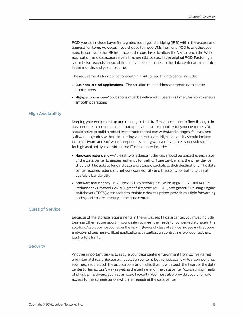
High Availability
Keeping your equipment up and running so that traffic can continue to flow through the
data center is a must to ensure that applications run smoothly for your customers. You
should strive to build a robust infrastructure that can withstand outages, failover, and
software upgrades without impacting your end users. High availability should include
both hardware and software components, along with verification. Key considerations
for high availability in an virtualized IT data center include:
• Hardware redundancy—At least two redundant devices should be placed at each layer
of the data center to ensure resiliency for traffic. If one device fails, the other device
should still be able to forward data and storage packets to their destinations. The data
center requires redundant network connectivity and the ability for traffic to use all
available bandwidth.
• Software redundancy—Features such as nonstop software upgrade, Virtual Router
Redundancy Protocol (VRRP), graceful restart, MC-LAG, and graceful Routing Engine
switchover (GRES) are needed tomaintain device uptime, providemultiple forwarding
paths, and ensure stability in the data center.
Class of Service
Because of the storage requirements in the virtualized IT data center, you must include
lossless Ethernet transport in your design tomeet the needs for converged storage in the
solution.Also, youmust consider thevarying levelsof classof servicenecessary to support
end-to-end business-critical applications, virtualization control, network control, and
best-effort traffic.
Security
Another important task is to secure your data center environment from both external
and internal threats.Because this solutioncontainsbothphysical andvirtual components,
youmust secure both the applications and traffic that flow through the heart of the data
center (oftenacrossVMs)aswell as theperimeter of thedatacenter (consistingprimarily
of physical hardware, such as an edge firewall). Youmust also provide secure remote
access to the administrators who are managing the data center.
13Copyright © 2014, Juniper Networks, Inc.
Chapter 1: Overview

Security requirements for this solution include:
• Perimeter security—Using hardware-based security provides services such as Network
Address Translation (NAT), encrypted tunnels, and intrusion detection to prevent
attacks and prohibit unauthorized access.
• Application security—Use of a software solution for application security provides
network segmentation, robust policies, and intrusion detection.
• Remote access—Implementing a secure access method provides two-factor
authentication and Role-Based Access Control (RBAC) to allow access to authorized
data center administrators.
NetworkManagement
The final challenge is connecting the dots between physical and virtual networking;
bridging this gap enables the data center engineer to quickly troubleshoot and resolve
issues. For network management in a virtualized IT data center, you need to consider
management of fault, configuration, accounting, performance and security (FCAPS) in
your network (Figure 8 on page 14).
Figure 8: Network Management Requirements
For more information about FCAPS (the ISOmodel for network management), see
ISO/IEC 10040.
Network management requirements for the solution include:
• Virtual and physical—Youmust be able tomanage all types of components in the data
center network, regardless if they are hardware-based or virtualized.
• Fault—Errors in the network must be isolated andmanaged in the most efficient way
possible. You should be able to recognize, isolate, correct, and log faults that occur in
your network.
• Configuration—You should be able to provision your network flexibly from a central
location andmanage configurations for the devices in your data center.
• Accounting—Youmust be able to gather network usage statistics, and establish users,
passwords, and permissions.
Copyright © 2014, Juniper Networks, Inc.14
MetaFabric™ Architecture Virtualized Data Center

• Performance—You should be able to themonitor throughput, network response times,
packet loss rates, link utilization, percentage utilization, and error rates to ensure the
network continues to perform at acceptable levels.
• Security—Youmust be able to control access to network components through use of
authorization, encryption, and authentication protocols.
15Copyright © 2014, Juniper Networks, Inc.
Chapter 1: Overview

Copyright © 2014, Juniper Networks, Inc.16
MetaFabric™ Architecture Virtualized Data Center

CHAPTER 2
Design
• Design Considerations on page 17
• Design Scope on page 18
• Design Topology Diagram on page 19
• Design Highlights on page 20
• Solution Design on page 21
• Summary of Key Design Elements on page 58
• Benefits on page 58
Design Considerations
As seen in the Overview, designing a virtualized IT data center requires careful
consideration of the three key segments of compute, network, and storage, along with
their related subareas:
• Compute
• Virtual machines
• Servers
• Hypervisor switch
• Blade switch
• Network
• Access
• Aggregation
• Core switching
• Edge routing
• WAN
• Storage
17Copyright © 2014, Juniper Networks, Inc.

The design must also include careful planning of other architectural considerations:
• Applications
• High availability
• • Class of service
• Security
• Network management
In general, the design for the solutionmust satisfy the following high-level requirements:
• The entire data center must have end-to-end convergence for application traffic of
under one second from the point of view of the application.
• Compute nodes must be able to use all available network links for forwarding.
• Traffic must be able to travel between the points of delivery PODs.
• Virtual resources must be able to bemoved within a POD.
• The out-of-band (OOB)management network must be able to survive the failure of
the data plane within a POD.
Design Scope
This MetaFabric 1.0 solution covers the areas shown in Figure 9 on page 18. Juniper
Networks supplies products that appear in the blue portions of the diagram, while open
ecosystempartner products appear in the black portion. The ecosystempartners for this
solution include IBM (Compute), EMC (Storage), F5 Networks (Services), and VMware
(Virtualization).
Figure 9: Virtualized IT Data Center Ecosystem
Copyright © 2014, Juniper Networks, Inc.18
MetaFabric™ Architecture Virtualized Data Center
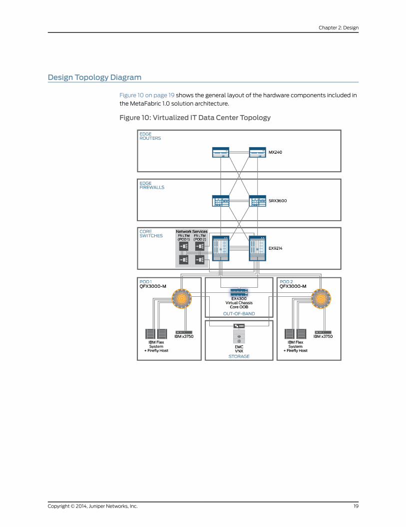
Design Topology Diagram
Figure 10 on page 19 shows the general layout of the hardware components included in
the MetaFabric 1.0 solution architecture.
Figure 10: Virtualized IT Data Center Topology
19Copyright © 2014, Juniper Networks, Inc.
Chapter 2: Design
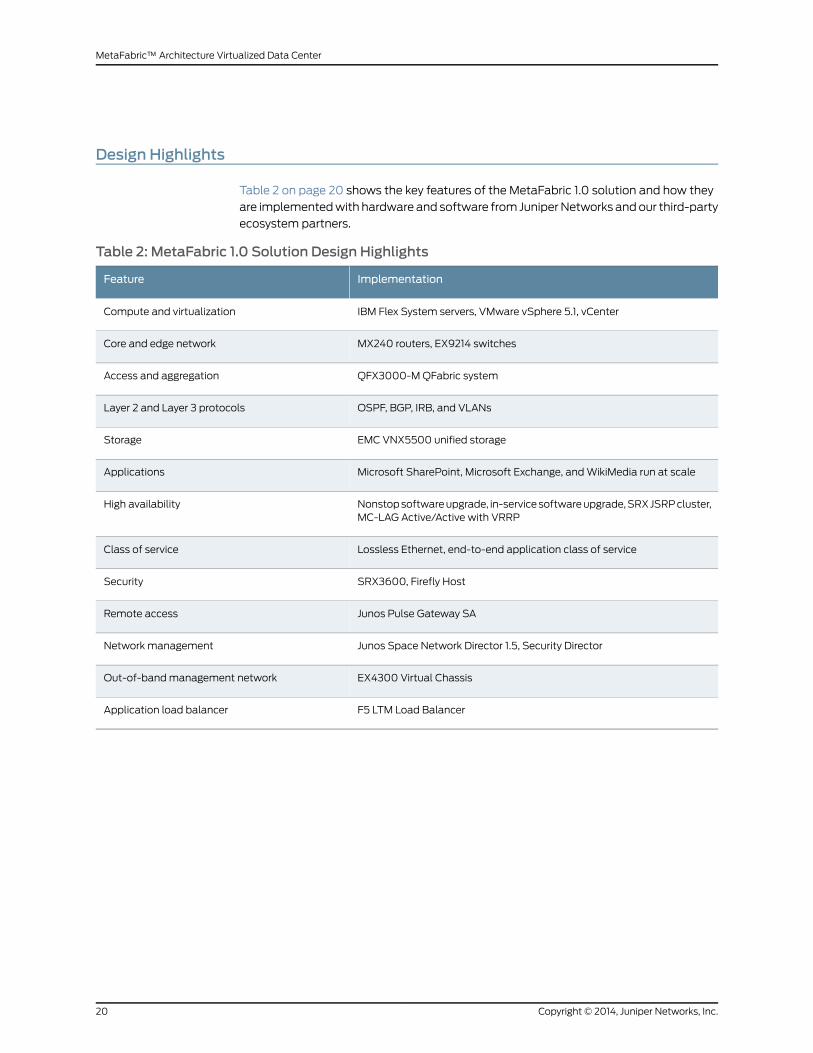
Design Highlights
Table 2 on page 20 shows the key features of the MetaFabric 1.0 solution and how they
are implementedwith hardware and software from JuniperNetworks andour third-party
ecosystem partners.
Table 2: MetaFabric 1.0 Solution Design Highlights
ImplementationFeature
IBM Flex System servers, VMware vSphere 5.1, vCenterCompute and virtualization
MX240 routers, EX9214 switchesCore and edge network
QFX3000-MQFabric systemAccess and aggregation
OSPF, BGP, IRB, and VLANsLayer 2 and Layer 3 protocols
EMC VNX5500 unified storageStorage
Microsoft SharePoint, Microsoft Exchange, andWikiMedia run at scaleApplications
Nonstopsoftwareupgrade, in-servicesoftwareupgrade,SRXJSRPcluster,MC-LAG Active/Active with VRRP
High availability
Lossless Ethernet, end-to-end application class of serviceClass of service
SRX3600, Firefly HostSecurity
Junos Pulse Gateway SARemote access
Junos Space Network Director 1.5, Security DirectorNetwork management
EX4300 Virtual ChassisOut-of-bandmanagement network
F5 LTM Load BalancerApplication load balancer
Copyright © 2014, Juniper Networks, Inc.20
MetaFabric™ Architecture Virtualized Data Center
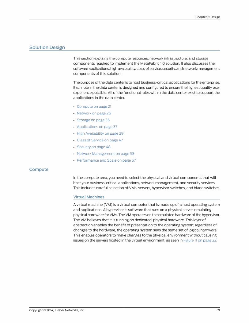
Solution Design
This section explains the compute resources, network infrastructure, and storage
components required to implement the MetaFabric 1.0 solution. It also discusses the
softwareapplications, highavailability, classof service, security, andnetworkmanagement
components of this solution.
The purpose of the data center is to host business-critical applications for the enterprise.
Each role in the data center is designed and configured to ensure the highest quality user
experience possible. All of the functional roleswithin the data center exist to support the
applications in the data center.
• Compute on page 21
• Network on page 26
• Storage on page 35
• Applications on page 37
• High Availability on page 39
• Class of Service on page 47
• Security on page 48
• Network Management on page 53
• Performance and Scale on page 57
Compute
In the compute area, you need to select the physical and virtual components that will
host your business-critical applications, network management, and security services.
This includes careful selection of VMs, servers, hypervisor switches, and blade switches.
Virtual Machines
A virtual machine (VM) is a virtual computer that is made up of a host operating system
and applications. A hypervisor is software that runs on a physical server, emulating
physical hardware forVMs.TheVMoperateson theemulatedhardwareof thehypervisor.
The VM believes that it is running on dedicated, physical hardware. This layer of
abstraction enables the benefit of presentation to the operating system; regardless of
changes to the hardware, the operating system sees the same set of logical hardware.
This enables operators to make changes to the physical environment without causing
issues on the servers hosted in the virtual environment, as seen in Figure 11 on page 22.
21Copyright © 2014, Juniper Networks, Inc.
Chapter 2: Design
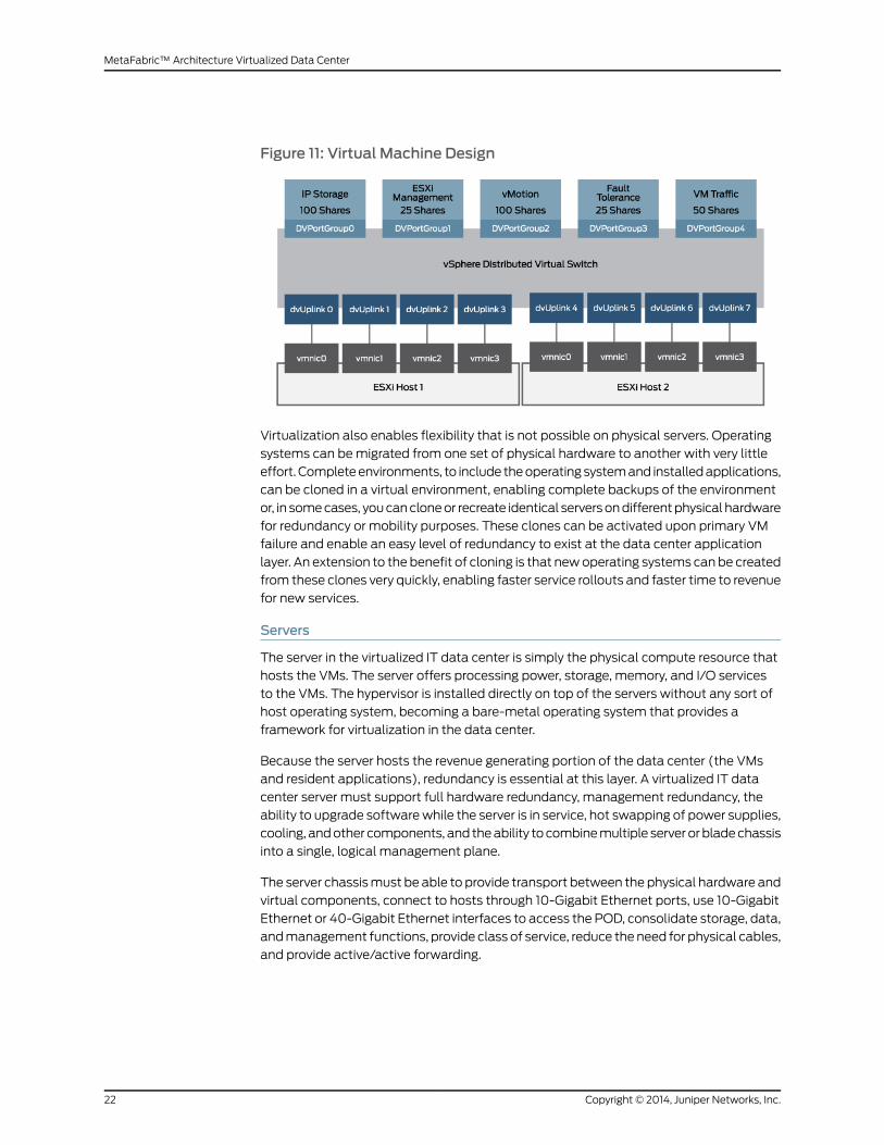
Figure 11: Virtual Machine Design
Virtualization also enables flexibility that is not possible on physical servers. Operating
systems can bemigrated from one set of physical hardware to another with very little
effort. Completeenvironments, to include theoperatingsystemand installedapplications,
can be cloned in a virtual environment, enabling complete backups of the environment
or, in somecases, youcancloneor recreate identical serversondifferentphysical hardware
for redundancy or mobility purposes. These clones can be activated upon primary VM
failure and enable an easy level of redundancy to exist at the data center application
layer. An extension to the benefit of cloning is that newoperating systems can be created
from these clones very quickly, enabling faster service rollouts and faster time to revenue
for new services.
Servers
The server in the virtualized IT data center is simply the physical compute resource that
hosts the VMs. The server offers processing power, storage, memory, and I/O services
to the VMs. The hypervisor is installed directly on top of the servers without any sort of
host operating system, becoming a bare-metal operating system that provides a
framework for virtualization in the data center.
Because the server hosts the revenue generating portion of the data center (the VMs
and resident applications), redundancy is essential at this layer. A virtualized IT data
center server must support full hardware redundancy, management redundancy, the
ability to upgrade softwarewhile the server is in service, hot swapping of power supplies,
cooling, andother components, and theability tocombinemultiple serverorbladechassis
into a single, logical management plane.
The server chassismust be able to provide transport between the physical hardware and
virtual components, connect to hosts through 10-Gigabit Ethernet ports, use 10-Gigabit
Ethernet or 40-Gigabit Ethernet interfaces to access the POD, consolidate storage, data,
andmanagement functions, provide class of service, reduce theneed for physical cables,
and provide active/active forwarding.
Copyright © 2014, Juniper Networks, Inc.22
MetaFabric™ Architecture Virtualized Data Center

Figure 12: Server Design
As seen in Figure 12 on page 23, this solution includes 40-Gigabit Ethernet connections
between QFabric system redundant server Node groups and IBM Flex servers that host
up to 14 blade servers. Other supported connection types include 10-Gigabit Ethernet
oversubscribed ports and 10-Gigabit Ethernet pass-through ports. The solution also has
two built-in switches per Flex server and uses MC-LAG to keep traffic flowing through
the data center.
Hypervisor Switching
The hypervisor switch is the first hop from the application servers in the MetaFabric 1.0
architecture. Virtual machines connect to a distributed virtual switch (dvSwitch) which
is responsible formappinga setof physical network cards (pNICs)acrossa set of physical
hosts into a single logical switch that can be centrally managed by a virtualization
orchestration tool suchasVMware vCenter (Figure 13 onpage 23). ThedvSwitch enables
intra-VM traffic on the same switching domain to pass between the VMs locally without
leaving the blade server or virtual environment. The dvSwitch also acts like a Virtual
Chassis, connectsmultipleESXi hosts simultaneously, andoffersport group functionality
(similar to a VLAN) to provide access between VMs.
Figure 13: VMware Distributed Virtual Switch
This poses an interesting security challenge on the hypervisor switch, as traditional,
appliance-based firewallsdonothavevisibility into thehypervisor switchingenvironment.
23Copyright © 2014, Juniper Networks, Inc.
Chapter 2: Design
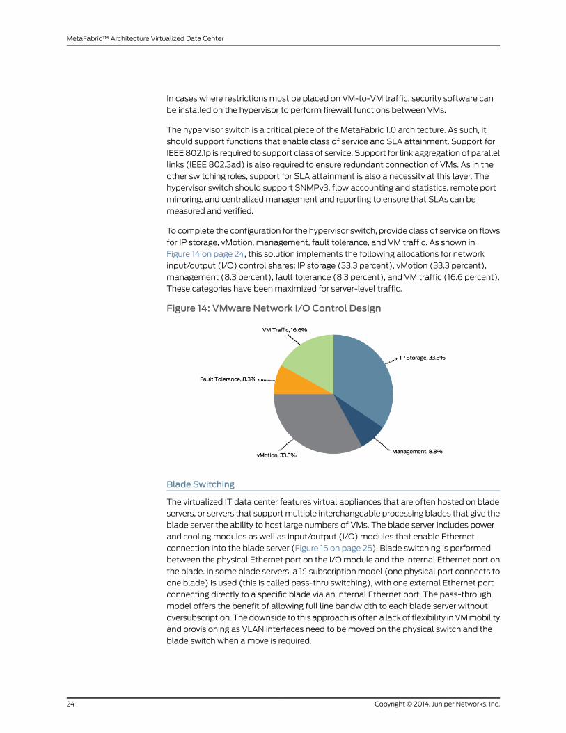
In cases where restrictions must be placed on VM-to-VM traffic, security software can
be installed on the hypervisor to perform firewall functions between VMs.
The hypervisor switch is a critical piece of the MetaFabric 1.0 architecture. As such, it
should support functions that enable class of service and SLA attainment. Support for
IEEE802.1p is required to support class of service. Support for link aggregation of parallel
links (IEEE 802.3ad) is also required to ensure redundant connection of VMs. As in the
other switching roles, support for SLA attainment is also a necessity at this layer. The
hypervisor switch should support SNMPv3, flow accounting and statistics, remote port
mirroring, and centralizedmanagement and reporting to ensure that SLAs can be
measured and verified.
To complete the configuration for the hypervisor switch, provide class of service on flows
for IP storage, vMotion, management, fault tolerance, and VM traffic. As shown in
Figure 14 on page 24, this solution implements the following allocations for network
input/output (I/O) control shares: IP storage (33.3 percent), vMotion (33.3 percent),
management (8.3 percent), fault tolerance (8.3 percent), and VM traffic (16.6 percent).
These categories have beenmaximized for server-level traffic.
Figure 14: VMware Network I/O Control Design
Blade Switching
The virtualized IT data center features virtual appliances that are often hosted on blade
servers, or servers that supportmultiple interchangeable processing blades that give the
blade server the ability to host large numbers of VMs. The blade server includes power
and cooling modules as well as input/output (I/O) modules that enable Ethernet
connection into the blade server (Figure 15 on page 25). Blade switching is performed
between the physical Ethernet port on the I/Omodule and the internal Ethernet port on
the blade. In some blade servers, a 1:1 subscriptionmodel (one physical port connects to
one blade) is used (this is called pass-thru switching), with one external Ethernet port
connecting directly to a specific blade via an internal Ethernet port. The pass-through
model offers the benefit of allowing full line bandwidth to each blade server without
oversubscription. Thedownside to this approach is oftena lackof flexibility inVMmobility
and provisioning as VLAN interfaces need to bemoved on the physical switch and the
blade switch when amove is required.
Copyright © 2014, Juniper Networks, Inc.24
MetaFabric™ Architecture Virtualized Data Center

Figure 15: Sample Blade Switch, Rear View
Another mode of blade switch operation is where the blade switch enables
oversubscription to the blade servers. In this type of blade server, there may be only 4
external ports that connect internally to 12 separate blade servers. This would result in
3:1 oversubscription (three internal ports to every one external port). The benefit to this
mode of operation is that it minimizes the number of connected interfaces and access
switch cabling per blade server, even though the performance of oversubscribed links
and their connected VMs can degrade as a result. While this architecture is designed for
data centers that utilize blade servers, the design works just as well in data centers that
do not utilize blade servers to host VMs.
Table 3 on page 26 shows that both pass-through blade servers and oversubscribed
blade servers are acceptable choices for this solution in your data center network. In
some cases, youmight need the faster speed provided by the 40-Gigabit Ethernet
connections to support newer equipment, while in others you would prefer the line-rate
performance offered by a pass-through switch. As a result, all three blade server types
are supported in this design.
25Copyright © 2014, Juniper Networks, Inc.
Chapter 2: Design
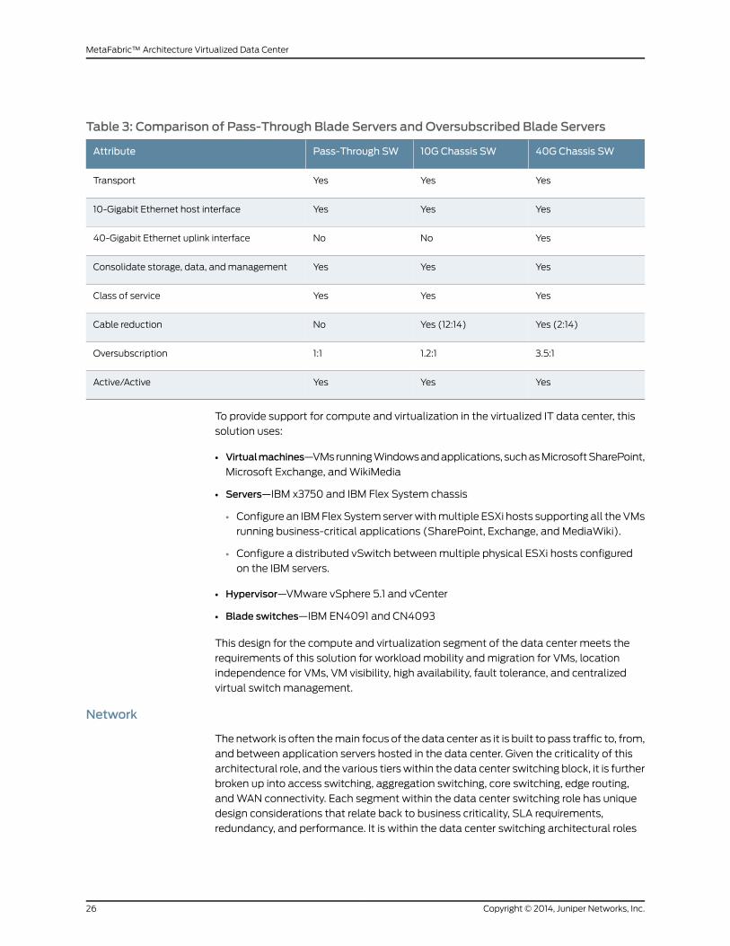
Table 3: Comparison of Pass-Through Blade Servers and Oversubscribed Blade Servers
40G Chassis SW10G Chassis SWPass-Through SWAttribute
YesYesYesTransport
YesYesYes10-Gigabit Ethernet host interface
YesNoNo40-Gigabit Ethernet uplink interface
YesYesYesConsolidate storage, data, andmanagement
YesYesYesClass of service
Yes (2:14)Yes (12:14)NoCable reduction
3.5:11.2:11:1Oversubscription
YesYesYesActive/Active
To provide support for compute and virtualization in the virtualized IT data center, this
solution uses:
• Virtualmachines—VMsrunningWindowsandapplications, suchasMicrosoftSharePoint,
Microsoft Exchange, andWikiMedia
• Servers—IBM x3750 and IBM Flex System chassis
• Configure an IBMFlex Systemserverwithmultiple ESXi hosts supporting all theVMs
running business-critical applications (SharePoint, Exchange, and MediaWiki).
• Configure a distributed vSwitch betweenmultiple physical ESXi hosts configured
on the IBM servers.
• Hypervisor—VMware vSphere 5.1 and vCenter
• Blade switches—IBM EN4091 and CN4093
This design for the compute and virtualization segment of the data center meets the
requirements of this solution for workloadmobility andmigration for VMs, location
independence for VMs, VM visibility, high availability, fault tolerance, and centralized
virtual switch management.
Network
The network is often themain focus of the data center as it is built to pass traffic to, from,
and between application servers hosted in the data center. Given the criticality of this
architectural role, and the various tierswithin the data center switching block, it is further
broken up into access switching, aggregation switching, core switching, edge routing,
andWAN connectivity. Each segment within the data center switching role has unique
design considerations that relate back to business criticality, SLA requirements,
redundancy, and performance. It is within the data center switching architectural roles
Copyright © 2014, Juniper Networks, Inc.26
MetaFabric™ Architecture Virtualized Data Center

that the network must be carefully designed to ensure that your data center equipment
purchases maximize network scale and performance while minimizing costs.
Access and Aggregation
The access layer consists of physical switches that connect to servers and end hosts.
Access switching typically focuses on implementing Layer 2 switches, but can include
Layer 3 components (such as IRB) to supportmore robust VMmobility. Access switching
should also support high availability. In a multi-chassis or virtual chassis environment,
where multiple physical switches can be combined to form a single, logical switch,
redundancy can be achieved at the access layer. This type of switch architecture is built
with control plane redundancy, MC-LAG, and the ability to upgrade individual switches
while they are in service. Additionally, the access switching role should support storage
traffic, or the ability to pass data traffic over Ethernet via iSCSI and Fiber Channel over
Ethernet (FCoE). Data Center Bridging (DCB) should also be supported by the access
switching role to enable full support of storage traffic. Within DCB, support for
priority-based flow control (PFC), enhanced transmission selection (ETS), and data
center bridging exchange (DCBX) should also be supported as these features enable
storage traffic to pass properly between all servers and storage devices within a data
center segment.
The aggregation switch acts as amultiplexing point between the access and the core of
the data center. The aggregation architectural role serves to combine a large number of
smaller interfaces from the access into high bandwidth trunk ports that can bemore
easily consumed by the core switch. Redundancy should be a priority in the design of the
aggregation role as all Layer 2 flows between the data center and the core switch are
combined and forwarded by the data center aggregation switch role. At this layer, a
switching architecture that supports the combination of multiple switches into a single,
logical systemwith control and forwarding plane redundancy is recommended. This
switchingarchitectureenables redundancy featuressuchasMC-LAG, loop-free redundant
paths, and in-service software upgrades to enable data center administrators to
consistently meet and exceed SLAs.
One recommendation is to combine the access and aggregation layers of your network
by using a QFabric system. Not only does a QFabric system offer a single point of
provisioning,management, and troubleshooting for thenetworkoperator, it alsocollapses
switching tiers for any-to-any connectivity, provides lower latency, andenables all access
devices to be only one hop away from one another, as shown in Figure 16 on page 28.
27Copyright © 2014, Juniper Networks, Inc.
Chapter 2: Design

Figure 16: Juniper Networks QFabric Systems Enable a Flat Data CenterNetwork
To implement the access and aggregation switching portions of the virtualized IT data
center, this solutionuses theQFX3000-MQFabric system.Thereare twoQFabric systems
(POD1 and POD2) in this solution to provide performance and scale. The QFabric PODs
support 768 ports per POD and feature low port-to-port latency, a single point of
management per POD, and lossless Ethernet to support storage traffic. The use of
predefined POD configurations enables the enterprise to more effectively plan data
center rollouts by offering predictable growth and scale in the solution architecture. Key
configuration steps include:
• Configure the QFX3000-MQFabric systems with 3 redundant server Node groups
(RSNGs) connected to 2 IBM Flex System blade servers to deliver application traffic.
• The first IBM Flex System server uses a 40-Gigabit Ethernet converged network
adapter (CNA) connected to a QFabric system RSNG containing QFX3600 Node
devices (RSNG4).
• The second IBM Flex System server has 10-Gigabit Ethernet pass throughmodules
connected to RSNG2 and RSNG3 on the second QFabric system.
• Connect the EMC VNX storage platform to the QFabric systems for storage access
using iSCSI and NFS.
• Connect the QFabric systems with the EX9214 core switch by way of a network Node
group containing 2 Node devices which use four 24-port LAGs configured as trunk
ports.
• ConfigureOSPF in thePODs (within theQFabric systemnetworkNodegroup) towards
the EX9214 core switch andplace these connections in Area10 as a totally stubby area.
Core Switching
The core switch is often configured as a Layer 3 device that handles routing between
various Layer 2 domains in the data center. A robust implementation of the core switch
in the virtualized IT data center will support both Layer 2 and Layer 3 to enable a full
range of interoperability and service provisioning in amultitenant environment.Much like
in the edge role, the redundancy of core switching is critical as it too is a traffic congestion
Copyright © 2014, Juniper Networks, Inc.28
MetaFabric™ Architecture Virtualized Data Center

pointbetween thecustomerand theapplication.Aproperlydesigneddatacenter includes
a fully redundant core switch layer that supports a wide range of interfaces (1-Gigabit,
10-Gigabit, 40-Gigabit, and 100-Gigabit Ethernet) with high density. The port density in
the core switching role is a critical factor as the data center core should be designed to
support futureexpansionwithout requiringnewhardware (beyond linecardsand interface
adapters). The core switch role should also support a wide array of SLA statistics
collection, andshouldbeservice-aware tosupport collectionof service-chainingstatistics.
The general location of the core switching function in this solution is shown in
Figure 17 on page 29.
Figure 17: Core Switching
Table 4 on page 30 shows some of the reasons for choosing an EX9200 switch over an
EX8200switch toprovide core switching capabilities in this solution. TheEX9200switch
providesa significantly larger numberof 10-Gigabit Ethernetports, support for 40-Gigabit
Ethernetports, ability tohostmoreanalyzer sessions, firewall filters, andBFDconnections,
and critical support for in-service software upgrade (ISSU) andMC-LAG. These reasons
make the EX9200 switch the superior choice in this solution.
29Copyright © 2014, Juniper Networks, Inc.
Chapter 2: Design
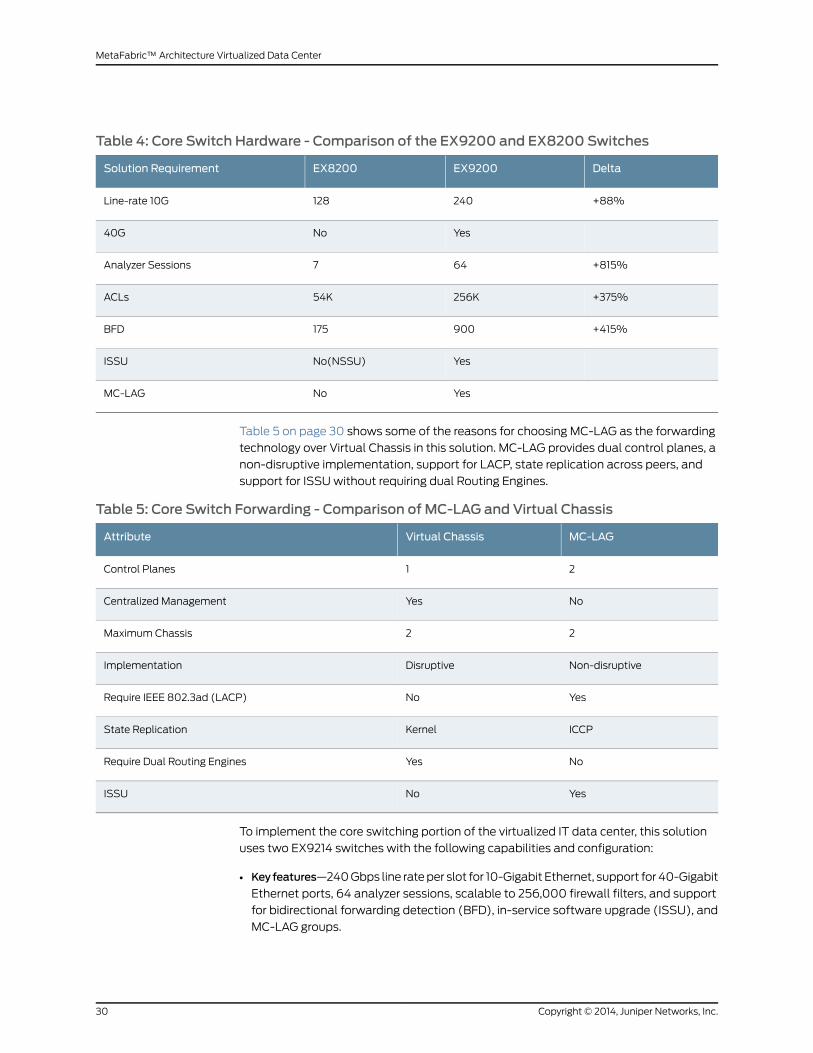
Table 4: Core Switch Hardware - Comparison of the EX9200 and EX8200 Switches
DeltaEX9200EX8200Solution Requirement
+88%240128Line-rate 10G
YesNo40G
+815%647Analyzer Sessions
+375%256K54KACLs
+415%900175BFD
YesNo(NSSU)ISSU
YesNoMC-LAG
Table 5 on page 30 shows some of the reasons for choosing MC-LAG as the forwarding
technology over Virtual Chassis in this solution. MC-LAG provides dual control planes, a
non-disruptive implementation, support for LACP, state replication across peers, and
support for ISSUwithout requiring dual Routing Engines.
Table 5: Core Switch Forwarding - Comparison of MC-LAG and Virtual Chassis
MC-LAGVirtual ChassisAttribute
21Control Planes
NoYesCentralized Management
22Maximum Chassis
Non-disruptiveDisruptiveImplementation
YesNoRequire IEEE 802.3ad (LACP)
ICCPKernelState Replication
NoYesRequire Dual Routing Engines
YesNoISSU
To implement the core switching portion of the virtualized IT data center, this solution
uses two EX9214 switches with the following capabilities and configuration:
• Keyfeatures—240Gbps line rateper slot for 10-Gigabit Ethernet, support for 40-Gigabit
Ethernet ports, 64 analyzer sessions, scalable to 256,000 firewall filters, and support
for bidirectional forwarding detection (BFD), in-service software upgrade (ISSU), and
MC-LAG groups.
Copyright © 2014, Juniper Networks, Inc.30
MetaFabric™ Architecture Virtualized Data Center
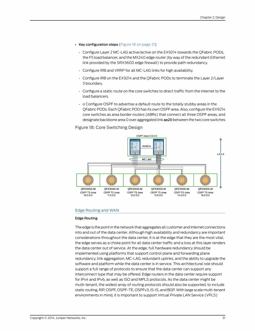
• Key configuration steps (Figure 18 on page 31)
• Configure Layer 2 MC-LAG active/active on the EX9214 towards the QFabric PODs,
the F5 load balancer, and theMX240 edge router (byway of the redundant Ethernet
link provided by the SRX3600 edge firewall) to provide path redundancy.
• Configure IRB and VRRP for all MC-LAG links for high availability.
• Configure IRB on the EX9214 and the QFabric PODs to terminate the Layer 2/Layer
3 boundary.
• Configure a static route on the core switches to direct traffic from the Internet to the
load balancers.
• o Configure OSPF to advertise a default route to the totally stubby areas in the
QFabric PODs. EachQFabric PODhas its ownOSPFarea. Also, configure the EX9214
core switches as area border routers (ABRs) that connect all three OSPF areas, and
designatebackbonearea0over aggregated linkae20between the twocore switches
Figure 18: Core Switching Design
Edge Routing andWAN
Edge Routing
Theedge is thepoint in thenetwork thataggregatesall customerand Internet connections
into and out of the data center. Although high availability and redundancy are important
considerations throughout the data center, it is at the edge that they are the most vital;
the edge serves as a choke point for all data center traffic and a loss at this layer renders
the data center out of service. At the edge, full hardware redundancy should be
implemented using platforms that support control plane and forwarding plane
redundancy, link aggregation, MC-LAG, redundant uplinks, and the ability to upgrade the
software and platformwhile the data center is in service. This architectural role should
support a full range of protocols to ensure that the data center can support any
interconnect type that may be offered. Edge routers in the data center require support
for IPv4 and IPv6, as well as ISO and MPLS protocols. As the data center might be
multi-tenant, the widest array of routing protocols should also be supported, to include
static routing,RIP,OSPF,OSPF-TE,OSPFv3, IS-IS, andBGP.With large scalemulti-tenant
environments in mind, it is important to support Virtual Private LAN Service (VPLS)
31Copyright © 2014, Juniper Networks, Inc.
Chapter 2: Design
through the support of bridge domains, overlapping VLAN IDs, integrated routing and
bridging (IRB), and IEEE802.1Q(QinQ).Theedgeshould support acomplete setofMPLS
VPNs, includingL3VPN, L2VPN(RFC4905andRFC6624, orMartini andKompelladrafts,
respectively), and VPLS.
Network Address Translation (NAT) is another factor to consider when designing the
data center edge. It is likely thatmultiple customers serviced by the data center will have
overlapping private network address schemes. In environments where direct Internet
access to the data center is enabled, NAT is required to translate routable, public IP
addresses to the private IP addressing used in the data center. The edgemust support
Basic NAT 44, NAPT44, NAPT66, Twice NAT44, and NAPT-PT.
Finally, as the edge is the ingress and egress point of the data center, the implementation
should support robust data collection to enable administrators to verify and prove strict
service-level agreements (SLAs) with their customers. The edge layer should support
collection of average traffic flows and statistics, and at a minimum should support the
ability to report exact traffic statistics to include the exact number of bytes and packets
that were received, transmitted, queued, lost, or dropped, per application.
Figure 19 on page 33 shows the location of the edge routing function in this solution.
Copyright © 2014, Juniper Networks, Inc.32
MetaFabric™ Architecture Virtualized Data Center
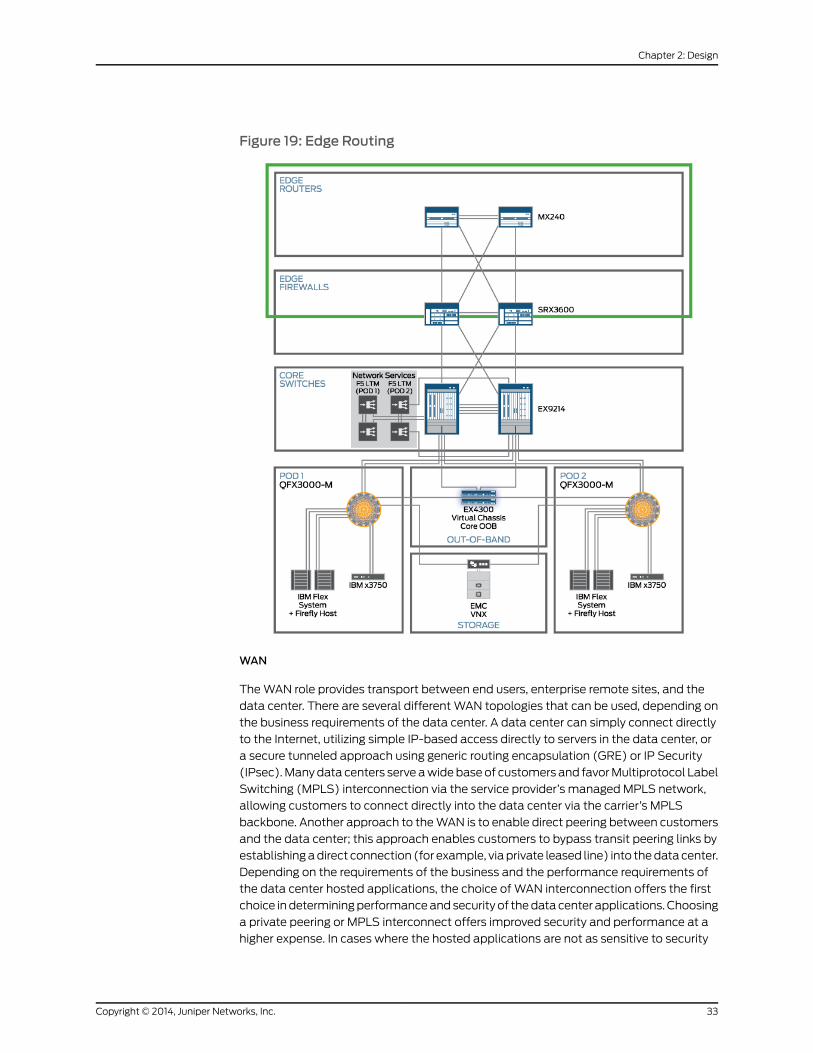
Figure 19: Edge Routing
WAN
TheWAN role provides transport between end users, enterprise remote sites, and the
data center. There are several differentWAN topologies that can be used, depending on
the business requirements of the data center. A data center can simply connect directly
to the Internet, utilizing simple IP-based access directly to servers in the data center, or
a secure tunneled approach using generic routing encapsulation (GRE) or IP Security
(IPsec).Manydata centers serve awidebaseof customers and favorMultiprotocol Label
Switching (MPLS) interconnection via the service provider’s managed MPLS network,
allowing customers to connect directly into the data center via the carrier’s MPLS
backbone. Another approach to theWAN is to enable direct peering between customers
and the data center; this approach enables customers to bypass transit peering links by
establishingadirect connection (for example, viaprivate leased line) into thedatacenter.
Depending on the requirements of the business and the performance requirements of
the data center hosted applications, the choice ofWAN interconnection offers the first
choice indeterminingperformanceandsecurity of thedatacenter applications. Choosing
a private peering or MPLS interconnect offers improved security and performance at a
higher expense. In cases where the hosted applications are not as sensitive to security
33Copyright © 2014, Juniper Networks, Inc.
Chapter 2: Design

and performance, or where application protocols offer built-in security, a simple Internet
connected data center can offer an appropriate level of security and performance at a
lower cost.
To implement the edge routing andWAN portions of the virtualized IT data center, this
solution uses MX240 Universal Edge routers. Because the MX240 router offers dual
Routing Engines and ISSU at a reasonable price point, it is the preferred option over the
smaller MX80 router. The key connection and configuration steps are:
• Connect the MX240 edge routers to the service provider networks to provide Internet
access to the data center.
• Configure the two edge routers to be EBGP peers with 2 service providers to provide
redundant Internet connections.
• Configure IBGP between the 2 edge routers and applying a next-hop self export policy.
• Configure BGP local preference on the primary service provider to offer a preferred exit
point to the Internet.
• Export a dynamic, condition-based, default route to the Internet into OSPF on both
edge routers toward the edge firewalls and core switches to provide Internet access
for the virtualized IT data center devices (Figure 20 on page 34).
• Configure both edge routers in Area 1 for OSPF.
• Enable Network Address Translation (NAT) to convert private IP addresses into public
IP addresses.
Figure 20: Edge Routing Design
This design for the network segment of the data center meets the requirements of this
solution for 1-Gigabit, 10-Gigabit, and 40-Gigabit Ethernet ports, converged data and
storage, load balancing, quality of experience, network segmentation, traffic isolation
and separation, and time synchronization.
Copyright © 2014, Juniper Networks, Inc.34
MetaFabric™ Architecture Virtualized Data Center
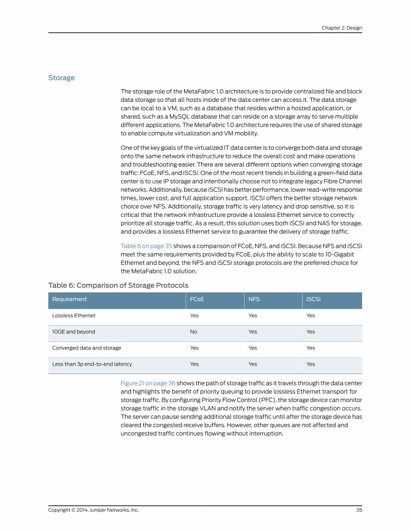
Storage
The storage role of theMetaFabric 1.0 architecture is to provide centralized file and block
data storage so that all hosts inside of the data center can access it. The data storage
can be local to a VM, such as a database that resides within a hosted application, or
shared, such as a MySQL database that can reside on a storage array to serve multiple
different applications. TheMetaFabric 1.0 architecture requires the use of shared storage
to enable compute virtualization and VMmobility.
One of the key goals of the virtualized IT data center is to converge both data and storage
onto the same network infrastructure to reduce the overall cost andmake operations
and troubleshooting easier. There are several different options when converging storage
traffic: FCoE, NFS, and iSCSI. One of themost recent trends in building a green-field data
center is to use IP storage and intentionally choose not to integrate legacy Fibre Channel
networks.Additionally, because iSCSIhasbetterperformance, lower read-write response
times, lower cost, and full application support, iSCSI offers the better storage network
choice over NFS. Additionally, storage traffic is very latency and drop sensitive, so it is
critical that the network infrastructure provide a lossless Ethernet service to correctly
prioritize all storage traffic. As a result, this solution uses both iSCSI and NAS for storage,
and provides a lossless Ethernet service to guarantee the delivery of storage traffic.
Table 6onpage 35 showsa comparison of FCoE, NFS, and iSCSI. BecauseNFSand iSCSI
meet the same requirements provided by FCoE, plus the ability to scale to 10-Gigabit
Ethernet and beyond, the NFS and iSCSI storage protocols are the preferred choice for
the MetaFabric 1.0 solution.
Table 6: Comparison of Storage Protocols
iSCSINFSFCoERequirement
YesYesYesLossless Ethernet
YesYesNo10GE and beyond
YesYesYesConverged data and storage
YesYesYesLess than 3p end-to-end latency
Figure 21 onpage36 shows thepathof storage traffic as it travels through thedata center
and highlights the benefit of priority queuing to provide lossless Ethernet transport for
storage traffic. By configuringPriority FlowControl (PFC), the storage device canmonitor
storage traffic in the storage VLAN and notify the server when traffic congestion occurs.
The server can pause sending additional storage traffic until after the storage device has
cleared the congested receive buffers. However, other queues are not affected and
uncongested traffic continues flowing without interruption.
35Copyright © 2014, Juniper Networks, Inc.
Chapter 2: Design

Figure 21: Storage Lossless Ethernet Design
The packet flow for storage traffic is as follows:
1. The server transmits storage traffic to the QFabric system.
2. The QFabric system classifies the traffic.
3. Traffic is queued according to priority.
4. The QFabric system transmits the traffic to the storage array.
5. The storage array receives the traffic.
6. The storage array transmits traffic back to the QFabric system.
7. The QFabric system classifies the traffic.
8. Traffic is queued according to priority.
9. The QFabric system transmits the traffic to the servers and VMs.
10. The server receives the traffic.
To implement the storage portion of the virtualized IT data center, this solution uses EMC
VNX5500 unified storage with a single storage array. This storage is connected to the
QFabric PODs, which in turn connect to the servers and VMs, as seen in
Figure 22 on page 37. The design assumes that the data center architect wishes to save
on cost initially by sharing a single storage array with multiple QFabric PODs. However,
the design can evolve to allocating one storage array per oneQFabric POD, as usage and
demand warrant such expansion.
Copyright © 2014, Juniper Networks, Inc.36
MetaFabric™ Architecture Virtualized Data Center

Figure 22: Storage Design
This solution also implements Data Center Bridging (DCB) to enable full support of
storage traffic. Within DCB, support for priority-based flow control (PFC), enhanced
transmission selection (ETS), and Data Center Bridging Capability Exchange (DCBX)
enables storage traffic to pass properly between all servers and storage devices within
a data center segment and to deliver a lossless Ethernet environment.
This design for the storage segment of the virtualized IT data center meets the
requirements of this solution for scale, lossless Ethernet, the ability to boot from shared
storage, and support for multiple protocol storage.
Applications
Applications in the virtualized IT data center are built as Virtual Machines (VMs) and are
hosted on servers, or physical compute resources that reside on the blade server. This
design for applications meets the requirements of this solution for business-critical
applications and high performance.
The MetaFabric 1.0 solution supports a complete software stack that covers four major
application categories: computemanagement, networkmanagement, network services,
and business-critical applications (Figure 23 on page 38). These applications run on top
of IBM servers and VMware vSphere 5.1.
37Copyright © 2014, Juniper Networks, Inc.
Chapter 2: Design

Figure 23: Virtualized IT Data Center Solution Software Stack
ComputeManagement
VMware vCenter is a virtualizationmanagement platform that offers centralized control
and visibility into compute, storage, and networking resources. Data center operators
use the de facto, industry-standard vCenter on a daily basis to manage and provision
VMs. VMware vCloud Director allows the data center manager to create an in-house
cloud service and partition the virtualization environment into segments that can be
administered by separate business units or administrative entities. The pool of resources
can now be partitioned into virtual data centers which can offer their own independent
virtualization services. Use of vCenter and vCloud Director offers the first element of
software application support for the MetaFabric 1.0 solution.
NetworkManagement
The MetaFabric 1.0 solution uses Junos Space Management Applications to provide
networkprovisioning, orchestration, and inventorymanagement. Theapplications include
Network Director for management of wired and wireless data center networks, and
Security Director for security policy administration.
Network Services
Network load balancing is a common network service. There are twomethods to provide
network load balancing: virtual and hardware-based. The virtual load balancer operates
in thehypervisor asaVM.Oneof thebenefits of a virtual loadbalancer is rapidprovisioning
of additional load-balancing power. Another benefit is that the administration of the
virtual loadbalancer canbedelegated toanother administrative entitywithout impacting
other applications and traffic.
However the drawback to a virtual load balancer is that the performance is limited to
the number of compute resources that are available. Hardware load balancers offer
muchmore performance in traffic throughput and SSL encryption and decryption with
dedicated security hardware.
The MetaFabric 1.0 solution uses the local traffic manager (LTM) from F5 Networks.
Copyright © 2014, Juniper Networks, Inc.38
MetaFabric™ Architecture Virtualized Data Center
The load balancers provide the following services:
• Advertise the existence of the application
• Distribute the traffic across a set of servers.
• Leverage features such as SSL acceleration and compression.
• Provide additional Layer 7 features.
Business-Critical Applications
Software applications are made of multiple server tiers; the most common areWeb,
application, anddatabase servers. Each server has its owndiscrete set of responsibilities.
TheWeb tier handles the interaction with the users and the application. The application
tier handles all of the application logic and programming. The database tier handles all
of the data storage and application inventory.
The following software applications were tested as part of the MetaFabric 1.0 solution:
• Microsoft SharePoint
The SharePoint application requires three tiers: Web, application, and database. The
Web tier usesMicrosoft IIS to handleWeb tracking and interactionwith end users. The
application tier uses Microsoft SharePoint and Active Directory to provide the file
sharing and content management software. Finally, the database tier uses Microsoft
SQL Server to store and organize the application data.
• Microsoft Exchange
TheExchangeapplication requires two tiers: aWeb tier, andasecond tier that combines
the application and the database into a single tier.
• MediaWiki Application
The MediaWiki application requires two tiers: a combinedWeb and application tier,
and a database tier. Apache httpd is combinedwith the hypertext preprocessor (PHP)
to render and present the application, while the data is stored on the database tier
with MySQL.
High Availability
Thisdesignmeets thehighavailability requirementsofhardware redundancyandsoftware
redundancy.
Hardware Redundancy
To provide hardware redundancy in the virtualized IT data center, this solution uses:
• Redundant server hardware—Two IBM 3750 standalone servers and two IBM Pure Flex
System Chassis
• Redundant access and aggregation PODs—TwoQFX3000-MQFabric systems
• Redundant core switches—Two EX9214 switches
• Redundant edge firewalls—Two SRX3600 Services Gateways
39Copyright © 2014, Juniper Networks, Inc.
Chapter 2: Design

• Redundant edge routers—TwoMX240 Universal Edge routers
• Redundant storage—Two EMC VNX5500 unified storage
• Redundant load balancers—Two F5 LTM 4200v load balancers
• Out-of-bandmanagement switches use Virtual Chassis technology—Four EX4300
switches
Software Redundancy
To provide software redundancy in the virtualized IT data center, this solution uses:
• Graceful restart—Helper routers assist restarting devices in restoring routing protocols,
state, and convergence.
• Graceful Routing Engine switchover—Keeps the operating system state synchronized
between themaster and backup Routing Engines in a Juniper Network device.
• In-service software upgrade(for the core switches and edge routers)—Enables the
network operating system to be upgraded without downtime.
• MC-LAG—Enables aggregated Ethernet interface bundles to contain interfaces from
more than one device.
• Nonstop active routing—Keeps the Layer 3 protocol state synchronized between the
master and backup Routing Engines.
• Nonstop bridging—Keeps the Layer 2 protocol state synchronized between themaster
and backup Routing Engines.
• Nonstopsoftwareupgrade—(for theQFX3000-MQFabric systemPODs)—Enables the
network operating system to be upgraded with minimal impact to forwarding.
• Virtual Router Redundancy Protocol (VRRP)—Provides a virtual IP address for traffic
and forwards the traffic to one of two peer routers, depending on which one is
operational.
MC-LAGDesign Considerations
To allow all the links to forward traffic without using Spanning Tree Protocol (STP), you
can configureMC-LAG on edge routers and core switches. The edge routers useMC-LAG
toward the edge firewalls, and the core switches useMC-LAG toward eachQFabric POD,
application load balancer (F5), and out-of-band (OOB)management switch.
Multichassis link aggregation group (MC-LAG) is a feature that supports aggregated
Ethernet bundles spreadacrossmore thanonedevice. LinkAggregationControl Protocol
(LACP) supportsMC-LAGand is used for dynamic configuration andmonitoring on links.
The available options for MC-LAG include Active/Standby (where one device is active
and the other assists if the active device fails) or Active/Active (where both devices
actively participate in the MC-LAG connection).
For this solution, MC-LAG Active/Active is preferred because it provides link-level and
node-level protection for Layer 2 networks and Layer 2/Layer 3 combined hybrid
environments.
Copyright © 2014, Juniper Networks, Inc.40
MetaFabric™ Architecture Virtualized Data Center

Highlights of MC-LAG Active/Active
MC-LAG Active/Active has the following characteristics:
• Both core switches have active aggregated Ethernet member interfaces and forward
the traffic. If one of the core switches fails, the other core switchwill forward the traffic.
Traffic is load balanced by default, so link-level efficiency is 100 percent.
• The Active/Active method has faster convergence than the Active/Standbymethod.
Fastconvergenceoccursbecause information isexchangedbetweenthe routersduring
operations. After a failure, the remaining operational core switch does not need to
relearn any routes and continues to forward the traffic.
• Routing protocols (such as OSPF) can be used over MC-LAG/IRB interfaces for Layer
3 termination.
• If you configure Layer 3 protocols in the core, you can use an integrated routing and
bridging (IRB) interface to offer a hybrid Layer 2 and Layer 3 environment at the core
switch.
• Active/Active also offers maximum utilization of resources and end-to-end load
balancing.
To extend a link aggregation group (LAG) across two devices (MC-LAG):
• Both devices need to synchronize their aggregated Ethernet LACP configurations
• Learned MAC address and ARP entries must be synchronized.
The above MC-LAG requirements are achieved by using the following
protocols/mechanisms as shown in Figure 24 on page 41:
1. Interchassis Control Protocol (ICCP)
2. Interchassis Link Protection Link (ICL-PL)
Figure 24: MC-LAG – ICCP and ICL Design
41Copyright © 2014, Juniper Networks, Inc.
Chapter 2: Design

1. ICCP
• ICCP is a control plane protocol for MC-LAG. It uses TCP as a transport protocol
and Bidirectional Forwarding Detection (BFD) for fast convergence. When you
configure ICCP, youmust also configure BFD.
• ICCP synchronizes configurations and operational states between the twoMC-LAG
peers.
• ICCP also synchronizes MAC address and ARP entries learned from one MC-LAG
node and shares themwith the other peer.
• • Peering with the ICCP peer loopback IP address is recommended to avoid any
direct link failurebetweenMC-LAGpeers.As longas the logical connectionbetween
the peers remains up, ICCP stays up.
• Although you can configure ICCP on either a single link or an aggregated bundle
link, an aggregated Ethernet LAG is preferred.
• • You can also configure ICCP and ICL links on a single aggregated Ethernet bundle
undermultiple logical interfacesusing flexibleVLANtagging supportedonMXSeries
platforms.
2. ICL-PL
• ICL is a special layer 2 link for Active-Active only between the MC-LAG peers
• ICL-PL is needed to protect connectivity of MC-LAG in case of failure of all core
facing links corresponding to one MC-LAG node.
• If the traffic receiver is single homed to one of the MC-LAG nodes (N1), ICL is used
to forward thepackets receivedbywayof theMC-LAG interface to theotherMC-LAG
nodes (N2).
• Split horizon is enabled to avoid loop on the ICL
• There is no data plane MAC learning over ICL.
MC-LAG Specific Configuration Parameters
Redundancy group ID—ICCP uses a redundancy group to associate multiple chassis that
performsimilar redundancy functions.A redundancygroupestablishesacommunication
channel so that applications on ICCP peers can reach each other. A redundancy group
ID is similar to a mesh group identifier.
MC-AE ID—Themulti-chassis aggregated Ethernet (MC-AE) ID is a per-multi-chassis
interface. For example, if one MC-AE interface is spread across multiple core switches,
you should assign the same redundancy group ID. When an application wants to send a
message to a particular redundancy group, the application provides the information and
ICCP delivers it to the members of that redundancy group.
Service ID—Anewservice IDobject for bridgedomainsoverridesanyglobal switchoptions
configuration for the bridge domain. The service ID is unique across the entire network
for agivenservice toallowcorrect synchronization. For example, a service IDsynchronizes
applications like IGMP, ARP, andMACaddress learning for a given service across the core
Copyright © 2014, Juniper Networks, Inc.42
MetaFabric™ Architecture Virtualized Data Center

switches. (Note: Both MC-LAG peers must share the same service ID for a given bridge
domain.)
MC-LAG Active/Active Layer 3 Routing Features
MC-LAGActive/Active is a Layer 2 logical link. IRB interfaces are used to create integrated
Layer 2 and Layer 3 links. As a result, you have two design options when assigning IP
addresses across MC-LAG peers:
• Option 1: VRRPMC-LAGActive/Active provides common virtual IP andMACaddresses
and unique physical IP and MAC addresses. Both address types are needed if you
configure routing protocols on MC-LAG Active/Active interfaces. The VRRP data
forwarding logic has beenmodified in Junos OS if you configure both MC-LAG
Active/ActiveandVRRP.Whenconfiguredsimultaneously, both theMC-LAGandVRRP
peers forward traffic and load-balance the traffic between them, as shown in
Figure 25 on page 43.
Figure 25: VRRP andMC-LAG – Active/Active Option
Data packets received by the backup VRRP peer on the MC-LAGmember link are
forwarded to the core link without sending them to themaster VRRP peer.
• Option 2: MAC address synchronization Figure 26 on page 44 provides a unique IP
address per peer, but shares a MAC address between the MC-LAG peers. You should
use option 2 if you do not plan to configure routing protocols on the MC-LAG
Active/Active interfaces.
43Copyright © 2014, Juniper Networks, Inc.
Chapter 2: Design
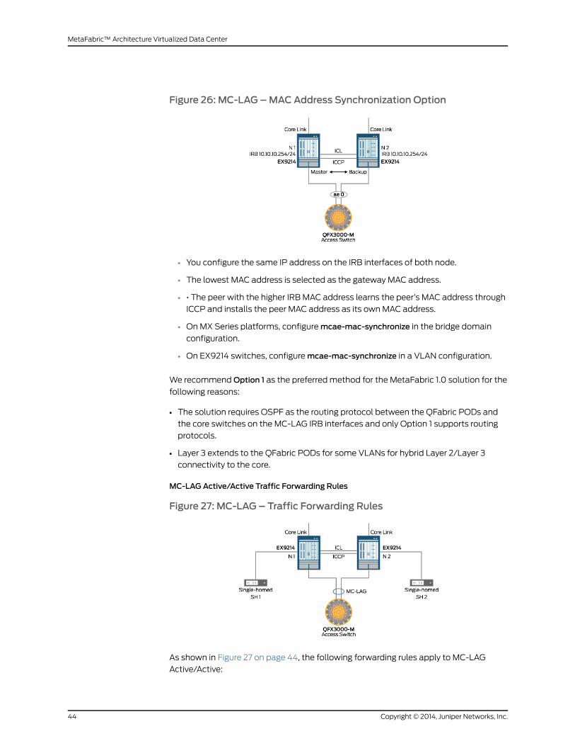
Figure 26: MC-LAG –MACAddress Synchronization Option
• You configure the same IP address on the IRB interfaces of both node.
• The lowest MAC address is selected as the gateway MAC address.
• • The peer with the higher IRB MAC address learns the peer’s MAC address through
ICCP and installs the peer MAC address as its ownMAC address.
• OnMX Series platforms, configuremcae-mac-synchronize in the bridge domain
configuration.
• On EX9214 switches, configuremcae-mac-synchronize in a VLAN configuration.
We recommendOption 1 as the preferred method for the MetaFabric 1.0 solution for the
following reasons:
• The solution requires OSPF as the routing protocol between the QFabric PODs and
the core switches on the MC-LAG IRB interfaces and only Option 1 supports routing
protocols.
• Layer 3 extends to the QFabric PODs for some VLANs for hybrid Layer 2/Layer 3
connectivity to the core.
MC-LAG Active/Active Traffic Forwarding Rules
Figure 27: MC-LAG – Traffic Forwarding Rules
As shown in Figure 27 on page 44, the following forwarding rules apply to MC-LAG
Active/Active:
Copyright © 2014, Juniper Networks, Inc.44
MetaFabric™ Architecture Virtualized Data Center

• Traffic received on N1 fromMCAE1 could be flooded to the ICL link to reach N2. When
it reaches N2, it must not be flooded back to MCAE1.
• Traffic received on SH1 could be flooded to MCAE1 and ICL by way of N1. When N2
receives SH1 traffic across the ICL link, it must not be again flooded to MCAE1. N2 also
receives the SH1 traffic by way of the MC-AE link.
• When receiving a packet from the ICL link, the MC-LAG peers forward the traffic to
all local SH links. If the corresponding MCAE link on the peer is down, the receiving
peer also forwards the traffic to its MCAE links.
NOTE: ICCP is used to signal MCAE link state between the peers.
• When N2 receives traffic from the ICL link and the N1 core link is up, the traffic should
not be forwarded to the N2 core link.
MC-LAG Active/Active High Availability Events
ICCP is down, when ICL is up:
Figure 28: MC-LAG – ICCP Down
Here are the actions that happen when the ICCP link is down and the ICL link is up:
• By default, if the ICCP link fails, as shown in Figure 28 on page 45, the peer defaults to
its own local LACP system ID and the links for only one peer (whichever one negotiates
with the customer edge [CE] router first) are attached to the bundle. Until LACP
converges with a new system ID, there will be minimum traffic impact.
• One peer stays active, while the other enters standbymode (but this is
nondeterministic).
• The access switch selects a core switch and establishes LACP peering.
To optimize for this condition, include the prefer-status-control-active statement on the
active peer.
• With the prefer-status-control-activestatement configured on the active peer, the peer
remains active and retains the same LACP system ID.
45Copyright © 2014, Juniper Networks, Inc.
Chapter 2: Design

• With the force-icl-down statement, the ICL link shuts down when the ICCP link fails.
• By configuring these statements, traffic impact isminimized during an ICCP link failure.
ICCP is up and ICL goes down:
Figure 29: MC-LAG – ICL Down
Here are the actions that happen when the ICCP link is up and the ICL link is down:
• If you configure a peer with the prefer-status-control-standby statement, the MC-AE
interfaces shared with the peer and connected to the ICL go down.
• This configuration ensures a loop-free topology because it does not forward duplicate
packets in the Layer 2 network.
Active MC-LAG node downwith ICCP loopback peering with prefer-status-control-active
on both peers:
Figure 30: MC-LAG – Peer Down
Here are the actions that happen when both MC-LAG peers are configured with the
prefer-status-control-active statement and the active peer goes down:
• When you configure MC-LAG Active/Active between SW1/SW2 and the QFabric POD,
SW1 becomes active and SW2 becomes standby. During an ICCP failure event, if SW1
has the prefer-status-control active statement and it fails, SW2 is not aware of the
Copyright © 2014, Juniper Networks, Inc.46
MetaFabric™ Architecture Virtualized Data Center

ICCP or SW1 failures. As a result, SW2mcae-id switches to the default LACP system
ID, which causes the MC-LAG link to go down and up, and results in long traffic
reconvergence times.
• To avoid this situation, configure the prefer-status-control-active statement on both
SW1andSW2.Also, youshouldprevent ICCP failuresbyconfiguring ICCPona loopback
interface.
• Configure backup-liveness-detection on both the active and standby peers. BFD helps
to detect peer failures and enable sub-second reconvergence.
The design for high availability in theMetaFabric 1.0 solutionmeets the requirements for
hardware redundancy and software redundancy.
Class of Service
Key design elements for class of service in this solution include network control (OSPF,
BGP, and BFD), virtualization control (high availability, fault tolerance), storage (iSCSI
andNAS), business-critical applications (Exchange,SharePoint,MediaWiki, andvMotion)
and best-effort traffic. As seen in Figure 31 on page 47, incoming packets are sorted,
assigned to queues based on traffic type, and transmitted based on the importance of
the traffic. For example, iSCSI lossless Ethernet traffic has the largest queue and highest
priority, followed by critical traffic (fault tolerance and high availability), business-critical
application traffic (including vMotion), andbulkbest-effort trafficwith the lowestpriority.
Figure 31: Class of Service – Classification and Queuing
As seen in Figure 32 on page 48, the following percentages are allocated for class of
service in this solution: network control (5 percent), virtualization control (5 percent),
storage (60 percent), business-critical applications (25 percent) and best-effort traffic
(5 percent). These categories have beenmaximized for network-level traffic, as the
network supportsmultiple serversandswitches.Asa result, storage traffic andapplication
traffic are the most critical traffic types in the network, and these allocations have been
verified by our testing.
47Copyright © 2014, Juniper Networks, Inc.
Chapter 2: Design

Figure 32: Class of Service – Buffer and Transmit Design
To provide class of service in the virtualized IT data center andmeet the design
requirements, this solution uses:
• Lossless Ethernet for storage traffic
• Five allocations to differentiate traffic
• A queue for business-critical applications
• Best-effort traffic for data traffic
Security
Security is a vital component of any network architecture and the virtualized IT data
center is no exception. There are various areas within the data center where security is
essential. At the perimeter, security is focused on securing the edge of the data center
fromexternal threatsandwithprovidinga securegateway to the Internet. Remoteaccess
is another area where security is vital in the data center. Operators will often require
remote access to the data center to performmaintenance or new service activations.
This remote accessmust be secured andmonitored to ensure that only authorized users
are permitted access. Robust authentication, authorization and accounting (AAA)
mechanisms should be in place to ensure that only authorized operators are allowed.
Given that the data center is a cost and revenue center that can house the critical data
andapplicationsofmanydifferententerprises,multi-factorauthentication isanabsolute
necessity to properly secure remote access.
Software application security in the virtualized IT data center is security that is provided
between VMs. A great deal of inter-VM communication occurs in the data center and
controlling this interactivity is a crucial security concern. If a server is supposed to access
a database residing on another server, or on a storage array, a virtual security appliance
should be configured to limit the communication between those resources to allow only
those protocols that are necessary for operation. Limiting the communication between
resources prevents security breaches in the data center andmight be a requirement
dependingon the regulatory requirementsof thehostedapplications (HIPPA, for instance,
Copyright © 2014, Juniper Networks, Inc.48
MetaFabric™ Architecture Virtualized Data Center

can dictate security safeguards that must exist between patient and business data). As
discussed in the VirtualMachine section, security in the virtual network, or betweenVMs,
differs fromsecurity that canbe implementedonaphysical network. Inaphysical network,
a hardware firewall can connect to different subnets, security zones, or servers and
provide security between those devices (Figure 33 on page 49). In the virtual network,
the physical firewall does not have the ability to see traffic between the VMs. In these
cases, a virtual hypervisor security appliance should be installed to enable security
between VMs.
Figure 33: Physical Security Compared to Virtual Network Security
Application Security
When securing VMs, you need a comprehensive virtualization security solution that
implements hypervisor security with full introspection; includes a high-performance,
hypervisor-based stateful firewall; uses an integrated intrusion detection system (IDS);
provides virtualization-specific antivirus protection; and offers unrivaled scalability for
managing multitenant cloud data center security. The Juniper Networks Firefly Host
(formerly vGW) offers all these features and enables the operator to monitor software,
patches, and files installed on a VM from a central location. Firefly Host is designed to
be centrally managed from a single-pane view, giving administrators a comprehensive
view of virtual network security and VM inventory.
Table 7 on page 50 shows the relativemerits of three application security design options:
vSRX,SRX,andFireflyHost.Becauseotherchoices lack intrusiondetectionandprevention,
quarantine capabilities, andmission-critical line-rate performance and scalability, Firefly
Host is the preferred choice for this solution. Additionally, Firefly Host is integrated into
all VMs and provides every endpoint with its own virtual firewall.
49Copyright © 2014, Juniper Networks, Inc.
Chapter 2: Design

Table 7: Application Security Options
Firefly HostSRXvSRXRequirement
YesYesYesStateful security policies
YesYesYesCentralizedmanagement
YesYesYesIntrusion detection and prevention
YesNoNoQuarantine
YesNoNo10G line-rate performance at scale
To provide application security in the virtualized IT data center, this solution uses the
Juniper Networks Firefly Host to provide VM-to-VM application security. Firefly Host
integrates with VMware vCenter for comprehensive VM security andmanagement.
Figure 34: Application Security Design
In Figure 34 on page 50, the following sequence occurs for VM-to-VM traffic:
1. A VM sends traffic to a destination VM.
2. The Firefly Host appliance inspects the traffic.
3. The traffic matches the security policy.
4. The ESXi host transmits the traffic.
5. The second ESXi host receives the traffic.
6. Firefly Host inspects the traffic.
7. The traffic matches the security policy and permits the traffic to continue to the
destination.
8. The destination VM receives the traffic.
Copyright © 2014, Juniper Networks, Inc.50
MetaFabric™ Architecture Virtualized Data Center
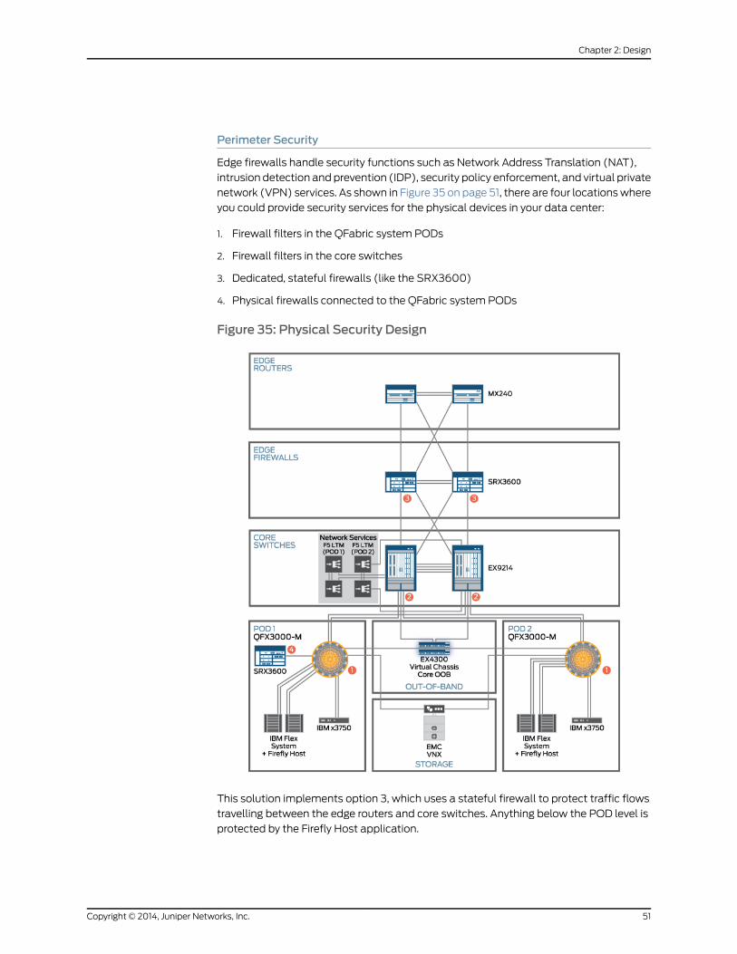
Perimeter Security
Edge firewalls handle security functions such as Network Address Translation (NAT),
intrusion detection and prevention (IDP), security policy enforcement, and virtual private
network (VPN) services. As shown in Figure 35 on page 51, there are four locationswhere
you could provide security services for the physical devices in your data center:
1. Firewall filters in the QFabric system PODs
2. Firewall filters in the core switches
3. Dedicated, stateful firewalls (like the SRX3600)
4. Physical firewalls connected to the QFabric system PODs
Figure 35: Physical Security Design
This solution implements option 3, which uses a stateful firewall to protect traffic flows
travelling between the edge routers and core switches. Anything below the POD level is
protected by the Firefly Host application.
51Copyright © 2014, Juniper Networks, Inc.
Chapter 2: Design
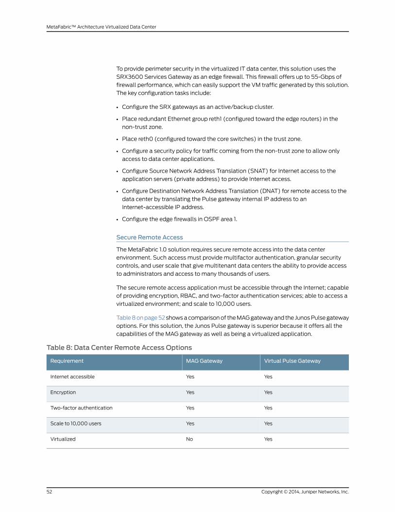
To provide perimeter security in the virtualized IT data center, this solution uses the
SRX3600 Services Gateway as an edge firewall. This firewall offers up to 55-Gbps of
firewall performance, which can easily support the VM traffic generated by this solution.
The key configuration tasks include:
• Configure the SRX gateways as an active/backup cluster.
• Place redundant Ethernet group reth1 (configured toward the edge routers) in the
non-trust zone.
• Place reth0 (configured toward the core switches) in the trust zone.
• Configure a security policy for traffic coming from the non-trust zone to allow only
access to data center applications.
• Configure Source Network Address Translation (SNAT) for Internet access to the
application servers (private address) to provide Internet access.
• Configure Destination Network Address Translation (DNAT) for remote access to the
data center by translating the Pulse gateway internal IP address to an
Internet-accessible IP address.
• Configure the edge firewalls in OSPF area 1.
Secure Remote Access
The MetaFabric 1.0 solution requires secure remote access into the data center
environment. Such access must provide multifactor authentication, granular security
controls, and user scale that give multitenant data centers the ability to provide access
to administrators and access to many thousands of users.
The secure remote access application must be accessible through the Internet; capable
of providing encryption, RBAC, and two-factor authentication services; able to access a
virtualized environment; and scale to 10,000 users.
Table8onpage52showsacomparisonof theMAGgatewayand the JunosPulsegateway
options. For this solution, the Junos Pulse gateway is superior because it offers all the
capabilities of the MAG gateway as well as being a virtualized application.
Table 8: Data Center Remote Access Options
Virtual Pulse GatewayMAGGatewayRequirement
YesYesInternet accessible
YesYesEncryption
YesYesTwo-factor authentication
YesYesScale to 10,000 users
YesNoVirtualized
Copyright © 2014, Juniper Networks, Inc.52
MetaFabric™ Architecture Virtualized Data Center
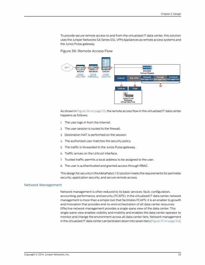
To provide secure remote access to and from the virtualized IT data center, this solution
uses the Juniper Networks SASeries SSLVPNAppliances as remote access systems and
the Junos Pulse gateway.
Figure 36: Remote Access Flow
As shown in Figure 36onpage53, the remote access flow in the virtualized IT data center
happens as follows:
1. The user logs in from the Internet.
2. The user session is routed to the firewall.
3. Destination NAT is performed on the session.
4. The authorized user matches the security policy.
5. The traffic is forwarded to the Junos Pulse gateway.
6. Traffic arrives on the Untrust interface.
7. Trusted traffic permits a local address to be assigned to the user.
8. The user is authenticated and granted access through RBAC.
Thisdesign for security in theMetaFabric 1.0 solutionmeets the requirements forperimeter
security, application security, and secure remote access.
NetworkManagement
Network management is often reduced to its basic services: fault, configuration,
accounting, performance, and security (FCAPS). In the virtualized ITdata center, network
management ismore than a simple tool that facilitates FCAPS: it is an enabler to growth
and innovation that provides end-to-end orchestration of all data center resources.
Effective network management provides a single-pane view of the data center. This
single-pane view enables visibility andmobility and enables the data center operator to
monitor and change the environment across all data center tiers. Networkmanagement
in thevirtualized ITdatacenter canbebrokendown into seven tiers (Figure37onpage54).
53Copyright © 2014, Juniper Networks, Inc.
Chapter 2: Design
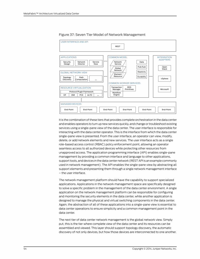
Figure 37: Seven Tier Model of Network Management
It is the combinationof these tiers thatprovides completeorchestration in thedata center
andenablesoperators to turnupnewservicesquickly, andchangeor troubleshootexisting
services using a single-pane view of the data center. The user interface is responsible for
interactingwith the data center operator. This is the interface fromwhich the data center
single-pane view is presented. From the user interface, an operator can view, modify,
delete, or add network elements and new services. The user interface acts as a single
role-based access control (RBAC) policy enforcement point, allowing an operator
seamless access to all authorized devices while protecting other resources from
unapproved access. The application programming interface (API) enables single-pane
management by providing a common interface and language to other applications,
support tools, anddevices in thedatacenternetwork (RESTAPI isanexamplecommonly
used in network management). The API enables the single-pane view by abstracting all
support elements and presenting them through a single networkmanagement interface
– the user interface.
The network management platform should have the capability to support specialized
applications. Applications in the network management space are specifically designed
to solve a specific problem in themanagement of the data center environment. A single
application on the network management platform can be responsible for configuring
andmonitoring the security elements in the data center, while another application is
designed to manage the physical and virtual switching components in the data center.
Again, the abstraction of all of these applications into a single-pane view is essential to
data center operations to ensure simplicity and a commonmanagement point in the
data center.
The next tier of data center network management is the global network view. Simply
put, this is the tier where complete view of the data center and its resources can be
assembled and viewed. This layer should support topology discovery, the automatic
discovery of not only devices, but how those devices are interconnected to one another.
Copyright © 2014, Juniper Networks, Inc.54
MetaFabric™ Architecture Virtualized Data Center
Theglobalnetworkviewshouldalsosupportpathcomputation(the linkdistancebetween
network elements as well as the set of established paths between those network
elements). The resourcevirtualization tier ofnetworkmanagementenablesmanagement
of the various endpoints in the data center and acts as an abstraction layer that allows
the operator to manage endpoints that require different protocols such as OpenFlow or
Device Management Interface (DMI).
Thecommondataservices tierofnetworkmanagementenables thevariousapplications
and interfaceson thenetworkmanagementsystemtoshare relevant informationbetween
the layers.Anapplication thatmanagesasetof endpointsmight requirenetwork topology
details in order to map and potentially push changes to those network devices. This
requires that the applications within the network management system share data; this
is enabled by the common data services layer.
Managed devices in the network management role are simply the endpoints that are
managedby thenetworkmanagement system.Thesedevices includephysical andvirtual
switches, routers, VMs, blade servers, and security appliances, to name a few. The
managed devices and the orchestration of services between those devices is the prime
purpose of the network management system. Network management should be the
answer to the question, ”how does a data center operator easily stand up andmaintain
services within the data center?” The network management system orchestrates the
implementation and operation of the managed devices in the data center
Finally, integrationadaptersare requiredwithinacompletenetworkmanagement system.
As every device in the data center might not bemanageable by a single network
management system, other appliances or services might be required to manage the
entiredatacenter.The integrationandcoordinationof thesevariousnetworkmanagement
tools is the purpose of this layer. Some data center elements such as Virtual Machines
might require VMware ESXi server to manage the VMs and hypervisor switch, while
another network management appliancemonitors environmental and performance
conditions on the host server. A third systemmight be responsible for configuring and
monitoring the network connections between the blade servers and the rest of the data
center. Integration adapters enable each of these components to talk to one another
and, in many cases, allow a single network management system to control the entire
network management footprint from a single pane of glass.
Out-of-BandManagement
The requirements for out-of-bandmanagement include:
• Administration of the compute, network, and storage segments of the data center.
• Separation of the control plane from the data plane so themanagement network
remains accessible.
• Support for 1-Gigabit Ethernet management interfaces.
• Provide traffic separation across compute, network, and storage segments.
• Enable administrators access to the management network.
• Denymanagement-to-management traffic.
Some of the key elements of this design are seen in Figure 38 on page 56.
55Copyright © 2014, Juniper Networks, Inc.
Chapter 2: Design

Figure 38: Out of BandManagement Network Design
To provide out-of-bandmanagement in the virtualized IT data center, this solution uses
two pairs of EX4300 switches configured as a Virtual Chassis (Figure 39 on page 57).
The key connection and configuration steps include:
• • Connect all OOB network devices to the EX4300 Virtual Chassis (100-Megabit Fast
Ethernet and 1-Gigabit Ethernet).
• Configure the EX4300 Virtual Chassis OOBmanagement system in OSPF area 2.
• Connect the 2 IBM 3750 standalone servers that host themanagement VMs (vCenter,
Junos Space, Network Director 1.5, domain controller, and Junos Pulse gateway) to the
EX4300 Virtual Chassis.
• • Create four VLANs to separate storage, compute, network, andmanagement traffic
from each other.
• Manage andmonitor the VMs on the test bed using VMware vSphere and Network
Director 1.5.
Copyright © 2014, Juniper Networks, Inc.56
MetaFabric™ Architecture Virtualized Data Center

Figure 39: Out of BandManagement – Detail
Network Director
To provide network configuration and provisioning in the virtualized IT data center, this
solution uses Juniper Networks Network Director. Network Director 1.5 is used tomanage
network configuration, provisioning, andmonitoring
Security Director
Toprovide security policy configuration in the virtualized IT data center, this solution uses
Juniper Networks Security Director. Security Director is used to manage security policy
configuration and provisioning.
This designmeets the networkmanagement requirements ofmanaging both virtual and
physical components within the data center and handling the FCAPS considerations.
Performance and Scale
• The solution must support 20,000 virtual machines and scale up to 2,000 servers.
• The solution must support a total of 30,000 users.
• 10,000Microsoft Exchange users
• 10,000Microsoft SharePoint user transactions
• 10,000MediaWiki user transactions
• The solutionmust offer less than 3μ latency between servers and 21μ latency between
PODs
• The solution must provide high availability.
• Less than one second convergence*
• No single point of failure
57Copyright © 2014, Juniper Networks, Inc.
Chapter 2: Design

Summary of Key Design Elements
To recap the key components of the design for this solution, see Table 9 on page 58.
Table 9: Summary of Key Design Elements – Virtualized IT Data Center Solution
SoftwareHardware PlatformRole
13.2R1.7MX480Edge Router
12.1X44-D30.4SRX3600Edge Firewall
13.2R3.2EX9214Core Switch
13.1X50-D15QFX3000-MPOD 1
13.1X50-D15QFX3000-MPOD 2
13.2X50-D10EX4300-VCOOBManagement
7.4R1.0vSecure AccessRemote Access
1.5Network DirectorNetworkManagement
7.1.56-5EMC VNX 5500Storage
2PET10KIBM Flex SystemCompute
10.2.5 Build 591.0F5 VIPRION 4480Load Balancer
5.1VMware vSphereVirtualization
5.5Firefly HostApplication Security
Benefits
There are several benefits to the virtualized IT data center described in this guide:
• Agility—The solution enables rapid deployment of new VMs and services.
• VMmotion—Virtual machines can bemoved and redeployed quickly anywhere in the
data center.
• Visibility of physical and virtual elements—The solution offers insight for the
administrator into theentire compute, network, andstoragesystemforboth thephysical
components and the virtual machines and switches.
• Simplifiedmanagement—The solution implements several components, such as the
QFabric system, Network Director, vCenter, and Firefly Host, that provide single points
ofmanagement that reduce thenumber of logins that are required for anadministrator
to monitor andmaintain the data center.
Copyright © 2014, Juniper Networks, Inc.58
MetaFabric™ Architecture Virtualized Data Center
• Systemuptime—Highavailability features, suchasMC-LAG,nonstopsoftwareupgrades,
in-service software upgrades, VRRP, and hardware redundancy, are included in the
solution to keep your data center up and running.
• Customer confidence—Through the efforts of the Juniper Networks Solution Validation
team, the validated solution in this guide can provide quicker understanding, adoption,
and implementation of the solution itself to provide your virtualized IT data centerwith
a competitive edge.
59Copyright © 2014, Juniper Networks, Inc.
Chapter 2: Design

Copyright © 2014, Juniper Networks, Inc.60
MetaFabric™ Architecture Virtualized Data Center

CHAPTER 3
MetaFabric 1.0 High Level Testing andValidation Overview
The following section provides a high-level overview of the MetaFabric 1.0 solution.
Specific implementation details for each operational role begin in Chapter 4.
• Overview on page 61
• Key Characteristics of Implementation on page 62
Overview
Topology
This solution document focuses on a deployment scenario that provides a
performance-oriented fabricwith 3:1 over-subscription, supporting up to 768x10-Gigabit
portsand thedeploymentofup to7PODs.Thesolution features low-latencydeterministic
traffic forwarding using the Juniper Networks QFX3000-MQFabric System in the access
and aggregation roles (at the POD level). The end-to-end lab testing topology is shown
in Figure 40 on page 62.
61Copyright © 2014, Juniper Networks, Inc.

Figure 40: The End to End Lab Topology
Key Characteristics of Implementation
The MetaFabric 1.0 solution was verified in the Juniper Networks solution validation labs
using the following set of design elements and features:
• Transport: MC-LAG Active/Active with VRRP and SRX JSRP, IRB and VLAN, Lossless
Ethernet
• Protocols: OSPF, BGP
• High availability: NSSU, ISSU, SRX Cluster
• Security: Perimeter - SRX3600, App Security - Firefly Host
• Remote access: SA network and VM appliance configuration
Copyright © 2014, Juniper Networks, Inc.62
MetaFabric™ Architecture Virtualized Data Center

• OOB: EX4300-VC
• Compute and virtualization: IBM Flex chassis, VMware 5.1, vCenter
• Network management: Juno Space, Network Director 1.5
• Application load balancer: F5 DSR LB implementation
• Quality of service: Lossless Ethernet, PFC, DCBX
• Scale and performance: SharePoint, Exchange, Wikimedia scale with Shenick Tester
• POD1 and POD2 are configured with the QFX3000-MQFabric system as an access
and aggregation switch.
POD1 (QFX3000-MQFabric) Configuration
ThePOD1 JuniperNetworks®QFX3000-MQFabricSystem isconfiguredwith the following
elements:
• Three redundant server node groups (RSNG) connected to two IBM Flex blade servers
• IBMFlex-1 has 40-Gigabit CNA connected to anRSNGwithQFX3600nodes (RSNG4)
• IBM-Flex-2 has 10-Gigabit pass-thru modules connected to RSNG2 and RSNG3
• EMC VNX storage is connected to the QFabric for storage access though iSCSI and
NFS
• QFX3000-MQFabric system is also configured with one network node group (NNG)
with two nodes connected to EX9214 core-switch using 4 X 24port link aggregation
groups (LAGs) configured as trunk ports
• POD1 (QFabric NNG toward EX9214): Area10 (totally stubby area)
POD2 (QFX3000-MQFabric) Configuration
The Juniper Networks®QFX3000-MQFabric System deployed in POD2 is configured
with the following elements:
• Three RSNG connected to two IBM Flex blade servers
• IBM IBM-Flex-2 has 10-Gigabit pass-thru modules connected to RSNG2 and RSNG3
• EMC VNX storage is connected to the QFabric for storage access though iSCSI and
NFS
• QFX3000-MQFabric system is also configured with one NNG node-group with two
nodes connected to EX9214 core-switch using 4 X 32 port LAGs configured as trunk
ports
• POD2 (QFabric NNG toward EX9214): Area11 (totally stubby area)
63Copyright © 2014, Juniper Networks, Inc.
Chapter 3: MetaFabric 1.0 High Level Testing and Validation Overview

Core Switch (EX9214) Implementation
The core role deployed in the solution verification lab features the Juniper Networks®
EX9214 Ethernet Switch with the following configuration elements:
• Layer 2 MC-LAG Active/Active is configured on EX9214 toward QFabric-m, F5 LB,
MX240 toward SRX3600
• IRB is configured on EX9214 and QFabric and QFX-VC to terminate the Layer 2/Layer
3 boundary
• Static route is configured to core-switch the traffic to load balancer (LB) from Internet
• OSPF is configured to send only default routes to the NSSA areas toward POD1 and
POD2
• IRB and VRRP are configured for all MC-LAG links
• Core-switch is configured as ABR having all three areas connected
• OSPF area 0 is ae20 between the two core-switches
Edge Firewall (SRX3600) Implementation
The edge firewall role was tested and verified featuring the Juniper Networks®SRX3400
Services Gateway. The edge firewall implementation was configured with the following
elements:
• SRX Active/Backup cluster configured
• reth1 configured toward edge routers in untrust zone
• reth0 configured toward core-switch in trust zone
• Security policy is configured for traffic from untrust zone to allow only access to DC
applications
• S-NAT is configured for Internet access to application servers (private address) to
provide Internet access
• D-NAT is configured for remote access to the data center for Pulse gateway internal
IP address to Internet accessible IP address
• Firewall is configured in OSPF area 1
Edge routers (MX240) Implementation
Theedge routing role in theMetaFabric 1.0 solution features the JuniperNetworks®MX240
3DUniversal Edge Router. The edge routing was configuredwith the following elements:
• MX240 pair configured as edge routers connected to service provider network for DC
Internet access
• Both the edge-r1 and edge-r2 EBGP peering with SP1 and SP2
• IBGP is configured between edge-r1 and edge-r2 with next-hop self export policy
Copyright © 2014, Juniper Networks, Inc.64
MetaFabric™ Architecture Virtualized Data Center
• Local-preference is configured on SP1 as a preferred exit point to Internet
• Conditionbased(basedon Internet route)default route injection intoOSPF isconfigured
on both the edge-r1 and edge-r2 toward the firewall/core-switches for Internet access
to VDC devices
• Edge routers (two MX240s): Area1
Compute (IBM Flex chassis) Implementation
The computing role in the solution test labswas built using compute hardware from IBM,
including the IBMFlex Chassis. This role in the solutionwas configuredwith the following
elements:
• o IBM Flex server is configured with multiple ESXi hosts hosting all the VMs running
the business-critical applications (SharePoint, Exchange, Media-wiki, andWWW)
• o Distributed vSwitch is configured betweenmultiple physical ESXi hosts configured
in IBM hosts
OOB-Mgmt (EX4300-VC) Implementation
The entire solution ismanagedout-of-band (OOB) featuring JuniperNetworks®EX4200
Ethernet Switches with Virtual Chassis technology. The OOBmanagement role was
configured and tested with the following elements:
• All the network device OOB connections are plugged into the EX4200-VC (100mand
1 Gbps)
• OOB-MGMT (EX4300-vc): OSPF Area 0
• Two X IBM 3750 standalone servers are connected to the EX4300-VC hosting all the
managementVMs(vCenter, JunosSpace,ND1.5, domaincontroller, andPulsegateway)
• VMware vSphere/Network Director 1.5 used to orchestrate the VMs on the test bed
• Network Director 1.5 is used to configure or orchestrate network configuration and
provisioning
• JuniperNetworksVGWgateway is configuredonaVMtoprovideVM-to-VMapplication
security
65Copyright © 2014, Juniper Networks, Inc.
Chapter 3: MetaFabric 1.0 High Level Testing and Validation Overview
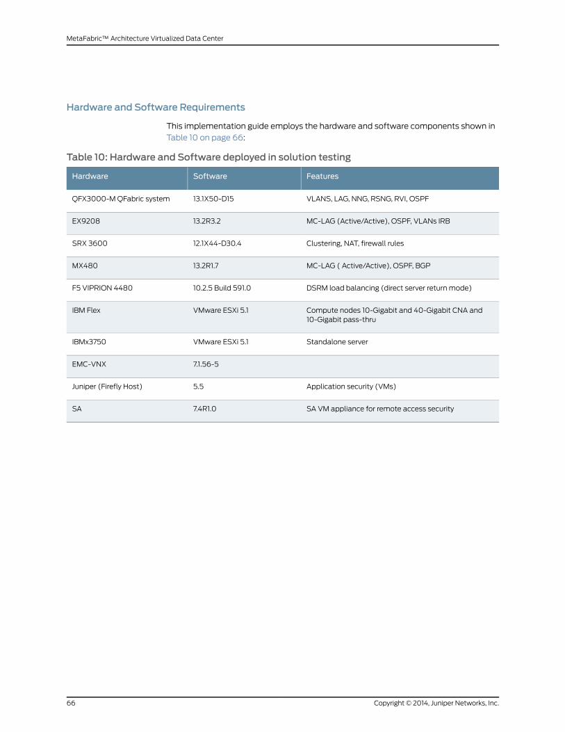
Hardware and Software Requirements
This implementation guide employs the hardware and software components shown in
Table 10 on page 66:
Table 10: Hardware and Software deployed in solution testing
FeaturesSoftwareHardware
VLANS, LAG, NNG, RSNG, RVI, OSPF13.1X50-D15QFX3000-MQFabric system
MC-LAG (Active/Active), OSPF, VLANs IRB13.2R3.2EX9208
Clustering, NAT, firewall rules12.1X44-D30.4SRX 3600
MC-LAG ( Active/Active), OSPF, BGP13.2R1.7MX480
DSRM load balancing (direct server return mode)10.2.5 Build 591.0F5 VIPRION 4480
Compute nodes 10-Gigabit and 40-Gigabit CNA and10-Gigabit pass-thru
VMware ESXi 5.1IBM Flex
Standalone serverVMware ESXi 5.1IBMx3750
7.1.56-5EMC-VNX
Application security (VMs)5.5Juniper (Firefly Host)
SA VM appliance for remote access security7.4R1.0SA
Copyright © 2014, Juniper Networks, Inc.66
MetaFabric™ Architecture Virtualized Data Center

In addition, Table 11 on page 67 provides an overview of the network management and
provisioning tools used to validate the solution.
Table 11: Software deployed in MetaFabric 1.0 test bed
FeaturesVersionHardware installedApplication
Virtual-view (VMprovisioning/monitoring)
1.5VMsNetwork Director
Provisioning andmonitoring SRX3600
13.1R1VMsSecurity Director
13.1 R1VMsJunos space
5.1VMsVmware vCenter
Not supportedVMsSecurity Design
13.1 R1VMsService Now
The solution is configured with IP addressing as shown in Table 12 on page 67:
Table 12: Networks and VLANs Deployed in the Test Lab
Vlan-NameVLAN-IDGatewayNetworkNetwork Subnets
Network VLAN80410.94.47.3010.94.47.0/27Network Devices
Security-VLAN80110.94.47.6210.94.47.32/27Security Devices
Storage-VLAN80310.94.47.7810.94.47.64/28Unused
compute-vlan80010.94.47.9410.94.47.80/28Storage Devices
compute-VLAN80010.94.47.12610.94.47.96/27IBMCompute nodeConsoleIP
compute-VLAN80010.94.47.25410.94.47.128/25ESX Compute NodeManagement IP
10.94.63.25410.94.63.0/24VMs
Internet Routable Subnets
10.94.127.3010.94.127.0/27VDC App Server Internet IP(source NAT pool)
10.94.127.6210.94.127.32/27SA IP address
67Copyright © 2014, Juniper Networks, Inc.
Chapter 3: MetaFabric 1.0 High Level Testing and Validation Overview

Table 12: Networks and VLANs Deployed in the Test Lab (continued)
Vlan-NameVLAN-IDGatewayNetworkNetwork Subnets
Unrestricted address space fortester ports connected inside theVDC. No security policy for theaddress space.
10.94.127.12610.94.127.64/26Unused
Publicly available applications inVDC.
10.94.127.19010.94.127.128/26Server VIP address
Address space for VMs on theexternal network for simulation ofclient traffic
10.94.127.22210.94.127.192/27LAN client VM and TrafficGenerator address
Address space further subdividedfor point-to-point links inside SP1cloud. No gateway.
10.94.127.224/28SP1 address
Address space further subdividedfor point-to-point links inside SP2cloud. No gateway.
0.94.127.240/28SP2 address
Applications tested as part of the solution were configured with address space shown
in Table 13 on page 68:
Table 13: Applications Tested in theMetaFabric 1.0 Solution
GatewayVlan-IDInternal addressExternal addressApplication
OOB-MGMT81010.94.63.2410.94.127.33SA
POD1-SW1104172.16.4.10 -1210.94.127.181Exchange
POD2-SW1102172.16.2.11 -1410.94.127.180SP
POD1-SW1103172.16.3.1110.94.127.182WM
Multi-chassis LAG is used in the solution between core and aggregation or access to
enable always-up, loop-free, and load-balanced traffic between the switching roles in
the data center (Figure 41 on page 69).
Copyright © 2014, Juniper Networks, Inc.68
MetaFabric™ Architecture Virtualized Data Center

Figure 41: MC-LAG Active/Active Logical Topology
69Copyright © 2014, Juniper Networks, Inc.
Chapter 3: MetaFabric 1.0 High Level Testing and Validation Overview
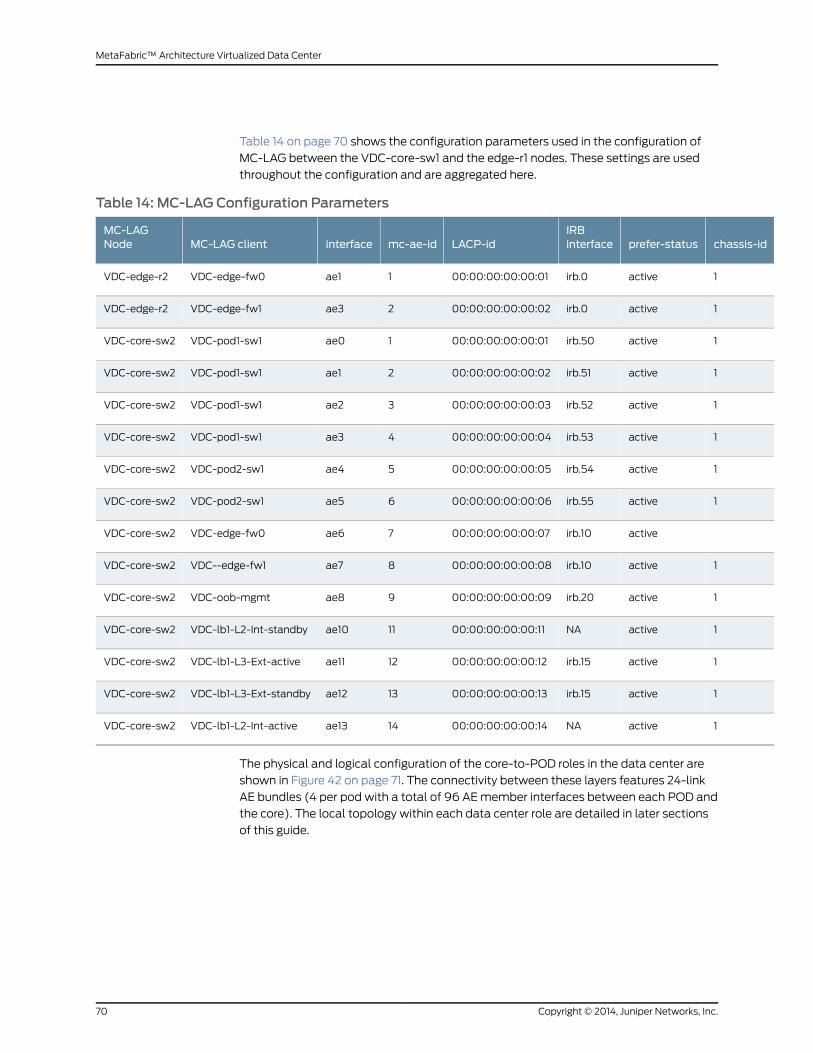
Table 14 on page 70 shows the configuration parameters used in the configuration of
MC-LAG between the VDC-core-sw1 and the edge-r1 nodes. These settings are used
throughout the configuration and are aggregated here.
Table 14: MC-LAG Configuration Parameters
chassis-idprefer-statusIRBinterfaceLACP-idmc-ae-idinterfaceMC-LAG client
MC-LAGNode
1activeirb.000:00:00:00:00:011ae1VDC-edge-fw0VDC-edge-r2
1activeirb.000:00:00:00:00:022ae3VDC-edge-fw1VDC-edge-r2
1activeirb.5000:00:00:00:00:011ae0VDC-pod1-sw1VDC-core-sw2
1activeirb.5100:00:00:00:00:022ae1VDC-pod1-sw1VDC-core-sw2
1activeirb.5200:00:00:00:00:033ae2VDC-pod1-sw1VDC-core-sw2
1activeirb.5300:00:00:00:00:044ae3VDC-pod1-sw1VDC-core-sw2
1activeirb.5400:00:00:00:00:055ae4VDC-pod2-sw1VDC-core-sw2
1activeirb.5500:00:00:00:00:066ae5VDC-pod2-sw1VDC-core-sw2
activeirb.1000:00:00:00:00:077ae6VDC-edge-fw0VDC-core-sw2
1activeirb.1000:00:00:00:00:088ae7VDC--edge-fw1VDC-core-sw2
1activeirb.2000:00:00:00:00:099ae8VDC-oob-mgmtVDC-core-sw2
1activeNA00:00:00:00:00:1111ae10VDC-lb1-L2-Int-standbyVDC-core-sw2
1activeirb.1500:00:00:00:00:1212ae11VDC-lb1-L3-Ext-activeVDC-core-sw2
1activeirb.1500:00:00:00:00:1313ae12VDC-lb1-L3-Ext-standbyVDC-core-sw2
1activeNA00:00:00:00:00:1414ae13VDC-lb1-L2-Int-activeVDC-core-sw2
The physical and logical configuration of the core-to-POD roles in the data center are
shown in Figure 42 on page 71. The connectivity between these layers features 24-link
AE bundles (4 per pod with a total of 96 AEmember interfaces between each POD and
the core). The local topology within each data center role are detailed in later sections
of this guide.
Copyright © 2014, Juniper Networks, Inc.70
MetaFabric™ Architecture Virtualized Data Center

Figure 42: Topology of Core-to-POD Roles in the Data Center
71Copyright © 2014, Juniper Networks, Inc.
Chapter 3: MetaFabric 1.0 High Level Testing and Validation Overview

The configuration of integrated routing and bridging (IRB) interfaceswithin this segment
of the data center is outlined in Table 15 on page 72.
Table 15: IRB, IP Address Mapping
DescriptionVRRP IPTransportVLANIP address
ClientInterfaceMC-LAG clientIP address
IRBinterface
Untrust-Edge-fw192.168.26.25411192.168.26.3reth1VDC-edge-fw0192.168.26.1irb.0
Untrust-Edge-fw11192.168.26.3reth1VDC-edge-fw1192.168.26.1irb.0
POD1-uplink-1192.168.50.25450192.168.50.3nw-ng-0:ae0VDC-pod1-sw1192.168.50.1irb.50
POD1-uplink-1192.168.51.25451192.168.51.3nw-ng-0:ae1VDC-pod1-sw1192.168.51.1irb.51
POD1-uplink-3192.168.52.25452192.168.52.3nw-ng-0:ae2VDC-pod1-sw1192.168.52.1irb.52
POD1-uplink-4192.168.53.25453192.168.53.3nw-ng-0:ae3VDC-pod1-sw1192.168.53.1irb.53
POD2-uplink-1192.168.54.25454192.168.54.3ae0VDC-pod2-sw1192.168.54.1irb.54
POD2-uplink-2192.168.55.25455192.168.55.3ae1VDC-pod2-sw1192.168.55.1irb.55
Trust-Edge-fw192.168.25.25410192.168.25.3reth0VDC-edge-fw0192.168.25.1irb.10
Trust-Edge-fw192.168.25.25410192.168.25.3reth0VDC--edge-fw1192.168.25.1irb.10
OOB-MGMT-sw192.168.20.25420192.168.20.3ae0VDC-oob-mgmt192.168.20.1irb.20
Layer-2-server-facingcore-swVDC-lb1-L2-Int-standbyNA
layer3-External-link192.168.15.25415192.168.15.5ExternalVDC-lb1-L3-Ext-active192.168.15.1irb.15
Layer3-External-link192.168.15.25415192.168.15.5ExternalVDC-lb1-L3-Ext-standby192.168.15.1irb.15
Layer-2-server-facingcore-swVDC-lb1-L2-Int-activeNA
Copyright © 2014, Juniper Networks, Inc.72
MetaFabric™ Architecture Virtualized Data Center

CHAPTER 4
Transport (Routing and Switching)Configuration
This section covers the configuration of all network elements between the edge and the
data center Point of Delivery (POD) The section includes the following configuration and
verification areas:
• Network configuration
• Configuring edge, perimeter, and core
• Configuring core to PODs
• Routing protocol configuration
• Network Configuration on page 73
• Verification on page 81
• Implementing MC-LAG Active/Active with VRRP on page 85
• Configuring the Network Between the Data Center Core and the Data Center
PODs on page 86
• Verification on page 95
• Routing Configuration on page 104
Network Configuration
Overview
Configuration of the solution starts with the configuration of the perimeter security;
integration between the edge, perimeter and the data center core; and then continues
with configuration of the access and aggregation roles in the data center (in this solution,
those roles are collapsed into theQFabric POD). Finally, the networkmust be configured
in the virtual switching role.
Configuring the Network Between the Data Center Edge and the Data Center Core
This configuration includeselementsofhighavailability as theconfigurationandoperation
of the solution are heavily reliant on the use of Juniper Networks Virtual Chassis and
employmulti-chassis link aggregation (MC-LAG) between each data center operational
role.
73Copyright © 2014, Juniper Networks, Inc.

SRX chassis clustering provides high availability and redundancy by grouping two SRX
Series services gateways (must be the samemodel) into a cluster. The cluster consists
of a primary node and a secondary node. These nodes provide backup for each other in
the event of software, hardware, or network failures. Session state is synchronized
between thenodes in theSRXcluster to ensure that established sessionsaremaintained
during failover and reversion. The two nodes synchronize configuration, processes, and
services utilizing two Ethernet links: a control link is established to enable control plane
synchronization and a fabric link is established to enable data plane communication
(traversal of network traffic between cluster nodes).
Redundant Ethernet Trunk Group LAGs (RETH interfaces) can be established across
nodes in a chassis cluster (Figure 43 on page 74). Link aggregation allows a redundant
Ethernet interface (knownas aRETH interface in theCLI) to addmultiple child interfaces
frombothnodesof anSRXcluster, creatinga single, virtual interfaceoverwhichupstream
and downstream devices can communicate. This solution features active/standby SRX
cluster configuration: all active links are located on one SRX, and all standby links are on
the other SRX. In an SRX active/backup cluster, LAGmember links from the active node
will forward data traffic. Link Aggregation Control Protocol (LACP) is enabled on the
redundantEthernet interfacesimilar toanyaggregatedEthernet (AE) interfaceconfigured
in other routers/ or switches. The SRXRETH interface configuration includes allmember
interfaces from both the active and backup node.
Figure 43: Configuration of RETH Interfaces andMC-LAG Between Coreand Perimeter (Right) Compared to Configuration of RETH Interfacesand AE (Left)
Topology
The topology used in this section of the configuration is shown in Figure 44 on page 75.
Copyright © 2014, Juniper Networks, Inc.74
MetaFabric™ Architecture Virtualized Data Center
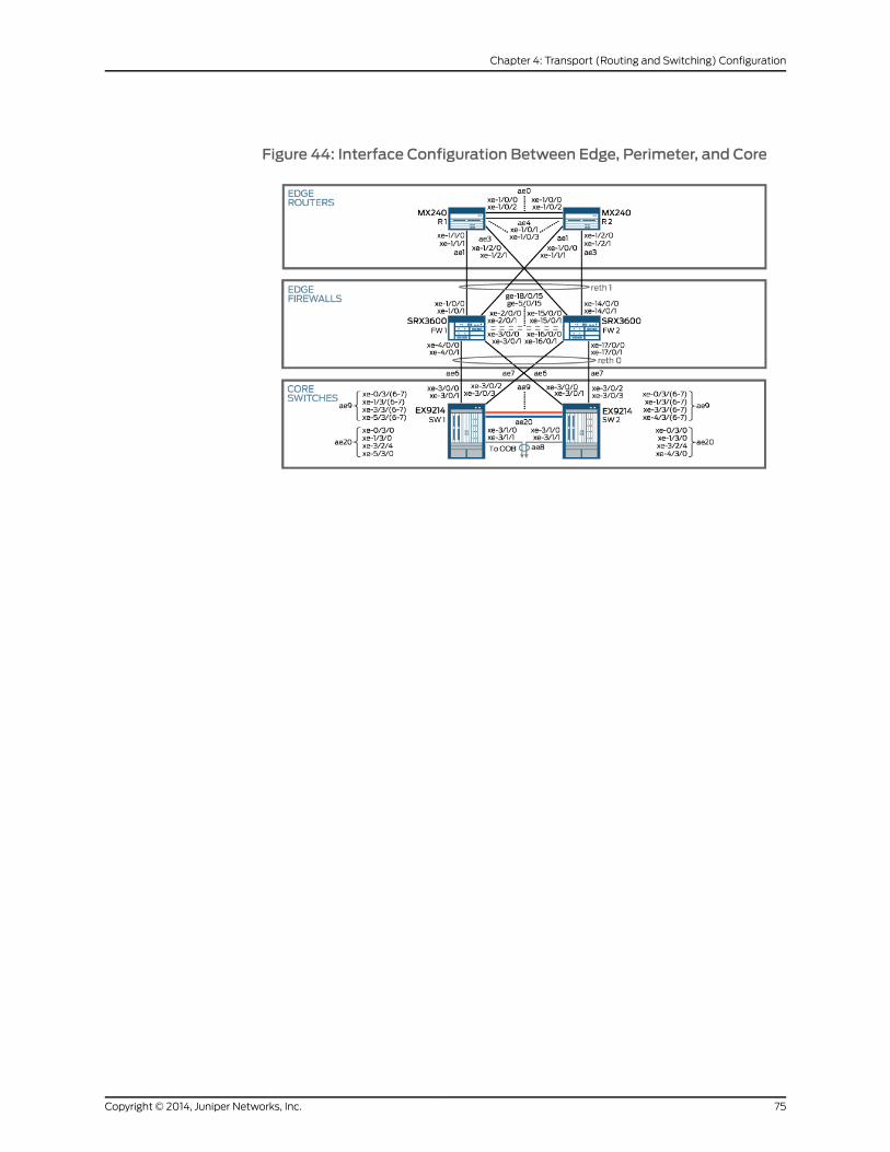
Figure 44: Interface Configuration Between Edge, Perimeter, and Core
75Copyright © 2014, Juniper Networks, Inc.
Chapter 4: Transport (Routing and Switching) Configuration
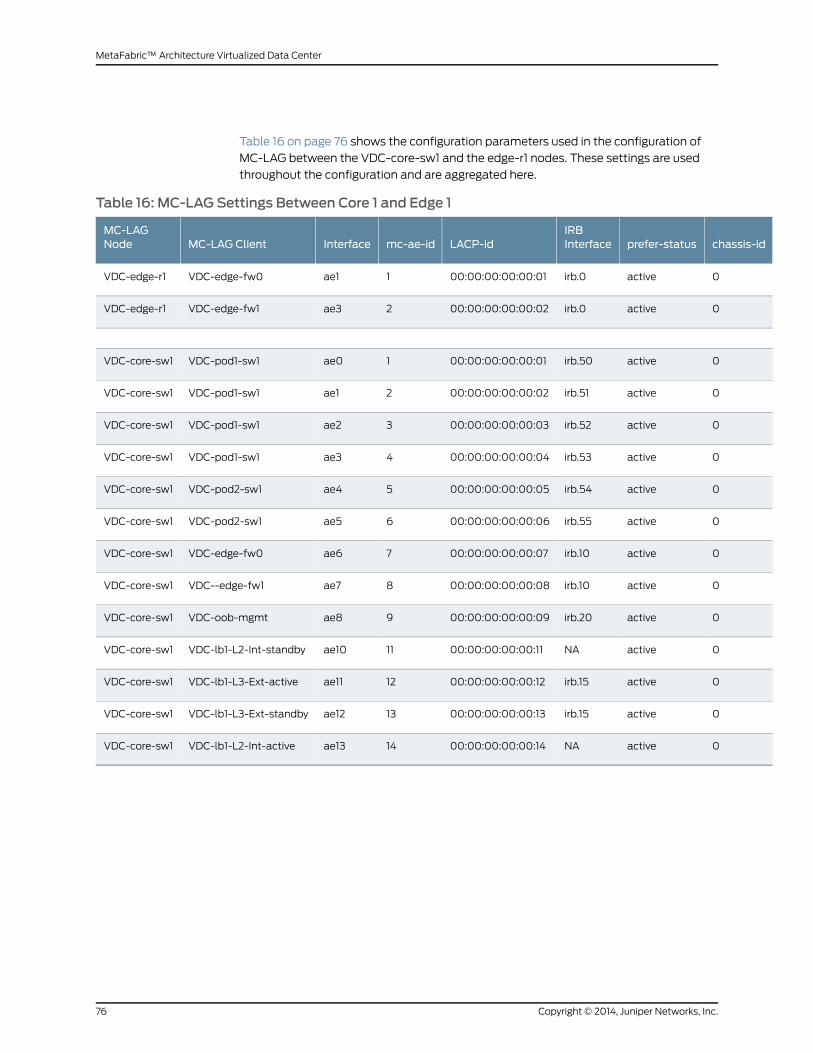
Table 16 on page 76 shows the configuration parameters used in the configuration of
MC-LAG between the VDC-core-sw1 and the edge-r1 nodes. These settings are used
throughout the configuration and are aggregated here.
Table 16: MC-LAG Settings Between Core 1 and Edge 1
chassis-idprefer-statusIRBInterfaceLACP-idmc-ae-idInterfaceMC-LAG Client
MC-LAGNode
0activeirb.000:00:00:00:00:011ae1VDC-edge-fw0VDC-edge-r1
0activeirb.000:00:00:00:00:022ae3VDC-edge-fw1VDC-edge-r1
0activeirb.5000:00:00:00:00:011ae0VDC-pod1-sw1VDC-core-sw1
0activeirb.5100:00:00:00:00:022ae1VDC-pod1-sw1VDC-core-sw1
0activeirb.5200:00:00:00:00:033ae2VDC-pod1-sw1VDC-core-sw1
0activeirb.5300:00:00:00:00:044ae3VDC-pod1-sw1VDC-core-sw1
0activeirb.5400:00:00:00:00:055ae4VDC-pod2-sw1VDC-core-sw1
0activeirb.5500:00:00:00:00:066ae5VDC-pod2-sw1VDC-core-sw1
0activeirb.1000:00:00:00:00:077ae6VDC-edge-fw0VDC-core-sw1
0activeirb.1000:00:00:00:00:088ae7VDC--edge-fw1VDC-core-sw1
0activeirb.2000:00:00:00:00:099ae8VDC-oob-mgmtVDC-core-sw1
0activeNA00:00:00:00:00:1111ae10VDC-lb1-L2-Int-standbyVDC-core-sw1
0activeirb.1500:00:00:00:00:1212ae11VDC-lb1-L3-Ext-activeVDC-core-sw1
0activeirb.1500:00:00:00:00:1313ae12VDC-lb1-L3-Ext-standbyVDC-core-sw1
0activeNA00:00:00:00:00:1414ae13VDC-lb1-L2-Int-activeVDC-core-sw1
Copyright © 2014, Juniper Networks, Inc.76
MetaFabric™ Architecture Virtualized Data Center
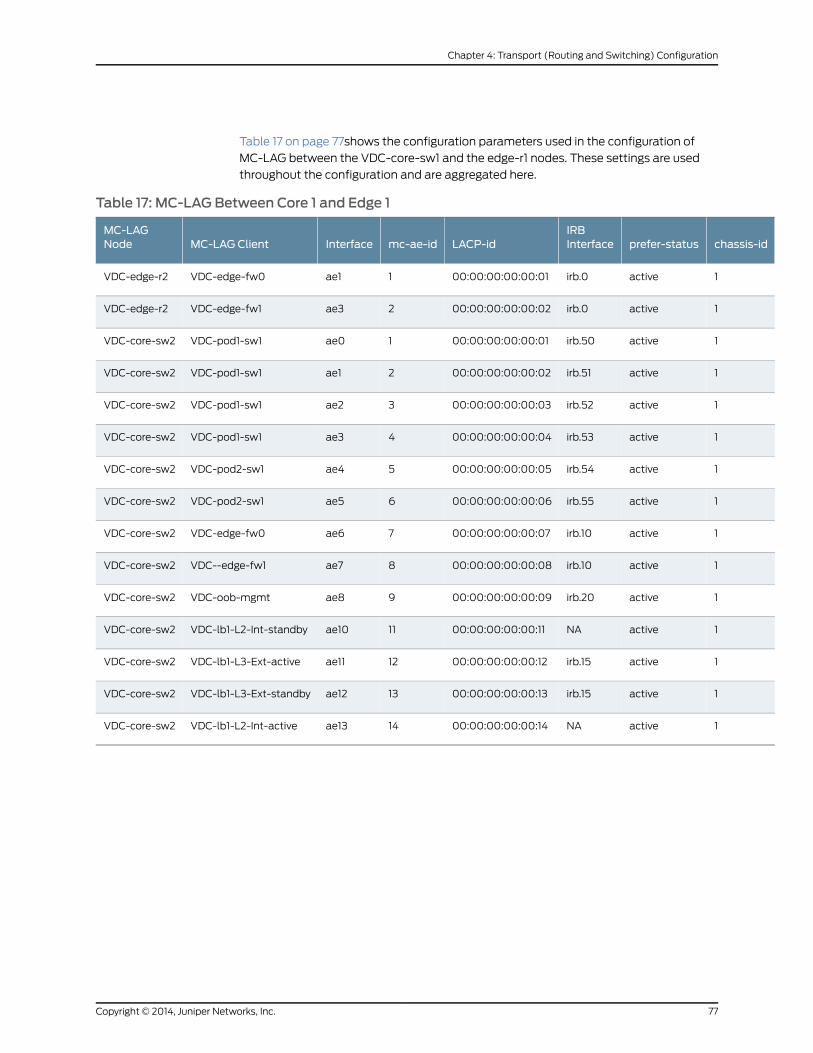
Table 17 on page 77shows the configuration parameters used in the configuration of
MC-LAG between the VDC-core-sw1 and the edge-r1 nodes. These settings are used
throughout the configuration and are aggregated here.
Table 17: MC-LAG Between Core 1 and Edge 1
chassis-idprefer-statusIRBInterfaceLACP-idmc-ae-idInterfaceMC-LAG Client
MC-LAGNode
1activeirb.000:00:00:00:00:011ae1VDC-edge-fw0VDC-edge-r2
1activeirb.000:00:00:00:00:022ae3VDC-edge-fw1VDC-edge-r2
1activeirb.5000:00:00:00:00:011ae0VDC-pod1-sw1VDC-core-sw2
1activeirb.5100:00:00:00:00:022ae1VDC-pod1-sw1VDC-core-sw2
1activeirb.5200:00:00:00:00:033ae2VDC-pod1-sw1VDC-core-sw2
1activeirb.5300:00:00:00:00:044ae3VDC-pod1-sw1VDC-core-sw2
1activeirb.5400:00:00:00:00:055ae4VDC-pod2-sw1VDC-core-sw2
1activeirb.5500:00:00:00:00:066ae5VDC-pod2-sw1VDC-core-sw2
1activeirb.1000:00:00:00:00:077ae6VDC-edge-fw0VDC-core-sw2
1activeirb.1000:00:00:00:00:088ae7VDC--edge-fw1VDC-core-sw2
1activeirb.2000:00:00:00:00:099ae8VDC-oob-mgmtVDC-core-sw2
1activeNA00:00:00:00:00:1111ae10VDC-lb1-L2-Int-standbyVDC-core-sw2
1activeirb.1500:00:00:00:00:1212ae11VDC-lb1-L3-Ext-activeVDC-core-sw2
1activeirb.1500:00:00:00:00:1313ae12VDC-lb1-L3-Ext-standbyVDC-core-sw2
1activeNA00:00:00:00:00:1414ae13VDC-lb1-L2-Int-activeVDC-core-sw2
77Copyright © 2014, Juniper Networks, Inc.
Chapter 4: Transport (Routing and Switching) Configuration

To configure the network between the data center edge and the data center core, follow
these steps:
1. Configure theSRXreth1 interfaceandmembers towardVDC-edge-r1andVDC-edge-r2.
set chassis cluster reth-count 4
2. Configure the MC-LAG bundle (ae1 and ae3) on VDC-edge-r1 toward the SRX .
set interfaces xe-1/1/0 gigether-options 802.3ad ae1set interfaces xe-1/1/1 gigether-options 802.3ad ae1##Configure ae1 MC-LAG A/A L2 Interface ####set interfaces ae1 description To-Firewall-reth1set interfaces ae1 flexible-vlan-taggingset interfaces ae1 encapsulation flexible-ethernet-servicesset interfaces ae1 aggregated-ether-options lacp activeset interfaces ae1 aggregated-ether-options lacp system-priority 100set interfaces ae1 aggregated-ether-options lacp system-id 00:00:00:00:00:01set interfaces ae1 aggregated-ether-options lacp admin-key 1set interfaces ae1 aggregated-ether-options mc-ae mc-ae-id 1set interfaces ae1 aggregated-ether-options mc-ae redundancy-group 1set interfaces ae1 aggregated-ether-options mc-ae chassis-id 0set interfaces ae1 aggregated-ether-options mc-ae mode active-activeset interfaces ae1 aggregated-ether-options mc-ae status-control activeset interfaces ae1 aggregated-ether-options mc-ae events iccp-peer-downforce-icl-downset interfaces ae1 aggregated-ether-options mc-ae events iccp-peer-downprefer-status-control-activeset interfaces ae1 unit 0 encapsulation vlan-bridgeset interfaces ae1 unit 0 vlan-id 11set interfaces ae1 unit 0 multi-chassis-protection 192.168.168.2 interfaceae0.1###Configured 2Member links for ae3###set interfaces xe-1/2/0 gigether-options 802.3ad ae3set interfaces xe-1/2/1 gigether-options 802.3ad ae3##Configure ae1 MC-LAG A/A L2 Interface ####set interfaces ae3 description To-Firewall-Standbyset interfaces ae3 flexible-vlan-taggingset interfaces ae3 encapsulation flexible-ethernet-servicesset interfaces ae3 aggregated-ether-options lacp activeset interfaces ae3 aggregated-ether-options lacp system-priority 100set interfaces ae3 aggregated-ether-options lacp system-id 00:00:00:00:00:03set interfaces ae3 aggregated-ether-options lacp admin-key 3set interfaces ae3 aggregated-ether-options mc-ae mc-ae-id 3set interfaces ae3 aggregated-ether-options mc-ae redundancy-group 1set interfaces ae3 aggregated-ether-options mc-ae chassis-id 0set interfaces ae3 aggregated-ether-options mc-ae mode active-activeset interfaces ae3 aggregated-ether-options mc-ae status-control activeset interfaces ae3 aggregated-ether-options mc-ae events iccp-peer-downforce-icl-downset interfaces ae3 aggregated-ether-options mc-ae events iccp-peer-downprefer-status-control-activeset interfaces ae3 unit 0 encapsulation vlan-bridgeset interfaces ae3 unit 0 vlan-id 11set interfaces ae3 unit 0 multi-chassis-protection 192.168.168.2 interfaceae0.1
3. Configure the bridge domain and IRB interfaces on VDC-edge-r1.
set bridge-domains bd1 domain-type bridgeset bridge-domains bd1 vlan-id 11set bridge-domains bd1 interface ae1.0 ###MC-LAG interface##set bridge-domains bd1 interface ae0.1 ### MC_LAG ICL link ###
Copyright © 2014, Juniper Networks, Inc.78
MetaFabric™ Architecture Virtualized Data Center

set bridge-domains bd1 interface ae3.0 ###MC-LAG interface##set bridge-domains bd1 routing-interface irb.0 ### L2/L3 routing interface######Configure the IRB interface for L2/L3 routing ##set interfaces irb unit 0 family inet address 192.168.26.1/24 arp 192.168.26.2l2-interface ae0.1set interfaces irb unit 0 family inet address 192.168.26.1/24 arp 192.168.26.2mac 50:c5:8d:87:af:f0set interfaces irb unit 0 family inet address 192.168.26.1/24 arp 192.168.26.2publishset interfaces irb unit 0 family inet address 192.168.26.1/24 vrrp-group 1virtual-address 192.168.26.254set interfaces irb unit 0 family inet address 192.168.26.1/24 vrrp-group 1priority 250set interfaces irb unit 0 family inet address 192.168.26.1/24 vrrp-group 1fast-interval 100set interfaces irb unit 0 family inet address 192.168.26.1/24 vrrp-group 1preemptset interfaces irb unit 0 family inet address 192.168.26.1/24 vrrp-group 1accept-dataset interfaces irb unit 0 family inet address 192.168.26.1/24 vrrp-group 1authentication-type md5set interfaces irb unit 0 family inet address 192.168.26.1/24 vrrp-group 1authentication-key "$9$WKVXVYaJDkqfoaFnCA0O"
4. Configure ICCP and ICL links for MC-LAG on vdc-edge-r1.
set interfaces ae0 flexible-vlan-taggingset interfaces ae0 encapsulation flexible-ethernet-servicesset interfaces ae0 aggregated-ether-options lacp activeset interfaces ae0 aggregated-ether-options lacp periodic slowset interfaces xe-1/0/0 hold-time up 100set interfaces xe-1/0/0 hold-time down 15000set interfaces xe-1/0/0 gigether-options 802.3ad ae0set interfaces xe-1/0/1 hold-time up 100set interfaces xe-1/0/1 hold-time down 15000set interfaces xe-1/0/1 gigether-options 802.3ad ae0
NOTE: Hold-down timer configured higher than the BFD timer(1 sec) forbetter convergence
set interfaces ae0 unit 0 description "ICCP Link between edge-r1 and edge-r2"set interfaces ae0 unit 0 vlan-id 4000set interfaces ae0 unit 0 vlan-id 4000set interfaces ae0 unit 0 family inet address 192.168.1.1/30set interfaces ae0 unit 1 description "ICL Link to edge-r2-vlan-11"set interfaces ae0 unit 1 encapsulation vlan-bridgeset interfaces ae0 unit 1 vlan-id 11
5. Configure the Inter-Control Center Communications Protocol (ICCP) on vdc-edge-r1.
set protocols iccp local-ip-addr 192.168.168.1set protocols iccp peer 192.168.168.2 redundancy-group-id-list 1set protocols iccp peer 192.168.168.2 liveness-detection minimum-interval 500set protocols iccp peer 192.168.168.2 liveness-detection multiplier 2set protocols iccp peer 192.168.168.2 liveness-detection detection-timethreshold 2000
NOTE: The BFD timer is configured as 1 second in this solution testing.This setting provided sub-2-second convergence in testing.
79Copyright © 2014, Juniper Networks, Inc.
Chapter 4: Transport (Routing and Switching) Configuration

6. Configure the MC-LAG bundle (ae1 and ae3) on VDC-edge-r2 toward the SRX.
set interfaces xe-1/1/0 gigether-options 802.3ad ae1set interfaces xe-1/1/1 gigether-options 802.3ad ae1set interfaces ae1 description To-Firewall-reth1set interfaces ae1 flexible-vlan-taggingset interfaces ae1 encapsulation flexible-ethernet-servicesset interfaces ae1 aggregated-ether-options lacp activeset interfaces ae1 aggregated-ether-options lacp system-priority 100set interfaces ae1 aggregated-ether-options lacp system-id 00:00:00:00:00:01set interfaces ae1 aggregated-ether-options lacp admin-key 1set interfaces ae1 aggregated-ether-options mc-ae mc-ae-id 1set interfaces ae1 aggregated-ether-options mc-ae redundancy-group 1set interfaces ae1 aggregated-ether-options mc-ae chassis-id 1set interfaces ae1 aggregated-ether-options mc-ae mode active-activeset interfaces ae1 aggregated-ether-options mc-ae status-control standbyset interfaces ae1 aggregated-ether-options mc-ae events iccp-peer-downforce-icl-downset interfaces ae1 unit 0 encapsulation vlan-bridgeset interfaces ae1 unit 0 vlan-id 11set interfaces ae1 unit 0 multi-chassis-protection 192.168.168.1 interfaceae0.1set interfaces xe-1/2/0 gigether-options 802.3ad ae3set interfaces xe-1/2/1 gigether-options 802.3ad ae3set interfaces ae3 description To-Firewall-reth1set interfaces ae3 flexible-vlan-taggingset interfaces ae3 encapsulation flexible-ethernet-servicesset interfaces ae3 aggregated-ether-options lacp activeset interfaces ae3 aggregated-ether-options lacp system-priority 100set interfaces ae3 aggregated-ether-options lacp system-id 00:00:00:00:00:03set interfaces ae3 aggregated-ether-options lacp admin-key 3set interfaces ae3 aggregated-ether-options mc-ae mc-ae-id 3set interfaces ae3 aggregated-ether-options mc-ae redundancy-group 1set interfaces ae3 aggregated-ether-options mc-ae chassis-id 1set interfaces ae3 aggregated-ether-options mc-ae mode active-activeset interfaces ae3 aggregated-ether-options mc-ae status-control standbyset interfaces ae3 aggregated-ether-options mc-ae events iccp-peer-downforce-icl-downset interfaces ae3 unit 0 encapsulation vlan-bridgeset interfaces ae3 unit 0 vlan-id 11set interfaces ae3 unit 0 multi-chassis-protection 192.168.168.1 interfaceae0.1
7. Configuring the bridge domain and IRB interface on VDC-edge-r2.
set bridge-domains bd1 domain-type bridgeset bridge-domains bd1 vlan-id 11set bridge-domains bd1 interface ae1.0set bridge-domains bd1 interface ae0.1set bridge-domains bd1 interface ae3.0set bridge-domains bd1 routing-interface irb.0set interfaces irb unit 0 family inet address 192.168.26.2/24 arp 192.168.26.1l2-interface ae0.1set interfaces irb unit 0 family inet address 192.168.26.2/24 arp 192.168.26.1mac 50:c5:8d:87:87:f0set interfaces irb unit 0 family inet address 192.168.26.2/24 arp 192.168.26.1publishset interfaces irb unit 0 family inet address 192.168.26.2/24 vrrp-group 1virtual-address 192.168.26.254set interfaces irb unit 0 family inet address 192.168.26.2/24 vrrp-group 1priority 125set interfaces irb unit 0 family inet address 192.168.26.2/24 vrrp-group 1fast-interval 100
Copyright © 2014, Juniper Networks, Inc.80
MetaFabric™ Architecture Virtualized Data Center
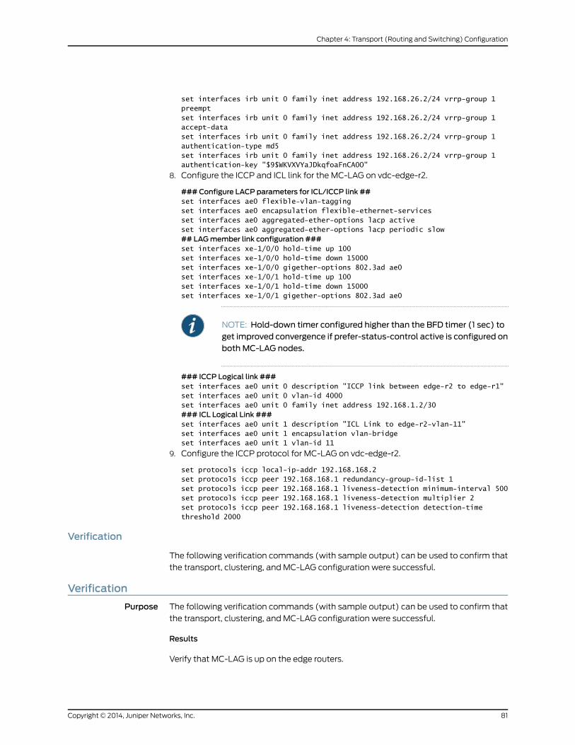
set interfaces irb unit 0 family inet address 192.168.26.2/24 vrrp-group 1preemptset interfaces irb unit 0 family inet address 192.168.26.2/24 vrrp-group 1accept-dataset interfaces irb unit 0 family inet address 192.168.26.2/24 vrrp-group 1authentication-type md5set interfaces irb unit 0 family inet address 192.168.26.2/24 vrrp-group 1authentication-key "$9$WKVXVYaJDkqfoaFnCA0O"
8. Configure the ICCP and ICL link for the MC-LAG on vdc-edge-r2.
###Configure LACP parameters for ICL/ICCP link ##set interfaces ae0 flexible-vlan-taggingset interfaces ae0 encapsulation flexible-ethernet-servicesset interfaces ae0 aggregated-ether-options lacp activeset interfaces ae0 aggregated-ether-options lacp periodic slow## LAGmember link configuration ###set interfaces xe-1/0/0 hold-time up 100set interfaces xe-1/0/0 hold-time down 15000set interfaces xe-1/0/0 gigether-options 802.3ad ae0set interfaces xe-1/0/1 hold-time up 100set interfaces xe-1/0/1 hold-time down 15000set interfaces xe-1/0/1 gigether-options 802.3ad ae0
NOTE: Hold-down timer configured higher than the BFD timer (1 sec) toget improved convergence if prefer-status-control active is configured onboth MC-LAG nodes.
### ICCP Logical link ###set interfaces ae0 unit 0 description "ICCP link between edge-r2 to edge-r1"set interfaces ae0 unit 0 vlan-id 4000set interfaces ae0 unit 0 family inet address 192.168.1.2/30### ICL Logical Link ###set interfaces ae0 unit 1 description "ICL Link to edge-r2-vlan-11"set interfaces ae0 unit 1 encapsulation vlan-bridgeset interfaces ae0 unit 1 vlan-id 11
9. Configure the ICCP protocol for MC-LAG on vdc-edge-r2.
set protocols iccp local-ip-addr 192.168.168.2set protocols iccp peer 192.168.168.1 redundancy-group-id-list 1set protocols iccp peer 192.168.168.1 liveness-detection minimum-interval 500set protocols iccp peer 192.168.168.1 liveness-detection multiplier 2set protocols iccp peer 192.168.168.1 liveness-detection detection-timethreshold 2000
Verification
The following verification commands (with sample output) can be used to confirm that
the transport, clustering, and MC-LAG configuration were successful.
Verification
Purpose The following verification commands (with sample output) can be used to confirm that
the transport, clustering, and MC-LAG configuration were successful.
Results
Verify that MC-LAG is up on the edge routers.
81Copyright © 2014, Juniper Networks, Inc.
Chapter 4: Transport (Routing and Switching) Configuration
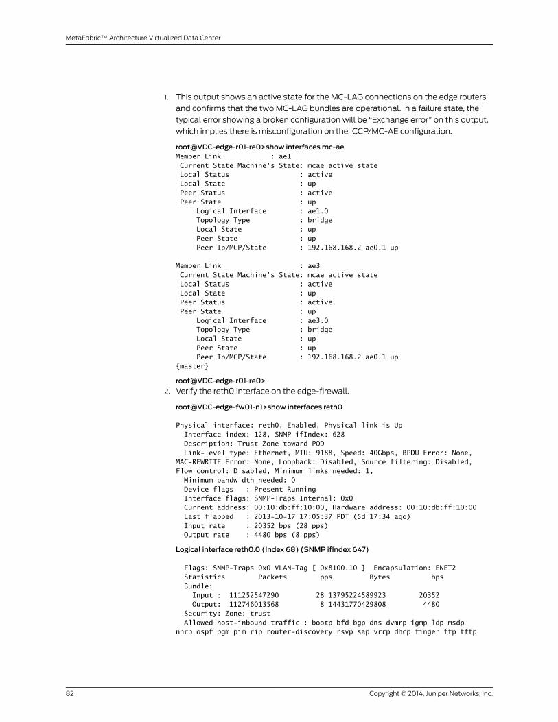
1. This output shows an active state for the MC-LAG connections on the edge routers
and confirms that the twoMC-LAG bundles are operational. In a failure state, the
typical error showing a broken configuration will be “Exchange error” on this output,
which implies there is misconfiguration on the ICCP/MC-AE configuration.
root@VDC-edge-r01-re0>show interfacesmc-aeMember Link : ae1 Current State Machine's State: mcae active state Local Status : active Local State : up Peer Status : active Peer State : up Logical Interface : ae1.0 Topology Type : bridge Local State : up Peer State : up Peer Ip/MCP/State : 192.168.168.2 ae0.1 up
Member Link : ae3 Current State Machine's State: mcae active state Local Status : active Local State : up Peer Status : active Peer State : up Logical Interface : ae3.0 Topology Type : bridge Local State : up Peer State : up Peer Ip/MCP/State : 192.168.168.2 ae0.1 up{master}
root@VDC-edge-r01-re0>
2. Verify the reth0 interface on the edge-firewall.
root@VDC-edge-fw01-n1>show interfaces reth0
Physical interface: reth0, Enabled, Physical link is Up Interface index: 128, SNMP ifIndex: 628 Description: Trust Zone toward POD Link-level type: Ethernet, MTU: 9188, Speed: 40Gbps, BPDU Error: None, MAC-REWRITE Error: None, Loopback: Disabled, Source filtering: Disabled, Flow control: Disabled, Minimum links needed: 1, Minimum bandwidth needed: 0 Device flags : Present Running Interface flags: SNMP-Traps Internal: 0x0 Current address: 00:10:db:ff:10:00, Hardware address: 00:10:db:ff:10:00 Last flapped : 2013-10-17 17:05:37 PDT (5d 17:34 ago) Input rate : 20352 bps (28 pps) Output rate : 4480 bps (8 pps)
Logical interface reth0.0 (Index 68) (SNMP ifIndex 647)
Flags: SNMP-Traps 0x0 VLAN-Tag [ 0x8100.10 ] Encapsulation: ENET2 Statistics Packets pps Bytes bps Bundle: Input : 111252547290 28 13795224589923 20352 Output: 112746013568 8 14431770429808 4480 Security: Zone: trust Allowed host-inbound traffic : bootp bfd bgp dns dvmrp igmp ldp msdp nhrp ospf pgm pim rip router-discovery rsvp sap vrrp dhcp finger ftp tftp
Copyright © 2014, Juniper Networks, Inc.82
MetaFabric™ Architecture Virtualized Data Center

ident-reset http https ike netconf ping reverse-telnet reverse-ssh rlogin rpm rsh snmp snmp-trap ssh telnet traceroute xnm-clear-text xnm-ssl lsping ntp sip r2cp Protocol inet, MTU: 9170 Flags: Sendbcast-pkt-to-re Addresses, Flags: Is-Preferred Is-Primary Destination: 192.168.25/24, Local: 192.168.25.3, Broadcast: 192.168.25.255 Protocol multiservice, MTU: Unlimited Flags: Is-Primary
Logical interface reth0.32767 (Index 67) (SNMP ifIndex 662)
Flags: SNMP-Traps 0x0 VLAN-Tag [ 0x0000.0 ] Encapsulation: ENET2Statistics Packets pps Bytes bpsBundle: Input : 0 0 0 0 Output: 0 0 0 0Security: Zone: NullProtocol multiservice, MTU: Unlimited Flags: None
3. Verify that the edge router is selecting the active firewall node for traffic forwarding.
This selection is done based on the gratuitous ARP request sent by the active SRX
firewall.
a. Check the route for the firewall reth0 IP address.
root@VDC-edge-r01-re0>show route 192.168.26.3
inet.0: 66 destinations, 77 routes (66 active, 0 holddown, 0 hidden)+ = Active Route, - = Last Active, * = Both
192.168.26.0/24 *[Direct/0] 1w6d 23:12:12 > via irb.0
b. Check the forwarding table to see if the next hopand interfaceare chosen correctly
Active firewall node (Node 2 is active)root@VDC-edge-r01-re0> show route forwarding-table destination 192.168.26.3
Routing table: default.inetInternet:Destination Type RtRef Next hop Type Index NhRef Netif192.168.26.3/32 dest 0 0:10:db:ff:10:1 ucst 597 39 ae3.0Routing table: __master.anon__.inetInternet:Destination Type RtRef Next hop Type Index NhRef Netifdefault perm 0 rjct 519 1
83Copyright © 2014, Juniper Networks, Inc.
Chapter 4: Transport (Routing and Switching) Configuration
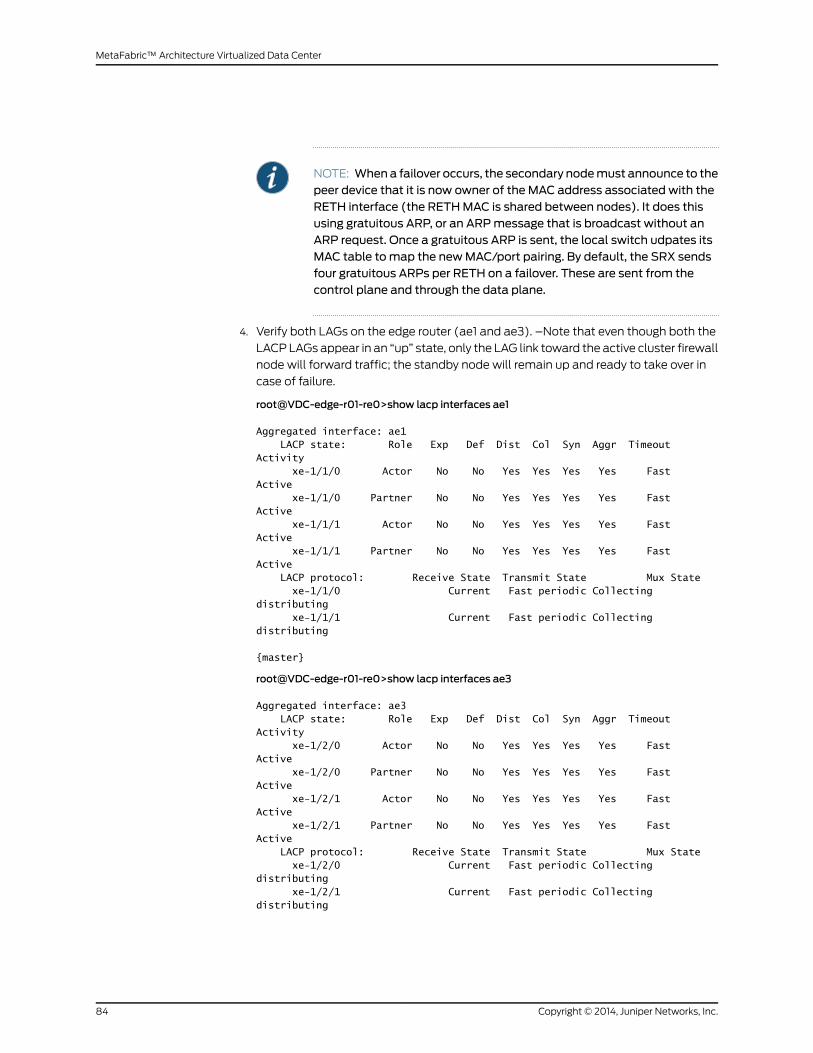
NOTE: Whena failover occurs, the secondary nodemust announce to thepeer device that it is now owner of the MAC address associated with theRETH interface (the RETHMAC is shared between nodes). It does thisusing gratuitous ARP, or an ARPmessage that is broadcast without anARP request. Once a gratuitous ARP is sent, the local switch udpates itsMAC table tomap the newMAC/port pairing. By default, the SRX sendsfour gratuitous ARPs per RETH on a failover. These are sent from thecontrol plane and through the data plane.
4. Verify both LAGs on the edge router (ae1 and ae3). –Note that even though both the
LACPLAGs appear in an “up” state, only the LAG link toward the active cluster firewall
node will forward traffic; the standby node will remain up and ready to take over in
case of failure.
root@VDC-edge-r01-re0>show lacp interfaces ae1
Aggregated interface: ae1 LACP state: Role Exp Def Dist Col Syn Aggr Timeout Activity xe-1/1/0 Actor No No Yes Yes Yes Yes Fast Active xe-1/1/0 Partner No No Yes Yes Yes Yes Fast Active xe-1/1/1 Actor No No Yes Yes Yes Yes Fast Active xe-1/1/1 Partner No No Yes Yes Yes Yes Fast Active LACP protocol: Receive State Transmit State Mux State xe-1/1/0 Current Fast periodic Collecting distributing xe-1/1/1 Current Fast periodic Collecting distributing
{master}
root@VDC-edge-r01-re0>show lacp interfaces ae3
Aggregated interface: ae3 LACP state: Role Exp Def Dist Col Syn Aggr Timeout Activity xe-1/2/0 Actor No No Yes Yes Yes Yes Fast Active xe-1/2/0 Partner No No Yes Yes Yes Yes Fast Active xe-1/2/1 Actor No No Yes Yes Yes Yes Fast Active xe-1/2/1 Partner No No Yes Yes Yes Yes Fast Active LACP protocol: Receive State Transmit State Mux State xe-1/2/0 Current Fast periodic Collecting distributing xe-1/2/1 Current Fast periodic Collecting distributing
Copyright © 2014, Juniper Networks, Inc.84
MetaFabric™ Architecture Virtualized Data Center

ImplementingMC-LAG Active/Active with VRRP
To allow all the links to forward traffic without being blocked by spanning-tree,
multi-chassis link aggregation (MC-LAG) is configured on the edge routers and core
switches. The edge routers useMC-LAG toward the edge firewalls, and the core switches
use MC-LAG toward each POD switch, application load balancer (F5), and OOB
management switch. MC- is a feature that supports aggregated Ethernet (AE) LAG
bundles spread across more than one device. LACP is used for dynamic configuration
andmonitoring on links.
Summary of Implementation Details for MC-LAG Active/Active
MC-LAG is a key component of the MetaFabric 1.0 solution architecture. MC-LAG is
configured using the following design considerations:
• Do not mix Layer 2 next generation CLI syntax (L2NG, or family ethernet-switching)
and non-l2ng (flexible-ethernet-serivces) syntax on the same interface.
• Mac-learning is disabled on inter-chassis link (ICL).
• Arp learning is disabled on ICL.
• Static arp is required for integrated routing and bridging (IRB)-to-IRB connectivity
across the ICL.
This is configured to support OSPF over the Inter-Control Center Communications
Protocol (ICCP).
• Load balancing betweenmc-lag peers is 100 percent local bias by default.
• Load balancing within local peer is the same as normal lag hashing.
• Two possible options for Layer 3 gateway is Virtual Router Redundancy Protocol
(VRRP) based or irb-mac-sync.
• If irb-mac-sync is used, routing protocols on IRB are not supported.
• In a VRRP-based Layer 3 solution, even the VRRP backup node forwards traffic.
• Prefer separate link aggregation group (LAG) links for ICL and ICCP.
• ICCP peering with loopback IP is preferred to use all available links through interior
gateway protocol (IGP).
• Configure backup-liveness detection to get sub-second traffic loss during MC-LAG
peer switch reboots.
• Spanning Tree Protocol (STP) is not supported on ICL or MC-LAG interfaces.
• Access security features are not supported on ICL or MC-LAG interfaces.
• Configuremcaewith “prefer status control active” on both provider edge routers (PEs)
to avoid lacp system ID flap during active node (SW) reboot.
85Copyright © 2014, Juniper Networks, Inc.
Chapter 4: Transport (Routing and Switching) Configuration
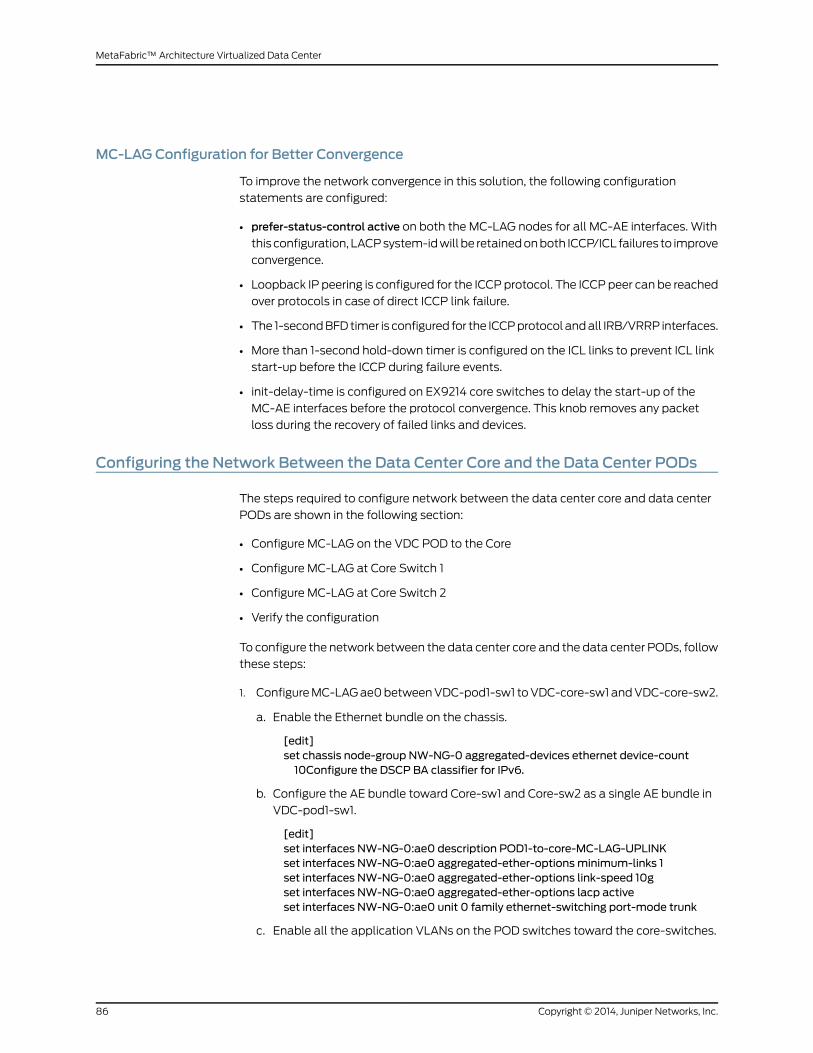
MC-LAG Configuration for Better Convergence
To improve the network convergence in this solution, the following configuration
statements are configured:
• prefer-status-control active on both the MC-LAG nodes for all MC-AE interfaces. With
this configuration, LACPsystem-idwill be retainedonboth ICCP/ICL failures to improve
convergence.
• Loopback IP peering is configured for the ICCPprotocol. The ICCPpeer can be reached
over protocols in case of direct ICCP link failure.
• The 1-secondBFDtimer is configured for the ICCPprotocol andall IRB/VRRP interfaces.
• More than 1-second hold-down timer is configured on the ICL links to prevent ICL link
start-up before the ICCP during failure events.
• init-delay-time is configured on EX9214 core switches to delay the start-up of the
MC-AE interfaces before the protocol convergence. This knob removes any packet
loss during the recovery of failed links and devices.
Configuring the Network Between the Data Center Core and the Data Center PODs
The steps required to configure network between the data center core and data center
PODs are shown in the following section:
• Configure MC-LAG on the VDC POD to the Core
• Configure MC-LAG at Core Switch 1
• Configure MC-LAG at Core Switch 2
• Verify the configuration
To configure the network between the data center core and the data center PODs, follow
these steps:
1. ConfigureMC-LAGae0betweenVDC-pod1-sw1 toVDC-core-sw1andVDC-core-sw2.
a. Enable the Ethernet bundle on the chassis.
[edit]set chassis node-group NW-NG-0 aggregated-devices ethernet device-count10Configure the DSCP BA classifier for IPv6.
b. Configure the AE bundle toward Core-sw1 and Core-sw2 as a single AE bundle in
VDC-pod1-sw1.
[edit]set interfaces NW-NG-0:ae0 description POD1-to-core-MC-LAG-UPLINKset interfaces NW-NG-0:ae0 aggregated-ether-optionsminimum-links 1set interfaces NW-NG-0:ae0 aggregated-ether-options link-speed 10gset interfaces NW-NG-0:ae0 aggregated-ether-options lacp activeset interfaces NW-NG-0:ae0 unit 0 family ethernet-switching port-mode trunk
c. Enable all the application VLANs on the POD switches toward the core-switches.
Copyright © 2014, Juniper Networks, Inc.86
MetaFabric™ Architecture Virtualized Data Center

[edit]set interfacesNW-NG-0:ae0unit 0 family ethernet-switching vlanmembersMGMTset interfaces NW-NG-0:ae0 unit 0 family ethernet-switching vlanmembers Infraset interfacesNW-NG-0:ae0unit0familyethernet-switchingvlanmembersTera-VMset interfaces NW-NG-0:ae0 unit 0 family ethernet-switching vlanmembersSecurity-Mgmt
set interfacesNW-NG-0:ae0unit0familyethernet-switchingvlanmembersVmotionset interfacesNW-NG-0:ae0unit 0 family ethernet-switching vlanmembersVM-FTset interfaces NW-NG-0:ae0 unit 0 family ethernet-switching vlanmembersRemote-Access
set interfaces NW-NG-0:ae0 unit 0 family ethernet-switching vlanmembersCore-transport-1
d. Configure the member links connected to Core-sw1 and Core-sw2 under the AE
bundle.
NOTE: n0:xe-0/0/[0-11] is connected to VDC-core-sw1.
n1:xe-0/0/[0-11] is connected to VDC-core-sw2.
[edit]set interfaces interface-rangeMC-LAG-ae0-membersmember "n0:xe-0/0/[0-11]"set interfaces interface-range MC-LAG-ae0-members member "n1:xe-0/0/[0-11]"set interfaces interface-range MC-LAG-ae0-members description "MC-LAG toCore-sw ae0"
set interfaces interface-range MC-LAG-ae0-members ether-options 802.3adNW-NG-0:ae0
e. Configure MC-LAG ae0 between VDC-pod1-sw1 to VDC-core-sw1 and
VDC-core-sw2 and enable Ethernet bundle on the chassis:
[edit]set chassis node-group NW-NG-0 aggregated-devices ethernet device-count10Configure the DSCP BA classifier for IPv6.
f. Configure the AE bundle toward Core-sw1 and Core-sw2 as a single AE bundle in
VDC-pod1-sw1.
[edit]set interfaces NW-NG-0:ae0 description POD1-to-core-MC-LAG-UPLINKset interfaces NW-NG-0:ae0 aggregated-ether-optionsminimum-links 1set interfaces NW-NG-0:ae0 aggregated-ether-options link-speed 10gset interfaces NW-NG-0:ae0 aggregated-ether-options lacp activeset interfaces NW-NG-0:ae0 unit 0 family ethernet-switching port-mode trunk
g. Enable all the applications VLAN on the POD switches toward the core-switches.
[edit]set interfacesNW-NG-0:ae0unit 0 family ethernet-switching vlanmembersMGMTset interfaces NW-NG-0:ae0 unit 0 family ethernet-switching vlanmembers Infraset interfacesNW-NG-0:ae0unit0familyethernet-switchingvlanmembersTera-VMset interfaces NW-NG-0:ae0 unit 0 family ethernet-switching vlanmembersSecurity-Mgmt
set interfacesNW-NG-0:ae0unit0familyethernet-switchingvlanmembersVmotionset interfacesNW-NG-0:ae0unit 0 family ethernet-switching vlanmembersVM-FT
87Copyright © 2014, Juniper Networks, Inc.
Chapter 4: Transport (Routing and Switching) Configuration

set interfaces NW-NG-0:ae0 unit 0 family ethernet-switching vlanmembersRemote-Access
set interfaces NW-NG-0:ae0 unit 0 family ethernet-switching vlanmembersCore-transport-1
h. Configure the member links connected to Core-sw1 and Core-sw2 under the AE
bundle.
i. [edit]set interfaces interface-rangeMC-LAG-ae0-membersmember "n0:xe-0/0/[0-11]"set interfaces interface-range MC-LAG-ae0-members member "n1:xe-0/0/[0-11]"set interfaces interface-range MC-LAG-ae0-members description "MC-LAG toCore-sw ae0"
set interfaces interface-range MC-LAG-ae0-members ether-options 802.3adNW-NG-0:ae0
NOTE: n0:xe-0/0/[0-11] is connected to VDC-core-sw1
n1:xe-0/0/[0-11] is connected to VDC-core-sw2
2. Configure MC-LAG at VDC-core-sw1 (EX9214-1).
a. Specify the number of aggregated Ethernet interfaces to be created.
[edit]set chassis aggregated-devices ethernet device-count 30
b. Specify the members to be included within the aggregated Ethernet bundle ae0.
[edit]set interfaces NW-NG-0:ae0 description POD1-to-core-MC-LAG-UPLINKset interfaces NW-NG-0:ae0 aggregated-ether-optionsminimum-links 1set interfaces NW-NG-0:ae0 aggregated-ether-options link-speed 10gset interfaces NW-NG-0:ae0 aggregated-ether-options lacp activeset interfaces NW-NG-0:ae0 unit 0 family ethernet-switching port-mode trunk
c. ConfigureLACPparameterswith static system-idandadmin-keyon theaggregated
Ethernet bundle.
[edit]set interfaces ae0 description "MC-LAG to VDC-pod1-sw1-nng-ae0"set interfaces ae0 aggregated-ether-options lacp activeset interfaces ae0 aggregated-ether-options lacp system-priority 100set interfaces ae0 aggregated-ether-options lacp system-id 00:00:00:00:00:01set interfaces ae0 aggregated-ether-options lacp admin-key 1
d. Configure MC-AE interface parameters.
[edit]set interfaces ae0 aggregated-ether-optionsmc-aemc-ae-id 1set interfaces ae0 aggregated-ether-optionsmc-ae redundancy-group 1set interfaces ae0 aggregated-ether-optionsmc-ae chassis-id 0set interfaces ae0 aggregated-ether-optionsmc-aemode active-activeset interfaces ae0 aggregated-ether-optionsmc-ae status-control activeset interfaces ae0 aggregated-ether-optionsmc-ae init-delay-time 520set interfaces ae0 aggregated-ether-optionsmc-ae events iccp-peer-downforce-icl-down
Copyright © 2014, Juniper Networks, Inc.88
MetaFabric™ Architecture Virtualized Data Center
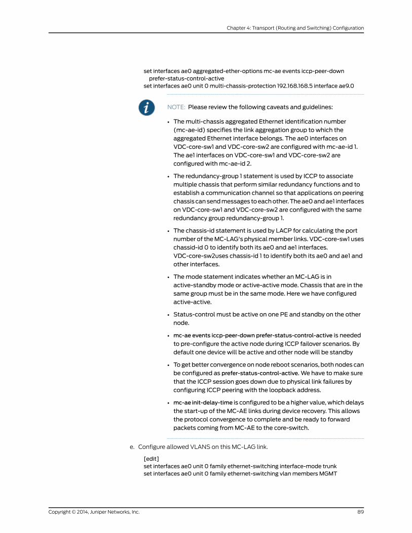
set interfaces ae0 aggregated-ether-optionsmc-ae events iccp-peer-downprefer-status-control-active
set interfaces ae0 unit 0multi-chassis-protection 192.168.168.5 interface ae9.0
NOTE: Please review the following caveats and guidelines:
• Themulti-chassis aggregated Ethernet identification number(mc-ae-id) specifies the link aggregation group to which theaggregated Ethernet interface belongs. The ae0 interfaces onVDC-core-sw1 and VDC-core-sw2 are configured withmc-ae-id 1.The ae1 interfaces on VDC-core-sw1 and VDC-core-sw2 areconfigured withmc-ae-id 2.
• The redundancy-group 1 statement is used by ICCP to associatemultiple chassis that perform similar redundancy functions and toestablish a communication channel so that applications on peeringchassis cansendmessages toeachother.Theae0andae1 interfaceson VDC-core-sw1 and VDC-core-sw2 are configured with the sameredundancy group redundancy-group 1.
• The chassis-id statement is used by LACP for calculating the portnumber of theMC-LAG's physicalmember links. VDC-core-sw1 useschassid-id 0 to identify both its ae0 and ae1 interfaces.VDC-core-sw2uses chassis-id 1 to identify both its ae0 and ae1 andother interfaces.
• Themode statement indicates whether an MC-LAG is inactive-standbymode or active-activemode. Chassis that are in thesame groupmust be in the samemode. Here we have configuredactive-active.
• Status-control must be active on one PE and standby on the othernode.
• mc-ae events iccp-peer-down prefer-status-control-active is needed
to pre-configure the active node during ICCP failover scenarios. Bydefault one device will be active and other node will be standby
• Toget better convergenceonnode reboot scenarios, both nodes canbe configured as prefer-status-control-active. We have tomake sure
that the ICCP session goes down due to physical link failures byconfiguring ICCP peering with the loopback address.
• mc-ae init-delay-time is configured to be a higher value,which delays
the start-up of the MC-AE links during device recovery. This allowsthe protocol convergence to complete and be ready to forwardpackets coming fromMC-AE to the core-switch.
e. Configure allowed VLANS on this MC-LAG link.
[edit]set interfaces ae0 unit 0 family ethernet-switching interface-mode trunkset interfaces ae0 unit 0 family ethernet-switching vlanmembers MGMT
89Copyright © 2014, Juniper Networks, Inc.
Chapter 4: Transport (Routing and Switching) Configuration

set interfaces ae0 unit 0 family ethernet-switching vlanmembers Infraset interfaces ae0 unit 0 family ethernet-switching vlanmembers Tera-VMset interfaces ae0 unit 0 family ethernet-switching vlanmembers Security-Mgmtset interfaces ae0 unit 0 family ethernet-switching vlanmembers Vmotionset interfaces ae0 unit 0 family ethernet-switching vlanmembers VM-FTset interfaces ae0 unit 0 family ethernet-switching vlanmembers Remote-Accessset interfacesae0unit0 family ethernet-switching vlanmembersPOD1-Transport-1
f. Configure ae bundle (ae20) connected between the core switches as a Layer 3
link to enable ICCP.
[edit]set interfaces ae20 vlan-taggingset interfaces ae20 aggregated-ether-options lacp activeset interfaces ae20 unit 0 description " ICCP link between core-sw1 and core-sw2"set interfaces ae20 unit 0 vlan-id 4000set interfaces ae20 unit 0 family inet address 192.168.2.1/30
g. Configure another ae bundle (ae9) connected between the core switches as a
Layer 2 link . Thiswill functionas themulti-chassis protection link (ICL-PL)between
the core switches.
[edit]set interfaces ae9 aggregated-ether-options lacp activeset interfaces ae9 aggregated-ether-options lacp periodic fastset interfaces ae9 unit 0 description "ICL Link for all VLANS"set interfaces ae9 unit 0 family ethernet-switching interface-mode trunk
h. Configure the ICL link members with a hold-time value higher than the configured
BFD timer(1s) to have zero loss convergence during recovery of failed devices.
[edit]set interfaces xe-0/3/6 hold-time up 100set interfaces xe-0/3/6 hold-time down 3000set interfaces xe-0/3/7 hold-time up 100set interfaces xe-0/3/7 hold-time down 3000set interfaces xe-1/3/6 hold-time up 100set interfaces xe-1/3/6 hold-time down 3000set interfaces xe-1/3/7 hold-time up 100set interfaces xe-1/3/7 hold-time down 3000set interfaces xe-3/3/6 hold-time up 100set interfaces xe-3/3/6 hold-time down 3000set interfaces xe-3/3/7 hold-time up 100set interfaces xe-3/3/7 hold-time down 3000set interfaces xe-5/3/6 hold-time up 100set interfaces xe-5/3/6 hold-time down 3000set interfaces xe-5/3/7 hold-time up 100set interfaces xe-5/3/7 hold-time down 3000
i. Configure allowed VLANs on this bundle.
[edit]set interfaces ae9 unit 0 family ethernet-switching vlanmembers Exchangeset interfaces ae9 unit 0 family ethernet-switching vlanmembers Infraset interfaces ae9 unit 0 family ethernet-switching vlanmembers SQLset interfaces ae9 unit 0 family ethernet-switching vlanmembers SharePointset interfaces ae9 unit 0 family ethernet-switching vlanmembers Firewallset interfaces ae9 unit 0 family ethernet-switching vlanmembers MGMT
Copyright © 2014, Juniper Networks, Inc.90
MetaFabric™ Architecture Virtualized Data Center

set interfaces ae9 unit 0 family ethernet-switching vlanmembersWikimediaset interfacesae9unit 0 family ethernet-switching vlanmembersExchange-Clusterset interfaces ae9 unit 0 family ethernet-switching vlanmembers Tera-VMset interfacesae9unit0 familyethernet-switchingvlanmembersLoad-balancer-Extset interfaces ae9 unit 0 family ethernet-switching vlanmembers Security-Mgmtset interfaces ae9 unit 0 family ethernet-switching vlanmembers Vmotionset interfaces ae9 unit 0 family ethernet-switching vlanmembers VM-FTset interfaces ae9 unit 0 family ethernet-switching vlanmembers Remote-Accessset interfaces ae9 unit 0 family ethernet-switching vlanmembers OOB-Transportset interfaces ae9 unit 0 family ethernet-switching vlanmembersLoad-balancer-Ext-Tera-VM
set interfaces ae9 unit 0 family ethernet-switching vlanmembersTrafficGenerator-502
set interfaces ae9 unit 0 family ethernet-switching vlanmembersTrafficGenerator-503
set interfaces ae9 unit 0 family ethernet-switching vlanmembersTrafficGenerator-504
set interfacesae9unit 0 family ethernet-switching vlanmembersPOD1-Transport-1set interfacesae9unit0 familyethernet-switchingvlanmembersPOD1-Transport-2set interfacesae9unit0 familyethernet-switchingvlanmembersPOD1-Transport-3set interfacesae9unit0 familyethernet-switchingvlanmembersPOD1-Transport-4set interfacesae9unit0 familyethernet-switchingvlanmembersPOD2-Transport-1set interfacesae9unit0 familyethernet-switchingvlanmembersPOD2-Transport-2
j. Configure IRB on both the core-sw1 and core-sw2 and enable VRRP on the IRBs.
[edit]set interfaces irb unit 50 family inet address 192.168.50.1/24 arp 192.168.50.2l2-interface ae9.0
set interfaces irb unit 50 family inet address 192.168.50.1/24 arp 192.168.50.2 mac4c:96:14:68:83:f0
set interfaces irbunit50family inetaddress 192.168.50.1/24arp 192.168.50.2publishset interfaces irb unit 50 family inet address 192.168.50.1/24 vrrp-group 1virtual-address 192.168.50.254
set interfaces irb unit 50 family inet address 192.168.50.1/24 vrrp-group 1 priority 125set interfaces irbunit 50 family inetaddress 192.168.50.1/24vrrp-group 1 fast-interval100
set interfaces irb unit 50 family inet address 192.168.50.1/24 vrrp-group 1 preemptset interfaces irbunit50 family inetaddress 192.168.50.1/24vrrp-group 1accept-dataset interfaces irb unit 50 family inet address 192.168.50.1/24 vrrp-group 1authentication-typemd5
set interfaces irb unit 50 family inet address 192.168.50.1/24 vrrp-group 1authentication-key "$9$Asx6uRSKvLN-weK4aUDkq"
k. Configure VLAN and enable “domain-type bridge” to configure IRB as the
routing-interface under this bridge domain.
[edit]set vlans POD1-Transport-1 vlan-id 50set vlans POD1-Transport-1 l3-interface irb.50set vlans POD1-Transport-1 domain-type bridge
91Copyright © 2014, Juniper Networks, Inc.
Chapter 4: Transport (Routing and Switching) Configuration

NOTE: The enhanced Layer 2 software (ELS) CLI doesn’t need anMC-AE interface, ICL under the bridge configuration. It picks theappropriate MC-AE interface from the VLAN association on theconfigured links.
l. Configure ICCP protocol parameters.
[edit]set protocols iccp local-ip-addr 192.168.168.4set protocols iccp peer 192.168.168.5 redundancy-group-id-list 1set protocols iccp peer 192.168.168.5 backup-liveness-detection backup-peer-ip192.168.168.5
set protocols iccp peer 192.168.168.5 liveness-detectionminimum-interval 500set protocols iccp peer 192.168.168.5 liveness-detectionmultiplier 2
m. Configure the switch service-id for MC-LAG.
[edit]set switch-options service-id 1
NOTE: Youmustconfigurethesameuniquenetwork-wideconfigurationfor a service in the set of PE routers providing the service. This serviceID is required if themulti-chassis aggregated Ethernet interfaces arepart of a bridge domain.
3. Configure MC-LAG at VDC-core-sw2 (EX9214-2).
a. Specify the number of aggregated Ethernet interfaces to be created.
[edit]set chassis aggregated-devices ethernet device-count 30
b. Specify the members to be included within the aggregated Ethernet bundle ae0.
[edit]set interfaces interface-rangePOD1-MC-LAG-ae0-membersmember"xe-0/0/[0-7]"set interfaces interface-rangePOD1-MC-LAG-ae0-membersmember"xe-0/1/[0-3]"set interfaces interface-range POD1-MC-LAG-ae0-members description "MC-LAGto POD1 ae0"
set interfaces interface-rangePOD1-MC-LAG-ae0-membersether-options802.3adae0
c. ConfigureLACPparameterswith static system-idandadmin-keyon theaggregated
Ethernet bundle.
[editset interfaces ae0 description "MC-LAG to VDC-pod1-sw1-nng-ae0"set interfaces ae0 aggregated-ether-options lacp activeset interfaces ae0 aggregated-ether-options lacp system-priority 100set interfaces ae0 aggregated-ether-options lacp system-id 00:00:00:00:00:01set interfaces ae0 aggregated-ether-options lacp admin-key 1
d. Configure MC-AE interface parameters.
[edit]
Copyright © 2014, Juniper Networks, Inc.92
MetaFabric™ Architecture Virtualized Data Center

set interfaces ae0 aggregated-ether-optionsmc-aemc-ae-id 1set interfaces ae0 aggregated-ether-optionsmc-ae redundancy-group 1set interfaces ae0 aggregated-ether-optionsmc-ae chassis-id 1set interfaces ae0 aggregated-ether-optionsmc-aemode active-activeset interfaces ae0 aggregated-ether-optionsmc-ae status-control standbyset interfaces ae0 aggregated-ether-optionsmc-ae init-delay-time 520set interfaces ae0 aggregated-ether-optionsmc-ae events iccp-peer-downforce-icl-down
set interfaces ae0 aggregated-ether-optionsmc-ae events iccp-peer-downprefer-status-control-active
set interfaces ae0 unit 0multi-chassis-protection 192.168.168.4 interface ae9.0
e. Configure allowed VLANS on this MC-LAG link.
[edit]set interfaces ae0 unit 0 family ethernet-switching interface-mode trunkset interfaces ae0 unit 0 family ethernet-switching vlanmembers MGMTset interfaces ae0 unit 0 family ethernet-switching vlanmembers Infraset interfaces ae0 unit 0 family ethernet-switching vlanmembers Tera-VMset interfaces ae0 unit 0 family ethernet-switching vlanmembers Security-Mgmtset interfaces ae0 unit 0 family ethernet-switching vlanmembers Vmotionset interfaces ae0 unit 0 family ethernet-switching vlanmembers VM-FTset interfaces ae0 unit 0 family ethernet-switching vlanmembers Remote-Accessset interfacesae0unit0 family ethernet-switching vlanmembersPOD1-Transport-1
f. Configure ae bundle (ae20) connected between the core switches as a Layer 3
link to enable ICCP.
[edit]set interfaces NW-NG-0:ae0 description POD1-to-core-MC-LAG-UPLINKset interfaces NW-NG-0:ae0 aggregated-ether-optionsminimum-links 1set interfaces NW-NG-0:ae0 aggregated-ether-options link-speed 10gset interfaces NW-NG-0:ae0 aggregated-ether-options lacp activeset interfaces NW-NG-0:ae0 unit 0 family ethernet-switching port-mode trunk
g. Configure ae bundle (ae9) connected between the core switches as a Layer 2 link.
This will function as the multi-chassis protection link between the core switches.
[edit]set interfaces ae9 aggregated-ether-options lacp activeset interfaces ae9 aggregated-ether-options lacp periodic fastset interfaces ae9 unit 0 description "ICL Link for all VLANS"set interfaces ae9 unit 0 family ethernet-switching interface-mode trunkset interfaces ae9 unit 0 family ethernet-switching vlanmembers Exchangeset interfaces ae9 unit 0 family ethernet-switching vlanmembers Infraset interfaces ae9 unit 0 family ethernet-switching vlanmembers SQLset interfaces ae9 unit 0 family ethernet-switching vlanmembers SharePointset interfaces ae9 unit 0 family ethernet-switching vlanmembers Firewallset interfaces ae9 unit 0 family ethernet-switching vlanmembers MGMTset interfaces ae9 unit 0 family ethernet-switching vlanmembersWikimediaset interfacesae9unit 0 family ethernet-switching vlanmembersExchange-Clusterset interfaces ae9 unit 0 family ethernet-switching vlanmembers Tera-VMset interfacesae9unit0 familyethernet-switchingvlanmembersLoad-balancer-Extset interfaces ae9 unit 0 family ethernet-switching vlanmembers Security-Mgmtset interfaces ae9 unit 0 family ethernet-switching vlanmembers Vmotionset interfaces ae9 unit 0 family ethernet-switching vlanmembers VM-FTset interfaces ae9 unit 0 family ethernet-switching vlanmembers Remote-Access
93Copyright © 2014, Juniper Networks, Inc.
Chapter 4: Transport (Routing and Switching) Configuration

set interfaces ae9 unit 0 family ethernet-switching vlanmembers OOB-Transportset interfaces ae9 unit 0 family ethernet-switching vlanmembersLoad-balancer-Ext-Tera-VM
set interfaces ae9 unit 0 family ethernet-switching vlanmembersTrafficGenerator-502
set interfaces ae9 unit 0 family ethernet-switching vlanmembersTrafficGenerator-503
set interfaces ae9 unit 0 family ethernet-switching vlanmembersTrafficGenerator-504
set interfacesae9unit 0 family ethernet-switching vlanmembersPOD1-Transport-1set interfacesae9unit0 familyethernet-switchingvlanmembersPOD1-Transport-2set interfacesae9unit0 familyethernet-switchingvlanmembersPOD1-Transport-3set interfacesae9unit0 familyethernet-switchingvlanmembersPOD1-Transport-4set interfacesae9unit0 familyethernet-switchingvlanmembersPOD2-Transport-1set interfacesae9unit0 familyethernet-switchingvlanmembersPOD2-Transport-2
h. Configure the ICL link members with a hold-time value higher than the configured
BFD timer(1s) to have zero loss convergence during recovery of failed devices.
[edit]set interfaces xe-0/3/6 hold-time up 100set interfaces xe-0/3/6 hold-time down 3000set interfaces xe-0/3/7 hold-time up 100set interfaces xe-0/3/7 hold-time down 3000set interfaces xe-1/3/6 hold-time up 100set interfaces xe-1/3/6 hold-time down 3000set interfaces xe-1/3/7 hold-time up 100set interfaces xe-1/3/7 hold-time down 3000set interfaces xe-3/3/6 hold-time up 100set interfaces xe-3/3/6 hold-time down 3000set interfaces xe-3/3/7 hold-time up 100set interfaces xe-3/3/7 hold-time down 3000set interfaces xe-5/3/6 hold-time up 100set interfaces xe-5/3/6 hold-time down 3000set interfaces xe-5/3/7 hold-time up 100set interfaces xe-5/3/7 hold-time down 3000
i. Configure IRB on both the core-sw1 and core-sw2 and enable VRRP.
[edit]set interfaces irb unit 50 family inet address 192.168.50.2/24 arp 192.168.50.1l2-interface ae9.0
set interfaces irb unit 50 family inet address 192.168.50.2/24 arp 192.168.50.1 mac4c:96:14:6b:db:f0
set interfaces irbunit50family inetaddress 192.168.50.2/24arp 192.168.50.1publishset interfaces irb unit 50 family inet address 192.168.50.2/24 vrrp-group 1virtual-address 192.168.50.254
set interfaces irb unit 50 family inet address 192.168.50.2/24 vrrp-group 1 priority250
set interfaces irbunit50family inetaddress 192.168.50.2/24vrrp-group 1 fast-interval100
set interfaces irb unit 50 family inet address 192.168.50.2/24 vrrp-group 1 preemptset interfaces irbunit50family inetaddress 192.168.50.2/24vrrp-group 1accept-dataset interfaces irb unit 50 family inet address 192.168.50.2/24 vrrp-group 1authentication-typemd5
set interfaces irb unit 50 family inet address 192.168.50.2/24 vrrp-group 1authentication-key "$9$Asx6uRSKvLN-weK4aUDkq"
Copyright © 2014, Juniper Networks, Inc.94
MetaFabric™ Architecture Virtualized Data Center

j. Configure LACP on the AE links.
[edit]set interfaces ae0 description "MC-LAG to VDC-pod1-sw1-nng-ae0"set interfaces ae0 aggregated-ether-options lacp activeset interfaces ae0 aggregated-ether-options lacp system-priority 100set interfaces ae0 aggregated-ether-options lacp system-id 00:00:00:00:00:01set interfaces ae0 aggregated-ether-options lacp admin-key 1
k. Configure VLAN and enable “domain-type bridge” to configure IRB as the
routing-interface under this bridge domain.
[edit]set vlans POD1-Transport-1 vlan-id 50set vlans POD1-Transport-1 l3-interface irb.50set vlans POD1-Transport-1 domain-type bridge
NOTE: The ELS CLI doesn’t need anMC-AE interface ICL under thebridge configuration. It picks the appropriateMC-AE interface from theVLAN association on the configured links.
l. Configure ICCP protocol parameters.
[edit]set protocols iccp local-ip-addr 192.168.168.5set protocols iccp peer 192.168.168.4 redundancy-group-id-list 1set protocols iccp peer 192.168.168.4 backup-liveness-detection backup-peer-ip192.168.168.4
set protocols iccp peer 192.168.168.4 liveness-detectionminimum-interval 500set protocols iccp peer 192.168.168.4 liveness-detectionmultiplier 2
m. Configure switch service-id for MC-LAG.
[edit]set switch-options service-id 1
NOTE: Youmustconfigurethesameuniquenetwork-wideconfigurationfor a service in the set of PE routers providing the service. This serviceID is required if themulti-chassis aggregated Ethernet interfaces arepart of a bridge domain.
Verification
Purpose The following verification section (with verification commands and sample output) can
be used to confirm that MC-LAG Active/Active between the core and PODs has been
configured correctly.
Results
95Copyright © 2014, Juniper Networks, Inc.
Chapter 4: Transport (Routing and Switching) Configuration
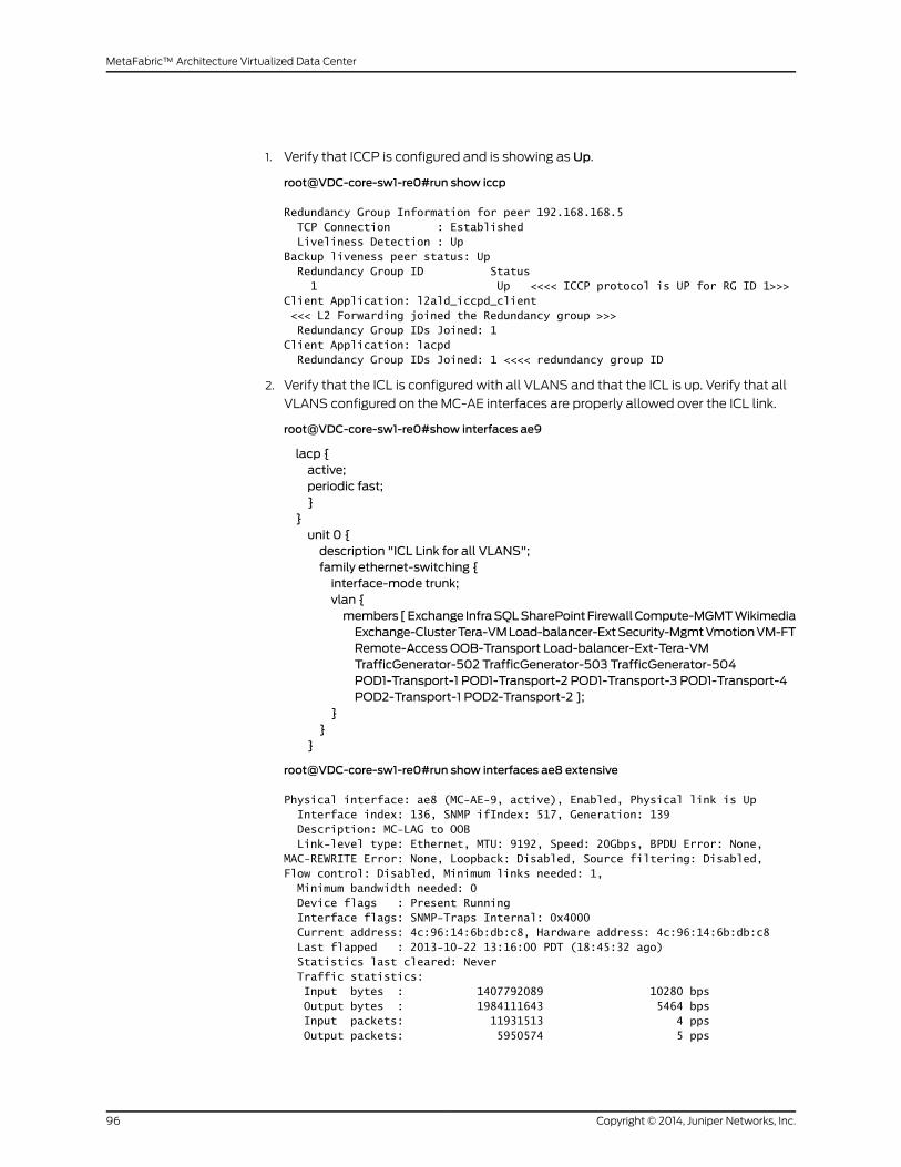
1. Verify that ICCP is configured and is showing as Up.
root@VDC-core-sw1-re0#run show iccp
Redundancy Group Information for peer 192.168.168.5 TCP Connection : Established Liveliness Detection : UpBackup liveness peer status: Up Redundancy Group ID Status 1 Up <<<< ICCP protocol is UP for RG ID 1>>>Client Application: l2ald_iccpd_client <<< L2 Forwarding joined the Redundancy group >>> Redundancy Group IDs Joined: 1 Client Application: lacpd Redundancy Group IDs Joined: 1 <<<< redundancy group ID
2. Verify that the ICL is configured with all VLANS and that the ICL is up. Verify that all
VLANS configured on the MC-AE interfaces are properly allowed over the ICL link.
root@VDC-core-sw1-re0#show interfaces ae9
lacp {active;periodic fast;}
}unit 0 {description "ICL Link for all VLANS";family ethernet-switching {interface-mode trunk;vlan {members[Exchange InfraSQLSharePointFirewallCompute-MGMTWikimediaExchange-ClusterTera-VMLoad-balancer-ExtSecurity-MgmtVmotionVM-FTRemote-Access OOB-Transport Load-balancer-Ext-Tera-VMTrafficGenerator-502 TrafficGenerator-503 TrafficGenerator-504POD1-Transport-1 POD1-Transport-2 POD1-Transport-3 POD1-Transport-4POD2-Transport-1 POD2-Transport-2 ];
}}
}
root@VDC-core-sw1-re0#run show interfaces ae8 extensive
Physical interface: ae8 (MC-AE-9, active), Enabled, Physical link is Up Interface index: 136, SNMP ifIndex: 517, Generation: 139 Description: MC-LAG to OOB Link-level type: Ethernet, MTU: 9192, Speed: 20Gbps, BPDU Error: None, MAC-REWRITE Error: None, Loopback: Disabled, Source filtering: Disabled, Flow control: Disabled, Minimum links needed: 1, Minimum bandwidth needed: 0 Device flags : Present Running Interface flags: SNMP-Traps Internal: 0x4000 Current address: 4c:96:14:6b:db:c8, Hardware address: 4c:96:14:6b:db:c8 Last flapped : 2013-10-22 13:16:00 PDT (18:45:32 ago) Statistics last cleared: Never Traffic statistics: Input bytes : 1407792089 10280 bps Output bytes : 1984111643 5464 bps Input packets: 11931513 4 pps Output packets: 5950574 5 pps
Copyright © 2014, Juniper Networks, Inc.96
MetaFabric™ Architecture Virtualized Data Center

IPv6 transit statistics: Input bytes : 0 Output bytes : 0 Input packets: 0 Output packets: 0 Dropped traffic statistics due to STP State: Input bytes : 0 Output bytes : 0 Input packets: 0 Output packets: 0 Input errors: Errors: 0, Drops: 0, Framing errors: 0, Runts: 0, Giants: 0, Policed discards: 0, Resource errors: 0 Output errors: Carrier transitions: 0, Errors: 0, Drops: 0, MTU errors: 0, Resource errors: 0 Ingress queues: 8 supported, 4 in use Queue counters: Queued packets Transmitted packets Dropped packets 0 best-effort 0 0
0 1 expedited-fo 0 0
0 2 assured-forw 0 0
0 3 network-cont 0 0
0 Egress queues: 8 supported, 4 in use Queue counters: Queued packets Transmitted packets Dropped packets 0 best-effort 5568474 5568474
0 1 expedited-fo 0 0
0 2 assured-forw 0 0
0 3 network-cont 1352698 1352698
0 Queue number: Mapped forwarding classes 0 best-effort 1 expedited-forwarding
2 assured-forwarding 3 network-control
Logical interface ae8.0 (Index 356) (SNMP ifIndex 540) (Generation 165)
Flags: SNMP-Traps 0x24024000 Encapsulation: Ethernet-Bridge Statistics Packets pps Bytes bps Bundle: Input : 11896496 4 1397993319 10280 Output: 5915576 5 1989022843 5160 Link: xe-3/1/0.0
97Copyright © 2014, Juniper Networks, Inc.
Chapter 4: Transport (Routing and Switching) Configuration
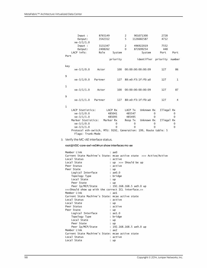
Input : 8765149 2 901071300 2728 Output: 3542312 5 1126682587 4712 xe-3/1/1.0 Input : 3131347 2 496922019 7552 Output: 2408262 0 872699254 448 LACP info: Role System System Port Port Port priority identifier priority number
key xe-3/1/0.0 Actor 100 00:00:00:00:00:09 127 86
9 xe-3/1/0.0 Partner 127 88:e0:f3:1f:f0:a0 127 1
1 xe-3/1/1.0 Actor 100 00:00:00:00:00:09 127 87
9 xe-3/1/1.0 Partner 127 88:e0:f3:1f:f0:a0 127 4
1 LACP Statistics: LACP Rx LACP Tx Unknown Rx Illegal Rx xe-3/1/0.0 485041 485547 0 0 xe-3/1/1.0 485095 485495 0 0 Marker Statistics: Marker Rx Resp Tx Unknown Rx Illegal Rx xe-3/1/0.0 0 0 0 0 xe-3/1/1.0 0 0 0 0 Protocol eth-switch, MTU: 9192, Generation: 199, Route table: 5 Flags: Trunk-Mode
3. Verify the MC-AE interface status.
root@VDC-core-sw1-re0#run show interfacesmc-ae
Member Link : ae0Current State Machine's State: mcae active state >>> Active/ActiveLocal Status : activeLocal State : up >>> Should be upPeer Status : activePeer State : up Logical Interface : ae0.0 Topology Type : bridge Local State : up Peer State : up Peer Ip/MCP/State : 192.168.168.5 ae9.0 up >>>Should show up with the correct ICL interface.>>Member Link : ae1Current State Machine's State: mcae active stateLocal Status : activeLocal State : upPeer Status : activePeer State : up Logical Interface : ae1.0 Topology Type : bridge Local State : up Peer State : up Peer Ip/MCP/State : 192.168.168.5 ae9.0 upMember Link : ae2Current State Machine's State: mcae active stateLocal Status : activeLocal State : up
Copyright © 2014, Juniper Networks, Inc.98
MetaFabric™ Architecture Virtualized Data Center
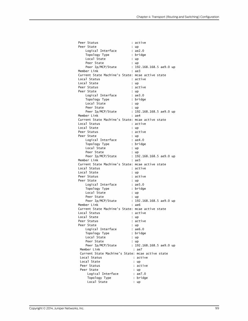
Peer Status : activePeer State : up Logical Interface : ae2.0 Topology Type : bridge Local State : up Peer State : up Peer Ip/MCP/State : 192.168.168.5 ae9.0 upMember Link : ae3Current State Machine's State: mcae active stateLocal Status : activeLocal State : upPeer Status : activePeer State : up Logical Interface : ae3.0 Topology Type : bridge Local State : up Peer State : up Peer Ip/MCP/State : 192.168.168.5 ae9.0 upMember Link : ae4Current State Machine's State: mcae active stateLocal Status : activeLocal State : upPeer Status : activePeer State : up Logical Interface : ae4.0 Topology Type : bridge Local State : up Peer State : up Peer Ip/MCP/State : 192.168.168.5 ae9.0 upMember Link : ae5Current State Machine's State: mcae active stateLocal Status : activeLocal State : upPeer Status : activePeer State : up Logical Interface : ae5.0 Topology Type : bridge Local State : up Peer State : up Peer Ip/MCP/State : 192.168.168.5 ae9.0 upMember Link : ae6Current State Machine's State: mcae active stateLocal Status : activeLocal State : upPeer Status : activePeer State : up Logical Interface : ae6.0 Topology Type : bridge Local State : up Peer State : up Peer Ip/MCP/State : 192.168.168.5 ae9.0 up Member Link : ae7 Current State Machine's State: mcae active state Local Status : active Local State : up Peer Status : active Peer State : up Logical Interface : ae7.0 Topology Type : bridge Local State : up
99Copyright © 2014, Juniper Networks, Inc.
Chapter 4: Transport (Routing and Switching) Configuration

Peer State : up Peer Ip/MCP/State : 192.168.168.5 ae9.0 up Member Link : ae8 Current State Machine's State: mcae active state Local Status : active Local State : up Peer Status : active Peer State : up Logical Interface : ae8.0 Topology Type : bridge Local State : up Peer State : up Peer Ip/MCP/State : 192.168.168.5 ae9.0 up Member Link : ae10 Current State Machine's State: mcae active state Local Status : active Local State : up Peer Status : active Peer State : up Logical Interface : ae10.0 Topology Type : bridge Local State : up Peer State : up Peer Ip/MCP/State : 192.168.168.5 ae9.0 up Member Link : ae11 Current State Machine's State: mcae active state Local Status : active Local State : up Peer Status : active Peer State : up Logical Interface : ae11.0 Topology Type : bridge Local State : up Peer State : up Peer Ip/MCP/State : 192.168.168.5 ae9.0 up Member Link : ae12 Current State Machine's State: mcae active state Local Status : active Local State : up Peer Status : active Peer State : up Logical Interface : ae12.0 Topology Type : bridge Local State : up Peer State : up Peer Ip/MCP/State : 192.168.168.5 ae9.0 up Member Link : ae13 Current State Machine's State: mcae active state Local Status : active Local State : up Peer Status : active Peer State : up Logical Interface : ae13.0 Topology Type : bridge Local State : up Peer State : up Peer Ip/MCP/State : 192.168.168.5 ae9.0 up Member Link : ae14 Current State Machine's State: mcae active state Local Status : active Local State : up
Copyright © 2014, Juniper Networks, Inc.100
MetaFabric™ Architecture Virtualized Data Center

Peer Status : active Peer State : up Logical Interface : ae14.0 Topology Type : bridge Local State : up Peer State : up Peer Ip/MCP/State : 192.168.168.5 ae9.0 up
4. Verify that the ICL and MC-AE interfaces are in the same broadcast domain.
root@VDC-core-sw1-re0#run show vlans POD1-Transport-2
Routing instance VLAN name Tag Interfacesdefault-switch POD1-Transport-2 51 ae1.0* ae9.0*
5. Verify that BFD is configured on all IRB interfaces with an “Up” status. Also verify that
appropriate timers are configured. (A 6-second timer is supported on EX9200 for
MC-LAG Active/Active.)
root@VDC-core-sw1-re0>show bfd session
Detect TransmitAddress State Interface Time Interval Multiplier192.168.2.2 Up ae20.0 6.000 2.000 3
192.168.20.2 Up irb.20 6.000 2.000 3
192.168.20.3 Up irb.20 6.000 2.000 3 192.168.25.2 Up irb.10 6.000 2.000 3 192.168.25.3 Up irb.10 6.000 2.000 3 192.168.50.2 Up irb.50 6.000 2.000 3 192.168.50.3 Up irb.50 6.000 2.000 3 192.168.51.2 Up irb.51 6.000 2.000 3 192.168.51.3 Up irb.51 6.000 2.000 3 192.168.52.2 Up irb.52 6.000 2.000 3 192.168.52.3 Up irb.52 6.000 2.000 3 192.168.53.2 Up irb.53 6.000 2.000 3 192.168.53.3 Up irb.53 6.000 2.000 3 192.168.54.2 Up irb.54 6.000 2.000 3 192.168.54.3 Up irb.54 6.000 2.000 3 192.168.55.2 Up irb.55 6.000 2.000 3 192.168.55.3 Up irb.55 6.000 2.000 3 192.168.168.5 Up 6.000 2.000 3
6. Verify the status of VRRP.
root@VDC-core-sw1-re0>show vrrp summary
Interface State Group VR state VR Mode Type Address irb.10 up 1 backup Active lcl 192.168.25.1
vip 192.168.25.254 irb.15 up 1 backup Active lcl 192.168.15.1
vip 192.168.15.254 irb.16 up 1 backup Active lcl 192.168.16.1
101Copyright © 2014, Juniper Networks, Inc.
Chapter 4: Transport (Routing and Switching) Configuration
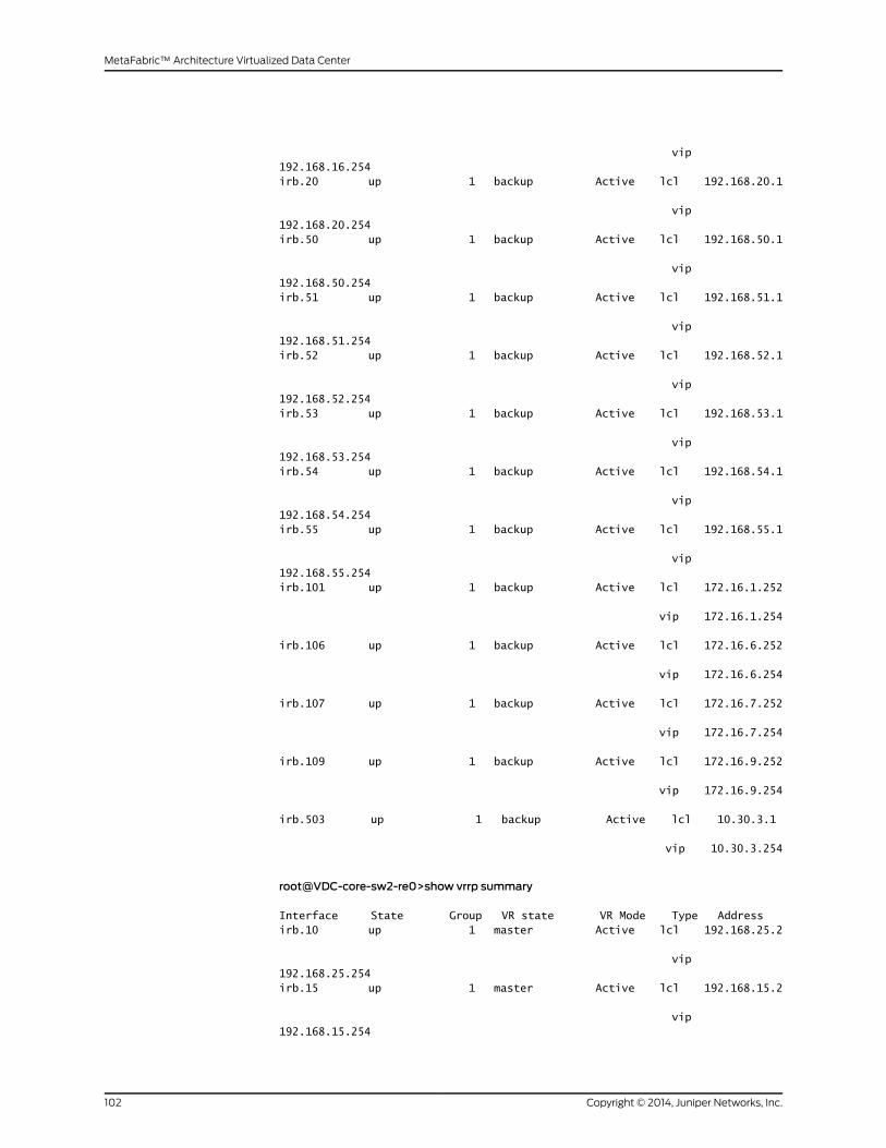
vip 192.168.16.254 irb.20 up 1 backup Active lcl 192.168.20.1
vip 192.168.20.254 irb.50 up 1 backup Active lcl 192.168.50.1
vip 192.168.50.254 irb.51 up 1 backup Active lcl 192.168.51.1
vip 192.168.51.254 irb.52 up 1 backup Active lcl 192.168.52.1
vip 192.168.52.254 irb.53 up 1 backup Active lcl 192.168.53.1
vip 192.168.53.254 irb.54 up 1 backup Active lcl 192.168.54.1
vip 192.168.54.254 irb.55 up 1 backup Active lcl 192.168.55.1
vip 192.168.55.254 irb.101 up 1 backup Active lcl 172.16.1.252
vip 172.16.1.254
irb.106 up 1 backup Active lcl 172.16.6.252
vip 172.16.6.254
irb.107 up 1 backup Active lcl 172.16.7.252
vip 172.16.7.254
irb.109 up 1 backup Active lcl 172.16.9.252
vip 172.16.9.254
irb.503 up 1 backup Active lcl 10.30.3.1
vip 10.30.3.254
root@VDC-core-sw2-re0>show vrrp summary
Interface State Group VR state VR Mode Type Address irb.10 up 1 master Active lcl 192.168.25.2
vip 192.168.25.254 irb.15 up 1 master Active lcl 192.168.15.2
vip 192.168.15.254
Copyright © 2014, Juniper Networks, Inc.102
MetaFabric™ Architecture Virtualized Data Center

irb.16 up 1 master Active lcl 192.168.16.2
vip 192.168.16.254 irb.20 up 1 master Active lcl 192.168.20.2
vip 192.168.20.254 irb.50 up 1 master Active lcl 192.168.50.2
vip 192.168.50.254 irb.51 up 1 master Active lcl 192.168.51.2
vip 192.168.51.254 irb.52 up 1 master Active lcl 192.168.52.2
vip 192.168.52.254 irb.53 up 1 master Active lcl 192.168.53.2
vip 192.168.53.254 irb.54 up 1 master Active lcl 192.168.54.2
vip 192.168.54.254 irb.55 up 1 master Active lcl 192.168.55.2
vip 192.168.55.254 irb.101 up 1 master Active lcl 172.16.1.253
vip 172.16.1.254
irb.106 up 1 master Active lcl 172.16.6.253
vip 172.16.6.254
irb.107 up 1 master Active lcl 172.16.7.253
vip 172.16.7.254
irb.109 up 1 master Active lcl 172.16.9.253
vip 172.16.9.254
irb.503 up 1 master Active lcl 10.30.3.2
vip 10.30.3.254
103Copyright © 2014, Juniper Networks, Inc.
Chapter 4: Transport (Routing and Switching) Configuration
Routing Configuration
• Overview on page 104
• Topology on page 104
• Configuring BGP Between the EDGE and Service Provider on page 106
• Verification on page 108
• Configuring OSPF in the Data Center on page 111
• Verification on page 118
Overview
TheMetaFabric 1.0solution features routingconfiguredbetween theedgeand theservice
provider, as well as routing of traffic from the edge and core roles. BGP is implemented
at the edge. OSPF is used as the IGP in the solution.
Topology
The routing topology and configuration are illustrated in Figure 45 on page 105.
Copyright © 2014, Juniper Networks, Inc.104
MetaFabric™ Architecture Virtualized Data Center

Figure 45: MetaFabric 1.0 Routing Configuration and Topology
The configuration of routing in this solution is outlined in the following sections:
• BGP implementation
• Configuring simulated service provider connectivity
• Configuring VDC-Edge-R1
• Configuring VDC-Edge-R2
• Verifying the configuration
• OSPF implementation
• Configuration overview and parameters
• Link-free alternate overview
105Copyright © 2014, Juniper Networks, Inc.
Chapter 4: Transport (Routing and Switching) Configuration

• Configuration examples
• Verifying the configuration
Configuring BGP Between the EDGE and Service Provider
In VDC 1.0, Internet connectivity for the data center is achieved by establishing EBGP
peering with multiple service providers. As shown in Figure 45 on page 105, EBGP is
configured from Edge-R1 to SP1 and Edge-R2 to SP2. Internet routes are simulated using
testing tools connected to SP1 and SP2. SP1 and SP2 advertise the same Internet routes
to the edge routers.
The next element of routing in the solution is the configuration of EDGE R1 and EDGE R2
peering via iBGP with an export policy to enable "next-hop self". BGP local preference
is configured to prefer the SP1.
• The edge routers must advertise the data center's business-critical applications’
(SharePoint, Exchange, andWikimedia) public address space into the Internet for the
Internet users to access the data center resources. To support redundancy, each edge
router is advertising the same prefix into the Internet.
• Application server Internet access is provided using Source NAT on the edge firewall
and forwarded to the edge routers for Internet access to service provider networks.
• Remote access users connecting from Internetwill use the JunosPulse gateway public
IP address for the VPN connection. The SA appliance VM hosting the pulse gateway
service IP address is advertised to the Internet using an export policy.
To configure BGP between the edge and the service provider, follow these steps:
1. Configure the Simulated Service Provider (1).
a. Configure the AE interface to Edge-R1.
[edit]set interfaces xe-0/0/20 ether-options 802.3ad ae1set interfaces xe-0/0/22 ether-options 802.3ad ae1
set interfaces ae1 description "To VDC Edge R1"set interfaces ae1 aggregated-ether-options lacp activeset interfaces ae1 aggregated-ether-options lacp periodic fastset interfaces ae1 unit 0 family inet address 10.94.127.229/30
b. Configure EBGP peering with Edge-R1.
[edit]set protocols bgp group EDGE-R1 local-address 10.94.127.229set protocols bgp group EDGE-R1 neighbor 10.94.127.230 peer-as 64512
NOTE: Step 1 is provided for completeness. In a real-world scenario, theservice provider configuration is outside of administrator control. Thesolution validation lab simulated a service provider connection as shownin step 1.
Copyright © 2014, Juniper Networks, Inc.106
MetaFabric™ Architecture Virtualized Data Center
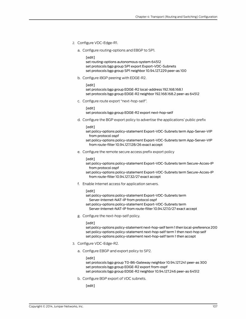
2. Configure VDC-Edge-R1.
a. Configure routing-options and EBGP to SP1.
[edit]set routing-options autonomous-system 64512set protocols bgp group SP1 export Export-VDC-Subnetsset protocols bgp group SP1 neighbor 10.94.127.229 peer-as 100
b. Configure iBGP peering with EDGE-R2.
[edit]set protocols bgp group EDGE-R2 local-address 192.168.168.1set protocols bgp group EDGE-R2 neighbor 192.168.168.2 peer-as 64512
c. Configure route export “next-hop-self”.
[edit]set protocols bgp group EDGE-R2 export next-hop-self
d. Configure the BGP export policy to advertise the applications’ public prefix
[edit]set policy-options policy-statement Export-VDC-Subnets term App-Server-VIPfrom protocol ospf
set policy-options policy-statement Export-VDC-Subnets term App-Server-VIPfrom route-filter 10.94.127.128/26 exact accept
e. Configure the remote secure access prefix export policy
[edit]set policy-options policy-statement Export-VDC-Subnets term Secure-Acces-IPfrom protocol ospf
set policy-options policy-statement Export-VDC-Subnets term Secure-Acces-IPfrom route-filter 10.94.127.32/27 exact accept
f. Enable Internet access for application servers.
[edit]set policy-options policy-statement Export-VDC-Subnets termServer-Internet-NAT-IP from protocol ospf
set policy-options policy-statement Export-VDC-Subnets termServer-Internet-NAT-IP from route-filter 10.94.127.0/27 exact accept
g. Configure the next-hop-self policy.
[edit]set policy-optionspolicy-statement next-hop-self term 1 then local-preference200set policy-options policy-statement next-hop-self term 1 then next-hop selfset policy-options policy-statement next-hop-self term 1 then accept
3. Configure VDC-Edge-R2.
a. Configure EBGP and export policy to SP2.
[edit]set protocols bgp group T0-B6-Gateway neighbor 10.94.127.241 peer-as 300set protocols bgp group EDGE-R2 export from-ospfset protocols bgp group EDGE-R2 neighbor 10.94.127.246 peer-as 64512
b. Configure BGP export of VDC subnets.
[edit]
107Copyright © 2014, Juniper Networks, Inc.
Chapter 4: Transport (Routing and Switching) Configuration

set protocols bgp group SP2 export Export-VDC-Subnetsset protocols bgp group SP2 neighbor 10.94.127.245 peer-as 200
c. Configure iBGP peering with VDC-Edge-R1.
[edit]set protocols bgp group EDGE-R1 local-address 192.168.168.2set protocols bgp group EDGE-R1 export next-hop-selfset protocols bgp group EDGE-R1 neighbor 192.168.168.1 peer-as 64512
d. Configure routing policy.
[edit]set policy-options policy-statement Export-VDC-Subnets term App-Server-VIPfrom protocol ospf
set policy-options policy-statement Export-VDC-Subnets term App-Server-VIPfrom route-filter 10.94.127.128/26 exact accept
set policy-options policy-statement Export-VDC-Subnets term Secure-Acces-IPfrom protocol ospf
set policy-options policy-statement Export-VDC-Subnets term Secure-Acces-IPfrom route-filter 10.94.127.32/27 exact accept
set policy-options policy-statement Export-VDC-Subnets termServer-Internet-NAT-IP from protocol ospf
set policy-options policy-statement Export-VDC-Subnets termServer-Internet-NAT-IP from route-filter 10.94.127.0/27 exact accept
set policy-options policy-statement Export-VDC-Subnets term Tera-VM-Serverfrom route-filter 10.20.127.0/24 exact accept
set policy-options policy-statement Export-VDC-Subnets term TrafficGeneratorfrom protocol ospf
set policy-options policy-statement Export-VDC-Subnets term TrafficGeneratorfrom route-filter 10.30.2.0/24 exact accept
set policy-options policy-statement Export-VDC-Subnets term TrafficGeneratorfrom route-filter 10.30.3.0/24 exact accept
set policy-options policy-statement Export-VDC-Subnets term TrafficGeneratorfrom route-filter 10.30.4.0/24 exact accept
e. Configure BGP “next-hop self”.
[edit]set policy-options policy-statement next-hop-self term 1 from protocol bgpset policy-options policy-statement next-hop-self term 1 then local-preference 100set policy-options policy-statement next-hop-self term 1 then next-hop selfset policy-options policy-statement next-hop-self term 1 then accept
Verification
Purpose The following verification commands (with sample output) can be used to confirm BGP
configuration.
Results
Copyright © 2014, Juniper Networks, Inc.108
MetaFabric™ Architecture Virtualized Data Center

1. Verify on Edge-R1 that an EBGP session with SP1 exists. Also verify the iBGP session
with Edge-R2.
root@VDC-edge-r01-re0>show bgp summary
Groups: 2 Peers: 2 Down peers: 0Table Tot Paths Act Paths Suppressed History Damp State Pendinginet.0 16 7 0 0 0 0Peer AS InPkt OutPkt OutQ Flaps Last Up/Dwn
State|#Active/Received/Accepted/Damped...10.94.127.229 100 46637 46471 0 0 2w0d12h 7/16/16/0 0/0/0/0192.168.168.2 64512 46210 47057 0 0 2w0d12h 0/0/0/0 0/0/0/0
2. Verify on the Edge-R2 that EBGP peering with SP2 and iBGP peering with Edge-R1 is
successful.
root@VDC-edge-r2-re0>show bgp summary
Groups: 2 Peers: 2 Down peers: 0Table Tot Paths Act Paths Suppressed History Damp State Pendinginet.0 75 8 0 0 0 0Peer AS InPkt OutPkt OutQ Flaps Last Up/Dwn
State|#Active/Received/Accepted/Damped...10.94.127.245 200 46378 46671 0 0 2w0d12h 0/16/16/0 0/0/0/0192.168.168.1 64512 47062 46215 0 0 2w0d12h 8/59/59/0 0/0/0/0
3. Verify the routing table on Edge-R1 by showing routes received via BGP.
root@VDC-edge-r01-re0>show route receive-protocol bgp 10.94.127.229
inet.0: 65 destinations, 76 routes (65 active, 0 holddown, 0 hidden) Prefix Nexthop MED Lclpref AS path 0.0.0.0/0 10.94.127.229 100 I* 10.10.0.0/16 10.94.127.229 2 100 I* 10.40.0.0/16 10.94.127.229 2 100 I 10.93.222.0/23 10.94.127.229 100 I 10.94.47.0/27 10.94.127.229 100 I 10.94.63.18/32 10.94.127.229 100 I 10.94.63.19/32 10.94.127.229 100 I* 10.94.127.192/27 10.94.127.229 2 100 I* 10.94.127.224/30 10.94.127.229 100 I 10.94.127.228/30 10.94.127.229 100 I* 10.94.127.240/30 10.94.127.229 2 100 I* 12.12.12.12/32 10.94.127.229 1 100 I 172.17.0.0/16 10.94.127.229 100 I 172.22.0.0/16 10.94.127.229 100 I 172.23.0.0/16 10.94.127.229 100 I* 192.168.253.180/30 10.94.127.229 2 100 I
109Copyright © 2014, Juniper Networks, Inc.
Chapter 4: Transport (Routing and Switching) Configuration
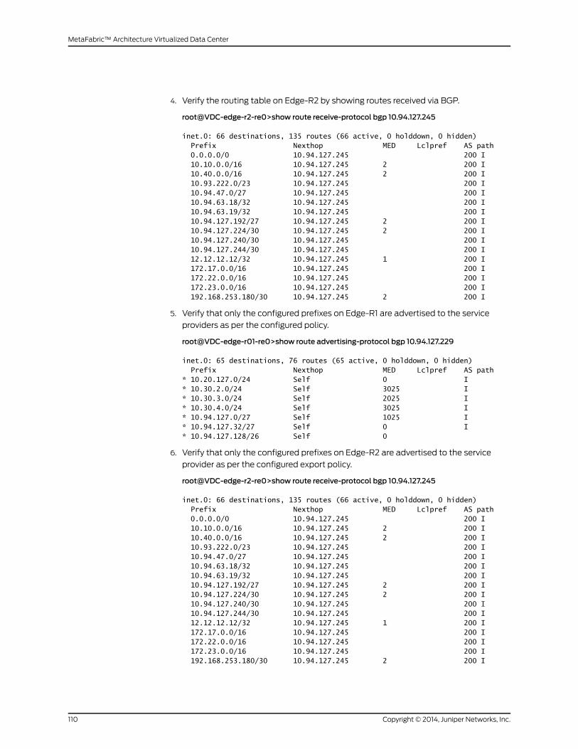
4. Verify the routing table on Edge-R2 by showing routes received via BGP.
root@VDC-edge-r2-re0>show route receive-protocol bgp 10.94.127.245
inet.0: 66 destinations, 135 routes (66 active, 0 holddown, 0 hidden) Prefix Nexthop MED Lclpref AS path 0.0.0.0/0 10.94.127.245 200 I 10.10.0.0/16 10.94.127.245 2 200 I 10.40.0.0/16 10.94.127.245 2 200 I 10.93.222.0/23 10.94.127.245 200 I 10.94.47.0/27 10.94.127.245 200 I 10.94.63.18/32 10.94.127.245 200 I 10.94.63.19/32 10.94.127.245 200 I 10.94.127.192/27 10.94.127.245 2 200 I 10.94.127.224/30 10.94.127.245 2 200 I 10.94.127.240/30 10.94.127.245 200 I 10.94.127.244/30 10.94.127.245 200 I 12.12.12.12/32 10.94.127.245 1 200 I 172.17.0.0/16 10.94.127.245 200 I 172.22.0.0/16 10.94.127.245 200 I 172.23.0.0/16 10.94.127.245 200 I 192.168.253.180/30 10.94.127.245 2 200 I
5. Verify that only the configured prefixes on Edge-R1 are advertised to the service
providers as per the configured policy.
root@VDC-edge-r01-re0>show route advertising-protocol bgp 10.94.127.229
inet.0: 65 destinations, 76 routes (65 active, 0 holddown, 0 hidden) Prefix Nexthop MED Lclpref AS path* 10.20.127.0/24 Self 0 I* 10.30.2.0/24 Self 3025 I* 10.30.3.0/24 Self 2025 I* 10.30.4.0/24 Self 3025 I* 10.94.127.0/27 Self 1025 I* 10.94.127.32/27 Self 0 I* 10.94.127.128/26 Self 0
6. Verify that only the configured prefixes on Edge-R2 are advertised to the service
provider as per the configured export policy.
root@VDC-edge-r2-re0>show route receive-protocol bgp 10.94.127.245
inet.0: 66 destinations, 135 routes (66 active, 0 holddown, 0 hidden) Prefix Nexthop MED Lclpref AS path 0.0.0.0/0 10.94.127.245 200 I 10.10.0.0/16 10.94.127.245 2 200 I 10.40.0.0/16 10.94.127.245 2 200 I 10.93.222.0/23 10.94.127.245 200 I 10.94.47.0/27 10.94.127.245 200 I 10.94.63.18/32 10.94.127.245 200 I 10.94.63.19/32 10.94.127.245 200 I 10.94.127.192/27 10.94.127.245 2 200 I 10.94.127.224/30 10.94.127.245 2 200 I 10.94.127.240/30 10.94.127.245 200 I 10.94.127.244/30 10.94.127.245 200 I 12.12.12.12/32 10.94.127.245 1 200 I 172.17.0.0/16 10.94.127.245 200 I 172.22.0.0/16 10.94.127.245 200 I 172.23.0.0/16 10.94.127.245 200 I 192.168.253.180/30 10.94.127.245 2 200 I
Copyright © 2014, Juniper Networks, Inc.110
MetaFabric™ Architecture Virtualized Data Center
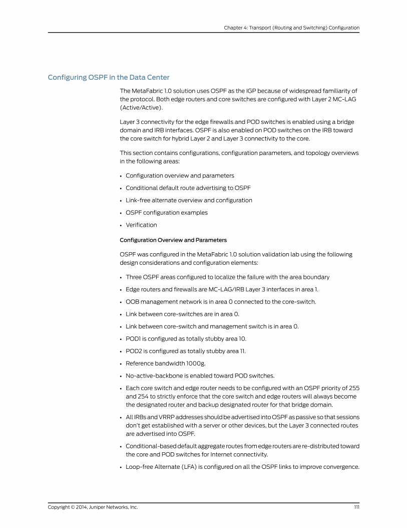
Configuring OSPF in the Data Center
The MetaFabric 1.0 solution uses OSPF as the IGP because of widespread familiarity of
the protocol. Both edge routers and core switches are configured with Layer 2 MC-LAG
(Active/Active).
Layer 3 connectivity for the edge firewalls and POD switches is enabled using a bridge
domain and IRB interfaces. OSPF is also enabled on POD switches on the IRB toward
the core switch for hybrid Layer 2 and Layer 3 connectivity to the core.
This section contains configurations, configuration parameters, and topology overviews
in the following areas:
• Configuration overview and parameters
• Conditional default route advertising to OSPF
• Link-free alternate overview and configuration
• OSPF configuration examples
• Verification
Configuration Overview and Parameters
OSPF was configured in the MetaFabric 1.0 solution validation lab using the following
design considerations and configuration elements:
• Three OSPF areas configured to localize the failure with the area boundary
• Edge routers and firewalls are MC-LAG/IRB Layer 3 interfaces in area 1.
• OOBmanagement network is in area 0 connected to the core-switch.
• Link between core-switches are in area 0.
• Link between core-switch andmanagement switch is in area 0.
• POD1 is configured as totally stubby area 10.
• POD2 is configured as totally stubby area 11.
• Reference bandwidth 1000g.
• No-active-backbone is enabled toward POD switches.
• Each core switch and edge router needs to be configured with an OSPF priority of 255
and 254 to strictly enforce that the core switch and edge routers will always become
the designated router and backup designated router for that bridge domain.
• All IRBsandVRRPaddressesshouldbeadvertised intoOSPFaspassiveso that sessions
don’t get established with a server or other devices, but the Layer 3 connected routes
are advertised into OSPF.
• Conditional-baseddefault aggregate routes fromedge routersare re-distributed toward
the core and POD switches for Internet connectivity.
• Loop-free Alternate (LFA) is configured on all the OSPF links to improve convergence.
111Copyright © 2014, Juniper Networks, Inc.
Chapter 4: Transport (Routing and Switching) Configuration

Figure 46: OSPF Area Configuration Between Edge and Core (IncludingOut-of-BandManagement)
ThePODswitchesareconnected to thecore switchesusingLAG.ThePODsareconfigured
as OSPF areas 10 and 11 (Figure 47 on page 112).
Figure 47: OSPF Area Configuration Between Core and PODs
Configuring Conditional Default Route Advertising to OSPF Based on a Service Provider
Internet Route
In this configuration, if a route exists (the example given is a route to 12.12.12.12), an
aggregate default route (0.0.0.0/0) will be created and exported into OSPF. If the route
to 12.12.12.12 does not exist, due to both SP links being down or the EBGP peering with
the SP being down, the gendefault policy will fail. This policy failure means that the
default aggregate route is not created or exported to OSPF. Configuration of conditional
default route advertising is covered in this section.
Copyright © 2014, Juniper Networks, Inc.112
MetaFabric™ Architecture Virtualized Data Center

To configure conditional route advertising to OSPF based on the presence of a service
provider Internet route, follow these steps:
1. On the edge routers, check to verify that the route to 12.12.12.12 has been learned via
EBGP(fromanyserviceprovider using thepolicy). Createagendefault policymatching
a route from SP 12.12.12.12.
[edit]set policy-options policy-statement gendefault term upstreamroutes from route-filter12.12.12.12/32 exact
set policy-options policy-statement gendefault term upstreamroutes from protocolbgp
set policy-options policy-statement gendefault term upstreamroutes then acceptset policy-options policy-statement gendefault term deny then reject
2. If the policy matches, then an aggregate default route will be created.
[edit]set routing-options generate route 0.0.0.0/0 policy gendefault
3. Create a routing policy to export the aggregated route into OSPF.
[edit]setpolicy-optionspolicy-statementexport-default-route term1 fromprotocolaggregateset policy-options policy-statement export-default-route term 1 from route-filter0.0.0.0/0 exact
set policy-options policy-statement export-default-route term 1 then external type 1set policy-options policy-statement export-default-route term 1 then accept
4. Apply the policy to OSPF.
[edit]set protocols ospf export export-default-route
Configuring Loop-Free Alternate
Loop-free alternate (LFA) is a mechanism used to pre-calculate the loop-free backup
paths and program the forwarding table to quickly use in case of failure for a given prefix.
The IGP SPF database is used to calculate the LFA route. After a failure is detected using
BFD or OAM, the PFE-complex signals the failure up to the control plane, where the
routingdaemon (RPD) resides. Pleasenote that at this stage, theonly thing that is known
is a failed link. Once this happens, the router now has two tasks:
• Calculating a shortest path to the destination and choosing a next hop to circumvent
the failed link. Typically a link-state protocol is being used as IGP, such as OSPF and
IS-IS. Both protocols will have to perform a Dijkstra-algorithm to calculate a loop-free
topology again. This is known as shortest-path first (SPF) calculation.
• Informing theneighbors of this link failure toallowother routers calculatinganupdated
loop-free topology as well.
AfterRPDcalculatesall newnexthops forall givenprefixes, this newnext-hop information
needs to be pushed down to the Packet Forwarding Engine. Once the Packet Forwarding
Engine is updated, traffic is reroutedand flowsagain. At this stage, local-repair is achieved,
as this node has done all calculations and rerouting. Other nodes in the network might
not yet have received the updates regarding the link failure. Once all nodes in the network
113Copyright © 2014, Juniper Networks, Inc.
Chapter 4: Transport (Routing and Switching) Configuration
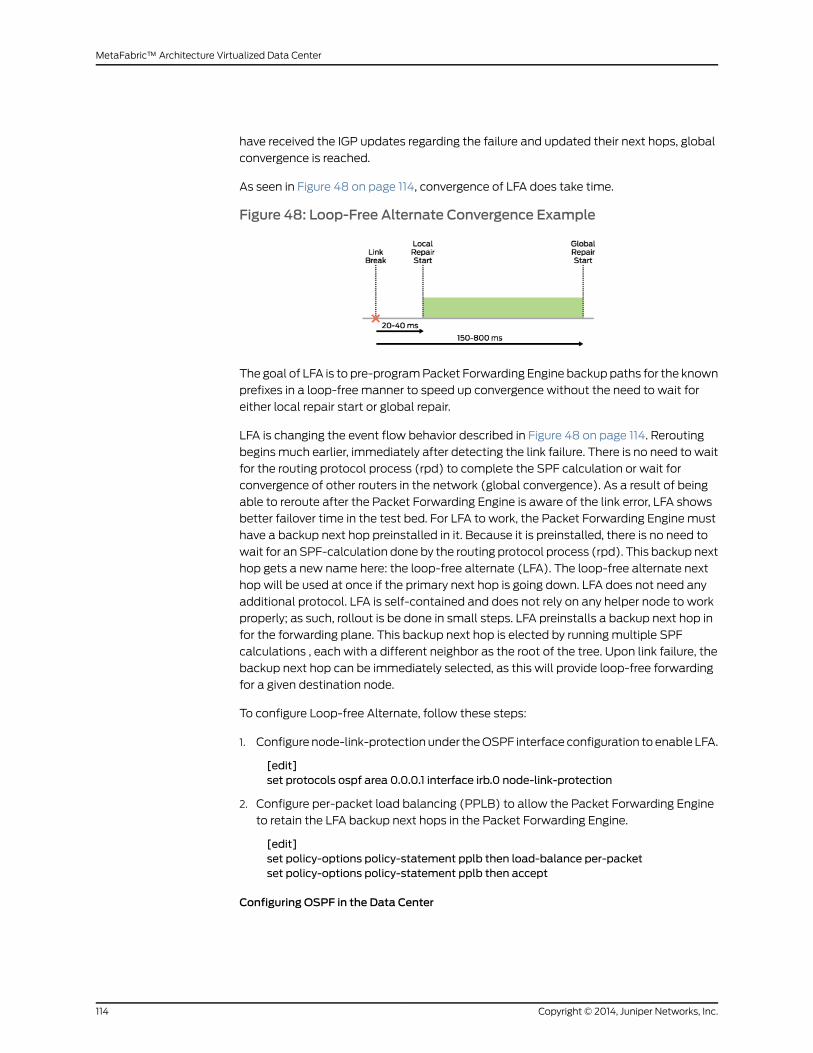
have received the IGP updates regarding the failure and updated their next hops, global
convergence is reached.
As seen in Figure 48 on page 114, convergence of LFA does take time.
Figure 48: Loop-Free Alternate Convergence Example
The goal of LFA is to pre-programPacket Forwarding Engine backup paths for the known
prefixes in a loop-free manner to speed up convergence without the need to wait for
either local repair start or global repair.
LFA is changing the event flow behavior described in Figure 48 on page 114. Rerouting
beginsmuch earlier, immediately after detecting the link failure. There is no need to wait
for the routing protocol process (rpd) to complete the SPF calculation or wait for
convergence of other routers in the network (global convergence). As a result of being
able to reroute after the Packet Forwarding Engine is aware of the link error, LFA shows
better failover time in the test bed. For LFA to work, the Packet Forwarding Engine must
have a backup next hop preinstalled in it. Because it is preinstalled, there is no need to
wait for an SPF-calculation done by the routing protocol process (rpd). This backup next
hop gets a new name here: the loop-free alternate (LFA). The loop-free alternate next
hop will be used at once if the primary next hop is going down. LFA does not need any
additional protocol. LFA is self-contained and does not rely on any helper node to work
properly; as such, rollout is be done in small steps. LFA preinstalls a backup next hop in
for the forwarding plane. This backup next hop is elected by running multiple SPF
calculations , each with a different neighbor as the root of the tree. Upon link failure, the
backup next hop can be immediately selected, as this will provide loop-free forwarding
for a given destination node.
To configure Loop-free Alternate, follow these steps:
1. Configure node-link-protection under theOSPF interface configuration to enable LFA.
[edit]set protocols ospf area 0.0.0.1 interface irb.0 node-link-protection
2. Configure per-packet load balancing (PPLB) to allow the Packet Forwarding Engine
to retain the LFA backup next hops in the Packet Forwarding Engine.
[edit]set policy-options policy-statement pplb then load-balance per-packetset policy-options policy-statement pplb then accept
Configuring OSPF in the Data Center
Copyright © 2014, Juniper Networks, Inc.114
MetaFabric™ Architecture Virtualized Data Center

OSPF configuration in the data center is covered in the following section. The following
nodes and solution elements are configured below:
• Edge router configuration
• Firewall configuration
• Core switch configuration
• POD switch configuration
115Copyright © 2014, Juniper Networks, Inc.
Chapter 4: Transport (Routing and Switching) Configuration

To configure OSPF in the data center, follow these steps:
1. Configure the edge router.
a. Configure and apply export policy, SPF reference bandwidth, LFA, and priority.
[edit]set protocols ospf export export-default-routeset protocols ospf reference-bandwidth 1000gset protocols ospf area 0.0.0.1 interface irb.0 node-link-protectionset protocols ospf area 0.0.0.1 interface irb.0 priority 254
b. Enable BFD protection on the IRB.
[edit]set protocols ospf area 0.0.0.1 interface irb.0 bfd-liveness-detectionminimum-interval 500
set protocols ospf area 0.0.0.1 interface ae0.0 node-link-protectionset protocols ospf area 0.0.0.1 interface ae0.0 priority 254set protocols ospf area 0.0.0.1 interface ae0.0 bfd-liveness-detectionminimum-interval 500
set protocols ospf area 0.0.0.1 interface ae0.0 bfd-liveness-detectionmultiplier 2set protocols ospf area 0.0.0.1 interface lo0.0
c. Configure the condition policy for the OSPF default route based on the BGP route.
[edit]set policy-options policy-statement export-default-route term 1 from protocolaggregate
set policy-options policy-statement export-default-route term 1 from route-filter0.0.0.0/0 exact
set policy-options policy-statement export-default-route term 1 then external type1
set policy-options policy-statement export-default-route term 1 then acceptset policy-optionspolicy-statement gendefault termupstreamroutes fromprotocolbgp
setpolicy-optionspolicy-statementgendefault termupstreamroutesfromroute-filter12.12.12.12/32 exact
set policy-options policy-statement gendefault term upstreamroutes then acceptset policy-options policy-statement gendefault term deny then rejectset routing-options generate route 0.0.0.0/0 policy gendefault
d. Configure PPLB.
[edit]set policy-options policy-statement pplb then load-balance per-packetset policy-options policy-statement pplb then acceptset routing-options forwarding-table export pplb
2. Configure OSPF and BFD on the firewalls.
[edit]set protocols ospf export OSPF-Export-SAset protocols ospf reference-bandwidth 1000gset protocols ospf area 0.0.0.1 interface reth1.0 node-link-protectionsetprotocolsospfarea0.0.0.1 interface reth1.0bfd-liveness-detectionminimum-interval500
set protocols ospf area 0.0.0.1 interface reth1.0 bfd-liveness-detectionmultiplier 2set protocols ospf area 0.0.0.1 interface reth0.0 node-link-protection
Copyright © 2014, Juniper Networks, Inc.116
MetaFabric™ Architecture Virtualized Data Center
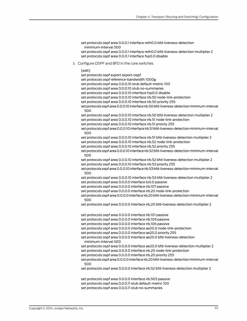
set protocols ospf area 0.0.0.1 interface reth0.0 bfd-liveness-detectionminimum-interval 500
set protocols ospf area 0.0.0.1 interface reth0.0 bfd-liveness-detectionmultiplier 2set protocols ospf area 0.0.0.1 interface fxp0.0 disable
3. Configure OSPF and BFD in the core switches
[edit]set protocols ospf export export-ospfset protocols ospf reference-bandwidth 1000gset protocols ospf area 0.0.0.10 stub default-metric 100set protocols ospf area 0.0.0.10 stub no-summariesset protocols ospf area 0.0.0.10 interface fxp0.0 disableset protocols ospf area 0.0.0.10 interface irb.50 node-link-protectionset protocols ospf area 0.0.0.10 interface irb.50 priority 255setprotocolsospfarea0.0.0.10 interface irb.50bfd-liveness-detectionminimum-interval500
set protocols ospf area 0.0.0.10 interface irb.50 bfd-liveness-detectionmultiplier 2set protocols ospf area 0.0.0.10 interface irb.51 node-link-protectionset protocols ospf area 0.0.0.10 interface irb.51 priority 255setprotocolsospfarea0.0.0.10 interface irb.51bfd-liveness-detectionminimum-interval500
set protocols ospf area 0.0.0.10 interface irb.51 bfd-liveness-detectionmultiplier 2set protocols ospf area 0.0.0.10 interface irb.52 node-link-protectionset protocols ospf area 0.0.0.10 interface irb.52 priority 255setprotocolsospfarea0.0.0.10 interface irb.52bfd-liveness-detectionminimum-interval500
set protocols ospf area 0.0.0.10 interface irb.52 bfd-liveness-detectionmultiplier 2set protocols ospf area 0.0.0.10 interface irb.53 priority 255setprotocolsospfarea0.0.0.10 interface irb.53bfd-liveness-detectionminimum-interval500
set protocols ospf area 0.0.0.10 interface irb.53 bfd-liveness-detectionmultiplier 2set protocols ospf area 0.0.0.0 interface lo0.0 passiveset protocols ospf area 0.0.0.0 interface irb.107 passiveset protocols ospf area 0.0.0.0 interface irb.20 node-link-protectionsetprotocolsospfarea0.0.0.0 interface irb.20bfd-liveness-detectionminimum-interval500
set protocols ospf area 0.0.0.0 interface irb.20 bfd-liveness-detectionmultiplier 2
set protocols ospf area 0.0.0.0 interface irb.101 passiveset protocols ospf area 0.0.0.0 interface irb.109 passiveset protocols ospf area 0.0.0.0 interface irb.106 passiveset protocols ospf area 0.0.0.0 interface ae20.0 node-link-protectionset protocols ospf area 0.0.0.0 interface ae20.0 priority 255set protocols ospf area 0.0.0.0 interface ae20.0 bfd-liveness-detectionminimum-interval 500
set protocols ospf area 0.0.0.0 interface ae20.0 bfd-liveness-detectionmultiplier 2set protocols ospf area 0.0.0.0 interface irb.20 node-link-protectionset protocols ospf area 0.0.0.0 interface irb.20 priority 255setprotocolsospfarea0.0.0.0 interface irb.20bfd-liveness-detectionminimum-interval500
set protocols ospf area 0.0.0.0 interface irb.52 bfd-liveness-detectionmultiplier 2
set protocols ospf area 0.0.0.0 interface irb.503 passiveset protocols ospf area 0.0.0.11 stub default-metric 100set protocols ospf area 0.0.0.11 stub no-summaries
117Copyright © 2014, Juniper Networks, Inc.
Chapter 4: Transport (Routing and Switching) Configuration

set protocols ospf area 0.0.0.11 interface irb.54 node-link-protectionset protocols ospf area 0.0.0.11 interface irb.54 priority 255setprotocolsospfarea0.0.0.11 interface irb.54bfd-liveness-detectionminimum-interval500
set protocols ospf area 0.0.0.11 interface irb.54 bfd-liveness-detectionmultiplier 2set protocols ospf area 0.0.0.11 interface irb.55 node-link-protectionset protocols ospf area 0.0.0.11 interface irb.55 priority 255setprotocolsospfarea0.0.0.11 interface irb.55bfd-liveness-detectionminimum-interval500
set protocols ospf area 0.0.0.11 interface irb.55 bfd-liveness-detectionmultiplier 2set protocols ospf area 0.0.0.1 interface irb.10 node-link-protectionset protocols ospf area 0.0.0.1 interface irb.10 priority 255setprotocolsospfarea0.0.0.1 interface irb.10bfd-liveness-detectionminimum-interval500
set protocols ospf area 0.0.0.1 interface irb.52 bfd-liveness-detectionmultiplier 2set protocols ospf area 0.0.0.1 interface irb.14 node-link-protectionset protocols ospf area 0.0.0.1 interface irb.14 passiveset protocols ospf area 0.0.0.1 interface irb.14 priority 255set protocols ospf area 0.0.0.1 interface irb.15 node-link-protectionset protocols ospf area 0.0.0.1 interface irb.15 passiveset protocols ospf area 0.0.0.1 interface irb.15 priority 255
4. Configure OSPF in the PODs.
[edit]set protocols ospf reference-bandwidth 1000gset protocols ospf area 0.0.0.10 stub no-summariesset protocols ospf area 0.0.0.10 interface vlan.104 passiveset protocols ospf area 0.0.0.10 interface vlan.108 passiveset protocols ospf area 0.0.0.10 interface vlan.103 passiveset protocols ospf area 0.0.0.10 interface vlan.502 passiveset protocols ospf area 0.0.0.10 interface vlan.503set protocols ospf area 0.0.0.10 interface vlan.50 node-link-protectionset protocols ospf area 0.0.0.10 interface vlan.50 bfd-liveness-detectionminimum-interval 500
set protocols ospf area 0.0.0.10 interface vlan.50 bfd-liveness-detectionmultiplier 2set protocols ospf area 0.0.0.10 interface vlan.51 node-link-protectionset protocols ospf area 0.0.0.10 interface vlan.51 bfd-liveness-detectionminimum-interval 500
set protocols ospf area 0.0.0.10 interface vlan.51 bfd-liveness-detectionmultiplier 2set protocols ospf area 0.0.0.10 interface vlan.52 node-link-protectionset protocols ospf area 0.0.0.10 interface vlan.52 bfd-liveness-detectionminimum-interval 500
set protocols ospf area 0.0.0.10 interface vlan.52 bfd-liveness-detectionmultiplier 2set protocols ospf area 0.0.0.10 interface vlan.53 node-link-protectionset protocols ospf area 0.0.0.10 interface vlan.53 bfd-liveness-detectionminimum-interval 500
set protocols ospf area 0.0.0.10 interface vlan.53 bfd-liveness-detectionmultiplier 2set protocols ospf area 0.0.0.10 interface vlan.501 passive
Verification
Purpose The following verificationcommands (with sampleoutput) canbeused toconfirmOSPF
configuration in the data center.
Results
Copyright © 2014, Juniper Networks, Inc.118
MetaFabric™ Architecture Virtualized Data Center

1. Verify that all OSPF sessions are up (command outputs provided for all configured
routers).
root@VDC-edge-r01-re0>show ospf neighbor
Address Interface State ID Pri Dead192.168.1.2 ae0.0 Full 192.168.168.2 254 38192.168.26.3 irb.0 Full 192.168.168.3 128 39192.168.26.2 irb.0 Full 192.168.168.2 254 37
root@VDC-edge-r2-re0>show ospf neighbor
Address Interface State ID Pri Dead192.168.1.1 ae0.0 Full 192.168.168.1 254 35192.168.26.3 irb.0 Full 192.168.168.3 128 34192.168.26.1 irb.0 Full 192.168.168.1 254 39
root@VDC-edge-fw01-n1>show ospf neighbor
Address Interface State ID Pri Dead192.168.25.2 reth0.0 Full 192.168.168.5 255 34192.168.25.1 reth0.0 Full 192.168.168.4 255 35192.168.26.2 reth1.0 Full 192.168.168.2 254 35192.168.26.1 reth1.0 Full 192.168.168.1 254 36
root@VDC-core-sw1-re0>show ospf neighbor
Address Interface State ID Pri Dead192.168.2.2 ae20.0 Full 192.168.168.5 255 33192.168.25.2 irb.10 Full 192.168.168.5 255 39192.168.25.3 irb.10 Full 192.168.168.3 128 39192.168.50.2 irb.50 Full 192.168.168.5 255 35192.168.50.3 irb.50 Full 192.168.168.6 128 37192.168.51.2 irb.51 Full 192.168.168.5 255 36192.168.51.3 irb.51 Full 192.168.168.6 128 35192.168.52.2 irb.52 Full 192.168.168.5 255 38192.168.52.3 irb.52 Full 192.168.168.6 128 31192.168.53.2 irb.53 Full 192.168.168.5 255 37192.168.53.3 irb.53 Full 192.168.168.6 128 33192.168.54.2 irb.54 Full 192.168.168.5 255 34192.168.54.3 irb.54 Full 192.168.168.7 128 36192.168.55.2 irb.55 Full 192.168.168.5 255 33192.168.55.3 irb.55 Full 192.168.168.7 128 35192.168.20.2 irb.20 Full 192.168.168.5 255 39192.168.20.3 irb.20 Full 192.168.168.20 128 39
root@VDC-core-sw2-re0>show ospf neighbor
Address Interface State ID Pri Dead192.168.2.1 ae20.0 Full 192.168.168.4 255 38192.168.25.1 irb.10 Full 192.168.168.4 255 32192.168.25.3 irb.10 Full 192.168.168.3 128 31192.168.50.3 irb.50 Full 192.168.168.6 128 38192.168.50.1 irb.50 Full 192.168.168.4 255 34192.168.51.1 irb.51 Full 192.168.168.4 255 39192.168.51.3 irb.51 Full 192.168.168.6 128 37192.168.52.1 irb.52 Full 192.168.168.4 255 35192.168.52.3 irb.52 Full 192.168.168.6 128 33192.168.53.1 irb.53 Full 192.168.168.4 255 39192.168.53.3 irb.53 Full 192.168.168.6 128 34192.168.54.1 irb.54 Full 192.168.168.4 255 35192.168.54.3 irb.54 Full 192.168.168.7 128 38
119Copyright © 2014, Juniper Networks, Inc.
Chapter 4: Transport (Routing and Switching) Configuration
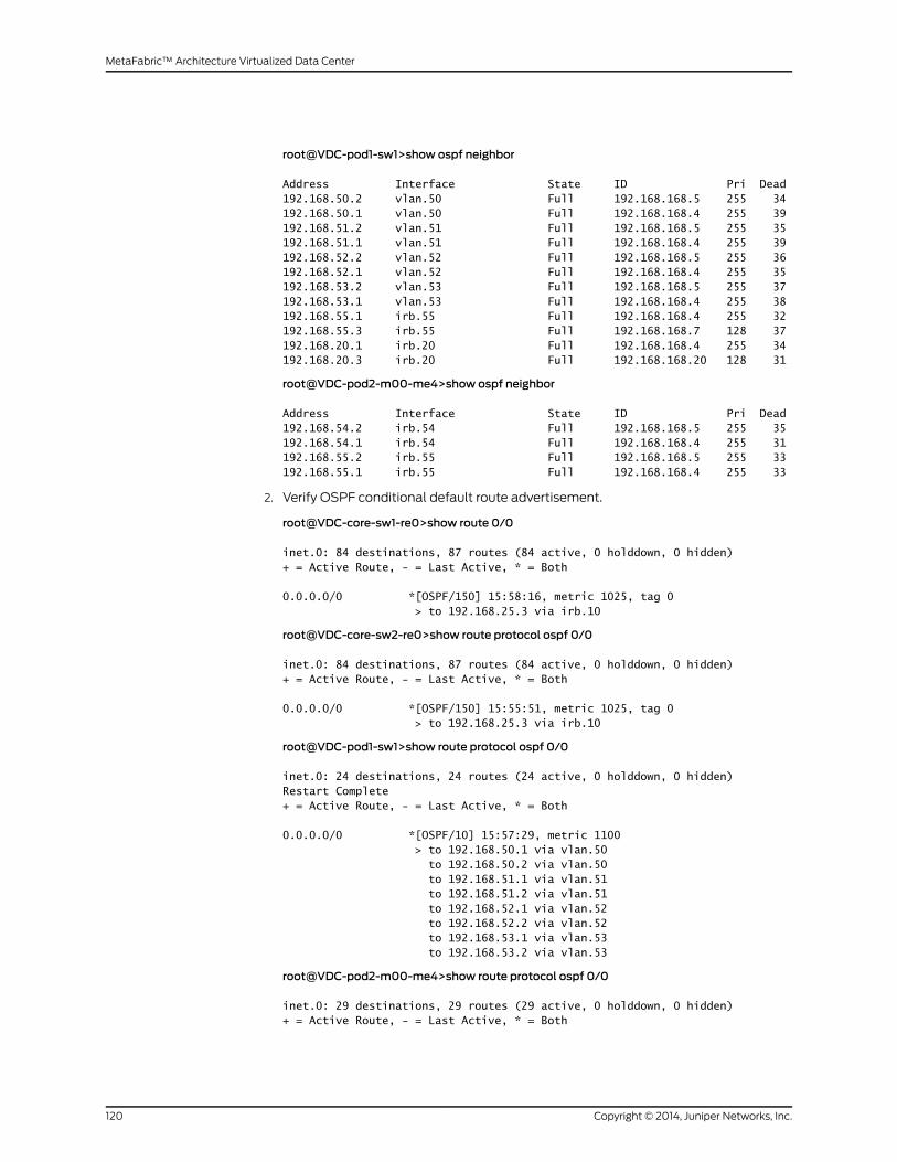
root@VDC-pod1-sw1>show ospf neighbor
Address Interface State ID Pri Dead192.168.50.2 vlan.50 Full 192.168.168.5 255 34192.168.50.1 vlan.50 Full 192.168.168.4 255 39192.168.51.2 vlan.51 Full 192.168.168.5 255 35192.168.51.1 vlan.51 Full 192.168.168.4 255 39192.168.52.2 vlan.52 Full 192.168.168.5 255 36192.168.52.1 vlan.52 Full 192.168.168.4 255 35192.168.53.2 vlan.53 Full 192.168.168.5 255 37192.168.53.1 vlan.53 Full 192.168.168.4 255 38192.168.55.1 irb.55 Full 192.168.168.4 255 32192.168.55.3 irb.55 Full 192.168.168.7 128 37192.168.20.1 irb.20 Full 192.168.168.4 255 34192.168.20.3 irb.20 Full 192.168.168.20 128 31
root@VDC-pod2-m00-me4>show ospf neighbor
Address Interface State ID Pri Dead192.168.54.2 irb.54 Full 192.168.168.5 255 35192.168.54.1 irb.54 Full 192.168.168.4 255 31192.168.55.2 irb.55 Full 192.168.168.5 255 33192.168.55.1 irb.55 Full 192.168.168.4 255 33
2. Verify OSPF conditional default route advertisement.
root@VDC-core-sw1-re0>show route 0/0
inet.0: 84 destinations, 87 routes (84 active, 0 holddown, 0 hidden)+ = Active Route, - = Last Active, * = Both
0.0.0.0/0 *[OSPF/150] 15:58:16, metric 1025, tag 0 > to 192.168.25.3 via irb.10
root@VDC-core-sw2-re0>show route protocol ospf 0/0
inet.0: 84 destinations, 87 routes (84 active, 0 holddown, 0 hidden)+ = Active Route, - = Last Active, * = Both
0.0.0.0/0 *[OSPF/150] 15:55:51, metric 1025, tag 0 > to 192.168.25.3 via irb.10
root@VDC-pod1-sw1>show route protocol ospf 0/0
inet.0: 24 destinations, 24 routes (24 active, 0 holddown, 0 hidden)Restart Complete+ = Active Route, - = Last Active, * = Both
0.0.0.0/0 *[OSPF/10] 15:57:29, metric 1100 > to 192.168.50.1 via vlan.50 to 192.168.50.2 via vlan.50 to 192.168.51.1 via vlan.51 to 192.168.51.2 via vlan.51 to 192.168.52.1 via vlan.52 to 192.168.52.2 via vlan.52 to 192.168.53.1 via vlan.53 to 192.168.53.2 via vlan.53
root@VDC-pod2-m00-me4>show route protocol ospf 0/0
inet.0: 29 destinations, 29 routes (29 active, 0 holddown, 0 hidden)+ = Active Route, - = Last Active, * = Both
Copyright © 2014, Juniper Networks, Inc.120
MetaFabric™ Architecture Virtualized Data Center

0.0.0.0/0 *[OSPF/10] 15:57:30, metric 1100 to 192.168.54.1 via irb.54 > to 192.168.54.2 via irb.54 to 192.168.55.1 via irb.55 to 192.168.55.2 via irb.55
3. Verify OSPF LFA routes.
root@VDC-edge-r01-re0>show ospf backup coverage
Topology default coverage:
Node Coverage:
Area Covered Total Percent Nodes Nodes Covered0.0.0.1 2 4 50.00%
Route Coverage:
Path Type Covered Total Percent Routes Routes CoveredIntra 4 7 57.14%Inter 0 32 0.00%Ext1 1 1 100.00%Ext2 1 3 33.33%All 6 43 13.95%
root@VDC-edge-r2-re0%cli
{master}
root@VDC-edge-r2-re0>show ospf backup coverage
Topology default coverage:
Node Coverage:
Area Covered Total Percent Nodes Nodes Covered0.0.0.1 1 4 25.00%
Route Coverage:
Path Type Covered Total Percent Routes Routes CoveredIntra 2 7 28.57%Inter 0 32 0.00%Ext1 1 1 100.00%Ext2 0 3 0.00%All 3 43 6.98%
root@VDC-core-sw1-re0>show ospf backup coverage
Topology default coverage:
Node Coverage:
Area Covered Total Percent Nodes Nodes Covered0.0.0.0 0 1 0.00%0.0.0.1 0 4 0.00%0.0.0.10 2 2 100.00%
121Copyright © 2014, Juniper Networks, Inc.
Chapter 4: Transport (Routing and Switching) Configuration
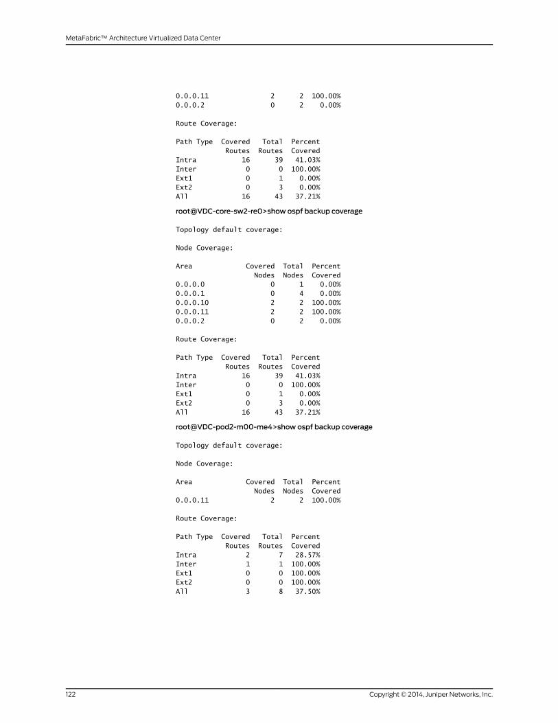
0.0.0.11 2 2 100.00%0.0.0.2 0 2 0.00%
Route Coverage:
Path Type Covered Total Percent Routes Routes CoveredIntra 16 39 41.03%Inter 0 0 100.00%Ext1 0 1 0.00%Ext2 0 3 0.00%All 16 43 37.21%
root@VDC-core-sw2-re0>show ospf backup coverage
Topology default coverage:
Node Coverage:
Area Covered Total Percent Nodes Nodes Covered0.0.0.0 0 1 0.00%0.0.0.1 0 4 0.00%0.0.0.10 2 2 100.00%0.0.0.11 2 2 100.00%0.0.0.2 0 2 0.00%
Route Coverage:
Path Type Covered Total Percent Routes Routes CoveredIntra 16 39 41.03%Inter 0 0 100.00%Ext1 0 1 0.00%Ext2 0 3 0.00%All 16 43 37.21%
root@VDC-pod2-m00-me4>show ospf backup coverage
Topology default coverage:
Node Coverage:
Area Covered Total Percent Nodes Nodes Covered0.0.0.11 2 2 100.00%
Route Coverage:
Path Type Covered Total Percent Routes Routes CoveredIntra 2 7 28.57%Inter 1 1 100.00%Ext1 0 0 100.00%Ext2 0 0 100.00%All 3 8 37.50%
Copyright © 2014, Juniper Networks, Inc.122
MetaFabric™ Architecture Virtualized Data Center
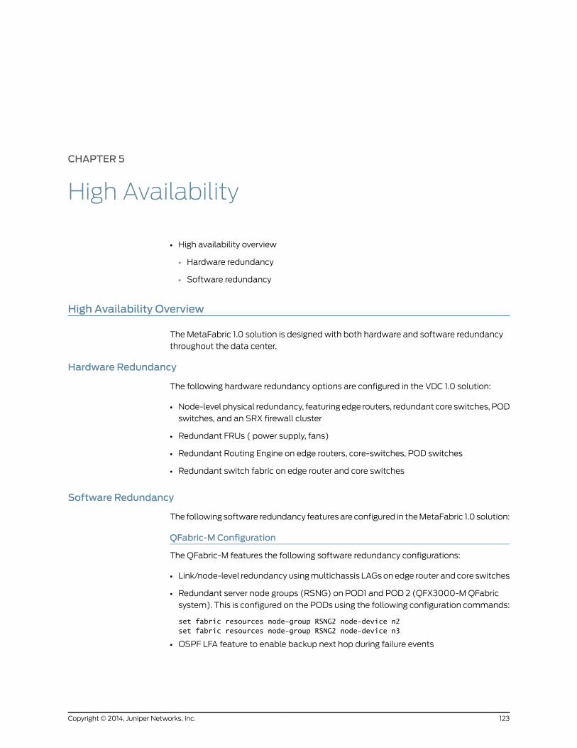
CHAPTER 5
High Availability
• High availability overview
• Hardware redundancy
• Software redundancy
High Availability Overview
The MetaFabric 1.0 solution is designed with both hardware and software redundancy
throughout the data center.
Hardware Redundancy
The following hardware redundancy options are configured in the VDC 1.0 solution:
• Node-level physical redundancy, featuringedge routers, redundant core switches, POD
switches, and an SRX firewall cluster
• Redundant FRUs ( power supply, fans)
• Redundant Routing Engine on edge routers, core-switches, POD switches
• Redundant switch fabric on edge router and core switches
Software Redundancy
The following software redundancy featuresare configured in theMetaFabric 1.0 solution:
QFabric-M Configuration
The QFabric-M features the following software redundancy configurations:
• Link/node-level redundancy usingmultichassis LAGsonedge router and core switches
• Redundant server node groups (RSNG) on POD1 and POD 2 (QFX3000-MQFabric
system). This is configured on the PODs using the following configuration commands:
set fabric resources node-group RSNG2 node-device n2set fabric resources node-group RSNG2 node-device n3
• OSPF LFA feature to enable backup next hop during failure events
123Copyright © 2014, Juniper Networks, Inc.
• QFX3000-MQFabric system built-in architecture supports hardware and software
redundancy
• Non-step software upgrade (NSSU) is supported on theQFX3000-MQFabric system
• Protocol graceful restart is configured using the following command:
set groups global routing-options graceful-restart
NOTE: WhenNSR is enabled, graceful protocol restart is not supported.NSRis not currently supported on the QFX3000-MQFabric system.
Configurint the Core and Edge Router
The core switches (EX9200) and edge routers (MX240) feature software redundancy
configured as shown here:
• Graceful Routing Engine switchover (GRES) on Routing Engine hardware failure. This
is configured on MX Series platforms using the following commands:
set groups global chassis redundancy routing-engine 0 masterset groups global chassis redundancy routing-engine 1 backupset groups global chassis redundancy failover on-loss-of-keepalivesset groups global chassis redundancy graceful-switchover
• Nonstop software upgrade (NSSU) is supported on the QFX3000-MQFabric system
and MX240
• In-service software upgrade (ISSU) is supported (EX9200)
NOTE: ISSU is supported only with the presence of 1-Gbps line cardsavailable in the chassis (EX9200).
• Nonstop active routing (NSR) is supported. This is configured using the following
command:
set groups global routing-options nonstop-routing
NOTE: When NSR is enabled, graceful protocol restart is not supported.NSR is not supported on the QFX3000-MQFabric system.
• Nonstop bridging (NSB) is enabled using the following command:
set protocols layer2-control nonstop-bridging
Copyright © 2014, Juniper Networks, Inc.124
MetaFabric™ Architecture Virtualized Data Center
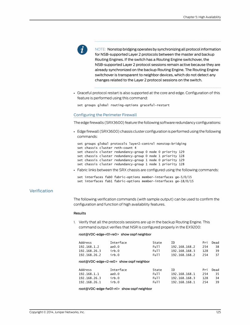
NOTE: Nonstopbridgingoperatesbysynchronizingallprotocol informationfor NSB-supported Layer 2 protocols between themaster and backupRouting Engines. If the switch has a Routing Engine switchover, theNSB-supported Layer 2 protocol sessions remain active because they arealready synchronized on the backup Routing Engine. The Routing Engineswitchover is transparent to neighbor devices, which do not detect anychanges related to the Layer 2 protocol sessions on the switch.
• Graceful protocol restart is also supported at the core and edge. Configuration of this
feature is performed using this command:
set groups global routing-options graceful-restart
Configuring the Perimeter Firewall
Theedge firewalls (SRX3600) feature the following software redundancyconfigurations:
• Edge firewall (SRX3600)chassis cluster configuration is performedusing the following
commands:
set groups global protocols layer2-control nonstop-bridgingset chassis cluster reth-count 4set chassis cluster redundancy-group 0 node 0 priority 129set chassis cluster redundancy-group 0 node 1 priority 128set chassis cluster redundancy-group 1 node 0 priority 129set chassis cluster redundancy-group 1 node 1 priority 128
• Fabric links between the SRX chassis are configured using the following commands:
set interfaces fab0 fabric-options member-interfaces ge-5/0/15set interfaces fab1 fabric-options member-interfaces ge-18/0/15
Verification
The following verification commands (with sample output) can be used to confirm the
configuration and function of high availability features.
Results
1. Verify that all the protocols sessions are up in the backup Routing Engine. This
command output verifies that NSR is configured properly in the EX9200:
root@VDC-edge-r01-re0> show ospf neighbor
Address Interface State ID Pri Dead192.168.1.2 ae0.0 Full 192.168.168.2 254 38192.168.26.3 irb.0 Full 192.168.168.3 128 39192.168.26.2 irb.0 Full 192.168.168.2 254 37
root@VDC-edge-r2-re0> show ospf neighbor
Address Interface State ID Pri Dead192.168.1.1 ae0.0 Full 192.168.168.1 254 35192.168.26.3 irb.0 Full 192.168.168.3 128 34192.168.26.1 irb.0 Full 192.168.168.1 254 39
root@VDC-edge-fw01-n1> show ospf neighbor
125Copyright © 2014, Juniper Networks, Inc.
Chapter 5: High Availability
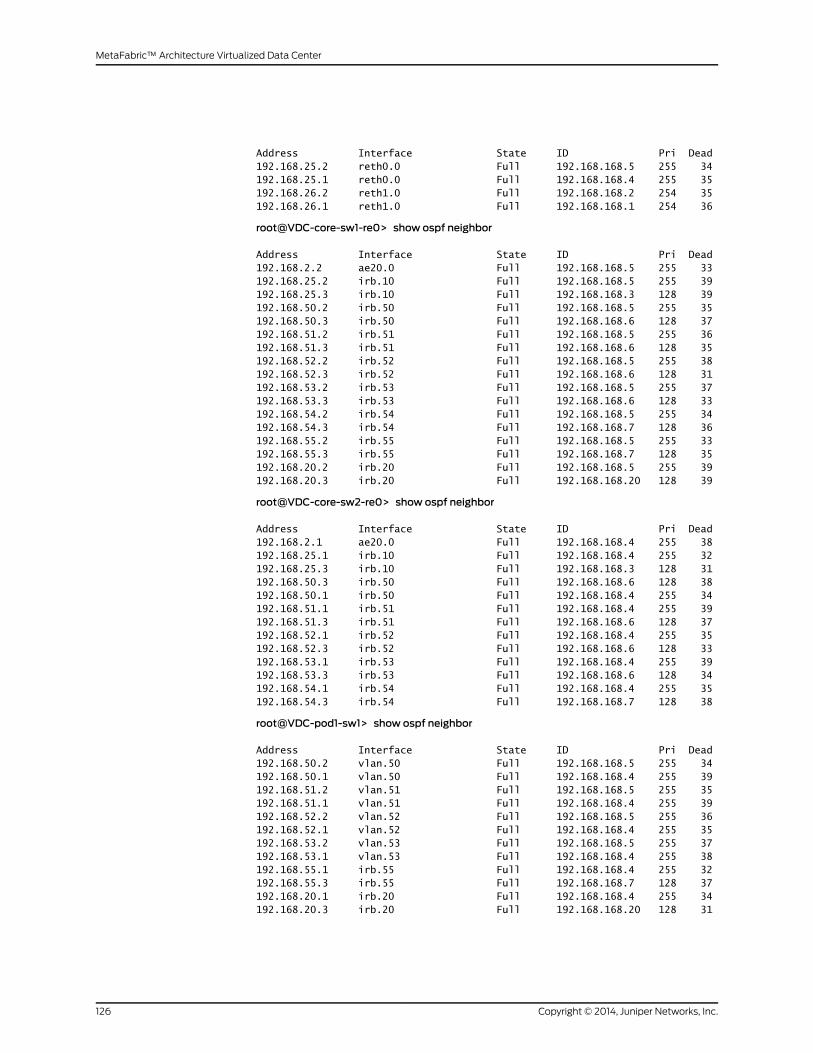
Address Interface State ID Pri Dead192.168.25.2 reth0.0 Full 192.168.168.5 255 34192.168.25.1 reth0.0 Full 192.168.168.4 255 35192.168.26.2 reth1.0 Full 192.168.168.2 254 35192.168.26.1 reth1.0 Full 192.168.168.1 254 36
root@VDC-core-sw1-re0> show ospf neighbor
Address Interface State ID Pri Dead192.168.2.2 ae20.0 Full 192.168.168.5 255 33192.168.25.2 irb.10 Full 192.168.168.5 255 39192.168.25.3 irb.10 Full 192.168.168.3 128 39192.168.50.2 irb.50 Full 192.168.168.5 255 35192.168.50.3 irb.50 Full 192.168.168.6 128 37192.168.51.2 irb.51 Full 192.168.168.5 255 36192.168.51.3 irb.51 Full 192.168.168.6 128 35192.168.52.2 irb.52 Full 192.168.168.5 255 38192.168.52.3 irb.52 Full 192.168.168.6 128 31192.168.53.2 irb.53 Full 192.168.168.5 255 37192.168.53.3 irb.53 Full 192.168.168.6 128 33192.168.54.2 irb.54 Full 192.168.168.5 255 34192.168.54.3 irb.54 Full 192.168.168.7 128 36192.168.55.2 irb.55 Full 192.168.168.5 255 33192.168.55.3 irb.55 Full 192.168.168.7 128 35192.168.20.2 irb.20 Full 192.168.168.5 255 39192.168.20.3 irb.20 Full 192.168.168.20 128 39
root@VDC-core-sw2-re0> show ospf neighbor
Address Interface State ID Pri Dead192.168.2.1 ae20.0 Full 192.168.168.4 255 38192.168.25.1 irb.10 Full 192.168.168.4 255 32192.168.25.3 irb.10 Full 192.168.168.3 128 31192.168.50.3 irb.50 Full 192.168.168.6 128 38192.168.50.1 irb.50 Full 192.168.168.4 255 34192.168.51.1 irb.51 Full 192.168.168.4 255 39192.168.51.3 irb.51 Full 192.168.168.6 128 37192.168.52.1 irb.52 Full 192.168.168.4 255 35192.168.52.3 irb.52 Full 192.168.168.6 128 33192.168.53.1 irb.53 Full 192.168.168.4 255 39192.168.53.3 irb.53 Full 192.168.168.6 128 34192.168.54.1 irb.54 Full 192.168.168.4 255 35192.168.54.3 irb.54 Full 192.168.168.7 128 38
root@VDC-pod1-sw1> show ospf neighbor
Address Interface State ID Pri Dead192.168.50.2 vlan.50 Full 192.168.168.5 255 34192.168.50.1 vlan.50 Full 192.168.168.4 255 39192.168.51.2 vlan.51 Full 192.168.168.5 255 35192.168.51.1 vlan.51 Full 192.168.168.4 255 39192.168.52.2 vlan.52 Full 192.168.168.5 255 36192.168.52.1 vlan.52 Full 192.168.168.4 255 35192.168.53.2 vlan.53 Full 192.168.168.5 255 37192.168.53.1 vlan.53 Full 192.168.168.4 255 38192.168.55.1 irb.55 Full 192.168.168.4 255 32192.168.55.3 irb.55 Full 192.168.168.7 128 37192.168.20.1 irb.20 Full 192.168.168.4 255 34192.168.20.3 irb.20 Full 192.168.168.20 128 31
Copyright © 2014, Juniper Networks, Inc.126
MetaFabric™ Architecture Virtualized Data Center
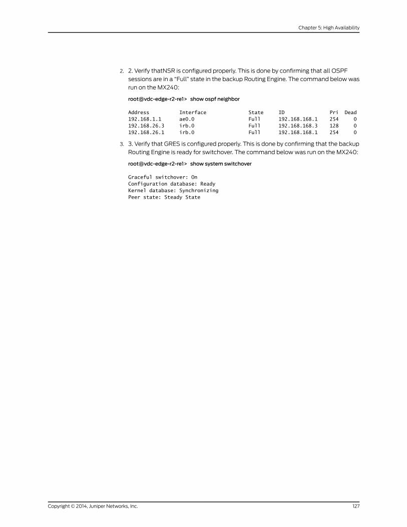
2. 2. Verify thatNSR is configured properly. This is done by confirming that all OSPF
sessions are in a “Full” state in the backup Routing Engine. The command belowwas
run on the MX240:
root@vdc-edge-r2-re1> show ospf neighbor
Address Interface State ID Pri Dead192.168.1.1 ae0.0 Full 192.168.168.1 254 0192.168.26.3 irb.0 Full 192.168.168.3 128 0192.168.26.1 irb.0 Full 192.168.168.1 254 0
3. 3. Verify that GRES is configured properly. This is done by confirming that the backup
Routing Engine is ready for switchover. The command belowwas run on the MX240:
root@vdc-edge-r2-re1> show system switchover
Graceful switchover: OnConfiguration database: ReadyKernel database: SynchronizingPeer state: Steady State
127Copyright © 2014, Juniper Networks, Inc.
Chapter 5: High Availability

Copyright © 2014, Juniper Networks, Inc.128
MetaFabric™ Architecture Virtualized Data Center

CHAPTER 6
Class-of-Service Configuration
The following section covers class-of-service (CoS) configuration in the MetaFabric 1.0
solution. The CoS configuration covers the following areas:
• Class-of-service overview
• Class- of-service configuration in the PODs
• Class- of-service configuration
• Data Center Bridging (DCB) and lossless Ethernet configuration
• Verification
• Class-of-Service Overview on page 129
• Configuring Class-of-Service on page 130
• Configuring Data Center Bridging and Lossless Ethernet on page 130
Class-of-Service Overview
Requirements
End-to-end class of service is required in a data center environment to ensure a high
quality user experience for users of business-critical applications. Themost important
or high priority applications and services should always have priority over other traffic
types. The other type of class of service required is configuration and support for DCB
and the provisioning of Lossless Ethernet to enable communication between storage
arrays as a high priority, lossless mediumwithout causing blocking or interruption of
non-storage traffic.
End-to-end traffic and CoS in this solution have been classified into the following five
forwarding classes (sorted from highest priority to lowest priority, top to bottom):
• Network control traffic
• Virtualization control
• Storage (Llossless)
• Business applications
• Best effort (everything else)
129Copyright © 2014, Juniper Networks, Inc.

The solution queues (buffers and transmit rates) are shown in Table 18 on page 130.
Table 18: MetaFabric 1.0 Class-of-Service Queues
QueueLoss PriorityTransmit RateSchedulers
111High5%Network-control
110High5%VM_Control
001High25%Business_Applications
100Low (PFC enabled)60%no-loss
000High5%Best-effort.
Configuring Class-of-Service
This section covers the configuration of the following solution components:
• Class of service in the Points of Delivery (PODs).
• DCB in the PODs
• Lossless Ethernet configuration
Configuring Class-of-Service (POD Level)
Configuration of the solution starts with the configuration of the perimeter security;
integration between the edge, perimeter, and the data center core; and then continues
with configuration of the access and aggregation roles in the data center (in this solution,
those roles are collapsed into theQFabric POD). Finally, the networkmust be configured
in the virtual switching role.
Configuring Data Center Bridging and Lossless Ethernet
This section covers the configuration of the following solution components:
• Class of service in the PODs
• Data center bridging (DCB¬) in the PODs
• Lossless Ethernet configuration
Configuring Class-of-Service (POD Level)
Configuration of the solution starts with the configuration of the perimeter security;
integration between the edge, perimeter, and the data center core; and then continues
with configuration of the access and aggregation roles in the data center (these roles
are collapsed into the QFabric POD in the MetaFabric 1.0 solution). Finally, the network
must be configured in the virtual switching role.
Copyright © 2014, Juniper Networks, Inc.130
MetaFabric™ Architecture Virtualized Data Center
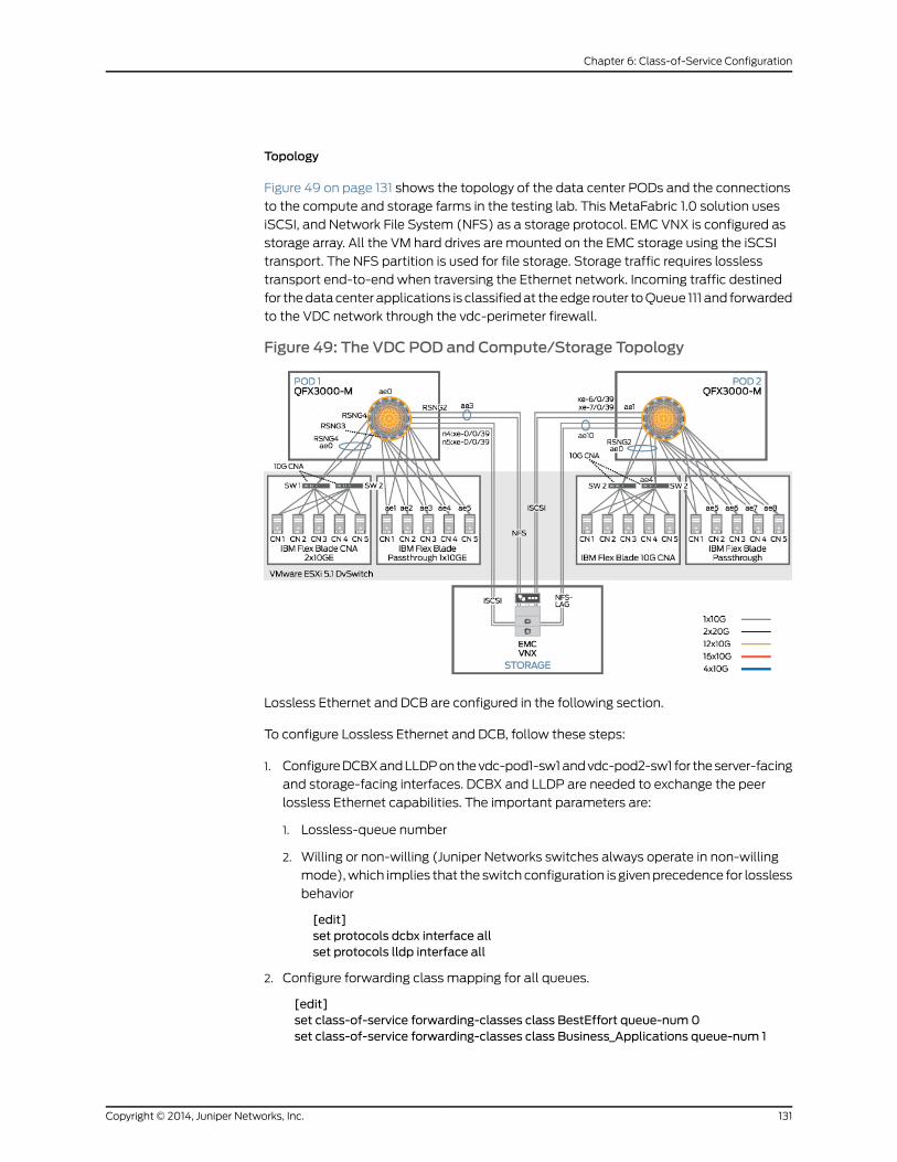
Topology
Figure 49 on page 131 shows the topology of the data center PODs and the connections
to the compute and storage farms in the testing lab. This MetaFabric 1.0 solution uses
iSCSI, and Network File System (NFS) as a storage protocol. EMC VNX is configured as
storage array. All the VM hard drives are mounted on the EMC storage using the iSCSI
transport. The NFS partition is used for file storage. Storage traffic requires lossless
transport end-to-end when traversing the Ethernet network. Incoming traffic destined
for thedatacenter applications is classifiedat theedge router toQueue 111 and forwarded
to the VDC network through the vdc-perimeter firewall.
Figure 49: The VDC POD and Compute/Storage Topology
Lossless Ethernet and DCB are configured in the following section.
To configure Lossless Ethernet and DCB, follow these steps:
1. ConfigureDCBXandLLDPonthevdc-pod1-sw1andvdc-pod2-sw1 for theserver-facing
and storage-facing interfaces. DCBX and LLDP are needed to exchange the peer
lossless Ethernet capabilities. The important parameters are:
1. Lossless-queue number
2. Willing or non-willing (Juniper Networks switches always operate in non-willing
mode),which implies that the switch configuration is givenprecedence for lossless
behavior
[edit]set protocols dcbx interface allset protocols lldp interface all
2. Configure forwarding class mapping for all queues.
[edit]set class-of-service forwarding-classes class BestEffort queue-num0set class-of-service forwarding-classes class Business_Applications queue-num 1
131Copyright © 2014, Juniper Networks, Inc.
Chapter 6: Class-of-Service Configuration

set class-of-service forwarding-classes class no-loss queue-num 4set class-of-service forwarding-classes class no-loss no-lossset class-of-service forwarding-classes class VM_Control queue-num 6set class-of-service forwarding-classes class Network_Control queue-num 7
3. Configure 802.1p classifiers for the iSCSi traffic and assign code-points as 4.
[edit]set class-of-service classifiers ieee-802.1 802.1-classifier forwarding-class BestEffortloss-priority low code-points 000
set class-of-service classifiers ieee-802.1 802.1-classifier forwarding-classBusiness_Applications loss-priority low code-points 001
set class-of-service classifiers ieee-802.1 802.1-classifier forwarding-class VM_Controlloss-priority low code-points 110
set class-of-service classifiers ieee-802.1 802.1-classifier forwarding-class no-lossloss-priority low code-points 100
set class-of-service classifiers ieee-802.1 802.1-classifier forwarding-classNetwork_Control loss-priority low code-points 111
set class-of-service host-outbound-traffic forwarding-class Network_Control
4. Configure forwarding class-sets for iSCSI and Ethernet traffic (representing different
forwarding classes).
[edit]set class-of-service forwarding-class-sets no-loss class no-lossset class-of-service forwarding-class-sets VDC-Lan class BestEffortset class-of-service forwarding-class-sets VDC-Lan class Business_Applicationsset class-of-service forwarding-class-sets VDC-Lan class Network_Controlset class-of-service forwarding-class-sets VDC-Lan class VM_Control
5. Configure thecongestionnotificationprofile toenablePFCforqueue3(no-lossqueue).
This configuration ismandatory, enabling lossless behavior on queue 3. This enforces
priority-flow-control for the queue.
[edit]set class-of-service congestion-notification-profile cnp input ieee-802.1 code-point100 pfc
6. 6. Configure the transmit rate and priority for each scheduler to allow for bandwidth
sharing.
[edit] set class-of-service schedulers BestEffort transmit-rate percent 5set class-of-service schedulers BestEffort priority lowset class-of-service schedulers Business_Applications transmit-rate percent 25set class-of-service schedulers Business_Applications priority lowset class-of-service schedulers VM_Control transmit-rate percent 5set class-of-service schedulers VM_Control priority lowset class-of-service schedulers no-loss transmit-rate percent 60set class-of-service schedulers no-loss priority lowset class-of-service schedulers Network_Control transmit-rate percent 5set class-of-service schedulers Network_Control priority low
7. Configure scheulder-maps for iSCSI. This configuration binds the scheduler to the
forwarding class sets.
[edit]set class-of-service scheduler-maps VDC-Lan forwarding-class BestEffort schedulerBestEffort
set class-of-servicescheduler-mapsVDC-Lan forwarding-classBusiness_Applications
Copyright © 2014, Juniper Networks, Inc.132
MetaFabric™ Architecture Virtualized Data Center
scheduler Business_Applicationsset class-of-service scheduler-maps VDC-Lan forwarding-class VM_Control schedulerVM_Control
set class-of-service scheduler-maps VDC-Lan forwarding-class Network_Controlscheduler Network_Control
setclass-of-servicescheduler-mapsno-loss forwarding-classno-lossschedulerno-loss
8. Configure traffic control profiles. These profiles bind the scheduler maps.
[edit]set class-of-service traffic-control-profiles no-loss scheduler-map no-lossset class-of-service traffic-control-profiles no-loss guaranteed-rate percent 60set class-of-service traffic-control-profiles VDC-Lan scheduler-map VDC-Lanset class-of-service traffic-control-profiles VDC-Lan guaranteed-rate percent 40
9. 9. Apply the classifier, forwarding class set, and CNP profile to the server-facing and
storage-facing interfaces. In the verification lab, these ports are all facing
TrafficGenerator test equipment.
a. Configure the server-connected ports.
[edit]set class-of-service interfaces RSNG2:ae0 forwarding-class-set no-lossoutput-traffic-control-profile no-loss
set class-of-service interfaces RSNG2:ae0 forwarding-class-set VDC-Lanoutput-traffic-control-profile VDC-Lan
set class-of-service interfaces RSNG2:ae0 congestion-notification-profile cnpsetclass-of-service interfacesRSNG2:ae0unit*classifiers ieee-802.1802.1-classifierset class-of-service interfaces RSNG2:ae0 unit * rewrite-rules ieee-802.1802.1-rewrite
b. Configure the storage-connected ports.
[edit]set class-of-service interfaces n1:xe-0/0/14 forwarding-class-set VDC-Lanoutput-traffic-control-profile VDC-Lan
set class-of-service interfaces n1:xe-0/0/14 forwarding-class-set no-lossoutput-traffic-control-profile no-loss
set class-of-service interfaces n1:xe-0/0/14 congestion-notification-profile cnpset class-of-service interfaces n1:xe-0/0/14 unit * classifiers ieee-802.1802.1-classifier
set class-of-service interfaces n1:xe-0/0/15 forwarding-class-set VDC-Lanoutput-traffic-control-profile VDC-Lan
set class-of-service interfaces n1:xe-0/0/15 forwarding-class-set no-lossoutput-traffic-control-profile no-loss
set class-of-service interfaces n1:xe-0/0/15 congestion-notification-profile cnpset class-of-service interfaces n1:xe-0/0/15 unit * classifiers ieee-802.1802.1-classifier
set class-of-service interfaces n1:xe-0/0/16 forwarding-class-set VDC-Lanoutput-traffic-control-profile VDC-Lan
set class-of-service interfaces n1:xe-0/0/16 forwarding-class-set no-lossoutput-traffic-control-profile no-loss
set class-of-service interfaces n1:xe-0/0/16 congestion-notification-profile cnpset class-of-service interfaces n1:xe-0/0/16 unit * classifiers ieee-802.1802.1-classifier
set class-of-service interfaces n1:xe-0/0/16 unit * rewrite-rules ieee-802.1802.1-rewrite
133Copyright © 2014, Juniper Networks, Inc.
Chapter 6: Class-of-Service Configuration
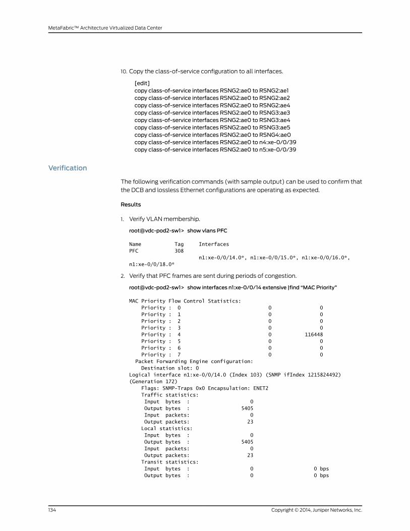
10. Copy the class-of-service configuration to all interfaces.
[edit]copy class-of-service interfaces RSNG2:ae0 to RSNG2:ae1copy class-of-service interfaces RSNG2:ae0 to RSNG2:ae2copy class-of-service interfaces RSNG2:ae0 to RSNG2:ae4copy class-of-service interfaces RSNG2:ae0 to RSNG3:ae3copy class-of-service interfaces RSNG2:ae0 to RSNG3:ae4copy class-of-service interfaces RSNG2:ae0 to RSNG3:ae5copy class-of-service interfaces RSNG2:ae0 to RSNG4:ae0copy class-of-service interfaces RSNG2:ae0 to n4:xe-0/0/39copy class-of-service interfaces RSNG2:ae0 to n5:xe-0/0/39
Verification
The following verification commands (with sample output) can be used to confirm that
the DCB and lossless Ethernet configurations are operating as expected.
Results
1. Verify VLANmembership.
root@vdc-pod2-sw1> show vlans PFC
Name Tag InterfacesPFC 308 n1:xe-0/0/14.0*, n1:xe-0/0/15.0*, n1:xe-0/0/16.0*, n1:xe-0/0/18.0*
2. Verify that PFC frames are sent during periods of congestion.
root@vdc-pod2-sw1> show interfaces n1:xe-0/0/14 extensive |find “MAC Priority”
MAC Priority Flow Control Statistics: Priority : 0 0 0 Priority : 1 0 0 Priority : 2 0 0 Priority : 3 0 0 Priority : 4 0 116448 Priority : 5 0 0 Priority : 6 0 0 Priority : 7 0 0 Packet Forwarding Engine configuration: Destination slot: 0Logical interface n1:xe-0/0/14.0 (Index 103) (SNMP ifIndex 1215824492) (Generation 172) Flags: SNMP-Traps 0x0 Encapsulation: ENET2 Traffic statistics: Input bytes : 0 Output bytes : 5405 Input packets: 0 Output packets: 23 Local statistics: Input bytes : 0 Output bytes : 5405 Input packets: 0 Output packets: 23 Transit statistics: Input bytes : 0 0 bps Output bytes : 0 0 bps
Copyright © 2014, Juniper Networks, Inc.134
MetaFabric™ Architecture Virtualized Data Center

Input packets: 0 0 pps Output packets: 0 0 pps Protocol eth-switch, MTU: 9192, Generation: 200, Route table: 0 Flags: Trunk-Mode
3. Verify that packets in other queues are dropped during congestion. Also verify that
queue 4 (lossless queue) is showing no drops.
root@pod2-sw1> show interfaces queue n1:xe-0/0/16
Physical interface: xe-0/0/16, Enabled, Physical link is Up Interface index: 49199, SNMP ifIndex: 1215824460Forwarding classes: 16 supported, 7 in useEgress queues: 12 supported, 7 in use
Queue: 0, Forwarding classes: BestEffort
Queued: Packets : 0 0 pps Bytes : 0 0 bps Transmitted: Packets : 17848847 422311 pps Bytes : 2284652416 432446792 bps Tail-dropped packets : Not Available Total-dropped packets: 71401120 1689149 pps Total-dropped bytes : 9139343360 1729689096 bps
Queue: 1, Forwarding classes: Business_Applications
Queued: Packets : 0 0 pps Bytes : 0 0 bps Transmitted: Packets : 89238496 2111415 pps Bytes : 11422527488 2162089504 bps Tail-dropped packets : Not Available Total-dropped packets: 0 0 pps Total-dropped bytes : 0 0 bps
Queue: 3, Forwarding classes: fcoe
Queued: Packets : 0 0 pps Bytes : 0 0 bps Transmitted: Packets : 0 0 pps Bytes : 0 0 bps Tail-dropped packets : Not Available Total-dropped packets: 0 0 pps Total-dropped bytes : 0 0 bps
Queue: 4, Forwarding classes: no-loss
Queued: Packets : 0 0 pps Bytes : 0 0 bps Transmitted: Packets : 8700524783 5067522 pps Bytes : 1113667172224 5189143528 bps Tail-dropped packets : Not Available Total-dropped packets: 0 0 pps Total-dropped bytes : 0 0 bps
135Copyright © 2014, Juniper Networks, Inc.
Chapter 6: Class-of-Service Configuration

Queue: 6, Forwarding classes: VM_Control
Queued: Packets : 0 0 pps Bytes : 0 0 bps Transmitted: Packets : 17848844 422310 pps Bytes : 2284652032 432446128 bps Tail-dropped packets : Not Available Total-dropped packets: 71401096 1689144 pps Total-dropped bytes : 9139340288 1729683800 bps
Queue: 7, Forwarding classes: Network_Control
Queued: Packets : 0 0 pps Bytes : 0 0 bps Transmitted: Packets : 17849477 422311 pps Bytes : 2284699608 432446792 bps Tail-dropped packets : Not Available Total-dropped packets: 71401145 1689147 pps Total-dropped bytes : 9139345327 1729686776 bps
Queue: 8, Forwarding classes: mcastQueued: Packets : 0 0 pps Bytes : 0 0 bps Transmitted: Packets : 0 0 pps Bytes : 0 0 bps Tail-dropped packets : Not Available Total-dropped packets: 0 0 pps Total-dropped bytes : 0 0 bps
Copyright © 2014, Juniper Networks, Inc.136
MetaFabric™ Architecture Virtualized Data Center
CHAPTER 7
Security Configuration
This section covers the configuration of security in the MetaFabric 1.0 solution. The
operational roles covered by this section are:
• Perimeter security
• Configure chassis clustering
• Control and data fabric configuratio
• Node-specific configuration
• Security configuration (zones, address books, policies)
• Network Address Translation (NAT)
• Intrusion detection and prevention (IDP)
• • Host security
• Application security (Virtual Gateway Appliance)
• Perimeter Security on page 137
• Host Security on page 155
Perimeter Security
• Overview on page 137
• Verification on page 144
• Configuring Network Address Translation on page 144
• Verification on page 146
• Configuring Intrusion Detection and Prevention on page 148
• Verification on page 153
Overview
The Juniper Networks SRX3600 is deployed in this solution as the edge firewall and
provides perimeter security for the virtualized data center network residing between the
edge router andcore switch. TheSRX3600 is configured in active/backupchassis cluster
mode.Active/backuphighavailability is themost commontypeofhighavailability firewall
137Copyright © 2014, Juniper Networks, Inc.

deployment and consists of two firewall members of a cluster, one of which actively
provides routing, firewall, NAT, VPN, and security services, alongwithmaintaining control
of the chassis cluster. In case of chassis cluster failover, the backup firewall will become
the active firewall and the active firewall will become the backup.
Configuring Chassis Clustering
Configuring chassis cluster requires a minimum of two devices. Here, we are using
SRX3600, which has similar hardware and Junos OS software version. Since we only
have a single cluster, the solution uses only cluster-id 1 SRX 3600-1 acting as node 0.
SRX 3600-2 is configured as node 1. These commands are the only commands where it
matters which chassis member you apply them to because the setting is stored in the
NVRAM rather than in the configuration itself. The command will also cause the cluster
member to reboot, which is common to all current versions of Junos OS.
To configure chassis clustering, youmust first configure the cluster-id and node ID on
each cluster member as shown in the following steps:
1. Configure SRX 3600-1.
set chassis cluster cluster-id 1 node 0 reboot
2. Configure SRX 3600-2.
set chassis cluster cluster-id 1 node 1 reboot
NOTE: This set of commandsmust be run as an operational commandand not in configurationmode.
Control port configuration: Once the chassis members have rebooted, the SRX3600
uses two designated, labeled ports as control ports.
Configure Chassis Clustering Data Fabric
Once the SRX3600s are configured as a chassis cluster and control ports have been
assigned, the fabric (data) ports of the cluster must be configured. These fabric ports
are used to pass real-time objects (RTOs) in Active/Passive mode. RTOs are messages
that the nodes use to synchronize information between chassis members of a chassis
cluster.
To configure the data fabric, youmust configure two fabric interfaces (one on each
chassis) as shown in the following steps. These interfaces are connected to each other
to form the fabric link.
1. Configure SRX 3600-1.
set interfaces fab0 fabric-optionsmember-interfaces ge-5/0/15
2. Configure SRX 3600-2.
set interfaces fab1 fabric-optionsmember-interfaces ge-18/0/15
Copyright © 2014, Juniper Networks, Inc.138
MetaFabric™ Architecture Virtualized Data Center
Configuring Chassis Clustering Groups
Since the SRX cluster configuration is held within a single common configuration, we
need away to assign some elements of the configuration to a specificmember only. This
is done in Junos OSwith the node-specific configurationmethod called groups. The last
command uses the node variable to define how the groups are applied to the nodes
(each node will recognize its number and accept the configuration accordingly).We also
configure out-of-bandmanagement on the fxp0 interface of the SRXwith separate IP
addresses for the individual control planes of the cluster. Node-specific configuration is
covered in the next configuration example.
To configure chassis clustering groups, including the host name, backup-router, and
interface addressing, follow these steps:
1. Configure SRX 3600-1.
set groups node0 system host-name vdc-edge-fw01-n0set groups node0 system backup-router 10.94.47.62set groups node0 interfaces fxp0 unit 0 family inet address 10.94.47.33/27
2. Configure SRX 3600-2.
set groups node1 system host-name vdc-edge-fw01-n1set groups node1 system backup-router 10.94.47.62set groups node1 interfaces fxp0 unit 0 family inet address 10.94.47.34/27
3. Configure apply groups
set groups nodeset apply-groups "${node}"
Configuring Chassis Clustering Redundancy Groups
The next step in configuring chassis clustering is to configure redundancy groups.
RedundancyGroup0 is always for the control plane,while redundancy group 1+ is always
for the data plane ports. Because active/backupmode allows only one chassis member
tobeactiveat a time,weonlydefineRedundancyGroups0and 1.Wemust also configure
howmany redundant Ethernet groups we will have active on the device (so that the
system can allocate the appropriate resources for it). This is similar to aggregated
Ethernet.
We will also need to define which device has priority (in JSRP, high priority is preferred)
for the control plane, as well as which device is preferred to be active for the data plane.
Remember that the control planecanbeactiveonadifferent chassis than thedataplane
in active/passive (there isn’t anything wrong with this from a technical standpoint, but
many administrators prefer having both the control plane and data plane active on the
same chassis member).
To configure redundancy groups and priority, see the following example:
1. Configure redundancy groups and priority.
set chassis cluster reth-count 2set chassis cluster redundancy-group 0 node 0 priority 129set chassis cluster redundancy-group 0 node 1 priority 128
139Copyright © 2014, Juniper Networks, Inc.
Chapter 7: Security Configuration
set chassis cluster redundancy-group 1 node 0 priority 129set chassis cluster redundancy-group 1 node 1 priority 128
Configuring Chassis Clustering Data Interfaces
The next step in chassis cluster configuration is to define the actual data interfaces on
the platform so that in the event of a data plane failover, the other chassis member will
be able to take over the connection seamlessly. This configuration involves defining the
membership information of themember interfaces to theRETH interface, definingwhich
redundancygroup theRETH interfacewill beamemberof (inActive/Passive itwill always
be 1,) and finally defining the RETH interface information, such as the IP address of the
interface.
NOTE: Redundant Ethernet interface LAGs are configured toward the edgefirewall and core switch.
To configure redundant data interfaces on the chassis cluster, follow these steps:
1. Configure redundant Ethernet LAG interface reth0 toward core switches used as the
trust interface.
[edit] set interfaces reth0 description "Trust Zone toward POD"set interfaces reth0 vlan-taggingset interfaces reth0 redundant-ether-options redundancy-group 1set interfaces reth0 redundant-ether-optionsminimum-links 1set interfaces reth0 redundant-ether-options lacp activeset interfaces reth0 redundant-ether-options lacp periodic fastset interfaces reth0 unit 0 vlan-id 10set interfaces reth0 unit 0 family inet address 192.168.25.3/24
2. Configure member links for the reth0 from node 0. (Once the chassis cluster is
configured, everything canbeconfigured fromtheprimarynodeas thecluster behaves
as a single, physical chassis.)
[edit]set interfaces xe-3/0/0 gigether-options redundant-parent reth0set interfaces xe-3/0/1 gigether-options redundant-parent reth0set interfaces xe-4/0/0 gigether-options redundant-parent reth0set interfaces xe-4/0/1 gigether-options redundant-parent reth0….
set interfaces xe-16/0/0 gigether-options redundant-parent reth0set interfaces xe-16/0/1 gigether-options redundant-parent reth0set interfaces xe-17/0/0 gigether-options redundant-parent reth0set interfaces xe-17/0/1 gigether-options redundant-parent reth0
3. Configure redundant Ethernet LAG interface reth1 toward edge routers used as the
untrust interface.
[edit]set interfaces reth1 description "Untrust Zone toward Edge-routers"set interfaces reth1 vlan-taggingset interfaces reth1 redundant-ether-options redundancy-group 1set interfaces reth1 redundant-ether-optionsminimum-links 1set interfaces reth1 redundant-ether-options lacp active
Copyright © 2014, Juniper Networks, Inc.140
MetaFabric™ Architecture Virtualized Data Center

set interfaces reth1 redundant-ether-options lacp periodic fastset interfaces reth1 unit 0 vlan-id 11set interfaces reth1 unit 0 family inet address 192.168.26.3/24set interfaces reth1 unit 0 family inet address 10.94.127.30/27
4. Configure redundant member links for reth0 (can be done from node0).
[edit]set interfaces xe-1/0/0 gigether-options redundant-parent reth1set interfaces xe-1/0/1 gigether-options redundant-parent reth1set interfaces xe-2/0/0 gigether-options redundant-parent reth1set interfaces xe-2/0/1 gigether-options redundant-parent reth1….
set interfaces xe-14/0/0 gigether-options redundant-parent reth1set interfaces xe-14/0/1 gigether-options redundant-parent reth1set interfaces xe-15/0/0 gigether-options redundant-parent reth1set interfaces xe-15/0/1 gigether-options redundant-parent reth1
Configuring Chassis Clustering – Security Zones and Security Policy
Oncechassis clustering is completelyconfigured, theRETH interfacesshouldbeassigned
to the appropriate security zones and virtual routers. Going forward, the configuration
will referenceRETH interfaces instead of individualmember interfaces. For this example,
we are simply going to leave theRETH0andRETH1 interfaces in the default virtual router
inet.0, which does not require any additional configuration. Additional configuration of
the perimeter security includes the following steps:
• Zone and address book configuration
• Security policy configuration
To configure security on the SRX chassis cluster, follow these steps:
1. Configure security zones and address books.
[edit]set security zones functional-zonemanagement host-inbound-traffic system-servicesssh
set security zones functional-zonemanagement host-inbound-traffic system-serviceshttps
set security zones functional-zonemanagement host-inbound-traffic protocols allset security zones security-zone untrust address-book address TVM-Client-Subnet10.10.0.0/16
setsecurityzonessecurity-zoneuntrustaddress-bookaddressTrafficGenerator-External10.40.0.0/16
set security zones security-zone untrust host-inbound-traffic protocols allset security zones security-zone untrust interfaces reth1.0 host-inbound-trafficsystem-services all
set security zonessecurity-zoneuntrust interfaces reth1.0host-inbound-trafficprotocolsall
set security zones security-zone trust address-bookaddressSA-server1 10.94.63.24/32set security zonessecurity-zone trustaddress-bookaddressSP-Server 10.94.127.180/32set security zones security-zone trust address-book address Exchange-Server10.94.127.181/32
141Copyright © 2014, Juniper Networks, Inc.
Chapter 7: Security Configuration

set security zones security-zone trust address-book address MediaWiki-Server10.94.127.182/32
set security zones security-zone trust address-book address TVM-Server-Subnet10.20.127.0/24
set security zones security-zone trust address-book addressTrafficGenerator-Internal-502 10.30.0.0/16
set security zones security-zone trust address-book addressTrafficGenerator-Internal-503 10.30.0.0/16
set security zones security-zone trust address-book addressTrafficGenerator-Internal-504 10.30.0.0/16
set security zones security-zone trust address-book addressTrafficGenerator-Internal-501 10.30.0.0/16
set security zones security-zone trust address-book addressTrafficGenerator-Internal-505 10.30.0.0/16
set security zones security-zone trust host-inbound-traffic protocols allset security zones security-zone trust interfaces reth0.0 host-inbound-trafficsystem-services all
set security zones security-zone trust interfaces reth0.0 host-inbound-traffic protocolsall
2. Configure outbound security policy for traffic sourcing from the trust zone (reth0) to
the untrust zone (reth1).
[edit]set security policies from-zone trust to-zone untrust policy Internet-accessmatchsource-address any
set security policies from-zone trust to-zone untrust policy Internet-accessmatchdestination-address any
set security policies from-zone trust to-zone untrust policy Internet-accessmatchapplication junos-http
set security policies from-zone trust to-zone untrust policy Internet-accessmatchapplication junos-https
set security policies from-zone trust to-zone untrust policy Internet-accessmatchapplication junos-http-ext
set security policies from-zone trust to-zone untrust policy Internet-accessmatchapplication junos-ntp
set security policies from-zone trust to-zone untrust policy Internet-accessmatchapplication junos-dns-udp
set security policies from-zone trust to-zone untrust policy Internet-accessmatchapplication ICMP
set security policies from-zone trust to-zone untrust policy Internet-access thenpermit
3. Configure inbound security policies for traffic sourcing from the untrust zone (reth1)
to the trust zone (reth0).
[edit]set security policies from-zone untrust to-zone trust policy remote-accessmatchsource-address any
set security policies from-zone untrust to-zone trust policy remote-accessmatchdestination-address SA-server1
set security policies from-zone untrust to-zone trust policy remote-accessmatchapplication junos-https
set security policies from-zone untrust to-zone trust policy remote-access then permit
Copyright © 2014, Juniper Networks, Inc.142
MetaFabric™ Architecture Virtualized Data Center
set security policies from-zone untrust to-zone trust policy Exchange-Accessmatchsource-address any
set security policies from-zone untrust to-zone trust policy Exchange-Accessmatchdestination-address Exchange-Server
set security policies from-zone untrust to-zone trust policy Exchange-Accessmatchapplication junos-imap
set security policies from-zone untrust to-zone trust policy Exchange-Accessmatchapplication junos-pop3
set security policies from-zone untrust to-zone trust policy Exchange-Accessmatchapplication junos-ms-rpc-msexchange
set security policies from-zone untrust to-zone trust policy Exchange-Accessmatchapplication junos-http
set security policies from-zone untrust to-zone trust policy Exchange-Accessmatchapplication junos-https
set security policies from-zone untrust to-zone trust policy Exchange-Accessmatchapplication junos-http-ext
set security policies from-zone untrust to-zone trust policy Exchange-Accessmatchapplication junos-ms-rpc-msexchange-directory-nsp
set security policies from-zone untrust to-zone trust policy Exchange-Accessmatchapplication junos-ms-rpc-msexchange-directory-rfr
set security policies from-zone untrust to-zone trust policy Exchange-Accessmatchapplication junos-ms-rpc-msexchange-info-store
set security policies from-zone untrust to-zone trust policy Exchange-Accessmatchapplication Exchange
set security policies from-zone untrust to-zone trust policy Exchange-Accessmatchapplication junos-smtp
set security policies from-zone untrust to-zone trust policy Exchange-Access thenpermit
set security policies from-zone untrust to-zone trust policy MediaWiki-Accessmatchsource-address any
set security policies from-zone untrust to-zone trust policy MediaWiki-Accessmatchdestination-address MediaWiki-Server
set security policies from-zone untrust to-zone trust policy MediaWiki-Accessmatchapplication junos-http
set security policies from-zone untrust to-zone trust policy MediaWiki-Accessmatchapplication junos-https
set security policies from-zone untrust to-zone trust policy MediaWiki-Accessmatchapplication junos-http-ext
set security policies from-zone untrust to-zone trust policy MediaWiki-Access thenpermit
set security policies from-zone untrust to-zone trust policy SharePoint-Accessmatchsource-address any
set security policies from-zone untrust to-zone trust policy SharePoint-Accessmatchdestination-address SP-Server
set security policies from-zone untrust to-zone trust policy SharePoint-Accessmatchapplication junos-http
set security policies from-zone untrust to-zone trust policy SharePoint-Accessmatchapplication junos-https
set security policies from-zone untrust to-zone trust policy SharePoint-Accessmatchapplication junos-http-ext
set security policies from-zone untrust to-zone trust policy SharePoint-Accessmatchapplication SharePoint
set security policies from-zone untrust to-zone trust policy SharePoint-Access thenpermit
set security policies from-zone untrust to-zone trust policy ICMP-allowmatchsource-address any
143Copyright © 2014, Juniper Networks, Inc.
Chapter 7: Security Configuration
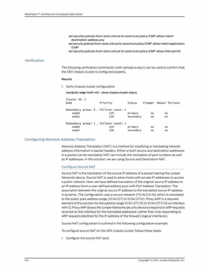
set security policies from-zone untrust to-zone trust policy ICMP-allowmatchdestination-address any
setsecuritypolicies from-zoneuntrust to-zonetrustpolicy ICMP-allowmatchapplicationICMP
set security policies from-zone untrust to-zone trust policy ICMP-allow then permit
Verification
The following verification commands (with sample output) can be used to confirm that
the SRX chassis cluster is configured properly.
Results
1. Verify chassis cluster configuration.
root@vdc-edge-fw01-n0> show chassis cluster status
Cluster ID: 1 Node Priority Status Preempt Manual failover
Redundancy group: 0 , Failover count: 1 node0 129 primary no no node1 128 secondary no no
Redundancy group: 1 , Failover count: 1 node0 129 primary no no node1 128 secondary no no
Configuring Network Address Translation
Network Address Translation (NAT) is a method for modifying or translating network
address information in packet headers. Either or both source and destination addresses
in a packet can be translated. NAT can include the translation of port numbers as well
as IP addresses. In this solution, we are using Source and Destination NAT.
Configure Source NAT
Source NAT is the translation of the source IP address of a packet leaving the Juniper
Networks device. Source NAT is used to allow hosts with private IP addresses to access
a public network. Here, we have defined translation of the original source IP address to
an IP address from a user-defined address pool with Port Address Translation. The
association between the original source IP address to the translated source IP address
is dynamic. The configuration uses a source network (172.16.0.0/16) which is translated
to the public pool address range (10.94.127.1 to 10.94.127.10). Proxy ARP is a required
element of the solution for the address range 10.94.127.1/32 to 10.94.127.11/32 on interface
reth1.0.ProxyARPallows the JuniperNetworks securitydevice to respond toARP requests
received on the interface for the translated addresses (rather than only responding to
ARP requests destined for the IP address of the firewall’s logical interfaces).
Source NAT configuration is outlined in the following configuration example.
To configure source NAT on the SRX chassis cluster, follow these steps:
1. Configure the source NAT pool.
Copyright © 2014, Juniper Networks, Inc.144
MetaFabric™ Architecture Virtualized Data Center

[edit]set security nat source pool public-pool address 10.94.127.1/32 to 10.94.127.10/32
2. Configure the source NAT rule set.
[edit]set security nat source rule-set Internet-access from zone trustset security nat source rule-set Internet-access to zone untrustset security nat source rule-set Internet-access rule datacenter match source-address172.16.0.0/16
set security nat source rule-set Internet-access rule datacenter matchdestination-address 0.0.0.0/0
set security nat source rule-set Internet-access rule datacenter then source-nat poolpublic-pool
3. ConfigureproxyARPon theoutboundNAT interface (reth1, or untrust, in this example).
[edit]set security nat proxy-arp interface reth1.0 address 10.94.127.1/32 to 10.94.127.10/32
Configure Destination NAT
Destination NAT is the translation of the destination IP address of a packet entering the
Juniper Networks device. Destination NAT is used to redirect traffic destined to a virtual
host (identified by the original destination IP address) to the real host (identified by the
translated destination IP address). Destination NAT allows connections to be initiated
only for incoming network connections—for example, from the Internet to a private
network. The following configuration parameters were used in the below example:
1. Destination NAT pool dst-nat-SA-pool1 contains the IP address 10.94.63.24/32. This
device is a Juniper Networks SA Series SSL VPN Appliance (Remote Access Server).
This device can also be provisioned as a virtual appliance.
2. DestinationNAT rule setSAwith ruleSA-rule1 tomatchpackets received todestination
IPaddress 10.94.127.33/32. Formatchingpackets, thedestinationaddress is translated
to the address in the dst-nat-pool-1 pool.
3. Proxy ARP for the address 10.94.127.33/32 on interface reth1.0. This allows the Juniper
Networks security device to respond to ARP requests received on the interface for
that address.
4. Security policies to permit traffic from the untrust zone to the translated destination
IP address in the trust zone.
NOTE: When destination NAT is performed, the destination IP address istranslated according to configured destination NAT rules and then securitypolicies are applied.
To configure destination NAT on the SRX chassis cluster, follow these steps:
1. Configure the destination NAT pool.
[edit]set security nat destination pool dst-nat-SA-pool1 address 10.94.63.24/32
145Copyright © 2014, Juniper Networks, Inc.
Chapter 7: Security Configuration
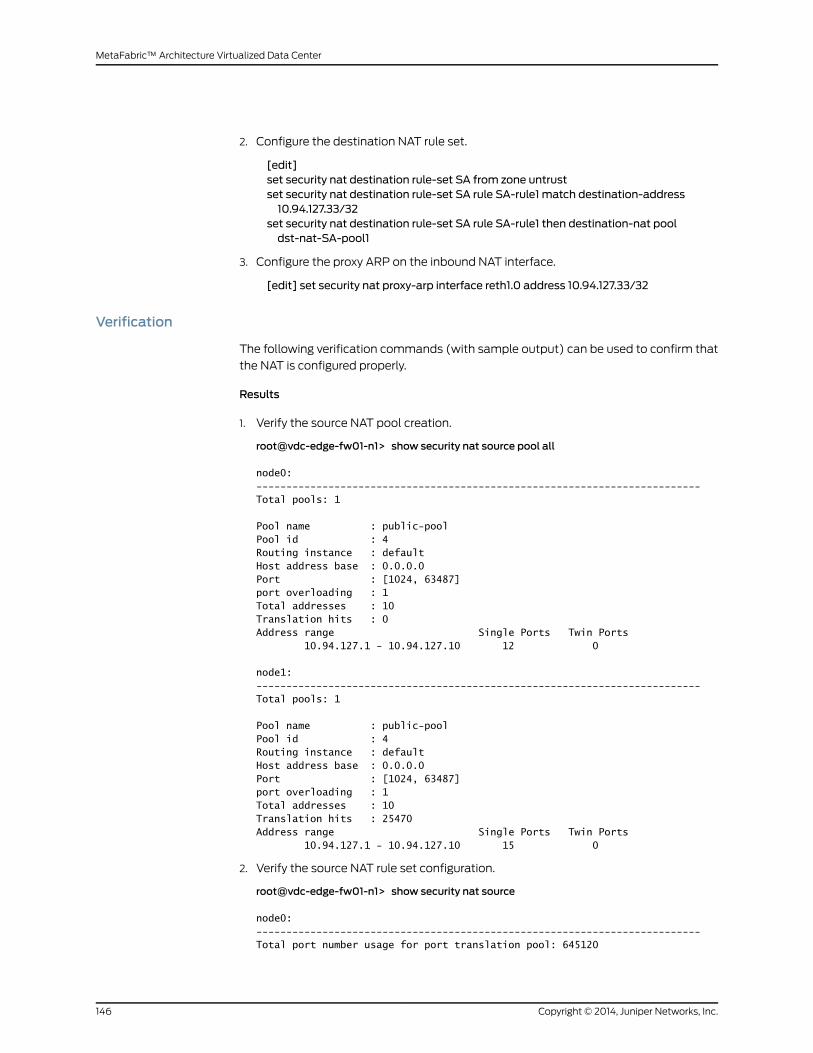
2. Configure the destination NAT rule set.
[edit]set security nat destination rule-set SA from zone untrustset security nat destination rule-set SA rule SA-rule1 match destination-address10.94.127.33/32
set security nat destination rule-set SA rule SA-rule1 then destination-nat pooldst-nat-SA-pool1
3. Configure the proxy ARP on the inbound NAT interface.
[edit] set security nat proxy-arp interface reth1.0 address 10.94.127.33/32
Verification
The following verification commands (with sample output) can be used to confirm that
the NAT is configured properly.
Results
1. Verify the source NAT pool creation.
root@vdc-edge-fw01-n1> show security nat source pool all
node0:--------------------------------------------------------------------------Total pools: 1
Pool name : public-poolPool id : 4Routing instance : defaultHost address base : 0.0.0.0Port : [1024, 63487] port overloading : 1Total addresses : 10Translation hits : 0Address range Single Ports Twin Ports 10.94.127.1 - 10.94.127.10 12 0
node1:--------------------------------------------------------------------------Total pools: 1
Pool name : public-poolPool id : 4Routing instance : defaultHost address base : 0.0.0.0Port : [1024, 63487] port overloading : 1Total addresses : 10Translation hits : 25470Address range Single Ports Twin Ports 10.94.127.1 - 10.94.127.10 15 0
2. Verify the source NAT rule set configuration.
root@vdc-edge-fw01-n1> show security nat source
node0:--------------------------------------------------------------------------Total port number usage for port translation pool: 645120
Copyright © 2014, Juniper Networks, Inc.146
MetaFabric™ Architecture Virtualized Data Center

Maximum port number for port translation pool: 268435456Total pools: 1Pool Address Routing PAT Total
Name Range Instance Addresspublic-pool 10.94.127.1-10.94.127.10 default yes 10
Total rules: 1Rule name Rule set From To Actiondatacenter Internet-access trust untrust public-pool
node1:--------------------------------------------------------------------------Total port number usage for port translation pool: 645120Maximum port number for port translation pool: 268435456Total pools: 1Pool Address Routing PAT Total
Name Range Instance Addresspublic-pool 10.94.127.1-10.94.127.10 default yes 10
Total rules: 1Rule name Rule set From To Actiondatacenter Internet-access trust untrust public-pool
3. Verify source NAT rules, match conditions, actions, and rule order .
root@vdc-edge-fw01-n1> show security nat source rule all
node0:--------------------------------------------------------------------------Total rules: 1Total referenced IPv4/IPv6 ip-prefixes: 2/0
source NAT rule: datacenter Rule-set: Internet-access Rule-Id : 1 Rule position : 1 From zone : trust To zone : untrust Match Source addresses : 172.16.0.0 - 172.16.255.255 Destination addresses : 0.0.0.0 - 255.255.255.255 Destination port : 0 - 0 Action : public-pool Persistent NAT type : N/A Persistent NAT mapping type : address-port-mapping Inactivity timeout : 0 Max session number : 0 Translation hits : 0
node1:--------------------------------------------------------------------------Total rules: 1 Total referenced IPv4/IPv6 ip-prefixes: 2/0source NAT rule: datacenter Rule-set: Internet-access Rule-Id : 1 Rule position : 1 From zone : trust To zone : untrust
147Copyright © 2014, Juniper Networks, Inc.
Chapter 7: Security Configuration

Match Source addresses : 172.16.0.0 - 172.16.255.255 Destination addresses : 0.0.0.0 - 255.255.255.255 Destination port : 0 - 0 Action : public-pool Persistent NAT type : N/A Persistent NAT mapping type : address-port-mapping Inactivity timeout : 0 Max session number : 0 Translation hits : 25621
{primary:node1}
Configuring Intrusion Detection and Prevention
The Junos OS intrusion detection and prevention (IDP) policy enables you to selectively
enforce various attack detection and prevention techniques on network traffic passing
through an IDP-enabled device. It allows you to define policy rules to match a section of
traffic based on a zone, network, and application, and then take active or passive
preventive actions on that traffic. An IDP policy defines how your device handles the
network traffic. It allowsyou toenforcevariousattackdetectionandprevention techniques
on traffic traversing your network.
A policy is made up of rulebases, and each rulebase is comprised of a set of rules. You
define ruleparameters, suchas trafficmatchconditions, action, and logging requirements,
and then add the rules to rule bases. After you create an IDP policy by adding rules in one
ormore rulebases, you can select that policy to be the active policy on your device. Junos
OS allows you to configure multiple IDP policies, but a device can have only one active
IDP policy at a time. You can install the same IDP policy onmultiple devices, or you can
install a unique IDP policy on each device in your network. A single policy can contain
only one instance of any type of rulebase.
For transit traffic to pass through IDP inspection, you configure a security policy and
enable IDP application services on all traffic that you want to inspect. Security policies
contain rules defining the types of traffic permitted on the network and how the traffic
is treated inside the network. Enabling IDP in a security policy directs traffic thatmatches
the specified criteria to be checked against the IDP rulebases.
NOTE: Theactionset in thesecuritypolicyactionmustbepermit.Youcannotenable IDP for traffic that the device denies or rejects.
Copyright © 2014, Juniper Networks, Inc.148
MetaFabric™ Architecture Virtualized Data Center

To install and configure IDP on the SRX chassis cluster, follow these steps:
Install an IDP license to enable IDP signature updates. In order to download and use the
predefined attack signatures in a policy, the IDP licensemust be installed. If you are using
only customsignatures, youdonotneedan IDP license.Onceyour license file is purchased
and available, install the license using the Junos OS terminal.
1. root@vdc-edge-fw01-n1> request system license add terminal
[Type ^D at a new line to end input, enter blank line between each license key]Serial No : AB0813AA0021Model : SRX3600Features : SRX3600-APPSEC-A-1 0Issue Date : 17-Dec-2013Expiration Date : 16-Dec-2014License Id : JUNOS466173License Key : JUNOS466173 aeaqea qmifbd aobrgn aucmbq giyqqb qcdw7l rqbea4 ujbpu2 q4esq2 sucbpr wrroiw w5kgvv 35oxsq ne4ynp ljbecm c5ug52 3s6cbj ldpuqj xny
2. Once you install the license, check for feature “idp-sig”.
root@vdc-edge-fw01-n0> show system license
License usage: Licenses Licenses Licenses Expiry Feature name used installed needed idp-sig 1 1 0 2014-12-15 16:00:00 PST appid-sig 0 2 0 2014-12-15 16:00:00 PST logical-system 1 1 0 permanentLicenses installed: License identifier: JUNOS466166 License version: 2 Valid for device: AB0813AA0014 Features: idp-sig - IDP Signature date-based, 2013-12-16 16:00:00 PST - 2014-12-15 16:00:00 PST
License identifier: JUNOS466167 License version: 2 Valid for device: AB0813AA0014 Features: appid-sig - APPID Signature date-based, 2013-12-16 16:00:00 PST - 2014-12-15 16:00:00 PST License identifier: JUNOS466168 License version: 2 Valid for device: AB0813AA0014 Features: appid-sig - APPID Signature date-based, 2013-12-16 16:00:00 PST - 2014-12-15 16:00:00 PST
149Copyright © 2014, Juniper Networks, Inc.
Chapter 7: Security Configuration

NOTE: If configuring a firewall cluster, a firewall clustering license isrequired on both nodes of the cluster. The license is device specific.
3. Download and install the signature database. After the IDP license is installed, the
iDP signature database can be downloaded and installed by performing the following
steps:
• Makesure thedevicehas thenecessary configuration for connectivity to the Internet.
A name server must be configured.
• Configure the signature database URL.
set security idp security-package url https://services.netscreen.com/cgi-bin/index.cgi
4. Verify the version of the signature database in the Signature DB server. Look for
“successfully retrieved”. In this example, the version in the server is 2327.
root@vdc-edge-fw01-n0> request security idp security-package download check-server
node0:--------------------------------------------------------------------------Successfully retrieved from(https://services.netscreen.com/cgi-bin/index.cgi).Version info:2345(Detector=12.6.140140207, Templates=2345)
{primary:node0}
5. Download the signature database (operational command, not configuration
command).
root@vdc-edge-fw01-n0> request security idp security-package download
node0:--------------------------------------------------------------------------Will be processed in async mode. Check the status using the status checking CLI
{primary:node0}root@vdc-edge-fw01-n0> request security idp security-package download status node0:--------------------------------------------------------------------------In progress:platforms.xml.gz 100 % 250 Bytes/ 250 Bytes
{primary:node0}root@vdc-edge-fw01-n0> request security idp security-package download status
node0:--------------------------------------------------------------------------Done;Successfully downloaded from(https://services.netscreen.com/cgi-bin/index.cgi)and synchronized to backup.Version info:2345(Wed Feb 12 19:13:53 2014 UTC, Detector=12.6.140140207)
{primary:node0}
6. Verify the progress of the IDP signature download.
root@vdc-edge-fw01-n0> request security idp security-package download status
Copyright © 2014, Juniper Networks, Inc.150
MetaFabric™ Architecture Virtualized Data Center

node0:--------------------------------------------------------------------------In progress:platforms.xml.gz 100 % 250 Bytes/ 250 Bytes
{primary:node0}root@vdc-edge-fw01-n0> request security idp security-package download status
node0:--------------------------------------------------------------------------Done;Successfully downloaded from(https://services.netscreen.com/cgi-bin/index.cgi)and synchronized to backup.Version info:2345(Wed Feb 12 19:13:53 2014 UTC, Detector=12.6.140140207)
7. Install the IDP database.
request security idp security-package install
8. Monitor the status of the install command.
root@vdc-edge-fw01-n0> request security idp security-package install status
node0:--------------------------------------------------------------------------In progress:Updating with new attack or detector for existing running policy...
node1:--------------------------------------------------------------------------Done;Attack DB update : successful - [UpdateNumber=2345,ExportDate=Wed Feb 12 19:13:53 2014 UTC,Detector=12.6.140140207] Updating control-plane with new detector : successful Updating data-plane with new attack or detector : successful (The last known good detector link has been updated with the new detector)
9. Once the security policy is configured and the action is set to “permit”, enable IDP
under “application services”. This redirects traffic that matches the security policy to
the IDP service for inspection. Below is an example of traffic flowing from the trust to
the untrust Internet-access security policy.
root@vdc-edge-fw01-n0# show security policies from-zone trust to-zone untrust policyInternet-access | display set
set security policies from-zone trust to-zone untrust policy Internet-accessmatchsource-address any
set security policies from-zone trust to-zone untrust policy Internet-accessmatchdestination-address any
set security policies from-zone trust to-zone untrust policy Internet-accessmatchapplication junos-http
set security policies from-zone trust to-zone untrust policy Internet-accessmatchapplication junos-https
set security policies from-zone trust to-zone untrust policy Internet-accessmatchapplication junos-http-ext
set security policies from-zone trust to-zone untrust policy Internet-accessmatchapplication junos-ntp
set security policies from-zone trust to-zone untrust policy Internet-accessmatchapplication junos-dns-udp
set security policies from-zone trust to-zone untrust policy Internet-accessmatchapplication ICMP
151Copyright © 2014, Juniper Networks, Inc.
Chapter 7: Security Configuration
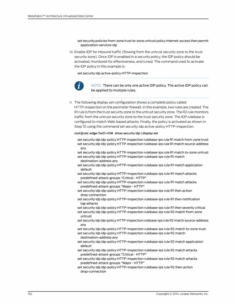
set security policies from-zone trust to-zone untrust policy Internet-access thenpermitapplication-services idp
10. Enable IDP for inbound traffic (flowing from the untrust security zone to the trust
security zone). Once IDP is enabled in a security policy, the IDP policy should be
activated, monitored for effectiveness, and tuned. The command used to activate
the IDP policy in this example is:
set security idp active-policy HTTP-inspection
NOTE: There can be only one active IDP policy. The active IDP policy canbe applied tomultiple rules.
11. The following display set configuration shows a complete policy called
HTTP-inspection on the perimeter firewall. In this example, two rules are created. The
R1 rule is from the trust security zone to the untrust security zone. TheR2 rulemonitors
traffic from the untrust security zone to the trust security zone. The IDP rulebase is
configured to matchWeb-based attacks. Finally, the policy is activated as shown in
Step 10 using the command set security idp active-policy HTTP-inspection.
root@vdc-edge-fw01-n0# show security idp | display set
set security idp idp-policy HTTP-inspection rulebase-ips rule R1match from-zone trustset security idp idp-policy HTTP-inspection rulebase-ips rule R1match source-addressany
set security idp idp-policy HTTP-inspection rulebase-ips rule R1match to-zone untrustset security idp idp-policy HTTP-inspection rulebase-ips rule R1 matchdestination-address any
set security idp idp-policy HTTP-inspection rulebase-ips rule R1 match applicationdefault
set security idp idp-policy HTTP-inspection rulebase-ips rule R1 match attackspredefined-attack-groups "Critical - HTTP"
set security idp idp-policy HTTP-inspection rulebase-ips rule R1 match attackspredefined-attack-groups "Major - HTTP"
set security idp idp-policy HTTP-inspection rulebase-ips rule R1 then actiondrop-connection
set security idp idp-policy HTTP-inspection rulebase-ips rule R1 then notificationlog-attacks
set security idp idp-policy HTTP-inspection rulebase-ips rule R1 then severity criticalset security idp idp-policy HTTP-inspection rulebase-ips rule R2match from-zoneuntrust
set security idp idp-policyHTTP-inspection rulebase-ips rule R2match source-addressany
set security idp idp-policy HTTP-inspection rulebase-ips rule R2match to-zone trustset security idp idp-policy HTTP-inspection rulebase-ips rule R2matchdestination-address any
set security idp idp-policy HTTP-inspection rulebase-ips rule R2match applicationdefault
set security idp idp-policy HTTP-inspection rulebase-ips rule R2match attackspredefined-attack-groups "Critical - HTTP"
set security idp idp-policy HTTP-inspection rulebase-ips rule R2match attackspredefined-attack-groups "Major - HTTP"
set security idp idp-policy HTTP-inspection rulebase-ips rule R2 then actiondrop-connection
Copyright © 2014, Juniper Networks, Inc.152
MetaFabric™ Architecture Virtualized Data Center
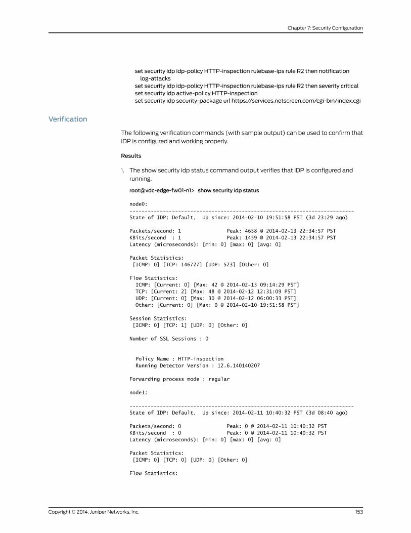
set security idp idp-policy HTTP-inspection rulebase-ips rule R2 then notificationlog-attacks
set security idp idp-policy HTTP-inspection rulebase-ips rule R2 then severity criticalset security idp active-policy HTTP-inspectionset security idp security-package url https://services.netscreen.com/cgi-bin/index.cgi
Verification
The following verification commands (with sample output) can be used to confirm that
IDP is configured and working properly.
Results
1. The show security idp status command output verifies that IDP is configured and
running.
root@vdc-edge-fw01-n1> show security idp status
node0:--------------------------------------------------------------------------State of IDP: Default, Up since: 2014-02-10 19:51:58 PST (3d 23:29 ago)
Packets/second: 1 Peak: 4658 @ 2014-02-13 22:34:57 PSTKBits/second : 1 Peak: 1459 @ 2014-02-13 22:34:57 PSTLatency (microseconds): [min: 0] [max: 0] [avg: 0]
Packet Statistics: [ICMP: 0] [TCP: 146727] [UDP: 523] [Other: 0]
Flow Statistics: ICMP: [Current: 0] [Max: 42 @ 2014-02-13 09:14:29 PST] TCP: [Current: 2] [Max: 48 @ 2014-02-12 12:31:09 PST] UDP: [Current: 0] [Max: 30 @ 2014-02-12 06:00:33 PST] Other: [Current: 0] [Max: 0 @ 2014-02-10 19:51:58 PST]
Session Statistics: [ICMP: 0] [TCP: 1] [UDP: 0] [Other: 0]
Number of SSL Sessions : 0
Policy Name : HTTP-inspection Running Detector Version : 12.6.140140207
Forwarding process mode : regular
node1:
--------------------------------------------------------------------------State of IDP: Default, Up since: 2014-02-11 10:40:32 PST (3d 08:40 ago)
Packets/second: 0 Peak: 0 @ 2014-02-11 10:40:32 PSTKBits/second : 0 Peak: 0 @ 2014-02-11 10:40:32 PSTLatency (microseconds): [min: 0] [max: 0] [avg: 0]
Packet Statistics: [ICMP: 0] [TCP: 0] [UDP: 0] [Other: 0]
Flow Statistics:
153Copyright © 2014, Juniper Networks, Inc.
Chapter 7: Security Configuration

ICMP: [Current: 0] [Max: 0 @ 2014-02-11 10:40:32 PST] TCP: [Current: 0] [Max: 0 @ 2014-02-11 10:40:32 PST] UDP: [Current: 0] [Max: 0 @ 2014-02-11 10:40:32 PST] Other: [Current: 0] [Max: 0 @ 2014-02-11 10:40:32 PST]
Session Statistics: [ICMP: 0] [TCP: 0] [UDP: 0] [Other: 0]
Number of SSL Sessions : 0
Policy Name : HTTP-inspection Running Detector Version : 12.6.140140207
2. Verify that the IDP attack table is configured and running on the primary node.
root@vdc-edge-fw01-n1> show security idp attack table
node0:--------------------------------------------------------------------------
node1:--------------------------------------------------------------------------
{primary:node1}
3. Verify that the IDP application statistics are incrementing based on the configured
IDP rule set. (output is truncated to show the relevant packet counter on node1.)
root@vdc-edge-fw01-n1> show security idp application-statistics
node0:--------------------------------------------------------------------------IDP applications:
application type packet countDNS 0HTTP 0LDAP 0SSL 0MSRPC 0MSSQL 0MYSQL 0BGP 0
node1:--------------------------------------------------------------------------IDP applications:
application type packet countDNS 36HTTP 4147LDAP 0SSL 747MSRPC 0MSSQL 0MYSQL 0
Copyright © 2014, Juniper Networks, Inc.154
MetaFabric™ Architecture Virtualized Data Center

Host Security
• Overview on page 155
• Configuring the Firefly Host on page 156
• Verification on page 159
Overview
Juniper Networks Firefly Host is a virtualized firewall that runs on VMware ESX/ESXi for
to secure intra-virtual machine (VM) and inter-VM traffic. Juniper Firefly Host has three
main components:
• Firefly Host Security Design VM (SVM)—This provides a central management server.
It provides charts, tables, and graphs, and collects the logs from the security policy
which helps to adjust the virtualized environment.
• Firefly Host Security VM—This is installed on each host of VMware ESX/ESXi to be
secured. Firefly Host Security VM acts as a conduit to the Firefly Host kernel module
that it inserts into the hypervisors of hosts. The Firefly Host Security VMmaintains the
policy and logging information.
• Firefly Host kernelmodule—Virtualized network traffic is secured and analyzed against
the security policy for all VM on the ESX/ESXi host in the Firefly Host kernel module
installed on the host. All connections are processed and firewall security policy is
enforced in the Firefly Host Series kernel module.
FireflyHostprotects theVMaswell as thehypervisor.When it is deployed into theVMware
environment, Firefly Host Security VM is installed on VMware ESX/ESXi host
(Figure50onpage 155), it inserts theFireflyHost kernelmodule into thehost’s hypervisor
between the virtual network interface card (NIC) and virtual switch (vSwitch) or
distributed virtual switch (DvSW).
Firefly Host supports vMotion, enabling mobility of both the VM and the Firefly Host. In
cases where a VM is moved to a different virtual machine, the security policy assigned
to that VMmoves along with the virtual machine. Because Firefly Host is supported by
vMotion, this VMmobility does not require any additional configuration.
Figure 50: Logical View of Juniper Networks Firefly Host Installation
155Copyright © 2014, Juniper Networks, Inc.
Chapter 7: Security Configuration
Firefly Host Security Design VMalsomanages the entire Security VirtualMachine (SVM),
defining security policies, configuring antivirus, IDS, and so on. To secure ESX/ESXi hosts
and VMs, we need to deploy SVM on the ESX/ESXi hosts first. As soon as you have
deployedSVMon each ESX/ESXi host, it will be secured and insert the Firefly Host kernel
on the ESX/ESXi hypervisor.
Firefly Host Security Design VM can bemanaged through aWeb GUI that enables you
to define firewall security policy for all the VMs, similar to how you configure a physical
SRX firewall. Traffic can be controlled between two VMs running on one ESX/ESXi host,
andmultiple VMs running onmultiple ESX/ESXi hosts.
Firefly Host Security Design VM pushes the firewall security policy to the SVM kernel
module. When traffic enters through a physical network adapter on an ESX/ESXi host,
it travels to the virtual switch or distributed switch first, then visits the Firefly Host kernel
module before being forwarded to the appropriate VM. As the security policy resides in
the kernel module and is based on the security policies, traffic is allowed or denied to or
from the VM.
Configuring the Firefly Host
When you install SVMon the hosts, all the VMs are unsecured by default. Before defining
security policies, youmust secure the VM environment.
Step-by-Step Procedure
Copyright © 2014, Juniper Networks, Inc.156
MetaFabric™ Architecture Virtualized Data Center

To configure Firefly Host, follow these steps:
1. The first step in configuration is to log in to the Firefly Host to select the VMs that
should be secured. The example below contains several ESXi hosts under Unsecured
Network and Secured Network. On the left side (under Unsecured Network),
Win2012-Exch02 VM is not secured. On the right side (under Secured Network),
Win2012-Exch06 VM is secured. To secure or unsecure VM, you need to select or
deselect the check box in front of the VM and click on Secure or Unsecure in the
Settings tab. You also need to secure the port groupwhen securing a VM (this is done
similarly by selecting Secure in the Settings tab for a dvPort Group).
Figure 51: An Example dvPort Group
2. Configureagroup foronesetofapplications. Theexamplebelowshowsanapplication
name (MediaWiki) that represents a single group. Additional application groups can
be created using Add Smart Group under Security Settings, Group tab in Firefly Host.
Define vi.notes which contains the keyword MediaWiki in the Firefly Host. By doing
this, it will detect all VMs that have the keyword MediaWiki in an annotation of VM.
Beforedefining security policies, it is a good idea to survey theexistingVMenvironment
to obtain a list of the applications hosted in the data center. Creating Smart Groups
initially will save time during security policy configuration.
Figure 52: Configure an Application Group
157Copyright © 2014, Juniper Networks, Inc.
Chapter 7: Security Configuration

3. Once groups are defined in Firefly Host, an additional step is required on the vCenter
Server.At theMediaWikiVMsummary tabunder vCenterServer, add thesamekeyword
you used in vi notes in the Annotations field in Step 2. This is required to enable the
FireflyHost toproperlydetect thevirtualmachine. In thebelowexample, theMediaWiki
Group in the Firefly Host will detect all VMs that are properly annotated with the tag
MediaWiki.
Figure 53: The Annotation Allows Firefly Host to Detect Related VMs
4. Next, define security policies in the Firewall area of the Firefly Host. Also define an
initial, Global rule under Global Policy in Policy Group. This rule creation applies to all
VMs in the environment, enabling security even if an application group isn’t properly
created. To create specific rules, navigate to Policy Groups in the left pane. You will
notice that the policy groups contain both Inbound andOutbound rules. Inbound rule
means traffic is coming into the VM and Outbound rule means traffic is originating
from the VM. Below is an example rule that allows HTTP, HTTPS, and ICMP inbound
to the MediaWiki application VM.
Copyright © 2014, Juniper Networks, Inc.158
MetaFabric™ Architecture Virtualized Data Center

Figure 54: Define Security Policies
Verification
Many network administrators are required to monitor security status in the data center.
The administrators must be able to see details on allowed traffic, as well as blocked or
anomalous traffic. This information is found in the Logswindow. Logging can be enabled
or disabled on a per policy basis. You can also enable logging for all the policies. Please
keep in mind that enabling logging for all policies can have an effect on CPU utilization
and can introduce network congestion or packet drops. Because of this, we do not
recommend enabling logging for all policies.
To see policy logs, you need to enable logging per policy. Once logging is enabled, the
FireflyHost can filter by source IPaddress, destination IPaddress, or protocol. This filtering
is performed in the advanced view of the logging screen.
For more information on Firefly Host configuration, troubleshooting, and best practices,
see the Firefly Host Administration Guide at:
Juniper Networks Firefly Host - Installation and Administration Guide for VMware
159Copyright © 2014, Juniper Networks, Inc.
Chapter 7: Security Configuration

Copyright © 2014, Juniper Networks, Inc.160
MetaFabric™ Architecture Virtualized Data Center
CHAPTER 8
Data Center Services
• Data Center Services Overview on page 161
• Configuring Compute Hardware on page 162
• Virtualization on page 186
• EMC Storage Overview on page 204
• Load Balancing on page 227
• Applications on page 235
Data Center Services Overview
This section covers the configuration of services in the virtualized IT data center. The
areas covered in this chapter include:
• Compute
• Compute overview
• Hardware overview
• Compute configuration
• Configure management
• Configure switching
• Virtualization
• Virtualization overview
• Configure virtualization
• EMC storage configuration
• Load balancing
• Overview
• Configuration
• Applications
161Copyright © 2014, Juniper Networks, Inc.

• Microsoft Exchange
Configuring Compute Hardware
• Overview on page 162
• Requirements on page 162
• Verification on page 185
Overview
The Juniper MetaFabric 1.0 solution is designed around optimizing network, security,
virtualization, mobility, and visibility in the data center environment. To that end, all of
the data center network, security, and resiliency features are designed to support the
hosting of applications in such a way that provides the highest quality user experience.
This section covers the configuration of the physical compute hosts that reside in the
data center.
Requirements
The solution requirements that guided testing and validation include:
• Solution must support lossless Ethernet.
• Solution must provide redundant network connectivity using all available bandwidth.
• Solution must support moving a virtual machine (VM) between hosts.
• Solution must support high availability of a VM.
• Solutionmust support virtual network identificationusingLinkLayerDiscoveryProtocol
(LLDP).
• Solution must provide physical and virtual visibility and reporting of VMmovements.
• Solution must support lossless Ethernet for storage transit.
• Solution must support booting a server from the storage array.
The IBM Flex Chassis was selected as the physical compute host. High-level
implementation details include:
• IBM Flex server is configured with multiple ESXi hosts hosting all the VMs running the
business-critical applications (SharePoint, Exchange, Media-wiki, andWWW).
• Distributed vSwitch is configured betweenmultiple physical ESXi hosts configured in
IBM hosts.
Topology
The topologyused in thedatacenter compute, virtualization, andstoragedesign is shown
in Figure 55 on page 163.
Copyright © 2014, Juniper Networks, Inc.162
MetaFabric™ Architecture Virtualized Data Center

Figure 55: Compute and Virtualization as Featured in theMetaFabric 1.0Solution
Compute Hardware Overview
The IBM System x3750M4 is a 4-socket server that features a streamlined design,
optimized for performance. This solution uses two IBM standalone system 3750s as an
Infra Cluster. Infra Cluster is hosting all infrastructure-related VMs such as Junos Space,
Firefly Host Security Design VM, and Virtual Center server. The IBM System 3750 has
dedicated twomanagement ports, which are connected to amanagement switch as a
LAG. Figure 56 on page 163 shows the IBM System x3750M4.
Figure 56: IBM x3750M4
163Copyright © 2014, Juniper Networks, Inc.
Chapter 8: Data Center Services
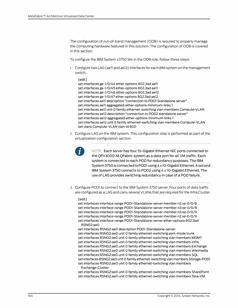
The configuration of out-of-bandmanagement (OOB) is required to properly manage
the computing hardware featured in this solution. The configuration of OOB is covered
in this section.
To configure the IBM System x3750M4 in the OOB role, follow these steps:
1. Configure twoLAG(ae11 andae12) interfaces for each IBMsystemon themanagement
switch.
[edit]set interfaces ge-1/0/44 ether-options 802.3ad ae11set interfaces ge-1/0/45 ether-options 802.3ad ae11set interfaces ge-1/0/46 ether-options 802.3ad ae12set interfaces ge-1/0/47 ether-options 802.3ad ae12set interfaces ae11 description "connection to POD1 Standalone server"set interfaces ae11 aggregated-ether-optionsminimum-links 1set interfaces ae11 unit 0 family ethernet-switching vlanmembers Compute-VLANset interfaces ae12 description "connection to POD2 standalone server"set interfaces ae12 aggregated-ether-optionsminimum-links 1set interfaces ae12 unit 0 family ethernet-switching vlanmembers Compute-VLANset vlans Compute-VLAN vlan-id 800
2. Configure LAG on the IBM system. This configuration step is performed as part of the
virtualization configuration section.
NOTE: Each server has four 10-Gigabit Ethernet NIC ports connected tothe QFX3000-MQFabric system as a data port for all VM traffic. Eachsystem is connected to each POD for redundancy purposes. The IBMSystem3750 isconnectedtoPOD1using4x 10-GigabitEthernet.AsecondIBM System 3750 connects to POD2 using 4 x 10-Gigabit Ethernet. Theuse of LAG provides switching redundancy in case of a POD failure.
3. Configure POD1 to connect to the IBM System 3750 server. Four ports of data traffic
are configured as a LAGand carry several VLANs that are required for the Infra Cluster.
[edit]set interfaces interface-range POD1-Standalone-server member n2:xe-0/0/8set interfaces interface-range POD1-Standalone-server member n3:xe-0/0/8set interfaces interface-range POD1-Standalone-server member n3:xe-0/0/9set interfaces interface-range POD1-Standalone-server member n2:xe-0/0/9set interfaces interface-range POD1-Standalone-server ether-options 802.3adRSNG2:ae0
set interfaces RSNG2:ae0 description POD1-Standalone-serverset interfaces RSNG2:ae0 unit 0 family ethernet-switching port-mode trunkset interfaces RSNG2:ae0 unit 0 family ethernet-switching vlanmembers MGMTset interfaces RSNG2:ae0 unit 0 family ethernet-switching vlanmembers Infraset interfaces RSNG2:ae0 unit 0 family ethernet-switching vlanmembers Exchangeset interfaces RSNG2:ae0 unit 0 family ethernet-switching vlanmembersWikimediaset interfaces RSNG2:ae0 unit 0 family ethernet-switching vlanmembers SQLset interfacesRSNG2:ae0unit0 familyethernet-switchingvlanmembersStorage-POD1set interfaces RSNG2:ae0 unit 0 family ethernet-switching vlanmembersExchange-Cluster
set interfaces RSNG2:ae0 unit 0 family ethernet-switching vlanmembers SharePointset interfaces RSNG2:ae0 unit 0 family ethernet-switching vlanmembers Tera-VM
Copyright © 2014, Juniper Networks, Inc.164
MetaFabric™ Architecture Virtualized Data Center

set interfacesRSNG2:ae0unit0familyethernet-switchingvlanmembersSecurity-Mgmtset interfaces RSNG2:ae0 unit 0 family ethernet-switching vlanmembers Vmotionset interfaces RSNG2:ae0 unit 0 family ethernet-switching vlanmembers VM-FTset interfaces RSNG2:ae0 unit 0 family ethernet-switching vlanmembersRemote-Access
4. Configure POD2 for connection to the second IBM System 3750.
[edit]set interfaces interface-range IBM-Standalonemember "n3:xe-0/0/[26-27]"set interfaces interface-range IBM-Standalonemember "n5:xe-0/0/[26-27]"set interfaces interface-range IBM-Standalone ether-options 802.3ad RSNG3:ae1set interfaces RSNG3:ae1 description POD2-IBM-Standaloneset interfaces RSNG3:ae1 unit 0 family ethernet-switching port-mode trunkset interfaces RSNG3:ae1 unit 0 family ethernet-switching vlanmembers MGMTset interfacesRSNG3:ae1unit0 familyethernet-switchingvlanmembersStorage-POD2set interfaces RSNG3:ae1 unit 0 family ethernet-switching vlanmembers Infraset interfaces RSNG3:ae1 unit 0 family ethernet-switching vlanmembers SQLset interfaces RSNG3:ae1 unit 0 family ethernet-switching vlanmembers SharePointset interfaces RSNG3:ae1 unit 0 family ethernet-switching vlanmembersExchange-cluster
set interfaces RSNG3:ae1 unit 0 family ethernet-switching vlanmembers Exchangeset interfaces RSNG3:ae1 unit 0 family ethernet-switching vlanmembersWikimediaset interfaces RSNG3:ae1 unit 0 family ethernet-switching vlanmembers Tera-VMset interfacesRSNG3:ae1unit0 familyethernet-switchingvlanmembersSecurity-Mgmtset interfaces RSNG3:ae1 unit 0 family ethernet-switching vlanmembers Vmotionset interfaces RSNG3:ae1 unit 0 family ethernet-switching vlanmembers VM-FTset interfacesRSNG3:ae1unit0familyethernet-switchingvlanmembersRemote-Access
The MetaFabric 1.0 solution utilizes a second set of compute hardware as well. The IBM
Flex System Enterprise Chassis is a 10U next-generation server platform that features
integrated chassis management. It is a compact, high-density, high-performance, and
scalable rack-mount system. It supports up to 14 one-bay compute nodes that share
common resources, such as power, cooling, management, and I/O resources within a
single Enterprise chassis. The IBM Flex System can also support up to seven 2-bay
compute nodes or three 4-bay compute nodes when the shelves are removed. You can
mix andmatch 1-bay, 2-bay, and4-bay compute nodes tomeet specific hardware needs.
Themajor components of Enterprise Chassis (Figure 57 on page 166) are:
• Fourteen 1-bay compute node bays (can also support seven 2-bay or three 4-bay
compute nodes with the shelves removed).
• Six 2500W power modules that provide N+N or N+1 redundant power. Optionally, the
chassis can be ordered through the configure-to-order (CTO) process with six 2100W
power supplies for N+1 redundant power.
• Ten fanmodules.
• Four physical I/Omodules.
• Awide variety of networking solutions that include Ethernet, Fibre Channel, FCoE, and
• InfiniBand.
• Two IBM Chassis Management Module (CMMs). The CMM provides single-chassis
management support.
165Copyright © 2014, Juniper Networks, Inc.
Chapter 8: Data Center Services

Figure 57: IBM Flex System Enterprise Chassis (Front View)
The following components can be installed into the rear of the chassis
(Figure 58 on page 166):
• Up to two CMMs.
• Up to six 2500W or 2100W power supply modules.
• Up to six fan modules that consist of four 80-mm fanmodules and two 40-mm fan
modules.
• Additional fan modules can be installed for a total of 10 modules.
• Up to four I/Omodules.
Figure 58: IBM Flex System (Rear View)
The IBMFlexSystem includesaChassisManagementModule (CMM).TheCMMprovides
a single point of chassis management as well as the network path for remote keyboard,
video, andmouse (KVM) capability for compute nodes within the chassis. The IBM Flex
System chassis can accommodate one or two CMMs. The first is installed into CMMBay
Copyright © 2014, Juniper Networks, Inc.166
MetaFabric™ Architecture Virtualized Data Center
1, the second into CMM bay 2. Installing two CMMs provides control redundancy for the
IBM Flex System.
The CMM provides these functions:
• Power control
• Fanmanagement
• Chassis and compute node initialization
• Switch management
• Diagnostics
• Resource discovery and inventory management
• Resource alerts andmonitoring management
• Chassis and compute node power management
• Network management
The CMM has the following connectors:
• USBconnection:Canbeused for insertionofaUSBmediakey for tasks suchas firmware
updates.
• 10/100/1000-Mbps RJ45 Ethernet connection: For connection to amanagement
network. The CMM can bemanaged through this Ethernet port.
Configuring Compute Switching
The IBM Flex System also offers modular switching options to enable various levels of
switching redundancy, subscription (1:1 vs oversubscription), and switched or Pass-thru
modesofoperation.The first of thesemodulesused in thesolution is the IBMFlexSystem
Fabric CN4093 10Gb/40Gb Converged Scalable Switch. The IBM Flex System Fabric
CN4093 10Gb/40Gb Converged Scalable Switch provides unmatched scalability,
performance, convergence, and network virtualization, while also delivering innovations
to help address a number of networking concerns and providing capabilities that help
you prepare for the future.
The switch offers full Layer 2/3 switching and FCoE Full Fabric and Fibre Channel NPV
Gateway operations to deliver a converged and integrated solution, and it is installed
within the I/Omodule bays of the IBM Flex System Enterprise Chassis. The switch can
help youmigrate to a 10-Gb or 40-Gb converged Ethernet infrastructure and offers
virtualization features.
167Copyright © 2014, Juniper Networks, Inc.
Chapter 8: Data Center Services
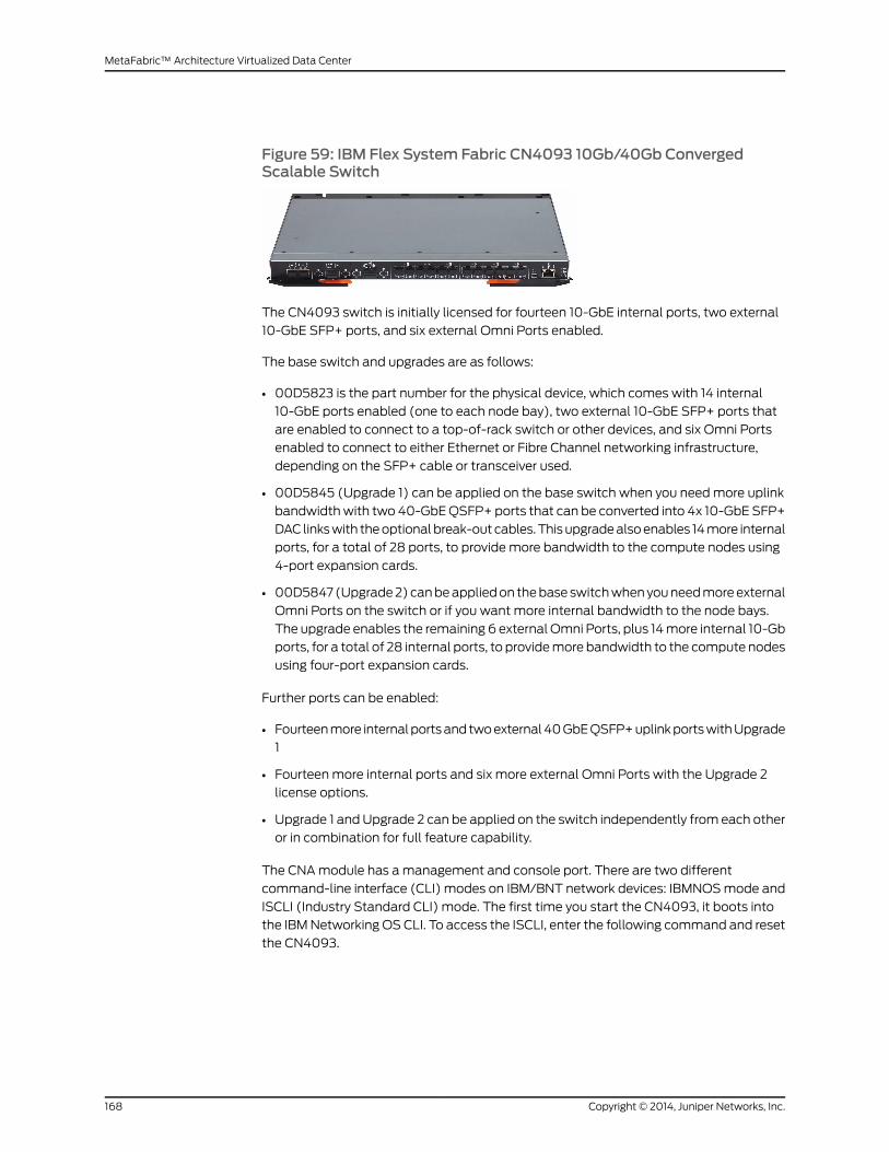
Figure 59: IBM Flex System Fabric CN4093 10Gb/40Gb ConvergedScalable Switch
The CN4093 switch is initially licensed for fourteen 10-GbE internal ports, two external
10-GbE SFP+ ports, and six external Omni Ports enabled.
The base switch and upgrades are as follows:
• 00D5823 is the part number for the physical device, which comes with 14 internal
10-GbE ports enabled (one to each node bay), two external 10-GbE SFP+ ports that
are enabled to connect to a top-of-rack switch or other devices, and six Omni Ports
enabled to connect to either Ethernet or Fibre Channel networking infrastructure,
depending on the SFP+ cable or transceiver used.
• 00D5845 (Upgrade 1) can be applied on the base switch when you needmore uplink
bandwidthwith two 40-GbEQSFP+ ports that can be converted into 4x 10-GbE SFP+
DAC linkswith theoptionalbreak-outcables.Thisupgradealsoenables 14more internal
ports, for a total of 28 ports, to provide more bandwidth to the compute nodes using
4-port expansion cards.
• 00D5847 (Upgrade2)canbeappliedon thebaseswitchwhenyouneedmoreexternal
Omni Ports on the switch or if you want more internal bandwidth to the node bays.
The upgrade enables the remaining 6 external Omni Ports, plus 14more internal 10-Gb
ports, for a total of 28 internal ports, to providemore bandwidth to the compute nodes
using four-port expansion cards.
Further ports can be enabled:
• Fourteenmore internalportsand twoexternal40GbEQSFP+uplinkportswithUpgrade
1
• Fourteenmore internal ports and six more external Omni Ports with the Upgrade 2
license options.
• Upgrade 1 andUpgrade 2 can be applied on the switch independently from each other
or in combination for full feature capability.
The CNAmodule has amanagement and console port. There are two different
command-line interface (CLI) modes on IBM/BNT network devices: IBMNOSmode and
ISCLI (Industry Standard CLI) mode. The first time you start the CN4093, it boots into
the IBMNetworking OS CLI. To access the ISCLI, enter the following command and reset
the CN4093.
Copyright © 2014, Juniper Networks, Inc.168
MetaFabric™ Architecture Virtualized Data Center

1. Reset the CN4093.
Router (config)# boot cli-mode ibmnos-cli
The switch retains your CLI selection, even when you reset the configuration to factory
defaults. The CLI boot mode is not part of the configuration settings. If you downgrade
the switch software to an earlier release, it will boot into menu-based CLI. However, the
switch retains the CLI boot mode, and will restore your CLI choice.
The secondmodular switching option deployed as part of the solution is the IBM Flex
System EN4091 10 Gb Ethernet Pass-thru Module (Figure 60 on page 169). The EN4091
10-GbEthernetPass-thruModuleoffers aone-for-oneconnectionbetweenasinglenode
bay and an I/Omodule uplink. It has nomanagement interface, and can support both
1-Gbps and 10-Gbps dual-port adapters that are installed in the compute nodes. If
quad-port adapters are installed in the compute nodes, only the first two ports have
access to the Pass-thru module ports.
The necessary 1-GbE or 10-GbEmodule (SFP, SFP+, or DAC)must also be installed in
the external ports of the pass-thru module. This configuration supports the speed (1 Gb
or 10 Gb) andmedium (fiber-optic or copper) for adapter ports on the compute nodes.
Figure 60: IBM Flex System EN4091 10Gb Ethernet Pass-thru Module
The EN4091 10Gb Ethernet Pass-thru Module has the following specifications:
• Internal ports - 14 internal full-duplex Ethernet ports that can operate at 1-Gb or 10-Gb
speeds.
• External ports - 14 ports for 1-Gb or 10-Gb Ethernet SFP+ transceivers (support for
1000BASE-SX, 1000BASE-LX, 1000BASE-T, 10GBASE-SR, or 10GBASE-LR) or SFP+
DAC.
• Unmanageddevice that has no internal Ethernetmanagement port. However, it is able
to provide its VPD to the secure management network in the Chassis Management
Module.
• Allowsdirect connection fromthe 10-GbEthernetadapters thatare installed incompute
nodes in a chassis to an externally located top-of-rack switch or other external device.
NOTE: The EN4091 10-Gb Ethernet Pass-thru Module has only 14 internalports. As a result, only two ports on each compute node are enabled, one foreachof the twomodules thatare installed in thechassis. If four-port adaptersare installed in the compute nodes, ports 3 and 4 on those adapters are notenabled.
169Copyright © 2014, Juniper Networks, Inc.
Chapter 8: Data Center Services

Configuring Compute Nodes
The Juniper MetaFabric 1.0 solution utilizes the IBM Flex System servers as the primary
compute nodes. The lab configuration utilized 5 compute nodes (of a possible 14) in
each IBM Pure Flex System. The IBM Flex System portfolio of compute nodes includes
Intel Xeon processors and IBM POWER7 processors. Depending on the compute node
design, nodes can come in one of these form factors:
• Half-widthnode:Occupiesonechassisbay, half thewidthof thechassis (approximately
215 mm or 8.5 in.). An example is the IBM Flex System x220 Compute Node.
• Full-width node: Occupies two chassis bays side-by-side, the full width of the chassis
(approximately 435mm or 17 in.). An example is the IBM Flex System p460 Compute
Node.
Thesolution labutilized the IBMFlexSystemx220computenode (Figure61onpage 170).
The IBM Flex System x220 Compute Node, machine type 7906, is the next generation
cost-optimized compute node that is designed for less demanding workloads and
low-density virtualization. The x220 is efficient and equipped with flexible configuration
options and advancedmanagement to run a broad range of workloads. The IBM Flex
System x220 Compute Node is a high-availability, scalable compute node that is
optimized to support the next-generation microprocessor technology. With a balance
of cost andsystemfeatures, the x220 is an ideal platform for general businessworkloads.
The x220 is a half-wide compute node and requires that the chassis shelf is installed in
the IBM Flex System Enterprise Chassis. The IBM Flex System x220 Compute Node
features the Intel Xeon E5-2400 series processors. The Xeon E5-2400 series processor
has models with either 4, 6, or 8 cores per processor with up to 16 threads per socket.
The x220 supports LP DDR3memory LRDIMMs, RDIMMs, and UDIMMs. The x220 server
has two 2.5-inch hot-swap drive bays accessible from the front of the blade server. On
standardmodels, the two2.5-inchdrivebaysareconnected toaServeRAIDC105onboard
SATA controller with software RAID capabilities.
The applications that are installed on the compute nodes can run natively on adedicated
physical server or they can be virtualized (in a virtual machine that is managed by a
hypervisor layer). All the compute nodes are using theVMware ESXi 5.1 operating system
as a baseline for virtualization, and all the enterprise applications are running as virtual
machines on top of the ESXi 5.1 Operating System.
Figure 61: IBM Flex System x220 Compute Node
This solution implementation utilizes two compute PODs. Two IBM Pure Flex Systems
are connected to the QFX3000-MQFabric system POD1, and two Flex Systems are
connected to POD2 (also utilizing QFX3000-M).
Copyright © 2014, Juniper Networks, Inc.170
MetaFabric™ Architecture Virtualized Data Center
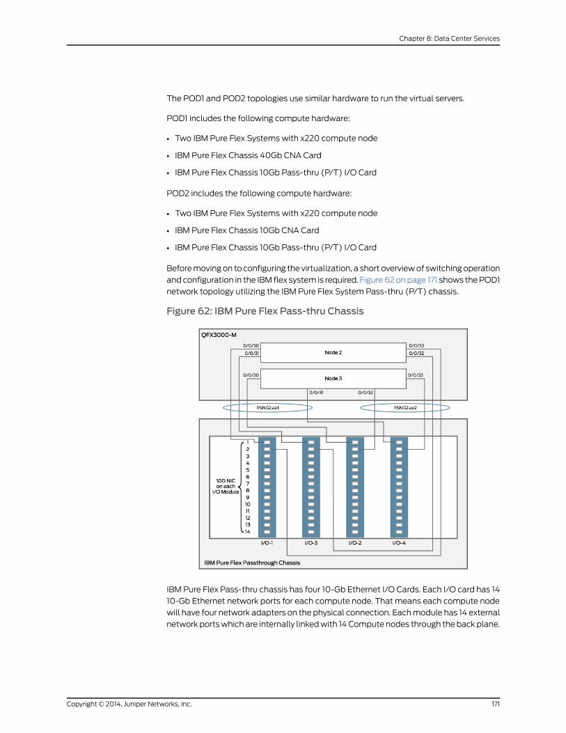
The POD1 and POD2 topologies use similar hardware to run the virtual servers.
POD1 includes the following compute hardware:
• Two IBM Pure Flex Systems with x220 compute node
• IBM Pure Flex Chassis 40Gb CNA Card
• IBM Pure Flex Chassis 10Gb Pass-thru (P/T) I/O Card
POD2 includes the following compute hardware:
• Two IBM Pure Flex Systems with x220 compute node
• IBM Pure Flex Chassis 10Gb CNA Card
• IBM Pure Flex Chassis 10Gb Pass-thru (P/T) I/O Card
Beforemovingon to configuring the virtualization, a short overviewof switchingoperation
andconfiguration in the IBM flex system is required. Figure62onpage 171 shows thePOD1
network topology utilizing the IBM Pure Flex System Pass-thru (P/T) chassis.
Figure 62: IBM Pure Flex Pass-thru Chassis
IBM Pure Flex Pass-thru chassis has four 10-Gb Ethernet I/O Cards. Each I/O card has 14
10-Gb Ethernet network ports for each compute node. That means each compute node
will have four network adapters on the physical connection. Eachmodule has 14 external
network portswhich are internally linkedwith 14Compute nodes through the back plane.
171Copyright © 2014, Juniper Networks, Inc.
Chapter 8: Data Center Services

• I/Omodule 1 of port number 1 will connect to compute node 1
• I/Omodule 2 of port number 1 will connect to compute node 1
• I/Omodule 3 of port number 1 will connect to compute node 1
• I/Omodule 4 of port number 1 will connect to compute node 1
The 14 Compute nodes have connectivity to all 4 I/Omodules, and each compute node
has 4 network ports. All four network ports are connected to different node of RSNG of
the QFX3000-MQFabric system, which gives full redundancy. Also LAG is configured
between the servers and access switches. This configuration ensures utilization of all
the links while providing full redundancy.
The next section shows a sample configuration for connection from the QFX3000-M
(POD1) and the QFX3000-M (POD2) to the two pass-thru chassis compute nodes.
Configuring POD to Pass-thru Chassis Compute Nodes
Toconfigure theconnectionbetween thePODsand thecompute role, follow these steps:
1. ConfigurePOD1 (QFabricQFX3000-M).Pleasenote that youmustuseanMTUsetting
of 9192. Enabling jumbo frames in the data center generally enables better
performance.
[edit]set interfaces interface-range IBM-FLEX-2-CN1-passthroughmember"n2:xe-0/0/[30-31]"
set interfaces interface-range IBM-FLEX-2-CN1-passthroughmember"n3:xe-0/0/[30-31]"
set interfaces interface-range IBM-FLEX-2-CN1-passthrough ether-options 802.3adRSNG2:ae1
set interfaces interface-range IBM-FLEX-2-CN2-passthroughmember"n3:xe-0/0/[32-33]"
set interfaces interface-range IBM-FLEX-2-CN2-passthroughmember"n2:xe-0/0/[32-33]"
set interfaces interface-range IBM-FLEX-2-CN2-passthrough ether-options 802.3adRSNG2:ae2
set interfaces RSNG2:ae1 description "IBM Flex-2 Passthrough-CN1"set interfaces RSNG2:ae1 unit 0 family ethernet-switching port-mode trunkset interfaces RSNG2:ae1 unit 0 family ethernet-switching vlanmembers MGMTset interfaces RSNG2:ae1 unit 0 family ethernet-switching vlanmembers Infraset interfaces RSNG2:ae1 unit 0 family ethernet-switching vlanmembers Exchangeset interfaces RSNG2:ae1 unit 0 family ethernet-switching vlanmembersWikimediaset interfaces RSNG2:ae1 unit 0 family ethernet-switching vlanmembers SQLset interfacesRSNG2:ae1unit0 familyethernet-switchingvlanmembersStorage-POD1set interfaces RSNG2:ae1 unit 0 family ethernet-switching vlanmembersExchange-Cluster
set interfaces RSNG2:ae1 unit 0 family ethernet-switching vlanmembers SharePointset interfacesRSNG2:ae1unit0 familyethernet-switchingvlanmembersSecurity-Mgmtset interfaces RSNG2:ae1 unit 0 family ethernet-switching vlanmembers Vmotionset interfaces RSNG2:ae1 unit 0 family ethernet-switching vlanmembers VM-FTset interfacesRSNG2:ae1unit0familyethernet-switchingvlanmembersRemote-Accessset interfaces RSNG2:ae2 description "IBM Flex-2 Passthrough-CN2"set interfaces RSNG2:ae2 unit 0 family ethernet-switching port-mode trunkset interfaces RSNG2:ae2 unit 0 family ethernet-switching vlanmembers MGMT
Copyright © 2014, Juniper Networks, Inc.172
MetaFabric™ Architecture Virtualized Data Center
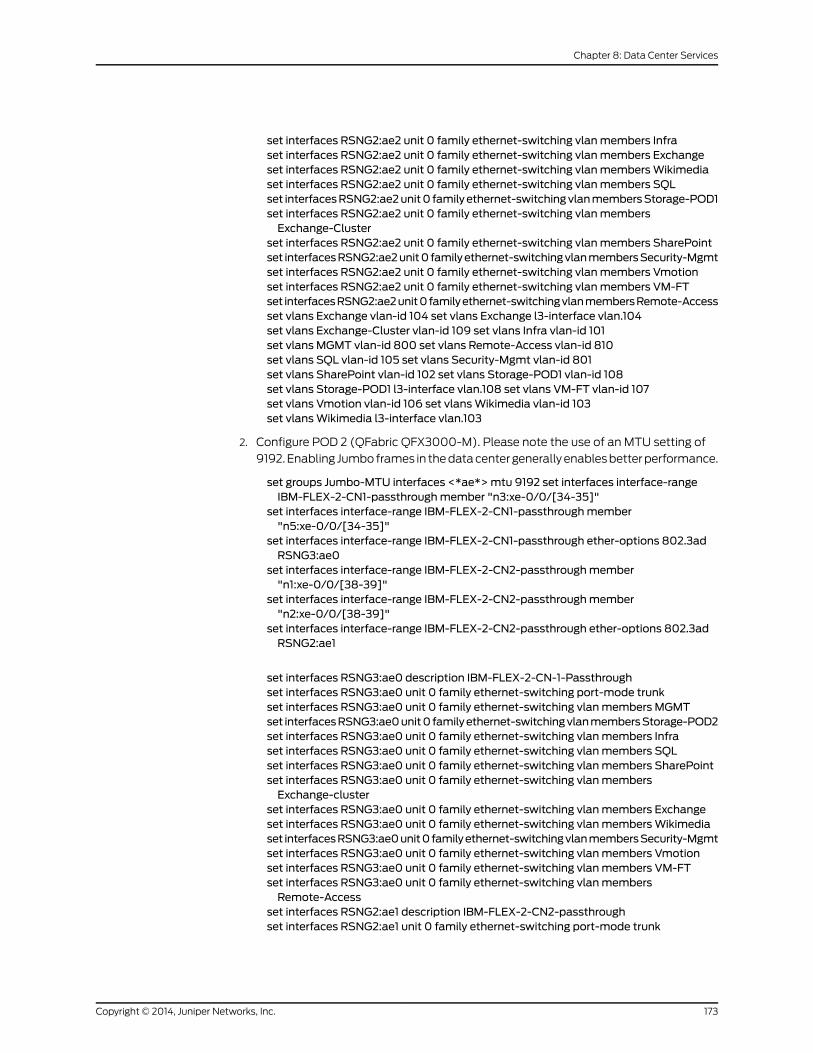
set interfaces RSNG2:ae2 unit 0 family ethernet-switching vlanmembers Infraset interfaces RSNG2:ae2 unit 0 family ethernet-switching vlanmembers Exchangeset interfaces RSNG2:ae2 unit 0 family ethernet-switching vlanmembersWikimediaset interfaces RSNG2:ae2 unit 0 family ethernet-switching vlanmembers SQLset interfacesRSNG2:ae2unit0 familyethernet-switchingvlanmembersStorage-POD1set interfaces RSNG2:ae2 unit 0 family ethernet-switching vlanmembersExchange-Cluster
set interfaces RSNG2:ae2 unit 0 family ethernet-switching vlanmembers SharePointset interfacesRSNG2:ae2unit0 familyethernet-switchingvlanmembersSecurity-Mgmtset interfaces RSNG2:ae2 unit 0 family ethernet-switching vlanmembers Vmotionset interfaces RSNG2:ae2 unit 0 family ethernet-switching vlanmembers VM-FTset interfacesRSNG2:ae2unit0familyethernet-switchingvlanmembersRemote-Accessset vlans Exchange vlan-id 104 set vlans Exchange l3-interface vlan.104set vlans Exchange-Cluster vlan-id 109 set vlans Infra vlan-id 101set vlans MGMT vlan-id 800 set vlans Remote-Access vlan-id 810set vlans SQL vlan-id 105 set vlans Security-Mgmt vlan-id 801set vlans SharePoint vlan-id 102 set vlans Storage-POD1 vlan-id 108set vlans Storage-POD1 l3-interface vlan.108 set vlans VM-FT vlan-id 107set vlans Vmotion vlan-id 106 set vlansWikimedia vlan-id 103set vlansWikimedia l3-interface vlan.103
2. Configure POD 2 (QFabric QFX3000-M). Please note the use of an MTU setting of
9192.Enabling Jumboframes in thedatacentergenerallyenablesbetterperformance.
set groups Jumbo-MTU interfaces <*ae*>mtu 9192 set interfaces interface-rangeIBM-FLEX-2-CN1-passthroughmember "n3:xe-0/0/[34-35]"
set interfaces interface-range IBM-FLEX-2-CN1-passthroughmember"n5:xe-0/0/[34-35]"
set interfaces interface-range IBM-FLEX-2-CN1-passthrough ether-options 802.3adRSNG3:ae0
set interfaces interface-range IBM-FLEX-2-CN2-passthroughmember"n1:xe-0/0/[38-39]"
set interfaces interface-range IBM-FLEX-2-CN2-passthroughmember"n2:xe-0/0/[38-39]"
set interfaces interface-range IBM-FLEX-2-CN2-passthrough ether-options 802.3adRSNG2:ae1
set interfaces RSNG3:ae0 description IBM-FLEX-2-CN-1-Passthroughset interfaces RSNG3:ae0 unit 0 family ethernet-switching port-mode trunkset interfaces RSNG3:ae0 unit 0 family ethernet-switching vlanmembers MGMTset interfacesRSNG3:ae0unit0 familyethernet-switchingvlanmembersStorage-POD2set interfaces RSNG3:ae0 unit 0 family ethernet-switching vlanmembers Infraset interfaces RSNG3:ae0 unit 0 family ethernet-switching vlanmembers SQLset interfaces RSNG3:ae0 unit 0 family ethernet-switching vlanmembers SharePointset interfaces RSNG3:ae0 unit 0 family ethernet-switching vlanmembersExchange-cluster
set interfaces RSNG3:ae0 unit 0 family ethernet-switching vlanmembers Exchangeset interfaces RSNG3:ae0 unit 0 family ethernet-switching vlanmembersWikimediaset interfacesRSNG3:ae0unit0familyethernet-switchingvlanmembersSecurity-Mgmtset interfaces RSNG3:ae0 unit 0 family ethernet-switching vlanmembers Vmotionset interfaces RSNG3:ae0 unit 0 family ethernet-switching vlanmembers VM-FTset interfaces RSNG3:ae0 unit 0 family ethernet-switching vlanmembersRemote-Access
set interfaces RSNG2:ae1 description IBM-FLEX-2-CN2-passthroughset interfaces RSNG2:ae1 unit 0 family ethernet-switching port-mode trunk
173Copyright © 2014, Juniper Networks, Inc.
Chapter 8: Data Center Services

set interfaces RSNG2:ae1 unit 0 family ethernet-switching vlanmembers MGMTset interfacesRSNG2:ae1unit0 familyethernet-switchingvlanmembersStorage-POD2set interfaces RSNG2:ae1 unit 0 family ethernet-switching vlanmembers Infraset interfaces RSNG2:ae1 unit 0 family ethernet-switching vlanmembers SQLset interfaces RSNG2:ae1 unit 0 family ethernet-switching vlanmembers SharePointset interfaces RSNG2:ae1 unit 0 family ethernet-switching vlanmembersExchange-cluster
set interfaces RSNG2:ae1 unit 0 family ethernet-switching vlanmembers Exchangeset interfaces RSNG2:ae1 unit 0 family ethernet-switching vlanmembersWikimediaset interfacesRSNG2:ae1unit0 familyethernet-switchingvlanmembersSecurity-Mgmtset interfaces RSNG2:ae1 unit 0 family ethernet-switching vlanmembers Vmotionset interfaces RSNG2:ae1 unit 0 family ethernet-switching vlanmembers VM-FTset interfacesRSNG2:ae1unit0familyethernet-switchingvlanmembersRemote-Accessset vlans Exchange vlan-id 104set vlans Exchange-cluster vlan-id 109set vlans Infra vlan-id 101set vlans MGMT vlan-id 800set vlans Remote-Access vlan-id 810set vlans SQL vlan-id 105set vlans SQL l3-interface vlan.105set vlans Security-Mgmt vlan-id 801set vlans SharePoint vlan-id 102set vlans SharePoint l3-interface vlan.102set vlans Storage-POD2 vlan-id 208set vlans Storage-POD2 l3-interface vlan.208set vlans VM-FT vlan-id 107set vlans Vmotion vlan-id 106set vlansWikimedia vlan-id 103
TheMetaFabric 1.0 solution also utilizes the 40-Gb Ethernet CNA I/Omodule (in POD1).
A short overview of the operation and configuration of this module is required.
Figure63onpage 175shows thePOD1network topologyutilizing the IBMPureFlexSystem
Chassis with the 40-Gb Ethernet CNA I/Omodule.
Copyright © 2014, Juniper Networks, Inc.174
MetaFabric™ Architecture Virtualized Data Center
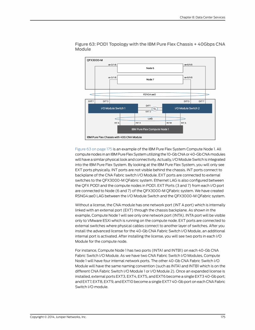
Figure 63: POD1 Topologywith the IBMPure Flex Chassis + 40Gbps CNAModule
Figure 63 on page 175 is an example of the IBM Pure Flex System Compute Node 1. All
computenodes inan IBMPureFlexSystemutilizing the 10-GbCNAor40-GbCNAmodules
will havea similar physical lookandconnectivity. Actually, I/OModuleSwitch is integrated
into the IBM Pure Flex System. By looking at the IBM Pure Flex System, you will only see
EXT ports physically. INT ports are not visible behind the chassis. INT ports connect to
backplane of the CNA Fabric switch I/O Module. EXT ports are connected to external
switches to the QFX3000-MQFabric system. Ethernet LAG is also configured between
the QFX POD1 and the compute nodes in POD1. EXT Ports (3 and 7) from each I/O port
are connected to Node (6 and 7) of the QFX3000-MQFabric system.We have created
RSNG4:ae0 LAG between the I/O Module Switch and the QFX3000-MQFabric system.
Without a license, the CNAmodule has one network port (INT A port) which is internally
linked with an external port (EXT) through the chassis backplane. As shown in the
example, Compute Node 1 will see only one network port (INTA). INTA port will be visible
only to VMware ESXi which is running on the compute node. EXT ports are connected to
external switches where physical cables connect to another layer of switches. After you
install the advanced license for the 40-Gb CNA Fabric Switch I/O Module, an additional
internal port is activated. After installing the license, you will see two ports in each I/O
Module for the compute node.
For instance, Compute Node 1 has two ports (INTA1 and INTB1) on each 40-Gb CNA
Fabric Switch I/O Module. As we have two CNA Fabric Switch I/O Modules, Compute
Node 1 will have four internal network ports. The other 40-Gb CNA Fabric Switch I/O
Module will have the same naming convention (such as INTA1 and INTB1 which is on the
different CNA Fabric Switch I/O Module 1 or I/O Module 2). Once an expanded license is
installed, external ports EXT3, EXT4, EXT5, and EXT6becomea single EXT340-Gbport;
andEXT7, EXT8, EXT9, andEXT10becomea single EXT740-Gbport on eachCNAFabric
Switch I/Omodule.
175Copyright © 2014, Juniper Networks, Inc.
Chapter 8: Data Center Services

NOTE: Simply creating RSNG between the CNA Fabric Switch andQFX3000-MQFabric system is not an effective configuration. Thisconfiguration can cause intermittent packet loss because both I/OmodulesfromtheCNAFabric switchwork independently. Intermittent packet losswillhappen if you configure LAG/RSNGonly on theQFX3000-MQFabric systemswitch. To resolve this issue, LAGmust also be configured on the CNA FabricSwitch I/Omodule.
Configuration of LAG on CNA Fabric Switches is covered below. In this solution example,
we have cross-connected the EXT1 and EXT2 ports of CNA Fabric Switch I/O Module 1
and 2. This is referred to as an ISL onCNAFabric Switches. This is themajor configuration
required to work LAG efficiently on the internal and external side. LAG is configured on
INT ports and EXT ports. This LAG is configured using the LACP protocol as a trunk port
and carrying multiple VLAN application traffic.
Configuring the CNA Fabric Switches
To configure LAG on the CNA Fabric Switches, follow these steps:
1. Configure the Fabric Switch I/O Module1 on the IBM Pure Flex System 40-Gbps CNA.
interface port INTA1taggingexit
!interface port INTA2taggingexit!interface port INTA3taggingexit
!interface port INTA4taggingexit
!interface port INTA5taggingexit
!interface port INTB1taggingexit
!interface port INTB2taggingexit
!interface port INTB3taggingexit
!
Copyright © 2014, Juniper Networks, Inc.176
MetaFabric™ Architecture Virtualized Data Center
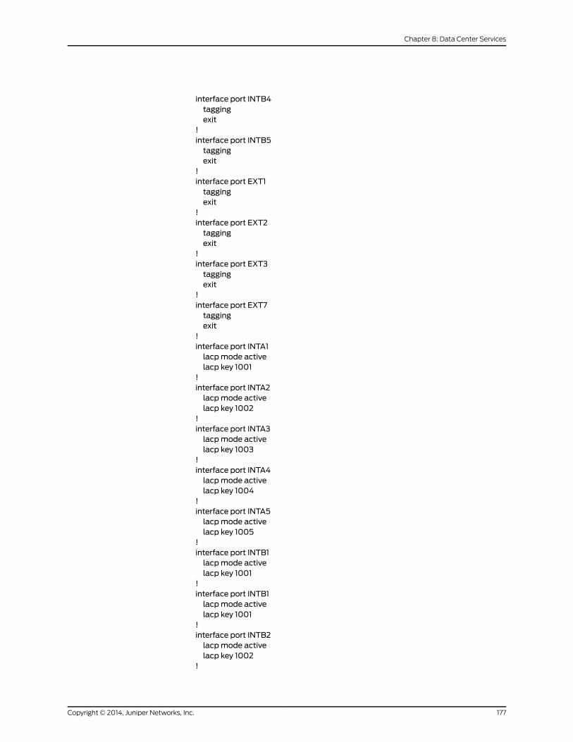
interface port INTB4taggingexit
!interface port INTB5taggingexit
!interface port EXT1taggingexit
!interface port EXT2taggingexit
!interface port EXT3taggingexit
!interface port EXT7taggingexit
!interface port INTA1lacpmode activelacp key 1001
!interface port INTA2lacpmode activelacp key 1002
!interface port INTA3lacpmode activelacp key 1003
!interface port INTA4lacpmode activelacp key 1004
!interface port INTA5lacpmode activelacp key 1005
!interface port INTB1lacpmode activelacp key 1001
!interface port INTB1lacpmode activelacp key 1001
!interface port INTB2lacpmode activelacp key 1002
!
177Copyright © 2014, Juniper Networks, Inc.
Chapter 8: Data Center Services

interface port INTB3lacpmode activelacp key 1003
!interface port INTB4lacpmode activelacp key 1004
!interface port INTB5lacpmode activelacp key 1005
!interface port EXT1lacpmode activelacp key 200
!interface port EXT2lacpmode activelacp key 200
!interface port EXT3lacpmode activelacp key 1000
!interface port EXT7lacpmode activelacp key 1000
!vlan 101enablename "INFRA"member INTA1-INTA5,INTB1-INTB5,EXT1-EXT3,EXT7
!vlan 102enablename "SharePoint"member INTA1-INTA5,INTB1-INTB5,EXT1-EXT3,EXT7
!vlan 103enablename "WM"member INTA1-INTA5,INTB1-INTB5,EXT1-EXT3,EXT7
!vlan 104enablename "EXCHANGE"member INTA1-INTA5,INTB1-INTB5,EXT1-EXT3,EXT7
!vlan 105enablename "SQL"member INTA1-INTA5,INTB1-INTB5,EXT1-EXT3,EXT7
!vlan 106enablename " Vmotion"
Copyright © 2014, Juniper Networks, Inc.178
MetaFabric™ Architecture Virtualized Data Center
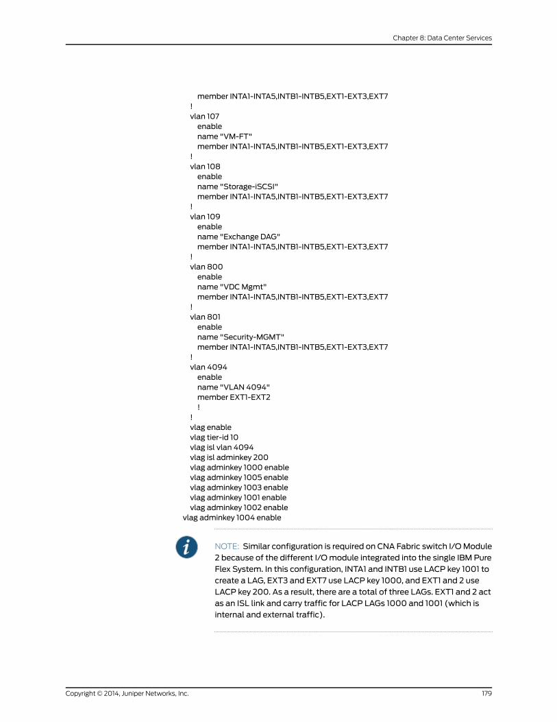
member INTA1-INTA5,INTB1-INTB5,EXT1-EXT3,EXT7!vlan 107enablename "VM-FT"member INTA1-INTA5,INTB1-INTB5,EXT1-EXT3,EXT7
!vlan 108enablename "Storage-iSCSI"member INTA1-INTA5,INTB1-INTB5,EXT1-EXT3,EXT7
!vlan 109enablename "Exchange DAG"member INTA1-INTA5,INTB1-INTB5,EXT1-EXT3,EXT7
!vlan 800enablename "VDCMgmt"member INTA1-INTA5,INTB1-INTB5,EXT1-EXT3,EXT7
!vlan 801enablename "Security-MGMT"member INTA1-INTA5,INTB1-INTB5,EXT1-EXT3,EXT7
!vlan 4094enablename "VLAN 4094"member EXT1-EXT2!
!vlag enablevlag tier-id 10vlag isl vlan 4094vlag isl adminkey 200vlag adminkey 1000 enablevlag adminkey 1005 enablevlag adminkey 1003 enablevlag adminkey 1001 enablevlag adminkey 1002 enable
vlag adminkey 1004 enable
NOTE: Similar configuration is required on CNA Fabric switch I/OModule2 because of the different I/Omodule integrated into the single IBM PureFlex System. In this configuration, INTA1 and INTB1 use LACP key 1001 tocreate a LAG, EXT3 and EXT7 use LACP key 1000, and EXT1 and 2 useLACP key 200. As a result, there are a total of three LAGs. EXT1 and 2 actas an ISL link and carry traffic for LACP LAGs 1000 and 1001 (which isinternal and external traffic).
179Copyright © 2014, Juniper Networks, Inc.
Chapter 8: Data Center Services
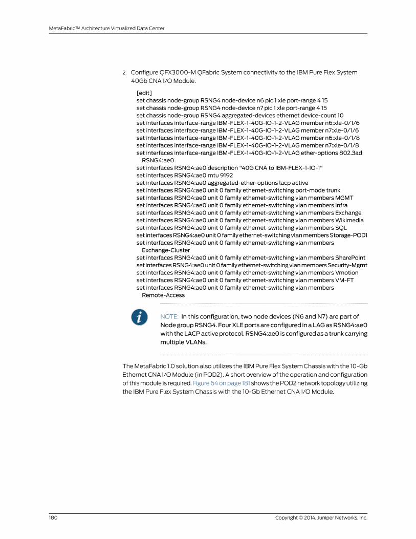
2. Configure QFX3000-MQFabric System connectivity to the IBM Pure Flex System
40Gb CNA I/OModule.
[edit]set chassis node-group RSNG4 node-device n6 pic 1 xle port-range 4 15set chassis node-group RSNG4 node-device n7 pic 1 xle port-range 4 15set chassis node-group RSNG4 aggregated-devices ethernet device-count 10set interfaces interface-range IBM-FLEX-1-40G-IO-1-2-VLAGmember n6:xle-0/1/6set interfaces interface-range IBM-FLEX-1-40G-IO-1-2-VLAGmember n7:xle-0/1/6set interfaces interface-range IBM-FLEX-1-40G-IO-1-2-VLAGmember n6:xle-0/1/8set interfaces interface-range IBM-FLEX-1-40G-IO-1-2-VLAGmember n7:xle-0/1/8set interfaces interface-range IBM-FLEX-1-40G-IO-1-2-VLAG ether-options 802.3adRSNG4:ae0
set interfaces RSNG4:ae0 description "40G CNA to IBM-FLEX-1-IO-1"set interfaces RSNG4:ae0mtu 9192set interfaces RSNG4:ae0 aggregated-ether-options lacp activeset interfaces RSNG4:ae0 unit 0 family ethernet-switching port-mode trunkset interfaces RSNG4:ae0 unit 0 family ethernet-switching vlanmembers MGMTset interfaces RSNG4:ae0 unit 0 family ethernet-switching vlanmembers Infraset interfaces RSNG4:ae0 unit 0 family ethernet-switching vlanmembers Exchangeset interfaces RSNG4:ae0 unit 0 family ethernet-switching vlanmembersWikimediaset interfaces RSNG4:ae0 unit 0 family ethernet-switching vlanmembers SQLset interfacesRSNG4:ae0unit0 familyethernet-switchingvlanmembersStorage-POD1set interfaces RSNG4:ae0 unit 0 family ethernet-switching vlanmembersExchange-Cluster
set interfaces RSNG4:ae0 unit 0 family ethernet-switching vlanmembers SharePointset interfacesRSNG4:ae0unit0familyethernet-switchingvlanmembersSecurity-Mgmtset interfaces RSNG4:ae0 unit 0 family ethernet-switching vlanmembers Vmotionset interfaces RSNG4:ae0 unit 0 family ethernet-switching vlanmembers VM-FTset interfaces RSNG4:ae0 unit 0 family ethernet-switching vlanmembersRemote-Access
NOTE: In this configuration, two node devices (N6 and N7) are part ofNodegroupRSNG4.FourXLEportsareconfigured inaLAGasRSNG4:ae0with theLACPactiveprotocol.RSNG4:ae0 isconfiguredasa trunkcarryingmultiple VLANs.
TheMetaFabric 1.0 solutionalsoutilizes the IBMPureFlexSystemChassiswith the 10-Gb
Ethernet CNA I/OModule (in POD2). A short overviewof the operation and configuration
of thismodule is required. Figure64onpage 181 shows thePOD2network topologyutilizing
the IBM Pure Flex System Chassis with the 10-Gb Ethernet CNA I/OModule.
Copyright © 2014, Juniper Networks, Inc.180
MetaFabric™ Architecture Virtualized Data Center
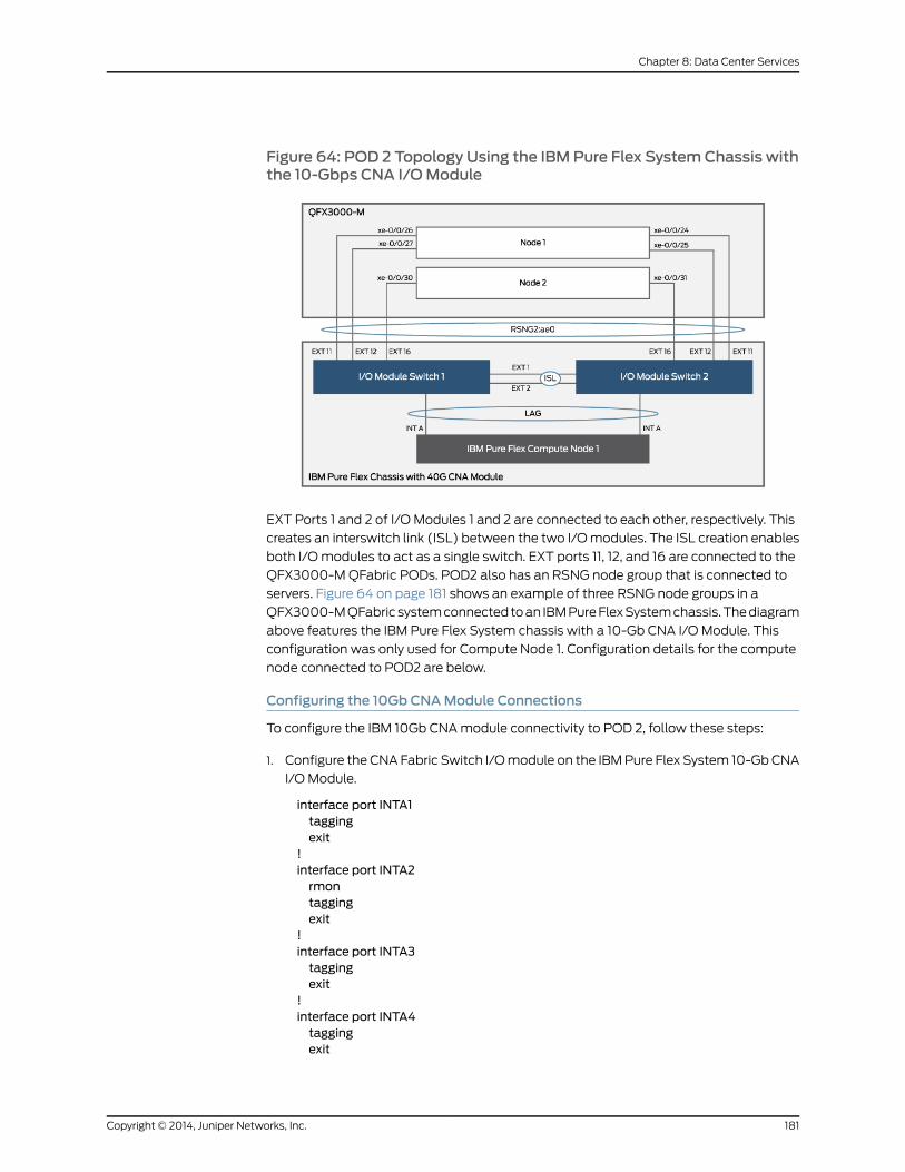
Figure 64: POD 2 Topology Using the IBM Pure Flex SystemChassis withthe 10-Gbps CNA I/OModule
EXT Ports 1 and 2 of I/O Modules 1 and 2 are connected to each other, respectively. This
creates an interswitch link (ISL) between the two I/Omodules. The ISL creation enables
both I/Omodules to act as a single switch. EXT ports 11, 12, and 16 are connected to the
QFX3000-MQFabric PODs. POD2 also has an RSNG node group that is connected to
servers. Figure 64 on page 181 shows an example of three RSNG node groups in a
QFX3000-MQFabric systemconnectedtoan IBMPureFlexSystemchassis.Thediagram
above features the IBM Pure Flex System chassis with a 10-Gb CNA I/OModule. This
configuration was only used for Compute Node 1. Configuration details for the compute
node connected to POD2 are below.
Configuring the 10Gb CNAModule Connections
To configure the IBM 10Gb CNAmodule connectivity to POD 2, follow these steps:
1. Configure the CNA Fabric Switch I/Omodule on the IBMPure Flex System 10-GbCNA
I/OModule.
interface port INTA1taggingexit
!interface port INTA2rmontaggingexit
!interface port INTA3taggingexit
!interface port INTA4taggingexit
181Copyright © 2014, Juniper Networks, Inc.
Chapter 8: Data Center Services
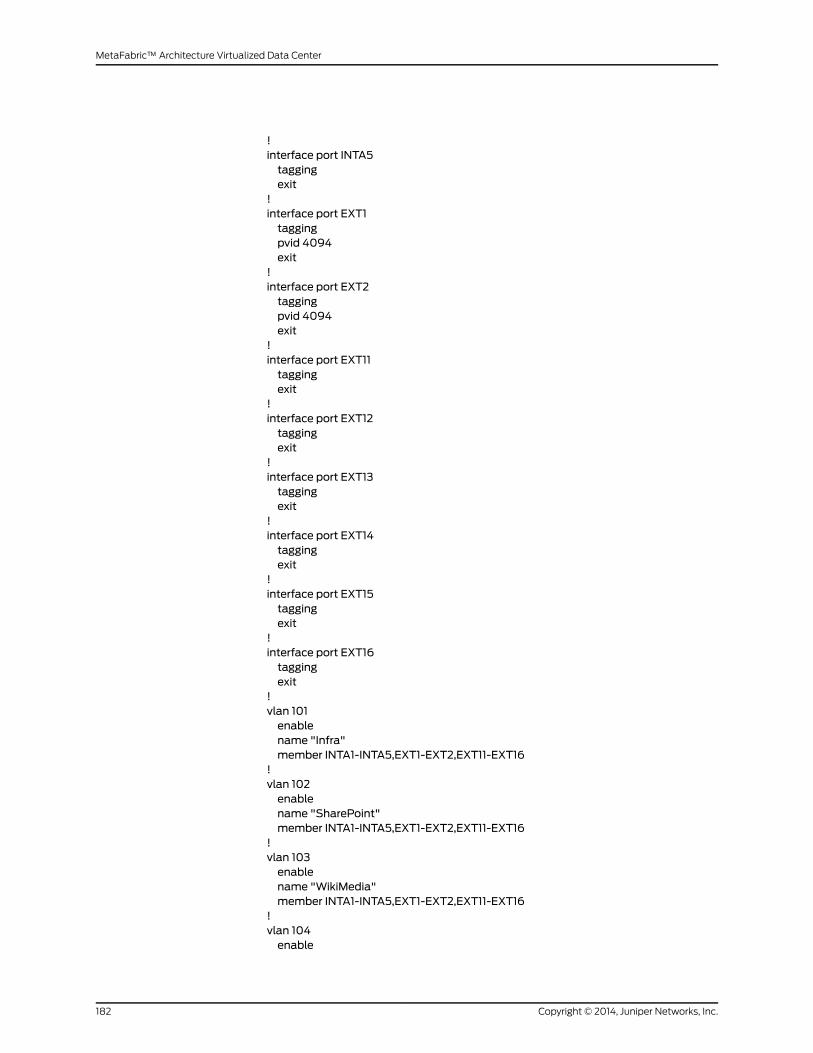
!interface port INTA5taggingexit
!interface port EXT1taggingpvid 4094exit
!interface port EXT2taggingpvid 4094exit
!interface port EXT11taggingexit
!interface port EXT12taggingexit
!interface port EXT13taggingexit
!interface port EXT14taggingexit
!interface port EXT15taggingexit
!interface port EXT16taggingexit
!vlan 101enablename "Infra"member INTA1-INTA5,EXT1-EXT2,EXT11-EXT16
!vlan 102enablename "SharePoint"member INTA1-INTA5,EXT1-EXT2,EXT11-EXT16
!vlan 103enablename "WikiMedia"member INTA1-INTA5,EXT1-EXT2,EXT11-EXT16
!vlan 104enable
Copyright © 2014, Juniper Networks, Inc.182
MetaFabric™ Architecture Virtualized Data Center
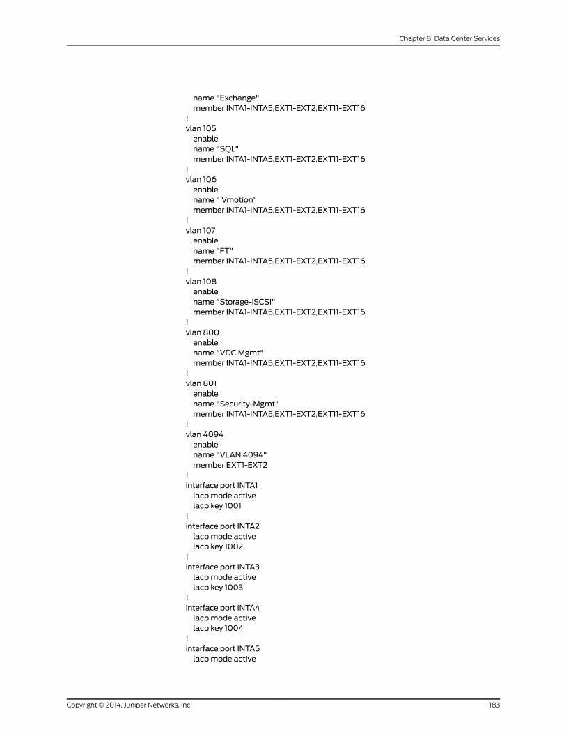
name "Exchange"member INTA1-INTA5,EXT1-EXT2,EXT11-EXT16
!vlan 105enablename "SQL"member INTA1-INTA5,EXT1-EXT2,EXT11-EXT16
!vlan 106enablename " Vmotion"member INTA1-INTA5,EXT1-EXT2,EXT11-EXT16
!vlan 107enablename "FT"member INTA1-INTA5,EXT1-EXT2,EXT11-EXT16
!vlan 108enablename "Storage-iSCSI"member INTA1-INTA5,EXT1-EXT2,EXT11-EXT16
!vlan 800enablename "VDCMgmt"member INTA1-INTA5,EXT1-EXT2,EXT11-EXT16
!vlan 801enablename "Security-Mgmt"member INTA1-INTA5,EXT1-EXT2,EXT11-EXT16
!vlan 4094enablename "VLAN 4094"member EXT1-EXT2
!interface port INTA1lacpmode activelacp key 1001
!interface port INTA2lacpmode activelacp key 1002
!interface port INTA3lacpmode activelacp key 1003
!interface port INTA4lacpmode activelacp key 1004
!interface port INTA5lacpmode active
183Copyright © 2014, Juniper Networks, Inc.
Chapter 8: Data Center Services

lacp key 1005!interface port EXT1lacpmode activelacp key 200
!interface port EXT2lacpmode activelacp key 200
!interface port EXT11lacpmode activelacp key 1000
!interface port EXT12lacpmode activelacp key 1000
!interface port EXT13lacpmode activelacp key 1000
!interface port EXT14lacpmode activelacp key 1000
!interface port EXT15lacpmode activelacp key 1000
!interface port EXT16lacpmode activelacp key 1000!!
!vlag enablevlag tier-id 10vlag isl vlan 4094vlag isl adminkey 200vlag adminkey 1000 enablevlag adminkey 1001 enablevlag adminkey 1002 enablevlag adminkey 1003 enablevlag adminkey 1004 enablevlag adminkey 1005 enable
2. Configure QFX3000-MQFabric System connectivity to the IBM Pure Flex System
10-Gb CNA I/OModule.
[edit]set interfaces interface-range IBM-FLEX-1-10G-CNA-IO-1-2-VLAGmember"n1:xe-0/0/[24-27]"
set interfaces interface-range IBM-FLEX-1-10G-CNA-IO-1-2-VLAGmember"n2:xe-0/0/[30-31]"
Copyright © 2014, Juniper Networks, Inc.184
MetaFabric™ Architecture Virtualized Data Center

set interfaces interface-range IBM-FLEX-1-10G-CNA-IO-1-2-VLAGether-options802.3adRSNG2:ae0
set interfaces RSNG2:ae0 description IBM-FLEX-1-10G-CNAset interfaces RSNG2:ae0 unit 0 family ethernet-switching port-mode trunkset interfaces RSNG2:ae0 unit 0 family ethernet-switching vlanmembers MGMTset interfacesRSNG2:ae0unit0 familyethernet-switchingvlanmembersStorage-POD2set interfaces RSNG2:ae0 unit 0 family ethernet-switching vlanmembers Infraset interfaces RSNG2:ae0 unit 0 family ethernet-switching vlanmembers SQLset interfaces RSNG2:ae0 unit 0 family ethernet-switching vlanmembers SharePointset interfaces RSNG2:ae0 unit 0 family ethernet-switching vlanmembersExchange-cluster
set interfaces RSNG2:ae0 unit 0 family ethernet-switching vlanmembers Exchangeset interfaces RSNG2:ae0 unit 0 family ethernet-switching vlanmembersWikimediaset interfacesRSNG2:ae0unit0familyethernet-switchingvlanmembersSecurity-Mgmtset interfaces RSNG2:ae0 unit 0 family ethernet-switching vlanmembers Vmotionset interfaces RSNG2:ae0 unit 0 family ethernet-switching vlanmembers VM-FTset interfaces RSNG2:ae0 unit 0 family ethernet-switching vlanmembersRemote-Access
set vlans Exchange vlan-id 104set vlans Exchange-cluster vlan-id 109set vlans Infra vlan-id 101set vlans MGMT vlan-id 800set vlans Remote-Access vlan-id 810set vlans SQL vlan-id 105set vlans SQL l3-interface vlan.105set vlans Security-Mgmt vlan-id 801set vlans SharePoint vlan-id 102set vlans SharePoint l3-interface vlan.102set vlans Storage-POD2 vlan-id 208set vlans Storage-POD2 l3-interface vlan.208set vlans VM-FT vlan-id 107set vlans Vmotion vlan-id 106set vlansWikimedia vlan-id 103
Verification
The following verification commands (with sample output) can be used to confirm the
configuration of compute and compute switching resources in the data center.
Results
1. Verify POD1 internal switch VLAN status.
POD1-Flex1-40G-IO-1> show vlan
VLAN Name Status MGT Ports---- -------------------------------- ------ --- -------------------------1 Default VLAN ena dis INTA1-INTB14 EXT1-EXT16101 INFRA ena dis INTA1-INTA5 INTB1-INTB5 EXT1-EXT3 EXT7102 SharePoint ena dis INTA1-INTA5 INTB1-INTB5 EXT1-EXT3 EXT7103 WM ena dis INTA1-INTA5 INTB1-INTB5 EXT1-EXT3 EXT7104 EXCHANGE ena dis INTA1-INTA5 INTB1-INTB5 EXT1-EXT3 EXT7105 SQL ena dis INTA1-INTA5 INTB1-INTB5
185Copyright © 2014, Juniper Networks, Inc.
Chapter 8: Data Center Services
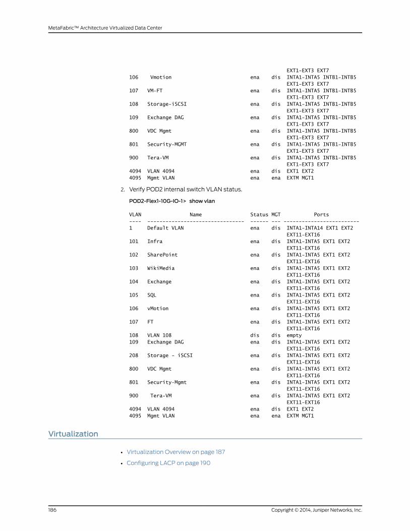
EXT1-EXT3 EXT7106 Vmotion ena dis INTA1-INTA5 INTB1-INTB5 EXT1-EXT3 EXT7107 VM-FT ena dis INTA1-INTA5 INTB1-INTB5 EXT1-EXT3 EXT7108 Storage-iSCSI ena dis INTA1-INTA5 INTB1-INTB5 EXT1-EXT3 EXT7109 Exchange DAG ena dis INTA1-INTA5 INTB1-INTB5 EXT1-EXT3 EXT7800 VDC Mgmt ena dis INTA1-INTA5 INTB1-INTB5 EXT1-EXT3 EXT7801 Security-MGMT ena dis INTA1-INTA5 INTB1-INTB5 EXT1-EXT3 EXT7900 Tera-VM ena dis INTA1-INTA5 INTB1-INTB5 EXT1-EXT3 EXT74094 VLAN 4094 ena dis EXT1 EXT24095 Mgmt VLAN ena ena EXTM MGT1
2. Verify POD2 internal switch VLAN status.
POD2-Flex1-10G-IO-1> show vlan
VLAN Name Status MGT Ports---- -------------------------------- ------ --- -------------------------1 Default VLAN ena dis INTA1-INTA14 EXT1 EXT2 EXT11-EXT16101 Infra ena dis INTA1-INTA5 EXT1 EXT2 EXT11-EXT16102 SharePoint ena dis INTA1-INTA5 EXT1 EXT2 EXT11-EXT16103 WikiMedia ena dis INTA1-INTA5 EXT1 EXT2 EXT11-EXT16104 Exchange ena dis INTA1-INTA5 EXT1 EXT2 EXT11-EXT16105 SQL ena dis INTA1-INTA5 EXT1 EXT2 EXT11-EXT16106 vMotion ena dis INTA1-INTA5 EXT1 EXT2 EXT11-EXT16107 FT ena dis INTA1-INTA5 EXT1 EXT2 EXT11-EXT16108 VLAN 108 dis dis empty109 Exchange DAG ena dis INTA1-INTA5 EXT1 EXT2 EXT11-EXT16208 Storage - iSCSI ena dis INTA1-INTA5 EXT1 EXT2 EXT11-EXT16800 VDC Mgmt ena dis INTA1-INTA5 EXT1 EXT2 EXT11-EXT16801 Security-Mgmt ena dis INTA1-INTA5 EXT1 EXT2 EXT11-EXT16900 Tera-VM ena dis INTA1-INTA5 EXT1 EXT2 EXT11-EXT164094 VLAN 4094 ena dis EXT1 EXT24095 Mgmt VLAN ena ena EXTM MGT1
Virtualization
• Virtualization Overview on page 187
• Configuring LACP on page 190
Copyright © 2014, Juniper Networks, Inc.186
MetaFabric™ Architecture Virtualized Data Center

• Configuring VMware Clusters, High Availability, and Dynamic Resource
Scheduler on page 193
• Configuring VMware Enhanced vMotion Compatibility on page 197
• Mounting Storage Using the iSCSI Protocol on page 200
• Configuring Fault Tolerance on page 201
• Configuring VMware vMotion on page 203
Virtualization Overview
In theMetaFabric 1.0 solution, all compute nodes are installed into a virtual environment
featuring the VMware ESXi 5.1 operating system. VMware ESXi provides the foundation
for building a reliable data center. VMware ESXi 5.1 is the latest hypervisor architecture
fromVMware. ESXi, vSphere client, and vCenter are components of vSphere. ESXi server
is the most important part of vSphere. ESXi is the virtualization server. All the virtual
machines or Guest OS are installed on the ESXi server.
To install, manage, and access those virtual servers which sit above the ESXi server, you
will need another part of the vSphere suite called vSphere client or vCenter. The vSphere
client allows administrators to connect to ESXi servers and access or manage virtual
machines, and is used from the clientmachine to connect to the ESXi server andperform
management tasks.
The VMware vCenter server is similar to the vSphere client, but it is a server with even
more power. The VMware vCenter server is installed on aWindows or Linux server. In this
solution, the vCenter server is installed on aWindows 2008 server that is running as a
virtual machine (VM). The VMware vCenter server is a centralizedmanagement
application that lets youmanage virtual machines and ESXi hosts centrally. VMware
vSphere client is used to access vCenter Server and ultimately manage ESXi servers
(Figure 65 on page 187). VMware vCenter server is compulsory for enterprises to have
enterprise features such as vMotion, VMwareHighAvailability, VMwareUpdateManager,
and VMware Distributed Resource Scheduler (DRS). For example, you can easily clone
an existing virtual machine by using vCenter server. vCenter is another important part of
the vSphere package.
Figure65:VMwarevSphereClientManagesvCenterServerWhich inTurnManages Virtual Machines in the Data Center
In Figure66onpage 188, all the computenodesarepart of adata center and theVMware
HA Cluster is configured on compute nodes. All compute nodes are running ESXi 5.1 OS,
which is a host operating system to all the data center VMs running business-critical
applications. With vSphere Client, you can also access ESXi hosts or the vCenter Server.
The vSphere Client is used to access the vCenter Server andmanage VMware enterprise
features.
187Copyright © 2014, Juniper Networks, Inc.
Chapter 8: Data Center Services

A vSphere Distributed Switch (VDS) functions as a single virtual switch across all
associatedhosts (Figure66onpage 188). This enables you to set network configurations
that span across all member hosts, allowing virtual machines to maintain a consistent
network configuration as they migrate across multiple hosts. Each vSphere Distributed
Switch is a network hub that virtualmachines can use. A vSphere Distributed Switch can
forward traffic internally between virtual machines or link to an external network by
connecting to physical Ethernet adapters, also known as uplink adapters. Each vSphere
DistributedSwitch can also have one ormore dvPort groups assigned to it. dvPort groups
groupmultiple ports under a common configuration and provide a stable anchor point
for virtual machines connecting to labeled networks. Each dvPort group is identified by
anetwork label,which is unique to thecurrentdata center. VLANsenablea singlephysical
LAN segment to be further segmented so that groups of ports are isolated from one
another as if theywere on physically different segments. The standard is 802.1Q. A VLAN
ID, which restricts port group traffic to a logical Ethernet segment within the physical
network, is optional.
Figure 66: VMWare vSphere Distributed Switch Topology
VMware vSphere distributed switches can be divided into two logical areas of operation:
thedataplaneand themanagementplane.Thedataplane implementspacket switching,
filtering, and tagging. Themanagementplane is thecontrol structureusedby theoperator
to configure data plane functionality from the vCenter Server. The VDS eases this
management burden by treating the network as an aggregated resource. Individual
host-level virtual switches are abstracted into one large VDS spanningmultiple hosts at
the data center level. In this design, the data plane remains local to each VDS but the
management plane is centralized.
Copyright © 2014, Juniper Networks, Inc.188
MetaFabric™ Architecture Virtualized Data Center

The first step in configuration is to create a vSphere distributed switch on a vCenter
Server. After you have created a vSphere distributed switch, youmust add hosts, create
dvPort groups, and edit vSphere distributed switch properties and policies.
With thedistributedswitch feature,VMwarevSpheresupportsprovisioning, administering,
andmonitoring of virtual networking across multiple hosts, including the following
functionalities:
• Central control of thevirtual switchport configuration, port groupnaming, filter settings,
and so on.
• LinkAggregationControlProtocol (LACP) thatnegotiatesandautomatically configures
link aggregation between vSphere hosts and access layer switches.
• Network health-check capabilities to verify vSphere with the physical network
configuration.
Additionally, the distributed switch functionality supports (Figure 66 on page 188):
• Distributed port—A port on a vSphere distributed switch that connects to a host’s
VMkernel or to a virtual machine’s network adapter.
• Distributed virtual port groups (DVPortgroups)—Port groups that specify port
configuration options for eachmember port. DVportgroups is a set of DV ports.
Configuration is inherited from dvSwitch to dvPortgroup.
• Distributed virtual uplinks (dvUplinks)—dvUplinks provide a level of abstraction for
the physical NICs (vmnics) on each host.
• PrivateVLANs(PVLANs)—PVLANsupport enablesbroader compatibilitywithexisting
networking environments using the technology.
Figure 67: VMware vSphere Distributed Switch Topology
189Copyright © 2014, Juniper Networks, Inc.
Chapter 8: Data Center Services

Figure 67 on page 189 shows an illustration of two compute nodes running ESXi 5.1 OS
with multiple VMs deployed on the ESXi hosts. Notice that two physical compute nodes
are running VMs in this topology, and the vSphere distributed switch (VDS) is virtually
extended across all ESXi hostsmanaged by the vCenter server. The configuration of VDS
is centralized to the vCenter Server.
A LAG bundle is configured between the access switches and ESXi hosts. As mentioned
in the compute node section, an RSNG configuration is required on the QFX3000-M
QFabric systems.
ESXi 5.1 supports LACP protocol for the LAG, which can be enabled by connecting the
vCenter Server Web GUI only.
NOTE: Link Aggregation Control Protocol (LACP) can only be configured viathe vSphereWeb Client.
Configuring LACP
To enable or disable LACP on an uplink port group:
NOTE: All port groups using the Uplink Port Group enabled with LACPmusthave the load-balancing policy set to IP hash load balancing, network failuredetection policy set to link status only, and all uplinks set to active.
1. Log in to the vCenter Server Web on port 9443.
Figure 68: Log In to vCenter Server
2. Select vCenter under the Home radio button from the left tab.
Copyright © 2014, Juniper Networks, Inc.190
MetaFabric™ Architecture Virtualized Data Center
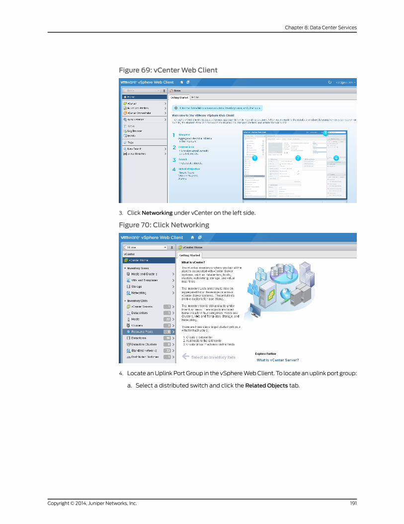
Figure 69: vCenterWeb Client
3. Click Networking under vCenter on the left side.
Figure 70: Click Networking
4. Locate anUplinkPortGroup in the vSphereWebClient. To locate anuplink port group:
a. Select a distributed switch and click the Related Objects tab.
191Copyright © 2014, Juniper Networks, Inc.
Chapter 8: Data Center Services

Figure 71: Click Related Objects
b. Click Uplink Port Groups and select an uplink port group from the list.
Figure 72: Click Uplink Ports and Select a Port
5. Select the dvSwitch-DVUplinks and click settings from the Actions tab.
6. Click Edit.
7. In the LACP section, use the drop-down box to enable or disable LACP.
Figure 73: Enable LACPMode
8. When you enable LACP, a Mode drop-downmenu appears with these options:
• Active—The port is in an active negotiating state, in which the port initiates
negotiations with remote ports by sending LACP packets.
Copyright © 2014, Juniper Networks, Inc.192
MetaFabric™ Architecture Virtualized Data Center

• Passive—The port is in a passive negotiating state, in which the port responds to
LACP packets it receives but does not initiate LACP negotiation.
Set this option to passive (disable) or active (enable). The default setting is passive.
NOTE: Step 8 is optional.
9. ClickOK.
Configuring VMware Clusters, High Availability, and Dynamic Resource Scheduler
VMware clusters enable the management of multiple host systems as a single, logical
entity, combining standalone hosts into a single virtual devicewith pooled resources and
higher availability. VMware clusters aggregate the hardware resources of individual ESX
Server hosts but manage the resources as if they resided on a single host. Now, when
you power on a virtual machine, it can be given resources from anywhere in the cluster,
rather than from a specific physical ESXi host.
VMware high availability (HA) allows virtual machines running on specific hosts to be
restartedautomatically usingother host resources in the cluster in the caseof host failure.
VMware HA continuously monitors all ESX Server hosts in a cluster and detects failures.
The VMware HA agent placed on each host maintains a heartbeat with the other hosts
in the cluster. Each server sends heartbeats to theother servers in the cluster at 5-second
intervals. If any servers loseheartbeatover three consecutiveheartbeat intervals, VMware
HA initiates the failover action of restarting all affected virtual machines on other hosts.
VMware HA also monitors whether sufficient resources are available in the cluster at all
times in order to be able to restart virtual machines on different physical host machines
in theevent of host failure. Safe restart of virtualmachines ismadepossibleby the locking
technology in the ESX Server storage stack, which allowsmultiple ESX Server hosts to
have simultaneous access to the same virtual machine files.
VMwareDynamicResourceScheduler (DRS)automaticallyprovides initial virtualmachine
placementandmakesautomatic resource relocationandoptimizationdecisionsashosts
are added or removed from the cluster. DRS also optimizes based on virtual machine
load, managing resources in events where the load on individual virtual machines goes
up or down. VMware DRS also makes cluster-wide resource pools possible.
For more information on configuration of VMware HA clusters, see:
VMware vSphere 5.1 HA Documentation
TheMetaFabric 1.0 solution utilized VMware clusters in both POD1 and POD2. Below are
overview screenshots that illustrate the use of clusters in the solution.
TheMetaFabric 1.0 solution test bedcontains three clusters: Infra (Figure 74onpage 194),
POD1(Figure75onpage 194),andPOD2(Figure76onpage 194).All clustersareconfigured
with HA and DRS.
193Copyright © 2014, Juniper Networks, Inc.
Chapter 8: Data Center Services
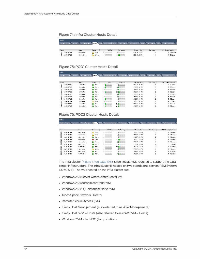
Figure 74: Infra Cluster Hosts Detail
Figure 75: POD1 Cluster Hosts Detail
Figure 76: POD2 Cluster Hosts Detail
The Infra cluster (Figure 77 on page 195) is running all VMs required to support the data
center infrastructure. The Infra cluster is hosted on two standalone servers (IBM System
x3750M4). The VMs hosted on the Infra cluster are:
• Windows 2K8 Server with vCenter Server VM
• Windows 2K8 domain controller VM
• Windows 2K8 SQL database server VM
• Junos Space Network Director
• Remote Secure Access (SA)
• Firefly Host Management (also referred to as vGWManagement)
• Firefly Host SVM – Hosts (also referred to as vGWSVM – Hosts)
• Windows 7 VM - For NOC (Jump station)
Copyright © 2014, Juniper Networks, Inc.194
MetaFabric™ Architecture Virtualized Data Center

Figure 77: INFRA Cluster VMs
The POD1 cluster (Figure 78 on page 196) hosts the VMs that run all enterprise
business-critical application in the test bed. POD1 is hosted on one IBM Flex pass-thru
chassis and one 40-Gb CNAmodule chassis. POD1 contains the following
applications/VMs:
• Windows Server 2012 domain controller
• Exchange Server 2012 CAS
• Exchange Server 2012 CAS
• Exchange Server 2012 CAS
• Exchange Mailbox server
• Exchange Mailbox server
• Exchange Mailbox server
• MediaWiki Server
• vGWSVM - All compute nodes
195Copyright © 2014, Juniper Networks, Inc.
Chapter 8: Data Center Services
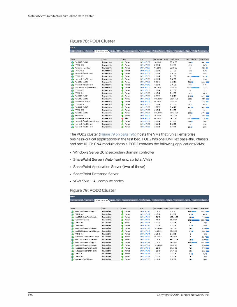
Figure 78: POD1 Cluster
The POD2 cluster (Figure 79 on page 196) hosts the VMs that run all enterprise
business-critical applications in the test bed. POD2 has one IBM Flex pass-thru chassis
and one 10-Gb CNAmodule chassis. POD2 contains the following applications/VMs:
• Windows Server 2012 secondary domain controller
• SharePoint Server (Web-front end, six total VMs)
• SharePoint Application Server (two of these)
• SharePoint Database Server
• vGWSVM – All compute nodes
Figure 79: POD2 Cluster
Copyright © 2014, Juniper Networks, Inc.196
MetaFabric™ Architecture Virtualized Data Center

Configuring VMware Enhanced vMotion Compatibility
VMware Enhanced vMotion Compatibility (EVC) configures a cluster and its hosts to
maximize vMotion compatibility. Once enabled, EVC will ensure that only hosts that are
compatible with those in the cluster can be added to the cluster. This solution uses the
Intel Sandy Bridge Generation option for enhanced vMotion compatibility that supports
the baseline feature set.
To configure a vSphere distributed switch on a vCenter server, perform following steps.
• Add a vSphere distributed switch
• Add hosts to a vSphere distributed switch
• Add a distributed port group (dvPG) configuration
For more details on configuration of VMware EVC, see:
VMware vSphere 5.1 Documentation - Enable EVC on an Existing Cluster
In the MetaFabric 1.0 solution, EVC is configured as directed in the link provided. A short
overview of the configuration follows.
Each ESXi host in the POD hosts multiple VMs and is part of a different port group. VMs
running on the PODs include Microsoft Exchange, MediaWiki, Microsoft SharePoint,
MySQL database, and Firefly Host (VM security). Because traffic is flowing to and from
many different VMs, multiple port groups are defined on the distributed switch:
• Infra = PG-INFRA-101
• SharePoint = PG-SP-102
• MediaWiki = PG-WM-103
• Exchange = PG-XCHG-104
• MySQL Database for SharePoint = PG-SQL-105
• vMotion = PG-vMotion-106
• Fault Tolerance = PG-Fault Tolerance-107
• Exchange Cluster = PG-Exchange-Cluster-109
• iSCSI POD1 = PG-STORAGE-108
• iSCSI POD2 = PG-STORAGE-208
• Network MGMT = PG-MGMT-800
• Security (vGW) = PG-Security-801
• Remote Access = PG-Remote-Access-810
These port groups are configured as shown in Figure 80 on page 198. In this scenario, a
port group naming convention was used to ease identification andmapping of VM and
its function (for example, Exchange, SharePoint) to a VLAN ID. For instance, one VM is
connected to PG104 running an Exchange application while another VM is is connected
197Copyright © 2014, Juniper Networks, Inc.
Chapter 8: Data Center Services

to PG103 running a MediaWiki application on the same ESXi host. Port group naming
convention is also used in this scenario to identify theVLAN ID towhich the host belongs.
For instance, PG-XCHG-104 is using VLAN ID 104 on the network. (The 104 in the name
is the same as the host VLAN ID.) The use of different port groups and VLANs enables
the use of vMotion, which in turn enables fault tolerance in the data center.
Figure 80: Port Groups
NIC teaming is also deployed in the solution. NIC teaming is a configuration of multiple
uplink adapters that connect to a single switch to form a team. A NIC team can either
share the load of traffic between physical and virtual networks among some or all of its
members, or provide passive failover in the event of a hardware failure or a network
outage. All the port groups (PG) except for iSCSI protocol storage groups are configured
with a NIC teaming policy for failover and redundancy. All the compute nodes have four
active adapters as dvUplink in the NIC teaming policy. This configuration enables load
balancing and resiliency. The IBM Pure Flex Systemwith a 10-Gb CNA card has two
network adapters on each ESXi host. Consequently, that system has only two dvUplink
adaptersperESXihost. Figure81onpage 199 isanexampleofoneportgroupconfiguration.
Other port groups are configured similarly (with the exception being the storage port
group).
Copyright © 2014, Juniper Networks, Inc.198
MetaFabric™ Architecture Virtualized Data Center
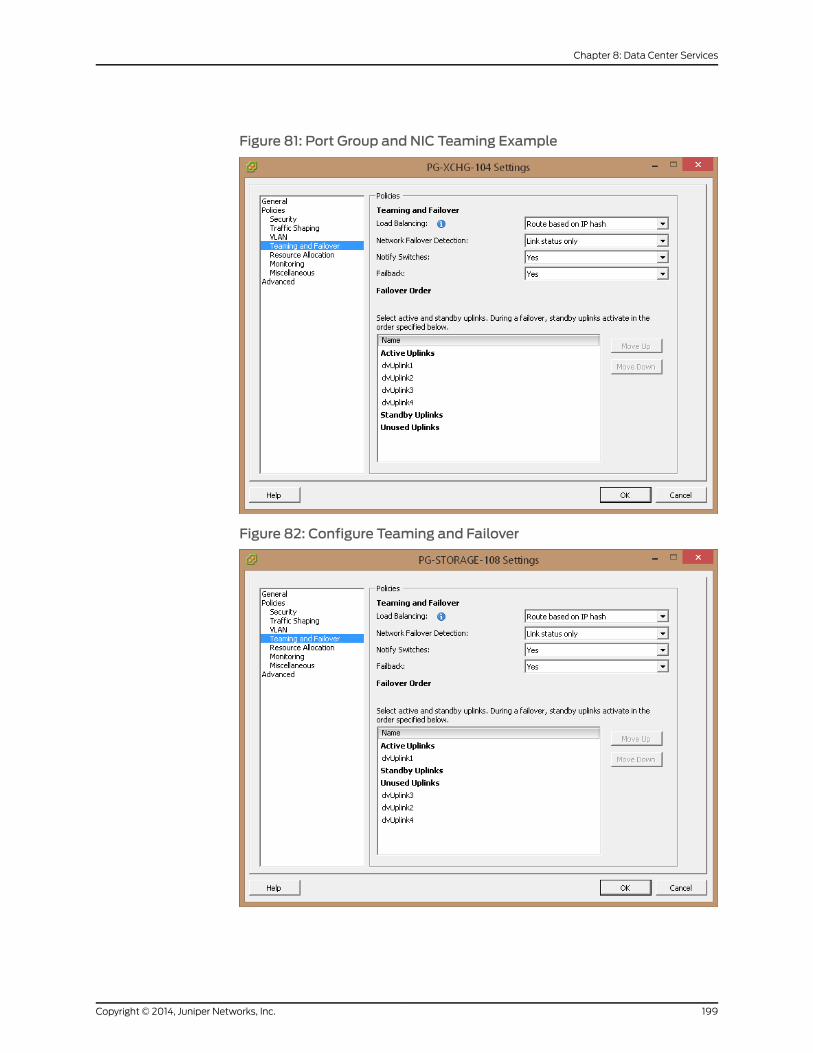
Figure 81: Port Group and NIC Teaming Example
Figure 82: Configure Teaming and Failover
199Copyright © 2014, Juniper Networks, Inc.
Chapter 8: Data Center Services
NOTE: An exception to the use of NIC teaming is an iSCSI port group. TheISCSI protocol doesn’t support multi-channeling or bundling (LAG). Whendeploying iSCSI, insteadofconfiguring fouractivedvUplinks, asingledvUplinkshould be used. In this solution, QFX3000-MQFabric POD1 uses one portgroup (PG-storage-108) and QFX3000-MQFabric POD2 uses another portgroup (PG-storage-208). These port groups are connected to the storagearray utilizing the iSCSI protocol. Figure 82 on page 199 shows the iSCSI portgroup (PG-storage-108). Port group storage 208 is configured in the sameway.
TheVMkernel TCP/IPnetworking stack supports iSCSI, NFS, vMotion, and fault tolerance
logging. The VMkernel port enables these services on the ESX server. Virtual machines
run their own system TCP/IP stacks and connect to the VMkernel at the Ethernet level
through standard and distributed switches. In ESXi, the VMkernel networking interface
provides network connectivity for the ESXi host and handles vMotion and IP storage.
Moving a virtual machine from one host to another is calledmigration. VMware vMotion
enables the migration of active virtual machines with no down time.
Management of iSCSI, vMotion, and fault tolerance is enabled by the creation of four
virtual kernel adapters. These adapters are bound to their respective distributed port
group. Formore informationoncreatingandbinding virtual kernel adapters todistributed
port groups, see:
http://pubs.vmware.com/vsphere-51/index.jsp#com.vmware.vsphere.networking.doc/GUID-59DFD949-A860-4605-A668-F63054204654.html
Mounting Storage Using the iSCSI Protocol
Tomount the storage using iSCSI protocol, perform following steps:
• Create a single VMkernel adapter for iSCSI.
• Change the port group policy for the iSCSI VMkernel adapter.
• Bind iSCSI adapters with VMkernel adapters.
• Set up Jumbo frames with iSCSI.
• Configure dynamic discovery addresses for iSCSI adapters.
• Re-scan storage on iSCSI adapters.
NOTE: The ESXi hostmust have permission to access the storage array. Thisis discussed further in the storage section of this guide.
For informationaboutconfiguringandmountingof iSCSI storageconnection toavSwitch
(either vSwitch or distributed switch), see:
Configuring and Troubleshooting iSCSI Storage
Copyright © 2014, Juniper Networks, Inc.200
MetaFabric™ Architecture Virtualized Data Center
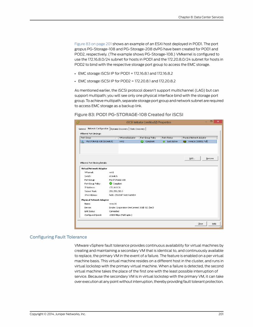
Figure 83 on page 201 shows an example of an ESXi host deployed in POD1. The port
gropus PG-Storage-108 and PG-Storage-208 dvPG have been created for POD1 and
POD2, respectively. (The example shows PG-Storage-108.) VMkernel is configured to
use the 172.16.8.0/24 subnet for hosts in POD1 and the 172.20.8.0/24 subnet for hosts in
POD2 to bind with the respective storage port group to access the EMC storage.
• EMC storage iSCSI IP for POD1 = 172.16.8.1 and 172.16.8.2
• EMC storage iSCSI IP for POD2 = 172.20.8.1 and 172.20.8.2
As mentioned earlier, the iSCSI protocol doesn’t support multichannel (LAG) but can
support multipath; you will see only one physical interface bind with the storage port
group.Toachievemultipath, separate storageport groupandnetwork subnetare required
to access EMC storage as a backup link.
Figure 83: POD1 PG-STORAGE-108 Created for iSCSI
Configuring Fault Tolerance
VMware vSphere fault tolerance provides continuous availability for virtual machines by
creating andmaintaining a secondary VM that is identical to, and continuously available
to replace, the primary VM in the event of a failure. The feature is enabled on a per virtual
machine basis. This virtual machine resides on a different host in the cluster, and runs in
virtual lockstep with the primary virtual machine. When a failure is detected, the second
virtual machine takes the place of the first one with the least possible interruption of
service. Because the secondary VM is in virtual lockstep with the primary VM, it can take
overexecutionatanypointwithout interruption, therebyproviding fault tolerantprotection.
201Copyright © 2014, Juniper Networks, Inc.
Chapter 8: Data Center Services

Figure 84: VMware Fault Tolerance
TheprimaryandsecondaryVMscontinuouslyexchangeheartbeats. This exchangeallows
thevirtualmachinepair tomonitor the statusofoneanother toensure that fault tolerance
is continually maintained. A transparent failover occurs if the host running the primary
VM fails, inwhich case the secondary VM is immediately activated to replace the primary
VM. A new secondary VM is started and fault tolerance redundancy is reestablished
within a few seconds. If the host running the secondary VM fails, it is also immediately
replaced. In either case, users experience no interruption in service and no loss of data.
VMware vSphere HAmust be enabled before you can power on fault tolerant virtual
machines or add a host to a cluster that already supports fault tolerant virtualmachines.
Only virtual machines with a single vCPU are compatible with fault tolerance.
For configuration instructions for VMware fault tolerance, see:
Preparing Your Cluster and Hosts for Fault Tolerance
The MetaFabric 1.0 solution test bed features VMware fault tolerance
(Figure85onpage202).Thiswas testedaspartof thesolutionon theportgroup“PG-Fault
tolerance-107”. VMkernel is bound to this port group. Once fault tolerance is enabled on
a VM, a secondary VM is automatically created.
Fault tolerance is also enabled onWindows domain controller VM (running on one
compute node in the POD1 cluster).
Figure 85: VMware Fault Tolerance on POD1
Copyright © 2014, Juniper Networks, Inc.202
MetaFabric™ Architecture Virtualized Data Center
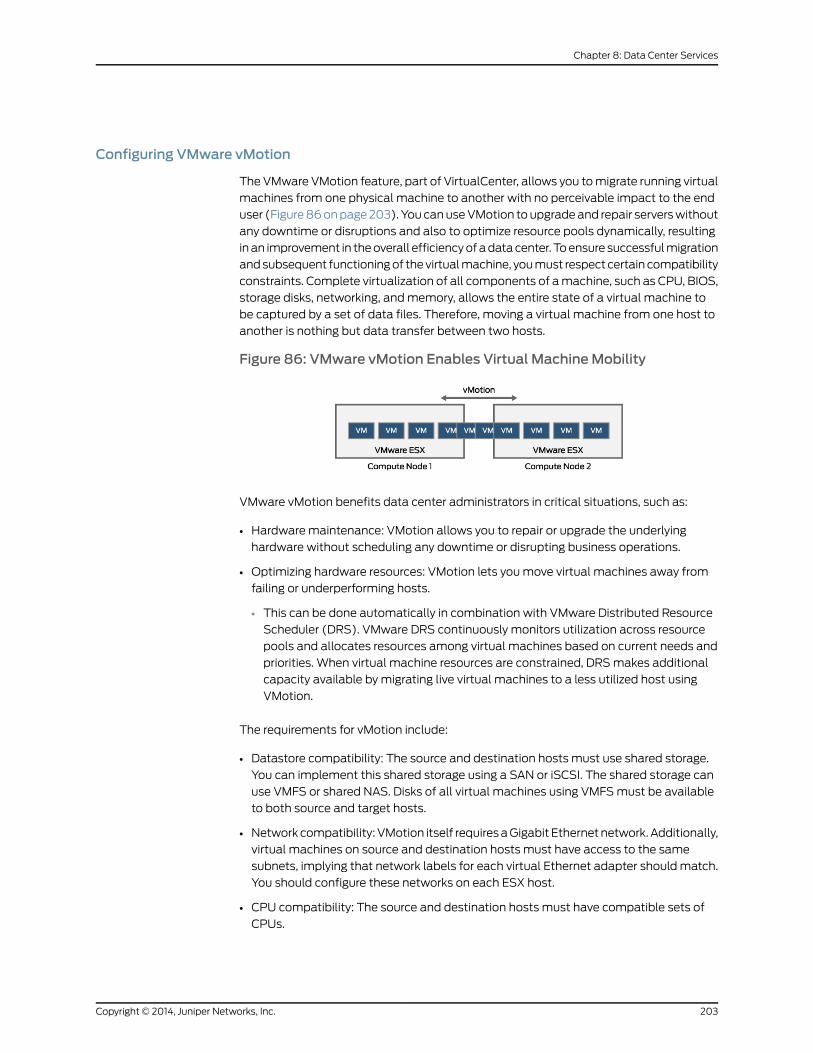
Configuring VMware vMotion
The VMware VMotion feature, part of VirtualCenter, allows you tomigrate running virtual
machines from one physical machine to another with no perceivable impact to the end
user (Figure86onpage203). YoucanuseVMotion toupgradeand repair serverswithout
any downtime or disruptions and also to optimize resource pools dynamically, resulting
inan improvement in theoverall efficiencyofadatacenter. Toensure successfulmigration
andsubsequent functioningof thevirtualmachine, youmust respect certain compatibility
constraints. Complete virtualization of all components of amachine, such as CPU, BIOS,
storage disks, networking, andmemory, allows the entire state of a virtual machine to
be captured by a set of data files. Therefore, moving a virtual machine from one host to
another is nothing but data transfer between two hosts.
Figure 86: VMware vMotion Enables Virtual MachineMobility
VMware vMotion benefits data center administrators in critical situations, such as:
• Hardware maintenance: VMotion allows you to repair or upgrade the underlying
hardware without scheduling any downtime or disrupting business operations.
• Optimizing hardware resources: VMotion lets youmove virtual machines away from
failing or underperforming hosts.
• This can be done automatically in combination with VMware Distributed Resource
Scheduler (DRS). VMware DRS continuously monitors utilization across resource
pools and allocates resources among virtual machines based on current needs and
priorities. When virtual machine resources are constrained, DRSmakes additional
capacity available by migrating live virtual machines to a less utilized host using
VMotion.
The requirements for vMotion include:
• Datastore compatibility: The source and destination hosts must use shared storage.
You can implement this shared storage using a SAN or iSCSI. The shared storage can
use VMFS or shared NAS. Disks of all virtual machines using VMFSmust be available
to both source and target hosts.
• Network compatibility: VMotion itself requiresaGigabit Ethernetnetwork.Additionally,
virtual machines on source and destination hosts must have access to the same
subnets, implying that network labels for each virtual Ethernet adapter shouldmatch.
You should configure these networks on each ESX host.
• CPU compatibility: The source and destination hosts must have compatible sets of
CPUs.
203Copyright © 2014, Juniper Networks, Inc.
Chapter 8: Data Center Services
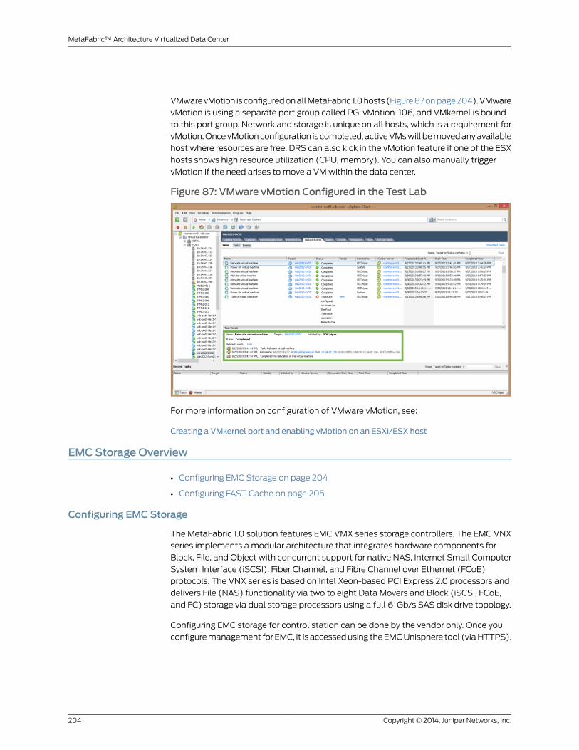
VMwarevMotion isconfiguredonallMetaFabric 1.0hosts (Figure87onpage204).VMware
vMotion is using a separate port group called PG-vMotion-106, and VMkernel is bound
to this port group. Network and storage is unique on all hosts, which is a requirement for
vMotion.OncevMotionconfiguration is completed, activeVMswill bemovedanyavailable
host where resources are free. DRS can also kick in the vMotion feature if one of the ESX
hosts shows high resource utilization (CPU, memory). You can also manually trigger
vMotion if the need arises to move a VMwithin the data center.
Figure 87: VMware vMotion Configured in the Test Lab
For more information on configuration of VMware vMotion, see:
Creating a VMkernel port and enabling vMotion on an ESXi/ESX host
EMC Storage Overview
• Configuring EMC Storage on page 204
• Configuring FAST Cache on page 205
Configuring EMC Storage
The MetaFabric 1.0 solution features EMC VMX series storage controllers. The EMC VNX
series implements a modular architecture that integrates hardware components for
Block, File, and Object with concurrent support for native NAS, Internet Small Computer
System Interface (iSCSI), Fiber Channel, and Fibre Channel over Ethernet (FCoE)
protocols. The VNX series is based on Intel Xeon-based PCI Express 2.0 processors and
delivers File (NAS) functionality via two to eight Data Movers and Block (iSCSI, FCoE,
and FC) storage via dual storage processors using a full 6-Gb/s SAS disk drive topology.
Configuring EMC storage for control station can be done by the vendor only. Once you
configuremanagement for EMC, it is accessedusing theEMCUnisphere tool (viaHTTPS).
Copyright © 2014, Juniper Networks, Inc.204
MetaFabric™ Architecture Virtualized Data Center

Configuring EMC FAST Cache
The solution was tested with EMC Fully Automated Storage Tiering (FAST) Cache. A
caching tier is a large capacity secondary cache using enterprise flash drives positioned
between the storage processor’s DRAM-based primary cache and hard disk drives. This
feature is calledFASTCache.At a system level, FASTCachehelpsmake themost efficient
use of flash drive capacity. FAST Cache does this by using flash drives for the most
frequently accessed data in the storage system instead of dedicating flash drives to a
particular application. FAST Caches are also enabled on storage pools and allow you to
leverage the lower response timeandbetter IOPSof flash driveswithout dedicating flash
drives to a specific application. Because of this implementation, flash drives need not be
dedicated to specific applications. Instead, their performance is leveraged in the caching
tier, improving performance for any application accessing the storage array. FAST Cache
adjusts to a hot spot anywhere in the array so you no longer need to analyze specific
application requirements. It providesbetter performance toall applications in the storage
systems while using fewer dedicated flash drives. A set of flash drives is selected either
automatically by the storage system or manually by the user. By default, after you have
installed the FAST Cache enabler, FAST cache is enabled on new RAID group LUNs and
storage pools. When a FAST cache has been created, the storage system automatically
promotes frequently accessed chunks of data to the FAST cache to improve application
performance.
Configuring FAST Cache
To create a FAST Cache, click the FAST Cache tab in the Storage System Properties
window to view FASTCache information (Figure 88 on page 205). If the FASTCache has
not been created on the storage system, the Create button in the bottom of the dialog
box is enabled. The Destroy button is enabled when the FAST Cache has been created.
Fast Cache is enabled on EMC VNX5500 storage.
Figure88:EMCFASTCacheConfiguration(SelectSystem,thenPropertiesin the Drop-Down)
FAST Cache can be created in certain configurations, depending on the storage system
model, and number and size of flash drives installed in the storage system. These criteria
are used to present you with the available options for your configuration. For example,
205Copyright © 2014, Juniper Networks, Inc.
Chapter 8: Data Center Services
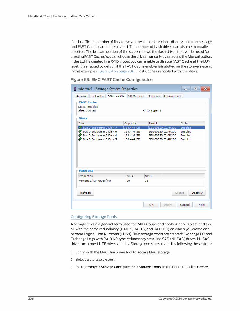
if an insufficient numberof flashdrivesareavailable,Unispheredisplaysanerrormessage
and FAST Cache cannot be created. The number of flash drives can also bemanually
selected. The bottom portion of the screen shows the flash drives that will be used for
creatingFASTCache.Youcanchoose thedrivesmanuallybyselecting theManualoption.
If the LUN is created in a RAID group, you can enable or disable FAST Cache at the LUN
level. It is enabled by default if the FASTCache enabler is installed on the storage system.
In this example (Figure 89 on page 206), Fast Cache is enabled with four disks.
Figure 89: EMC FAST Cache Configuration
Configuring Storage Pools
A storage pool is a general term used for RAID groups and pools. A pool is a set of disks,
all with the same redundancy (RAID 5, RAID 6, and RAID 1/0) on which you create one
or more Logical Unit Numbers (LUNs). Two storage pools are created: Exchange DB and
Exchange Logs with RAID 1/0 type redundancy near-line SAS (NL SAS) drives. NL SAS
drives are almost 1-TBdrive capacity. Storage pools are created by following these steps:
1. Log in with the EMC Unisphere tool to access EMC storage.
2. Select a storage system.
3. Go to Storage >Storage Configuration >Storage Pools. In the Pools tab, click Create.
Copyright © 2014, Juniper Networks, Inc.206
MetaFabric™ Architecture Virtualized Data Center
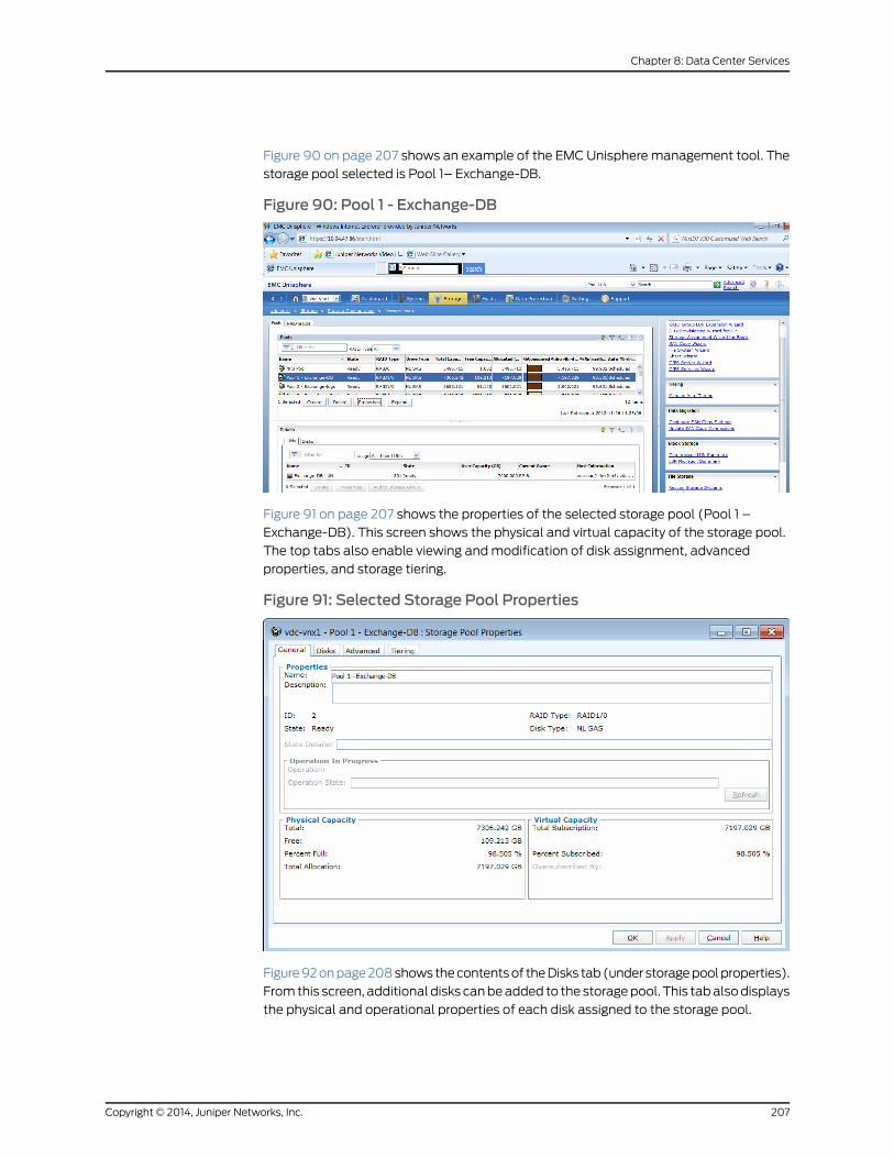
Figure 90 on page 207 shows an example of the EMC Unisphere management tool. The
storage pool selected is Pool 1– Exchange-DB.
Figure 90: Pool 1 - Exchange-DB
Figure 91 on page 207 shows the properties of the selected storage pool (Pool 1 –
Exchange-DB). This screen shows the physical and virtual capacity of the storage pool.
The top tabs also enable viewing andmodification of disk assignment, advanced
properties, and storage tiering.
Figure 91: Selected Storage Pool Properties
Figure92onpage208showsthecontentsof theDisks tab(under storagepoolproperties).
Fromthis screen, additional disks canbeadded to the storagepool. This tabalsodisplays
the physical and operational properties of each disk assigned to the storage pool.
207Copyright © 2014, Juniper Networks, Inc.
Chapter 8: Data Center Services
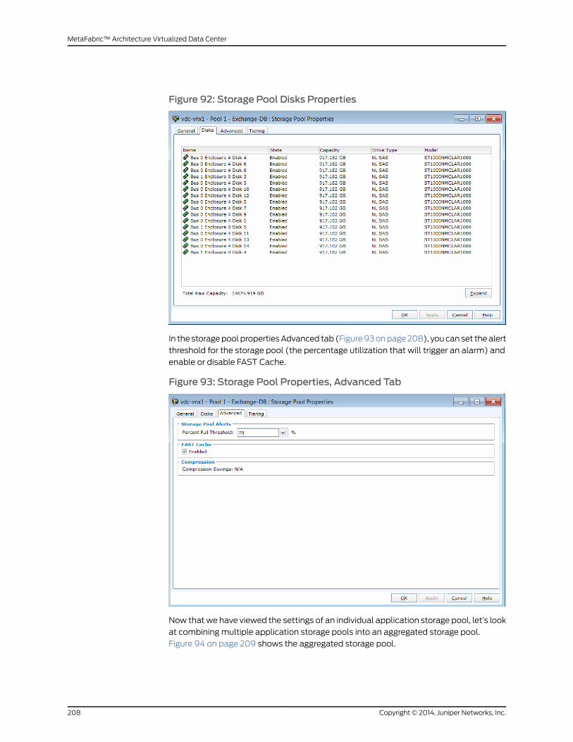
Figure 92: Storage Pool Disks Properties
In the storagepool propertiesAdvanced tab (Figure93onpage208), youcanset thealert
threshold for the storage pool (the percentage utilization that will trigger an alarm) and
enable or disable FAST Cache.
Figure 93: Storage Pool Properties, Advanced Tab
Now thatwe have viewed the settings of an individual application storage pool, let’s look
at combining multiple application storage pools into an aggregated storage pool.
Figure 94 on page 209 shows the aggregated storage pool.
Copyright © 2014, Juniper Networks, Inc.208
MetaFabric™ Architecture Virtualized Data Center
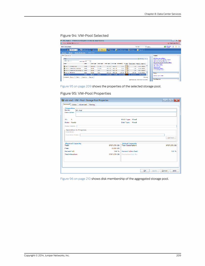
Figure 94: VM-Pool Selected
Figure 95 on page 209 shows the properties of the selected storage pool.
Figure 95: VM-Pool Properties
Figure 96 on page 210 shows disk membership of the aggregated storage pool.
209Copyright © 2014, Juniper Networks, Inc.
Chapter 8: Data Center Services
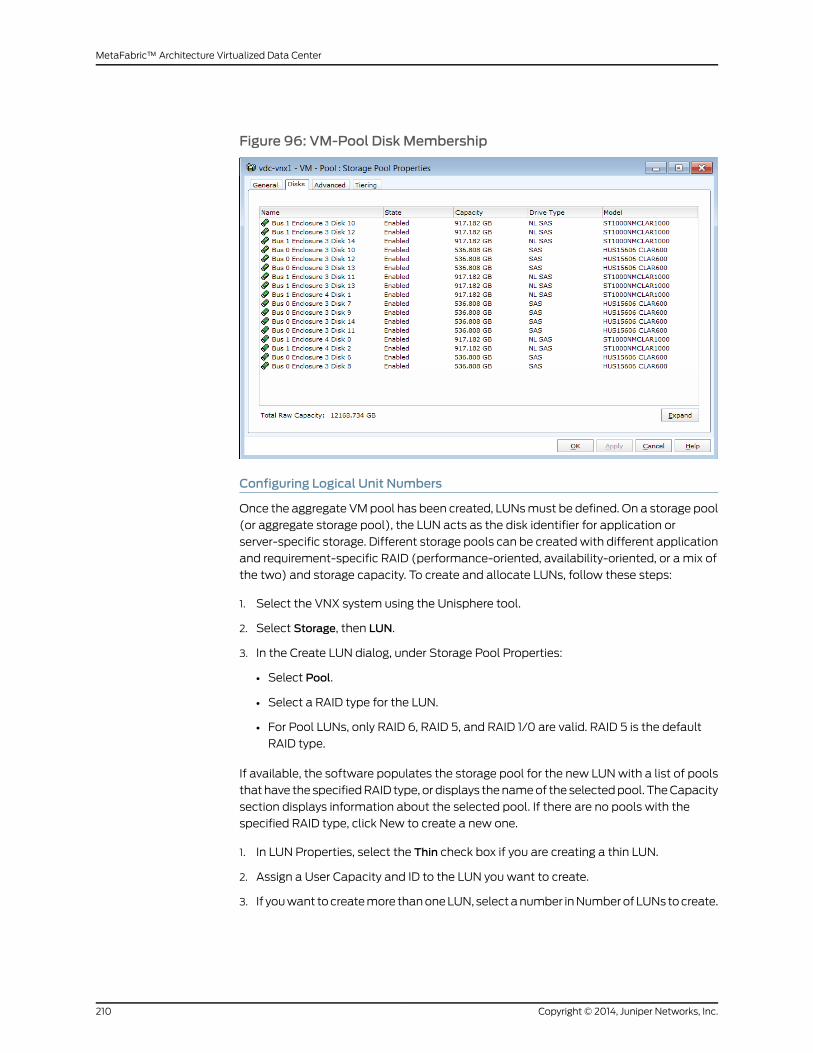
Figure 96: VM-Pool Disk Membership
Configuring Logical Unit Numbers
Once the aggregate VMpool has been created, LUNsmust be defined. On a storage pool
(or aggregate storage pool), the LUN acts as the disk identifier for application or
server-specific storage. Different storage pools can be createdwith different application
and requirement-specific RAID (performance-oriented, availability-oriented, or a mix of
the two) and storage capacity. To create and allocate LUNs, follow these steps:
1. Select the VNX system using the Unisphere tool.
2. Select Storage, then LUN.
3. In the Create LUN dialog, under Storage Pool Properties:
• Select Pool.
• Select a RAID type for the LUN.
• For Pool LUNs, only RAID 6, RAID 5, and RAID 1/0 are valid. RAID 5 is the default
RAID type.
If available, the software populates the storage pool for the new LUNwith a list of pools
that have the specifiedRAID type, or displays thenameof the selectedpool. TheCapacity
section displays information about the selected pool. If there are no pools with the
specified RAID type, click New to create a new one.
1. In LUN Properties, select the Thin check box if you are creating a thin LUN.
2. Assign a User Capacity and ID to the LUN you want to create.
3. If youwant tocreatemore thanoneLUN, selectanumber inNumberofLUNs tocreate.
Copyright © 2014, Juniper Networks, Inc.210
MetaFabric™ Architecture Virtualized Data Center
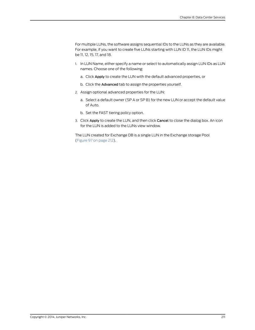
Formultiple LUNs, the software assigns sequential IDs to the LUNs as they are available.
For example, if you want to create five LUNs starting with LUN ID 11, the LUN IDs might
be 11, 12, 15, 17, and 18.
1. In LUNName, either specify a name or select to automatically assign LUN IDs as LUN
names. Choose one of the following:
a. Click Apply to create the LUNwith the default advanced properties, or
b. Click the Advanced tab to assign the properties yourself.
2. Assign optional advanced properties for the LUN:
a. Select a default owner (SP A or SP B) for the new LUN or accept the default value
of Auto.
b. Set the FAST tiering policy option.
3. Click Apply to create the LUN, and then click Cancel to close the dialog box. An icon
for the LUN is added to the LUNs view window.
The LUN created for Exchange DB is a single LUN in the Exchange storage Pool
(Figure 97 on page 212).
211Copyright © 2014, Juniper Networks, Inc.
Chapter 8: Data Center Services

Figure 97: Exchange-DB-LUN Properties
Figure 98 on page 213 shows the LUN assigned to all the ESX hosts. This LUN is created
so that ESX hosts can access this LUN andmount it as a datastore.
Copyright © 2014, Juniper Networks, Inc.212
MetaFabric™ Architecture Virtualized Data Center

Figure 98: LUN Created for All ESX Hosts
A pool was also created for use as a storage destination for Microsoft Exchange logs
(Figure 99 on page 213).
Figure 99: The Selected PoolWas Created for MS Exchange Logs
Once the pool is created, the LUN can be created (Figure 100 on page 214).
213Copyright © 2014, Juniper Networks, Inc.
Chapter 8: Data Center Services
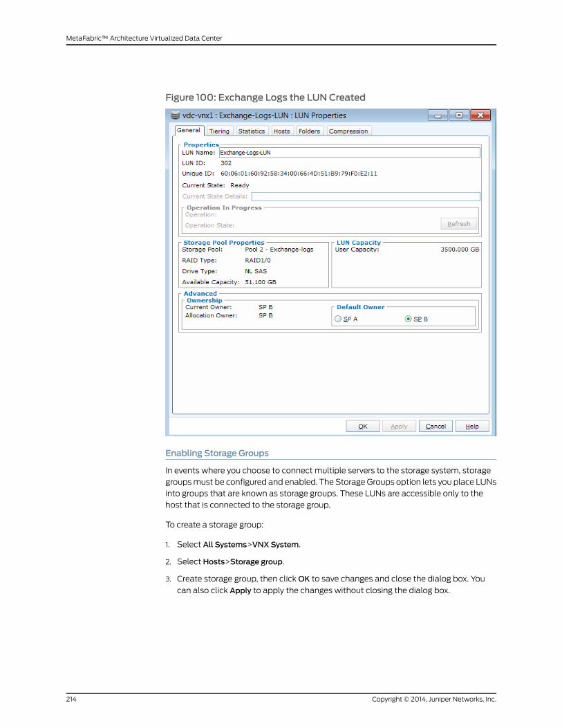
Figure 100: Exchange Logs the LUN Created
Enabling Storage Groups
In events where you choose to connect multiple servers to the storage system, storage
groupsmust be configured and enabled. The Storage Groups option lets you place LUNs
into groups that are known as storage groups. These LUNs are accessible only to the
host that is connected to the storage group.
To create a storage group:
1. Select All Systems>VNX System.
2. Select Hosts>Storage group.
3. Create storage group, then clickOK to save changes and close the dialog box. You
can also click Apply to apply the changes without closing the dialog box.
Copyright © 2014, Juniper Networks, Inc.214
MetaFabric™ Architecture Virtualized Data Center

NOTE: Once you enable Storage Groups for a storage system, any hostcurrently connected to the storage systemwill no longer be able to accessdata on the storage system. To the host, it will appear as if the LUNswereremoved. In order for the host to access the storage data, youmust addLUNs to Storage Group and then connect the host to the Storage Group.
Figure 101 on page 215 shows the properties screen of the ESX-StorageGroup created
in the MetaFabric test lab.
Figure 101: Example Storage Group PropertiesWindow
Once the storage group is created, LUNs can be added to the storage group
(Figure 102 on page 216).
215Copyright © 2014, Juniper Networks, Inc.
Chapter 8: Data Center Services

Figure 102: LUN Added to Storage Group
4. Youmust also add any ESXi hosts to the storage group if those hosts need to access
any data housed on the storage group (Figure 103 on page 217).
Copyright © 2014, Juniper Networks, Inc.216
MetaFabric™ Architecture Virtualized Data Center

Figure 103: ESXi Hosts Added to Storage Group
5. If LUNs are already created, they can be added directly to the storage group by
navigating to the Storage tab, selecting the LUN, and clicking theAdd to storage group
button (Figure 104 on page 217).
Figure 104: Add LUNs to Storage Group
The prior storage sections havemoved you to a point where logical disks now exist
on the storage array. These disks are not formatted and are unusable by the operating
217Copyright © 2014, Juniper Networks, Inc.
Chapter 8: Data Center Services

systems until they have been formatted andmounted. These operations are covered
in the next sections.
Configuring the Network File System
The VNX is a multiprotocol machine that provides access to data through the Network
File System (NFS) protocol. NFS is a client/server distributed file service that provides
file sharing in network environments. The NFS protocol enables the VNX to assume the
functions of an NFS server. NFS environments typically include:
• Native UNIX clients
• Linux clients
• Windows systems configured with third-party applications that provide NFS client
services
When a VNX is configured as an NFS server, file systems are mounted on a Data Mover
and a path to that file system from the Data Mover is exported. Exported file systems
are then available across the network and can bemounted by remote users.
NFS pools are created from the storage pool section of EMC Unisphere. In this example,
we are going to use a storage pool called NFS Pool (Figure 105 on page 218).
Figure 105: NFS Pool Properties
You will recall that a LUNmust be created on top of the storage pool. The LUN is used
as a logical disk identifier that enables the use of the storage (Figure 106 on page 219).
Copyright © 2014, Juniper Networks, Inc.218
MetaFabric™ Architecture Virtualized Data Center

Figure 106: LUN Created on the New Storage Pool
Next, youmust define the NFS pool to enable ESXi hosts to access the storage. To do
this, follow these steps:
1. Select the VNX system in Unisphere.
2. Go to Storage.
3. Select the Storage Configuration.
4. Go to the Storage Pools for file.
5. Create the NFS Pool with storage capacity.
Figure 107onpage220shows theNFSpool properties once thepool hasbeencreated for
server access.
219Copyright © 2014, Juniper Networks, Inc.
Chapter 8: Data Center Services
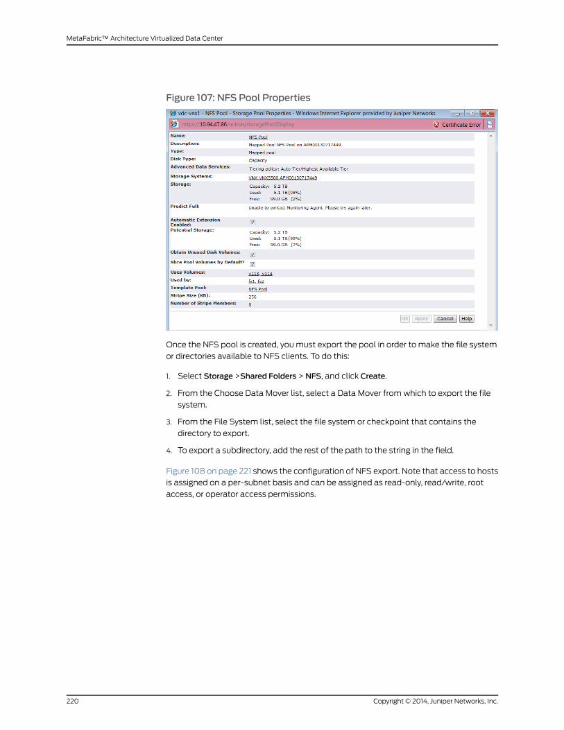
Figure 107: NFS Pool Properties
Once the NFS pool is created, youmust export the pool in order to make the file system
or directories available to NFS clients. To do this:
1. Select Storage >Shared Folders > NFS, and click Create.
2. From the Choose Data Mover list, select a Data Mover fromwhich to export the file
system.
3. From the File System list, select the file system or checkpoint that contains the
directory to export.
4. To export a subdirectory, add the rest of the path to the string in the field.
Figure 108 on page 221 shows the configuration of NFS export. Note that access to hosts
is assigned on a per-subnet basis and can be assigned as read-only, read/write, root
access, or operator access permissions.
Copyright © 2014, Juniper Networks, Inc.220
MetaFabric™ Architecture Virtualized Data Center

Figure 108: NFS Export Configuration
Once you export NFS, the directories contained in the NFSwill be available for mounting
on the application servers.
Configuring VNX Snapshot Replicas
VNX Snapshots is a software feature that creates point in-time data copies. VNX
Snapshots are used for data backups, software development and testing, re-purposing,
data validation, and local rapid restores. VNXSnapshots do not consume large amounts
of pool capacity. As a result, this feature is recommended for use as front-line data
management and recovery.
To configure the snapshot replicas for LUN:
1. Select the VNX system in EMC Unisphere.
2. Go to Dataprotection > Snapshots.
3. Select theSnapshotConfigurationWizard fromthe right side (Figure 109onpage221).
Figure 109: Snapshot ConfigurationWizard
4. Click Next, then select the server host where the LUN is configured andmounted
(Figure 110 on page 222).
221Copyright © 2014, Juniper Networks, Inc.
Chapter 8: Data Center Services

Figure 110: Select Source Server
5. Click Next, then select the target VNX storage system (Figure 111 on page 222), then
click Next.
Figure 111: Select Snapshot Target
Copyright © 2014, Juniper Networks, Inc.222
MetaFabric™ Architecture Virtualized Data Center

6. Select the source LUN (the LUN you wish to snapshot). In this example,
SharePoint-SQL-DB is used as the source LUN and added to the list
(Figure 112 on page 223). Once you have selected the source LUN, click Next.
Figure 112: Select Source LUNs
7. Finally, you can select the default settings or uncheck the Accept Snapshot overhead
values check box andmodify the default settings (Figure 113 on page 224). Once you
have the settings you want, click Next.
223Copyright © 2014, Juniper Networks, Inc.
Chapter 8: Data Center Services

Figure 113: Select Snapshot Storage Overhead
8. Choose to create the Snapshot LUN or choose to not create the Snapshot LUN at the
current time. For this example,wecreated theSnapshot LUN(Figure 114onpage225).
Click Next.
Copyright © 2014, Juniper Networks, Inc.224
MetaFabric™ Architecture Virtualized Data Center
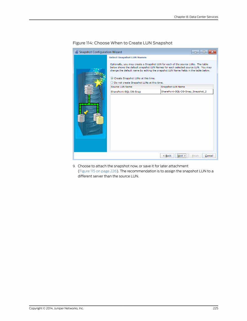
Figure 114: ChooseWhen to Create LUN Snapshot
9. Choose to attach the snapshot now, or save it for later attachment
(Figure 115 on page 226). The recommendation is to assign the snapshot LUN to a
different server than the source LUN.
225Copyright © 2014, Juniper Networks, Inc.
Chapter 8: Data Center Services

Figure 115: Assign Snapshot to a Server
10. Click Finish. Configuration of snapshot LUN is complete (Figure 116 on page 227).
Copyright © 2014, Juniper Networks, Inc.226
MetaFabric™ Architecture Virtualized Data Center
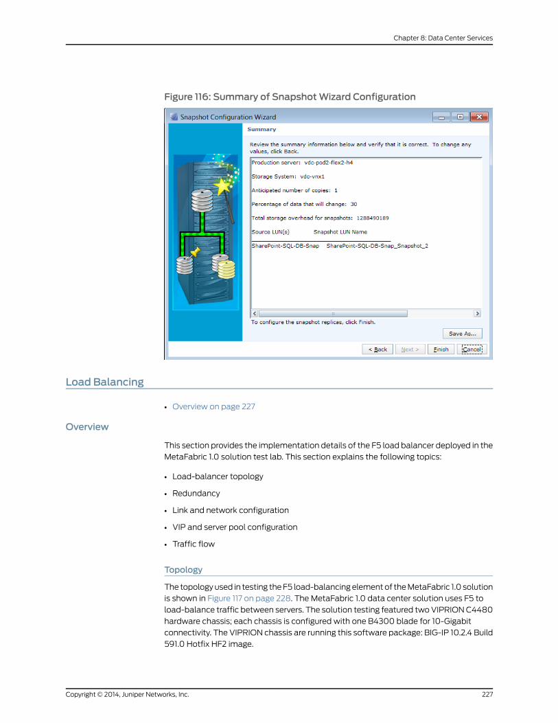
Figure 116: Summary of SnapshotWizard Configuration
Load Balancing
• Overview on page 227
Overview
This section provides the implementation details of the F5 load balancer deployed in the
MetaFabric 1.0 solution test lab. This section explains the following topics:
• Load-balancer topology
• Redundancy
• Link and network configuration
• VIP and server pool configuration
• Traffic flow
Topology
The topologyused in testing theF5 load-balancingelementof theMetaFabric 1.0 solution
is shown in Figure 117 on page 228. The MetaFabric 1.0 data center solution uses F5 to
load-balance traffic between servers. The solution testing featured twoVIPRIONC4480
hardware chassis; each chassis is configured with one B4300 blade for 10-Gigabit
connectivity. The VIPRION chassis are running this software package: BIG-IP 10.2.4 Build
591.0 Hotfix HF2 image.
227Copyright © 2014, Juniper Networks, Inc.
Chapter 8: Data Center Services

Figure 117: Load Balancing Topology
In this solution, twoVIPRION systems are connected to the core switches using LAG. The
F5 systems are configured with virtual IPs (VIPs) and server pools to provide
load-balancing services to SharePoint, Wikimedia, and Exchange traffic. SharePoint,
Wiki, and Exchange servers are connected to POD switches on VLAN 102,103, and 104,
respectively. DSRmode is configured in F5 to bypass return traffic from server for all the
VIPs.
Configuring Redundancy
Each VIPRION system is configured as a cluster in this topology, although they can also
be configured as single devices. In this solution, the twoVIPRION systems are configured
as two clusters (one cluster per chassis), deployed in active/standbymode for
redundancy. This means that one cluster is active and processing network traffic, while
the other cluster is up and available to process traffic, but is in a standby state. If the
active cluster becomes unavailable, the standby cluster automatically becomes active,
and begins processing network traffic.
For redundancy, a dedicated failover link is configured between two VIPRION systems
as a LAG interface. Interfaces 1/1.3 and 1/1.4 in LAG are configured as failover links on
both systems. The following steps are required to configure redundancy (failover):
1. Create an interface trunk dedicated for failover.
2. Create a dedicated failover VLAN.
3. Create a self IP address and associate the self IP with the failover VLAN.
Copyright © 2014, Juniper Networks, Inc.228
MetaFabric™ Architecture Virtualized Data Center

4. Define a unicast entry specifying the local and remote self IP addresses.
5. Define amulticast entry using the management interface for each VIPRION system.
For more information on redundancy and failover configuration of the F5 Load Balancer,
see:
http://support.f5.com/kb/en-us/solutions/public/11000/900/sol11939.html
For more information on redundant cluster configuration, see:
http://support.f5.com/kb/en-us/products/big-ip_ltm/manuals/product/VIPRION_configuration_guide_961/clustered_systems_redundant.html
Configuring the Link and Network
The F5 load-balancing topology deployed in this solution features two LAG interfaces.
OneLAG isconfigured forexternal connectivity (receivesservice request toVIPsconfigured
on F5 from the Internet) andone LAG is configured for internal connectivity to the servers
connected to the PODs. Both the F5 systems are configured with external and internal
connectivity and those interfaces on both systemswill be in theUP state. Only the active
F5systemprocesses traffic - the standbyonlyprocesses traffic in caseswhere theprimary
experiences a failure.
Each LAG in F5 systemhas twomember links. Onemember link connects to Core Switch
1 and the other connects to Core Switch 2. MC-LAG is configured on the core switches.
To the F5, it appears that the LAG is connecting to a single system. LACP is used as
control protocol for creating LAG between F5 and core switches.
The following configurations are performed on both F5 systems to enable external
connectivity:
• Create a LAG named External on both F5 systems, and assign interfaces 1/1.5 and 1/1.6
as members of that LAG.
• Create VLAN 15 and name it External on both F5 systems and the VLAN assigned to
the External LAG.
• Configure a self IP address of 192.168.15.3 on the active F5 system, and 192.168.15.4 on
the standby F5 system for VLAN 15.
• Create a floating IP address 192.168.15.5 on the active F5 system. This floating IP
address is active on the active F5 cluster. If the active load balancer fails, this floating
IP address is used on new active load balancer
Configure internal connectivity with the following steps:
• Create a LAG named core-sw on both F5 systems, and assign interfaces 1/1.1 and 1/1.2
as members of that LAG.
• VLANs 102, 103, and 104 are named Core-Access, Wikimedia-Access, and
Exchange-Access, respectively. These VLANs were created on both the F5 systems
and the VLANs, and are assigned to the core-sw LAG. As per their Access names, the
SharePoint, Wikimedia, and Exchange servers are located in VLANs 102, 103, and 104,
respectively.
229Copyright © 2014, Juniper Networks, Inc.
Chapter 8: Data Center Services

• Create a self IP address of 172.16.2.25, 172.16.3.25, and 172.16.4.25 for VLANs 102, 103,
and 104
Internal connections to the servers are configured as a Layer 2 connection through the
POD switches (that are connected to the core switches).
NOTE: For external connections, static routes are advertised from the coreswitch for VIPs configured in F5 for clients in the Internet to send requests tothe VIP for specific services like Exchange, Wikimedia, and SharePoint. Forthe static route, we configured a floating IP address created for “external”VLAN 192.168.15.5 as the next hop to reach the VIPs.When the active clusterfails, thenewactiveuses theconfigured floating IPaddress, sendsagratuitousARP for this floating IP address, and begins receiving traffic.
Configuring VIP and Server Pool
A virtual server IP address (VIP) is a traffic-management object on the F5 system that
is represented by an IP address and a service. Clients on an external network can send
application traffic to a virtual server, which then directs the traffic according to the VIP
configuration. Themain purpose of a virtual server is to balance traffic load across a pool
of servers on an internal network. Virtual servers increase the availability of resources for
processing client requests by monitoring server load and distributing the load across all
available servers for a particular service.
NOTE: In this solution testing, nPath routing (DSR, or Direct Server Return)is used to bypass the F5 for return path traffic from servers, routing trafficdirectly to the destination from the application servers.
It is recommended to use the nPath template in the F5 configuration GUI (Template and
wizards window) to configure VIP and server pools in DSRmode. The following link
provides greater detail regarding configuration of nPath in F5 systems:
http://support.f5.com/kb/en-us/products/big-ip_ltm/manuals/product/ltm_implementations_guide_10_1/sol_npath.html
In this solution, configure three VIP addresses 10.94.127.180, .181, and .182, and assign
server pools to these VIPs using the nPath template to service SharePoint, Exchange,
andWikimedia services.
The following tasks need to be completed in order to configure the BIG-IP system to use
nPath routing:
• Create a custom Fast L4 profile.
• Create a pool that contains the content servers.
• Defineavirtual serverwithport andaddress translationdisabledandassign thecustom
Fast L4 profile to it.
• Configure the virtual server address on each server loopback interface.
Copyright © 2014, Juniper Networks, Inc.230
MetaFabric™ Architecture Virtualized Data Center
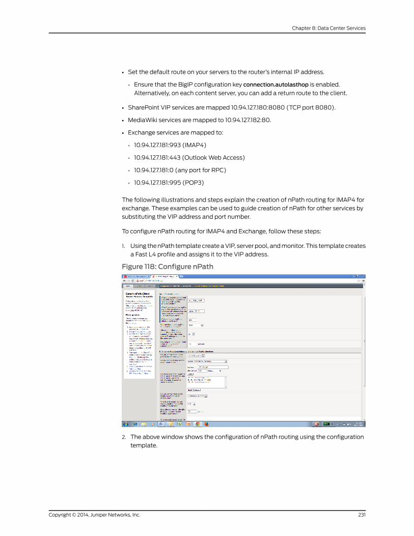
• Set the default route on your servers to the router’s internal IP address.
• Ensure that the BigIP configuration key connection.autolasthop is enabled.
Alternatively, on each content server, you can add a return route to the client.
• SharePoint VIP services are mapped 10.94.127.180:8080 (TCP port 8080).
• MediaWiki services are mapped to 10.94.127.182:80.
• Exchange services are mapped to:
• 10.94.127.181:993 (IMAP4)
• 10.94.127.181:443 (OutlookWeb Access)
• 10.94.127.181:0 (any port for RPC)
• 10.94.127.181:995 (POP3)
The following illustrations and steps explain the creation of nPath routing for IMAP4 for
exchange. These examples can be used to guide creation of nPath for other services by
substituting the VIP address and port number.
To configure nPath routing for IMAP4 and Exchange, follow these steps:
1. Using thenPath template createaVIP, server pool, andmonitor. This template creates
a Fast L4 profile and assigns it to the VIP address.
Figure 118: Configure nPath
2. The above window shows the configuration of nPath routing using the configuration
template.
231Copyright © 2014, Juniper Networks, Inc.
Chapter 8: Data Center Services

a. Assign a unique prefix name (my_nPath_IMAP) for the F5 system to name the
server pool, monitor, and other objects.
b. To create the IMAP4 VIP as part of the Exchange service, specify the VIP address
10.94.127.181, TCP port 993.
c. This template gives a choice for creating a new server pool or using an existing
pool. By default, it creates a new server pool using the prefix name shown
(my_nPath_IMAP_pool). Add servers one at a time with the IP address and port
number, as shown.
d. This templategivesachoice for creatinganewmonitor or usinganexistingmonitor.
By default, it creates a newmonitor using the prefix name shown
(my_nPath_IMAP_TCP_pool). By default, it uses TCPmonitoring and the user can
change themonitoring type.Thedefault interval for thehealthcheck is 30seconds,
and the timeout value is 91 seconds.
e. ClickFinished to createnPath routing for an IMAPservicewithVIP 10.94.127.181:993.
NOTE: The default TCPmonitor, with no Send string or Receive stringconfigured, tests a service by establishing aTCP connectionwith the poolmember on the configured service port and then immediately closes theconnectionwithoutsendinganydataon theconnection.Thiscausessomeservices such as telnet and ssh to log a connection error, and fills up theserver logs with unnecessary errors. To eliminate the extraneous logging,youcanconfigure theTCPmonitor to send just enoughdata to theservice,or just use the tcp_half_openmonitor. Depending on your monitoringrequirements, youmight also be able tomonitor a service that expectsempty connections, such as tcp_echo (by using the default tcp_echomonitor). NOTE: Each server has four 10-Gb NIC ports connected to theQFX3000-MQFabric PODs as a data port for all VM traffic. Each systemisconnected toeachPODfor redundancypurposes.The IBMSystem3750is connected to POD1 using 4 x 10-Gigabit Ethernet. A second IBMSystem3750 connects to POD2 using 4 x 10-Gigabit Ethernet. The use of a LAGprovides switching redundancy in case of a POD failure.
3. Create or verify other objects (Pool, Profile, or Monitor) using the template created
with the VIP. As you can see, nPath routing created Fast L4 Profile as needed.
Copyright © 2014, Juniper Networks, Inc.232
MetaFabric™ Architecture Virtualized Data Center
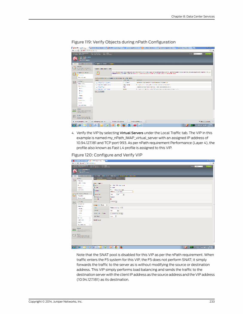
Figure 119: Verify Objects during nPath Configuration
4. Verify the VIP by selecting Virtual Servers under the Local Traffic tab. The VIP in this
example is namedmy_nPath_IMAP_virtual_server with an assigned IP address of
10.94.127.181 and TCP port 993. As per nPath requirement Performance (Layer 4), the
profile also known as Fast L4 profile is assigned to this VIP.
Figure 120: Configure and Verify VIP
Note that the SNAT pool is disabled for this VIP as per the nPath requirement. When
traffic enters the F5 system for this VIP, the F5 does not perform SNAT; it simply
forwards the traffic to the server as is without modifying the source or destination
address. This VIP simply performs load balancing and sends the traffic to the
destination serverwith theclient IPaddressas the sourceaddressand theVIPaddress
(10.94.127.181) as its destination.
233Copyright © 2014, Juniper Networks, Inc.
Chapter 8: Data Center Services
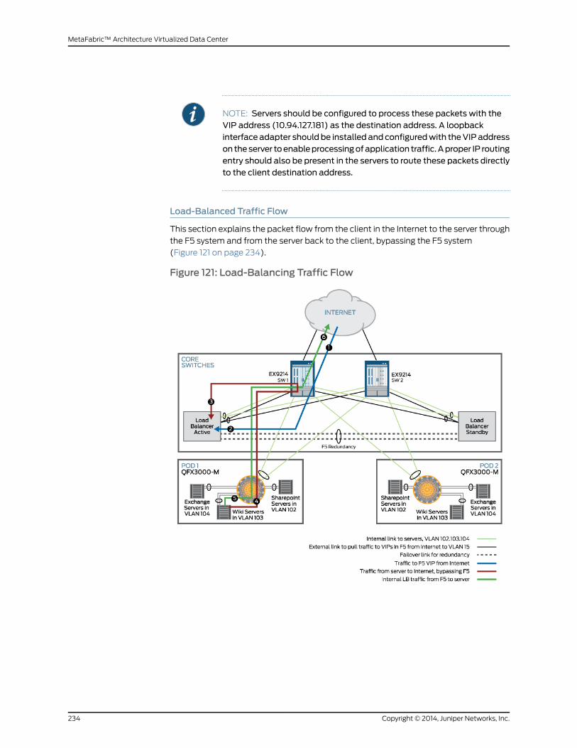
NOTE: Servers should be configured to process these packets with theVIP address (10.94.127.181) as the destination address. A loopbackinterfaceadapter shouldbe installed andconfiguredwith theVIPaddresson theserver toenableprocessingofapplication traffic.Aproper IP routingentry should also be present in the servers to route these packets directlyto the client destination address.
Load-Balanced Traffic Flow
This section explains the packet flow from the client in the Internet to the server through
the F5 system and from the server back to the client, bypassing the F5 system
(Figure 121 on page 234).
Figure 121: Load-Balancing Traffic Flow
Copyright © 2014, Juniper Networks, Inc.234
MetaFabric™ Architecture Virtualized Data Center
The flow of traffic to and from the load balancers flows in the following manner:
1. As described in Figure 121 on page 234, three VIPs are created in the F5 system for
SharePoint, Wikimedia, and Exchange. Assume that the client sends the request to
theWikimedia server. In this case, the client sends the request to the VIP address of
10.94.127.182 and the source IP address is the client’s IP address. The destination IP
address will be the VIP IP address (10.94.127.182) and the destination port will be 80.
As described in the previous section, the core switch advertises the VIP address in the
network. As a result, the edge router knows the route to reach the VIP address of
10.94.127.182.
2. This packet arrives on the active F5 via external LAG. Because of the nPath
configuration, theWikimedia VIP address load-balances the traffic and sends it to
one of the servers without modifying the source or destination address.
3. Because of the nPath configuration, theWikimedia VIP address load-balances the
traffic and sends it to one of the servers as is without modifying the source or the
destination address. The F5 system reaches theWikimedia servers by way of a Layer
2 connection on VLAN 103. An internal LAG connection is a trunk port carrying VLANs
102, 103, and 104 to reach all the servers.
4. TheWikimedia server receives the traffic on the loopback address (configured with
VIP IP 10.94.127.182) and processes it.
5. TheWikimedia server sends this packet back to the client by way of a router and
bypassing the F5 system.
6. The return packet reaches the client.
Applications
• Overview on page 235
• Microsoft Exchange Implementation on page 235
Overview
The Juniper MetaFabric 1.0 solution featured several business-critical applications in the
test and verification lab. This section will cover implementation details for the following
applications:
• Microsoft Exchange
Microsoft Exchange Implementation
This section describes the design, planning, and instructions for deploying a highly
available Microsoft Exchange Server 2012 cluster for client access service andmailbox
database server using VMware high availability (HA). It covers configuration guidelines
for the VMware vSphere HA cluster parameters for the cluster and best practice
recommendation. This guide does not cover a full installation of Microsoft Exchange
Server. This section covers the following topics:
• Installation checklist and scope
235Copyright © 2014, Juniper Networks, Inc.
Chapter 8: Data Center Services
• Network for Exchange VM
• Storage for Exchange VM
Installation Checklist and Scope
This section contains detailed instructions on configuring network and storage. We
assume that the following elements are already installed:
• ESXi 5.1 hypervisor on the IBM Flex chassis compute node.
• vCenter Server to manage ESXi 5.1 hosts.
This deployment example assumes that VMware HA is configured on ESXi hosts using
vCenter Server. Virtualmachines that are runningonanESXi host at the timeof complete
failure will be automatically migrated.
VMware vSphere HA requirements:
• All hosts inavSphereHA-enabledclustermusthaveaccess to the samesharedstorage
location used by the VM on the cluster. This includes any Fibre channel, FCoE, iSCSI,
and NFS datastores used by the VM. In this solution, we are using iSCSI and NFS
datastores.
• All hosts in a vSphere HA cluster should have an identical virtual networking
configuration. In this solution, all hosts are participating the same vSphere Distributed
Switch (vDS).
Deploying Network for Exchange VM
Microsoft Exchange is a two-tier application that includes a Client Access Server (CAS)
andmailbox database server. Exchange was deployed in POD1 during testing. CAS is a
front-end server for user mailboxes; the mailbox database is the back-end server. The
entire user’s mailbox is accessed from themailbox database server. The cluster is
configured on back-end servers called the Exchange database availability group (DAG).
10,000usersarecreatedonanLDAPserver (Windowsdomaincontroller),ActiveDirectory
using the DATACENTER domain. All of the tested Microsoft Enterprise applications
(including Microsoft Exchange) were integrated with theWindows domain controller
(DATACENTER). In this solution, all applications are using separate VLANs to ensure
traffic isolation.
Deployment of Microsoft Exchange requires the following steps:
• Define the network prefix.
• Define VLANs.
Copyright © 2014, Juniper Networks, Inc.236
MetaFabric™ Architecture Virtualized Data Center

NOTE: TheWindows domain controller (DATACENTER) is considered aninfrastructure prefix and is assigned to a separate network. This design andimplementation assumes that this VLAN (and prefix/gateway) has alreadybeen defined on the switches.
TheWindows domain controller subnet is 172.16.1.0/24, and the defaultgateway is 172.16.1.254.
TwoWindows domain controllers were installed and configured, one is inPOD1 and other is in POD2 for redundancy. The assigned IP addresses forboth domain controllers are 172.16.1.11 and 172.16.1.10, respectively.
1. Define network subnets for assignment to Exchange server elements.
a. ExchangeServer is 172.16.4.0/24, the default gateway is 172.16.4.254. The exchange
server is scaled to serve 10,000 users, and 3 client access servers (CAS) have been
installed and configured. Server IP addresses are 172.16.4.10, 172.16.4.11, 172.16.4.12,
and 172.16.4.13.
b. Exchange DAG Cluster is 172.16.9.0/24 and the default gateway is 172.16.9.254.
Thecluster is configured tohost threemailboxdatabase servers. Theusers primary
mailbox database is active on one server with the backupmailbox databases
available on the other two servers. Themailbox database servers communicate
over VLAN-109 (The VLAN over which the DAG Cluster is configured).
2. Define VLANs for Exchange elements (enables traffic isolation).
a. Exchange server = VLAN and vlan-id 104.
b. Exchange Mailbox cluster = VLAN and vlan-id 109.
3. Configure theVLANandgatewayaddressonQFabric switch (POD1)as thisapplication
is located only in POD1.
[edit]set vlans Exchange vlan-id 104set vlans Exchange l3-interface vlan.104set interfaces vlan unit 104 family inet address 172.16.4.254/24set protocols ospf area 0.0.0.10 interface vlan.104 passiveset vlans Exchange-Cluster vlan-id 109
4. Configure VLANs on all IBM Pure Flex system CNAmodules.
vlan 104enablename "EXCHANGE"member INTA1-INTA5,INTB1-INTB5,EXT1-EXT3,EXT7
vlan 109enablename "Exchange DAG"member INTA1-INTA5,INTB1-INTB5,EXT1-EXT3,EXT7
Below configuration shows of 10Gb CNA I/OModule 1 and 2.
237Copyright © 2014, Juniper Networks, Inc.
Chapter 8: Data Center Services
vlan 104enablename "Exchange"member INTA1-INTA5,EXT1-EXT2,EXT11-EXT16
vlan 109enablename "Exchange DAG"member INTA1-INTA5,EXT1-EXT2,EXT11-EXT16
NOTE: This configuration is not required if you are using IBM Flex SystemPass-thrumodules. This configuration is an example of the 40-Gb CNAI/OModule (module 1 and 2).
5. Configure VLANs on LAVC switches.
[edit]set interfaces ae1 unit 0 family ethernet-switching vlanmembers Exchangeset interfaces ae2 description "IBM Standalone server"set interfaces ae2 unit 0 family ethernet-switching vlanmembers Exchangeset interfaces ae2 unit 0 family ethernet-switching vlanmembers Exchange-clusterset interfaces ae3 description IBM-FLEX-10-CNA-VLAG-BNTset interfaces ae3 unit 0 family ethernet-switching vlanmembers Exchange-clusterset interfaces ae3 unit 0 family ethernet-switching vlanmembers Exchangeset interfaces ae4 description IBM-FLEX-2-CN-1-Passthroughset interfaces ae4 unit 0 family ethernet-switching vlanmembers Exchange-clusterset interfaces ae4 unit 0 family ethernet-switching vlanmembers Exchangeset interfaces ae5 description IBM-FLEX-2-CN-2set interfaces ae5 unit 0 family ethernet-switching vlanmembers Exchange-clusterset interfaces ae5 unit 0 family ethernet-switching vlanmembers Exchangeset interfaces ae6 description IBM-FLEX-2-CN-3set interfaces ae6 unit 0 family ethernet-switching vlanmembers Exchange-clusterset interfaces ae6 unit 0 family ethernet-switching vlanmembers Exchangeset interfaces ae7 description IBM-FLEX-2-CN-4set interfaces ae7 unit 0 family ethernet-switching vlanmembers Exchange-clusterset interfaces ae7 unit 0 family ethernet-switching vlanmembers Exchangeset interfaces ae8 description IBM-FLEX-2-CN5set interfaces ae8 unit 0 family ethernet-switching vlanmembers Exchangeset interfaces ae8 unit 0 family ethernet-switching vlanmembers Exchange-clusterset vlans Exchange vlan-id 104set vlans Exchange-cluster vlan-id 109
6. Allow same VLANs and configure Layer 3 gateway for Exchange-Cluster on both core
switches Core1 and Core2.
[edit]set interfaces ae1 description "MC-LAG to vdc-pod1-sw1-nng-ae1"set interfaces ae1 unit 0 family ethernet-switching vlanmembers Exchangeset interfaces ae2 description "MC-LAG to vdc-pod1-sw1-nng-ae2"set interfaces ae2 unit 0 family ethernet-switching vlanmembers Exchange-Clusterset interfaces ae4 description "MC-LAG to vdc-pod2-sw1-ae0"set interfaces ae4 unit 0 family ethernet-switching vlanmembers Exchange-Clusterset interfaces ae5 description "MC-LAG to vdc-pod2-sw1-ae1"set interfaces ae5 unit 0 family ethernet-switching vlanmembers Exchange
Copyright © 2014, Juniper Networks, Inc.238
MetaFabric™ Architecture Virtualized Data Center
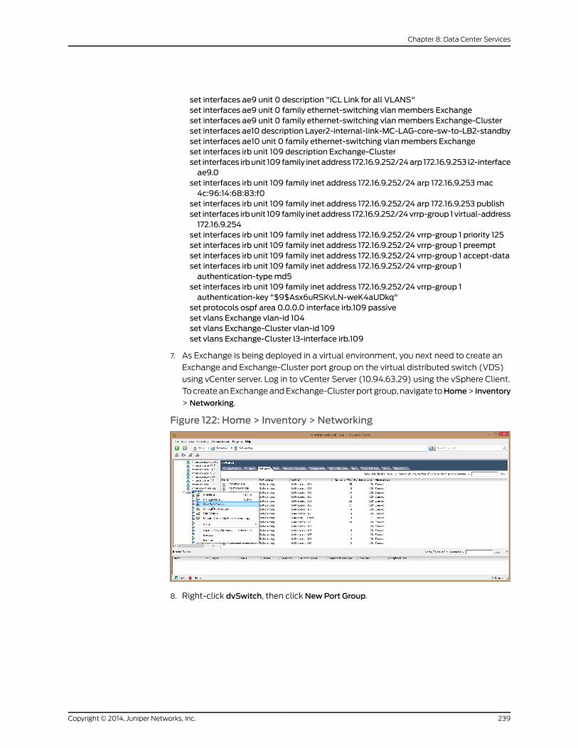
set interfaces ae9 unit 0 description "ICL Link for all VLANS"set interfaces ae9 unit 0 family ethernet-switching vlanmembers Exchangeset interfaces ae9 unit 0 family ethernet-switching vlanmembers Exchange-Clusterset interfaces ae10 description Layer2-internal-link-MC-LAG-core-sw-to-LB2-standbyset interfaces ae10 unit 0 family ethernet-switching vlanmembers Exchangeset interfaces irb unit 109 description Exchange-Clusterset interfaces irbunit 109 family inetaddress 172.16.9.252/24arp 172.16.9.253 l2-interfaceae9.0
set interfaces irb unit 109 family inet address 172.16.9.252/24 arp 172.16.9.253mac4c:96:14:68:83:f0
set interfaces irb unit 109 family inet address 172.16.9.252/24 arp 172.16.9.253 publishset interfaces irbunit 109 family inetaddress 172.16.9.252/24vrrp-group 1virtual-address172.16.9.254
set interfaces irb unit 109 family inet address 172.16.9.252/24 vrrp-group 1 priority 125set interfaces irb unit 109 family inet address 172.16.9.252/24 vrrp-group 1 preemptset interfaces irb unit 109 family inet address 172.16.9.252/24 vrrp-group 1 accept-dataset interfaces irb unit 109 family inet address 172.16.9.252/24 vrrp-group 1authentication-typemd5
set interfaces irb unit 109 family inet address 172.16.9.252/24 vrrp-group 1authentication-key "$9$Asx6uRSKvLN-weK4aUDkq"
set protocols ospf area 0.0.0.0 interface irb.109 passiveset vlans Exchange vlan-id 104set vlans Exchange-Cluster vlan-id 109set vlans Exchange-Cluster l3-interface irb.109
7. As Exchange is being deployed in a virtual environment, you next need to create an
Exchange and Exchange-Cluster port group on the virtual distributed switch (VDS)
using vCenter server. Log in to vCenter Server (10.94.63.29) using the vSphere Client.
TocreateanExchangeandExchange-Cluster port group, navigate toHome> Inventory
> Networking.
Figure 122: Home > Inventory > Networking
8. Right-click dvSwitch, then click NewPort Group.
239Copyright © 2014, Juniper Networks, Inc.
Chapter 8: Data Center Services

Figure 123: Create NewPort Group
9. ClickNext, then Finish. Once the Exchange port group is created, you can edit the port
group by right--clicking and thenmodifying the teaming policy.
Copyright © 2014, Juniper Networks, Inc.240
MetaFabric™ Architecture Virtualized Data Center
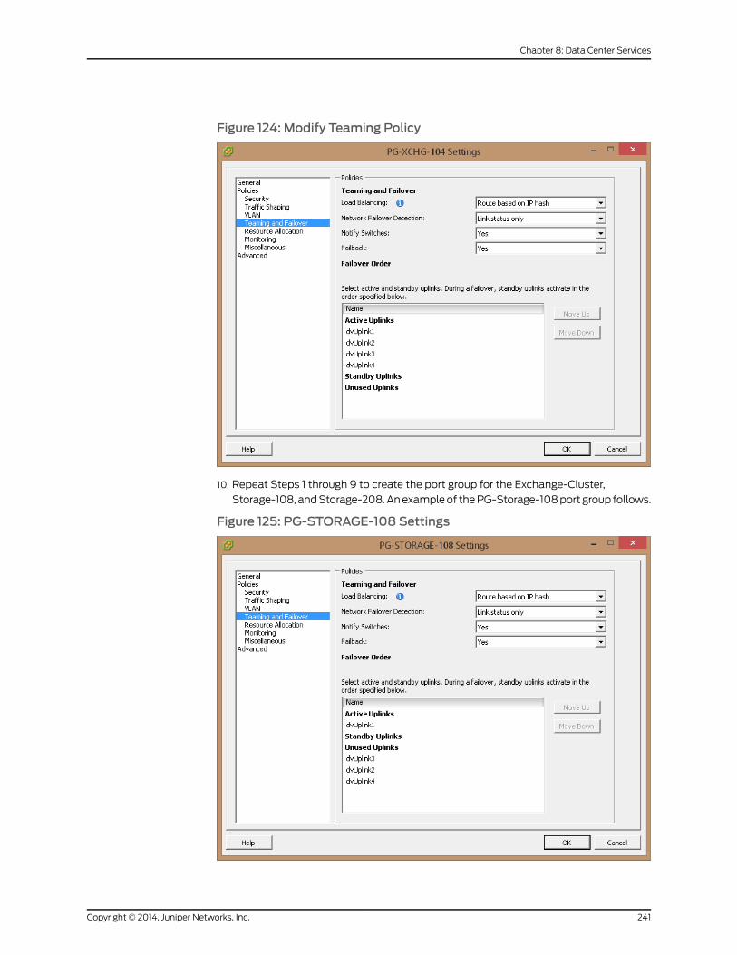
Figure 124: Modify Teaming Policy
10. Repeat Steps 1 through 9 to create the port group for the Exchange-Cluster,
Storage-108, andStorage-208.Anexampleof thePG-Storage-108port group follows.
Figure 125: PG-STORAGE-108 Settings
241Copyright © 2014, Juniper Networks, Inc.
Chapter 8: Data Center Services
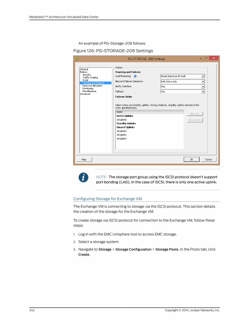
An example of PG-Storage-208 follows.
Figure 126: PG-STORAGE-208 Settings
NOTE: The storage port group using the iSCSI protocol doesn’t supportport bonding (LAG). In the case of iSCSI, there is only one active uplink.
Configuring Storage for Exchange VM
The Exchange VM is connecting to storage via the iSCSI protocol. This section details
the creation of the storage for the Exchange VM.
To create storage via iSCSI protocol for connection to the Exchange VM, follow these
steps:
1. Log in with the EMC Unisphere tool to access EMC storage.
2. Select a storage system.
3. Navigate to Storage > Storage Configuration > Storage Pools. In the Pools tab, click
Create.
Copyright © 2014, Juniper Networks, Inc.242
MetaFabric™ Architecture Virtualized Data Center

Figure 127: EMCUnisphere Tool
4. Provide a name for the storage pool (in this example, Pool 1 – Exchange-DB).
Figure 128: Create Storage Pool Name
5. Ensure that FAST Cache is enabled (under the Advanced tab).
243Copyright © 2014, Juniper Networks, Inc.
Chapter 8: Data Center Services
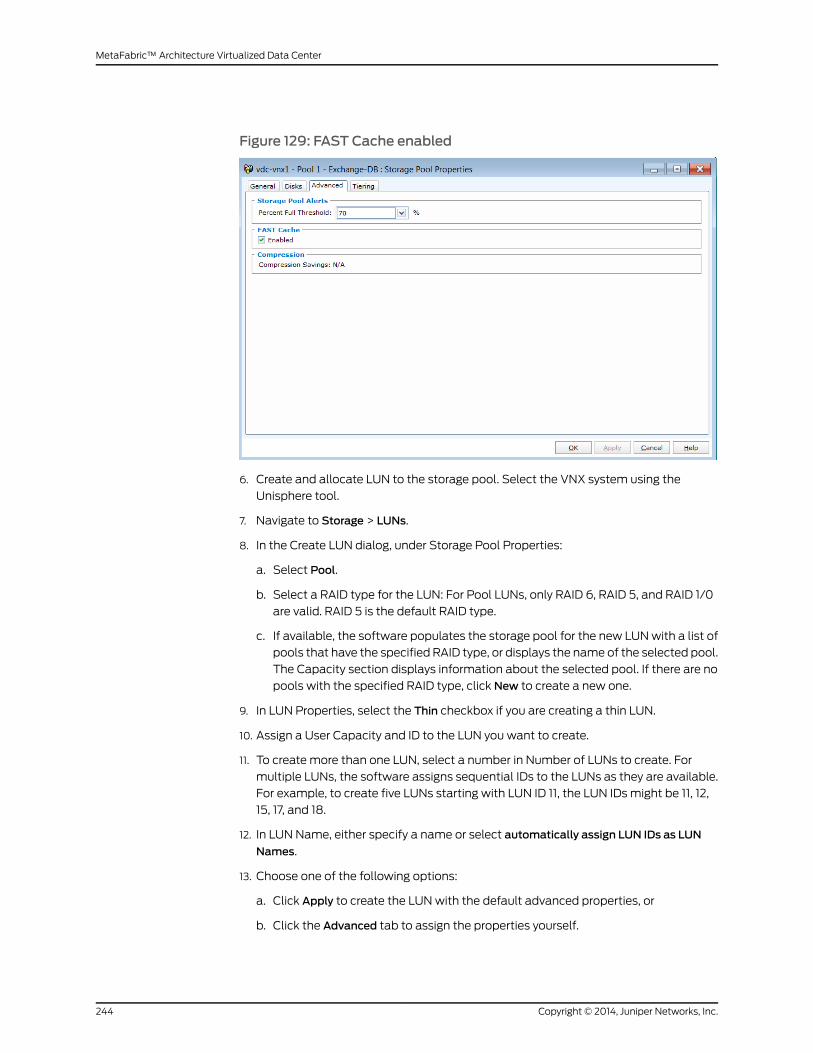
Figure 129: FAST Cache enabled
6. Create and allocate LUN to the storage pool. Select the VNX system using the
Unisphere tool.
7. Navigate to Storage > LUNs.
8. In the Create LUN dialog, under Storage Pool Properties:
a. Select Pool.
b. Select a RAID type for the LUN: For Pool LUNs, only RAID 6, RAID 5, and RAID 1/0
are valid. RAID 5 is the default RAID type.
c. If available, the software populates the storage pool for the new LUNwith a list of
pools that have the specified RAID type, or displays the name of the selected pool.
The Capacity section displays information about the selected pool. If there are no
pools with the specified RAID type, click New to create a new one.
9. In LUN Properties, select the Thin checkbox if you are creating a thin LUN.
10. Assign a User Capacity and ID to the LUN you want to create.
11. To create more than one LUN, select a number in Number of LUNs to create. For
multiple LUNs, the software assigns sequential IDs to the LUNs as they are available.
For example, to create five LUNs starting with LUN ID 11, the LUN IDs might be 11, 12,
15, 17, and 18.
12. In LUN Name, either specify a name or select automatically assign LUN IDs as LUN
Names.
13. Choose one of the following options:
a. Click Apply to create the LUNwith the default advanced properties, or
b. Click the Advanced tab to assign the properties yourself.
Copyright © 2014, Juniper Networks, Inc.244
MetaFabric™ Architecture Virtualized Data Center

14. Assign optional advanced properties for the LUN:
a. Select a default owner (SP A or SP B) for the new LUN or accept the default value
of Auto.
b. Set the FAST tiering policy option.
15. Click Apply to create the LUN, and then click Cancel to close the dialog box. An icon
for the LUN is added to the LUN viewwindow. Below is an example of the Exchange
LUN that was created.
Figure 130: Exchange-DB LUN
Enabling Storage Groups with Unisphere
Youmust enable storage groups using Unisphere if only one server is connected to the
system and you want to connect additional servers to the system. The Storage Groups
option lets you place LUNs into groups that are known as storage groups. These LUNs
are accessible only to the host that is connected to the storage group. To enable storage
groups with Unisphere:
245Copyright © 2014, Juniper Networks, Inc.
Chapter 8: Data Center Services
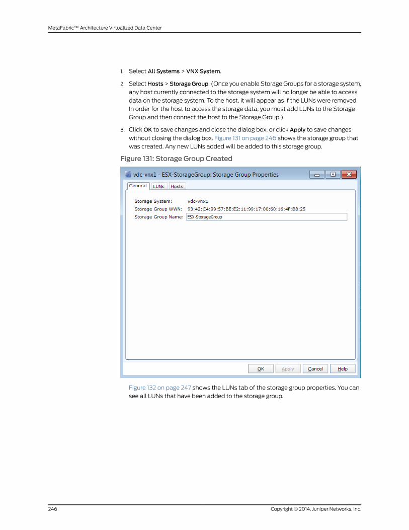
1. Select All Systems > VNX System.
2. SelectHosts>StorageGroup. (Once you enable StorageGroups for a storage system,
any host currently connected to the storage systemwill no longer be able to access
data on the storage system. To the host, it will appear as if the LUNs were removed.
In order for the host to access the storage data, youmust add LUNs to the Storage
Group and then connect the host to the Storage Group.)
3. ClickOK to save changes and close the dialog box, or click Apply to save changes
without closing the dialog box. Figure 131 on page 246 shows the storage group that
was created. Any new LUNs added will be added to this storage group.
Figure 131: Storage Group Created
Figure 132 on page 247 shows the LUNs tab of the storage group properties. You can
see all LUNs that have been added to the storage group.
Copyright © 2014, Juniper Networks, Inc.246
MetaFabric™ Architecture Virtualized Data Center

Figure 132: Storage Group Properties - LUNs Tab
4. From the Hosts tab (Storage Group Properties), you can select hosts to add to the
storage pool (which hosts are able to access the pool).
247Copyright © 2014, Juniper Networks, Inc.
Chapter 8: Data Center Services

Figure 133: Hosts Allowed to Access the Storage Group
Once the storage group is created, LUNs can be added directly to the storage pool
from the Storage > LUNs screen.
Figure 134: Add LUN to Storage Group
Provisioning LUNs to ESXi Hosts
TheLUNscreated in theprevious stepsnowneed tobeaddedandmountedasdatastores
on the appropriate ESXi hosts. To do this, youmust first configure the VMware kernel
Copyright © 2014, Juniper Networks, Inc.248
MetaFabric™ Architecture Virtualized Data Center

network. ESXi uses VMkernel ports for systemmanagement and IP storage. VMkernel
IP storage interfaces provide access to one or more EMC VNX iSCSI network portals or
NFS servers.
To configure VMkernel:
1. Log in to the VMware vSphere client to the vCenter Server.
2. Navigate to Home > Inventory > Hosts and Clusters.
3. Select the hosts and on the right side, click Configuration.
4. Under Networking, vSphere Distributed Switch, clickManage Virtual Adapters.
Figure 135: Manage Virtual Adapters
5. Click Add to create a new VMkernel port, then click Next.
249Copyright © 2014, Juniper Networks, Inc.
Chapter 8: Data Center Services
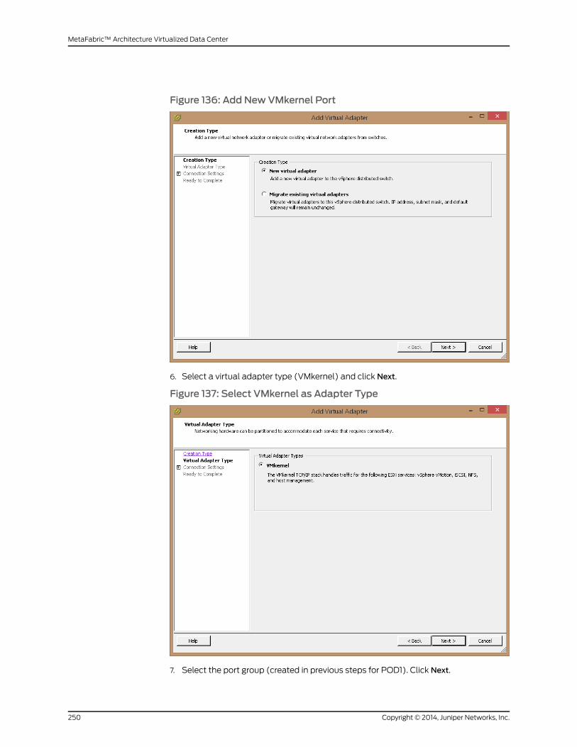
Figure 136: Add NewVMkernel Port
6. Select a virtual adapter type (VMkernel) and click Next.
Figure 137: Select VMkernel as Adapter Type
7. Select the port group (created in previous steps for POD1). Click Next.
Copyright © 2014, Juniper Networks, Inc.250
MetaFabric™ Architecture Virtualized Data Center
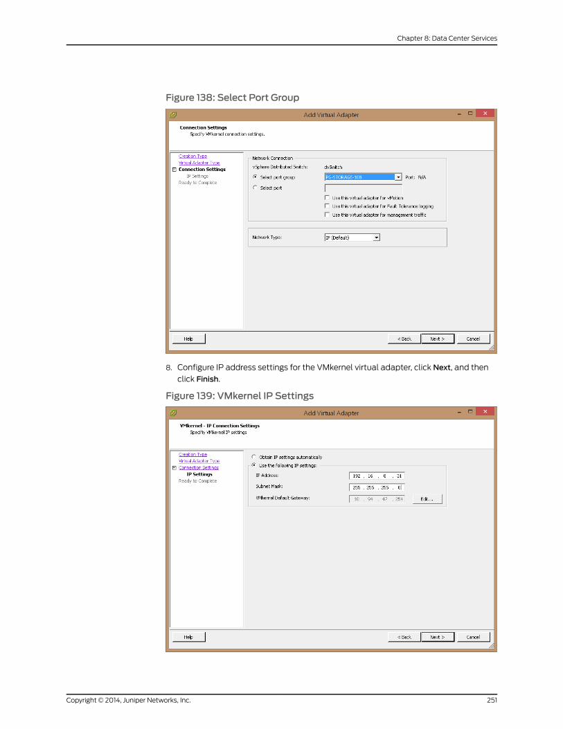
Figure 138: Select Port Group
8. Configure IP address settings for the VMkernel virtual adapter, click Next, and then
click Finish.
Figure 139: VMkernel IP Settings
251Copyright © 2014, Juniper Networks, Inc.
Chapter 8: Data Center Services
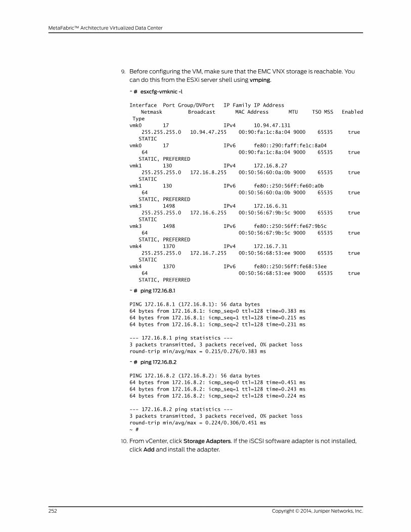
9. Before configuring the VM, make sure that the EMC VNX storage is reachable. You
can do this from the ESXi server shell using vmping.
~ # esxcfg-vmknic -l
Interface Port Group/DVPort IP Family IP Address Netmask Broadcast MAC Address MTU TSO MSS Enabled Type vmk0 17 IPv4 10.94.47.131 255.255.255.0 10.94.47.255 00:90:fa:1c:8a:04 9000 65535 true STATIC vmk0 17 IPv6 fe80::290:faff:fe1c:8a04 64 00:90:fa:1c:8a:04 9000 65535 true STATIC, PREFERRED vmk1 130 IPv4 172.16.8.27 255.255.255.0 172.16.8.255 00:50:56:60:0a:0b 9000 65535 true STATIC vmk1 130 IPv6 fe80::250:56ff:fe60:a0b 64 00:50:56:60:0a:0b 9000 65535 true STATIC, PREFERRED vmk3 1498 IPv4 172.16.6.31 255.255.255.0 172.16.6.255 00:50:56:67:9b:5c 9000 65535 true STATIC vmk3 1498 IPv6 fe80::250:56ff:fe67:9b5c 64 00:50:56:67:9b:5c 9000 65535 true STATIC, PREFERRED vmk4 1370 IPv4 172.16.7.31 255.255.255.0 172.16.7.255 00:50:56:68:53:ee 9000 65535 true STATIC vmk4 1370 IPv6 fe80::250:56ff:fe68:53ee 64 00:50:56:68:53:ee 9000 65535 true STATIC, PREFERRED
~ # ping 172.16.8.1
PING 172.16.8.1 (172.16.8.1): 56 data bytes64 bytes from 172.16.8.1: icmp_seq=0 ttl=128 time=0.383 ms64 bytes from 172.16.8.1: icmp_seq=1 ttl=128 time=0.215 ms64 bytes from 172.16.8.1: icmp_seq=2 ttl=128 time=0.231 ms
--- 172.16.8.1 ping statistics ---3 packets transmitted, 3 packets received, 0% packet lossround-trip min/avg/max = 0.215/0.276/0.383 ms
~ # ping 172.16.8.2
PING 172.16.8.2 (172.16.8.2): 56 data bytes64 bytes from 172.16.8.2: icmp_seq=0 ttl=128 time=0.451 ms64 bytes from 172.16.8.2: icmp_seq=1 ttl=128 time=0.243 ms64 bytes from 172.16.8.2: icmp_seq=2 ttl=128 time=0.224 ms
--- 172.16.8.2 ping statistics ---3 packets transmitted, 3 packets received, 0% packet lossround-trip min/avg/max = 0.224/0.306/0.451 ms~ #
10. From vCenter, click Storage Adapters. If the iSCSI software adapter is not installed,
click Add and install the adapter.
Copyright © 2014, Juniper Networks, Inc.252
MetaFabric™ Architecture Virtualized Data Center

Figure 140: Install iSCSI Software Adapter
11. Once installed, right-click the iSCSI softwareadapter andselectProperties. You should
see that the software is enabled.
Figure 141: iSCSI Initiator Is Enabled
12. Click the Network Configuration tab to verify that the storage is configured and
connected.
253Copyright © 2014, Juniper Networks, Inc.
Chapter 8: Data Center Services

Figure 142: iSCSI Initiator Network Configuration
13. Click the Dynamic Discovery tab and click Add. Enter the IP and port of your EMC VNX
storage.
Copyright © 2014, Juniper Networks, Inc.254
MetaFabric™ Architecture Virtualized Data Center

Figure 143: Add iSCSI Server Location in Dynamic Discovery
14. ClickOK and Close. When prompted to rescan the HBA, click Yes. You see a LUN
presented on the server.
Figure 144: LUN Present on the Server
15. From the vSphere client, select the Exchange-Logs server and Add Storage.
255Copyright © 2014, Juniper Networks, Inc.
Chapter 8: Data Center Services
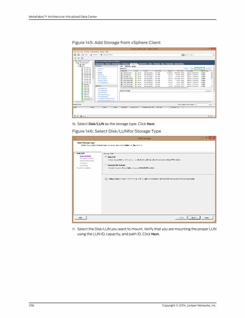
Figure 145: Add Storage from vSphere Client
16. Select Disk/LUN as the storage type. Click Next.
Figure 146: Select Disk/LUNfor Storage Type
17. Select the Disk/LUN youwant tomount. Verify that you aremounting the proper LUN
using the LUN ID, capacity, and path ID. Click Next.
Copyright © 2014, Juniper Networks, Inc.256
MetaFabric™ Architecture Virtualized Data Center

Figure 147: Select LUN toMount
18. Select VMFS 5.0which is supported in ESXi 5.1. VMFS 5.0 also supports 2TB+. Click
Next.
Figure 148: Select VMFS-5 as a File System
19. Notice that the hard disk is blank under Current Disk Layout. Click Next.
20.Enter a name for the datastore and click Next.
257Copyright © 2014, Juniper Networks, Inc.
Chapter 8: Data Center Services

Figure 149: Name the Datastore
21. Select themaximumcapacity for thisdatastore. (Themaximumcapacity is thedefault
option.) Click Next and Finish. Click Properties on the created datastore to see an
output similar to the following
Figure 150: Datastore Creation Complete
Copyright © 2014, Juniper Networks, Inc.258
MetaFabric™ Architecture Virtualized Data Center

Configuring vMotion Support
This implementation supports vMotion. Wemust make sure, however, that in EMC
Unisphere, all ESXi hosts have been given access to all LUNs. Once this is configured and
enabled, other hosts will attempt to mount the same datastore once you start rescan
on the other hosts. Similarly, all LUNsmust bemounted on all appropriate ESXi hosts
as this is a requirement for vMotion. Network and storagemust be provisioned to all ESXi
hosts. Thenext sectionwill showhowtoaddnewVMoraddanexistingVMforapplication
scaling. This guide does not cover the installation or configuration of the Exchange
applications.
To configure vMotion support for an ESXi host, follow these steps:
1. Log in to Virtual Center Server using vSphere client.
2. Select the cluster to create a new VM. Click Create a new virtual machine.
Figure 151: Create NewVM
3. Click Typical and then click Next.
259Copyright © 2014, Juniper Networks, Inc.
Chapter 8: Data Center Services

Figure 152: VM Type
4. Enter a name for your virtual machine. Click Next.
Copyright © 2014, Juniper Networks, Inc.260
MetaFabric™ Architecture Virtualized Data Center

Figure 153: Give the VM aName
5. Tomount storage to the VM, select the datastore POD1-VMFS-LUN3created earlier,
and click, Next.
261Copyright © 2014, Juniper Networks, Inc.
Chapter 8: Data Center Services

Figure 154: Select Storage
6. Select an operating system (Windows 2012 64-bit was used in this scenario). Click
Next.
Copyright © 2014, Juniper Networks, Inc.262
MetaFabric™ Architecture Virtualized Data Center
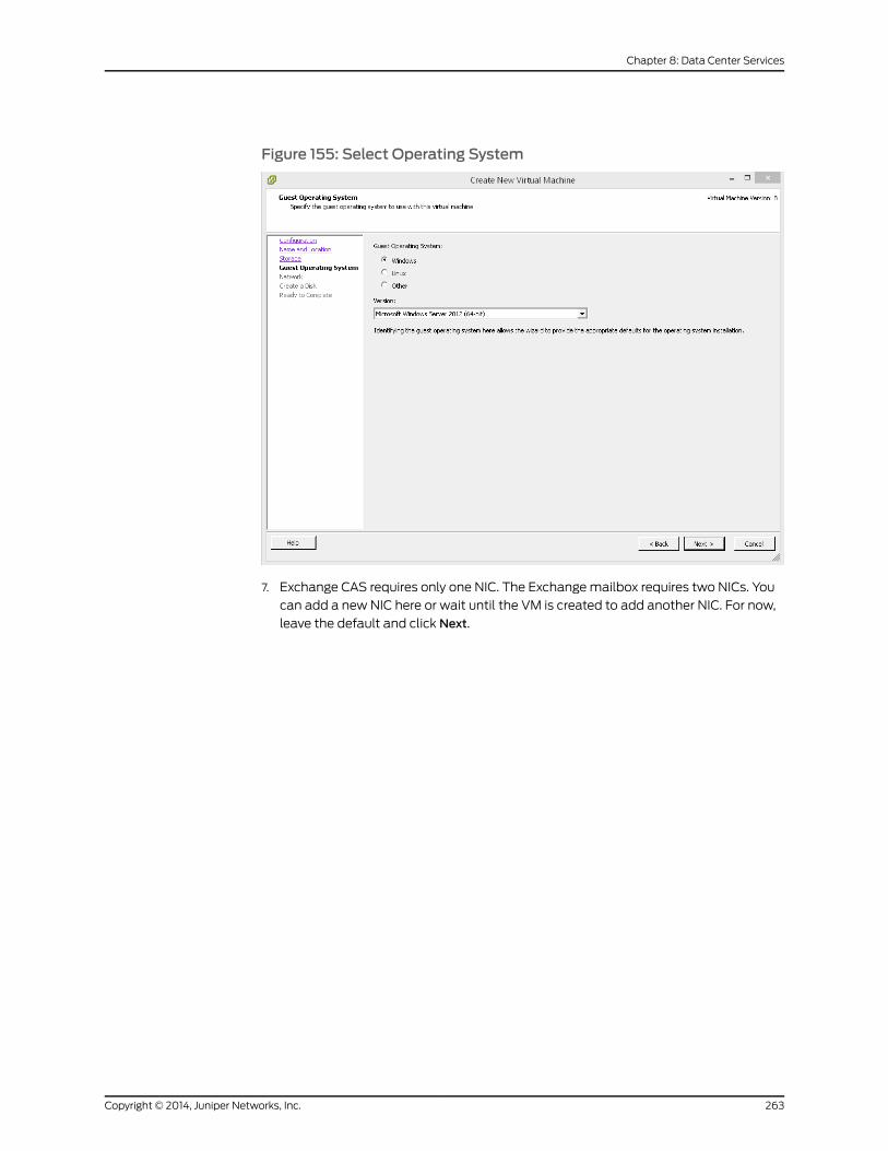
Figure 155: Select Operating System
7. Exchange CAS requires only one NIC. The Exchangemailbox requires two NICs. You
can add a new NIC here or wait until the VM is created to add another NIC. For now,
leave the default and click Next.
263Copyright © 2014, Juniper Networks, Inc.
Chapter 8: Data Center Services

Figure 156: Configure Network
8. Select the virtual disk size for the operating system. (This will be the C:/ drive in the
OS.) Click Finish.
Copyright © 2014, Juniper Networks, Inc.264
MetaFabric™ Architecture Virtualized Data Center
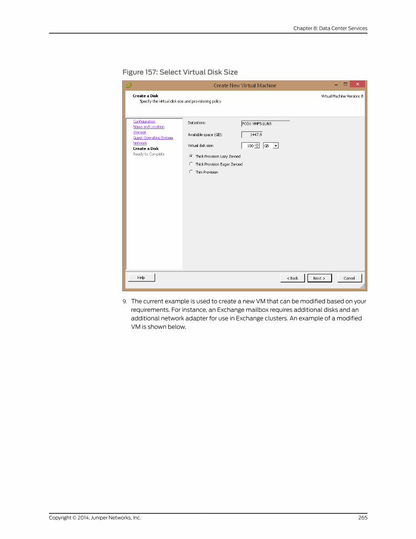
Figure 157: Select Virtual Disk Size
9. The current example is used to create a new VM that can bemodified based on your
requirements. For instance, an Exchangemailbox requires additional disks and an
additional network adapter for use in Exchange clusters. An example of a modified
VM is shown below.
265Copyright © 2014, Juniper Networks, Inc.
Chapter 8: Data Center Services
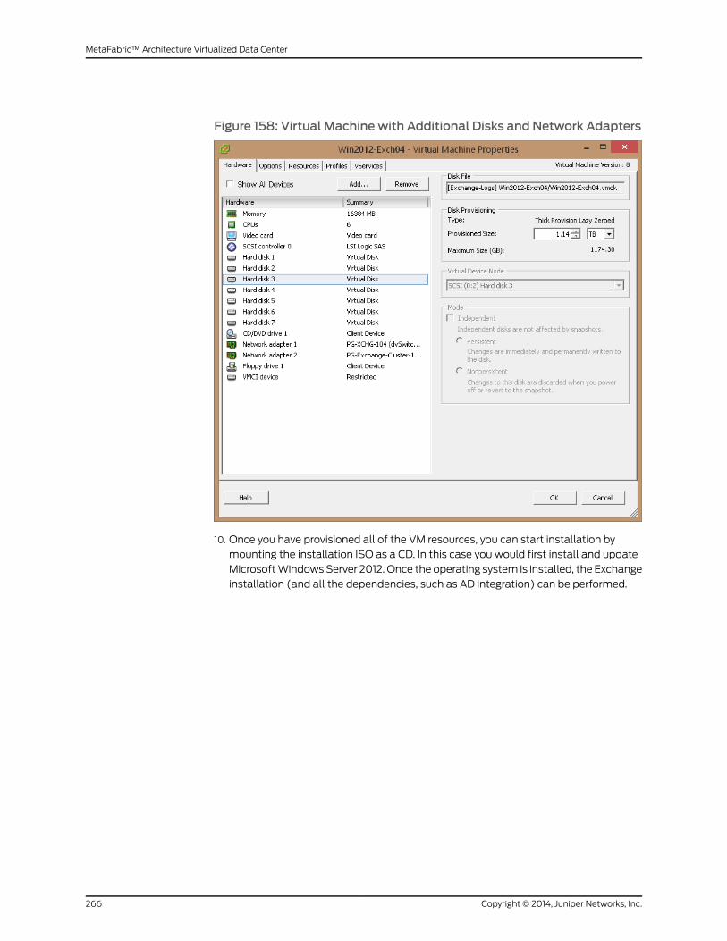
Figure 158: Virtual Machine with Additional Disks and Network Adapters
10. Once you have provisioned all of the VM resources, you can start installation by
mounting the installation ISO as a CD. In this case you would first install and update
MicrosoftWindowsServer 2012. Once the operating system is installed, the Exchange
installation (and all the dependencies, such as AD integration) can be performed.
Copyright © 2014, Juniper Networks, Inc.266
MetaFabric™ Architecture Virtualized Data Center

CHAPTER 9
NetworkManagement andOrchestration
The following section covers the configurationof services in theVirtualized ITDataCenter.
The areas covered by this chapter include:
• Junos Space
• Overview
• Configure Junos Space and Network Director
• Implement and configure Security Director
• Overview on page 267
• Configuring Security Director on page 287
Overview
The MetaFabric 1.0 solution lab employed Junos Space along with Network Director (a
Junos Space application) in the provisioning and testing of the solution. Specifically,
Junos Space Release 13.1R1 was used along with Network Director 1.5 (with Virtual View
application) for implementation andmanagement of the network. Virtualmachine (VM)
orchestration was also controlled by the Junos Space implementation.
Junos Space is installed on a VM on the IBM 3750 standalone server and serves the
out-of-band (OOB)management role in the data center topology. Two IBM3750 servers
are configured in a single ESX cluster for redundancy and fault tolerance. In case of one
ESXnode failure, the JunosSpaceVMcanbemoved to theotherESXi hostusingvMotion.
NetworkDirector 1.5 includessupport for theQFX3000-Msystemtoprovisionandmonitor
the entire solution. Network Director Virtual View is enabled for orchestration to enable
tracking of VMmovement within the data center test topology.
Security Director is also a component of themanagement and orchestration of the data
center solution. Security Director is an application installed on Junos Space. It is used to
configure and operate the perimeter security elements of the solution.
Topology
Figure 159 on page 268 illustrates the topology of the out-of-band (OOB)management
network tested in the MetaFabric 1.0 lab.
267Copyright © 2014, Juniper Networks, Inc.
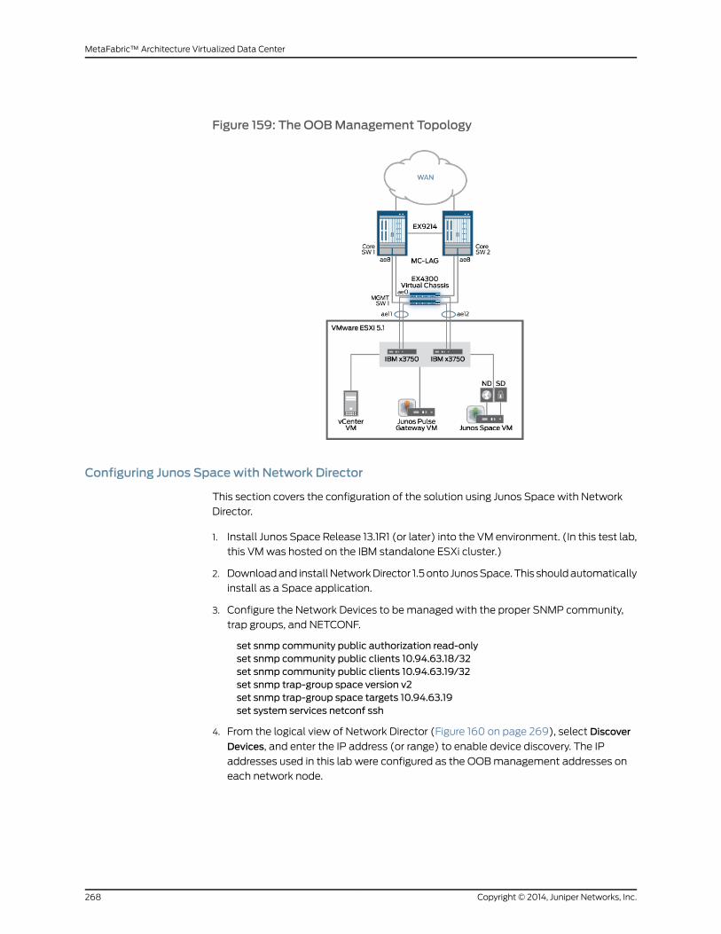
Figure 159: The OOBManagement Topology
Configuring Junos Spacewith Network Director
This section covers the configuration of the solution using Junos Space with Network
Director.
1. Install Junos Space Release 13.1R1 (or later) into the VM environment. (In this test lab,
this VMwas hosted on the IBM standalone ESXi cluster.)
2. Downloadand installNetworkDirector 1.5onto JunosSpace.This shouldautomatically
install as a Space application.
3. Configure the Network Devices to bemanaged with the proper SNMP community,
trap groups, and NETCONF.
set snmp community public authorization read-onlyset snmp community public clients 10.94.63.18/32set snmp community public clients 10.94.63.19/32set snmp trap-group space version v2set snmp trap-group space targets 10.94.63.19set system services netconf ssh
4. From the logical view of Network Director (Figure 160 on page 269), select Discover
Devices, and enter the IP address (or range) to enable device discovery. The IP
addresses used in this lab were configured as the OOBmanagement addresses on
each network node.
Copyright © 2014, Juniper Networks, Inc.268
MetaFabric™ Architecture Virtualized Data Center
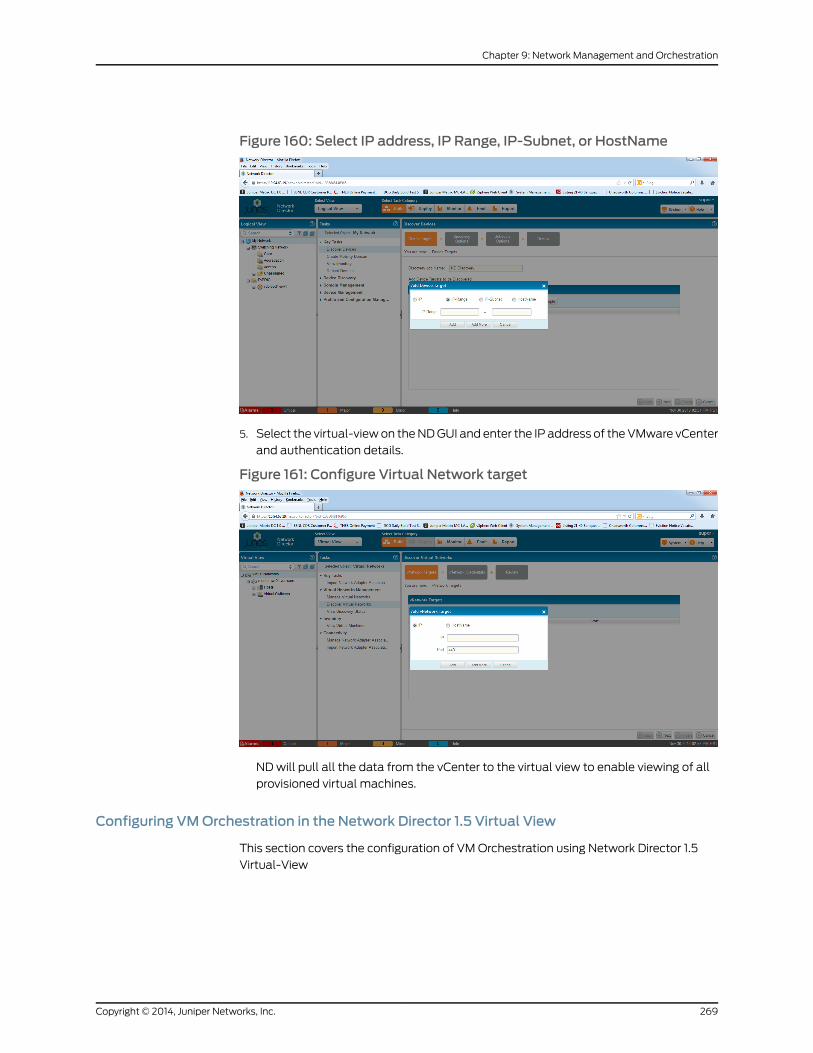
Figure 160: Select IP address, IP Range, IP-Subnet, or HostName
5. Select the virtual-viewon theNDGUI and enter the IP address of theVMware vCenter
and authentication details.
Figure 161: Configure Virtual Network target
NDwill pull all the data from the vCenter to the virtual view to enable viewing of all
provisioned virtual machines.
Configuring VMOrchestration in the Network Director 1.5 Virtual View
This section covers the configuration of VMOrchestration using Network Director 1.5
Virtual-View
269Copyright © 2014, Juniper Networks, Inc.
Chapter 9: Network Management and Orchestration
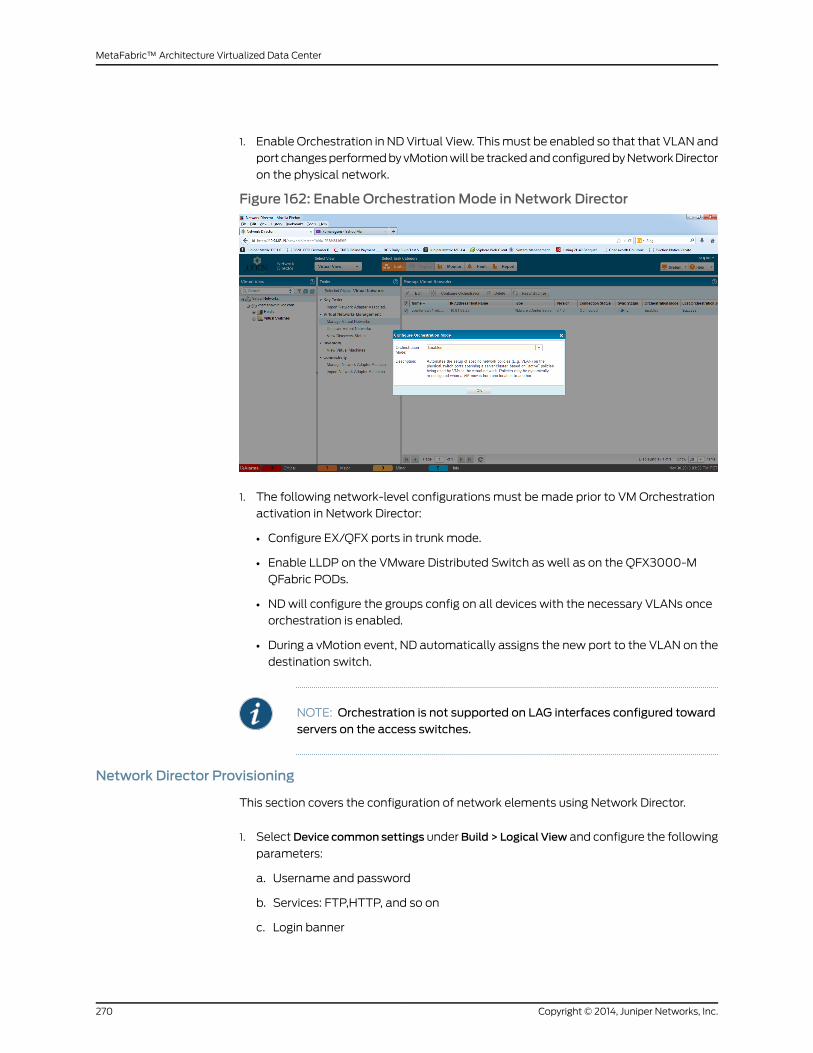
1. Enable Orchestration in NDVirtual View. Thismust be enabled so that that VLAN and
port changesperformedbyvMotionwill be trackedandconfiguredbyNetworkDirector
on the physical network.
Figure 162: Enable OrchestrationMode in Network Director
1. The following network-level configurations must bemade prior to VMOrchestration
activation in Network Director:
• Configure EX/QFX ports in trunk mode.
• Enable LLDP on the VMware Distributed Switch as well as on the QFX3000-M
QFabric PODs.
• NDwill configure the groups config on all devices with the necessary VLANs once
orchestration is enabled.
• During a vMotion event, ND automatically assigns the new port to the VLAN on the
destination switch.
NOTE: Orchestration is not supported on LAG interfaces configured towardservers on the access switches.
Network Director Provisioning
This section covers the configuration of network elements using Network Director.
1. SelectDevice common settings underBuild > Logical View and configure the following
parameters:
a. Username and password
b. Services: FTP,HTTP, and so on
c. Login banner
Copyright © 2014, Juniper Networks, Inc.270
MetaFabric™ Architecture Virtualized Data Center
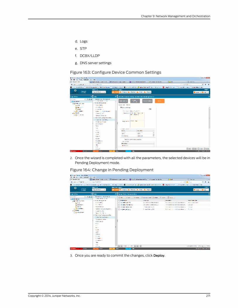
d. Logs
e. STP
f. DCBX/LLDP
g. DNS server settings
Figure 163: Configure Device Common Settings
2. Once the wizard is completed with all the parameters, the selected devices will be in
Pending Deployment mode.
Figure 164: Change in Pending Deployment
3. Once you are ready to commit the changes, click Deploy.
271Copyright © 2014, Juniper Networks, Inc.
Chapter 9: Network Management and Orchestration
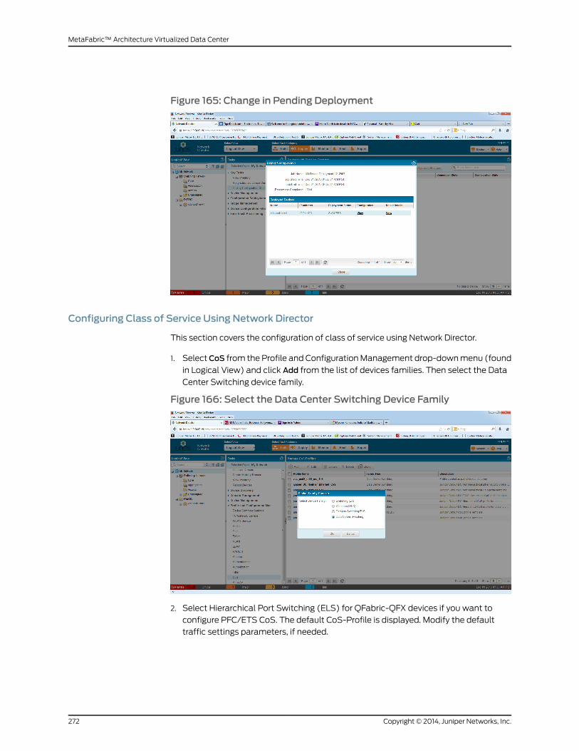
Figure 165: Change in Pending Deployment
Configuring Class of Service Using Network Director
This section covers the configuration of class of service using Network Director.
1. SelectCoS from the Profile and ConfigurationManagement drop-downmenu (found
in Logical View) and click Add from the list of devices families. Then select the Data
Center Switching device family.
Figure 166: Select the Data Center Switching Device Family
2. Select Hierarchical Port Switching (ELS) for QFabric-QFX devices if you want to
configure PFC/ETS CoS. The default CoS-Profile is displayed. Modify the default
traffic settings parameters, if needed.
Copyright © 2014, Juniper Networks, Inc.272
MetaFabric™ Architecture Virtualized Data Center

Figure 167: Select the Profile "Hierarchal Port Switching (ELS)"
3. Enable the PFC code point and queue for NO-LOSS behavior. In this example, Queue
3 is chosen as the no-loss queue.
Figure 168: Enable PFC Code-point and Queue for NO-LOSS Behavior
4. This CoS profile will be referenced while creating port configuration in the next steps.
273Copyright © 2014, Juniper Networks, Inc.
Chapter 9: Network Management and Orchestration

Figure 169: COS Profile Deployed
Creating VLANs Using Network Director
This section covers the creation and installation of VLANs using Network Director.
1. Select a VLAN and enter the VLAN-ID and VLAN-Name (ND-Test-VLAN in this
example).
Figure 170: Create VLAN-ID and VLANName
2. Click Next to go to Advanced Settings and configure Layer 2 filters and MAC address
move limits.
Copyright © 2014, Juniper Networks, Inc.274
MetaFabric™ Architecture Virtualized Data Center
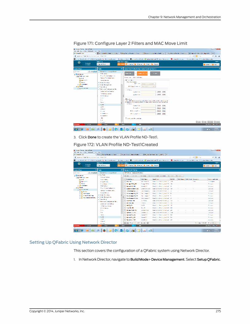
Figure 171: Configure Layer 2 Filters andMACMove Limit
3. Click Done to create the VLAN Profile ND-Test1.
Figure 172: VLAN Profile ND-Test1Created
Setting UpQFabric Using Network Director
This section covers the configuration of a QFabric system using Network Director.
1. InNetworkDirector, navigate toBuildMode>DeviceManagement. SelectSetupQFabric.
275Copyright © 2014, Juniper Networks, Inc.
Chapter 9: Network Management and Orchestration

Figure 173: Select Setup QFabric
2. Configure aliases for the node and interconnect devices by clicking the default aliases
shown in the GUI as NODE-1 and NODE-2.
Figure 174: Configure Device Aliases
3. Configure node devices in a redundant server node group (RSNG), using the aliases
configured in Step 2 (NODE-1 and NODE-2).
Copyright © 2014, Juniper Networks, Inc.276
MetaFabric™ Architecture Virtualized Data Center
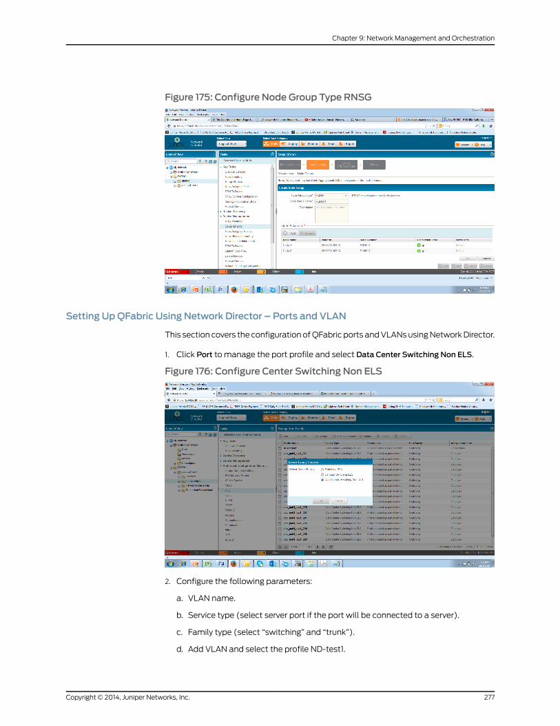
Figure 175: Configure Node Group Type RNSG
Setting UpQFabric Using Network Director – Ports and VLAN
This section covers the configuration ofQFabric ports andVLANsusingNetworkDirector.
1. Click Port to manage the port profile and select Data Center Switching Non ELS.
Figure 176: Configure Center Switching Non ELS
2. Configure the following parameters:
a. VLAN name.
b. Service type (select server port if the port will be connected to a server).
c. Family type (select “switching” and “trunk”).
d. Add VLAN and select the profile ND-test1.
277Copyright © 2014, Juniper Networks, Inc.
Chapter 9: Network Management and Orchestration

Figure 177: Configure VLAN Service, Port, CoS, and so on
3. Click Done to create the port profile.
Figure 178: Port Profile Created (NDTestport)
4. Assign the port profile to the physical interface. ClickAssign to list the available ports.
Copyright © 2014, Juniper Networks, Inc.278
MetaFabric™ Architecture Virtualized Data Center
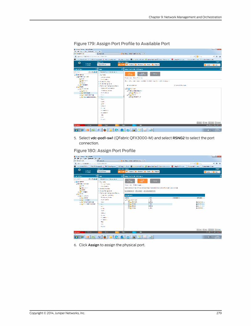
Figure 179: Assign Port Profile to Available Port
5. Select vdc-pod1-sw1 (QFabric QFX3000-M) and select RSNG2 to select the port
connection.
Figure 180: Assign Port Profile
6. Click Assign to assign the physical port.
279Copyright © 2014, Juniper Networks, Inc.
Chapter 9: Network Management and Orchestration
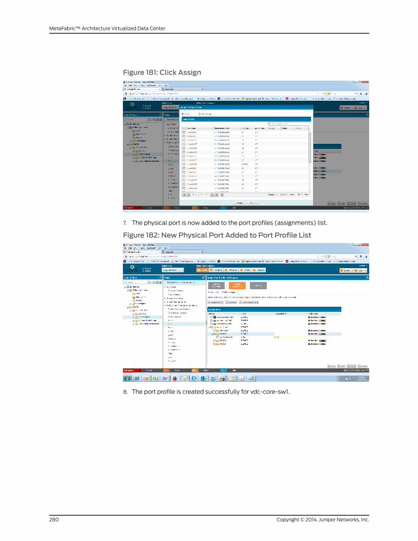
Figure 181: Click Assign
7. The physical port is now added to the port profiles (assignments) list.
Figure 182: New Physical Port Added to Port Profile List
8. The port profile is created successfully for vdc-core-sw1.
Copyright © 2014, Juniper Networks, Inc.280
MetaFabric™ Architecture Virtualized Data Center

Figure 183: Port Profile Created Successfully
9. Deploy the port profile to the vdc-core-sw1. Go to Deploy Mode and check pending
configuration deployments.
Figure 184: Check to Confirm Port Profile Is Pending
10. Deploy the changes to the device using the Deploy Now option.
281Copyright © 2014, Juniper Networks, Inc.
Chapter 9: Network Management and Orchestration

Figure 185: Select Deploy Now
Setting Up a QFabric SystemUsing Network Director – Create Link Aggregation Groups
This section covers the configuration of LAGs by using Network Director.
NOTE: MC-LAG is only supported forQFX standalone systems. (This featurewas not supported in the MetaFabric 1.0 test bed.)
1. Select Build > DeviceManagement >Manage Port Groups. Select Add new port group.
Figure 186: Add NewPort Group
2. Select a device from the left pane, then clickSelectDevices to select the LAGmember
links.
Copyright © 2014, Juniper Networks, Inc.282
MetaFabric™ Architecture Virtualized Data Center

Figure 187: Select Devices to Add as LAGMember Links
Selected links are shown below, which will belong to a LAG (port group).
Figure 188: Links Selected to Be LAGMember Links
Network Director – Downloading and Upgrading Software Images
This section covers software and imagemanagement using Network Director.
283Copyright © 2014, Juniper Networks, Inc.
Chapter 9: Network Management and Orchestration

1. Select Deploy > ImageManagement > .
Figure 189: Network Director Image Repository
2. Browse and select the image you would like to upload to the ND repository. Select
Upload.
Figure 190: Image Staging on Network Director
3. Deploy the downloaded image to the physical devices. Select one of the following
three options:
a. Staging only (Download to remote device but do not install)
b. Upgrade only (Install previously staged image to device)
c. Staging and Upgrade (Download and install image)
Copyright © 2014, Juniper Networks, Inc.284
MetaFabric™ Architecture Virtualized Data Center

Figure 191: Stage Image to Device for Install or for Later Installation
4. Click “Next” to select the devices for the upgrade and select the downloaded image
per device family
Figure 192: Select Image to Stage to Remote Device
Network Director –Monitoring the QFabric System
This section covers software and imagemanagement using Network Director.
285Copyright © 2014, Juniper Networks, Inc.
Chapter 9: Network Management and Orchestration

1. SelectMonitor>SelectDevices>vdc-pod1-sw1. This opensup thedashboard toenable
viewing of the QFabric System status.
Figure 193: Device Dashboard
2. Select Traffic to see traffic statistics on the QFabric system.
Figure 194: QFabric Traffic Statistics
3. Select Equipment to enable viewing of CPU andmemory utilization.
Copyright © 2014, Juniper Networks, Inc.286
MetaFabric™ Architecture Virtualized Data Center

Figure 195: Hardware Dashboard
4. Click Run Fabric Analyzer (in the right pane) to get the fabric internal link status.
Figure 196: Confirmation of Run Fabric Analyzer Operation
Configuring Security Director
• Overview on page 287
Overview
Junos Space Security Director is one of the Junos Spacemanagement applications and
helpsorganizations improve the reach, ease, andaccuracyof securitypolicyadministration
with a scalable, GUI-basedmanagement tool. It automates security provisioning through
one centralizedWeb-based interface to help administrators manage all phases of the
287Copyright © 2014, Juniper Networks, Inc.
Chapter 9: Network Management and Orchestration

security policy life cyclemore quickly and intuitively, from policy creation to remediation.
Security Director provides the following management efficiencies:
1. Scale security policy acrossmultiple Juniper Networks SRXSeries ServicesGateways,
or managemultiple logical system (LSYS) instances on a single SRX Series device.
2. Centrally configure andmanage application security (for example, AppSecure),
firewall, VPN, IPS,andNATsecuritypolicy throughonescalablemanagement interface.
3. Define and enforce policies for controlling usage of specific applications such as
Facebook, instant messaging, and embedded social networking widgets through
included AppFWmanagement.
4. Reuse security policies within Junos Space Security Director for improved security
enforcement accuracy, consistency, and compliance.
5. Build the infrastructure for furthermanagement innovationacross thenetwork through
open and secure Junos Space Network Management Platform integration.
When you finish creating and verifying your security configurations, you canpublish these
configurationsandkeep themready tobepushed to the securitydevices. SecurityDirector
helps you deploy all the security configurations to the devices all at once by providing a
single interface that is intuitive. You can select all security devices that you are using on
the network and push all security configurations to these devices.
The Security Director application is divided into sevenworkspaces, which include Object
Builder, Firewall Policy, NAT Policy, VPN, Downloads, IPS Management, and Security
Director Devices.
• Object Builder—Workspace to create objects used for firewall policy, NAT policy, and
VPN configurations.
• FirewallPolicy—Workspace tocreateandpublish firewall policiesonsupporteddevices.
• NAT Policy—Workspace to create and publish NAT policies on supported devices.
• VPN—Workspace to create site-to-site, hub-and-spoke, and full-mesh IPsec VPNs.
• Downloads—Workspace to download and install signatures.
• IPS Management—Workspace to create andmanage IPS signatures, signature sets,
and IPS policies.
• Security Director Devices—Workspace to update the configurations on the devices.
Discovery and Basic Configuration Using Security Director
Discovery is the process of finding a device and then synchronizing the device inventory
and configuration with the Junos Space database. To use device discovery, Junos Space
must be able to connect to the device.
Copyright © 2014, Juniper Networks, Inc.288
MetaFabric™ Architecture Virtualized Data Center
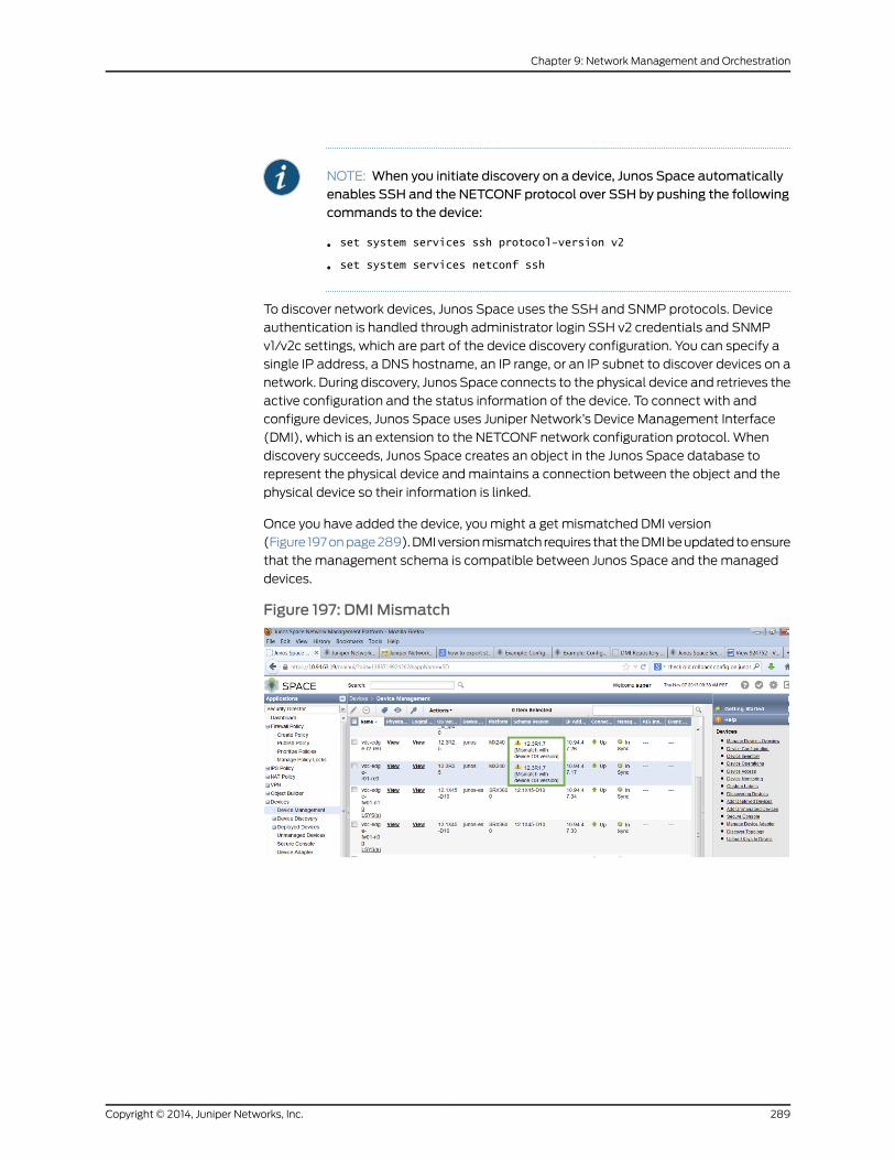
NOTE: When you initiate discovery on a device, Junos Space automaticallyenables SSH and the NETCONF protocol over SSH by pushing the followingcommands to the device:
• set system services ssh protocol-version v2
• set system services netconf ssh
To discover network devices, Junos Space uses the SSH and SNMP protocols. Device
authentication is handled through administrator login SSH v2 credentials and SNMP
v1/v2c settings, which are part of the device discovery configuration. You can specify a
single IP address, a DNS hostname, an IP range, or an IP subnet to discover devices on a
network. During discovery, Junos Space connects to the physical device and retrieves the
active configuration and the status information of the device. To connect with and
configure devices, Junos Space uses Juniper Network’s Device Management Interface
(DMI), which is an extension to the NETCONF network configuration protocol. When
discovery succeeds, Junos Space creates an object in the Junos Space database to
represent the physical device andmaintains a connection between the object and the
physical device so their information is linked.
Once you have added the device, youmight a get mismatched DMI version
(Figure 197onpage289).DMIversionmismatch requires that theDMIbeupdatedtoensure
that the management schema is compatible between Junos Space and themanaged
devices.
Figure 197: DMI Mismatch
289Copyright © 2014, Juniper Networks, Inc.
Chapter 9: Network Management and Orchestration
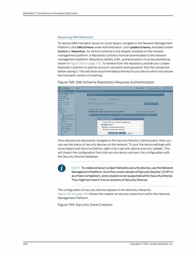
Resolving DMIMismatch
To resolve DMI mismatch issues on Junos Space, navigate to the Network Management
Platform, clickDMISchema under Administration, clickUpdateSchema, and select either
Archive or Repository. An Archive schema is one already installed on the network
management platform. A Repository schemamust be downloaded to the network
management platform. Repository details (URL, authentication) must be provided as
shown in Figure 198 on page 290. To retrieve from the repository, provide your Juniper
Networks customer or partner account username and password. Test the connection
before saving it. Thiswill show recommended schemas for your devicewhichwill resolve
the mismatch version of schemas.
Figure 198: DMI Schema Repository Requires Authentication
Once devices are discovered, navigate to the Security Director’s Device pane. Here, you
can see the status of security devices on the network. To sync the device settings with
Junos Space and Security Director, right-click a security device and click Update. This
will import the configuration from the security device and sync the configuration with
the Security Director database.
NOTE: Tocreatezoneson JuniperNetworkssecuritydevices, use theNetworkManagementPlatform.Asof thecurrent versionofSecurityDirector (13.1P1.14asof test completion), zonecreation isnot supportedwithinSecurityDirector.This might be fixed in future versions of Security Director.
The configuration of security devices appears in the directory hierarchy.
Figure 199 on page 290 shows the creation of security zones fromwithin the Network
Management Platform.
Figure 199: Security Zone Creation
Copyright © 2014, Juniper Networks, Inc.290
MetaFabric™ Architecture Virtualized Data Center

Object Builder (Using Security Director)
Use the Object Builder workspace in Security Director to create objects used by firewall,
VPN, and NAT policies. These objects are stored in the Junos Space database. You can
reuse these objects with multiple security policies, VPNs, and NAT policies across an
entire device or network footprint. This approachmakes the design of services more
structured and avoids the need to create the objects during the service design. You can
use the Object Builder workspace to create, modify, clone, and delete the following
objects:
• Addresses and address groups
• Services and service groups
• Application signatures
• Extranet devices
• NAT pools
• Policy profiles
• VPN profiles
• Variables
• Template and template definitions
Figure 200 on page 292 is an example of address object creation using Security Director.
Custom services, NAT pools, devices, and so on can be created in a similar fashion. To
create an object, follow these basic steps:
1. Go to the Object Builder under Security Director.
2. Go to Addresses.
3. Click on the Plus sign to create a new address on the right side.
4. Click on the Pen side to modify an existing address.
291Copyright © 2014, Juniper Networks, Inc.
Chapter 9: Network Management and Orchestration
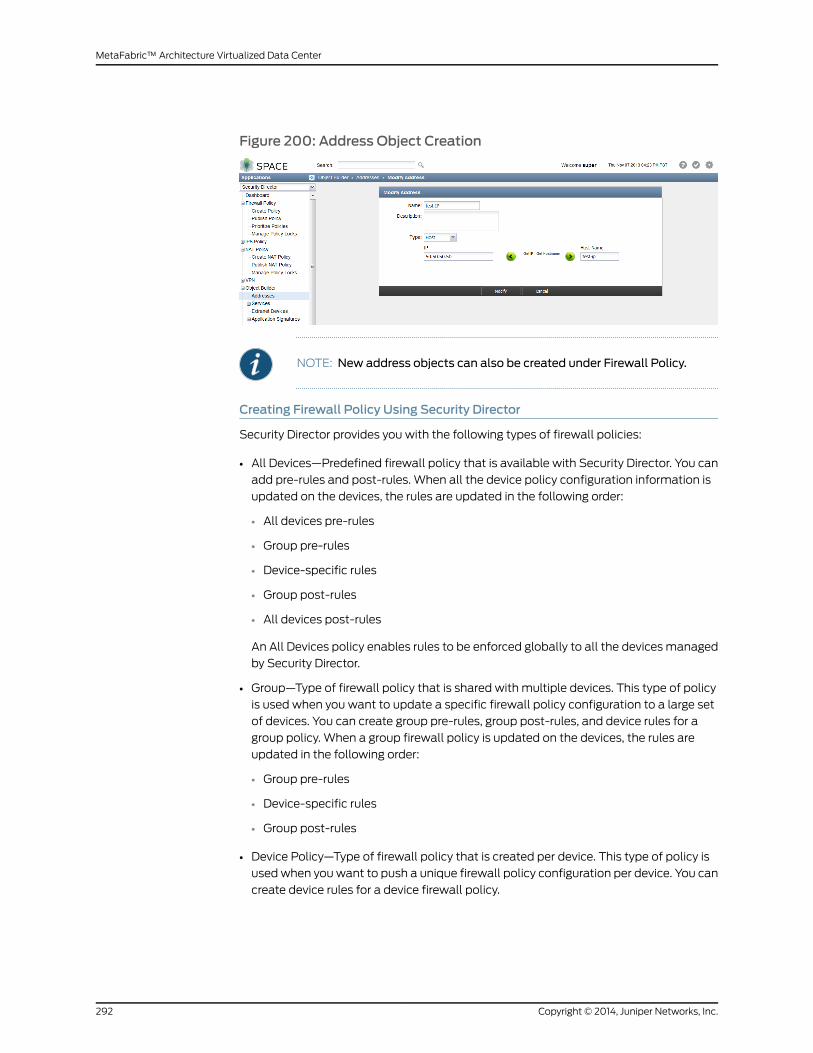
Figure 200: Address Object Creation
NOTE: New address objects can also be created under Firewall Policy.
Creating Firewall Policy Using Security Director
Security Director provides you with the following types of firewall policies:
• All Devices—Predefined firewall policy that is available with Security Director. You can
add pre-rules and post-rules. When all the device policy configuration information is
updated on the devices, the rules are updated in the following order:
• All devices pre-rules
• Group pre-rules
• Device-specific rules
• Group post-rules
• All devices post-rules
An All Devices policy enables rules to be enforced globally to all the devices managed
by Security Director.
• Group—Type of firewall policy that is shared with multiple devices. This type of policy
is used when you want to update a specific firewall policy configuration to a large set
of devices. You can create group pre-rules, group post-rules, and device rules for a
group policy. When a group firewall policy is updated on the devices, the rules are
updated in the following order:
• Group pre-rules
• Device-specific rules
• Group post-rules
• Device Policy—Type of firewall policy that is created per device. This type of policy is
usedwhen youwant to push a unique firewall policy configuration per device. You can
create device rules for a device firewall policy.
Copyright © 2014, Juniper Networks, Inc.292
MetaFabric™ Architecture Virtualized Data Center

• Device-Exception Policy—Type of firewall policy that is created when a device is
removed from a group policy.
• Global Policy—Global Policy Rules are enforced regardless of ingress or egress zones;
they are enforced on any device transit. Any objects defined in the Global Policy Rules
must be defined in the global address book.
The basic settings of a firewall policy are obtained from the policy profile in Security
Director. The basic settings include log options, firewall authentication schemes, and
traffic redirection options.
All device pre-rules and post-rules are applicable to all security devices. Once pre-rules
are published, these rules are applied to all managed security devices. Security Policy
post-rulesarepublished to thesecuritydeviceandcanbeused tooverwritedevice-specific
post-rules already deployed on the security device.
The general steps that must be followed to create a new security policy are:
1. Under Firewall policy, click to create a new policy.
2. Create the policy created for a device or a group
3. Once the policy is created, assign the policy to the device.
4. Click on Create.
The new policy created is displayed in the right pane. An option is also included to save
the policy and validate the configuration (ensure that the configuration does not contain
errors). After policy creation, you need to publish or publish and update the policy to the
security device.
• Publish policy will push the policy to the Junos Space database. This will also validate
the configuration.
• Publish and update will push the policy to the security device. This is often preferred
as ameans of provisioningmultiple devices during shortmaintenancewindows as this
feature publishes the device to the Junos Space database, validates that the
configurationwill have no errors, and then updates themanaged security devices with
the new configuration.
Figure201onpage294showsanexampleofpolicycreationafter importingaconfiguration
from amanaged security device. The steps that were followed in this example are:
1. Navigate to the Firewall policy under Security Director.
2. The right pane shows a list of policy name and all existing policies.
3. Click on Lock to lock the policy. (Policy must be locked to edit.)
4. Click on the plus (+) sign to add a new rule or the (-) sign to delete an existing rule. In
this example, we are adding a new rule (Test-1). Click the +sign.
293Copyright © 2014, Juniper Networks, Inc.
Chapter 9: Network Management and Orchestration

Figure 201: New Rule Created (Test-1)
5. Whilemodifying theaddress, select anaddress fromtheexistingaddressbookor click
on the plus (+) sign to add a new address.
Figure 202: Add NewSource Address to Rule
6. Once you create the rule, use the up or down arrow tomove the rules up or down.
7. Click Save to save the configuration to the Security Director database.
8. To verify the configuration, click Validate.
Creating NAT Policy Using Security Director
Network Address Translation (NAT) is a form of network masquerading that replaces
private IP addresses (or addresses you wish to hide from public routing) with other
addresses (most often a public, routable IP address). NAT can also be used to provide
public access toprivate resources in thedatacenterby translatingapublic IP (an incoming
HTTP GET to aWeb server, for instance) to a private IP address. In Junos OS security
devices, NAT is largely zone-based. A trust zone is a segment of the network where
security measures are applied (sometimes referred to the “inside” of the network). It is
usually assigned to the internal LAN. An untrust zone is most often facing the Internet
(can also be facing any insecure network such as a partner or customer). NATmodifies
the IP addresses of the packets moving between these security zones.
Copyright © 2014, Juniper Networks, Inc.294
MetaFabric™ Architecture Virtualized Data Center

Junos Space Security Director supports three types of NAT:
• Source NAT—Translates the source IP address of a packet leaving the trust zone
(outbound traffic). It translates the traffic originating from the device in the trust zone.
Using source NAT, an internal device can access the network by using the IP addresses
specified in the NAT policy.
• Destination NAT—Translates the destination IP address of a packet entering the trust
zone (inbound traffic). It translates the traffic originating from a device outside the
trust zone. Using destination NAT, an external device can send packets to a hidden
internal device.
• Static NAT—Always translates a private IP address to the same public IP address. It
translates traffic from both sides of the network (both source and destination). For
example, aWeb server with a private IP address can access the Internet using a static,
one-to-one address translation.
Junos Space Security Director provides you with a workflow where you can create and
apply NAT policies on devices in a network. To create a NAT policy:
1. Select Security Director > NAT Policy.
2. Click Create NAT Policy from the left pane. You can create a group policy or a device
policy.
3. Tocreateagrouppolicy, enter nameof thegrouppolicy, adescription, and theassigned
device for which policies have been configured.
You can also search for the devices by entering the device name, device IP address, or
device tag in the Search field in the Select Devices section. The above steps can also be
used to create device NAT policies. The Validate button will check the NAT policies for
errors. If any errors are found during the validation, a red warning icon is shown for the
policy or policies containing errors. In the case of NAT policies, incomplete rules and
duplicate rule names should flag as errors during validation. Please note that an existing
policy must be locked before any changes can be attempted. NAT policies can also be
rearranged (moved up or down) using the arrow keys.
Once you define a NAT policy, it must be published.
To publish a NAT policy:
1. Select Security Director > NAT Policy.
2. Right-click thepolicyon the right side that youwant topublishandclickAssigndevices.
3. Select Schedule at a later time check box if you want to schedule and publish the
configuration later.
4. Click Next.
5. To preview the configuration changes that will be pushed to the device, click View
Configuration in XML format > XML configuration tab.
6. Click Close.
295Copyright © 2014, Juniper Networks, Inc.
Chapter 9: Network Management and Orchestration

7. Click Publish if you want to only publish the configuration.
8. Click Publish and Update if you want to publish and update the devices with the
configuration.
You can view any job under Jobs for the status. Figure 203 on page 296 shows two NAT
policies configured on the selected firewall.
Figure 203: Example NAT Policies in Security Director
JobsWorkspace in Security Director
The Jobsworkspace lets youmonitor the status of all jobs that have been run in all Junos
Space applications. A job is a user-initiated action that is performed on a Junos Space
Network Management Platform object, such as a device, service, or customer. All
scheduled jobs can bemonitored.
Typical jobs in Junos Space Network Management Platform include device discovery,
deploying services, pre-staging devices, and performing functional and configuration
audits. Jobs canbescheduled tooccur immediately or in the future. For all jobs scheduled
in Junos Space Network Management Platform, you can view job status from the Jobs
workspace. JunosSpaceNetworkManagementPlatformmaintainsahistoryof job status
for all scheduled jobs. When a job is scheduled from aworkspace, Junos Space Network
Management Platform assigns a job ID that serves to identify the job (along with the job
type) in the Manage Jobs inventory page.
You can perform the following tasks from the Jobs workspace:
• View status of all scheduled, running, canceled, and completed jobs.
• Retrieve details about the execution of a specific job.
• View statistics about average execution times for jobs, types of jobs that are run, and
success rate
• Cancel a scheduled job or in-progress job (when the job has stalled and is preventing
other jobs from starting).
• Archiveold jobsandpurge themfromthe JunosSpaceNetworkManagementPlatform
database.
Copyright © 2014, Juniper Networks, Inc.296
MetaFabric™ Architecture Virtualized Data Center

Audit Logs in Security Director
Audit logs provide a record of Junos Space Network Management Platform login history
and user-initiated tasks that are performed from the user interface. From the Audit Logs
workspace, youcanmonitoruser login/logoutactivityover time, trackdevicemanagement
tasks, view services thatwere provisioned on devices, and so forth. Junos SpaceNetwork
Management Platform audit logging does not record non-user initiated activities, such
as device-driven activities, and is not designed for debugging purposes. User-initiated
changes made from the Junos Space CLI are logged but are not recorded in audit logs.
Administrators can sort and filter on audit logs to determinewhich users performedwhat
actions on what objects at what time. For example, an Audit Log administrator can use
audit log filtering to track the user accounts that were added on a specific date, track
configuration changes across a particular type of device, view services that were
provisioned on specific devices, or monitor user login/logout activity over time. To use
the audit log service to monitor user requests and track changes initiated by users, you
must be assigned the Audit Log Administrator role.
Over time, theAudit LogAdministratorwill archivea large volumeof JunosSpaceNetwork
Management Platform log entries. Such log entries might or might not be reviewed, but
they must be retained for a period of time. The Archive Purge feature helps youmanage
your Junos Space Network Management Platform log volume, allowing you to archive
log files and then purge those log files from the Junos Space Network Management
Platform database. For each Archive Purge operation, the archived log files are saved in
a single file, in CSV format. The audit logs can be saved to a local server (the server that
functions as the active node in the Junos Space Network Management Platform fabric),
or a remote network host ormedia.When you archive data to a local server, the archived
log files are saved to the default directory /var/lib/mysql/archive.
The Audit Logs Export feature enables you to download audit logs in CSV format so that
you can view the audit logs in a separate application or save them on another machine
for further use, without purging them from the system.
297Copyright © 2014, Juniper Networks, Inc.
Chapter 9: Network Management and Orchestration

Copyright © 2014, Juniper Networks, Inc.298
MetaFabric™ Architecture Virtualized Data Center
CHAPTER 10
Solution Scale and Known Issues
• Overview of Solution Scale Known Issues on page 299
• Scale on page 300
• Known Issues on page 300
Overview of Solution Scale Known Issues
This section provides a high-level overview of test results and a summary of target and
actual scale and performance vectors achieved during the solution testing.
At a high level, the solution met or exceeded each of the following solution scale and
performance goals:
General
• Solution must support end-to-end convergence within 2 seconds.
• Solution must allow compute nodes to use all available network links for forwarding.
• Solution must support inter-POD transport.
• Solution must support orchestration andmovement of virtual resources between the
PODs.
• Solution must support an out-of-band (OOB)management network that can survive
the failure of the data plane within a POD.
Security
• Solution must support perimeter security.
• Solution must support a flexible method of applying application security.
• Solution must support secured remote access.
Compute, Virtualization, and Storage
• Solution must support lossless Ethernet.
• Solution must provide redundant network connectivity using all available bandwidth.
• Solution must support moving a VM between hosts.
• Solution must support high availability of a VM.
299Copyright © 2014, Juniper Networks, Inc.

• Solution must support virtual network identification using LLDP.
• Solution must provide physical and virtual visibility and reporting of VMmovements.
• Solution must support lossless Ethernet for storage transit.
• Solution must support booting a server from the storage array.
Application Scaling
• Solution must support 10,000Microsoft Exchange users.
• Solution must support 10,000Microsoft SharePoint user transactions.
• Solution must support 10,000MediaWiki user transactions.
NetworkManagement
• Solution must support monitoring and provisioning using Junos Space and Network
Director 1.5.
• Solution must support Orchestration of VM and network configurations by using
Network Director 1.5.
There were some exceptions to the solution requirements that were discovered during
testing. An overview of these exceptions can be found in the “Known Issues” section of
this chapter.
Scale
Table 19: Application Scale Targets
RemarksScaleApplications
Passed2000 Users transactionsMicrosoft SharePoint
Passed2000 Users transactionsMicrosoft Exchange
Passed2000MediaWiki
Passed2000Web requests
Passed10GSchinick background traffic
Known Issues
There were several persistent issues in testing that caused the test results to fall outside
of the solution requirements. These issues include:
• iSCSI LAG is not supported. Only 10-Gbps of forwarding can be achieved.
Copyright © 2014, Juniper Networks, Inc.300
MetaFabric™ Architecture Virtualized Data Center
• This is a limitation of the storage array and the iSCSI protocol. iSCSI does support
multi-path in the event of failure.
• IPv6 on MC-LAG (Active/Active) is not currently supported.
• In-service software upgrade (ISSU) is not supported by the MX Series if the chassis is
populated with all 10-Gbps line cards. A 1-Gbps line card is required in order to start
ISSU.
• Graceful Routing Engine switchover (GRES) requires a 6-second BFD timer to work
properly on both the MX and EX Series. This is a known issue on MX Series (and now
on EX/QFabric).
• A 96-member LACP LAG is not supported by MX Virtual Chassis. A workaround was
put in place to utilize 4 sets of 24-member LAG interfaces.
• VMOrchestration by Junos Space is not supported if LAG is configured toward the
target servers.
• Junos Space / Network Director does not support Layer 3 provisioning.
• Junos Firefly Host does not support Application Layer Gateways (ALGs).
301Copyright © 2014, Juniper Networks, Inc.
Chapter 10: Solution Scale and Known Issues

Copyright © 2014, Juniper Networks, Inc.302
MetaFabric™ Architecture Virtualized Data Center
Top Related