


Languages
Pages
Legal


ME2135-1 CHARACTERISITICS OF CENTRIFUGAL PUMP
Parallel Pumps
Semester 4
2015/2016
Department of Mechanical Engineering National University of Singapore

CONTENTS
TABLE OF CONTENTS (i)
LIST OF DEFINITIONS AND SYMBOLS (ii)
INTRODUCTION 1
DESCRIPTION OF EQUIPMENT 1
BASIC THEORY OF PUMP 2
PROCEDURE 3
REFERENCES 4

LIST OF DEFINITIONS AND SYMBOLS
D diameter of pump (= 0.16m)
g acceleration due to gravity (= 9.81 m/s2)
H pump head in column of water (m)
Mg weight used to balance the torque arm (N)
N rotational speed of pump (r.p.s)
Ps shaft power of pump (kW)
PW water power (output power) of pump (kW)
Q flow rate through pump (m3/s)
R length of the torque arm (= 0.12m)
Re Reynolds number = D2N/
T input torque to pump (Nm)
Vd discharge velocity of pump (m/s)
efficiency of pump = Pw/Ps
dynamic viscosity (Ns/m2)
w density of water (kg/m3)
CH = head coefficient of pump = gH/(ND)2
CQ = flow coefficient of pump = Q/ND3

INTRODUCTION
Pumps have come to occupy an important place in a large number of industries which have different requirements. Attempt to meet the needs of industries has resulted in the design and development of various types of pumps. To match a pump for a particular application and to use a pump effectively, it is necessary to know the pump characteristics. In this experiment, students are exposed to the method of determination of pump characteristics, which is similar for all types of pumps. The experiment is conducted using a parallel-series centrifugal pump test rig.
Purpose a) To determine the pump characteristics H versus Q, P, versus Q, and versus Q at a given speed. b) To verify speed laws Q N and H N2 for the same pump.
Scope
This experiment demonstrates the method used for the determination of the characteristics of a pump and the way the graphs are plotted to illustrate the pump characteristics. The speed laws show how the pump characteristics are predicted at different speeds of operation, knowing the characteristics at one particular speed. The use of the test-rig, helps the student to familiarize himself with the operation of pumps.
DESCRIPTION OF EQUIPMENT
The test-rig is the HP 309 Parallel and Series Pumps test set (Figure 1), which is shown schematically in Figure 2 is a self contained unit for studying the series and parallel pump characteristics. The unit consists of two sets of centrifugal pump and motor, a storage tank and measuring instruments. Flow control is achieved via a set of pipes with valves to operate the two pumps individually, in series or in parallel. By manipulating flow control valves, each pump can be operated individually or both pump connected in series or parallel. Speed control is by two advanced inverters for controlling and indicating motor speed as well as for calculating motor torque and power. In the pipe circuit the flow measuring devices is the digital flow meter. The head across the pump is measured using the pressure gauges at suction and discharge pipe section. The input power to the electric motor is measured by balancing the torque arm attached to the stator which develops an equal and opposite torque to that of the rotor. The electric motor has operating speed range of 0 to 2900 rpm.

BASIC THEORY OF PUMP
It is well known that the following variables significantly affect the performance of constant-shape pumps.
D impeller diameter Q volume flow rate density of fluid N rotational speed g gravitational acceleration H head across the pump dynamic viscosity of fluid
or f (D, Q, , N, g, H, ) = 0 From the above variables, it can be shown by dimensional analysis using Buckingham π Theorem that:
Neglecting the Reynolds number (Re) effect, one parameter law for a geometrically similar pump is obtained. For such pumps:
For the same pump:
CH=
CQ=

PROCEDURE
Performance test of Pump 1 and Pump 2 in Parallel Connection
1. Ensure that valves V5 and V9 are close and all other valves are open.
2. Turn on the power circuit breaker of both pumps. All measuring devices such as
suction pressure, discharge pressure, flow rate, pump rotation speed and torque, should
read ‘0’.
3. Turn on both inverters pumps by pushing ‘Run Key’ to ‘Run’ and slowly adjust the
inverter up and down key to set the pump speed to 2900 rpm for both pumps. Then
close the discharge valve V6 to increase the pump outlet pressure (P5) to 100 kPa
approximately.
4. Record the following data: pump speed of both pumps (rpm), suction pressure P1 and
P3 (kPa), discharge pressure P5 (kPa), flow rate (lpm) and torque of both pumps (Nm).
(P4 and P2 should be approximately the same as P5)
5. Repeat the experiment with the regulating valve V6 at five other valve settings for
the same speed. This is achieved by turning valve 6 in close direction to further
increase the outlet pressure at equal increments until maximum pressure is attained.
The final reading is taken with the valve V6 fully closed.
6. Repeat steps 3 to 6 at pump speed of 2000 rpm.
7. Plot the head versus flow curve as the experiment is conducted. Make sure all
experimental points lie on a smooth curve and they are evenly spaced between fully
opened and closed valve settings.
8. After completion of the test, turn both speed adjusting knobs to ‘0’ and then turn off
ELCB at the upper control box, power circuit breaker pump 1 and 2, and then the main
ELCB respectively.
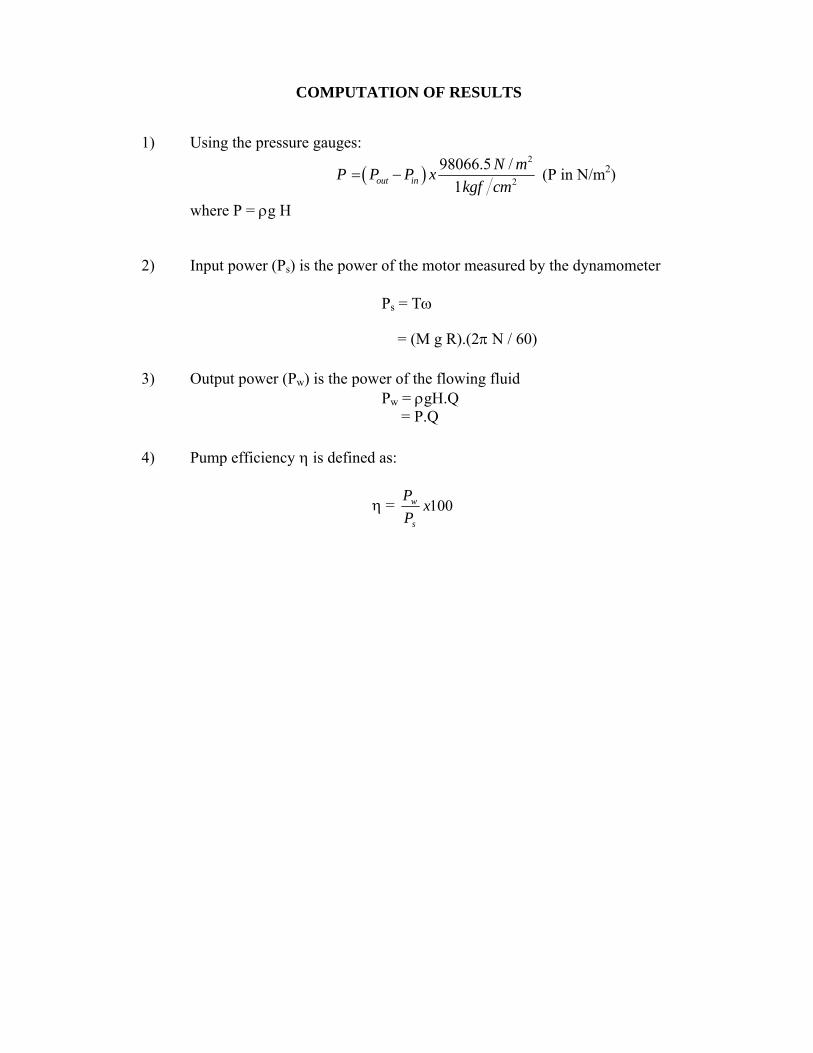
COMPUTATION OF RESULTS
1) Using the pressure gauges:
2
2
98066.5 /
1out in
N mP P P x
kgf cm (P in N/m2)
where P = g H 2) Input power (Ps) is the power of the motor measured by the dynamometer
Ps = T
= (M g R).(2 N / 60)
3) Output power (Pw) is the power of the flowing fluid Pw = gH.Q = P.Q 4) Pump efficiency is defined as:
= 100xP
P
s
w
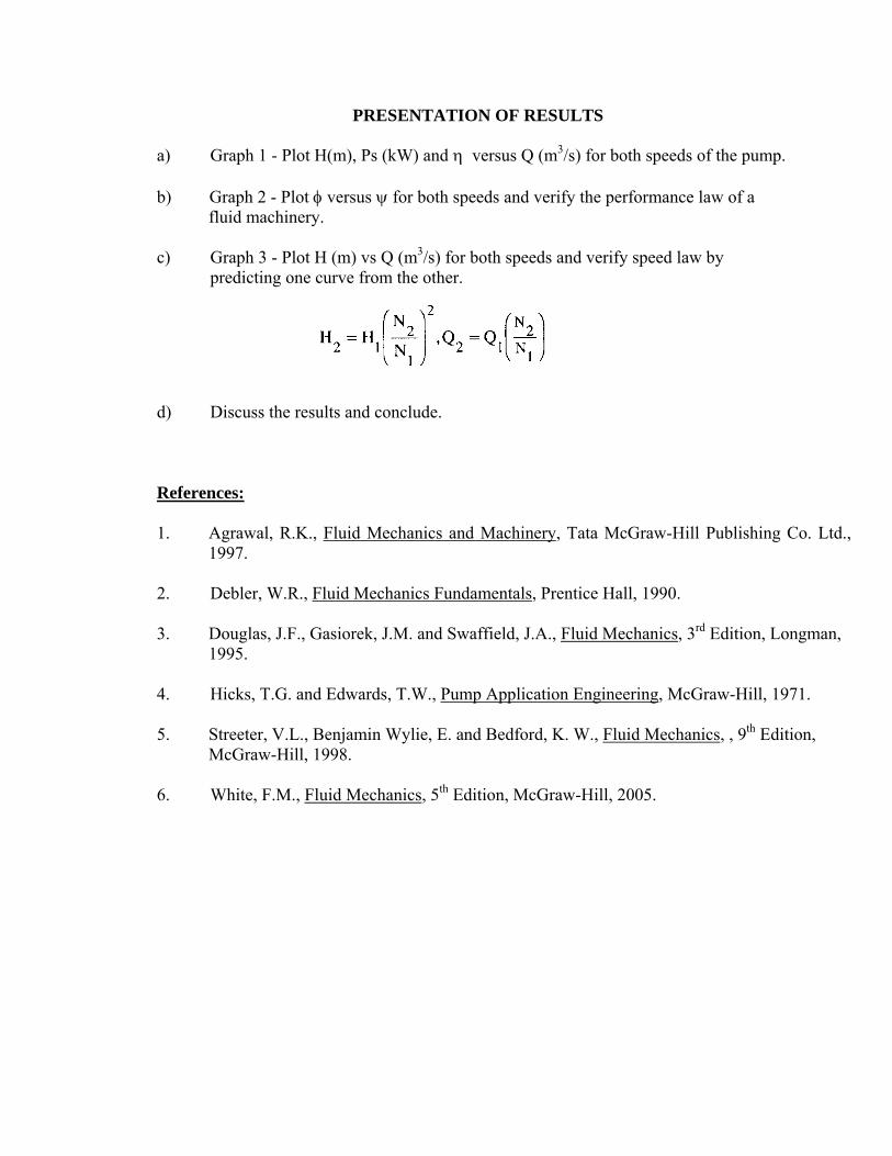
PRESENTATION OF RESULTS
a) Graph 1 - Plot H(m), Ps (kW) and versus Q (m3/s) for both speeds of the pump. b) Graph 2 - Plot versus for both speeds and verify the performance law of a fluid machinery. c) Graph 3 - Plot H (m) vs Q (m3/s) for both speeds and verify speed law by predicting one curve from the other.
d) Discuss the results and conclude.
References: 1. Agrawal, R.K., Fluid Mechanics and Machinery, Tata McGraw-Hill Publishing Co. Ltd., 1997. 2. Debler, W.R., Fluid Mechanics Fundamentals, Prentice Hall, 1990. 3. Douglas, J.F., Gasiorek, J.M. and Swaffield, J.A., Fluid Mechanics, 3rd Edition, Longman, 1995. 4. Hicks, T.G. and Edwards, T.W., Pump Application Engineering, McGraw-Hill, 1971. 5. Streeter, V.L., Benjamin Wylie, E. and Bedford, K. W., Fluid Mechanics, , 9th Edition, McGraw-Hill, 1998. 6. White, F.M., Fluid Mechanics, 5th Edition, McGraw-Hill, 2005.

Figure 1. HP 309 Series and Parallel Pumps Test Set

Flow meter
P5
P4 V4
P3 P2
P1
V5
V9 V2
V1
V7
V6
Pump 1
Pump 2
Measuring Tank
Over flow
Strainer
V8 Storage Tank
Figure 2. Isometric Piping System of the Test Unit for Parallel Pumps
V3

ME 2135-1 Centrifugal Pump Experiment - Work Sheet – Pump 1 Experiment Date: ____________
Workgroup: ____________
N1 = (rpm) = (rad/s)
(Note: Pump speed N should be maintained constant for different valve settings)
Valve Setting M (kg)
Suction Pressure, Pin (kgf/cm2)
Discharge Pressure, Pout
(kgf/cm2) Pressure Head
(kgf/cm2) Volume Flow Rate,
Q, m3/hr Input Shaft Power,
Ps, (KW) Output Power,
Pw, (KW) Efficiency, , (%)
Fully Open
Fully Close
N2 = (rpm) = (rad/s)
(Note: Pump speed N should be maintained constant for different valve settings)
Valve Setting M (kg)
Suction Pressure, Pin (kgf/cm2)
Discharge Pressure, Pout
(kgf/cm2) Pressure
Head (kgf/cm2) Volume Flow Rate,
Q, m3/hr Input Shaft Power,
Ps, (KW) Output Power,
Pw, (KW) Efficiency, , (%)
Fully Open
Fully Close
Input Power : Ps = MgRN (N in rad/s) Torque Arm Length, R =
Output Power : Pw = wgH.Q (H in m) Impeller Diameter, D =
Unit Conversion: 1 kgf/cm2 = 98066.5 N/m2(Pa)

ME 2135-1 Centrifugal Pump Experiment - Work Sheet – Pump 2 Experiment Date: ____________
Workgroup: ____________
N1 = (rpm) = (rad/s)
(Note: Pump speed N should be maintained constant for different valve settings)
Valve Setting M (kg)
Suction Pressure, Pin (kgf/cm2)
Discharge Pressure, Pout
(kgf/cm2) Pressure Head
(kgf/cm2) Volume Flow Rate,
Q, m3/hr Input Shaft Power,
Ps, (KW) Output Power,
Pw, (KW) Efficiency, , (%)
Fully Open
Fully Close
N2 = (rpm) = (rad/s)
(Note: Pump speed N should be maintained constant for different valve settings)
Valve Setting M (kg)
Suction Pressure, Pin (kgf/cm2)
Discharge Pressure, Pout
(kgf/cm2) Pressure
Head (kgf/cm2) Volume Flow Rate,
Q, m3/hr Input Shaft Power,
Ps, (KW) Output Power,
Pw, (KW) Efficiency, , (%)
Fully Open
Fully Close
Input Power : Ps = MgRN (N in rad/s) Torque Arm Length, R =
Output Power : Pw = wgH.Q (H in m) Impeller Diameter, D =
Unit Conversion: 1 kgf/cm2 = 98066.5 N/m2(Pa)
Top Related