


Languages
Pages
Legal

MaxBotix®
Inc. Copyright 2005 - 2014 MaxBotix Incorporated Patent 7,679,996
MB8450 USB-CarSonar-WR
MaxBotix Inc., products are engineered and assembled in the USA. Page 1 Email: [email protected] Web: www.maxbotix.com
PD13256f
MB8450 USB-CarSonar-WR 2
USB Ultrasonic Proximity Sensor
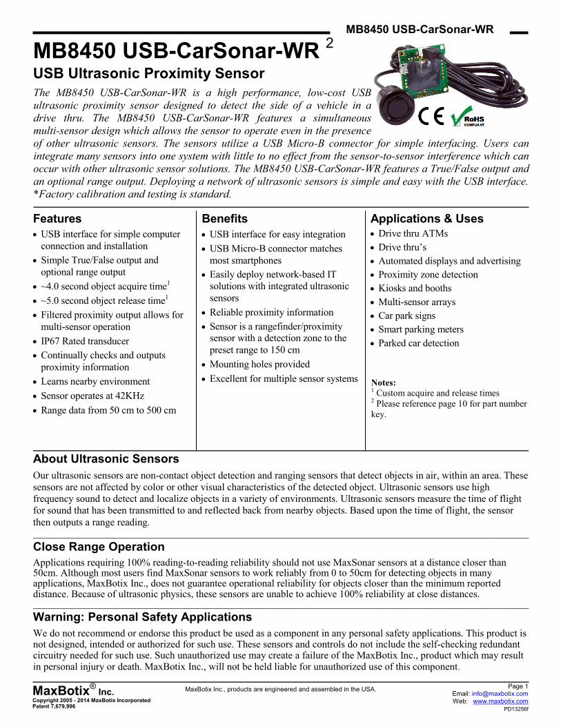
The MB8450 USB-CarSonar-WR is a high performance, low-cost USB
ultrasonic proximity sensor designed to detect the side of a vehicle in a
drive thru. The MB8450 USB-CarSonar-WR features a simultaneous
multi-sensor design which allows the sensor to operate even in the presence
of other ultrasonic sensors. The sensors utilize a USB Micro-B connector for simple interfacing. Users can
integrate many sensors into one system with little to no effect from the sensor-to-sensor interference which can
occur with other ultrasonic sensor solutions. The MB8450 USB-CarSonar-WR features a True/False output and
an optional range output. Deploying a network of ultrasonic sensors is simple and easy with the USB interface.
*Factory calibration and testing is standard.
Features
USB interface for simple computer
connection and installation
Simple True/False output and
optional range output
~4.0 second object acquire time1
~5.0 second object release time1
Filtered proximity output allows for
multi-sensor operation
IP67 Rated transducer
Continually checks and outputs
proximity information
Learns nearby environment
Sensor operates at 42KHz
Range data from 50 cm to 500 cm
Benefits
USB interface for easy integration
USB Micro-B connector matches
most smartphones
Easily deploy network-based IT
solutions with integrated ultrasonic
sensors
Reliable proximity information
Sensor is a rangefinder/proximity
sensor with a detection zone to the
preset range to 150 cm
Mounting holes provided
Excellent for multiple sensor systems
Applications & Uses
Drive thru ATMs
Drive thru’s
Automated displays and advertising
Proximity zone detection
Kiosks and booths
Multi-sensor arrays
Car park signs
Smart parking meters
Parked car detection
About Ultrasonic Sensors
Our ultrasonic sensors are non-contact object detection and ranging sensors that detect objects in air, within an area. These
sensors are not affected by color or other visual characteristics of the detected object. Ultrasonic sensors use high
frequency sound to detect and localize objects in a variety of environments. Ultrasonic sensors measure the time of flight
for sound that has been transmitted to and reflected back from nearby objects. Based upon the time of flight, the sensor
then outputs a range reading. _______________________________________________________________________________________________________________________________________
Close Range Operation
Applications requiring 100% reading-to-reading reliability should not use MaxSonar sensors at a distance closer than 50cm. Although most users find MaxSonar sensors to work reliably from 0 to 50cm for detecting objects in many applications, MaxBotix Inc., does not guarantee operational reliability for objects closer than the minimum reported distance. Because of ultrasonic physics, these sensors are unable to achieve 100% reliability at close distances. _______________________________________________________________________________________________________________________________________
Warning: Personal Safety Applications
We do not recommend or endorse this product be used as a component in any personal safety applications. This product is not designed, intended or authorized for such use. These sensors and controls do not include the self-checking redundant circuitry needed for such use. Such unauthorized use may create a failure of the MaxBotix Inc., product which may result in personal injury or death. MaxBotix Inc., will not be held liable for unauthorized use of this component.
Notes: 1 Custom acquire and release times 2 Please reference page 10 for part number
key.
MaxBotix®
Inc. Copyright 2005 - 2014 MaxBotix Incorporated Patent 7,679,996
MB8450 USB-CarSonar-WR
MaxBotix Inc., products are engineered and assembled in the USA. Page 2 Email: [email protected] Web: www.maxbotix.com
PD13256f
General Description of Operation
The sensors utilize a USB Micro-B connector for interfacing. Each sensor is small in size with holes on the PCB for easy
mounting. Each MB8450 USB-CarSonar-WR sends serial data to the user’s operating system (OS) which can then be read
from the registered COM port (or equivalent) using a terminal program or read directly from the OS by using the
appropriate software functions.
Each MB8450 USB-CarSonar-WR is powered by the USB connection and begins operating after the USB handshaking
has occurred. Range data and proximity information is sent continuously to the user’s OS and is available to be read at
any time.
Connection is handled automatically by device drivers that are available for most OSs (Windows XP and later, Linux
Kernel 2.6 and later, Mac OS X and later.) The steps taken to perform the configuration vary slightly by the target OS,
however, the general operation and the data sent by the sensor remains the same. _______________________________________________________________________________________________________________________________________
Serial Output Format
The sensor output is provided over the COM port (or equivalent) in an ASCII character format. If a target is detected at
30 centimeters the output appears as follows: “R050 P1<carriage return>”. 50cm is the minimum reported distance for the
MB8450. The output is an ASCII capital “R”, followed by three ASCII character digits representing the range in
centimeters up to a maximum of 500 centimeters. This is followed by an ASCII space and the ASCII character “P”,
followed by one ASCII digit “1 or 0” corresponding to the “True or False” proximity information, followed by a carriage
return. A proximity value of “1” signifies that a target is present in the detection zone. A proximity value of “0” signifies
that no target has been detected in the detection zone.
The MB8450 USB-CarSonar-WR has a set trigger distance of ~150 cm. Objects closer than this distance that fall within
the sensor detection zone will charge the proximity timer. ~4.0 seconds later the sensor will begin sending the appropriate
proximity information.
When the detected object then leaves the detection zone the sensor will “release” the target ~5.0 seconds later. Release
time can be influenced by other nearby sensors and may appear to be longer in applications with many nearby sensors.
The MB8450 USB-CarSonar-WR also doubles as an ultrasonic range finder. Range information is provided for reference
and may experience noise when a large number of sensors (5+ depending on sensor mounting) are running in the same
environment. The range reading will report the range to an object to the maximum range of the sensor of
500 cm. When no object is detected by the sensor, the sensor will report R500.
__________________________________________________________________________________________________
Using Multiple Sensors in a Single System
The MB8450 USB-CarSonar-WR is designed to function with other ultrasonic sensors operating in the same space at the
same time on the same frequency. Our industry leading firmware allows users to connect multiple sensors across a single
space without worrying about sensor interference (cross-talk). Each sensor is rated to work with a limited number of
sensors within a space. For users working with large open environments or environments where sensors point in different
directions, it is likely that the recommended number of sensors can be exceeded with little or no effect on user
performance. __________________________________________________________________________________________________
Sensor Calibration & Pairing
Each MB8450 USB-CarSonar-WR is shipped as a PCB and transducer pair. Each MB8450 USB-CarSonar-WR-PCB and
MB8450 USB-CarSonar-WR-Transducer has received a custom calibration that matches and pairs the PCB and
transducer performance. Installing a new or different transducer into a MB8450 USB-CarSonar-WR-PCB may result in
unreliable performance. While it is understood that the transducer must be unplugged from the PCB to allow for
installation, it is important for installation that the transducer and PCB remain as a pair for functional calibration.
WARNING - While it is understood that the transducer must be unplugged from the PCB to
allow for installation, it is important for installation that the transducer and PCB remain as a
pair for functional calibration.
The matching components of the MB8450 USB-CarSonar-WR are shipped together and are designed to be mounted in the
final location as a PCB and transducer pair.
MaxBotix®
Inc. Copyright 2005 - 2014 MaxBotix Incorporated Patent 7,679,996
MB8450 USB-CarSonar-WR
MaxBotix Inc., products are engineered and assembled in the USA. Page 3 Email: [email protected] Web: www.maxbotix.com
PD13256f
Terminal Configuration
Windows OS Configuration
The MB8450 USB-CarSonar-WR inside Windows OS is a plug and play device. When the MB8450 ultrasonic proximity sensor is connected to a computer running Windows XP or newer, Windows will typically install and configure the device drivers automatically. This configuration may take several minutes, but the device configuration will only occur once.
Computers running Windows XP and older have HyperTerminal included in the OS. Computers running Windows Vista and newer require the installation of software that is able to communicate with a communication port.
To configure the MB8450 USB-CarSonar-WR on computer systems running Windows, use the following directions:
If the provided software does not automatically find the first available MB8450 ultrasonic proximity sensor, use the following directions:
For multiple sensor operation, use the following instruction set:
Other Operating Systems
For users that need drivers, they may be available for your system at http://www.ftdichip.com/FTDrivers.htm
Value
Baud 57600
Data bits 8
Parity 0 / none
Stop Bit 1
Flow Control 0 / none
1. Download a terminal program. A simple terminal program is
available for download at www.maxbotix.com/terminal.htm
2. Unzip the terminal program to a folder of your choice, if using the
provided program.
3. Connect the MB8450 ultrasonic proximity sensor to a computer with a
Micro-B USB cable.
4. Allow Windows time to automatically configure MB8450 drivers.
5. Run the terminal program of preference. If using the provided
program, run the .exe file. The program provided should look for the
first available proximity sensor.
6. For users who operate with a different terminal program, set the
configuration to the settings provided.
Warning:
Removing the sensor
before Windows has
configured drivers
may result in drivers
being corrupted.
Please allow time for
Windows to fully
install and configure
drivers for the
MB8450 USB-
CarSonar-WR.
1. Click the “Settings” option.
2. In the “Serial port settings” window, change the “Port” option to the
COM port number assigned to the MB8450 ultrasonic proximity sensor.
1. Open a terminal window.
2. Click settings, if using the software provided for the MB8450 ultrasonic
proximity sensor.
3. Change the “Port” menu to match the newest “COM#”
4. Click “ok”.
MaxBotix®
Inc. Copyright 2005 - 2014 MaxBotix Incorporated Patent 7,679,996
MB8450 USB-CarSonar-WR
MaxBotix Inc., products are engineered and assembled in the USA. Page 4 Email: [email protected] Web: www.maxbotix.com
PD13256f
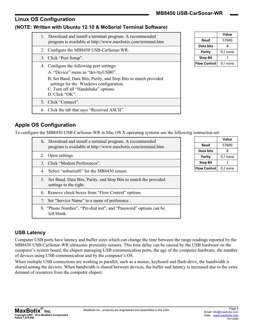
Linux OS Configuration
(NOTE: Written with Ubuntu 12.10 & MoSerial Terminal Software)
Apple OS Configuration
To configure the MB8450 USB-CarSonar-WR in Mac OS X operating systems use the following instruction set:
USB Latency
Computer USB ports have latency and buffer sizes which can change the time between the range readings reported by the
MB8450 USB-CarSonar-WR ultrasonic proximity sensors. This time delay can be caused by the USB hardware on the
computer’s system board, the chipset managing USB communication ports, the age of the computer hardware, the number
of devices using USB communication and by the computer’s OS.
When multiple USB connections are working in parallel, such as a mouse, keyboard and flash-drive, the bandwidth is
shared among the devices. When bandwidth is shared between devices, the buffer and latency is increased due to the extra
demand of resources from the computer chipset.
1. Download and install a terminal program. A recommended
program is available at http://www.maxbotix.com/terminal.htm
2. Configure the MB8450 USB-CarSonar-WR.
3. Click “Port Setup”.
4. Configure the following port settings:
A. “Device” menu as “dev/ttyUSB0”.
B. Set Baud, Data Bits, Parity, and Stop Bits to match provided
settings for the Windows configuration.
C. Turn off all “Handshake” options.
D. Click “OK”.
5. Click “Connect”.
6. Click the tab that says “Received ASCII”.
1. Download and install a terminal program. A recommended
program is available at http://www.maxbotix.com/terminal.htm
2. Open settings.
3. Click “Modem Preferences”.
4. Select “usbserial0” for the MB8450 sensor.
5. Set Baud, Data Bits, Parity, and Stop Bits to match the provided
settings to the right.
6. Remove check boxes from “Flow Control” options.
7. Set “Service Name” to a name of preference .
8. “Phone Number”, “Pre-dial init", and “Password” options can be
left blank.
Value
Baud 57600
Data bits 8
Parity 0 / none
Stop Bit 1
Flow Control 0 / none
Value
Baud 57600
Data bits 8
Parity 0 / none
Stop Bit 1
Flow Control 0 / none
MaxBotix®
Inc. Copyright 2005 - 2014 MaxBotix Incorporated Patent 7,679,996
MB8450 USB-CarSonar-WR
MaxBotix Inc., products are engineered and assembled in the USA. Page 5 Email: [email protected] Web: www.maxbotix.com
PD13256f
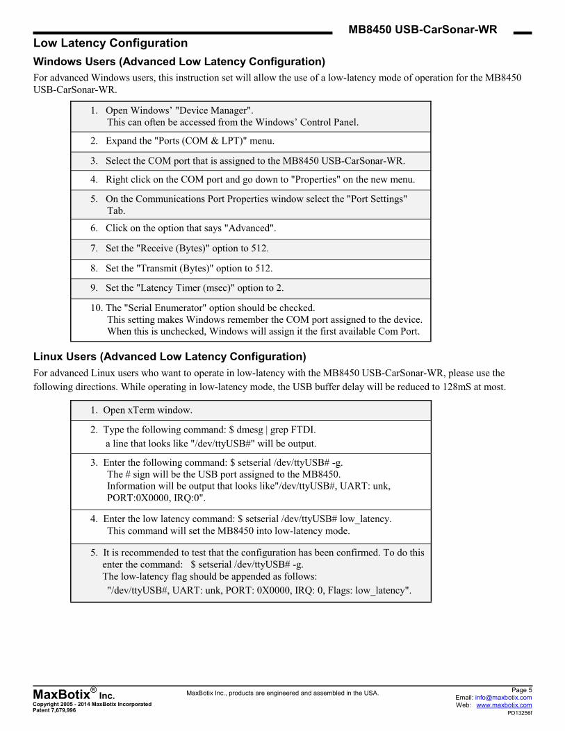
Low Latency Configuration
Windows Users (Advanced Low Latency Configuration)
For advanced Windows users, this instruction set will allow the use of a low-latency mode of operation for the MB8450
USB-CarSonar-WR.
Linux Users (Advanced Low Latency Configuration)
For advanced Linux users who want to operate in low-latency with the MB8450 USB-CarSonar-WR, please use the
following directions. While operating in low-latency mode, the USB buffer delay will be reduced to 128mS at most.
1. Open Windows’ "Device Manager".
This can often be accessed from the Windows’ Control Panel.
2. Expand the "Ports (COM & LPT)" menu.
3. Select the COM port that is assigned to the MB8450 USB-CarSonar-WR.
4. Right click on the COM port and go down to "Properties" on the new menu.
5. On the Communications Port Properties window select the "Port Settings"
Tab.
6. Click on the option that says "Advanced".
7. Set the "Receive (Bytes)" option to 512.
8. Set the "Transmit (Bytes)" option to 512.
9. Set the "Latency Timer (msec)" option to 2.
10. The "Serial Enumerator" option should be checked.
This setting makes Windows remember the COM port assigned to the device.
When this is unchecked, Windows will assign it the first available Com Port.
1. Open xTerm window.
2. Type the following command: $ dmesg | grep FTDI.
a line that looks like "/dev/ttyUSB#" will be output.
3. Enter the following command: $ setserial /dev/ttyUSB# -g.
The # sign will be the USB port assigned to the MB8450.
Information will be output that looks like"/dev/ttyUSB#, UART: unk,
PORT:0X0000, IRQ:0".
4. Enter the low latency command: $ setserial /dev/ttyUSB# low_latency.
This command will set the MB8450 into low-latency mode.
5. It is recommended to test that the configuration has been confirmed. To do this
enter the command: $ setserial /dev/ttyUSB# -g.
The low-latency flag should be appended as follows:
"/dev/ttyUSB#, UART: unk, PORT: 0X0000, IRQ: 0, Flags: low_latency".
MaxBotix®
Inc. Copyright 2005 - 2014 MaxBotix Incorporated Patent 7,679,996
MB8450 USB-CarSonar-WR
MaxBotix Inc., products are engineered and assembled in the USA. Page 6 Email: [email protected] Web: www.maxbotix.com
PD13256f
46 cm
_______________________________________________________________________________________________________________________________________
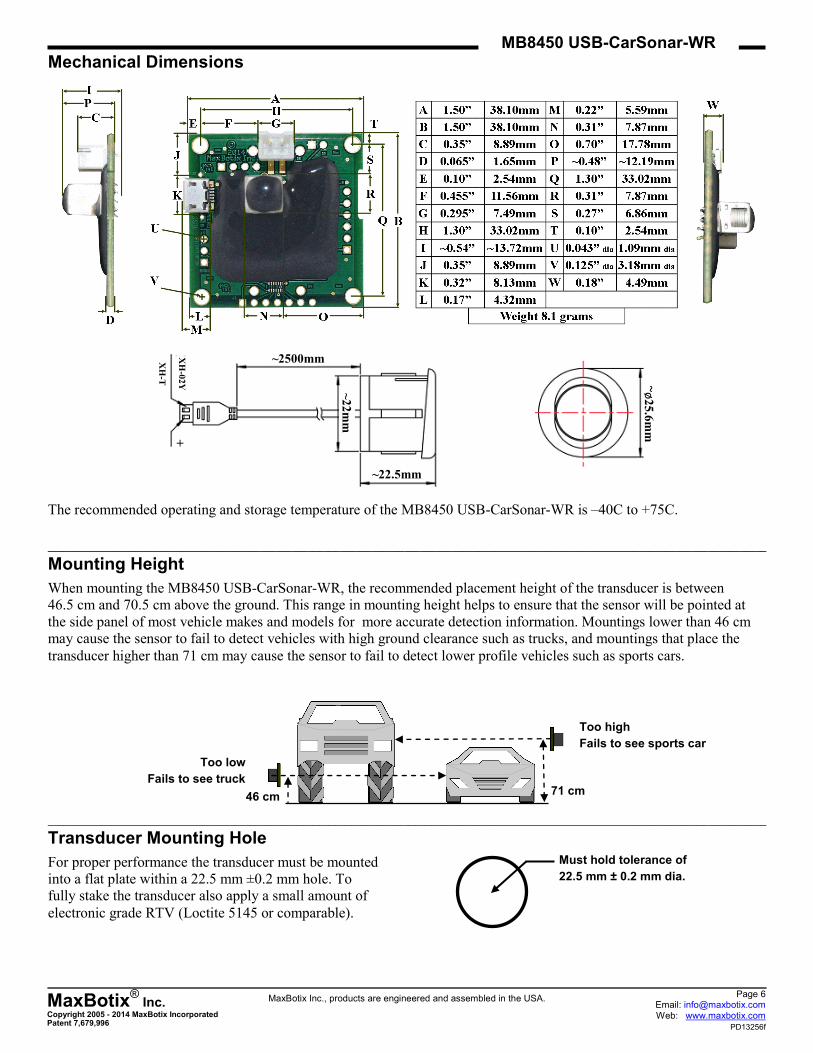
Mounting Height
When mounting the MB8450 USB-CarSonar-WR, the recommended placement height of the transducer is between
46.5 cm and 70.5 cm above the ground. This range in mounting height helps to ensure that the sensor will be pointed at
the side panel of most vehicle makes and models for more accurate detection information. Mountings lower than 46 cm
may cause the sensor to fail to detect vehicles with high ground clearance such as trucks, and mountings that place the
transducer higher than 71 cm may cause the sensor to fail to detect lower profile vehicles such as sports cars.
_______________________________________________________________________________________________________________________________________
Transducer Mounting Hole
For proper performance the transducer must be mounted
into a flat plate within a 22.5 mm ±0.2 mm hole. To
fully stake the transducer also apply a small amount of
electronic grade RTV (Loctite 5145 or comparable).
71 cm
Too low
Fails to see truck
Too high
Fails to see sports car
Must hold tolerance of
22.5 mm ± 0.2 mm dia.
~2500mm
~22.5mm ~
22
mm
+
XH
-02
Y
XH
-T ~ø
25
.6m
m
Mechanical Dimensions
The recommended operating and storage temperature of the MB8450 USB-CarSonar-WR is –40C to +75C.
MaxBotix®
Inc. Copyright 2005 - 2014 MaxBotix Incorporated Patent 7,679,996
MB8450 USB-CarSonar-WR
MaxBotix Inc., products are engineered and assembled in the USA. Page 7 Email: [email protected] Web: www.maxbotix.com
PD13256f
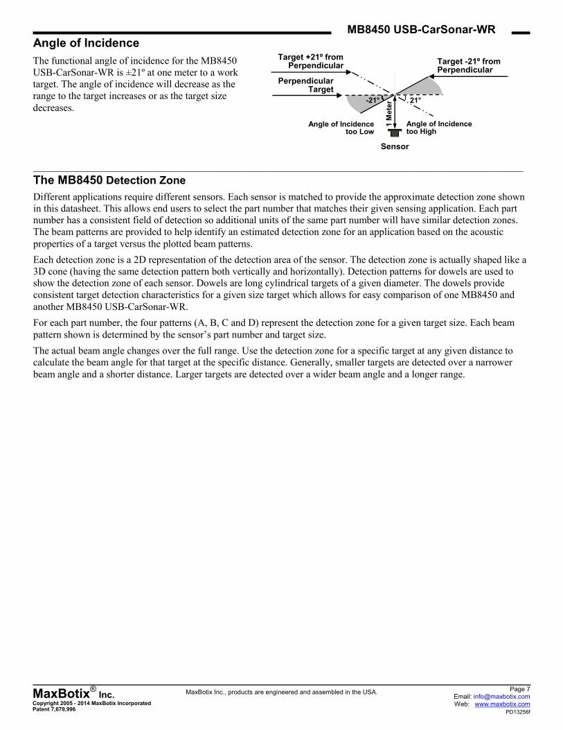
Angle of Incidence
_____________________________________________________________________________________________________________________________________
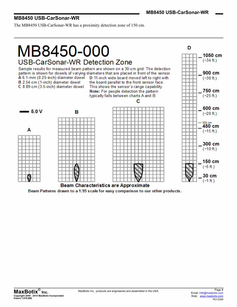
The MB8450 Detection Zone
Different applications require different sensors. Each sensor is matched to provide the approximate detection zone shown
in this datasheet. This allows end users to select the part number that matches their given sensing application. Each part
number has a consistent field of detection so additional units of the same part number will have similar detection zones.
The beam patterns are provided to help identify an estimated detection zone for an application based on the acoustic
properties of a target versus the plotted beam patterns.
Each detection zone is a 2D representation of the detection area of the sensor. The detection zone is actually shaped like a
3D cone (having the same detection pattern both vertically and horizontally). Detection patterns for dowels are used to
show the detection zone of each sensor. Dowels are long cylindrical targets of a given diameter. The dowels provide
consistent target detection characteristics for a given size target which allows for easy comparison of one MB8450 and
another MB8450 USB-CarSonar-WR.
For each part number, the four patterns (A, B, C and D) represent the detection zone for a given target size. Each beam
pattern shown is determined by the sensor’s part number and target size.
The actual beam angle changes over the full range. Use the detection zone for a specific target at any given distance to
calculate the beam angle for that target at the specific distance. Generally, smaller targets are detected over a narrower
beam angle and a shorter distance. Larger targets are detected over a wider beam angle and a longer range.
Target +21º from Perpendicular
Perpendicular Target
Target -21º from Perpendicular
1 M
ete
r
Angle of Incidence too Low
Angle of Incidence too High
-21° 21°
Sensor
The functional angle of incidence for the MB8450
USB-CarSonar-WR is ±21º at one meter to a work
target. The angle of incidence will decrease as the
range to the target increases or as the target size
decreases.
MaxBotix®
Inc. Copyright 2005 - 2014 MaxBotix Incorporated Patent 7,679,996
MB8450 USB-CarSonar-WR
MaxBotix Inc., products are engineered and assembled in the USA. Page 8 Email: [email protected] Web: www.maxbotix.com
PD13256f
MB8450 USB-CarSonar-WR
The MB8450 USB-CarSonar-WR has a proximity detection zone of 150 cm.
MaxBotix®
Inc. Copyright 2005 - 2014 MaxBotix Incorporated Patent 7,679,996
MB8450 USB-CarSonar-WR
MaxBotix Inc., products are engineered and assembled in the USA. Page 9 Email: [email protected] Web: www.maxbotix.com
PD13256f
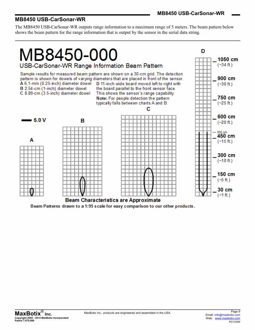
MB8450 USB-CarSonar-WR
The MB8450 USB-CarSonar-WR outputs range information to a maximum range of 5 meters. The beam pattern below
shows the beam pattern for the range information that is output by the sensor in the serial data string.
MaxBotix®
Inc. Copyright 2005 - 2014 MaxBotix Incorporated Patent 7,679,996
MB8450 USB-CarSonar-WR
MaxBotix Inc., products are engineered and assembled in the USA. Page 10 Email: [email protected] Web: www.maxbotix.com
PD13256f
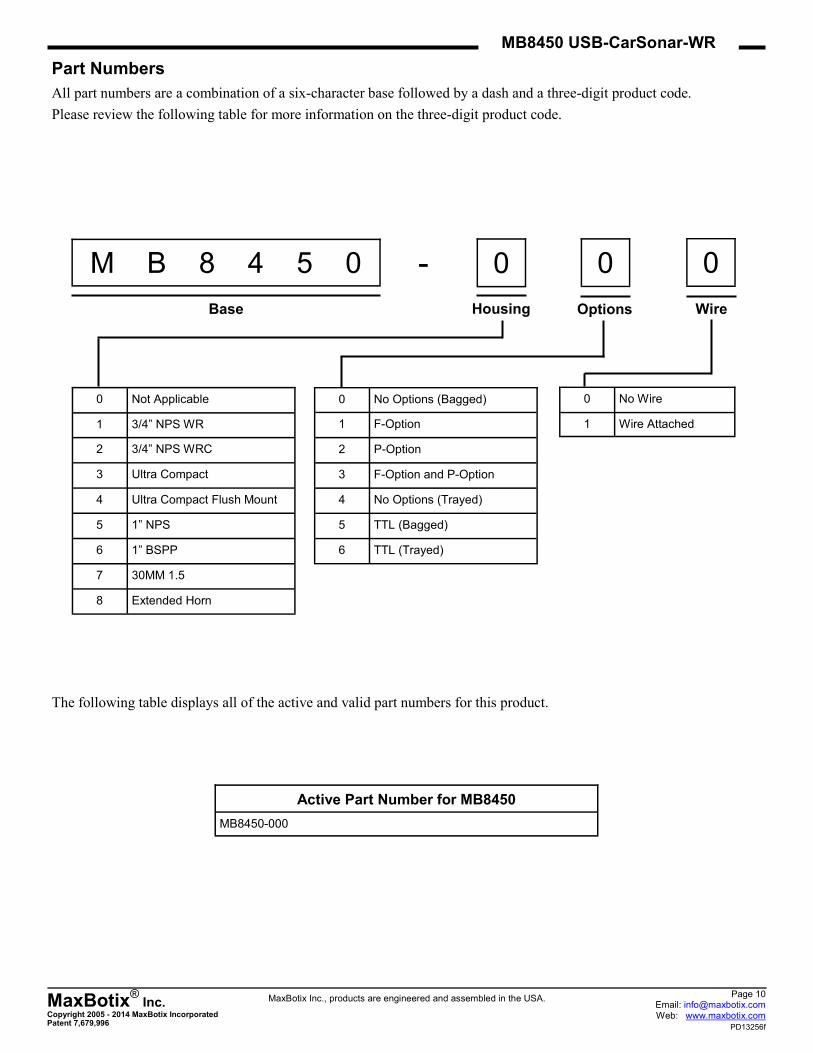
0 Not Applicable
1 3/4” NPS WR
2 3/4” NPS WRC
3 Ultra Compact
4 Ultra Compact Flush Mount
5 1” NPS
6 1” BSPP
7 30MM 1.5
8 Extended Horn
0 No Options (Bagged)
1 F-Option
2 P-Option
3 F-Option and P-Option
4 No Options (Trayed)
5 TTL (Bagged)
6 TTL (Trayed)
0 No Wire
1 Wire Attached
Options Wire
0 0 0 - M B 8 4 5 0
Base Housing
Part Numbers
All part numbers are a combination of a six-character base followed by a dash and a three-digit product code.
Please review the following table for more information on the three-digit product code.
The following table displays all of the active and valid part numbers for this product.
Active Part Number for MB8450
MB8450-000
MaxBotix®
Inc. Copyright 2005 - 2014 MaxBotix Incorporated Patent 7,679,996
MB8450 USB-CarSonar-WR
MaxBotix Inc., products are engineered and assembled in the USA. Page 11 Email: [email protected] Web: www.maxbotix.com
PD13256f
After reviewing this datasheet, do you have any more questions?
We offer Technical Support on all of our products even if you purchased them through one of our many vendors
worldwide.
You can fill out a Technical Support form for assistance on a sensor here --> Technical Support
Not sure which sensor you need for your application?
We offer Sensor Selection Assistance, click the link here to fill out a form for support --> Sensor Selection Help
Looking for tutorials to help you get started?
Frequently Asked Questions about Our Sensors
We receive many questions about our products and services. This resource offers answers to common inquiries
we receive about our product lines and their application.
Fully Calibrated Beam Patterns
All of our sensors are factory calibrated to provide consistent beam patterns, detection zones, to fit into a wide
variety of applications. In our product lines, each model number comes with a different beam pattern that reflects
the sensitivity and the detection zone of how it sees a target. Additionally, we strive to maintain consistency be-
tween our finished products, and you will see little to no deviation between sensors of the same model. This al-
lows you to have confidence in your final application when using multiple sensors.
Understanding Range Readings
The success of an application may hinge upon knowing the exact location of a target. However, a sensor may
report one meter even if the target is not exactly one meter away from the sensor. Sensor specifications, such as
resolution, precision, and accuracy, help you to understand sensor performance.
How to Use Multiple Ultrasonic Sensors
This guide covers three ways to run your sensors in a Multiple Sensor environment and issues you may face.
Contact us now with any questions at [email protected] or call +1-218-454-0766.
Please call during our preferred business hours of 8:00 am – 4:30 pm EST on Monday through Thursday and 8:00 am –
2:00 pm EST on Friday, or you may leave us a voicemail anytime.
Top Related