


Languages
Pages
Legal


8/9/2019 Manual Fe Power Tools FEB 30 FEB 45
http://slidepdf.com/reader/full/manual-fe-power-tools-feb-30-feb-45 1/7

8/9/2019 Manual Fe Power Tools FEB 30 FEB 45
http://slidepdf.com/reader/full/manual-fe-power-tools-feb-30-feb-45 2/7
Operating Manual Fe Powertools Deburring and Chamfering
Machine FEB 30 and FEB 45List of contents:
1. Specification
2. Application
3. Tool change
4. Maintenance5. Component drawing
Carefully read this before putting the machine
into operation
EC Attestation of conformity according to the machine
recommendations 98/37 EG.
This product corresponds to the basic requirements of the
relevant EC recommendations.An assessment procedure regarding conformity has been carried
out according to the recommendations.
EC recommendations: 98/37/EG
89/336/EWG
737237EWG
Harmonized standards: EN 61 000 – EN 55 014 –
EN 50 144
Fe Powertools provides the following technical documentation for
examination:
Operating ManualConstruction plans
Test documents

8/9/2019 Manual Fe Power Tools FEB 30 FEB 45
http://slidepdf.com/reader/full/manual-fe-power-tools-feb-30-feb-45 3/7
1) Specification:
Motor voltage: 220-240 V AC
Output: 1500 Watt
Speed: 6000 min-1
Overheating protection: X
Overload control X
Soft start X
Feed: manual
Chamfer angle: 45° optional 30°
Land width: 45° 0 - 8 mm continuously
30° 0 -7 mm continuously
Size: 330 x 138 x 295 mm
Weight: 4.6 Kg
Scope of delivery:
1 Deburring and chamfering machine1 Milling tool 45° optional 30° (depend. on the order No.)
2 Sintered carbide reversible disks SHM 200
1 Spanner SW 22
1 Sickle spanner
1 Torx screw driver T9
1 Carry case
1 Operating manual
2) Application: The Fe Powertools beveling machine is ideally suitable for the deburring and
chamfering of metal parts made of steel, stainless steel,
nonferrous metals, brass and plastics.
The handy, compact design allows the use for straight
edges, internal and external radii and bore holes from ø 22
mm. The fine adjustment allows slight chamfers for deburring
up to the preparation of welding seams.
Two milling cutters with a chamfering angle of 45° or
optionally 30° are available. The reversible disks can be
used in 3 ways. Due to the small guiding roller, insertion intobore holes from ø 22 mm is possible without any problems.
The machine is suitable for the following fields of
application:
Mould making:
Deburring of contours, radii, bore holes
Boiler and process plant construction: Preparation of
welding seams on heat exchangers
(bores) Preparation of welding seams 30° up to 7 mm
Mechanical engineering: Deburring of machine parts.Chamfering of edges as protection against peeling of

8/9/2019 Manual Fe Power Tools FEB 30 FEB 45
http://slidepdf.com/reader/full/manual-fe-power-tools-feb-30-feb-45 4/7
the varnish after painting.
Making of visible edges.
Sheet metal working: Deburring of cutting edges.
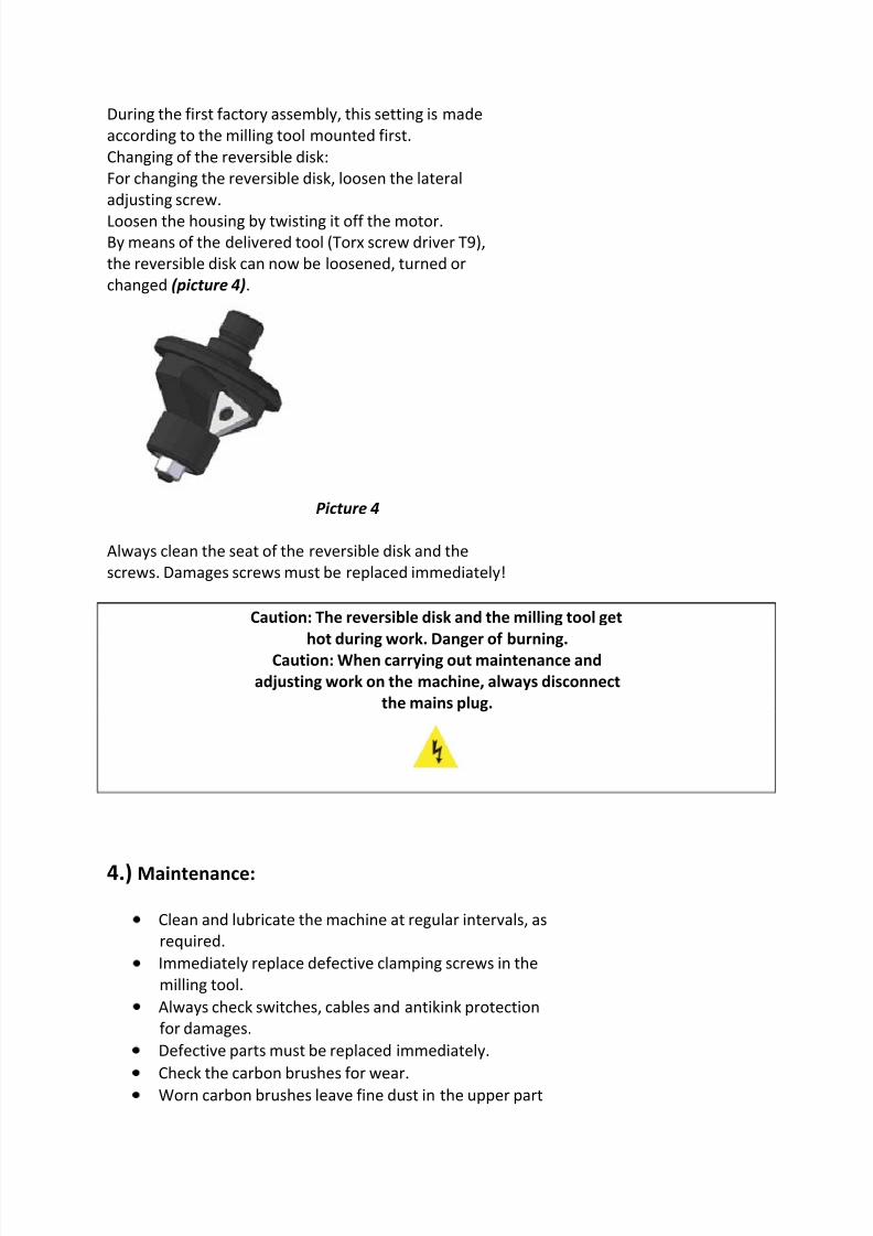
Setting of the land height:
For setting the land height loosen the lateral clamping
lever (picture 1) and set the desired dimension
by rotating the complete machine head.
The set value can be read from the graduated collar
(picture 2).
Picture 1
Picture 2
Switching-on and positioning of the machine:
Caution: Always wear eye protectors!
Grip both handles and place the machine
exactly straight with the supporting plate onto the material.
Switch the motor on and wait until the maximum
speed is reached.
This will take about 3 seconds.
Now slowly and evenly immerge the milling tool into thematerial.

8/9/2019 Manual Fe Power Tools FEB 30 FEB 45
http://slidepdf.com/reader/full/manual-fe-power-tools-feb-30-feb-45 5/7
Always work exactly opposite the rotating direction of the
tool.
Pay attention to the marks for the direction of rotation on
the supporting plate.
Work with a steady feed and try to obtain a neatly milled
surface.
Always take care that the machine is properly positioned
with the supporting plate.
Switching the machine off:
First remove the machine from the material.
Only switch the machine off when the milling tool is not
working anymore in the material.
Caution: Never touch the rotating milling tool!
3.) Tool change:For changing the milling tool, loosen the lateral adjusting
screw.
Loosen the housing by twisting it off the motor.
Now, the milling tool can be removed by means of the
tools, which are part of the delivery (spanner SW 22 ,
sickle spanner) (picture 3).
Picture 3
Now, screw the desired milling tool in.
Attach the housing onto the motor again.
Tighten the adjusting screw.
Caution: When carrying out maintenance and
adjusting work on the machine, always
disconnect the mains plug.
8/9/2019 Manual Fe Power Tools FEB 30 FEB 45
http://slidepdf.com/reader/full/manual-fe-power-tools-feb-30-feb-45 6/7

8/9/2019 Manual Fe Power Tools FEB 30 FEB 45
http://slidepdf.com/reader/full/manual-fe-power-tools-feb-30-feb-45 7/7
of the motor. Therefore, clean the upper part of the motor
at regular intervals. When doing so, also remove the chip
particles, which possibly entered the motor through the
ventilation openings.
Repairs may only be carried out by specializedpersonnel and by approved workshops.
Warranty
The warranty period for FE Powertools Electric Tools is 12 months as of
the date of purchase.Damages due to wear and tear, overload or improper handling
of the machine are excluded from the warranty. Damages that
are due to fault in material or defect of fabrication will be
remedied free of costs by compensation delivery or repair.
Complaints can only be accepted if the device is sent
undismantled and free to Fe Powertools or to a competent service
partner.
Claims for damages cannot be derived from this warranty.
Please fill out the warranty or add the purchase receipt.
----------------------------------------------------------------------------
----------------------------------------------------------------------------
Machine type
Machine number
Date of purchase
Stamp/signature specialized dealers
----------------------------------------------------------------------------
Error description
Top Related