


Languages
Pages
Legal

Please route to the individual responsible for trailer maintenanceP
art
No
. 421
0140
1
maintenance manualfor van and platform trailers
maintenance manual
dr ive away with more
VANSReporting Safety Defects . . . . . . . . . . . . . . . . . . . . 2Reporting Other Claims. . . . . . . . . . . . . . . . . . . . . . 2Introduction . . . . . . . . . . . . . . . . . . . . . . . . . . . . . . . 3Maintenance Tips . . . . . . . . . . . . . . . . . . . . . . . . . . 4Appearance Maintenance . . . . . . . . . . . . . . . . . . . . 5Freezing Weather Maintenance. . . . . . . . . . . . . . . . 5Suggested Preventive Maintenance . . . . . . . . . . . . 5Electrical System. . . . . . . . . . . . . . . . . . . . . . . . . . . 6Brake Maintenance . . . . . . . . . . . . . . . . . . . . . . . . . 7Brake Care and Adjustment . . . . . . . . . . . . . . . . . . 8Brake Adjusters . . . . . . . . . . . . . . . . . . . . . . . . . . . . 9Parking Brakes . . . . . . . . . . . . . . . . . . . . . . . . . . . 10Brake Balance . . . . . . . . . . . . . . . . . . . . . . . . . . . . 10Oil Seals and Hub Caps . . . . . . . . . . . . . . . . . . . . 11Wheel Bearings . . . . . . . . . . . . . . . . . . . . . . . . . . . 11Suspensions . . . . . . . . . . . . . . . . . . . . . . . . . . . . . 13Running Gear Assembly . . . . . . . . . . . . . . . . . . . . 14Servicing Rims and Wheels. . . . . . . . . . . . . . . . . . 14Single-Piece Rim Wheels . . . . . . . . . . . . . . . . . . . 15Rim and Wheel Inspection and Maintenance . . . . 15Rim and Wheel Problems . . . . . . . . . . . . . . . . . . . 16Tire Care . . . . . . . . . . . . . . . . . . . . . . . . . . . . . . . . 17Axle Alignment. . . . . . . . . . . . . . . . . . . . . . . . . . . . 19Upper Coupler and Kingpin . . . . . . . . . . . . . . . . . 20Pintle Hook . . . . . . . . . . . . . . . . . . . . . . . . . . . . . . 21Support Gear. . . . . . . . . . . . . . . . . . . . . . . . . . . . . 21Rear Impact Guard . . . . . . . . . . . . . . . . . . . . . . . . 21Side and Roof Panels - Vans . . . . . . . . . . . . . . . . 22Rear Frame, Doors and Hardware . . . . . . . . . . . . 22Entry and Exit . . . . . . . . . . . . . . . . . . . . . . . . . . . . 23Floor System . . . . . . . . . . . . . . . . . . . . . . . . . . . . . 23Insulated Trailer Maintenance . . . . . . . . . . . . . . . . 23Maintaining Insulation Efficiency . . . . . . . . . . . . . . 24Safety Measures - Urethane Foam . . . . . . . . . . . . 24Converter Dolly . . . . . . . . . . . . . . . . . . . . . . . . . . . 25Alterations to the Trailer . . . . . . . . . . . . . . . . . . . . 26
PLATFORMSReporting Safety Defects . . . . . . . . . . . . . . . . . . . . 2Reporting Other Claims. . . . . . . . . . . . . . . . . . . . . . 2Introduction . . . . . . . . . . . . . . . . . . . . . . . . . . . . . . . 3Maintenance Tips . . . . . . . . . . . . . . . . . . . . . . . . . . 4Appearance Maintenance . . . . . . . . . . . . . . . . . . . . 5Freezing Weather Maintenance. . . . . . . . . . . . . . . . 5Suggested Preventive Maintenance . . . . . . . . . . . . 5Electrical System. . . . . . . . . . . . . . . . . . . . . . . . . . . 6Brake Maintenance . . . . . . . . . . . . . . . . . . . . . . . . . 7Brake Care and Adjustment . . . . . . . . . . . . . . . . . . 8Brake Adjusters . . . . . . . . . . . . . . . . . . . . . . . . . . . . 9Parking Brakes . . . . . . . . . . . . . . . . . . . . . . . . . . . 10Brake Balance . . . . . . . . . . . . . . . . . . . . . . . . . . . . 10Oil Seals and Hub Caps . . . . . . . . . . . . . . . . . . . . 11Wheel Bearings . . . . . . . . . . . . . . . . . . . . . . . . . . . 11Suspensions . . . . . . . . . . . . . . . . . . . . . . . . . . . . . 13Running Gear Assembly . . . . . . . . . . . . . . . . . . . . 14Servicing Rims and Wheels. . . . . . . . . . . . . . . . . . 14Single-Piece Rim Wheels . . . . . . . . . . . . . . . . . . . 15Rim and Wheel Inspection and Maintenance . . . . 15Rim and Wheel Problems . . . . . . . . . . . . . . . . . . . 16Tire Care . . . . . . . . . . . . . . . . . . . . . . . . . . . . . . . . 17Axle Alignment. . . . . . . . . . . . . . . . . . . . . . . . . . . . 19Upper Coupler and Kingpin . . . . . . . . . . . . . . . . . 20Pintle Hook . . . . . . . . . . . . . . . . . . . . . . . . . . . . . . 21Support Gear. . . . . . . . . . . . . . . . . . . . . . . . . . . . . 21Rear Impact Guard . . . . . . . . . . . . . . . . . . . . . . . . 21Floor System . . . . . . . . . . . . . . . . . . . . . . . . . . . . . 23Main Beams. . . . . . . . . . . . . . . . . . . . . . . . . . . . . . 25Crossmembers . . . . . . . . . . . . . . . . . . . . . . . . . . . 25Extendable Platforms . . . . . . . . . . . . . . . . . . . . . . 25Converter Dolly . . . . . . . . . . . . . . . . . . . . . . . . . . . 25Running Gear Assembly . . . . . . . . . . . . . . . . . . . . 26Alterations to the Trailer . . . . . . . . . . . . . . . . . . . . 26
Bibliography. . . . . . . . . . . . . . . . . . . . . . . . . . . . . . . . . . . . . . . . . . . . . . . . . . . . . . . . . . . . . . . . . . . . . . . . . . . . . . . 27Appendix . . . . . . . . . . . . . . . . . . . . . . . . . . . . . . . . . . . . . . . . . . . . . . . . . . . . . . . . . . . . . . . . . . . . . . . . . . . . . . . . . 28
maintenance manual
This vehicle was designed and quality inspected to conform with all applicable National Highway TrafficSafety Administration (NHTSA) safety standards. Great Dane LLC warrants this vehicle to be free fromdefects in materials and workmanship in accordancewith its standard printed warranty (see Appendix). If you detect a defect that could cause an accident,injury or death; or if you wish to report any such accident, injury or death, or any property damage claim or other complaint not addressed to the Customer Service Department, then you should in writing advise:
Director, Customer Service Great Dane LLC
P.O. Box 67Savannah, GA 31402-0067
If you believe that your vehicle has a defect which couldcause a crash or could cause injury or death, youshould immediately inform NHTSA in addition to notifying Great Dane LLC.
If NHTSA receives similar complaints, it may open aninvestigation, and if it finds that a safety defect exists ina group of vehicles, it may order a recall and remedycampaign. However, NHTSA cannot become involved inindividual problems between you, your dealer, or GreatDane LLC.
To contact NHTSA, you may call the Vehicle SafetyHotline toll-free at 1-888-327-4236 (TTY: 1-800-424-9153); go to http://www.safercar.gov; or write to:
Administrator, NHTSA, 1200 New Jersey Avenue, SE West BuildingWashington, DC 20590.
You can also obtain other information about motor vehicle safety from http://www.safercar.gov.
Customer Service Phone Number: 877-369-3493
The Great Dane Operator’s Manual, included withevery new trailer, will give specific information about the following subjects:
Gross Axle Weight Rating (GAWR)
Gross Vehicle Weight Rating (GVWR)
Cargo Capacity
Proper Loading & Weight Distribution
Information shown in this Maintenance Manual is general information for maintenance and preventivemaintenance of your Great Dane trailer. It is strongly recommended that you obtain specific maintenanceinstructions provided by the manufacturers of the components specified on this trailer. Refer to the bibliography in the back of this manual.
It is recommended that all necessary replacement components be from the original equipmentmanufacturers to insure proper fit and to maintain the structural capability built into your vehicle.
2 3
reporting safety defects and other claims
warningThis safety alert symbol is used throughout this manual to indicate potentialpersonal safety hazards. Failure to heed the warnings associated with thesafety alert symbol can result in property damage, serious injury or death.
safety precautionsBefore performing any maintenance or repairwork which requires raising the vehicle, ensurevehicle is properly supported with lift stands ofsufficient rating capacity. Do not rely on jacksalone for support of the vehicle.
Safety glasses and hard hats should be wornwhen repairing and maintaining this vehicle.
A serious or fatal injury can occur...A. If you lack proper training.B. If you fail to follow proper safe procedures.C. If you do not use proper tools and
safety equipment.D. If you fail to use compatible replacement
components.
notice
This manual has been prepared to assist you in retain-ing the safety, dependability, and performance that arebuilt into Great Dane trailers. It is essential that this trail-er receives periodic inspections, maintenance, andservice parts replacement.
Maintenance should be performed by Great Danebranches and dealers, or other qualified service outletsthat regularly provide such service. The Great DaneOperator’s Manual covers pre-trip inspections, safetyand maintenance checks, and other helpful informationregarding Great Dane trailers. If you have questionsabout this manual or its instructions, contact GreatDane Trailers Customer Service Department foranswers.
It is important that every trailer owner and/or operatorhave an organized Trailer Preventive Maintenance (TPM)program. The United States Department of Transportationrequires that the maintenance records be kept on everycommercial highway vehicle.
It is to your advantage to be able to show that regularlyscheduled TPM inspection checks have been made onevery piece of equipment operated. A regular TPM program will assure that you get the most from yourGreat Dane trailer.
introduction
BREAKING-IN A NEW TRAILERThe most critical time in a new trailer’s life is its initialin-service check and first month’s “shakedown.”Preventive maintenance mechanics should be alert forunder-inflated tires and threaded fasteners that mayhave loosened from factory-torque settings. Fastenertorque should be all-inclusive and include refrigerationunits, tanks, steps, carriers etc.
Following are several areas that deserve particularlyclose attention during the first 30 days of a van or platform trailer’s service life. Of course, your operation’s maintenance records should reflect all areaswhich need to be closely checked.
TIRESWhile a new trailer’s tires were correctly inflated whenthey were mounted at the factory, tire pressure is related to ambient temperature at inflation time. If a newtrailer had tires mounted in a 70˚ F. ambient environment, but was put in service in 20˚ F. weather,the tires may have lost as much as 10 psi for every dropof 20˚ F. in ambient temperatures below 50˚ F. Therefore,all tire pressures should be verified with an air gauge,and rechecked each time the tractor refuels.
WHEELSSmaller fleets commonly overlook the need to retightennew-trailer-wheel lug nuts after the first 50 to 100 mi. ofservice on the initial “in-service.” Retightening compensates for “normal” clamp force lost due to“seating in” of new materials. Tests have shown new-trailer-wheel lug nuts lose 250 lb-ft, or about half oftheir original torque value, during a short period of initialservice. Unless those nuts are retightened to spec,additional clamping force will be lost, and damage to components will occur. Re-tightening duringthe initial in-service prevents wheel and stud damage.Thereafter, lug nuts should be checked every 25,000 mi.
LEAF-SPRING SUSPENSIONSAll tandem axles are aligned when new trailers leave thefactory. However, suspension fasteners may sometimesloosen, possibly causing alignment settings to change,and that can translate into possible erratic ride, oraccelerated tire wear. Therefore, at the first TPM interval, all suspension-system fasteners should berechecked for correct torque value.
When tightening suspension-system fasteners, mechanics must tighten the “nut side” of torque-armbolts. Tightening bolt heads does not produce the correct clamping force on the fastener.
It is also important to keep U-bolts, as well as torque-arm bolts, tight. Loose U-bolts allow trailer axles toshift, and even minor shifting during braking can causecontrol problems, excessive tire wear, or even brokenspring leaves.
When U-bolts are torqued to proper specs, leaf-springmain leaves remain in proper contact with wear pads,with no “twists.” Spring wear-pad contact will then beeven, too.
Also, at the first TPM, a trailer mechanic should take thetime to verify that there are no obstructions to move-ment of the suspension equalizers.
When the mechanic has made sure all fasteners aretight, he should use the 50-ft.-tape method, with axleextenders, to verify that the trailer tandem is, indeed,properly aligned. Remember: the longer the trailer, the more critical tandem alignment is to long tire life.
AIR-SPRING SUSPENSIONSLoose U-bolts in an air-spring suspension can cause anew trailer to roll and sway. Usually, a driver is quick to report this condition. The mechanic should makedoubly sure that trailer-suspension fasteners, includingU-bolts, are properly tightened.
Excessive play in an air-spring suspension’s front-pivotconnection is another cause of premature tire wear anderratic handing. Again, connection bolts, which mayhave loosened during the first weeks of service, mayproduce such handling problems. If not retightened,these loose bolts can cause rubber bushing wear.
SLIDING-TANDEM OPERATIONA driver learning to handle a new trailer equipped with asliding tandem should be sure he knows exactly how touse the stop-selector bar. He should also make surethat all four slider lock pins are set in place before operating the trailer, otherwise the tandem may not be“locked,” and a sudden brake application could forcethe slider rearward, causing damage to the tandem and trailer.
AIR SYSTEM AND BRAKE OPERATIONDuring the first month’s operation, a certain amount of “burnishing in” of brake lining occurs. This is normaland may result in some adjustment loss. Because out-of-adjustment trailer brakes mean increased stop-ping distance, plus an increased potential for jackknif-ing under certain conditions, trailer brake adjustmentshould be checked at the first TPM inspection.
During routine maintenance the dust cover cap on airchambers must be inspected to assure that is in placeand sealing properly.
ANNUAL FHWA INSPECTION It is the carriers’ responsibility to make sure that thevehicles operated by them are inspected and main-tained under this Federal requirement. During thisinspection, make sure the upper slide rail to crossmem-ber welds, pintle hook assemblies, safety equipment,etc. are inspected and corrected as required.
DOORSAlmost invariably, a new trailer’s hinged-type doors are difficult to latch. Drivers should expect to use extramuscle to secure doors until seals seat, but driversshould not use bars or some other device to forcedoors shut. It is equally important not to make adjust-ments to a new trailer’s door latches or hinges to “correct” door closing. This will result in a poor sealinglater on.
Appearance maintenance includes cleaning, polishing,corrosion prevention and removal, and protective coatings. You must have a working knowledge of eachfor the complete and proper appearance maintenanceof a Great Dane trailer.
WASHING AND CHEMICALSImproper use of chemical cleaners has caused many a newly delivered trailer’s finish to streak and fade, particularly yellow, red and black models. Ironically,fade is often caused by a desire to keep the unitsclean—and using too strong a chemical solution. Wheninstructions call for a 150:1 water/chemical ratio, do notuse a 50:1 ratio. Sometimes fading caused by an overlyconcentrated caustic agent may be remedied withwarm water rinsing and application of a glazing wax.
APPEARANCE MAINTENANCE MATERIALSMany chemical companies compound materials forappearance maintenance, and most provide instructions.Protective films, such as paints and clear coats, arenecessary for the prevention of corrosion and thepreservation of metal and wood surfaces. They addcolor, beauty, and distinction.
Trailer undercoat materials can lose effectiveness ifsteam cleaned or if they come in contact with most solvents.
The underside, including beams, has been undercoatedwith a special, soft, rust preventive coating. To prolongthe life of this coating, avoid the use of high-pressurewashers, strong cleaning solutions and brighteners.
Due to the normal weathering and abrasion caused by road conditions this coating must be inspected andrecoated as necessary (approximately every 24 months).
Dry-freight laminated wood floors should be cleaned by sweeping and should not be washed out.
BENEFITS OF APPEARANCE MAINTENANCEComplete and proper appearance maintenance of Great Dane trailers not only adds to their physical condition and ultimate trade-in value but also favorablyaffects the operator’s feelings about himself and hiscompany. It also favorably affects the public image of the company.
Winter cold weather and its slush, sleet, and snow pres-ent special problems to the truck trailer operator and tomaintenance men. Low temperatures can mean frozenand sluggish or inoperative brakes, sagging light andbrake lines, broken connections, increased corrosion,and can require the installation of winter equipment.
Enclosed air systems for brakes and air-operatedequipment should be drained regularly of accumulatedmoisture. The air tanks should be drained daily. Thetrailer air system should be treated through tractorequipment only. Use of additives can cause damage tothe brake system. This could result in metal corrosion orswelling of brake valve seals. Make sure electrical andbrake lines are adequately supported.
Ice and mud accumulations on brake lines and actua-tors should be removed regularly. Any air leaks that mayexist are difficult to find when they are encased in iceand mud.
WINTER CORROSION MAINTENANCE Magnesium and calcium chlorides used to control snowand ice on many highways, if not property cleaned fromyour tractor and trailer equipment after each trip, willresult in rust and corrosion damage in as little as onewinter of operation.
Information concerning corrosion maintenance can befound in the publication’s bibliography and on GreatDane’s website, www.greatdane.com.
These references outline:
1. What states use these chemicals
2. How these chemicals affect equipment operatedover road surfaces treated with it.
3. What you should do to protect and maintain yourequipment when it’s exposed to these highly corrosive chemicals.
SUGGESTED PREVENTIVE MAINTENANCEEVERY 1,000 MILES:
Check oil level in wheel hub and inspect wheel hub for leaks
15,000 MILES OR MINIMUM OF TWICE A YEAR:Check brake adjustment
Check and repack wheel bearings as required onceper year or every 100,000 miles as recommendedby the T.M.C.
25,000 to 30,000 MILES:Check lining wear and estimate reline time
Inspect camshaft, camshaft spider bushing andcamshaft support bracket bushing for any signs of wear
Lubricate brake actuating components
100,000 MILES, ONCE A YEAR, OR AT BRAKERELINE:
Replace wheel bearing lubricating oil (if applicable)
Check brake air actuators and adjusters
Inspect brake rollers, roller shafts, anchor pins andbushings and replace if necessary
NOTICE: Aluminum brighteners should not be used.
4 5
maintenance tips appearance maintenance
freezing weather maintenance
warningDo not use heat on any part of the air system.The use of heat can cause a rupture and can bevery dangerous.
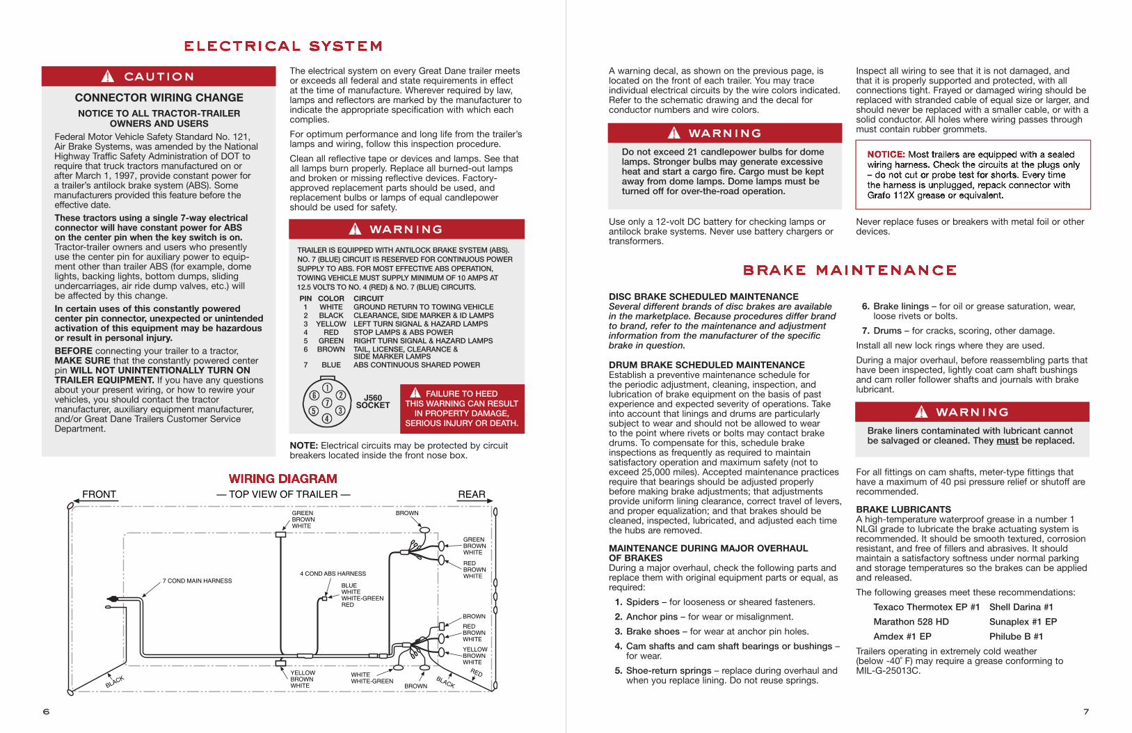
A warning decal, as shown on the previous page, islocated on the front of each trailer. You may trace individual electrical circuits by the wire colors indicated.Refer to the schematic drawing and the decal for conductor numbers and wire colors.
Use only a 12-volt DC battery for checking lamps orantilock brake systems. Never use battery chargers ortransformers.
Inspect all wiring to see that it is not damaged, and that it is properly supported and protected, with all connections tight. Frayed or damaged wiring should bereplaced with stranded cable of equal size or larger, andshould never be replaced with a smaller cable, or with asolid conductor. All holes where wiring passes throughmust contain rubber grommets.
Never replace fuses or breakers with metal foil or otherdevices.
DISC BRAKE SCHEDULED MAINTENANCESeveral different brands of disc brakes are available in the marketplace. Because procedures differ brand to brand, refer to the maintenance and adjustmentinformation from the manufacturer of the specificbrake in question.
DRUM BRAKE SCHEDULED MAINTENANCEEstablish a preventive maintenance schedule for the periodic adjustment, cleaning, inspection, and lubrication of brake equipment on the basis of pastexperience and expected severity of operations. Takeinto account that linings and drums are particularly subject to wear and should not be allowed to wear to the point where rivets or bolts may contact brakedrums. To compensate for this, schedule brake inspections as frequently as required to maintain satisfactory operation and maximum safety (not toexceed 25,000 miles). Accepted maintenance practicesrequire that bearings should be adjusted properlybefore making brake adjustments; that adjustmentsprovide uniform lining clearance, correct travel of levers,and proper equalization; and that brakes should becleaned, inspected, lubricated, and adjusted each timethe hubs are removed.
MAINTENANCE DURING MAJOR OVERHAUL OF BRAKESDuring a major overhaul, check the following parts andreplace them with original equipment parts or equal, asrequired:
1. Spiders – for looseness or sheared fasteners.
2. Anchor pins – for wear or misalignment.
3. Brake shoes – for wear at anchor pin holes.
4. Cam shafts and cam shaft bearings or bushings –for wear.
5. Shoe-return springs – replace during overhaul andwhen you replace lining. Do not reuse springs.
6. Brake linings – for oil or grease saturation, wear,loose rivets or bolts.
7. Drums – for cracks, scoring, other damage.
Install all new lock rings where they are used.
During a major overhaul, before reassembling parts thathave been inspected, lightly coat cam shaft bushingsand cam roller follower shafts and journals with brakelubricant.
For all fittings on cam shafts, meter-type fittings thathave a maximum of 40 psi pressure relief or shutoff arerecommended.
BRAKE LUBRICANTSA high-temperature waterproof grease in a number 1NLGI grade to lubricate the brake actuating system isrecommended. It should be smooth textured, corrosionresistant, and free of fillers and abrasives. It shouldmaintain a satisfactory softness under normal parkingand storage temperatures so the brakes can be appliedand released.
The following greases meet these recommendations:
Texaco Thermotex EP #1 Shell Darina #1
Marathon 528 HD Sunaplex #1 EP
Amdex #1 EP Philube B #1
Trailers operating in extremely cold weather (below -40˚ F) may require a grease conforming to MIL-G-25013C.
7
The electrical system on every Great Dane trailer meetsor exceeds all federal and state requirements in effectat the time of manufacture. Wherever required by law,lamps and reflectors are marked by the manufacturer toindicate the appropriate specification with which eachcomplies.
For optimum performance and long life from the trailer’slamps and wiring, follow this inspection procedure.
Clean all reflective tape or devices and lamps. See thatall lamps burn properly. Replace all burned-out lampsand broken or missing reflective devices. Factory-approved replacement parts should be used, andreplacement bulbs or lamps of equal candlepowershould be used for safety.
NOTE: Electrical circuits may be protected by circuitbreakers located inside the front nose box.
6
GREENBROWNWHITE
YELLOWBROWNWHITE
WHITEWHITE-GREEN
BROWN
BROWN
GREENBROWNWHITE
REDBROWNWHITE
BROWN
RED
RED
BROWNWHITE
YELLOWBROWNWHITE
7 COND MAIN HARNESS4 COND ABS HARNESS
— TOP VIEW OF TRAILER —FRONT REAR
BLUEWHITEWHITE-GREENRED
electrical system
brake maintenance
WIRING DIAGRAM
warningDo not exceed 21 candlepower bulbs for domelamps. Stronger bulbs may generate excessiveheat and start a cargo fire. Cargo must be keptaway from dome lamps. Dome lamps must beturned off for over-the-road operation.
cautionCONNECTOR WIRING CHANGENOTICE TO ALL TRACTOR-TRAILER
OWNERS AND USERSFederal Motor Vehicle Safety Standard No. 121, Air Brake Systems, was amended by the NationalHighway Traffic Safety Administration of DOT torequire that truck tractors manufactured on orafter March 1, 1997, provide constant power for a trailer’s antilock brake system (ABS). Some manufacturers provided this feature before theeffective date. These tractors using a single 7-way electricalconnector will have constant power for ABS on the center pin when the key switch is on.Tractor-trailer owners and users who presently use the center pin for auxiliary power to equip-ment other than trailer ABS (for example, domelights, backing lights, bottom dumps, slidingundercarriages, air ride dump valves, etc.) will be affected by this change.In certain uses of this constantly powered center pin connector, unexpected or unintendedactivation of this equipment may be hazardousor result in personal injury. BEFORE connecting your trailer to a tractor,MAKE SURE that the constantly powered centerpin WILL NOT UNINTENTIONALLY TURN ONTRAILER EQUIPMENT. If you have any questionsabout your present wiring, or how to rewire yourvehicles, you should contact the tractor manufacturer, auxiliary equipment manufacturer,and/or Great Dane Trailers Customer ServiceDepartment.
NOTICE: Most trailers are equipped with a sealedwiring harness. Check the circuits at the plugs only– do not cut or probe test for shorts. Every timethe harness is unplugged, repack connector withGrafo 112X grease or equivalent.
warningBrake liners contaminated with lubricant cannotbe salvaged or cleaned. They must be replaced.
warningTRAILER IS EQUIPPED WITH ANTILOCK BRAKE SYSTEM (ABS).NO. 7 (BLUE) CIRCUIT IS RESERVED FOR CONTINUOUS POWERSUPPLY TO ABS. FOR MOST EFFECTIVE ABS OPERATION, TOWING VEHICLE MUST SUPPLY MINIMUM OF 10 AMPS AT 12.5 VOLTS TO NO. 4 (RED) & NO. 7 (BLUE) CIRCUITS.
PIN COLOR CIRCUIT1 WHITE GROUND RETURN TO TOWING VEHICLE2 BLACK CLEARANCE, SIDE MARKER & ID LAMPS3 YELLOW LEFT TURN SIGNAL & HAZARD LAMPS4 RED STOP LAMPS & ABS POWER5 GREEN RIGHT TURN SIGNAL & HAZARD LAMPS6 BROWN TAIL, LICENSE, CLEARANCE &
SIDE MARKER LAMPS7 BLUE ABS CONTINUOUS SHARED POWER
J560SOCKET
FAILURE TO HEED THIS WARNING CAN RESULT
IN PROPERTY DAMAGE, SERIOUS INJURY OR DEATH.
The trailer brake system will perform safely and efficiently only as long as it is properly maintained and not abused. Trailer brakes should be inspected frequently in connection with a Trailer PreventiveMaintenance (TPM) Program. Out-of-adjustment brakescan cause increased stopping distance, shorter brakecomponent life, and a greater tendency for the trailer to jackknife.
AIR SYSTEM AND BRAKE OPERATIONProper operation of the brake systems requires a firm seal between the air brake couplers. Inspect thecouplers for seal damage and cracked housings. Somecouplers are equipped with filters. These filters must becleaned at regular intervals to prevent malfunction ofthe brake systems. Inspect the air hoses for crackingand for frayed connections. Be sure air hoses are notrubbing on any metal surface or each other. Replace orrepair damaged components.
Keep the air system clean. All air tanks should be draineddaily to remove moisture and other contaminants. SeeFreezing Weather Maintenance.
Some air valve manufacturers discourage the use of airline antifreeze. Use may result in deterioration of sealsin these valves.
If you use Teflon tape or other thread sealers to sealthreaded connections in your air lines, be careful not to allow pieces of the sealer to enter the air system. It can clog passages into the valves and cause them to malfunction.
Keep the air system tight. The air system cannot becharged properly if there are leaks in reservoirs, lines,hoses, or valves. Always check the tractor pressuregauge for unusual drops or extended buildup times.
Run the tractor engine until the air brake system pressure gauge shows at least 105 psi. Listen for airleaks. With the engine off, check the gauge reading with no brakes applied. The gauge reading loss shouldnot exceed three psi in one minute.
With the engine still off, apply the brakes fully for twominutes. The gauge reading drop should not exceedfour psi in one minute.
With engine still off, slowly open drain cocks in the trailer’s air tanks and allow the pressure to drop gradually.In a system employing spring brake control valves, thespring brakes should function and apply the brakes.
In a system that does not employ spring brake controlvalves, the relay emergency valve should function andapply the brakes.
A schedule for periodic cleaning, inspection, adjustmentand lubrication of brake equipment should be estab-lished by the operator, based on past experience andseverity of operation.
BRAKE SHOESBrake shoe designs vary, depending on the type ofbrake and brake manufacturer. Some brakes requirespecial tools. If you have problems removing brakeshoes, refer to the brake manufacturer’s manual.
BRAKE SHOE SPRINGSReplace weak or unmated brake shoe springs wheneverthey cause pulling or dragging brakes. The springs areconstantly expanding and contracting in the confinedhot area of the brake drums. Excessive heat duringexpansion will cause them to weaken.
BRAKE LINERSThe certified Gross Axle Weight Rating (GAWR) in manycases is determined by the friction level of the brake liners. The friction level is determined by the axle andvehicle manufacturer to provide the required braketorque as prescribed by governmental regulations.
REFACING DRUMIt is not a good practice to reface brake drums. Refacingcan weaken the drums, making them unable to dissipateall the heat generated by brake applications, and makingthem susceptible to distortion and heat cracks.
If brake drums must be refaced on cam-type brakes,when oversized linings are used, precautions regardingcam travel should be checked to prevent sticking camsor cam rollover. This problem often exists when the linings become worn. It may be necessary to installoversized rollers to prevent this problem.
OVERSIZE LINERSTo compensate for material removed when refacingbrake drums, X (1/16" oversize) and XX (1/8" oversize)liners are furnished by the lining manufacturers. Whenoversize liners are used the drums should be machinedin increments of 1/16" (radius increased 1/16").
BRAKE SHOE ROLLER CAM FOLLOWERSRoller cam followers are available in four sizes, eachhaving been designed for a specific purpose.
STANDARD SIZE (1.250")Standard rollers are used when installing standard lining with standard drums, X lining with 1/16" oversizedrums, or XX lining with 1/8" oversize drums.
If the drums have been refaced and oversize rollers laterinstalled, the oversize rollers must be removed andstandard rollers installed when the new liners areinstalled.
1/8" OVERSIZE (1.375")Use 1/8” oversize cam followers when you install standard liners with worn or trued drums that are 1/32"oversize. Circle grind the liners a few thousandths lessthan the drum diameter.
1/4" OVERSIZE (1.500")Use 1/4” oversize cam followers when X liners havebeen installed with 1/16" oversize drums and standardrollers. The standard rollers should be removed and1/4" oversize installed before the lining becomes wornto the point when the brake cam is no longer effective.
1/2" OVERSIZE (1.750")Use 1/2” oversize cam followers when XX liners and1/8" oversize drums have been used. The standardrollers should be removed when the liners becomeapproximately 50% worn, and 1/2" oversize rollersshould be installed.
CAM PLATE SHIMSWhen standard liners are installed with worn or trueddrums, or when X or XX liners have been installed andare approximately 50% worn, shims or a combination ofshims should be installed under each of the cam wearplates to permit the cam to be returned to the fullrelease position. Shims are available in 1/64", 1/32" and1/16" thicknesses.
BRAKE DUST SHIELDSThe brake spiders used for mounting the brake shoeassembly parts also become the mounting for optionaldust shields.
The use of dust shields should be determined by conditions encountered by the trailer. Operations inmud, sand, dirt, water, and other forms of foreign materials should be the governing factors. When theseconditions exist during winter months and maximumcooling is desirable during summer months, dustshields are easily installed or removed.
AUTOMATIC ADJUSTERSSeveral different brands of automatic adjusters arecommon. Because adjustment differs, refer to the maintenance and adjustment information from the manufacturer.
Some automatic slacks are equipped with an adjust-ment pawl which eliminates loss of adjustment. Thispawl must be removed prior to backing off on theadjustment to prevent damage to the splined pawl and adjusting screw.
8 9
brake care and adjustment
brake adjusters
warningSerious air leaks in the trailer’s braking systemare hazardous conditions that require the trailerto be placed out of service until they are properly corrected.
warningEnlarging the drum diameter may permit thecam to rotate beyond its maximum lift when thelining becomes worn. This can result in stickingcams or cam rollover.
To avoid this condition and to obtain maximumlining wear, oversize roller cam followers orwear plate shims (depending on the brakedesign) should be installed when the linersbecome approximately 50% worn.
warningPrior to performing maintenance on any airbrake system component, chock the wheels.The system air pressure should be exhaustedby opening the reservoir drain cocks.
NOTICE: When replacing liners, be sure to use liners with the same friction level as those removedfrom the trailer so that the GAWR is not reduced.
NOTICE: Failure to use dust shields during monthswhere gravel chips, etc., are used on roads mayallow drums to be scored by these materials. Dustshields may provide the desired protection.
NOTICE: Automatic adjusters may seem to be over-adjusting and may seem to be more sensitiveuntil brakes are properly burnished.
All axles (except some converter dolly axles) areequipped with air/spring actuators. Each actuator isseparated into two units. The base unit applies theservice brakes. The top unit contains a coil spring thatmust be compressed by air within the chamber torelease the parking brakes. Loss of air pressure in thesupply line to the brake chamber will automaticallyapply parking and/or emergency braking.
In case of a service brake system air failure, when thespring brakes are applied in an emergency stop, aspring brake air reservoir retains enough stored air torelease the spring brakes at least once by means of thetractor parking brake control.
In the absence of air pressure, a manual release is pro-vided to allow release of the spring brake (see followinginstructions).
To manually release parking brake actuators:
1. Always position wheel chocks at both front and rearof tires before manually releasing parking brakes.
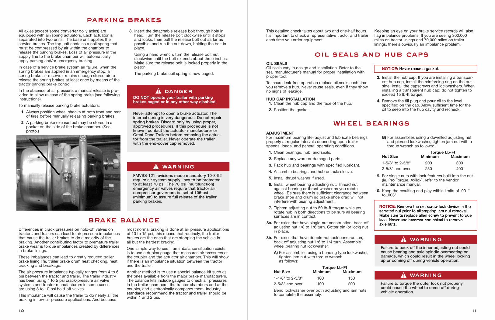
2. A parking brake release tool may be stored in apocket on the side of the brake chamber. (Seephoto.)
3. Insert the detachable release bolt through hole inhead. Turn the release bolt clockwise until it stopsand locks, then pull the release bolt out as far aspossible, and run the nut down, holding the bolt inplace.
Using a hand wrench, turn the release bolt nutclockwise until the bolt extends about three inches.Make sure the release bolt is locked properly in thepiston.
The parking brake coil spring is now caged.
Differences in crack pressures on hold-off valves ontractors and trailers can lead to air pressure imbalancesthat cause the trailer brakes to do a majority of thebraking. Another contributing factor to premature trailerbrake wear is torque imbalances created by differencesin brake linings.
These imbalances can lead to greatly reduced trailerbrake lining life, trailer brake drum heat checking, heatcracking and breakage.
The air pressure imbalance typically ranges from 4 to 6psi between the tractor and trailer. The trailer industryhas been using 4 to 5 psi crack-pressure air valve systems and tractor manufacturers in some cases are using 8 to 10 psi hold-off valves.
This imbalance will cause the trailer to do nearly all thebraking in low-air pressure applications. And because
most normal braking is done at air pressure applicationsof 10 to 15 psi, this means that routinely, the trailerbrakes are the ones that are stopping the vehicle in all but the hardest braking.
One simple way to see if an imbalance situation existsis to use a duplex gauge that measures air pressures atthe coupler and the actuator air chamber. This will showif there is an imbalance situation between the tractorand the trailer.
Another method is to use a special balance kit such asthe ones available from the major brake manufacturers.The balance kits include gauges to check air pressuresin the trailer chambers, the tractor chambers and at thecoupler, and electronically compares them. Industrystandards recommend the tractor and trailer should bewithin 1 and 2 psi.
ADJUSTMENTFor maximum bearing life, adjust and lubricate bearingsproperly at regular intervals depending upon trailerspeeds, loads, and general operating conditions.
1. Clean bearings, hub, and seals.
2. Replace any worn or damaged parts.
3. Pack hub and bearings with specified lubricant.
4. Assemble bearings and hub on axle sleeve.
5. Install thrust washer if used.
6. Install wheel bearing adjusting nut. Thread nutagainst bearing or thrust washer as you rotatewheel. Be sure there is sufficient clearance betweenbrake shoe and drum so brake shoe drag will notinterfere with bearing adjustment.
7. Tighten adjusting nut to 50 lb-ft torque while yourotate hub in both directions to be sure all bearingsurfaces are in contact.
8a. For axles that have single-nut construction, back offadjusting nut 1/8 to 1/6 turn. Cotter pin (or lock) nutin place.
8b. For axles that have double-nut lock construction,back off adjusting nut 1/6 to 1/4 turn. Assemblewheel bearing nut lockwasher.
A) For assemblies using a bending type lockwasher,tighten jam nut with torque wrench as follows:
Torque Lb-FtNut Size Minimum Maximum
1-1/8" to 2-5/8" 100 1502-5/8" and over 100 200
Bend lockwasher over both adjusting and jam nuts to complete the assembly.
B) For assemblies using a dowelled adjusting nutand pierced lockwasher, tighten jam nut with atorque wrench as follows:
Torque Lb-FtNut Size Minimum Maximum
1-5/8" to 2-5/8" 200 3002-5/8" and over 250 400
9. For single nuts with lock features built into the nut(ie. Pro Torque, Axilok), refer to the vendor maintenance manual.
10. Keep the resulting end play within limits of .001" to .003".
This detailed check takes about two and one-half hours.It’s important to check a representative tractor and trailereach time you order equipment.
Keeping an eye on your brake service records will alsoflag imbalance problems. If you are seeing 300,000miles on tractor linings and 70,000 miles on trailer linings, there’s obviously an imbalance problem.
10 11
parking brakes
wheel bearings
brake balance
dangerDO NOT operate your trailer with parkingbrakes caged or in any other way disabled.
Never attempt to open a brake actuator. Theinternal spring is very dangerous. Do not repairspring brakes. Discard only by using proper,approved procedures. If this procedure is notknown, contact the actuator manufacturer orGreat Dane Trailers before removing the actua-tor from the trailer. Never operate the trailerwith the end-cover cap removed.
warningFailure to back off the inner adjusting nut couldcause bearing and axle spindle overheating ordamage, which could result in the wheel lockingup or coming off during vehicle operation.
warningFMVSS-121 revisions made mandatory 10-8-92require air system supply lines to be protectedto at least 70 psi. The 70 psi (multifunction)emergency air valves require that tractor aircompressor governors be set at 105 psi (minimum) to assure full release of the trailerparking brakes.
warningFailure to torque the outer lock nut properlycould cause the wheel to come off during vehicle operation.
NOTICE: Remove the set screw lock device in theserrated nut prior to attempting jam nut removal.Make sure to replace allen screw to prevent torqueloss. Never use hammer and chisel to remove axle nuts.
OIL SEALSOil seals vary in design and installation. Refer to theseal manufacturer’s manual for proper installation withproper tool.
To insure leak-free operation replace oil seals each timeyou remove a hub. Never reuse seals, even if they showno signs of leakage.
HUB CAP INSTALLATION1. Clean the hub cap and the face of the hub.
2. Position the gasket.
3. Install the hub cap. If you are installing a transpar-ent hub cap, install the reinforcing ring on the out-side. Install the capscrews and lockwashers. Wheninstalling a transparent hub cap, do not tighten toexceed 15 lb-ft torque.
4. Remove the fill plug and pour oil to the level specified on the cap. Allow sufficient time for the oil to seep into the hub cavity and recheck.
oil seals and hub caps
NOTICE: Never reuse a gasket.
Check wear pads in hangers. If they are wearing thin,install new pads or the spring will cause permanentdamage to the hanger. Do not operate with brokenspring leaves.
Check to see if all springs can make proper contactwith wear pads. Twisted springs and cocked hangerscan cause uneven spring contact with wear pads, andwill result in excessive wear on the suspension.
Check to see if there is sufficient clearance betweenthe springs and the sides of the hangers and rockers.Improper spring centers or hanger spacing can createbinding in this area, resulting in excessive wear.
Check the equalizer to see that there are no obstruc-tions to movement during operations. If equalizer move-ment is restricted by an obstruction, the axle “walk” willnot be sufficient and damage will result.Check the rock-er beam to see if there is adequate clearance betweenthe ends of the spring and the rocker beam hub whenthe axle is both loaded and unloaded.
Check welds to see that no cracking has occurredbetween the spring seats and axles, and between the hangers and sub-frame.
Threaded fasteners should be checked for proper tightness after an initial break-in period of 3,000 to5,000 miles. Torque should be rechecked every 25,000 miles.
The replacement of worn bushings is considered normal preventative maintenance. Bushings showingsigns of wear should be replaced before they damagethe parts they are pressed into. Routine torque maintenance will prolong the life of bushings.
AIR-SPRING SUSPENSIONThe air-spring suspension height is controlled by heightcontrol valves that maintain a constant trailer height bypressurizing or exhausting air in the air springs as needed to support the load being carried.
You must build up to and maintain your trailer’s air pressure at more than 70 psi for van trailers and 80 psifor platform trailers before operating the trailer. The airprotection valve will not operate until you have 70 psion van trailer and 80 psi on platform trailers in the system. This valve automatically maintains a safe airbrake pressure higher than 70 psi for van trailers and 80 psi for platform trailers in the event of an air loss due to a failure in the suspension system.
If an air-spring failure occurs on one side, it is recommended to completely deflate the suspensionand temporarily operate on the air springs’ internal rubber bumpers to allow your trailer to be moved to a shop for repairs.
To deflate or cut off the air pressure to the damaged air spring, disconnect the height control valve actuatinglevers from their link assemblies and rotate to the vertical down position.
Check air lines and fittings for leaks.
Check air springs and proper clearance when inflated –minimum clearance is 1 3/4".
Check axle clamp group to be sure that all bolted connections are properly torqued. For proper torquerequirement refer to the suspension manufacturer’smaintenance manual. Worn component parts or looseU-bolts can allow the vehicle to roll or sway.
Excessive play in the beam pivot connection area cancause premature tire wear and erratic handling characteristics. Loose bolts at this connection willcause the rubber bushings to wear out prematurely.
INSPECTIONInspect the inner and outer wheel bearing cups, conesand rollers for excessive wear or damage.
Refer to bearing and axle manufacturer’s manuals forinspection and replacement requirements.
LUBRICATIONFor maximum bearing life, inspect wheel bearings andlubricant periodically, change lubricant regularly, andclean the hub assembly properly.
If you do not clean the hub assembly properly bothoriginally and in subsequent service, you must adhereto a shorter lube change schedule. When adding oil orchecking oil level, be certain to clean the cap and plugbefore disassembling, to help keep out dirt and roadgrime.
When you clean and dry parts or bearings for later use,pack and coat them with wheel bearing lubricant andwrap in clean waxed paper to prevent surface corrosion that might cause premature bearing failure.
1. Remove wheel hub and bearing cones. Clean allold grease or oil from wheel hub, bearing cones,and hub cap with kerosene or diesel fuel oil and astiff fiber (not steel) brush.
2. Allow the cleaned parts to dry, or dry them with aclean absorbent cloth or paper. Grease and oil will not adhere to and protect a surface wet withsolvent. The solvent may dilute the lubricant. Clean and dry your hands and all tools.
3. Inspect oil seals, oil seal wiping surfaces, bearings,and bearing cups for indications of wear or damage.Replace any worn or damaged parts. Handle thebearing carefully during inspection (and packing, ifgrease is used) so the cage will not be bent or therollers and cone damaged.
GREASE-LUBRICATED WHEEL BEARINGDepending on operating conditions, speed, and loads,change lubricants whenever you replace seals, whenyou reline brakes, or every 100,000 miles (or Spring andFall if yearly mileage is less).
At rebuild time, before you install wheel bearings onto spindle, coat bearing journals (to deter fretting corrosion) with a film of Lithium, 12-Hydroxy stearategrease or its equivalent.
When you service grease-lubricated wheel bearings:
1. Pack bearing with pressure packer, if possible. Ifnot, pack by hand, forcing the grease into the cavi-ties between the rollers and cage from the largeend of the cone.
2. Pack the hub between the two bearing cups withgrease to the level of the smallest diameter of thecup.
3. Assemble the hub and bearings on the axle, beingcareful not to damage the oil seals or bearing. Adjust the bearings.
OIL-LUBRICATED WHEEL BEARINGCheck oil-lubricated wheel bearings every 1,000 miles.
Change oil when you replace seals, when you relinebrakes, or at least once a year. Use a gear-type oil: SAE140 if temperature is above freezing, SAE 90 if tempera-ture is below freezing, or a multipurpose oil with an SAErange of 85 to 140 for year-round conditions.
SERVICEWhen you service oil-lubricated wheel bearings:
1. Wipe a film of oil on the bearing spindle to preventrust behind the inner bearing cone.
2. Assemble the hub and bearings on the axle, beingcareful not damage the oil seals or bearings. Adjustthe bearings.
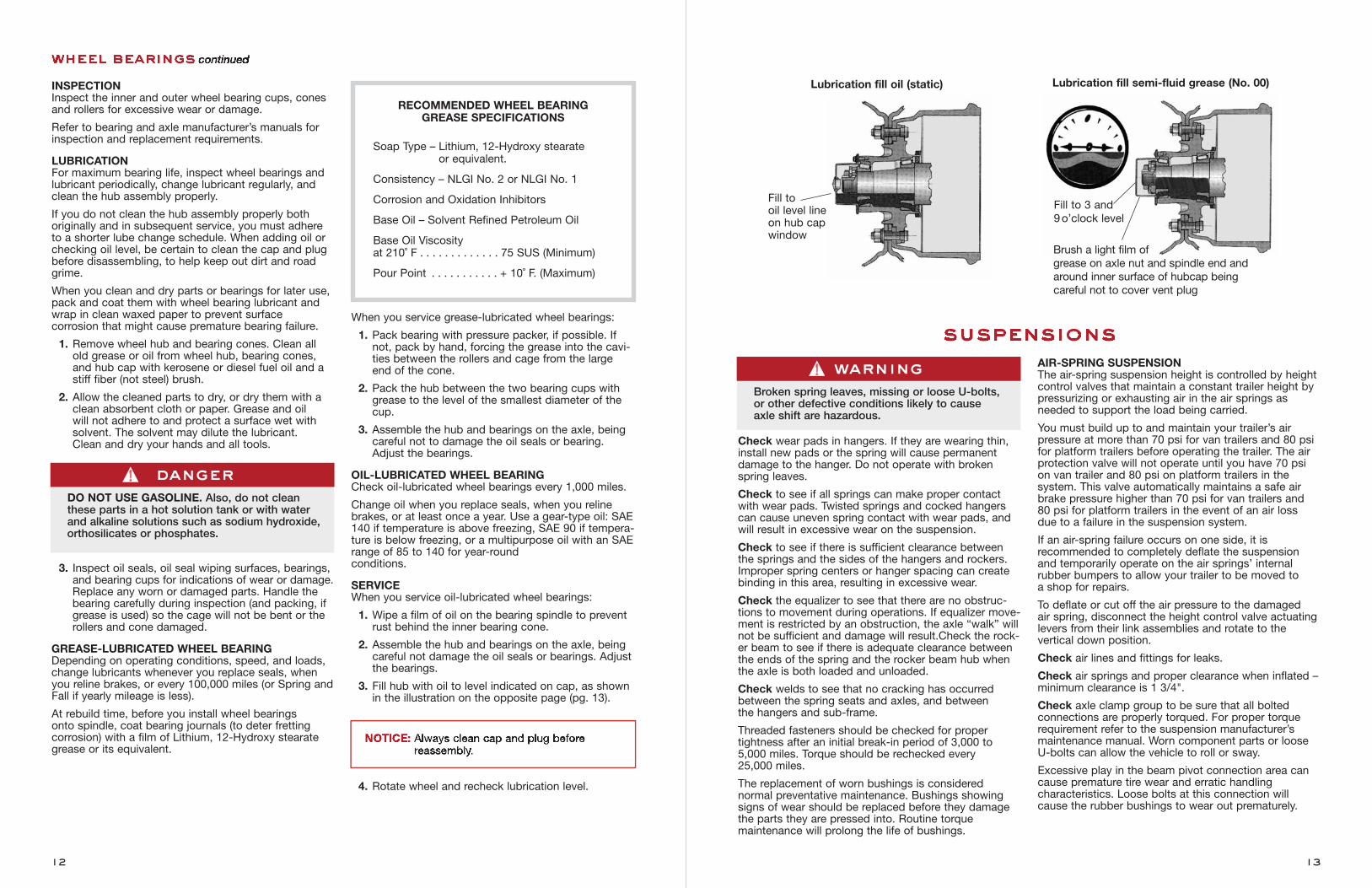
3. Fill hub with oil to level indicated on cap, as shownin the illustration on the opposite page (pg. 13).
4. Rotate wheel and recheck lubrication level.
RECOMMENDED WHEEL BEARING GREASE SPECIFICATIONS
Soap Type – Lithium, 12-Hydroxy stearate or equivalent.
Consistency – NLGI No. 2 or NLGI No. 1
Corrosion and Oxidation Inhibitors
Base Oil – Solvent Refined Petroleum Oil
Base Oil Viscosity at 210˚ F . . . . . . . . . . . . . 75 SUS (Minimum)
Pour Point . . . . . . . . . . . + 10˚ F. (Maximum)
12 13
dangerDO NOT USE GASOLINE. Also, do not cleanthese parts in a hot solution tank or with waterand alkaline solutions such as sodium hydroxide,orthosilicates or phosphates.
NOTICE: Always clean cap and plug beforereassembly.
wheel bearings continued
Fill to oil level lineon hub capwindow
Lubrication fill oil (static) Lubrication fill semi-fluid grease (No. 00)
Brush a light film of grease on axle nut and spindle end andaround inner surface of hubcap being careful not to cover vent plug
Fill to 3 and 9o’clock level
warningBroken spring leaves, missing or loose U-bolts,or other defective conditions likely to causeaxle shift are hazardous.
suspensions
The shock absorbers should be replaced at the firstsign of leaking hydraulic fluid. Worn shocks will allowtire hop and yield poor handling characteristics.
Many air suspensions are equipped with air controlkits. The air control kit allows the raising or lowering of the vehicle bed by inflating or exhausting air fromthe air suspension. Do NOT operate the vehicle whenthe suspension is in the lowered or raised position.
Improperly maintained air suspensions will result intrailer suspension damage which includes bushingwear and irregular tire wear.
By customer specification, Great Dane may haveinstalled any of the following air-spring suspensions onyour new trailers.
Neway or SAF Holland modelsReyco modelsHendrickson modelsMeritor modelsTuthill models
Please reference the bibliography in the back of themanual to obtain address for ordering manufacturer-specific maintenance manuals.
LEAF-SPRING SUSPENSIONCheck the torque of all suspension bolts after initialbreak-in period on the road and thereafter at regularintervals not to exceed 25,000 miles. Follow thetorquing recommendations of the suspension manufacturer. If they are not available, use the follow-ing table of torque recommendations for clean drythreads. The use of lubricants will apply more tensileforce for the same torque. If lubricants are used,decrease torque approximately 30%.
1" 14 UNC 350 -375 lb-ft7/8" 14 UNF 275 -300 lb-ft5/8" 18 UNF 75 -90 lb-ft5/8" 18 UNF 125 -155 lb-ft (step bolts)1/2" 45 -50 lb-ft
It is especially important to maintain torque on U-bolts,equalizer bolts, and torque arm bolts. Torque the nutside of torque arm bolts only. Torquing the bolt headswill not produce the desired clamping force.
Inspection of upper running gear rail weld attachmentto the trailer for weld fatigue cracks is a requirement ofthe annual FMCSA inspection. All trailer structuresshould be inspected for weld fatigue cracks and/orloose fasteners and any found should be corrected asa part of routine PM (preventative maintenance) serv-ice. Any defects in a trailer should be corrected to themanufacturer specifications before the trailer isreturned to service.
FIXED SUSPENSION1. If the trailer is equipped with a fixed suspension,visually check all bolts connecting the suspensionframe assembly to the upper running gear rails.
2. If these bolts need replacing, use only Grade 5 (minimum) bolts with Grade B (minimum) locking-type nuts. Be careful in selecting the proper boltgrip length so that threads are not at the interfaceof the rail/frame joint.
SERVICING RIMS & WHEELSFor information on servicing wheels and rims, refer toOSHA 29 CFR 1910.177 and to the appropriate wheeland rim manufacturer’s manuals. Also refer toServicing Single-Piece and Multi-Piece Rim Wheels,U.S. Department of Labor pamphlet, OSHA 3086 andthe accompanying two chart set, available from OSHAregional offices.
14 15
SINGLE-PIECE RIM WHEELSIllustrated, complete safe operating procedures are provided on the wall chart “Mounting and DemountingProcedures for Truck/Bus Tires” available from theDepartment of Transportation, and OSHA.
The following minimum steps are recommended to provide maximum safety when servicing single-piecewheels:
• The tire must be completely deflated by theremoval of the valve core before demounting.
• Mounting and demounting of the tire must be per-formed only from the narrow ledge side of thewheel. Care must be taken to avoid damaging thetire beads, and the tire must be mounted only on acompatible wheel of mating bead diameter andwidth. Proper tools must be used.
• A non-flammable bead lubricant must be applied tobead and wheel mating surfaces before assem-bling, unless the wheel manufacturer recommendsagainst the use of any lubricant.
• If a tire changing machine is used, the tire may beinflated only to the minimum pressure necessary toforce the tire bead onto the rim ledge and create anairtight seal before removal from the tire changingmachine.
• If a bead expander is used, it must be removedbefore the valve core is installed and as soon as therim wheel becomes airtight (when the tire beadslips onto the bead seat).
• The tire must always be inflated within a restrainingdevice/safety cage.
• The tire must not be inflated to more than the cold-inflation pressure molded in the sidewall unless ahigher pressure is recommended by the manufac-turer.
• Cracked, broken, bent, or otherwise damagedwheels must not be reworked, welded, braced, orother wise heated.
1. Check all metal surfaces thoroughly, including areabetween duals and on inboard side of wheel. Watch for:
a. Excessive rust or corrosion buildup
b. Cracks in metal
c. Bent flanges, resulting from road obstructions
d. Deep rim tool marks on rings or in gutter areas
e. Loose, missing or damaged nuts or clamps
f. Bent or stripped studs
g. Damaged or missing rim drive plates
h. Mismatched rim parts
2. Remove damaged rims or wheels.
3. Mark damaged or hazardous areas so that part willbe removed from service.
4. Replace damaged parts. Insure that replacementsare made with the proper sizes and types of rimwheels.
5. Inflate tires only to recommended air pressures.
suspensions continued
running gear assembly rim and wheel inspectionand maintenance
NOTICE: Loose U-bolts can result in spring damage. Improperly torqued bushing bolts can produce premature bushing wear.
dangerTires must only be inflated while in a restrainingdevice/safety cage.
dangerBe sure that replacements are made with theproper sizes and types of rim wheels.
warningTire and wheel/rim servicing can be extremelydangerous and must be done only by trainedpersonnel using proper tools and procedures.Information about tire and wheel servicing canbe obtained from:
US Department of LaborOSHA Publications Office200 Constitution Ave, NWRoom Number N3626 Washington, DC 20210Telephone: 800-321-6742
NHTSAAuto Safety Hotline1200 New Jersey Avenue, SEWashington, DC 20590Telephone: 800-424-99153
warningExcessively corroded or cracked rims or ringscan be dangerous. Deflate tires prior to theremoval of rims or wheels from vehicle.
www.safercar.gov
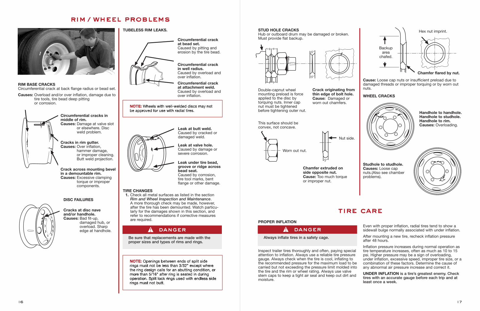
RIM BASE CRACKSCircumferential crack at back flange radius or bead set.
Causes: Overload and/or over inflation, damage due totire tools, tire bead deep pitting or corrosion.
Circumferential cracks in middle of rim.Causes: Damage at valve slot
or elsewhere. Discweld problem.
Cracks in rim gutter.Causes: Over inflation,
hammer damage, or improper cleaning.Butt weld projection.
Crack across mounting bevelin a demountable rim.Causes: Excessive clamping
torque or improper components.
DISC FAILURES
Cracks at disc nave and/or handhole.Causes: Bad fit-up,
damaged hub, oroverload. Sharpedge at handhole.
TUBELESS RIM LEAKS.
Circumferential crackat bead set.Caused by pitting anderosion by the tire bead.
Circumferential crackin well radius.Caused by overload andover inflation.
Circumferential crackat attachment weld. Caused by overload andover inflation.
Leak at butt weld.Caused by cracked ordamaged weld.
Leak at valve hole.Caused by damage orsevere corrosion.
Leak under tire bead,groove or ridge acrossbead seat.Caused by corrosion,tire tool marks, bentflange or other damage.
TIRE CHANGES1. Check all metal surfaces as listed in the section
Rim and Wheel Inspection and Maintenance. A more thorough check may be made, however, after the tire has been demounted. Watch particu-larly for the damages shown in this section, andrefer to recommendations if corrective measuresare required.
STUD HOLE CRACKSHub or outboard drum may be damaged or broken.Must provide flat backup.
Double-capnut wheel mounting preload is forceapplied to the disc by torquing nuts. Inner cap nut must be tightened before tightening outer nut.
This surface should be convex, not concave.
Cause: Loose cap nuts or insufficient preload due todamaged threads or improper torquing or by worn outnuts.
WHEEL CRACKS
Handhole to handhole.Handhole to studhole.Handhole to rim.Causes: Overloading.
Studhole to studhole.Causes: Loose cap nuts.(Also see chamberproblems).
Crack originating fromthin edge of bolt hole. Cause: Damaged orworn out chamfers.
Nut side.
Chamfer flared by nut.
Hex nut imprint.
Worn out nut.
Backup area chafed.
Chamfer extruded onside opposite nut. Cause: Too much torqueor improper nut.
17
rim / wheel problems
tire care
NOTE: Wheels with well-welded discs may notbe approved for use with radial tires.
NOTE: Openings between ends of split siderings must not be less than 3/32" except wherethe ring design calls for an abutting condition, ormore than 5/16" after ring is seated in duringoperation. Split lock rings used with endless siderings must not butt.
dangerBe sure that replacements are made with theproper sizes and types of rims and rings.
16
PROPER INFLATION
Inspect trailer tires thoroughly and often, paying specialattention to inflation. Always use a reliable tire pressuregauge. Always check when the tire is cool, inflating tothe recommended pressure for the maximum load to becarried but not exceeding the pressure limit molded intothe tire and the rim or wheel rating. Always use valvestem caps to keep a tight air seal and keep out dirt andmoisture.
Even with proper inflation, radial tires tend to show asidewall bulge normally associated with under inflation.
After mounting a new tire, recheck inflation pressureafter 48 hours.
Inflation pressure increases during normal operation astire temperature increases, often as much as 10 to 15psi. Higher pressure may be a sign of overloading,under inflation, excessive speed, improper tire size, or acombination of these factors. Determine the cause ofany abnormal air pressure increase and correct it.
UNDER INFLATION is a tire’s greatest enemy. Checktires with an accurate gauge before each trip and atleast once a week.
dangerAlways inflate tires in a safety cage.
Running a tire under inflated can have serious consequences in addition to reducing tread life. Heatbuildup can cause the tire body to deteriorate, resultingin separation of the tread from the body or belt ply. Asoft tire overdeflects, causing fatigue breaks in the bodycords. Continued overdeflection causes breaks in thebody cord construction, leading to sudden air loss.
Running duals with one tire flat or severely underinflated will lead to intense heat buildup in the flat orlow tire due to external and internal friction – to theextent that the casing will likely burst into flames.Also, one tire of a dual running flat or low means theother is overloaded and may fail.
OVER INFLATION can also cause serious damage to a tire. Because a tire is more rigid when over inflated, itdoes not absorb road shocks as well. This can lead tobody breaks when impacting a bump or chuckhole. It can stress the rim, leading to rim failure. And overinflated tires are more likely to cut, snag, and puncture.
PROPER MATCHING AND SPACING OF DUALSMismatched dual tires force the larger diameter tire toan overload condition, causing it to overdeflect andoverheat. The smaller diameter tire will lack completeroad contact and will wear faster and more irregularly.Tread or ply separation, tire body breaks, and blowoutscan develop from mismatching duals.
Permissible diameter differences between a tire and itsdual mate having equal inflation pressure are:
1/4" for 8.25 cross section (tubeless 9-22.5) and smaller sizes
1/2" for 9.00 cross section (tubeless 10-22.5)and larger sizes
To determine the difference in diameter measure thetires forty-eight hours after initial inflation with a steeltape. Measurements on the trailer can be made bystring gauge, straight edge, tire caliper, or a largesquare.
Proper spacing between duals is necessary to preventsidewall contact at the “six o’clock” position. Such con-tact creates excessive heat which can destroy the tires.
TIRE BRANDINGWhenever possible, tire branding should be in thebranding panel on the sidewall of most truck tires. Use extreme caution to prevent branding too deeply.The ideal branding depth is 1/32", and in no caseshould it exceed 1/16".
If no branding panel is on the tire, brand the sidewallmidway between the rim flange and the tire’s maximumsection width.
MIXING RADIAL AND BIAS-PLY TIRESRadial tires and bias-ply tires differ considerably in theircornering force characteristics and spring rates. Thebest overall performance usually can be achieved byusing tires of the same size and construction on allwheels. However, different types of tires can be used incombination on tandem axle trailers and multiple-axletrailers under certain conditions.
Never mix different tire sizes or tire construction on thesame axle. Bias or radial tires may be used on eitheraxle of two-axle trailers if the trailer has dual rearwheels or is equipped with wide-base single tires.
TUBE AND FLAPSFOR TUBE-TYPE RADIAL TIRESSince the tube holds the air, the importance of the tubein the satisfactory performance of the tire is obvious.The flexing characteristics of a radial truck tire require aspecial inner tube. Never use a tube that has not beenidentified as being suitable for use with radial-ply tires.
Both tubes and tires must be the same size. For example, a 10.00R20 tube must be used with a10.00R20 tire, and the tube must be for a radial tire.
When using flaps, use radial flaps. Radial flaps aremanufactured especially for radial truck tires. For correct flap size, check the tire manufacturer’s specifications. Always check for the correct designation before installing a flap in a radial truck tire.
Note: Always use new radial tubes and flaps whenmounting new tube-type radial tires.
Replace any tire that has fabric exposed through thetread or sidewall, or that has less than 2/32" treaddepth.
18 19
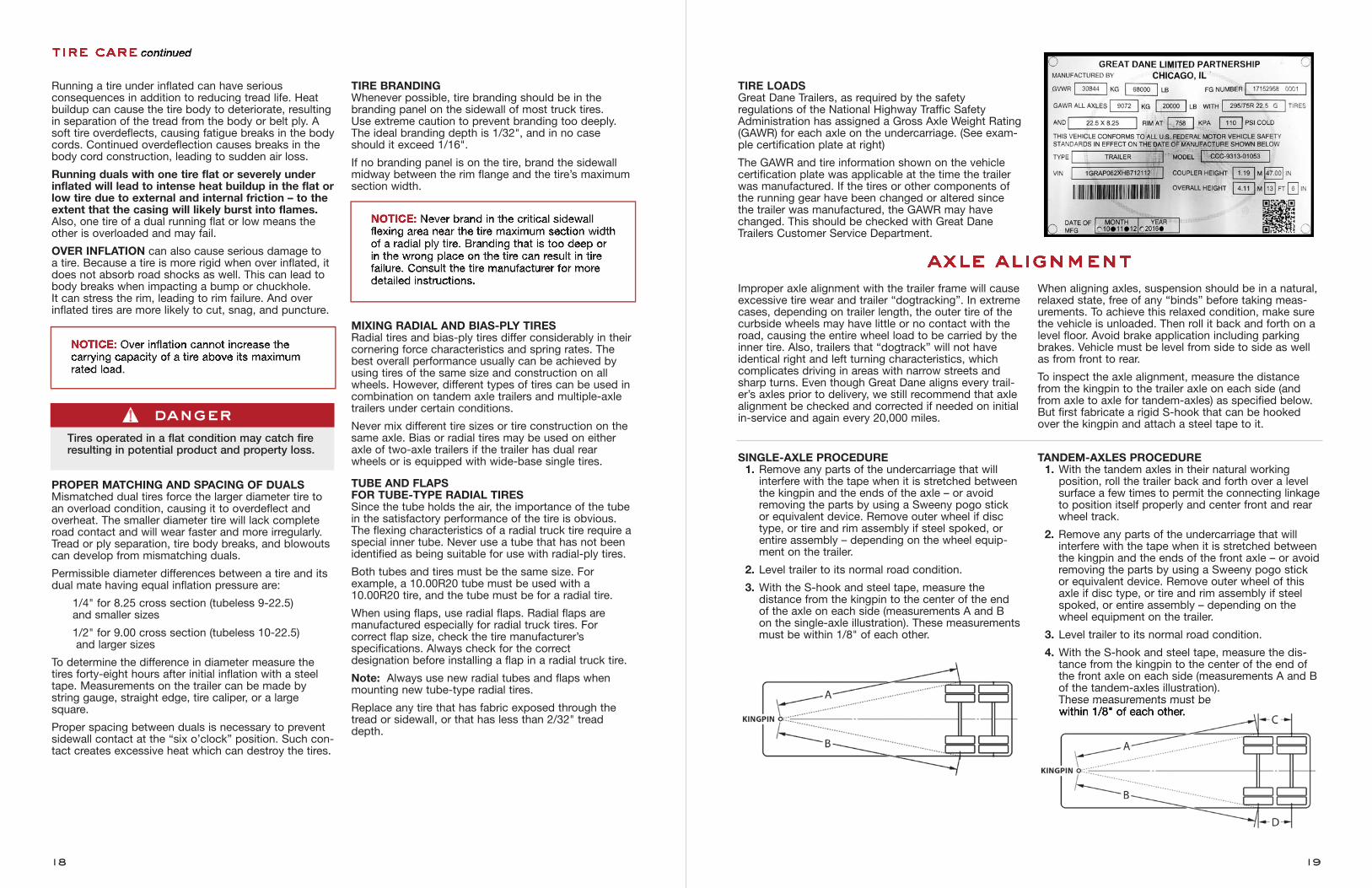
TIRE LOADSGreat Dane Trailers, as required by the safety regulations of the National Highway Traffic SafetyAdministration has assigned a Gross Axle Weight Rating(GAWR) for each axle on the undercarriage. (See exam-ple certification plate at right)
The GAWR and tire information shown on the vehiclecertification plate was applicable at the time the trailerwas manufactured. If the tires or other components ofthe running gear have been changed or altered sincethe trailer was manufactured, the GAWR may havechanged. This should be checked with Great DaneTrailers Customer Service Department.
Improper axle alignment with the trailer frame will causeexcessive tire wear and trailer “dogtracking”. In extremecases, depending on trailer length, the outer tire of thecurbside wheels may have little or no contact with theroad, causing the entire wheel load to be carried by theinner tire. Also, trailers that “dogtrack” will not haveidentical right and left turning characteristics, whichcomplicates driving in areas with narrow streets andsharp turns. Even though Great Dane aligns every trail-er’s axles prior to delivery, we still recommend that axlealignment be checked and corrected if needed on initialin-service and again every 20,000 miles.
When aligning axles, suspension should be in a natural,relaxed state, free of any “binds” before taking meas-urements. To achieve this relaxed condition, make surethe vehicle is unloaded. Then roll it back and forth on alevel floor. Avoid brake application including parkingbrakes. Vehicle must be level from side to side as wellas from front to rear.
To inspect the axle alignment, measure the distancefrom the kingpin to the trailer axle on each side (andfrom axle to axle for tandem-axles) as specified below.But first fabricate a rigid S-hook that can be hookedover the kingpin and attach a steel tape to it.
SINGLE-AXLE PROCEDURE1. Remove any parts of the undercarriage that willinterfere with the tape when it is stretched betweenthe kingpin and the ends of the axle – or avoidremoving the parts by using a Sweeny pogo stickor equivalent device. Remove outer wheel if disctype, or tire and rim assembly if steel spoked, orentire assembly – depending on the wheel equip-ment on the trailer.
2. Level trailer to its normal road condition.
3. With the S-hook and steel tape, measure the distance from the kingpin to the center of the end of the axle on each side (measurements A and B on the single-axle illustration). These measurementsmust be within 1/8" of each other.
TANDEM-AXLES PROCEDURE1. With the tandem axles in their natural working position, roll the trailer back and forth over a levelsurface a few times to permit the connecting linkageto position itself properly and center front and rearwheel track.
2. Remove any parts of the undercarriage that willinterfere with the tape when it is stretched betweenthe kingpin and the ends of the front axle – or avoidremoving the parts by using a Sweeny pogo stickor equivalent device. Remove outer wheel of thisaxle if disc type, or tire and rim assembly if steelspoked, or entire assembly – depending on thewheel equipment on the trailer.
3. Level trailer to its normal road condition.
4. With the S-hook and steel tape, measure the dis-tance from the kingpin to the center of the end of the front axle on each side (measurements A and Bof the tandem-axles illustration). These measurements must be within 1/8" of each other.
tire care continued
NOTICE: Over inflation cannot increase thecarrying capacity of a tire above its maximumrated load.
NOTICE: Never brand in the critical sidewallflexing area near the tire maximum section widthof a radial ply tire. Branding that is too deep orin the wrong place on the tire can result in tirefailure. Consult the tire manufacturer for moredetailed instructions.
dangerTires operated in a flat condition may catch fireresulting in potential product and property loss.
axle alignment
20 21
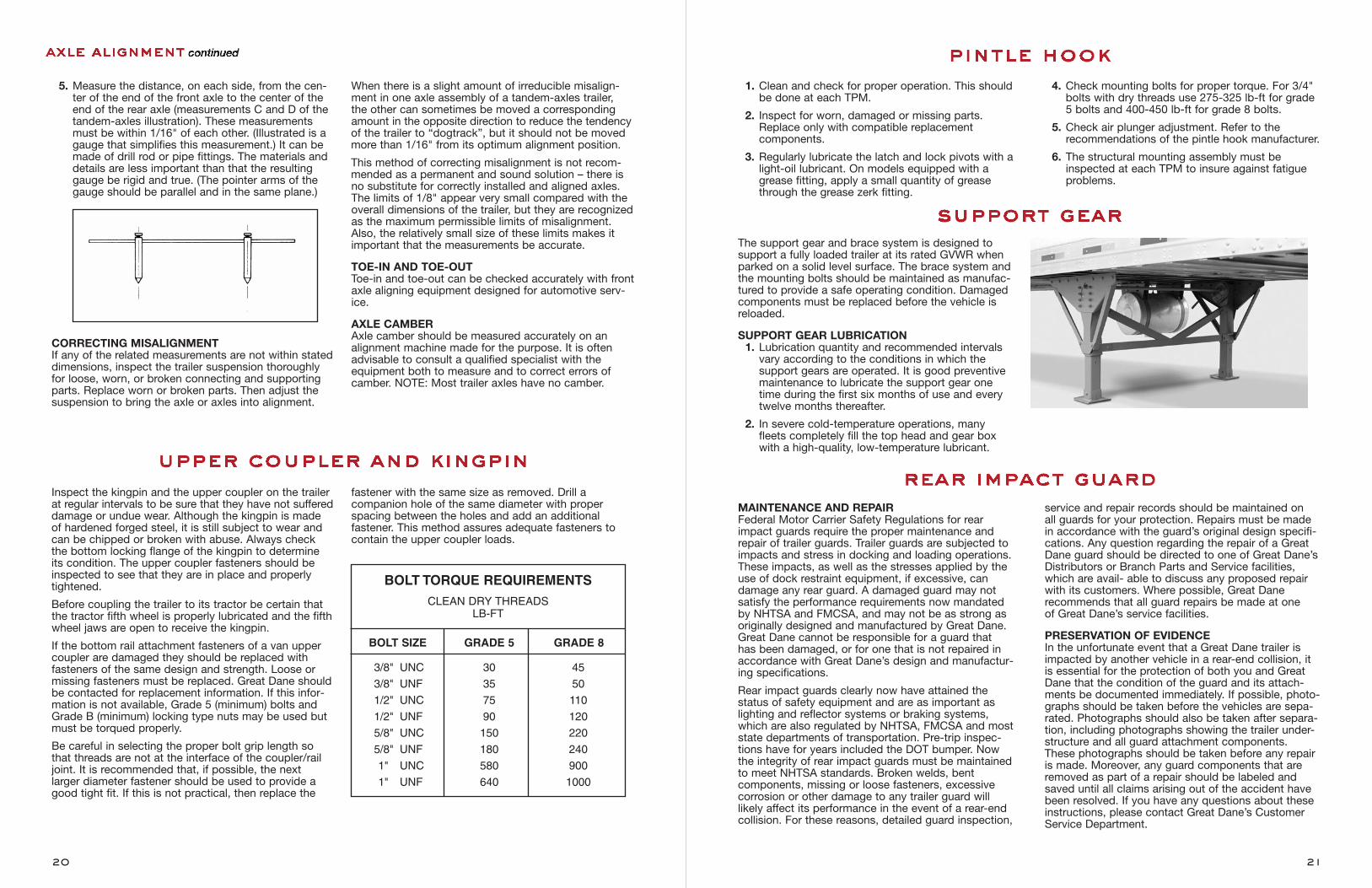
5. Measure the distance, on each side, from the cen-ter of the end of the front axle to the center of theend of the rear axle (measurements C and D of the tandem-axles illustration). These measurementsmust be within 1/16" of each other. (Illustrated is agauge that simplifies this measurement.) It can bemade of drill rod or pipe fittings. The materials anddetails are less important than that the resultinggauge be rigid and true. (The pointer arms of thegauge should be parallel and in the same plane.)
CORRECTING MISALIGNMENTIf any of the related measurements are not within stateddimensions, inspect the trailer suspension thoroughlyfor loose, worn, or broken connecting and supportingparts. Replace worn or broken parts. Then adjust thesuspension to bring the axle or axles into alignment.
When there is a slight amount of irreducible misalign-ment in one axle assembly of a tandem-axles trailer, the other can sometimes be moved a correspondingamount in the opposite direction to reduce the tendencyof the trailer to “dogtrack”, but it should not be movedmore than 1/16" from its optimum alignment position.
This method of correcting misalignment is not recom-mended as a permanent and sound solution – there isno substitute for correctly installed and aligned axles.The limits of 1/8" appear very small compared with theoverall dimensions of the trailer, but they are recognizedas the maximum permissible limits of misalignment.Also, the relatively small size of these limits makes itimportant that the measurements be accurate.
TOE-IN AND TOE-OUTToe-in and toe-out can be checked accurately with frontaxle aligning equipment designed for automotive serv-ice.
AXLE CAMBERAxle camber should be measured accurately on analignment machine made for the purpose. It is oftenadvisable to consult a qualified specialist with theequipment both to measure and to correct errors ofcamber. NOTE: Most trailer axles have no camber.
Inspect the kingpin and the upper coupler on the trailerat regular intervals to be sure that they have not suffereddamage or undue wear. Although the kingpin is made of hardened forged steel, it is still subject to wear andcan be chipped or broken with abuse. Always check the bottom locking flange of the kingpin to determine its condition. The upper coupler fasteners should beinspected to see that they are in place and properlytightened.
Before coupling the trailer to its tractor be certain thatthe tractor fifth wheel is properly lubricated and the fifthwheel jaws are open to receive the kingpin.
If the bottom rail attachment fasteners of a van uppercoupler are damaged they should be replaced with fasteners of the same design and strength. Loose ormissing fasteners must be replaced. Great Dane shouldbe contacted for replacement information. If this infor-mation is not available, Grade 5 (minimum) bolts andGrade B (minimum) locking type nuts may be used butmust be torqued properly.
Be careful in selecting the proper bolt grip length sothat threads are not at the interface of the coupler/railjoint. It is recommended that, if possible, the next larger diameter fastener should be used to provide agood tight fit. If this is not practical, then replace the
fastener with the same size as removed. Drill a companion hole of the same diameter with properspacing between the holes and add an additional fastener. This method assures adequate fasteners tocontain the upper coupler loads.
axle alignment continued
upper coupler and kingpin
1. Clean and check for proper operation. This shouldbe done at each TPM.
2. Inspect for worn, damaged or missing parts.Replace only with compatible replacement components.
3. Regularly lubricate the latch and lock pivots with alight-oil lubricant. On models equipped with agrease fitting, apply a small quantity of greasethrough the grease zerk fitting.
4. Check mounting bolts for proper torque. For 3/4"bolts with dry threads use 275-325 lb-ft for grade 5 bolts and 400-450 lb-ft for grade 8 bolts.
5. Check air plunger adjustment. Refer to the recommendations of the pintle hook manufacturer.
6. The structural mounting assembly must beinspected at each TPM to insure against fatigueproblems.
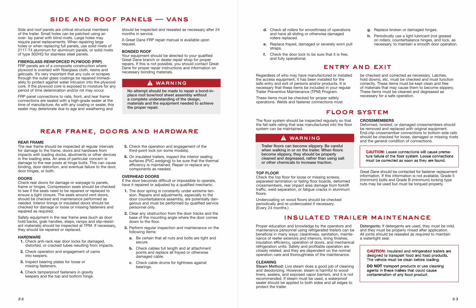
The support gear and brace system is designed tosupport a fully loaded trailer at its rated GVWR whenparked on a solid level surface. The brace system andthe mounting bolts should be maintained as manufac-tured to provide a safe operating condition. Damagedcomponents must be replaced before the vehicle isreloaded.
SUPPORT GEAR LUBRICATION1. Lubrication quantity and recommended intervalsvary according to the conditions in which the support gears are operated. It is good preventivemaintenance to lubricate the support gear onetime during the first six months of use and everytwelve months thereafter.
2. In severe cold-temperature operations, manyfleets completely fill the top head and gear boxwith a high-quality, low-temperature lubricant.
pintle hook
support gear
MAINTENANCE AND REPAIRFederal Motor Carrier Safety Regulations for rearimpact guards require the proper maintenance andrepair of trailer guards. Trailer guards are subjected toimpacts and stress in docking and loading operations.These impacts, as well as the stresses applied by theuse of dock restraint equipment, if excessive, candamage any rear guard. A damaged guard may notsatisfy the performance requirements now mandatedby NHTSA and FMCSA, and may not be as strong asoriginally designed and manufactured by Great Dane.Great Dane cannot be responsible for a guard that has been damaged, or for one that is not repaired inaccordance with Great Dane’s design and manufactur-ing specifications.
Rear impact guards clearly now have attained the status of safety equipment and are as important aslighting and reflector systems or braking systems,which are also regulated by NHTSA, FMCSA and moststate departments of transportation. Pre-trip inspec-tions have for years included the DOT bumper. Nowthe integrity of rear impact guards must be maintainedto meet NHTSA standards. Broken welds, bent components, missing or loose fasteners, excessivecorrosion or other damage to any trailer guard willlikely affect its performance in the event of a rear-endcollision. For these reasons, detailed guard inspection,
service and repair records should be maintained on all guards for your protection. Repairs must be madein accordance with the guard’s original design specifi-cations. Any question regarding the repair of a GreatDane guard should be directed to one of Great Dane’sDistributors or Branch Parts and Service facilities,which are avail- able to discuss any proposed repairwith its customers. Where possible, Great Dane recommends that all guard repairs be made at one of Great Dane’s service facilities.
PRESERVATION OF EVIDENCEIn the unfortunate event that a Great Dane trailer isimpacted by another vehicle in a rear-end collision, itis essential for the protection of both you and GreatDane that the condition of the guard and its attach-ments be documented immediately. If possible, photo-graphs should be taken before the vehicles are sepa-rated. Photographs should also be taken after separa-tion, including photographs showing the trailer under-structure and all guard attachment components.These photographs should be taken before any repairis made. Moreover, any guard components that areremoved as part of a repair should be labeled andsaved until all claims arising out of the accident havebeen resolved. If you have any questions about theseinstructions, please contact Great Dane’s CustomerService Department.
rear impact guard
BOLT TORQUE REQUIREMENTS
CLEAN DRY THREADSLB-FT
BOLT SIZE GRADE 5 GRADE 8
3/8" UNC 30 45
3/8" UNF 35 50
1/2" UNC 75 110
1/2" UNF 90 120
5/8" UNC 150 220
5/8" UNF 180 240
1" UNC 580 900
1" UNF 640 1000
Side and roof panels are critical structural members of the trailer. Small holes can be patched using an over- lay panel with blind rivets. Large holes mayrequire panel replacements. When repairing large holes or when replacing full panels, use solid rivets of2117-T4 aluminum for aluminum panels, or solid rivetsof type 302HQ for stainless steel panels.
FIBERGLASS-REINFORCED PLYWOOD (FRP) FRP panels are of a composite construction where plywood is overlaid with fiberglass cloth, resins and gelcoats. It’s very important that any cuts or scrapesthrough the outer glass coatings be repaired immedi-ately to protect against water intrusion into the plywoodcore. If the plywood core is exposed to moisture for anyperiod of time delamination and/or rot may occur.
FRP panel connections to rails, front, and rear frameconnections are sealed with a high-grade sealer at thetime of manufacture. As with any coating or sealer, thissealer may deteriorate due to age and weathering and
should be inspected and resealed as necessary after 24months in service.
A Great Dane FRP repair manual is available uponrequest.
BONDED ROOFYour equipment should be directed to your qualifiedGreat Dane branch or dealer repair shop for properrepairs. If this is not possible, you should contact GreatDane for proper repair instructions and information onnecessary bonding materials.
d. Check all rollers for smoothness of operationsand have all sliding or otherwise damagedrollers replaced.
e. Replace frayed, damaged or severely worn pullstraps.
f. Check the door lock to be sure that it is free,and fully operational.
g. Replace broken or damaged hinges.
h. Periodically use a light lubricant (not grease) on rollers, counterbalance hinges, and lock, asnecessary, to maintain a smooth door operation.
Regardless of who may have manufactured or installedthe access equipment, it has been installed for the safe entry and exit of persons and/or products. It isnecessary that these items be included in your regularTrailer Preventive Maintenance (TPM) Program.
These items must be checked for proper safety operations. Welds and fastener connections must
be checked and corrected as necessary. Latches, hold downs, etc. must be checked and must function correctly. These items must be kept clean and free of materials that may cause them to become slippery.These items must be cleaned and degreased as necessary for a safe operation.
2322
side and roof panels — vans
REAR FRAMEThe rear frame should be inspected at regular intervalsfor damage to the frame, doors and hardware fromimpacts with loading docks, abutments or other devicesin the loading area. An area of particular concern isdamage to the rear posts at hinge butts. This can causebinding, door distortion, and eventual failure to the door,door hinges, or both.
DOORSCheck rear doors for damage or warpage to panels,frame or hinges. Compression seals should be checkedto see if the seals need to be repaired or replaced toensure a tight closure. The seals around vent doors,should be checked and maintenance performed asneeded. Interior linings or insulated doors should bechecked for damage or loose or missing fasteners andrepaired as required.
Safety equipment in the rear frame area (such as doorhold backs, grab handles, steps, ramps and slip-resist-ant materials) should be inspected at TPM. If necessary,they should be repaired or replaced.
HARDWARE1. Check anti-rack rear door locks for damaged, distorted, or cracked tubes resulting from impacts.
2. Check operation and engagement of cams into keepers.
3. Inspect bearing plates for loose or missing fasteners.
4. Check tamperproof fasteners in gravity keepers and the top and bottom hinge.
5. Check the operation and engagement of the third-point lock (on some models).
6. On insulated trailers, inspect the interior sealing surfaces (PVC wedging) to be sure that the thermalefficiency is maintained. Repair or replace any components as needed.
OVERHEAD DOORSIf the door becomes difficult or impossible to operate,have it repaired or adjusted by a qualified mechanic.
1. The door spring is constantly under extreme ten-sion. Repairs and adjustments, especially to thedoor counterbalance assembly, are potentially dan-gerous and must be performed by qualified servicepersonnel only.
2. Clear any obstruction from the door tracks and thebase of the mounting angle where the door comesdown to the floor.
3. Perform regular inspection and maintenance on thefollowing items:
a. Be certain that all nuts and bolts are tight andsecure.
b. Check cables full length and at attachmentpoints and replace all frayed or otherwise damaged cable.
c. Check cable drums for tightness against bearings.
rear frame, doors and hardware
entry and exit
The floor system should be inspected regularly so thatthe fail-safe rating that was manufactured into the floorsystem can be maintained.
TOP FLOORCheck the top floor for loose or missing screws, separated lamination or failing floor boards, deformedcrossmembers, rear impact area damage from forklifttraffic, weld separation, or fatigue cracks in aluminumfloors.
Undercoating on wood floors should be checked periodically and re-undercoated if necessary. (Every 24 months.)
CROSSMEMBERSDeformed, twisted, or damaged crossmembers shouldbe removed and replaced with original equipment. End-clip crossmember connections to bottom side railsshould be checked for loose, damaged or missing rivetsand the general condition of connections.
Great Dane should be contacted for fastener replacementinformation. If this information is not available, Grade 5(minimum) bolts and Grade B (minimum) locking typenuts may be used but must be torqued properly.
Proper education and knowledge by the operators andmaintenance personnel using refrigerated trailers can bebeneficial in many ways: cleanliness, sanitation, mainte-nance of reefer exteriors and interiors, lining finishes,insulation efficiency, operation of doors, and mechanicalrefrigeration units. Safety and profitable operation areclosely related, and they are dependent on the normaloperation care and thoroughness of the maintenance.
CLEANINGSteam Method: Live steam does a good job of cleaningand deodorizing. However, steam is harmful to woodliners, sealers, and exposed vapor barriers, and it is notrecommended. If steam must be used, a waterproofsealer should be applied to both sides and all edges toprotect the trailer.
Detergents: If detergents are used, they must be mild,and they must be properly rinsed after application. All joints should be resealed as required to maintain a watertight seal.
floor system
insulated trailer maintenance
warningNo attempt should be made to repair a bond-in-place roof bow/roof sheet assembly without a complete understanding of the design, materials and the equipment needed to achievethe proper repair.
warningTrailer floors can become slippery. Be carefulwhen walking in or on the trailer. When floorsbecome slippery, they should be properlycleaned and degreased, rather than using saltor other chemicals to increase traction.
CAUTION: Loose connections will cause prema-ture failure of the floor system. Loose connectionsmust be corrected as soon as they are found.
CAUTION: Insulated and refrigerated trailers aredesigned to transport food and food products.The vehicle must be clean before loading.
DO NOT transport products or use cleaningagents in these trailers that could cause contamination of any food product.
Exteriors: Cleaning the outside of refrigerated trailersshould be done the same way dry-freight vans arecleaned. Live steam does a good job of cleaning andbrightening the exterior surfaces of van trailers.Application of a protective transparent coating may beused to protect the exterior surface from further oxida-tion. Do not use brighteners or acids on the trailer.
Note: A trailer with open holes should not be steamcleaned until the holes have been patched or panelsreplaced. Allowing moisture or chemicals to enter thewalls or roof through holes will cause corrosion andmay add weight to the trailer.
CHECK INSULATION EFFICIENCYWeigh the trailer at regular intervals to determine if there is moisture accumulation or water pickup through condensation or leakage into the insulation.
Check for spots where water may leak out during clean-ing, other than from regular drain holes. This indicateswater entrance into the insulation. The areas allowingwater to enter must be located and properly sealed.
Keep a record of the length of time the mechanicalrefrigeration unit cycles and its frequency. An increase,of an appreciable degree, in frequency and in durationof the cycles, or both, could indicate a general deterio-ration either in the trailer insulation or refrigeration unit.
Excessive air leakage may cause the refrigeration unitto run for long periods of time. Excessive air leakageindicates problems such as perforated walls or wornout areas of door seals or door locks around vents, sidedoors, and refrigeration units. These areas should berepaired.
MOISTURE PICKUP THROUGH CONDENSATIONIf it has been determined that you have moisture contamination in the insulation cavity, you should take one of the following steps:
a. Open the doors of the trailer and park it in the sun. It takes several days of hot, sunny weather toequalize water vapors trapped in the trailer bodywith that of the outside air, or;
b. Place the trailer in a controlled-heat, paint-dryingoven to speed up the process of drying.
RAIN WATER LEAKAGEa. Check outside and inside of trailer for holes andloose joint seams through which moisture mayseep.
b. Waterproof all openings immediately by patchingand sealing, or both, especially after accidents inwhich body and roof skin may have been cut.Synthetic-rubber-base-type sealer should be usedfor closing all minor openings.
EXCESSIVE CYCLING OF REFRIGERATION UNITIf the unit is operating properly, the excessive cyclingcould be caused by:
a. Air transfer through leaking door seals.
b. Deterioration of insulation.
c. Unusually hot surrounding temperature.
d. Refrigeration unit improperly sized for the intendedtemperature for that cargo.
SUBFLOORSSince subfloors are enclosed on the top side and openat the bottom, they are subject to considerable roadsplash and corrosion. Where they have deterioratedthey should be repaired or replaced.
DOORS, VENTS, HATCHESWhen seals are worn out they must be replaced. Check and correct, as required, the alignment of doorhinges and locks.
URETHANE FOAM FLAMMABILITYUrethane foam has achieved an extensive history in avariety of applications, including insulation in refrigerat-ed trailers, because the performance of urethane insula-tion has been superior to other materials.
One area of concern is the fire potential and flammabilityof urethane when exposed during repair of surroundingareas. Urethane foam is combustible like cork, wood orother organic materials. When urethane is exposed tothe intense heat of welding, flame cutting or other hotwork wherein a high-density heat source is used inrepairing an insulated trailer, certain precautions mustbe observed. Urethane foam burns (including fire-retar-dant types) producing toxic smoke which may or maynot be visible to personnel.
PRECAUTIONARY MEASURESClean the work area. Never allow urethane scrap or other organic materials to be in the work area oraround the trailer. Do not allow foam material to accumulate on the job site.
1. Under no circumstances shall a direct flame beallowed to contact urethane foam. Urethane foammust be mechanically cut away and totally removedfrom around the repair area by at least two feet oran obviously safe distance away to prevent anyflame from coming in contact with the urethanematerials.
2. All combustible materials below the workpiece must be removed to prevent ignition from hotsparks or slag.
24 25
3. Should ignition or combustion of the urethanebecome evident (flame, smoke, charring, odor, etc.),hot work must be stopped immediately. All flamesmust be extinguished and additional urethanematerials must be removed from the workpieceand/or workplace before hot work is continued.
4. A fire watcher equipped with a 15-pound CO2 ordry-chemical extinguisher must be posted at thejob site during all hot work operations, and mustremain for at least 30 minutes after such operationshave been completed.
5. All work involving heat, especially burning and welding, must be performed in a well-ventilatedarea.
6. Interrupt burning and welding occasionally to prevent a buildup of heat.
7. Workers shall know what to do in the event of anemergency. Prior to work being started, workersmust be aware of how to contact fire and medicalpersonnel should the need arise.
8. In the event a urethane fire is encountered, immediate steps shall be taken to avoid breathingthe toxic fumes associated with such fires.
Personnel fighting the fire must be equipped withNIOSH-approved, self-contained breathing appara-tus. Personnel not equipped with NIOSH-approved,self-contained breathing apparatus must leave thearea immediately.
MAIN BEAMSPlatform trailers are constructed such that the mainbeams provide both the load-bearing and load-carryingcapability. It is important that no welding, burning,drilling, etc. ever be done on these main beams, as the structural capability will likely be drastically affected.No such items as sliding-base winches should beadded to these beams as they would tend to twist thebeams, especially on wide-frame platforms. The abilityof these beams to take loads would be impaired due to the twisting.
If modification of the beam is ever necessary, the factory should be consulted prior to doing the work.
CROSSMEMBERSCrossmembers are used not only to carry loads into themain beams but are also used to maintain the mainbeams in a vertical direction. Any area where cross
members have been removed for any reason maycause twisting of the main beams and could cause astructural failure.
EXTENDABLE PLATFORMSThe extendable platforms have more inspection pointsdue to their complexity. In addition to the main rails andcrossmembers, the lock pins should be inspected forproper protrusion and wear. If the diameter of the lockpin has 1/4" or more of wear it should be replaced.
The lock-pin safety-lock mechanism should also beinspected for proper operation. The two sections rideon rollers that have fittings to allow them to be greasedat regular intervals. One additional caution is to keepthe caps on all air connectors when they are not in use. These caps are necessary to keep dirt out of the air system.
The fifth wheel on the dolly should be maintained inaccordance with the vendor’s recommendations. Thesuspension should be maintained following the samerecommended preventative maintenance practices aspreviously listed for trailers.
Maintenance of grease lubricants on the fifth-wheelrace is critical in the operation of multi-unit equipment.Dry fifth-wheel tables will result in “sticking” of the coupler plates during operation which can result in a “whipping” action of the multi-unit equipment.
maintaining insulation efficiency
platform trailers
converter dolly
safety measures — urethane foam
insulation trailer maintenance continued
warningThis trailer is insulated with urethane foam whichis an organic material.
The following precautions shall be observed:
1. Urethane foam will burn when exposed toflame or extreme heat. Foam shall be shield-ed with a thermal barrier when welding ortorch cutting in its vicinity. Fire extinguishingequipment should be readily available.
2. Fires involving urethane can be extinguishedwith water, carbon dioxide or dry chemicals.Personnel fighting the fire shall be equippedwith NIOSH-approved, self-contained breath-ing apparatus.
warningAll coupling and safety devices associated withmulti-unit operation must be inspected prior toeach coupling to insure safe operation.
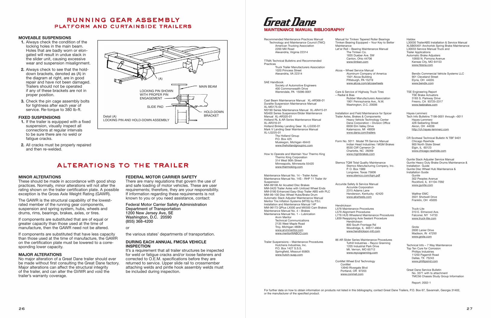
Recommended Maintenance Practices ManualTechnology and Maintenance Council (TMC)
American Trucking Association2200 Mill RoadAlexandria, Virginia 22314
TTMA Technical Bulletins and RecommendedPractices
Truck Trailer Manufacturers Association1020 Princess StreetAlexandria, VA 22314
SAE HandbookSociety of Automotive Engineers400 Commonwealth DriveWarrendale, PA 15096-0001
Cast Beam Maintenance Manual XL-AR368-01Duralite Suspension Maintenance Manual XL-MS175-02NS190 Series Maintenance Manual XL-AR415-01NS400 Series Suspension/Slider MaintenanceManual XL-AR320-01Holland RL & AR Series Maintenance Manual XL-AR316-01Holland Binkley Landing Gear XL-LG330-01Mark V Landing Gear Maintenance Manual XL-LG225-01
The Holland GroupP.O. Box 425Muskegon, Michigan 49443www.thehollandgroupinc.com
How to Operate and Maintain Your Thermo KingThermo King Corporation314 West 90th StreetMinneapolis, Minnesota 55420www.thermoking.com
Maintenance Manual No. 14 - Trailer AxlesMaintenance Manual No. 14S - RHP 11 Trailer AirSuspensionMM-99108 Air Acuated Disc BrakesMM-0420 Trailer Axles with Unitized Wheel EndsMM-0180 Enhanced Easy-Stop Trailer ABS with PLCMM-99-100 Disc Wheel Hubs/Brake DrumAutomatic Slack Adjuster Maintenance ManualMeritor Tire Inflation Systems (MTIS) by P.S.I.Installation and Maintenance Manual 14PMM-96173 QPlus LX500 and MX500 Cam BrakesMaintenance Manual No. 4 – BrakesMaintenance Manual No. 1 – Lubrication
Arvin MeritorTechnical Communications2135 West Maple RoadTroy, Michigan 48084www.arvinmeritor.comwww.meritorWABCO.com
Trailer Suspensions – Maintenance ProceduresHutchens Industries, Inc.P.O. Box 1427 S.S.S.Springfield, Missouri 65805www.hutch-susp.com
Manual for Timken Tapered Roller BearingsTimken Bearing Equipped – Your Key to BetterMaintenanceLet’er Roll – Bearing Maintenance Manual
The Timken Co.1835 Dueber Ave. SWCanton, Ohio 44706www.timken.com
Alcoa – Wheel Service ManualAluminum Company of America1501 Alcoa BuildingPittsburgh, PA 15219www.alcoa.com/alcoawheels
Care & Service of Highway Truck Tires – Radial & Bias
Rubber Manufacturers Association1901 Pennsylvania Ave., N.W.Washington, D.C. 20006
Installation and Field Maintenance for SpicerTrailer Axles, Brakes & Components
Heavy Vehicle Technology CenterDana Corporation – Division Office6938 Elm Valley DriveKalamazoo, MI 49009www.dana.com/trailers
Form No. 5011 Model TR Service ManualIndian Head Industries / MGM Brakes8530 Cliff Cameron DrCharlotte, NC 28269www.mgmbrakes.com
Stemco TQM Total Quality MaintenanceStemco Manufacturing Company, Inc.P. O. Box 1989Longview, Texas 75606www.stemco.com/tqm.pdf
Accuride Safety & Service ManualAccuride Corporation2315 Adams LaneHenderson, Kentucky 42420www.akwheels.com
HendricksonL578 Maintenance ProceduresL579 Alignment ProceduresL776 HUS Wheelend Maintenance ProceduresL839 Reapplying Axle Sealant Procedure
Hendrickson800 South Frontage RdWoodridge, IL 60517-4904www.hendrickson-intl.com
86 AR Slider Series Maintenance ProceduresTuthill Industries – Reyco Granning1205 Industrial Park DriveMt. Vernon, MO 65712www.reycogranning.com
ConMet Wheel End TechnologyConMet13940 Rivergate BlvdPortland, OR 97203www.conmet.com
HaldexL30030 TrailerABS Installation & Service ManualXLSB05401 Anchorlok Spring Brake Maintenance L30033 Service Manual Truck and Trailer ApplicationsAutomatic Brake Adjusters
10930 N. Pomona AvenueKansas City, MO 64153www.hbsna.com
Bendix Commercial Vehicle Systems LLC901 Cleveland StreetElyria, OH 44035www.bendix.com
TSE Engineering ReportTSE Brake Actuators3183 S. Parkway DriveFresno, CA 93725-2317www.tsebrakes.com
Hayes-LemmerzTech Info Bulletins T198-0001 through –0011
Hayes-Lemmerz428 Seiberling StreetAkron, OH 44036http://ch.hayes-lemmerz.com
CR Scotseal Technical Bulletin N TBF 9401Chicago Rawhide900 North State StreetElgin, IL 60123www.chicago-rawhide.com
Gunite Slack Adjuster Service ManualGunite Heavy Duty Brake Drums Maintenance &Installation GuideGunite Disc Wheel Hub Maintenance & Installation Guide
Gunite302 Peoples AvenueRockford, IL 61104-7092www.gunite.com
Walther EMC3501 Shotwell DriveFranklin, OH 45005
Truck-Lite310 E. Elmwood Ave.Falconer, NY 14733www.truck-lite.com
Grote 2600 Lanier DriveMadison, IN 47250www.grote.com
Technical Info – 7 Way MaintenanceTop Ten Cure for Corrosion
Phillips Industries11250 Pagemill RoadDallas, TX 75243www.phillipsind.com
Great Dane Service Bulletin No. 3371 with ts attachment TMC56 Chassis Study Group Information
Report: 2002-1
MAINTENANCE MANUAL BIBLIOGRAPHY
For further data on how to obtain information on products not listed in this bibliography, contact Great Dane Trailers, P.O. Box 67, Savannah, Georgia 31402, or the manufacturer of the specified product.
MOVEABLE SUSPENSIONS1. Always check the condition of thelocking holes in the main beam.Holes that are badly worn or elon-gated will result in undue slack inthe slider unit, causing excessivewear and suspension misalignment.
2. Always check to see that the hold-down brackets, denoted as (A) in the diagram at right, are in goodrepair and have not been damaged.Trailers should not be operated if any of these brackets are not inproper position.
3. Check the pin cage assembly boltsfor tightness after each year of service. Re-torque to 380 lb-ft.
FIXED SUSPENSIONS1. If the trailer is equipped with a fixed suspension, visually inspect all connections at regular intervals to be sure there are no weld or fatigue cracks.
2. All cracks must be properly repaired and then re-welded.
MINOR ALTERATIONSThese should be made in accordance with good shoppractices. Normally, minor alterations will not alter therating shown on the trailer certification plate. A possibleexception is the Gross Axle Weight Rating (GAWR).
The GAWR is the structural capability of the lowest-rated member of the running gear components, suspension and spring system, hubs, wheels anddrums, rims, bearings, brakes, axles, or tires.
If components are substituted that are of equal orgreater capacity than those used at the time of manufacture, then the GAWR need not be altered.
If components are substituted that have less capacitythan those used at the time of manufacture, the GAWRon the certification plate must be lowered to a corre-sponding lower capacity.
MAJOR ALTERATIONSNo major alteration of a Great Dane trailer should everbe made without first consulting the Great Dane factory.Major alterations can affect the structural integrity of the trailer, and can alter the GVWR and void the trailer’s warranty coverage.
FEDERAL MOTOR CARRIER SAFETYThere are many regulations that govern the use of and safe loading of motor vehicles. These are user requirements; therefore, they are your responsibility. If information regarding these requirements is notknown to you or you need assistance, contact:
Federal Motor Carrier Safety AdministrationDepartment of Transportation1200 New Jersey Ave, SEWashington, D.C. 20590(855) 368-4200
or
the various states’ departments of transportation.
DURING EACH ANNUAL FMCSA VEHICLEINSPECTIONIt’s a requirement that all trailer structures be inspectedfor weld or fatigue cracks and/or loose fasteners andcorrected to O.E.M. specifications before they arereturned to service. Upper slide rail to crossmemberattaching welds and pintle hook assembly welds mustbe included during inspection.
26
LOCKING PIN SHOWNWITH PROPER PIN ENGAGEMENT
SLIDE PAD
HOLD-DOWNBRACKET
MAIN BEAM
(A)
Detail (A)LOCKING PIN AND HOLD-DOWN ASSEMBLY
27
running gear assemblyplatform and curtainside trailers
alterations to the trailer
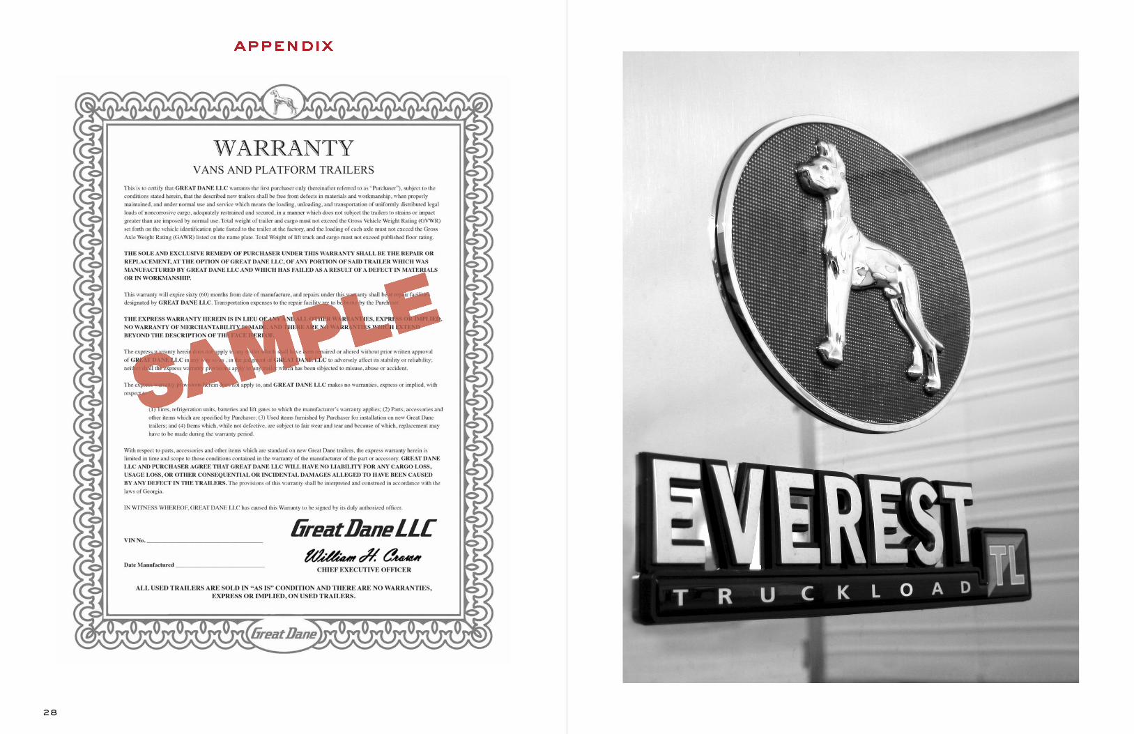
28
appendix
638 DM
D 0218
$2.00 USD
www.greatdane.comGreat Dane and the oval are registered trademarks of Great Dane LLC.
dr ive away w i th more

Top Related